Embed Size (px)
Citation preview

SAN management with the CLIONTAP 9NetAppMarch 10, 2022
This PDF was generated from https://docs.netapp.com/us-en/ontap/san-admin/index.html on March 10,2022. Always check docs.netapp.com for the latest.
Table of Contents
SAN management with the CLI . . . . . . . . . . . . . . . . . . . . . . . . . . . . . . . . . . . . . . . . . . . . . . . . . . . . . . . . . . . . . . 1
SAN administration overview with the CLI . . . . . . . . . . . . . . . . . . . . . . . . . . . . . . . . . . . . . . . . . . . . . . . . . . . . 1
Set up LUNs for FC and iSCSI. . . . . . . . . . . . . . . . . . . . . . . . . . . . . . . . . . . . . . . . . . . . . . . . . . . . . . . . . . . . . 1
Set up namespaces for NVMe . . . . . . . . . . . . . . . . . . . . . . . . . . . . . . . . . . . . . . . . . . . . . . . . . . . . . . . . . . . . . 7
Manage LUNs for FC and iSCSi . . . . . . . . . . . . . . . . . . . . . . . . . . . . . . . . . . . . . . . . . . . . . . . . . . . . . . . . . . 11
Recommended volume and file or LUN configuration combinations . . . . . . . . . . . . . . . . . . . . . . . . . . . . . . . 21
Selective LUN Map . . . . . . . . . . . . . . . . . . . . . . . . . . . . . . . . . . . . . . . . . . . . . . . . . . . . . . . . . . . . . . . . . . . . 26
Manage iSCSI protocol . . . . . . . . . . . . . . . . . . . . . . . . . . . . . . . . . . . . . . . . . . . . . . . . . . . . . . . . . . . . . . . . . 28
Manage FC protocol. . . . . . . . . . . . . . . . . . . . . . . . . . . . . . . . . . . . . . . . . . . . . . . . . . . . . . . . . . . . . . . . . . . . 34
Manage systems with FC adapters . . . . . . . . . . . . . . . . . . . . . . . . . . . . . . . . . . . . . . . . . . . . . . . . . . . . . . . . 34
Manage NVMe protocol . . . . . . . . . . . . . . . . . . . . . . . . . . . . . . . . . . . . . . . . . . . . . . . . . . . . . . . . . . . . . . . . . 41
Manage LIFs for all SAN protocols . . . . . . . . . . . . . . . . . . . . . . . . . . . . . . . . . . . . . . . . . . . . . . . . . . . . . . . . 43
Data protection methods in SAN environments . . . . . . . . . . . . . . . . . . . . . . . . . . . . . . . . . . . . . . . . . . . . . . . 48
Considerations for SAN configurations in a MetroCluster environment. . . . . . . . . . . . . . . . . . . . . . . . . . . . . 67
SAN Concepts . . . . . . . . . . . . . . . . . . . . . . . . . . . . . . . . . . . . . . . . . . . . . . . . . . . . . . . . . . . . . . . . . . . . . . . . 69

SAN management with the CLI
SAN administration overview with the CLI
Use the following procedures to perform basic SAN host provisioning. You can configure
and manage LUNs, igroups, and targets using the iSCSI and FC protocols, and
namespaces and subsystems using the NVMe/FC protocol.
You should use these procedures under the following circumstances:
• You want to understand the range of ONTAP SAN host provisioning capabilities.
• You want to perform less common configuration and maintenance tasks, not basic SAN configuration.
• You want to use the command-line interface (CLI), not System Manager or an automated scripting tool.
Set up LUNs for FC and iSCSI
LUN guidelines
The FC protocol and iSCSI protocol both provision storage through the use of LUNs. After
you have setup your LUNs, you can perform various management tasks, such as
increasing or decreasing the size of a LUN. After configuring your volume and setting the
appropriate OS type, you must complete the steps that are necessary to setup your LUN.
Guidelines for assigning LUN IDs
Typically, the default LUN ID begins with 0 and is assigned in increments of 1 for each additional mapped LUN.
The host associates the LUN ID with the location and path name of the LUN. The range of valid LUN ID
numbers depends on the host. For detailed information, see the documentation provided with your Host
Utilities.
Guidelines for mapping LUNs to igroups
• You can map a LUN to only one igroup.
• You can map a LUN to only one specific initiator through the igroup.
• You can add a single initiator to multiple igroups, but the initiator can be mapped to only one LUN.
• You cannot use the same LUN ID for two LUNs mapped to the same igroup.
• You should use the same protocol type for igroups and port sets.
LUN setup workflow
To set up your LUN, you must determine the best LUN type for your needs. Then you can
follow a series of tasks to verify your protocol license, enable block access, create and
map your LUN, and enable block access on your host. You can also optionally create and
bind portsets as part of the LUN setup workflow.
1

Other ways to do this in ONTAP
To complete this task using… Refer to…
The redesigned System Manager (available with 9.7
and later)
• Provision SAN storage for VMware datastores
• Provision SAN storage for Linux servers
• Provision SAN storage for Windows servers
System Manager Classic (available with 9.7 and
earlier)
• FC configuration for ESXi using VSC
• FC configuration for Red Hat Enterprise Linux
• FC configuration for Windows
• iSCSI configuration for ESXi using VSC
• iSCSI configuration for Red Hat Enterprise Linux
• iSCSI configuration for Windows
Configure switches for FCoE
You must configure your switches for FCoE before your FC service can run over the
existing Ethernet infrastructure.
What you’ll need
• Your SAN configuration must be supported.
For more information about supported configurations, see the Interoperability Matrix.
• A Unified Target Adapter (UTA) must be installed on your storage system.
If you are using a UTA2, it must be set to cna mode.
• A converged network adapter (CNA) must be installed on your host.
Steps
2

1. Use your switch documentation to configure your switches for FCoE.
2. Use the dcb show command to verify that the DCB settings for each node in the cluster have been
correctly configured.
run -node node1 -command dcb show
DCB settings are configured on the switch. Consult your switch documentation if the settings are incorrect.
3. Use the fcp adapter show command to verify that the FCoE login is working when the FC target port
online status is true.
cluster1::> fcp adapter show -fields node,adapter,status,state,speed,fabric-
established,physical-protocol
If the FC target port online status is false, consult your switch documentation.
Related information
NetApp Interoperability Matrix Tool
NetApp Technical Report 3800: Fibre Channel over Ethernet (FCoE) End-to-End Deployment Guide
Cisco MDS 9000 NX-OS and SAN-OS Software Configuration Guides
Brocade products
Prerequisites for setting up LUNs
Setting up LUNs involves creating a LUN, creating an igroup, and mapping the LUN to
the igroup. Your system must meet certain prerequisites before you can set up your
LUNs.
• The Interoperability Matrix must list your SAN configuration as supported.
• Your SAN environment must meet the SAN host and controller configuration limits specified in NetApp
Hardware Universe for your version of the ONTAP software.
• A supported version of Host Utilities must be installed.
The Host Utilities documentation provides more information.
• You must have SAN LIFs on the LUN owning node and the owning node’s HA partner.
Related information
NetApp Interoperability Matrix Tool
ONTAP SAN Host Configuration
NetApp Technical Report 4017: Fibre Channel SAN Best Practices
Verify the license for FC or iSCSI
Before you can enable block access for a storage virtual machine (SVM) with FC or
iSCSI, you must have a license.
3

Steps
1. Use the system license show command to verify that you have a license for FC or iSCSI.
system license show
Package Type Description Expiration
----------------- ------- --------------------- --------------------
Base site Cluster Base License -
NFS site NFS License -
CIFS site CIFS License -
iSCSI site iSCSI License -
FCP site FCP License -
2. If you do not have a license for FC or iSCSI, use the license add command.
license add -license-code your_license_code
Configure an SVM for iSCSI
To configure a storage virtual machine (SVM) for iSCSI, you must create LIFs for the
SVM and assign the iSCSI protocol to those LIFs.
About this task
You need a minimum of one iSCSI LIF per node for each SVM serving data with the iSCSI protocol. For
redundancy, you should create at least two LIFs per node.
Steps
1. Enable the SVMs to listen for iSCSI traffic:
vserver iscsi create -vserver vserver_name -target-alias vserver_name
2. Create a LIF for the SVMs on each node to use for iSCSI:
network interface create -vserver vserver_name -lif lif_name -role data -data
-protocol iscsi -home-node node_name -home-port port_name -address ip_address
-netmask netmask
3. Verify that you set up your LIFs correctly:
network interface show -vserver vserver_name
4. Verify that iSCSI is up and running and the target IQN for that SVM:
vserver iscsi show –vserver vserver_name
5. From your host, create iSCSI sessions to your LIFs.
Related information
NetApp Technical Report 4080: Best practices for modern SAN
4

Configure an SVM for FC
To configure a storage virtual machine (SVM) for FC, you must create LIFs for the SVM
and assign the FC protocol to those LIFs.
What you’ll need
You must have an FC license and it must be enabled. If the FC license is not enabled, the LIFs and SVMs
appear to be online but the operational status is down. The FC service must be enabled for your LIFs and
SVMs to be operational. You must use single initiator zoning for all of the FC LIFs in the SVM to host the
initiators.
About this task
NetApp supports a minimum of one FC LIF per node for each SVM serving data with the FC protocol. You
must use two LIFs per node and two fabrics, with one LIF per node attached. This provides for redundancy at
the node layer and the fabric.
Steps
1. Enable FC service on the SVM:
vserver fcp create -vserver vserver_name -status-admin up
2. Create two LIFs for the SVMs on each node serving FC:
network interface create -vserver vserver_name -lif lif_name -role data -data
-protocol fcp -home-node node_name -home-port port
The -role parameter should be data and the data-protocol parameter should be fcp.
3. Verify that your LIFs have been created and that their operational status is online:
network interface show -vserver vserver_name lif_name
Related information
NetApp Support
NetApp Interoperability Matrix Tool
Considerations for LIFs in cluster SAN environments
Create LUNs and mapping to igroups
As part of configuring your SAN environment, you must create LUNs, create your initiator
groups (igroups), and map your LUNs to your igroups.
What you’ll need
• You must have created your aggregates, volumes, and storage virtual machines (SVMs).
• You must have enabled block access with FC or iSCSI.
• You must have created SAN LIFs on all of the nodes in the cluster.
About this task
5

When you create a LUN, you must specify the LUN OS type. The actual size of the LUN might vary slightly
based on the OS type of the LUN. The LUN OS type cannot be modified after the LUN is created.
The metadata for each LUN requires approximately 64 KB of space in the containing aggregate. When you
create a LUN, you must ensure that the containing aggregate has enough space for the LUN’s metadata. If the
aggregate does not contain enough space for the LUN’s metadata, some hosts might not be able to access the
LUN.
In ONTAP 9.4 and earlier, if necessary, you can grow your LUN up to 10 times its original size. For example, if
you create a 100 GB LUN, you can grow that LUN to 1,000 GB. You cannot exceed 16 TB, which is the
maximum LUN size. This limitation does not apply to ONTAP 9.5 and later.
The actual maximum size of the LUN might not be exactly 16 TB. ONTAP rounds down the limit
to be slightly less.
Asymmetric logical unit access (ALUA) is always enabled during LUN creation. You cannot change the ALUA
setting.
Steps
1. Create your LUNs:
lun create -vserver vserver_name -volume volume_name -lun lun_name -size
lun_size -ostype lun_ostype -space-reserve enabled|disabled
Your LUN name cannot exceed 255 characters and cannot contain spaces.
If your host operating system is Windows 2008 or later, use the windows_2008 ostype. The space-
reserve option is enabled by default. If you want a non-space-reserved LUN, you must set the space-
reserve option to disabled.
The NVFAIL option is automatically enabled when a LUN is created in a volume.
2. Create your igroups:
igroup create -vserver vserver_name -igroup igroup_name -protocol
fcp|iscsi|mixed -ostype lun_ostype -initiator initiator_name
If your host operating system is Windows 2008 or later, use the windows_2008 ostype.
3. Map your LUNs to igroups:
lun mapping create -vserver vserver_name -volume volume_name -lun lun_name
-igroup igroup_name
4. Verify that your LUNs are configured correctly:
lun show -vserver vserver_name
Related information
Disk and aggregate management
Logical storage management
6

Network management
Enable block access for a specific host
You must enable block access on your specific host so that your initiators can access
your targets.
What you’ll need
• You must have network connectivity between the host and the LIFs on the SVM.
• Your FC or iSCSI service must be on and operational.
• You must have LUNs that are mapped to initiator groups (igroups).
Steps
1. Follow steps in your host documentation for enabling block access on your specific hosts.
2. Use the Host Utilities to complete the FC or iSCSI mapping and to discover your LUNs on the host.
Related information
ONTAP SAN host configuration
Set up namespaces for NVMe
NVMe namespaces considerations
To set up the NVMe protocol in your SAN environment, you must configure an SVM for
NVMe, create namespaces and subsystems, configure an NVMe/FC LIF, and then map
the namespaces to the subsystems. There are certain considerations you should be
aware of when working with NVMe namespaces.
• If you lose data in a LUN, it cannot be restored from a namespace, or vice versa.
• The space guarantee for namespaces is the same as the space guarantee of the containing volume.
• Beginning with ONTAP 9.6, namespaces support 512 byte blocks and 4096 byte blocks.
4096 is the default value. 512 should only be used if the host operating system does not support 4096 byte
blocks.
• Namespaces do not support the following:
◦ Renaming
You cannot rename a namespace.
◦ Resizing
You cannot increase or decrease the size of a namespace.
◦ Inter-volume move
◦ Inter-volume copy
7
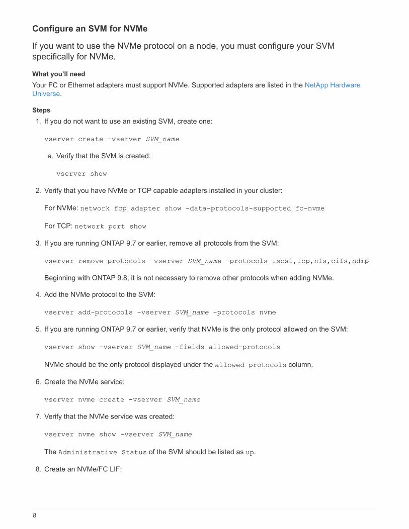
Configure an SVM for NVMe
If you want to use the NVMe protocol on a node, you must configure your SVM
specifically for NVMe.
What you’ll need
Your FC or Ethernet adapters must support NVMe. Supported adapters are listed in the NetApp Hardware
Universe.
Steps
1. If you do not want to use an existing SVM, create one:
vserver create -vserver SVM_name
a. Verify that the SVM is created:
vserver show
2. Verify that you have NVMe or TCP capable adapters installed in your cluster:
For NVMe: network fcp adapter show -data-protocols-supported fc-nvme
For TCP: network port show
3. If you are running ONTAP 9.7 or earlier, remove all protocols from the SVM:
vserver remove-protocols -vserver SVM_name -protocols iscsi,fcp,nfs,cifs,ndmp
Beginning with ONTAP 9.8, it is not necessary to remove other protocols when adding NVMe.
4. Add the NVMe protocol to the SVM:
vserver add-protocols -vserver SVM_name -protocols nvme
5. If you are running ONTAP 9.7 or earlier, verify that NVMe is the only protocol allowed on the SVM:
vserver show -vserver SVM_name -fields allowed-protocols
NVMe should be the only protocol displayed under the allowed protocols column.
6. Create the NVMe service:
vserver nvme create -vserver SVM_name
7. Verify that the NVMe service was created:
vserver nvme show -vserver SVM_name
The Administrative Status of the SVM should be listed as up.
8. Create an NVMe/FC LIF:
8

ONTAP version Applicable protocols Command
ONTAP 9.9.1 or earlier FC network interface create
-vserver SVM_name -lif
lif_name -role data -data
-protocol fc-nvme -home
-node home_node -home
-port home_port
ONTAP 9.10.1 FC or TCP network interface create
-vserver SVM_name -lif
lif_name -service-policy
{default-data-nvme-tcp |
default-data-nvme-fc}
-home-node home_node
-home-port home_port
-status admin up
-failover-policy disabled
-firewall-policy data
-auto-revert false
-failover-group
failover_group -is-dns
-update-enabled false
9. Create an NVMe/FC LIF on the HA partner node:
ONTAP version Applicable protocols Command
ONTAP 9.9.1 or earlier FC network interface create
-vserver SVM_name -lif
lif_name -role data -data
-protocol fc-nvme -home
-node home_node -home
-port home_port
ONTAP 9.10.1 or later FC or TCP network interface create
-vserver SVM_name -lif
lif_name -service-policy
{default-data-nvme-tcp |
default-data-nvme-fc}
-home-node home_node
-home-port home_port
-status admin up
-failover-policy disabled
-firewall-policy data
-auto-revert false
-failover-group
failover_group -is-dns
-update-enabled false
9

10. Verify the NVMe/FC LIFs were created:
network interface show -vserver SVM_name
11. Create volume on the same node as the LIF:
vol create -vserver SVM_name -volume vol_name -aggregate aggregate_name -size
volume_size
If a warning message is displayed about the auto efficiency policy, it can be safely ignored.
Create an NVMe namespace and subsystem
For systems using the NVMe protocol, you must create one or more NVMe namespaces
and subsystems. Each namespace can then be mapped to an NVMe subsystem to allow
data access from your host system.
What you’ll need
The SVM must already be configured for NVMe.
Steps
1. Verify that the SVM is configured for NVMe:
vserver show -vserver SVM_name -fields allowed-protocols
NVMe should be displayed under the allowed-protocols column.
2. Create the NVMe namespace:
vserver nvme namespace create -vserver SVM_name -path path -size
size_of_namespace -ostype OS_type
3. Create the NVMe subsystem:
vserver nvme subsystem create -vserver SVM_name -subsystem name_of_subsystem
-ostype OS_type
4. Verify that the subsystem was created:
vserver nvme subsystem show -vserver SVM_name
The nvme subsystem should be displayed under the Subsystem column.
Map an NVMe namespace to a subsystem
You must map a namespace to a subsystem when using NVMe.
What you’ll need
• You must have configured an SVM for NVMe.
• You must have created an NVMe namespace and subsystem.
10

About this task
A namespace can only be mapped to a single subsystem.
Steps
1. Obtain the NQN from the host.
2. Add the host NQN to the subsystem:
vserver nvme subsystem host add -vserver SVM_name -subsystem subsystem_name
-host-nqn Host_NQN:subsystem.subsystem_name
3. Map the namespace to the subsystem:
vserver nvme subsystem map add -vserver SVM_name -subsystem subsystem_name
-path path
4. Verify that the namespace is mapped to the subsystem:
vserver nvme namespace show -vserver SVM_name -instance
The subsystem should be listed as the Attached subsystem.
Manage LUNs for FC and iSCSi
Increase the size of a LUN
The size to which you can increase your LUN varies depending upon your version of
ONTAP.
ONTAP version Maximum LUN size
ONTAP 9.8 and later • 128 TB for All SAN Arrays (ASAs)
• 16 TB for non-ASAs
ONTAP 9.5, 9.6, 9.7 16TB
ONTAP 9.4 or earlier 10 times the original LUN size, but not greater than
16TB
For example, if you create a 100 GB LUN, you can
only grow it to 1,000 GB.
You do not need to take the LUN offline to increase the size. However, after you have increased the size, you
must rescan the LUN on the host for the host to recognize the change in size.
See the Command Reference page for the lun resize command for more information about resizing a LUN.
Solaris LUNs cannot be resized.
Steps
1. Increase the size of the LUN:
11

lun resize -vserver vserver_name -volume volume_name -lun lun_name -size
lun_size
2. Verify the increased LUN size:
lun show -vserver vserver_name
ONTAP operations round down the actual maximum size of the LUN so it is slightly less than
the expected value. Also, actual LUN size might vary slightly based on the OS type of the
LUN. To obtain the exact resized value, run the following commands in advanced mode:
set -unit B
lun show -fields max-resize-size -volume volume_name -lun lun_name
3. Rescan the LUN on the host.
4. Follow your host documentation to make the newly created LUN size visible to the host file system.
Decrease the size of a LUN
Before you decrease the size of a LUN, the host needs to migrate the blocks containing
the LUN data into the boundary of the smaller LUN size. You should use a tool such as
SnapDrive for Windows to ensure that the LUN is properly decreased without truncating
blocks containing LUN data. Manually decreasing the size of your LUN is not
recommended.
About this task
After you decrease the size of your LUN, ONTAP automatically notifies the initiator that the LUN size has
decreased. However, additional steps might be required on your host for the host to recognize the new LUN
size. Check your host documentation for specific information about decreasing the size of the host file
structure.
Move a LUN
You can move a LUN across volumes within a storage virtual machine (SVM), but you
cannot move a LUN across SVMs. LUNs moved across volumes within an SVM are
moved immediately and without loss of connectivity.
What you’ll need
If your LUN is using Selective LUN Map (SLM), the SLM reporting nodes must have been modified to include
the destination node and its HA partner.
About this task
Storage efficiency features, such as deduplication, compression, and compaction are not preserved during a
LUN move. They must be reapplied after the LUN move is completed.
Data protection through Snapshot copies occurs at the volume level. Therefore, when you move a LUN, it falls
under the data protection scheme of the destination volume. If you do not have Snapshot copies established
for the destination volume, Snapshot copies of the LUN are not created. Also, all of the Snapshot copies of the
LUN stay in the original volume until those Snapshot copies are deleted.
12

You cannot move a LUN to the following volumes:
• A SnapMirror destination volume
• The SVM root volume
You cannot move the following types of LUNs:
• A LUN that has been created from a file
• A LUN that is in NVFail state
• A LUN that is in a load-sharing relationship
• A protocol-endpoint class LUN
For Solaris os_type LUNs that are 1 TB or larger, the host might experience a timeout during the
LUN move. For this LUN type, you should unmount the LUN before initiating the move.
System Manager procedure
Beginning with ONTAP 9.10.1, you can use System Manager to create a new volume when you move a single
LUN. In ONTAP 9.8 and 9.9.1, the volume to which you are moving your LUN must exist before you begin the
LUN move.
Steps
1. In System Manager, click Storage>LUNs.
2. Right click the LUN you want to move, then click and select Move LUN.
In ONTAP 9.10.1, select to move the LUN to An existing volume or to a New volume.
If you select to create a new volume, provide the volume specifications.
3. Click Move.
CLI procedure
Steps
1. Move the LUN:
lun move start.
During a very brief period, the LUN is visible on both the origin and destination volume. This is expected
and is resolved upon completion of the move.
2. Track the status of the move and verify successful completion:
lun move show.
Related information
• Selective LUN Map
• Modifying the SLM reporting-nodes list
13

Delete LUNs
You can delete a LUN from a storage virtual machine (SVM) if you no longer need the
LUN.
What you’ll need
The LUN must be unmapped from its igroup before you can delete it.
Steps
1. Verify that the application or host is not using the LUN.
2. Unmap the LUN from the igroup:
lun mapping delete
lun mapping delete -vserver vs5 -volume vo5 -lun lun5 -igroup igr5
3. Delete the LUN:
lun delete
lun delete -vserver vs5 -volume vol5 -lun lun5
4. Verify that you deleted the LUN:
lun show
lun show -vserver vs5
Vserver Path State Mapped Type Size
--------- ----------------- -------- ------- -------- ------
vs5 /vol/vol16/lun8 online mapped windows 10.00GB
Considerations for copying LUNs
There are considerations you should be aware of when copying a LUN.
Cluster administrators can copy a LUN across storage virtual machines (SVMs) within the cluster by using the
lun copy command. Cluster administrators must establish the storage virtual machine (SVM) peering
relationship using the vserver peer create command before an inter-SVM LUN copy operation is
performed. There must be enough space in the source volume for a SIS clone.
LUNs in Snapshot copies can be used as source LUNs for the lun copy command. When you copy a LUN
using the lun copy command, the LUN copy is immediately available for read and write access. The source
LUN is unchanged by creation of a LUN copy. Both the source LUN and the LUN copy exist as unique LUNs
with different LUN serial numbers. Changes made to the source LUN are not reflected in the LUN copy, and
changes made to the LUN copy are not reflected in the source LUN. The LUN mapping of the source LUN is
not copied to the new LUN; the LUN copy must be mapped.
Data protection through Snapshot copies occurs at the volume level. Therefore, if you copy a LUN to a volume
different from the volume of the source LUN, the destination LUN falls under the data protection scheme of the
14

destination volume. If you do not have Snapshot copies established for the destination volume, Snapshot
copies are not created of the LUN copy.
Copying LUNs is a nondisruptive operation.
You cannot copy the following types of LUNs:
• A LUN that has been created from a file
• A LUN that is in NVFAIL state
• A LUN that is in a load-sharing relationship
• A protocol-endpoint class LUN
Ways to limit LUN access with port sets and igroups
In addition to using Selective LUN Map (SLM), you can limit access to your LUNs through
igroups and port sets.
Port sets can be used with SLM to further restrict access of certain targets to certain initiators. When using
SLM with port sets, LUNs will be accessible on the set of LIFs in the port set on the node that owns the LUN
and on that node’s HA partner.
In the following example, initiator1 does not have a port set. Without a port set, initiator1 can access LUN1
through both LIF1 and LIF2.
You can limit access to LUN1 by using a port set. In the following example, initiator1 can access LUN1 only
through LIF1. However, initiator1 cannot access LUN1 through LIF2 because LIF2 is not in port set1.
Related information
• Selective LUN Map
• Create port sets and binding igroups to port sets
Examine configured and used space of a LUN
Knowing the configured space and actual space used for your LUNs can help you
determine the amount of space that can be reclaimed when doing space reclamation, the
amount of reserved space that contains data, and the total configured size versus the
15

actual size used for a LUN.
Step
1. View the configured space versus the actual space used for a LUN:
lun show
The following example show the configured space versus the actual space used by the LUNs in the vs3
storage virtual machine (SVM):
lun show -vserver vs3 -fields path, size, size-used, space-reserve
vserver path size space-reserve size-used
------- ----------------- ------- ------------- ---------
vs3 /vol/vol0/lun1 50.01GB disabled 25.00GB
vs3 /vol/vol0/lun1_backup 50.01GB disabled 32.15GB
vs3 /vol/vol0/lun2 75.00GB disabled 0B
vs3 /vol/volspace/lun0 5.00GB enabled 4.50GB
4 entries were displayed.
Control and monitor I/O performance to LUNs by using Storage QoS
You can control input/output (I/O) performance to LUNs by assigning LUNs to Storage
QoS policy groups. You might control I/O performance to ensure that workloads achieve
specific performance objectives or to throttle a workload that negatively impacts other
workloads.
About this task
Policy groups enforce a maximum throughput limit (for example, 100 MB/s). You can create a policy group
without specifying a maximum throughput, which enables you to monitor performance before you control the
workload.
You can also assign storage virtual machines (SVMs) with FlexVol volumes and LUNs to policy groups.
Note the following requirements about assigning a LUN to a policy group:
• The LUN must be contained by the SVM to which the policy group belongs.
You specify the SVM when you create the policy group.
• If you assign a LUN to a policy group, then you cannot assign the LUN’s containing volume or SVM to a
policy group.
For more information about how to use Storage QoS, see the System administration reference.
Steps
1. Use the qos policy-group create command to create a policy group.
2. Use the lun create command or the lun modify command with the -qos-policy-group parameter
to assign a LUN to a policy group.
16

3. Use the qos statistics commands to view performance data.
4. If necessary, use the qos policy-group modify command to adjust the policy group’s maximum
throughput limit.
Tools available to effectively monitor your LUNs
Tools are available to help you effectively monitor your LUNs and avoid running out of
space.
• Active IQ Unified Manager is a free tool that enables you to manage all storage across all clusters in your
environment.
• System Manager is a graphical user interface built into ONTAP that enables you to manually manage
storage needs at the cluster level.
• OnCommand Insight presents a single view of your storage infrastructure and enables you to set up
automatic monitoring, alerts, and reporting when your LUNs, volumes, and aggregates are running out of
storage space.
Considerations for transitioning SAN configurations
In a SAN environment, a disruption in service is required during the transition of a 7-Mode
volume to ONTAP. You need to shut down your hosts to complete the transition. After
transition, you must update your host configurations before you can begin serving data in
ONTAP
You need to schedule a maintenance window during which you can shut down your hosts and complete the
transition.
Capabilities and restrictions of transitioned LUNs
LUNs that have been transitioned from Data ONTAP operating in 7-Mode to ONTAP have certain capabilities
and restrictions that affect the way the LUNs can be managed.
You can do the following with transitioned LUNs:
• View the LUN using the lun show command
• View the inventory of LUNs transitioned from the 7-Mode volume using the transition 7-mode show
command
• Restore a volume from a 7-Mode Snapshot copy
Restoring the volume transitions all of the LUNs captured in the Snapshot copy
• Restore a single LUN from a 7-Mode Snapshot copy using the snapshot restore-file command
• Create a clone of a LUN in a 7-Mode Snapshot copy
• Restore a range of blocks from a LUN captured in a 7-Mode Snapshot copy
• Create a FlexClone of the volume using a 7-Mode Snapshot copy
You cannot do the following with transitioned LUNs:
17
• Access Snapshot copy-backed LUN clones captured in the volume
Related information
Copy-based transition
I/O misalignments on properly aligned LUNs overview
ONTAP might report I/O misalignments on properly aligned LUNs. In general, these
misalignment warnings can be disregarded as long as you are confident that your LUN is
properly provisioned and your partitioning table is correct.
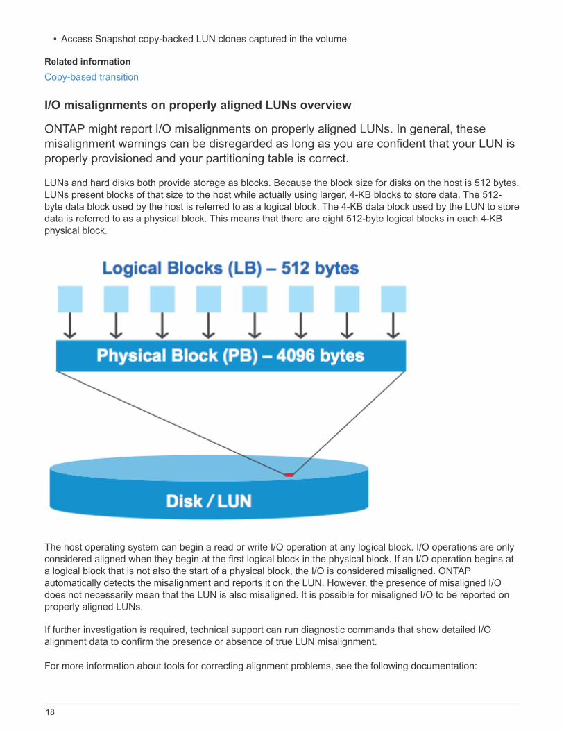
LUNs and hard disks both provide storage as blocks. Because the block size for disks on the host is 512 bytes,
LUNs present blocks of that size to the host while actually using larger, 4-KB blocks to store data. The 512-
byte data block used by the host is referred to as a logical block. The 4-KB data block used by the LUN to store
data is referred to as a physical block. This means that there are eight 512-byte logical blocks in each 4-KB
physical block.
The host operating system can begin a read or write I/O operation at any logical block. I/O operations are only
considered aligned when they begin at the first logical block in the physical block. If an I/O operation begins at
a logical block that is not also the start of a physical block, the I/O is considered misaligned. ONTAP
automatically detects the misalignment and reports it on the LUN. However, the presence of misaligned I/O
does not necessarily mean that the LUN is also misaligned. It is possible for misaligned I/O to be reported on
properly aligned LUNs.
If further investigation is required, technical support can run diagnostic commands that show detailed I/O
alignment data to confirm the presence or absence of true LUN misalignment.
For more information about tools for correcting alignment problems, see the following documentation:
18

• Windows Unified Host Utilities 7.1
• Virtual Storage Console for VMware vSphere Installation and Administration Guide
Achieve I/O alignment using LUN OS types
To achieve I/O alignment with your OS partitioning scheme, you should use the recommended ONTAP LUN
ostype value that most closely matches your operating system.
The partition scheme employed by the host operating system is a major contributing factor to I/O
misalignments. Some ONTAP LUN ostype values use a special offset known as a “prefix” to enable the
default partitioning scheme used by the host operating system to be aligned.
In some circumstances, a custom partitioning table might be required to achieve I/O alignment.
However, for ostype values with a “prefix” value greater than 0, a custom partition might create
misaligned I/O.
The LUN ostype values in the following table should be used based on your operating system.
LUN ostype Prefix (bytes) Prefix (sectors) Operating system
windows 32,256 63 Windows 2000, 2003
(MBR format)
windows_gpt 17,408 34 Windows 2003 (GPT
format)
windows_2008 0 0 Windows 2008 and later
linux 0 0 All Linux distributions
xen 0 0 Citrix XenServer
vmware 0 0 VMware ESX
solaris 1MB 2,048 Solaris
solaris_efi 17,408 34 Solaris
hpux 0 0 HP-UX
aix 0 0 AIX
Special I/O alignment considerations for Linux
Linux distributions offer a wide variety of ways to use a LUN including as raw devices for databases, various
volume managers, and file systems. It is not necessary to create partitions on a LUN when used as a raw
device or as physical volume in a logical volume.
19

For RHEL 5 and earlier and SLES 10 and earlier, if the LUN will be used without a volume manager, you
should partition the LUN to have one partition that begins at an aligned offset, which is a sector that is an even
multiple of eight logical blocks.
Special I/O alignment considerations for Solaris LUNs
You need to consider various factors when determining whether you should use the solaris ostype or the
solaris_efi ostype.
See the Solaris Host Utilities Installation and Administration Guide for detailed information.
ESX boot LUNs report as misaligned
LUNs used as ESX boot LUNs are typically reported by ONTAP as misaligned. ESX creates multiple partitions
on the boot LUN, making it very difficult to align. Misaligned ESX boot LUNs are not typically a performance
problem because the total amount of misaligned I/O is small. Assuming that the LUN was correctly provisioned
with the VMware ostype, no action is needed.
Related information
Guest VM file system partition/disk alignment for VMware vSphere, other virtual environments, and NetApp
storage systems
Ways to address issues when LUNs go offline
When no space is available for writes, LUNs go offline to preserve data integrity. LUNs
can run out of space and go offline for various reasons, and there are several ways you
can address the issue.
If the… You can…
Aggregate is full • Add more disks.
• Use the volume modify command to shrink a
volume that has available space.
• If you have space-guarantee volumes that have
available space, change the volume space
guarantee to none with the volume modify
command.
20
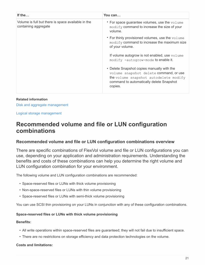
If the… You can…
Volume is full but there is space available in the
containing aggregate
• For space guarantee volumes, use the volume
modify command to increase the size of your
volume.
• For thinly provisioned volumes, use the volume
modify command to increase the maximum size
of your volume.
If volume autogrow is not enabled, use volume
modify -autogrow-mode to enable it.
• Delete Snapshot copies manually with the
volume snapshot delete command, or use
the volume snapshot autodelete modify
command to automatically delete Snapshot
copies.
Related information
Disk and aggregate management
Logical storage management
Recommended volume and file or LUN configurationcombinations
Recommended volume and file or LUN configuration combinations overview
There are specific combinations of FlexVol volume and file or LUN configurations you can
use, depending on your application and administration requirements. Understanding the
benefits and costs of these combinations can help you determine the right volume and
LUN configuration combination for your environment.
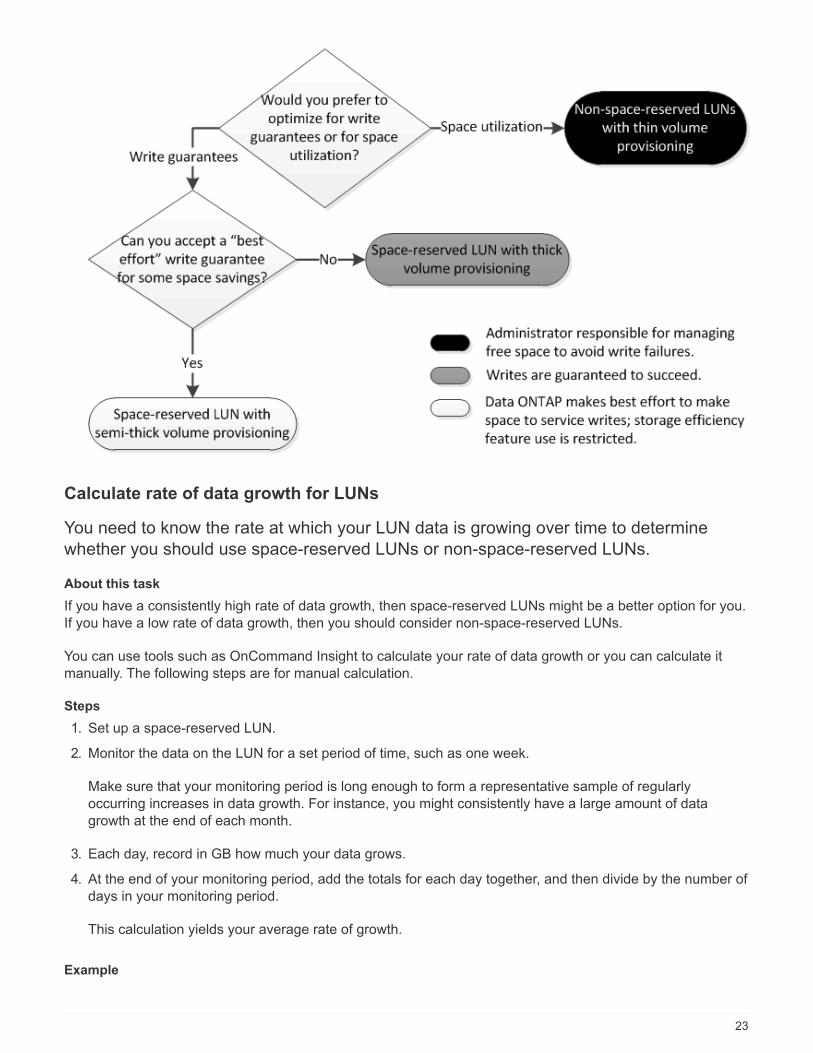
The following volume and LUN configuration combinations are recommended:
• Space-reserved files or LUNs with thick volume provisioning
• Non-space-reserved files or LUNs with thin volume provisioning
• Space-reserved files or LUNs with semi-thick volume provisioning
You can use SCSI thin provisioning on your LUNs in conjunction with any of these configuration combinations.
Space-reserved files or LUNs with thick volume provisioning
Benefits:
• All write operations within space-reserved files are guaranteed; they will not fail due to insufficient space.
• There are no restrictions on storage efficiency and data protection technologies on the volume.
Costs and limitations:
21

• Enough space must be set aside from the aggregate up front to support the thickly provisioned volume.
• Space equal to twice the size of the LUN is allocated from the volume at LUN creation time.
Non-space-reserved files or LUNs with thin volume provisioning
Benefits:
• There are no restrictions on storage efficiency and data protection technologies on the volume.
• Space is allocated only as it is used.
Costs and restrictions:
• Write operations are not guaranteed; they can fail if the volume runs out of free space.
• You must manage the free space in the aggregate effectively to prevent the aggregate from running out of
free space.
Space-reserved files or LUNs with semi-thick volume provisioning
Benefits:
Less space is reserved up front than for thick volume provisioning, and a best-effort write guarantee is still
provided.
Costs and restrictions:
• Write operations can fail with this option.
You can mitigate this risk by properly balancing free space in the volume against data volatility.
• You cannot rely on retention of data protection objects such as Snapshot copies and FlexClone files and
LUNs.
• You cannot use ONTAP block-sharing storage efficiency capabilities that cannot be automatically deleted,
including deduplication, compression, and ODX/Copy Offload.
Determine the correct volume and LUN configuration combination for yourenvironment
Answering a few basic questions about your environment can help you determine the
best FlexVol volume and LUN configuration for your environment.
About this task
You can optimize your LUN and volume configurations for maximum storage utilization or for the security of
write guarantees. Based on your requirements for storage utilization and your ability to monitor and replenish
free space quickly, you must determine the FlexVol volume and LUN volumes appropriate for your installation.
You do not need a separate volume for each LUN.
Step
1. Use the following decision tree to determine the best volume and LUN configuration combination for your
environment:
22
Calculate rate of data growth for LUNs
You need to know the rate at which your LUN data is growing over time to determine
whether you should use space-reserved LUNs or non-space-reserved LUNs.
About this task
If you have a consistently high rate of data growth, then space-reserved LUNs might be a better option for you.
If you have a low rate of data growth, then you should consider non-space-reserved LUNs.
You can use tools such as OnCommand Insight to calculate your rate of data growth or you can calculate it
manually. The following steps are for manual calculation.
Steps
1. Set up a space-reserved LUN.
2. Monitor the data on the LUN for a set period of time, such as one week.
Make sure that your monitoring period is long enough to form a representative sample of regularly
occurring increases in data growth. For instance, you might consistently have a large amount of data
growth at the end of each month.
3. Each day, record in GB how much your data grows.
4. At the end of your monitoring period, add the totals for each day together, and then divide by the number of
days in your monitoring period.
This calculation yields your average rate of growth.
Example
23

In this example, you need a 200 GB LUN. You decide to monitor the LUN for a week and record the following
daily data changes:
• Sunday: 20 GB
• Monday: 18 GB
• Tuesday: 17 GB
• Wednesday: 20 GB
• Thursday: 20 GB
• Friday: 23 GB
• Saturday: 22 GB
In this example, your rate of growth is (20+18+17+20+20+23+22) / 7 = 20 GB per day.
Configuration settings for space-reserved files or LUNs with thick-provisionedvolumes
This FlexVol volume and file or LUN configuration combination provides the ability to use
storage efficiency technologies and does not require you to actively monitor your free
space, because sufficient space is allocated up front.
The following settings are required to configure a space-reserved file or LUN in a volume using thick
provisioning:
Volume setting Value
Guarantee Volume
Fractional reserve 100
Snapshot reserve Any
Snapshot autodelete Optional
Autogrow Optional; if enabled, aggregate free space must be
actively monitored.
File or LUN setting Value
Space reservation Enabled
Configuration settings for non-space-reserved files or LUNs with thin-provisionedvolumes
This FlexVol volume and file or LUN configuration combination requires the smallest
amount of storage to be allocated up front, but requires active free space management to
prevent errors due to lack of space.
24

The following settings are required to configure a non-space-reserved files or LUN in a thin-provisioned
volume:
Volume setting Value
Guarantee None
Fractional reserve 0
Snapshot reserve Any
Snapshot autodelete Optional
Autogrow Optional
File or LUN setting Value
Space reservation Disabled
Additional considerations
When the volume or aggregate runs out of space, write operations to the file or LUN can fail.
If you do not want to actively monitor free space for both the volume and the aggregate, you should enable
Autogrow for the volume and set the maximum size for the volume to the size of the aggregate. In this
configuration, you must monitor aggregate free space actively, but you do not need to monitor the free space in
the volume.
Configuration settings for space-reserved files or LUNs with semi-thick volumeprovisioning
This FlexVol volume and file or LUN configuration combination requires less storage to be
allocated up front than the fully provisioned combination, but places restrictions on the
efficiency technologies you can use for the volume. Overwrites are fulfilled on a best-
effort basis for this configuration combination.
The following settings are required to configure a space-reserved LUN in a volume using semi-thick
provisioning:
Volume setting Value
Guarantee Volume
Fractional reserve 0
Snapshot reserve 0
25

Volume setting Value
Snapshot autodelete On, with a commitment level of destroy, a destroy list
that includes all objects, the trigger set to volume, and
all FlexClone LUNs and FlexClone files enabled for
automatic deletion.
Autogrow Optional; if enabled, aggregate free space must be
actively monitored.
File or LUN setting Value
Space reservation Enabled
Technology restrictions
You cannot use the following volume storage efficiency technologies for this configuration combination:
• Compression
• Deduplication
• ODX and FlexClone Copy Offload
• FlexClone LUNs and FlexClone files not marked for automatic deletion (active clones)
• FlexClone subfiles
• ODX/Copy Offload
Additional considerations
The following facts must be considered when employing this configuration combination:
• When the volume that supports that LUN runs low on space, protection data (FlexClone LUNs and files,
Snapshot copies) is destroyed.
• Write operations can time out and fail when the volume runs out of free space.
Compression is enabled by default for AFF platforms. You must explicitly disable compression for any volume
for which you want to use semi-thick provisioning on an AFF platform.
Selective LUN Map
Selective LUN Map overview
Selective LUN Map (SLM) reduces the number of paths from the host to the LUN. With
SLM, when a new LUN map is created, the LUN is accessible only through paths on the
node owning the LUN and its HA partner.
SLM enables management of a single igroup per host and also supports nondisruptive LUN move operations
that do not require portset manipulation or LUN remapping.
Portsets can be used with SLM just as in previous versions of ONTAP to further restrict access of certain
26

targets to certain initiators. When using SLM with portsets, LUNs will be accessible on the set of LIFs in the
portset on the node that owns the LUN and on that node’s HA partner.
SLM is enabled by default on all new LUN maps.
Determine whether SLM is enabled on a LUN map
If your environment has a combination of LUNs created in ONTAP and LUNs transitioned
from previous versions, you might need to determine whether Selective LUN Map (SLM)
is enabled on a specific LUN.
You can use the information displayed in the output of the lun mapping show -fields reporting-
nodes, node command to determine whether SLM is enabled on your LUN map. If SLM is not enabled, "-" is
displayed in the cells under the reporting-nodes column of the command output. If SLM is enabled, the list
of nodes displayed under the nodes column is duplicated in the reporting-nodes column.
Create port sets and binding igroups to port sets
In addition to using Selective LUN Map (SLM), you can create a port set and bind the port
set to an igroup to further limit which LIFs can be used by an initiator to access a LUN. If
you do not bind a port set to an igroup, then all of the initiators in the igroup can access
mapped LUNs through all of the LIFs on the node owning the LUN and the owning node’s
HA partner.
What you’ll need
You must have at least one LIF and one igroup.
Unless you are using interface groups, two LIFs are recommended for redundancy for both iSCSI and FC.
Only one LIF is recommended for interface groups.
About this task
It is advantageous to use ports sets with SLM when you have more than two LIFs on a node and you want to
restrict a certain initiator to a subset of LIFs. Without port sets, all targets on the node will be accessible by all
of the initiators with access to the LUN through the node owning the LUN and the owning node’s HA partner.
Steps
1. Create a port set containing the appropriate LIFs:
portset create -vserver vserver_name -portset portset_name -protocol protocol
-port-name port_name
If you are using FC, specify the protocol parameter as fcp. If you are using iSCSI, specify the
protocol parameter as iscsi.
2. Bind the igroup to the port set:
lun igroup bind -vserver vserver_name -igroup igroup_name -portset
portset_name
3. Verify that your port sets and LIFs are correct:
27

portset show -vserver vserver_name
Vserver Portset Protocol Port Names Igroups
--------- --------- -------- ------------- --------
vs3 portset0 iscsi lif0,lif1 igroup1
Modify the SLM reporting-nodes list
If you are moving a LUN or a volume containing LUNs to another high availability (HA)
pair within the same cluster, you should modify the Selective LUN Map (SLM) reporting-
nodes list before initiating the move to ensure that active, optimized LUN paths are
maintained.
Steps
1. Add the destination node and its partner node to the reporting-nodes list of the aggregate or volume:
lun mapping add-reporting-nodes -vserver vserver_name -path lun_path -igroup
igroup_name [-destination-aggregate aggregate_name|-destination-volume
volume_name]
If you have a consistent naming convention, you can modify multiple LUN mappings at the same time by
using -igroup instead of igroup.
2. Rescan the host to discover the newly added paths.
3. If your OS requires it, add the new paths to your multipath network I/O (MPIO) configuration.
4. Run the command for the needed move operation and wait for the operation to finish.
5. Verify that I/O is being serviced through the Active/Optimized path:
lun mapping show -fields reporting-nodes
6. Remove the previous LUN owner and its partner node from the reporting-nodes list:
lun mapping remove-reporting-nodes -vserver vserver_name -path lun_path
-igroup igroup_name -remote-nodes
7. Verify that the LUN has been removed from the existing LUN map:
lun mapping show -fields reporting-nodes
8. Remove any stale device entries for the host OS.
9. Change any multipathing configuration files if required.
10. Rescan the host to verify removal of old paths.
See your host documentation for specific steps to rescan your hosts.
Manage iSCSI protocol
28

Configure your network for best performance
Ethernet networks vary greatly in performance. You can maximize the performance of the
network used for iSCSI by selecting specific configuration values.
Steps
1. Connect the host and storage ports to the same network.
It is best to connect to the same switches. Routing should never be used.
2. Select the highest speed ports available, and dedicate them to iSCSI.
10 GbE ports are best. 1 GbE ports are the minimum.
3. Disable Ethernet flow control for all ports.
You should see the ONTAP 9 Network Management Guide for using the CLI to configure Ethernet port flow
control.
Network management
4. Enable jumbo frames (typically MTU of 9000).
All devices in the data path, including initiators, targets, and switches, must support jumbo frames.
Otherwise, enabling jumbo frames actually reduces network performance substantially.
Define a security policy method for an initiator
You can define a list of initiators and their authentication methods. You can also modify
the default authentication method that applies to initiators that do not have a user-defined
authentication method.
About this task
You can generate unique passwords using security policy algorithms in the product or you can manually
specify the passwords that you want to use.
Not all initiators support hexadecimal CHAP secret passwords.
Steps
1. Use the vserver iscsi security create command to create a security policy method for an
initiator.
vserver iscsi security create -vserver vs2 -initiator iqn.1991-
05.com.microsoft:host1 -auth-type CHAP -user-name bob1 -outbound-user-name
bob2
2. Follow the screen commands to add the passwords.
Creates a security policy method for initiator iqn.1991-05.com.microsoft:host1 with inbound and outbound
CHAP user names and passwords.
Related information
29

• How iSCSI authentication works
• Guidelines for using CHAP authentication
• What CHAP authentication is
Delete an iSCSI service for an SVM
You can delete an iSCSI service for a storage virtual machine (SVM) if it is no longer
required.
What you’ll need
The administration status of the iSCSI service must be in the “down” state before you can delete an iSCSI
service. You can move the administration status to down with the vserver iscsi modify command.
Steps
1. Use the vserver iscsi modify command to stop the I/O to the LUN.
vserver iscsi modify -vserver vs1 -status-admin down
2. Use the vserver iscsi delete command to remove the iscsi service from the SVM.
vserver iscsi delete -vserver vs_1
3. Use the vserver iscsi show command to verify that you deleted the iSCSI service from the SVM.
vserver iscsi show -vserver vs1
Get more details in iSCSI session error recoveries
Increasing the iSCSI session error recovery level enables you to receive more detailed
information about iSCSI error recoveries. Using a higher error recovery level might cause
a minor reduction in iSCSI session performance.
About this task
By default, ONTAP is configured to use error recovery level 0 for iSCSI sessions. If you are using an initiator
that has been qualified for error recovery level 1 or 2, you can choose to increase the error recovery level. The
modified session error recovery level affects only the newly created sessions and does not affect existing
sessions.
Beginning with ONTAP 9.4, the max-error-recovery-level option is not supported in the iscsi show
and iscsi modify commands.
Steps
1. Enter advanced mode:
set -privilege advanced
2. Verify the current setting by using the iscsi show command.
iscsi show -vserver vs3 -fields max-error-recovery-level
30

vserver max-error-recovery-level
------- ------------------------
vs3 0
3. Change the error recovery level by using the iscsi modify command.
iscsi modify -vserver vs3 -max-error-recovery-level 2
Register the SVM with an iSNS server
You can use the vserver iscsi isns command to configure the storage virtual
machine (SVM) to register with an iSNS server.
About this task
The vserver iscsi isns create command configures the SVM to register with the iSNS server. The
SVM does not provide commands that enable you to configure or manage the iSNS server. To manage the
iSNS server, you can use the server administration tools or the interface provided by the vendor for the iSNS
server.
Steps
1. On your iSNS server, ensure that your iSNS service is up and available for service.
2. Create the SVM management LIF on a data port:
network interface create -vserver SVM_name -lif lif_name -role data -data
-protocol none -home-node home_node_name -home-port home_port -address
IP_address -netmask network_mask
3. Create an iSCSI service on your SVM if one does not already exist:
vserver iscsi create -vserver SVM_name
4. Verify that the iSCSI service was created successfully:
iscsi show -vserver SVM_name
5. Verify that a default route exists for the SVM:
network route show -vserver SVM_name
6. If a default route does not exist for the SVM, create a default route:
network route create -vserver SVM_name -destination destination -gateway
gateway
7. Configure the SVM to register with the iSNS service:
vserver iscsi isns create -vserver SVM_name -address IP_address
Both IPv4 and IPv6 address families are supported. The address family of the iSNS server must be the
same as that of the SVM management LIF.
31

For example, you cannot connect anSVM management LIF with an IPv4 address to an iSNS server with an
IPv6 address.
8. Verify that the iSNS service is running:
vserver iscsi isns show -vserver SVM_name
9. If the iSNS service is not running, start it:
vserver iscsi isns start -vserver SVM_name
Resolve iSCSI error messages on the storage system
There are a number of common iSCSI-related error messages that you can view with the
event log show command. You need to know what these messages mean and what
you can do to resolve the issues they identify.
The following table contains the most common error messages, and instructions for resolving them:
Message Explanation What to do
ISCSI: network interface
identifier disabled for
use; incoming connection
discarded
The iSCSI service is not enabled
on the interface.You can use the iscsi
interface enable command to
enable the iSCSI service on the
interface. For example:
iscsi interface enable
-vserver vs1 -lif lif1
ISCSI: Authentication
failed for initiator
nodename
CHAP is not configured correctly
for the specified initiator.
You should check the CHAP
settings; you cannot use the same
user name and password for
inbound and outbound settings on
the storage system:
• Inbound credentials on the
storage system must match
outbound credentials on the
initiator.
• Outbound credentials on the
storage system must match
inbound credentials on the
initiator.
Troubleshoot iSCSI LUNs not visible on the host
The iSCSI LUNs appear as local disks to the host. If the storage system LUNs are not
available as disks on the host, you should verify the configuration settings.
32

Configuration setting What to do
Cabling Verify that the cables between the host and storage system are properly
connected.
Network connectivity Verify that there is TCP/IP connectivity between the host and storage system.
• From the storage system command line, ping the host interfaces that are
being used for iSCSI:
ping –node node_name -destination
host_ip_address_for_iSCSI
• From the host command line, ping the storage system interfaces that are
being used for iSCSI:
ping –node node_name -destination
host_ip_address_for_iSCSI
System requirements Verify that the components of your configuration are qualified. Also, verify that you
have the correct host operating system (OS) service pack level, initiator version,
ONTAP version, and other system requirements. The Interoperability Matrix
contains the most up-to-date system requirements.
Jumbo frames If you are using jumbo frames in your configuration, verify that jumbo frames are
enabled on all devices in the network path: the host Ethernet NIC, the storage
system, and any switches.
iSCSI service status Verify that the iSCSI service is licensed and started on the storage system.
Initiator login Verify that the initiator is logged in to the storage system. If the iscsi
initiator show command output shows no initiators are logged in, check the
initiator configuration on the host. Also verify that the storage system is configured
as a target of the initiator.
iSCSI node names (IQNs) Verify that you are using the correct initiator node names in the igroup
configuration. On the host, you can use the initiator tools and commands to
display the initiator node name. The initiator node names configured in the igroup
and on the host must match.
LUN mappings Verify that the LUNs are mapped to an igroup. On the storage system console,
you can use one of the following commands:
• lun mapping show displays all LUNs and the igroups to which they are
mapped.
• lun mapping show -igroup displays the LUNs mapped to a specific
igroup.
iSCSI LIFs enable Verify that the iSCSI logical interfaces are enabled.
33

Related information
NetApp Interoperability Matrix Tool
Manage FC protocol
Delete an FC service for an SVM
You can delete an FC service for a storage virtual machine (SVM) if it is no longer
required.
What you’ll need
The administration status must be “down” before you can delete a FC service for an SVM. You can set the
administration status to down with either the vserver fcp modify command or the vserver fcp stop
command.
Steps
1. Use the vserver fcp stop command to stop the I/O to the LUN.
vserver fcp stop -vserver vs_1
2. Use the vserver fcp delete command to remove the service from the SVM.
vserver fcp delete -vserver vs_1
3. Use the vserver fcp show to verify that you deleted the FC service from your SVM:
vserver fcp show -vserver vs_1
Recommended MTU configurations for FCoE jumbo frames
For Fibre Channel over Ethernet (FCoE), jumbo frames for the Ethernet adapter portion
of the CNA should be configured at 9000 MTU. Jumbo frames for the FCoE adapter
portion of the CNA should be configured at greater than 1500 MTU. Only configure jumbo
frames if the initiator, target, and all intervening switches support and are configured for
jumbo frames.
Manage systems with FC adapters
Manage systems with FC adapters
Commands are available to manage onboard FC adapters and FC adapter cards. These
commands can be used to configure the adapter mode, display adapter information, and
change the speed.
Most storage systems have onboard FC adapters that can be configured as initiators or targets. You can also
use FC adapter cards configured as initiators or targets. Initiators connect to back-end disk shelves, and
possibly foreign storage arrays (FlexArray). Targets connect only to FC switches. Both the FC target HBA ports
and the switch port speed should be set to the same value and should not be set to auto.
34

Related information
SAN configuration
Commands for managing FC adapters
You can use FC commands to manage FC target adapters, FC initiator adapters, and
onboard FC adapters for your storage controller. The same commands are used to
manage FC adapters for the FC protocol and the FC-NVMe protocol.
FC initiator adapter commands work only at the node level. You must use the run -node node_name
command before you can use the FC initiator adapter commands.
Commands for managing FC target adapters
If you want to… Use this command…
Display FC adapter information on a node network fcp adapter show
Modify FC target adapter parameters network fcp adapter modify
Display FC protocol traffic information run -node node_name sysstat -f
Display how long the FC protocol has been running run -node node_name uptime
Display adapter configuration and status run -node node_name sysconfig -v
adapter
Verify which expansion cards are installed and
whether there are any configuration errorsrun -node node_name sysconfig -ac
View a man page for a command man command_name
Commands for managing FC initiator adapters
If you want to… Use this command…
Display information for all initiators and their adapters
in a noderun -node node_name storage show
adapter
Display adapter configuration and status run -node node_name sysconfig -v
adapter
Verify which expansion cards are installed and
whether there are any configuration errorsrun -node node_name sysconfig -ac
35

Commands for managing onboard FC adapters
If you want to… Use this command…
Display the status of the onboard FC ports run -node node_name system hardware
unified-connect show
Configure FC adapters for initiator mode
You can configure individual FC ports of onboard adapters and certain FC adapter cards
for initiator mode. Initiator mode is used to connect the ports to tape drives, tape libraries,
or third-party storage with FlexArray Virtualization or Foreign LUN Import (FLI).
What you’ll need
• LIFs on the adapter must be removed from any port sets of which they are members.
• All LIF’s from every storage virtual machine (SVM) using the physical port to be modified must be migrated
or destroyed before changing the personality of the physical port from target to initiator.
About this task
Each onboard FC port can be individually configured as an initiator or a target. Ports on certain FC adapters
can also be individually configured as either a target port or an initiator port, just like the onboard FC ports. A
list of adapters that can be configured for target mode is available in the Hardware Universe.
NVMe/FC does support initiator mode.
Steps
1. Remove all LIFs from the adapter:
network interface delete -vserver SVM_name -lif LIF_name,LIF_name
2. Take your adapter offline:
network fcp adapter modify -node node_name -adapter adapter_port -status-admin
down
If the adapter does not go offline, you can also remove the cable from the appropriate adapter port on the
system.
3. Change the adapter from target to initiator:
system hardware unified-connect modify -t initiator adapter_port
4. Reboot the node hosting the adapter you changed.
5. Verify that the FC ports are configured in the correct state for your configuration:
system hardware unified-connect show
6. Bring the adapter back online:
node run -node node_name storage enable adapter adapter_port
36

Related information
NetApp Hardware Universe
Configure FC adapters for target mode
You can configure individual FC ports of onboard adapters and certain FC adapter cards
for target mode. Target mode is used to connect the ports to FC initiators.
About this task
Each onboard FC port can be individually configured as an initiator or a target. Ports on certain FC adapters
can also be individually configured as either a target port or an initiator port, just like the onboard FC ports. A
list of adapters that can be configured for target mode is available in the NetApp Hardware Universe.
The same steps are used when configuring FC adapters for the FC protocol and the FC-NVMe protocol.
However, only certain FC adapters support FC-NVMe. See the NetApp Hardware Universe for a list of
adapters that support the FC-NVMe protocol.
Steps
1. Take the adapter offline:
node run -node node_name storage disable adapter adapter_name
If the adapter does not go offline, you can also remove the cable from the appropriate adapter port on the
system.
2. Change the adapter from initiator to target:
system hardware unified-connect modify -t target -node node_name adapter
adapter_name
3. Reboot the node hosting the adapter you changed.
4. Verify that the target port has the correct configuration:
network fcp adapter show -node node_name
5. Bring your adapter online:
network fcp adapter modify -node node_name -adapter adapter_port -state up
Display information about an FC target adapter
You can use the network fcp adapter show command to display system
configuration and adapter information for any FC adapter in the system.
Step
1. Display information about the FC adapter by using the network fcp adapter show command.
The output displays system configuration information and adapter information for each slot that is used.
network fcp adapter show -instance -node node1 -adapter 0a
37

Change the UTA2 port from CNA mode to FC mode
You should change the UTA2 port from Converged Network Adapter (CNA) mode to Fibre
Channel (FC) mode to support the FC initiator and FC target mode. You should change
the personality from CNA mode to FC mode when you need to change the physical
medium that connects the port to its network.
Steps
1. Take the adapter offline:
network fcp adapter modify -node node_name -adapter adapter_name -status-admin
down
2. Change the port mode:
ucadmin modify -node node_name -adapter adapter_name -mode fcp
3. Reboot the node, and then bring the adapter online:
network fcp adapter modify -node node_name -adapter adapter_name -status-admin
up
4. Notify your admin or VIF manager to delete or remove the port, as applicable:
◦ If the port is used as a home port of a LIF, is a member of an interface group (ifgrp), or hosts VLANs,
then an admin should do the following:
i. Move the LIFs, remove the port from the ifgrp, or delete the VLANs, respectively.
ii. Manually delete the port by running the network port delete command.
If the network port delete command fails, the admin should address the errors, and then run
the command again.
◦ If the port is not used as the home port of a LIF, is not a member of an ifgrp, and does not host VLANs,
then the VIF manager should remove the port from its records at the time of reboot.
If the VIF manager does not remove the port, then the admin must remove it manually after the reboot
by using the network port delete command.
net-f8040-34::> network port show
Node: net-f8040-34-01
Speed(Mbps) Health
Port IPspace Broadcast Domain Link MTU Admin/Oper Status
--------- ------------ ---------------- ---- ---- -----------
--------
...
e0i Default Default down 1500 auto/10 -
e0f Default Default down 1500 auto/10 -
...
38

net-f8040-34::> ucadmin show
Current Current Pending Pending
Admin
Node Adapter Mode Type Mode Type
Status
------------ ------- ------- --------- ------- ---------
-----------
net-f8040-34-01 0e cna target - -
offline
net-f8040-34-01 0f cna target - -
offline
...
net-f8040-34::> network interface create -vs net-f8040-34 -lif m
-role
node-mgmt-home-node net-f8040-34-01 -home-port e0e -address 10.1.1.1
-netmask 255.255.255.0
net-f8040-34::> network interface show -fields home-port, curr-port
vserver lif home-port curr-port
------- --------------------- --------- ---------
Cluster net-f8040-34-01_clus1 e0a e0a
Cluster net-f8040-34-01_clus2 e0b e0b
Cluster net-f8040-34-01_clus3 e0c e0c
Cluster net-f8040-34-01_clus4 e0d e0d
net-f8040-34
cluster_mgmt e0M e0M
net-f8040-34
m e0e e0i
net-f8040-34
net-f8040-34-01_mgmt1 e0M e0M
7 entries were displayed.
net-f8040-34::> ucadmin modify local 0e fc
Warning: Mode on adapter 0e and also adapter 0f will be changed to
fc.
Do you want to continue? {y|n}: y
Any changes will take effect after rebooting the system. Use the
"system node reboot" command to reboot.
net-f8040-34::> reboot local
(system node reboot)
39

Warning: Are you sure you want to reboot node "net-f8040-34-01"?
{y|n}: y
5. Verify that you have the correct SFP+ installed:
network fcp adapter show -instance -node -adapter
For CNA, you should use a 10Gb Ethernet SFP. For FC, you should either use an 8 Gb SFP or a 16 Gb
SFP, before changing the configuration on the node.
Change the CNA/UTA2 target adapter optical modules
You should change the optical modules on the unified target adapter (CNA/UTA2) to
support the personality mode you have selected for the adapter.
Steps
1. Verify the current SFP+ used in the card. Then, replace the current SFP+ with the appropriate SFP+ for the
preferred personality (FC or CNA).
2. Remove the current optical modules from the X1143A-R6 adapter.
3. Insert the correct modules for your preferred personality mode (FC or CNA) optics.
4. Verify that you have the correct SFP+ installed:
network fcp adapter show -instance -node -adapter
Supported SFP+ modules and Cisco-branded Copper (Twinax) cables are listed in the Hardware Universe.
Related information
NetApp Hardware Universe
View adapter settings
To view the settings for your unified target adapter (X1143A-R6), you must run the
system hardware unified-connect show command to display all modules on
your controller.
Steps
1. Boot your controller without the cables attached.
2. Run the system hardware unified-connect show command to see the port configuration and
modules.
3. View the port information before configuring the CNA and ports.
Supported port configurations for X1143A-R6 adapters
The FC target mode is the default configuration for X1143A-R6 adapter ports. However,
ports on this adapter can be configured as either 10-Gb Ethernet and FCoE ports or as
16-Gb FC ports.
40

When configured for Ethernet and FCoE, X1143A-R6 adapters support concurrent NIC and FCoE target traffic
on the same 10-GBE port. When configured for FC, each two-port pair that shares the same ASIC can be
individually configured for FC target or FC initiator mode. This means that a single X1143A-R6 adapter can
support FC target mode on one two-port pair and FC initiator mode on another two-port pair.
Related information
NetApp Hardware Universe
SAN configuration
Configure the ports
To configure the unified target adapter (X1143A-R6), you must configure the two adjacent
ports on the same chip in the same personality mode.
Steps
1. Configure the ports as needed for Fibre Channel (FC) or Converged Network Adapter (CNA) using the
system node hardware unified-connect modify command.
2. Attach the appropriate cables for FC or 10 Gb Ethernet.
3. Verify that you have the correct SFP+ installed:
network fcp adapter show -instance -node -adapter
For CNA, you should use a 10Gb Ethernet SFP. For FC, you should either use an 8 Gb SFP or a 16 Gb
SFP, based on the FC fabric being connected to.
Prevent loss of connectivity when using the X1133A-R6 adapter
You can prevent loss of connectivity during a port failure by configuring your system with
redundant paths to separate X1133A-R6 HBAs.
The X1133A-R6 HBA is a 4-port, 16 Gb FC adapter consisting of two 2-port pairs. The X1133A-R6 adapter can
be configured as target mode or initiator mode. Each 2-port pair is supported by a single ASIC (for example,
Port 1 and Port 2 on ASIC 1 and Port 3 and Port 4 on ASIC 2). Both ports on a single ASIC must be configured
to operate in the same mode, either target mode or initiator mode. If an error occurs with the ASIC supporting a
pair, both ports in the pair go offline.
To prevent this loss of connectivity, you configure your system with redundant paths to separate X1133A-R6
HBAs, or with redundant paths to ports supported by different ASICs on the HBA.
Manage NVMe protocol
Manage NVMe
Beginning with ONTAP 9.4, NVMe/FC is supported. Beginning with ONTAP 9.5 a license
is required to support NVMe. If NVMe is enabled in ONTAP 9.4, a 90 day grace period is
given to acquire the license after upgrading to ONTAP 9.5.
You can enable the license using the following command:
41

system license add -license-code NVMe_license_key
Start the NVMe service for an SVM
Before you can use the NVMe protocol on your storage virtual machine (SVM), you must
start the NVMe service on the SVM.
Before you begin
NVMe must be allowed as a protocol on your system.
The following NVMe protocols are supported:
Protocol Beginning with … Allowed by…
TCP ONTAP 9.10.1 Default
FCP ONTAP 9.4 Default
Steps
1. Change the privilege setting to advanced:
set -privilege advanced
2. Verify that NVMe is allowed as a protocol:
vserver nvme show
3. Create the NVMe protocol service:
vserver nvme create
4. Start the NVMe protocol service on the SVM:
vserver nvme modify -status -admin up
Delete NVMe service from an SVM
If needed, you can delete the NVMe service from your storage virtual machine (SVM).
Steps
1. Change the privilege setting to advanced:
set -privilege advanced
2. Stop the NVMe service on the SVM:
vserver nvme modify -status -admin down
3. Delete the NVMe service:
vserver nvme delete
42

Resizing a namespace
Beginning with ONTAP 9.10.1, you can use the ONTAP CLI to increase or decrease the
size of a NVMe namespace. You can use System Manager to increase the size of a
NVMe namespace.
Increase the size of a namespace
Using System Manager Using the CLI
1. Click Storage > NVMe Namespaces.
2. Hoover over the namespace you want to
increase, click , and then click Edit.
3. Under CAPACITY, change the size of the
namespace.
1. Enter the following command: vserver nvme
namespace modify -vserver SVM_name
-path path –size
new_size_of_namespace
Decrease the size of a namespace
You must use the ONTAP CLI to decrease the size of a NVMe namespace.
1. Change the privilege setting to advanced:
set –privilege advanced
2. Decrease the size of the namespace:
vserver nvme namespace modify -vserver SVM_name -path namespace_path -size
new_size_of_namespace
Manage LIFs for all SAN protocols
Manage LIFs for all SAN protocols
LIFs are connected to the SAN hosts. They can be removed from port sets, moved to
different nodes within a storage virtual machine (SVM), and deleted.
Related information
Network management
Configure an NVMe LIF
Certain requirements must be met when configuring NVMe LIFs.
What you’ll need
NVMe must be supported by the FC adapter on which you create the LIF. Supported adapters are listed in the
Hardware Universe.
NetApp Hardware Universe
43

About this task
The following rules apply when creating an NVMe LIF:
• NVMe can be the only data protocol on data LIFs.
• You should configure one management LIF for every SVM that supports SAN.
• For ONTAP 9.5 and later:
◦ You can only configure two NVMe LIFs per node on a maximum of four nodes.
◦ You must configure an NVMe LIF on the node containing the namespace and on node’s HA partner.
• For ONTAP 9.4 only:
◦ NVMe LIFs and namespaces must be hosted on the same node.
◦ Only one NVMe data LIF can be configured per SVM.
Steps
1. Create the LIF:
network interface create -vserver SVM_name -lif LIF_name -role LIF_role -data
-protocol fc-nvme -home-node home_node -home-port
home_port
2. Verify that the LIF was created:
network interface show -vserver SVM_name
Considerations for SAN LIF movement
You only need to perform a LIF movement if you are changing the contents of your
cluster, for example, adding nodes to the cluster or deleting nodes from the cluster. If you
perform a LIF movement, you do not have to re-zone your FC fabric or create new iSCSI
sessions between the attached hosts of your cluster and the new target interface.
You cannot move a SAN LIF using the network interface move command. SAN LIF movement must be
performed by taking the LIF offline, moving the LIF to a different home node or port, and then bringing it back
online in its new location. Asymmetric Logical Unit Access (ALUA) provides redundant paths and automatic
path selection as part of any ONTAP SAN solution. Therefore, there is no I/O interruption when the LIF is taken
offline for the movement. The host simply retries and then moves I/O to another LIF.
Using LIF movement, you can nondisruptively do the following:
• Replace one HA pair of a cluster with an upgraded HA pair in a way that is transparent to hosts accessing
LUN data
• Upgrade a target interface card
• Shift the resources of a storage virtual machine (SVM) from one set of nodes in a cluster to another set of
nodes in the cluster
Remove a SAN LIF from a port set
If the LIF you want to delete or move is in a port set, you must remove the LIF from the
44
port set before you can delete or move the LIF.
About this task
You need to do Step 1 in the following procedure only if one LIF is in the port set. You cannot remove the last
LIF in a port set if the port set is bound to an initiator group. Otherwise, you can start with Step 2 if multiple
LIFs are in the port set.
Steps
1. If only one LIF is in the port set, use the lun igroup unbind command to unbind the port set from the
initiator group.
When you unbind an initiator group from a port set, all of the initiators in the initiator group
have access to all target LUNs mapped to the initiator group on all network interfaces.
cluster1::>lun igroup unbind -vserver vs1 -igroup ig1
2. Use the lun portset remove command to remove the LIF from the port set.
cluster1::> port set remove -vserver vs1 -portset ps1 -port-name lif1
Move a SAN LIF
If a node needs to be taken offline, you can move a SAN LIF to preserve its configuration
information, such as its WWPN, and avoid rezoning the switch fabric. Because a SAN LIF
must be taken offline before it is moved, host traffic must rely on host multipathing
software to provide nondisruptive access to the LUN. You can move SAN LIFs to any
node in a cluster, but you cannot move the SAN LIFs between storage virtual machines
(SVMs).
What you’ll need
If the LIF is a member of a port set, the LIF must have been removed from the port set before the LIF can be
moved to a different node.
About this task
The destination node and physical port for a LIF that you want to move must be on the same FC fabric or
Ethernet network. If you move a LIF to a different fabric that has not been properly zoned, or if you move a LIF
to an Ethernet network that does not have connectivity between iSCSI initiator and target, the LUN will be
inaccessible when you bring it back online.
Steps
1. View the administrative and operational status of the LIF:
network interface show -vserver vserver_name
2. Change the status of the LIF to down (offline):
network interface modify -vserver vserver_name -lif LIF_name -status-admin
down
3. Assign the LIF a new node and port:
45
network interface modify -vserver vserver_name -lif LIF_name -home-node
node_name -home-port port_name
4. Change the status of the LIF to up (online):
network interface modify -vserver vserver_name -lif LIF_name -status-admin up
5. Verify your changes:
network interface show -vserver vserver_name
Delete a LIF in a SAN environment
Before you delete a LIF, you should ensure that the host connected to the LIF can access
the LUNs through another path.
What you’ll need
If the LIF you want to delete is a member of a port set, you must first remove the LIF from the port set before
you can delete the LIF.
Steps
1. Verify the name of the LIF and current port to be deleted:
network interface show –vserver vserver_name
2. Delete the LIF:
network interface delete
network interface delete -vserver vs1 -lif lif1
3. Verify that you deleted the LIF:
network interface show
network interface show -vserver vs1
Logical Status Network Current Current Is
Vserver Interface Admin/Oper Address/Mask Node Port Home
------- ---------- ---------- ---------------- --------- ------- ----
vs1
lif2 up/up 192.168.2.72/24 node-01 e0b true
lif3 up/up 192.168.2.73/24 node-01 e0b true
Considerations for adding nodes to a cluster
You need to be aware of certain considerations when adding nodes to a cluster.
46

• You must create LIFs on the new nodes as appropriate before you create LUNs on those new nodes.
• You must discover those LIFs from the hosts as dictated by the host stack and protocol.
• You must create LIFs on the new nodes so that the LUN and volume movements are possible without
using the cluster interconnect network.
Configure iSCSI LIFs to return FQDN to host iSCSI SendTargets DiscoveryOperation
Beginning with ONTAP 9, iSCSI LIFs can be configured to return a Fully Qualified
Domain Name (FQDN) when a host OS sends an iSCSI SendTargets Discovery
Operation. Returning a FQDN is useful when there is a Network Address Translation
(NAT) device between the host OS and the storage service.
About this task
IP addresses on one side of the NAT device are meaningless on the other side, but FQDNs can have meaning
on both sides.
The FQDN value interoperability limit is 128 characters on all host OS.
Steps
1. Change the privilege setting to advanced:
set -privilege advanced
2. Configure iSCSI LIFs to return FQDN:
vserver iscsi interface modify -vserver SVM_name -lif iscsi_LIF_name
-sendtargets_fqdn FQDN
In the following example, the iSCSI LIFs are configured to return storagehost-005.example.com as the
FQDN.
vserver iscsi interface modify -vserver vs1 -lif vs1_iscsi1 -sendtargets-fqdn
storagehost-005.example.com
3. Verify that sendtargets is the FQDN:
vserver iscsi interface show -vserver SVM_name -fields sendtargets-fqdn
In this example, storagehost-005.example.com is displayed in the sendtargets-fqdn output field.
cluster::vserver*> vserver iscsi interface show -vserver vs1 -fields
sendtargets-fqdn
vserver lif sendtargets-fqdn
------- ---------- ---------------------------
vs1 vs1_iscsi1 storagehost-005.example.com
vs1 vs1_iscsi2 storagehost-006.example.com
47

Related information
ONTAP 9 commands
Data protection methods in SAN environments
Data protection methods in SAN environments overview
You can protect your data by making copies of it so that it is available for restoration in
the event of accidental deletion, application crashes, data corruption, or disaster.
Depending on your data protection and backup needs, ONTAP offers a variety of
methods that enable you to protect your data.
SnapMirror Business Continuity (SM-BC)
Beginning with general availability in ONTAP 9.9.1, provides Zero Recovery Time Objective (Zero RTO) or
Transparent Application Failover (TAF) to enable automatic failover of business-critical applications in SAN
environments. SM-BC requires the installation of ONTAP Mediator 1.2 in a configuration with either two AFF
clusters or two All SAN Array (ASA) clusters.
NetApp Documentation: SnapMirror Business Continuity
Snapshot copy
Enables you to manually or automatically create, schedule, and maintain multiple backups of your LUNs.
Snapshot copies use only a minimal amount of additional volume space and do not have a performance cost. If
your LUN data is accidentally modified or deleted, that data can easily and quickly be restored from one of the
latest Snapshot copies.
FlexClone LUNs (FlexClone license required)
Provides point-in-time, writable copies of another LUN in an active volume or in a Snapshot copy. A clone and
its parent can be modified independently without affecting each other.
SnapRestore (license required)
Enables you to perform fast, space-efficient, on-request data recovery from Snapshot copies on an entire
volume. You can use SnapRestore to restore a LUN to an earlier preserved state without rebooting the storage
system.
Data protection mirror copies (SnapMirror license required)
Provides asynchronous disaster recovery by enabling you to periodically create Snapshot copies of data on
your volume; copy those Snapshot copies over a local or wide area network to a partner volume, usually on
another cluster; and retain those Snapshot copies. The mirror copy on the partner volume provides quick
availability and restoration of data from the time of the last Snapshot copy, if the data on the source volume is
corrupted or lost.
SnapVault backups (SnapMirror license required)
Provides storage efficient and long-term retention of backups. SnapVault relationships enable you to back up
selected Snapshot copies of volumes to a destination volume and retain the backups.
48

If you conduct tape backups and archival operations, you can perform them on the data that is already backed
up on the SnapVault secondary volume.
SnapDrive for Windows or UNIX (SnapDrive license required)
Configures access to LUNs, manages LUNs, and manages storage system Snapshot copies directly from a
Windows or UNIX hosts.
Native tape backup and recovery
Support for most existing tape drives are included in ONTAP, as well as a method for tape vendors to
dynamically add support for new devices. ONTAP also supports the Remote Magnetic Tape (RMT) protocol,
enabling backup and recovery to any capable system.
Related information
NetApp Documentation: SnapDrive for UNIX
NetApp Documentation: SnapDrive for Windows (current releases)
Data protection using tape backup
Effect of moving or copying a LUN on Snapshot copies
Effect of moving or copying a LUN on Snapshot copies overview
Snapshot copies are created at the volume level. If you copy or move a LUN to a different
volume, the Snapshot copy policy of the destination volune is applied to the copied or
moved volume. If Snapshot copies are not eestablished for the destination volume,
Snapshot copies will not be created of the moved or copied LUN.
Restore a single LUN from a Snapshot copy
You can restore a single LUN from a Snapshot copy without restoring the entire volume
that contains the single LUN. You can restore the LUN in place or to a new path in the
volume. The operation restores only the single LUN without impacting other files or LUNs
in the volume. You can also restore files with streams.
What you’ll need
• You must have enough space on your volume to complete the restore operation:
◦ If you are restoring a space-reserved LUN where the fractional reserve is 0%, you require one times
the size of the restored LUN.
◦ If you are restoring a space-reserved LUN where the fractional reserve is 100%, you require two times
the size of the restored LUN.
◦ If you are restoring a non-space-reserved LUN, you only require the actual space used for the restored
LUN.
• A Snapshot copy of the destination LUN must have been created.
If the restore operation fails, the destination LUN might be truncated. In such cases, you can use the
Snapshot copy to prevent data loss.
49

• A Snapshot copy of the source LUN must have been created.
In rare cases, the LUN restore can fail, leaving the source LUN unusable. If this occurs, you can use the
Snapshot copy to return the LUN to the state just before the restore attempt.
• The destination LUN and source LUN must have the same OS type.
If your destination LUN has a different OS type from your source LUN, your host can lose data access to
the destination LUN after the restore operation.
Steps
1. From the host, stop all host access to the LUN.
2. Unmount the LUN on its host so that the host cannot access the LUN.
3. Unmap the LUN:
lun mapping delete -vserver vserver_name -volume volume_name -lun lun_name
-igroup igroup_name
4. Determine the Snapshot copy you want to restore your LUN to:
volume snapshot show -vserver vserver_name -volume volume_name
5. Create a Snapshot copy of the LUN prior to restoring the LUN:
volume snapshot create -vserver vserver_name -volume volume_name -snapshot
snapshot_name
6. Restore the specified LUN in a volume:
volume snapshot restore-file -vserver vserver_name -volume volume_name
-snapshot snapshot_name -path lun_path
7. Follow the steps on the screen.
8. If necessary, bring the LUN online:
lun modify -vserver vserver_name -path lun_path -state online
9. If necessary, remap the LUN:
lun mapping create -vserver vserver_name -volume volume_name -lun lun_name
-igroup igroup_name
10. From the host, remount the LUN.
11. From the host, restart access to the LUN.
Restore all LUNs in a volume from a Snapshot copy
You can use volume snapshot restore command to restore all the LUNs in a
specified volume from a Snapshot copy.
Steps
50
1. From the host, stop all host access to the LUNs.
Using SnapRestore without stopping all host access to LUNs in the volume can cause data corruption and
system errors.
2. Unmount the LUNs on that host so that the host cannot access the LUNs.
3. Unmap your LUNs:
lun mapping delete -vserver vserver_name -volume volume_name -lun lun_name
-igroup igroup_name
4. Determine the Snapshot copy to which you want to restore your volume:
volume snapshot show -vserver vserver_name -volume volume_name
5. Change your privilege setting to advanced:
set -privilege advanced
6. Restore your data:
volume snapshot restore -vserver vserver_name -volume volume_name -snapshot
snapshot_name
7. Follow the instructions on the screen.
8. Remap your LUNs:
lun mapping create -vserver vserver_name -volume volume_name -lun lun_name
-igroup igroup_name
9. Verify that your LUNs are online:
lun show -vserver vserver_name -path lun_path -fields state
10. If your LUNs are not online, bring them online:
lun modify -vserver vserver_name -path lun_path -state online
11. Change your privilege setting to admin:
set -privilege admin
12. From the host, remount your LUNs.
13. From the host, restart access to your LUNs.
Delete one or more existing Snapshot copies from a volume
You can manually delete one or more existing Snapshot copies from the volume. You
might want to do this if you need more space on your volume.
Steps
1. Use the volume snapshot show command to verify which Snapshot copies you want to delete.
51

cluster::> volume snapshot show -vserver vs3 -volume vol3
---Blocks---
Vserver Volume Snapshot Size Total% Used%
-------- ------- ----------------------- ----- ------ -----
vs3 vol3
snap1.2013-05-01_0015 100KB 0% 38%
snap1.2013-05-08_0015 76KB 0% 32%
snap2.2013-05-09_0010 76KB 0% 32%
snap2.2013-05-10_0010 76KB 0% 32%
snap3.2013-05-10_1005 72KB 0% 31%
snap3.2013-05-10_1105 72KB 0% 31%
snap3.2013-05-10_1205 72KB 0% 31%
snap3.2013-05-10_1305 72KB 0% 31%
snap3.2013-05-10_1405 72KB 0% 31%
snap3.2013-05-10_1505 72KB 0% 31%
10 entries were displayed.
2. Use the volume snapshot delete command to delete all of the Snapshot copies.
cluster::> volume snapshot delete -vserver vs3 -volume vol3 *
10 entries were acted on.
Use FlexClone LUNs to protect your data
Use FlexClone LUNs to protect your data overview
A FlexClone LUN is a point-in-time, writeable copy of another LUN in an active volume or
in a Snapshot copy. The clone and its parent can be modified independently without
affecting each other.
A FlexClone LUN shares space initially with its parent LUN. By default, the FlexClone LUN inherits the space-
reserved attribute of the parent LUN. For example, if the parent LUN is non-space-reserved, the FlexClone
LUN is also non-space-reserved by default. However, you can create a non-space-reserved FlexClone LUN
from a parent that is a space-reserved LUN.
When you clone a LUN, block sharing occurs in the background and you cannot create a volume Snapshot
copy until the block sharing is finished.
You must configure the volume to enable the FlexClone LUN automatic deletion function with the volume
snapshot autodelete modify command. Otherwise, if you want FlexClone LUNs to be deleted
automatically but the volume is not configured for FlexClone auto delete, none of the FlexClone LUNs are
deleted.
When you create a FlexClone LUN, the FlexClone LUN automatic deletion function is disabled by default. You
52

must manually enable it on every FlexClone LUN before that FlexClone LUN can be automatically deleted. If
you are using semi-thick volume provisioning and you want the “best effort” write guarantee provided by this
option, you must make all FlexClone LUNs available for automatic deletion.
When you create a FlexClone LUN from a Snapshot copy, the LUN is automatically split from
the Snapshot copy by using a space-efficient background process so that the LUN does not
continue to depend on the Snapshot copy or consume any additional space. If this background
split has not been completed and this Snapshot copy is automatically deleted, that FlexClone
LUN is deleted even if you have disabled the FlexClone auto delete function for that FlexClone
LUN. After the background split is complete, the FlexClone LUN is not deleted even if that
Snapshot copy is deleted.
Related information
Logical storage management
Reasons for using FlexClone LUNs
You can use FlexClone LUNs to create multiple read/write copies of a LUN.
You might want to do this for the following reasons:
• You need to create a temporary copy of a LUN for testing purposes.
• You need to make a copy of your data available to additional users without giving them access to the
production data.
• You want to create a clone of a database for manipulation and projection operations, while preserving the
original data in an unaltered form.
• You want to access a specific subset of a LUN’s data (a specific logical volume or file system in a volume
group, or a specific file or set of files in a file system) and copy it to the original LUN, without restoring the
rest of the data in the original LUN. This works on operating systems that support mounting a LUN and a
clone of the LUN at the same time. SnapDrive for UNIX supports this with the snap connect command.
• You need multiple SAN boot hosts with the same operating system.
How a FlexVol volume can reclaim free space with autodelete setting
You can enable the autodelete setting of a FlexVol volume to automatically delete
FlexClone files and FlexClone LUNs. By enabling autodelete, you can reclaim a target
amount of free space in the volume when a volume is nearly full.
You can configure a volume to automatically start deleting FlexClone files and FlexClone LUNs when the free
space in the volume decreases below a particular threshold value, and automatically stop deleting clones when
a target amount of free space in the volume is reclaimed. Although, you cannot specify the threshold value that
starts the automatic deletion of clones, you can specify whether a clone is eligible for deletion, and you can
specify the target amount of free space for a volume.
A volume automatically deletes FlexClone files and FlexClone LUNs when the free space in the volume
decreases below a particular threshold and when both of the following requirements are met:
• The autodelete capability is enabled for the volume that contains the FlexClone files and FlexClone LUNs.
You can enable the autodelete capability for a FlexVol volume by using the volume snapshot
autodelete modify command. You must set the -trigger parameter to volume or snap_reserve
53
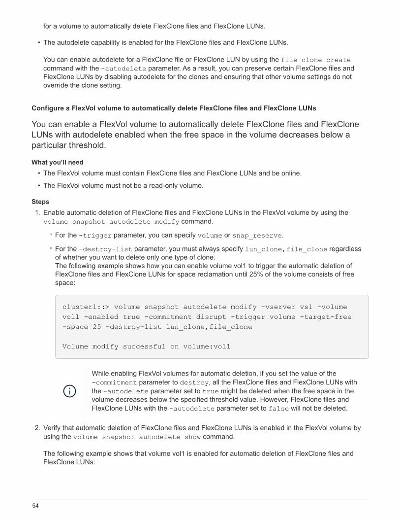
for a volume to automatically delete FlexClone files and FlexClone LUNs.
• The autodelete capability is enabled for the FlexClone files and FlexClone LUNs.
You can enable autodelete for a FlexClone file or FlexClone LUN by using the file clone create
command with the -autodelete parameter. As a result, you can preserve certain FlexClone files and
FlexClone LUNs by disabling autodelete for the clones and ensuring that other volume settings do not
override the clone setting.
Configure a FlexVol volume to automatically delete FlexClone files and FlexClone LUNs
You can enable a FlexVol volume to automatically delete FlexClone files and FlexClone
LUNs with autodelete enabled when the free space in the volume decreases below a
particular threshold.
What you’ll need
• The FlexVol volume must contain FlexClone files and FlexClone LUNs and be online.
• The FlexVol volume must not be a read-only volume.
Steps
1. Enable automatic deletion of FlexClone files and FlexClone LUNs in the FlexVol volume by using the
volume snapshot autodelete modify command.
◦ For the -trigger parameter, you can specify volume or snap_reserve.
◦ For the -destroy-list parameter, you must always specify lun_clone,file_clone regardless
of whether you want to delete only one type of clone.
The following example shows how you can enable volume vol1 to trigger the automatic deletion of
FlexClone files and FlexClone LUNs for space reclamation until 25% of the volume consists of free
space:
cluster1::> volume snapshot autodelete modify -vserver vs1 -volume
vol1 -enabled true -commitment disrupt -trigger volume -target-free
-space 25 -destroy-list lun_clone,file_clone
Volume modify successful on volume:vol1
While enabling FlexVol volumes for automatic deletion, if you set the value of the
-commitment parameter to destroy, all the FlexClone files and FlexClone LUNs with
the -autodelete parameter set to true might be deleted when the free space in the
volume decreases below the specified threshold value. However, FlexClone files and
FlexClone LUNs with the -autodelete parameter set to false will not be deleted.
2. Verify that automatic deletion of FlexClone files and FlexClone LUNs is enabled in the FlexVol volume by
using the volume snapshot autodelete show command.
The following example shows that volume vol1 is enabled for automatic deletion of FlexClone files and
FlexClone LUNs:
54
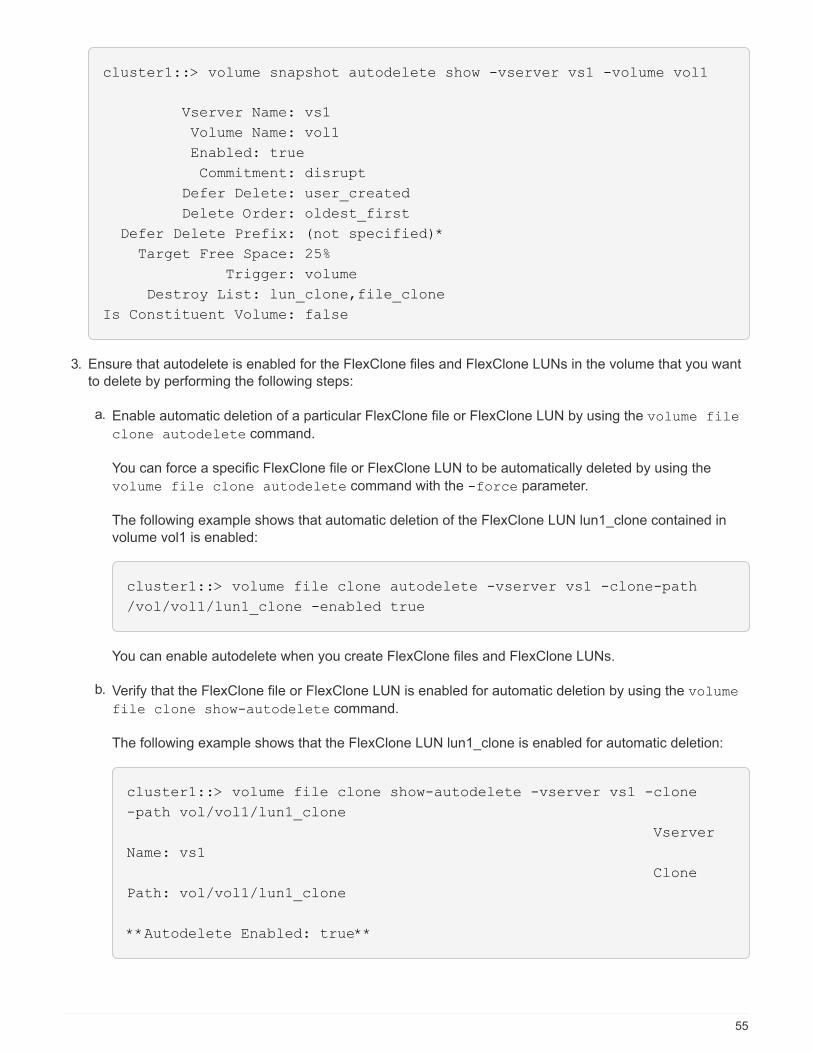
cluster1::> volume snapshot autodelete show -vserver vs1 -volume vol1
Vserver Name: vs1
Volume Name: vol1
Enabled: true
Commitment: disrupt
Defer Delete: user_created
Delete Order: oldest_first
Defer Delete Prefix: (not specified)*
Target Free Space: 25%
Trigger: volume
Destroy List: lun_clone,file_clone
Is Constituent Volume: false
3. Ensure that autodelete is enabled for the FlexClone files and FlexClone LUNs in the volume that you want
to delete by performing the following steps:
a. Enable automatic deletion of a particular FlexClone file or FlexClone LUN by using the volume file
clone autodelete command.
You can force a specific FlexClone file or FlexClone LUN to be automatically deleted by using the
volume file clone autodelete command with the -force parameter.
The following example shows that automatic deletion of the FlexClone LUN lun1_clone contained in
volume vol1 is enabled:
cluster1::> volume file clone autodelete -vserver vs1 -clone-path
/vol/vol1/lun1_clone -enabled true
You can enable autodelete when you create FlexClone files and FlexClone LUNs.
b. Verify that the FlexClone file or FlexClone LUN is enabled for automatic deletion by using the volume
file clone show-autodelete command.
The following example shows that the FlexClone LUN lun1_clone is enabled for automatic deletion:
cluster1::> volume file clone show-autodelete -vserver vs1 -clone
-path vol/vol1/lun1_clone
Vserver
Name: vs1
Clone
Path: vol/vol1/lun1_clone
**Autodelete Enabled: true**
55

For more information about using the commands, see the respective man pages.
Clone LUNs from an active volume
You can create copies of your LUNs by cloning the LUNs in the active volume. These
FlexClone LUNs are readable and writeable copies of the original LUNs in the active
volume.
What you’ll need
A FlexClone license must be installed.
About this task
A space-reserved FlexClone LUN requires as much space as the space-reserved parent LUN. If the FlexClone
LUN is not space-reserved, you must ensure that the volume has enough space to accommodate changes to
the FlexClone LUN.
Steps
1. You must have verified that the LUNs are not mapped to an igroup or are written to before making the
clone.
2. Use the lun show command to verify that the LUN exists.
lun show -vserver vs1
Vserver Path State Mapped Type Size
-------- ----------------- --------- --------- -------- -------
vs1 /vol/vol1/lun1 online unmapped windows 47.07MB
3. Use the volume file clone create command to create the FlexClone LUN.
volume file clone create -vserver vs1 -volume vol1 -source-path lun1
-destination-path/lun1_clone
If you need the FlexClone LUN to be available for automatic deletion, you include -autodelete true. If
you are creating this FlexClone LUN in a volume using semi-thick provisioning, you must enable automatic
deletion for all FlexClone LUNs.
4. Use the lun show command to verify that you created a LUN.
lun show -vserver vs1
Vserver Path State Mapped Type Size
-------- ----------------------- -------- -------- -------- ------
vs1 /vol/volX/lun1 online unmapped windows 47.07MB
vs1 /vol/volX/lun1_clone online unmapped windows 47.07MB
56

Create FlexClone LUNs from a Snapshot copy in a volume
You can use a Snapshot copy in your volume to create FlexClone copies of your LUNs.
FlexClone copies of LUNs are both readable and writeable.
What you’ll need
A FlexClone license must be installed.
About this task
The FlexClone LUN inherits the space reservations attribute of the parent LUN. A space-reserved FlexClone
LUN requires as much space as the space-reserved parent LUN. If the FlexClone LUN is not space-reserved,
the volume must have enough space to accommodate changes to the clone.
Steps
1. Verify that the LUN is not mapped or being written to.
2. Create a Snapshot copy of the volume that contains the LUNs:
volume snapshot create -vserver vserver_name -volume volume_name -snapshot
snapshot_name
You must create a Snapshot copy (the backing Snapshot copy) of the LUN you want to clone.
3. Create the FlexClone LUN from the Snapshot copy:
file clone create -vserver vserver_name -volume volume_name -source-path
source_path -snapshot-name snapshot_name -destination-path destination_path
If you need the FlexClone LUN to be available for automatic deletion, you include -autodelete true. If
you are creating this FlexClone LUN in a volume using semi-thick provisioning, you must enable automatic
deletion for all FlexClone LUNs.
4. Verify that the FlexClone LUN is correct:
lun show -vserver vserver_name
Vserver Path State Mapped Type Size
------- ---------------------- -------- --------- -------- -------
vs1 /vol/vol1/lun1_clone online unmapped windows 47.07MB
vs1 /vol/vol1/lun1_snap_clone online unmapped windows 47.07MB
Prevent a specific FlexClone file or FlexClone LUN from being automatically deleted
If you configure a FlexVol volume to automatically delete FlexClone files and FlexClone
LUNs, any clone that fits the criteria you specify might be deleted. If you have specific
FlexClone files or FlexClone LUNs that you want to preserve, you can exclude them from
the automatic FlexClone deletion process.
What you’ll need
A FlexClone license must be installed.
57

About this task
When you create a FlexClone file or FlexClone LUN, by default the autodelete setting for the clone is disabled.
FlexClone files and FlexClone LUNs with autodelete disabled are preserved when you configure a FlexVol
volume to automatically delete clones to reclaim space on the volume.
If you set the commitment level on the volume to try or disrupt, you can individually
preserve specific FlexClone files or FlexClone LUNs by disabling autodelete for those clones.
However, if you set the commitment level on the volume to destroy and the destroy lists
include lun_clone,file_clone, the volume setting overrides the clone setting, and all
FlexClone files and FlexClone LUNs can be deleted regardless of the autodelete setting for the
clones.
Steps
1. Prevent a specific FlexClone file or FlexClone LUN from being automatically deleted by using the volume
file clone autodelete command.
The following example shows how you can disable autodelete for FlexClone LUN lun1_clone contained in
vol1:
cluster1::> volume file clone autodelete -vserver vs1 -volume vol1
-clone-path lun1_clone -enable false
A FlexClone file or FlexClone LUN with autodelete disabled cannot be deleted automatically to reclaim
space on the volume.
2. Verify that autodelete is disabled for the FlexClone file or FlexClone LUN by using the volume file
clone show-autodelete command.
The following example shows that autodelete is false for the FlexClone LUN lun1_clone:
cluster1::> volume file clone show-autodelete -vserver vs1 -clone-path
vol/vol1/lun1_clone
Vserver
Name: vs1
Clone Path:
vol/vol1/lun1_clone
Autodelete
Enabled: false
Configure and use SnapVault backups in a SAN environment
Configure and use SnapVault backups in a SAN environment overview
SnapVault configuration and use in a SAN environment is very similar to configuration
and use in a NAS environment, but restoring LUNs in a SAN environment requires some
special procedures.
58

SnapVault backups contain a set of read-only copies of a source volume. In a SAN environment you always
back up entire volumes to the SnapVault secondary volume, not individual LUNs.
The procedure for creating and initializing the SnapVault relationship between a primary volume containing
LUNs and a secondary volume acting as a SnapVault backup is identical to the procedure used with FlexVol
volumes used for file protocols. This procedure is described in detail in Data Protection.
Data protection
It is important to ensure that LUNs being backed up are in a consistent state before the Snapshot copies are
created and copied to the SnapVault secondary volume. Automating the Snapshot copy creation with a product
like SnapManager for Microsoft SQL Server ensures that backed up LUNs are complete and usable by the
original application.
There are three basic choices for restoring LUNs from a SnapVault secondary volume:
• You can map a LUN directly from the SnapVault secondary volume and connect a host to the LUN to
access the contents of the LUN.
The LUN is read-only and you can map only from the most recent Snapshot copy in the SnapVault backup.
Persistent reservations and other LUN metadata are lost. If desired, you can use a copy program on the
host to copy the LUN contents back to the original LUN if it is still accessible.
The LUN has a different serial number from the source LUN.
• You can clone any Snapshot copy in the SnapVault secondary volume to a new read-write volume.
You can then map any of the LUNs in the volume and connect a host to the LUN to access the contents of
the LUN. If desired, you can use a copy program on the host to copy the LUN contents back to the original
LUN if it is still accessible.
• You can restore the entire volume containing the LUN from any Snapshot copy in the SnapVault secondary
volume.
Restoring the entire volume replaces all of the LUNs, and any files, in the volume. Any new LUNs created
since the Snapshot copy was created are lost.
The LUNs retain their mapping, serial numbers, UUIDs, and persistent reservations.
Access a read-only LUN copy from a SnapVault backup
You can access a read-only copy of a LUN from the latest Snapshot copy in a SnapVault
backup. The LUN ID, path, and serial number are different from the source LUN and must
first be mapped. Persistent reservations, LUN mappings, and igroups are not replicated
to the SnapVault secondary volume.
What you’ll need
• The SnapVault relationship must be initialized and the latest Snapshot copy in the SnapVault secondary
volume must contain the desired LUN.
• The storage virtual machine (SVM) containing the SnapVault backup must have one or more LIFs with the
desired SAN protocol accessible from the host used to access the LUN copy.
• If you plan to access LUN copies directly from the SnapVault secondary volume, you must create your
igroups on the SnapVault SVM in advance.
59

You can access a LUN directly from the SnapVault secondary volume without having to first restore or
clone the volume containing the LUN.
About this task
If a new Snapshot copy is added to the SnapVault secondary volume while you have a LUN mapped from a
previous Snapshot copy, the contents of the mapped LUN changes. The LUN is still mapped with the same
identifiers, but the data is taken from the new Snapshot copy. If the LUN size changes, some hosts
automatically detect the size change; Windows hosts require a disk rescan to pick up any size change.
Steps
1. Run the lun show command to list the available LUNs in the SnapVault secondary volume.
In this example, you can see both the original LUNs in the primary volume srcvolA and the copies in the
SnapVault secondary volume dstvolB:
cluster::> lun show
Vserver Path State Mapped Type Size
-------- ------------------ ------ ------- -------- -------
vserverA /vol/srcvolA/lun_A online mapped windows 300.0GB
vserverA /vol/srcvolA/lun_B online mapped windows 300.0GB
vserverA /vol/srcvolA/lun_C online mapped windows 300.0GB
vserverB /vol/dstvolB/lun_A online unmapped windows 300.0GB
vserverB /vol/dstvolB/lun_B online unmapped windows 300.0GB
vserverB /vol/dstvolB/lun_C online unmapped windows 300.0GB
6 entries were displayed.
2. If the igroup for the desired host does not already exist on the SVM containing the SnapVault secondary
volume, run the igroup create command to create an igroup.
This command creates an igroup for a Windows host that uses the iSCSI protocol:
cluster::> igroup create -vserver vserverB -igroup temp_igroup
-protocol iscsi -ostype windows
-initiator iqn.1991-05.com.microsoft:hostA
3. Run the lun mapping create command to map the desired LUN copy to the igroup.
cluster::> lun mapping create -vserver vserverB -path /vol/dstvolB/lun_A
-igroup temp_igroup
4. Connect the host to the LUN and access the contents of the LUN as desired.
60

Restore a single LUN from a SnapVault backup
You can restore a single LUN to a new location or to the original location. You can restore
from any Snapshot copy in the SnapVault secondary volume. To restore the LUN to the
original location, you first restore it to a new location and then copy it.
What you’ll need
• The SnapVault relationship must be initialized and the SnapVault secondary volume must contain an
appropriate Snapshot copy to restore.
• The storage virtual machine (SVM) containing the SnapVault secondary volume must have one or more
LIFs with the desired SAN protocol that are accessible from the host used to access the LUN copy.
• The igroups must already exist on the SnapVault SVM.
About this task
The process includes creating a read-write volume clone from a Snapshot copy in the SnapVault secondary
volume. You can use the LUN directly from the clone, or you can optionally copy the LUN contents back to the
original LUN location.
The LUN in the clone has a different path and serial number from the original LUN. Persistent reservations are
not retained.
Steps
1. Run the snapmirror show command to verify the secondary volume that contains the SnapVault
backup.
cluster::> snapmirror show
Source Dest Mirror Relation Total Last
Path Type Path State Status Progress Healthy Updated
-------- ---- --------- ------- --------- --------- ------- -------
vserverA:srcvolA
XDP vserverB:dstvolB
Snapmirrored
Idle - true -
2. Run the volume snapshot show command to identify the Snapshot copy that you want to restore the
LUN from.
61

cluster::> volume snapshot show
Vserver Volume Snapshot State Size Total% Used%
-------- ------- ---------------------- ----- ------ ------ -----
vserverB
dstvolB
snap2.2013-02-10_0010 valid 124KB 0% 0%
snap1.2013-02-10_0015 valid 112KB 0% 0%
snap2.2013-02-11_0010 valid 164KB 0% 0%
3. Run the volume clone create command to create a read-write clone from the desired Snapshot copy.
The volume clone is created in the same aggregate as the SnapVault backup. There must be enough
space in the aggregate to store the clone.
cluster::> volume clone create -vserver vserverB
-flexclone dstvolB_clone -type RW -parent-volume dstvolB
-parent-snapshot daily.2013-02-10_0010
[Job 108] Job succeeded: Successful
4. Run the lun show command to list the LUNs in the volume clone.
cluster::> lun show -vserver vserverB -volume dstvolB_clone
Vserver Path State Mapped Type
--------- ------------------------ ------- -------- --------
vserverB /vol/dstvolB_clone/lun_A online unmapped windows
vserverB /vol/dstvolB_clone/lun_B online unmapped windows
vserverB /vol/dstvolB_clone/lun_C online unmapped windows
3 entries were displayed.
5. If the igroup for the desired host does not already exist on the SVM containing the SnapVault backup, run
the igroup create command to create an igroup.
This example creates an igroup for a Windows host that uses the iSCSI protocol:
cluster::> igroup create -vserver vserverB -igroup temp_igroup
-protocol iscsi -ostype windows
-initiator iqn.1991-05.com.microsoft:hostA
6. Run the lun mapping create command to map the desired LUN copy to the igroup.
62

cluster::> lun mapping create -vserver vserverB
-path /vol/dstvolB_clone/lun_C -igroup temp_igroup
7. Connect the host to the LUN and access the contents of the LUN, as desired.
The LUN is read-write and can be used in place of the original LUN. Because the LUN serial number is
different, the host interprets it as a different LUN from the original.
8. Use a copy program on the host to copy the LUN contents back to the original LUN.
Restore all LUNs in a volume from a SnapVault backup
If one or more LUNs in a volume need to be restored from a SnapVault backup, you can
restore the entire volume. Restoring the volume affects all LUNs in the volume.
What you’ll need
The SnapVault relationship must be initialized and the SnapVault secondary volume must contain an
appropriate Snapshot copy to restore.
About this task
Restoring an entire volume returns the volume to the state it was in when the Snapshot copy was made. If a
LUN was added to the volume after the Snapshot copy, that LUN is removed during the restore process.
After restoring the volume, the LUNs remain mapped to the igroups they were mapped to just before the
restore. The LUN mapping might be different from the mapping at the time of the Snapshot copy. Persistent
reservations on the LUNs from host clusters are retained.
Steps
1. Stop I/O to all LUNs in the volume.
2. Run the snapmirror show command to verify the secondary volume that contains the SnapVault
secondary volume.
cluster::> snapmirror show
Source Dest Mirror Relation Total Last
Path Type Path State Status Progress Healthy Updated
-------- ---- --------- ------- --------- --------- ------- -------
vserverA:srcvolA
XDP vserverB:dstvolB
Snapmirrored
Idle - true -
3. Run the volume snapshot show command to identify the Snapshot copy that you want to restore from.
63

cluster::> volume snapshot show
Vserver Volume Snapshot State Size Total% Used%
-------- ------- ---------------------- ----- ------ ------ -----
vserverB
dstvolB
snap2.2013-02-10_0010 valid 124KB 0% 0%
snap1.2013-02-10_0015 valid 112KB 0% 0%
snap2.2013-02-11_0010 valid 164KB 0% 0%
4. Run the snapmirror restore command and specify the -source-snapshot option to specify the
Snapshot copy to use.
The destination you specify for the restore is the original volume you are restoring to.
cluster::> snapmirror restore -destination-path vserverA:srcvolA
-source-path vserverB:dstvolB -source-snapshot daily.2013-02-10_0010
Warning: All data newer than Snapshot copy hourly.2013-02-11_1205 on
volume vserverA:src_volA will be deleted.
Do you want to continue? {y|n}: y
[Job 98] Job is queued: snapmirror restore from source
"vserverB:dstvolB" for the snapshot daily.2013-02-10_0010.
5. If you are sharing LUNs across a host cluster, restore the persistent reservations on the LUNs from the
affected hosts.
Restoring a volume from a SnapVault backup
In the following example, the LUN named lun_D was added to the volume after the Snapshot copy was
created. After restoring the entire volume from the Snapshot copy, lun_D no longer appears.
In the lun show command output, you can see the LUNs in the primary volume srcvolA and the read-only
copies of those LUNs in the SnapVault secondary volume dstvolB. There is no copy of lun_D in the SnapVault
backup.
64

cluster::> lun show
Vserver Path State Mapped Type Size
--------- ------------------ ------- -------- -------- -------
vserverA /vol/srcvolA/lun_A online mapped windows 300.0GB
vserverA /vol/srcvolA/lun_B online mapped windows 300.0GB
vserverA /vol/srcvolA/lun_C online mapped windows 300.0GB
vserverA /vol/srcvolA/lun_D online mapped windows 250.0GB
vserverB /vol/dstvolB/lun_A online unmapped windows 300.0GB
vserverB /vol/dstvolB/lun_B online unmapped windows 300.0GB
vserverB /vol/dstvolB/lun_C online unmapped windows 300.0GB
7 entries were displayed.
cluster::>snapmirror restore -destination-path vserverA:srcvolA
-source-path vserverB:dstvolB
-source-snapshot daily.2013-02-10_0010
Warning: All data newer than Snapshot copy hourly.2013-02-11_1205
on volume vserverA:src_volA will be deleted.
Do you want to continue? {y|n}: y
[Job 98] Job is queued: snapmirror restore from source
"vserverB:dstvolB" for the snapshot daily.2013-02-10_0010.
cluster::> lun show
Vserver Path State Mapped Type Size
--------- ------------------ ------- -------- -------- -------
vserverA /vol/srcvolA/lun_A online mapped windows 300.0GB
vserverA /vol/srcvolA/lun_B online mapped windows 300.0GB
vserverA /vol/srcvolA/lun_C online mapped windows 300.0GB
vserverB /vol/dstvolB/lun_A online unmapped windows 300.0GB
vserverB /vol/dstvolB/lun_B online unmapped windows 300.0GB
vserverB /vol/dstvolB/lun_C online unmapped windows 300.0GB
6 entries were displayed.
After the volume is restored from the SnapVault secondary volume, the source volume no longer contains
lun_D. You do not need to remap the LUNs in the source volume after the restore because they are still
mapped.
How you can connect a host backup system to the primary storage system
You can back up SAN systems to tape through a separate backup host to avoid
performance degradation on the application host.
It is imperative that you keep SAN and NAS data separated for backup purposes. The figure below shows the
recommended physical configuration for a host backup system to the primary storage system. You must
65

configure volumes as SAN-only. LUNs can be confined to a single volume or the LUNs can be spread across
multiple volumes or storage systems.
Volumes on a host can consist of a single LUN mapped from the storage system or multiple LUNs using a
volume manager, such as VxVM on HP-UX systems.
Back up a LUN through a host backup system
You can use a cloned LUN from a Snapshot copy as source data for the host backup
system.
What you’ll need
A production LUN must exist and be mapped to an igroup that includes the WWPN or initiator node name of
the application server. The LUN must also be formatted and accessible to the host
Steps
1. Save the contents of the host file system buffers to disk.
You can use the command provided by your host operating system, or you can use SnapDrive for Windows
or SnapDrive for UNIX. You can also opt to make this step part of your SAN backup pre-processing script.
2. Use the volume snapshot create command to create a Snapshot copy of the production LUN.
volume snapshot create -vserver vs0 -volume vol3 -snapshot vol3_snapshot
-comment "Single snapshot" -foreground false
66

3. Use the volume file clone create command to create a clone of the production LUN.
volume file clone create -vserver vs3 -volume vol3 -source-path lun1 -snapshot
-name snap_vol3 -destination-path lun1_backup
4. Use the lun igroup create command to create an igroup that includes the WWPN of the backup
server.
lun igroup create -vserver vs3 -igroup igroup3 -protocol fc -ostype windows
-initiator 10:00:00:00:c9:73:5b:91
5. Use the lun mapping create command to map the LUN clone you created in Step 3 to the backup
host.
lun mapping create -vserver vs3 -volume vol3 -lun lun1_backup -igroup igroup3
You can opt to make this step part of your SAN backup application’s post-processing script.
6. From the host, discover the new LUN and make the file system available to the host.
You can opt to make this step part of your SAN backup application’s post-processing script.
7. Back up the data in the LUN clone from the backup host to tape by using your SAN backup application.
8. Use the lun modify command to take the LUN clone offline.
lun modify -vserver vs3 -path /vol/vol3/lun1_backup -state offline
9. Use the lun delete to remove the LUN clone.
lun delete -vserver vs3 -volume vol3 -lun lun1_backup
10. Use the volume snapshot delete command to remove the Snapshot copy.
volume snapshot delete -vserver vs3 -volume vol3 -snapshot vol3_snapshot
Considerations for SAN configurations in a MetroClusterenvironment
You must be aware of certain considerations when using SAN configurations in a
MetroCluster environment.
• MetroCluster configurations do not support front-end FC fabric “routed” vSAN configurations.
• MetroCluster configurations do not support front-end NVMe host connectivity.
• Other SAN protocols are supported on MetroCluster configurations.
• When using SAN client configurations, you must check whether any special considerations for
MetroCluster configurations are included in the notes that are provided in the Interoperability Matrix Tool
(IMT).
• The MetroCluster is using the same WWPNs on both sides of the front-end SAN.
67

During switchover, the FC port on the surviving site might log in to the fabric before the fabric
has detected that the FC port on the disaster site is offline and has removed this port from the
name and directory services. If the FC port on the disaster is not yet removed, the fabric login
attempt of the FC port at the surviving site might be rejected due to a duplicate WWPN. This
behavior of the FC switches can be changed to honor the login of the previous device and not
the existing one. You should verify the effects of this behavior on other fabric devices. Contact
the switch vendor for more information.
Steps
To avoid overlap when the old port goes offline and the new port comes online, use the following steps to
configure the front-end switches:
For a… Use these steps:
Cisco switch 1. Connect to the switch and log in.
2. Enter configuration mode:
switch# config t
switch(config)#
3. Overwrite the first device entry in the name server database with the new device:
switch(config)# no fcns reject-duplicate-pwwn vsan 1
4. In switches that are running NX-OS 8.x, confirm that the flogi quiesce timeout is set
to zero:
a. Display the quiesce timerval:
switch(config)# show flogi interval info | i quiesce
Stats: fs flogi quiesce timerval: 0
b. If the output in the previous step does not indicate that the timerval is zero, then
set it to zero:
switch(config)# flogi scale enable
switch(config)$ flogi quiesce timeout 0
68

Brocade switch 1. Connect to the switch and log in.
2. Enter the switchDisable command.
3. Enter the configure command, and press y at the prompt.
F-Port login parameters (yes, y, no, n): [no] y
4. Choose setting 1:
- 0: First login take precedence over the second login
(default)
- 1: Second login overrides first login.
- 2: the port type determines the behavior
Enforce FLOGI/FDISC login: (0..2) [0] 1
5. Respond to the remaining prompts, or press Ctrl + D.
6. Enter the switchEnable command.
For further MetroCluster-specific host information, refer to the following NetApp Knowledgebase articles:
What are AIX Host support considerations in a MetroCluster configuration?
Solaris host support considerations in a MetroCluster configuration
Related information
NetApp Interoperability Matrix Tool
SAN Concepts
About SAN host provisioning
SAN provisioning with iSCSI
In SAN environments, storage systems are targets that have storage target devices. For
iSCSI and FC, the storage target devices are referred to as LUNs (logical units). For Non-
Volatile Memory Express (NVMe) over Fibre Channel, the storage target devices are
referred to as namespaces.
You configure storage by creating LUNs for iSCSI and FC or by creating namespaces for NVMe. The LUNs or
namespaces are then accessed by hosts using Internet Small Computer Systems Interface (iSCSI) or Fibre
Channel (FC) protocol networks.
To connect to iSCSI networks, hosts can use standard Ethernet network adapters (NICs), TCP offload engine
(TOE) cards with software initiators, converged network adapters (CNAs), or dedicated iSCSI host bus
adapters (HBAs).
69

To connect to FC networks, hosts require FC HBAs or CNAs.
Supported FC protocols include:
• FC
• FCoE
• NVMe
iSCSI target node network connections and names
iSCSI target nodes can connect to the network in several ways:
• Over Ethernet interfaces using software that is integrated into ONTAP.
• Over multiple system interfaces, with an interface used for iSCSI that can also transmit traffic for other
protocols, such as SMB and NFS.
• Using a unified target adapter (UTA) or a converged network adapter (CNA).
Every iSCSI node must have a node name.
The two formats, or type designators, for iSCSI node names are iqn and eui. The SVM iSCSI target always
uses the iqn-type designator. The initiator can use either the iqn-type or eui-type designator.
Storage system node name
Each SVM running iSCSI has a default node name based on a reverse domain name and a unique encoding
number.
The node name is displayed in the following format:
iqn.1992-08.com.netapp:sn.unique-encoding-number
The following example shows the default node name for a storage system with a unique encoding number:
iqn.1992-08.com.netapp:sn.812921059e6c11e097b3123478563412:vs.6
TCP port for iSCSI
The iSCSI protocol is configured in ONTAP to use TCP port number 3260.
ONTAP does not support changing the port number for iSCSI. Port number 3260 is registered as part of the
iSCSI specification and cannot be used by any other application or service.
Related information
NetApp Documentation: ONTAP SAN Host Configuration
iSCSI service management
iSCSI service management
You can manage the availability of the iSCSI service on the iSCSI logical interfaces of the
storage virtual machine (SVM) by using the vserver iscsi interface enable or
vserver iscsi interface disable commands.
70

By default, the iSCSI service is enabled on all iSCSI logical interfaces.
How iSCSI is implemented on the host
iSCSI can be implemented on the host using hardware or software.
You can implement iSCSI in one of the following ways:
• Using Initiator software that uses the host’s standard Ethernet interfaces.
• Through an iSCSI host bus adapter (HBA): An iSCSI HBA appears to the host operating system as a SCSI
disk adapter with local disks.
• Using a TCP Offload Engine (TOE) adapter that offloads TCP/IP processing.
The iSCSI protocol processing is still performed by host software.
How iSCSI authentication works
During the initial stage of an iSCSI session, the initiator sends a login request to the
storage system to begin an iSCSI session. The storage system then either permits or
denies the login request, or determine that a login is not required.
iSCSI authentication methods are:
• Challenge Handshake Authentication Protocol (CHAP)--The initiator logs in using a CHAP user name and
password.
You can specify a CHAP password or generate a hexadecimal secret password. There are two types of
CHAP user names and passwords:
◦ Inbound—The storage system authenticates the initiator.
Inbound settings are required if you are using CHAP authentication.
◦ Outbound—This is an optional setting to enable the initiator to authenticate the storage system.
You can use outbound settings only if you define an inbound user name and password on the storage
system.
• deny—The initiator is denied access to the storage system.
• none—The storage system does not require authentication for the initiator.
You can define the list of initiators and their authentication methods. You can also define a default
authentication method that applies to initiators that are not on this list.
Related information
Windows Multipathing Options with Data ONTAP: Fibre Channel and iSCSI
iSCSI initiator security management
ONTAP provides a number of features for managing security for iSCSI initiators. You can
define a list of iSCSI initiators and the authentication method for each, display the
initiators and their associated authentication methods in the authentication list, add and
71

remove initiators from the authentication list, and define the default iSCSI initiator
authentication method for initiators not in the list.
iSCSI endpoint isolation
Beginning with ONTAP 9.1 existing iSCSI security commands were enhanced to accept
an IP address range, or multiple IP addresses.
All iSCSI initiators must provide origination IP addresses when establishing a session or connection with a
target. This new functionality prevents an initiator from logging into the cluster if the origination IP address is
unsupported or unknown, providing a unique identification scheme. Any initiator originating from an
unsupported or unknown IP address will have their login rejected at the iSCSI session layer, preventing the
initiator from accessing any LUN or volume within the cluster.
Implement this new functionality with two new commands to help manage pre-existing entries.
Add initiator address range
Improve iSCSI initiator security management by adding an IP address range, or multiple IP addresses with the
vserver iscsi security add-initiator-address-range command.
cluster1::> vserver iscsi security add-initiator-address-range
Remove initiator address range
Remove an IP address range, or multiple IP addresses, with the vserver iscsi security remove-
initiator-address-range command.
cluster1::> vserver iscsi security remove-initiator-address-range
What CHAP authentication is
The Challenge Handshake Authentication Protocol (CHAP) enables authenticated
communication between iSCSI initiators and targets. When you use CHAP
authentication, you define CHAP user names and passwords on both the initiator and the
storage system.
During the initial stage of an iSCSI session, the initiator sends a login request to the storage system to begin
the session. The login request includes the initiator’s CHAP user name and CHAP algorithm. The storage
system responds with a CHAP challenge. The initiator provides a CHAP response. The storage system verifies
the response and authenticates the initiator. The CHAP password is used to compute the response.
Guidelines for using CHAP authentication
You should follow certain guidelines when using CHAP authentication.
• If you define an inbound user name and password on the storage system, you must use the same user
name and password for outbound CHAP settings on the initiator. If you also define an outbound user name
and password on the storage system to enable bidirectional authentication, you must use the same user
name and password for inbound CHAP settings on the initiator.
• You cannot use the same user name and password for inbound and outbound settings on the storage
system.
72

• CHAP user names can be 1 to 128 bytes.
A null user name is not allowed.
• CHAP passwords (secrets) can be 1 to 512 bytes.
Passwords can be hexadecimal values or strings. For hexadecimal values, you should enter the value with
a prefix of “0x” or “0X”. A null password is not allowed.
• For additional restrictions, you should see the initiator’s documentation.
For example, the Microsoft iSCSI software initiator requires both the initiator and target CHAP passwords
to be at least 12 bytes if IPsec encryption is not being used. The maximum password length is 16 bytes
regardless of whether IPsec is used.
How using iSCSI interface access lists to limit initiator interfaces can increase performance and security
ISCSI interface access lists can be used to limit the number of LIFs in an SVM that an
initiator can access, thereby increasing performance and security.
When an initiator begins a discovery session using an iSCSI SendTargets command, it receives the IP
addresses associated with the LIF (network interface) that is in the access list. By default, all initiators have
access to all iSCSI LIFs in the SVM. You can use the access list to restrict the number of LIFs in an SVM that
an initiator has access to.
iSNS server registration requirement
What iSNS is
The Internet Storage Name Service (iSNS) is a protocol that enables automated
discovery and management of iSCSI devices on a TCP/IP storage network. An iSNS
server maintains information about active iSCSI devices on the network, including their IP
addresses, iSCSI node names IQN’s, and portal groups.
You can obtain an iSNS server from a third-party vendor. If you have an iSNS server on your network
configured and enabled for use by the initiator and target, you can use the management LIF for a storage
virtual machine (SVM) to register all the iSCSI LIFs for that SVM on the iSNS server. After the registration is
complete, the iSCSI initiator can query the iSNS server to discover all the LIFs for that particular SVM.
If you decide to use an iSNS service, you must ensure that your storage virtual machines (SVMs) are properly
registered with an Internet Storage Name Service (iSNS) server.
If you do not have an iSNS server on your network, you must manually configure each target to be visible to
the host.
What an iSNS server does
An iSNS server uses the Internet Storage Name Service (iSNS) protocol to maintain information about active
iSCSI devices on the network, including their IP addresses, iSCSI node names (IQNs), and portal groups.
The iSNS protocol enables automated discovery and management of iSCSI devices on an IP storage network.
An iSCSI initiator can query the iSNS server to discover iSCSI target devices.
73

NetApp does not supply or resell iSNS servers. You can obtain these servers from a vendor supported by
NetApp.
How SVMs interact with an iSNS server
The iSNS server communicates with each storage virtual machine (SVM) through the
SVM management LIF. The management LIF registers all iSCSI target node name, alias,
and portal information with the iSNS service for a specific SVM.
In the following example, SVM VS1 uses the SVM management LIF vs1_mgmt_lif to register with the iSNS
server. During iSNS registration, an SVM sends all the iSCSI LIFs through the SVM management LIF to the
iSNS Server. After the iSNS registration is complete, the iSNS server has a list of all the LIFs serving iSCSI in
VS1. If a cluster contains multiple SVMs, each SVM must register individually with the iSNS server to use the
iSNS service.
In the next example, after the iSNS server completes the registration with the target, Host A can discover all
the LIFs for VS1 through the iSNS server as indicated in step 1. After Host A completes the discovery of the
LIFs for VS1, Host A can establish a connection with any of the LIFs in VS1 as shown in step 2. Host A is not
aware of any of the LIFs in VS2 until the management LIF VS2_mgmt_LIF for VS2 registers with the iSNS
server.
74

However, if you define the interface access lists, the host can only use the defined LIFs in the interface access
list to access the target.
After iSNS is initially configured, ONTAP automatically updates the iSNS server when the SVM configuration
settings change.
A delay of a few minutes can occur between the time you make the configuration changes and when ONTAP
sends the update to the iSNS server. Force an immediate update of the iSNS information on the iSNS server:
vserver iscsi isns update
Commands for managing iSNS
ONTAP provides commands to manage your iSNS service.
If you want to… Use this command…
Configure an iSNS service vserver iscsi isns create
Start an iSNS service vserver iscsi isns start
Modify an iSNS service vserver iscsi isns modify
Display iSNS service configuration vserver iscsi isns show
Force an update of registered iSNS information vserver iscsi isns update
75

If you want to… Use this command…
Stop an iSNS service vserver iscsi isns stop
Remove an iSNS service vserver iscsi isns delete
View the man page for a command man command name
See the man page for each command for more information.
SAN provisioning with FC
You should be aware of the important concepts that are required to understand how
ONTAP implements an FC SAN.
How FC target nodes connect to the network
Storage systems and hosts have adapters so that they can be connected to FC switches with cables.
When a node is connected to the FC SAN, each SVM registers the World Wide Port Name (WWPN) of its LIF
with the switch Fabric Name Service. The WWNN of the SVM and the WWPN of each LIF is automatically
assigned by ONTAP..
Direct-connection to nodes from hosts with FC is not supported, NPIV is required and this
requires a switch to be used.With iSCSI sessions, communication works with connections that
are either network routed or direct-connect. However, both of these methods are supported with
ONTAP.
How FC nodes are identified
Each SVM configured with FC is identified by a worldwide node name (WWNN).
How WWPNs are used
WWPNs identify each LIF in an SVM configured to support FC. These LIFs utilize the physical FC ports in each
node in the cluster, which can be FC target cards, UTA or UTA2 configured as FC or FCoE in the nodes.
• Creating an initiator group
The WWPNs of the host’s HBAs are used to create an initiator group (igroup). An igroup is used to control
host access to specific LUNs. You can create an igroup by specifying a collection of WWPNs of initiators in
an FC network. When you map a LUN on a storage system to an igroup, you can grant all the initiators in
that group access to that LUN. If a host’s WWPN is not in an igroup that is mapped to a LUN, that host
does not have access to the LUN. This means that the LUNs do not appear as disks on that host.
You can also create port sets to make a LUN visible only on specific target ports. A port set consists of a
group of FC target ports. You can bind an igroup to a port set. Any host in the igroup can access the LUNs
only by connecting to the target ports in the port set.
• Uniquely identifying FC LIFs
WWPNs uniquely identify each FC logical interface. The host operating system uses the combination of the
76

WWNN and WWPN to identify SVMs and FC LIFs. Some operating systems require persistent binding to
ensure that the LUN appears at the same target ID on the host.
How worldwide name assignments work
Worldwide names are created sequentially in ONTAP. However, because of the way ONTAP assigns them,
they might appear to be assigned in a non-sequential order.
Each adapter has a pre-configured WWPN and WWNN, but ONTAP does not use these pre-configured values.
Instead, ONTAP assigns its own WWPNs or WWNNs, based on the MAC addresses of the onboard Ethernet
ports.
The worldwide names might appear to be non-sequential when assigned for the following reasons:
• Worldwide names are assigned across all the nodes and storage virtual machines (SVMs) in the cluster.
• Freed worldwide names are recycled and added back to the pool of available names.
How FC switches are identified
Fibre Channel switches have one worldwide node name (WWNN) for the device itself, and one worldwide port
name (WWPN) for each of its ports.
For example, the following diagram shows how the WWPNs are assigned to each of the ports on a 16-port
Brocade switch. For details about how the ports are numbered for a particular switch, see the vendor-supplied
documentation for that switch.
Port 0, WWPN 20:00:00:60:69:51:06:b4
Port 1, WWPN 20:01:00:60:69:51:06:b4
Port 14, WWPN 20:0e:00:60:69:51:06:b4
Port 15, WWPN 20:0f:00:60:69:51:06:b4
SAN provisioning with NVMe
Beginning with ONTAP 9.4, NVMe/FC is supported in SAN environment. NVMe/FC
enables storage administrators to provision namespaces and subsystems and then map
the namespaces to subsystems, similar to the way LUNs are provisioned and mapped to
igroups for FC and iSCSI.
An NVMe namespace is a quantity of non-volatile memory that can be formatted into logical blocks.
Namespaces are the equivalent of LUNs for FC and iSCSI protocols, and an NVMe subsystem is analogous to
an igroup. An NVMe subsystem can be associated with initiators so that namespaces within the subsystem
can be accessed by the associated initiators.
77
Although analogous in function, NVMe namespaces do not support all features supported by
LUNs.
Beginning with ONTAP 9.5 a license is required to support host-facing data access with NVMe. If NVMe is
enabled in ONTAP 9.4, a 90 day grace period is given to acquire the license after upgrading to ONTAP 9.5.
You can enable the license using the following command:
system license add -license-code NVMe_license_key
Related information
NetApp Technical Report 4684: Implementing and Configuring Modern SANs with NVMe/FC
About SAN volumes
About SAN volumes overview
ONTAP provides three basic volume provisioning options: thick provisioning, thin
provisioning, and semi-thick provisioning. Each option uses different ways to manage the
volume space and the space requirements for ONTAP block sharing technologies.
Understanding how the options work enables you to choose the best option for your
environment.
Putting SAN LUNs and NAS shares in the same FlexVol volume is not recommended. You
should provision separate FlexVol volumes specifically for your SAN LUNs and you should
provision separate FlexVol volumes specifically to your NAS shares. This simplifies
management and replication deployments and parallels the way FlexVol volumes are supported
in Active IQ Unified Manager (formerly OnCommand Unified Manager).
Thin provisioning for volumes
When a thinly provisioned volume is created, ONTAP does not reserve any extra space when the volume is
created. As data is written to the volume, the volume requests the storage it needs from the aggregate to
accommodate the write operation. Using thin-provisioned volumes enables you to overcommit your aggregate,
which introduces the possibility of the volume not being able to secure the space it needs when the aggregate
runs out of free space.
You create a thin-provisioned FlexVol volume by setting its -space-guarantee option to none.
Thick provisioning for volumes
When a thick-provisioned volume is created, ONTAP sets aside enough storage from the aggregate to ensure
that any block in the volume can be written to at any time. When you configure a volume to use thick
provisioning, you can employ any of the ONTAP storage efficiency capabilities, such as compression and
deduplication, to offset the larger upfront storage requirements.
You create a thick-provisioned FlexVol volume by setting its -space-slo (service level objective) option to
thick.
Semi-thick provisioning for volumes
When a volume using semi-thick provisioning is created, ONTAP sets aside storage space from the aggregate
to account for the volume size. If the volume is running out of free space because blocks are in use by block-
78

sharing technologies, ONTAP makes an effort to delete protection data objects (Snapshot copies and
FlexClone files and LUNs) to free up the space they are holding. As long as ONTAP can delete the protection
data objects fast enough to keep pace with the space required for overwrites, the write operations continue to
succeed. This is called a “best effort” write guarantee.
You cannot employ storage efficiency technologies such as deduplication, compression, and
compaction on a volume that is using semi-thick provisioning.
You create a semi-thick-provisioned FlexVol volume by setting its -space-slo (service level objective) option
to semi-thick.
Use with space-reserved files and LUNs
A space-reserved file or LUN is one for which storage is allocated when it is created. Historically, NetApp has
used the term “thin-provisioned LUN” to mean a LUN for which space reservation is disabled (a non-space-
reserved LUN).
Non-space-reserved files are not generally referred to as “thin-provisioned files”.
The following table summarizes the major differences in how the three volume provisioning options can be
used with space-reserved files and LUNs:
Volume
provisioning
LUN/file space
reservation
Overwrites Protection data2 Storage efficiency3
Thick Supported Guaranteed1 Guaranteed Supported
Thin No effect None Guaranteed Supported
Semi-thick Supported Best effort1 Best effort Not supported
Notes
1. The ability to guarantee overwrites or provide a best-effort overwrite assurance requires that space
reservation is enabled on the LUN or file.
2. Protection data includes Snapshot copies, and FlexClone files and LUNs marked for automatic deletion
(backup clones).
3. Storage efficiency includes deduplication, compression, any FlexClone files and LUNs not marked for
automatic deletion (active clones), and FlexClone subfiles (used for Copy Offload).
Support for SCSI thin-provisioned LUNs
ONTAP supports T10 SCSI thin-provisioned LUNs as well as NetApp thin-provisioned LUNs. T10 SCSI thin
provisioning enables host applications to support SCSI features including LUN space reclamation and LUN
space monitoring capabilities for blocks environments. T10 SCSI thin provisioning must be supported by your
SCSI host software.
You use the ONTAP space-allocation setting to enable/disable support for the T10 thin provisioning on a
LUN. You use the ONTAP space-allocation enable setting to enable T10 SCSI thin provisioning on a
LUN.
79

The [-space-allocation {enabled|disabled}] command in the ONTAP Command Reference
Manual has more information to enable/disable support for the T10 thin provisioning and to enable T10 SCSI
thin provisioning on a LUN.
ONTAP 9 commands
Configure volume provisioning options
You can configure a volume for thin provisioning, thick provisioning, or semi-thick
provisioning.
About this task
Setting the -space-slo option to thick ensures the following:
• The entire volume is preallocated in the aggregate. You cannot use the volume create or volume
modify command to configure the volume’s -space-guarantee option.
• 100% of the space required for overwrites is reserved. You cannot use the volume modify command to
configure the volume’s -fractional-reserve option
Setting the -space-slo option to semi-thick ensures the following:
• The entire volume is preallocated in the aggregate. You cannot use the volume create or volume
modify command to configure the volume’s -space-guarantee option.
• No space is reserved for overwrites. You can use the volume modify command to configure the
volume’s -fractional-reserve option.
• Automatic deletion of Snapshot copies is enabled.
Step
1. Configure volume provisioning options:
volume create -vserver vserver_name -volume volume_name -aggregate
aggregate_name -space-slo none|thick|semi-thick -space-guarantee none|volume
The -space-guarantee option defaults to none for AFF systems and for non-AFF DP volumes.
Otherwise, it defaults to volume. For existing FlexVol volumes, use the volume modify command to
configure provisioning options.
The following command configures vol1 on SVM vs1 for thin provisioning:
cluster1::> volume create –vserver vs1 -volume vol1 -space-guarantee
none
The following command configures vol1 on SVM vs1 for thick provisioning:
cluster1::> volume create –vserver vs1 -volume vol1 -space-slo thick
The following command configures vol1 on SVM vs1 for semi-thick provisioning:
80

cluster1::> volume create –vserver vs1 -volume vol1 -space-slo semi-
thick
SAN volume configuration options
You must set various options on the volume containing your LUN. The way you set the
volume options determines the amount of space available to LUNs in the volume.
Autogrow
You can enable or disable Autogrow. If you enable it, autogrow allows ONTAP to automatically increase the
size of the volume up to a maximum size that you predetermine. There must be space available in the
containing aggregate to support the automatic growth of the volume. Therefore, if you enable autogrow, you
must monitor the free space in the containing aggregate and add more when needed.
Autogrow cannot be triggered to support Snapshot creation. If you attempt to create a Snapshot copy and
there is insufficient space on the volume, the Snapshot creation fails, even with autogrow enabled.
If autogrow is disabled, the size of your volume will remain the same.
Autoshrink
You can enable or disable Autoshrink. If you enable it, autoshrink allows ONTAP to automatically decrease the
overall size of a volume when the amount of space consumed in the volume decreases a predetermined
threshold. This increases storage efficiency by triggering volumes to automatically release unused free space.
Snapshot autodelete
Snapshot autodelete automatically deletes Snapshot copies when one of the following occurs:
• The volume is nearly full.
• The Snapshot reserve space is nearly full.
• The overwrite reserve space is full.
You can configure Snapshot autodelete to delete Snapshot copies from oldest to newest or from newest to
oldest. Snapshot autodelete does not delete Snapshot copies that are linked to Snapshot copies in cloned
volumes or LUNs.
If your volume needs additional space and you have enabled both autogrow and Snapshot autodelete, by
default, ONTAP attempts to acquire the needed space by triggering autogrow first. If enough space is not
acquired through autogrow, then Snapshot autodelete is triggered.
Snapshot reserve
Snapshot reserve defines the amount of space in the volume reserved for Snapshot copies. Space allocated to
Snapshot reserve cannot be used for any other purpose. If all of the space allocated for Snapshot reserve is
used, then Snapshot copies begin to consume additional space on the volume.
Requirement for moving volumes in SAN environments
Before you move a volume that contains LUNs or namespaces, you must meet certain
81

requirements.
• For volumes containing one or more LUNs, you should have a minimum of two paths per LUN (LIFs)
connecting to each node in the cluster.
This eliminates single points of failure and enables the system to survive component failures.
• For volumes containing namespaces, the cluster must be running ONTAP 9.6 or later.
Volume move is not supported for NVMe configurations running ONTAP 9.5.
Considerations for setting fractional reserve
Fractional reserve, also called LUN overwrite reserve, enables you to turn off overwrite
reserve for space-reserved LUNs and files in a FlexVol volume. This can help you
maximize your storage utilization, but if your environment is negatively affected by write
operations failing due to lack of space, you must understand the requirements that this
configuration imposes.
The fractional reserve setting is expressed as a percentage; the only valid values are 0 and 100 percent. The
fractional reserve setting is an attribute of the volume.
Setting fractional reserve to 0 increases your storage utilization. However, an application accessing data
residing in the volume could experience a data outage if the volume is out of free space, even with the volume
guarantee set to volume. With proper volume configuration and use, however, you can minimize the chance of
writes failing. ONTAP provides a “best effort” write guarantee for volumes with fractional reserve set to 0 when
all of the following requirements are met:
• Deduplication is not in use
• Compression is not in use
• FlexClone sub-files are not in use
• All FlexClone files and FlexClone LUNs are enabled for automatic deletion
This is not the default setting. You must explicitly enable automatic deletion, either at creation time or by
modifying the FlexClone file or FlexClone LUN after it is created.
• ODX and FlexClone copy offload are not in use
• Volume guarantee is set to volume
• File or LUN space reservation is enabled
• Volume Snapshot reserve is set to 0
• Volume Snapshot copy automatic deletion is enabled with a commitment level of destroy, a destroy list
of lun_clone,vol_clone,cifs_share,file_clone,sfsr, and a trigger of volume
This setting also ensures that FlexClone files and FlexClone LUNs are deleted when necessary.
Note that if your rate of change is high, in rare cases the Snapshot copy automatic deletion could fall behind,
resulting in the volume running out of space, even with all of the above required configuration settings in use.
In addition, you can optionally use the volume autogrow capability to decrease the likelihood of volume
82
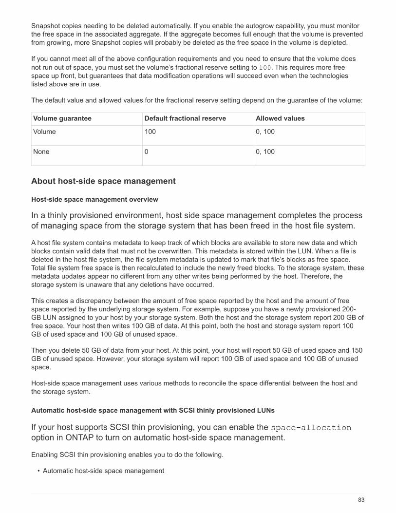
Snapshot copies needing to be deleted automatically. If you enable the autogrow capability, you must monitor
the free space in the associated aggregate. If the aggregate becomes full enough that the volume is prevented
from growing, more Snapshot copies will probably be deleted as the free space in the volume is depleted.
If you cannot meet all of the above configuration requirements and you need to ensure that the volume does
not run out of space, you must set the volume’s fractional reserve setting to 100. This requires more free
space up front, but guarantees that data modification operations will succeed even when the technologies
listed above are in use.
The default value and allowed values for the fractional reserve setting depend on the guarantee of the volume:
Volume guarantee Default fractional reserve Allowed values
Volume 100 0, 100
None 0 0, 100
About host-side space management
Host-side space management overview
In a thinly provisioned environment, host side space management completes the process
of managing space from the storage system that has been freed in the host file system.
A host file system contains metadata to keep track of which blocks are available to store new data and which
blocks contain valid data that must not be overwritten. This metadata is stored within the LUN. When a file is
deleted in the host file system, the file system metadata is updated to mark that file’s blocks as free space.
Total file system free space is then recalculated to include the newly freed blocks. To the storage system, these
metadata updates appear no different from any other writes being performed by the host. Therefore, the
storage system is unaware that any deletions have occurred.
This creates a discrepancy between the amount of free space reported by the host and the amount of free
space reported by the underlying storage system. For example, suppose you have a newly provisioned 200-
GB LUN assigned to your host by your storage system. Both the host and the storage system report 200 GB of
free space. Your host then writes 100 GB of data. At this point, both the host and storage system report 100
GB of used space and 100 GB of unused space.
Then you delete 50 GB of data from your host. At this point, your host will report 50 GB of used space and 150
GB of unused space. However, your storage system will report 100 GB of used space and 100 GB of unused
space.
Host-side space management uses various methods to reconcile the space differential between the host and
the storage system.
Automatic host-side space management with SCSI thinly provisioned LUNs
If your host supports SCSI thin provisioning, you can enable the space-allocation
option in ONTAP to turn on automatic host-side space management.
Enabling SCSI thin provisioning enables you to do the following.
• Automatic host-side space management
83

When data is deleted on a host that supports SCSI thin provisioning, host-side space management
identifies the blocks of deleted data on the host file system and automatically issues one or more SCSI
UNMAP commands to free corresponding blocks on the storage system.
• Notify the host when a LUN runs out of space while keeping the LUN online
On hosts that do not support SCSI thin provisioning, when the volume containing LUN runs out of space
and cannot automatically grow, ONTAP takes the LUN offline. However, on hosts that support SCSI thin
provisioning, ONTAP does not take the LUN offline when it runs out of space. The LUN remains online in
read-only mode and the host is notified that the LUN can no longer accept writes.
Related information
ONTAP SAN host configuration
Enable space allocation for SCSI thinly provisioned LUNs
If you set the space-allocation option to enabled, ONTAP notifies the host when
the volume has run out of space and the LUN in the volume cannot accept writes. This
option also enables ONTAP to reclaim space automatically when your host deletes data.
About this task
The space-allocation option is set to disabled by default, and you must take the LUN offline to enable
space allocation. After you enable space allocation, you must perform discovery on the host before the host
will recognize that space allocation has been enabled.
Steps
1. Set the -space-allocation parameter to enabled:
lun modify -vserver vserver_name -volume volume_name -lun lun_name -space
-allocation enabled
2. Verify that space allocation is enabled:
lun show -vserver vserver_name -volume volume_name -lun lun_name -fields
space-allocation
3. Bring the LUN online:
lun modify -vserver vserver_name -volume volume_name -lun lun_name -state
online
4. On the host, rescan all disks to ensure that the change to the -space-allocation option is correctly
discovered.
Host support for SCSI thin provisioning
To leverage the benefits of SCSI thin provisioning, it must be supported by your host.
SCSI thin provisioning uses the Logical Block Provisioning feature as defined in the SCSI
SBC-3 standard. Only hosts that support this standard can use SCSI thin provisioning in
ONTAP.
84

The following hosts currently support SCSI thin provisioning when you enable space allocation:
• VMware ESX 5.0 and later
• Red Hat Enterprise Linux 6.2 and later
• Citrix XenServer 6.5 and later
• Microsoft Windows 2012
• Microsoft Windows 2016
When you enable the space allocation functionality in ONTAP, you turn on the following SCSI thin provisioning
features:
• Unmapping and reporting space usage for space reclamation
• Reporting resource exhaustion errors
Simplified host management with SnapCenter
You can use SnapCenter software to simplify some of the management and data
protection tasks associated with iSCSI and FC storage. SnapCenter is an optional
management package for Windows and UNIX hosts.
You can use SnapCenter Software to easily create virtual disks from pools of storage that can be distributed
among several storage systems and to automate storage provisioning tasks and simplify the process of
creating Snapshot copies and clones from Snapshot copies consistent with host data.
See NetApp product documentation for more information on SnapCenter.
About igroups
Initiator groups (igroups) are tables of FC protocol host WWPNs or iSCSI host node
names. You can define igroups and map them to LUNs to control which initiators have
access to LUNs.
Typically, you want all of the host’s initiator ports or software initiators to have access to a LUN. If you are using
multipathing software or have clustered hosts, each initiator port or software initiator of each clustered host
needs redundant paths to the same LUN.
You can create igroups that specify which initiators have access to the LUNs either before or after you create
LUNs, but you must create igroups before you can map a LUN to an igroup.
Initiator groups can have multiple initiators, and multiple igroups can have the same initiator. However, you
cannot map a LUN to multiple igroups that have the same initiator. An initiator cannot be a member of igroups
of differing ostypes.
Example of how igroups give LUN access
You can create multiple igroups to define which LUNs are available to your hosts. For
example, if you have a host cluster, you can use igroups to ensure that specific LUNs are
visible to only one host in the cluster or to all of the hosts in the cluster.
The following table illustrates how four igroups give access to the LUNs for four different hosts that are
85

accessing the storage system. The clustered hosts (Host3 and Host4) are both members of the same igroup
(group3) and can access the LUNs mapped to this igroup. The igroup named group4 contains the WWPNs of
Host4 to store local information that is not intended to be seen by its partner.
Hosts with HBA
WWPNs, IQNs, or EUIs
igroups WWPNs, IQNs, EUIs
added to igroups
LUNs mapped to
igroups
Host1, single-path (iSCSI
software initiator)
iqn.1991-
05.com.microsoft:host1
group1 iqn.1991-
05.com.microsoft:host1/vol/vol2/lun1
Host2, multipath (two
HBAs)
10:00:00:00:c9:2b:6b:3c
10:00:00:00:c9:2b:02:3c
group2 10:00:00:00:c9:2b:6b:3c
10:00:00:00:c9:2b:02:3c
/vol/vol2/lun2
Host3, multipath,
clustered with host 4
10:00:00:00:c9:2b:32:1b
10:00:00:00:c9:2b:41:02
group3 10:00:00:00:c9:2b:32:1b
10:00:00:00:c9:2b:41:02
10:00:00:00:c9:2b:51:2c
10:00:00:00:c9:2b:47:a2
/vol/vol2/qtree1/lu
n3
Host4, multipath,
clustered (not visible to
Host3)
10:00:00:00:c9:2b:51:2c
10:00:00:00:c9:2b:47:a2
group4 10:00:00:00:c9:2b:51:2c
10:00:00:00:c9:2b:47:a2
/vol/vol2/qtree2/lu
n4
/vol/vol2/qtree1/lu
n5
Specify initiator WWPNs and iSCSI node names for an igroup
You can specify the iSCSI node names and WWPNs of the initiators when you create an
igroup or you can add them later. If you choose to specify the initiator iSCSI node names
and WWPNs when you create the LUN, they can be removed later, if needed.
Follow the instructions in your Host Utilities documentation to obtain WWPNs and to find the iSCSI node
names associated with a specific host. For hosts running ESX software, use Virtual Storage Console.
Storage virtualization with VMware and Microsoft copy offload
Storage virtualization with VMware and Microsoft copy offload overview
VMware and Microsoft support copy offload operations to increase performance and
network throughput. You must configure your system to meet the requirements of the
86
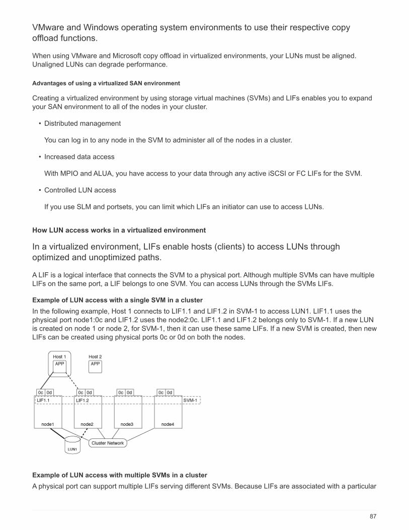
VMware and Windows operating system environments to use their respective copy
offload functions.
When using VMware and Microsoft copy offload in virtualized environments, your LUNs must be aligned.
Unaligned LUNs can degrade performance.
Advantages of using a virtualized SAN environment
Creating a virtualized environment by using storage virtual machines (SVMs) and LIFs enables you to expand
your SAN environment to all of the nodes in your cluster.
• Distributed management
You can log in to any node in the SVM to administer all of the nodes in a cluster.
• Increased data access
With MPIO and ALUA, you have access to your data through any active iSCSI or FC LIFs for the SVM.
• Controlled LUN access
If you use SLM and portsets, you can limit which LIFs an initiator can use to access LUNs.
How LUN access works in a virtualized environment
In a virtualized environment, LIFs enable hosts (clients) to access LUNs through
optimized and unoptimized paths.
A LIF is a logical interface that connects the SVM to a physical port. Although multiple SVMs can have multiple
LIFs on the same port, a LIF belongs to one SVM. You can access LUNs through the SVMs LIFs.
Example of LUN access with a single SVM in a cluster
In the following example, Host 1 connects to LIF1.1 and LIF1.2 in SVM-1 to access LUN1. LIF1.1 uses the
physical port node1:0c and LIF1.2 uses the node2:0c. LIF1.1 and LIF1.2 belongs only to SVM-1. If a new LUN
is created on node 1 or node 2, for SVM-1, then it can use these same LIFs. If a new SVM is created, then new
LIFs can be created using physical ports 0c or 0d on both the nodes.
Example of LUN access with multiple SVMs in a cluster
A physical port can support multiple LIFs serving different SVMs. Because LIFs are associated with a particular
87

SVM, the cluster nodes can send the incoming data traffic to the correct SVM. In the following example, each
node from 1 through 4 has a LIF for SVM-2 using the physical port 0c on each node. Host 1 connects to LIF1.1
and LIF1.2 in SVM-1 to access LUN1. Host 2 connects to LIF2-1 and LIF2-2 in SVM-2 to access LUN2. Both
SVMs are sharing the physical port 0c on the nodes 1 and 2. SVM-2 has additional LIFs that Host 2 is using to
access LUNs 3 and 4. These LIFs are using physical port 0c on nodes 3 and 4. Multiple SVMs can share the
physical ports on the nodes.
Example of an active or optimized path to a LUN from a host system
In an active or optimized path, the data traffic does not travel over the cluster network; it travels the most direct
route to the LUN. The active or optimized path to LUN1 is through LIF1.1 in node1, using physical port 0c. Host
2 has two active or optimized paths, one path to node1, LIF2.1, which is sharing physical port 0c and the other
path to node4, LIF2.4, which is using physical port 0c.
Example of an active or unoptimized path (indirect) path to a LUN from a host system
In an active or unoptimized path (indirect) path, the data traffic travels over the cluster network. This issue
occurs only if all the active or optimized paths from a host are unavailable to handle traffic. If the path from
Host 2 to SVM-2 LIF2.4 is lost, then access to LUN3 and LUN4 traverses the cluster network. Access from
Host 2 uses LIF2.3 on node3. Then the traffic enters the cluster network switch and backs up to node4 for
access to the LUN3 and LUN4. It will then traverse back over the cluster network switch and then back out
through LIF2.3 to Host 2. This active or unoptimized path is used until the path to LIF2.4 is restored or a new
LIF is established for SVM-2 on another physical port on node 4.
88

Considerations for LIFs in cluster SAN environments
You must be aware of certain LIF considerations in a SAN environment.
• Initiators must use Multipath I/O (MPIO) and asymmetric logical unit access(ALUA) for failover capability for
clusters in a SAN iSCSI or FC environment because SAN does not support automatic failover for LIFs.
• At least one SAN LIF of the appropriate protocol must be configured on each node that hosts a mapped
LUN and the node’s HA partner.
You can configure two LIFs per node, one for each fabric being used with FC and to separate Ethernet
networks for iSCSI.
• Some options are not applicable for iSCSI or FC.
For example, you cannot use IP addresses with FC.
Improve VMware VAAI performance for ESX hosts
ONTAP supports certain VMware vStorage APIs for Array Integration (VAAI) features
when the ESX host is running ESX 4.1 or later. These features help offload operations
from the ESX host to the storage system and increase the network throughput. The ESX
host enables the features automatically in the correct environment.
The VAAI feature supports the following SCSI commands:
• EXTENDED_COPY
This feature enables the host to initiate the transfer of data between the LUNs or within a LUN without
involving the host in the data transfer. This results in saving ESX CPU cycles and increasing the network
throughput. The extended copy feature, also known as "copy offload," is used in scenarios such as cloning
a virtual machine. When invoked by the ESX host, the copy offload feature copies the data within the
storage system rather than going through the host network. Copy offload transfers data in the following
ways:
◦ Within a LUN
◦ Between LUNs within a volume
◦ Between LUNs on different volumes within a storage virtual machine (SVM)
89

◦ Between LUNs on different SVMs within a cluster If this feature cannot be invoked, the ESX host
automatically uses the standard READ and WRITE commands for the copy operation.
• WRITE_SAME
This feature offloads the work of writing a repeated pattern, such as all zeros, to a storage array. The ESX
host uses this feature in operations such as zero-filling a file.
• COMPARE_AND_WRITE
This feature bypasses certain file access concurrency limits, which speeds up operations such as booting
up virtual machines.
Requirements for using the VAAI environment
The VAAI features are part of the ESX operating system and are automatically invoked by the ESX host when
you have set up the correct environment.
The environment requirements are as follows:
• The ESX host must be running ESX 4.1 or later.
• The NetApp storage system that is hosting the VMware datastore must be running ONTAP.
• (Copy offload only) The source and the destination of the VMware copy operation must be hosted on the
same storage system within the same cluster.
The copy offload feature currently does not support copying data between VMware
datastores that are hosted on different storage systems.
Determine if VAAI features are supported by ESX
To confirm whether the ESX operating system supports the VAAI features, you can check the vSphere Client or
use any other means of accessing the host. ONTAP supports the SCSI commands by default.
You can check your ESX host advanced settings to determine whether VAAI features are enabled. The table
indicates which SCSI commands correspond to ESX control names.
SCSI command ESX control name (VAAI feature)
EXTENDED_COPY HardwareAcceleratedMove
WRITE_SAME HardwareAcceleratedInit
COMPARE_AND_WRITE HardwareAcceleratedLocking
Microsoft Offloaded Data Transfer (ODX)
Microsoft Offloaded Data Transfer (ODX) overview
Microsoft Offloaded Data Transfer (ODX), also known as copy offload, enables direct
data transfers within a storage device or between compatible storage devices without
90

transferring the data through the host computer.
ONTAP supports ODX for both the SMB and SAN protocols.
In non-ODX file transfers, the data is read from the source and is transferred across the network to the host.
The host transfers the data back over the network to the destination. In ODX file transfer, the data is copied
directly from the source to the destination without passing through the host.
Because ODX offloaded copies are performed directly between the source and destination, significant
performance benefits are realized, including faster copy time, reduced utilization of CPU and memory on the
client, and reduced network I/O bandwidth utilization.
For SAN environments, ODX is only available when it is supported by both the host and the storage system.
Client computers that support ODX and have ODX enabled automatically and transparently use offloaded file
transfer when moving or copying files. ODX is used regardless of whether you drag-and-drop files through
Windows Explorer or use command-line file copy commands, or whether a client application initiates file copy
requests.
Requirements for using ODX
If you plan to use ODX for copy offloads, you need to be familiar with volume support
considerations, system requirements, and software capability requirements.
To use ODX, your system must have the following:
• ONTAP
ODX is automatically enabled in supported versions of ONTAP.
• Minimum source volume of 2 GB
For optimal performance, the source volume should be greater than 260 GB.
• Deduplication
ODX uses deduplication as part of the copy process. If you do not want deduplication on your SVM, you
should disable ODX on that SVM.
• ODX support on the Windows client
ODX is supported in Windows Server 2012 or later and in Windows 8 or later. The Interoperability Matrix
contains the latest information about supported Windows clients.
NetApp Interoperability Matrix Tool
• Copy application support for ODX
The application that performs the data transfer must support ODX. Application operations that support ODX
include the following:
◦ Hyper-V management operations, such as creating and converting virtual hard disks (VHDs), managing
Snapshot copies, and copying files between virtual machines
◦ Windows Explorer operations
◦ Windows PowerShell copy commands
91

◦ Windows command prompt copy commands The Microsoft TechNet Library contains more information
about supported ODX applications on Windows servers and clients.
• If you use compressed volumes, the compression group size must be 8K.
32K compression group size is not supported.
ODX does not work with the following volume types:
• Source volumes with capacities of less than 2 GB
• Sparse volumes
• Read-only volumes
• Semi-thick provisioned volumes
Use cases for ODX
You should be aware of the use cases for using ODX on SVMs so that you can determine
under what circumstances ODX provides you with performance benefits.
Windows servers and clients that support ODX use copy offload as the default way of copying data across
remote servers. If the Windows server or client does not support ODX or the ODX copy offload fails at any
point, the copy or move operation falls back to traditional reads and writes for the copy or move operation.
The following use cases support using ODX copies and moves:
• Intra-volume
The source and destination files or LUNs are within the same volume.
• Inter-volume, same node, same SVM
The source and destination files or LUNs are on different volumes that are located on the same node. The
data is owned by the same SVM.
• Inter-volume, different nodes, same SVM
The source and destination files or LUNs are on different volumes that are located on different nodes. The
data is owned by the same SVM.
• Inter-SVM, same node
The source and destination file or LUNs are on different volumes that are located on the same node. The
data is owned by different SVMs.
• Inter-SVM, different nodes
The source and destination file or LUNs are on different volumes that are located on different nodes. The
data is owned by different SVMs.
• Inter-cluster
The source and destination LUNs are on different volumes that are located on different nodes across
clusters. This is only supported for SAN and does not work for SMB.
92

There are some additional special use cases:
• With the ONTAP ODX implementation, you can use ODX to copy files between SMB shares and FC or
iSCSI attached virtual drives.
You can use Windows Explorer, the Windows CLI or PowerShell, Hyper-V, or other applications that
support ODX to copy or move files seamlessly using ODX copy offload between SMB shares and
connected LUNs, provided that the SMB shares and LUNs are on the same cluster.
• Hyper-V provides some additional use cases for ODX copy offload:
◦ You can use ODX copy offload pass-through with Hyper-V to copy data within or across virtual hard
disk (VHD) files or to copy data between mapped SMB shares and connected iSCSI LUNs within the
same cluster.
This allows copies from guest operating systems to pass through to the underlying storage.
◦ When creating fixed-sized VHDs, ODX is used for initializing the disk with zeros, using a well-known
zeroed token.
◦ ODX copy offload is used for virtual machine storage migration if the source and destination storage is
on the same cluster.
To take advantage of the use cases for ODX copy offload pass-through with Hyper-V, the
guest operating system must support ODX and the guest operating system’s disks must be
SCSI disks backed by storage (either SMB or SAN) that supports ODX. IDE disks on the
guest operating system do not support ODX pass-through.
Special system file requirements
You can delete ODX files found in qtrees. You must not remove or modify any other ODX system files unless
you are told by technical support to do so.
When using the ODX feature, there are ODX system files that exist in every volume of the system. These files
enable point-in-time representation of data used during the ODX transfer. The following system files are in the
root level of each volume that contains LUNs or files to which data was offloaded:
• .copy-offload (a hidden directory)
• .tokens (file under the hidden .copy-offload directory)
You can use the copy-offload delete-tokens -path dir_path -node node_name command to
delete a qtree containing an ODX file.
93

Copyright Information
Copyright © 2022 NetApp, Inc. All rights reserved. Printed in the U.S. No part of this document covered by
copyright may be reproduced in any form or by any means-graphic, electronic, or mechanical, including
photocopying, recording, taping, or storage in an electronic retrieval system- without prior written permission of
the copyright owner.
Software derived from copyrighted NetApp material is subject to the following license and disclaimer:
THIS SOFTWARE IS PROVIDED BY NETAPP “AS IS” AND WITHOUT ANY EXPRESS OR IMPLIED
WARRANTIES, INCLUDING, BUT NOT LIMITED TO, THE IMPLIED WARRANTIES OF MERCHANTABILITY
AND FITNESS FOR A PARTICULAR PURPOSE, WHICH ARE HEREBY DISCLAIMED. IN NO EVENT SHALL
NETAPP BE LIABLE FOR ANY DIRECT, INDIRECT, INCIDENTAL, SPECIAL, EXEMPLARY, OR
CONSEQUENTIAL DAMAGES (INCLUDING, BUT NOT LIMITED TO, PROCUREMENT OF SUBSTITUTE
GOODS OR SERVICES; LOSS OF USE, DATA, OR PROFITS; OR BUSINESS INTERRUPTION) HOWEVER
CAUSED AND ON ANY THEORY OF LIABILITY, WHETHER IN CONTRACT, STRICT LIABILITY, OR TORT
(INCLUDING NEGLIGENCE OR OTHERWISE) ARISING IN ANY WAY OUT OF THE USE OF THIS
SOFTWARE, EVEN IF ADVISED OF THE POSSIBILITY OF SUCH DAMAGE.
NetApp reserves the right to change any products described herein at any time, and without notice. NetApp
assumes no responsibility or liability arising from the use of products described herein, except as expressly
agreed to in writing by NetApp. The use or purchase of this product does not convey a license under any
patent rights, trademark rights, or any other intellectual property rights of NetApp.
The product described in this manual may be protected by one or more U.S. patents, foreign patents, or
pending applications.
RESTRICTED RIGHTS LEGEND: Use, duplication, or disclosure by the government is subject to restrictions
as set forth in subparagraph (c)(1)(ii) of the Rights in Technical Data and Computer Software clause at DFARS
252.277-7103 (October 1988) and FAR 52-227-19 (June 1987).
Trademark Information
NETAPP, the NETAPP logo, and the marks listed at http://www.netapp.com/TM are trademarks of NetApp, Inc.
Other company and product names may be trademarks of their respective owners.
94