Embed Size (px)
Citation preview

/ 002^7FSP Revision No. 0March 19, 1993
Appendix BStandard Operating Procedures
WDCR714/015.51/1 , A R 3 0 I 0 0 9' 1 ' i ->/

FSP Revision No. 0March 19, 1993 ••
Appendix BStandard Operating Procedures
WDCR699/119J1/1 A H 3 0 I O I Q

SOP 1: Soil Boring Drilling and Abandonment
I. PURPOSE AND SCOPE
«
The purpose of this guideline is to describe methods to obtain samples of subsurfacesoil and then backfill boreholes to the surface. .
H. EQUIPMENT AND MATERIALS
• Drilling rig or tripod rig
• Hollow-stem augers (4V4-inch ID)
• Split-spoon samplers
• Downhole compacting tool (e.g., a pipe with a flat plate attached to thebottom)
• Cement
• Bentonite
• Hand augers, stainless steel
III. PROCEDURES AND GUTOELINES
Before sampling begins, equipment will be decontaminated according to theprocedures identified in SOP 6: Decontamination of Drilling Rigs and Equipment.
A H 3 0 I O I I

The location to be sampled is cleared of debris and trash, and the location is notedin the logbook.
Continuous-fight hollow-stem augers with an inside diameter of at least 4.25 nichesare used. The use of water or other fluid to assist in .hollow-stem drilling will beavoided.
The bit of the auger is placed on the ground at the location to be drilled and then
turned with the drilling or soil-coring rig. For split-spoon sampling, the auger isadvanced to a depth just above the top of the interval to be sampled.
Once the auger has been advanced full depth and the last sample obtained, the soilsremoved from the boring will be screened using a portable volatile organics detector.
Soils registering less than 10 ppm in a headspace screening will be returned to theborehole. Soil returned to the borehole will be compacted with the augers in 2-footlifts. The remainder of the borehole is to be grouted to the surface with bentonite-cement grout. The remaining soils are to be drummed and managed as described inSOP 7.
The cement-bentonite grout will be installed continuously in one operation from thebottom of the space to be grouted to the ground surface. When installing grout insoil borings, the grout will be installed through the augers before the augers areremoved.
Samples will be collected from the soil borings at 2-foot intervals. The soil sampleswill be collected from the surface continuously to the water table. Because some ofthe soil samples are being collected for chemical analysis, decontaminated stainlesssteel split-spoon samplers will be used for sample collection. The split-spoonsamplers will be decontaminated according to the procedures outlined in SOP 6.Sample collection will follow the general procedures outlined in SOP 4.
A B 3 0 I O I 2
A tripod drilling rig will be required for boring installation under power lines and
adjacent to railroad tracks. A tripod drilling rig is generally a tripod equipped tocollect continuous samples using a hammer-driven sampler. The soil samplecollection will be the same as that outlined above, except that hollow-stem augersare not used to advance the borehole. Borehole collapse due to soft sediments mayoccur when collecting samples using a tripod drilling rig.
Soil samples will be collected at 1-foot intervals. The soil samples will be placed inclean jars and a headspace measurement of the volatile organics in each of the
samples determined. The headspace measurements will be used to identify the fourpotentially most-contaminated samples which will be submitted for analysis throughthe CLP.
IV. ATTACHMENTS
None.
V. KEY CHECKS AND PREVENTA1TVE MAINTENANCE
Check that the drilling rig or soil-coring rig is hi working order. Check that theborehole is grouted to the ground surface at the completion of drilling and sampling.
WDCR698/010.51
A B 3 0 I O I 3

SOP 2: Shallow Monitoring Wells
I. PURPOSE AND SCOPE
The purpose of this guideline is to describe methods for drilling and installation ofshallow monitoring wells and piezometers within the water table aquifer. Methodsfor drilling and monitoring well installation for deeper wells are presented inProcedure No. 3.
II. EQUIPMENT AND MATERIALS
, Drilling
• Drilling or rig• Hollow-stem augers
*•
Well Riser/Screen
• Polyvinyl chloride (PVC), Schedule 40, minimum 2-inch ID, flush-threadedriser
• Stainless steel, ASTM Type 304, minimum 2-inch ID, flush-threaded riser
• Stainless steel, ASTM Type 304, minimum 4-inch ID, flush-threaded riser
• PVC, Schedule 40, minimum 2-inch ID, flush-threaded, factory slotted screen
A R 3 0 I O U

• Stainless steel, ASTM Type 304 or 316, minimum 2-inch ID, flush-threaded,
wire wound screen
• Stainless steel, ASTM Type 304, minimum 4-inch ID, flush-threaded, wirewound screen
Bottom Cap
• PVC, threaded to match the well screen
• Stainless steel, ASTM type 304, threaded to match the well screen
Centering Guides (if used)
• Same material as the casing, except stainless steel may be used in lieu ofP V C • - . ' • •
Well Cap
• , Above-grade well completion: PVC or stainless steel, threaded or push-ontype, vented
• Flush-mount well completion: PVC or stainless steel, locking, leak-proofseal
Sand
Clean silica sand, provided in factory-sealed bags, well-rounded, containingno organic material, anhydrite, gypsum, mica, or calcareous material; primary(coarse) filter pack, and secondary (fine) filter pack. Gram size determinedbased on sediments observed during drilling.
A H 3 0 I O I 5

Bentonite
• Rure, additive-free bentonite pellets• Pure, additive-free powdered bentonite• Coated bentonite pellets; coating must biodegrade within 7 days
Cement-Bentonite Grout
• Proportion of 6 to 8 gallons of water per 94-pound bag of Portland cement;3 to 10 pounds of bentonite added per bag of cement to reduce shrinkage
Protective Casing
• Above-grade well completion: 6-inch muiunum ID steel pipe with lockingcover, diameter at least 2 inches greater than the well casing, painted withepoxy paint for rust protection; heavy duty lock; protective posts ifappropriate
•
• Flush-mount well completion: Morrison 9-inch or 12-inch 519 manholecover; rubber seal to prevent leakage; locking cover inside of road box
Well Development
• Double surge block with bottom solid, top open, separated by 2 feet ofslotted pipe
• Pump, and associated equipment
• Calibrated meters to measure pH, temperature, and specific conductance
• Containerization for water produced from well
A B 3 0 I O I 6

III. PROCEDURES AND GUIDELINES
A. Drilling Method
Continuous-flight hollow-stem augers with a minimum 6-inch inside diameter(ID) will be used to drill shallow monitoring well boreholes. Split-spoon
>
samples will be collected at selected intervals for chemical analysis and/orlithologic classification. Soil sampling procedures are detailed in SOP 4.
The use of water to assist hi hollow-stem auger drilling for monitoring wellinstallation will be avoided.
Hollow-stem augers, rods, split-spoon samplers, and other downhole drillingtools will be properly decontaminated prior to the initiation of drilling
. activities and between each borehole location. Split-spoon samplers andother downhole soil sampling equipment will also be properlydecontaminated before and after each use. SOP 6 details properdecontamination procedures.
Drill cuttings and decontamination fluids generated during well drillingactivities will be contained according to the procedures detailed in SOP 7.
B. Monitoring Well Installation
Shallow monitoring wells will be constructed through the inside of thehollow-stem augers, once the borehole has been advanced to the desireddepth. If the borehole has been drilled to a depth greater than that at whichthe well is to be set, the borehole will be backfilled with bentonite pellets ora bentonite-cement slurry to a depth approximately 1 foot below the intendedwell depth. Approximately 1 foot of clean sand will be placed on top of thebentonite to return the borehole to the proper depth for well installation.
A B 3 0 I O I 7

The appropriate lengths of well screen, nominally 10 feet (with bottom cap),
and casing will be joined watertight and lowered inside the augers to thebottom of the borehole. Centering guides will be placed around the wellcasing at the bottom of the screen; 5 feet from the top of the screen; and at
40 feet intervals above that.
Selection of the filter pack and well screen intervals for the shallowmonitoring wells shall be made in the field. Based on lithologic samplespreviously obtained at the site, and comparison with samples to be obtainedin the well borings, standard well screen slot of 0.010-inch and silica sandgradations conforming to Morie No. 1 are anticipated.
A primary sand pack (Morie No. 1) consisting of clean silica sand will beplaced around the well screen. The sand will be placed into the borehole ata uniform rate, in a manner that will allow even placement of the sand pack.The augers will be raised gradually during sand pack installation to avoidcaving of the borehole wall; at no time will the augers be raised higher than
the top of the sand pack during installation. During placement of the sand,the position of the top of the sand will be continuously sounded. Theprimary sand pack will be extended from the bottom of the borehole to aminimum height of 2 feet above the top of the well screen. A secondary,finer-grained, sand pack will be installed for a minimum of 1 foot above thecoarse sand pack. Heights of the coarse and fine sand packs and bentoniteseal may be modified hi the field to account for the shallow water table andsmall saturated thickness of the surficial aquifer.
A bentonite pellet seal at least 2 feet thick will.,be placed above the sandpack. The pellets will be placed into the borehole in a manner that willprevent bridging. The position of the top of the bentonite seal will beverified using a weighted tape measure. If all or a portion of the bentoniteseal is above the water table, clean water will be added to hydrate the
5 A I 3 0 I O I 8

bentonite. A hydration period of at least 30 minutes will be allowedfollowing installation of the bentonite seal.
Above the bentonite seal, an annular seal of cement-bentonite grout will beplacec. The cemem-bentonite grout will be installed continuously in oneoperation from the bottom of the space to be grouted to the ground surfacethrough a tremie pipe. The tremie pipe must be plugged at the bottom andhave small openings along the sides of the bottom 1-foot length of pipe.This will allow the grout to diffuse laterally into the borehole and not disturbthe bentonite pellet seal.
For monitoring wells that will be completed above-grade, a locking steelprotective casing set in a concrete pad will be installed. The steel protectivecasing will extend at least 3 feet into the ground and 2 feet above ground.The concrete pad will be square, approximately 3 feet per side. The concretewill be sloped away from the protective casing.
Guard posts may be installed in high-traffic areas for additional protection.Four steel guard posts will be installed around the protective casing, withinthe, edges of the concrete pad. Guard posts will be concrete-filled, at least2 inches in diameter!, and will extend at least 2 feet into the ground and3 feet above the ground. The protective casing and guard posts will bepainted with an epoxy paint to prevent rust.
For monitoring wells with flush-mount completions, Morrison 9-inch or12-inch 519 manhole cover with a rubber-sealed cover and drain will beinstalled. The top of the manhole cover will be positioned approximately1 inch above grade. A square concrete pad, approximately 3 feet per side,will be installed as a concrete collar surrounding the road box cover, and will
slope uniformly downward to the adjacent grade. --The road box and
A B 3 0 I O I 9

installation thereof will be of sufficient strength to withstand normalvehicular traffic.
Concrete pads installed at all wells will be a minimum of 6 inches below
grade and 6 inches above grade. The concrete pad will taper to 6-inchthickness at the edge. Protective casing, guard posts, and flush mounts willbe installed into this concrete.
Each well will be properly labeled on the exterior of the locking cap orprotective casing with a metal stamp indicating the permanent well number.
C. Well Development
Well development will be accomplished using a combination of surgingthroughout the well screen and pumping, until the physical and chemicalparameters of the discharge water that are measured in the field havestabilized and the turbidity of the discharge water is substantially reduced.
Fine-grained materials in the surficial'aquifer at the site, may not allow lowturbidity results to be achieved.
The surging apparatus will include two surge blocks separated byapproximately 2 feet of coarsely slotted pipe. The lower surge block will besolid; the upper surge block will be open and attached to riser pipe leading tothe ground surface. Water will be pumped continuously from the surge blockscreened interval throughout the surging process. The pumping will beaccomplished by airlift induction methods or using a centrifugal pump orequivalent.
Well development will begin by surging the well screen, starting at the
bottom of the screen and proceeding upwards, throughout-the screened zone.
£#301020

Following surging, the well will be pumped to remove the fine materials thathave been drawn into the well. During pumping, measurements of pH,temperature, and specific conductance will be recorded.
Development will continue by alternately surging and pumping until thedischarge water is free from sand and silt, the turbidity is substantiallyreduced, and the pH, temperature, and specific conductance have stabilized atregional background levels, based on historical data. Development willcontinue for a minimum of 30 minutes.
Well development equipment will be decontaminated prior to initial use andafter the development of each well. Decontamination procedures are detailedin SOP 6. Water generated during well development will be contained andmanaged as detailed in SOP 7.
IV. ATTACHMENTS
Schematic diagram of shallow monitoring well construction
WDCR698/011.51
A f i - 3 0 1 0 2 1

6" or 8" Steel LockingProtective Casing
Concrete Pad
10" Minimum BoreholeDiameter
2"- or 4"-ID Schedule 40 PVCor Stainless Steel Well Riser
Expansive Cement Grout
Bentonite Seal
Sand Pack
2"- or 4"-ID Schedule 40 PVCor Stainless Steel 10 Slot WellScreen
Threaded End Plug
A R 3 0 i 0.22TYPICAL SHALLOW MONITORING WELL CONSTRUCTION
Halby Chemical Operable Unit 2 Site
i .• *>. -

SOP 3: Intermediate and Deep Monitoring Wells
I. PURPOSE AND SCOPE
The purpose of this procedure is to outline equipment and methods that will be usedfor deep and intermediate well installation and development.
II. EQUIPMENT AND MATERIALS
Drilling RigWell Casing
• Polyvinyl chloride (PVC), Schedule 40, minimum 2-inch ID, flush-threaded
• Stainless steel, ASTM Type 304, muiimum 2-inch ID, flush-threaded.
•
• Stainless steel, ASTM Type 304, rninimum 4-inch ID, flush-threaded
Well Screen
• PVC, Schedule 40, minimum 2-inch ID, flush-threaded, factory slotted
• Stainless steel, ASTM Type 304, minimum 2-inch ID, flush-threaded, wirewound
• Stainless steel, ASTM Type 304, minimum 4-inch ID, flush-threaded, wirewound
£1301023

Bottom Cap
• PVC, threaded to match the well screen.
• Stainless steel, ASTM Type 304 or 316, threaded to match the well screen.
Centering Guides (if used)
• Same material as the casing, except stainless steel may be used in lieu ofPVC.
Well Cap
• Above-grade well completion: PVC or stainless steel, threaded or push-ontype, vented.
• Flush-mount well completion: PVC or stainless steel, locking, leak-proof« ,
seal.
Sand
• Clean silica sand, provided in factory-sealed bags, well-rounded, containingno organic material, anhydrite, gypsum, mica, or calcareous material; primary(coarse) filter pack, and secondary (fine) filter pack. Gram size determinedbased on sediments observed during drilling.
Bentonite
• Bentonite seal: Pure, additive-free bentonite pellets.• Bentonite for grout: Pure, additive-free powdered bentonite.
A R 3 Q I 0 2 1 *

Cement-Bentonite Grout
• Proportion 6 to 8 gallons of water per 94-pound bag of Portland cement; 3 to10 pounds of bentonite added per bag of cement to reduce shrinkage.
Protective Casing
• Above-grade well completion: Permanent isolation casing with heavy dutylocking cover, painted with epoxy paint for rust protection, heavy duty lock.
• Flush-mount well completion: Morrison 9-inch or 12-inch 519 manholecover; rubber seal for cover; heavy duty locking cap on permanent isolationcasing.
Well Development
• Double surge block with bottom solid, top open, separated by 2 feet ofslotted pipe
• Pump and associated equipment
• Calibrated meters to ensure pH, temperature, and specific conductance
• Containerization for water produced from well
A . R 3 0 I 0 2 5

in. PROCEDURES AND GUIDELINES
A. Drilling Methods
Boreholes for intermediate and deep monitoring well installation will bedrilled in several stages.
Coring, mud rotary drilling, and surface casing installation procedures aredetailed below in separate sections.
. 1. Hollow Steam Auger Drilling
Hollow stem auger drilling techniques will be used to drill boreholesin the intermediate wells for installation of surface isolation casing.8-inch minimum ID HSA will be used to drill the borehole into theaquitard. The boring will be concurrently sampled to confirmidentification of the aquitard. Sampling procedures and frequency areoutlined in the SAP and in SOP 4.
\
The use of water or other fluid to assist in hollow steam drilling is tobe avoided.
The bit of the auger is placed at the ground surface and then turnedwith the soil coring rig. To collect split spoon samples, the auger isadvanced to the top of the sampling depth, and the split-spoon samplecollected from below the auger head. The split spoon is advancedthrough repeated blows from a 140- or 30-pound hammer droppedfrom a height of 30 inches.
A - R 3 0 I 0 2 6

Soil brought to the surface on the outside of the augers should be
containerized at a convenient space away from the working area. Soilmay be stored on plastic sheeting and containerized at the completionof activities at the well cluster.
2. Rotary Drilling
Wet rotary drilling techniques will be employed for installation of
isolation casings and wells in each of the intermediate and deepmonitoring wells. Drilling fluid consisting of water (wet rotary) ofbentonite mud (mud rotary) will be recirculated to bring drill cuttings
to the surface and advance the borehole.
Where the borehole is being advanced from ground surface to theaquitard layer for placement of a 10-inch ID surface casing, theborehole will have a minimum diameter of 14 inches. The boreholewill extend a minimum of 2 feet into the aquitard layer for seating of
the surface casing.
Where the borehole is being reamed out for monitoring wellinstallation through an installed 6-inch intermediate casing, theborehole will have a diameter of 5-7/8 inches.
The bit, drill rods, and other borehole rotary drilling equipment willbe decontaminated prior to the initiation of drilling and between each
borehole location, in accordance with the decontamination proceduresdetailed in SOP 6. Prior to the continuation of rotary drilling inboreholes where a surface casing has been installed, the bit, drill rods,and other downhole rotary drilling equipment will be thoroughlydecontaminated before being inserted into the borehole.
AR.30I027

Drill cuttings and decontamination fluids generated during rotary
drilling activities will be contained according to the proceduresdetailed in SOP 7.
3. Wet Rotary Drilling
Drilling fluids used in wet rotary drilling will consist of potable waterand no additives. The drilling fluid shall be recirculated through theborehole to bring drill cuttings up to the surface and advance theborehole. Drilling mud will be recirculated through the boreholefrom a portable settling basin with a minimum of two vertical settlingbaffles. The settling basin and recirculation system will be of suitableconstruction to avoid leakage or spillage of drilling fluid onto theground adjacent to the borehole.
Wet rotary drilling may not be suitable for all materials at the site.Borehole collapse, non-recovery of drill cuttings, or non-recovery ofdrilling fluids may indicate that drilling using wet rotary techniques isinappropriate. Mud rotary drilling may be substituted for wet rotarytechniques for well installation following discussion with projectmanagement personnel. Mud rotary techniques are not the preferredwell installation techniques of EPA Region III, use of this method isto be considered a last resort after evaluation of the impacts of othertechniques.
4. Mud Rotary Drilling
The water used to create the drilling mud will be potable; a sample ofthe drilling mud will be collected for contaminant analysis prior to thestart of drilling. Only pure, additive-free bentonite will be used toproduce the drilling mud.
6 A R 3 0 I 0 2 8

5. Surface Casing Installation
Surface casing will be constructed of 10-inch or 6-inch ID steel witha minimum wall thickness of 0.20 inches. Casing lengths will be
connected by threaded connections sealed with Teflon tape. The steelcasing and threaded couplings must be free of paint, varnish, or
coatings of any kind, both inside and outside. Threaded connectionsmust be free of any oils or grease. The casing may abe welded
provided the welds meet the Standards of the American WeldingSociety. Surface casing will be decontaminated prior to installation inaccordance with the procedures detailed in SOP 6.
The 10-inch ID surface casing will be installed in a minimum 14-inch
diameter borehole, drilled at least 2 feet into the aquitard layer. Priorto inserting the surface casing into the borehole, drilling fluidcirculation will be continued until the drill cuttings have been
substantially removed from the borehole.
The surface casing will be installed and grouted into place by a groutdisplacement method. The bottom of the surface casing is fitted witha tight, drillable plug. The borehole is then filled with the estimatedvolume of cement-bentonite grout to fill the annular space, and the
casing is lowered to the bottom of the borehole (displacement
method). If the weight of the casing is not sufficient to displace thegrout and allow the casing to sink to the bottom of the borehole, thecasing may be filled with clean water.
After the surface casing installation, the grout will be allowed to setup for at least 12 hours before further drilling proceeds. The casingswill be pressure tested by filling the casing with clean water to withina short distance of the top and pressurizing the casing to
7 A R 3 0 I 0 2 9
approximately 20 psi (net pressure above ambient groundwater). Apressure drop of less than 1 psi in 5 minutes will prove an adequateseal.
B. Monitoring Well Installation
Prior to monitoring well installation in boreholes that have been drilled out
by mud rotary techniques, drilling fluid circulation will be continued until thedrill cuttings have been substantially removed from the borehole. Thedrilling fluid also will be thinned by the addition of clean water in order toallow the proper installation of sand pack and bentonite seal during wellconstruction.
The appropriate lengths of well screen, nominally 10 feet (with bottom cap),and casing will be joined watertight, and lowered to the bottom of the
borehole. Centering guides they will be placed at intervals around the well
casing, at the base of the screen, and 5 feet above the top of the well screen.
Selection of final filter pack and well screen depths for the wells shall bemade in the field.
A primary sand pack consisting of clean Morie No. 1 silica sand will beplaced around the well screen. The sand will be placed into the borehole ata uniform rate, in a manner that will allow even placement of the sand pack.
During placement of the sand, the position of the top of the sand will becontinuously sounded using a stainless steel weight attached to a fiberglass
tape measure. The primary sand pack will be extended from the bottom ofthe borehole to a minimum height of 2 feet above the top of the well screen.A secondary (fine) sand pack will then be installed to a minimum of 1 foot |
above the primary sand pack.
HR30I030

A bentonite pellet seal at least 2 feet thick will be placed above the sand
pack. The pellets will be placed into the borehole in a manner that willprevent bridging. The position of the top of the bentonite seal will be
verified using a weighted tape measure. A hydration period of at least 30minutes will be allowed following installation of the bentonite seal.
Above the bentonite seal, an annular seal of cement-bentonite grout will beplaced. The cement-bentonite grout will be installed continuously in one
operation from the bottom of the space to be grouted to the ground surfacethrough a tremie pipe. The tremie pipe must be plugged at the bottom andhave small openings along the sides of the bottom 1-foot length of pipe.
This will allow the grout to diffuse laterally into the borehole and not disturbthe bentonite pellet seal.
For monitoring wells that will be completed above-grade, the surface casing
itself will serve as the protective casing. The surface casing will be finished2 to 3 feet above grade and fitted with a locking steel cap. A concrete pad
with four guard posts will be installed.
The concrete pad will be square, approximately 3 feet per side, poured intowooden forms. The concrete will be sloped away from the protective casing.The concrete pad will extend at least 6 inches below and 6 inches above the
ground surface.
Four steel guard posts will be installed around the locking casing, within theedges of the concrete pad. Guard posts would be concrete-filled, at least 2inches in diameter, and would extend at least 2 feet into the ground and 3
feet above the ground. The protective casing and guard posts will be paintedwith an epoxy paint to prevent rust.
A R 3 0 I 0 3 !

For monitoring wells with flush-mount completions, a Morrison 519 manholecover with a rubber-sealed cover and drain will be installed. The top of themanhole will be positioned approximately 1 inch above grade. A squareconcrete pad, approximately 3 feet per side, will be installed as a concretecollar surrounding the road box cover, and will slope uniformly downward tothe adjacent grade. The road box and installation thereof will be of sufficientstrength to withstand normal vehicular traffic. The concrete pad will extendat least 12 inches below the ground surface.
Inside the manhole, a locking cap will be placed over the permanent casing.
Each well will be labeled on the exterior of the locking cap with a metalstamp indicating the permanent well number.
C. Well Development
Well development will be accomplished using the same techniques described Iin SOP 2.
IV. ATTACHMENTS
Schematic Diagram of Intermediate/Deep Monitoring Well Construction
WDCR698/012.51
10 A R 3 0 I 0 3 2

Locking Cap Vented PVC Cap
1 \/L
X X
X X
X
X
X
xX
X
X
X
X
x
X
X
X
X
X
xX
X
X
•MM
1•iX
X
X
X
xX
X
X
X
XX
xX
X
xX
X
X
X
xX
X
X
X
X
xX
xxX
X
X
X
X
X
xX
\xXxX
XXx(•ft
III^'£r*»p*l
f*t• %'p*l
fe5j;ft
n
^
^^^
^ •H
•H^WH•••HH
s«M*MHUM
•
TX
Xf^\x
X
X
X
X
X
X
X
sX
X
X
X
X
X
\X
X
xX
X
/\
v Jx
^x.^ ^\
»» <^ ^/ V
/ ,\/ *\^\^
Hi1I*
8*'>I'1I"1
l»f!3
Guardposts (4)
„ 0Xnfm ^
X Ground Surfacei/XVxV^vl^ ——— Concrete Pad
X \X X .,y
X \X X
X XX X .\ \x x
X X
X-X Xx
• *X X
X XX X
X X^ x\ X
X XN Xx x\ \Vxx x
X XX X
X XX X
MMH
——— 6-Inch ID Carbon SteelIsolation Casing
^F~^— Bottom 10-Inch Borehole
Bottom 6-Inch Casing
————— 2-Inch ID Schedule 40 PVC Riser Pipe
< ————— Bentonite Seal
< ————— 5 7/8-Inch Borehole
————— Clean Silica-Sand Pack
————— 2-Inch ID 0.010-Inch SlotSchedule 40 PVC Well Screen
-Threaded PVC End Plug
A R 3 0 J 0 3 3
TYPICAL WELL CONSTRUCTION DETAILSFOR A WELL WITH ISOLATION CASINGHalby Chemical Operable Unit 2 Site

SOP 4: Soil Sampling
I. PURPOSE AND SCOPE
The purpose of this procedure is to provide guidelines for obtaining samples ofsurface and subsurface soils using hand and drilling-rig mounted equipment.
II. EQUIPMENT AND MATERIALS
• Stainless-steel trowel, shovel, scoopula, coring device, trier, handauger, or other appropriate hand tool
• Stainless-steel, split-spoon samplers
• Thin-walled samplers (e.g., Shelby tubes)
• Drilling rig or soil-coring rig
• Stainless-steel pan or bowl
• Scoopula or other appropriate hand tool
• Sample bottles
AR30 I031*

HI. PROCEDURES AND GUIDELINES
A. Surface Sampling
Before sampling begins, equipment will be decontaminated using the
procedures described in SOP 6: Decontamination of Drilling Rigs andEquipment. The sampling point is located and recorded in the field logbook.
Debris should be cleared from the sampling location.
A shovel, post-hole digger, or other tool can be used to remove soil to apoint just above the interval to be sampled. A decontaminated sampling toolwill be used to collect the sample when the desired sampling depth has beenreached. The sampling tool should be stainless steel and decontaminated inaccordance with the procedures outlined in SOP 6. Soil for semivolatileorganic and inorganic analyses is placed in the bowl and mixed; soil for
volatile organic analysis is not mixed or composited but is placed directlyinto the appropriate sample bottles. A stainless-steel or dedicated wooden
tongue depressor is used to transfer the sample from the bowl to the
container.
The soils removed from the borehole should be visually described in the fieldlog book, including approximated depths.
When sampling is completed, flame ionization device (FID) readings shouldbe taken directly above the hole, and the hole is then backfilled. Aftersampling the collected samples are labeled and handled as described inSOP 23.
A R 3 0 I 0 3 5

B. Split-Spoon Sampling
By use of a drilling rig at other soil boring locations, a hole is advanced to
the desired depth. For split-spoon sampling, the samples are then collectedfollowing the ASTM D 1586 standard (attached). The sampler is loweredinto the hole and driven to a depth equal to the total length of the sampler;
typically this is 24 inches. The sampler is driven in 6-inch increments usinga 140-pound weight ("hammer") dropped from a height of 30 inches. To
obtain enough volume of sample for subsequent laboratory analysis, use of a3-inch ID sampler may be required. Blow counts obtained with a 3-inch ID
spoon would not conform to ASTM D 1586 and would therefore not be used
for geotechnical evaluations. The number of hammer blows for each 6-inchinterval is counted and recorded.
Once retrieved from the hole, the sampler is carefully split open. Careshould be taken not to allow material in the sampler to fall out of the openend of the sampler. To collect the sample, the surface of the sample should
be removed with a clean tool and disposed of. Samples collected forvolatiles analysis should be placed directly into the sample containers fromthe desired depth in the split spoon. Material for collection of samples for allother parameters should be removed to a decontaminated stainless steel tray.The sample for non-volatiles analysis should be homogenized in the field by
breaking the sample into small pieces, and removing gravel. Thehomogenized sample should be placed in the sample containers. If samplevolume requirements are not met by a single sample collection, additionalsample may be collected by collecting a sample from below the sample, andcompositing the sample for non-volatile parameters only.
Split-spoon samples also will be collected using a tripod rig. When using atripod rig the soil samples are collected using an assembly similar to thatused with the drilling rigs.
A R 3 0 I 0 3 6

C. Shelby Tube Sampling
Thin-walled samplers are advanced hydraulically by continuous pressure froma drilling rig. ASTM D 1587 is the standard for this method. At the end ofthe designated push interval and before lifting the sample, the sampler istwisted to break the bottom of the sample.
Upon recovery of the sampler, the actual length of the sample is measured
and recorded, excluding slough or cuttings. At least 1/2-inch of soil iscleaned from each end of the sampler. The soil that has been cleaned fromthe sample can be used for visual classification.
Each end of the sampler is waxed. After the initial sealing, a filler (e.g.,
paper or sand) can be placed hi the remaining open area of the sampleravoid breaking of the initial end seals. The ends of the sampler areclosed with tight-fitting metal or plastic caps, and the seam between the cap
and sampler is taped. The ends of the sampler may be dipped in hot wax tocompletely cover the tape and seal the sampler. The sample and the top capare labeled with appropriate information, including the designation of theboring, the date and time of sampling, the sample number, and pertinentinformation about the collection of the sample. The side of the sampler is
marked as to which end is the top and which is the bottom. The samplershould be carried gently and kept in an upright, vertical position as much as
possible to maintain the in situ orientation and to minimize sampledisaggregation.
IV. ATTACHMENTS
A R 3 0 I 0 3 7

V. KEY CHECKS AND PREVENTATIVE MAINTENANCE
Check that decontamination of equipment is thorough. Check that sample collection
is swift to avoid loss of volatile organics during sampling. When collecting samplesusing thin-walled samplers, check that the pressure is applied smoothly andcontinuously, not in a jolting fashion.
WDCR698/013.51
A R 3 0 I 0 3 8

SOP 5: Soil Characterization
I. PURPOSE AND SCOPE
This SOP provides guidance to obtain accurate and consistent descriptions of soilcharacteristics during soil-sampling operations. The characterization is based onvisual examination and manual tests, not on laboratory determinations.
II. EQUIPMENT AND MATERIALS
• Indelible pens
• Tape measure or ruler• Field logbook• Spatula
• HCL, 10 percent solution• Squirt bottle with water
• Rock- or soil-color chart• Grain-size chart• Hand lens
III. PROCEDURES AND GUTOELINES
This section covers several aspects of the soil characterization: instructions forcompleting the CH2M HILL soil boring log Form 1586, field classification of soil,and standard penetration test procedures.
A R 3 0 I 0 3 9

Instructions for Completing Soil Boring Logs
Soil boring logs will be completed in the field log books. Information collected will be
consistent with that required for Form D1586, a standard CH2M HILL form.
The information collected in the field to perform the soil characterization is described
below.
Field personnel should review completed logs for accuracy, clarity, and thoroughness of
detail. Samples also should be checked to see that information is correctly recorded on
both jar lids and labels and on the log sheets.
Heading Information
Boring/Well Number. Enter the boring/well number. A numbering system should b\chosen that does not conflict with information recorded for previous exploratory work
done at the site. Number the sheets consecutively for each boring.
Location. If stationing, coordinates, mileposts, or similar project layout information is
available, indicate the position of the boring to that system using modifiers such as"approximate" or "estimated" as appropriate.
Elevation. Elevation will be determined at the conclusion of field activities.
Drilling Contractor. Enter the name of the drilling company and the city and state
where the company is based.
Drilling Method and Equipment. Identify the bit size and type, drilling fluid (if
used), and method of drilling (e.g., rotary, hollow-stem auger). Information on thedrilling equipment (e.g., CME 55, Mobile B61) also is noted.
A R 3 0 I O U O

Water Level and Date. Enter the depth below ground surface to the apparent waterlevel in the borehole. The information should be recorded as a comment. If free wateris not encountered during drilling or cannot be detected because of the drilling method,this information should be noted. Record date and time of day (for tides, river stage) ofeach water level measurement.
Date of Start and Finish. Enter the dates the boring was begun and completed. Timeof day should be added if several borings are performed on the same day.
Logger. Enter the first initial and full last name.
Technical Data
Depth Below Surface. Use a depth scale that is appropriate for the sample spacing andfor the complexity of subsurface conditions.
Sample Interval. Note the depth at the top and bottom of the sample interval.
Sample Type and Number. Enter the sample type and number. For instance, S-l =
split spoon, first sample. Number samples consecutively regardless of type. Enter asample number even if no material was recovered in the sampler.
Sample Recovery. Enter the length to the nearest 0.1 foot of soil sample recoveredfrom the sampler. Often, there will be some wash or caved material above the sample;do not include the wash material in the measurement.
Standard Penetration Test Results. In this column, enter the number of blowsrequired for each 6 inches of sampler penetration and the "N" value, which is the sum of
the blows in the middle two 6-inch penetration intervals. A typical standard penetrationtest involving successive blow counts of 2, 3, 4, and 5 is recorded as 2-3-4-5 and (7).
The standard penetration test is terminated if the sampler encounters refusal. Refusal isa penetration of less than 6 inches with a blow count of 50. A partial penetration of 50blows for 4 inches is recorded as 50/4 inches.
A'R30IOM

Sample may be collected using a 300-pound hammer or 3-inch-diameter split-spoon
samples at the site. Use of either of these sample collection devices invalidates standardpenetration test results and should be noted in the comments section of the log. The
300-pound hammer should only be used for collection of 3-inch-diameter split-spoonsamples. Blow counts should be recorded for collection of samples using either a 3-inch
split-spoon, or a 300-pound hammer. An "N" value need not be calculated.
Soil Description. The soil classification should follow the format described in the"Field Classification of Soil" subsection.
Comments. Include all pertinent observations (changes in drilling fluid color, rod
drops, drilling chatter, rod bounce as in driving on a cobble, damaged Shelby tubes, and
equipment malfunctions). In addition, note if casing was used, the sizes and depthsinstalled, and if drilling fluid was added or changed. You should instruct the driller toalert you to any significant changes in drilling (changes in material, occurrenceboulders, and loss of drilling fluid). Such information should be attributed to the drillerand recorded in this column.
Specific information might include the following:
• The date and the time drilling began and ended each day
• The depth and size of casing and the method of installation
• The date, time, and depth of water level measurements
• Depth of rod chatter
• Depth and percentage of drilling fluid loss
• Depth of hole caving or heaving
4 A R 3 0 I O i * 2

Table 4RELATIVE DENSITY OF COARSE-GRAINED SOIL
Blows/Ft
0 - 4
5 - 10
11-30
31 -50
>50
Relative Density
Very loose
Loose
Medium
Dense
Very dense
Field Test
Easily penetrated with 1/2- in steel rodpushed by handEasily penetrated with 1/2-in steel rodpushed by hand
Easily penetrated with 1/2-in steel roddriven with 5-lb hammer
Penetrated a foot with 1/2-in steel roddriven with 5-lb hammer
Penetrated only a few inches with 1/2-insteel rod driven with 5-lb hammer
Table 5CONSISTENCY OF FINE-GRAINED SOIL
Blows/Ft
<2
2 - 4
5 - 8
9- 15
16-30
>30
Consistency
Very soft
Soft
Firm
Stiff
Very stiff
Hard
Field Test
Easily penetrated several inches by fist; sagsunder own weight
'Easily penetrated several inches by thumb;easily pinched hi two between thumb andforefinger
Can be penetrated several inches by thumbwith moderate effort
Readily indented by thumb, but penetratedonly with great effort
Readily indented by thumbnail; barelyimprinted by pressure from fingersIndented with difficulty by thumbnail;cannot be imprinted by fingers
WDCR698/017.51
f l R 3 0 I O l * 3

SOP 6: Decontamination ofDrilling Rigs and Equipment
I. PURPOSE AND SCOPE
The purpose of this guideline is to provide methods for the decontamination ofdrilling rigs; monitoring well materials; downhole drilling tools; soil, sediment and
water sampling equipment; and water-level measurement equipment. Personneldecontamination procedures are not addressed in this SOP; refer to the site safety
plan. Sample bottles will not be field decontaminated, but purchased with cleaningcertified by the manufacturer.
II. EQUIPMENT AND MATERIALS
• Portable steam cleaner and related equipment• Potable water• Phosphate-free detergent such as Alconox or Liquinox
• Buckets• Brushes
• Distilled organic-free water• Methanol, pesticide grade• Hexane, pesticide grade• Six-molar nitric acid, analytical grade• HPLC-grade water• Aluminum foil
A R 3 Q I O H

III. PROCEDURES AND GUIDELINES
A. Drilling Rigs and Monitoring Well Materials
Prior to the onset of drilling, after each borehole, prior drilling throughpermanent isolation casing, and prior to leaving the site, heavy equipment
and machinery will be decontaminated by steam cleaning at a designatedarea. The steam cleaning area will be designed to contain decontaminationwastes and waste waters and can be a HDPE-lined, bermed pad. A pumping
system will be used to convey decontaminated water from the pad to drums.
Well casings and screens shall be delivered to the site previouslydecontaminated with accompanying written certification by the factory ormanufacturer attesting to decontamination procedures. Factory rinsate test*results for parameters selected for the site shall be included. Well casings
and screens may be steam cleaned in the field if they are exposed tocontamination at the site prior to use.
B. Downhole Drilling Tools
Downhole tools will be steam cleaned prior to the onset of drilling, prior todrilling through permanent isolation casing, and between boreholes. This
will include, but is not limited to, rods, split-spoon or similar samplers,coring equipment, augers, and casing.
Prior to the use of a sampling device such as a split-spoon sampler for thecollection of a soil sample for physical characterization, the sampler shall becleaned by scrubbing with a detergent solution followed by a potablerinse.
A R 3 0 I O U 5

Prior to the use of a sampling device such as a split-spoon sampler for the
collection of a soil sample for chemical analysis, the sampler shall bedecontaminated following the procedures outlined in the followingsubsection.
C. Soil, Sump, and Water Sampling Equipment
Prior to the initiation of field sampling, the soil, sump, and water samplingequipment will be decontaminated using the following procedures:
1. Wash and scrub equipment with phosphate-free detergent.
2. Rinse equipment with distilled organic-free water.
3. Rinse equipment with a 10 percent methanol solution.
4. Rinse equipment with distilled organic-free water.
5. Rinse equipment with 10 percent 6-molar nitric acid solution (ifsampling for metals).
6. Rinse equipment with distilled organic-free water.
7. (Optional) rinse equipment with HPLC-grade water.
8. Allow equipment to air dry.
9. Wrap the equipment with aluminum foil, shiny side out, to preventcontamination during storage and transport.

The decontamination procedure for positive-displacement groundwatersampling pumps is similar except that Steps 5 and 6 are omitted. The pump
will be placed in an upright decontamination tube, and the water andmethanol rinses, a minimum of one gallon of each, will be pumped throughthe pump and the length of discharge tubing. The outside of the tubing will
be decontaminated using the same rinse solutions.
Disposable field filters will be used; decontamination is not required.
D. Field Analytical Equipment
1. Water Level Indicators
Water level indicators that consist of a probe that comes into contactwith the groundwater must be decontaminated using the following
steps:
a. Rinse with tap waterb. Rinse with deionized waterc. Solvent rinse with methanold. Rinse with deionized water
2. Probes
Probes, for example, pH or specific ion electrodes, geophysicalprobes, or thermometers that would come in direct contact with thesample, will be decontaminated using the procedures specified aboveunless manufacturer's instructions indicate otherwise. For probes thatmake no direct contact, for example, OVA equipment, the probe
be wiped with clean paper-towels or cloth wetted with methanol.
A R 3 0 I O i » 7
IV. ATTACHMENTS
None.
V. KEY CHECKS AND PREVENTATIVE MAINTENANCE
The effectiveness of field cleaning procedures shall be monitored by rinsing fieldcleaned equipment with organic-free water and submitting the rinse water in standardsample containers for analysis. Any time a sampling event occurs, at least one suchquality control sample shall be collected. The total number of equipment blanks willbe at least 5 percent of the number of samples collected during large-scale field
sampling efforts.
At least one piece of field equipment shall be selected for this procedure each timeequipment is washed. An attempt should be made to select different pieces ofequipment for this procedure.
WDCR698/018.51
• Depth of change in material
• Drilling interval through a boulder
Field Classification of Soil
This section presents the format for the field classification of soil. In general, theapproach and format for classifying soils should conform to ASTM D 2488-90, Visual-Manual Procedure for Description and Identification of Soils.
The Unified Soil Classification System is based on numerical values of certain soilproperties that are measured by laboratory tests (ASTM D 2487). It is possible,
however, to estimate these values in the field with reasonable accuracy using visual-manual procedures (ASTM D 2488-90, attached). In addition, some elements of a
complete soil description, such as the presence of cobbles or boulders, changes in strata,and the relative proportions of soil types in a bedded deposit, can be obtained only in
the field.
Soil descriptions should be precise and comprehensive without being verbose. Thecorrect overall impression of the soil should not be distorted by excessive emphasis on
insignificant details. In general, similarities rather than differences between consecutivesamples should be stressed.
Soil descriptions must be recorded for every soil sample collected. The format andorder for soil descriptions should be as follows:
1. Soil name (synonymous with ASTM D 2488-90 Group Name) with appropriatemodifiers
2. Group symbol
3. Color

4. Moisture content
5. Relative density or consistency
6. Soil structure, mineralogy, or other descriptors
This order follows, in general, the format described in ASTM D 2488-90.
Soil Name
The basic name of a soil should be the ASTM D 2488-90 Group Name on the basis ofvisual estimates of gradation and plasticity. The soil name should be capitalized.
Examples of acceptable soil names are illustrated by the following descriptions:
• A soil sample is visually estimated to contain 15 percent gravel,55 percent sand, and 30 percent fines (passing No. 200 sieve). The fines
are estimated as either low or highly plastic silt. This visual
classification is SILTY SAND WITH GRAVEL, with a Group Symbolof (SM).
• Another soil sample has the following visual estimate: 10 percentgravel, 30 percent sand, and 60 percent fines (passing the No. 200 sieve).
The fines are estimated as low plastic silt. This visual classification isSANDY SILT. The gravel portion is not included in the soil name
because the gravel portion was estimated as less than 15 percent. TheGroup Symbol is (ML).
The gradation of coarse-grained soil (more than 50 percent retained on No. 200 sieve) isincluded in the specific soil name in accordance with ASTM D 2488-90. There is nneed to further document the gradation. However, the maximum size and angularity or
roundedness of gravel and sand-sized particles should be recorded. For fine-grained soil
6 A R 3 0 I 0 5 0

(50 percept or more passing the No. 200 sieve), the name is modified by the appropriateplasticity/elasticity term in accordance with ASTM D 2488-90.
Interlayered soil should each be described starring with the predominant type. Anintroductory name, such as "Interlayered Sand and Silt," should be used. In addition,the relative proportion of each soil type should be indicated (see Table 1 for example).
Where helpful, the evaluation of plasticity/elasticity can be justified by describing resultsfrom any of the visual-manual procedures for identifying fine-grained soils, such as
reaction to shaking, toughness of a soil thread, or dry strength as described in ASTM D2488-90.
Group Symbol
The appropriate group symbol from ASTM D 2488-90 must be given after each soil
name. The group symbol should be placed in parentheses to indicate that theclassification has been estimated.
In accordance with ASTM D 2488-90, dual symbols (e.g., GP-GM or SW-SC) can beused to indicate that a soil is estimated to have about 10 percent fines. Borderlinesymbols (e.g., GM/SM or SW/SP) can. be used to indicate that a soil sample has been
identified as having properties that do not distinctly place the soil into a specific group.Generally, the group name assigned to a soil with a borderline symbol should be thegroup name for the first symbol. The use of a borderline symbol should not be usedindiscriminately. Every effort should be made to first place the soil into a single group.Grain size is estimated in accordance with ASTM D 2488-90 (Table 2).
Color
The color of a soil must be given. The color description should be based on the
Munsell system. The color name and the hue, value, and chroma should be given.
A R 3 0 I 0 5 I

Moisture Content*
The degree of moisture present in a soil sample should be defined as dry, moist, or wet.Moisture content can be estimated from the criteria listed on Table 3.
Relative Density or Consistency
Relative density of a coarse-grained (cohesionless) soil is based on N-values (ASTM D1586-84, attached to SOP 4). If the presence of large gravel, disturbance of the sample,or non-standard sample collection makes determination of the in situ relative density or
consistency difficult, then this item should be left out of the description and explained inthe Comments column of the soil boring log.
Consistency of fine-grained (cohesive) soil is properly based on results of pocketpenetrometer or torvane results. In the absence of this information, consistency canestimated from N-values. Relationships for determining relative density or consistencyof soil samples are given in Tables 4 and 5.
Soil Structure, Mineralogy, and Other Descriptors
Discontinuities and inclusions are- important and should be described. Such featuresinclude joints or fissures, slickensides, bedding or laminations, veins, root holes, andwood debris;
Significant mineralogical information such as cementation, abundant mica, or unusualmineralogy should be described.
Other descriptors may include particle size range or percentages, particle angularity orshape, maximum particle size, hardness of large particles, plasticity of fines, drystrength, dilatancy, toughness, reaction to HC1, and staining, as well as other informationsuch as organic debris, odor, or presence of free product.
A R 3 0 I 0 5 2

Equipment and Calibration
Before starting the testing, the equipment should be inspected for compliance with the
requirements of ASTM D 1586-84. The split-barrel sampler should measure 2-inch or3-inch O.D., and should have a split tube at least 18 inches long. The minimum size
sampler rod allowed is "A" rod (1-5/8-inch O.D.). A stiffer rod, such as "N" rod(2-5/8-inch O.D.), is required for depths greater than 50 feet. The drive weight
assembly should consist of a 140-pound or 300-pound hammer weight, a drive head, anda hammer guide that permits a free fall of 30 inches.
IV. ATTACHMENTS
ASTM D 2488-90: Standard Practice for Description and Identification of Soils (Visual-Manual Procedures).
V. KEY CHECKS AND PREVENTIVE MAINTENANCEi
Check entries to the soil-boring log and field logbook in the field; because the sampleswill be disposed of at the end of fieldwork, confirmation and corrections cannot bemade later. Check that sample numbers and intervals are properly specified. Check thatdrilling and sampling equipment is decontaminated using the procedures defined in SOP9: Decontamination of Drilling Rigs and Equipment.
WDCR698/014.51
A R 3 0 I 0 5 3

Table 2GRAIN SIZE CLASSIFICATION (ASTM D-2488)
Size (mm)
>30075-300
19-75
4.75-19
2-4.75
0.425-2
0.075-0.425
<0.075
Name
boulder
cobblecoarse gravel
fine gravelcoarse sand
medium sand
fine sand
silt & clay
Table 3CRITERIA FOR DESCRIBING MOISTURE CONDITION
Description Criteria
Dry Absence of moisture, dusty, dry to the touch
Moist Damp, but no visible water; can be molded
Wet Visible free water; usually soil is below water table
WDCR698/016.51
AR30I05I4

SOP 7: Disposal of Fluids and Solids
I. PURPOSE AND SCOPE
The purpose of this guidance is to describe the procedures to dispose of hazardousfluid and solid materials generated as a result of the field operations performed at the
site. This SOP does not provide guidance on the details of Department ofTransportation regulations pertaining to the transport of hazardous wastes; the
appropriate Code of Federal Regulations (49 CFR 171 through 177) should bereferred to.
II. EQUIPMENT AND MATERIALS
A. Fluids
• 55-gallon steel drums• Tools for securing drum lids
• Funnel for transferring liquid into drum
• Labels• Marking pen for appropriate labels• Seals for 55-gallon steel drums
B. Solids
• 55-gallon steel drums• Tools for securing drum lids
• Plastic sheets• Labels
• , Marking pen for appropriate labels
A R 3 0 I 0 5 5

HI. PROCEDURES AND GUIDELINES
A. Methodology
Empty, clean drums will be brought to the site by the drilling subcontractorfor soil and groundwater collection and storage. The empty drums will belocated at the field staging area and moved to drilling locations as required.The drums will be filled with the drilling and well installation wastes,capped, sealed, and moved to the onsite drum storage area by the drillingsubcontractor. The full drums will separate types of wastes by media. Thedrums will be labeled as they are filled in the field and labels indicating thatthe contents are potentially hazardous affixed. Soils registering less than 10
ppm with the OVA in a headspace screening will not be drummed, but willbe spread at the boring location and left.
The contents of the drums will be sampled to determine the disposalrequirements of the drilling wastes. The drum sampling will beaccomplished through the collection and submittal of composite samples as aseries of 10 drums containing the same media. The compositing of thesample will be accomplished through the collection of a specific volume ofthe material in each drum into a large sample container. When samples fromeach of the drums being sampled in a single compositing are collected, thesample will be submitted for TCLP analysis through the CLP. The TCLPanalysis will be used to determine if drilling wastes are covered by landdisposal restrictions.
AR30 I056

The test was started by rapidly removing the displacement device, which causes adrop in the water level. The data logger begins recording the water level and
elapsed time when the preset trigger amount is reached. Readings are taken asabove, and the test stopped when the well has recovered to 90 percent of the originallevel.
At the end of each day, the test results will be transferred to a computer disk. The
computer will be attached to the data logger and the data downloaded and checkedfor preliminary completeness.
IV. ATTACHMENTS
None.
V. KEY CHECKS AND PREVENTIVE MAINTENANCE
Check that the packer assembly is in good condition and not leaking. Provide a
repair kit including tape and clamps. Take additional packer assembly and otherspare parts.
Check the batteries for the datalogger and computer. Check that the computer diskscontaining the programs for the datalogger are packed. Include blank computerdisks for file storage.
Check the datalogger calculation of the well hydraulic conductivity at the end ofeach test to determine if these are consistent with expectations.
WDCR701/017.51
A R 3 0 I 0 5 7

B. Labels
Drums and other containers used for storing wastes from drilling operations
will be labeled when accumulation in the container begins. Labels willinclude the following minimum information:
• Container number
• Container contents
• Origin (source area including individuals wells, piezometers,
and soil borings)
• Date that accumulation began
• Date that accumulation ended
When laboratory results are received, drum labels will be completed orrevised to indicate the hazardous waste constituents in compliance withTitle 40 of the Code of Federal Regulations, Part 262, Subpart C.
C. Fluids
Drilling fluids generated during soil boring and groundwater dischargedduring development and purging of the monitoring wells will be collected in55-gallon, closed-top drums. When a drum is filled, the bung will be securedtightly.
A R 3 0 I 0 5 8

When development and purging is completed, the water will be tested forappropriate hazardous waste constituents. A portion sample will be obtainedfrom each drum. A composite sample from 10 drums will be submitted tothe CLP for analysis for disposal parameters.
D. Solids
Most of the volume of solids to be disposed of is made up of soil cuttingsfrom well and boring drilling.
Solids also will include plastic sheeting used for decontamination pads,tyveks, disposable sampling materials, and any other disposable material used
during the field operations that appears to be contaminated. These materialswill be placed in designated drums.
E. Storage and Disposal
The wastes generated at the site at individual locations will be transported tothe fenced drum storage area by the drilling services subcontractor.
Waste solid materials that contain hazardous constituents will be disposed ofat an offsite location in a manner consistent with applicable solid waste,hazardous waste, and water quality regulations. Transport and disposal willbe performed by a commercial firm under subcontract.
The liquid wastes meeting acceptable levels of discharge contamination willbe disposed of through the sanitary sewer system at the site. Prior todisposal to the sanitary sewer system, contract arrangements will be madewith the appropriate authorities. Wastes exceeding acceptable levelsdisposal through the sanitary sewer system will be disposed of throughcontract with a commercial transport and disposal firm.
A R 3 0 I 0 5 9

IV. KEY CHECKS AND PREVENTATIVE MAINTENANCE
Check that representative samples of the drummed materials are obtained.
WDCR698/019.51
A R 3 0 I 0 6 0

SOP 8: Surface Water Sampling
I. PURPOSE AND SCOPE
This procedure presents the techniques used in collecting surface water samples.
II. MATERIALS AND EQUIPMENT
Materials and equipment vary depending on type of sampling. More detail is found
in Section III text.
• Open tube sampler• Dip sampler
• Weighted bottle sampler
• Hand pump• Kemmerer or Van Dorn sampler• Depth-integrating sampler• Sample containers
• Meters for specific conductance, temperature, pH, and dissolved oxygen
in. PROCEDURES AND GUIDELINES
Before surface water samples are taken, all sampler assemblies and sample containers
are cleaned and decontaminated as described hi SOP 6. All sample bottles arelabeled and handled in accordance with SOP 23. Method for taking surface watersamples are described below.
A R 3 0 I 0 6 I

A. Manual Sampling
Surface water samples are taken manually by submerging a clean glass,stainless steel, or Teflon container into the water body. Samples may betaken at depth with a covered bottle that can be removed with a tripline. The
most common sampler types are beakers, scalable bottles and jars, pondsamplers, and weighted bottle samplers. Pond samplers have a fixed or
telescoping pole attached to the sample container. Weighted bottle samplersare lowered below water surface, where the attached bottle is opened,
allowed to fill, and pulled out of the water. When retrieved, the bottle istightly capped and removed from the sampler assembly. Specific types ofweighted bottle samplers include dissolved oxygen, Kemmerer, or Van Dorn,
and are acceptable in most instances.
A sample is taken with the following specific steps:
1 . The location and desired depth for water sampling are selected.
2. The sample site is approached from downstream in a manner that
avoids disturbance of bottom sediments as much as possible. Thesample bottle is gently submerged to just below the water surfacewith the mouth pointed upstream and the bottle tilted slightly
downstream. Bubbles and floating materials should be preventedfrom entering the bottle.
3. For weighted bottle samplers, the assembly is slowly lowered to thedesired depth. The bottle stopper is unseated with a sharp tug and the
bottle is allowed to fill until bubbles stop rising to the surface.
4. When the bottle is full, it is gently removed from the water. Ifsample transfer is required, it should be performed at this time.
2 A R 3 0 I 0 6 2

B. Mechanical Sampling
Mechanical surface water sampling involves a peristaltic pump that conveyswater through heavy-walled tubing to a container. The tubing must be
flexible and made of a non-reactive material such as Tygon or Teflon; Teflonis usually selected when oil and grease are present. Medical-grade or silicon
tubing may be satisfactory in some cases, depending on the constituents to beanalyzed. An external power source may be required, but many peristalticpumps are equipped with batteries.
In some situations, it may be desirable or necessary to locate the container
between the water intake and the pump connection. The peristaltic pumpmay then be used as a vacuum pump. The vacuum pump method cannot be
used for samples on which analyses for volatile organic compounds (VOCs)will be conducted, as it very effectively strips VOCs from water.
When sampling at depths or in fast currents, the inlet tubing is weighted or
attached to some stationary object such as a bridge piling or a pole stuck hibottom sediments. Weighting the tubing can cause stretching and reduce theinside tubing diameter, which reduces pump capacity. Insertion of a pole
into bottom sediments adds particulates to the water column. Water sampling
should not commence until particulates have settled.
The following steps are taken hi mechanical surface water sampling:
1. The inlet and outlet tubing is connected to the appropriate portslocated on the pump housing. The interior of the housing is checkedto be sure that the pump tubing is properly connected.
2. The intake end of the inlet tubing is placed at the selected samplelocation, and the discharge end of the outlet tubing is placed in the
A R 3 0 I 0 6 3

sample container. The sample is pumped until the sample container isfull. The pump may be allowed to run for a period of time to flushthe sampling device before collecting a sample.
3. When the pump is stopped, the discharge end of the outlet tube isremoved from the sample container. The sample container is cappedand labeled.
4. If the peristaltic pump is being used as a vacuum pump, the inlet
tubing at the top of the collection container is detached first. Thisprevents back-siphoning when the vacuum is released. The vacuum isreleased by slowly admitting air as the inlet tubing is disconnected toprevent blow-back and reduce aeration of the sample. After thevacuum is released, the sample is transferred to a sample bottle.
5. Peristaltic pumps are cleaned and decontaminated by disposing of theinterior and exterior tubing. Tubing is difficult to completely clean,particularly of oils and greases.
IV. REFERENCES
None.
WDCR701/004.51

SOP 9: High Hazard Sample Shipping
I. PURPOSE AND SCOPE
The purpose of this procedure is to provide specifications on how suspected high
hazard samples of soil, sediment, and water are to be shipped.
II. EQUIPMENT AND MATERIALS
• Sample containers• Sample labels• Chain-of-custody record forms
• Custody seals• Sample tags
• Shipper airbill• Coolers• Vermiculite• Ice• Clear tape• Strapping tape• Waterproof pens• Preservatives• Droppers for preservatives
• In-line filters
A R 3 0 I 0 8 5

HI. PROCEDURES AND GUIDELINES
A. High-Concentration Samples
High-concentration samples are packaged using the techniques outlined in the
ARCS III Sample Packing Memo with several additional restrictions. First,a special airbill including a Shipper's Certification for Restricted Articles isrequired. Second, "Flammable Liquid N.O.S." or "Flammable SolidN.O.S." labels must be placed on at least two sides of the cooler. Third,
sample containers are packaged hi metal cans with lids before being placed inthe cooler, as indicated below.
• Place approximately Vz inch of vermiculite in the bottom of the can.
• Position the sample jar in the zip-loc bag so that the sample tags clbe read through the plastic bag.
• Place the jar in the can and fill the remaining volume withvermiculite.
• Close the can and secure the lid with metal clips.
• Write the traffic report number on the lid.
• Place "This Side Up" and "Flammable Liquid N.O.S." (or"Flammable Solid N.O.S.") labels on the can.
• Place the cans in the cooler.
• Ship samples with "blue ice" inside the coolers.
A R 3 0 I 0 6 6

B. Special Instructions for Shipping High Concentration Samples
By Federal Express
1. Label cooler as hazardous shipment.
• Write shipper's address on outside of cooler. If address is
stenciled on, just write "shipper" above it.
• Write or affix sticker saying "This Side Up" on two adjacentsides.
• Write or affix sticker saying "ORM-E" with box around it ontwo adjacent sides. Below ORM-E, write NA#9188.
• Label cooler with "Hazardous Substance, N.O.S." and
"liquid" or "solid," as applicable.
2. Complete the special shipping bill for restricted articles.
• Under Proper Shipping Name, write "Hazardous Substance,
N.O.S." and "liquid" or "solid," as applicable.
• Under Class, write '' ORM-E.''
• Under Identification No., write NA No. 9188.
3. Ship samples with "blue ice" only inside coolers.
IV. ATTACHMENTS
None.
M30I067

V. KEY CHECKS AND PREVENTATIVE MAINTENANCE
Check that trip blanks are included in coolers containing samples to be analyzed forVOCs. The Saturday delivery box on the carrier airbill should be checked, if
appropriate. Double check paperwork to verify sample, analytical, and shippinginformation on sample labels, tags, chain-of-custody, shipping containers, and
shipping bills. Check that the proper sample containers and preservatives are used.
WDCR701/005.51
A R 3 0 I 0 6 8

SOP 10: Field Measurement of pH and Eh
I. PURPOSE AND SCOPE
The purpose of this procedure is to provide a guideline for field measurement of pHand Eh.
II. EQUIPMENT AND MATERIALS
• pH buffer solution for pH 4, 7, and 10
• Deionized water in squirt bottle
• pH/Eh meter, calibration sheet, and instructions
• pH and redox electrodes
• Beakers
• Glassware that has been washed with soap and water, rinsed twice with hotwater, and rinsed twice with deionized water
• 4 M KC1 saturated with Ag/AgCl solution, electrode filling solution.
A R 3 0 I 0 6 9

m. PROCEDURES AND GUIDELINES
A. Calibration
Calibrate unit prior to initial daily use. There are no calibration proceduresfor the redox electrode. Calibrate with at least two solutions. Clean theprobe according to the manufacturer's recommendations. Duplicate samplesshould be run once every 10 samples. The order of calibration solutions willbe based on the instrument manufacturer's recommendation.
1. Place electrode in pH 7 buffer solution.
2. Allow meter to stabilize, and then turn calibration dial until a readingof 7.0 is obtained.
3. Rinse electrode with deionized water and place it in a pH 4 or pH 10buffer solution.
4. Allow meter to stabilize again and then turn slope adjustment dialuntil a reading of 4.0 is obtained for the pH 4 buffer solution or 10.0for the pH 10 buffer solution.
5. Rinse electrode with deionized water and place in pH 7 buffer. Ifmeter reading is not 7.0, repeat sequence.
B. Procedure
1. Before going out into the field:
a. Check batteries.b. Do a quick calibration at pH 7 and 4 to check electrode.
A R 3 0 I Q 7 0

c. Obtain fresh calibration solutions,d. Fill electrodes.
2. Calibrate meter using calibration procedure.
3. Pour the sample into a clean beaker.
4. Rinse electrode with deionized water between samples.
5. Immerse electrode in solution. Make sure the white KC1 junction on
the side of the electrode is in the solution. The level of electrodesolution should be one inch above sample to be measured.
6. Recheck calibration with pH 7 buffer solution after every fivesamples.
C. General
• 1. When calibrating the meter, use pH buffers 4 and 7 for samples with
pH <8, and buffers 7 and 10 for samples with pH >8. If meter willnot read pH 4 or 10, something may be wrong with the electrode.
•2. Measurement of pH is temperature dependent. Therefore, bufferstemperatures should be within about 2 degrees C of sample
temperatures. For refrigerated or cool samples, use refrigeratedbuffers to calibrate the pH meter.
3. Weak organic and inorganic salts and oil and grease interfere with pHmeasurements. If oil and grease are visible, note it on the data sheet.Clean electrode with soap and water and rinse with distilled water.Then recalibrate meter.
3 A R 3 0 I 0 7 I

4. Following field measurements, report problems and compare withprevious data. Clean dirt off meter and inside case and storeelectrode in pH 4 buffer.
5. Accuracy and precision are dependent on the instrument used; refer tomanufacturer's manual. Expected accuracy and precision are +/- 0.1pH unit.
6. The redox electrode should be checked prior to beginning site workand when anomalous readings suggest that the probe ismalfunctioning. The procedure for checking the redox electrode is asbelow:
a. Prepare solution A (0.1 M potassium ferrocyanide0.005 M potassium ferricyanide): weigh out 4.22 g
grade K4Fe(CN)6«3H2O and 1.65 g reagent-grade K3Fe(CN)6.Place in a 100 ml volumetric flask. Add about 50 ml distilledwater and swirl to dissolve solids. Dilute to volume withdistilled water.
b. Prepare solution B (0.01 M potassium ferrocyanide, 0.05 Mpotassium ferricyanide, and 0.36 M potassium fluoride):weigh out 0.42 g reagent-grade K4Fe(CN)6»3H2O 1.65 greagent-grade K3Fe(CN)6, and 3.39 g reagent-grade KF»2H2O.Place in a 100 ml volumetric flask. Add 50 ml distilled water,
and swirl to dissolve solids. Dilute to volume with distilledwater.
c. Transfer solution A to a 150 ml beaker. Place electrode insolution and wait until the reading stabilizes. The potential
should be about 234 mV.
A R 3 0 I 0 7 2

d. Rinse electrode and repeat the measurement with solution B.The potential should be about 66 mV greater in solution B
than in solution A.
IV. KEY CHECKS AND PREVENTIVE MAINTENANCE
• Check batteries, have a replacement set on hand.
• Calibrate meter.• Refer to operation manual for recommended maintenance.
WDCR701/006.51
A R 3 0 I 0 7 3
SOP 11: Field Measurement of Specific Conductanceand Temperature
I. PURPOSE AND SCOPE
The purpose of this procedure is to provide a general guideline for fieldmeasurement of specific conductivity and temperature of groundwater samples.
II. EQUIPMENT AND MATERIALS
• Conductivity meter and electrode• Distilled water in squirt bottle
• Standard potassium chloride (KC1) solution (0.01 N)
III. PROCEDURES AND GUIDELINES
A. Technical: Detection limit = 1 umho/cm @ 25°C; range = 0.1 to
100,000 umho/cm
B. Calibration: Calibrate prior to initial daily use with standard solution. Thestandards should have different orders of conductance. Clean probe
according to manufacturer's recommendations. Duplicates should be run
once every 10 samples. Calibration procedure:
1. With mode switch in OFF position, check meter zero. If not zeroed, set withzero adjust.
2. Plug probe into jack on side of meter.
A R 3 Q I Q 7 1 *

3. Turn mode switch to red line and turn red line knob until needle aligns withred line on dial. If they cannot be aligned, change the batteries.
4. Immerse probe in 0.01 N standard KC1 solution. Do not allow the probe totouch the sample container.
5. Set the mode control to TEMPERATURE. Record the temperature on thebottom scale of the meter in degrees C.
6. Turn the mode switch to appropriate conductivity scale (i.e., xlOO, xlO, orxl). Use a scale that will give a midrange output on the meter.
7. Wait for the needle to stabilize. Multiply reading by scale setting and recordthe conductivity.
8. If the conductivity meter does not perform an automatic temperatureadjustment, the conductivity may be adjusted to 25°C using the formula:
G25 = GT / [1 + 0.02 (T - 25)]
Where:
G25 = conductivity at 25°C, umho/cmT = temperature of sample, degrees CGT = conductivity of sample at temperature T, umho/cm
The table below lists the values of conductivity that the calibration solutionwould have if the distilled water were totally nonconductive; however, evenwater of high purity will possess a small amount of conductivity.
AR30I075
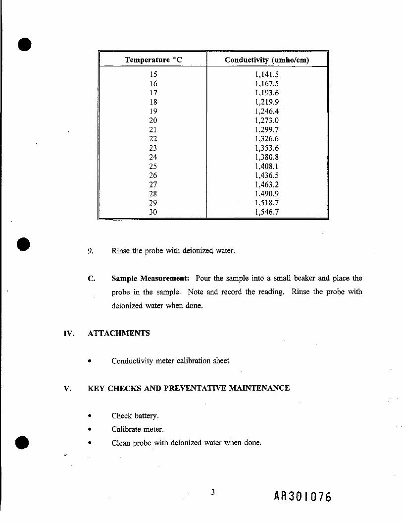
Temperature °C
15161718192021222324252627282930
Conductivity (umho/cm)
1,141.51,167.51,193.61,219.91,246.41,273.01,299.71,326.61,353.61,380.81,408.11,436.51,463.21,490.91,518.71,546.7
9. Rinse the probe with deionized water.
C. Sample Measurement: Pour the sample into a small beaker and place the
probe in the sample. Note and record the reading. Rinse the probe with
deionized water when done.
IV. ATTACHMENTS
• Conductivity meter calibration sheet
V. KEY CHECKS AND PREVENTATIVE MAINTENANCE
• Check battery.
• Calibrate meter.• Clean probe with deionized water when done.
A R 3 0 I 0 7 6

• When reading results, note sensitivity settings.• Refer to operations manual for recommended maintenance.
• Check batteries, and have a replacement set on hand.
WDCR701/007.51
A R 3 0 I 0 7 7

CONDUCTIVITY METER CALIBRATION SHEET
Instrument Readings
Analyst Uncalibrated CalibratedDate Time Initials (a), EC=22S (a), EC=22S Comments
WDCR701/007.51
A R 3 0 I 0 7 8

SOP 12: Volatiles Monitoring
I. PURPOSE AND SCOPE
The purpose of this procedure is to provide guidelines for the calibration and use ofthe Century Model OVA-128 Organic Vapor Analyzer.
II. EQUIPMENT AND MATERIALS
• Operations manual• An OVA-128 hand readout unit and side pack assembly
• Ultra-pure H2 gas as fuel (99.999 percent pure)• 100 ppm methane as calibration gas
• T-type feeder tube with 1.5 1/min. regulator
III. PROCEDURES AND GUIDELINES
ONLY PROPERLY TRAINED PERSONNEL SHOULD USE THIS
INSTRUMENT. FOR SPECIFIC INSTRUCTIONS, SEE OPERATIONSMANUAL.
Century Model OVA-128 Organic Vapor Analyzer
1. Introduction
The Century Model OVA-128 Organic Vapor Analyzer is designed todetect organic materials in air. It uses a hydrogen flame ionization
detector (FID) as its detection principle. This detector allows themonitor to respond to a wide variety of organic compounds.
A R 3 0 I 0 7 9

2. Operational Checks
a. Connect the hand readout unit's electrical and pneumaticfittings to the side pack assembly.
b. Connect probe to the hand readout unit.
c. Place the "PUMP" switch in the ON position. Check thebattery's condition by placing the "INSTR" switch to theBATT position and observe the response on the hand readoutunit.
d. Place the "INSTR" switch in the ON position.
,that the "SAMPLE FLOW RATE" indicator shows flow.
f. Open the "H2 TANK VALVE" and the "H2 SUPPLYVALVE" one turn each. Allow fuel to flow for about1 minute.
g. Set calibration to XI0.
h. Press ignitor button and hold (no longer than 6 seconds) until
readout unit indicates ignition.
i. Use "CALIBRATE" knob to set readout to a reading of 0.
A R 3 0 I 0 8 0

3. Calibration
a. Assemble a calibration manifold as described in G.I.3 usingmethane as the calibration gas.
b. Set the "CALIBRATION SWITCH" to the appropriate
position for the concentration of the calibration gas. (UsuallyX10.)
c. Set the span to read 3.0.
d. Connect the instrument's probe to the calibration manifold andallow it to sample the calibration gas.
e. Adjust the span (3.0 ± 2.0) until the readout indicates close tothe concentration of the calibration gas. Check that the
reading is approximately the same for the XI00 scale.
f. Place the "CALIBRATION SWITCH" in the "XI" position,and adjust the meter to read 1 ppm so that a flame-out can be
observed before entering the site.
IV. ATTACHMENTS
• Calibration sheet
V. KEY CHECKS AND PREVENTATTVE MAINTENANCE
• Check battery.• Zero and calibrate.
A R 3 0 I 0 8 I

• Verify sensor probe is working.
• Recharge unit after use.
A complete preventative maintenance program is beyond the scope of this document.For specific instructions, refer to the operations manual.
• A complete spare instrument should be available whenever field operationsrequire volatiles monitoring.
• Spare parts should be on hand so minor repairs may be made in the field.
• Batteries should be charged daily.
• Occasionally allow the batteries to totally discharge before recharging tprevent battery memory from occurring.
WDCR701/008.51
A R 3 0 I 0 8 2

SOP 13: Explosimeter
I. PURPOSE AND SCOPE
The purpose of this procedure is to provide a guideline for field measurements of thelevels of combustible gas and oxygen in air.
II. EQUIPMENT AND MATERIALS
• Industrial Scientific (MX251) Combustible Gas and Oxygen Indicator, orequivalent meter, which can be field calibrated
• Flow-control regulator and hose
• Calibration gas (50 percent LEL pentane—0.75 percent pentane and
15 percent oxygen in nitrogen)
• Equipment calibration data sheet
IH. PROCEDURES AND GUIDELINES
A. 'Calibration: The explosimeter must be calibrated before initial daily use.Record calibration information on equipment calibration data sheet.Calibration will be performed according to the following procedure:
1. Turn instrument on• Unscrew knurled nut on bottom
• Rotate metal cover 180°• Tighten knurled nut
& R 3 0 I Q 8 3

2. Check battery• Check for no "LoBatt" display—do not use if LoBatt
displayed
3. Calibrate instrument
• Observe that instrument reads 0 percent LEL and 21 percentOxygen (OX) (record readings)
• Connect sampling pump onto top of instrument• Connect .75 percent Pentane/15 percent oxygen gas (with 1.5
LPM Regulator and direct tubing)• Turn pump ON
• Turn gas ON
• Record LEL and O2 after stabilized; LEL must read 50 percent+/-5 percent; O2 must read 15 percent +/- 5 percent ^^
1 > • Disconnect sample pump and return to charger ^^
B. Sample Measurement: The instrument is then ready for air sampling. Noteand record the readings for percent LEL and percent O2
IV. ATTACHMENTS
• Equipment calibration data sheet
V. KEY CHECKS AND PREVENTATIVE MAINTENANCE
Check that the batteries be adequately charged. Certain materials such as silicone,silicates, and organic lead compounds tend to poison the catalyst in the instrument,
thereby giving erroneously low readings; calibration checks should be madefrequently if such materials are suspected to be present.
A R 3 0 I 0 8 1 *

If the CGI does not cal-check within +5 percent of 50 percent LEL, an internalcalibration must be performed, or the instrument replaced.
WDCR701/009.51
A R 3 0 I 0 8 5

SOP 14: Water-Level Measurements
I. PURPOSE AND SCOPE
The purpose of this procedure is to provide a guideline for the measurement of the
depth to ground-water in monitoring wells, where a second phase of floating liquid(e.g., gasoline) is not encountered. This SOP includes guidelines for discrete
measurements of static water levels.
II. EQUIPMENT AND MATERIALS
A. Discrete Measurements of Static Water Level
• Electronic water level meter, Solinst or equivalent, with a minimum150-foot tape; cable should have graduations in increments of 0.1 feet
or less
• Engineering rule graduated in 0.01-foot increments
HI. PROCEDURES AND GUIDELINES
A. Measurement Of Static Water Level
Verify that the unit is turned on and functioning properly. Slowly lower the
probe on its cable into the well until the probe just contacts the watersurface; the unit will respond with a tone or light signal. Sight across the top
of the locking well casing adjacent to the measuring point, recording theposition of the cable when the probe is at the water surface. The measuringpoint will be a standardized surveyed location on the top of each well casing,
/ IR30I086

adjacent to the lock hasp, indicated by a notch, paint mark, or similarmethod. Measure the distance from this point to the next lower intervalmarker on the cable, and record the water level reading in the log book.
Measure and record the three following additional readings: (1) the depth ofthe well; (2) the depth from the top of the casing to the top of the well riser;and (3) the distance to the surface of the concrete pad or to ground.
Measurements are to be taken with respect to the measuring point on the topof the well casing. The depth of well may be measured using the water-levelprobe with the instrument turned off.
IV. ATTACHMENTS
None.
V. KEY CHECKS AND PREVENTATIVE MAINTENANCE
A. Discrete Measurements of Static Water Level
Prior to each use, verify that the battery is charged by pressing the test button
on the water-level meter. Verify that the unit is operating correctly bytesting the probe in distilled or deionized water. Leave the unit turned off
when not in use.
WDCR701/010.51
A R 3 0 I 0 8 7

SOP 15: Preserving Non-VOC Aqueous Samples
I. PURPOSE
To provide general guidelines for preserving aqueous samples.
II. SCOPE
Standard aqueous sample preservation procedures for non-VOC samples are provided.
III. EQUIPMENT AND MATERIALS
• Disposable eye droppers
• Clean beakers for transfer of small portions of chemical preservative
• pH paper strips (Range 0 to 14)
• Chemical preservatives, as appropriate
• Personal protection, as appropriate
• Clean out door or vented indoor area
IV. PROCEDURES AND GUIDELINES
1. Remove caps from sample containers to be chemically preserved in designated area.
Add appropriate amount of chemical preservative to opened container. To determine
48301088

the approximate amount of preservative which will be required, preserve a sample of
potable water and calculate the volume of preservative required.
2. After adding the appropriate preservatives to the sample containers, cap containerstightly. Invert sample container a few times to mix.
3. After preserving all the sample containers and mixing, open the container and checkthe pH of the sample by pouring out a small quantity of the sample to a cleanreceptacle and dipping a pH indicating strip into the sample. Add more preservativeto the sample to adjust the pH, if necessary repeating steps 1 and 2. When threetime the amount of preservtive used to preserve a sample of potable water has been
added, record the pH and notify the ARCS Sample Manager that the sample couldnot be preserved.
4. Wrap, package, and ice samples according to the CLP User's Guide.
V. ATTACHMENTS
None.
VI. KEY CHECK ITEMS
WDCR701/011.51
A R 3 0 I 0 8 9

SOP 15: Preserving Non-VOC Aqueous Samples
I. PURPOSE
To provide general guidelines for preserving aqueous samples.
n. SCOPE
Standard aqueous sample preservation procedures for non-VOC samples are provided.
m. EQUIPMENT AND MATERIALS
• Disposable eye droppers
• Clean beakers for transfer of small portions of chemical preservative
• pH paper strips (Range 0 to 14)
• Chemical preservatives, as appropriate
• Personal protection, as appropriate
• Clean out door or vented indoor area
IV. PROCEDURES AND GUIDELINES
1. Remove caps from sample containers to be chemically preserved in designatedarea. Add appropriate amount of chemical preservative to opened container.To determine the approximate amount of preservative which will be required,
A 8 3 Q I Q 9 0

preserve a sample of potable water and calculate the volume of preservativerequired.
2. After adding the appropriate preservatives to the sample containers, capcontainers tightly. Invert sample container a few times to mix.
3. After preserving all the sample containers and mixing, open the container andcheck the pH of the sample by pouring out a small quantity of the sample to aclean receptacle and dipping a pH indicating strip into the sample. Add morepreservative to the sample to adjust the pH, if necessary repeating steps 1 and 2.When three time the amount of preservtive used to preserve a sample ofpotable water has been added, record the pH and notify the ARCS SampleManager that the sample could not be preserved.
, s 4. Wrap, package, and ice samples according to the CLP User's Guide.
V. ATTACHMENTS
None.
VI. KEY CHECK ITEMS
WDCR701/011.51
A R 3 0 I 0 9 I

SOP 16: Field Rinse Blank Preparation
I. PURPOSE
To prepare a blank to determine adequacy of decon procedures and whetherany cross-contamination is occuring during sampling.
II. SCOPE
The general protocols for preparing the rinse blank is outlined. The actual
equipment to be rinsed will depend on the requirements of the specificsampling procedure.
III. EQUIPMENT AND MATERIALS
• Blank liquid (use HPLC grade water)
• Sample bottles as appropriate
• Gloves
' • Preservatives as appropriate
IV. PROCEDURES AND GUIDELINES
A. Decontaminate all sampling equipment that has come in contact with
sample according to SOP 6.
A H 3 Q I Q 9 2

B. For volatiles, follow SOP 17. To collect the sample, pour blankwater over one piece of equipment and into two 40-ml vials until
there is a positive meniscus and seal vials. Note the sample number
and associated piece of equipment in the field notebook.
For non-volatiles, one aliquot is to be used for equipment. Forexample, if a pan and trowel are used, place trowel in pan and pour
blank fluid in pan such that pan and trowel surfaces which contactedthe sample are contacted by the blank fluid. Pour blank fluid frompan into appropriate sample bottles.
Do not let the blank fluid come in contact with any equipment that
has not been decontaminated.
C. Document and ship samples in accordance with the proceduresother samples.
D. Collect next field sample.
V. ATTACHMENTS
None.
VI. KEY CHECKS AND ITEMS
• Wear gloves.• Do not use any non-decontaminated equipment to prepare blank.
• Use HPLC grade water.
WDCR701/012.51
A R 3 0 I 0 9 3

SOP 17: VOC Sampling—Water
I. PURPOSE
To provide general guidelines for sampling aqueous volatile organiccompounds.
II. SCOPE
Standard techniques for collecting representative samples are summarized.Site specific details are discussed in the FSP.
in, EQUIPMENT AND MATERIALS
• Sample vials• Hydrochloric acid (HC1) for preservation• pH meter or pH indicating paper• Surgical or latex gloves
IV. PROCEDURES AND GUIDELINES
1. Sample VOCs before sampling other analyte groups.
2. When sampling for VOCs, evaluate the area around the samplingpoint for possible sources of air contamination by VOCs. Products
that may give off VOCs and possibly contaminate a sample includeperfumes and cosmetics, skin applied pharmaceuticals, automotive
products (gasoline, starting fluid, windshield deicers, carburetor
& R 3 Q I 0 9 1 *

cleaners, etc.) and household paint products (paint strippers, thinners,
turpentine, etc.).
3. To check the amount of hydrochloric acid (HC1) that needs to be
added at each location, fill a test vial (40 ml) with the water to besampled, add one drop of hydrochloric acid (HC1), gently mix, and
check the pH. Repeat this cycle (if necessary) until you reach a pHof 2, counting the number of drops of HC1 required. DISCARD THETEST VIAL and add an equal number of drops of HC1 to each of thesample vials. Proceed to sample.
4. Keep the caps off the sample vials for as short a time as possible.
5. Wear clean gloves.
6. Fill the sample vial immediately, allowing the water stream to strike
the inner wall of the vial to minimize formation of air bubbles. DONOT RINSE THE SAMPLE VIALS BEFORE FILLING.
7. Fill the sample vial with a minimum of turbulence, until the waterforms a positive meniscus at the brim.
8. Replace the cap by gently setting it on the water meniscus. Tighten
firmly, but DO NOT OVERTIGHTEN.
9. Invert the vial and tap it lightly. If you see air bubbles in the sample,
do not add more sample. Use another vial to collect another sample.Repeat if necessary until you obtain a proper sample.
A R 3 0 I 0 9 5

10. Samples of some locations may react with HC1 to produce gasses. Ifthis occurs, the sample preservation should be attempted using the
additional preservatives identified in Table 5-2 of the QAPjP.
V. ATTACHMENTS
None.
VI. KEY CHECKS AND ITEMS
Check for possible sources of contamination.Check pH.
Fill slowly, with as little turbulence as possible.Check for air bubbles.
WDCR701/013.51

SOP 18: VOC Sampling—Solids
The proceedures covered in this SOP are included in SOP 4: Soil Sampling.
WDCR701/016.51
A R 3 0 I 0 9 7

SOP 19: Civil Surveying
I. SURVEYING: GENERAL
Modified third order survey procedures will be used for all surveying.
n. RECORDS
All field notes should be kept in bound books. Each book should have an index.Each page of field notes should be numbered and dated and should show theinitials of all crew members. The person talking field notes will be identified inthe log. Information on weather (wind speed/wind direction, cloud cover, etc.)and on other site conditions should also be entered in the notes. Notes shouldalso include instrument field I.D. number and environmental settings. Graphitepencils or waterproof ballpoint pens should be used. Erasing is not acceptable;
.use a single-strike-through and initial it. The notekeeping format shouldconform to the Handbook of Survey Notekeeping by William Pafford. A surveywork drawing with grid lines and at the scale of the topographic map should beprepared for all survey field work. (Field notebooks will be available on site.)
HI. TRAVERSE SURVEY
Horizontal angular measurements shall be made with a 20-second or bettertheodolite or transit. When using a 20-second instrument the horizontal anglesshall be turned 4 times, (2 each direct and inverted) with the mean of the fourthangle being within 5 seconds of the mean of the second angle. When using a 10second or better instrument the angles shall be doubled, (once each direct andinverted) with the mean of the second angle within 5 seconds of the first angle.Minimum length of any Traverse courses shall be 300 feet.
1 A R 3 0 I 0 9 8

Distance measurements shall be made with a calibrated steel tape corrected fo;temperature and tension or a calibrated electronic distance meter (EDM).When using a EDM the parts per million (PPM), curvature and refractioncorrections shall be made. Vertical angle measurements used for distance slopecorrections shall be recorded to the nearest 20 seconds of arc deviation from thehorizontal plane.
Horizontal traverse stations shall be established and referenced for future use.All stations shall be described in the field notes with sufficient detail to facilitatetheir recovery at a later date. The station shall consist of a permanent markscribed on facilities such as sidewalks, curbs, concrete slabs, or iron rod and cap.
Vertical Survey
When practical, vertical control will be referenced to the NationalVertical Datum (NGVD) of 1929, obtained from a permanent bench mark. Ifpractical, level circuits should close on a known bench mark other than thestarting bench mark. The following criteria shall be met in conducting thesurvey:
• Instruments shall be pegged weekly or after any time it is dropped orseverely jolted.
• Foresight and backsight distances shall be reasonably balanced and shallnot be greater than 250 feet in length.
• No side shot shall be used as a beginning or ending point in another levelloop.
A R 3 0 I 0 9 9

• Rod readings shall be made to 0.01 foot and estimated to 0.005 feet.
• Elevations shall be adjusted and recorded to 0.01 foot.
Temporary bench marks (TBMs) shall be established and referenced for futureuse. All TBMs shall be described in the field notes with sufficient detail tofacilitate their recovery at a later date. The TBMs shall consist of a permanentmark scribed on facilities such as sidewalks, curbs, concrete slabs, etc. or spikesset in the base of trees (not power poles), or tops of anchor bolts fortransmission line towers, etc. (Horizontal traverse stations will not beconsidered as a TBM, but may be used as a permanent turning point.)
Traverse Computations and Adjustments
Traverses will be closed and adjusted in the following manner:
• Step One—Coordinate closures will be computed using unadjustedbearings and unadjusted field distances.
• Step Two—Coordinate positions will be adjusted (if the traverse closeswithin the specified limits) using the compass rule.
• Step Three—Final adjusted coordinates will be labeled as "adjustedcoordinates." Field coordinates should be specifically identified as such.
• Step Four—The direction and length of the unadjusted error of closure,the ratio of error, and the method of adjustment shall be printed with thefinal adjusted coordinates.
A R 3 0 I 1 0 0

Level Circuit Computations and Adjustments
Level circuits will be closed and adjusted in the following manner:
• For a single circuit, elevations will be adjusted proportionally, providedthe raw closure is within the prescribed limits for the circuit.
• In a level net where the elevation of a point is established by more thanone circuit, the method of adjustment should consider the length of eachcircuit, the closure of each circuit, and the combined effect of all theseparate circuit closures on the total net adjustments.
Monitoring Well Surveys
Monitoring well locations will be surveyed only after the installation of the.casing, (with its tamper proof locking cover), which is set in concrete. Thehorizontal plane survey accuracy is +1 foot and is measured to any point on thewell casing cover. The vertical plane survey must be accurate to +0.01 foot.The following two elevations will be measured:
• Top of the outer protective casing (on the lip next to the lock hasp, notthe cap).
• Ground surface (on the north side of the well).
If no notch or mark exists, the point at which the elevation was measured on theinner casing, shall be described so that water level measurements may be takenfrom the same location. Wells will not be opened because of health and safetyconcerns.
A R 3 0 I 1 0 1

Grid Surveys
Selected soil boring locations may be located by the survey crew after the soilborings are complete. The selected borings will be staked in the field by thefield team leader. The stake will be marked with the boring number forreference. The horizontal plane survey accuracy is +_ 1 foot and is measured toany point on the ground surface immediately adjacent to the stake.
WDCR701/014.51

Exhibit ASTANDARDS FOR MODIFIED THIRD-ORDER PLANE SURVEYS
Traverse
Max Number of bearing coursesbetween azimuth checks
Astronomical bearings:standard error of results
Azimuth closure at azimuthcheckpoint not to exceed
Standard error of the meanfor length measurements
Position closure per loop infeet before azimuth adjustment
Leveling
Levels error of closure perloop in feet
30
6"
20" VN
1 in 50,000
1:10,000
0.05
N = the number of stations for carrying bearingM = the distance in miles
WDCR701/014.51
A B 3 0 I 1 0 3

SOP 20: Field Measurement of Dissolved Oxygen
I. PURPOSE
To provide general guidelines for the calibration and use of the Dissolved Oxygen (DO)meter.
II. SCOPE
This is a general guideline for the field" use of a DO meter. For specific instructions,refer to the operations manual.
III. EQUIPMENT AND MATERIALS
• Operations manual
• A DO probe and readout/control unit with batteries
• Electrolyte solution (KC1 dissolved in deionized water) and probe membrane
IV. PROCEDURES AND GUIDELINES
A. Calibration
Calibrate prior to initial daily use before any readings are taken. Clean probeaccording to manufacturer's recommendations.
1. Prepare DO probe according to manufacturer's recommended proceduresusing electrolyte solution.
2. In the off position, set the pointer to zero using the screw in the center ofthe meter panel.
1 A R 3 0 I I O I *

3. Turn function switch to red line and adjust using red line knob untilmeter needle aligns with red mark at the 31 degrees C position.
4. Turn function switch to zero and adjust to zero using the zero controlknob.
5. Attach prepared probe and adjust retaining ring finger tight.
6. Allow 1 5 minutes for optimum probe stabilization (when meter is off orduring disconnection of the probe).
7. Place probe in hollow stopper that is supplied for use with the YSICalibration Chamber.
8. Place approximately 1/2 inch of deionized water into a 4-ounce, widemouth screw cap bottle. Keep this bottle capped and with the DO metera
9. Just before use, shake the bottle to saturate the water with air.
10. Remove cap, place probe in bottle keeping an air-tight seal around therubber stopper. Swirl water around in the bottle while waiting forconditions to reach equilibrium.
1 1 . Shield chamber from sun and wind to avoid temperature fluctuations
during calibration.
12. Turn function switch to temperature and record temperature reading.Determine calibration factor for that temperature and altitude correction
factor from tau supplied by manufacturer.
13. Multiply the calibration factor by the correction factor to get a correctedcalibration value.
A R 3 0 1 1 0 5

14. Turn function switch to appropriate ppm range and adjust the calibrateknob until the meter reads the corrected calibration value. Wait twominutes to verify calibration value. Re-adjust as necessary.
B. . Procedure
1. Before going out into the field:
a) Check batteries
b) Obtain fresh electrolyte solution
c) Prepare DO probe
2. Calibrate meter using calibration procedure.
3. Place probe in water to be measured. The probe should be movedthrough the water at 1 ft/sec or use a probe with a built-in stirrer.
4. Allow sufficient time for probe to stabilize to water temperature and DO.Record DO meter reading.
V. ATTACHMENTS
None. .
VI. KEY CHECKS AND ITEMS
• Battery check• Calibration
A R 3 0 I 1 0 6

VII. PREVENTIVE MAINTENANCE
Refer to operation manual for recommended maintenance.Check batteries, have replacement set on hand.
WDCR701/015.51
f t R G O l 1 0 7

DO METERCALIBRATION SHEET
Analyst's Temp Alt. Predict ActualDate Time Signature (C) (ft} (ppm 0,) (ppm 0,) Comment
A R 3 0 I 1 0 8

SOP 21: Groundwater Sampling
I. PURPOSE AND SCOPE
This procedure presents guidelines for the collection of groundwater samples frommonitoring wells.
II. EQUIPMENT AND MATERIALS
• Bladder-type groundwater sampling pump; QED Well Wizard or equivalent
• Pump controller and power supply (if electrical)
• Air supply; internal or external compressor or bottled air
• Probe box; stainless steel box with inlet/outlet ports for purged groundwaterand watertight ports for each probe
• pH/Eh meter; Orion Model SA250 or equivalent
• Dissolved oxygen meter
• Temperature/conductivity meter; YSI Model 33 or equivalent
• In-line disposable 0.45p, filters; QED FF8100 or equivalent
• Bailer, stainless steel
A R - 3 0 1 109

• Peristaltic Pump with Tubing (capable of yielding 2 gpm)
• Purge Pump
III. PROCEDURES AND GUIDELINES
A. Setup and Purging
1. For the well to be sampled, information is obtained on well location,
diameter(s), depth, and screened interval(s), and the method fordisposal of purged water.
2. A pump will be used for well purging. The expected mechanisms isa surface pump with dedicated purge pipe for each well. Tjte
•N. bladder-type pumps will be used when contaminant distributBnpatterns suggest low levels of contamination.
3. Instruments are calibrated according to manufacturer's instructions.
4. The well number, site, date, and condition are recorded in the fieldlogbook.
5. Plastic sheeting is placed on the ground, and the well is unlocked andopened.
6. Water level measurements are collected in accordance with SOP 14,and the total depth of the well is measured.
A R 3 0 I I 1 0

7. The volume in gallons of water in the well casing or sections of
telescoping well casing is calculated as follows:
0.052 (n A) = 0.163 (A) = gallons
where: n = 3.14
r = Radius of the well pipe in inchesh = height of water in well in feet •
The volume of water in typical well casings may be calculated as
follows:
2-inch diameter well:
0.163 gal/ft x __ (linear feet of water ) = gallons
4-inch diameter well:0.653 gal/ft x __ (linear feet of water ) = gallons
6-inch diameter well:1.469 gal/ft x __ (linear feet of water ) = gallons
The initial field parameters of pH, Eh, dissolved oxygen, specific
conductance, and temperature of water are measured and recorded inthe field logbook. The measurement probes are inserted into theprobe box. The purged groundwater is directed throughout the box,
allowing measurements to be collected before the water contacts theatmosphere.
8. Sampling equipment is cleaned and decontaminated prior to samplingin accordance with SOP 6.
A R 3 Q I I i

9. If a bailer is being used, it is removed from either its protective
covering or the well casing and attached to a cord compatible withconstituents and long enough to reach the bottom of the well. If a
bladder pump is being used, air, sample, and lifting lines are attachedto the pump. The lifting lines should bear the weight of the pump;
the air and ? le lines are attached to the lifting lines at 10-footintervals. If the well is purged using dedicated tubing, it is loweredinto the well to the top of the screened zone.
10. The sampling device is lowered to the well interval from which the
sample is to be collected. If a bailer is being used, it is allowed tofill with a minimum of surface disturbance to prevent sample water
aeration. When the bailer is raised, the bailer cord must not touch theground.
For the bladder pump, the air lines from a regulated compressed gassource are connected to a control box, a power supply connected tothe pump, and air flow started and adjusted with the throttle knob on
the control box. Discharge and refill knobs on the control box areused to control the cycling rate of flow in the bladder. Equal lengthcycles are generally desirable, but individual well conditions should
be controlling.
11. During purging, the field parameters are measured at least onceduring each well volume.
In productive wells, the well purging end point is determined usingthe field measurements. In nonproductive wells, the well is
repeatedly bailed dry to obtain a minimum of three well volumes, Iallowed to recover before sampling.
A R 3 0 ! I 12

12. Three to five well volumes are purged (more may be purged if
parameters do not stabilize). Purging is stopped when fieldparameters have stabilized over two consecutive well volumes. Field
parameters are considered stabilized when pH measurements agreewithin 0.5 units, temperature measurements agree within 1°C, andspecific conductance measurements agree within 10 percent (e.g., 100
units for readings of 1,000 /^mhos/cm.
B. Sample Collection
Once purging has been completed, the well is ready to be sampled. The
elapsed time between completion of purging and collection of thegroundwater sample from the well should be minimized. Typically, the
sample is collected immediately after the well has been purged, but this isalso dependent on well recovery.
Samples will be placed in bottles that are appropriate to the respective
analysis and that have been cleaned to laboratory standards. Each bottletypically will have been previously prepared with the appropriatepreservative, if any.
The following information, at a minimum, will be recorded in the log book:
• Sample identification (site name, location, and project number;sample name/number and location; sample type and matrix;
time and date; sampler's identity)
• Sample source and source description
• Field observations and measurements (appearance, volatilescreening, field chemistry, sampling method), volume of water
A R 3 0 I I 13

purged prior to sampling, number of well volumes purged, and
field parameter measurements
• Sample disposition (preservatives added; laboratory sent to,
date and time sent; laboratory sample number, EPA TrafficReport or Special Analytical Services number, chain-of-
custody number, sample bottle lot number)
• Additional remarks
The steps to be followed for sample collection are as follows:
1. The cap is removed from the sample bottle, and the bottle is tiltedslightly.
2. The sample is slowly poured from the bailer or discharged from the
pump so that it runs down the inside of the sample bottle with aminimum of splashing. Samples may be field filtered before transfer
to the sample bottle. Filtration must occur in the field immediatelyi
upon collection. Inorganics, including metals, are to be collected andpreserved in the filtered form. The recommended method is through
the use of a disposable in-line filtration module (0.45 micron filter)using the pressure provided by the pumping device for its operation.
When a bailer is used, filtration may be driven by a peristaltic pump.
3. Samples collected for VOC analysis will be collected using a bailerwhen the well is purged using dedicated tubing and a surface pump.
4. Adequate space is left in the bottle to allow for expansion, excepiBirVOC vials, which are filled to overflowing and capped.
6 A R 3 0 I I U

5. The bottle is capped, then labeled clearly and carefully, in accordancewith Procedure No. 23.
6. Samples are placed in appropriate containers and, if necessary, packedwith ice in coolers as soon as practical.
7. If the sampler is dedicated, it is returned to the well and the well is
capped and locked. Nondedicated samplers are cleaned anddecontaminated in accordance with Procedure No. 6.
IV. ATTACHMENTS
None.
V. KEY CHECKS AND PREVENTATIVE MAINTENANCE
Maintain field equipment in accordance with the manufacturer's recommendations;this will include, but is not limited to:
• Inspect pump bladder regularly and replace as warranted
• Inspect tubing regularly and replace as warranted
• Inspect air/sample line quick-connects regularly and replace as warranted
• Verify battery charge, calibration, and proper working order of field
measurement equipment prior to initial mobilization and daily during field
efforts
WDCR701/018.51
A R 3 Q I I 15

SOP 22: Aquifer Testing
I. PURPOSE AND SCOPE
The purpose of this procedure is to outline the equipment and methods that will beused to perform variable-head tests ("slug" tests) on the new monitoring wells.
II. EQUIPMENT AND MATERIALS
Campbell Scientific, Inc., Model 2IX dataloggerDruck pressure transducers
Well testing assembly ("beast")packerfittings for pressure transducersfittings for air supplyrelease valve
Compressed airComputer and associated equipmentSolid displacement device with rope
lU. PROCEDURES AND GUIDELINES
The tests which will be preformed are rising head tests. The tests are accomplished
by lowering the head of water in the well, and monitoring the recovery of the waterlevel to the static water level. The water level will be lowered by one of two
methods. In most cases, an air displacement device will be used. An alternatemethod is the use of a solid displacement device removed from the well.
A R 3 0 I I 16

The air displacement apparatus consists, of a packer assembly, fittings to
accommodate transducers and air pressurization, and a pressure-release valve. Thepacker is lowered into the ur::er portion of the monitoring well, secured in place andinflated, providing a seal between the apparatus and the inside of the well. Two
fittings are provided for pressure transducers; one transducer is fed through theinside of the device and positioned below the water surface, and the other is inserted
to measure the air pressure inside the assembly. A third fitting is connected to thepressurized air supply, a compressed air tank.
The datalogger will be programmed to display the air pressure in units of head, thehead measured by the submerged transducer, and the difference between the two.
The difference between the two pressure transducers is the height of the watercolumn on the submerged transducer. These readings are recorded hi a field
notebook, and then the assembly is pressurized. The air pressure applied will^equivalent to 3 to 7 feet of head. The pressures are allowed to stabilize,
pressure of the air should not lower the water level to below the base of thebentonite seal installed in the well.
11J*
TTC
Each test is started by releasing the air pressure inside the assembly and allowing thewater level to rise to the static water level. When the datalogger perceives a change
in water level in the well above a preset trigger amount, it automatically begins to
record the water levels and elapsed time. Each test will be terminated when thewater level has recovered to at least 90 percent of the original equilibrium levelbefore pressurization.
At some wells, it may be necessary to use an alternate method of lowering the water
level because the well is screened across or near the water table. A single transducerwill be installed in the well below the water table. A weighted solid displacement
device is added to the well and the water level allowed to stabilize at the ostatic water level.
A R 3 0 I I 1 7

SOP 23: Region III Sample Paperwork
A.R30I I 18

EPA Sample Paperwork November 2, 1992
The following pages contain information that was designed to assist you in completing theEPA Sample Paperwork correctly. In order for these checklists to be effective you needtraining on how to fill out the paperwork by the sample manager. Without the training,these checklists will not be as effective.
The intent of these checklists is to make you think about what you are doing. It isextremely easy to make a simple error, and following the checklists will help eliminatethose errors.
You will notice as you read through the beginning pages that we talk about a lot of pre-sampling preparation of the paperwork: we strongly recommend you do this. It makes thesampling event go much smoother and you are not so pressed for time at the end of the day.
During the sampling event there are a few things you should keep in mind:
• Always follow the Sampling and Analysis Plan (SAP). The SAP is the Biblefor all sampling events and its procedures should be followed as they aredescribed.
• QC samples: make sure all of the QC requirements listed in the SAP arecovered.
• Never call SMO with any questions at all. We are not allowed to talk tothem unless we are giving them shipping information.
• Send copies of the completed paperwork to the Sample Manager (DavidClark/WDC) every night you ship samples (by Federal Express or FAX).CRL and SMO often have questions and we need to be able to look at thepaperwork to answer these questions.
• PLEASE CALL IN THE EVENT YOU ARE UNSURE ABOUTANYTHING!! WE ARE HERE TO HELP.• Sample Manager - David Clark/WDC (x4305)• Site Manager - Site Specific• Secondary Sample Manager - Koumudi Ketkar/WDC (x4238)
A R 3 0 I I 1 9
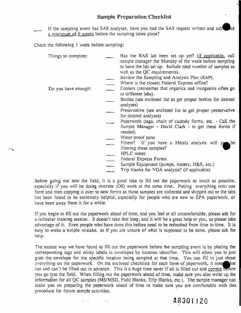
Sample Preparation Checklist
__ If the sampling event has SAS analyses, have you had the SAS request written and summeda minimum of 6 weeks before the sampling takes place?
Check the following 1 week before sampling:
Things to complete: __ Has the RAS lab been set up yet? (if applicable, callsample manager the Monday of the week before samplingto have the lab set up. Include total number of samples aswell as the QC requirements).
__ Review the Sampling and Analysis Plan (SAP).__ Where is the closest Federal Express office?
Do you have enough: __ Coolers (remember that organics and inorganics often goto different labs).
__ Bottles (see enclosed list to get proper bottles for desiredanalyses)
__ Preservative (see enclosed list to get proper preservativefor desired analyses)
__ Paperwork (tags, chain of custody forms, etc. - Call theSample Manager - David Clark - to get these forms ifneeded)
__ Water-proof pens__ Filters? If you have a Metals analysis will
filtering these samples?__ HPLC water__ Federal Express Forms__ Sample Equipment (pumps, meters, H&S, etc.)__ Trip blanks for VOA analysis? (if applicable)
Before going out into the field, it is a good idea to fill out the paperwork as much as possible,especially if you will be doing oversite (OS.) work at the same time. Putting everything onto oneform and then copying it over to new forms as those samples are collected and shipped out to the labshas been found to be extremely helpful, especially for people who are new to EPA paperwork, orhave been away from it for a while.
If you begin to fill out the paperwork ahead of time, and you feel at all uncomfortable, please ask fora refresher training session. It doesn't take that long, and it will be a great help to you, so please takeadvantage of it. Even people who have done this before need to be refreshed from time to time. It iseasy to make a simple mistake, so if you are unsure of what is supposed to be done, please ask forhelp.
The easiest way we have found to fill out the paperwork before the sampling event is by placing thecorresponding tags and sticky labels in envelopes by location identifier. This will allow you to justgrab the envelope for the specific location being sampled at that time. You can fill in just abouteverything on the paperwork. On the enclosed checklists for each form of paperwork, itcan and can't be filled out in advance. This is a huge time saver if all is filled out andyou go into the field. When filling out the paperwork ahead of time, make sure you also write up theinformation for all QC samples (MS/MSD, Field Blanks, Trip Blanks, etc.). The sample manager canassist you on preparing the paperwork ahead of time to make sure you are comfortable with thisprocedure for future sample activities.
A R 3 0 I 1 2 0

Frequent Paperwork ProblemsThings To Avoid Doing
• Dissolved Metals analysis didn't get a separate CLP sample number from that of theTotal Metals.
Whenever you take a total and dissolved metals sample, they MUST get separate CLPSample Numbers. If they don't you will be writing a memo-to-file soon there after.
• Sampler didn't call SMO with shipping information or didn't call SMO before 3:00pmon Friday for Saturday deliveries.
Every night samples are shipped we need to call SMO with the shipping information.SMO needs to know about Saturday deliveries before 3:00pm so they can make suresomeone is at the lab to receive the samples.
• Tags incorrectly noted on the Chain of Custody form.
You need to be very careful when writing down these numbers. It is easy to transposenumbers or place them in the wrong box. This is a much to common problem thatneeds to be reversed, and that will be done only by being careful.
• MS/MSD samples not given the same CLP sample number.
When ever you collect a sample and an MS/MSD, all volumes need to get the sameCLP sample number. Example: You collect the sample, the MS and the MSD, this istriple the volume of normal. You will assign the same CLP sample number to all 3sets of samples. The reason, they are not separate samples, they are one in the samefor the lab to be able to perform QC on them.
• Sample description for trip blanks and field blanks not noted as LEACHATES,equipment blanks not noted as RINSATES.
EPA protocol calls for us to assign the description (Box 7 for the Organic andInorganic paperwork, Box 6 for the SAS paperwork) for the Trip Blanks and FieldBlanks as Leachates, while Equipment Blanks are called Rinsates.
A H 3 0 I 1 2 !

Sample Paperwork ChecklistInorganic Traffic Report/Chain of Custody
Fill out forms with available information:
B __ Case No. (RAS No.)A __ Project Code (W.A. No.), Account Code. (You can get these from the sample
. manager, David Clark/WDC)A __ Region No. (Ill), Sampling Co. (CH2M HILL), Sampler Name and SignatureC __ Date Shipped, Carrier (Fed Ex), Airbill No.A __ Site Name, City, State, Site Spill ID (last 2 digits of account code)A __ Type of Activity (We will fill in: Lead: SF=Superfund or PRP Remedial: RIFS,
RD, etc. depending on the site)B __ Lab Shipped to Address and "Attention-Sample Custodian" - no phone number in this
box.A __ CLP Sample No. (sticky labels) from bottles. Make sure you use the Inorganic Traffic
Report (ITR) labels. Note that filtered and unfiltered samples get separate CLP samplenumbers. Also put a "*" next to the filtered sample.
A __ A. Sample Description (from box 7) - Note that Trip Blanks and Field Blanks areLEACHATES and Equipment Blanks are RINSATES
A __ B. Concentration ("low" is the majority of our sampling concentrations, refer to the siteSAP for special procedures in the event of medium and high concentration samples)
A __ C. Sample Type (composite or grab-fill in the one being used)A __ D. Preservative (from box 6) - See attached table for analyses and preservative
requirements.A __ E. RAS Analysis - "X" the proper box for the desired analysisA __ F. Tag No. on Forms (can use a range if more than 1 tag is being used, provided the
tags run consecutively. Example: 3-1263634 - 36)A _;_ G. Station Location (this is CH2M HILL's designated sample location identifier.
Example: GW-2, GW-2DUP)C __ H. Date and Time of Sample CollectionA __ I. Sampler InitialsA __ J. Corresponding CLP organic Sample No. (if we have organic sampling at same
location, put in the organic CLP sample no.)A __ K. Designated Field QC on Forms: Blanks "B"(field/trip/etc.)
Duplicate "D"Not a QC Sample "-"
C __ Shipment for Case Complete? (If more sampling under this case, NO - if samplingtotally complete, YES)
C __ Page 1 of _?A __ Sample Used for Spike and/or Duplicate (when we have an MS/MSD we must put in
the CLP Sample No. of that sample in this box. This box should only be used forMS/MSD's, NOT field duplicates.)
C __ Additional Sampler Signatures (Just another place for more samplers to sign)C __ Chain of Custody Seal Number (We don't have seal numbers in Region III, what we
will use this box for is the filtered metals. When we do filter metals put the stateiMnt"* DIGESTION REQUIRED" in this box. If not filtered just write in "N/A" ^
C ___ Relinquished Signature, Date and Time
A = Can be filled out before the sampling event.B = If the lab assignment comes through from CRL early you will be able to fill this in before thesampling event.C = Will be filled out in the field during the sampling event. A R 3 0 I 122

l-fljooi
A R 3 0 I 1 2 3
g
IYRE
CO
u
1TOU
SZ
!
|J1•|oc
iF
aO
I
i>JO
«1I
1«..
13|
1P^ •1
^W
Relin
quish
ed b
y:
1
ja
1
IT
1F
1O
IOJ
f|I
|«?..
f5tt
iF
1
"3*w
s«
Relin
quish
ed b
y:
—
I|e .
1CO
Q3
|£
iF
1
ff
f|^
||g £C^
1" ^ ^
8
"3*
s«!JO
•?2
i1 if 1DD
(0
SA
1 ?i ?i i^ Ii -?I 2i I
1 28
t 1i. •_ •1 Iin £i ^• O5 a
K m** i
1 I
5 xae a
EPA
Form
111
0-1
(1D
ISTR
IBU
TIO
N:
Qi*»
n -
Reg
ion
Co
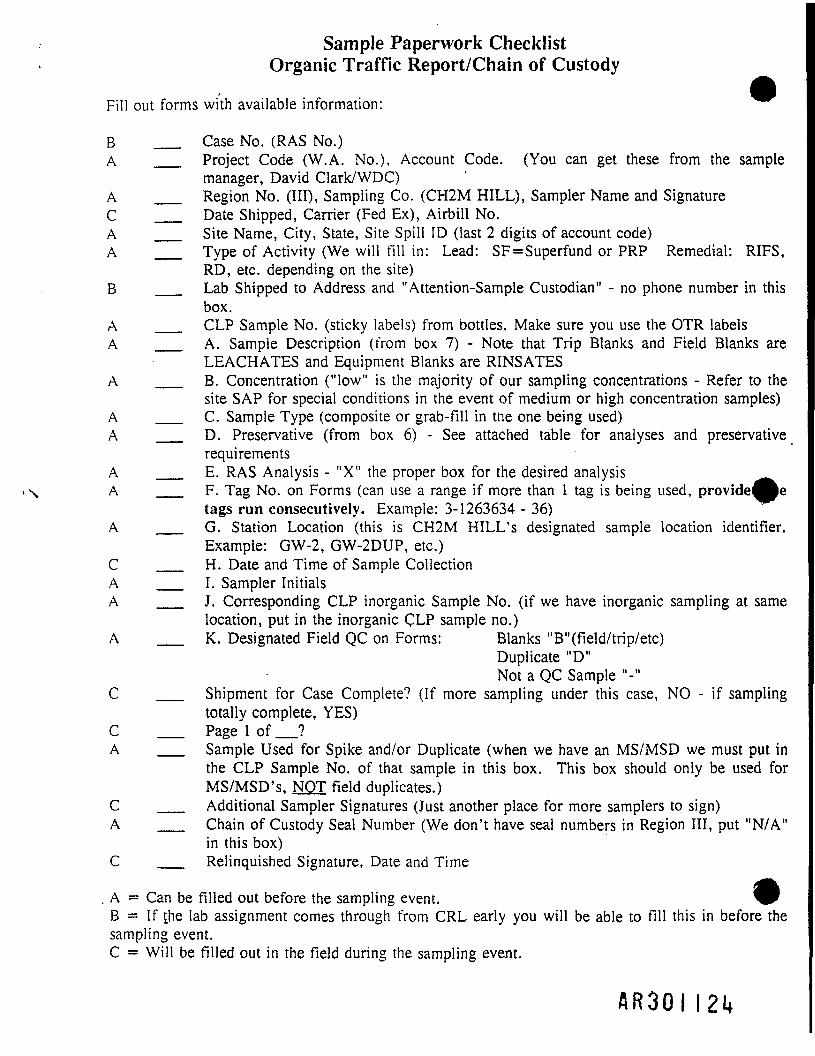
Sample Paperwork ChecklistOrganic Traffic Report/Chain of Custody
Fill out forms with available information:
B __ Case No. (RAS No.)A __ Project Code (W.A. No.), Account Code. (You can get these from the sample
manager, David Clark/WDC)A __ Region No. (Ill), Sampling Co. (CH2M HILL), Sampler Name and SignatureC __ Date Shipped, Carrier (Fed Ex), Airbill No.A __ Site Name, City, State, Site Spill ID (last 2 digits of account code)A __ Type of Activity (We will fill in: Lead: SF=Superfund or PRP Remedial: RIFS,
RD, etc. depending on the site)B __ Lab Shipped to Address and "Attention-Sample Custodian" - no phone number in this
box.A __ CLP Sample No. (sticky labels) from bottles. Make sure you use the OTR labelsA __ A. Sample Description (from box 7) - Note that Trip Blanks and Field Blanks are
LEACHATES and Equipment Blanks are RINSATESA __ B. Concentration ("low" is the majority of our sampling concentrations - Refer to the
site SAP for special conditions in the event of medium or high concentration samples)A __ C. Sample Type (composite or grab-fill in tne one being used)A __ D. Preservative (from box 6) - See attached table for analyses and preservative
requirementsA __ E. RAS Analysis - "X" the proper box for the desired analysis ^^A __ F. Tag No. on Forms (can use a range if more than 1 tag is being used, providefl^e
tags run consecutively. Example: 3-1263634 - 36)A __ G. Station Location (this is CH2M HILL's designated sample location identifier.
Example: GW-2, GW-2DUP, etc.)C __ H. Date and Time of Sample CollectionA __ I. Sampler InitialsA __ J. Corresponding CLP inorganic Sample No. (if we have inorganic sampling at same
location, put in the inorganic CLP sample no.)A __ K. Designated Field QC on Forms: Blanks "B"(field/trip/etc)
Duplicate "D"Not a QC Sample "-"
C __ Shipment for Case Complete? (If more sampling under this case, NO - if samplingtotally complete, YES)
C __ Page 1 of _?A __ Sample Used for Spike and/or Duplicate (when we have an MS/MSD we must put in
the CLP Sample No. of that sample in this box. This box should only be used forMS/MSD's, NOT field duplicates.)
C __ Additional Sampler Signatures (Just another place for more samplers to sign)A __ Chain of Custody Seal Number (We don't have seal numbers in Region III, put "N/A"
in this box)C __ Relinquished Signature, Date and Time
_B = If the lab assignment comes through from CRL early you will be able to fill this in before thesampling event.C = Will be filled out in the field during the sampling event.
A R 3 0 I 121*

-v 5 5 e -~ 'c ^ || § »^0 S &3<D S^TCOJn^1
'= E a>-oi52i< ~"Q» 9-. 3 y =-= tocoS S •- *fillc/5 Q -— — ^cjco'riricor^ajr~
j
j5.a.
^p^
__.
|-^ ^^
H
nnt'd
Sta
les
Lnvi
ronm
enid
i r-iu
iecn
uiiM
yt.-.
!..,
^. o
^..
.- ^
^^
fcJV
h H
A C
o""acl l '{J
o'aW
kSaS
na* v
AM2S3?
renl O
l"cu &
Cha
in o
f C
usto
dy R
ecor
d^^
^ 1—
1 /
\
7035
5/24
90
FTS
557
2490
(F
or O
rgan
ic C
LP A
naly
sis)
llil olflolS^o IIZIIf
^ — oi<*i j-ui(D
1 iso
4 D
ate
Ship
ped
Airb
ill N
umbe
r
i
60o>
1 !reco "5-
I it
if !iH !i;ca :c^>
Acc
ount
Cod
e
- --
i
t P
roje
ct C
ode
tR
egio
nal I
nfor
mat
ior
£Q.
COui
?>•® O _
§Si(OZ
pres
erve
d
ir 1
= 52S,|-_iaim=cnOCCCCOD
Sam
pler S
igna
ture
Non
-Sup
erfu
nd P
rogr
am
1
<?£^'Z*$£
Kln. *
syQ<«OQ-CCCCOZ
|
^ C£58CO
1>. Q. Q
i— u-OCl— IUri COQ.COU-
1
i11
ii
1l
o>
' 10
i a:K
a
Ia
CO
S2
*o
KDe
signa
ted
Field
OC
• d>6li2->£-£d.50. £"d30> inQ.IO
"HC0~
>>1(0 i™xQto «2I
i1
I
i1
1
1 1iiiii
1
1".Iits(0 =
'"S
§i|03 f|w3i
FR
egion
al S
pecif
icE
RAS
Anal
ysis
s
ilJ»Zif.cg> S?S
S?^tD<aficeOQ.Q-
<CD
i»_<£>
° 2^ SJ?i >— <n0) -~i
o||HZ&S*
.1, rffi 0o-$"S31§
S £^< c * o guj — (S
<» !2 _
-tillOa|£s
!
—— ""T
1
i1li
>
'
!
Chain
of C
usto
dy S
eal N
umbe
r
V)
£isw0)Q.
<n•«o•s
1
jr du
plica
te
1'1-(0
SiCO
A
1
to
'oo
6?
Ship
men
t for
Cas
eco
mpl
ete?
( Y/
N)
A R 3 0 I 125
1-6*0i
g
8!Q
2(03UU.Oz<5
"S"s<0
iCO.
>.S3
1U
5(0
F*». — — —SmQ
I
.1
52.
£•o0>_>
(X
Fa>roQ
i
Ii.§>52.
^•o0>£OT
11
"5"
152.
^•oO
"1uV
CC
f.Po5 ra
_Im§>&..IS"i-o*
"S"
<5
i£•§to
"3CC
fI52.>.a
1'5u3)t£
1P«'SO
1ICO.
'>.£>
?'j: ^ii if
'f 1?: a ' <D'EC 'ft
i2
?
S3
110ftoS<n
a>jt
or
iF- .-
i~•.'^
* *"-'•
* *'.>^f9At»_1
S-s
iliv.
. • -\v»
luOH
F ~Q.-,.., — .
; .
I1t°>.a•qo>1.2.VI*
DC
f13.
i pA
ccej
npd
( |
Dec
lined
••
tiff1
f
"*
£' '•fi-
I2>t
if
• u1.il-HI-.o" £
"1':•§CM
-r *e
i1> &r »
8
*»•o>4>•oeN
o z^ s
s i£ 5— t-2 SLU C

Sample Paperwork Checklist - SAS Packing List/Chain of Custody
Fill out forms with available information:
B __ SAS No.A __ Project Code (W.A. 'No.), Account Code. (You can get these from the sample
manager, David ClarkAVDC)A __ Region No. (Ill), Sampling Co. (CH2M HILL), Sampler Name and SignatureC __ Date Shipped, Carrier (Fed Ex), Airbill No.A __ Site Name, City, State, Site Spill ID (last 2 digits of the account code)A __ Type of Activity (We will fill in: Lead: SF=Superfund or PRP Remedial: RIFS,
RD, etc. depending on the site)B __ Lab Shipped to Address and "Attention-Sample Custodian" - no phone number in this
boxA __ Sample Numbers (SAS numbers on sticky labels). Make sure you use the SAS labels.A __ A. Matrix (from box 6) - Note that Trip Blanks and Field Blanks are LEACHATES
and Equipment Blanks are RINSATESA __ B. Concentration ("low" is the majority of our sample concentrations - Refer to the site
SAP for special conditions in the event of medium or high concentration samples)A __ C. Preservative (from box 7) - See attached list for analyses and preservative
requirementsA __ D. Analysis (write out the name. Example: SULFIDE)A __ E. Tag No. on Forms (can use a range if more than 1 tag is being used, provided the
tags run consecutively. Example: 3-1263634 - 36)A __ F. Station Location Identifier (this is CH2M HILL's designated sample station loca
Example: GW-2, GW-2DUP, etc.)C __ G. Date and Time of Sample CollectionA __ H. Sampler InitialsA __ I. Designated Field QC on Forms: Blanks "B"(field/trip/etc)
Duplicate "D"Not a QC Sample "-"
C __ Shipment for SAS Complete? (If more sampling under this case, NO - if samplingtotally complete, YES)
C __ Page 1 of _?A __ Sample Used for Spike and/or Duplicate (when we have a MS/MSD we must put in the
CLP sample number of that sample in this box. This box should only be used forMS/MSD's, NOT field duplicates.)
C __ Additional Sampler Signatures (Just another place for more samplers to sign)A __ Chain of Custody Seal Number (We don't have seal numbers in Region III, put "N/A"
in this box) •C __ Relinquished Signature, Date and Time
A = Can be filled out before the sampling event.B = If the lab assignment comes through from CRL early you will be able to fill this in before thesampling event.C = Will be filled out in the field during the sampling event.
^S^^
R R 3 0 1 1 2 6

R B 3 0 I I 2 7

Sample Paperwork Checklist - Sample Tags
These can be filled out before the sampling event takes place. Fill in everything but the da; ndtime, but just remember to fill these two things in before shipping off the samples.
__ Project Code (W,A. Number)__ Station Location (This is the CLP Sample Number from the sticky labels)__ Date of Sample Collection__ Time of Sample Collection__ Sample Type (Composite/Grab, "X" the proper box for the sample type)__ Station Location (this is CH2M HILL'S designated sample location identifier)__ Sampler Signature__ Preservative ("X" yes or no)__ Analyses (put :•; 'X" in the proper box of the analyses to be performed or write
in the analyses name in the last box if not on the list)__ Remarks (put ^e RAS or SAS Case Number and the preservative name here.
Example: HN^3, HC1, etc.) Also, if the sample is filtered note it in this box.
A 8 3 0 I I 2 8

GPO 706-155
1 D
esig
nate
I
am<5
1o0
£
Mon
lh/O
ay/Y
e*i
o
1
55
1Pr
ojec
t Cod
a
(ft0)3mcOitrtV)
O"5.<«w
1«L>O^Coc55
PreservativeYes n NO a
ANALYSES
BOD AnionsSolidS (TSS) <TDS) (SS)
COD, TOC, NutrientsPhenoticsMercuryMetalsCyanideOil and GreaseOrganics GC/MSPriority PollutantsVolatile OrganicsPesticidesMutagenicityBacteriology
Remarks:
_ TaoNo. Lati Sample No.3-I&63650
A R 3 0 I 1 2 9

Sample Paperwork Checklist - Shipping Logs
These are filled out after you have returned to the office after the sampling event is totally compleEach RAS or SAS Case Number needs to have a separate shipping log created.
__ Page 1 of___ Project Site Name•__ EPA Project Officer (RPM)__ RAS No. or SAS No.__ Project Site Leader (Site Manager)__ Site Sample Coordinator (David Clark)__ Phone Numbers for above individuals__ SAS Request Details - if applicable
• Write analyses type (Example: SULFIDE)• Preservation - Write in name of the one used (Example: HN03,
HC1, etc.) or a "-" if none.• If this is a RAS shipping log, put a large "X" in this box.
__ QC Sample Information (In this column denote all QC information. Example:Duplicate, Field Blank. Trip Blank, MS/MSD)
__ Concentration__ Sample Phase (GW, SW, Soil, Sludge, Sediment)__ Type of Request (ORG=Organic, INOR=Inorganic, or SAS)__ EPA Sample No. (CLP Sample Numbers from sticky labels)
RAS: A__ Lab Name (Most labs have abbreviations. If you don't have it ask the samprc
manager, David Clark/WDC)__ Date Shipped (not the date sampled, date shipped)__ Data Received ("X" out items NOT requested)__ Put a large "X" through the SAS columns
SAS:__ Lab Name (Most labs have abbreviations. If you don't have it ask the sample
manager, David Clark/WDC)__ SAS Request Itemized (Write in "Sec (10)"; This refers to the above section
where it gives the analyses and preservative)__ Date Shipped (not the date sampled, date shipped)__ Put a large "X" through the RAS columns
Nothing is filled in for Data Received. This is for CRL.Final Sampling (Located at the bottom of the page. Most likely will be "yes"since shipping logs will be filled out after the sampling event)Final Shipping Date
A R 3 0 I 1 3 0
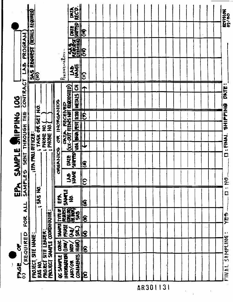
AB»
PR
06
sa:2^°8
UI
tl2IH
mm
t
iicIGt
8«_-.UI*I
S^5
-CL«^Itil ^
^
tf
RED
QIUtt
1J -
S
§II $
£A R 3 0 I 1 3 1

Sample Paperwork Checklist - Miscellaneous
__ If the shipment of samples is delayed or canceled, call the sampleDavid Clark/WDC at 703/471-6405 (ext. 4305). Please give a reason for thedelay/cancellation. CRL always needs a reason for delays/cancellations.
__ Did you double check SAS/RAS Numbers on the tags, labels and forms?__ Did you write out complete sample numbers on each tag? Did you use
preprinted sticky labels?__ Did you assign the same CLP Sample No. to all volumes of any MS/MSDs?__ Did you check tags, bottles, and forms for matching times and dates of sample
collection?__ Did you neatly cross-out any changes with one line, initial and date the change?
WRITE-OUT IS PROHIBITED!__ Did you put the airbill number on the chain of custody forms?__ Are the lab copies of the forms, the last 2 sheets of the paperwork, protected in
. the cooler, taped to the cooler lid? The sample shipping log does not go in thecooler.
__ Is the ice packed in plastic bags to minimize leakage during shipping?__ Are the tags securely attached to each sample bottle?__ Is each container sealed in a plastic bag (when appropriate)?__ Did you sign the "Relinquished by" box and fill in the date and time boxes?__ Are the chain-of-custody seals taped on cooler and secured with clear tape over
them to prevent accidental breakage of the seals?__ Is the CH2M HILL return address written on the front outside corner
cooler? If not, write it on there so the cooler will make its way back toHILL.
__ Did you write "Attention-Sample Custodian" on the Lab Address?__ Are all samples being shipped PRIORITY OVERNIGHT? - No GSA airbills,
use CH2M HILL airbills (bulk volume discount). Reason, GSA not guaranteedto get there in the AM the following day.
__ If Saturday delivery is required, the Federal Express form MUST be checkedfor Saturday delivery.
* Do not call labs or send them the sample shipping log__ Call EPA Sample Management Office (SMO) with complete sample
information. Many times you will reach an answering machine, you may leavethe complete shipping information in a message. This is the only thing we talkto SMO about. All other questions should go to the sample manager, DavidClark/WDC:
SAS Samples: Heather Kaese 703/519-1413RAS Samples: Jane von Hofen 703/519-1353
See the next page for the shipping information we are required to inform SMO about.
A R 3 0 I 1 3 2

Sample Paperwork Checklist - Miscellaneous Continued
Information Needed:• Your Name• Sample Company (CH2M HILL)• Region (III)• Contact Phone Number (your office)• Case/SAS Number• Date Shipped• Number of samples by concentration and matrix• Carrier (Fed Ex) and Airbill Number• Next planned shipment• Friday shipments for Saturday delivery MUST be
called in to SMO by 3:00pm.• CRL does not accept shipments on Saturday unless
authorized in advanced.
Things to do back at the office after the sampling event:__ Check over your paperwork to look for errors. It is better if CH2M HILL
discovers them and corrects them before EPA comments on them. If you dofind an error a memo-to-file needs to be written; this is discussed later.
__ Fill out the shipping log. These forms need to be submitted before anyanalytical packages are received by CRL.
__ Mail "REGION" copy of paperwork to:
Annette LageEPA Central Regional Laboratory (CRL)839 Bestgate RoadAnnapolis, MD 21401
This will be the white, green, or blue form as indicated on the bottom ofthe forms. Include the sample shipping log to CRL. Make sure youkeep a copy of both the shipping log and chain of custody, and send acopy to the sample manager. David Clark/WDC for the site sample files.
__ Mail "SMO" copy of the paperwork to:RAS - Jane von HofenEPA Sample Management Office (SMO)P.O. Box 818Alexandria, VA 22313
SAS - Heather KaeseEPA Sample Management Office (SMO)P.O. Box 818Alexandria, VA 22313
This will be the yellow or pink form as indicated on the bottom of theforms. SMO DOES NOT get a coy of the shipping log.
A R 3 0 I 1 3 3

Sample Paperwork Checklist - Memo-to-File
In the event you have made a mistake and you are told you need to do a memo-to-file or youdiscovered an error that requires a memo-to-file, there are some requirements as to the content ofmemo. This memo needs to be written and submitted IMMEDIATELY. The following is a list ofthose items that are required to be in that memo so they will be able to easily identify that sampleactivity:
__ Case(RAS)/SAS Number__ Overnight Carrier/Airbill Number__ Date of Shipment__ Chain-of-Custody Document Number__ Sample Numbers__ Tag Numbers__ Sampling Dates__ Analysis__ Correction of the Error__ Your Signature
* DON'T PUT THE SITE NAME IN THE MEMO-TO-FILE UNLESS THELAB WAS CRL.
Once all this is included in the memo-to-file it needs to be distributed to certain individuals:
__ Custodian of Samples at the Laboratory (they get the original signed copy)__ EPA RPM for the specific site__ Annette Lage/RSCC/CRL__ SMO RAS or SAS Coordinator (depending on lab assignment)
SAS: Heather Kaese RAS: Jane von Hofen__ CH2M HILL'S Sample Manager, David Clark/WDC (for the site sample files)
A.R30 I

BOTTLE TYPE, PRESERVATIVE AND HOLDING TIMES BY ANALYSIS
AqueousAnalysis Bottle Type Preservative Holding Time
Alkalinity 1 liter poly None 14 days
BNA/Semivolatiles 80oz amber None 7 days
Bromide (Br) 1 liter poly None 28 days
Chemical Oxygen Demand (COD) 1 liter poly H2SQ4 pH<2 28 days
Color 1 liter poly None 48 hours
Dissolved Organic Carbon (DOC) 1 liter poly H2SO4 pH<2 28 days
Fluoride (F) 1 liter poly None 28 days
Hexavalent Chromium (Cr+6) 1 liter poly None 24 hours
Metals 1 liter poly HNO3 pH<2 6 months preserved
Nitrite (N02) 1 liter poly None 48 hours
Oil and Grease (O&G) 1 liter poly H2SO4 pH<2 28 days
Phenol 1 liter poly H2S04 pH<2 28 days
Silica (Si) 1 liter poly None 28 days
Suifide 1 liter poly None 7 days
Total Dissolved Solid (TDS) 1 liter poly None 7 days
Total Organic Carbon (TOG) 1 liter poly H2SO4 pH<2 28 days
Total Solid (TS) 1 liter poly None 7 days
Turbidity 1 liter poly None 48 hours
HCL - Hydrochloric AcidNaOH - Sodium HydroxideHNO3 -Nitric Acid
H2SO4 - Sulfuric Acid*-•
This list does not contain all possible analyses or acceptable bottle types. It was compiled from atable in the "CRL Sample Submission Guidelines (9/18/90)." In the event a desired analysis is noton the list, call the sample manager to get the proper bottle type and preservative.
& R 3 0 1 I 35

BOTTLE TYPE, PRESERVATIVE AND HOLDING TIMES BY ANALYSIS
Soil/SedimentAnalysis Bottle Type Preservative Holding Time
Alkalinity N/A N/A N/A
BNA/Semivolatiles 8oz glass None 10 days
Bromide (Br) N/A N/A N/A
Chemical Oxygen Demand (COD) 8oz glass None 28 daysi-:?*^-:-'-1 •;I>>L'&::::I:^
Color N/A N/A N/A
Dissolved Organic Carbon (DOC) N/A N/A N/A
Fluoride (F) N/A N/A N/A
Hexavalent Chromium (Cr+6) N/A N/A N/A
Metals 8oz glass None 6 months preservedN/Ai
Nitrite (NO2) N/A N/A N/A
Oil and Grease (O&G) N/A N/A N/A
Phenol 8oz glass None 28 days
Silica (Si) N/A N/A N/A
Sulfide N/A N/A N/A—II
Total Dissolved Solid (TDS) N/A N/A N/A
Total Organic Carbon (TOG) N/A N/A N/A
Total Solid (TS) N/A N/A N/A
Turbidity N/A N/A N/A
This list does not contain all possible analyses or acceptable bottle types. It was compiled from atable in the "CRL Sample Submission Guidelines (9/18/90)." In the event a desired analysis is noton Jjie list, call the sample manager to get the proper bottle type and preservative.
A R 3 0 I J 3 6

SOP 24: ELECTROSHOCKER FISH SAMPLING
I. PURPOSE AND SCOPE
To provide a general guideline for conducting fish community surveys usingelectroshocking equipment.
H. EQUIPMENT AND MATERIALS
• Backpack electroshocker
• Boat-mounted electroshocker
• Seines
• Dip nets
• Personal protective equipment
• Measuring board
• Weighing equipment
• Coolers, ice, dry ice
• Water buckets
• Equipment operation manuals
• Gasoline
m. PROCEDURES AND GUIDELINES
1. Fish in the lagoon will be collected with a boat-mounted electrofishing unit.
2. Sample intervals will consist of approximately 30 minutes of shocking timeor until no new fish species are collected hi 10 minutes of shocking. Actualshocking time is to be recorded for each sample.
3. Fish will be collected with a long-handled dip net and placed in a live tankor bucket.
4. Information on species, size, location, and physical condition will berecorded for each fish captured. Any physical abnormalities will be noted.
WDCR708/035.51/Draft/04-30-93 1 A-R 3 0 I I 3 7

5. Select fish (target species) of the size that would be retained by fishermenwill be retained for tissue analysis. Target species of interest will be speciessuch as White Sucker or Carp. These species feed on invertebratesassociated with the bottom material, would most likely uptake contaminantsof concern, and could be utilized as a food resource by higher vertebrates,including man. Where possible, those specimens that are about the samesize (length and weight) will be retained.
6. Select fish (target species) will be retained for whole fish analysis. Thetarget species will be those that are bottom feeders which would most likelyuptake contaminants of concern, and could be used as a food resource byhigher vertebrates.
7. Sampling equipment, including the fish measuring board, will bedecontaminated according to the procedures outlined in SOP 6 betweensamples.
8. Information on habitat condition of the lagoon will be recorded, includingwater depth, substrate type, shoreline profile or vegetation and degree ofshading.
IV. ATTACHMENTS
None
V. KEY CHECKS
• Follow recommended safety precautions in operating the fish electroshockingequipment.
• Clean sample equipment between sample stations.
WDCR708/035.51/Draft/04-30-93 2 A R 3 fl I I 3 8

SOP 25: FISH SAMPLE COLLECTION PROCEDURES
I. PURPOSE AND SCOPE
To provide general guidelines on collecting, preserving, and shipping fish samplesfor chemical analysis. Fish samples will be collected using an electroshocker.Selected fish will be analyzed as whole fish or edible tissues for parameters ofinterest at the site.
H. EQUIPMENT AND MATERIALS
• Sample containers: teflon baggies, sample jars, aluminum foil
• Stainless steel knife
• Stainless steel tray, fillet board
• Personal protective equipment
• Coolers
• Dry ice
• Buckets
ffl. PROCEDURES AND GUIDELINES
After being collected, fish will be placed hi a live-well or equivalent until they canbe processed. Processing of fish includes identification, measuring weight andlength, and determining if they will be retained for analysis. Fish retained foranalysis will be killed by suffocation.
Fish will be collected for both whole fish and selected tissue analysis. Fish selectedfor selected^tissue analysis will be evaluated using Attachment 1 to determine if theskin should be removed. The fish will be filleted according to the procedureoutlined hi Attachment 2. Wastes generated during filleting will be disposed of aspotentially hazardous materials. Between each fillet, the sample handling equipmentwill be decontaminated according to SOP 6.
Samples for organics will be wrapped hi aluminum foil with the shiny side out.The aluminum foil will be taped shut using masking tape. The samples forinorganic analysis will be sealed in a teflon baggie. All of the samples will bestored and shipped to the analytical laboratories on dry ice.
WDCR708/035.51/Draft/04-29-93 3 A R 3 0 I I 3 9
IV. ATTACHMENTS
• Standard edible portions of fish.
• Fillet guidelines.
V. KEY CHECKS
• Decontaminate fillet equipment between samples.
• Samples should be stored on dry ice after they are killed.
WDCR708/035.51/Draft/04-29-93
A R 3 0 I
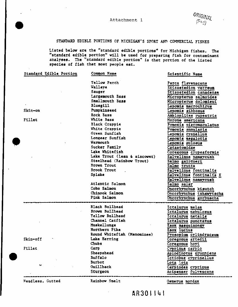
Attachment 1
STANDARD EDIBLE PORTIONS OF MICHIGAN'S SPORT ANP COMMERCIAL FISHES
Listed below are the "standard edible portions" for Michigan fishes. The"standard edible portion" will be used for preparing fish for contaminantanalyses. The "standard edible portion" is that portion of the listedspecies of fish that most people eat.
Standard Edible Portion
Skin-on
Fillet
Common Name
Yellow PerchWalleyeSaugerLargemouth BassSmallmouth BassBluegillPumpkinseedRoclc BassWhite BassBlack CrappieWhite CrappieGreen SunfishLongear SunfishWaraouthSucker FamilyLake WhitefishLake Trout (lean & siscowet)Steelhead (Rainbow Trout)Brown TroutBrook TroutSplake
Atlantic SalmonCoho SalmonChinook SalmonPink Salmon
Scientific Name
Perca flavenscensStizostedion vetreumStizostedion canadenseMicropterus salmoidesMicropterus dolomieuiLepomis macrochirusLepomis gibbosusAmbloplites rupestrisMorone americanaPomoxis nigromaculatusPcrmoxis annularisLapoais cyanellusLepomis megalotisLepomis gulosusCatastomidaeCoregonus cJupeaformisSalvelinus namaycushSalmo gairdneriSalmo truttaSalvelinus fontinalisSalvelinus fontinalis XSalvelinus namaycush ~~Salmo salarOncornynchus kisutchOncorhynchus tshavytschaOncorhynchus gorfauscha
Skin-off
Fillet
Black BullheadBrown BullheadYellow BullheadChannel CatfishMuskellungeNorthern PikeRound Whitefish (Menominee)Lake HerringChubsCarpSheepsheadBuffaloBurbotOuillbackSturgeon
Ictalurus melasIctalurus nebulosusIctalurus netalisIctalurus punctatusEsox masquinongyEaox luciusProsopium cylindraceumCoregonus artediiCoregonus hoyiCyprinus carpioAplodinotus grunniensIctiobus cyprinellusLota lotaCarpiodes cyprinusAcipenser fulvescens
Headless, Gutted Rainbow Smelt Osmerus mordax
AR30I Ul

Attachment 2
Procedure for preparation of "standard fillets" analyzed inthis study.
1. Make a cut behind the entirelength of the operculum (gillcover) cutting through theakin and flesh to the spinalcolumn. Dorsal to ventral cut.
2. Hake a shallow cutskin (to spinal cothe base of head to theposterior end of the cauda.peduncle.
3. Make a ventral cut along ttbelly from the base of thepectoral fin to the posterend of the caudal peduncleCut iuppund all fins.
4. Remove the filletand then removeany major bones.
AR30I 11*2

SOP 22: Aquif' Testing
I. PURPOSE AND SCOPE
The purpose of *' X and methods that will/ f \ ( v \be used to / lv \4/ •>) °n the new monitoring
wells.
H. EQUD7MENT AND ,
Campbell Scientific, Inc., Nk ~I 21X dataloggerDruck pressure transducersWell testing assembly ("beast")
packerfittings for pressure transducersfittings for air supplyrelease valve
Compressed airComputer and associated equipmentSolid displacement device with rope
HI. PROCEDURES AND GUIDELINES
The tests which will be preformed are rising head tests. The tests areaccomplished by lowering the head of water in the well, and monitoring therecovery of the water level to the static water level. The water level will belowered by one of two methods. In most cases, an air displacement device willbe used. An alternate method is the use of a solid displacement device removedfrom the well.
A R 3 0 I 11*3

SAP Revision No. 1April 30, 1993
Part 4Site Health and Safety Plan
WDCR714/007.51/6
A R 3 0 I \ k k

Halby Chemical Company
Operable Unit (OU) 2
Health and Safety Plan
April 1993
100239EE.SEA/13/4/93
A R 3 0 I 11*5
10.0 Work Procedures10.1 Work Practices10.2 Site Control Measures
11.0 Emergency Response Plan11.1 Pre-Emergency Planning11.2 Emergency Equipment and Supplies11.3 Emergency Medical Treatment11.4 Evacuation11.5 Evacuation Routes and Assembly Points11.6 Evacuation Signals
12.0 Emergency Response Telephone Numbers12.1 Government Agencies Involved in Project
13.0 Emergency Contacts
14.0 Plan Approval14.1 Plan Amendments14.2 Plan Amendments
15.0 Attachments to Plan
Figures
1 Site Map2 Area Location Map3 Decontamination Diagram-Level D4 Decontamination Diagram-Level C5 Decontamination Diagram-Level B6 Hospital Map
Attachment
1 Employee Signoff2 Applicable MSDSs
100239EF.SEA
464646
47474848484949
4949
51
525252
52
23643444550
100239EF.SEA/33/9/93 A R 3 0 I 11*6

HSP Revision No. 0March 19, 1993
Health and Safety Plan
For
Halby Chemical OU2 Site RI/FS
March 1993
WDCR714/015.51/2A R 3 0 I |l*7

ContentsPage
1.0 Project1.11.21.3
2.0 Project
Information and DescriptionSite DescriptionSite History and Chronology of Previous ActionsAerial Photography Review
Organization and Tasks to be Performed UnderThis Plan2.12.22.3
3.0 Hazard3.1
3.2
Project OrganizationDescription of TasksDescription of Subcontractors
Evaluation and ControlHeat and Cold Stress3.1.1 Guidelines for Working in Heat Temperature Extremes
While Wearing Personal Protective Equipment (PPE)3.1.2 Flexible Scheduling3.1.3 Personnel Assignments3.1.4 Acclimatization3.1.5 Fluid Replacement3.1.6 Training3.1.7 Cooling Personal Protective Devices3.1.8 Symptoms and Treatment of Heat and Cold Stress3.1.9 Guidelines for Working in Cold Temperature Extremes
While Wearing PPE3.1.10 Symptoms and Treatment of Cold StressGeneral Physical (Safety) Hazards and Controls3.2.1 Civil Surveying Physical (Safety) Hazards and
Controls3.2.2 Geophysic Investigation Physical (Safety) Hazards
and Controls3.2.3 Soil Boring Physical (Safety) Hazards and Control3.2.4 Groundwater Well Installation Physical (Safety)
Hazards and Controls3.2.5 Groundwater Sampling Physical (Safety) Hazards
and Controls3.2.6 Surface, Water Investigation Physical (Safety)
Hazards and Controls3.2.7 Wetlands Investigation Physical (Safety) Hazards
and Controls
1115
6666
77
77888889
91010
10
1111
11
12
12
12
100239EF.SEA/13/9/93
AR301 Ih f l

3.2.8 Benthic/Fish Sampling Physical (Safety) Hazardsand Controls 13
3.2.9 Sump Sampling Physical (Safety) Hazards andControls 13
3.3 Procedures to Locate Buried Utilities 133.4 Biological Hazards and Controls 143.5 Tick Bites, Lyme Disease, and Rocky Mountain Spotted
Fever (RMSF) 143.6 Radiological Hazards and Controls 143.7 Hazards Posed by Chemicals Brought Onsite 143.8 Known Contaminants of Concern 15
3.8.1 Known Contaminants of Concern—Introduction 153.8.2 Known Contaminants of Concern—Summary 16
3.9 Potential Routes of Exposure 25
4.0 Personnel 264.1 CH2M HILL Employees 264.2 Health and Safety and Field Team Chain of
Command and Procedures 264.2.1 Client 264.2.2 CH2MHILL 264.2.3 Subcontractor 27
5.0 Personal Protective Equipment (PPE)-Introduction 285.1 Level D - General 285.2 Level C-General 285.3 Level B-General 285.4 Level A-General ' 295.5 Initial Levels of Protection by Task and Location 305.6 Personal Protective Equipment Specification by Task 355.7 Reasons to Upgrade or Downgrade Levels of Protection 37
6.0 Air Monitoring Equipment 386.1 Calibration Specification 416.2 Air Sampling 41
7.0 Decontamination Specification 427.1 Diagrams of Personnel Decontamination Line 42
8.0 Spill Containment Procedures 42
9.0 Confined Space Entry 46
100239EF.SEA/23/9/93 A R 3 0 I 11*9

Glossary
APR Air purifying respiratorBOD Biochemical oxygen demandbpm Beats per minuteC CeilingCa CarcinogenicCFR Code of Federal RegulationsCGI Combustible gas indicatorCOD Chemical oxygen demandCPP Chemical protection programCPR Cardiopulmonary resuscitationdB A Decibels of the A scaleDEN DenverDNREC Delaware Department of Natural Resources and Environmental
ControlEPA United States Environmental Protection AgencyERRIS Emergency and Remedial Response Information SystemEST Eastern standard timeexpl. Explosiveext. ExtensionF FahrenheitFA First aidFID Flame ionization detectionFIT Field Investigation Team ,GW GroundwaterH Homehrs HoursHS Health and safety1-495 Interstate 495IDLH Immediate dangerous to life and healthkV KilovoltIb PoundLEL Lower explosive limit1pm Liters per minutemg/m3 Milligram per cubic metermg/1 Milligram per litermin MinutesMSA Mine Safety Appliances CompanyMSDS Material Safety Data SheetMW Monitoring well
10024353.SEA/13/9/93 A R 3 0 I I S O

NA Not applicableME None establishedML No level found in literatureNPDES National Pollution Discharge Elimination SystemO OfficeORO OakridgeOSHA Occupational Safety and Health AdministrationOU Operable unitOVA Organic vapor analyzerPA Preliminary actionPEL Permissible exposure limitPHL PhiladelphiaPID Photoionization detectorPIP Photoionization potentialpot PotentialPPE Personal protective equipmentppm Parts per millionPRP Primary responsible partyRD/RA Remedial design/risk assessmentreg RegulatorREL Recommended exposure limitRI Remedial investigationRMSF Rocky Mountain spotted feverROD Record of decisionSCBA Self-contained breathing apparatusSEASEDSISOPSSCSUBSURSWTLDTLVTSS
SeattleSedimentSite investigationStandard of practiceSite safety coordinatorSubsurface soilSurface soilSurface waterThermoluminescene badgeThreshold limit valueTotal suspended solids
USCG United States Coast GuardUSGS United States Geological SurveyWDC Washington D.C.
10024353.SEA
10024353.SEA/23/9/93 f lR30H5 l

CH2M HILL HEALTH AND SAFETY PLAN
This plan will be kept onsite during field activities and will be reviewed and updated as necessary. Thisplan adopts, by reference, the standards of practice (SOP) contained in the CH2M HILL WasteManagement and Industrial Processes Discipline Health and Safety Manual, Volumes 1 and 2, and otherapplicable CH2M HILL SOPs as appropriate. In addition, this plan adopts procedures contained in thework plan for the project. The Site Safety Coordinator (SSC) is to be familiar with the SOPs and the workplan.
1.0 PROJECT INFORMATION AND DESCRIPTION
CLIENT OR OWNER: Environmental ProtectionAgency (EPA) Region III
PROJECT MANAGER: Bob Root
SITE NAME: Halby Chemical-Operable Unit (OU) 2
SITE ADDRESS: Wilmington, Delaware
DATE HEALTH AND SAFETY PLAN PREPARED: March 1993
DATE(S) OF INITIAL VISIT: February 20, 1992
DATE(S) OF SITE WORK: March 1993 to March 1994
PROJECT NO: WDC63154.PP.QS
OFFICE: WDC
1.1 SITE DESCRIPTION
The Halby Chemical site encompasses approximately 14 acres in Wilmington, New Castle County,Delaware. The site is hi an industrialized area near the Port of Wilmington and borders Terminal Avenueon the south, Interstate 495 on the northwest, and by a Conrail railroad track on the northeast. Thelocation of the Halby Chemical site is shown hi Figure 1.
1.2 SITE HISTORY AND CHRONOLOGY OF PREVIOUS ACTIONS
Halby Chemical Company, followed by Witco Chemical Company, produced sulfur compounds at the sitefrom 1948 to 1977. In 1977, Brandywine Chemical Company bought the site from Witco to use as astorage area for bulk chemicals for their distributorship. The site remains in operation as of October 1992.
• From 1948 to 1977, the Halby Chemical Company produced ammonium thioglycolate,ammonium thiocyanate, isooctyl thioglycolate, and other sulfur compounds on the site.
100239BC.SEA/1 A H 3 0 I 1 5 2 Revised 8-1-91

1i:a
A K 3 0 1 I 53

From 1948 to 1964, Halby Chemical used an onsite unlined lagoon for disposing ofliquid wastes, including cooling water; acid wastewater, and surface-water runoff fromthe process plant. During this period, the lagoon extended across the northwest quadrantof the site and north of the present site boundaries. In the early 1960s, a pit wasconstructed and was filled with limestone to treat the acidity of the wastewater prior todischarge to the lagoon. Between June 1962 and May 1968, route Interstate 495 (1-495)was constructed. The construction of the highway divided the lagoon, isolating thenorthern part of the lagoon from the Halby Chemical site.
From 1964 to 1972, acid wastewater was discharged into the public sewer system. ThepH, total suspended solids (TSS), biochemical oxygen demand (BOD), and chemicaloxygen demand (COD) of the water leaving the lagoon were regulated under a NationalPollutant Discharge Elimination System (NPDES) permit that expired on July 30, 1979.
In 1972, Argus Chemical Company, a wholly owned subsidiary of Witco Corporation,merged with Halby Chemical. They developed a pilot plant for wastewater treatment.The pilot plant was not operated on a regular basis; when it was operating, the treatedwastewater was discharged to the lagoon.
In 1977, Brandywine Chemical Company bought the property for use as a storage areafor bulk chemicals for their distributorship.
In December 1983, Delaware Department of Natural Resources and EnvironmentalControl (DNREC), working under Emergency and Remedial Response InformationSystem (ERRIS), completed a preliminary action (PA) of the Halby Chemical site(AEPCO, 1990). The PA was followed in March 1984 by a site investigation (SI) con-ducted by an EPA Field Investigation Team (FIT) III. Samples analyzed for the SIcontained high levels of a wide variety of organic and inorganic compounds in variousmedia, including groundwater and sediment samples. The report was published onJanuary 10, 1986.
During the 1984 site inspection, a crushed and filled 36-inch culvert was observedunderneath the railroad track that separates the lagoon from the tidal marsh to the east.The existence of the culvert suggests that the lagoon drained freely into the tidal marshat some time.
In February 1985, DNREC completed a preliminary hydrogeologic investigation of thesalt piles that are on the north side of 1-495 and the site. The investigation concludedthat the salt piles have a significant adverse effect on the quality of local groundwater.High levels of iron, manganese, and sulfates were detected in the samples.
In March 1985, samples from a production well on the Halby site were analyzed to dif-ferentiate the types of cyanide compounds found in the groundwater. The majority ofthe cyanide was from thiocyanate, one of the compounds manufactured by Halby.
In 1986, the City of Wilmington commissioned a study of the storage area just northeastof the tidal marsh and the Halby Chemical site. Groundwater samples were reported tocontain a variety of inorganic and organic compounds. The strontium, nickel, and cobaltlevels found in the groundwater samples and the high concentrations of surfactantsuggest that the pile of petroleum coke east of the site was also contaminating thegroundwater. _______
100239BC.SEA/3
A R 3 0 I 151*Revised 8-1-91

In October 1988, the initial remedial investigation (RI) work plan for the Halby site wascompleted.
Phase I sediment samples were collected around the site in October andNovember of 1988.
Samples of surface water and soil were collected in November 1988.
Additional soil and sediment sampling began in September 1989 in Phase II.
From February to April 1989, groundwater and soil samples were collected.
A well-elevation survey was completed in March 1989. A second well-elevationsurvey was completed in December 1989.
Also in March 1989, the onsite and adjacent wetlands were delineated by theU.S. Fish and Wildlife Service. On July 18, 1990, the United States GeologicalSurvey (USGS) released a study of tidal influence and connection between thetidal marsh east of the site and the shallow aquifer. The USGS concluded thatthere is a potential for upward migration and discharge from the shallow aquiferto the tidal marsh.
Groundwater sampling was conducted in April and May of 1989.
The EPA Atmospheric Research and Exposure Laboratory collected samples ofonsite ah* from April 4 through 7, 1989. In addition, a regional air-samplingstudy, The Delaware Study, was conducted from July 24 to August 9, 1989, andadditional samples were collected from the Halby site at that time.
The record of decision (ROD) for the Halby Chemical OU1 site was signed in June1991. The EPA entered into a consent decree with Witco Corporation primaryresponsible part (PRP) on December 31, 1991, for performance of remedial design/riskassessment (RD/RA) activities identified in the ROD. The ROD divided the site intooperable units, including the process plant area surface soils (OU1) and the rest of thesite (OU2).
100239BC.SEA/4A R 3 0 I 1 5 5
Revised 8-1-91

1.3 AERIAL PHOTOGRAPHY REVIEW
In December of 1987, the EPA's Environmental Monitoring Systems Laboratory released their aerialphotograph study. A summary of this study is as follows:
• The analysis of a June 16, 1962, aerial photograph by EPA identifies large stains nearthe north side of the tank-storage area. Also apparent in the photograph is equipmentoperating near a dark mound of material and a dark pool of standing liquid.
• EPA's analysis of a May 6, 1968, aerial photograph notes a large stain covering most ofthe material-storage area and a drainage ditch containing dark liquid connecting theprocess plant area to the lagoon. A dark plume flows from the outlet of the drainageditch into the lagoon.
• The analysis of an April 6, 1973, aerial photograph by EPA notes runoff channels con-necting the material-storage area to the lagoon and a landfilling operation between thematerial-storage area and the lagoon.
• A May 15, 1977, aerial photograph shows that fill has been placed along the northwestboundary of the lagoon, separating a section of the lagoon to form a drainage ditch forroute 1-495. Fill also has been added to the western part of the lagoon. The photographsuggests the presence of a dark liquid flowing from the corner of the material-storagearea down to the lagoon. The landfill was still active in 1977.
• A June 23, 1983, aerial photograph shows an opening in the bank separating the 1-495drainage ditch from the lagoon. The opening appeared to allow the lagoon water to flowthrough the drainage ditch to the Christina River. Considerable clearing and levelinghave been done at the site. The landfill and the disturbed area present in 1977 have beenleveled. The cleared area shows a large number of areas that are either stained or wet.Three parallel lineations that may be trenches appear in one of the cleared areas. Avehicle is parked in one of the apparent trenches. A large part of the northwest side ofthe lagoon has been filled. Many mounds of fill material are scattered around the site.The drainage channel that runs from the tank-storage area and the material-storage areadown to the lagoon has been widened and straightened.
• An aerial photograph taken on November 19, 1987, shows three large piles of whatappears to be construction nibble in the northwest area of the site. The area was beingfilled and leveled at the time. Systematic filling of the onsite lagoon, first noted in the1977 aerial photograph, is visible in the 1983 aerial photograph.
100239BC.SEA/5 • n O n I if- /'Revised 8-1-91A R 3 0 I 1 5 6

-f2.0 PROJECT ORGANIZATION AND TASKS TO BE PERFORMED UNDER THIS PLAN
2.1 PROJECT ORGANIZATION
EPA Region III: Eric Newman
CH2M HILL Project Manager: Bob Root/WDCCH2M HILL Field Team Leader: April Lloyd/WDCCH2M HILL Health and Safety Plan Approver: Mollie Netherland/SEACH2M HILL Corporate Director, Health and Safety: Marty Mathamell/WDC
2.2 DESCRIPTION OF TASKS
Civil surveying of monitoring wells and soil sampling pointsGeophysical investigationSoil borings in vicinity of process plant and former lagoon; approximately 32 locations to a depthof 25 feetGroundwater well installation into shallow, intermediate, and deep aquifersGroundwater sampling including slug test and water level measurementsSurface water sampling investigationWetland identification (no handling of soils)Benthic/fish samplingSump sampling (without entering the sump)
•
DESCRIPTION OF SUBCONTRACTORS
To be identified in an addendum. The subcontractors that are experts in their field (i.e., drillers, back hoeoperators, etc.) will be required to provide safety instructors outlining the safe operation of their equipmentprior to working on the site. Such safety procedures will be attached to this document as an addendum.
100239BC.SEA/6A H 3 0 I 1 5 7
Revised 8-1-91
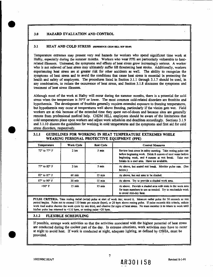
3.0 HAZARD EVALUATION AND CONTROL
3.1 HEAT AND COLD STRESS (REFERENCE CHJM BILL SOP HS4»)
Temperature extremes may present very real hazards for workers who spend significant time work atHalby, especially during the summer months. Workers who wear PPE are particularly vulnerable to heat-related illnesses. Untreated, the symptoms and effects of heat stress grow increasingly serious. A workerwho is not relieved of heat stress may ultimately suffer lift threatening heat stroke. Additionally, workersexperiencing heat stress are at greater risk for other accidents as well. The ability to recognize thesymptoms of heat stress and to avoid the conditions that cause heat stress is essential in protecting thehealth and safety of employees. The procedures listed in Section 3.1.1 through 3.1.7 should be used, hiany combination, to reduce the occurrence of heat stress, and Section 3.1.8 discusses the symptoms andtreatment of heat stress illnesses.
Although most of the work at Halby will occur during the summer months, there is a potential for coldstress when the temperature is 50°F or lower. The most common cold-related disorders are frostbite andhypothermia. The development of frostbite generally requires extended exposure to freezing temperatures,but hypothermia may occur at temperatures well above freezing, particularly if the victim gets wet. Fieldworkers are at risk because of the extended time they spent out-of-doors and because sites are generallyremote from professional medical help. CH2M HELL employees should be aware of the limitations thatcold temperatures place upon workers and adjust work schedules and deadlines accordingly. Sections 3.1.9and 3.1.10 discuss the guidelines for working hi cold temperatures and the symptoms and first aid for coldstress disorders, respectively. ______________________________________3.1.1 GUIDELINES FOR WORKING IN HEAT TEMPERATURE EXTREMES WHILE
WEARING PERSONAL PROTECTIVE EQUIPMENT (PPE)Tempera tare72° to 77° F
77° to 82° F
82° to 87° F
87° to 90° F
>90°F
Work Cycle
2his
2hrs
60 min
30min
IS min
Rest Cycle
5 min
5 min
IS minIS minIS min
Control Measures
Review heat stress in safety meeting. Take resting pulse ratebefore beginning work. Drink 8 ounces of cool water beforebeginning work, and 4 ounces at rest break. Take restbreaks in a cool area. Have ice available.As above, but seated rest break. Monitor pulse rate. (Seebelow.)As above, but rest area to be shaded.As above. Try to provide a shaded work area.As above. Provide a shaded area with seats in the work areafor team members to use as needed. Try to reschedule workto avoid mid-day heat
PULSE CRITERIA. Take resting radial (wrist) pulse at start of work day; record it Measure radial pulse for 30 seconds as restperiod begins. Pulse not to exceed 110 beats per minute (bpm), or 20 bpm above resting pulse. If pulse exceeds this criteria, reducework load and/or shorten the work cycle by one third, and observe for signs of heat stress. No team member is to return to work untilhis/her pulse has returned to <110 bpm, or resting pulse +20 bpm.
3.1.2 FLEXIBLE SCHEDULING
If possible, arrange work activities so that the activities associated with the highest potential of heat stressare conducted during the coolest part of the day. In extreme situations, work activities may have to occurat night to avoid heat. If work is conducted at night, adequate lighting, as defined by OSHA, must beprovided.
100239BC.SEA/7 & B 3 0 I 1 5 8 Revised 8-1-91

-f3.1.3 PERSONNEL ASSIGNMENTS
Rotate personnel and alternate job assignments to minimize overstress or overexcrtion.
3.1.4 ACCLIMATIZATION
Acclimatization can occur after a few days of exposure to a hot environment. NIOSH recommends aprogressive 6-day acclimatization period for workers. Under this regimen, the first day work level islimited to 50% of the eventual anticipated workload and exposure time. An additional 10 percent is addedeach day through day 6. With fit or trained individuals, the acclimatization period may be shortened by2 to 3 days, and work regimens should be adjusted to account for this.
3.1.5 FLUID REPLACEMENT
When enclosed hi an impermeable suit, workers who are physically fit and acclimatized will sweat moreprofusely than unfit or unacciimatized individuals and may therefore'actually face a greater danger of heatexhaustion due to rapid dehydration. This can be prevented by consuming quantities of water periodicallythroughout the work period. To maintain a workers' body fluids at normal levels, the daily fluid intakemust be approximately equal the amount of water lost in sweat. The normal thirst mechanism is notsensitive enough to ensure that water is replaced. Workers should be encouraged to drink more than theyneed when heavy sweating occurs. Water temperature should be maintained at 50° to 60°F. Smalldisposable cups should be provided that hold about 4 ounces. Workers should drink at least 8 ouncesbefore beginning work and then be encouraged to drink at least 4 ounces at each monitoring and restbreak. Workers should also be encouraged to maintain optimal fluid levels when not at work and to stopor moderate their alcohol intake.
3.1.6 TRAINING
Workers should be able to recognize and treat heat stress. Proper training and preventative measures areeffective to avert serious illness and loss of work productivity. Heat stress training should be included hisite-specific training sessions whenever work is performed hi temperatures that exceed 70°F.
3.1.7 COOLING PERSONAL PROTECTIVE DEVICES
Various designs of cooling vests have been developed. Each of these devices compensates for excess heatwith a pre-cooled material, such as ice or an artificial substitute. These vests are usually heavy and havea short effective duration (approximately 1 hour).
• MSA Core Control
MSA is a manufacturing a long underwear-like cooling system (core cool) that uses ice. Micro-tubing is used within the garment to circulate water. The manufacturer states the unit willoperate 2 to 3 hours per ice charge. The suit is attached with an umbilical to an ice watercirculation pump and ice compartment. A back pack model is also available.
• Vortex Tubes
A compressor may supply ah* to a vortex tube for worker cooling.
100239BC.SEA/8 A R 3 0 I 1 5 9 Revised 8-1-91

Supplied Air Coolers
These are supplied air respirators that utilize compressors equipped with chiller units to removewater and excess heat.
• Personal Monitoring DevicesThere are several new personal monitors which are considered to be first generation. One ofthese units is manufactured by Quest Electronics. This consists of a personal unit with atemperature probe that fits into a plug worn in the worker's ear. Studies have found that thetemperature near the ear drum closely resembles the core temperature. When the bodytemperature rises above a pre-set level a light and audible alarm are activated, letting the workerknow that he must rest and cool down. A second unit is produced by Metrosonics. This one hastwo sensors, one that is located on the worker's chest to measure the pulse rate, and anothersensor located under the arm that monitors skin temperature.
• Wetted Cotton Coveralls
Terry-cloth or other cotton coveralls can be a simple and effective auxiliary cooling garmentwhen used with impermeable protective clothing. Under environmental conditions of lowhumidity and high temperatures where evaporation of moisture from the wet cover garment is notrestricted, this approach to auxiliary cooling can be effective, relatively simple, and inexpensiveto use.
3.1.8 SYMPTOMS AND TREATMENT OF HEAT STRESS
Heat Stroke Heat ExhaustionRed, hot, dry skin; dizziness; confusion; rapidbreathing and pulse; high body temperature.
Pale, clammy, moist skin; profuse sweating;weakness; normal temperature; headache; dizzy;vomiting.
Cool victim rapidly by soaking in cool (not cold)water. Get medical attention immediately!!
Remove victim to a cool, air conditioned place.Loosen clothing, place in head low position.Have victim drink cool (not cold) water.
3.1.9 GUIDELINES FOR WORKING IN COLD TEMPERATURE EXTREMES WHILEWEARING PPE
Temperature Work Cycle Rest Cycle Control Measures
<32°F or<55° & raining
2hrs 15 min Review cold stress in safety meeting. Rest in a warm area.Drink at least 8 ounces of warm non-caffienated, non-alcoholic beverage at each rest break. Schedule a mid-daylunch break of at least 30 minutes in a warm area to beginnot later than 5 hours after startup.
100239BC.SEA/9 A R 3 0 I 1 6 0 Revised 8-1-91

3.1.10 SYMPTOMS AND TREATMENT OF COLD STRESS
Frostbite HypothermiaBlanched, white, waxy skin, but tissue resilient;tissue cold and pale.
Shivering, apathy, sleepiness; rapid drop in bodytemperature; glassy stare; slow pulse; slowrespiration.
Remove victim to a warm place. Rewarm areaquickly in warm (not hot) water. Have victimdrink warm fluids—not coffee or alcohol. Do notbreak any blisters. Elevate the injured area andget medical attention.
Remove victim to a warm place. Have victimdrink warm fluids-not coffee or alcohol. Getmedical attention.
3.2 GENERAL PHYSICAL (SAFETY) HAZARDS AND CONTROLS
The hazards listed below are common to all activities that are being conducted onsite. Task-specifichazards are listed in Sections 3.2.1 to 32.9.
Hazard Engineering or Administrative Controls
Noise > 85 dBA Hearing protection will be worn when conversations have tobe shouted at 3 feet. Noise monitoring required above85 dBA.
Steep terrain/unstable surface Personnel to proceed with caution,equipment as necessary.
Brace and shore
Moving vehicles Backup alarm required for heavy equipment. Observer remainsin contact with operator and signals safe backup. Personnel toremain outside of turning radius. If working in areas of heavyvehicular traffic, personnel will wear orange safety vests.
Slip, trip, fall hazards due to muddywork areas
Personnel to proceed with caution. Use wood pallets orsimilar devices in muddy work areas as needed.
Back injury Use proper lifting techniques, or provide mechanical liftingaids.
Protruding objects Flag visible objects.
Temperature extremes See Section 3.1.
Small animal traps Observe the area for traps. Wear steel-toed, steel-shankedboots.
3.2.1 CIVIL SURVEYING PHYSICAL (SAFETY) HAZARDS AND CONTROLS
The hazards associated with the civil surveying activities are similar to the hazards listed in Section 3.2.
10100239BC.SEA/10 A R 3 0 I 1 6 1 Revised 8-1-91

The hazards associated with the geophysic investigation are similar to the hazards listed hi Section 3.2.
3.2.3 SOIL BORING PHYSICAL (SAFETY) HAZARDS AND CONTROL
In addition to the hazards listed in Section 3.2, the soil boring activities have the following hazards:
HazardFlying debris/objects
Build-up of explosive gasesBuild-up of static electricity
High pressure hose rupture
Suspended loadsOverhead electrical wires
Buried utilities, drums, and tanks
Drilling hazards
Engineering or Administrative ControlsProvide shielding and PPE such as safety glasses, hard hat,and steel-toed boots.Provide 20-lb A,B,C fire extinguisher and ventilation.No spark sources within 50 feet of an excavation or heavyequipment. Ground as appropriate.Check to see that fitting and pressurized lines are in goodrepair before using.Work not permitted under suspended loads.Heavy equipment (e.g., drill rig) to remain at least 15 feetfrom overhead powerline for powerlines of 50 kV or less.For each kV > 50, increase distance 1/2 foot.Locate buried utilities, drums, tanks, etc. prior to drilling, andmark location. See Section 3.3 for procedures for locatingburied utilities.The drillers are responsible for providing drilling safetyprocedures prior to conducting work at the site.
3.2.4 GROUNDWATER WELL INSTALLATION PHYSICAL (SAFETY) HAZARDS ANDCONTROLS
In addition to the hazards listed in Section 3.2, the installation of groundwater wells have the followinghazards:
Hazard Engineering or Administrative ControlsFlying debris/objects Provide shielding and PPE such as safety glasses, hard hat, and steel-
toed boots.Build-up of explosive gases Provide 20-lb A,B,C fire extinguisher and ventilation.Build-up of static electricity No spark sources within 50 feet of an excavation or heavy equipment.
Ground as appropriate.High pressure hose rupture Check to see that fitting and pressurized lines are in good repair
before using.Suspended loads Work not permitted under suspended loads.
100239BC.SEA/1111
A R 3 0 I 1 6 2Revised 8-1-91
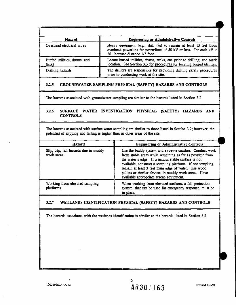
1Hazard
Overhead electrical wires
Buried utilities, drums, andtanksDrilling hazards
Engineering or Administrative ControlsHeavy equipment (e.g., drill rig) to remain at least 15 feet fromoverhead powerline for powerlines of 50 kV or less. For each kV >50, increase distance 1/2 foot.Locate buried utilities, drums, tanks, etc. prior to drilling, and marklocation. See Section 3.3 for procedures for locating buried utilities.The drillers are responsible for providing drilling safety proceduresprior to conducting work at the site.
3.2.5 GROUND WATER SAMPLING PHYSICAL (SAFETY) HAZARDS AND CONTROLS
The hazards associated with groundwater sampling are similar to the hazards listed in Section 3.2.
3.2.6 SURFACE WATER INVESTIGATION PHYSICAL (SAFETY) HAZARDS ANDCONTROLS
The hazards associated with surface water sampling are similar to those listed in Section 3.2; however, thepotential of slipping and falling is higher than in other areas of the site.
Hazard Engineering or Administrative ControlsSlip, trip, fall hazards due to muddywork areas
Use the buddy system and extreme caution. Conduct workfrom stable areas while remaining as far as possible fromthe water's edge. If a natural stable surface is notavailable, construct a sampling platform. If not sampling,remain at least 3 feet from edge of water. Use woodpallets or similar devices in muddy work areas. Haveavailable appropriate rescue equipment.__________
Working from elevated samplingplatforms
When working from elevated surfaces, a fall protectionsystem, that can be used for emergency response, must bein place. _____________________
3.2.7 WETLANDS IDENTIFICATION PHYSICAL (SAFETY) HAZARDS AND CONTROLS
The hazards associated with the wetlands identification is similar to the hazards listed in Section 3.2.
•12
100239BC.SEA/12 A R 3 0 I 1 6 3 Revised 8-1-91

3.2.8 BENTfflC/FISH SAMPLING PHYSICAL (SAFETY) HAZARDS AND CONTROLS
In addition to the hazards listed in Section 3.2, benthic/fish sampling have the following hazards:Hazard
Tripping, slipping, falling (wet surfaces,inadequate railing, waves, instability ofboat)Entanglement in lines, ropes, cables,equipmentFalling overboard
Overhead hazards (falling equipment)Collisions of boats
Navigation hazards (rocks, gravel bars,water level changes)Injuries from equipment (pinch points,sharp objects)Weather (cold, heat, lightning)
Engineering or Administrative ControlsCareful footing; halt operations if adverse weather conditionsare encountered
Buddy system
Adequate railing, flotation devices; halt operations if adverseweather conditions are encounteredProtective equipment (hard hats)Follow United States Coast Guard (USCG) boating regu-lations (speed, right-of-way, lighting)Familiarize with work area (charts, shallow draft jet boatwith experienced operator)Proper use of equipment, protective equipment (gloves),warning signsAppropriate clothing, monitoring weather; halt operations ifadverse weather conditions are encountered
3.2.9 SUMP SAMPLING PHYSICAL (SAFETY) HAZARDS AND CONTROLS
In addition to the hazards listed in Section 3.2, sump sampling has the following hazards:
Hazard
Confined space entry
Falling
Engineering or Administrative Controls
The sump, which is a confined space, will not be entered. Ifentry into the sump is required, a CH2M HILL permit andsafety plan are required (reference CH2M HILL SOP HS-17).
Conduct work from a stable surface as far from the sumpopening as possible. If a natural stable surface is not present,construct a sampling platform. If working from an elevatedplatform, a fall protection system must be in place. When notsampling, personnel will remain at least 3 feet from the edgeof the sump opening at all tunes.
33 PROCEDURES TO LOCATE BURIED UTILITIES
Miss Utility will be contacted at 800/282-8555 prior to any subsurface activities to locate and mark allburied utilities. The SSC is responsible for verifying that the buried utilities have been identified prior toany subsurface activities.
13100239BC.SEA/13 A R 3 0 I \ 6 k Revised 8-1-91

N
3.4 BIOLOGICAL HAZARDS AND CONTROLS
HazardsSnakes
Location and Control MeasuresPersonnel are required to wear long pants and steel toed, steelshanked boots. Observe the area for snakes.
3.5 TICK BITES, LYME DISEASE, AND ROCKY MOUNTAIN SPOTTED FEVER (RMSF)
Check often for tick bites. If bitten, carefully remove tick with tweezers, making certain to remove pincers,being careful not to crush the tick. After removing the tick, wash your hands. Disinfect area, and dress. Ifthe tick resists or cannot be completely removed, seek medical attention. Notify human resourcesdepartment within 24 hours.
Look for symptoms of lyme disease or RMSF. Lyme: rash that looks like a "bulls-eye," with small welt incenter, several days to weeks after tick bite. RMSF: Rash comprising red spots under skin, 3 to 10 daysafter tick bite. For both, chills, fever, headache, fatigue, stiff neck, bone pain. If symptoms appear, seekmedical attention.
3.6 RADIOLOGICAL HAZARDS AND CONTROLS
Refer to the CH2M HILL Waste Management and Industrial Processes Discipline Health and SafetyManual, Volume 2, for standards of practice for operating in contaminated areas. ___________
Hazards
None anticipated.
Controls
CH2M HILL personnel who have been issued TLDbadges will wear them.________________
3.7 HAZARDS POSED BY CHEMICALS BROUGHT ONSITE
Refer to CH2M HELL Hazard Communication Program Manual, which is available from the CorporateHuman Resources Department in Denver. The Project Manager is to request Material Safety Data Sheets(MSDSs) from the client, or contractors and subcontractors, for chemicals that CH2M HILL employees arepotentially exposed to. The MSDSs for the substances listed below can be found in Attachment 2 of thisdocument.
Chemical
IsobutyleneHydrogenPentaneMSA sanitizerNitric Acid*HexaneMethanolAlconoxHydrochloric acidSulfuric acid
Location
Calibration gasCalibration gasCalibration gasDecontamination areaDecontamination area, sample preservativeDecontamination area, sample preservativeDecontamination areaDecontamination areaSample preservativeSample preservative __________
"Nitric acid can react with some of the known contaminants of concern and cause cyanide gas. When usingnitric acid, do so in a well-ventilated area (i.e., outside) and monitor for hydrogen cyanide (see Section6.0).
14100239BC.SEA/14
f t R 3 0 l 1 6 5Revised 8-1-91

^
A B 3 0 I 166

COCD
o\ou
cu
&03
3<X>
1iuaoaataieUao2
oe
cucu
oB.
1
UQ
0_]"1^
sg
*^s1Eis
Chem
ical
to(N
— «
iS"-2.2 •—i ™|lT3»3 S*2.2
41i &yj U
Head
ache
,eq
uilib
riur
n§—
cuCuofl
=r »«•=!Z*<*~> mO vi0 O
O 00
I1,1,1
-Tric
hlor
oeth
ane
(1,1,
1-TC
A)
o
—
eOu
1
"t•SCU
111CO
M
1
Naus
ea, v
<de
rmati
tis
ECuo
(QU
E&
<s
ooso
oi00
I
11 , 1
,2,2-
Tetra
chlor
oeths
^p—
_oCB
1
.E•S
1
•aCO
§
Sg§•*"
ia§
<
oo
QUoo
1,1-D
ichlo
roeth
ane
v§^
cogIS1g
%
i§ ^O e^
EI cxCu
g•*
IBO
E Mr- ^<1 io ts
OQ Q3 U00 CO
1,2-
Dich
loro
ethen
e
incK
^
1o"
1S§18oB
1:1« E
1CU
gm
ii
=r sr an BO^>^> ^<«f "§>tt
O O 2 rf —
* ^ D D UO co co oo co
2-Bu
tano
ne(M
ethyl
Eth
yl K
etone
]
?ieK
iu>2T
'i•oeu
gISiIfll11g
0g•n
g
5— aotx BO^dao Srer|t!O <S (NO — O
^ D SO Eo oo
^^
12-He
xano
ne(M
ethyl
But
yl K
etone
]
j2
§g•tt
•o
<£§
18
i
j2
2
OO
*1 W«lM E aE * E
00 <N TftN O VO
OO OO </)
|| 2-
Met
hyln
apht
hale
ne
_j2
Irrita
tion
j*
2
00 00
E gf** ^O0 0
5 u1/3 t/)
I4-M
ethyI
-2-P
entan
one
j2
o1I_g
•oiu
J2
2
BO&0<¥ ^
E oots o ts
as da QD D tf5/3 1/3 C/0
1Acen
apht
hene
....
MSOs
* ft
•§.3
I"1JS
9sS
liIIpjfr
8cTcs
1o(N
60 00
s sfs|O O — •— (N
O oo co oo o:
Aceto
ne
p-
bo.S'i>?i
TJ
| He
adac
he,
1E
<nU
1inO
ao<3Erngo
tLC/3
T
•

*o S3 *ts I fc
8>
£•08
|
COIs5*ssje
Sssa12
Sym
p
3Q
I
0 *
a,
•S1
I
s
wCM
Iooe
tn
I
*? P **! ^- r-»O O VO — • VO
•4; <• p£ ffl Q> 5 3 uO co co cn co
1
a ffl QD D SC/3 CO W3
P0
g
irrita
tion,
mus
cliin
irrita
tion,
skin
*
t
!
s — f'* f~ <*>~ ^ ON m TCN O <n >O OO
I"oCO
'iCO
raU
0d
ON ts.
o d
O co co
u
03
I
1's,
•Il
03 Q5 3 U3CO CO CO
u•a
2
t
60 60 60
60 60 ME E r
O\ *•« ^Nr *«; i-i
o a a3 D UCO CO CO
BU
CQ
OCOcc
COaS

coCD
cn
Os0 acu
Cu
£•85gS
COI
ao£
i
aB
O
I.S
CO -a
3Q
a
aI'i
s gQ is,
i
e
i
IIIo aD Dco co co
.S•o
.p
e
i
J
60 60
J|1
t 0 C
o 03 Q3 3 WCO CO CO
1
g03
•o
(S§'i<sI
co co en
u
I
o€
00i
IIIEL13
oAO
£S HI1!oe ^ E E Eo o — w>
±- tQ& D DCO CO CO CO
£03
cn
O52-aU
Jf w
OO TT £ V)
O O — — —'•
i; ^ a m Q> ^ 3 D EO CO CO CO CO
md
8
60 „ M
l«s,^feo B S cs cfO 00 ff\ ^J*•- es —« •<» os
O co co to «
irvB» *.U <N
v>tS t-
E
§o o
oiCO
6
asO
•H* M^ •nlrfl
Is 1OO Os - .«s p po o o
> jj Q> ? tLO co co
|
6

b, *V
Sum
mar
y
8Ba"oIaB
i2ao
o
J
1
"S
u
oo(N
O
o"
csU
1
Si.o
o mO -^
11 S.IS
e |>li>E^!
* i JBM * *
O CO CO CO CO
noge
nic
I<so
oi ad QD D WCO CO CO
Z
I
qo
tiff!•0 g ^ os r-«n P — vo —•» o f~ «S fn
O CO CO CO CO
u.
§D
I ..LM CO
X ^3
f.lII11:1«"-1>S <8 oZ e -o
w
1I
60
lllllE oo £ E o
O ^5 r i ^F (N
*^ * * Q^ CQ ^^
O CO CO CO CO
1I
ufn
t
» §J: :_«>^e S'gng.jbC ff ISr~* oo c «* c
*"! «-< O r4
O CO CO CO CO
o
llP sI §)
1112 o ea ° 3
"S3 uT «"J 8-aI.E ifil*Cu -o 5?
5-3
I
I
60I
E00 t-cnO O O
P3co co
=I
cp
CD
or
coQ
oo

I*COCD
-J
oinVop03a.
Sum
mar
y
1£ua"o43BS
1SaoU
o
00rj
a.•••4
I
3*Ja
ij. **S|
uEES
s1u
£
I|«f
irrita
tion,
nau
se
«g*o
5C
J
*
2
^M M
M M Ma E E^ ^^ *""— 00
a! da QD D UCO CO CO
i
1 D
iben
zofu
l
Z3
eo
1
1
i•o§
s'o.
1
m£ObE§enoT
1^M€M
8 £ <n ro ^™* ro
d ri d —
^ ei ffl D^ 3 D UCO CO CO CO
1J5
| D
ibut
ylpht
t-;
T!G
nors
, unc
onsc
iou
1
i<5
E£go"
1B.O
s001d
09
eu
fe^i•sg»
2o<=
| D
ichlo
rodi
I 1
2)
00
w*•Cycd
1§Iu
en O3 ^3 BE .«
1|
m -Q
iQ.
CN"
1Q.
§
ooHoo<aO — •"»odd
oi CD QD D Wco co co
4)
803
1
2
S
^•o§|VI
1
u
1
J2
J
00 60 BJ
w\ 00 '•^00 — Tf
K tti QD D £co co co
uE
Fiuo
rant
hei
2
y1ou
.
itf
inha
latio
n, in
gei
=P'Sg &
ll
^J2
2
OO|M
0$ 1cs d cs
oi as QD D Kco co co
| F
luore
ne
21
inge
stio
n
£3
1 Po
isono
J
2
1Ef\d
,„ ,
E
d
O
u•c
1U
1
I
^
1
.E•o
<S
+£
g
1
1
J
*
2
00 00M<<<g. ob ss \o r^
TT d d
oi tn QD D ttco co co
uc
1
1 ln
deno
(l,2
§5
•§So*,td
1•1fe"13*.1•* ew .2
ll
COEObs52^
l*•oo
JptJo d 5 — cs
> i: 6^ £5 c^ ? D D ffO CO CO CO CO
1

g
13£
i
I
A H 3 0 I 1 7 2

4.0 PERSONNEL
4.1 CH2M HILL EMPLOYEES (REFERENCE CHIM HILL SOP HS-OI AND HS-O:)
Employees listed below are enrolled in the CH2M HILL chemical protection program (CPP) and meet themedical surveillance, 40-hour initial training, 3-day on-the-job experience, and 8-hour annual refreshertraining requirements of Occupational Health and Safety Administration (OSHA) 29CFR1910.120.Employees designated "SSC" have received 8 hours of supervisor and 8 hours of instrument training andcan serve as site safety coordinator (SSC) for the level of protection indicated. There must be one SSCpresent during any task performed in exclusion or decontamination zones with the potential for exposure tosafety and health hazards. Employees designated "FA-CPR" are currently certified by the American RedCross, or equivalent, in first aid and CPR. There must be one FA-CPR designated employee present duringany task performed in exclusion or decontamination zones with the potential for exposure to safety andhealth hazards. The "buddy system" requirements of OSHA 29CFR1910.120 are to be met at all times.
Employee NameApril LloydDon MartinsonDoug BittermanDarren BracchiaEden BrittBrett DoerrKerry IliffLynn VogelMitch BormackIshmad WahdanStephen Brand
OfficeWDCWDCWDCWDCPHLWDCWDCPHLPHLWDCWDC
ResponsibilityField Team Leader; SSCSampler; Alternate SSCSampler; Alternate SSCSamplerSamplerSamplerSamplerSampler; Alternate SSCSamplerSamplerSampler; Alternate SSC
SSC/FA-CPR |Level C SSC; FA-CPR |Level B SSC; FA-CPR |Level B SSC; CPR |
FA ^
———————— ]FA |Level C SSC; FA-CPR |
— — HLevel C SSC; FA-CPR
4.2 HEALTH AND SAFETY AND FIELD TEAM CHAIN OF COMMAND AND PROCEDURES
4.2.1 CLIENT
EPA Region III: Eric Newman
4.2.2 CH2M HILL
Field Team Leader/SSC: April Lloyd
26100239BC.SEA/26 A R 3 0 I 1 7 3 Revised 8-1-91

1u>sIPrc/5ra
13
o_o;
C/3 C/5 C/3 C/3 Qw c d & <!O 03 ?o • • r?
yi >— p p pso t^i w ^^ o_ „ oo o to3 3 g "» 00
W W I ll.""
Om»
fUJ
to
3QP[3
T3 '2
1-|
0.
Iffi
s.<Tex
i.1'I3*2°S-<B»
2jM
S*1MM
i
C/3 00 C/3 Qra G c <sa 03 ya r?
<j\ to *. O;_ "- ON j,j
&•*•TO JOQ *Si
to{•/!
t3T3
nPS
t lOO2
a-'oS »o O
n g• &•cro j
° B/(^ «
li:1 10- §re J^^ H
« sB>
1
i10
0U)to
CM
O3 Cfl
0 O
8 —
3 3
ere ere
o•o
Ol
io«
l!rro aw OK. on
B S'
^ §•'o ^*,
°- o.O Ptp1 2
ft§ $||"1
ooib.o
"5 s?
IfO1Oe
wo1•S'
O3 (/I C/3 C/5 0w cj G &O 03 !»••.?
H- p\ 10 0 0*> tj Oj G> O
3 3 S ON
%CTQ OQ .Ǥ,
""
00
1g.W
|«
isaG3
' I
|
£.!
1O
2>p3
1£3
o 03 ?o •• r?
-o — *. o o— VO 3 to O
3 3<| g S
OQ (TO —
Oto
fg3
i3
0. 0- flj1 S "m
§•• 1- §
& §S O<
M^ r^
3 o
£+• 03
If
110 g.
O En"
- |oB
2tr*
1
C/3 C/3 C/3 OW C G •<!O 03 JO rr
ft. tO ON O\O 3 °^ O
fS^ cro. cro
Oto
1U)
Zr
l!§
—f3
1
C/3 C/3
O CO
— —
3 3
JQ CTQ
w.•T31
to0
*"rt^rt3
Ifi!§ §B 0.f>. aa. §S Sit irritation;
matitis; coili
o' 8S §
I5*
00b\VO
9§1
|3"1?n3
§.
o'3
"dP
H "
JT*O*-!
r. t
O
Symptom
s
^rth— *
00
ffo1n9M15'a3To
f«fO
1CA
i3as3
&3
ffi*^J
O
r .
CDooor

sKSo
CD
• Jcn
§BCJ*
§
oo oo oo
^ M «bo o\ 53 3 3JQ 00
cro oo (^
oto3
1
r
Irritation
Zr
1
0
I*""
n^™^
CO
oji.
1oo
p
3
1
Ulo
1u>Eye, nose, and throat irritation; sneezing; coughinweakness; sweating; headache; dizziness; nausea;vom
iting; chest pain; dermatitis
00
Z
8CO
sP
o1^
p?
to
1OQ
p—3
1OB>
'ul
1
cn
1&5
f
A,
o.
B!•*•CO*
Zr
f ^P 2_
l"exon*O
fCg.w
00 00 00 00 Qw c G <s13 po ?3 ^ r?IsJ OO •— ' p W
^,00 ^5, 3 o^oo (^oo ;s "~
obu«
1Op*j
S
Headache, vertigo, nausea, vomiting, coughing,
weakness
2r
fB3
an
00 00 00a c Go 03 you> to »-3 *0 t>J
00 OQ
, ^0
•n3
Ui0o
1
Eye irritation, headache, confusion, excitement,
nausea, vomiting, abdom
inal pain, bladder irritatiprofuse sw
eating, dermatitis
§
poO
2|§"3. nQ. 3tt^ (0
1a.
1CfcEJI'S.
I00 00 00 00 Q
oo to u o to
III!400
u>i•a1
n85^i"o§sTJ
Fatigue, weakness, sleepiness, light headedness,num
bness and tingling of limbs, nausea, eye and
skin irritation
<!—*t—*
to
2i
i1o.^|
00 00 00 00 Om C G ^ 5sO DO ?0 • • r?
-»J — £>. O O^4 P° ^ b b3 3 o o
m i^:^
ob
fU)
o
I
Vision and hearing disturbances, dizziness, nausej
vomiting, diarrhea, constipation, skin burns
f
2-
§oo§On
00 00 OO 00 OS G G asa co ?3 •? i?»— U) tO -O P—U> O O\ {_„ OO
a 3 ?3 3!3 QQ 3 gjj 00
oo oo
_
300_
B
§
00 C- oo?' i?3" S.
S3 £>
la*^3n. g
3 «35±' r*
I o
Z
n3-i31'
2
|o§i§§m»"
rpi
9£
I3
S?<»o
£oBs-BseBG-O
5B
00
§3

ooen
rc/3m
5D
A R 3 0 I 1 7 6
°HfO|
Sediment
Carcinogenic'
milligram
per cubic meter
milligram
per literparts per m
illionCeiling (m
aximum
allowable concentra
c^
I
sp|§^i|^p
Permissible exposure lim
it (8-hour turnRecom
mended exposure lim
it (8-hour tThreshold Lim
it Value (8-hour time w<
Imm
ediate dangerous to life and healthPhotoionization potentialNo level found in literatureNone establishedN
ot applicableGroundwaterSurface w
aterSubsurface soil "Surface soil
W MM, Vt*
*§• 1 ^
£*tIf a1 £-1
Jj ,£,o
Chemical
Maxim
um
oloncentrati§SrH
r1 w
N^
Or
f5?
1Cfl
3
00
Know
n Contam
inants of Concern -S
emm
ary
BJre
s,

IoC/3
00
30COCD
^^,
£ 6OS-'g. o"^3^ O*
|1S <>e
c
oo2!*-JL/l
*t3T33
5'o•a•aS
Headache, eye irritation, nausea, vomitii
TO
OOVOOO
3zfi3'1—33'o
JO
5
o '
1TO
z£"H
Z
1 Eye irritation
Z
N5'
>3 GO GO GO Q
o w i ^ *•!i— .£. » tO -C*
2 \O O\ oo >—••U. VO ON OO
0 0 0 _ _o _ _ g 3-33 TO^CEO^
Zr
r
Skin and pulmonary system
irritation
Z
x*•<•,ICA
ys oo c/3 c/3W cH C s*o a ?9 •>Ul •— O Ooo — *. o_ ON -O 0
1§» 3 ^ 35*« era "*
TO
§~"O
1
i•o3
Dizziness; excitem
ent; drowsiness; stagj
eyes, nose, and throat irritation; nausea;derm
atitis
I I'f^5<(gera ~*
zF
<1"
P5*a.fr
||
o otic3 3(Q (|Q
TO
_>rQT33
0)
1
1
1
1P
Os100
os
H~-
I1c
EG 52 ftP -^ :?
<-ft O Oto o o_ o to
ill
SJ\Ji
23
O
§"o•a
Headache, vertigo, visual disturbance, ti
nausea, eye irritation, dermatitis
1
VOUl
H2.
I
Cfl GO GO GOa G G -gO D3 !» • •
— 0 0 0^ Ul j^ O3 \o oo o
|a ___ ^J ^Brf
CfQ GE5^ pp* Gp
N-§•aI
J°
•a1
Fatigue, weakness, confusion, dizziness,
dilated pupils, muscle fatigue, derm
atiti
O"
Sfn
ooboto
H
fa
GO GO GO GO O
^ ^ H-* \O O
3 3 3 B gTO TO TO l~"
^^
Z
Variable thiocyanates are not norm
ally iinto cyanide. They have a low
acute tolonged absorption m
ay produce varioustions, running nose, and occasionally dicram
ps, nausea, vomiting, and m
ild or idisturbances of the nervous system
.
1 = 1 1"*-s!?i
^
n
i
13"5
Concentrat
§'
Sw*< *»
H Sr1
Br
f1
t«
H I00 11
"1*I^ II3
SanO
1g3*affo
f
iiSumm
ary
*ooo3

4.2.3 SUBCONTRACTOR
To be identified in an addendum.
27100239BC.SEA/27
A R 3 0 I 1 7 8Revised 8-1-91

5.0 PERSONAL PROTECTIVE EQUIPMENT (PPE)- INTRODUCTION
Personal protective equipment (PPE) ensembles are designed to protect workers from the potential onsitephysical and chemical hazards. They are based on the current knowledge of the site and may change asmore information becomes available. General descriptions of the EPA levels of protection are discussed inSections 5.1 through 5.4. The specific PPE requirements are listed by task in Section 5.5. Because ofanticipated contaminants and their concentrations, the initial level of protection varies; Section 5.6 outlinesthe initial level of protection by task and location.
5.1 LEVEL D-GENERAL
In general, Level D protection is used when low levels of dermal and respiratory protection are required.The following equipment is typically required:
CoverallsBootsHard hatsHearing protectionSafety glasses or gogglesGloves
Level D can be modified when a higher degree of dermal protection is required. The material that thecoveralls, boots, and gloves are constructed of is dependent of site contaminants.
5.2 LEVEL C-GENERAL
Level C protection is used when a higher level of respiratory protection is required. Typically, Level Cprotection also has a higher degree of dermal protection than does Level D. In general, the equipmentrequired for Level C is the same as that required for Level D except an air purifying respirators (APRs) areused. APRs can only be used if the following conditions are met: the atmosphere contains 19.5 to25.0 percent oxygen, there is an approved cartridge for the chemicals that are present, personnel havemedical clearance to wear a respirator, personnel have been fit tested within the past year, and personnel donot have beards.
LEVEL B-GENERAL
Level B protection is used when a higher degree of respiratory protection is required. Situations thatrequire this level of protection include: oxygen deficient atmospheres, atmospheres that have chemicals forwhich APRs are not approved, and atmospheres that exceed the limits of APRs. Typically, Level Bprotection provides higher dermal protection than Levels C and D. The equipment required for Level B issimilar to that required for Level D with the addition of air-supplied respirators. Prior to using Level B,personnel must have medical clearance to use a respirator, must have been fit tested within the past year,and must not have a beard.
28100239BC.SEA/28
A B 3 0 I 1 7 9Revised 8-1-91

o
« S
^ *
lid
iss
Ii£I
Cfl
1bga.<nS£wipaw
IwIJ
I
j I li^slsl^ S ^ t - O o J S - ^
iTS
II
_u : **- -OT 01) *•a ao-o a•a §>| av^ »w "• MS> S> M -S« «Sten co «2 S"
n*i,i•T3 fe M -O S C4> ° to U •* S ui^ M -^ « g ^
•O
15 ^
00c'?,
a-
•z
*o
s i i Ij J S ^ ^ S g?|Iii ,
MTS a•a ai aw
S-g.
S
iilillliCO c / l *u«3 MA CUO
•a
a
ill!
o11
f
A R 3 0 I 1 8 0

5.4 LEVEL A-GENERAL
Level A is used when maximum dermal and respiratory protection are required. The equipment requiredfor Level A is boots and gloves, a fully encapsulating suit, and an air-supplied respirator. Prior to usingLevel A, personnel must have medical clearance to use a respirator, must have been fit tested within thepast year, and must not have a beard. This level of protection will not be used at the site.
29100239BC.SEA/29 A R 3 0 I 1 8 ! Revised 8-1-91

oJ
0) t«60 .fa
(2 I*Ctf
81
S
IHZ
Sa&w
ei
V)Ift
L. 1 > C
° S |.i
| ^^h
£ 5 o "S "ob
i
£
•a .^£• £? « -5 S•a - ss t lC/3 1/3 tS M Q.
1,1
1
o c *a o VS §.i il? *s 1<c .o on g .op
^ o o S o vd
sl s j— o S" S
14S1*Illll»•O
«2 *
II
i)^c oG. u
J M
3 i &.a
Illlll| g-s g s II o S 'oh Q. Q.
il•81.8iallss S a1-85
- o
lilli
-S 'a.218
,« i jj s|| S 1 1 "i
* J)C V) « W5
5 S f-°
S £3 "$3 o "iI 1 11 |m 6 8 s n
.3M
I1
1
I1
si s..l|*il'S -5i)4 •§ BO
o ""
a o§ -o a4 §>! a^f fS 1 §
. g
Q =3
s1s
t/5O
i
f l R 3 0 l 1 8 2
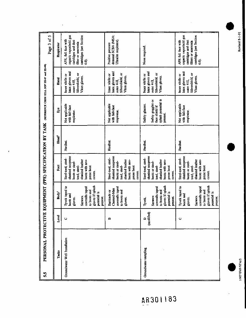
om
'5,
3 :2 sq B
1 > 8 * S* .2 «P fc W>
s •§J2 O 83o.on E
Mllls
1
1£
•a ^i o„ «u "° S
.~:ll£ * o w >
H -3, 4 - oou, ^ u Jj c*
1 1 1 1 1
si s .IJUIi
«i |« -- • ••
III
1
III f tilvi en <2 «•
P= 2 ^— ^ 'a.If S
CO2
U£uu0-</)
£fc
&IuI0.J
o
a.
x
. c
I
«-rf e io "3 ™ -S ^I 'SS l 'S ' l -S .2 J i M . J i M v C
l l l ^s f l sall a-g J s.8
8 "° "" '5 5
||{l
Id Is
-ts^-a
§H t/3 S 3 ~5k> -a ll-
ol
3S
iI
.f
AE30H83

<4HO
IB
S
S
O
1SuI
eb
HU
IEd
J35
I
v>
CO t?s,|^ 'D.
_ as r\1^- „«" 0.1. £r'5
<2-S 5
i I^S^S S o >7 oa C •Sn ^- ,
ia
s |£
1 a 1^ gM £ o "S "ob
o * •
HIill
s£
IJUloa 6 8 2 "M
3 "
DO
VI
13
1
gVI
"on
co to <2 5T 5.
gx — -
1 I'S
IQ.
iiCO
g-2
I
•ote S o &o
on ob.2 S. w
c! S« 1-1.
. g"S gs. fl
•g > p .
S'v ° "8III 1
§•2
I
41
'ab£••8en
1 i 1 iT3* C « "3 « 5 P
S^sl-8- i l . i
fill til 11co 1?3 ^ S to JD a. o
l
DO
ffl
1
00
I
C/3cs
A R 3 0 I

wft-
Iww
Ilid
Ie.
<z
I«o.
Bas
•aaa
8.S 1
i H I I .il III Is -a -a K > -a
sS's-z * 2
I
I
- S SL-o° 5 3 §i -1n 5 8 s •§»
I "
f"5.
1I
V)o
A R 3 0 I 185

zc
1HC—ta
ir «
z
O
siCUc<=fiCJ
5wr-enzcenUOS
r;
•Os
cs£
•8
C£
C ™
i i! i3 -n"2 Sj "S J1/1 ™ '>_il j; ^
•— ^ OT
O ? §'— 5i <J3 5J o
'^ S -0
J 3 ^
M 5 5c
1 Jl
i !|o £ £.£ -rn to eo> 3 = C
Z -S 6 U
1/53
I
U
1 'S§. =
i Mlo t ~" u_^ 8 =| g•5 K ,*° y *5M - "3 "3 "*C = p ~C -
1 i PagO j: t = u _ = ;j O
f-l ^ g_f
11 fl^.E ^- — y .1,= g = i" iC c . ^ t. c•/s O R! £1 in ^o So -c u = §~ T "* O ** L"3 *™ ^ ij £ ^
CC U E C ^ £
30•o
So
A R 3 0 I 1 8 6

•3O
s.
f~*
Sfegds1CdU
i
iH
USuCda.HZ
gauogOS0HZOsZ
q
c•
2.0
"wU
Freq
uenc
y
<n
15o1
2Wl
S
<u|
V3e
>^'3Q
I
Mon
itor
cont
inu
ously
. Re
cord
read
ings
ever
y30
min
utes
.
1!3
1
1 1 ^
11?1 2 S
J no ,
R 3 W" sP i—)5^ >n >?£3 ^Sl ^.—t 1 *Oi O tN
"w£
1•o1
•I*.!Q RJ
a!o g
S
SotN
o go S
>,~Q
1
Mon
itor
cont
inu
ously
. R
ecor
dre
ading
s ev
ery
30 m
inut
es.
|£ CQo U1 M
§ %3 SU 0. * •*•*•g N g
I 1 0
0" 0~ 0\p ^^ vp0s vO O1*O o^ in
A ts V
13*
1|
&
IIO CO
!.!
cs0
:; O•S {5S <o %
^
1Q
60 -
O ^ S C o ^3 CQ•tz« ••3 ™ " j*^ «2 j|2
J 0.1 o1! S.I2 o S m « eb.5
3^3i g"s-c ««1 S Si^l 1N-jj |
*Q O C S3 "S CQ 2"g "^ u o 8 "« aJ »_) so e « J oo
'g "-o ""e e. ^e's I I1 I* g 2 8V J, 2 A
. C 0.•2 £
-£" s ".0 S 60— . « e•- .e 2M 53 §"
_e ^ f>
I'll oow *O "O *S
lilto • •"5 Q
'itr s"J 2 7_S tj >u. Q O
•<^
-S gg>j
^5 J a ^ 6-$ -1"3 > S H ^'w ^ * § .—
Q «
1 I0
oS) 1Si feo-u "oZ U
~ C ft
•S'i i*-• •-« tn
^S oo
" s §*.S ^ "*^ ^ ^ . _eft "O n3 *S~ S S "3.'> O O EU 00 Sb en
i*.y —'£ 2 eaS — " c3
'g.l'g•3>COU
aiiaiv'Ia
A R 3 0 I 1 8 7

160 _.
.S •& »
1 S -a« Ssf"" ° 0.
00 2 J2i •« g_u O Ji
s ^ ;|
1 'N1 If** a •J
1 ^ IJ II"eS V g'S -0 —5 'x s^ E *.5 c _o
0 •= 11§ * "s"!•J a 1 i i» -^ S3 .-@ « i :§.s§ 2 "= j ~^ u '"" e" ooI ! M IS1 i Is1 1§SH o e g g a sw 1 i g 1 1 i 1H I | 'I .2 ° fe •§§ •§ 1 -s | | | Sa- I il| |E|fa I 8 1 -o <§ a- .2O | « l i ! i ' § &11 !i| pi1^ « o «2 "5 S § rT*3 a' "§ I » i £ .j 2 OUO g o ' s
fc J2 Js ° I "S* 11 ... Pi11 III5 i! Ill
,i«1
al Le
vel
|
e
1
M
£
Q
I
V]e
II Su
rvey
ing
QIAl
l loc
ation
s
gi
|| Ge
ophy
sical
Inve
st!03
I
0s
i
2
1c
S
5
Form
er la
goc
D
1
1§"H.
ie
Ien"B.m
Focu
sed
soil
MW-9
1n'SCO
CO1
2
1
100.g3g
°°"
O
2
1
onito
ring
well
i
StN
G>"
eo1
c
Grou
ndwa
ter W
ell !
03
1
73
op
1,8 m
onito
rir
OT5.2
I•o1OO
Q,8s>V
All l
ocati
ons
oo
Grou
ndwa
ter S
ampl
O
1
All l
ocati
ons
i•a
| W
etlan
ds Id
entif
ica
Q12
All l
ocati
ons
eo^c
1 Be
nthi
c/Fish
Sam
pl
ffl
2
o1i
Sout
heas
t bo
oo
CO
CO
1•s<S•aK'IC
equi
pmen
t
osoa.IM<s»n
ou
u
00I
CO
a
A R 3 0 I i

I8j3
189

* -1« 2
*5
!60.0
II
% <*!H ->,
3 5 S g3S -5 -5 .S= § § •§•
- . j11lillllS
u^ &a Q. oa a. o
oA V 2
O(N
I
od.o
55
Cu0o
oo§ |c rs S
BJ — o.
.S> 'S os ,
.> pu a>
caT>§N
!CN >n? 3
o .-
ao e•S .2,S —si
Mon
itor
cont
inu-
ously
. Re
cord
ing
read
ings
eve
ry30
min
utes
.
Q- ea |
1 1 £
a
!E E>o ._^ 9CN A
fe u S
illiiiO O O.
2zoffi
•ouui
'i
n-U
A R S O N

f>tM0f>O
9Pk
__K
ia-OenJ
S
Edwwasgua:
gMHgb!Ug55HU
M5o<H
g5g2i«53
OVO
Bs>
2.Q
"«<J^»
rs1fa
GA
1a
¥O•*•>O<<
—
"iJ2VIeaH
—
•*•»a4(gs•**wB
o"4-^
'cflUf4-*<MO
•ac13
_en
13«O'iJca^0t/300£»
J3?>,
^-aT3
.1
1JS2TJ
11COCO
S1 1£ <u
10 H<§ 25 «.3 "Seo >ts J3?. §4> *^wi's.feli« c o-|
M.S „ g.;i'e'S S11°^"1^1^d . • * ^ s s .a2J ^^ ^-* r* " '—* *— *^
.2 03 c « J3 g r i "a« 'C .2 S « g u S— S- i^ -a l jx "o«oJ5 t3 §,2^f-P?<^^?
2il/lii
1
uV
*rUrr
A R 3 0 I I 9 I

6.1 CALIBRATION SPECIFICATION
The air monitoring instruments will be calibrated as described below. More detailed information ofcalibration is available in the equipment instruction manuals. All calibration information will be recordeddaily in the log book.
Instrument Gas Span Reading Method
FID: OVA-128 100 ppm methane 3.0 ± 1.5 100 ppm 1.5 1/mregT-tubing
CGI:MSA260, 261,360, or361
0.75% pentane N/A 50% LEL± 5 % LEL
1.5 1/m regdirect tubing
Detector tube N/A N/A N/A Per manufacturer'sinstructions
Hydrogen Cyanide Meter 25 ppm hydrogensulfide
N/A 125 ppm Per manufacturer'sinstructions
Miniram N/A N/A N/A Per manufacturer'sinstructions
6.2 AIR SAMPLING
Method and Description:
Air monitoring will be conducted with direct reading instruments; no air sampling will be conducted.
41100239BC.SEA/41
& R 3 0 I 1 9 2Revised 8-1-91

7.0 DECONTAMINATION SPECIFICATION (REFERENCE CHJM HILL SOT HS-«)
Personnel
• Boot wash/rinse
• Glove wash/rinse
• Outer glove removal
• Body suit removal
• Inner glove removal
• Respirator removal
• Hand wash/rinse
• Face wash/rinse
• Shower ASAP
• PPE disposal method:Drum
• Water disposal method:Drum
Sample Equipment• Wash/rinse equipment
• Solvent rinse equipment
• Solvent disposal method:Drum
Heavy Equipment
• Power wash
• Steam clean
• Water disposal method:Drum
1
7.1 DIAGRAM OF PERSONNEL DECONTAMINATION LINE
Figure 3, 4, and 5 depict the maximum decontamination lay-up for Levels D, C, and B, respectively.Depending on task and sampling location layout, the stations shown in these figures may be consolidated.
8.0 SPILL CONTAINMENT PROCEDURES
In the decontamination area a liquid and sediment control system consisting of lined and bermed areawill be constructed to prevent contact of soils and permanent features. If a liquid spill occurs sorbentwill be used and the material will be containerized.
In the trailer, containers with chemical substances will be secured and the amount available will belimited. If a spill occurs, sorbent will be used and the material will be containerized.
Purged groundwater will be stored in 55-gallon drums. If a spill occurs, sorbent will be used and thematerial will be containerized.
If oils or other fluids leak from the heavy equipment, any affected media will be containerized and adrip pan will be placed under the equipment.
42100239BC.SEA/42
A R 3 0 I 1 9 3Revised 8-1-91

mCO Q 0>
.< Oa: >,OS< CB5*
O
g
I 5a .2 -agS,, 5 §5c <2 c " EOJ ~ 55 3 t ^
oc § O " °00 ^ —
2w•»-O
c_o»OLUa
^ o
IIa oQ I/)
v>
(0
Xo
^§&
IIa in
w =-J#(D <C (Do .*s
8|9Eo
A R 3 0 I I 9 U

iZilg IT< (0
oQ
I•8
=2:m in
o coco I?> CO
12CO .
CO
;lo
A R 3 0 I 1 9 5

m m
E
< "m
O
|OaQ
<n3O•atoN<c
s#c Q-A LU
<D
as
® 03
§.5"to
oLL
f t R 3 0 l 1 9 6

9.0 CONFINED SPACE ENTRY
No confined space entries are planned during this investigation. However, if they become necessary, anadditional health and safety plan and a permit are required (see CH2M HILL SOP HS-17, contained in theWaste Management and Industrial Processes Discipline Health and Safety Manual, Volume 1).
10.0 WORK PROCEDURES
10.1 WORK PRACTICES
As required by owner, personnel will check-in.No spark sources within exclusion or decontamination zones.Avoid visibly contaminated areas.No eating, drinking, or smoking in contaminated areas, or exclusion or decontamination zones.SSC to establish areas for eating, drinking, smoking.No contact lenses in exclusion or decontamination zones.No facial hair that would interfere with respirator fit if Level C or B is anticipated.Site work will be performed during daylight hours whenever possible. Any work conducted duringhours of darkness will require enough illumination intensity "to read a newspaper without difficulty."Each team member is responsible for recording the number of days onsite on then: timesheets.
10.2 SITE CONTROL MEASURES
Site safety coordinator (SSC) to conduct weekly site safety briefing. Meetings to include: generaldiscussion of health and safety plan; site specific hazards; location of work zones; PPE requirements;equipment; special procedures; emergencies; SSC records safety briefing attendance in logbook, anddocuments topics discussed.SSC to be notified daily of activities and levels of protection. SSC to record levels of protection inonsite log book.Post OSHA job site poster in a central and conspicuous location at the site.Determine wind direction.Establish work zones: support, decontamination, and exclusion zones, and delineate work zones withflagging or cones as appropriate. Support zone upwind of site.Establish decontamination procedures, including respirator decontamination procedures, and test.Utilize access control at the entry and exit from each work zone.Chemicals to be stored in proper containers.MSDSs are available for onsite chemicals employees exposed to.
46100239BC.SEA/46
A R 3 0 I 1 9 7Revised 8-1-91

Establish onsite communications. These should consist of:- Line of sight/hand signals- Air horn- Two-way radio or cellular phone if availableEstablish emergency signals. For example:- Grasping throat with hand-EMERGENCY-HELP ME- Grasping buddy wrist-LEAVE AREA NOW- Thumbs up~OK, UNDERSTOOD- Two short blasts on air horn—ALL CLEAR- Continuous air horn-EMERGENCY-EVACUATEEstablish offsite communications.Establish "buddy" system.Establish procedures for disposal of material generated onsite.Initial air monitoring conducted by SSC in appropriate level of protection.SSC to conduct periodic inspections of work practices to determine effectiveness of this plan.Deficiencies to be noted, reported to DHSM or RHSM, and corrected.
11.0 EMERGENCY RESPONSE PLAN (REFERENCE CHZM mu, SOP HS-IZ)
11.1 PRE-EMERGENCY PLANNING
The SSC performs the applicable pre-emergency planning tasks before starting field activities andcoordinates emergency response with the facility and local emergency service providers as appropriate.
Locate nearest telephone to the site and inspect onsite communications.Locate chemical, safety, radiological, biological hazards.Confirm and post emergency telephone numbers and route to hospital.Post site map marked with location of emergency equipment and supplies.Review emergency response plan for applicability to any changed site conditions, alterations in onsiteoperations, or personnel availability.Evaluate capabilities of local response teams.Where appropriate and acceptable to the client, inform emergency room/ambulance service andemergency response teams of anticipated types of site emergencies.Designate one vehicle as the emergency vehicle; place hospital directions and map inside; keep keys inignition during field activities.Inventory and check site emergency equipment and supplies.Review emergency procedures for personnel injury, exposures, fires, explosions, chemical and vaporreleases with field personnel.Locate onsite emergency equipment and supplies of clean water.Verify local emergency contacts, hospital routes, evacuation routes, and assembly points.Drive route to hospital.Review names of onsite personnel trained in first aid and CPR.Review notification procedures for contacting CH2M HILL's medical consultant and team member'soccupational physician.Rehearse the emergency response plan once prior to site activities.Brief new workers on the emergency response plan.
47100239BC.SEA/47
A R 3 0 I 1 9 8Revised 8-1-91

11.2 EMERGENCY EQUIPMENT AND SUPPLIES
The SSC marks the locations of emergency equipment on the site map and posts the map in the supportzone.
• 20 Ib ABC fire extinguisher• Industrial first aid kit• Additional emergency equipment: mobile telephone
11J EMERGENCY MEDICAL TREATMENT
The SSC will assume charge during a medical emergency until the ambulance arrives, or the injuredperson is admitted to the emergency room.Prevent further injury.Initiate first aid and CPR.Call the ambulance and hospital.Determine if decontamination will make injury worse. Yes—seek medical treatment immediately.Make certain that injured person is accompanied to emergency room.Notify the Project Manager of the injury.Notify the Health and Safety Manager.Notify the injured person's human resources department.Prepare an incident report. Submit this to the Corporate Director Health and Safety (WDC) andCorporate Human Resources Department (DEN) within 24 hours.
11.4 EVACUATION
Evacuation routes will be designated by SSC prior to beginning of work.Onsite and offsite assembly points will be designated prior to beginning of work.Personnel will exit the exclusion zone and assemble at the onsite assembly point upon hearing theemergency signal for evacuation of the exclusion zone.Personnel will assemble at the offsite point upon hearing the emergency signal for a site evacuation.The SSC and a "buddy" will remain onsite after the site has been evacuated (if possible) to assist localresponders and advise them of the nature and location of the incident.SSC accounts for all personnel in the onsite assembly zone.A person designated by the SSC (prior to work) will account for personnel at the offsite assembly area.The SSC is to write up the incident as soon as possible after it occurs, and submit a report to theCorporate Director Health and Safety.
48100239BC.SEA/48 A R 3 0 I 1 9 9 Revised 8-1-91

11.5 EVACUATION ROUTES AND ASSEMBLY POINTS
In the event of an emergency, personnel will evacuate the area using an upwind or cross-wind route andwill assembly in the west comer of the site, near the intersection of 1-495 and Terminal Avenue. If thedesignated evacuation routes or assembly point is unsafe, the SSC will identify alternate routes and analternate assembly point.
11.6 EVACUATION SIGNALS
Exclusion Zone
The "Buddy" system.
Site
"Buddy" system
12.0 EMERGENCY RESPONSE TELEPHONE NUMBERS
SITE ADDRESS: Brandywine Chemical Company Phone: 302/656-5428600 Terminal AvenueNew Castle, DE 19720
Police Phone: 302/571-4512
Fire Phone: 302/571-4414
Ambulance Phone: 911
Water and Electric: Phone: 302/323-2330
Hospital: St. Francis Hospital Phone: 302/421-4100
Route to Hospital:
See Figure 6. Take a right out of site onto Terminal Avenue. West on Terminal Avenue to Castle Road(Route 9). Turn right (north) onto Castle Road. Castle Road turns left and merges with Christiana Avenueinto 4th Street. Proceed northwest on 4th Street to Washington Street (Route 202). Turn right ontoWashington Street and proceed to 7th Street. Turn left on 7th Street and proceed to Clayton Street.St. Francis Hospital is at 7th and Clayton Streets.
12.1 GOVERNMENT AGENCIES INVOLVED IN PROJECT
Federal: EPA Region III Phone: 215/597-0910Eric Newman
State: DNREC Phone: 302/323-4540Margie Zhang
49100239BC.SEA/49 a n o n i r» n r* Revised 8-1-91A R 3 0 I 2 0 0

Figure 6Route to Hospital
100239BC.SEA/5050
A R 3 0 I 2 0 I Revised 8-1-91

13.0 EMERGENCY CONTACTS
CH2M HILL Medical Consultant
Dr. Kenneth ChaseWashington Occupational Health Associates202/463-6698 (8 AM to 5 PM EST)202/463-6440 (after hours answering service;physician will return call within 30 minutes)
WDC Occupational Physician
Name: Dr. ChasePhone: 202/463-6698
PHL Occupational Physician
Name: Dr. BelflyPhone: 202/564-2229
Corporate Director Health and Safety
Name: Marty Mathamel/WDCPhone: 703/471-1441 ext. 4646
Site Safety Coordinator (SSC)
Name: April Lloyd/WDCPhone: 703/471-1441 Ext. 4321 (O)
_______703/527-5052 (H)_______
Regional Manager
Name: George Gunn/WDCPhone: 703/471-1441
Health and Safety Plan Approver
Name: Mollie Netherland/SEAPhone: 206/453-5000 Ext. 5342
Project Manager
Name: Bob Root/WDCPhone: 703/471-1441 Ext. 4314 (O)
_______703/715-0362 (H)_______
Radiation Health Manager (RHM)
Name: George Stephens/OROPhone: 615/483-9032 Ext. 531
WDC Regional Human Resources Department
Name: Cindy BauderPhone: 703/471-1441 Ext. 4243
PHL Regional Human Resources Department
Name: Pat WisnewskiPhone: 215/563-4220
Client
EPA Region IIIEric Newman215/597-0910
Corporate Human Resources Department
Name: Beth Brown/DENPhone: 303/771-0952
If an injury occurs, notify the injured person'spersonnel office as soon as possible after obtainingmedical attention for the injured. NotificationMUST be made within 24 hours of the injury.
100239BC.SEA/5151
Revised 8-1-91
&R3-0 I 202

14.0 PLAN APPROVAL
This site safety plan has been written for use by CH2M HILL. CH2M HILL claims no responsibility forits use by others, unless specified and defined in project or contract documents. The plan is written for thespecific site conditions, purposes, dates, and personnel specified and must be amended if these conditionschange.
PLAN WRITTEN BY: Mollie Netherland DATE: March 1993
PLAN APPROVED BY: DATE:
14.1 PLAN AMENDMENTS
DATE: CHANGES MADE BY:
CHANGES TO PLAN:
APPROVED: DATE:
14.2 PLAN AMENDMENTS
DATE: CHANGES MADE BY:
CHANGES TO PLAN:
APPROVED:
15.0 ATTACHMENTS TO PLAN
DATE:
Attachment 1: Employee signoff
Attachment 2: Applicable MSDSs
Note: Once approved, a copy of this plan shouldbe forwarded to Marty Mathamel/WDC.
100239BC.SEA/5252
A R 3 0 I 2 0 3 Revised 8-1-91

ATTACHMENT 1
EMPLOYEE SIGNOFF
The employees listed below have been provided a copy of this health and safety plan, have read andunderstood it, and agree to abide by its provisions. ||
EMPLOYEE NAME EMPLOYEE SIGNATURE / DATE
100239BC.SEA
53100239BC.SEA/53 A R 3 0 I 2 Q 1 4 Revised 8-1-91