Embed Size (px)
Citation preview

i
106010202-FS0001, R00
FABRICATION SPECIFICATION
SPARE MERCURY PUMP
REMANUFACTURE
May, 2020
This report was prepared as an account of work sponsored by an agency of the United States government. Neither the United States government nor any agency thereof, nor any of their employees, makes any warranty, express or implied, or assumes any legal liability or responsibility for the accuracy, completeness, or usefulness of any information, apparatus, product, or process disclosed, or represents that its use would not infringe privately owned rights. Reference herein to any specific commercial product, process, or service by trade name, trademark, manufacturer, or otherwise, does not necessarily constitute or imply its endorsement, recommendation, or favoring by the United States government or any agency thereof. The views and opinions of authors expressed herein do not necessarily state or reflect those of the United States government or any agency thereof.

ii

iii
SPARE MERCURY PUMP REMANUFACTURE
Date Published: May 2020
Prepared by OAK RIDGE NATIONAL LABORATORY
P.O. Box 2008 Oak Ridge, Tennessee 37831-6285
managed by UT-Battelle, LLC
for the U.S. DEPARTMENT OF ENERGY under contract DE-AC05-00OR2272

106010202-FS0001, R00
iv
SPECIFICATION FOR SPARE MERCURY PUMP REMANUFACTURE
DATE ISSUED May, 2020
LABORATORY ORNL
DIVISION / GROUP NTD
SPECIFICATION NO.: 106010202-FS0001, R00
PREPARED BY Adam Carroll
Mercury Target Team Lead Drew Winder
LEAD ENGINEER Makayla Edwards
Other WBS elements affected:
Signature / Date Rev 00 Rev 01 Rev 02
Prepared by:
Lead Engineer:
Mercury Target Team Lead:
SDE Group Lead:
Manufacturing Team Lead
QA Representative:
Reviewer:
REV NO. REVISION DESCRIPTION
0
Initial Release, See 106010200-CN0005
106010202-FS0001, R00
1
1 SCOPE Herein, the term “Seller” shall refer to the parties responsible for producing the Spare Mercury Pump (hereafter referred to as the ‘Spare Pump’) within the scope defined below and “Company” shall refer to UT-Battelle, LLC, and its representatives. The existing, unmodified Spare Pump and related components defined below will be delivered to the Seller by the Company. The Seller shall perform a series of operations to remanufacture the pump to comply with the current SNS operating conditions per the requirements of this specification. Key aspects of the project are as follows.
• Disassembly of the as-delivered pump • Replacement of deep grooved ball bearings • Removal and replacement of Flowserve mechanical seal • Modification of the pump Sump Tank Lid, Support Plate and Support Plate Weldment, Pump
Tripod Shaft Assembly, Lower Grease Bucket Catch, and various other pump components to accept the new seal and bearing arrangement
• Fabrication of a new Pump Sump Tank Lid, Seal Piping Support Assembly, Spacer Ring (if needed), Shim (if needed), and Functional Test Stand Assembly
• Re-assemble the modified Pump Assembly per this specification and the provided engineering drawings
• Perform helium leak checking of the pump assembly • Perform extended functional testing of the completed pump assembly Packaging and delivery of the completed Spare Pump, Pump Test Stand, and documentation to the Company
Any exceptions to this Specification or the Engineering Drawings identified in Section 3 shall be clearly noted as such in the Seller’s proposal documentation. Where exceptions are taken the Seller shall propose alternatives in the proposal documentation. 2 INTRODUCTION The Spallation Neutron Source (SNS), located at Oak Ridge National Laboratory in Oak Ridge, TN, is a neutron scattering facility in which a pulsed proton beam is used to generate neutrons by spallation in a flowing mercury. The mercury stream is circulated in a closed loop with a centrifugal pump that is specially modified for operation in a radiation environment. This specification addresses certain changes in the existing spare mercury pump required to accommodate advanced operating techniques developed since the initial facility startup. 3 APPLICABLE SPECIFICATIONS, AND DRAWINGS The following documents and addenda are a part of this specification to the extent specified. Where the specification appears to conflict with the requirements of a reference document, such conflicts shall be brought to the attention of the Company for resolution before proceeding with fabrication and assembly. The order of the drawings is atypical as a result of blending re-manufacturing of existing drawings, new drawings, and procedural drawings. The below table attempts to organize the drawings not by number, but by function. Within the disassembly and assembly drawings, some parts and assemblies that do not require modification or replacement may be identified by drawing numbers and associated drawing not included within the reference drawing package, those drawings can be made available upon request.

106010202-FS0001, R00
2
Document Number Shts Rev Title
Remarks
Fabrication Specification 106010202-FS0001 - R00 SPARE MERCURY PUMP
REMANUFACTURE This specification
Arrival Configuration / Disassembly Procedure
106010202-M8U-8700-A583 6 R00
SNS Target Systems, Spare Pump Remanufacture, Disassembly Procedure
Arrival configuration to Seller’s facility/ describes stepwise pump disassembly procedure
Modification to Existing Fabrication
106010202-M8U-8700-A584 6
R00
SNS Target Systems, Spare Pump Remanufacture, Sump Tank Lid Modifications
Defines Seller manufacturing requirements
106010202-M8U-8700-A398 4 R04
SNS Target Systems, Target Mercury Pump Components; Support Plate
Defines Seller component modification requirements (machining of part)
106010202-M8U-8700-A350 4
R03
SNS Target Systems, Target Mercury Pump Components; Support Plate Weldment
Defines Seller component final condition requirements (welding of new components)
106010202-M8U-8700-A438 3 R01
SNS Target Systems Mercury Process Pump Tripod Shaft Assembly (B02-576294)
Defines, location for welding Lower Grease Chute, Panels
106010202-M8U-8700-A627 1 R00
Target System Mercury Process Pump Tab, Lower Grease Bucket Catch
Defines Seller manufacturing requirements
106010202-M8U-8700-A639 2 R00
SNS Target Systems Process Mercury Pump Upper Grease Bucket Catch
Defines Seller manufacturing requirements
Replacement of Bearings Procedure 106010202-M8U-8700-A606 6 R00
SNS Target System Hg Pump Assembly Spare Pump Modification
Describes stepwise bearing replacement procedure
Fabrication of New Assembly / Components for Pump
106010202-M8U-8700-A607 4 R00
Target Systems Hg Pump Assembly Seal Piping Support Assembly
Defines assembly of piping structure to provide gas to seal

106010202-FS0001, R00
3
Document Number Shts Rev Title
Remarks
106010202-M8U-8700-A608 2 R00
Target Systems Spare Pump Remanufacture Sump Pump Tank Lid
Defines Seller manufacturing requirements
Assembly Procedure
106010202-M8U-8700-A605 8 R00
SNS Target System, Hg Pump Assembly Replacement Pump Assembly
Describes stepwise pump assembly procedure
Existing Components, Modification Possible for Alignment of Pump 106010202-M8U-8700-A437 1
R00
SNS Target Systems, Mercury Process System, Spacer Ring
Defines Seller manufacturing requirements
Sterling Fluid Systems Drawings 61-576294
1 - Shim, Ø19.00 O.D. x Ø11.00 I.D. x .225 thk
Defines shim for impeller adjustment, fabrication dependent on need
Functional Test Configuration and Associated Test Stand 106010202-M8U-8700-A589 4 R00
SNS Target Systems, Mercury Process Pump Test Stand with Hg Pump
Defines, assembly of pump in test stand
106010202-M8U-8700-A590 2 R00
SNS Target Systems, Mercury Process Pump Pump Test Stand Assembly
Defines, assembly of pump test stand
106010202-M8U-8700-A591 7 R00
SNS Target System, Mercury Process Pump Pump Test Stand Weldment
Defines Seller manufacturing requirements
106010202-M8U-8700-A592 2 R00
SNS Target System, Mercury Process Pump Housing Rod Clamp Weldment
Defines Seller manufacturing requirements
106010202-M8U-8700-A593 2 R00
SNS Target System Mercury Process Pump Lower Opening Cover
Defines Seller manufacturing requirements
106010202-M8U-8700-A594 2 R00
SNS Target System Mercury Process Pump Lower Opening Gasket
Defines Seller manufacturing requirements
106010202-M8U-8700-A595 2 R00
SNS Target System Mercury Process Pump Upper Window Frame
Defines Seller manufacturing requirements
106010202-M8U-8700-A596 2 R00
SNS Target System Mercury Process Pump Upper Window
Defines Seller manufacturing requirements
106010202-M8U-8700-A609 2 R00
SNS Target System Mercury Process Pump Steel Upper Window
Defines Seller manufacturing requirements – for vacuum testing

106010202-FS0001, R00
4
Document Number Shts Rev Title
Remarks
106010202-M8U-8700-A597 2 R00
SNS Target System Mercury Process Pump Upper Window Gasket
Defines Seller manufacturing requirements
106010202-M8U-8700-A598 2 R00
SNS Target System Mercury Process Pump Water Flow Baffle Assy
Defines, assembly of water flow baffle
106010202-M8U-8700-A599 2 R00
SNS Target System Mercury Process Pump Water Flow Body Weldment
Defines Seller manufacturing requirements
106010202-M8U-8700-A600 1 R00
SNS Target System Mercury Process Pump Upper Clamp Plate
Defines Seller manufacturing requirements
106010202-M8U-8700-A601 3 R00
SNS Target System Mercury Process Pump Water Flow Baffle Weldment
Defines Seller manufacturing requirements
106010202-M8U-8700-A602 1 R00
SNS Target System Mercury Process Pump Lower Clamp Plate
Defines Seller manufacturing requirements
Lift Fixture
11-99610 1 E Sterling Fluid Systems Motor Lifting Fixture
Defines Seller manufacturing requirements
Reference Drawings
106010202-M8U-8700-A527 2 R00
SNS Target Systems Replacement Mercury Pump Lower Grease Chute
Required only if original damaged during refurbishment Defines Seller manufacturing requirements.
106010202-M8U-8700-A528 2 R00
SNS Target Systems Replacement Mercury Pump Upper Grease Chute
Required only if original damaged during refurbishment Defines Seller manufacturing requirements.
Company Provided Components (No Modification Required)
106010202-M8U-8700-A463 1 R00
SNS Target Systems, Mercury Process Pump, Assembly Jig
For Reference Only: Describes a Company Provided Component
Sterling Fluid Systems Drawings 1199611-01
1 RJ Pump Lifting Fixture, 9080 Taber Pump Assembly
For Reference Only: Describes a Company provided handling component, shown in Figure A.3

106010202-FS0001, R00
5
Document Number Shts Rev Title
Remarks
Flowserve Drawing D0372017 1 P10
Seal Type: GTSP; Dual Pressurized-Face to Face – Cartridge
Describes Company procured component, shown in Appendix
Seller’s Procurement Requirements A-B Powerflex 753 AC Packaged Drive
- VFD Quote 1 0
Kendall Electric Quote for VFD and associated components
Defines Seller procurement requirement for VFD, shown in Appendix
Mott High Purity Gas Filter
Specification 2 0 Mott High Purity Gas
Filter POU-10-S
Describes the helium filter required for providing clean helium to the Flowserve seal
Specification
ASTM E499-11 2017
Standard Practice for Leaks Using the Mass Spectrometer Leak Detector in the Detector Probe Mode
Required for Assembly Testing
4 MATERIAL PROVIDED BY THE COMPANY Components and assemblies provided to the Seller by the Company are listed below. All provided components and assemblies provided by the Company shall be returned by the Seller at the completion of the project undamaged and in good working order.
• Pump assembly mounted on temporary handling and storage stand as shown in Figure A.1. • Drive motor mounted on a temporary handling and storage stand as shown in Figure A.2 • Pump assembly lift fixture as shown in Figure A.3 • Flowserve seal assembly as shown in Appendix 2 • Modified assembly jig (106010202-M8U-8700-A599)

106010202-FS0001, R00
6
5 TECHNICAL REQUIREMENTS
Remanufacturing of the Spare Pump shall be performed by the Seller as defined below.
5.1 Remanufacturing Disassembly 5.1.1 The Seller shall disassemble the Company provided pump per SNS drawing number
106010202-M8U-8700-A583. The Seller shall provide access and assist a Company representative with measuring the clearance between the pump rotor and pump casing as shown on drawing 106010202-M8U-8700-A583, Sheet 2, Detail B. The impellers shall be individually numbered with semi-permanent marker, the housing shall be marked to provide a clocking method, and the gap between each impeller blade and impeller housing shall be measured at multiple locations and recorded to at least 3 decimal places by both the Seller and the Company representative. The results of the inspection shall be included within a Dimensional Inspection Report to be provided to the Company.
5.1.2 The Seller shall provide a lifting assemblies and support stands for the disassembled components. A lifting fixture for the motor assembly shall need to be manufactured, drawing 11-99610.
5.1.3 The Seller shall protect all seal surfaces and reused parts from damage during disassembly and modification
5.2 Procurement 5.2.1 The Seller shall procure an AB Powerflex 753 AC Packaged Drive VFD for the Pump
Motor (quote for equipment provided in Appendix). The Pump Motor is a Reliance Electric Duty Master, 60 HP, 3 Phase motor. The identification tag for the motor is shown in Figure A.4.
5.3 Machining 5.3.1 The Seller shall remanufacture the Spare Pump Lid to achieve final weldment as defined
by SNS drawing 106010202-M8U-8700-A350. SNS drawing 106010202-M8U-8700-A584 provides stepwise instructions on how to remove the overflow tank. The Seller can propose an alternative procedure for remanufacture for Company approval.
5.3.2 The Seller may offer alternative methods of performing machining operations as part of the original offer or prior to implementation. All alternative methods shall be approved in writing by the Company prior to implementation.
5.3.3 The Seller shall have a 0.065 inch diameter hole drilled in the center of the hex head for installation of a wire in identified fasteners in drawing 106010202-M8U-8700-A605. The wire shall be installed prior to Functional Pump Test.
106010202-FS0001, R00
7
5.4 Reassembly 5.4.1 The Seller shall reassemble the pump per SNS drawing 106010202-M8U-8700-A605-R00
“SNS Target Systems, Mercury Process System, Replacement Pump Assembly”. 5.4.2 A representative of the Company shall be present for the reassembly of the Spare Pump. 5.4.3 The Flowserve gas seal has important installation and operational requirements. To ensure
correct installation, a technical representative from Flowserve shall be provided access to the Seller’s facility during seal installation and shall direct the gas seal installation process. The Company shall be notified at least 5 business days prior to the seal installation. A Company Representative shall be present during installation of gas seal.
5.4.4 The Seller shall use the Company provided “Assembly Jig”; SNS drawing No 106010202-M8U-8700-A463, to establish the correct pump discharge elevation and orientation prior to installation of the Displacement Tank Assembly. The installation of the Assembly Jig is shown in SNS drawing number 106010202-M8U-8700-A605-R00. Using the measured values, the Seller shall machine the “Spacer Ring” SNS drawing 106010202-M8U-8700-A437 to correct the position the discharge nozzle, if needed.
5.4.5 The Seller shall determine the proper elevation of the pump impeller with respect to the pump casing by temporarily installing the “Tripod Shaft Assembly” 106010202-M8U-8700-A438 and adjusting the elevation to establish the same gap determined prior to disassembly as specified in Section 5.1.1 of this Specification. The “Under Tripod Shim”, (Drawing 61-576294) shall then be machined to permanently maintain the measured gap between the pump impeller and the pump casing.
5.4.6 The Seller shall notify the Company when the impeller to casing fit has been established and enable a Company representative to perform a dimensional inspection. The Company representative shall use the clocking method established in Section 5.1.1; the impeller shall be clocked to the same position and gap between each impeller blade and impeller housing measured. The measured gaps must be within ±0.005” of the original measurements.
5.4.7 The Seller shall replace the two deep groove bearings supporting the shaft. The new bearings shall be packed with Chevron SRI NLGI-2 grease. The process for the bearing replacement is described in step 3 on sheet 3 and step 6 on sheet 4 of Drawing 106010202-M8U-8700-A606.
5.4.8 The Seller shall replace all fasteners removed during disassembly with new fasteners during final reassembly. All fasteners shall be lubricated with Loctite nuclear grade nickel anti-seize (LB-N-5000) per manufacturer’s recommendation. The tripod and gas seal fasteners shall be wired.
5.4.9 The Company may perform additional dimensional inspections prior to the Functional Test.
5.4.10 The Seller shall include the results of the inspections in the Dimensional Inspection Report documenting all Seller and Company inspections.

106010202-FS0001, R00
8
5.5 Testing 5.5.1 The Seller shall test the operational function of the spare pump with water for operating
periods cumulating in a total of at least 120 hours. The test shall consist of operating the Spare Pump through a range of speeds from 250 to 400 RPM with the pump submerged in a minimum of 36” of purified water. The pump discharge will not be connected to a pipe. A Company representative must be present during the start of this testing period and shall have access to Seller’s facility during the testing. General testing requirement are identified as follows
• The Spare Pump shall be monitored during the Functional Testing operation and never allowed to operate without direct supervision of Seller’s personnel.
• Continuous operation at 250 RPM, 300 RPM, 350 RPM, and 400 RPM for at least 8 hours at each speed
• Recording of total runout measurement of pump shaft in the 2 locations indicated on sheet 4 of Drawing 106010202-M8U-8700-A589.
• Extended testing at 400 rpm, for no less than 100 hours
• Recording at regular intervals (Seller to propose the frequency and method of recording for Company review and approval, electronic data collection is acceptable)
o Environmental temperature of test location. o Helium supply to Flowserve seal, flow rate and pressure o Periodic vibration analysis by Category II or Higher certified vibration analyst
per ISO 18436-2 (location, method, and equipment to be proposed by Seller for Company review and approval)
o Temperature on or near each bearing (Seller to propose location prior to re-assembly of Spare Pump for Company review and approval)
o Leak rate of bearing grease via weighing of grease released by each bearing per 8 hour run period
• Reporting o Noises or vibrations indicating fault or off-normal conditions
5.5.2 The Seller shall manufacture a test stand as detailed in 106010202-M8U-8700-A590-R00 and associated weldment and part drawings. The test stand shall be completely cleaned prior to Spare Pump installation to ensure no dirt, grease, chips, or other debris is present in the water.
5.5.3 The Seller is to test the rotating gas seal’s ability to seal the pump shaft. The Seller shall propose a procedure for a 24-hour vacuum leak check to the Company for review and approval. A Company representative must be present during the start of this testing period and shall have access to Seller’s facility during the testing. General testing requirement are identified as follows
• An acceptable leak rate must be less than 10-2 torr*L/sec
• Vacuum testing conducted before and after operational function test
• All water drained and dried from Pump Test Stand Assembly (106010202-M8U-8700-A590-R00) prior to vacuum testing

106010202-FS0001, R00
9
• The various ports on the Support Plate Weldment detailed in 106010202-M8U-8700-A350-R03 shall be capped and temporarily sealed
• The two clear acrylic windows (106010202-M8U-8700-A596) to be replaced with steel sheet (106010202-M8U-8700-A609-R00) during vacuum test.
• Prior to vacuum test, helium leak check the Test Stand with Hg Pump (106010202-M8U-8700-A589-R00) to ASTM E499-11 (2017), Standard Practice for Leaks Using the Mass Spectrometer Leak Detector in the Detector Probe Mode. No detectable quantity of helium should be sensed, except for potential near the rotating gas seal. If a leak detected (except near the rotating gas seal), adjust seal, correct faulty weld(s), and/or increase torque on associated fasteners until no leak is detectable.
• The Spare pump shall not be operating during this time and no helium to flow to the gas seal. The gas seal is designed to seal the pump shaft when gas is not supplied and shaft not rotating. A helium leak from this location is likely and acceptable.
5.5.4 The Seller shall procure an AB Powerflex 753 AC Packaged Drive VFD and all associated components for use during the test. Quote and details for required VFD included within Appendix.
5.5.5 The Seller shall install the VFD motor drive in accordance with the manufacturer’s specifications.
5.5.6 The Seller shall install Mott High Purity Gas Filter, POU-10-S to provide clean, filtered, helium gas supply to the Flowserve Seal. Seller can propose alternative filter to Company for approval. The gas supply shall be operated in accordance with the Flowserve’s instructions.
5.5.7 The Seller shall provide automatic interlocks to protect the pump during testing. Frequent motor starts and stops and rotating at low speeds (under 50 RPM) shall be avoided. Additionally, helium must be flowing to the seal, at pressures specified by seal manufacturer, when pump is rotating. If the Seller deems necessary, the Company may provide assistance to the Seller in establishing proper system controls and interlocks.
5.5.8 The Seller shall prepare a Functional Test Plan that outlines all aspects of the proposed procedure including monitoring methods, test cycles, safety interlocks, and specific test speeds for Company review and approval.
5.5.9 A Company representative shall be notified one week in advance when testing is to be conducted and shall be provided access to the test area for periodic monitoring.

106010202-FS0001, R00
10
5.5.10 The Seller shall provide a documented Functional Test Report which records all monitored and observed data and information. The Report shall specifically identify the following items:
• Pressure and flow rate of helium to gas seal • Excessive or harmonic vibration • Bearing temperatures (both bearings) • Noises that may indicate an off-normal or fault condition • Grease leaks from the bearing isolators • Vacuum leak tests • Total runout measurement of pump shaft in 2 places as specified on sheet 4 of Drawing
106010202-M8U-8700-A589.
5.6 Fabrication Requirements The Company drawings identified in Specification Section 3 are referred to in this specification as the Engineering Drawings. This specification and the Engineering Drawings shall constitute the official documentation from which Deviation Requests and Non-Conformance Reports are required. See Specification Section 6, Quality Assurance.
5.6.1 Exceptions Dimensional requirements for the Vessel Assembly are designated on the Engineering Drawings. The Seller shall clearly note any exceptions to dimensions, tolerances, or specifications indicated on these documents in their proposal submittal.
5.6.2 Weld Inspection Report The Seller shall submit Weld Inspector’s Certification Documents to Company for approval before welding commences. Welders shall be ASME Boiler and Pressure Vessel Code IX-2019 qualified. Seller shall provide an approved Weld Inspection Report with results for all welds.
5.6.3 Cleaning and Cleanliness Control The Seller shall control the methods of receiving, storing, handling, testing, and preparation of materials, and shall clean the materials to assure that all components are free of surface deformities, scale, corrosion, water, rust, oil, grease, and other deleterious foreign material prior to and after fabrication and testing.
5.6.4 Marking Requirements An engraved stainless steel plate shall be tack welded to the top surface of the Spare Pump lid in the location near the existing marking. The original pump manufacturing identification plate shall be removed. The new plate shall be marked with the following information in ¼” or larger lettering: Manufacturer’s Identification (and Logo if desired) Original Specification: 106010202-EQ0015-R01 Remanufacture Specification: 106010202-FS0001 Date of Remanufacture: XX/XX/20XX

106010202-FS0001, R00
11
5.7 Shipping Plan 5.7.1 The Seller shall disassemble the pump motor from the pump assembly after functional
testing and package the subassemblies and components for shipping. 5.7.2 The Seller shall mount the Motor and Spare Pump in the provided handling frames 5.7.3 The Seller shall cover the Motor, VFD, Lift Fixture and Spare Pump in waterproof plastic. 5.7.4 The Seller shall bag, label and package loose assembly parts in a box for shipment with
the Spare Pump. 5.7.5 The Seller shall plainly and permanently label the outside of each separate shipping item
the following Company shipping address: Attn: Makayla Edwards Seller Identification Purchase Order number: XXXXXXX (Assigned at time of order) Equipment Name: Spare Mercury Pump Equipment Identification: 106010202-FS0001 U.S. DOE c/o UT-Battelle, LLC Oak Ridge National Lab/SNS Site 9500 Spallation Drive Oak Ridge TN 37830
5.7.6 The Seller shall notify the Company of a shipping date no less than ten (10) working days prior to shipment.
5.7.7 The Seller shall transport the Spare Pump assembly and all related items F.O.B. via a commercial carrier to the SNS site in Oak Ridge, Tennessee.
5.7.8 The Company will inspect each shipment upon arrival. Any damage will be documented and if necessary, the Seller will be contacted to establish a plan of resolution.
5.7.9 The Company reserves the right to reject any or all items if the Seller deviates from the Shipping Plan detailed within Section 5.7. Seller may propose alternative Shipping Plan for Company review and approval. Failure to follow shipping plan or receive approval of alternative Shipping Plan shall not relieve the Seller of responsibility for delivery of the Spare Pump assembly to the SNS site undamaged.
6 QUALITY ASSURANCE
The Seller shall submit with the quote a copy of their written Quality Assurance (QA) Program or “Quality Control System” for evaluation. The QA Program/QC System shall address, at a minimum, all the required elements of ASME Section VIII, Division 1, and Appendix 10 as applicable to this project. The Seller shall ensure that all work is completed in compliance with their QA Program/QC System and the requirements cited within this specification. The Seller is responsible for the proper administration, sequencing and performance of all testing, inspections, and examinations, whether performed at the Seller’s facilities or at other facilities. The Company reserves the right to witness all tests, inspections, and examinations with timely notification to the Seller of such intentions.

106010202-FS0001, R00
12
6.1 Access for Source Surveillance Inspections As part of the Company’s Quality Assurance program, source surveillance activities may be conducted at the Seller’s facility or any sub-tier facility that the Company determines necessary to ensure that quality objectives are met. Such surveillance may include auditing and monitoring of production processes, in-process inspection and controls, chemical and physical certifications, final inspection and tests, preparation for shipment, and review of certification data. The Seller shall provide the Company representatives access to all data and operating areas pertinent to the contract. Source surveillance by the Company representative shall not constitute product acceptance by the Company and shall in no way relieve the Seller of the responsibility to furnish acceptable items.
6.2 Calibration Program All equipment used in tests, inspections, and examinations shall be calibrated in accordance with the equipment manufacturer’s recommendations and the Sellers QA/QC Program requirements. All equipment shall be uniquely identified and tagged in some manner to indicate the date of last calibration and the date when re-calibration is required plus the status of the current calibration. Procedures shall be established for correction of out-of-tolerance equipment. The procedures shall provide for tagging and removal of such equipment from the work area. Procedures shall be established for re-testing or re-inspecting of affected assemblies when out-of tolerance equipment has been used for testing or inspection.
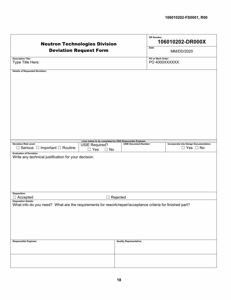
6.3 Control of Non-Conformances The Seller may use SNS-NTS-ENG-FM-002-R00 form provided within the Appendix or, if approved, its existing nonconformance program to identify, report, and recommend disposition of all non-conformances. Any dispositions that would leave any remaining nonconformity unresolved must be submitted to the Company for review and approval. The request shall identify the affected item(s) by name, serial number, the drawing/ specification number and revision number, and indicate the specific requirement which has not been met, and the applicable references for that requirement. Each unresolved nonconformance shall be reported separately for consideration. The Seller’s description of the nonconformance shall include a proposed corrective action and a time schedule for its implementation. Note: The Company’s acceptance of a proposed corrective action for a nonconforming condition in no way limits or affects the warranty provision of the Agreement, nor does it establish a precedent or obligation to accept other existing or future non-conforming conditions subject to the provisions of the Agreement.
6.4 Deviations The Seller may propose deviations from the specifications, drawings, or other technical requirements of the procurement using form SNS-NTS-ENG-FM-001-R00 provided within the Appendix. Where time is a consideration, the Seller may communicate the proposed deviation directly to the Technical Project Officer (TPO), with a copy to the Company’s buyer. The TPO will evaluate the technical aspects and recommend acceptance or rejection to the buyer, who will communicate acceptance or rejection to the Seller. The request should identify the affected items, drawing/specification number and revision number, a description of the proposed deviation, and justification for the request.
6.5 Acceptance The following criteria shall serve as the basis for final acceptance:

106010202-FS0001, R00
13
• Receipt and approval of all documents listed in Section 7. • Verification by a Company Quality Assurance representative or the Technical Project Officer
that the Seller has produced the Spare Pump Assembly in compliance with this specification.
• Receipt of a Certificate of Compliance (COC) from the Seller. The COC shall be submitted to the Company for written approval prior to shipment.

106010202-FS0001, R00
14
7 DOCUMENTATION Seller shall submit documentation as referenced previously in this specification and listed again in the following table.
Document When Required Section Sellers Quality Assurance Program With quote 6.0 Exceptions to Specification or Engineering Drawings With quote 5.6.1 Deviation Requests As Needed 6.4 & 5.6 Non-Conformance Reports Prior to Functional Test 6.3 & 5.6 Weld Inspector Certification Documents Prior to Welding 5.6.2 Weld Inspection Report Prior to Functional Test 5.6.2 Dimensional Inspection Report Prior to Functional Test 5.1.1 &
5.4.10 Functional Test Plan Prior to Functional Test 5.5.8 Functional Test Report Prior to Shipment 5.5.10 Shipping Plan (Seller Proposal) If Needed, Prior to
Shipment 5.7
Certificate of Compliance (COC) Prior to Shipment 6.5

106010202-FS0001, R00
15
8 APPENDIX
Photographs of equipment provided by the Company
Figure A.1. Spare Pump mounted in handling frame (1199611-01).

106010202-FS0001, R00
16
Figure A.2. Pump Motor mounted in shipping frame.
Figure A.3. Spare Pump Lifting Fixture

106010202-FS0001, R00
17
Figure A.4. Spare Pump Motor Identification Tag
106010202-FS0001, R00
18
Neutron Technologies Division Deviation Request Form
DR Number:
106010202-DR000X Date:
MM/DD/2020
Descriptive Title: Type Title Here:
PO or Work Order: PO 4000XXXXXX
Details of Requested Deviation:
Lines below to be completed by SNS Responsible Engineer Deviation Risk Level:
☐ Serious ☐ Important ☐ Routine USIE Required?
☐ Yes ☐ No USIE Document Number:
Incorporate into Design Documentation:
☐ Yes ☐ No Evaluation of Deviation Write any technical justification for your decision.
Disposition:
☐ Accepted ☐ Rejected Disposition Details: What info do you need? What are the requirements for rework/repair/acceptance criteria for finished part?
Responsible Engineer:
Quality Representative:

106010202-FS0001, R00
19
Neutron Technologies Division Nonconformance Request Form
NR Number:
106010202-NR000X Date:
MM/DD/2020
Descriptive Title: Type Title Here:
PO or Work Order: PO 4000XXXXXX
Description of Nonconformance:
Lines below to be completed by SNS Responsible Engineer Nonconformance Risk Level:
☐ Serious ☐ Important ☐ Routine USIE Required?
☐ Yes ☐ No USIE Document Number:
Evaluation of Nonconformance: Write any technical justification for your decision.
Disposition:
☐ Use As-Is ☐ Rework ☐ Repair ☐ Scrap Disposition Details: What info do you need? What are the requirements for rework/repair/acceptance criteria for finished part?
Responsible Engineer:
Quality Representative:

106010202-FS0001, R00
20
Flowserve seal vendor drawing

106010202-FS0001, R00
21
Kendall Electric Quote for the VFD