Embed Size (px)
Citation preview
MRXT SERIES SALES SPECIFICATION SHEETS
"'""'
90135
AT A GLANCE
e BT IBR,EAKER
TECHNOILOGY
*Operating Weights: lb (kg)
Model Turntable & Boom only Complete system
MRXT24 ................... 22, 150 (1 0 047) ....... .......... ...... 32,480 (14 733)- 35,150 (15 944)
MRXT30 .................. 23,600 (1 0 705) ........................ 33,930 (15 390)- 36,600 (16 601)
MRXT30/36 ........... 24,500 (11 114) .................. ..... 34,830 (15 799)- 37,500 (17 010)
MRXT36 .................. 25,000 (11 340) ....................... 35,330 (16 025)- 38,000 (17 237)
* Complete system, from smallest to largest appropriate electric I hydraulic power pack, plus IQAN'" (can bus) controls.
Dimensions: Model Overall Height Working Length Base
MRXT24 ...................... 21' 1" (6.4 m) ......................... 25' 2" (7.7 m) .................... 72" x 60" (1.83 m x 1.53 m)
MRXT30 ....... .......... ..... 22' 1" (6.7 m) ......................... 30' 3" (9.2 m) .................... 72" x 60" (1.83 m x 1.53 m)
MRXT30/36 ............... 23' 1" (7.0 m) ....................... 31' 1 0" (9.7 m) ................... 72" X 60" (1.83 m X 1.53 m)
MRXT36 ........................ 25' (7.6 m) .................... ..... 36' 4"(11.1 m) ................... 72" X 60" (1 83 m X 1.53 m)
Hydraulic Breaker Operating Weight: lb (kg)
Model Breaker Model Range
MRXT24: BX40: 3,830 (1 740) thru to BXR85: 6,500 (2 950)
MRXT30:
MRXT30/36:
MRXT36:
90900-ENG-1112
BX40: 3,830 (1 740) thru to BXRSS: 6,500 (2 950)
BX40: 3,830 (1 740) thru to BXR65: 4,860 (2 200)
BX40: 3,830 (1 740) thru to BXR65: 4,860 (2 200)
www.rockbreaker.com
90120
MRXT ROCKBREAKER SYSTEM BREAKER TECHNOLOGY
MRXT SERIES SALESSPEC/FICATIONSHEETS TECHNICAL SPECIFICATIONS
STATIONARY TURNTABLE HYDRAULIC BREAKER SYSTEM FOR MINING & QUARRY APPLICATIONS
APPLICATIONS:
Secondary breaking of oversize material at gyratories and grizzlies.
CAB
CONSTRUCTION: (Optional) JOYSTICK \ CONTROLS
....- ELECTRIC I HYDRAULIC POWER PACK
A typical system consists of the following main assemblies:
• Boom Assembly
• Hydraulic Breaker
• BreakerTool
Joystick Controls
• Control Cable
• Electric Hydraulic Power Pack
• Greasing System
• Options GREASING SYSTEM
ROCKBREAKER SYSTEM
MODEL CONFIGURATION MRXT30 I BXRSOED
-r----------~ ~---------.-BooM MODEL SERIES I BOOM LENGTH BREAKER MODEL OPTION
MRXT 24ft BX40 S- Side Mount
30ft BXRSO ED- Extreme Duty
30 /36 ft BXR65 BREAKER TOOL
36ft BXR85
MRXT ROCKBREAKER SYSTEM- BOOM ASSEMBLY
Design Parameters
Provide maximum endurance in gyratory crusher and grizzly applications to withstand:
• Side bending and torsional loading, inherent in raking, moving, or breaking
• Vibration and shock loads from the hydraulic breaker and gyratory
Key Features
• 24ft to 36ft (7 m to 11 m) nominal boom lengths
• Fabricated, profiled plate construction to optimize material thickness, strength, and weight
Heavy Hydraulic Cylinders
• 2 hoist cylinders, 1 dipper cylinder, and 1 tilt cylinder
• Oversized, hardened, chrome-plated rod for durability
• Spherical ball bushings eliminate alignment stresses
• High tensile cast steel mounting ends withstand shock and vibration
2 BREAKER TECHNOLOGY MRXT ROCKBREAKER SYSTEM
• Load-drop counterbalance valves for smooth operation and safety
Joint Construction
• Designed for extended service-free operation
• Oversize hardened alloy pins, and aluminum bronze bushings deliver maximum service life
• Replaceable thrust washers protect main boom components
Turntable Construction For Concrete or Structural Steel Mounting
• 24ft to 36ft ( 7 m to 11 m) boom lengths
• Anchored with a quantity of 16-1 1 /2" (38 mm) dia. anchor bolts for endurance
• Positive 330 degree swing
• Control is achieved by a hydraulic drive motor brake, gearbox, and gear driven slew ring
www.rockbreaker.com 90900-ENG-1112
MRXT SERIES SALESSPEC/FICAT/ONSHEETS TECHNICAL SPECIFICATIONS
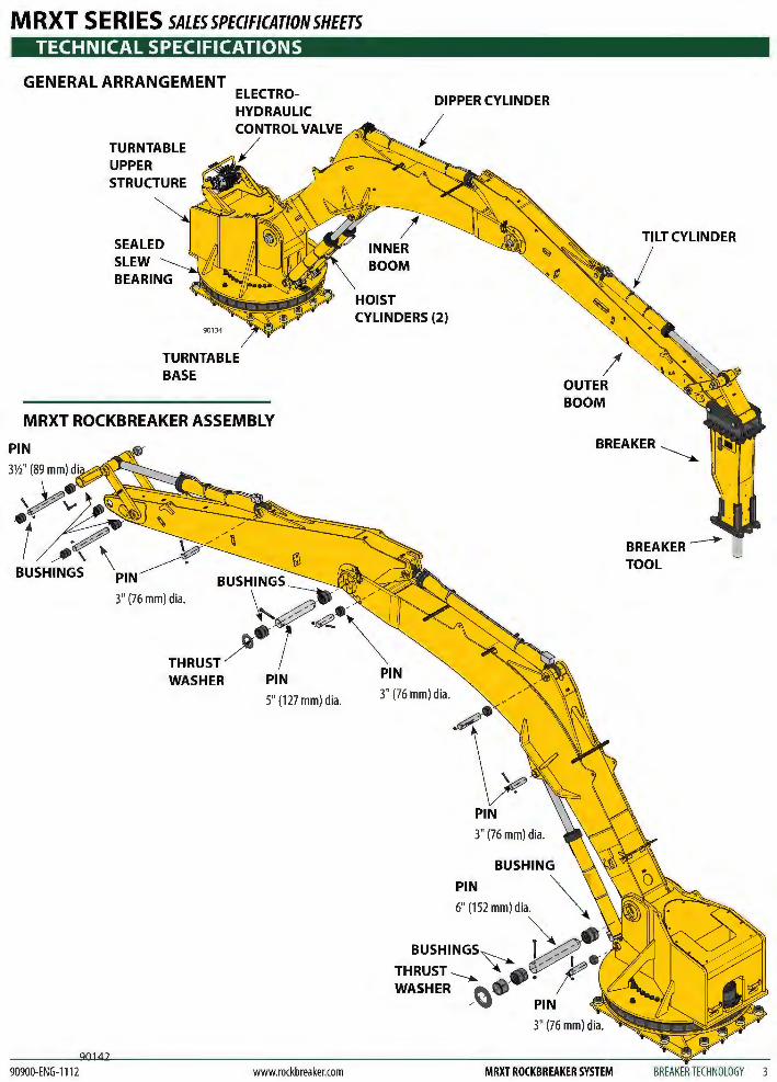
GENERAL ARRANGEMENT
TURNTABLE UPPER STRUCTURE
SLEW
ELECTRO-HYDRAULIC CONTROL VALVE
/
TURNTABLE BASE
MRXT ROCKBREAKER ASSEMBLY
PIN
3" (76 mm) dia.
WASHER PIN
5" (127 mm) dia.
90900-ENG-1112 www.rockbreaker.com
DIPPER CYLINDER
INNER BOOM
HOIST CYLINDERS (2)
3" (76 mm) dia.
PIN
3" (76 mm) dia.
OUTER BOOM
MRXT ROCKBREAKER SYSTEM
TILT CYLINDER
I
BREAKER ___..
TOOL
BREAKER TECHNOLOGY 3
MRXT SERIES SALESSPEC/FICATIONSHEETS TECHNICAL SPECIFICATIONS
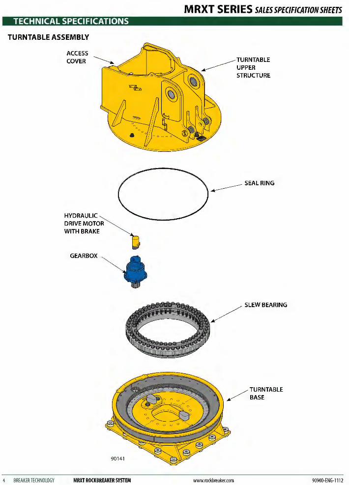
TURNTABLE ASSEMBLY
.--------- SEAL RING
/ SLEW BEARING
/ TURNTABLE / BASE
90141
4 BREAKER TECHNOLOGY MRXT ROCKBREAKER SYSTEM www.rockbreaker.com 90900-ENG-1112
MRXT SERIES SALESSPEC/FICAT/ONSHEETS TECHNICAL SPECIFICATIONS
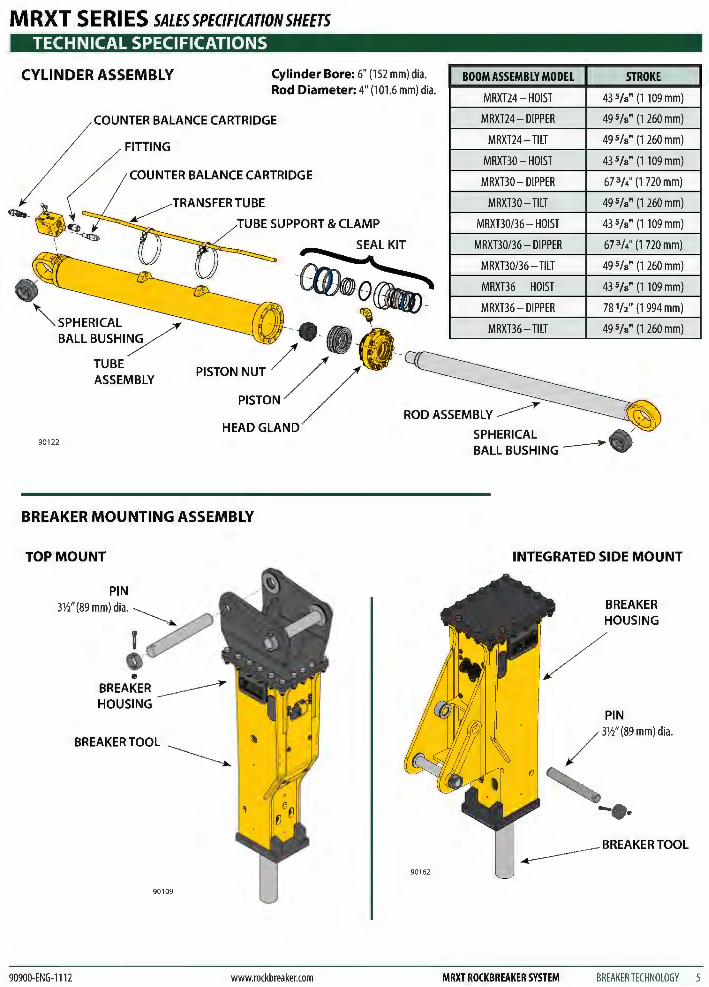
CYLINDER ASSEMBLY Cylinder Bore: 6" (152 mm) dia. Rod Diameter: 4" (101.6 mm) dia.
BOOM ASSEMBLY MODEL
MRXT24- HOIST
STROKE
435/s" (1109 mm)
COUNTER BALANCE CARTRIDGE
FITTING
, / COUNTER BALANCE CARTRIDGE
( ~ TRANSFER TUBE
~~9 ~ TUBESUPPORT&CLAMP .. \ ~
I
~SPHERICAL BALLBUSHIY
90122
TUBE ASSEMBLY
BREAKER MOUNTING ASSEMBLY
TOP MOUNT
PIN 3Yz" (89 mm) dia. ~
v .~
90900-ENG-1112
e BREAKER~ HOUSING
BREAKERTOOL ~
90109
www.rockbreaker.com
MRXT24- DIPPER 49 5/s" (1 260 mm)
MRXT24- TILT 49 5/s" (1 260 mm)
MRXBO- HOIST 43 5/s" (1109 mm)
MRXBO- DIPPER 67 W ' (1 720 mm)
MRXBO- TILT 49 5/s" (1 260 mm)
MRXB0/36- HOIST 43 5/s" (1109 mm)
MRXB0/36- DIPPER 67 W ' (1 720 mm)
MRXB0/36- TILT 49 5/s" (1 260 mm)
MRXT36 HOIST 43 5/s" (1109 mm)
MRXT36- DIPPER 78 W' (1 994 mm)
MRXT36- TILT 49 Sf a" (1 260 mm)
ROD ASSEMBLY~ SPHERICAL
90162
BALL BUSHING ------*
INTEGRATED SIDE MOUNT
BREAKER HOUSING
PIN
/ 3Yz" (89 mm) dia.
0 ~ - .. .-------BREAKER TOOL
MRXT ROCKBREAKER SYSTEM BREAKER TECHNOLOGY 5
M RXT S E Rl ES SALES SPECIFICATION SHEETS TECHNICAL SPECIFICATIONS
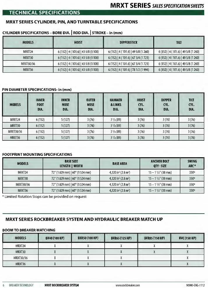
MRXT SERIES CYLINDER, PIN, AND TURNTABLE SPECIFICATIONS
CYLINDER SPECIFICATIONS- BORE DIA.I ROD DIA.I STROKE- in (mm)
MODELS HOIST DIPPERSTICK TILT
MRXT24 6 (152) 14 ( 101.6) 143 5/8 (1108) 6 (152) 14 ( 1 01.6) j49 5/8 (1 260) 6 (152) 14 ( 101.6) 149 5/8 (1 260)
MRXT30 6 (152) 14 ( 101.6) 143 5/8 (1108) 6 (152) 14 ( 101.6) 167 3/4 (1721) 6 (152) 14 ( 101.6) 149 5/8 (1 260)
MRXB0/36 6 (152) 14 ( 101.6) 143 5/8 (1108) 6 (152) 14 ( 101.6) j67 3/4 (1721) 6 (152) 14 ( 101.6) 149 5/8 (1 260)
MRXT36 6 (152) 14 ( 101.6) 143 5/8 (1108) 6 (152) 14 ( 101.6) 1781/2 (1994) 6 (152) 14 ( 101.6) 149 5/8 (1 260)
PIN DIAMETER SPECIFICATIONS- in (mm)
INNER INNER OUTER HAMMER HOIST DIPPER TILT MODELS FOOT NOSE NOSE &LINKS CYL. CYL. CYL.
DIA. DIA. DIA. DIA. DIA. DIA. DIA.
MRXT24 6 (152) 5 (127) 3 (76) 31h (89) 3 (76) 3 (76) 3 (76)
MRXT30 6 (152) 5 (127) 3 (76) 31/2 (89) 3 (76) 3 (76) 3 (76)
MRXB0/36 6 (152) 5 (127) 3 (76) 31/2 (89) 3 (76) 3 (76) 3 (76)
MRXT36 6 (152) 5 (127) 3 (76) 31/2 (89) 3 (76) 3 (76) 3 (76)
FOOTPRINT MOUNTING SPECIFICATIONS
MODELS BASE SIZE
BASE AREA ANCHOR BOLT SWING
LENGTH I WIDTH QTY-SIZE ARC*
MRXT24 72" (1 829 mm) 160" (1 524 mm) 4,320 in2 (2.8 m2) 15 - 1 W' (38 mm) 330°
MRXT30 72" (1 829 mm) 160" (1 524 mm) 4,320 in2 (2.8 m2) 15 - 1 W' (38 mm) 330°
MRXB0/36 72" (1 829 mm) 160" (1 524 mm) 4,320 in2 (2.8 m2) 15 - 1 W' (38 mm) 330°
MRXT36 72" (1 829 mm) 160" (1 524 mm) 4,320 in2 (2.8 m2) 15 - 1 W' (38 mm) 330°
* Limited Rotation Stops can be provided on request
MRXT SERIES ROCKBREAKER SYSTEM AND HYDRAULIC BREAKER MATCH UP
BOOM TO BREAKER MATCHING
MODELS BX40 (100 HP) BXR50 (100 HP) BXR65 (125 HP) BXR85 (150 HP) HVC(150HP)
MRXT24 X X X X X
MRXT30 X X X X X
MRXB0/36 X X X X
MRXT36 X X X X
6 BREAKERTECHNOLOGY MRXT ROCKBREAKER SYSTEM www.rockbreaker.com 90900-ENG-1112

M RXT S E Rl ES SALES SPECIFICATION SHEETS
TECHNICAL SPECIFICATIONS
MRXTSERIES PAYLOAD LIFT CAPACITY
(without breaker)
MRXT36 PAYLOAD LIFT CAPACITY:
6,700 lb (3 039 kg)
MRXT30/36 PAYLOAD LIFT CAPACITY:
6,700 lb (3 039 kg)
PAYLOAD LIFT CAPACITY: 8,000 lb (3 628 kg)
90139
WEIGHT- lb (kg)
MODELS
MRXT24
MRXT30
MRXB0/36
MRXT36
MRXT24 PAYLOAD LIFT CAPACITY:
10,000 lb (4 535 kg)
TURNTABLE INNER BOOM
13,720 (6 223) 5,070 (2 300)
13,720 (6 223) 6,600 ( 2 994)
13,720 (6 223) 7,093 (3 217)
13,720 (6 223) 7,093 (3 217)
BOOM DIMENSIONS- in (mm)
MODELS OUTER BOOM INNER BOOM HEIGHT - WIDTH HEIGHT - WIDTH
MRXT24 30 (762) -17 (432) 26 11;\6 (678)- 27 (686)
MRXBO 31 11!16 (804) -17 (432) 33 (840)- 27 (685)
MRXB0/36 34 5/a (880) -17 (432) 33 (840)- 27 (685)
MRXT36 34 5/a (880) -17 (432) 38 h (977)- 27 (685)
90900-ENG-1112 www.rockbreaker.com
OUTER OVERALL BOOM WEIGHT
3,080 (1 397) 21,870 (9 920)
3,131 (1420) 23,450 (10 637)
3,131 (1420) 23,944 (10 860)
4,085 (2 200) 24,898 (11 294)
PINTO PIN PINTO PIN OUTER BOOM INNER BOOM
139 (3 530) 171 (4 343)
153 (3 886) 196 (4 978)
186 (4 724) 196 (4 978)
186 (4 724) 239 7h6 (6 082)
MRXT ROCKBREAKER SYSTEM BREAKER TECHNOLOGY 7
TECHNICAL SPECIFICATIONS
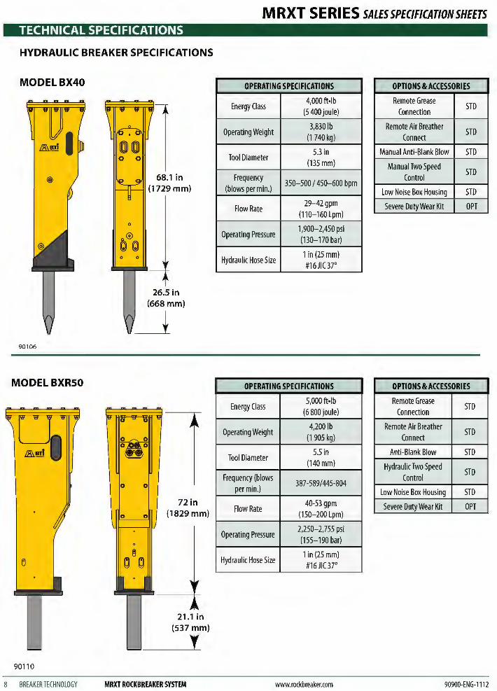
HYDRAULIC BREAKER SPECIFICATIONS
MODELBX40
90106
MODELBXRSO
90110
8 BREAKER TECHNOLOGY
0
0 0
68.1 in (1729 mm)
26.5 in (668mm)
~
0
72in (1829 mm)
MRXT ROCKBREAKER SYSTEM
MRXT SERIES SALESSPEC/FICATIONSHEETS
OPERATING SPECIFICATIONS OPTIONS & ACCESSORIES
Energy Class 4,000ft·lb
(5 400 joule) Remote Grease
STD Connection
Operating Weight 3,830 lb
(1 740 kg) Remote Air Breather
STD Connect
Tool Diameter 5.3 in
(135mm)
Frequency 350-500 I 450-600 bpm
(blows per min.)
Manual Anti-Blank Blow STD
Manual Two Speed STD
Control
Low Noise Box Housing STD
Flow Rate 29-42gpm
(110-160Lpm) Severe Duty Wear Kit OPT
Operating Pressure 1,900-2,450 psi (130-170 bar)
Hydraulic Hose Size 1 in (25 mm) #16JIC3r
OPERATING SPECIFICATIONS OPTIONS & ACCESSORIES
Energy Class 5,000 ft·lb
(6 800 joule) Remote Grease
STD Connection
Operating Weight 4,200 lb
(1 905 kg) Remote Air Breather
STD Connect
Tool Diameter 5.5 in
(140mm)
Frequency (blows 387-589/445-804
per min.)
Anti-Blank Blow STD
Hydraulic Two Speed STD
Control
Low Noise Box Housing STD
Flow Rate 40-53 gpm
(150-200 Lpm) Severe Duty Wear Kit OPT
Operating Pressure 2,250-2,755 psi (155-190 bar)
Hydraulic Hose Size 1 in (25 mm) #16JIC3r
www.rockbreaker.com 90900-ENG-1112
M RXT S E Rl ES SALES SPECIFICATION SHEETS TECHNICAL SPECIFICATIONS
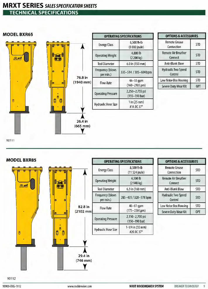
MODELBXR65
90111
MODEL BXR85
" e
90112
76.8 in (1940 mm)
26.4 in (665 mm)
I
82.8 in (2102 mm
29.4 in (746mm)
I
OPERATING SPECIFICATIONS
Energy Class 6,500 ft·lb
(8 800 joule)
Operating Weight 4,880 lb
(2 200 kg)
Tool Diameter 6.0 in (150 mm)
Frequency (blows 335-514 I 385-684 bpm
per min.)
Flow Rate 46-55gpm
(160-210 Lpm)
Operating Pressure 2,250-2,755 psi (155-190 bar)
Hydraulic Hose Size 1 in (25 mm) #16JIC3r
OPERATING SPECIFICATIONS
Energy Class 8,500 ft·lb
(11 524 joule)
Operating Weight 6,500 lb
(2 948 kg)
Tool Diameter 6.3 in (160 mm)
Frequency (blows 285-435 I 328-578 bpm
per min.)
Flow Rate 46-61 gpm
(175-230 Lpm)
Operating Pressure 2,150-2,700 psi (150-190 bar)
Hydraulic Hose Size 1-114 in (32 mm)
#20 JIC 3r
OPTIONS & ACCESSORIES
Remote Grease STD
Connection
Remote Air Breather STD
Connect
Anti-Blank Blow STD
Hydraulic Two Speed STD
Control
Low Noise Box Housing STD
Severe Duty Wear Kit OPT
OPTIONS & ACCESSORIES
Remote Grease STD
Connection
Remote Air Breather STD
Connect
Anti-Blank Blow STD
Hydraulic Two Speed STD
Control
Low Noise Box Housing STD
Severe Duty Wear Kit OPT
90900-ENG-ll12 www.rockbreaker.com MRXT ROCKBREAKER SYSTEM BREAKERTECHNOLOGY 9
MRXT APPLICATIONS
ABOVE-GROUND GYRATORY
901 21
GRIZZLY
BREAKER COVERAGE
MAXIMUM } BREAKER
COVERAGE
MRXT SERIES SALESSPEC/FICATIONSHEETS
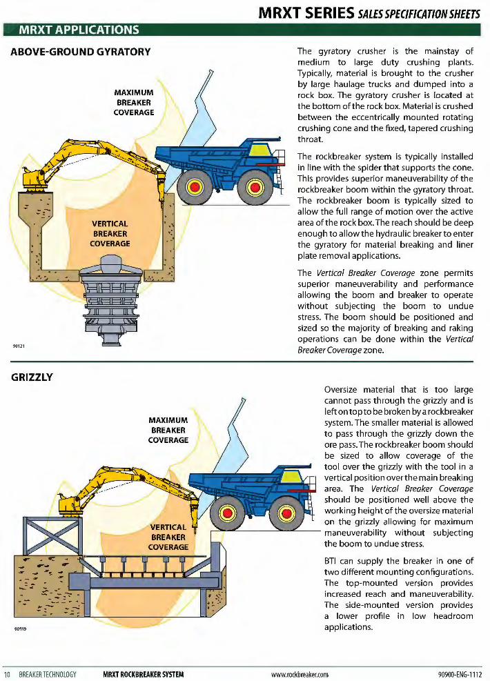
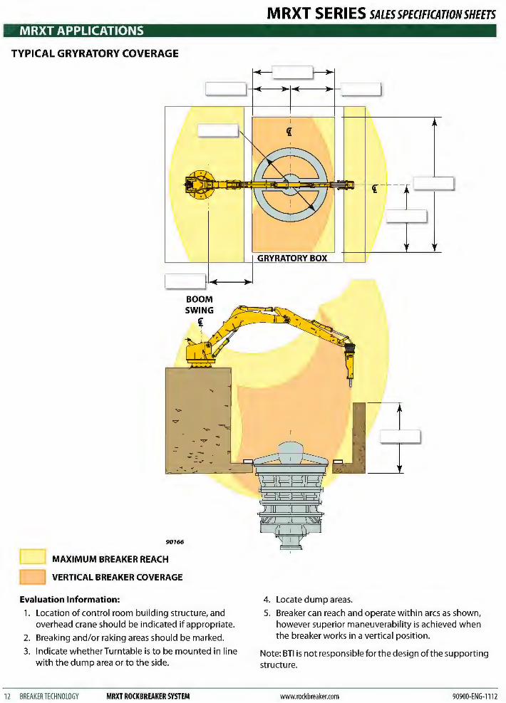
The gyratory crusher is the mainstay of medium to large duty crushing plants. Typically, material is brought to the crusher by large haulage trucks and dumped into a rock box. The gyratory crusher is located at the bottom of the rock box. Material is crushed between the eccentrically mounted rotating crushing cone and the fixed, tapered crushing throat.
The rockbreaker system is typically installed in line with the spider that supports the cone. This provides superior maneuverability of the rockbreaker boom within the gyratory throat. The rockbreaker boom is typically sized to allow the full range of motion over the active area of the rock box. The reach should be deep enough to allow the hydraulic breaker to enter the gyratory for material breaking and liner plate removal applications.
The Vertical Breaker Coverage zone permits superior maneuverability and performance allowing the boom and breaker to operate without subjecting the boom to undue stress. The boom should be positioned and sized so the majority of breaking and raking operations can be done within the Vertical Breaker Coverage zone.
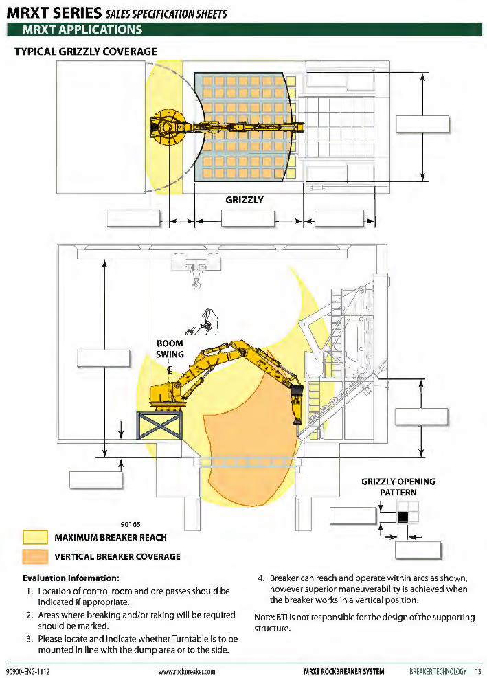
Oversize material that is too large cannot pass through the grizzly and is Iefton top to be broken by a rockbreaker system. The smaller material is allowed to pass through the grizzly down the ore pass. The rockbreaker boom should be sized to allow coverage of the tool over the grizzly with the tool in a vertical position over the main breaking area. The Vertical Breaker Coverage should be positioned well above the working height of the oversize material on the grizzly allowing for maximum
r .,.._..""'----"""""="""'"---- maneuverability without subjecting
... .... .... -:. . - ..,.
._=.: : -~ .. -:: :-: .. .. - _ ... - .....
90119
.... --: -.-----
10 BREAKERTECHNOLOGY MRXT ROCKBREAKER SYSTEM
the boom to undue stress.
BTl can supply the breaker in one of two different mounting configurations . The top-mounted version provides increased reach and maneuverability . The side-mounted version provides a lower profile in low headroom applications.
www.rockbreaker.com 90900-ENG-1112
M RXT S E Rl ES SALES SPECIFICATION SHEETS MRXT APPLICATIONS
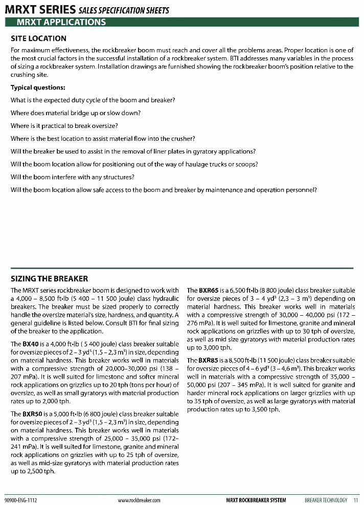
SITE LOCATION For maximum effectiveness, the rockbreaker boom must reach and cover all the problems areas. Proper location is one of the most crucial factors in the successful installation of a rockbreaker system. BTl addresses many variables in the process of sizing a rockbreaker system. Installation drawings are furnished showing the rockbreaker boom's position relative to the crushing site.
Typical questions:
What is the expected duty cycle of the boom and breaker?
Where does material bridge up or slow down?
Where is it practical to break oversize?
Where is the best location to assist material flow into the crusher?
Will the breaker be used to assist in the removal of liner plates in gyratory applications?
Will the boom location allow for positioning out of the way of haulage trucks or scoops?
Will the boom interfere with any structures?
Will the boom location allow safe access to the boom and breaker by maintenance and operation personnel?
SIZING THE BREAKER The MRXT series rockbreaker boom is designed to work with a 4,000 - 8,500 ft·lb (5 400 - 11 500 joule) class hydraulic breakers. The breaker must be sized properly to correctly handle the oversize material's size, hardness, and quantity. A general guideline is listed below. Consult BTl for final sizing of the breaker to the application .
The BX40 is a 4,000 ft·lb ( 5 400 joule) class breaker suitable for oversize pieces of 2-3 yd 3 (1,5- 2,3 m3
) in size, depending on material hardness. This breaker works well in materials with a compressive strength of 20,000-30,000 psi (138 -207 mPa). It is well suited for limestone and softer mineral rock applications on grizzlies up to 20 tph (tons per hour) of oversize, as well as small gyratorys with material production rates up to 2,000 tph.
The BXRSO is a 5,000 ft·lb (6 800 joule) class breaker suitable for oversize pieces of2- 3 yd3 (1,5- 2,3 m3) in size, depending on material hardness. This breaker works well in materials with a compressive strength of 25,000 - 35,000 psi (172-241 mPa). It is well suited for limestone, granite and mineral rock applications on grizzlies with up to 25 tph of oversize, as well as mid-size gyratorys with material production rates up to 2,500 tph.
90900-ENG-1112 www.rockbreaker.com
The BXR65 is a 6,500 ft·lb (8 800 joule) class breaker suitable for oversize pieces of 3 - 4 yd3 (2,3 - 3 m3) depending on material hardness. This breaker works well in materials with a compressive strength of 30,000 - 40,000 psi (172 -276 mPa). It is well suited for limestone, granite and mineral rock applications on grizzlies with up to 30 tph of oversize, as well as mid size gyratorys with material production rates up to 3,000 tph.
The BXR85 is a 8,500ft·lb (11 500 joule) class breaker suitable for oversize pieces of 4-6 yd 3 (3- 4,6 m3
). This breaker works well in materials with a compressive strength of 35,000 -50,000 psi (207 - 345 mPa). It is well suited for granite and harder mineral rock applications on larger grizzlies with up to 35 tph of oversize, as well as large gyratorys with material production rates up to 3,500 tph.
MRXT ROCKBREAKER SYSTEM BREAKER TECHNOLOGY 11
MRXT APPLICATIONS
TYPICAL GRYRATORY COVERAGE
MAXIMUM BREAKER REACH
VERTICAL BREAKER COVERAGE
Evaluation Information:
BOOM
1. Location of control room building structure, and overhead crane should be indicated if appropriate.
2. Breaking and/or raking areas should be marked.
3. Indicate whether Turntable is to be mounted in line with the dump area or to the side.
12 BREAKERTECHNOLOGY MRXT ROCKBREAKER SYSTEM
MRXT SERIES SALESSPEC/FICATIONSHEETS
GRYRATORY BOX
4. Locate dump areas.
5. Breaker can reach and operate within arcs as shown, however superior maneuverability is achieved when the breaker works in a vertical position.
Note: BTl is not responsible for the design of the supporting structure.
www.rockbreaker.com 90900-ENG-1112
MRXT SERIES SALESSPEC/FICAT/ONSHEETS MRXT APPLICATIONS
TYPICAL GRIZZLY COVERAGE
-r-
GRIZZLY
BOOM
90165
MAXIMUM BREAKER REACH
VERTICAL BREAKER COVERAGE
Evaluation Information:
1. Location of control room and ore passes should be indicated if appropriate.
2. Areas where breaking and/or raking will be required should be marked.
3. Please locate and indicate whether Turntable is to be mounted in line with the dump area or to the side.
90900-ENG-1112 www.rockbreaker.com
4. Breaker can reach and operate within arcs as shown, however superior maneuverability is achieved when the breaker works in a vertical position.
Note: BTl is not responsible for the design ofthe supporting structure.
MRXT ROCKBREAKER SYSTEM BREAKER TECHNOLOGY 13
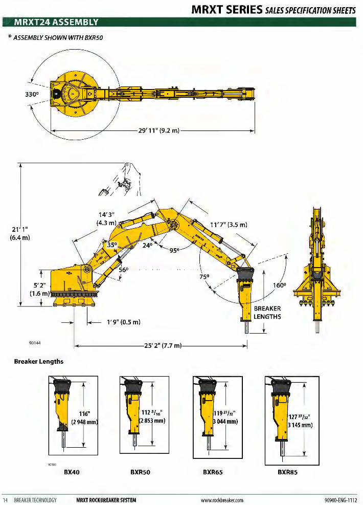
MRXT24 ASSEMBLY
* ASSEMBLY SHOWN WITH BXR50
330°
21' 1" m)
MRXT SERIES SALESSPEC/FICATIONSHEETS
LENGTHS 1'9" (0.5 m)
90144 ~-------25' 2" (7.7 m)----------+1
Breaker Lengths
116"
'~ 90103
BX40 BXRSO BXR65 BXR85
14 BREAKER TECHNOLOGY MRXT ROCKBREAKER SYSTEM www.rockbreaker.com 90900-ENG-1112
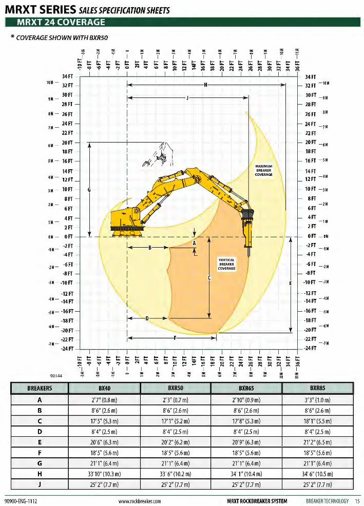
MRXT SERIES SALESSPEC/FICAT/ONSHEETS MRXT 24 COVERAGE
* COVERAGE SHOWN WITH BXR50
::e ::e ::e ::e ::e ::e ::e ::e ::e ::e :::::IE ::e :E :E
..} T T T T I iT iI i i TT ~ ~ ~ ~ ~ ~ ~ ~ ~ ~ ~ ~ ~ ~ ~ ~ ~ ~ ~ ~ ~ ~ - ~ ~ ~ ~ Q N ~ ~ = ~ ~ ~ ~ ~ ~ ~ ~ ~ ~ ~I ~
34 FT - r--1 ___._____._.___--'--_,_---'------'-"'---'----'-------'-'---'----"----'------'------'-----i- 34 FT
10M - 32FT
30FT 9M -
28FT
8M - 26FT
24FT 7M -
22FT -
6M_ 20FT
18FT
SM - 16FT
14FT -4M - 12FT
JM - lOFT - G
8FT 2M -
4FT 1M -
2FT
OM - 0 FT
-2FT -·1M -
-4FT
·2M - ·6FT -
-8FT
I
__ /; ~-______ j 1-~mm-
BREAKER COVERAGE
32FT - 10M
- 30FT _ 9M
28FT
- 26FT - SM
24FT - JM
- 22FT
20FT _ 6M
18FT
16FT - SM
- 14FT 12FT - 4M
- lOFT - JM
8FT - 2M
6FT
4FT - 1M
2FT
0 FT - OM
-2FT - -1M -4FT
-6FT - -2M
-8FT
~2FT ~2FT
·3M - -10FT - u ( •4M- -14FT - - -14FT - -4M
-SM - -16FT I -16FT - -SM
-18FT - ~D----+< - -18FT ·6M - - ·6M
~FT ~FT
~FT ~FT -JM - - -7M
-24 FT --L.---,----,-,.-.,...-,-----r---r-.,...--r----r-----r---,---,---,.---,------,----l- -24 FT
t::t:t:t:t:t::: t:: t: t:: t: t: OCO~"r'":'IO '71 , I I
N-.::t\0000
1-I I "' "' "" "' "' "' 90144
.... .... ... ... N ~ - -I
"' -.... .... .... ... ... ... \C) 00 C>
1 - r--.... .... .... ... ... ... N ~ \C N N N
I I
"' "' ~ =
........ ...... 00 C> N M
I "' ~
.... .... .... ... ... ... N ~ \C .., .., ..,
I I
"' "' ~
BREAKERS BX40 BXRSO BXR65 BXR85
A 2' 7" (0.8m) 2'3" (0.7 m) 2' 1 0" (0.9 m) 3' 3" (1.0 m)
B 8'6" (2.6m) 8'6" (2.6m) 8'6" (2.6 m) 8'6" (2.6m)
c 17' 5" (5.3 m) 17'1" (5.2 m) 17' 8" (5.3 m) 18'1'' (5.5 m)
D 8'4" (2.5 m) 8'4" (2.5 m) 8'4" (2.5 m) 8'4" (2.5 m)
E 20'6" (6.3 m) 20'2" (6.2 m) 20'9" (6.3 m) 21'2" (6.5 m)
F 18' 5" (5.6 m) 18' 5" (5.6 m) 18' 5" (5.6 m) 18' 5" (5.6 m)
G 21 ' 1" (6.4m) 21'1" (6.4m) 21'1" (6.4m) 21'1" (6.4m)
H 33'10" (10.3 m) 33' 6" (10.2 m) 34' 1" (10.4 m) 34' 6" (10.5 m)
J 25' 2" (7 .7 m) 25' 2" (7.7 m) 25' 2" (7.7 m) 25' 2" (7 .7 m)
90900-ENG-1112 www.rockbreaker.com MRXT ROCKBREAKER SYSTEM BREAKERTECHNOLOGY 15
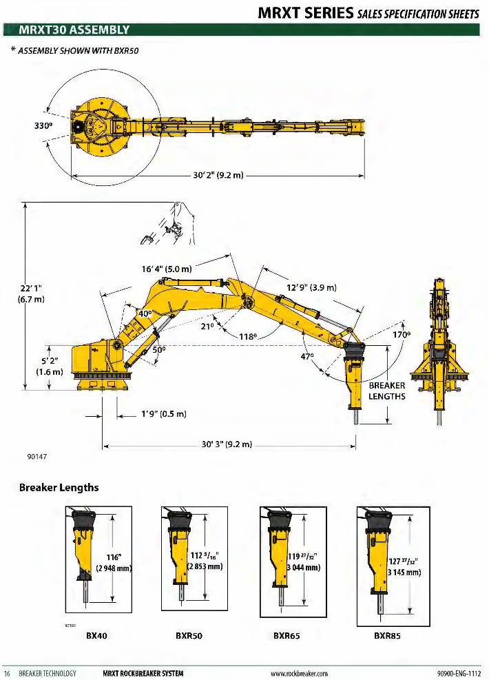
MRXT30 ASSEMBLY
* ASSEMBLY SHOWN WITH BXR50
330°
22' 1" 7m)
90147
Breaker Lengths
116"
'~ 90103
BX40 BXRSO
16 BREAKERTECHNOLOGY MRXT ROCKBREAKER SYSTEM
MRXT SERIES SALESSPEC/FICATIONSHEETS
BXR65 BXR85
www.rockbreaker.com 90900-ENG-1112
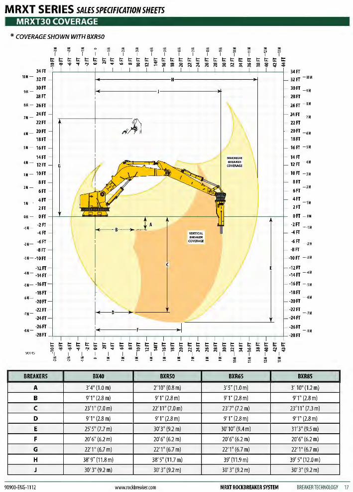
MRXT SERIES SALESSPEC/FICAT/ONSHEETS MRXT30 COVERAGE
* COVERAGE SHOWN WITH BXR50
'"' '"' '"' '"' '"' '"' '"' '"' '"' '"' '"' '"' '"' '"' '"' '"' T T T T I T i I T T i i T T T f t:: t:: t:: t:: t:: t:: t:: t:: t:: t:: t:: t::
34FT 34FT 10M - 32FT 32FT - 10M
30FT 30FT - 9M 9M -28FT 28FT
aM - 26FT 26FT - aM
24FT 24FT 7M - - 7M
22FT If~ 22FT
6M - 20FT 20FT - 6M
18FT 18FT
SM - 16FT 16FT - SM
14FT 14FT 4M - 12FT
BREAKER 12FT - 4M COVERAGE
JM - 10FT 10FT - JM
8FT 8FT 2M - - 2M
6FT 6FT
4FT 4FT 1M - - 1M
2FT 2FT
OM - OFT 0 FT - OM
-1M --2FT -2FT
- -1M
-4FT VERTICAL -4FT BREAKER
-6FT COVERAGE -2M -
-6FT --2M
-8FT -8FT
-JM- -10FT -10FT - -JM
-12FT -12FT -4M - -14FT -14FT - -4M
-sM - -16FT -16FT - -sM
-18FT -18FT -6M - --6M
-20FT -20FT
-22FT -22FT -7M - - -7M
-24FT -24FT
-26FT -26FT -aM - - -aM
-28FT -28FT
t:: t:: t:: t:: t:: t:: t:: t:: t:: t:: t:: t:: t:: t:: t:: t:: t:: t:: t:: t:: t:: t:: t:: t:: t:: t:: c:> Of' ~ "'t ":' c:> N .... 00 c:> ~ ;!: ... 00 c:> N .... ... 00 c:> N .... ... 00 c:> N .... '71 1- I - N N N N N .... .... .... .... .... .... .... I .... 90145 I I I I I I I I I I I I
'"' '"' '"' ~ ~ ::; ~ :; :; ~ :;; ;;; '"' '"' '"' '"' "" "' .,-
BREAKERS BX40 BXRSO BXR65 BXR85
A 3'4" (1.0m) 2' 1 0" (0.8 m) 3' 5" (1.0 m) 3' 10" (1 .2 m)
B 9'1" (2.8m) 9'1" (2.8m) 9' 1" (2.8 m) 9'1" (2.8m)
c 23' 1" (7.0 m) 22' 11" (7.0 m) 23'7" (7 .2 m) 23' 11" (7.3 m)
D 9'1" (2.8m) 9' 1" (2.8 m) 9' 1" (2.8 m) 9' 1" (2.8m)
E 25' 5" (7.7 m) 30' 3" (9.2 m) 30' 1 0" (9.4 m) 31 '3" (9.5 m)
F 20' 6" (6.2 m) 20' 6" (6.2 m) 20' 6" (6.2 m) 20'6" (6.2 m)
G 22' 1"(6.7m) 22' 1" (6.7 m) 22' 1" (6.7 m) 22' 1" (6.7 m)
H 38' 9" (11 .8 m) 38' 5" (11.7 m) 39' (11 .9 m) 39' 5" (12.0 m)
J 30' 3" (9.2 m) 30' 3" (9.2 m) 30' 3" (9.2 m) 30' 3" (9.2 m)
90900-ENG-1112 www.rockbreaker.com MRXT ROCKBREAKER SYSTEM BREAKER TECHNOLOGY 17
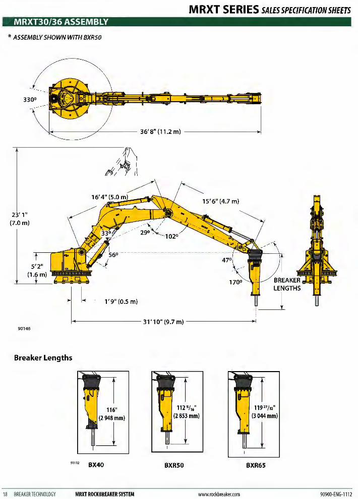
MRXT30/36 ASSEMBLY
* ASSEMBLY SHOWN WITH BXRSO
330°
23' 1" (7.0 m)
1'9" (0.5 m)
MRXT SERIES SALESSPEC/FICATIONSHEETS
15' 6" (4.7 m)
~------- 31' 10" (9.7 m) -------+1 90146
Breaker Lengths
116" (2948mm)
90102 BX40
18 BREAKERTECHNOLOGY MRXT ROCKBREAKER SYSTEM
BXRSO BXR65
www.rockbreaker.com 90900-ENG-1112
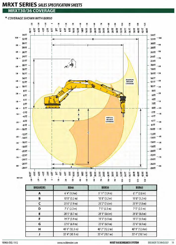
MRXT SERIES SALESSPEC/FICAT/ONSHEETS MRXT30/36 COVERAGE
* COVERAGE SHOWN WITH BXR50
"' "' "' "' "' "' "' "' "' "' "' "' "' "' "' "' T T T I T i i T i T i I T T T f t: t: .... .... t: t: t: t: t: t: t: t: t: t: t: t: t: t: t: t: t: t: t: t: t: .... ... ... ... :: Of' 'I' "r ":' 0 N .... "' co :: :::! ;! :2 co 0 N .... "' co N "' co 0 N ::;!: - N N N N N .... .... .... .... ....
34FT 34FT 10M - 3lFT 32FT - 10M
30FT 30FT - 9M 9M -28FT 28FT
BM - 26FT 26FT - BM
24FT 24FT - 7M 7M -22FT
~:~ 22FT
6M - 20FT 20FT _ 6M
18FT 18FT
SM - 16FT 16FT - SM
14FT 14FT 4M- 12FT 12FT - 4M
3M - 10FT 10FT - JM
8FT 8FT 2M - - 2M
6FT
l 6FT
4FT 4FT 1M - - 1M
2FT 2FT ---/--OM - OFT 0 FT - OM
-2FT -2FT ·1M - --1M
-4FT -4FT VERTICAL
-6FT BREAKER -6FT ·2M - COVERAGE --2M
-8FT -8FT
·lM - -10FT -lOFT - -lM
-12FT -12FT ·4M - -14FT -14FT - -4M
-SM - -16FT -16FT - -sM
-18FT -18FT -6M - - -6M
-20FT -20FT
-22FT -22FT ·7M - - -7M
-24FT -24FT
-26FT -26FT ·BM - - -sM
-28FT -28FT
t: t: t: t: .... t: t: t: t: t: t: t: t: t: t: t: t: t: t: t: t: t: t: t: t: t: t: t: ... 0 Of' 'I' "r ":' 0 N .... "' co 0 :::! ;! "' ~ 0 N .... "' co 0 N .... "' co 0 N .... o;-1 1- 'T N N N N N .... .... .... .... .... .... .... I ....
90149 I I I I I I I I I I I I "' "' "' ~ ;:;; ;::; ~ ;:'; ::; ;:;: ~ ~ "' "' "' "' "" "' 0
BREAKERS BX40 BXRSO BXR65
A 6' 4" (1.9 m) 5' 11" (1 .9 m) 6' 7" (2.0 m)
B 10'8" (3 .2 m) 1 0'8" (3.2 m) 1 0'8" (3.2 m)
c 25' 6" (7.9 m) 25'2" (7.6 m) 25' 9" (7.8 m)
D 7' 5" (2.3 m) 7' 5" (2.3 m) 7' 5" (2.3 m)
E 28' 5" (8.7 m) 28' 1" (8.6 m) 28' 8" (8.8 m)
F 19'3"(5.9m) 19'3" (5.9 m) 19'3" (5.9 m)
G 22' 6" (6.9 m) 22' 6" (6.9 m) 22' 6" (6.9 m)
H 40' 6" (12.3 m) 40' 2" (12.2 m) 40' 9" (12.4 m)
J 33' 4" (10.1 m) 33' 4" (10.1 m) 33' 4" (10.1 m)
90900-ENG-1112 www.rockbreaker.com MRXT ROCKBREAKER SYSTEM BREAKERTECHNOLOGY 19
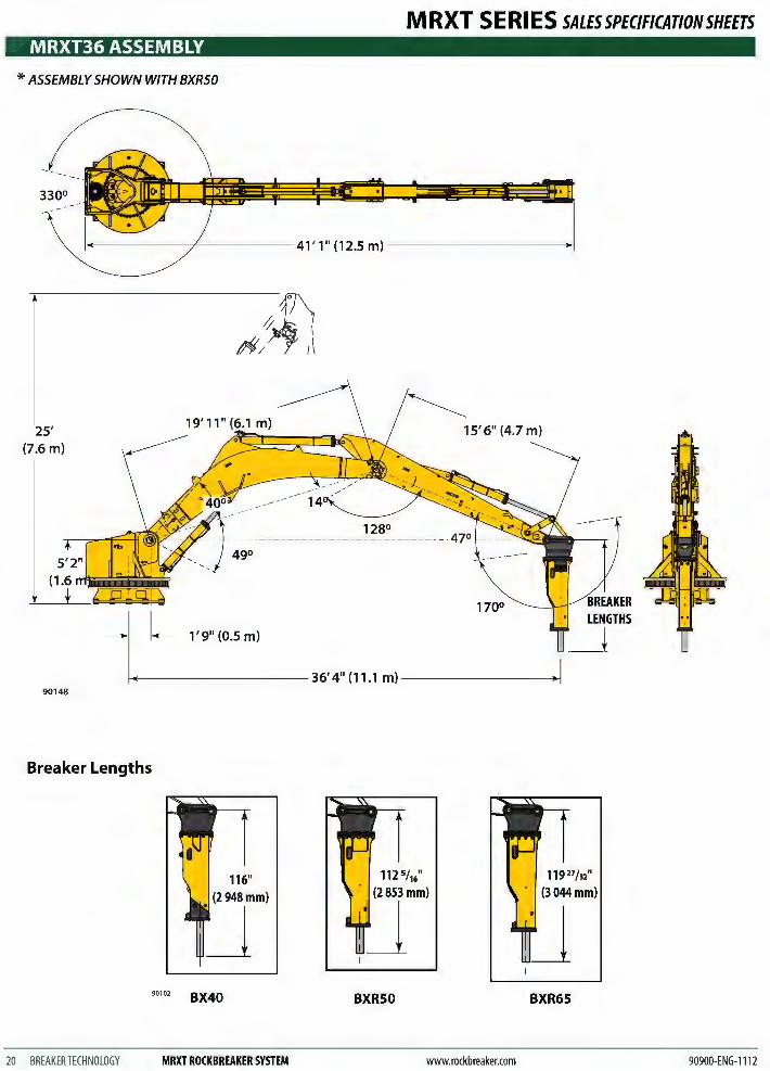
MRXT36 ASSEMBLY
* ASSEMBLY SHOWN WITH BXR50
330°
25' (7.6 m)
90148
Breaker Lengths
20 BREAKER TECHNOLOGY
90102
116" (2948mm)
BX40
MRXT ROCKBREAKER SYSTEM
MRXT SERIES SALESSPEC/FICATIONSHEETS
15' 6" (4.7 m)
BXR50 BXR65
www.rockbreaker.com 90900-ENG-1112
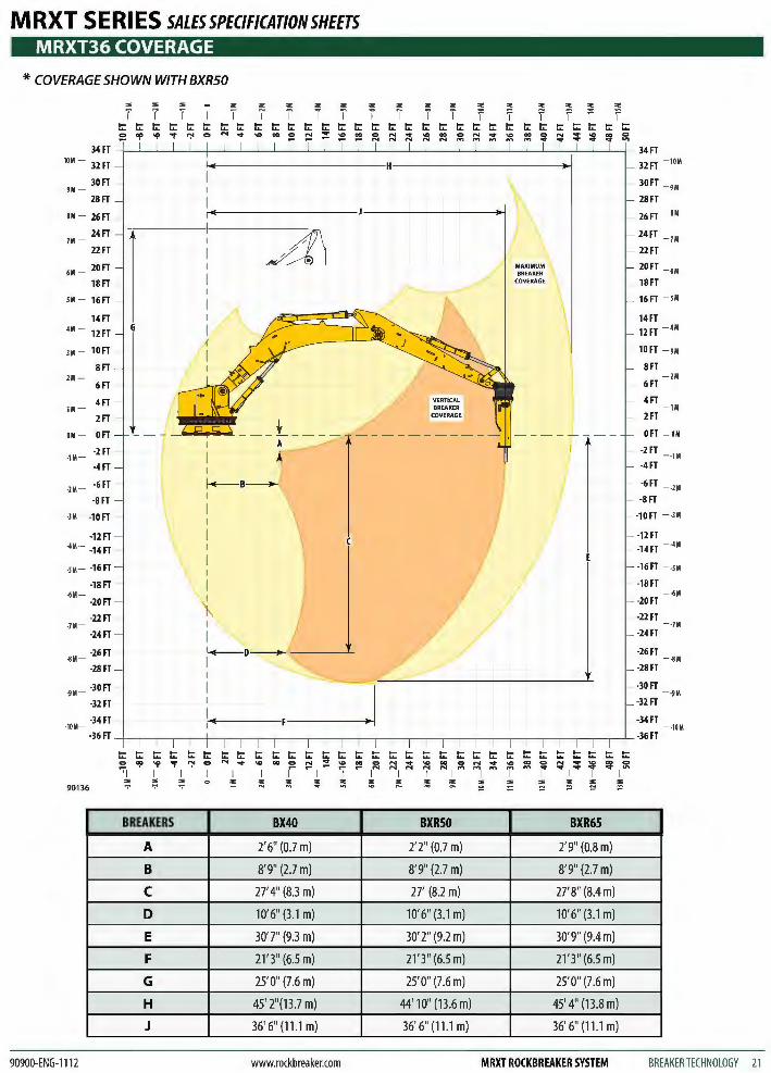
MRXT SERIES SALESSPEC/FICAT/ONSHEETS MRXT36 COVERAGE
* COVERAGE SHOWN WITH BXR50
,. "' "' ,. ,. ,.
"' "' "' "' ,. ,. ,. ,. ,.
"' ,.
"' T T T T T T i T r T I I 1' 'I l' f 'f f t;: t;: t;: t;: t;: t;: t;: t;: t;: t;: ..... t;: t;: t;: t;: t;: ..... ..... t;: t;: t;: t;: t;: t;: t;: t;: ~ ~ ~
:: "!' ~ "r ':' 0 N ... "' 00 :: :::! ;!: "' 0 :::: ... "' 00 :::: ~ ~ :; ~ ~ ~ N N N N
34FT 34FT 10M - 32FT 32FT - 10M
30FT 30FT - 9M 9M -28FT 28FT
8M - 26FT - - 26FT - SM
24FT
AI 24FT - 7M 7M -22FT - 22FT
20FT MAXIMUM 20FT 6M -
~ BREAKER - 6M
18FT COVERAGE - 18FT
SM - 16FT 16FT - SM
14FT 14FT 4M- 12FT G 12FT - 4M
lM - lOFT lOFT - JM
8FT 8FT 2M - - 2M
6FT 6FT
4FT 4FT 1M -
__ j - 1M
2FT 2FT
OM - OFT 0 FT - OM
·1M --2FT -2FT
--1M
-4FT -4 FT
·2M --6FT - -6FT - -2M
-8FT -8FT
·lM - -10FT - -lOFT - -lM
-12FT -12FT ·4M - -14FT -1 4FT - ·4M
-sM - -16FT -16FT - -SM
-18FT - - -18FT -6M - - -6M
-20FT -20FT
-22FT -22FT ·7M - - -7M
-24FT -24FT
-26FT -26FT ·SM - --SM
-28FT -28FT
-30FT -30FT ·9M - - -9M
-32FT -32FT
-34FT - -34FT ·10M- - -10M
-36FT -36FT
t;: t;: t;: t;: t;: t;: t;: t;: t;: t;: t;: t;: t;: t;: t;: t;: t;: t;: t;: t;: t;: t;: t;: t;: t;: t;: t;: t;: t;: t;: t;: 0 "!' ~ "r N 0 N ... "' 00 0 :::! ;!: "' 00 0 N ... "' 00 :;: N ~ "' 00 0 N :; ~ ~ ~ ":"I I~ I ~ N N N N N
"'I T .... ... ... I I I I I I I I I I I I I
"' ~ "' ;'!: :'!; ;:'; '!' ~ ~ ;'!; ! ;; ::i "' "' ,.
"' ,.
90136
BREAKERS BX40 BXRSO BXR65
A 2'6" (0.7 m) 2'2" (0.7 m) 2'9" (0.8 m)
B 8'9" (2.7 m) 8'9" (2.7 m) 8'9" (2.7 m)
c 27' 4" (8.3 m) 27' (8.2 m) 27' 8" (8.4 m)
D 10'6" (3 .1 m) 10'6" (3.1 m) 10'6" (3.1 m)
E 30'7" (9.3 m) 30'2" (9.2 m) 30'9" (9.4 m)
F 21' 3" (6.5 m) 21'3" (6.5 m) 21'3" (6.5 m)
G 25'0" (7.6 m) 25'0" (7.6 m) 25'0" (7.6 m)
H 45' 2"(13.7 m) 44' 10" (13.6 m) 45' 4" (13.8 m)
J 36' 6" (11.1 m) 36'6" (11 .1 m) 36' 6" (11 .1 m)
90900-ENG-1112 www.rockbreaker.com MRXT ROCKBREAKER SYSTEM BREAKERTECHNOLOGY 21
MRXT SERIES SALESSPEC/FICATIONSHEETS INSTALLATION
TYPICAL ROCKBREAKER SYSTEM & OPTIONS BTl rockbreaker systems are shipped un-assembled. The following items are included with each shipment:
• Turntable (locate system serial number on rear side)
• Electric Hydraulic Power Pack
• Hydraulic Breaker (if breaker is not to be installed right away, store indoors standing up)
• Outer Boom (Dipperstick Boom), with Tilt Cylinder installed
• Inner Boom, with Dipperstick Cylinder installed
• Hoist Cylinder
• Hydraulic hoses, tubes, options, and any spare parts will be crated separately.
BTl turntable mounted rockbreaker booms are installed on two different types of sub-structure-structural steel and reinforced concrete. BTl can suggest configurations, however customers must determine which is appropriate.
Threaded Tie Rods must be within 1/8" (3 mm) tolerance of dimensions shown on installation diagrams. They should be torqued in a lubricated condition to 1,460 ft·lb (1 980 N·m).
Nylon Mounts sandwiched between the turntable base and substructure help absorb the transmission of shock from the boom to the support structure.
Shims -1/8" and 1/4" (3 mm and 6 mm) supplied with the bolt kit, eliminate irregularities between the two surfaces.
MRXT SITE PREPARATION
22 BREAKER TECHNOLOGY MRXT ROCKBREAKER SYSTEM
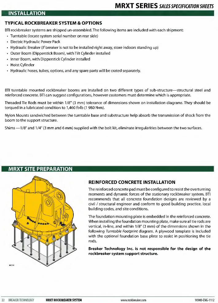
REINFORCED CONCRETE INSTALLATION The reinforced concrete pad must be configured to resist the overturning moments and dynamic forces of the stationary rockbreaker system. BTl recommends that all concrete foundation designs are reviewed by a civil I structural engineer and conform to good building practice, local building codes, and site conditions.
The foundation mounting plate is embedded in the reinforced concrete. When installing the foundation mounting plate, make sure all tie rods are vertical, in-line, and within 1 /8" (3 mm) of the dimensions shown in the following Turntable Footprint diagram. A plywood template is included with the optional foundation base plate to assist in positioning the tie rods.
Breaker Technology Inc. is not responsible for the design of the rockbreaker system support structure.
www.rockbreaker.com 90900-ENG-1112
M RXT S E Rl ES SALES SPECIFICATION SHEETS MRXT SITE PREPARATION
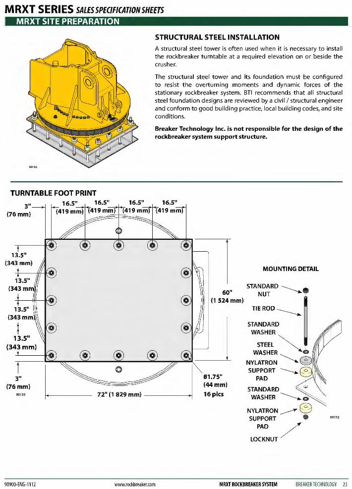
TURNTABLE FOOT PRINT
(76 mm)
STRUCTURAL STEEL INSTALLATION
A structural steel tower is often used when it is necessary to install the rockbreaker turntable at a required elevation on or beside the crusher.
The structural steel tower and its foundation must be configured to resist the overturning moments and dynamic forces of the stationary rockbreaker system. BTl recommends that all structural steel foundation designs are reviewed by a civil I structural engineer and conform to good building practice, local building codes, and site conditions.
Breaker Technology Inc. is not responsible for the design of the rockbreaker system support structure.
3"l ~~~--~------~----~~--~~~
@
@ @ 0
3" (76mm)
90133 72" (1 829 mm) -----~
90900-ENG-1112 www.rockbreaker.com
MOUNTING DETAIL
STANDARD -----60" NUT --......
(1 524mm)
16 pies
TIE ROD~
STANDARD
STANDARD WASHER~
NYLATRON~® SUPPORT
PAD /
LOCKNUT
90132
MRXT ROCKBREAKER SYSTEM BREAKER TECHNOLOGY 23
INSTALLATION
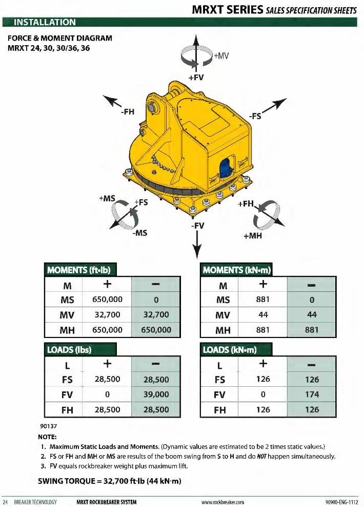
FORCE & MOMENT DIAGRAM MRXT 24, 30, 30/36, 36
~ -FH
MOMENTS (ft•lb)
M MS MV MH
LOADS(Ibs)
90137
NOTE:
L
FS FV FH
+ 650,000
32,700
650,000
+ 28,500
0
28,500
-0
32,700
650,000
-28,500
39,000
28,500
MRXT SERIES SALESSPEC/FICATIONSHEETS
+MV
+FV
-FV
t +MH
MOMENTS (kN•m)
M + -MS 881 0
MV 44 44
MH 881 881
LOADS (kN•m)
L + -FS 126 126
FV 0 174
FH 126 126
1. Maximum Static Loads and Moments. (Dynamic values are estimated to be 2 times static values.)
2. FS or FH and MH or MS are results of the boom swing from S to H and do NOT happen simultaneously.
3. FV equals rockbreaker weight plus maximum lift.
SWING TORQUE= 32,700 fHb (44 kN·m)
24 BREAKER TECHNOLOGY MRXT ROCKBREAKER SYSTEM www.rockbreaker.com 90900-ENG-1112
MRXT SERIES SALESSPECIFICATIONSHEETS MRXT SERIES CONFIGURATIONS
NOTES:
90900-ENG-1112 www.rockbreaker.com
• Standard Optional
POWER PACK- STD EQUIPMENT
• Premium efficiency TEFC Electric motor configured to match the required boom and breaker size as well as local voltage and frequency requirements
• High pressure hydraulic swash plate piston pump with constant horsepower control and final displacement to match boom and breaker flow requirements
• Pump drive is through flex coupling
• 100 gal (3781iter) elevated reservoir with heavy duty construction and with integrated legs
• Drip tray
• Provision for optional immersion heater
• Provision for optional high I low temperature interlock
• Top mounted reservoir clean out cover
• Oil level sight glass
• Visual temperature gauge
• Pressurized filter cap with strainer and filtered air breather
• Suction strainer with 250 mesh screen and flow shut off
• Ball valve drain
• Full flow pressure filter with visual clogging indication
• Full flow in tank return filter with visual clogging indication
• Low oil level shutdown interlock
• High capacity air over oil cooler
• 1.3 kW TEFC electric motor for oil cooler fan drive
• Oil cooler thermostat
• Pressure, return, load sense control and drain line hydraulic hoses brought to a common termination point
• 10ft (3 m) Power Pack to boom hydraulic hoses for pressure, return, load sense control and drain line
• Analog hydraulic oil temperature sender integrated into IQAN'M display
POWER PACK- OPT EQUIPMENT
.a. Immersion heater- 2 kW, 3-phase, same voltage as main electric motor
Oil filling hand pump through return filter
High altitude hydraulic pump impeller charging kit
.a. Electric motor deration for altitude
.a. Electric motor terminal blocks
Electric motor space heaters
Power pack to turntable hose lengths
High low temperature interlock
.a. Hydraulic pressure filter electrical clogging I by-pass indicator integrated into IQANTM display
Hydraulic return filter electrical clogging /by-pass indicator integrated into IQANTM display
Ansul LT-1 01 or LVS fire suppression system in Manual, Auto-Manual or Checkfire configurations
MRXT ROCKBREAKER SYSTEM BREAKER TECHNOLOGY 25
• Standard Optional
MRXT SERIES CONFIGURATIONS
NOTES:
26 BREAKER TECHNOLOGY MRXT ROCKBREAKER SYSTEM
MRXT SERIES SALESSPECIFICATIONSHEETS
MOTOR STARTER PANEL OPTION - STD EQUIPMENT
• Base motor starter panel
• Lockable master disconnect switch
• Motor starter
• Local start I stop control
• Circuit breakers for pump drive motor and cooler motor
• Control transformer
• Low oil shut down relay
MOTOR STARTER PANEL OPTION- OPT EQUIPMENT
Remote control panel for starter panel
Immersion heater circuit breaker and contactor
Factory installation of motor starter panel to hydraulic power pack
Factory wiring of starter panel to power pack and IQAN'M system
Dry contact connection for customers control system
IQANTM interface to customers PLC system - consultfactory
GREASING SYSTEM OPTION- STD EQUIPMENT
• Hydraulic driven (from main power pack) Lincoln automatic centro-matic lubrication system for boom
• 120 lb (55 kg) grease pail complete with timers and interlocks
• 24-volt injector pump with 17 lb (8 kg) container for single point greasing of hydraulic breaker integrated into the breaker firing circuit
GREASING SYSTEM OPTIONAL EQUIPMENT
A 55 kg metric size grease pail with timers and interlocks
400 pound imperial size grease container
Pneumatic driven (customer is responsible for air supply) Lincoln automatic centro-matic lubrication for boom system
£ 120 pound imperial size grease pail complete with timers and interlocks
400 pound imperial size grease container
www.rockbreaker.com 90900-ENG-1112
M RXT S E Rl ES SALES SPECIFICATION SHEETS MRXT SERIES CONFIGURATIONS
NOTES:
90900-ENG-1112 www.rockbreaker.com
• Standard Optional
TURNTABLE MOUNTING SYSTEM OPTIONS
Foundation mounting plate for concrete installation complete with mounting hardware and plywood installation template
Mounting bolt kit for mounting to structural steel beams
CONTROL SYSTEM - STD EQUIPMENT
• Stand mounted joystick control stand with two dual axis IQAN proportional joystick controls and programmable dead band, ramp and acceleration function for swing, hoist, dipperstick and tilt functions. Joystick mounted with right hand thumb switch for breaker fire
• Parker IQAN MD3 control module with visual display.
• Linear power supply for 220 V to 120 volt input- 12 volt output
• Joystick power button
• Joystick power indicator light
• Programmable anti-lunge boom protection
• Continuous oil circulation between pump valve and oil cooler
• High I low temperature shutdown
• 30ft (9 m) of IQAN TM CAN-BUS control cable
• Parker K170 five spool closed center electro-hydraulic proportional control valve with main inlet relief valve, individual port reliefs, individual load sense pressure control, manual override handles for boom functions
CONTROL SYSTEM- OPT EQUIPMENT
Secondary portable joystick control pendant with multi-pin connector
A Secondary stand mounted joystick control station with multi-pin connector
Additional joystick control cable lengths. Consult factory prior to determining length as there are limitations due the nature of the IQANTM control
Secondary radio remote joystick control pendant I transmitter with emergency stop, receiver and battery charger. For single line of sight control to a maximum distance of 328ft (100m)
A Secondary radio remote joystick control pendant I transmitter with emergency stop, receiver and battery charger. For single line of sight control to a maximum distance of 1,500 ft (457 m)
Ergonomic suspension seat clw arm rest mounted joysticks (in lieu of standard stand mounted joystick control station)
Pressure filter, return filter and suction strainer pressure switches integrated into IQAN'M system for filter condition warning
Two-speed hydraulic breaker control
Boom swing soft stops
HVC (High Velocity Control). See section on HVC page 37.
MRXT ROCKBREAKER SYSTEM BREAKER TECHNOLOGY 27
• Standard Optional
MRXT SERIES CONFIGURATIONS
NOTES:
28 BREAKERTECHNOLOGY MRXT ROCKBREAKER SYSTEM
MRXT SERIES SALESSPEC/FICATIONSHEETS
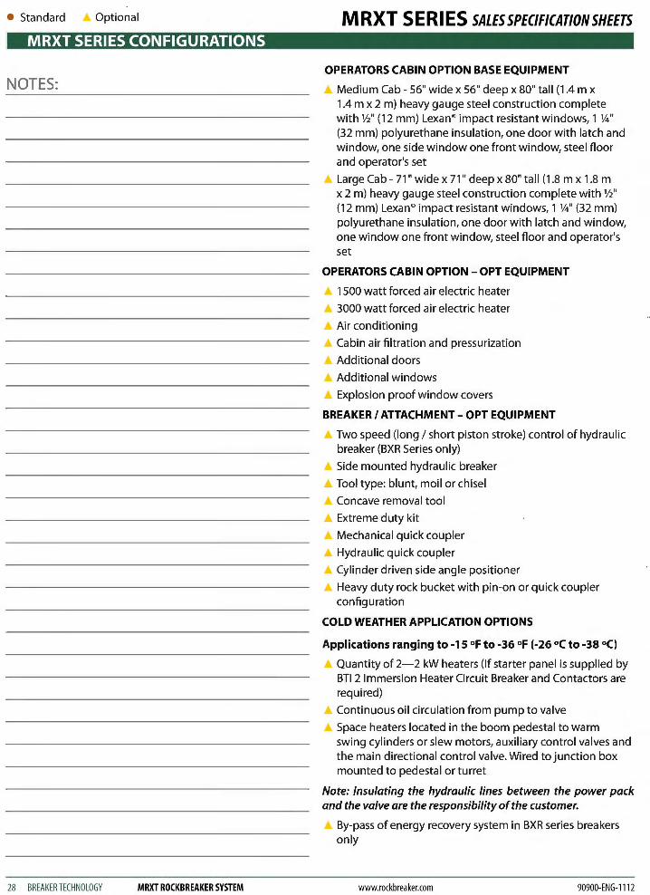
OPERATORS CABIN OPTION BASE EQUIPMENT
Medium Cab- 56" wide x 56" deep x 80" tall (1.4 m x 1.4 m x 2 m) heavy gauge steel construction complete with%'' (12 mm) Lexan® impact resistant windows, 1 %''
(32 mm) polyurethane insulation, one door with latch and window, one side window one front window, steel floor and operator's set
A Large Cab- 71" wide x 71" deep x 80" tall (1.8 m x 1.8 m x 2 m) heavy gauge steel construction complete with%'' (12 mm) Lexan® impact resistant windows, 1 %" (32 mm) polyurethane insulation, one door with latch and window, one window one front window, steel floor and operator's set
OPERATORS CABIN OPTION- OPT EQUIPMENT
1500 watt forced air electric heater
3000 watt forced air electric heater
Air conditioning
Cabin air filtration and pressurization
Additional doors
Additional windows
Explosion proof window covers
BREAKER I ATTACHMENT- OPT EQUIPMENT
Two speed (long I short piston stroke) control of hydraulic breaker (BXR Series only)
A Side mounted hydraulic breaker
Tool type: blunt, moil or chisel
Concave removal tool
A Extreme duty kit
A Mechanical quick coupler
Hydraulic quick coupler
.A Cylinder driven side angle positioner
Heavy duty rock bucket with pin-on or quick coupler configuration
COLD WEATHER APPLICATION OPTIONS
Applications ranging to -15 of to -36 of (-26 °C to -38 °C)
Quantity of 2-2 kW heaters (If starter panel is supplied by BTl 2 Immersion Heater Circuit Breaker and Contactors are required)
A Continuous oil circulation from pump to valve
.A Space heaters located in the boom pedestal to warm swing cylinders or slew motors, auxiliary control valves and the main directional control valve. Wired to junction box mounted to pedestal or turret
Note: Insulating the hydraulic lines between the power pack and the valve are the responsibility of the customer.
By-pass of energy recovery system in BXR series breakers only
www.rockbreaker.com 90900-ENG-1112

M RXT S E Rl ES SALES SPECIFICATION SHEETS MRXT SERIES CONFIGURATIONS
NOTES:
90900-ENG-1112 www.rockbreaker.com
• Standard Optional
COLD WEATHER APPLICATION OPTIONS
Main control valve insulated shrouding, insulated pedestal I turret
It is recommended that the power pack be located within a heated enclosure. BTl can supply these power pack enclosures which are listed separately
Applications Ranging to -30 °f to -50 °f (-34 octo -45 oc
A Quantity of 2-2 kW heaters (If starter panel is supplied by BTl 2 Immersion Heater Circuit Breaker and Contactors are required)
A Main control valve insulated shrouding, insulated pedestal I turret
Space heaters located in the boom pedestal to warm swing cylinders or slew motors, auxiliary control valves and the main directional control valve. Wired to junction box mounted to pedestal or turret
Heat trace lines from the power pack to the main control valve and back on the pressure and return lines, load sense control lines etc. that run between the main directional control valve and the power pack. Heat trace control panel clw ambient sensing thermostat included and mounted to pedestal. Consult factory for longer heat trace lines
Note: Insulating of the hydraulic lines between the power pack and the valve are the responsibility of the customer.
Complete oil circulation system between the main control valve boom cylinders and breaker. This requires the use of a Parker IQAN control system, counterbalance and bypass valves mounted to all boom cylinders, rework to the internal porting of the hydraulic breaker to allow circulation of small volumes of oil through the breaker without cycling the piston
By-pass of energy recovery system in BXR series breakers only
It is recommended that the power pack be located within a heated enclosure. BTl can supply these power pack enclosures which are listed separately.
A Optional Circulation Pump- 3 HP Hydraulic Oil Circulation Pump to run cold weather package without main pump drive motor.
Optional Power Pack Enclosure Cabin clw Louvered vents, qty. 2 access doors, steel construction, R20 insulation, location for motor starter panel, location for grease pumps, interior lighting, 3000 watt heater on thermostat control to heat enclosure area
LOW TEMPERATURE PLATE STEEL OPTION
Upgrade WT grade Category four, charpy tested to 20 lb·f at -so °F ( 89 N at -46 °C)
MRXT ROCKBREAKER SYSTEM BREAKERTECHNOLOGY 29
• Standard Optional
MRXT POWER PACK FEATURES
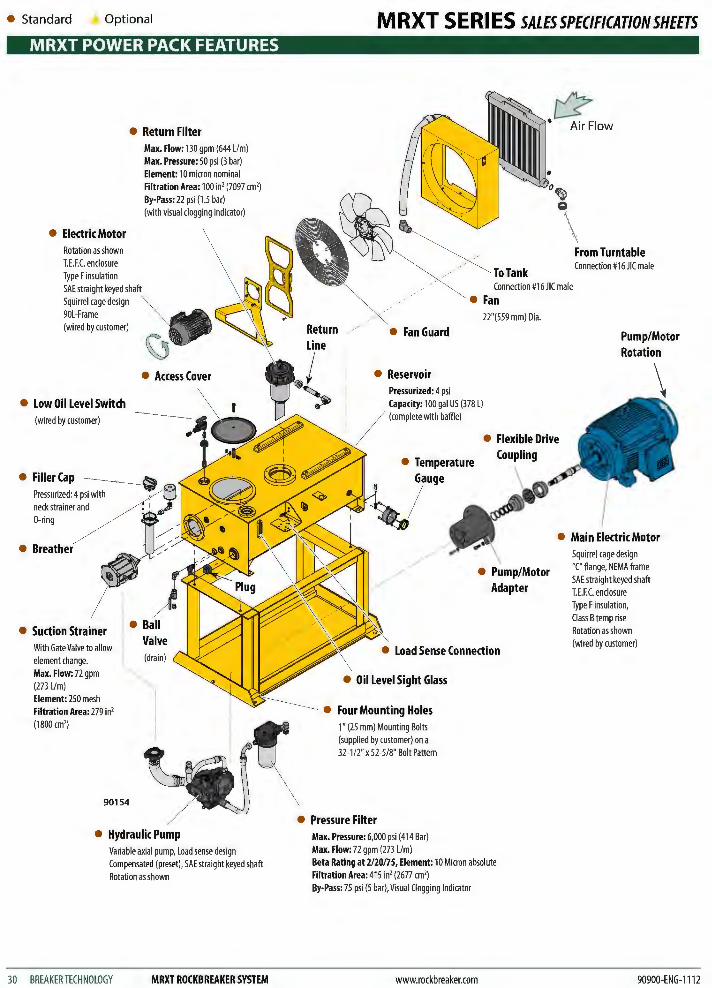
• Return Filter
• Electric Motor Rotation as shown T.E.F.C. enclosure Type F insulation SAE straight keyed shaft Squirrel cage design 90L-Frame (wired by customer)
• Low Oil Level Switch (wired by customer)
Max. Flow: 130 gpm (644 Lim) Max. Pressure: 50 psi (3 bar) Element: 10 micron nominal Filtration Area: 100 in' (7097 em') By·Pass: 22 psi (1.5 bar) (with visual clogging indicator)
• FillerCap ----------~ Pressurized: 4 psi with . neck strainer and 0-ring
• Breather
• Suction Strainer With Gate Valve to allow element change. Max. Flow: 72 gpm (273 Li m) Element: 250 mesh Filtration Area: 279 in' (1800 em')
90154
• Hydraulic Pump Variable axial pump, Load sense design Compensated (preset), SAE straight keyed shaft Rotation as shown
30 BREAKER TECHNOLOGY MRXT ROCKBREAKER SYSTEM
MRXT SERIES SALESSPECIFICATIONSHEETS
.c:? Air Flow
From Turntable Connection #16 JIC male
Connection #16 JIC male
• Fan
• FanGuard
• Reservoir Pressurized: 4 psi Capacity: 100 gal US (378 L) (complete with baffle)
• Temperature Gauge
22"(559 mm) Dia.
• Flexible Drive Coupling
• Pump/Motor Adapter
• Load Sense Connection
• Oil Level Sight Glass
• Four Mounting Holes 1" (25 mm) Mounting Bolts (supplied by customer) on a 32-1i2'' x 52-5i8" Bolt Pattern
• Pressure Filter Max. Pressure: 6,000 psi (414 Bar) Max. Flow: 72 gpm (273 Lim) Beta Rating at 2120ns, Element: 10 Micron absolute Filtration Area: 415 in' (2677 em') By-Pass: 75 psi (5 bar), Visual Clogging Indicator
www.rockbreaker.com
Pump/Motor Rotation
Squirrel cage design "C" flange, NEMA frame SAE straight keyed shaft T.E.F.C. enclosure Type F insulation, Class B temp rise Rotation as shown (wired by customer)
90900-ENG-1112
M RXT S E Rl ES SALES SPECIFICATION SHEETS MRXT POWER PACK FEATURES
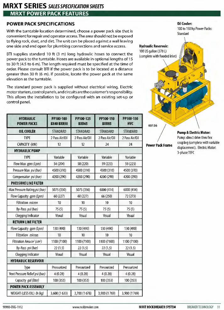
POWER PACK SPECIFICATIONS
With the turntable location determined, choose a power pack site that is convenient for repair and operator access. The area should not be exposed to flying rock, dust, and dirt. The unit can be placed against a wall leaving one side and end open for plumbing connections and service access.
BTl supplies standard 10 ft (3 m) long hydraulic hoses to connect the power pack to the turntable. Hoses are available in optional lengths of 15 to 30ft (4.5 to 6 m). The length required must be specified at the time of order. Please consult BTl if the power pack is to be located at a distance greater than 30 ft (6 m). If possible, locate the power pack at the same elevation as the turntable.
The standard power pack is supplied without electrical wiring. Electric motor starters, control panels, and circuits are the customer's responsibility. This allows the installation to be configured with an existing set-up or control panel.
HYDRAULIC PP100-100 PP100-125 PP100-150 PP100-150 POWER PACKS BX40BXR50 BXR65 BXR85 HVC
OIL COOLER STANDARD STANDARD STANDARD STANDARD
TYPE 2 Pass Air/Oil 2 Pass Air/Oil 2 Pass Air/Oil 2 Pass Air/Oil
CAPACITY (kW) 12 12 24 24
HYDRAULIC PUMP
TYPE Variable Variable Variable Variable
Flow Max gpm (Lpm) 54 (204) 58 (220) 59 (223) 59(223)
Pressure Max psi (bar) 4500 (310) 4500 (310) 4500 (310) 4500 (310)
Compensator psi (bar) 4200 (290) 4200 (290) 4200 (290) 4200 (290)
PRESSURE LINE FILTER
Max Pressure Rating psi (bar) 5075 (350) 5075 (350) 6000 (414) 6000 (414)
Flow Capacity gpm (Lpm) 60 (227) 60 (227) 66 (250) 72 (273)
Filtration micron 10 10 10 10
By-Pass psi (bar) 75 (5) 75 (5) 75 (5) 75 (5)
Clogging Indicator Visual Visual Visual Visual
RETURN LINE FILTER
Flow Capacity gpm (Lpm) 130 (490) 130 (490) 130 (490) 130 (490)
Filtration micron 10 10 10 10
Filtration Area in2 (cm2) 1100 (7100) 1100 (7100) 1100 (7100) 1100 (7100)
By-Pass psi (bar) 22 (1.5) 22 (1.5) 22 (1.5) 22 (1.5)
Clogging Indicator Visual Visual Visual Visual
HYDRAULIC RESERVOIR
Type Pressurized Pressurized Pressurized Pressurized
Vent Pressure Relief psi (bar) 4(0.28) 4(0.28) 4(0.28) 4(0.28)
Capacity gal (liter) 100 (353) 100 (353) 100 (353) 100 (353)
POWER PACK ASSEMBLY
WEIGHT (LESS OIL) lb (kg) 3,600 (1 633) 3,700 (1 678) 3,900 (1 769) 3,900 (1 769)
90900-ENG-1112 www.rockbreaker.com
Hydraulic Reservoir: 100 US gallon (378 L) (complete with flooded inlet)
Power Pack Frame
MRXT ROCKBREAKER SYSTEM
Oil Cooler: 100 to 150 hp Power Packs: Standard
Pump & Electric Motor: Pump: direct drive thru flex coupling (complete with variable displacement). Electric Motor: 3-phase TEFC
BREAKERTECHNOLOGY 31
• Standard Optional
MRXT POWER PACK FEATURES
POWER PACK SPECIFICATIONS
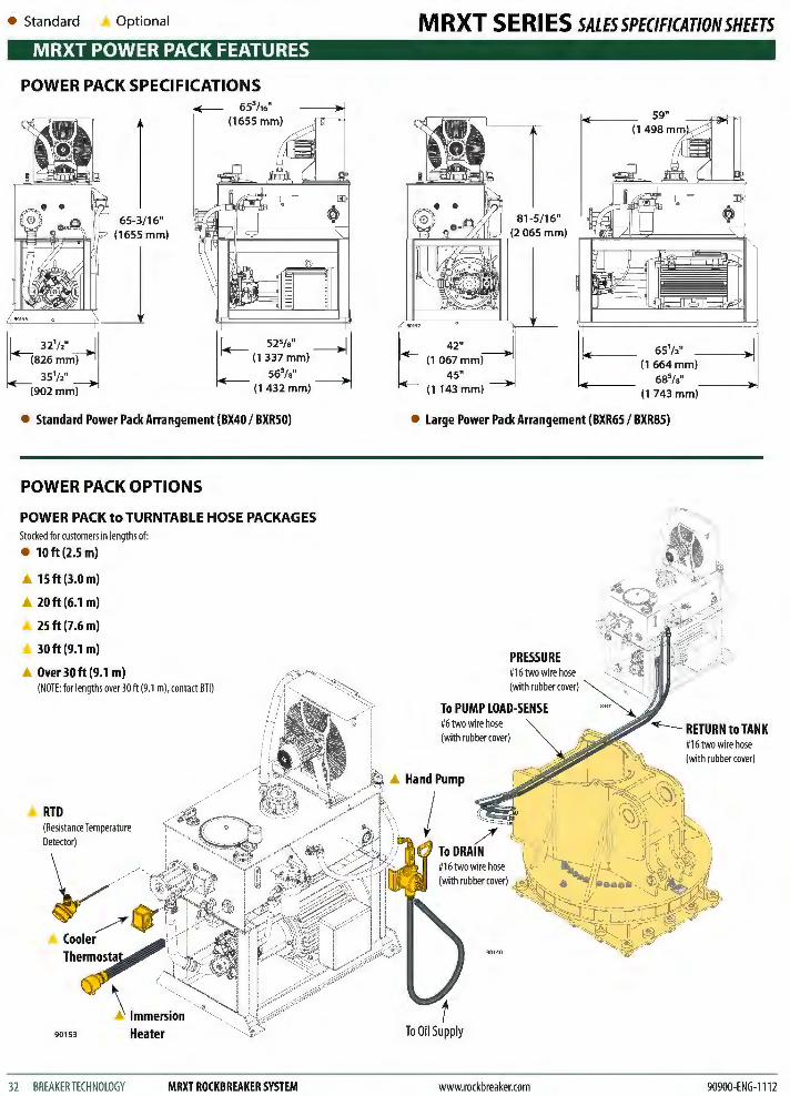
t 32
1/"d ~826~m~ 351/2''
(902 mm}
65-3/16" (1655 mm}
~ 653/16' (1655 mm}
t 525/" j
(1 337 ~m} 563/s"
(1432 mm}
• Standard Power Pack Arrangement (BX40 I BXR50)
POWER PACK OPTIONS
POWER PACK to TURNTABLE HOSE PACKAGES Stocked for customers in lengths of:
• 10ft (2.5 m)
• 15ft (3.0 m)
• 20ft(6.1 m)
25ft(7.6m)
30ft(9.1 m)
• Over 30ft (9.1 m) (NOTE: for lengths over 30ft (9.1 m), contact BTl )
RTD (Resistance Temperature Detector)
90153
32 BREAKER TECHNOLOGY MRXT ROCKBREAKER SYSTEM
MRXT SERIES SALESSPECIFICATIONSHEETS
81-5/16"
re==~~ll (2 065 mm}
Cl 65112" =[
(1664mm}
685/s" (1 743 mm}
• Large Power Pack Arrangement (BXR65 I BXR85)
A Hand Pump
j
To Oil Supply
www.rockbreaker.com
#16 two wire hose (with rubber cover)
90900-ENG-1112
M RXT S E Rl ES SALES SPECIFICATION SHEETS • Standard Optional
MRXT CONTROL FEATURES
90150
~Control Valve
Turntable Assembly
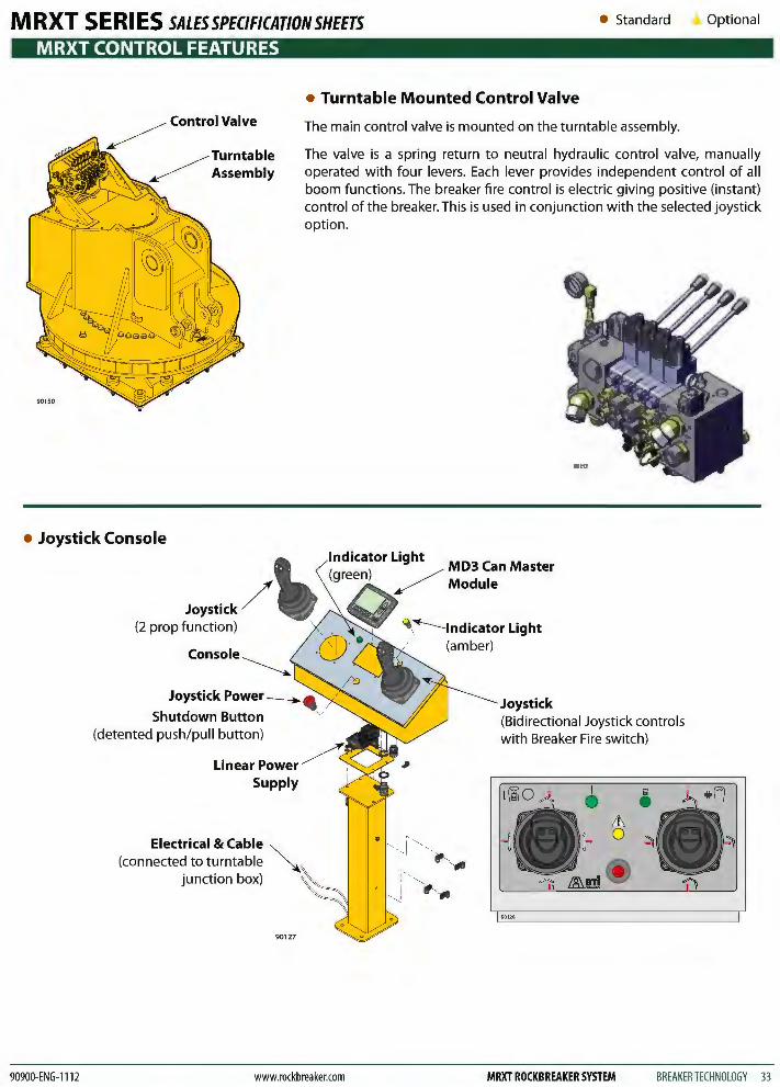
• Turntable Mounted Control Valve
The main control valve is mounted on the turntable assembly.
The valve is a spring return to neutral hydraulic control valve, manually operated with four levers. Each lever provides independent control of all boom functions. The breaker fire control is electric giving positive (instant) control of the breaker. This is used in conjunction with the selected joystick option.
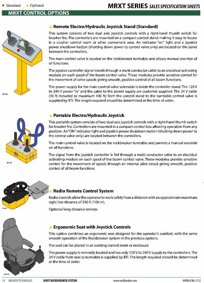
• Joystick Console
90900-ENG-1112
Joystick/ (2 prop function)
Joystick Power-----.. 4& Shutdown Button "
(detented push/pull button)
Linear Power Supply
Electrical & Cable (connected to turntable
junction box)
901 27
ndicator Light MD C M ( ) / 3 an aster green / Module
q.~lndicator Light ,- (amber)
Joystick (Bidirectional Joystick controls with Breaker Fire switch)
www.rockbreaker.com MRXT ROCKBREAKER SYSTEM BREAKER TECHNOLOGY 33
• Standard Optional MRXT SERIES SALESSPECIFICATIONSHEETS MRXT CONTROL OPTIONS
90126
34 BREAKER TECHNOLOGY
Remote Electro/Hydraulic Joystick Stand (Standard)
This system consists of two dual axis joystick controls with a right-hand thumb switch for breaker fire. The controllers are mounted on a compact control stand making it easy to locate in a crusher control room or other convenient area. An indicator "on" light and a joystick power shutdown button (shutting down power to control valve only) are located on the stand between the controllers.
The main control valve is located on the rockbreaker turntable and allows manual override of all functions.
The joystick controller signal travels through a multi conductor cable to an electrical activating module on each spool of the boom control valve. These modules provide sensitive control for the movement of valve spools giving smooth, positive control of all boom functions.
The power supply for the main control valve solenoids is inside the controller stand. The 120 V to 240 V power "in" and the cable to the power supply are customer supplied. The 24 V cable (30 ft included to maximum 100 ft) from the control stand to the turntable control valve is supplied by BTl. The length required should be determined at the time of order.
• Portable Electro/Hydraulic Joystick
This portable system consists of two dual axis joystick controls with a right-hand thumb switch for breaker fire. Controllers are mounted in a compact control box allowing operation from any position. An "ON" indicator light and joystick power shutdown button (shutting down power to the central valve only) are located between the controllers.
The main control valve is located on the rockbreaker turntable and permits a manual override on all functions.
The signal from the joystick controller is fed through a multi conductor cable to an electrical activating module on each spool of the boom control valve. These modules provide sensitive control for the movement of spools through an internal pilot circuit giving smooth, positive control of all boom functions
Radio Remote Control System
Radio controls allow the operator to work safely from a distance with an approximate maximum sight line distance of 330ft (100m).
Optional long distance remote.
Ergonomic Seat with Joystick Controls
This option combines an ergonomic seat designed for the operator's comfort, with the same smooth operation of the Rockbreaker system in the previous options.
The seat can be placed in an existing control room or enclosure
The power supply is remotely located and has only 120 V to 240 V supply to the controllers. The 24 V cable from seat to turntable is supplied by BTl. The length required should be determined at the time of order.
MRXT ROCKBREAKER SYSTEM www.rockbreaker.com 90900-ENG-1112
MRXT SERIES SALES SPECIFICATION SHEETS MRXT IQAN™ SYSTEM
• IQAN™ CAN BUS SYSTEM
IQANTM is a state-of-the-art system, developed to electrically control and monitor hydraulics in a stationary boom system.
IQANTM communicates with and displays data from systems on the rockbreaker, such as the lubrication system, control valve, and etc.IQAN'M also allows control of these systems.
IQANTM is user-programmable via a high-level graphical design tool, dramatically simplifying development. Simulation ofthe control system takes place in parallel with the programming of machine functions.
Servicing is greatly simplified in a number of ways. Sensors can easily be calibrated in the field and any error is recorded
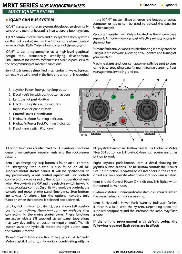
1. Joystick Power Emergency Stop button
2. Decal - Left Joystick push-button actions
3. Left Joystick push-button
4. Decal - RH joystick button actions.
5. Right Joystick push-button
6. Control Power ON indicator.
7. Hydraulic Motor Running indicator.
8. Hydraulic Power Pack Warning indicator.
9. Dead man's switch (Optional)
All boom functions are identified by ISO symbols. Functions depend on customer requirements and the rockbreaker system.
Item 1, an Emergency Stop button is found on all controls. An Emergency Stop button is also found on all BTl supplied motor starter panels. It will be operational on any permanently wired control equipment. For controls connected by wire or radio, the button is operational only when the controls are ON and the selector switch turned to the appropriate control. On units with multiple controls, the console and motor starter panel Emergency Stop buttons are always functional, but the optional controls only function when that control is selected and activated.
Left Joystick push-button, item 2, decal shows Left Joystick push-button actions. These functions are available after connecting to the motor starter panel. These functions are active with a BTl supplied starter panel (operations may vary depending on customer requirements). The left button starts the hydraulic motor; the right button stops the hydraulic motor.
lf"dead-man" buttons are active on the joystick, the Hydraulic Motor Start (LH button), only works in combination with the
90900-ENG-1112 www.rockbreaker.com
• Standard Optional
in the IQANTM master. Since all errors are logged, a laptop computer or tablet can be used to upload the data for further analysis.
Very often on-site machinery is located far from home base support. A modem enables cost effective remote access to the machine.
Remote fault analysis and troubleshooting is easily handled using IQAN'M software, allowing easy updates and tuning of your machine.
Machine status and logs can automatically be sent to your home base, providing data for maintenance planning, fleet management, invoicing, and etc.
RH joystick "dead-man" button item 9. The Hydraulic Motor Stop (RH button on LH joystick) does not require any other button to work.
Right Joystick push-button, item 4 decal showing RH joystick button actions. The RH button controls the Breaker Fire. This function is controlled via interlocks in the control circuit and only operate when these interlocks are satisfied.
Item 6 is the Control Power ON indicator. This lights when the control power is on.
Hydraulic Motor Running indicator, item 7, illuminates when the main hydraulic motor is running.
Item 8, Hydraulic Power Pack Warning indicator flashes if there is a fault with the system. Depending upon the supplied equipment and the interface, the lamp may flash a code.
If the unit is programmed with default codes, the following repeated flash codes are in effect:
MRXT ROCKBREAKER SYSTEM BREAKER TECHNOLOGY 35
• Standard Optional
MRXT IQAN™ SYSTEM
1-Fiash. Main motor overload.
2-Fiashes. Cooler motor overload.
3-Fiashes. Low oil level.
4-Fiashes. Main system temperature.
5-Fiashes. Main system pressure.
Alarms 1 to 5 turn off the hydraulic motor.
Low lubrication level (alarm #6) flashes the alarm, and causes the boom functions to slow down and eventually stop (usually within 20 minutes). To operate the boom, the lubricant must be refilled before the next lubrication cycle. Alarm 7 & 9 are optional, and programmed according to customer requirements.
Item 9, is the Dead-man's switch. When activated the operator must push the Dead-man's button to activate a boom function button. These buttons are only activated at customers request.
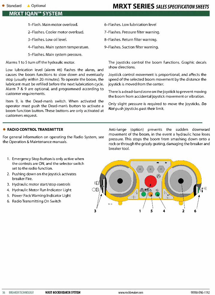
e RADIO CONTROL TRANSMITTER
For general information on operating the Radio System, see the Operation & Maintenance manuals.
1. Emergency Stop button is only active when the controls are ON, and the selector switch set to the radio function.
2. Pushing down on the joystick activates breaker Fire.
3. Hydraulic motor start/stop controls
4. Hydraulic Motor Run Indicator Light
5. Power Pack Warning Indicator Light
6. Radio Transmitting On Switch
36 BREAKER TECHNOLOGY MRXT ROCKBREAKER SYSTEM
3
MRXT SERIES SALESSPECIFICATIONSHEETS
6-Fiashes. Low lubrication level
?-Flashes. Pressure filter warning.
8-Fiashes. Return filter warning.
9-Fiashes. Suction filter warning.
The joysticks control the boom functions. Graphic decals show directions.
Joystick control movement is proportional, and affects the speed of the selected boom movement by the distance the joystick is moved from the center.
There is a dead-band zone on the joystick to prevent moving the boom from accidental joystick movement or vibration.
Only slight pressure is required to move the joysticks. Do Not push joysticks past their limit.
Anti-lunge (option) prevents the sudden downward movement of the boom, in the event a hydraulic hose loses pressure. This stops the boom from smashing down onto a rock or through the grizzly grating, damaging the breaker and breaker tool.
1 5 4 2 6
www.rockbreaker.com 90900-ENG-1112
M RXT S E Rl ES SALES SPECIFICATION SHEETS MRXT- HVC OPTION
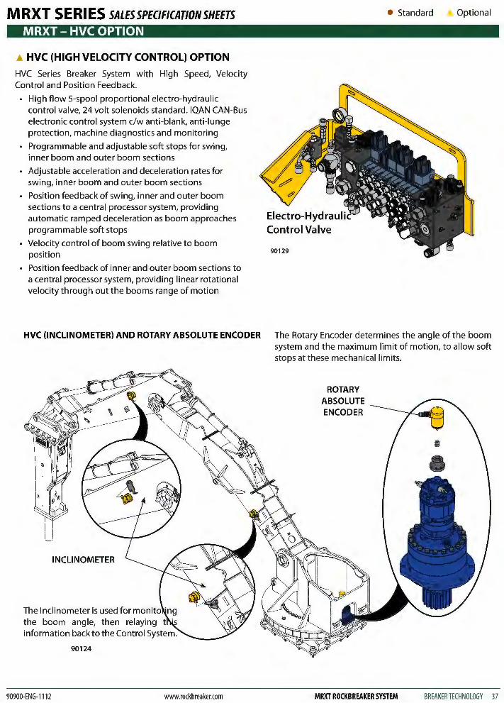
HVC (HIGH VELOCITY CONTROL) OPTION
HVC Series Breaker System with High Speed, Velocity Control and Position Feedback.
High flow 5-spool proportional electro-hydraulic control valve, 24 volt solenoids standard. IQAN CAN-Bus electronic control system c/w anti-blank, anti-lunge protection, machine diagnostics and monitoring
Programmable and adjustable soft stops for swing, inner boom and outer boom sections
Adjustable acceleration and deceleration rates for swing, inner boom and outer boom sections
Position feedback of swing, inner and outer boom sections to a central processor system, providing automatic ramped deceleration as boom approaches programmable soft stops
• Velocity control of boom swing relative to boom position
• Position feedback of inner and outer boom sections to a central processor system, providing linear rotational velocity through out the booms range of motion
• Standard Optional
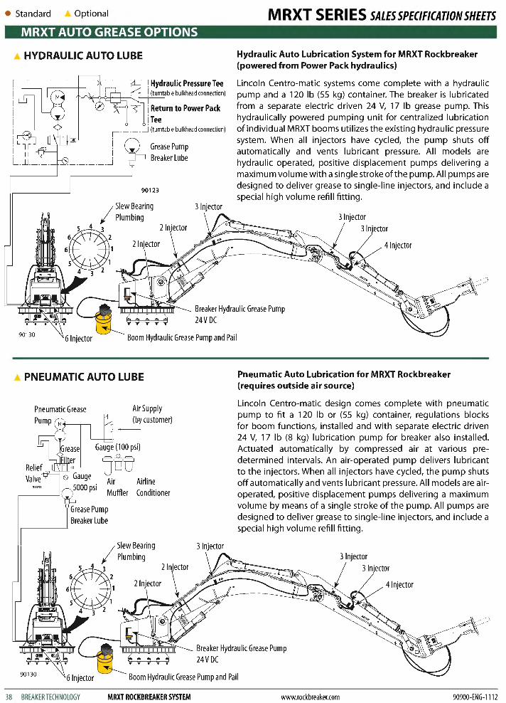
HVC (INCLINOMETER) AND ROTARY ABSOLUTE ENCODER The Rotary Encoder determines the angle of the boom system and the maximum limit of motion, to allow soft stops at these mechanical limits.
INCLINOMETER
The Inclinometer is used for man the boom angle, then relaying information back to the Control System.
90124
90900-ENG-1112 www.rockbreaker.com
ROTARY ABSOLUTE ENCODER
MRXT ROCKBREAKER SYSTEM BREAKER TECHNOLOGY 37
• Standard Optional MRXT SERIES SALESSPECIFICATIONSHEETS MRXT AUTO GREASE OPTIONS
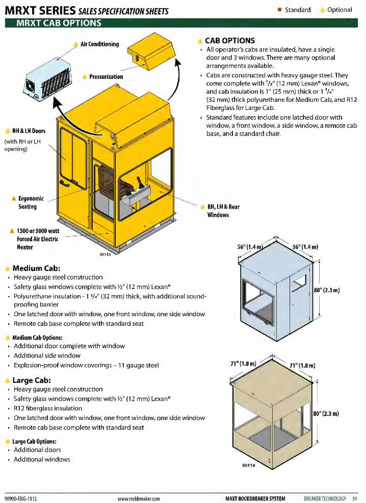
A HYDRAULIC AUTO LUBE Hydraulic Auto Lubrication System for MRXT Rockbreaker (powered from Power Pack hydraulics)
1 _____ _j (turntable bulkhead connection)
Lincoln Centro-matic systems come complete with a hydraulic pump and a 120 lb (55 kg) container. The breaker is lubricated from a separate electric driven 24 V, 17 lb grease pump. This hydraulically powered pumping unit for centralized lubrication of individual MRXT booms utilizes the existing hydraulic pressure system. When all injectors have cycled, the pump shuts off automatically and vents lubricant pressure. All models are hydraulic operated, positive displacement pumps delivering a maximum volume with a single stroke ofthe pump. All pumps are designed to deliver grease to single-line injectors, and include a special high volume refill fitting .
i II j
L_~ ________________ j Grease Pump Breaker Lube
90123
3 Injector
Breaker Hydraulic Grease Pump 24V DC
41njector
90130 Boom Hydraulic Grease Pump and Pail
PNEUMATIC AUTO LUBE
Air Supply (by customer)
Airline Conditioner
3 Injector
Pneumatic Auto Lubrication for MRXT Rockbreaker (requires outside air source)
Lincoln Centro-matic design comes complete with pneumatic pump to fit a 120 lb or (55 kg) container, regulations blocks for boom functions, installed and with separate electric driven 24 V, 17 lb (8 kg) lubrication pump for breaker also installed. Actuated automatically by compressed air at various predetermined intervals. An air-operated pump delivers lubricant to the injectors. When all injectors have cycled, the pump shuts off automatically and vents lubricant pressure. All models are airoperated, positive displacement pumps delivering a maximum volume by means of a single stroke of the pump. All pumps are designed to deliver grease to single-line injectors, and include a special high volume refill fitting.
41njector
Breaker Hydraulic Grease Pump 24V DC
901 30 Boom Hydraulic Grease Pump and Pail
38 BREAKER TECHNOLOGY MRXT ROCKBREAKER SYSTEM www.rockbreaker.com 90900-ENG-1112
M RXT S E Rl ES SALES SPECIFICATION SHEETS MRXT CAB OPTIONS
RH &LH Doors
(with RH or LH opening)
Ergonomic Seating
A 1500 or 3000 watt Forced Air Electric Heater
Medium Cab:
Air Conditioning
-~~~~
• Heavy gauge steel construction
• Safety glass windows complete with V2" (12 mm) Lexan®
• Standard Optional
CAB OPTIONS • All operator's cabs are insulated, have a single
door and 3 windows. There are many optional arrangements available.
• Cabs are constructed with heavy gauge steel. They come complete with 1/2" (12 mm) Lexan® windows, and cab insulation is 1" (25 mm) thick or 1 114'' (32 mm) thick polyurethane for Medium Cab, and R12 Fiberglass for Large Cab.
• Standard features include one latched door with window, a front window, a side window, a remote cab base, and a standard chair.
RH, LH& Rear Windows
80" (2.3 m} • Polyurethane insulation- 1 114'' (32 mm) thick, with additional sound
proofing barrier J • One latched door with window, one front window, one side window
• Remote cab base complete with standard seat
Medium Cab Options: • Additional door complete with window
• Additional side window
• Explosion-proof window coverings- 11 gauge steel
Large Cab: • Heavy gauge steel construction
• Safety glass windows complete with V2" (12 mm) Lexan®
• R12 fiberglass insulation
• One latched door with window, one front window, one side window
Remote cab base complete with standard seat
.A Large Cab Options: • Additional doors
• Additional windows
90900-ENG-1112 www.rockbreaker.com MRXT ROCKBREAKER SYSTEM BREAKER TECHNOLOGY 39

• Standard Optional
MRXT OTHER OPTIONS
A COLD WEATHER INSTALLATION PACKAGES
For Applications Ranging from: -15 °F to -30 °F (-26 °( to -34 °(} c/w
• Qty. 2- 2 kW heaters (If starter panel is supplied by BTl then two Immersion Heater Circuit Breaker and Contactors are required).
• Continuous oil circulation from pump to valve
• Main control valve insulated shrouding
• Space heaters located in the boom turntable to warm slew motors, auxiliary control valves and the main directional control valve. Wired to junction box mounted to turntable.
• Heat trace lines from the power pack to the main control valve and back on the main suction, pressure and return lines, load sense control lines and etc. that run between the main directional control valve and the power pack. Heat trace control panel c/w ambient sensing thermostat included and mounted to turntable.
• Cold temperature steel.
It is recommended that the power pack be located within a heated enclosure. BTl can supply these power pack enclosures.
Note: Insulating of the hydraulic lines between the power pack and the valve are the responsibility of the customer.
Note: By-pass of energy recovery system in BXR series breakers only.
COMMISSIONING* • Services of a BTl service representative are required for
installation supervision or start-up and commissioning (flow and pressure checks, operation and maintenance training).
1. The customer is responsible to make arrangements to have 2 laborers, 1 welder, and a suitable crane with operator, to work with the BTl service representatives.
2. The customer is responsible for the electrical installation.
40 BREAKER TECHNOLOGY MRXT ROCKBREAKER SYSTEM
MRXT SERIES SALESSPECIFICATIONSHEETS
For Applications Ranging from: -25 °F to -45 °F (-32 °( to -43 °(} c/w
• Qty. 2- 2 kW heaters (If starter panel is supplied by BTl then two Immersion Heater Circuit Breaker and Contactors are required).
• Optional 3 hp Circulation Pump available, for continuous oil supply to boom system without need for the main power pack pump.
• Main control valve insulated shrouding
• Space heaters located in the boom turntable to warm slew motors, auxiliary control valves and the main directional control valve. Wired to junction box mounted to turntable.
• Heat trace lines from the power pack to the main control valve and back on the pressure and return lines, load sense control lines etc. that run between the main directional control valve and the power pack. Heat trace control panel c/w ambient sensing thermostat included and mounted to turntable.
• Complete oil circulation system between the main control valve boom cylinders and breaker. It is recommended that the power pack be located within a heated enclosure. BTl can supply these power pack enclosures which are listed separately.
Note: Insulating of the hydraulic lines between the power pack and the valve are the responsibility of the customer.
Note: By-pass of energy recovery system in BXR series breakers only.
3. The customer is responsible for proper site preparation, and installation hardware per the BTl installation manual.
* Regular time hourly rate. Overtime rate applies after 8 hours/day and weekends. Expenses are additional.
www.rockbreaker.com 90900-ENG-1112

M RXT S E Rl ES SALES SPECIFICATION SHEETS • Standard Optional
MRXT BREAKER OPTIONS
~Tool ~Hex Nut
~Adapter Weldment
CONCAVEREMOVALTOOL Tool Assembly consists of:
1 -Long Tool, 72" (1 829 mm)
1 -Adapter Welded Assembly used for mounting the Tooth to the tool 1 -Bolt, 3/4" X 7" (178 mm) long 1 - Hex Nut, 3/4" 1 -Washer, 3/4" dia (to lock assembly in place)
Note: Customer is responsible for supplying the Tooth and welding the Tooth to the Adapter Welded Assembly.
• The Adapter Welded Assembly can be purchased separately, however the tool is only sold with an Adapter.
• The Concave Removal Tool is used in Gyratory Crushers to remove the steel liners from inside the crushing chamber.
• Mounting the tool to the breaker replaces the need for laborers to enter the chamber and manually scrape and pry damaged steel tiles from the sides.
• Using the BTl Concave Removal Tool provides a much safer and more economical way to accomplish this task.
(customer supplied)
Steel Tiles
Standard Gyratory Crusher showing the steel tiles lining the inside of the crushing chamber.
90115
90900-ENG-1112 www.rockbreaker.com MRXT ROCKBREAKER SYSTEM BREAKER TECHNOLOGY 41
• Standard Optional
MRXT BREAKER OPTIONS
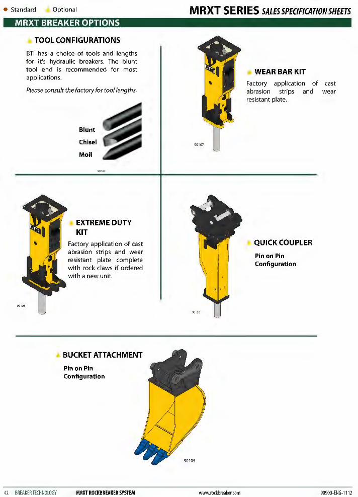
TOOL CONFIGURATIONS
BTl has a choice of tools and lengths for it's hydraulic breakers. The blunt tool end is recommended for most applications.
Please consult the factory for too/lengths.
42 BREAKER TECHNOLOGY
Blunt
Chisel
Moil
EXTREME DUTY KIT
Factory application of cast abrasion strips and wear resistant plate complete with rock claws if ordered with a new unit.
BUCKET ATTACHMENT
Pin on Pin Configuration
MRXT ROCKBREAKER SYSTEM
MRXT SERIES SALESSPECIFICATIONSHEETS
90105
www.rockbreaker.com
WEAR BAR KIT
Factory application of cast abrasion strips and wear resistant plate.
QUICK COUPLER
Pin on Pin Configuration
90900-ENG-1112

MRXT SERIES SALESSPEC/FICAT/ONSHEETS
90900-ENG-0712 www.rockbreaker.com MRXT ROCKBREAKER SYSTEM BREAKER TECHNOLOGY 43

All dimensions and specifications are subject to change without notice.
II 1!1 .. ,·