Embed Size (px)
Citation preview

Indu
stria
l Sho
ck A
bsor
bers Automation Control Equipment
USA ACE CONTROLS INC.
23435 Industrial Park Dr., Farmington HillsMI 48335, USA Tel.: +1-248-476-0213Fax: +1-248-476-2470www.acecontrols.com
GERMANY ACE STOSSDÄMPFER GMBH
Albert-Einstein-Straße 1540764 Langenfeld, GermanyTel.: +49-(0) 2173-9226-10Fax: +49-(0) 2173-9226-19www.ace-ace.de
GREAT BRITAIN ACE CONTROLS INTERNATIONAL
Unit 404 Easter Park, Haydock LaneHaydock, WA11 9TH, U.K.Tel.: +44-(0) 1942 727440Fax: +44-(0) 1942 717273www.ace-controls.co.uk
JAPAN ACE CONTROLS JAPAN L.L.C.
City Center Bldg. II 2fl 3-1-42, Chigasaki-minami, Tsuzuki-ku Yokohama, 224-0037, JapanTel.: +81-(45) 945-0123Fax: +81-(45) 945-0122 www.acecontrols.co.jp
P.R. CHINA ACE CONTROLS (SUZHOU) CO. LTD.
Building 7 East, No. 369 Lushan Road, SuzhouJiangsu Province 215129, P. R. ChinaTel.: +86-(512) 88606699Fax: +86-(512) 88606698www.acecontrols.cn.com
Distributors in other countries see pages 170 and 171.
Editi
on 7
/201
4
Sales Locations
ACE Controls Inc. 23435 Industrial Park Dr., Farmington Hills, MI 48335Tel. +1- 248 - 476-0213 · Fax +1- 248 - 476-2470 · [email protected] · www.acecontrols.com
IndustrialShock Absorbers
SafetyShock Absorbers
TUBUSProfile Dampers
Dampers/Feed Controls
IndustrialGas Springs
Main CatalogEdition 7/2014
New Models
New Models
New Models

Issu
e 7.
2014
Spe
cific
atio
ns s
ubje
ct to
cha
nge
2 171
Distributor Stock LocationsNorth and Central America
ACE Controls Inc. · Tel. 800-521-3320 · (248) 476-0213 · Fax (248) 476-2470 · E-mail: [email protected] · www.acecontrols.com ACE Controls Inc. · Tel. 800-521-3320 · (248) 476-0213 · Fax (248) 476-2470 · E-mail: [email protected] · www.acecontrols.com
Canada
Central America
Location City Distributor Telephone Internet
British Columbia Burnaby Peerless Engineering Sales Ltd. (604) 659-4100 (604) 659-4121 www.peerlesse.com
Ontario Stoney Creek Vickers-Warnick Limited (905) 643-1448 (905) 643-9785 www.vickers-warnick.com
Quebec Lachine Cowper Incorporated (514) 637-6746 (514) 637-5055 www.copwer.ca
Location City Distributor Telephone Internet
Costa Rica San José Grupo Kopar (81) 8000-2000 (81) 8000-2001 www.kopar.com.mx
Mexico Monterrey Grupo Kopar (81) 8000-2000 (81) 8000-2001 www.kopar.com.mx
Puerto Rico Caguas P & C Company (787) 768-5033 (787) 744-8306 N/A San Juan Rafael Benitez Carrillo, (787) 725-7635 (787) 723-1257 http://web.applied.com/ Inc./Applied Ind. base.cfm?page_id=2754
Issu
e 7.
2014
Spe
cific
atio
ns s
ubje
ct to
cha
nge
Locate and EliminateDisturbing Vibration
Free App for iPhone, iPad and iPod Touch 3-Axis measurement system Simple & comprehensible menu Immediate product recommendation Available in English, German and French
Vibration Isolation
Keep it calm.Measure your possibilities.
www.vibrochecker.com
easy & free

ACE Controls Inc. · Tel. 800-521-3320 · (248) 476-0213 · Fax (248) 476-2470 · E-mail: [email protected] · www.acecontrols.com 3
Issu
e 7.
2014
Spe
cific
atio
ns s
ubje
ct to
cha
nge
All rights to the production, trade names, design and illustrations of this catalog are reserved. No part of this publication may be reproduced, copied or printed without permission; violations will be prosecuted. Construction, dimensions and specifications of ACE products are subject to change.
Technical SupportFree Additional Services
Certified Quality
ACE products are exclusively manufactured from high quality and environmentally compatible materials. With permanent quality monitoring and the performance of test programs, a constant high quality can be guaranteed. ACE pursues continual improvement in all areas in order to arrange material and energy consumption, the production of damaging substances and recycling or disposal of end products as gently on resources as possible. It is important to us to keep the strain on the environment as low as possible and simultaneously improve our services. With ongoing optimization of end products, we also give our customers the option of designing their products to be smaller, more effective and more energy-saving.
On this page we would like to present our free additional services. We provide these services to assist you from identifi-cation of the problem to the solution. Tell us about your requirements. Take advantage of our more than 40 years of expert knowledge in damping technology. Furthermore: ACE service support and products are available in more than 40 countries worldwide.
Our specialist engineers create detailed technical solutions for you including assembly suggestions and details on machine loads, brake time and workload etc.
With our user-friendly calculation program on the internet you can select the right product – online or via download of the program. The CAD data is available in all standard formats in 2D and 3D.

ACE Controls Inc. · Tel. 800-521-3320 · (248) 476-0213 · Fax (248) 476-2470 · E-mail: [email protected] · www.acecontrols.com4
Index
Industrial Shock Absorbers
Safety Shock Absorbers
TUBUS Bumpers
Industrial shock absorbers are used as hydraulic machine components for slowing down moving loads with minimal reaction force. ACE shock absorbers are characterized by the use of the most recent and innovative technolo-gies such as the piston tube, stretch or rolling diaphragm seals. Thus, the shock absorbers offer the longest service life in high energy absorption.
ACE industrial shock absorbers are machine components that are easy to use and also flexible in use with their multitude of optional accessories.
Safety shock absorbers are used to provide security in emergency stop applications. Auto warehouse units, conveyors, or crane equip-ment, they are an inexpensive alternative to in- dustrial shock absorbers. Safety shock absorbers are maintenance-free, self-contained and con- structed with an integrated positive stop. They feature an integrated diaphragm accumulator or work with a compressed nitrogen bladder. ACE
offers safety shock absorbers with strokes from 23 to 1200 mm. Following model selection we calculate the layout of the damping orifices for your individual requirements.
The innovative TUBUS bumpers are a cost-efficient alternative for emergency stop applications and continous use. They are made from a special co-polyester elastomer. They constantly absorb energies in areas in which other materials fail. The excellent damping characteristics are achieved as a result of the special elastomer material and the world-wide-patented design. The bumpers are constructed
to absorb energy with a damping curve that is declining (TA-series), almost linear (TS-series) or progressive (TR-series). The TUBUS series comprises 7 main types with over 140 individual models.
Hydraulic Dampers and Feed Controls
Feed controls are infinitely adjustable and provide accurate feed rate control. They are ideal for sawing, grinding and boring machines.
Hydraulic dampers are used to control traverse rates. They can control the parallel feed in both directions or be used as a compensating element for moving loads. As a security element, they prevent the sudden retraction of devices.
Industrial Gas Springs Gas springs (push type) can be used with all applications in which the lifting and lowering of loads must be controlled. They support manual forces and are used to control the lifting and lowering of lids, flaps, hoods etc. They are main- tenance-free, self-contained and deliverable from stock. Their integral grease chamber provides a lower breakaway force, reduced friction and extremely long life.
Industrial traction gas springs are effective in the pulling direction. Both types are fitted with a valve. This allows matching to the required force for any application.
ACE Controls Inc. · Tel. 800-521-3320 · (248) 476-0213 · Fax (248) 476-2470 · E-mail: [email protected] · www.acecontrols.com 5
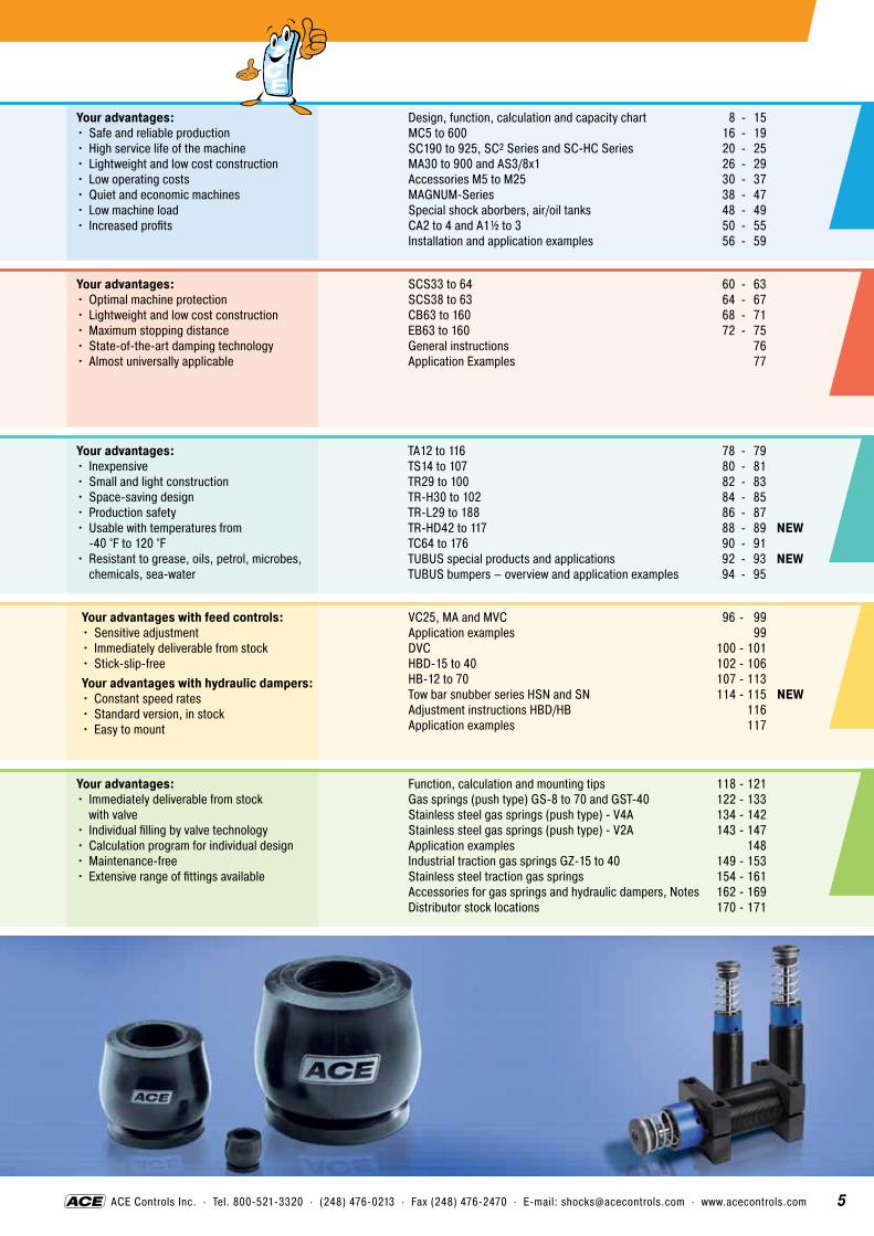
Your advantages:•Safe and reliable production•High service life of the machine •Lightweight and low cost construction•Low operating costs•Quiet and economic machines•Low machine load • Increased profits
Your advantages:•Optimal machine protection •Lightweight and low cost construction•Maximum stopping distance •State-of-the-art damping technology •Almost universally applicable
Your advantages:• Inexpensive •Small and light construction •Space-saving design •Production safety • Usable with temperatures from
-40 °F to 120 °F• Resistant to grease, oils, petrol, microbes,
chemicals, sea-water
Design, function, calculation and capacity chartMC5 to 600SC190 to 925, SC2 Series and SC-HC SeriesMA30 to 900 and AS3/8x1Accessories M5 to M25MAGNUM-SeriesSpecial shock aborbers, air/oil tanksCA2 to 4 and A1½ to 3Installation and application examples
8 - 15 16 - 19 20 - 25 26 - 29 30 - 37 38 - 47 48 - 49 50 - 55 56 - 59
SCS33 to 64SCS38 to 63CB63 to 160EB63 to 160General instructionsApplication Examples
60 - 63 64 - 67 68 - 71 72 - 75 76 77
TA12 to 116TS14 to 107TR29 to 100TR-H30 to 102TR-L29 to 188TR-HD42 to 117TC64 to 176TUBUS special products and applicationsTUBUS bumpers – overview and application examples
78 - 79 80 - 81 82 - 83 84 - 85 86 - 87 88 - 89 NEW 90 - 91 92 - 93 NEW 94 - 95
Your advantages with feed controls:•Sensitive adjustment • Immediately deliverable from stock •Stick-slip-freeYour advantages with hydraulic dampers:•Constant speed rates •Standard version, in stock •Easy to mount
VC25, MA and MVCApplication examplesDVCHBD-15 to 40HB-12 to 70Tow bar snubber series HSN and SNAdjustment instructions HBD/HBApplication examples
96 - 99 99 100 - 101102 - 106 107 - 113 114 - 115 NEW 116 117
Your advantages:• Immediately deliverable from stock
with valve• Individual filling by valve technology •Calculation program for individual design•Maintenance-free •Extensive range of fittings available
Function, calculation and mounting tipsGas springs (push type) GS-8 to 70 and GST-40Stainless steel gas springs (push type) - V4AStainless steel gas springs (push type) - V2AApplication examplesIndustrial traction gas springs GZ-15 to 40Stainless steel traction gas springsAccessories for gas springs and hydraulic dampers, NotesDistributor stock locations
118 - 121 122 - 133 134 - 142 143 - 147 148 149 - 153 154 - 161 162 - 169 170 - 171

ACE Controls Inc. · Tel. 800-521-3320 · (248) 476-0213 · Fax (248) 476-2470 · E-mail: [email protected] · www.acecontrols.com6
Issu
e 7.
2014
Spe
cific
atio
ns s
ubje
ct to
cha
nge
An Unbeatable Range
ACE industrial shock absorbers are high quality dampers for smooth deceleration in end position of automatic processes. High energy absorption capacity and solid construction guarantee a long lifespan; including in harsh environments. The absorbers are available in various sizes to slow down masses weighing just a few ounces to more than 225,000 pounds.
Features• Increase in production •Long lifespan of the machine •Simple, inexpensive construction •Quiet, energy saving machines •Available in diameters from 0.2 in to 7.5 in •Delivery in 24 hours
ACE safety shock absorbers are designed for emergency-stop situations in industrial and crane applications. They are individually tailored to the relevant application for emergency-stop.
Application examples•Portal cranes •Conveyor systems •Automated storage and retrieval systems •Harbour cranes and bridges•Floodgates
ACE Industrial Shock Absorbers
ACE Safety Shock Absorbers
ACE-TUBUS bumpers are the alternative for applications in which the mass does not have to be stopped in an exact position or the energy does not have to be 100% removed.
Features•Low weight •Small installation size • Inexpensive safety element •Simple assembly •Up to 73 % energy absorption •For use in clean rooms
With the kind permission of Worthmann Maschinenbau GmbH
ACE-TUBUS Bumpers
www.acecontrols.com

ACE Controls Inc. · Tel. 800-521-3320 · (248) 476-0213 · Fax (248) 476-2470 · E-mail: [email protected] · www.acecontrols.com 7
Issu
e 7.
2014
Spe
cific
atio
ns s
ubje
ct to
cha
nge
An Unbeatable Range
ACE hydraulic dampers and feed controls help you precisely regulate critical feeds in the wood, plastic, metal and glass industry.
Features•Constant speed •Precise control •Control in both directions•Strokes up to 31.5 inches •Forces up to 11,241 lbs •Adjustable •Delivery in 24 hours
ACE gas springs support muscle power and help you with the controlled lifting and lowering of lids, hoods, flaps and machine screens.
Features•Reduction of the muscle power required •Large forces in small units •Controlled input and output speeds •Controlled movement using just one finger • Increased safety •Adjustable •Delivery in 24 hours
ACE Hydraulic Dampers and Feed Controls
ACE Industrial Gas Springs
www.acecontrols.com

8
8
Issu
e 7.
2014
Spe
cific
atio
ns s
ubje
ct to
cha
nge
ACE Controls Inc. · Tel. 800-521-3320 · (248) 476-0213 · Fax (248) 476-2470 · E-mail: [email protected] · www.acecontrols.com
Virtually all manufacturing processes involve movement of some kind. In production machinery this can involve linear transfers, rotary index motions, fast feeds etc. At some point these motions change direction or come to a stop. Any moving object possesses kinetic energy as a result of its motion and if the object changes direction or is brought to rest, the dissipation of this kinetic energy can result in destructive impact forces within the structural and operating parts of the machine. Kinetic energy increases as the square of the speed and the heavier the object, or the faster it travels, the more energy it has. An increase in production rates is only possible by dissi- pating this kinetic energy smoothly and thereby eliminating destructive deceleration forces. Older methods of energy absorption such as rubber buffers, springs, hydraulic dashpots and cylinder cushions do not provide this required smooth deceleration characteristic – they are non linear and produce high peak forces at some point during their stroke. The optimum solution is achieved by an ACE industrial shock absorber. This utilizes a series of metering orifices spaced throughout its stroke length and provides a constant linear deceleration with the lowest possible reaction force in the shortest stopping time.ACE Controlled Linear Deceleration!
Stopping with Rubber Bumpers, Springs, Dashpots or Cylinder Cushions
Stopping with ACE Shock Absorbers
•Loss of production•Machine damage • Increased maintenance costs • Increased operating noise •Higher machine construction costs
• Increased production• Increased operating life of the machine• Improved machine efficiency • Reduced construction costs of the
machine•Reduced maintenance costs •Reduced noise pollution •Reduced energy costs
Result
Your Advantages
ACE Wine Drop Display PropertyAn ACE shock absorber decelerates a free-falling 100 lb weight so effectively that the contents of the glass don’t even spill.
Production
Raw Material
ACE Shock Absorber
ACE Shock Absorber Finished Product
ProductionRaw Material
Finished ProductRubber Bumper
Scrap
Shock Absorber Function

9
9
Issu
e 7.
2014
Spe
cific
atio
ns s
ubje
ct to
cha
nge
ACE Controls Inc. · Tel. 800-521-3320 · (248) 476-0213 · Fax (248) 476-2470 · E-mail: [email protected] · www.acecontrols.com
1. Hydraulic Dashpot (High stopping force at start of the stroke). With only one metering orifice the moving load is abruptly slowed down at the start of the stroke. The braking force rises to a very high peak at the start of the stroke (giving high shock loads) and then falls away rapidly.
2. Springs and Rubber Bumpers (High stopping forces at end of stroke). Besides having high forces at full compression, they also store energy rather than dissipating it causing the load to bounce back again.
3. Air Bumpers, Pneumatic Cylinder Cushions (High stopping force at end of stroke). Due to the compressibility of air these have a sharply rising force characteristic towards the end of the stroke. The majority of the energy is absorbed near the end of the stroke.
4. ACE Industrial Shock Absorbers (Uniform stopping force through the entire stroke). The moving load is smoothly and gently brought to rest by a constant resisting force throughout the entire shock absorber stroke. The load is decelerated with the lowest possible force in the shortest possible time eliminating damaging force peaks and shock damage to machines and equipment. This is a linear deceleration force stroke curve and is the curve provided by ACE industrial shock absorbers. In addition they considerably reduce noise pollution.
Assumption:Same maximum reaction force.
Result:The ACE shock absorber can absorb considerably more energy (represented by the area under the curve).
Your advantage:By installing an ACE shock absorber production rates can be more than doubled without increasing deceleration forces or reaction forces on the machine.
Assumption:Same energy absorption (area under the curve).
Result:The reaction force transmitted by the ACE shock absorber is very much lower.
Your advantage:By installing the ACE shock absorber the machine wear and maintenance can be drastically reduced.
Assumption:Same energy absorption.
Result:The ACE shock absorber stops the moving load in a much shorter time.
Your advantage:By installing an ACE shock absorber cycle times are reduced giving much higher production rates.
ACE Shock Absorber
Hydraulic Dashpot
Stopping Stroke
Force(lbs)
Energy Capacity
Q
Q
Reaction Force (Stopping Force)
ACE Shock Absorber
Hydraulic Dashpot
Stopping Stroke
Force(lbs)
Stopping Time
ACE Shock Absorber
Hydraulic Dashpot
Stopping Time
v(ft/s) t
t
Comparison
Stopping Stroke
Stop
ping
For
ce (l
bs)
Hydraulic Dashpot
Pneumatic Cylinder- Cushions
Springs orRubber Bumpers
ACE Industrial Shock Absorbers
Comparison of Damping Systems
10
10
Issu
e 7.
2014
Spe
cific
atio
ns s
ubje
ct to
cha
nge
ACE Controls Inc. · Tel. 800-521-3320 · (248) 476-0213 · Fax (248) 476-2470 · E-mail: [email protected] · www.acecontrols.com
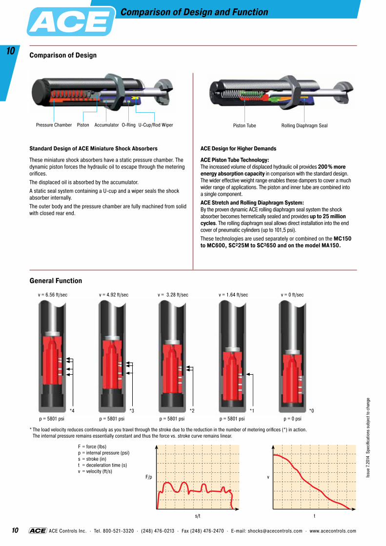
Standard Design of ACE Miniature Shock Absorbers
These miniature shock absorbers have a static pressure chamber. The dynamic piston forces the hydraulic oil to escape through the metering orifices.The displaced oil is absorbed by the accumulator.A static seal system containing a U-cup and a wiper seals the shock absorber internally. The outer body and the pressure chamber are fully machined from solid with closed rear end.
ACE Design for Higher Demands
ACE Piston Tube Technology: The increased volume of displaced hydraulic oil provides 200% more energy absorption capacity in comparison with the standard design. The wider effective weight range enables these dampers to cover a much wider range of applications. The piston and inner tube are combined into a single component.ACE Stretch and Rolling Diaphragm System: By the proven dynamic ACE rolling diaphragm seal system the shock absorber becomes hermetically sealed and provides up to 25 million cycles. The rolling diaphragm seal allows direct installation into the end cover of pneumatic cylinders (up to 101,5 psi).These technologies are used separately or combined on the MC150 to MC600, SC225M to SC2650 and on the model MA150.
Comparison of Design
*4 *3 *2 *1 *0
v = 6.56 ft/sec v = 4.92 ft/sec v = 3.28 ft/sec v = 1.64 ft/sec v = 0 ft/sec
p = 5801 psi p = 5801 psi p = 5801 psi p = 5801 psi p = 0 psi
* The load velocity reduces continously as you travel through the stroke due to the reduction in the number of metering orifices (*) in action. The internal pressure remains essentially constant and thus the force vs. stroke curve remains linear.
General Function
F = force (lbs)p = internal pressure (psi) s = stroke (in) t = deceleration time (s)v = velocity (ft/s)
F/p v
s/t t
Pressure Chamber Piston Accumulator O-Ring U-Cup/Rod Wiper Piston Tube Rolling Diaphragm Seal
Comparison of Design and Function

11
11
Issu
e 7.
2014
Spe
cific
atio
ns s
ubje
ct to
cha
nge
ACE Controls Inc. · Tel. 800-521-3320 · (248) 476-0213 · Fax (248) 476-2470 · E-mail: [email protected] · www.acecontrols.com
ACE shock absorbers provide linear deceleration and are therefore superior to other kinds of damping elements. It is easy to calculate around 90% of applications knowing only the following 5 parameters:
1. Weight to be decelerated W (lbs)2. Impact velocity at shock absorber VD (ft/sec)3. Propelling force F (lbs)4. Cycles per hour C (/hr)5. Number of absorbers in parallel nKey to symbols used
E1 Kinetic energy per cycle in-lbsE2 Propelling force energy per cycle in-lbsE3 Total energy per cycle (E1 + E2) in-lbs1 E4 Total energy per hour (E3 · C) in-lbs/hrWe Effective weight lbsW Weight to be decelerated lbsn Number of shock absorbers (in parallel)2 V Velocity at impact ft/sec2 VD Impact velocity at shock absorber ft/secω Angular velocity at impact °/secF Propelling force lbsC Cycles per hour /hrHp Motor power hp
3 ST Stall torque factor (normally 2.5) 1 to 3T Propelling torque lbs-inI Moment of Inertia lb-ft-sec2
g Acceleration due to gravity = 32.2 ft/s2 ft/s2
D Drop height excl. shock absorber stroke ins Shock absorber stroke inL/R/r Radius inQ Reaction force lbs� Coefficient of frictiont Deceleration time seca Deceleration ft/s2
α Side load angle °β Angle of incline °
1 All mentioned values of E4 in the capacity charts are only valid for room temperature. There are reduced values at higher temperature ranges.
2 V or VD is the final impact velocity of the weight. With accelerating motion the final impact velocity can be 1.5 to 2 times higher than the average. Please take this into account when calculating kinetic energy.
1 Weight without propelling force FormulaE1 = 0.186 · W · V2
E2 = F · sE3 = E1 + E2E4 = E3 · CWe = E3 /(0.186 · V2)
ExampleW = 500 lbsV = 3 ft/secFP = 0 lbss = 1 in (chosen)C = 500 /hr
E1 = 0.186 · 500 · 32 = 837 in-lbsE2 = 0 · 1 = 0 in-lbsE3 = 837 + 0 = 837 in-lbsE4 = 837 · 500 = 418,500 in-lbs/hrWe = 837/(0.186 · 32) = 500 lbsChosen from capacity chart: Model MC3325-3 self-compensating or MA3325 adjustable
2 Weight with propelling force ExampleW = 14 lbsV = 2.2 ft/secFP = 30 lbs s = 0.4 in (chosen)C = 100 /hr
E1 = 0.186 · 14 · 2.22 = 12.6 in-lbsE2 = 30 · 0.4 = 12 in-lbsE3 = 12.6 + 12 = 24.6 in-lbsE4 = 24.6 · 100 = 2,460 in-lbs/hrWe = 24.6/(0.186 · 2.22) = 27.3 lbsChosen from capacity chart: Model MC75-3 self-compensating1 V is the final impact velocity of the weight: With pneu- matically propelled systems this can be 1.5 to 2 times the average velocity. Please take this into account when calculating energy.
2.1 for vertical motion upwards 2.2 for vertical motion downwards
3 Weight with motor drive ExampleW = 2,100 lbsV = 1 ft/secHp = 2 hpST = 2.5 s = 2 in (chosen)C = 20 /hr
F = 550 · 2.5 · 2/1 = 2,750 lbsE1 = 0.186 · 2100 · 12 = 390.6 in-lbsE2 = 2,750 · 2 = 5,500 in-lbsE3 = 390.6 + 5,500 = 5,890.6 in-lbsE4 = 5,890.6 · 20 = 117,812 in-lbs/hrWe = 5,890.6/(0.186 · 12) = 31,670 lbsChosen from capacity chart:Model ML6450 or MC6450-4 self-compensating
FormulaE1 = 0.186 · W · V2
E2 = F · sE3 = E1 + E2E4 = E3 · CWe = E3 /(0.186 · V2)
E2 = (F – W) · sE2 = (F + W) · s
4 Weight on driven rollers ExampleW = 250 lbsV = 2.5 ft/sec� = 0.2 ins = 1 in (chosen)C = 180 /hr
F = 250 · .2 = 50 lbsE1 = 0.186 · 250 · 2.52 = 290.6 in-lbsE2 = 50 · 1 = 50 in-lbsE3 = 290.6 + 50 = 340.6 in-lbsE4 = 340.6 · 180 = 61,308 in-lbs/hrWe = 340.6/(0.186 · 2.52) = 293 lbsChosen from capacity chart: Model MA600 adjustable or SC650-3 self-compensating
FormulaF = W · � E1 = 0.186 · W · V2
E2 = F · sE3 = E1 + E2E4 = E3 · CWe = E3 /(0.186 · V2)
5 Swinging weight with propelling force
ExampleW = 20 lbsV = 12 ft/secT = 50 in-lbsR = 12 inL = 16 ins = 0.5 in (chosen)C = 700 /hr
E1 = 0.186 · 20 · 122 = 536 in-lbsE2 = 50 · 0.50/12 = 2.1 in-lbsE3 = 536 + 2.1 = 538.1 in-lbsE4 = 538.1 · 700 = 376,670 in-lbs/hrvD = 12 · 12/16 = 9 ft/secWe = 538.1/(0.186 · 92) = 35.7 lbsChosen from capacity chart:Model MC600 self-compensatingCheck the side load angle, tan α = s/R, with regard to “Max.Side Load Angle” in the capacity chart (see example 6.2)
FormulaE1 = 0.186 · W · V2
= 0.186 · I · ω2
E2 = T · s/RE3 = E1 + E2E4 = E3 · CVD = V · R/L = ω · RWe = E3 /(0.186 · VD2)
3 ST =̂ relation between starting torque and running torque of the motor (depending on the design)
In all the following examples the choice of shock absorbers made from the capacity chart is based upon the values of (E3), (E4), (We) and the desired shock absorber stroke (s).
FormulaF = 550 · ST · Hp/VE1 = 0.186 · W · V2
E2 = F · sE3 = E1 + E2E4 = E3 · cWe = E3 /(0.186 · V2)
Formula and Calculations
Note: Do not forget to include the rotational energy of motor, coupling and gearbox into calculation for E1.

12
12
Issu
e 7.
2014
Spe
cific
atio
ns s
ubje
ct to
cha
nge
ACE Controls Inc. · Tel. 800-521-3320 · (248) 476-0213 · Fax (248) 476-2470 · E-mail: [email protected] · www.acecontrols.com
6 Free falling weight ExampleW = 200 lbsD = 15 ins = 3 in (chosen)C = 60 /hr
6.1 Weight rolling/sliding down incline
FormulaE1 = 0.186 · W · (√5.4 · D)2
= 0.186 · W · VD2
E2 = (W · Sin(A)) · sE3 = E1 + E2E4 = E3 · CVD = √5.4 · DWe = E3 /(0.186 · VD2)
E2 = (F – W · Sin(A)) · sE2 = (F + W · Sin(A)) · s
6.1a propelling force up incline 6.1b propelling force down incline
9 Swinging arm with propelling force (uniform weight distribu-tion)
ExampleW = 500 lbsV = 6 ft/secF = 1,600 lbss = 1.91 in (chosen)RS = 24 inRf = 32 inL = 48 inC = 90 /hr
E1 = 0.063 · 500 · 62 = 1,134 in-lbsT = 1,600 · 32 = 51,200 lbs-inE2 = (51,200 · 1.91)/24 = 4,075 in-lbsE3 = 1,134 + 4,075 = 5,209 in-lbsE4 = 5,209 · 90 = 468,810 in-lbs/hrVD = (6 · 24)/48 = 3.0 ft/secWe = 5,209/(0.186 · 32) = 3,112 lbsChosen from capacity chart:Model MC4550-4 self-compensating
10 Weight lowered at controlled speed
ExampleW = 1,000 lbsV = 3 ft/secs = 0.91 in (chosen)C = 60 /hr
E1 = 0.186 · 1,000 · 32 = 1,674 in-lbsF = 1,000 lbsE2 = 1,000 · 0.91 = 910 in-lbsE3 = E1 + E2 = 1,674 + 910 = 2,584 in-lbsE4 = 2,584 · 60 = 155,040 in-lbs/hrWe = 2,584/(0.186 · 32) = 1,543 lbsChosen from capacity chart:Model MC4525-3 self-compensating
FormulaE1 = 0.186 · W · V2
E2 = F · sE3 = E1 + E2E4 = E3 · CWe = E3/(0.186 · V2)F = W
Reaction force Q [lbs] Q = (1.5 · E3)/s Stopping time t [s] t = (0.217 · s)/VD Deceleration rate a [ft/s2] a = (9 · VD2)/s
FormulaE1 = 0.063 · W · V2
= 6 · I · (ω · 0.01745)2
E2 = (T · s)/RS = (F · r · s)/RS
E3 = E1 + E2E4 = E3 · CVD = (V · RS)/L = RS · ω/688We = E3/(0.186 · VD2)T = F · Rf
8 Swinging arm with propelling torque (uniform weight distri-bution)
ExampleI = 3.895 lb-ft-sec2
ω = 70 °/secT = 15,000 lbs-ins = 1 in (chosen)L = 19 inR = 12 inC = 500 /hr
E1 = 6 · 3.895 · (70 · 0.01745)2 = 34.86 in-lbsE2 = 15,000 · 1/12 = 1,250 in-lbsE3 = 34.86 + 1,250 = 1,284.86 in-lbsE4 = 1,284.86 · 500 = 642,430 in-lbs/hrVD = 12 · 70/688 = 1.22 ft/secWe = 1,284.86/(0.186 · 1.222) = 4,641.1 lbsChosen from capacity chart: Model MC4525-4 self-compensating or MA4525 adjustableCheck the side load angle, tan α = s/RS, with regard to “Max.Side Load Angle” in the capacity chart (see example 6.2)
FormulaE1 = 0.063 · W · V2
= 6 · I · (ω · 0.01745)2
E2 = (T · s)/RE3 = E1 + E2E4 = E3 · CVD = (V · R)/L = R · ω/688We = E3/(0.186 · VD2)
7 Rotary index table with propelling torque
ExampleW = 195 lbsL = 20 inVS = 1.85 ft/secT = 1,700 lbs-inR = 15 inC = 60 /hrs = 0.75 in (chosen)
Wa = 195 · 202/(2 · 152) = 173.3 lbsF = 1,700/15 = 113.3 lbsE1 = 0.186 · 173.3 · 1.852 = 110.3 in-lbsE2 = 113.3 · 0.75 = 85 in-lbsE3 = 110.3 + 85 = 195.3 in-lbsE4 = 195.3 · 60 = 11,718 in-lbs/hrWe = 195.3/(0.186 · 1.852) = 306.8 lbsChosen from capacity chart:Model SC300-4 or MC225H self-compensatingCheck the side load angle, tan α = s/RS, with regard to “Max.Side Load Angle” in the capacity chart (see example 6.2)
FormulaE1 = 0.186 · Wa · VS2
E2 = F · sE3 = E1 + E2E4 = E3 · CVD = (VS · R)/L = ω · RWe = E3/(0.186 · V2)Wa = W · L2/(2 · R2)
V = R · ω/688F = T/R
6.2 Weight free falling about a pivot point
Check the side load angle, tan α = s/RS, with regard to “Max. Side Load Angle” in the capacity chart
tan α = s/RS
Side load angle from shock absorber axis
FormulaV = √(5.4 · D)E1 = 0.186 · W · V2
E2 = F · sE3 = E1 + E2E4 = E3 · CWe = E3 /(0.186 · V2)F = W
V = √(5.4 · 15) = 9 fpsE1 = 0.186 · 200 · 92 = 3,013.2 in-lbsE2 = 200 · 3 = 600 in-lbsE3 = 3,013.2 + 600 = 3613.2 in-lbsE4 = 3,613.2 · 60 = 216,792 in-lbs/hrWe = 3,613.2/(0.186 · 92) = 239.8 lbs
Chosen from capacity chart:Model MA4575 adjustable
Approximate values assuming correct adjustment. Add safety margin if necessary.(Exact values will depend upon actual application data and can be provided on request.)
Formula and Calculations
Calculation as per example 6.1except E2 = 0 E1 = 0.186 · W · (√5.4 · D)2
VD = (√5.4 · D) · RS/L

13
13
Issu
e 7.
2014
Spe
cific
atio
ns s
ubje
ct to
cha
nge
ACE Controls Inc. · Tel. 800-521-3320 · (248) 476-0213 · Fax (248) 476-2470 · E-mail: [email protected] · www.acecontrols.com
Effective Weight (We)
19 Wagon against 2 shock absorbers
ExampleW = 2,000 lbsF = 500 lbsV = 5 ft/secC = 20 /hr s = 1.91 in (chosen)
E1 = 0.093 · 2,000 · 52 = 4,650 in-lbsE2 = 500 · 1.91 = 955 in-lbsE3 = 4,650 + 955 = 5,605 in-lbsE4 = 5,605 · 20 = 112,100 in-lbs/hrVD = 5 · 0.5 = 2.5 ft/secWe = 5,605/(0.186 · 2.52) = 4,822 lbsChosen from capacity chart:Model MC4550-4 self-compensating
20 Wagon against wagon
21 Wagon against wagon 2 shock absorbers
FormulaE1 = 0.186 (W1 · W2)/
(W1 + W2) · (V1 + V2)2
E2 = F · sE3 = E1 + E2E4 = E3 · CVD = V1 + V2
We = E3/(0.186 · VD2)
FormulaE1 = 0.093 · W · V2
E2 = F · sE3 = E1 + E2E4 = E3 · CVD = V · 0.5We = E3/(0.186 · VD2)
ExampleW1 = 4,000 lbsV1 = 2 ft/secC = 30 /hr W2 = 8,000 lbsV2 = 1.2 ft/secF = 1,000 lbss = 2.91 in (chosen)
E1 = 0.186 (4,000 · 8,000)/ (4,000 + 8,000) · (2 + 1.2)2 = 5,079 in-lbs
E2 = 1,000 · 2.91 = 2,910 in-lbsE3 = 5,079 + 2,910 = 7,989 in-lbsE4 = 7,989 · 30 = 239,670 in-lbs/hrVD = 2 + 1.2 = 3.2 ft/sec We = 7,989/(0.186 · 3.22) = 4,194 lbsChosen from capacity chart:Model MC4575-4 self-compensating
Note: When using several shock absorbers in parallel, the values (E3), (E4) and (We) are divided according to the number of units used.
A Weight without propelling force
Formula We = W
B Weight with propelling force
Formula We = E3/(0.186 · VD2)
ExampleW = 100 lbsF = 200 lbsVD = V = 2 ft/secs = 2 in (chosen)E1 = 0.186 · W · V2 = 0.186 · 100 · 22 = 74.4 in-lbsE2 = F · s = 200 · 2 = 400 in-lbsE3 = E1 + E2 = 74.4 + 400 = 474.4 in-lbsWe = E3/(0.186 · VD2) = 474.4/(0.186 · 22) = 637.6 lbs
C Weight without propelling force direct against shock absorber
D Weight without propelling force with mechanical advantage
The effective weight (We) can either be the same as the actual weight (examples A and C), or it can be an imaginary weight representing a combination of the propelling force or lever action plus the actual weight (examples B and D).
Formula and Calculations
FormulaE1 = 0.093 (W1 · W2)/
(W1 + W2) · (V1 + V2)2
E2 = F · sE3 = E1 + E2E4 = E3 · CV = (V1 + V2)/2We = E3/(0.186 · VD2)
ExampleW1 = 4,000 lbsV1 = 2 ft/secC = 30 /hr W2 = 8,000 lbsV2 = 1.2 ft/secF = 1,000 lbss = 1.91 in (chosen)
E1 = 0.093 (4,000 · 8,000)/ (4,000 + 8,000) · (2 + 1.2)2 = 2,540 in-lbs
E2 = 1,000 · 1.91 = 1,910 in-lbsE3 = 2,540 + 1,910 = 4,450 in-lbsE4 = 4,450 · 30 = 133,500 in-lbs/hrvD = (2 + 1.2)/2 = 1.6 ft/sec We = 4,450/(0.186 · 1.62) = 9,346 lbsChosen from capacity chart:Model MC4550-4 self-compensating
ExampleW = 100 lbsVD = V = 2 ft/secE1 = 0.186 · W · V2 = 0.186 · 100 · 22 = 74.4 in-lbsE1 = E3 = 74.4 in-lbsWe = E3/(0.186 · VD2) = 74.4/(0.186 · 22) = 100 lbs
ExampleW = 50 lbsVD = V = 2 ft/secE1 = 0.186 · W · V2 = 0.186 · 50 · 22 = 37.2 in-lbsE1 = E3 = 37.2 in-lbsWe = E3/(0.186 · VD2) = 37.2/(0.186 · 22) = 50 lbs Formula
We = E3/(0.186 · VD2)
Formula We = W
ExampleW = 150 lbsV = 2 ft/secVS = VD = 0.5 ft/secE1 = 0.186 · W · V2 = 0.186 · 150 · 22 = 111.6 in-lbsE1 = E3 = 111.6 in-lbsWe = E3/(0.186 · VD2) = 111.6/(0.186 · 0.52) = 2,400 lbs

14
14
Issu
e 7.
2014
Spe
cific
atio
ns s
ubje
ct to
cha
nge
ACE Controls Inc. · Tel. 800-521-3320 · (248) 476-0213 · Fax (248) 476-2470 · E-mail: [email protected] · www.acecontrols.com
Shock Absorber Capacity ChartSelf-Compensating Shock Absorbers
Capacity ChartEnergy Capacity Effective Weight We
Self-CompensatingType Part Number
Stroke inches
E3 in lbs/Cycle
We min. lbs
We max. lbs
Page
MC5M-1 0.16 6 0.22 2.0 17MC5M-2 0.16 6 1.7 4.9 17MC5M-3 0.16 6 4.4 11.1 17MC9M-1 0.20 9 1.35 7.0 17MC9M-2 0.20 9 1.75 9.0 17MC10ML 0.20 11 0.75 6.0 17MC10MH 0.20 11 1.5 11 17MC30M-1 0.32 31 1.0 4.30 17MC30M-2 0.32 31 3.97 11.90 17MC30M-3 0.32 31 11.02 33.07 17MC25 0.26 20 4 12 17MC25H 0.26 20 10 30 17MC25L 0.26 20 1.5 5 17MC75-1 0.40 75 0.5 2.5 17MC75-2 0.40 75 2 14 17MC75-3 0.40 75 6 80 17MC75-4 0.40 75 55 160 17MC150 0.50 175 2 22 19MC150H 0.50 175 20 200 19MC150H2 0.50 175 150 450 19MC150H3 0.50 175 400 900 19MC225 0.50 360 5 55 19MC225H 0.50 360 50 500 19MC225H2 0.50 360 400 2,000 19MC225H3 0.50 360 1,800 4,000 19MC600 1.00 1,200 20 300 19MC600H 1.00 1,200 250 2,500 19MC600H2 1.00 1,200 880 5,000 19MC600H3 1.00 1,200 4,800 10,000 19SC25M-5 0.32 89 2.2 11 23SC25M-6 0.32 89 9 97 23SC25M-7 0.32 89 93 1,100 23SC75M-5 0.39 142 2.2 18 23SC75M-6 0.39 142 15 172 23SC75M-7 0.39 142 165 1,760 23SC190-0 0.63 225 1.54 8.82 21SC190-1 0.63 225 3 15 21SC190-2 0.63 225 8 40 21SC190-3 0.63 225 20 100 21SC190-4 0.63 225 50 225 21SC190M-5 0.47 274 4 35 23SC190M-6 0.47 274 29 309 23SC190M-7 0.47 274 300 3,400 23SC300-0 0.75 300 1.54 8.82 21SC300-1 0.75 300 3 18 21SC300-2 0.75 300 10 60 21SC300-3 0.75 300 30 180 21SC300-4 0.75 300 70 450 21SC300-5 0.59 650 25 100 23SC300-6 0.59 650 75 300 23SC300-7 0.59 650 200 400 23SC300-8 0.59 620 300 1,500 23SC300-9 0.59 620 700 4,300 23SC650-0 1.00 650 5.07 30.86 21SC650-1 1.00 650 17 100 21SC650-2 1.00 650 50 300 21SC650-3 1.00 650 150 900 21SC650-4 1.00 650 450 2,600 21SC650-5 0.91 1,860 50 250 23SC650-6 0.91 1,860 200 800 23SC650-7 0.91 1,860 700 2,400 23SC650-8 0.91 1,860 1,700 5,800 23SC650-9 0.91 1,860 4,000 14,000 23SC925-0 1.58 975 10 65 21SC925-1 1.58 975 30 200 21SC925-2 1.58 975 90 600 21SC925-3 1.58 975 250 1,600 21SC925-4 1.58 975 750 4,600 21MC3325-0 0.91 1,350 7 24 40MC3325-1 0.91 1,350 20 80 40MC3325-2 0.91 1,350 68 272 40MC3325-3 0.91 1,350 230 920 40MC3325-4 0.91 1,350 780 3,120 40MC3350-0 1.91 2,700 11 49 40MC3350-1 1.91 2,700 40 160 40MC3350-2 1.91 2,700 136 544 40MC3350-3 1.91 2,700 460 1,840 40MC3350-4 1.91 2,700 1,560 6,240 40
Capacity ChartEnergy Capacity Effective Weight We
Self-CompensatingType Part Number
Stroke inches
E3 in lbs/Cycle
We min. lbs
We max. lbs
Page
MC4525-0 0.91 3,000 15 60 42MC4525-1 0.91 3,000 50 200 42MC4525-2 0.91 3,000 170 680 42MC4525-3 0.91 3,000 575 2,300 42MC4525-4 0.91 3,000 1,950 7,800 42MC4550-0 1.91 6,000 29 119 42MC4550-1 1.91 6,000 100 400 42MC4550-2 1.91 6,000 340 1,360 42MC4550-3 1.91 6,000 1,150 4,600 42MC4550-4 1.91 6,000 3,900 15,600 42MC4575-0 2.91 9,000 44 176 42MC4575-1 2.91 9,000 150 600 42MC4575-2 2.91 9,000 510 2,040 42MC4575-3 2.91 9,000 1,730 6,920 42MC4575-4 2.91 9,000 5,850 23,400 42MC6450-0 1.91 15,000 77 309 44MC6450-1 1.91 15,000 300 1,200 44MC6450-2 1.91 15,000 1,020 4,080 44MC6450-3 1.91 15,000 3,460 13,840 44MC6450-4 1.91 15,000 11,700 46,800 44MC64100-0 3.91 30,000 154 617 44MC64100-1 3.91 30,000 600 2,400 44MC64100-2 3.91 30,000 2,040 8,160 44MC64100-3 3.91 30,000 6,920 27,680 44MC64100-4 3.91 30,000 23,400 93,600 44MC64150-0 5.91 45,000 220 1,014 44MC64150-1 5.91 45,000 900 3,600 44MC64150-2 5.91 45,000 3,060 12,240 44MC64150-3 5.91 45,000 10,380 41,520 44MC64150-4 5.91 45,000 35,100 140,400 44CA2X2-1 2.00 32,000 1,600 4,800 53CA2X2-2 2.00 32,000 4,000 12,000 53CA2X2-3 2.00 32,000 10,000 30,000 53CA2X2-4 2.00 32,000 25,000 75,000 53CA2X4-1 4.00 64,000 3,200 9,600 53CA2X4-2 4.00 64,000 8,000 24,000 53CA2X4-3 4.00 64,000 20,000 60,000 53CA2X4-4 4.00 64,000 50,000 150,000 53CA2X6-1 6.00 96,000 4,800 14,400 53CA2X6-2 6.00 96,000 12,000 36,000 53CA2X6-3 6.00 96,000 30,000 90,000 53CA2X6-4 6.00 96,000 75,000 225,000 53CA2X8-1 8.00 128,000 6,400 19,200 53CA2X8-2 8.00 128,000 16,000 48,000 53CA2X8-3 8.00 128,000 40,000 120,000 53CA2X8-4 8.00 128,000 100,000 300,000 53CA2X10-1 10.00 160,000 8,000 24,000 53CA2X10-2 10.00 160,000 20,000 60,000 53CA2X10-3 10.00 160,000 50,000 150,000 53CA2X10-4 10.00 160,000 125,000 375,000 53CA3X5-1 5.00 125,000 6,400 19,200 54CA3X5-2 5.00 125,000 16,000 48,000 54CA3X5-3 5.00 125,000 40,000 120,000 54CA3X5-4 5.00 125,000 100,000 300,000 54CA3X8-1 8.00 200,000 10,240 30,720 54CA3X8-2 8.00 200,000 25,600 76,800 54CA3X8-3 8.00 200,000 64,000 192,000 54CA3X8-4 8.00 200,000 160,000 480,000 54CA3X12-1 12.00 300,000 15,360 46,080 54CA3X12-2 12.00 300,000 38,400 115,200 54CA3X12-3 12.00 300,000 96,000 288,000 54CA3X12-4 12.00 300,000 240,000 720,000 54CA4X6-3 6.00 420,000 8,000 19,000 55CA4X6-5 6.00 420,000 19,000 41,000 55CA4X6-7 6.00 420,000 41,000 94,000 55CA4X8-3 8.00 560,000 11,000 25,000 55CA4X8-5 8.00 560,000 25,000 55,000 55CA4X8-7 8.00 560,000 55,000 125,000 55CA4X16-3 16.00 1,120,000 22,000 50,000 55CA4X16-5 16.00 1,120,000 50,000 110,000 55CA4X16-7 16.00 1,120,000 110,000 250,000 55

15
15
Issu
e 7.
2014
Spe
cific
atio
ns s
ubje
ct to
cha
nge
ACE Controls Inc. · Tel. 800-521-3320 · (248) 476-0213 · Fax (248) 476-2470 · E-mail: [email protected] · www.acecontrols.com
Shock Absorber Capacity ChartAdjustable Shock Absorbers
Capacity ChartMax. Energy Capacity, in-lbs Effective Weight We
Self-Contained AdjustableType Part Number
Stroke inches
E3 in lbs/Cycle
E4 in lbs/h
We min. lbs
We max. lbs
Page
MA30M 0.32 31 50,000 0.5 31 27MA50M 0.28 50 120,000 10 45 27MA35 0.40 35 53,000 13 125 27MA150 0.50 200 300,000 2 240 27MA225 0.75 300 400,000 5 500 27MA600 1.00 600 600,000 20 3,000 27AS3/8X1 1.00 600 600,000 10 1,250 29MA900 1.58 900 800,000 30 4,500 27MA3325 0.91 1,500 670,000 20 3,800 40ML3325 0.91 1,500 670,000 661 110,231 40MA3350 1.91 3,000 760,000 28 5,400 40ML3350 1.91 3,000 760,000 1,102 176,370 40MA4525 0.91 3,450 950,000 95 22,000 42ML4525 0.91 3,450 950,000 6,614 242,508 42MA4550 1.91 6,900 1,000,000 150 32,000 42ML4550 1.91 6,900 1,000,000 11,023 396,832 42MA4575 2.91 10,350 1,300,000 155 33,000 42ML6425 0.91 9,000 1,100,000 15,432 661,386 44MA6450 1.91 18,000 1,300,000 480 110,000 44ML6450 1.91 18,000 1,300,000 24,251 1,102,310 44MA64100 3.91 36,000 1,700,000 600 115,000 44MA64150 5.91 54,000 2,200,000 730 175,000 44A1½X2 2.00 21,000 3,200,000 430 70,000 52A1½X3½ 3.50 36,750 5,600,000 480 80,000 52A1½X5 5.00 52,500 8,000,000 500 90,000 52A1½X6½ 6.50 63,250 10,400,000 680 100,000 52A2X2 2.00 32,000 9,600,000 560 170,000 53A2X4 4.00 80,000 12,000,000 510 160,000 53A2X6 6.00 120,000 14,400,000 570 190,000 53A2X8 8.00 170,000 16,800,000 580 200,000 53A2X10 10.00 210,000 19,200,000 720 250,000 53A3X5 5.00 140,000 20,000,000 1,050 340,000 54A3X8 8.00 250,000 32,000,000 1,200 400,000 54A3X12 12.00 390,000 48,000,000 1,350 450,000 54

16
16
Issu
e 7.
2014
Spe
cific
atio
ns s
ubje
ct to
cha
nge
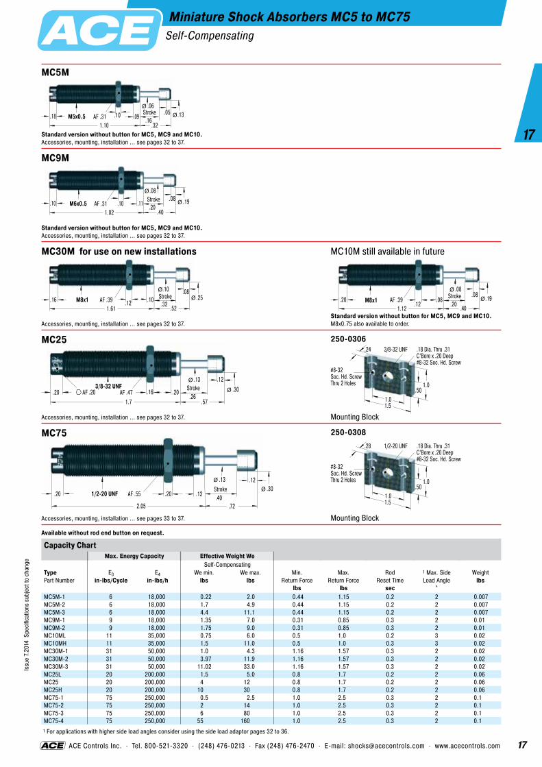
Miniature Shock Absorbers MC5 to MC75Self-Compensating
ACE miniature shock absorbers are mainte-nance-free, self-contained hydraulic compo-nents. The model range MC5 to MC75 have a very short overall length and a low return force. The shock absorber is filled with a tem- perature stable oil and has an integrated positive stop. They are ideally suited for small, fast, handling equipment, rotary actuators, pick and place mechanisms and similar small automation equipment. A wide choice of metering hardnesses enable these units to cover applications with effective weights ranging from 0.66 lbs to 158.73 lbs.
Elastomer Insert(MC25 and MC75)
Piston Rod
Positive Stop
Main Bearing
Accumulator
Piston
Return Spring
Pressure Chamber
Outer Body
Slot
Rod Seals
Locknut
Impact velocity range: MC5M: 1.89 to 11.58 ft/sec MC9M: 0.5 to 6 ft/sec MC10: 0.5 to 5 ft/sec MC25: 0.5 to 8 ft/sec MC30M & MC30M-Z: 2.2 to 12.9 ft/sec MC75: 0.5 to 12 ft/secMaterial: Shock absorber body: Steel with black oxide finish or nitride hardened. Accessories: Steel with black oxide finish or nitride hardened. Piston rod: Hardened stainless steel. Locknut MC5 and MC9: Aluminium.E4 capacity rating: (max. energy per hour, in-lbs/h) If your application exceeds the tabulated E4 figures consider additional cooling i.e. cylinder exhaust air etc. Ask ACE for further details.Mounting: In any position. If precise end position is required, con sider use of the optional stop collar.Operating temperature range: 32 °F to 150 °FOn request: Corrosion-resistant Weartec Plus outer tube coating is standard. Other coatings and construction materials are available upon request.
17
17
Issu
e 7.
2014
Spe
cific
atio
ns s
ubje
ct to
cha
nge
ACE Controls Inc. · Tel. 800-521-3320 · (248) 476-0213 · Fax (248) 476-2470 · E-mail: [email protected] · www.acecontrols.com
Miniature Shock Absorbers MC5 to MC75Self-Compensating
.18 .10 Stroke .05AF .31 .16
1.10M5x0.5
.32.09 .13
.06ØØ
MC5M
Standard version without button for MC5, MC9 and MC10.Accessories, mounting, installation ... see pages 32 to 37.
.10 .10Stroke .08
AF .31 .201.02
M6x0.5.40
.11 .19
.08Ø
Ø
MC9M
Standard version without button for MC5, MC9 and MC10.Accessories, mounting, installation ... see pages 32 to 37.
.20.12
Stroke.08
.08AF .39
.201.12
.19M8x1.40
.08
ØØ
MC10M still available in future
Standard version without button for MC5, MC9 and MC10. M8x0.75 also available to order.
.16 .12Stroke
.10 .08AF .39
.321.61
.25M8x1.52
.10
ØØ
MC30M for use on new installations
Accessories, mounting, installation ... see pages 32 to 37.
.20Stroke
.13 .12
AF .47.26
1.7
.303/8-32 UNF
.57.16 .20AF .20
Ø
Ø
MC25
Accessories, mounting, installation ... see pages 32 to 37.
250-0306
Mounting Block1.5
1.0
3/8-32 UNF .18 Dia. Thru .31C’Bore x .20 Deep#8-32 Soc. Hd. Screw
1.0
.24
#8-32 Soc. Hd. ScrewThru 2 Holes
.50
.20Stroke
.13 .12
AF .55 .402.05
.301/2-20 UNF
.72
.20 .12
Ø
Ø
MC75
Accessories, mounting, installation ... see pages 33 to 37.
250-0308
Mounting Block
1.5
1.0
1/2-20 UNF .18 Dia. Thru .31C’Bore x .20 Deep#8-32 Soc. Hd. Screw
1.0
.28
#8-32 Soc. Hd. ScrewThru 2 Holes
.50
Available without rod end button on request.
Capacity ChartMax. Energy Capacity Effective Weight We
Self-CompensatingType Part Number
E3 in-lbs/Cycle
E4 in-lbs/h
We min. lbs
We max. lbs
Min. Return Force
lbs
Max. Return Force
lbs
Rod Reset Time
sec
1 Max. Side Load Angle
°
Weight lbs
MC5M-1 6 18,000 0.22 2.0 0.44 1.15 0.2 2 0.007MC5M-2 6 18,000 1.7 4.9 0.44 1.15 0.2 2 0.007MC5M-3 6 18,000 4.4 11.1 0.44 1.15 0.2 2 0.007MC9M-1 9 18,000 1.35 7.0 0.31 0.85 0.3 2 0.01MC9M-2 9 18,000 1.75 9.0 0.31 0.85 0.3 2 0.01MC10ML 11 35,000 0.75 6.0 0.5 1.0 0.2 3 0.02MC10MH 11 35,000 1.5 11.0 0.5 1.0 0.3 3 0.02MC30M-1 31 50,000 1.0 4.3 1.16 1.57 0.3 2 0.02MC30M-2 31 50,000 3.97 11.9 1.16 1.57 0.3 2 0.02MC30M-3 31 50,000 11.02 33.0 1.16 1.57 0.3 2 0.02MC25L 20 200,000 1.5 5.0 0.8 1.7 0.2 2 0.06MC25 20 200,000 4 12 0.8 1.7 0.2 2 0.06MC25H 20 200,000 10 30 0.8 1.7 0.2 2 0.06MC75-1 75 250,000 0.5 2.5 1.0 2.5 0.3 2 0.1MC75-2 75 250,000 2 14 1.0 2.5 0.3 2 0.1MC75-3 75 250,000 6 80 1.0 2.5 0.3 2 0.1MC75-4 75 250,000 55 160 1.0 2.5 0.3 2 0.1
1 For applications with higher side load angles consider using the side load adaptor pages 32 to 36.

18
18
Issu
e 7.
2014
Spe
cific
atio
ns s
ubje
ct to
cha
nge
Miniature Shock Absorbers MC150 to MC600Self-Compensating
Impact velocity range: 0.26 to 19.7 ft/sec MC150H3: 0.32 to 1.53 ft/sec MC225H3: 0.22 to 1.03 ft/sec MC600H3: 0.25 to 1.15 ft/secMaterial: Shock absorber body: Nitride hardened steel. Piston rod: Hardened stainless steel. Accessories: Steel with black oxide finish or nitride hardened. Rolling diaphragm seal: EPDM.Note: Local contamination can effect the rolling seal and reduce the lifetime. PLease contact ACE for a suitable solution.E4 capacity rating: (max. energy per hour, in-lbs/h) If your application exceeds the tabulated E4 figures consider additional cooling i.e. cylinder exhaust air etc. Ask ACE for further details.Mounting: In any position. If precise end position is required, con sider use of the optional stop collar.Operating temperature range: 32 °F to 150 °FOn request: Corrosion-resistant Weartec Plus outer tube coating is standard. Other coatings and construction materials are available upon request.
Piston Rod
Outer Body
Self-RetainingMain Bearing
Locknut
Diaphragm Locator
O-Ring
Piston with IntegralPositive Stop
InternalHex Socket
Rolling Diaphragm Seal
Pressure Chamberwith Metering Orifices
“Rolling diaphragm seal system –up to 25 million cycles
possible !”
ACE miniature shock absorbers are mainte-nance-free, self-contained hydraulic compo-nents. The hermetically sealed rolling diaphragm seal system used on the MC150 to MC600 model range provides the highest possible cycle lifetime; up to 25 million cycles being achievable. All models incorporate an integral positive stop. The rolling diaphragm seal provides an extremely low rod return force. These models can be directly mounted into the end cover of pneumatic cylinders (up to 101.53 psi) to provide superior end damping compared to normal cylinder cushions. By adding the op- tional side load adaptor it is possible to accept side loads up to 25° from the axis. The wide range of models available ensure a seamless range of operation on applications with effective weights ranging from 2 lbs up to 10,000 lbs by selecting the appropriate model.

19
19
Issu
e 7.
2014
Spe
cific
atio
ns s
ubje
ct to
cha
nge
ACE Controls Inc. · Tel. 800-521-3320 · (248) 476-0213 · Fax (248) 476-2470 · E-mail: [email protected] · www.acecontrols.com
Miniature Shock Absorbers MC150 to MC600Self-Compensating
9/16-18 UNF.28 .31 AF .87 .50Stroke
.19
2.72 .69
AF .25
Ø
MC150
Accessories, mounting, installation ... see pages 33 to 37.
250-0318
Mounting Block
1.81
1.37
9/16-18 UNF .21 Dia. Thru .32C’Bore x .32 Deep#10-32 Soc. Hd. Screw
1.38
.50
.31
.69
1.00
#10-32 Soc. Hd. ScrewThru 4 Holes
250-0095
Steel/Urethane Button
.46
.18.48
.19ØØ
250-0753
Nylon Button E3 max = 123.91 lbs
.47
.18.37
.19Ø
Ø
3/4-16 UNF.28 .24 AF .99 .50Stroke
.25
3.12 .69
AF .32
Ø
MC225
Accessories, mounting, installation ... see pages 34 to 37.
250-0401
Mounting Block2.00
1.50
3/4-16 UNF .22 Dia. Thru .33C’Bore x .45 Deep#10-32 Soc. Hd. Screw
1.50
.56
.31
.75
1.12
#10-32 Soc. Hd. ScrewThru 4 Holes
250-0097
Steel/Urethane Button
.66
.18.52
.25ØØ
250-0754
Nylon Button E3 max = 292.07 lbs
.66
.19.35
.25Ø
Ø
1-12 UNF.28 .24 AF 1.23 1.00Stroke
.31
4.34 1.24
AF .38
Ø
MC600
Accessories, mounting, installation ... see pages 34 to 37.
250-0402
Mounting Block
2.00
1.50
1-12 UNF .22 Dia. Thru .33C’Bore x .45 Deep#10-32 Soc. Hd. Screw
1.50
.56
.31
.75
1.12
#10-32 Soc. Hd. ScrewThru 4 Holes
250-0099
Steel/Urethane Button
.89
.22.57
.31ØØ
250-0755
Nylon Button E3 max = 601.85 lbs
.90
.20.42
.31ØØ
Capacity ChartMax. Energy Capacity Effective Weight We
Self-CompensatingType Part Number
E3 in-lbs/Cycle
E4 in-lbs/h
We min. lbs
We max. lbs
Min. Return Force
lbs
Max. Return Force
lbs
Rod Reset Time
sec
1 Max. Side Load Angle
°
Weight lbs
MC150 175 300,000 2 22 0.70 1.20 0.4 4 0.12MC150H 175 300,000 20 200 0.70 1.20 0.4 4 0.12MC150H2 175 300,000 150 450 0.70 1.20 0.4 4 0.12MC150H3 175 300,000 400 900 0.70 1.20 1.0 4 0.12MC225 360 400,000 5 55 1.00 1.50 0.3 4 0.34MC225H 360 400,000 50 500 1.00 1.50 0.3 4 0.34MC225H2 360 400,000 400 2,000 1.00 1.50 0.3 4 0.34MC225H3 360 400,000 1,800 4,000 1.00 1.50 0.3 4 0.34MC600 1,200 600,000 20 300 1.00 2.00 0.6 2 0.57MC600H 1,200 600,000 250 2,500 1.00 2.00 0.6 2 0.57MC600H2 1,200 600,000 880 5,000 1.00 2.00 0.6 2 0.57MC600H3 1,200 600,000 4,800 10,000 1.00 2.00 0.6 2 0.57
1 For applications with higher side load angles consider using the side load adaptor pages 33 to 36.

20
20
Issu
e 7.
2014
Spe
cific
atio
ns s
ubje
ct to
cha
nge
Miniature Shock Absorbers SC190 to SC925Soft-Contact and Self-Compensating
ACE miniature shock absorbers are maintenance-free, self-contained hydraulic components. The SC-Series provide dual performance benefits. They provide “soft contact” deceleration where initial impact reaction forces are very low with the advan-tages of self-compensation to cope with changing input energy conditions without ad- justment. They have long stroke lengths to provide smooth deceleration and low reaction forces. They have an integrated mechanical stop and are ideal for use on handling equip- ment, linear transfers, rodless cylinders and pneumatic pick and place systems etc. The overlapping operating ranges enable the SC series to handle effective weights ranging 1.5 lbs up to 4,600 lbs. With the optional side load adaptor fitted they can cope with the side loads up to 25°.
Impact velocity range: 0.5 to 12 ft/secMaterial: Shock absorber body: Nitride hardened steel. Accessories: Steel with black oxide finish or nitride hardened. Piston rod: Hardened stainless steel.E4 capacity rating: (max. energy per hour, in-lbs/h) If your application exceeds the tabulated E4 figures consider additional cooling i.e. cylinder exhaust air etc. Ask ACE for further details.Mounting: In any position. If precise end position is required, con sider use of the optional stop collar.Operating temperature range: 32 °F to 150 °FOn request: Corrosion-resistant Weartec Plus outer tube coating is standard. Other coatings and construction materials are available upon request.
Positive Stop
Main Bearing
Accumulator
PistonPiston Check Valve
Pressure Chamber with Metering Orifices
Return Spring
Outer Body
Piston Rod
Rod Button
Rod Seals
Locknut

21
21
Issu
e 7.
2014
Spe
cific
atio
ns s
ubje
ct to
cha
nge
ACE Controls Inc. · Tel. 800-521-3320 · (248) 476-0213 · Fax (248) 476-2470 · E-mail: [email protected] · www.acecontrols.com
Miniature Shock Absorbers SC190 to SC925Soft-Contact and Self-Compensating
.16.18
.479/16-18 UNF.28 AF1/2 .313.44
AF .87 .631.06
Stroke.16
Ø
Ø
SC190
Accessories, mounting, installation ... see pages 33 to 37.
250-0318
Mounting Block
1.81
1.37
9/16-18 UNF .21 Dia. Thru .32C’Bore x .32 Deep#10-32 Soc. Hd. Screw
1.38
.50
.31
.69
1.00
#10-32 Soc. Hd. ScrewThru 4 Holes
.19.18
.663/4-16 UNF.28 AF11/16 .243.44
AF .99 .751.18
Stroke.07Ø
Ø
SC300
Accessories, mounting, installation ... see pages 33 to 37.
250-0401
Mounting Block
2.00
1.50
3/4-16 UNF .22 Dia. Thru .33C’Bore x .45 Deep#10-32 Soc. Hd. Screw
1.50
.56
.31
.75
1.12
#10-32 Soc. Hd. ScrewThru 4 Holes
.25.18
.901-12 UNF.28 AF7/8 .244.19
AF 1.23 1.001.43
Stroke.08Ø
Ø
SC650
Accessories, mounting, installation ... see pages 33 to 37.
250-0402
Mounting Block
2.00
1.50
1-12 UNF .22 Dia. Thru .33C’Bore x .45 Deep#10-32 Soc. Hd. Screw
1.50
.56
.31
.75
1.12
#10-32 Soc. Hd. ScrewThru 4 Holes
250-0402
Mounting Block
2.00
1.50
1-12 UNF .22 Dia. Thru .33C’Bore x .45 Deep#10-32 Soc. Hd. Screw
1.50
.56
.31
.75
1.12
#10-32 Soc. Hd. ScrewThru 4 Holes
.25.18
.901-12 UNF.28 AF7/8 .245.43
AF1.23 1.582.01
Stroke.08Ø
Ø
SC925
Accessories, mounting, installation ... see pages 33 to 37.
Available without rod end button on request.
Capacity ChartMax. Energy Capacity Effective Weight We
Soft-Contact Self-CompensatingType Part Number
E3 in-lbs/Cycle
E4 in-lbs/h
We min. lbs
We max. lbs
We min. lbs
We max. lbs
Min. Return Force lbs
Max. Return Force lbs
Rod Reset Time sec
1 Max. Side Load Angle
°
Weight lbs
SC190-0 225 300,000 – – 1.54 8.82 0.9 1.9 0.25 5 0.18SC190-1 225 300,000 5 13 3 15 0.9 1.9 0.25 5 0.18SC190-2 225 300,000 12 36 8 40 0.9 1.9 0.25 5 0.18SC190-3 225 300,000 30 90 20 100 0.9 1.9 0.25 5 0.18SC190-4 225 300,000 75 200 50 225 0.9 1.9 0.25 5 0.18SC300-0 300 400,000 – – 1.54 4 1.05 2.15 0.1 5 0.25SC300-1 300 400,000 5 15 3 18 1.05 2.15 0.1 5 0.25SC300-2 300 400,000 15 50 10 60 1.05 2.15 0.1 5 0.25SC300-3 300 400,000 50 150 30 180 1.05 2.15 0.1 5 0.25SC300-4 300 400,000 150 400 70 450 1.05 2.15 0.1 5 0.25SC650-0 650 600,000 – – 5.07 30.86 2.4 6.87 0.2 5 0.67SC650-1 650 600,000 24 80 17 100 2.4 6.87 0.2 5 0.67SC650-2 650 600,000 75 250 50 300 2.4 6.87 0.2 5 0.67SC650-3 650 600,000 240 800 150 900 2.4 6.87 0.2 5 0.67SC650-4 650 600,000 800 2,400 450 2,600 2.4 6.87 0.2 5 0.67SC925-0 975 800,000 18 55 10 65 2.4 7.4 0.4 5 0.87SC925-1 975 800,000 50 160 30 200 2.4 7.4 0.4 5 0.87SC925-2 975 800,000 130 460 90 600 2.4 7.4 0.4 5 0.87SC925-3 975 800,000 400 1,350 250 1,600 2.4 7.4 0.4 5 0.87SC925-4 975 800,000 1200 4,300 750 4,600 2.4 7.4 0.4 5 0.87
1 For applications with higher side load angles consider using the side load adaptor pages 33 to 36.

22
22
Issu
e 7.
2014
Spe
cific
atio
ns s
ubje
ct to
cha
nge
Miniature Shock Absorbers SC²25 to SC²650Self-Compensating
Impact velocity range: SC25M5: 2.9 to 14.7 ft/sec SC25M6: 0.99 to 7.3 ft/sec SC25M7: 0.29 to 2.3 ft/sec SC75M5: 2.9 to 18.6 ft/sec SC75M6: 0.94 to 7.1 ft/sec SC75M7: 0.29 to 2.1 ft/sec SC190M5: 2.9 to 18.3 ft/sec SC190M6: 0.98 to 7.1 ft/sec SC190M7: 0.29 to 2.2 ft/sec SC300, SC650: 0.30 to 12.0 ft/sec Material: Shock absorber body: Nitride hardened steel. Accessories: Steel with black oxide finish or nitride hardened. Piston rod: Hardened stainless steel.Mounting: In any position. If precise end position is required, con sider use of the optional stop collar.Operating temperature range: 32 °F to 150 °FOn request: Corrosion-resistant Weartec Plus outer tube coating is standard. Other coatings and construction materials are available upon request.
ACE miniature shock absorbers are mainte-nance-free, self-contained hydraulic compo-nents. The design of the SC²-Series units combines the piston and inner tube into a single component and provides more than double the energy capacity of previous units in the same envelope size. They have an integrated mechanical stop and are ideal for use on handling equipment, linear transfers, rodless cylinders, pneumatic pick and place systems and rotation modules etc. The smaller sizes up to type SC²190, have a dynamic membrane seal which allows direct installation into the end cover of pneumatic cylinders (for end position damping max. 101.53 psi). The greatly increased energy capacity coupled with overlapping effective weight ranges covering from 2.2 lbs up to 13,999 lbs makes the SC2-Series units ideal for rotary actuators. With the optional side load adaptor fitted they can cope with the side loads up to 25°.
Rolling Diaphragm Seal(Type SC2190)
Self-Retaining Main Bearing
Piston Tube
Piston Check Valve
Pressure Chamber with Metering OrificesReturn Spring
Outer Body
Piston Rodwith IntegratedPositive Stop
Rod Button
Locknut
“Combined piston and inner tube – increased energy capacity up to 200%!”

23
23
Issu
e 7.
2014
Spe
cific
atio
ns s
ubje
ct to
cha
nge
ACE Controls Inc. · Tel. 800-521-3320 · (248) 476-0213 · Fax (248) 476-2470 · E-mail: [email protected] · www.acecontrols.com
Miniature Shock Absorbers SC²25 to SC²650Self-Compensating
.12
M10x1.20 AF .27 .162.84
AF .47 .32.43
StrokeØ
SC25M
Accessories, mounting, installation ... see pages 32 to 37.
250-0307
Mounting Block
1.50
.98
.20
M10x1
.18.98
Ø
.24
.16
M12x1.23 AF .31 .203.07
AF .55 .39.55
StrokeØ
SC75M
Accessories, mounting, installation ... see pages 33 to 37.
250-0309
Mounting Block
1.50
.98
.20
M12x1
.18.98
Ø
.24
.19
M14x1.5.20 AF .39 .243.03
AF .66 .47.67
StrokeØ
SC190M
M14x1 also available to special orderAccessories, mounting, installation ... see pages 33 to 37.
250-0352
Mounting Block
1.77
1.14
.20
M14x1.5
.18
1.38
Ø
.31
.18.663/4-16 UNF.28 AF7/8 .24
3.13AF .99 .59
1.02
Stroke.25
.07Ø
Ø
SC300
Accessories, mounting, installation ... see pages 34 to 37.
.18.901-12 UNF.28 AF7/8 .39
4.18AF 1.18 .91
1.33
Stroke.38
.07Ø
Ø
SC650
Accessories, mounting, installation ... see pages 34 to 37.
Capacity ChartMax. Energy Capacity Effective Weight We
Soft HardType
E3 in-lbs/Cycle
E4 in-lbs/h
-5min. max.
lbs
-6min. max.
lbs
-7min. max.
lbs
-8min. max.
lbs
-9min. max.
lbs
Min. Return Force lbs
Max. Return Force lbs
Rod Reset Time sec
1 Max. Side Load Angle
°
Weight lbs
SC25M 89 142,000 2.2 - 11.0 9 - 97 93 - 1,100 – – 0.90 3.07 0.3 2 0.06SC75M 142 266,000 2.2 - 18.0 15 - 272 165 - 1,760 – – 0.69 3.40 0.4 2 0.10SC190M 274 443,000 4.4 - 35.2 29 - 309 300 - 3,400 – – 0.97 5.57 0.4 2 0.13SC300 650 400,000 25.0 - 100.0 75 - 300 200 - 400 300 - 1,500 700 - 4,300 1.70 4.00 0.2 5 0.33SC650 1,860 600,000 50.0 - 250.0 200 - 800 700 - 2,400 1,700 - 5,800 4,000 - 14,000 2.40 7.30 0.3 5 0.76
1 For applications with higher side load angles consider using the side load adaptor pages 32 to 36.
250-0401
Mounting Block
2.00
1.50
3/4-16 UNF .22 Dia. Thru .33C’Bore x .45 Deep#10-32 Soc. Hd. Screw
1.50
.56
.31
.75
1.12
#10-32 Soc. Hd. ScrewThru 4 Holes
250-0402
Mounting Block
2.00
1.50
1-12 UNF .22 Dia. Thru .33C’Bore x .45 Deep#10-32 Soc. Hd. Screw
1.50
.56
.31
.75
1.12
#10-32 Soc. Hd. ScrewThru 4 Holes

24
24
Issu
e 7.
2014
Spe
cific
atio
ns s
ubje
ct to
cha
nge
Miniature Shock Absorbers SC25-HC to SC650-HCHigh-Cycle Series, Self-Compensating
Rolling Diaphragm Seal(Type SC2190)
Self-Retaining Main Bearing
Piston Tube
Piston Check Valve
Pressure Chamber with Metering OrificesReturn Spring
Outer Body
Piston Rodwith IntegratedPositive Stop
Rod Button
Locknut
“Combined piston and inner tube – increased energy capacity up to 200%!”
ACE Controls SC25 to SC650-HC High-Cycle shock absorbers are engineered for high-speed equipment applications. These rugged perform-ers are ideal for the packaging industry. They offer a short stroke, quick time through stroke and quick rod-ready time. In addition, these dependable self-compensating miniatures are capable of rapid repeat strokes. The result is faster cycling for your equipment and gains in production time for you.Applications include: Packaging equipment, slides, rotary actuators, small and medium robotics, machine tools, pick & place operations and more.
Positive stop: Integral mechanical stop built into shock absorber.Impact velocity range: SC25M5-HC: 0.98 to 6.98 ft/sec SC25M6-HC: 0.33 to 3.45 ft/sec SC25M7-HC: 0.09 to 1.07 ft/sec SC75M5-HC: 1.49 to 13.52 ft/sec SC75M6-HC: 0.48 to 5.18 ft/sec SC75M7-HC: 0.15 to 1.56 ft/sec SC190M5-HC: 1.63 to 14.60 ft/sec SC190M6-HC: 0.55 to 5.69 ft/sec SC190M7-HC: 0.16 to 1.76 ft/sec SC300-5-HC: 1.39 to 8.79 ft/sec SC300-6-HC: 0.80 to 5.07 ft/sec SC300-7-HC: 0.69 to 3.11 ft/sec SC300-8-HC: 0.36 to 2.54 ft/sec SC300-9-HC: 0.21 to 1.66 ft/sec SC650-5-HC: 1.60 to 11.34 ft/sec SC650-6-HC: 0.90 to 5.67 ft/sec SC650-7-HC: 0.52 to 3.03 ft/sec SC650-8-HC: 0.33 to 1.95 ft/sec SC650-9-HC: 0.21 to 1.27 ft/sec Operating fluid: SF 96-500Material: Shock absorber body: Steel with Weartec Plus finish. Piston rod: Hardened stainless steel.Mounting: In any position. If precise end position is required, con sider use of the optional stop collar.Operating temperature range: 32 °F to 150 °F

25
25
Issu
e 7.
2014
Spe
cific
atio
ns s
ubje
ct to
cha
nge
ACE Controls Inc. · Tel. 800-521-3320 · (248) 476-0213 · Fax (248) 476-2470 · E-mail: [email protected] · www.acecontrols.com
Miniature Shock Absorbers SC25-HC to SC650-HCHigh-Cycle Series, Self-Compensating
.12
M10x1.20 AF .27 .162.84
AF .47 .16.28
StrokeØ
SC25M-HC
Accessories, mounting, installation ... see pages 32 to 37.
250-0307
Mounting Block
1.50
.98
.20
M10x1
.18.98
Ø
.24
.16
M12x1.23 AF .31 .203.07
AF .55 .20.36
StrokeØ
SC75M-HC
Accessories, mounting, installation ... see pages 33 to 37.
250-0309
Mounting Block
1.50
.98
.20
M12x1
.18.98
Ø
.24
.19
M14x1.5.20 AF .39 .243.03
AF .66 .30.50
StrokeØ
SC190M-HC
M14x1 also available to special orderAccessories, mounting, installation ... see pages 33 to 37.
250-0352
Mounting Block
1.77
1.14
.20
M14x1.5
.18
1.38
Ø
.31
.18.663/4-16 UNF.28 AF7/8 .24
3.13AF .99 .33
.76
Stroke.25
.07Ø
Ø
SC300-HC
Accessories, mounting, installation ... see pages 34 to 37.
.18.901-12 UNF.28 AF7/8 .39
4.18AF 1.18 .59
1.02
Stroke.38
.07Ø
Ø
SC650-HC
Accessories, mounting, installation ... see pages 34 to 37.
Capacity ChartMax. Energy Capacity Effective Weight We
Soft HardType
E3 in-lbs/Cycle
E4 in-lbs/h
-5min. max.
lbs
-6min. max.
lbs
-7min. max.
lbs
-8min. max.
lbs
-9min. max.
lbs
Min. Return Force lbs
Max. Return Force lbs
Rod Reset Time sec
1 Max. Side Load Angle
°
Weight lbs
SC25M-HC 20 142,000 2.2 - 11.0 9 - 97 93 - 1,100 – – 1.98 3.08 0.2 2 0.06SC75M-HC 75 266,000 2.2 - 18.0 15 - 272 165 - 1,760 – – 1.94 3.4 0.3 2 0.10SC190M-HC 175 443,000 4.4 - 35.2 29 - 309 300 - 3,400 – – 2.67 5.57 0.3 2 0.13SC300-HC 650 400,000 25.0 - 100.0 75 - 300 200 - 400 300 - 1,500 700 - 4,300 2.63 3.91 0.2 5 0.33SC650-HC 1,200 600,000 50.0 - 250.0 200 - 800 700 - 2,400 1,700 - 5,800 4,000 - 14,000 4.94 8.30 0.2 5 0.76
1 For applications with higher side load angles consider using the side load adaptor pages 32 to 36.
250-0401
Mounting Block
2.00
1.50
3/4-16 UNF .22 Dia. Thru .33C’Bore x .45 Deep#10-32 Soc. Hd. Screw
1.50
.56
.31
.75
1.12
#10-32 Soc. Hd. ScrewThru 4 Holes
250-0402
Mounting Block
2.00
1.50
1-12 UNF .22 Dia. Thru .33C’Bore x .45 Deep#10-32 Soc. Hd. Screw
1.50
.56
.31
.75
1.12
#10-32 Soc. Hd. ScrewThru 4 Holes
26
26
Issu
e 7.
2014
Spe
cific
atio
ns s
ubje
ct to
cha
nge
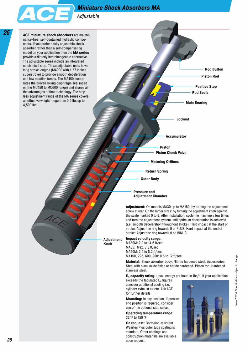
Miniature Shock Absorbers MA Adjustable
Adjustment: On models MA30 up to MA150: by turning the adjustment screw at rear. On the larger sizes: by turning the adjustment knob against the scale marked 0 to 9. After installation, cycle the machine a few times and turn the adjustment system until optimum deceleration is achieved (i.e. smooth deceleration throughout stroke). Hard impact at the start of stroke: Adjust the ring towards 9 or PLUS. Hard impact at the end of stroke: Adjust the ring towards 0 or MINUS.Impact velocity range: MA30M: 2.2 to 14.6 ft/sec MA35: Max. 3.3 ft/sec MA50M: 2.4 to 5.2 ft/sec MA150, 225, 600, 900: 0.5 to 12 ft/secMaterial: Shock absorber body: Nitride hardened steel. Accessories: Steel with black oxide finish or nitride hardened. Piston rod: Hardened stainless steel.E4 capacity rating: (max. energy per hour, in-lbs/h) If your application exceeds the tabulated E4 figures consider additional cooling i.e. cylinder exhaust air etc. Ask ACE for further details.Mounting: In any position. If precise end position is required, con sider use of the optional stop collar. Operating temperature range: 32 °F to 150 °FOn request: Corrosion-resistant Weartec Plus outer tube coating is standard. Other coatings and construction materials are available upon request.
Piston Rod
Positive Stop
Main Bearing
Accumulator
PistonPiston Check Valve
Metering Orifices
AdjustmentKnob
Pressure and Adjustment Chamber
Rod Seals
Return Spring
Outer Body
Rod Button
Locknut
ACE miniature shock absorbers are mainte-nance-free, self-contained hydraulic compo-nents. If you prefer a fully adjustable shock absorber rather than a self-compensating model on your application then the MA series provide a directly interchangeable alternative. The adjustable series include an integrated mechanical stop. These adjustable units have long stroke lengths (MA900 with 1.57 inches superstroke) to provide smooth deceleration and low reaction forces. The MA150 incorpo-rates the proven rolling diaphragm seal (used on the MC150 to MC600 range) and shares all the advantages of that technology. The step- less adjustment range of the MA series covers an effective weight range from 0.5 lbs up to 4,500 lbs.

27
27
Issu
e 7.
2014
Spe
cific
atio
ns s
ubje
ct to
cha
nge
ACE Controls Inc. · Tel. 800-521-3320 · (248) 476-0213 · Fax (248) 476-2470 · E-mail: [email protected] · www.acecontrols.com
Miniature Shock Absorbers MAAdjustable
.16 StrokeAF .47.281.86 .69
.12.30M10x1.20
Adjustment Screw
.12
.10 ØØ
MA50M
Accessories, mounting, installation ... see pages 32 to 37.
.13 StrokeAF .625.402.59 .72
.12.301/2-20 UNF.18
Adjustment Screw
.12
.10 ØØ
MA35
Accessories, mounting, installation ... see pages 33 to 37.
.19.25
.479/16-18 UNF.28 AF .49 .31
2.72
AF .87 .50.89
Stroke
Adjustment Screw
Ø
Ø
MA150
Accessories, mounting, installation ... see pages 33 to 37.
.19.18
.663/4-16 UNF.55 .24
3.49.75
1.18
StrokeAF .99
.19AF11/16
Ø
Ø
Adjustment KnobMA225
Accessories, mounting, installation ... see pages 34 to 37.
.25.18
.901-12 UNF.65 .24
4.19 (5.43)1.00 (1.58)
1.43 (2.01)
StrokeAF 1.23
.20AF7/8
Ø
Ø
Adjustment KnobMA600 and MA900
Accessories, mounting, installation ... see pages 34 to 37.
Dimensions for MA900 in ( )
Available without rod end button on request. Models MA600/MA900 available with clevis mounting.
Capacity ChartMax. Energy Capacity Effective Weight We
AdjustableType Part Number
E3 in-lbs/Cycle
E4 in-lbs/h
We min. lbs
We max. lbs
Min. Return Force
lbs
Max. Return Force
lbs
Rod Reset Time
sec
1 Max. Side Load Angle
°
Weight lbs
MA30M 31 50,000 0.5 31 1.16 1.57 0.3 2 0.02MA50M 50 120,000 10 45 0.47 1.80 0.3 2 0.05MA35 35 53,000 13 125 1.20 2.60 0.2 2 0.10MA150 200 300,000 2 240 0.70 1.20 0.4 2 0.12MA225 300 400,000 5 500 1.05 2.15 0.1 2 0.28MA600 600 600,000 20 3,000 2.40 6.87 0.2 2 0.67MA900 900 800,000 30 4,500 2.40 7.40 0.4 1 0.90
1 For applications with higher side load angles consider using the side load adaptor pages 32 to 36.
.12 StrokeAF .40.321.90 .52
.10.25M8x1.16
Adjustment Screw
.08
.10 ØØ
MA30M
Accessories, mounting, installation ... see pages 32 to 37.
250-0307
Mounting Block
1.50
.98
.20
M10x1
.18.98
Ø
.24
250-0401
Mounting Block2.00
1.50
3/4-16 UNF .22 Dia. Thru .33C’Bore x .45 Deep#10-32 Soc. Hd. Screw
1.50
.56
.31
.75
1.12
#10-32 Soc. Hd. ScrewThru 4 Holes
250-0402
Mounting Block2.00
1.50
1-12 UNF .22 Dia. Thru .33C’Bore x .45 Deep#10-32 Soc. Hd. Screw
1.50
.56
.31
.75
1.12
#10-32 Soc. Hd. ScrewThru 4 Holes
250-0318
Mounting Block
1.81
1.37
9/16-18 UNF .21 Dia. Thru .32C’Bore x .32 Deep#10-32 Soc. Hd. Screw
1.38
.50
.31
.69
1.00
#10-32 Soc. Hd. ScrewThru 4 Holes
250-0308
Mounting Block1.5
1.0
1/2-20 UNF .18 Dia. Thru .31C’Bore x .20 Deep#8-32 Soc. Hd. Screw
1.0
.28
#8-32 Soc. Hd. ScrewThru 2 Holes
.50

28
28
Issu
e 7.
2014
Spe
cific
atio
ns s
ubje
ct to
cha
nge
Miniature Shock Absorbers AS3/8x1 Adjustable
Impact velocity range: 1.6 to 15 ft/secOperating fluid: American 46Material: Shock absorber body: Steel with black oxide finish. Piston rod: Hardened highstrength stainless steel. Operating temperature range: 10 °F to 150 °F
Piston Rod
Positive Stop
Main Bearing
Accumulator
Piston
Metering Orifices
Optional Rear Adjuster
Pressure and Adjustment Chamber
Rod Seals
Return Spring
Outer Body
Rod Button
Locknut
Front Adjuster
ACE Controls 3/8x1" bore adjustable miniature shock absorber offers high energy capacity and a wide effective weight range for handling a variety of applications. A unique feature of the multi-orifice 3/8x1" bore is the optional rear slot adjuster. Adjustment can be made by turning the front adjuster to the preferred setting, or by turning the rear slot adjuster if desired. Applications include: Slides, material handling equipment, robotics, machine tools, pick and place systems, packaging equipment and more.

29
29
Issu
e 7.
2014
Spe
cific
atio
ns s
ubje
ct to
cha
nge
ACE Controls Inc. · Tel. 800-521-3320 · (248) 476-0213 · Fax (248) 476-2470 · E-mail: [email protected] · www.acecontrols.com
Miniature Shock Absorbers AS3/8x1Adjustable
Capacity ChartMax. Energy Capacity Effective Weight We
AdjustableType Part Number
E3 in-lbs/Cycle
E4 in-lbs/h
We min. lbs
We max. lbs
Min. Return Force
lbs
Max. Return Force
lbs
Rod Reset Time
sec
1 Max. Side Load Angle
°
Weight lbs
AS3/8x1 600 600,000 10 1,250 6 11 0.03 5 0.50
AS3/8x1 still available in future
5.00
4.75
1.38.93
.50
3.37
.88
Wrench Flats
Rear AdjusterOptional
Stroke1.00
.87.31
.75
1-12 UNF
Poly Pad Optional(Part #250-0767)
NA3/8x1
Clevis Mount
1.06
5.50
� .16
1.13 Hex.
� .16
5.13
4.13.19
1.50
.31
.19
1.25
2.17
1-12 UNF
.25
250-0774
Stop Collar
30
30
ACE Controls Inc. · Tel. 800-521-3320 · (248) 476-0213 · Fax (248) 476-2470 · E-mail: [email protected] · www.acecontrols.com
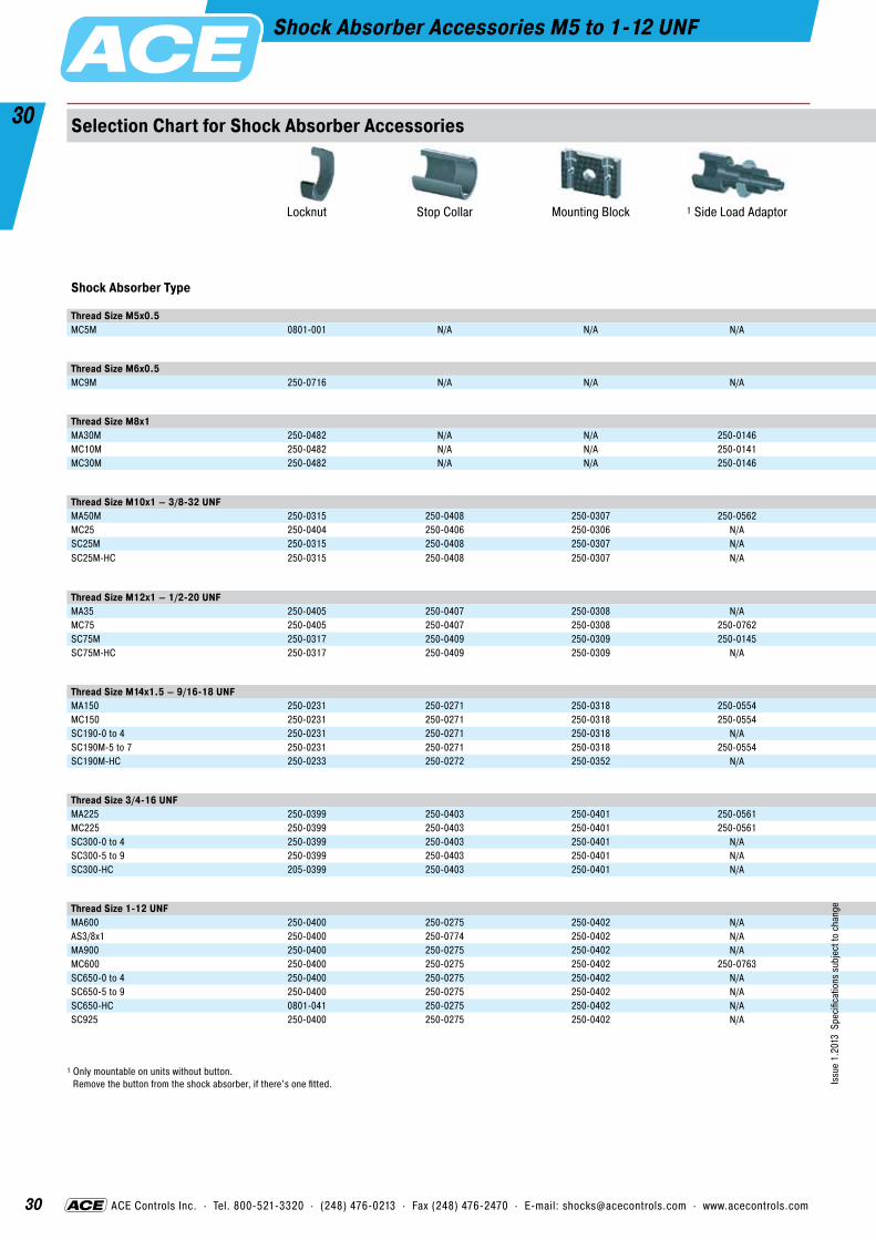
Shock Absorber Accessories M5 to 1-12 UNF
1 Only mountable on units without button. Remove the button from the shock absorber, if there’s one fitted.
Selection Chart for Shock Absorber Accessories
Locknut Stop Collar Mounting Block 1 Side Load Adaptor 1 Steel Shroud 2 PNP StopLight Assembly
(Switch Stop Collar AS see pages 32 & 33)
Steel Button Steel/Urethane Button Nylon Button
Shock Absorber Type Page
Thread Size M5x0.5 Thread Size M5x0.5MC5M 0801-001 N/A N/A N/A N/A N/A N/A N/A N/A 32
Thread Size M6x0.5 Thread Size M6x0.5MC9M 250-0716 N/A N/A N/A N/A N/A N/A N/A N/A 32
Thread Size M8x1 Thread Size M8x1MA30M 250-0482 N/A N/A 250-0146 250-0832 N/A N/A N/A N/A 32MC10M 250-0482 N/A N/A 250-0141 250-0833 N/A N/A N/A N/A 32MC30M 250-0482 N/A N/A 250-0146 250-0832 N/A N/A N/A N/A 32
Thread Size M10x1 – 3/8-32 UNF Thread Size M10x1 / 3/8-32 UNFMA50M 250-0315 250-0408 250-0307 250-0562 250-0834 AS10 250-0124 N/A N/A 32MC25 250-0404 250-0406 250-0306 N/A 250-0834 N/A 250-0124 250-0094 N/A 32SC25M 250-0315 250-0408 250-0307 N/A 250-0835 N/A 250-0175 N/A N/A 32SC25M-HC 250-0315 250-0408 250-0307 N/A 250-0835 N/A 250-0175 N/A N/A 32
Thread Size M12x1 – 1/2-20 UNF Thread Size M12x1 / 1/2-20 UNFMA35 250-0405 250-0407 250-0308 N/A 250-0836 N/A 250-0786 250-0094 N/A 33MC75 250-0405 250-0407 250-0308 250-0762 250-0836 N/A 250-0786 250-0094 N/A 33SC75M 250-0317 250-0409 250-0309 250-0145 250-0837 AS12 250-0174 N/A N/A 33SC75M-HC 250-0317 250-0409 250-0309 N/A 250-0837 AS12 250-0174 N/A N/A 33
Thread Size M14x1.5 – 9/16-18 UNF Thread Size M14x1.5 – 9/16-18 UNFMA150 250-0231 250-0271 250-0318 250-0554 250-0785 250-0387 250-0111 250-0095 250-0753 33MC150 250-0231 250-0271 250-0318 250-0554 250-0785 250-0387 250-0111 250-0095 250-0753 33SC190-0 to 4 250-0231 250-0271 250-0318 N/A 250-0733 250-0387 included 250-0096 N/A 33SC190M-5 to 7 250-0231 250-0271 250-0318 250-0554 250-0785 250-0387 250-0111 250-0095 N/A 33SC190M-HC 250-0233 250-0272 250-0352 N/A 250-0785 250-0387 250-0111 250-0095 N/A 33
Thread Size 3/4-16 UNF Thread Size 3/4-16 UNFMA225 250-0399 250-0403 250-0401 250-0561 250-0734 250-0391 included 250-0098 N/A 34MC225 250-0399 250-0403 250-0401 250-0561 250-0170 250-0391 250-0112 250-0097 250-0754 34SC300-0 to 4 250-0399 250-0403 250-0401 N/A 250-0734 250-0391 included 250-0098 N/A 34SC300-5 to 9 250-0399 250-0403 250-0401 N/A 250-0734 250-0391 included 250-0105 N/A 34SC300-HC 205-0399 250-0403 250-0401 N/A 250-0734 250-0391 included 250-0105 N/A 34
Thread Size 1-12 UNF Thread Size 1-12 UNFMA600 250-0400 250-0275 250-0402 N/A 250-0765 250-0395 included 250-0100 N/A 34AS3/8x1 250-0400 250-0774 250-0402 N/A N/A 250-0395 included 3 250-0767 N/A 34MA900 250-0400 250-0275 250-0402 N/A N/A 250-0395 included 250-0100 N/A 34MC600 250-0400 250-0275 250-0402 250-0763 250-0171 250-0395 250-0113 250-0099 250-0755 34SC650-0 to 4 250-0400 250-0275 250-0402 N/A 250-0765 250-0395 included 250-0100 N/A 34SC650-5 to 9 250-0400 250-0275 250-0402 N/A 250-0171 250-0395 included 250-0099 N/A 34SC650-HC 0801-041 250-0275 250-0402 N/A 250-0171 250-0395 included 250-0099 N/A 34SC925 250-0400 250-0275 250-0402 N/A N/A 250-0395 included 250-0100 N/A 34
Issu
e 1.
2013
Spe
cific
atio
ns s
ubje
ct to
cha
nge

31
31
ACE Controls Inc. · Tel. 800-521-3320 · (248) 476-0213 · Fax (248) 476-2470 · E-mail: [email protected] · www.acecontrols.com
Shock Absorber Accessories M5 to 1-12 UNF
1 Only mountable on units without button. Remove the button from the shock absorber, if there’s one fitted.
2 NPN assemblies also available on request. 3 Different style than the -BP button. This poly-pad snaps over the standard steel button.
Dimensions see pages 32 to 34.
Selection Chart for Shock Absorber Accessories
Locknut Stop Collar Mounting Block 1 Side Load Adaptor 1 Steel Shroud 2 PNP StopLight Assembly
(Switch Stop Collar AS see pages 32 & 33)
Steel Button Steel/Urethane Button Nylon Button
Shock Absorber Type Page
Thread Size M5x0.5 Thread Size M5x0.5MC5M 0801-001 N/A N/A N/A N/A N/A N/A N/A N/A 32
Thread Size M6x0.5 Thread Size M6x0.5MC9M 250-0716 N/A N/A N/A N/A N/A N/A N/A N/A 32
Thread Size M8x1 Thread Size M8x1MA30M 250-0482 N/A N/A 250-0146 250-0832 N/A N/A N/A N/A 32MC10M 250-0482 N/A N/A 250-0141 250-0833 N/A N/A N/A N/A 32MC30M 250-0482 N/A N/A 250-0146 250-0832 N/A N/A N/A N/A 32
Thread Size M10x1 – 3/8-32 UNF Thread Size M10x1 / 3/8-32 UNFMA50M 250-0315 250-0408 250-0307 250-0562 250-0834 AS10 250-0124 N/A N/A 32MC25 250-0404 250-0406 250-0306 N/A 250-0834 N/A 250-0124 250-0094 N/A 32SC25M 250-0315 250-0408 250-0307 N/A 250-0835 N/A 250-0175 N/A N/A 32SC25M-HC 250-0315 250-0408 250-0307 N/A 250-0835 N/A 250-0175 N/A N/A 32
Thread Size M12x1 – 1/2-20 UNF Thread Size M12x1 / 1/2-20 UNFMA35 250-0405 250-0407 250-0308 N/A 250-0836 N/A 250-0786 250-0094 N/A 33MC75 250-0405 250-0407 250-0308 250-0762 250-0836 N/A 250-0786 250-0094 N/A 33SC75M 250-0317 250-0409 250-0309 250-0145 250-0837 AS12 250-0174 N/A N/A 33SC75M-HC 250-0317 250-0409 250-0309 N/A 250-0837 AS12 250-0174 N/A N/A 33
Thread Size M14x1.5 – 9/16-18 UNF Thread Size M14x1.5 – 9/16-18 UNFMA150 250-0231 250-0271 250-0318 250-0554 250-0785 250-0387 250-0111 250-0095 250-0753 33MC150 250-0231 250-0271 250-0318 250-0554 250-0785 250-0387 250-0111 250-0095 250-0753 33SC190-0 to 4 250-0231 250-0271 250-0318 N/A 250-0733 250-0387 included 250-0096 N/A 33SC190M-5 to 7 250-0231 250-0271 250-0318 250-0554 250-0785 250-0387 250-0111 250-0095 N/A 33SC190M-HC 250-0233 250-0272 250-0352 N/A 250-0785 250-0387 250-0111 250-0095 N/A 33
Thread Size 3/4-16 UNF Thread Size 3/4-16 UNFMA225 250-0399 250-0403 250-0401 250-0561 250-0734 250-0391 included 250-0098 N/A 34MC225 250-0399 250-0403 250-0401 250-0561 250-0170 250-0391 250-0112 250-0097 250-0754 34SC300-0 to 4 250-0399 250-0403 250-0401 N/A 250-0734 250-0391 included 250-0098 N/A 34SC300-5 to 9 250-0399 250-0403 250-0401 N/A 250-0734 250-0391 included 250-0105 N/A 34SC300-HC 205-0399 250-0403 250-0401 N/A 250-0734 250-0391 included 250-0105 N/A 34
Thread Size 1-12 UNF Thread Size 1-12 UNFMA600 250-0400 250-0275 250-0402 N/A 250-0765 250-0395 included 250-0100 N/A 34AS3/8x1 250-0400 250-0774 250-0402 N/A N/A 250-0395 included 3 250-0767 N/A 34MA900 250-0400 250-0275 250-0402 N/A N/A 250-0395 included 250-0100 N/A 34MC600 250-0400 250-0275 250-0402 250-0763 250-0171 250-0395 250-0113 250-0099 250-0755 34SC650-0 to 4 250-0400 250-0275 250-0402 N/A 250-0765 250-0395 included 250-0100 N/A 34SC650-5 to 9 250-0400 250-0275 250-0402 N/A 250-0171 250-0395 included 250-0099 N/A 34SC650-HC 0801-041 250-0275 250-0402 N/A 250-0171 250-0395 included 250-0099 N/A 34SC925 250-0400 250-0275 250-0402 N/A N/A 250-0395 included 250-0100 N/A 34
Issu
e 1.
2013
Spe
cific
atio
ns s
ubje
ct to
cha
nge

32
32
Issu
e 7.
2014
Spe
cific
atio
ns s
ubje
ct to
cha
nge
ACE Controls Inc. · Tel. 800-521-3320 · (248) 476-0213 · Fax (248) 476-2470 · E-mail: [email protected] · www.acecontrols.com
Shock Absorber Accessories M5 to M10 – 3/8-32 UNFSelection Chart See Pages 32 to 33
M5x0.5 M6x0.50801-001
Locknut
M5x0.5
.16AF.32
250-0716
Locknut
M6x0.5
.10AF.31
M8x1250-0482
Locknut
M8x1
.12AF.39
250-0141
Side Load Adaptor
.47
.39.39
AF .35AF .39
.20
.43 M8x1
.16Ø
Ø
250-0832
Steel Shroud
.47 .10
.08.50.69
Ø Ø
M10x1 – 3/8-32 UNF250-0404 (standard)
Locknut
3/8-32 UNF
.10AF.50
250-0406 (standard)
Stop Collar
3/8-32 UNF.56
.81 .39.39Ø
Ø
250-0306 (standard)
Mounting Block1.5
1.0
3/8-32 UNF .18 Dia. Thru .31C’Bore x .20 Deep#8-32 Soc. Hd. Screw
1.0
.24
#8-32 Soc. Hd. ScrewThru 2 Holes
.50
250-0562
Side Load Adaptor
.59
.43.47
AF .43AF .47
.26
.51 M10x1
.24Ø
Ø
250-0834
Steel Shroud
.55 .13
.12.55
.87
Ø Ø
AS10
Switch Stop Collar inc. Proximity Switch
M10x1.67
.87 .47
.59Ø
250-0124
Steel Button
.35
.20.31
.12Ø
Ø
Mounting, installation... see pages 37 to 39.
250-0307 (metric)
Mounting Block
1.50
.98
.20
M10x1
.18.98
Ø
.24
250-0315 (metric)
Locknut
M10x1
.16AF.47
250-0408 (metric)
Stop Collar
M10x1.49
.79 .39.39Ø
Ø
250-0833
Steel Shroud
.47 .08
.08.39
.59
Ø Ø
250-0835
Steel Shroud
.55 .13
.16.59
.87
Ø Ø
250-0146
Side Load Adaptor
.59
.59.39
AF .35AF .39
.31
.43 M8x1
.16Ø
Ø
250-0094
Steel/Urethane Button
.41
.20.37
.13ØØ
250-0175
Steel Button
.35
.12.20
.12Ø
Ø
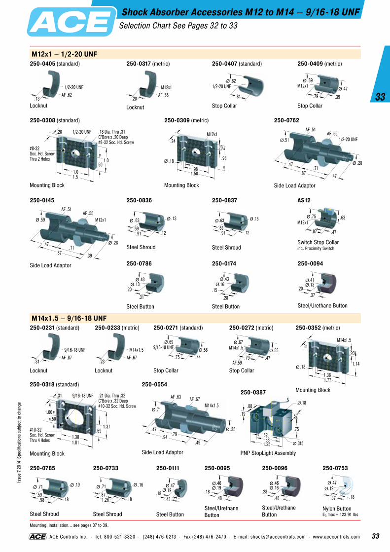
33
33
Issu
e 7.
2014
Spe
cific
atio
ns s
ubje
ct to
cha
nge
ACE Controls Inc. · Tel. 800-521-3320 · (248) 476-0213 · Fax (248) 476-2470 · E-mail: [email protected] · www.acecontrols.com
Shock Absorber Accessories M12 to M14 – 9/16-18 UNFSelection Chart See Pages 32 to 33
M12x1 – 1/2-20 UNF
M14x1.5 – 9/16-18 UNF250-0231 (standard)
Locknut
9/16-18 UNF
.31AF .87
250-0272 (metric)
Stop Collar
M14x1.5.67
.79 .47.55Ø
Ø
AF.59
250-0318 (standard)
Mounting Block
1.81
1.37
9/16-18 UNF .21 Dia. Thru .32C’Bore x .32 Deep#10-32 Soc. Hd. Screw
1.38
.50
.31
.69
1.00
#10-32 Soc. Hd. ScrewThru 4 Holes
250-0785
Steel Shroud
.71 .19
.18.59
.98
Ø Ø
250-0733
Steel Shroud
.71 .16
.18.871.26
Ø Ø
250-0111
Steel Button
.47.18
.43
.19Ø
Ø
250-0095
Steel/Urethane Button
.46
.18.48
.19ØØ
250-0753
Nylon Button E3 max = 123.91 lbs
.47
.18.37
.19Ø
Ø
Mounting, installation... see pages 37 to 39.
250-0317 (metric)
Locknut
M12x1
.20AF .55
250-0407 (standard)
Stop Collar
1/2-20 UNF.62
.81
Ø
250-0308 (standard)
Mounting Block1.5
1.0
1/2-20 UNF .18 Dia. Thru .31C’Bore x .20 Deep#8-32 Soc. Hd. Screw
1.0
.28
#8-32 Soc. Hd. ScrewThru 2 Holes
.50
250-0836
Steel Shroud
.63 .13
.12.59
.91
Ø Ø
AS12
Switch Stop Collar inc. Proximity Switch
M12x1.75
.87 .47
.63Ø
250-0786
Steel Button
.43
.20.31
.13Ø
Ø
250-0174
Steel Button
.43
.15.28
.16Ø
Ø
250-0145
Side Load Adaptor
.87
.47.71
AF .51AF .55
.39
.59 M12x1
.28Ø
Ø
250-0837
Steel Shroud
.63 .16
.12.63
.91
Ø Ø
250-0309 (metric)
Mounting Block
1.50
.98
.20
M12x1
.18.98
Ø
.24
250-0352 (metric)
Mounting Block
1.77
1.14
.20
M14x1.5
.18
1.38
Ø
.31
250-0405 (standard)
Locknut
1/2-20 UNF
.13AF .62
250-0233 (metric)
Locknut
M14x1.5
.23AF .67
250-0409 (metric)
Stop Collar
M12x1.59
.79 .39
.47Ø
Ø
250-0271 (standard)
Stop Collar
9/16-18 UNF.69
.75 .44.58Ø
Ø
250-0094
Steel/Urethane Button
.41
.20.37
.13ØØ
250-0096
Steel/Urethane Button
.46
.28.48
.16ØØ
250-0762
Side Load Adaptor
.87
.47.71
AF .51AF .55
.47
.51 1/2-20 UNF
.28Ø
Ø
250-0554
Side Load Adaptor
M14x1.5.71
.94.47 .35
.79
AF .63 AF .67
.49
Ø
Ø
250-0387
PNP StopLight Assembly1.25
.75.52
.88
.57
�.315.88
.19
�.18

34
34
Issu
e 7.
2014
Spe
cific
atio
ns s
ubje
ct to
cha
nge
ACE Controls Inc. · Tel. 800-521-3320 · (248) 476-0213 · Fax (248) 476-2470 · E-mail: [email protected] · www.acecontrols.com
Shock Absorber Accessories 3/4-16 UNF to 1-12 UNFSelection Chart See Pages 32 to 33
3/4-16 UNF250-0399
Locknut
3/4-16 UNF
.25AF 1.00
250-0403
Stop Collar
3/4-16 UNF1.00
1.25 .44.77Ø
Ø
2580-0401
Mounting Block
2.00
1.50
3/4-16 UNF .22 Dia. Thru .33C’Bore x .45 Deep#10-32 Soc. Hd. Screw
1.50
.56
.31
.75
1.12
#10-32 Soc. Hd. ScrewThru 4 Holes
250-0561
Side Load Adaptor
3/4-16 UNF.95
.95
.55 .47.79
AF .88 AF 1.00
.49
Ø
Ø
250-0170
Steel Shroud
.94 .25
.16.59
.94
Ø Ø
250-0734
Steel Shroud
.94 .19
.201.02
1.46
Ø Ø
250-0391
PNP StopLight Assembly
1.56
.94.62
.94
.63
�.221.1
.24
�.22
250-0097
Steel/Urethane Button
.66
.18.52
.25ØØ
250-0754
Nylon Button E3 max = 292.07 lbs
.66
.19.35
.25Ø
Ø
1-12 UNF250-0400
Locknut
1-12 UNF
.25AF 1.25
250-0275
Stop Collar
1-12 UNF1.25
1.75 .59
1.02Ø
Ø
250-0763
Side Load Adaptor
1-12 UNF1.18
1.73
.32 .631.50
AF 1.05 AF 1.25
.99
Ø
Ø
250-0171
Steel Shroud
1.14 .31
.181.261.69
Ø Ø
250-0765
Steel Shroud
1.14 .25
.181.261.69
Ø Ø
250-0113
Steel Button
.91
.25.39
.31Ø
Ø
250-0099
Steel/Urethane Button
.89
.22.57
.31ØØ
250-0755
Nylon Button E3 max = 601.85 lbs
.90
.20.42
.31ØØ
Mounting, installation... see pages 37 to 39.
250-0402
Mounting Block
2.00
1.50
1-12 UNF .22 Dia. Thru .33C’Bore x .45 Deep#10-32 Soc. Hd. Screw
1.50
.56
.31
.75
1.12
#10-32 Soc. Hd. ScrewThru 4 Holes
0801-041
Locknut
1-12 UNF
.57AF 1.50
250-0774
Stop Collar
1-12 UNF1.25
2.19 1.17
.91Ø
Ø
250-0098
Steel/Urethane Button
.66
.27.52
.19ØØ
250-0105
Steel/Urethane Button
.66
.27.52
.19ØØ
250-0100
Steel/Urethane Button
.89
.26.57
.25ØØ
250-0767
Poly Button
.87
.24.48
.77Ø
Ø
250-0112
Steel Button
.66
.17.43
.25Ø
Ø
250-0395
PNP StopLight Assembly
1.75
1.18.62
1.00
.63
�.221.26
.28
�.22

35
35
Issu
e 7.
2014
Spe
cific
atio
ns s
ubje
ct to
cha
nge
ACE Controls Inc. · Tel. 800-521-3320 · (248) 476-0213 · Fax (248) 476-2470 · E-mail: [email protected] · www.acecontrols.com
Mounting and Installation HintsUp to 1-12 UNF
Stop Collar All ACE miniature shock absorbers have an integral positive stop. An optional stop collar can be added if desired to give fine adjustment of final stopping position.
Lock Nut
Stroke
Stop CollarPositive Stop
Mounting Block This versatile block can be mounted to a horizontal or vertical surface. The shock is screwed into the center threaded hole and secured with a locknut. One locknut is included with each shock.
Stroke
Steel Shroud Grinding beads, sand, welding splatter, paints and adhesives etc. can adhere to the piston rod. They then damage the rod seals and the shock absorber quickly fails. In many cases the installation of the optional steel shroud can provide worthwhile protection and increase lifetime.Note! When installing don’t forget to allow operating space for the shroud to move as the shock absorber is cycled. For part number MA, MC, SC please order with “-880” suffix. Part numbers MA150, MC150 to MC600 and SC25M to SC190M5-7 are supplied without a button.
Steel Shroud
Stroke
Stroke
Shock Absorber

36
36
Issu
e 7.
2014
Spe
cific
atio
ns s
ubje
ct to
cha
nge
ACE Controls Inc. · Tel. 800-521-3320 · (248) 476-0213 · Fax (248) 476-2470 · E-mail: [email protected] · www.acecontrols.com
Side Load Adaptor With side load impact angles of more than 3° the operation lifetime of the shock absorber reduces rapidly due to increased wear of the rod bearings. The optional side load adaptor provides long lasting solution. Secure the side load adaptor with Loctite or lock nut on the shock absorber. Material: Threaded body and plunger: Hardened high tensile steel. Hardened 610 HV1. Note: Material that impacts the side load adaptor should be hardened to a similar value. We recommend that you install the shock absorber/side load adaptor using the thread on the side load adaptor.
Problem: Rotating impact motion causes high side load forces on the piston rod. This increases bearing wear and possibly results in rod breakage or bending. Solution: Install side load adaptor.
Maximum angle: 250-0141, 250-0145, 250-0146, 250-0562 250-0762 = 12.5°250-0554,250-0561, 250-0763 = 25° Note: By repositioning the center of the stroke of the side load plunger to be at 90 degrees to the piston rod, the side load angle can be halved. The use of an external positive stop due to high forces encountered is required.
Shock Absorber Threaded Body Positive Stop Plunger
Rs
Stroke s
α
Formulae:
α = tan-1 Rs min =
Example:
s = .98 α max = 25° (adapter 250-0763)
Rs = 3.94
α = tan-1 Rs min =
α = 14° Rs min = 2.1 in
α = side load angle (°) Rs = mounting radius (in)α max = max. angle of impact (°) Rs min = min. possibles = absorber stroke (in) mounting radius (in)
s2 · tan α max
.98tan (25°)
( )
( ).983.94
s2 · Rs
Mounting and Installation HintsUp to 1-12 UNF
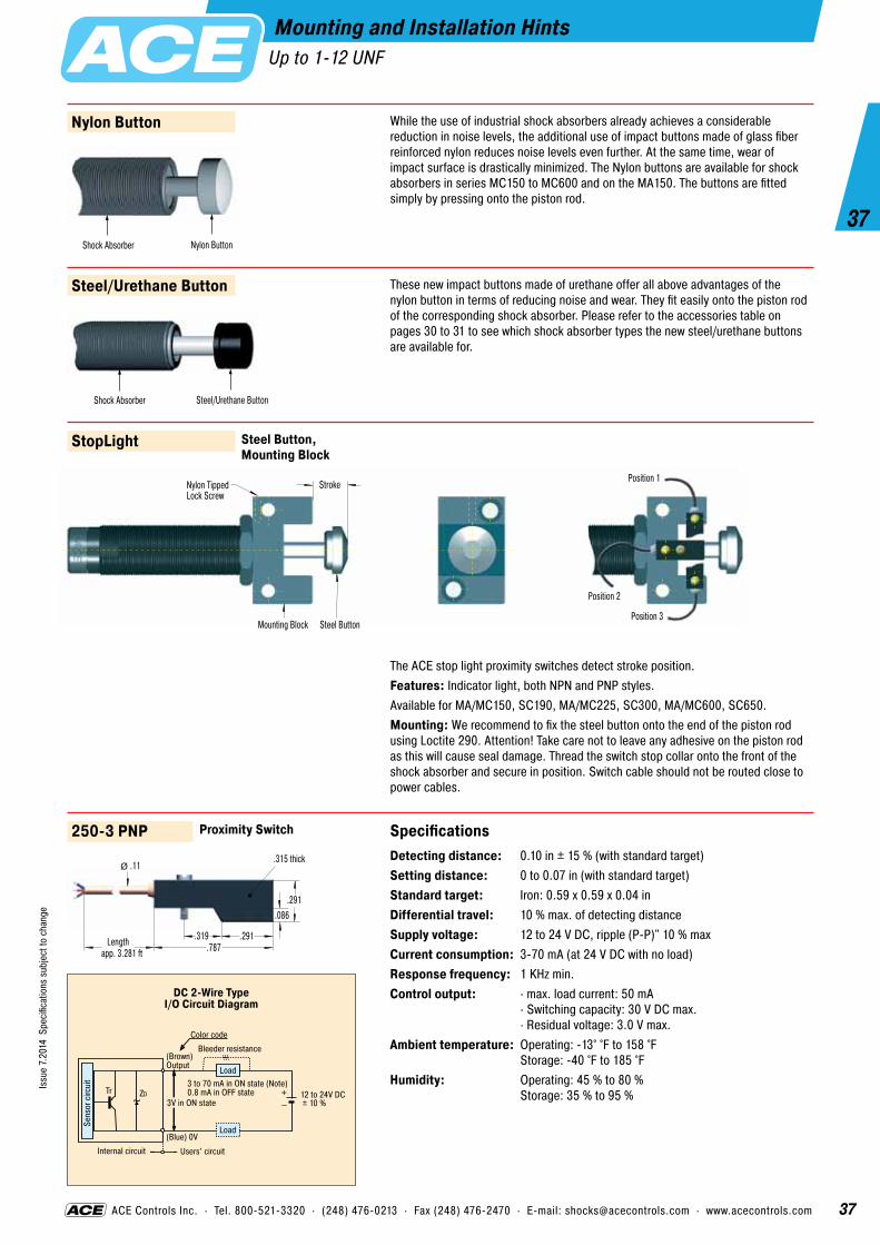
37
37
Issu
e 7.
2014
Spe
cific
atio
ns s
ubje
ct to
cha
nge
ACE Controls Inc. · Tel. 800-521-3320 · (248) 476-0213 · Fax (248) 476-2470 · E-mail: [email protected] · www.acecontrols.com
Mounting and Installation HintsUp to 1-12 UNF
StopLight
The ACE stop light proximity switches detect stroke position.Features: Indicator light, both NPN and PNP styles.Available for MA/MC150, SC190, MA/MC225, SC300, MA/MC600, SC650.Mounting: We recommend to fix the steel button onto the end of the piston rod using Loctite 290. Attention! Take care not to leave any adhesive on the piston rod as this will cause seal damage. Thread the switch stop collar onto the front of the shock absorber and secure in position. Switch cable should not be routed close to power cables.
Steel Button, Mounting Block
Steel/Urethane Button These new impact buttons made of urethane offer all above advantages of the nylon button in terms of reducing noise and wear. They fit easily onto the piston rod of the corresponding shock absorber. Please refer to the accessories table on pages 30 to 31 to see which shock absorber types the new steel/urethane buttons are available for.
Shock Absorber Steel/Urethane Button
Nylon Button While the use of industrial shock absorbers already achieves a considerable reduction in noise levels, the additional use of impact buttons made of glass fiber reinforced nylon reduces noise levels even further. At the same time, wear of impact surface is drastically minimized. The Nylon buttons are available for shock absorbers in series MC150 to MC600 and on the MA150. The buttons are fitted simply by pressing onto the piston rod.
Shock Absorber Nylon Button
250-3 PNP Specifications Detecting distance: 0.10 in ± 15 % (with standard target) Setting distance: 0 to 0.07 in (with standard target) Standard target: Iron: 0.59 x 0.59 x 0.04 in Differential travel: 10 % max. of detecting distance Supply voltage: 12 to 24 V DC, ripple (P-P)" 10 % max Current consumption: 3-70 mA (at 24 V DC with no load) Response frequency: 1 KHz min. Control output: · max. load current: 50 mA
· Switching capacity: 30 V DC max. · Residual voltage: 3.0 V max.
Ambient temperature: Operating: -13° °F to 158 °F Storage: -40 °F to 185 °F
Humidity: Operating: 45 % to 80 % Storage: 35 % to 95 %
Proximity Switch
.315 thick
.787
.291
.291.319
.086
.11
app. 3.281 ftLength
Ø
Nylon TippedLock Screw
Stroke
Position 2
Position 3
Position 1
Steel ButtonMounting Block
Color code
Bleeder resistance(Brown)Output
Tr ZD
(Blue) 0VLoad
Load3 to 70 mA in ON state (Note)0.8 mA in OFF state
3V in ON state
Internal circuit Users’ circuit
12 to 24V DC± 10 %
Sens
or c
ircui
t
+–
DC 2-Wire TypeI/O Circuit Diagram

38
38
Issu
e 7.
2014
Spe
cific
atio
ns s
ubje
ct to
cha
nge
Industrial Shock Absorbers MC33 to MC64 Self-Compensating
Fully Threaded Outer Body
Integrated Positive Stop
Main Bearing
Hardened Piston RingIncreased Piston Area
Hardened One-PiecePressure Chamber
Membrane Accumulator
Rod Seals
Rod Button
Heavy Duty One-PieceSteel Outer Body
This range of self-compensating shock absorb- ers is part of the innovative MAGNUM series from ACE. You profit from the enhanced product life in the most difficult operating environments provided by the latest seal technology, hardened main bearing and also the integrated positive stop. You achieve 50% more energy absorp-tion capacity and a much wider range of effec- tive weight capability (between 20 lbs and 140,700 lbs!). This offers you the capability of mounting shock absorbers with the highest en- ergy capacity ratings for their size in the industry and allows full exploitation of your machinery potential. You can access new possibilities in machine design and construction since this range offers such features as a fully threaded outer body and a new clamping flange system.
Impact velocity range: 0.5 to 16.5 ft/sec, on request up to 65.6 ft/sec.Operating fluid: Automatic Transmission Fluid (ATF)Material: Shock absorber body: Nitride hardened steel. Accessories: Steel with zinc-iron black finish or nitride hardened. Piston rod: Steel hardened and chrome plated. Rod end button: Hardened steel with black oxide finish. Return spring: Zinc plated or plastic-coated. For optimum heat dissipation do not paint shock absorber.Capacity rating: For emergency use only applications it is sometimes possible to exceed the published max. capacity ratings. Please consult ACE for further details. If your appli cation exceeds the tabulated E4 figures (max. energy per hour in-lbs/hr) consider additional cooling. Ask ACE for further details.Mounting: In any positionOperating temperature range: 10 °F to 158 °F. Higher and lower temperatures see pages 46 to 47.On request: Plated finishes. Weartec finish (seawater resistant), special oils. Mounting inside air cylinders and other special options are available on request.Noise reduction: 3 to 7 dB when using the impact buttons with urethane insert.

39
39
Issu
e 7.
2014
Spe
cific
atio
ns s
ubje
ct to
cha
nge
Industrial Shock Aborbers MA and ML33 to 64Adjustable
Adjustment: Turning the front stop collar or rear adjuster towards 0 makes the unit harder. Turning towards 9 makes the unit softer.Impact velocity range: Type ML: 0.06 up to 1.5 ft/sec, type MA: 0.5 up to 16.5 ft/sec, (up to 65.6 ft/sec on request).Operating fluid: Automatic Transmission Fluid (ATF)Material: Shock absorber body: Nitride hardened steel. Accessories: Steel with zinc-iron black finish or nitride hardened. Piston rod: Steel hardened and chrome plated. Rod end button: Hardened steel with black oxide finish. Return spring: Zinc plated or plastic-coated. For optimum heat dissipation do not paint shock absorber.Capacity rating: For emergency use only applications it is sometimes possible to exceed the published max. capacity ratings. Please consult ACE for further details. If your application exceeds the tabulated E4 fig- ures (max. energy per hour in-lbs/hr) consider additional cooling. Ask ACE for further details.Mounting: In any positionOperating temperature range: 10 °F to 158 °F. Higher and lower temperatures see pages 46 to 47.On request: Plated finishes. Weartec finish (seawater resistant), special oils. Mounting inside air cylinders and other special options are available on request.Noise reduction: 3 to 7 dB when using the impact buttons with urethane insert.
Fully Threaded Outer Body
Integrated Positive Stop
Main Bearing
Hardened Piston RingIncreased Piston Area
Hardened One-PiecePressure Chamber
Front Adjuster
Membrane Accumulator
Rear Adjuster
Heavy Duty One-Piese Steel Outer Body
Locking Screw (MA/ML64 only)
Rod Seals
Rod Button
This adjustable shock absorber from ACE is unique. The innovative MAGNUM series models provide the next generation of deceleration technology to meet the needs of the future. The latest seal technology, a hardened main bearing and the integrated positive stop provide a significant increase in operating lifetime. Other innovations such as the front and rear adjuster, clamping flanges and the fully threaded outer body provide many new options in installation and mounting. Exploit the advantages of this series in your applications with its 50% in- creased energy capacity and a much wider effective weight range. The effective weight range extends from 20 lbs up to 175,000 lbs. The MA range models cover the majority of standard applications, whilst the ML range is specially designed for low velocity/high effective weight applications from 660 lbs up to 1,102,310 lbs effective weight.

40
40
Issu
e 7.
2014
Spe
cific
atio
ns s
ubje
ct to
cha
nge
ACE Controls Inc. · Tel. 800-521-3320 · (248) 476-0213 · Fax (248) 476-2470 · E-mail: [email protected] · www.acecontrols.com
.50
.761.50 (1.56)
.48
L6 max
L5 max
.51
.25
.2510.2510
.75
.50
MA, MC & ML-C ModelsInclude Spring
.32
Dimensions for MC, MA, ML3350 in ( )
L4
Industrial Shock Aborbers MC/MA/ML33Self-Compensating and Adjustable
Adjuster (MA and ML only)
� 1.00
A max
.75
.375.99� 1.15
1-1/4-12 UNF1/8 NPT MALE
B maxL2
250-0225
DimensionsType
1 Stroke inches
A max
B max
L1 min
L4
L2
L3
L5 max
L6 max
MC, MA, ML3325 0.98 5.44 0.91 3.75 2.64 3.25 1.94 1.36 6.58MC, MA, ML3350 1.97 7.44 1.91 4.75 3.64 4.25 2.94 2.36 8.58
1 Nominal stroke length (without integral stop collar fitted).
Capacity Chart MC33Max. Energy Capacity 1 Effective Weight We
Soft HardType Self-Com-pensating
2 E3 in-lbs/Cycle
E4 Self-Con-
tained in-lbs/h
E4 with Air/Oil Tank
in-lbs/h
E4 with Oil Recir-culation in-lbs/h
-0 min. max.
lbs
-1 min. max.
lbs
-2 min. max.
lbs
-3 min. max.
lbs
-4 min. max.
lbs
Min. Return Force lbs
Max. Return Force lbs
Rod Reset Time sec
Max. Side Load
Angle °
Weight lbs
MC3325 1,350 670,000 1,100,000 1,500,000 6.61-24.25 20- 80 68-272 230- 920 780-3,120 10.3 19.8 0.03 4 1.00MC3350 2,700 760,000 1,200,000 1,600,000 11.00-48.50 40-160 136-544 460-1,840 1,560-6,240 9.9 30.3 0.06 3 1.20
Capacity Chart MA/ML33Max. Energy Capacity 1 Effective Weight We
Type Adjustable
2 E3 in-lbs/Cycle
E4 Self-Con-
tained in-lbs/h
E4 with Air/Oil Tank
in-lbs/h
E4 with Oil Recircula-
tion in-lbs/h
min. max. lbs
Min. Return Force lbs
Max. Return Force lbs
Rod Reset Time sec
Max. Side Load
Angle °
Weight lbs
MA3325 1,500 670,000 1,100,000 1,500,000 20 - 3,800 10.3 19.8 0.03 4 1.0ML3325 1,500 670,000 1,100,000 1,500,000 661 - 110,231 10.3 19.8 0.03 4 1.0MA3350 3,000 760,000 1,200,000 1,600,000 28 - 5,400 9.9 30.3 0.06 3 1.2ML3350 3,000 760,000 1,200,000 1,600,000 1,102 - 176,370 9.9 30.3 0.06 3 1.2
1 The effective weight range limits can be raised or lowered to special order. 2 For emergency use only applications it is sometimes possible to exceed the above ratings. Please consult ACE for further details. Specifications relate to the effective stroke length (B max).
Clevis Mount Assembly
.25
.235 .235
.25L3L1
2.00
1/8 NPT MALE
.50
2.37
2.75
.87
250-0015
Side-Foot Mount Assembly
M36x1.5 also available to order

41
41
Issu
e 7.
2014
Spe
cific
atio
ns s
ubje
ct to
cha
nge
ACE Controls Inc. · Tel. 800-521-3320 · (248) 476-0213 · Fax (248) 476-2470 · E-mail: [email protected] · www.acecontrols.com
Ordering Example MC3325-1Self-CompensatingThread Size 1-1/4-12 UNF (M33)Stroke 0.98" (25 mm)Effective Weight Range Version
Model Type Prefix
Standard ModelsSelf-Contained with Return SpringMC Self-Compensating MA Adjustable ML Adjustable, for lower impact velocity
Special ModelsAir/Oil Return without Return Spring MCA, MAA, MLAAir/Oil Return with Return Spring MCS, MAS, MLSSelf-Contained without Return Spring MCN, MAN, MLN
Industrial Shock Absorbers MC/MA/ML33 Shock Absorber Accessories
1-1/4-12 UNF
250-0730
Steel ShroudStroke
.59
1.38
1.46.98
1 A max 5.83
Ø
Ø
250-0130
Steel Shroud 1 Total installation length of the shock
absorber inc. steel shroud
Stroke
.59
1.42
2.421.97
1 A max 7.80
Ø
Ø
250-0091
Poly ButtonOptional button with elastomer insert for noise suppression. Option supplied ready mounted onto the shock absorber.
1.15
.52A max
see shock absorber dims.
Ø
250-0038
Locking Ring
.25
1.50Ø
250-0016
Rectangular Flange
1.622.00
1.121.50
1-1/4-12 UNF
.22
250-0070
Flanged Stop Collar
2.50
2.00
1.50
.352.00
.88
.251-1/4-12 UNF
250-0426
Stop Bars
1.50
1.28
1.12
.19
.38
10-32 UNF

42
42
Issu
e 7.
2014
Spe
cific
atio
ns s
ubje
ct to
cha
nge
ACE Controls Inc. · Tel. 800-521-3320 · (248) 476-0213 · Fax (248) 476-2470 · E-mail: [email protected] · www.acecontrols.com
Industrial Shock Absorbers MC/MA/ML45Self-Compensating and Adjustable
DimensionsType
1 Stroke inches
A max
B max
L1 min
L4
L2
L3
L5 max
L6 max
MC, MA, ML4525 0.98 5.69 0.91 3.35 2.57 3.72 2.09 1.51 7.85MC, MA, ML4550 1.97 7.69 1.91 4.35 3.57 4.72 3.09 2.51 9.85MC, MA4575 2.95 9.69 2.91 5.35 4.57 5.72 4.09 3.51 11.85
1 Nominal stroke length (without integral stop collar fitted).
Capacity Chart MC45Max. Energy Capacity 1 Effective Weight We
Soft HardTypeSelf-Com-pensating
2 E3 in-lbs/Cycle
E4 Self-Con-
tained in-lbs/h
E4 with Air/Oil Tank
in-lbs/h
E4 with Oil Recir-culation in-lbs/h
-0 min. max.
lbs
-1 min. max.
lbs
-2 min. max.
lbs
-3 min. max.
lbs
-4 min. max.
lbs
Min. Return Force lbs
Max. Return Force lbs
Rod Reset Time sec
Max. Side Load
Angle °
Weight lbs
MC4525 3,000 950,000 1,400,000 1,700,000 15.4- 59.2 50-200 170- 680 575-2,300 1,950- 7,800 15.1 22.8 0.03 4 2.5MC4550 6,000 1,000,000 1,700,000 2,200,000 28.6-119.0 100-400 340-1,360 1,150-4,600 3,900-15,600 15.1 32.2 0.08 3 3.0MC4575 9,000 1,300,000 2,000,000 2,500,000 44.0-176.4 150-600 510-2,040 1,370-6,920 5,850-23,400 11.7 40.3 0.11 2 3.5
Capacity Chart MA/ML45Max. Energy Capacity 1 Effective Weight We
Type Adjust-able
2 E3 in-lbs/Cycle
E4 Self-Con-
tained in-lbs/h
E4 with Air/Oil Tank
in-lbs/h
E4 with Oil Recir- culation in-lbs/h
min. max. lbs
Min. Return Force lbs
Max. Return Force lbs
Rod Reset Time sec
Max. Side Load
Angle °
Weight lbs
MA4525 3,450 950,000 1,400,000 1,700,000 95 - 22,000 15.1 22.8 0.03 4 2.5ML4525 6,900 950,000 1,400,000 1,700,000 6,614 - 242,508 15.1 32.2 0.03 4 2.5MA4550 6,900 1,000,000 1,700,000 2,200,000 150 - 32,000 15.1 32.2 0.08 3 3.0ML4550 6,900 1,000,000 1,700,000 2,200,000 11,023 - 396,832 15.1 32.2 0.08 3 3.0MA4575 10,350 1,300,000 2,000,000 2,500,000 155 - 33,000 11.7 40.3 0.11 2 3.5
1 The effective weight range limits can be raised or lowered to special order. 2 For emergency use only applications it is sometimes possible to exceed the above ratings. Please consult ACE for further details. Specifications relate to the effective stroke length (B max).
.75
1.002.25
1.06
L6 maxL4
L5 max
.69
.50
.3755
.5005
1.00
1.00
.50
.505
Adjuster (MA and ML only)
� 1.38
A max
.87
.501.36� 1.65
1-3/4-12 UNF1/8 NPT B maxL2
.50.35 .35
.37L3L1
2.25
1/8 NPT
.56
3.00
3.75
1.16
250-0324
250-0025
Side-Foot Mount Assembly
Clevis Mount Assembly

43
43
Issu
e 7.
2014
Spe
cific
atio
ns s
ubje
ct to
cha
nge
ACE Controls Inc. · Tel. 800-521-3320 · (248) 476-0213 · Fax (248) 476-2470 · E-mail: [email protected] · www.acecontrols.com
Ordering Example ML4525AdjustableThread Size 1-3/4-12 (M45)Stroke 0.98" (25 mm)
Model Type Prefix
Standard ModelsSelf-Contained with Return SpringMC Self-Compensating MA Adjustable ML Adjustable, for lower impact velocity
Special ModelsAir/Oil Return without Return Spring MCA, MAA, MLAAir/Oil Return with Return Spring MCS, MAS, MLSSelf-Contained without Return Spring MCN, MAN, MLN
Industrial Shock Absorbers MC/MA/ML45 Shock Absorber Accessories
1-3/4-12 UNF
250-0092
Poly ButtonOptional button with elastomer insert for noise suppression. Option supplied ready mounted onto the shock absorber.
1.65
.76A max
see shock absorber dims.
Ø
250-0731
Steel ShroudStroke
.79
1.89
1.46.98
1 A max 6.06
Ø
Ø
250-0778
Steel Shroud 1 Total installation length of the shock
absorber inc. steel shroud
Stroke
.79
1.89
2.461.97
1 A max 8.05
Ø
Ø
250-0041
Locking Ring
.37
2.25Ø
250-0024
Rectangular Flange
2.383.00
1.622.25
1-3/4-12 UNF
.34250-0023
Square Flange
1.622.25
.34
.50
1-3/4-12 UNF
250-0072
Flanged Stop Collar
3.25
2.75
2.25
.351.85
.88
.251-3/4-12 UNF
250-0428
Stop Bars
2.25
1.03
1.62
.31
.63
5/16-24 UNF

44
44
Issu
e 7.
2014
Spe
cific
atio
ns s
ubje
ct to
cha
nge
ACE Controls Inc. · Tel. 800-521-3320 · (248) 476-0213 · Fax (248) 476-2470 · E-mail: [email protected] · www.acecontrols.com
Industrial Shock Absorbers MC/MA/ML64Self-Compensating and Adjustable
DimensionsType
1 Stroke inches
A max
B max
L1 min
L4
L2
L3
L5 max
L6 max
ML6425 0.98 6.85 0.91 4.00 3.75 4.5 2.54 2.31 10.12MC, MA, ML6450 1.97 8.85 1.91 5.00 4.75 5.5 3.54 3.31 12.12MC, MA64100 3.94 12.85 3.91 7.00 6.75 7.5 5.54 5.31 16.12MC, MA64150 5.91 17.73 5.91 9.00 9.50 9.5 8.42 8.06 20.87
1 Nominal stroke length (without integral stop collar fitted). Dimensions of the models MCA/MAA64150 available on request.
Capacity Chart MC64Max. Energy Capacity 1 Effective Weight We
Soft HardType Self-Com-pensating
2 E3 in-lbs/Cycle
E4 Self-Con-
tained in-lbs/h
E4 with Air/Oil Tank
in-lbs/h
E4 with Oil Recir-culation in-lbs/h
-0 min. max.
lbs
-1 min. max.
lbs
-2 min. max.
lbs
-3 min. max.
lbs
-4 min. max.
lbs
Min. Return Force lbs
Max. Return Force lbs
Rod Reset Time sec
Max. Side Load
Angle °
Weight lbs
MC6450 15,000 1,300,000 2,600,000 3,400,000 308-1,190 300-1,200 1,020- 4,080 3,460-13,480 11,700- 46,800 20.1 34.9 0.12 4 6.4MC64100 30,000 1,700,000 3,400,000 4,400,000 154- 617 600-2,400 2,040- 8,160 6,920-27,680 23,400- 93,600 23.5 61.0 0.34 3 8.15MC64150 45,000 2,200,000 4,400,000 5,700,000 220-1,014 900-3,600 3,060-12,240 10,380-41,520 35,100-140,400 16.9 82.2 0.48 2 11.25
Capacity Chart MA/ML64Max. Energy Capacity 1 Effective Weight We
Type Adjustable
2 E3 in-lbs/Cycle
E4 Self-Con-
tained in-lbs/h
E4 with Air/Oil Tank
in-lbs/h
E4 with Oil Recir-culation in-lbs/h
min. max. lbs
Min. Return Force lbs
Max. Return Force lbs
Rod Reset Time sec
Max. Side Load
Angle °
Weight lbs
ML6425 9,000 1,100,000 2,200,000 2,900,000 15,432 - 661,386 26.7 34.9 0.06 5 5.5MA6450 18,000 1,300,000 2,600,000 3,400,000 480 - 110,000 20.1 34.9 0.12 4 6.4ML6450 18,000 1,300,000 2,600,000 3,400,000 24,250 - 1,102,310 20.1 34.9 0.12 4 6.4MA64100 36,000 1,700,000 3,400,000 4,400,000 600 - 115,000 23.5 61.0 0.34 3 8.15MA64150 54,000 2,200,000 4,400,000 5,700,000 730 - 175,000 16.9 82.0 0.48 2 11.25
1 The effective weight range limits can be raised or lowered to special order. 2 For emergency use only applications it is sometimes possible to exceed the above ratings. Please consult ACE for further details. Specifications relate to the effective stroke length (B max).
1.25
1.503.00
1.29
L6 maxL4
L5 max
1.40
.63
.7535
.7505
1.25
1.50
.75
.625MA, MC & ML-C Models
Include Spring
Adjuster (MA and ML only)
� 1.90
A max
1.06
.751.86� 2.37
2-1/2-12 UNF1/4 NPT B maxL2
.69.42 .42
.69L3L1
3.50
1/4 NPT
.754.88
5.62
1.78
250-0625 250-0627 for MA64150
250-0030
Side-Foot Mount Assembly
Clevis Mount Assembly

45
45
Issu
e 7.
2014
Spe
cific
atio
ns s
ubje
ct to
cha
nge
ACE Controls Inc. · Tel. 800-521-3320 · (248) 476-0213 · Fax (248) 476-2470 · E-mail: [email protected] · www.acecontrols.com
Industrial Shock Absorbers MC/MA/ML64Shock Absorber Accessories
2-1/2-12 UNF
250-0093
Poly ButtonOptional button with elastomer insert for noise suppression. Option supplied ready mounted onto the shock absorber.
2.36
.75A max
see shock absorber dims.
Ø
250-0839
Steel Shroud
Stroke
1.18
2.64
1.57.98
1 A max 7.26
Ø
Ø
250-0787
Steel Shroud 1 Total installation length of the
shock absorber inc. steel shroud
Stroke
1.18
2.64
2.721.97
1 A max 9.29
Ø
Ø
250-0042
Locking Ring
.37
3.00Ø
Ordering Example MA6450AdjustableThread Size 2-1/2-12 (M64)Stroke 1.97" (50 mm)
Model Type Prefix
Standard ModelsSelf-Contained with Return SpringMC Self-Compensating MA Adjustable ML Adjustable, for lower impact velocity
Special ModelsAir/Oil Return without Return Spring MCA, MAA, MLAAir/Oil Return with Return Spring MCS, MAS, MLSSelf-Contained without Return Spring MCN, MAN, MLN
250-0028
Square Flange
2.753.50
.41
.62
2-1/2-12 UNF
250-0074
Flanged Stop Collar (for MC/MA/ML 6425 to 64100)
4.25
3.50
3.00
.352.25
1.00
.382-1/2-12 UNF
250-0076
Flanged Stop Collar (for MC/MA 64150)
4.25
3.50
3.00
.353.13
1.00
.382-1/2-12 UNF
250-0430
Stop Bars (for MC/MA/ML 6425 to 64100)
3.50
1.44
2.75
.25
.50
3/8-24 UNF
1.37
250-0432
Stop Bars (for MC/MA 64150)
3.50
2.31
2.75
.25
.50
3/8-24 UNF
1.37

46
46
Issu
e 7.
2014
Spe
cific
atio
ns s
ubje
ct to
cha
nge
Industrial Shock Absorbers MC33-HT/LT to 64-HT/LTFor Extreme Ambient Temperatures and High Cycle Rates
ACE’s High and Low-Temperature MAGNUM Series offers industrial shock absorbers that ensure, even at extreme tem- peratures of -58 °F to 302 °F, safe and reliable shock absorption combined with 100 % energy reduction. The new MAGNUM-LT series is available in all sizes corresponding with the MAGNUM-Standard series. The tried and tested MAGNUM-HT series is therefore supplemented with a low temperature variant.
Impact velocity range: Type MC: 0.5 to 16.5 ft/sec, on request up to 65.62 ft/sec.Operating fluid: Type HT: Synthetic high temperature oil. Type LT: Low temperature hydraulic oil.Material: Shock absorber body: Nitride hardened steel. Accessories: Steel with zinc-iron black finish or nitride hardened. Piston rod: Steel hardened and chrome plated. Rod end button: Hardened steel with black oxide finish. Return spring: Zinc plated or plastic-coated. For optimum heat dissipation do not paint shock absorber.Capacity rating: For emergency use only applications it is sometimes possible to exceed the published max. capacity ratings. Please consult ACE for further details. If your appli cation exceeds the tabulated E4 figures (max. energy per hour in-lbs/hr) consider additional cooling. Ask ACE for further details.Mounting: In any positionOperating temperature range: Type LT: -58 °F to 150 °F, type HT: 32 °F to 302 °F.On request: Plated finishes, weartec finish (seawater resistant). Mounting inside air cylinders and other special options are available on request.Noise reduction: 3 to 7 dB when using the impact buttons with urethane insert.
Fully Threaded Outer Body
Integrated Positive Stop
Main Bearing
Hardened Piston RingIncreased Piston Area
Hardened One-PiecePressure Chamber
Rod Button
Heavy Duty One-PieceSteel Outer Body
Rod Seals for Special Ambient Temperatures
Membrane Accumulator for Special Ambient Temperatures
NEW
“Consistent deceleration at extreme temperatures by means of special seals
and operating fluids!”

47
47
Issu
e 7.
2014
Spe
cific
atio
ns s
ubje
ct to
cha
nge
ACE Controls Inc. · Tel. 800-521-3320 · (248) 476-0213 · Fax (248) 476-2470 · E-mail: [email protected] · www.acecontrols.com
Industrial Shock Absorbers MC33-HT/LT to 64-HT/LTFor Extreme Ambient Temperatures and High Cycle Rates
d1
M
L2 B max
d2
A max
Positive Stop
Note: 5.91" stroke model does not include stop collar and positive stop is provided by the rod button (Ø 2.36")
The calculation and selection of the most suitable shock absorber (effective weight range) should be carried out or be approved by ACE.
Ordering Example MC3350-2-HTSelf-CompensatingThread Size 1-1/4-12 (M33)Stroke 1.97" (50 mm)Effective Weight Range CodeHT = Version for High Temperature UseLT = Version for Low Temperature Use
Complete Details Required when OrderingLoad to be decelerated W (lbs) Impact velocity v (ft/sec) Propelling force F (lbs) Operating cycles per hour C (/hr) Number of absorbers in parallel n Ambient temperature °F
Dimensions and Capacity Chart MC33-HT to MC64-HTMax. Energy Capacity
per Cycle per HourType
1 Stroke inches
A max
B
d1
d2
L2
M
E3 in-lbs/Cycle
E4 at 68 °Fin-lbs/h
E4 at 212 °F in-lbs/h
Max. Side Load Angle
°
Weight lbs
MC3325-HT 0.98 5.44 0.91 1.15 1.00 3.25 1-1/4-12 1,350 1,902,909 725,760 4 0.45MC3350-HT 1.97 7.44 1.91 1.15 1.00 4.25 1-1/4-12 2,700 2,159,580 823,118 3 0.54MC4525-HT 0.98 5.69 0.91 1.65 1.38 3.72 1-3/4-12 3,000 2,717,177 1,035,536 4 1.13MC4550-HT 1.97 7.69 1.91 1.65 1.38 4.72 1-3/4-12 6,000 2,841,087 1,079,790 3 1.36MC6450-HT 1.97 8.85 1.91 2.37 1.90 5.5 2-1/2-12 15,000 3,708,460 1,407,267 4 2.9MC64100-HT 3.94 12.85 3.91 2.37 1.90 7.5 2-1/2-12 30,000 4,867,907 1,770,148 3 3.7
Adjustable models are also available on request. 1 Nominal stroke length (without stop collar fitted).
Dimensions and Capacity Chart MC33-LT to MC64-LTMax. Energy Capacity
per Cycle per HourType
1 Stroke inches
A max
B
d1
d2
L2
M
E3 in-lbs/Cycle
E4 in-lbs/h
2 Rod Reset Time
sec
Max. Side Load Angle
°
Weight lbs
MC3325-LT 0.98 5.44 0.91 1.15 1.00 3.25 1-1/4-12 1,350 670,000 0.08 4 1.00MC3350-LT 1.97 7.44 1.91 1.15 1.00 4.25 1-1/4-12 2,700 760,000 0.15 3 1.2MC4525-LT 0.98 5.69 0.91 1.65 1.38 3.72 1-3/4-12 3,000 950,000 0.08 4 2.5MC4550-LT 1.97 7.69 1.91 1.65 1.38 4.72 1-3/4-12 6,000 1,000,000 0.16 3 3.0MC4575-LT 2.95 9.69 2.91 1.65 1.38 5.72 1-3/4-12 9,000 1,300,000 0.24 2 3.5MC6450-LT 1.97 8.85 1.91 2.37 1.90 5.5 2-1/2-12 15,000 1,300,000 0.24 4 6.4MC64100-LT 3.94 12.85 3.91 2.37 1.90 7.5 2-1/2-12 30,000 1,700,000 0.60 3 8.15MC64150-LT 5.91 17.73 5.91 2.37 2.38 9.5 2-1/2-12 45,000 2,200,000 0.75 2 11.25
Adjustable models are also available on request. 1 Nominal stroke length (without stop collar fitted). 2 at -58 °F
NEW

48
48
Issu
e 7.
2014
Spe
cific
atio
ns s
ubje
ct to
cha
nge
ACE Controls Inc. · Tel. 800-521-3320 · (248) 476-0213 · Fax (248) 476-2470 · E-mail: [email protected] · www.acecontrols.com
ACE Does much moreSpecial Shock Absorbers
More than StandardACE can also offer more than its already extensive range of standard products covering body sizes from M5 up to M130. For over 40 years we have designed and developed many customer specific “specials”. These include units with special damping characteristics for unusual applications or non-standard materials or operating fluids. Special seals and mounting accessories for customers specific applications are also available.
Below are a few examples of the thousands of special options that we have provided in the past.
Special shock absorbers with damping in the pull direction.
Ask for details.
Special shock absorbers with non- standard spring for higher return force.
Ask for details.
Special shock absorbers with lengthened piston rods and clevis mounts for extended mounting points.
Ask for details.
Special shock absorbers with guided anti-rotation head with built in roller for damping and then allowing the sideways transfer of heavy loads.
Ask for details.
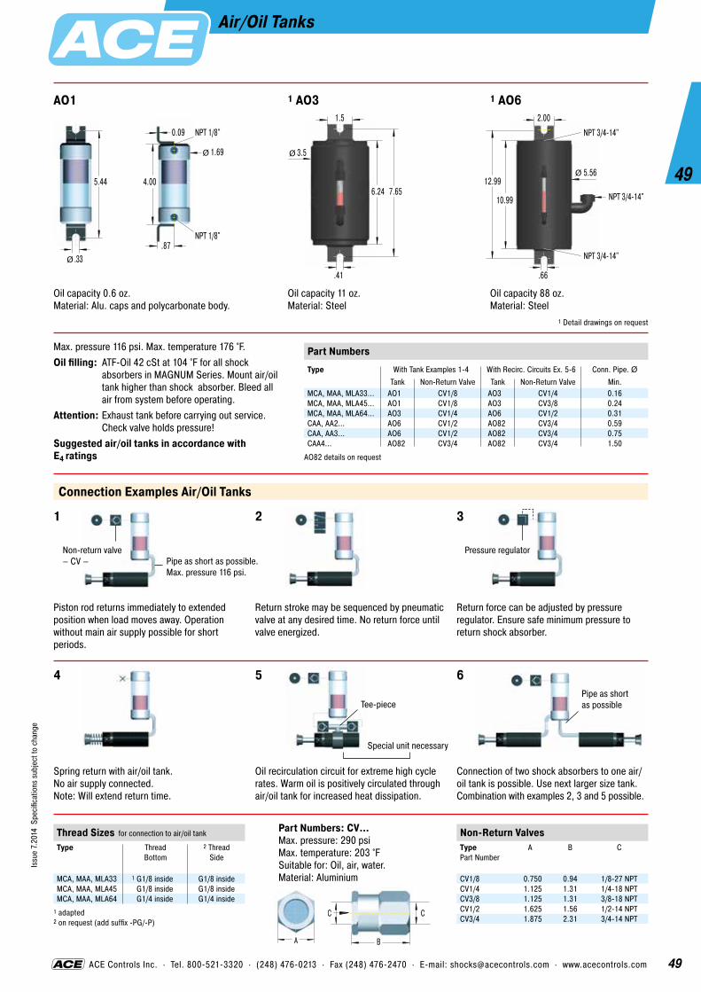
49
49
Issu
e 7.
2014
Spe
cific
atio
ns s
ubje
ct to
cha
nge
ACE Controls Inc. · Tel. 800-521-3320 · (248) 476-0213 · Fax (248) 476-2470 · E-mail: [email protected] · www.acecontrols.com
Air/Oil Tanks
AO1
Piston rod returns immediately to extended position when load moves away. Operation without main air supply possible for short periods.
Max. pressure 116 psi. Max. temperature 176 °F.Oil filling: ATF-Oil 42 cSt at 104 °F for all shock
absorbers in MAGNUM Series. Mount air/oil tank higher than shock absorber. Bleed all air from system before operating.
Attention: Exhaust tank before carrying out service. Check valve holds pressure!
Suggested air/oil tanks in accordance with E4 ratings
1 AO3 1 AO6
5.44
.33Ø
.87
1.69
0.09
NPT 1/8"
4.00
Ø
NPT 1/8"
A B
CC
Connection Examples Air/Oil Tanks
1 2 3
Return stroke may be sequenced by pneumatic valve at any desired time. No return force until valve energized.
Return force can be adjusted by pressure regulator. Ensure safe minimum pressure to return shock absorber.
Non-return valve – CV – Pipe as short as possible.
Max. pressure 116 psi.
Pressure regulator
4 5 6Pipe as shortas possibleTee-piece
Special unit necessary
Spring return with air/oil tank. No air supply connected. Note: Will extend return time.
Oil recirculation circuit for extreme high cycle rates. Warm oil is positively circulated through air/oil tank for increased heat dissipation.
Connection of two shock absorbers to one air/oil tank is possible. Use next larger size tank. Combination with examples 2, 3 and 5 possible.
Part Numbers: CV…Max. pressure: 290 psiMax. temperature: 203 °FSuitable for: Oil, air, water. Material: Aluminium
Oil capacity 0.6 oz.Material: Alu. caps and polycarbonate body.
Oil capacity 11 oz.Material: Steel
Oil capacity 88 oz.Material: Steel
1 Detail drawings on request
.41
3.5
6.24
Ø
7.65
1.5
.66
5.56
10.99
Ø12.99
2.00
NPT 3/4-14"
NPT 3/4-14"
NPT 3/4-14"
Non-Return ValvesType Part Number
A B C
CV1/8 0.750 0.94 1/8-27 NPTCV1/4 1.125 1.31 1/4-18 NPTCV3/8 1.125 1.31 3/8-18 NPTCV1/2 1.625 1.56 1/2-14 NPTCV3/4 1.875 2.31 3/4-14 NPT
Thread Sizes for connection to air/oil tank
Type
Thread Bottom
2 Thread Side
MCA, MAA, MLA33 1 G1/8 inside G1/8 insideMCA, MAA, MLA45 G1/8 inside G1/8 insideMCA, MAA, MLA64 G1/4 inside G1/4 inside
1 adapted 2 on request (add suffix -PG/-P)
Part NumbersType With Tank Examples 1-4 With Recirc. Circuits Ex. 5-6 Conn. Pipe. Ø
Tank Non-Return Valve Tank Non-Return Valve Min.MCA, MAA, MLA33... AO1 CV1/8 AO3 CV1/4 0.16MCA, MAA, MLA45... AO1 CV1/8 AO3 CV3/8 0.24MCA, MAA, MLA64... AO3 CV1/4 AO6 CV1/2 0.31CAA, AA2... AO6 CV1/2 AO82 CV3/4 0.59CAA, AA3... AO6 CV1/2 AO82 CV3/4 0.75CAA4... AO82 CV3/4 AO82 CV3/4 1.50
AO82 details on request

50
50
Issu
e 7.
2014
Spe
cific
atio
ns s
ubje
ct to
cha
nge
Heavy Industrial Shock Absorbers CA2 to CA4Self-Compensating
Positive stop: Install mechanical stop 0.09 inch before the end of stroke.Impact velocity range: 1 up to 16.5 ft/secOperating fluid: Automatic Transmission Fluid (ATF)Material: Body and accessories: Steel with black oxide finish. Piston rod: Steel hardened and chrome plated. Rod end button: Steel hardened with black oxide finish. Return spring: Zinc plated. For optimum heat dissipation do not paint outer body.Capacity rating: For emergency use only applications it may be possible to exceed published en- ergy per cycle (E3) figures. Please consult ACE for further details.Mounting: In any positionOperating temperature range: 10 °F to 150 °FOn request: Special oils, or for higher or lower impact velocities outside range shown above, or other options please consult ACE.
The CA2 to CA4 complete the ACE product range of self-compensating shock absorbers. With these units ACE has a continuous range of self-compensating units to handle effective weights from 1,600 lbs up to 720,000 lbs. The robust CA series units are designed for extremely heavy duty applications. Damage caused by errors in adjustment setting is ruled out by their self-compensating design. You can select the correct model for your application using the ACE Selection Program or by using the capacity chart. The CA units are mainte-nance-free and self-contained with an energy capacity of up to 1,119,618 lbs.
Return Spring
Piston Rod
Main Bearing
Accumulator
Piston
Outer BodyPressure Chamberwith Metering Orifices
Rod Button
Rod Seals

51
51
Issu
e 7.
2014
Spe
cific
atio
ns s
ubje
ct to
cha
nge
Heavy Industrial Shock Absorbers A1½ to A3Adjustable
Positive stop: Install mechanical stop 0.09 inch before the end of stroke.Adjustment: Turning the adjustment screw towards “0” makes the unit harder and towards “9” makes it softer.Impact velocity range: 0.5 to 15 ft/sec Operating fluid: Models A1½: American 46. Models A2 and A3: Automatic Transmission Fluid (ATF).Material: Body and accessories: Steel with black oxide finish. Piston rod: Steel hardened and chrome plated. Rod end button: Steel hardened with black oxide finish. Return spring: Zinc plated. For optimum heat dissipation do not paint outer body.Capacity rating: For emergency use only applications it may be possible to exceed published en- ergy per cycle (E3) figures. Please consult ACE for further details.Mounting: In any positionOperating temperature range: 10 °F to 150 °FOn request: Special oils, or for higher or lower impact velocities outside range shown above, or other options please consult ACE.
The adjustable shock absorbers of the ACE product series A1½ to A3 cover an effective weight range from 430 lbs up to 450,000 lbs. The robust A series units are designed for extremely heavy duty applications. The units are adjusted by means of a socket head screw in the rear end. The adjustable A series can replace the older SAHS series units with the same mounting dimensions. (Ask ACE for assistance.) The A units are maintenance-free and self-contained.
Return Spring
Piston Rod
Main Bearing
Accumulator
Piston
Outer BodyPressure Chamberwith Metering Orifices
Adjustment
Rod Button
Rod Seals

52
52
Issu
e 7.
2014
Spe
cific
atio
ns s
ubje
ct to
cha
nge
ACE Controls Inc. · Tel. 800-521-3320 · (248) 476-0213 · Fax (248) 476-2470 · E-mail: [email protected] · www.acecontrols.com
Heavy Industrial Shock Absorbers A1½Adjustable
L1.75 Stroke 4.00
3.00
0.53Ø
Rear Flange -R
L2.75 Stroke 4.00
3.00
0.53Ø
Front Flange -F
Foot Mounting -S
Not available on 2" stroke models.
L4.63 StrokeL3
5.50
2.00.53
6.50
.75
4.00
Ø
Clevis Mounting -C
Due to limited force capacity the respective ability should be reviewed by ACE.
1.25
.75.75
.75
.63
5/8 1.50
L5 minmax
ØØ
Install mechanical stop 0.09 inch before end of stroke.
Ordering Example A1½x2RAdjustableBore Size Ø 1½"Stroke Length 2" (50.8 mm)Rear Flange Mounting
Model Type PrefixA = self-contained with return spring
(This is standard model)AA = air/oil return without return spring.
Use only with external air/oil tank.NA = self-contained without return springSA = air/oil return with return spring.
Use only with external air/oil tank.
DimensionsType
Stroke inches
L1
L2
L3
L4
L5
A1½x2 2.00 7.69 2.13 – – 10.94 - 12.94A1½x3½ 3.50 9.19 2.13 6.69 2.31 12.46 - 15.97A1½x5 5.00 10.69 2.13 8.19 2.31 13.97 - 18.97A1½x6½ 6.50 12.94 2.88 9.69 3.06 16.22 - 22.72
Capacity ChartMax. Energy Capacity 1 Effective Weight We
Type
2 E3 in-lbs/Cycle
3 E4 Self-Contained
in-lbs/h
3 E4 with Air/Oil Tank
in-lbs/h
We min. lbs
We max. lbs
Min. Return Force
lbs
Max. Return Force
lbs
Rod Reset Time
sec
Max. Side Load Angle
°
Weight lbs
A1½x2 21,000 3,200,000 4,000,000 430 70,000 34.9 47.6 0.1 5 16.4A1½x3½ 36,750 5,600,000 7,000,000 480 80,000 25.4 47.6 0.25 4 19.4A1½x5 52,500 8,000,000 10,000,000 500 90,000 20.7 52.5 0.4 3 22.7A1½x6½ 68,250 10,400,000 13,000,000 680 100,000 20.7 97.4 0.4 2 25.0
1 The effective weight range limits can be raised or lowered to special order. 2 For emergency use only applications it may be possible to exceed these max. capacity ratings. Please consult ACE for further details. 3 Figures for oil recirculation systems on request.

53
53
Issu
e 7.
2014
Spe
cific
atio
ns s
ubje
ct to
cha
nge
ACE Controls Inc. · Tel. 800-521-3320 · (248) 476-0213 · Fax (248) 476-2470 · E-mail: [email protected] · www.acecontrols.com
Heavy Industrial Shock Absorbers CA2 and A2Self-Compensating and Adjustable
A max.75
Stroke.75 B max
Ø 1.38
E
5.50
.66
4.38
Ø
Adjuster – model A2 only
Rear Flange -R
A max.75 .75 B max
Ø 4.25 (4.65)
M100x2
5.50
.66
4.38
Ø
Adjuster – model A2 onlyDimension in ( ) for model A2 only
Front Flange -F
.60 .62C D max 6.50
8.00
1.503.13
2.75
5.50
.66
2" Bore Foot Mount -S
Ordering Example CA2x4F-3Self-CompensatingBore Size Ø 2"Stroke Length 4" (102 mm)Front Flange MountingEffective Weight Range Version
Model Type PrefixA, CA = self-contained with return spring
(This is standard model)AA, CAA = air/oil return without return spring.
Use only with external air/oil tank.NA, CNA = self-contained without return springSA, CSA = air/oil return with return spring.
Use only with external air/oil tank.
DimensionsType
Stroke inches
A max
B max
C
D max
E
G H
2x2 2.00 12.37 4.37 9.28 3.74 2.73 17.05 6.052x4 4.00 16.37 6.31 11.28 5.74 2.73 21.05 8.052x6 6.00 20.37 8.37 13.28 7.74 2.73 25.05 10.052x8 8.00 25.37 11.37 15.28 10.74 3.63 29.05 12.052x10 10.00 29.37 13.37 17.28 12.74 4.25 33.05 14.05
Capacity Chart CA2Max. Energy Capacity 1 Effective Weight We
Soft HardType
2 E3 in-lbs/Cycle
3 E4 Self-Con-
tained in-lbs/h
3 E4 with Air/Oil Tank
in-lbs/h
-1 min. max.
lbs
-2 min. max.
lbs
-3 min. max.
lbs
-4 min. max.
lbs
Min. Return Force lbs
Max. Return Force lbs
Rod Reset Time sec
Max. Side Load
Angle °
Weight lbs
CA2x2 32,000 9,600,000 12,000,000 1,600- 4,800 4,000-12,000 10,000- 30,000 25,000- 75,000 48 63 0.25 3 28.2CA2x4 64,000 12,000,000 15,000,000 3,200- 9,600 8,000-24,000 20,000- 80,000 50,000-150,000 34 63 0.5 3 32.6CA2x6 96,000 14,400,000 18,000,000 4,800-14,400 12,000-36,000 30,000- 90,000 75,000-225,000 34 90 0.6 3 37.2CA2x8 128,000 16,800,000 21,000,000 6,400-19,200 16,000-48,000 40,000-120,000 100,000-300,000 51 144 0.7 3 42.6CA2x10 160,000 19,200,000 24,000,000 8,000-24,000 20,000-60,000 50,000-150,000 125,000-375,000 35 101 0.8 3 50.2
Capacity Chart A2Max. Energy Capacity 1 Effective Weight We
Type
2 E3 in-lbs/Cycle
3 E4 Self-Contained
in-lbs/h
3 E4 with Air/Oil Tank
in-lbs/h
me min. lbs
me max. lbs
Min. Return Force
lbs
Max. Return Force
lbs
Rod Reset Time
sec
Max. Side Load Angle
°
Weight lbs
A2x2 32,000 9,600,000 12,000,000 560 170,000 48 63 0.25 3 31.5A2x4 80,000 12,000,000 15,000,000 560 180,000 34 63 0.5 3 36.9A2x6 120,000 14,400,000 18,000,000 570 190,000 34 90 0.6 3 42.6A2x8 170,000 16,800,000 21,000,000 580 200,000 51 144 0.7 3 49.1A2x10 210,000 19,200,000 24,000,000 720 250,000 35 101 0.8 3 57.8
1 The effective weight range limits can be raised or lowered to special order. 2 For emergency use only applications it may be possible to exceed these max. capacity ratings. Please consult ACE for further details. 3 Figures for oil recirculation systems on request.
1.50
3.50
2.00
1.501.00
2.50
2.04.96
1.251.75
1.002-1.005
5.50
2.25
1.50
.66
G
H
1.002-1.005
4.38
Clevis Mount -C

54
54
Issu
e 7.
2014
Spe
cific
atio
ns s
ubje
ct to
cha
nge
ACE Controls Inc. · Tel. 800-521-3320 · (248) 476-0213 · Fax (248) 476-2470 · E-mail: [email protected] · www.acecontrols.com
Heavy Industrial Shock Absorbers CA3 and A3Self-Compensating and Adjustable
A max1.00
Stroke1.00 B max
Ø 1.75
4.38
6.50
.66
5.38
Ø
Adjuster – model A3 only
4.886.00
M130x2
Rear Flange -R
A max1.00 1.00 B max
Ø 5.50 (6.10)
M130x2
6.50
.66
5.38
Ø
Adjuster – model A3 onlyDimension in ( ) for model A3 only
4.886.00
Front Flange -F
C1.75 .75
D max1.00
3.15
3.151.73
8.5010.00
.66Ø
Adjuster – model A3 only
Foot Mounting -S
Ordering Example A3x8RAdjustableBore Size Ø 3"Stroke Length 8" (203 mm)Rear Flange Mounting
Model Type PrefixA, CA = self-contained with return spring
(This is standard model)AA, CAA = air/oil return without return spring.
Use only with external air/oil tank.NA, CNA = self-contained without return springSA, CSA = air/oil return with return spring.
Use only with external air/oil tank.
DimensionsType
Stroke inches
A max
B max
C
D max
G H
3x5 5.00 19.31 8.31 9.95 8.81 23.05 9.053x8 8.00 25.31 11.31 12.95 11.81 29.05 12.053x12 12.00 35.09 17.09 16.95 17.59 38.83 17.83
Capacity Chart CA3Max. Energy Capacity 1 Effective Weight We
Soft HardType
2 E3 in-lbs/Cycle
3 E4 Self-Contained in-lbs/h
3 E4 with Air/Oil Tank
in-lbs/h
-1 min. max.
lbs
-2 min. max.
lbs
-3 min. max.
lbs
-4 min. max.
lbs
Min. Return Force lbs
Max. Return Force lbs
Rod Reset Time
sec
Max. Side Load Angle
°
Weight lbs
CA3x5 125,000 20,000,000 25,000,000 6,400-19,200 16,000- 48,000 40,000-120,000 100,000-300,000 59 156 0.6 3 63.8CA3x8 200,000 32,000,000 40,000,000 10,240-30,720 25,600- 76,800 64,000-192,000 160,000-480,000 62 162 0.8 3 73.6CA3x12 300,000 48,000,000 60,000,000 15,360-46,080 38,400-115,200 96,000-288,000 240,000-720,000 60 160 1.2 3 89.4
Capacity Chart A3Max. Energy Capacity 1 Effective Weight We
Type
2 E3 in-lbs/Cycle
3 E4 Self-Contained
in-lbs/h
3 E4 with Air/Oil Tank
in-lbs/h
me min. lbs
me max. lbs
Min. Return Force lbs
Max. Return Force lbs
Rod Reset Time
sec
Max. Side Load Angle
°
Weight lbs
A3x5 140,000 20,000,000 25,000,000 1,050 340,000 59 156 0.6 3 72.1A3x8 250,000 32,000,000 40,000,000 1,200 400,000 62 162 0.8 3 84.9A3x12 390,000 48,000,000 60,000,000 1,350 450,000 60 160 1.2 3 105.0
1 The effective weight range limits can be raised or lowered to special order. 2 For emergency use only applications it may be possible to exceed these max. capacity ratings. Please consult ACE for further details. 3 Figures for oil recirculation systems on request.
1.50
3.50
2.00
1.501.00
1.12
2.04.96
1.251.75
1.002-1.005
6.50
2.25
1.50
.66
G
H
1.005
4.88
5.38
Clevis Mount -C

55
55
Issu
e 7.
2014
Spe
cific
atio
ns s
ubje
ct to
cha
nge
ACE Controls Inc. · Tel. 800-521-3320 · (248) 476-0213 · Fax (248) 476-2470 · E-mail: [email protected] · www.acecontrols.com
Heavy Industrial Shock Absorbers CA4Self-Compensating
A max
2.12 (2.50)
B max1.50 7.50
4.50 (5.00)
Ø
Ø
Ø
Stroke
10.008.00
1.06Ø
Dimension in ( ) for model CA4x16 only
Rear Flange -R
C maxD max1.50
10.008.00
1.06Ø
Front Flange -F
.63
C maxB max
1-1/2"-11 NPT
.79
4.00
.37
Ø
6 x 60°
6.25
UNF 5/8"-18
6 Tapped Holes (Primary Mounting) FRP
1.06
E.87
.87 F max
Ø4.49
8.036.50
2.76
Foot Mounting -S
Ordering Example CA4x8R-5Self-CompensatingBore Size Ø 4"Stroke Length 8" (203 mm)Rear Flange MountingEffective Weight Range Version
Model Type PrefixCA = self-contained with return spring
(This is standard model)CAA = air/oil return without return spring.
Use only with external air/oil tank.CNA = self-contained without return springCSA = air/oil return with return spring.
Use only with external air/oil tank.
Capacity Chart CA4Max. Energy Capacity 1 Effective Weight We
Soft HardType
2 E3 in-lbs/Cycle
E4 Self-Contained in-lbs/h
E4 with Air/Oil Tank
in-lbs/h
E4 with Oil Recirculation
in-lbs/h
-3 min. max.
lbs
-5 min. max.
lbs
-7 min. max.
lbs
Min. Return Force lbs
Max. Return Force lbs
Rod Reset Time
sec
Weight lbs
CA4x6 420,000 27,000,000 45,000,000 58,400,000 8,000 - 19,000 19,000 - 41,000 41,000 - 94,000 108 222 1.8 132CA4x8 560,000 30,000,000 50,000,000 64,600,000 11,000 - 25,000 25,000 - 55,000 55,000 - 125,000 71 222 2.3 150CA4x16 1,120,000 50,000,000 85,000,000 109,800,000 22,000 - 50,000 50,000 - 110,000 110,000 - 250,000 71 222 Ask 321
1 The effective weight range limits can be raised or lowered to special order. 2 For emergency use only applications it may be possible to exceed these max. capacity ratings. Please consult ACE for further details.
Dimensions CA/CNA/CSAType
Stroke inches
A
B
C
D
E
F
G H
4x6 6.00 28.21 10.96 26.71 9.46 17.50 10.09 31.03 - 33.03 10.90 - 12.904x8 8.00 32.21 12.96 30.71 11.46 19.50 12.09 35.03 - 37.03 12.90 - 14.904x16 16.00 51.21 23.96 49.71 22.46 27.50 23.09 51.03 - 56.03 20.90 - 25.90
Dimensions of model CAA available on request.
3.50
2.49
2.002 2.002
1.682.32
GH
2.241.682.49
3.50
minmax
minmax
Clevis Mount -C

56
56
Issu
e 7.
2014
Spe
cific
atio
ns s
ubje
ct to
cha
nge
ACE Controls Inc. · Tel. 800-521-3320 · (248) 476-0213 · Fax (248) 476-2470 · E-mail: [email protected] · www.acecontrols.com
2 Side load adaptor for high side load angles
5 Double acting shock absorber
6 Air bleed collar
With heavy loads or high velocities normal cylinder cushions are often overloaded. This causes shock loading leading to premature cylinder failure or excessive maintenance. Using oversized cylinders to withstand this shock loading is not the best solution since this considerably increases air consumption and costs.
The side loading is removed from the shock absorber piston rod leading to considerably longer life. See page 36 for more details.
The lever 1 swings with the pin 2 in a slotted hole around pivot point 3. The lever is smoothly decelerated at the extreme end of its travel.
It is possible to use only one shock absorber for both end positions by using different pivot points as shown.Tip: Leave approx. 0.06 inches of shock absorber stroke free at each end of travel.
With a little additional work a normal uni- directional shock absorber can be converted to work in 2 directions by using a mecha-nism as shown.
By using the air bleed adaptor the operat- ing lifetime of shock absorbers in aggres-sive environments can be considerably increased. The adaptor protects the shock absorber seals from cutting fluids, cleaning agents, cooking oil, etc. by using a low pressure air bleed.
1
2
3
Free Travel
Rs
αStroke s
Pivot Point of Lever
Shock Absorber Stroke Shock Absorber Stroke
Seal with Teflon Tape or Sealant
Installation Examples
For: optimum deceleration higher speeds smaller cylinders reduced air consumption smaller valves and pipework
Example: MA3350-Z (cylinder mounting)
4 One shock absorber for both ends of travel
3 Undamped free travel with damped end position
1 ACE Shock absorbers for pneumatic cylinders

57
57
Issu
e 7.
2014
Spe
cific
atio
ns s
ubje
ct to
cha
nge
ACE Controls Inc. · Tel. 800-521-3320 · (248) 476-0213 · Fax (248) 476-2470 · E-mail: [email protected] · www.acecontrols.com
Installation Examples
7 Double stroke length
10 Adjustable stop clamp e.g. for handling equipment
12 Increasing stroke length mechanically
8.1 8.2
50% lower reaction force (Q)50% lower deceleration (a)By driving 2 shock absorbers against one another ‘nose-to-nose’, the effective stroke length can be doubled.
8.1 The latch absorbs the kinetic energy so that the object contacts the fixed stop gently.8.2 The latch absorbs the rotational energy of the turntable etc. The turntable can then be held in the datum position with a lock bolt or similar.
The use of ACE shock absorbers allows higher operating speeds and weights as well as protecting the drive mechanism and housing from shock loads.
The gentle deceleration of ACE shock absorbers makes the use of adjustable stop clamps possible and removes any chance of the clamp slipping. The kinetic energy is completely removed before the mechanical stop is reached thus making high index speeds possible.
The fire door travels quickly until it reaches the lever. It is then gently decelerated by the lever mounted shock absorber and closes without shock or danger to personnel.
By means of a lever the effective stroke length can be increased and mounting space to the left reduced.
Stroke
9 Rotary actuator or rack and pinion drive
Door
Safety Travel(prevents trapping)
11 Ride-over latch e.g. fire door
8 Ride over latch

58
58
Issu
e 7.
2014
Spe
cific
atio
ns s
ubje
ct to
cha
nge
ACE Controls Inc. · Tel. 800-521-3320 · (248) 476-0213 · Fax (248) 476-2470 · E-mail: [email protected] · www.acecontrols.com
Miniature Shock AbsorbersApplication Examples
Rs
αStroke s
Constant resisting force
Soft end-of-travel dampingon rotary movements
ACE miniature shock absorbers are the right alternative. This pneumatic module for high precision, high speed motion intentionally abandoned pneumatic end-of-travel damping. The compact miniature shock absorbers of the type MC25MH-NB decelerate the linear motion safer and faster when reaching the end-of-travel position. They accept the moving load gently and decelerate it smoothly throughout the entire stroke length. Additional advantages: simpler construction, smaller pneumatic valves, lower maintenance costs as well as reduced compressed air consumption.
ACE miniature shock absorbers optimize production with minimum expenditure. The cycle rate for an assembly line producing electronic com- ponents was increased to 3600 units/hr by using ACE shock ab- sorbers. Miniature shock absorbers type SC190M-1 decelerate the rapid transfer movements on the production line and using soft damping methods optimize the pick up and set down of components. This soft deceleration technique has increased production and reduced maintenance on the portal and rotary actuator modules. The optional side load adaptor protects the shock absorber from high side load forces and increases the operating lifetime. Using ACE shock absorbers reduces mainte-nance costs by 50% and running costs by 20%, diminishing energy consumption.
Miniature shock absorber in linear pneumatic module
Optimized production in the electronics industry

59
59
Issu
e 7.
2014
Spe
cific
atio
ns s
ubje
ct to
cha
nge
ACE Controls Inc. · Tel. 800-521-3320 · (248) 476-0213 · Fax (248) 476-2470 · E-mail: [email protected] · www.acecontrols.com
Industrial Shock AbsorbersApplication Examples
Safe swiveling
Quicker, gentlepositioning
ACE industrial shock absorbers offer safety to spare for rotation or braking of a large telescope. The optical system of this telescope for special observations is moveable in two space coordinates. The structure in which the telescope is mounted weighs 33,069 lbs and consists of a turn- table with drives and two wheel disks rotating on bearings. It enables a rotation by ±90° from horizon to horizon. To safeguard the telescope in case of overshooting the respective swiveling limits, industrial shock absorbers of the type ML3325M are used as braking elements. Should the telescope inadvertently overshoot the permissible swivel range, they will safely damp the travel of the valuable telescope.
ACE industrial shock absorbers optimize portal for machine loading and increase productivity. This device driven by piston rodless pneumatic cylinders, in which two gripper slides are moving independently of each other at speeds of 6.56 ft/sec to 8.20 ft/sec, is equipped with industrial shock absorbers as brake systems. Their function is to stop a mass of 55 lbs up to 540 times per hour. The model MC3350M-1-S was chosen for this application, allowing easy and extremely accurate adjustment of the end positions of the adjustable limit stops. In comparison to brake systems with other function prin- ciples, shock absorbers allow higher travel speeds and shorter cycle sequences.
Perfect overshoot protection for precision telescope
Industrial shock absorbers optimize portal operation

60
60
Issu
e 7.
2014
Spe
cific
atio
ns s
ubje
ct to
cha
nge
Safety Shock Absorbers SCS33 to SCS64
Impact cycles per hour: max. 1Life expectancy: Self-compensating version: max. 1000 cycles. Optimized version: max. 5 cycles.Impact velocity range: On requestOperating fluid: Automatic Transmission Fluid (ATF)Material: Shock absorber body: Nitride hardened steel. Accessories: Steel with black oxide finish. Piston rod: Steel hardened and chrome plated. Rod end button: Hardened steel with black oxide finish. Return Spring: Zinc plated or plastic-coated.Energy capacity E3: At max. side load angle do not exceed 80 % of rated max. energy capacity below.Mounting: In any positionOperating temperature range: 10 °F to 158 °F. For higher and lower temperatures consult ACE.In creep speed: The shock absorber can be pushed through its stroke. In creep speed conditions the shock absorber provides minimal resistance and there is no braking effect.
Based on the innovative design concepts of the MAGNUM range, ACE introduces the SCS33 to SCS64 series of safety shock absorb-ers. Designed to provide machine protection in an emergency runaway situation the SCS33 to SCS64 series provide a cost effective method of protecting vital machinery in emergency stop situations. Specially optimized orificing design provides extremely high capacity in a compact envelope size making them ideal for critical applications on portal gantry systems, automatic transfer machines and robot systems where an emergency runaway could otherwise result in expensive damage or danger. With up to 300 % higher capacity than other shock absorber designs the SCS33 to 64 range provides true linear deceleration protecting vital equipment at an affordable cost. Integrated
Positive Stop
Main Bearing
Fully Threaded Outer Body
Membrane Accumulator
Piston
Unique Identification Code Number
One Piece Pressure Chamberwith Optimized Metering Orificesto Suit Specific Application
Piston Ring
Heavy Duty One-Piece Steel Outer Body
Rod Button
Rod Seals

61
61
Issu
e 7.
2014
Spe
cific
atio
ns s
ubje
ct to
cha
nge
ACE Controls Inc. · Tel. 800-521-3320 · (248) 476-0213 · Fax (248) 476-2470 · E-mail: [email protected] · www.acecontrols.com
Safety Shock Absorbers SCS33
M33x1.5
Positive Stop
Stroke1.18
1.00
BA max
Ø
Ø
Standard Dimensions
250-0151
Side Foot Mounting Kit S33 = 2 flanges + 4 screws M6x40, DIN 912 Because of the thread pitch the fixing holes for the second foot mount should only be drilled and tapped after the first foot mount has been fixed in position.
Tightening torque: 8.1 ft-lbs (screws) Clamping torque: > 66.4 ft-lbs
C D.39.79max
minM6
1.65
2.20
.79
1.57
.31
.31
250-0659
Square Flange Install with 4 machine screws Tightening torque: 8.1 ft-lbs Clamping torque: > 66.4 ft-lbs
1.73
Thickness.39
ClampingSlot
1.26
.26Ø
250-0292
Locking Ring
.25
1.56Ø
The calculation and selection of the correct ACE safety shock absorber for your application should be referred to ACE for approval and assignment of unique identification number.
Ordering Example SCS33-50-1xxxxSafety Shock AbsorberThread Size M33Max. Stroke without Positive Stop 1.97" (50 mm)Identification No. assigned by ACEPlease indicate identification no. in case of replacement order
Complete Details Required when OrderingMoving load W (lbs)Impact velocity range v (ft/sec) max.Creep speed vs (ft/sec)Motor power HP (horsepower)Stall torque factor ST (normal 2.5)Number of absorbers in parallel n
or technical data according to formulae and calculations on page 11 to 13.
Dimensions and Capacity ChartMax. Energy Capacity
Self-Compensating Optimized VersionType Stroke
inchesA max
inches B
inchesC min
inches C max inches
D inches
E3 in-lbs/Cycle
E3 in-lbs/Cycle
Min. Return Force lbs
Max. Return Force lbs
Max. Side Load Angle
°
Weight lbs
SCS33-25 0.91 5.44 3.27 0.98 2.36 2.68 2,744 4,425 10.1 20.2 3 1.00SCS33-50 1.91 7.44 4.25 1.26 3.39 3.66 5,487 8,408 10.1 30.3 2 1.20
For other stroke lengths, special options (such as higher or lower impact velocity etc.), please consult ACE.

62
62
Issu
e 7.
2014
Spe
cific
atio
ns s
ubje
ct to
cha
nge
ACE Controls Inc. · Tel. 800-521-3320 · (248) 476-0213 · Fax (248) 476-2470 · E-mail: [email protected] · www.acecontrols.com
Safety Shock Absorbers SCS45
M45x1.5
Positive Stop
Stroke1.65
1.38
BA max
Ø
Ø
Standard Dimensions
250-0683
Side Foot Mounting Kit S45 = 2 flanges + 4 screws M8x50, DIN 912 Because of the thread pitch the fixing holes for the second foot mount should only be drilled and tapped after the first foot mount has been fixed in position.
Tightening torque: 19.9 ft-lbs (screws) Clamping torque: > 258 ft-lbs
C D.49.98max
minM8
2.36
3.15
1.10
2.20
.39
.63
250-0689
Square Flange Install with 4 machine screws Tightening torque: 19.9 ft-lbs Clamping torque: > 147.5 ft-lbs
2.20
Thickness.47
ClampingSlot
1.65
.35Ø
250-0297
Locking Ring
.37
2.25Ø
The calculation and selection of the correct ACE safety shock absorber for your application should be referred to ACE for approval and assignment of unique identification number.
Ordering Example SCS45-50-1xxxxSafety Shock AbsorberThread Size M45Max. Stroke without Positive Stop 1.97" (50 mm)Identification No. assigned by ACEPlease indicate identification no. in case of replacement order
Complete Details Required when OrderingMoving load W (lbs)Impact velocity range v (ft/sec) max.Creep speed vs (ft/sec)Motor power HP (horsepower)Stall torque factor ST (normal 2.5)Number of absorbers in parallel n
or technical data according to formulae and calculations on page 11 to 13.
Dimensions and Capacity ChartMax. Energy Capacity
Self-Compensating Optimized VersionType Stroke
inchesA max
inches B
inchesC min
inchesC max inches
D inches
E3 in-lbs/Cycle
E3 in-lbs/Cycle
Min. Return Force lbs
Max. Return Force lbs
Max. Side Load Angle
°
Weight lbs
SCS45-25 0.91 5.71 3.74 1.26 2.60 2.60 6,019 10,621 15.7 22.5 3 2.49SCS45-50 1.91 7.68 4.72 1.57 3.58 3.58 12,037 20,799 15.7 32.6 2 3.00SCS45-75 2.91 9.69 5.71 1.97 4.65 4.57 18,056 30,978 11.2 40.5 1 3.51
For other stroke lengths, special options (such as higher or lower impact velocity etc.), please consult ACE.

63
63
Issu
e 7.
2014
Spe
cific
atio
ns s
ubje
ct to
cha
nge
ACE Controls Inc. · Tel. 800-521-3320 · (248) 476-0213 · Fax (248) 476-2470 · E-mail: [email protected] · www.acecontrols.com
Safety Shock Absorbers SCS64
M64x2
Positive Stop
Stroke
Note: 5.91" stroke model does not include stop collar and positive stop is provided by the rod button (Ø 2.36")
2.36
1.89
BA max
Ø
Ø
Standard Dimensions
250-0693
Side Foot Mounting Kit S64 = 2 flanges + 4 screws M10x80, DIN 912 Because of the thread pitch the fixing holes for the second foot mount should only be drilled and tapped after the first foot mount has been fixed in position.
Tightening torque: 37 ft-lbs (screws) Clamping torque: > 258 ft-lbs
C D.49.98max
minM10
3.07
3.94
1.57
3.15
.47
.47
250-0172
Square Flange Install with 4 machine screws Tightening torque: 37 ft-lbs Clamping torque: > 155 ft-lbs
3.15
Thickness.63
ClampingSlot
2.28
.43Ø
250-0301
Locking Ring
.37
3.00Ø
The calculation and selection of the correct ACE safety shock absorber for your application should be referred to ACE for approval and assignment of unique identification number.
Ordering Example SCS64-50-1xxxxSafety Shock AbsorberThread Size M64Max. Stroke without Positive Stop 1.97" (50 mm)Identification No. assigned by ACEPlease indicate identification no. in case of replacement order
Complete Details Required when OrderingMoving load W (lbs)Impact velocity range v (ft/sec) max.Creep speed vs (ft/sec)Motor power HP (horsepower)Stall torque factor ST (normal 2.5)Number of absorbers in parallel n
or technical data according to formulae and calculations on page 11 to 13.
Dimensions and Capacity ChartMax. Energy Capacity
Self-Compensating Optimized VersionType
Stroke inches
A max inches
B inches
C min inches
C max inches
D inches
E3 in-lbs/Cycle
E3 in-lbs/Cycle
Min. Return Force lbs
Max. Return Force lbs
Max. Side Load Angle
°
Weight lbs
SCS64-50 1.91 8.86 5.51 1.97 4.41 3.94 30,093 53,104 20.2 34.8 3 7.01SCS64-100 3.92 12.83 7.52 2.52 6.38 5.98 60,185 106,209 23.6 60.7 2 9.26SCS64-150 5.91 17.72 9.49 3.15 8.35 8.90 90,278 159,313 16.9 82.1 1 12.46
For other stroke lengths, special options (such as higher or lower impact velocity etc.), please consult ACE.

64
64
Issu
e 7.
2014
Spe
cific
atio
ns s
ubje
ct to
cha
nge
Safety Shock Absorbers SCS38 to SCS63
Function: In the normal “ready” condition the piston rod is fully extended. When the impact load strikes the absorber the hydraulic oil behind the piston is forced out through a series of metering orifices. The number of metering orifices in action reduces proportionally though the stroke and the load velocity is thereby smoothly reduced to zero. The internal pressure and thus the reaction force (Q) remains constant throughout the entire stroke length. The displaced oil is stored in the bladder accumulator. The integrated gas chamber, containing low pressure nitrogen, provides the return force to reset the rod to its ex- tended position and functions as an accumulator for the hydraulic oil displaced during the operation.Material: Steel body with black oxide finish. Piston rod hard chrome plated.Energy capacity E3: At max. side load angle do not exceed 80 % of rated max. energy capacity below.Filling pressure: Approx. 29 psiOperating temperature range: 10 °F to 150 °FOn request: Integrated rod sensor for indicating the complete extension of the piston rod. Type normally closed or normally open, option PNP or NPN switch.In creep speed: It is possible to use up to approx. 60 % of the buffer stroke. In creep speed conditions the shock absorber provides minimal resistance and there is no braking effect.
ACE safety shock absorbers are self- contained and maintenance-free. They are designed for emergency deceleration and are an economic alternative to industrial shock absorbers. The SCS series units are available with operating strokes up to 47.24" and are specially orificed to provide a smooth constant deceleration throughout their entire stroke length. The internal hydraulic pressure and thus the braking force, is maintained at a con- stant safe level to bring the fast moving load gently to rest in an emergency. Applications specially include conveyor systems, automated storage, cranes and heavy machines. Optional rod sensor available for indicating the complete extension of the piston rod.
Piston Rod
Outer Body
Main Bearing
Gas Accumulator
Bladder Accumulator
Pressure Chamber
Metering Orifices
Positive Stop
Rod Seals
Rod Button
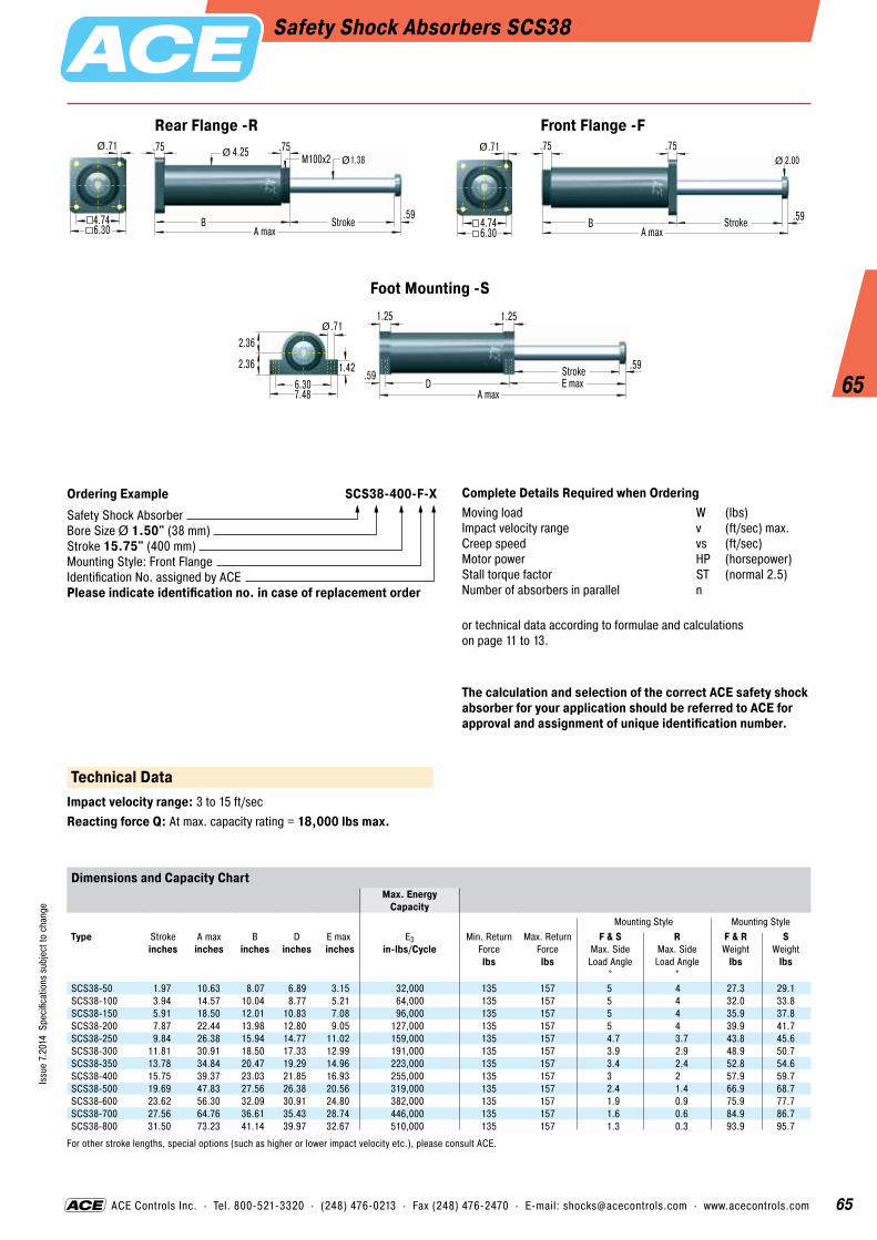
65
65
Issu
e 7.
2014
Spe
cific
atio
ns s
ubje
ct to
cha
nge
ACE Controls Inc. · Tel. 800-521-3320 · (248) 476-0213 · Fax (248) 476-2470 · E-mail: [email protected] · www.acecontrols.com
Safety Shock Absorbers SCS38
1.38.75
B StrokeA max
.59
.75 4.25 M100x2ØØ
4.746.30
.71Ø
Rear Flange -R
4.746.30
.71Ø .75
B StrokeA max
.59
.752.00Ø
Front Flange -F
2.36
2.36 1.426.307.48
.71Ø1.25
A max
.59
1.25
StrokeE maxD
.59
Foot Mounting -S
The calculation and selection of the correct ACE safety shock absorber for your application should be referred to ACE for approval and assignment of unique identification number.
Ordering Example SCS38-400-F-XSafety Shock AbsorberBore Size Ø 1.50" (38 mm)Stroke 15.75" (400 mm)Mounting Style: Front FlangeIdentification No. assigned by ACEPlease indicate identification no. in case of replacement order
Complete Details Required when OrderingMoving load W (lbs)Impact velocity range v (ft/sec) max.Creep speed vs (ft/sec)Motor power HP (horsepower)Stall torque factor ST (normal 2.5)Number of absorbers in parallel n
or technical data according to formulae and calculations on page 11 to 13.
Technical DataImpact velocity range: 3 to 15 ft/secReacting force Q: At max. capacity rating = 18,000 lbs max.
Dimensions and Capacity ChartMax. Energy
CapacityMounting Style Mounting Style
Type
Stroke inches
A max inches
B inches
D inches
E max inches
E3 in-lbs/Cycle
Min. Return Force lbs
Max. Return Force lbs
F & S Max. Side
Load Angle °
R Max. Side
Load Angle °
F & R Weight
lbs
S Weight
lbs
SCS38-50 1.97 10.63 8.07 6.89 3.15 32,000 135 157 5 4 27.3 29.1SCS38-100 3.94 14.57 10.04 8.77 5.21 64,000 135 157 5 4 32.0 33.8SCS38-150 5.91 18.50 12.01 10.83 7.08 96,000 135 157 5 4 35.9 37.8SCS38-200 7.87 22.44 13.98 12.80 9.05 127,000 135 157 5 4 39.9 41.7SCS38-250 9.84 26.38 15.94 14.77 11.02 159,000 135 157 4.7 3.7 43.8 45.6SCS38-300 11.81 30.91 18.50 17.33 12.99 191,000 135 157 3.9 2.9 48.9 50.7SCS38-350 13.78 34.84 20.47 19.29 14.96 223,000 135 157 3.4 2.4 52.8 54.6SCS38-400 15.75 39.37 23.03 21.85 16.93 255,000 135 157 3 2 57.9 59.7SCS38-500 19.69 47.83 27.56 26.38 20.56 319,000 135 157 2.4 1.4 66.9 68.7SCS38-600 23.62 56.30 32.09 30.91 24.80 382,000 135 157 1.9 0.9 75.9 77.7SCS38-700 27.56 64.76 36.61 35.43 28.74 446,000 135 157 1.6 0.6 84.9 86.7SCS38-800 31.50 73.23 41.14 39.97 32.67 510,000 135 157 1.3 0.3 93.9 95.7
For other stroke lengths, special options (such as higher or lower impact velocity etc.), please consult ACE.

66
66
Issu
e 7.
2014
Spe
cific
atio
ns s
ubje
ct to
cha
nge
ACE Controls Inc. · Tel. 800-521-3320 · (248) 476-0213 · Fax (248) 476-2470 · E-mail: [email protected] · www.acecontrols.com
Safety Shock Absorbers SCS50
1.75.75
B StrokeA max
.79
.75 5.12 M120x2Ø
Ø
5.507.09
.71Ø
Rear Flange -R
5.507.09
.71Ø .75
B StrokeA max
.79
.75 2.75Ø
Front Flange -F
2.83
2.83 1.577.488.86
.87Ø1.38
A max
.79
1.38
StrokeE maxD
.69
Foot Mounting -S
The calculation and selection of the correct ACE safety shock absorber for your application should be referred to ACE for approval and assignment of unique identification number.
Ordering Example SCS50-400-F-XSafety Shock AbsorberBore Size Ø 1.97" (50 mm)Stroke 15.75" (400 mm)Mounting Style: Front FlangeIdentification No. assigned by ACEPlease indicate identification no. in case of replacement order
Complete Details Required when OrderingMoving load W (lbs)Impact velocity range v (ft/sec) max.Creep speed vs (ft/sec)Motor power HP (horsepower)Stall torque factor ST (normal 2.5)Number of absorbers in parallel n
or technical data according to formulae and calculations on page 11 to 13.
Technical DataImpact velocity range: 2 to 15 ft/secReacting force Q: At max. capacity rating = 36,000 lbs max.
Dimensions and Capacity ChartMax. Energy
CapacityMounting Style Mounting Style
Type
Stroke inches
A max inches
B inches
D inches
E max inches
E3 in-lbs/Cycle
Min. Return Force lbs
Max. Return Force lbs
F & S Max. Side
Load Angle °
R Max. Side Load Angle
°
F & R Weight
lbs
S Weight
lbs
SCS50-100 3.94 15.35 10.63 9.25 5.41 124,000 225 270 5 4 48.1 51.3SCS50-150 5.91 19.29 12.60 11.22 7.38 186,000 225 270 5 4 53.7 57.0SCS50-200 7.87 23.23 14.57 13.19 9.35 248,000 225 270 5 4 59.1 62.3SCS50-250 9.84 27.17 16.54 15.16 11.32 310,000 225 270 4.5 3.5 64.9 68.1SCS50-300 11.81 31.69 19.09 17.71 13.29 372,000 225 270 3.8 2.8 71.6 74.9SCS50-350 13.78 35.63 21.06 19.69 15.25 434,000 225 270 3.3 2.3 77.2 80.4SCS50-400 15.75 40.16 23.62 22.25 17.22 496,000 225 270 2.9 1.9 84.2 87.5SCS50-500 19.69 48.62 28.15 26.77 21.16 620,000 225 270 2.3 1.3 96.8 100.1SCS50-600 23.62 57.09 32.68 31.30 25.10 743,000 225 270 1.9 0.9 109.4 112.7SCS50-700 27.56 65.55 37.20 35.83 29.03 867,000 225 270 1.6 0.6 122.0 125.2SCS50-800 31.50 74.02 41.73 40.36 32.97 991,000 225 270 1.3 0.3 134.6 137.8SCS50-1000 39.37 90.94 50.79 49.40 40.85 1,239,000 225 270 1 0 159.7 163.0
For other stroke lengths, special options (such as higher or lower impact velocity etc.), please consult ACE.
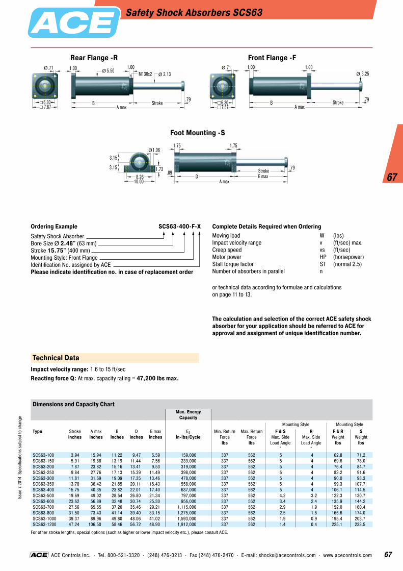
67
67
Issu
e 7.
2014
Spe
cific
atio
ns s
ubje
ct to
cha
nge
ACE Controls Inc. · Tel. 800-521-3320 · (248) 476-0213 · Fax (248) 476-2470 · E-mail: [email protected] · www.acecontrols.com
Safety Shock Absorbers SCS63
2.131.00
B StrokeA max
.79
1.00 5.50 M130x2Ø
Ø
6.307.87
.71Ø
Rear Flange -R
6.307.87
.71Ø 1.00
B StrokeA max
.79
1.00 3.25Ø
Front Flange -F
3.15
3.15 1.738.26
10.00
1.06Ø1.75
A max
.79
1.75
StrokeE maxD
.89
Foot Mounting -S
The calculation and selection of the correct ACE safety shock absorber for your application should be referred to ACE for approval and assignment of unique identification number.
Ordering Example SCS63-400-F-XSafety Shock AbsorberBore Size Ø 2.48" (63 mm)Stroke 15.75" (400 mm)Mounting Style: Front FlangeIdentification No. assigned by ACEPlease indicate identification no. in case of replacement order
Complete Details Required when OrderingMoving load W (lbs)Impact velocity range v (ft/sec) max.Creep speed vs (ft/sec)Motor power HP (horsepower)Stall torque factor ST (normal 2.5)Number of absorbers in parallel n
or technical data according to formulae and calculations on page 11 to 13.
Technical DataImpact velocity range: 1.6 to 15 ft/secReacting force Q: At max. capacity rating = 47,200 lbs max.
Dimensions and Capacity ChartMax. Energy
CapacityMounting Style Mounting Style
Type
Stroke inches
A max inches
B inches
D inches
E max inches
E3 in-lbs/Cycle
Min. Return Force lbs
Max. Return Force lbs
F & S Max. Side
Load Angle °
R Max. Side
Load Angle °
F & R Weight
lbs
S Weight
lbs
SCS63-100 3.94 15.94 11.22 9.47 5.59 159,000 337 562 5 4 62.8 71.2SCS63-150 5.91 19.88 13.19 11.44 7.56 239,000 337 562 5 4 69.6 78.0SCS63-200 7.87 23.82 15.16 13.41 9.53 319,000 337 562 5 4 76.4 84.7SCS63-250 9.84 27.76 17.13 15.39 11.49 398,000 337 562 5 4 83.2 91.6SCS63-300 11.81 31.69 19.09 17.35 13.46 478,000 337 562 5 4 90.0 98.3SCS63-350 13.78 36.42 21.85 20.11 15.43 558,000 337 562 5 4 99.3 107.7SCS63-400 15.75 40.35 23.82 22.01 17.40 637,000 337 562 5 4 106.1 114.5SCS63-500 19.69 49.02 28.54 26.80 21.34 797,000 337 562 4.2 3.2 122.3 130.7SCS63-600 23.62 56.89 32.48 30.74 25.30 956,000 337 562 3.4 2.4 135.9 144.2SCS63-700 27.56 65.55 37.20 35.46 29.21 1,115,000 337 562 2.9 1.9 152.0 160.4SCS63-800 31.50 73.43 41.14 39.40 33.15 1,275,000 337 562 2.5 1.5 165.6 174.0SCS63-1000 39.37 89.96 49.80 48.06 41.02 1,593,000 337 562 1.9 0.9 195.4 203.7SCS63-1200 47.24 106.50 58.46 56.72 48.90 1,912,000 337 562 1.4 0.4 225.1 233.5
For other stroke lengths, special options (such as higher or lower impact velocity etc.), please consult ACE.

68
68
Issu
e 7.
2014
Spe
cific
atio
ns s
ubje
ct to
cha
nge
Safety Shock Absorbers CB63 to CB160For Crane Installations
ACE safety shock absorbers are self- contained and maintenance-free. They are designed for emergency deceleration and are an economic alternative to industrial shock absorbers. The primary oil seals are protected inside the main body and only a wiper seal is necessary on the piston rod. Dirt or contami-nation on the piston rod does not cause oil leakage or failure as is often the case with con- ventional buffers. The integrated gas accumu-lator enables the CB Series safety shock absorbers to provide return forces of up to 15,869 lbs. This high return force is necessary for multiple-bridge cranes where the buffers must separate the bridges after an emergency collision. Normal buffers would remain com- pressed after such a collision and would not be capable of accepting further impacts. The robust, large dimensioned piston rod bearing system, is designed for very heavy duty use and is equivalent to that used in other buffers 80 % larger in size. The CB series units are custom orificed to suit your specific appli- cation and provide a smooth constant decelera-tion throughout their complete stroke length.
Function: In the normal “ready” condition the piston rod is fully extended. When the impact load strikes the absorber the hydraulic oil behind the piston is forced through a series of metering orifices. The number of metering orifices in action reduces proportionally through the stroke and the load velocity is thereby reduced to zero. The internal pressure and thus the reaction force (Q) remains constant throughout the entire stroke length. The displaced oil is directed inside the piston rod where a separator piston keeps the oil and the nitrogen gas apart. The integrated gas accumulator, containing low pressure nitrogen, provides the high return force to reset the rod to its extended position and generates the high return forces to comply with crane installations.Impact velocity range: 1.6 to 15 ft/secMaterial: Steel body with black oxide finish. Piston rod hard chrome plated.Operating temperature range: 10 °F to 150 °FInitial fill pressure: governs the rod return force.In creep speed: The shock absorber can be pushed through its stroke.
Rod Button
Piston Tube
Gas Accumulator
Rod Wiper
Mounting Flange
Hydraulic Oil
Separator Piston
SealsPiston
Metering Orifices
Pressure Chamber
Positive Stop

69
69
Issu
e 7.
2014
Spe
cific
atio
ns s
ubje
ct to
cha
nge
ACE Controls Inc. · Tel. 800-521-3320 · (248) 476-0213 · Fax (248) 476-2470 · E-mail: [email protected] · www.acecontrols.com
Safety Shock Absorbers CB63For Crane Installations
2.38
A max
1.26
3.75M90x2 3.12 3.75 3.75
StrokeC
.751.61
.75
Ø Ø Ø Ø Ø6.50
5.31.71Ø
Ø
Ø
Front Flange -F
A maxStrokeB
6.50
5.31.71Ø
Ø
Ø
Rear Flange -R
The calculation and selection of the correct ACE safety shock absorber for your application should be referred to ACE for approval and assignment of unique identification number.
Ordering Example CB63-400-F-XSafety Shock AbsorberBore Size Ø 2.48" (63 mm)Stroke 15.75" (400 mm)Mounting Style: Front FlangeIdentification No. assigned by ACEPlease indicate identification no. in case of replacement order
Complete Details Required when OrderingMoving load W (lbs)Impact velocity range v (ft/sec) max.Creep speed vs (ft/sec)Motor power HP (horsepower)Stall torque factor ST (normal 2.5)Number of absorbers in parallel n
or technical data according to formulae and calculations on page 11 to 13.
Technical DataReacting force Q: At max. capacity rating = 42,000 lbs max.Rod return: Nitrogen accumulator (81 psi to 86 psi)
Dimensions and Capacity ChartMax. Energy Capacity 1 Effective Weight We
Type
Stroke inches
A max inches
B inches
C inches
E3 in-lbs/Cycle
me min. lbs
me max. lbs
Min. Return Force lbs
Max. Return Force lbs
Max. Side Load Angle
°
Weight lbs
CB63-100 3.94 16.54 11.34 7.56 141,600 3,330 282,000 393 4,110 3.5 28.0CB63-200 7.87 27.56 18.43 11.50 283,200 6,660 564,000 393 5,392 3 36.8CB63-300 11.81 38.58 25.51 15.43 424,800 10,010 847,000 393 6,038 2.5 45.8CB63-400 15.75 49.61 32.60 19.37 566,400 13,340 1,129,000 393 6,404 2 54.6CB63-500 19.69 60.63 39.69 23.31 708,000 16,670 1,411,000 393 6,660 1.5 63.5
1 The correct effective weight range for your application will be calculated by ACE and should fall within this band. Special options: Special oils, special flanges, additional corrosion protection etc. available on request.
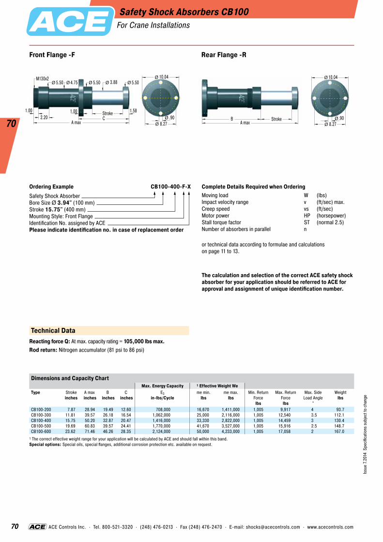
70
70
Issu
e 7.
2014
Spe
cific
atio
ns s
ubje
ct to
cha
nge
ACE Controls Inc. · Tel. 800-521-3320 · (248) 476-0213 · Fax (248) 476-2470 · E-mail: [email protected] · www.acecontrols.com
Safety Shock Absorbers CB100For Crane Installations
3.88
A max
1.58
5.50M130x2
4.75 5.50 5.50
StrokeC
1.002.20
1.00
Ø Ø Ø Ø Ø10.04
8.27.90Ø
Ø
Ø
Front Flange -F
A maxStrokeB
10.04
8.27.90Ø
Ø
Ø
Rear Flange -R
The calculation and selection of the correct ACE safety shock absorber for your application should be referred to ACE for approval and assignment of unique identification number.
Ordering Example CB100-400-F-XSafety Shock AbsorberBore Size Ø 3.94" (100 mm)Stroke 15.75" (400 mm)Mounting Style: Front FlangeIdentification No. assigned by ACEPlease indicate identification no. in case of replacement order
Complete Details Required when OrderingMoving load W (lbs)Impact velocity range v (ft/sec) max.Creep speed vs (ft/sec)Motor power HP (horsepower)Stall torque factor ST (normal 2.5)Number of absorbers in parallel n
or technical data according to formulae and calculations on page 11 to 13.
Technical DataReacting force Q: At max. capacity rating = 105,000 lbs max.Rod return: Nitrogen accumulator (81 psi to 86 psi)
Dimensions and Capacity ChartMax. Energy Capacity 1 Effective Weight We
Type
Stroke inches
A max inches
B inches
C inches
E3 in-lbs/Cycle
me min. lbs
me max. lbs
Min. Return Force lbs
Max. Return Force lbs
Max. Side Load Angle
°
Weight lbs
CB100-200 7.87 28.94 19.49 12.60 708,000 16,670 1,411,000 1,005 9,917 4 93.7CB100-300 11.81 39.57 26.18 16.54 1,062,000 25,000 2,116,000 1,005 12,540 3.5 112.1CB100-400 15.75 50.20 32.87 20.47 1,416,000 33,330 2,822,000 1,005 14,459 3 130.4CB100-500 19.69 60.83 39.57 24.41 1,770,000 41,670 3,527,000 1,005 15,916 2.5 148.7CB100-600 23.62 71.46 46.26 28.35 2,124,000 50,000 4,233,000 1,005 17,058 2 167.0
1 The correct effective weight range for your application will be calculated by ACE and should fall within this band. Special options: Special oils, special flanges, additional corrosion protection etc. available on request.

71
71
Issu
e 7.
2014
Spe
cific
atio
ns s
ubje
ct to
cha
nge
ACE Controls Inc. · Tel. 800-521-3320 · (248) 476-0213 · Fax (248) 476-2470 · E-mail: [email protected] · www.acecontrols.com
Safety Shock Absorbers CB160For Crane Installations
6.00
A max
2.36
9.00M210x2
7.00 9.00 9.00
StrokeC
1.504.06
1.50
Ø Ø Ø Ø Ø13.75
11.621.06Ø
Ø
Ø
6x60°
Front Flange -F
13.75
11.621.06Ø
Ø
Ø
6x60°A max
StrokeB
Rear Flange -R
The calculation and selection of the correct ACE safety shock absorber for your application should be referred to ACE for approval and assignment of unique identification number.
Ordering Example CB160-400-F-XSafety Shock AbsorberBore Size Ø 6.30" (160 mm)Stroke 15.75" (400 mm)Mounting Style: Front FlangeIdentification No. assigned by ACEPlease indicate identification no. in case of replacement order
Complete Details Required when OrderingMoving load W (lbs)Impact velocity range v (ft/sec) max.Creep speed vs (ft/sec)Motor power HP (horsepower)Stall torque factor ST (normal 2.5)Number of absorbers in parallel n
or technical data according to formulae and calculations on page 11 to 13.
Technical DataReacting force Q: At max. capacity rating = 157,000 lbs max.Rod return: Nitrogen accumulator (81 psi to 86 psi)
Dimensions and Capacity ChartMax. Energy Capacity 1 Effective Weight We
Type
Stroke inches
A max inches
B inches
C inches
E3 in-lbs/Cycle
me min. lbs
me max. lbs
Min. Return Force lbs
Max. Return Force lbs
Max. Side Load Angle
°
Weight lbs
CB160-400 15.75 55.12 37.01 23.62 2,124,000 50,000 4,233,000 2,455 15,845 4 340.9CB160-600 23.62 78.74 52.76 31.50 3,186,000 75,000 6,349,000 2,455 15,857 3 414.4CB160-800 31.50 102.36 68.50 39.37 4,248,000 100,000 8,466,000 2,455 15,869 2 487.9
1 The correct effective weight range for your application will be calculated by ACE and should fall within this band. Special options: Special oils, special flanges, additional corrosion protection etc. available on request.

72
72
Issu
e 7.
2014
Spe
cific
atio
ns s
ubje
ct to
cha
nge
Safety Shock Absorbers EB63 to EB160
Function: During the braking process, the piston rod is pushed in. The hydraulic oil in front of the piston is simultaneously expelled through all orifice openings. The number of orifice openings in effect reduces in proportion to the stroke movement. The retraction speed is reduced. The back-pressure created in front of the piston, and therefore the counter-force (Q), remain constant during the complete stroke. The oil volume displaced by the piston rod is compensated for by the separating piston. The piston rod is extended again by the spring assembly in the piston tube.Impact velocity range: 1.6 to 15 ft/secMaterial: Steel body with black oxide finish. Piston rod hard chrome plated.Operating temperature range: 10 °F to 150 °FInitial fill pressure: governs the rod return force.In creep speed: The shock absorber can be pushed through its stroke.
The newly-developed EB series offers all the advantages of the CB series such as inter- nal system seals, generously dimensioned piston rod bearings and maximum energy absorption for emergency braking. The internal spring assembly in the piston tube ensures reliable extension of the piston rod following compression. Because of the extension via the spring assembly, the extension forces are reduced significantly in comparison to the CB series. The performance curve and damp- ing characteristics of the maintenance-free and ready-to-install EB safety shock absorber, like all ACE safety shock absorbers, is individually tailored to the relevant application.
Piston Tube
Gas Accumulator
Rod Wiper
Hydraulic Oil
Separator Piston
Seals
Piston
Metering Orifices
Mounting Flange
Positive Stop
Spring Package
Pressure Chamber
Rod Button

73
73
Issu
e 7.
2014
Spe
cific
atio
ns s
ubje
ct to
cha
nge
ACE Controls Inc. · Tel. 800-521-3320 · (248) 476-0213 · Fax (248) 476-2470 · E-mail: [email protected] · www.acecontrols.com
Safety Shock Absorbers EB63
2.38
A max
1.26
3.75M90x2 3.12 3.75 3.75
StrokeC
.751.61
.75
Ø Ø Ø Ø Ø6.50
5.31.71Ø
Ø
Ø
Front Flange -F
A maxStrokeB
6.50
5.31.71Ø
Ø
Ø
Rear Flange -R
The calculation and selection of the correct ACE safety shock absorber for your application should be referred to ACE for approval and assignment of unique identification number.
Ordering Example EB63-400-F-XSafety Shock AbsorberBore Size Ø 2.48" (63 mm)Stroke 15.75" (400 mm)Mounting Style: Front FlangeIdentification No. assigned by ACEPlease indicate identification no. in case of replacement order
Complete Details Required when OrderingMoving load W (lbs)Impact velocity range v (ft/sec) max.Creep speed vs (ft/sec)Motor power HP (horsepower)Stall torque factor ST (normal 2.5)Number of absorbers in parallel n
or technical data according to formulae and calculations on page 11 to 13.
Technical DataReacting force Q: At max. capacity rating = 42,000 lbs max.Rod return: Nitrogen accumulator (8 psi to 15 psi) combined with return spring
Dimensions and Capacity ChartMax. Energy Capacity 1 Effective Weight We
Type
Stroke inches
A max inches
B inches
C inches
E3 in-lbs/Cycle
me min. lbs
me max. lbs
Min. Return Force lbs
Max. Return Force lbs
Max. Side Load Angle
°
Weight lbs
EB63-100 3.94 16.54 11.34 7.56 141,600 3,330 282,000 157 1,562 3.5 30.2EB63-200 7.87 27.56 18.43 11.50 283,200 6,660 564,000 172 2,084 3 36.8EB63-300 11.81 38.58 25.51 15.43 424,800 10,010 847,000 187 2,372 2.5 48.1EB63-400 15.75 49.61 32.60 19.37 566,400 13,340 1,129,000 136 2,496 2 56.9EB63-500 19.69 60.63 39.69 23.31 708,000 16,670 1,411,000 151 2,691 1.5 65.7
1 The correct effective weight range for your application will be calculated by ACE and should fall within this band. Special options: Special oils, special flanges, additional corrosion protection etc. available on request.

74
74
Issu
e 7.
2014
Spe
cific
atio
ns s
ubje
ct to
cha
nge
ACE Controls Inc. · Tel. 800-521-3320 · (248) 476-0213 · Fax (248) 476-2470 · E-mail: [email protected] · www.acecontrols.com
Safety Shock Absorbers EB100
3.88
A max
1.58
5.50M130x2
4.75 5.50 5.50
StrokeC
1.002.20
1.00
Ø Ø Ø Ø Ø10.04
8.27.90Ø
Ø
Ø
Front Flange -F
A maxStrokeB
10.04
8.27.90Ø
Ø
Ø
Rear Flange -R
The calculation and selection of the correct ACE safety shock absorber for your application should be referred to ACE for approval and assignment of unique identification number.
Ordering Example EB100-400-F-XSafety Shock AbsorberBore Size Ø 3.94" (100 mm)Stroke 15.75" (400 mm)Mounting Style: Front FlangeIdentification No. assigned by ACEPlease indicate identification no. in case of replacement order
Complete Details Required when OrderingMoving load W (lbs)Impact velocity range v (ft/sec) max.Creep speed vs (ft/sec)Motor power HP (horsepower)Stall torque factor ST (normal 2.5)Number of absorbers in parallel n
or technical data according to formulae and calculations on page 11 to 13.
Technical DataReacting force Q: At max. capacity rating = 105,000 lbs max.Rod return: Nitrogen accumulator (8 psi to 15 psi) combined with return spring
Dimensions and Capacity ChartMax. Energy Capacity 1 Effective Weight We
Type
Stroke inches
A max inches
B inches
C inches
E3 in-lbs/Cycle
me min. lbs
me max. lbs
Min. Return Force lbs
Max. Return Force lbs
Max. Side Load Angle
°
Weight lbs
EB100-200 7.87 28.94 19.49 12.60 708,000 16,670 1,411,000 271 1,999 4 93.7EB100-300 11.81 39.57 26.18 16.54 1,062,000 25,000 2,116,000 213 3,163 3.5 112EB100-400 15.75 50.20 32.87 20.47 1,416,000 33,330 2,822,000 267 4,089 3 130.3EB100-500 19.69 60.83 39.57 24.41 1,770,000 41,670 3,527,000 209 4,686 2.5 151EB100-600 23.62 71.46 46.26 28.35 2,124,000 50,000 4,233,000 263 5,248 2 169.3
1 The correct effective weight range for your application will be calculated by ACE and should fall within this band. Special options: Special oils, special flanges, additional corrosion protection etc. available on request.

75
75
Issu
e 7.
2014
Spe
cific
atio
ns s
ubje
ct to
cha
nge
ACE Controls Inc. · Tel. 800-521-3320 · (248) 476-0213 · Fax (248) 476-2470 · E-mail: [email protected] · www.acecontrols.com
Safety Shock Absorbers EB160
6.00
A max
2.36
9.00M210x2
7.00 9.00 9.00
StrokeC
1.504.06
1.50
Ø Ø Ø Ø Ø13.75
11.621.06Ø
Ø
Ø
6x60°
Front Flange -F
13.75
11.621.06Ø
Ø
Ø
6x60°A max
StrokeB
Rear Flange -R
The calculation and selection of the correct ACE safety shock absorber for your application should be referred to ACE for approval and assignment of unique identification number.
Ordering Example EB160-400-F-XSafety Shock AbsorberBore Size Ø 6.30" (160 mm)Stroke 15.75" (400 mm)Mounting Style: Front FlangeIdentification No. assigned by ACEPlease indicate identification no. in case of replacement order
Complete Details Required when OrderingMoving load W (lbs)Impact velocity range v (ft/sec) max.Creep speed vs (ft/sec)Motor power HP (horsepower)Stall torque factor ST (normal 2.5)Number of absorbers in parallel n
or technical data according to formulae and calculations on page 11 to 13.
Technical DataReacting force Q: At max. capacity rating = 157,000 lbs max.Rod return: Nitrogen accumulator (8 psi to 15 psi) combined with return spring
Dimensions and Capacity ChartMax. Energy Capacity 1 Effective Weight We
Type
Stroke inches
A max inches
B inches
C inches
E3 in-lbs/Cycle
me min. lbs
me max. lbs
Min. Return Force lbs
Max. Return Force lbs
Max. Side Load Angle
°
Weight lbs
EB160-400 15.75 55.12 37.01 23.62 2,124,000 50,000 4,233,000 421 4,071 4 343.0EB160-600 23.62 78.74 52.76 31.50 3,186,000 75,000 6,349,000 474 4,225 3 416.7EB160-800 31.50 102.36 68.50 39.37 4,248,000 100,000 8,466,000 535 4,380 2 490.1
1 The correct effective weight range for your application will be calculated by ACE and should fall within this band. Special options: Special oils, special flanges, additional corrosion protection etc. available on request.

76
76
Issu
e 7.
2014
Spe
cific
atio
ns s
ubje
ct to
cha
nge
ACE Controls Inc. · Tel. 800-521-3320 · (248) 476-0213 · Fax (248) 476-2470 · E-mail: [email protected] · www.acecontrols.com
Permitted UseACE safety shock absorbers are machine elements to brake moving masses in a defined end position in emergency stop situations for axial forces. The safety shock absorbers are not designed for regular operational usage.
Calculation of safety shock absorbersThe calculation of safety shock absorbers should generally be performed or checked by ACE.
Deceleration PropertiesThe orifice sizing and drill pattern in the pressure chamber are individu-ally designed for each safety shock absorber. The respective absorption characteristic is optimized corresponding to the maximum mass that occurs in the emergency stop and the impact speed. Correspondingly, each safety shock absorber is given an individual identification number.
Model CodeFor types SCS33 to 64, the individual five-digit identification numbers can be taken from the last digits of the shock absorber model code shown on the label. Example: SCS33-50-1XXXX. For type series SCS38 to SCS63, CB63 to CB160 and EB63 to EB160, the identification number is a five digit number. Example: SCS38-100-F-XXXXX. In addition to the model code, the label also shows the authorised maximum impact velocity and maximum authorized impact mass for the unit.
MountingTo mount the shock absorber, we recommend the use of original ACE mounting accessories shown in catalogue. The mounting of each shock absorber must be exactly positioned so that the reaction force (Q) can be adequately transmitted into the mounting structure. ACE recom-mends installation via the front flange -F mounting style that ensures the maximum protection against buckling. The damper must be mounted so that the moving loads are decelerated with the least possible side loading to the piston rod. The maximum permissable side load angles are detailed in our current catalogue.The entire stroke length must be used for deceleration because only using part of the stroke can lead to overstressing and damage to the unit.
Mounting style front flange -F
Environmental RequirementsThe permissible temperature range for each shock absorber type can be found in our current catalogue. CAUTION: Usage outside the specified temperature range can lead to premature breakdown and damage of of the shock absorbers which can then result in severe system damage or machine failures. Trouble free operation outdoors or in damp environments is only war- ranted if the dampers are coated with a specific corrosion protection finish.
Initial Start-Up ChecksFirst impacts on the shock absorber should only be tried after correctly mounting and with reduced impact speeds and – if possible – with reduced load. Differences between calculated and actual operating data can then be detected early on, and damage to your system can be avoided. If the shock absorbers were selected on calculated data that does not correspond to the maximum possible loading (i.e. selection based on drive power being switched off or at reduced impact speed) then these restricted impact conditions must not be exceeded during initial testing or subsequent use of the system. Otherwise you risk damaging the shock absorbers and/or your machine by overstressing materials. After the initial trial check that the piston rod fully extends again and that there are no signs of oil leakage. Also check that the mounting hardware is still securely tightened. You should be fully assured that no damage has occurred to the piston rod, the body, or the mounting hardware.
Fixed Mechanical StopSafety shock absorbers do not need an external stop as a stroke limiter. The stroke of the safety absorber is limited by the stop of the impact head on the shock absorber. For types SCS33 to SCS64, the fixed stop point is achieved with the integrated stop collar.
What Needs to be Checked after a Full Load Impact?Safety shock absorbers that were originally checked only at reduced speed or load need to be checked again after a full load impact (i.e. emergency use) has occurred. Check that the piston rod fully extends to its full out position, that there are no signs of oil leakage and that the mounting hardware is still securely fixed. You should be fully assured that no damage has occurred to the piston rod, the body, or the mount- ing hardware. If no damage has occurred, the safety shock absorber can be put back into normal operation (see initial start-up).
MaintenanceSafety shock absorbers are sealed systems and do not need special maintenance. Safety shock absorbers that are not used regularly (i.e. that are intended for emergency stop systems) should be checked within the normal time frame for safety checks, but at least once a year. At this time special attention must be paid to checking that the piston rod resets to its fully extended position, that there is no oil leakage and that the mounting brackets are still secure and undamaged. The piston rod must not show any signs of damage. Safety shock absorbers that are in use regularly should be checked every three months.
Repair NoticeIf any damage to the shock absorber is detected or if there are any doubts as to the proper functioning of the unit please send the unit for service to ACE. Alternatively contact your local ACE office for further advice.
Detailed information on the above listed points can be taken from the corresponding operating and assembly instructions.
Safety Shock Absorber SCS Safety Shock Absorber CB
Safety Shock AbsorbersGeneral Instructions
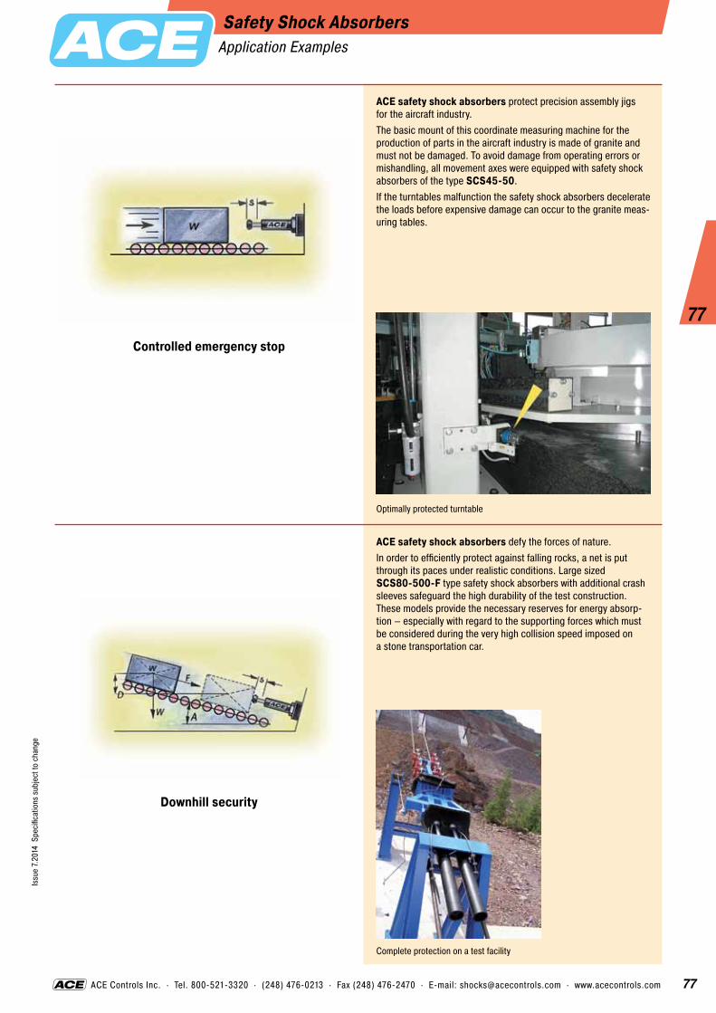
77
77
Issu
e 7.
2014
Spe
cific
atio
ns s
ubje
ct to
cha
nge
ACE Controls Inc. · Tel. 800-521-3320 · (248) 476-0213 · Fax (248) 476-2470 · E-mail: [email protected] · www.acecontrols.com
Safety Shock AbsorbersApplication Examples
Controlled emergency stop
Downhill security
ACE safety shock absorbers protect precision assembly jigs for the aircraft industry.The basic mount of this coordinate measuring machine for the production of parts in the aircraft industry is made of granite and must not be damaged. To avoid damage from operating errors or mishandling, all movement axes were equipped with safety shock absorbers of the type SCS45-50. If the turntables malfunction the safety shock absorbers decelerate the loads before expensive damage can occur to the granite meas- uring tables.
ACE safety shock absorbers defy the forces of nature.In order to efficiently protect against falling rocks, a net is put through its paces under realistic conditions. Large sized SCS80-500-F type safety shock absorbers with additional crash sleeves safeguard the high durability of the test construction. These models provide the necessary reserves for energy absorp- tion – especially with regard to the supporting forces which must be considered during the very high collision speed imposed on a stone transportation car.
Optimally protected turntable
Complete protection on a test facility

78
Issu
e 7.
2014
Spe
cific
atio
ns s
ubje
ct to
cha
nge
78
One-PieceProfile Body
Mounting Screw
TUBUS-Series Type TA BumperAxial Damping
Impact velocity range: Up to max. 16.4 ft/secEnvironment: Resistant to oil, grease, seawater and to microbe or chemical attack. Excellent UV and ozone resistance. Material does not absorb water or swell.Mounting: In any positionDynamic force range: 196 lbs to 20,233 lbsOperating temperature range: -40 °F to 120 °F Energy absorption: 58 % to 73 %Material hardness rating: Shore 55DMax. torque: M3: 0.74 ft-lbs M4: 1.25 ft-lbs M5: 1.70 ft-lbs (DIN912) 4.43 ft-lbs (Shouldered screw) M6: 7.38 ft-lbs M8: 14.75 ft-lbs M12: 36.88 ft-lbs M16: 88.51 ft-lbsNote: Mounting screw should additionally be secured with Loctite.On request: Special strokes, -characteristics, -spring rates, -sizes and -materials.
The bumper type TA from the innovative ACE TUBUS series is a maintenance-free, self-contained damping product made from a special Co-Polyester Elastomer. As a result of the degressive damping characteristic it pro- vides a high energy absorption at the begin- ning of its stroke. The excellent temperature characteristic of the material provides consistent damping performance over a tem- perature of -40 °F to 120 °F. The low installed weight, the economic price and the long operating life of up to 1 million cycles make this an attractive alternative to hydraulic end position damping, if the moving mass does not have to stop in an exact datum position and it is not necessary to absorb 100 % of the incoming energy. The space-saving package size ranges from Ø 0.47" up to Ø 4.57" and is very simply and quickly installed with the supplied specially stepped mounting screw. The TA series have been specially developed to provide maximum energy capacity in the minimum mounting space in the capacity range from 17.7 in-lbs up to 26,119 in-lbs.
Life expectancy is extremely high; up to twenty times longer than urethane dampers, up to ten times longer than rubber bumpers and up to five times longer than steel springs.
Calculation and selection to be approved by ACE. For applications with preloading and increased temperatures please consult ACE.

79
Issu
e 7.
2014
Spe
cific
atio
ns s
ubje
ct to
cha
nge
79
ACE Controls Inc. · Tel. 800-521-3320 · (248) 476-0213 · Fax (248) 476-2470 · E-mail: [email protected] · www.acecontrols.com
TUBUS-Series Type TA BumperAxial Damping
d1 d2D
L1 L2
Max.Stroke
M
The calculation and selection of the required bumper should be carried out or be approved by ACE.
Ordering Example TA37-16TUBUS AxialOuter-Ø 1.46" (37 mm)Stroke 0.63" (16 mm)
Characteristics of Type TA37-16 Energy-Stroke Characteristic (dynamic)(with impact velocity over 0.5 m/s)
Stroke (mm)
Ener
gy (N
m)
Force-Stroke Characteristic (dynamic)(with impact velocity over 0.5 m/s)
Stroke (mm)
Forc
e (N
)
With the aid of the characteristic curves above you can estimate the proportion of the total energy that will be absorbed.Example: With impact energy of 50 Nm the Energy-Stroke diagram shows that a stroke of about 8.8 mm is needed. On the Force-Stroke diagram you can estimate the proportion of absorbed energy to rebound energy at this stroke length.Dynamic (v > 0.5 m/s) and static (v ≤ 0.5 m/s) characteristics of all types are available on request.
9000
7500
6000
4500
3000
1500
0 1 2 3 4 5 6 7 8 9 10
70
60
50
40
30
20
10
0 1 2 3 4 5 6 7 8 9 10
absorbed energy
rebound stroke energy
F in
F back
Dimensions and Capacity ChartType
1 E3 in-lbs/Cycle
2 E3 in-lbs/Cycle
Max. Stroke inches
D inches
L1 inches
M
L2 inches
d1 inches
d2 inches
Weight lbs
TA12-5 17.7 26.6 0.20 0.47 0.12 M3 0.43 0.59 0.43 0.002 TA17-7 53.1 79.7 0.28 0.67 0.16 M4 0.63 0.87 0.59 0.009 TA21-9 88.5 142 0.35 0.83 0.20 M5 0.71 1.02 0.71 0.015 TA22-10 102 186 0.39 0.87 0.24 M6 0.75 1.06 0.75 0.018 TA28-12 257 407 0.47 1.10 0.24 M6 1.02 1.42 0.98 0.035 TA34-14 425 770 0.55 1.34 0.24 M6 1.18 1.69 1.18 0.053 TA37-16 575 991 0.63 1.46 0.24 M6 1.30 1.89 1.30 0.068 TA40-16 726 1,151 0.63 1.57 0.31 M8 1.38 1.97 1.34 0.088 TA43-18 991 1,460 0.71 1.69 0.31 M8 1.50 2.17 1.50 0.112 TA47-20 1,239 1,531 0.79 1.85 0.47 M12 1.61 2.36 1.61 0.176 TA50-22 1,505 1,974 0.87 1.97 0.47 M12 1.77 2.52 1.73 0.187 TA54-22 1,779 2,956 0.87 2.13 0.47 M12 1.85 2.68 1.85 0.220 TA57-24 2,142 2,673 0.94 2.24 0.47 M12 2.01 2.87 1.97 0.256 TA62-25 2,691 3,195 0.98 2.44 0.47 M12 2.13 3.07 2.09 0.291 TA65-27 3,310 4,142 1.06 2.56 0.47 M12 2.28 3.23 2.24 0.337 TA70-29 3,726 4,638 1.14 2.76 0.47 M12 2.40 3.39 2.36 0.384 TA72-31 4,266 4,948 1.22 2.83 0.63 M16 2.56 3.58 2.48 0.567 TA80-32 5,045 7,355 1.26 3.15 0.63 M16 2.72 3.94 2.72 0.688 TA82-35 6,045 8,152 1.38 3.23 0.63 M16 2.91 4.13 2.83 0.774 TA85-36 7,054 9,231 1.42 3.35 0.63 M16 2.99 4.33 2.95 0.862 TA90-38 8,267 11,055 1.50 3.54 0.63 M16 3.15 4.49 3.07 0.913 TA98-40 10,152 13,763 1.57 3.86 0.63 M16 3.39 4.84 3.35 1.131 TA116-48 17,825 26,119 1.89 4.57 0.63 M16 3.98 5.75 3.86 1.770
1 Max. energy capacity per cycle for continous use. 2 Energy capacity per cycle for emergency use.

80
Issu
e 7.
2014
Spe
cific
atio
ns s
ubje
ct to
cha
nge
80
One-PieceProfile Body
Mounting Screw
TUBUS-Series Type TS BumperAxial Soft Damping
The bumper type TS from the innovative ACE TUBUS series is a maintenance-free, self-contained damping product made from a special Co-Polyester Elastomer. As a result of the almost linear damping characteristic it provides a very smooth energy absorption with minimum reaction loads on the machine. The excellent temperature characteristic of the material provides consistent damping perform- ance over a temperature of -40 °F to 120 °F. The low installed weight, the economic price and the long operating life of up to 1 million cycles make this an attractive alternative to hydraulic end position damping, if the moving mass does not have to stop in an exact datum position and it is not necessary to absorb 100 % of the incoming energy. The space saving package size ranges from Ø 0.55" up to Ø 4.21" and is very simply and quickly installed with the supplied specially stepped mounting screw. The TS series have been specially developed to provide maximum energy capacity in the minimum mounting space in the capacity range from 17.7 in-lbs up to 8,550 in-lbs.
Life expectancy is extremely high; up to twenty times longer than urethane dampers, up to ten times longer than rubber bumpers and up to five times longer than steel springs.
Calculation and selection to be approved by ACE. For applications with preloading and increased temperatures please consult ACE.
Impact velocity range: Up to max. 16.4 ft/secEnvironment: Resistant to oil, grease, seawater and to microbe or chemical attack. Excellent UV and ozone resistance. Material does not absorb water or swell.Mounting: In any positionDynamic force range: 120 lbs to 5,283 lbsOperating temperature range: -40 °F to 120 °F Energy absorption: 35 % to 64 %Material hardness rating: Shore 40DMax. torque: M4: 1.25 ft-lbs M5: 1.70 ft-lbs (DIN912) 4.43 ft-lbs (Shouldered screw) M6: 7.38 ft-lbs M12: 36.88 ft-lbs M16: 88.51 ft-lbsNote: Mounting screw should additionally be secured with Loctite.On request: Special strokes, -characteristics, -spring rates, -sizes and -materials.

81
Issu
e 7.
2014
Spe
cific
atio
ns s
ubje
ct to
cha
nge
81
ACE Controls Inc. · Tel. 800-521-3320 · (248) 476-0213 · Fax (248) 476-2470 · E-mail: [email protected] · www.acecontrols.com
TUBUS-Series Type TS BumperAxial Soft Damping
d1 d2D
L1 L2
Max.Stroke
M
The calculation and selection of the required bumper should be carried out or be approved by ACE.
Ordering Example TS44-23TUBUS Axial SoftOuter-Ø 1.73" (44 mm)Stroke 0.91" (23 mm)
Characteristics of Type TS44-23
6000
5000
4000
3000
2000
1000
0 3 6 9 12 15 18
Energy-Stroke Characteristic (dynamic)(with impact velocity over 0.5 m/s)
Stroke (mm)
Ener
gy (N
m)
Force-Stroke Characteristic (dynamic)(with impact velocity over 0.5 m/s)
Stroke (mm)
Forc
e (N
)
With the aid of the characteristic curves above you can estimate the proportion of the total energy that will be absorbed.Example: With impact energy of 50 Nm the Energy-Stroke diagram shows that a stroke of about 14 mm is needed. On the Force-Stroke diagram you can estimate the proportion of absorbed energy to rebound energy at this stroke length.Dynamic (v > 0.5 m/s) and static (v ≤ 0.5 m/s) characteristics of all types are available on request.
absorbed energy
rebound stroke energy
F in
F back
70
60
50
40
30
20
10
0 3 6 9 12 15 18
Dimensions and Capacity ChartType
1 E3 in-lbs/Cycle
2 E3 in-lbs/Cycle
Max. Stroke inches
D inches
L1 inches
M
L2 inches
d1 inches
d2 inches
Weight lbs
TS14-7 17.7 26.6 0.28 0.55 0.16 M4 0.59 0.75 0.51 0.007 TS18-9 35.4 53.1 0.35 0.71 0.20 M5 0.71 0.94 0.63 0.013 TS20-10 53.1 62.0 0.39 0.79 0.24 M6 0.83 1.06 0.75 0.018 TS26-15 102 133 0.59 1.02 0.24 M6 1.10 1.46 0.98 0.033 TS32-16 204 230 0.63 1.26 0.24 M6 1.26 1.73 1.18 0.046 TS35-19 266 319 0.75 1.38 0.24 M6 1.42 1.89 1.30 0.062 TS40-19 301 372 0.75 1.57 0.24 M6 1.50 2.01 1.34 0.068 TS41-21 425 558 0.83 1.61 0.47 M12 1.61 2.17 1.50 0.112 TS44-23 558 637 0.91 1.73 0.47 M12 1.77 2.36 1.57 0.159 TS48-25 717 805 0.98 1.89 0.47 M12 1.93 2.52 1.73 0.190 TS51-27 814 1,009 1.06 2.01 0.47 M12 2.05 2.72 1.85 0.225 TS54-29 1,080 1,398 1.14 2.13 0.47 M12 2.17 2.87 1.97 0.256 TS58-30 1,319 1,363 1.18 2.28 0.47 M12 2.32 3.07 2.09 0.291 TS61-32 1,443 1,496 1.26 2.40 0.63 M16 2.44 3.27 2.20 0.448 TS64-34 1,841 2,248 1.34 2.52 0.63 M16 2.60 3.43 2.36 0.514 TS68-36 2,009 2,407 1.42 2.68 0.63 M16 2.72 3.62 2.48 0.547 TS75-39 2,576 3,611 1.54 2.95 0.63 M16 2.95 3.98 2.72 0.664 TS78-40 3,115 4,062 1.57 3.07 0.63 M16 3.11 4.13 2.83 0.747 TS82-44 3,708 5,487 1.73 3.23 0.63 M16 3.31 4.33 2.95 0.763 TS84-43 4,204 5,620 1.69 3.31 0.63 M16 3.35 4.53 3.07 0.886 TS90-47 5,133 6,886 1.85 3.54 0.63 M16 3.62 4.88 3.31 1.080 TS107-56 7,983 8,550 2.20 4.21 0.63 M16 4.33 5.79 3.94 1.616
1 Max. energy capacity per cycle for continous use. 2 Energy capacity per cycle for emergency use.

82
Issu
e 7.
2014
Spe
cific
atio
ns s
ubje
ct to
cha
nge
82
One-PieceProfile Body
Mounting Screw
TUBUS-Series Type TR BumperRadial Damping
The bumper type TR from the innovative ACE TUBUS series is a maintenance-free, self-contained damping product made from a special Co-Polyester Elastomer. The radial deformation of the TR series provides a very long and soft deceleration with a progressive energy absorption towards the end of stroke. The excellent temperature characteristic ofthe material provides consistent damping performance over a temperature of -40 °F to 120 °F. The low installed weight, the eco- nomic price and the long operating life of up to 1 million cycles make this an attractive alter- native to hydraulic end position damping, if the moving mass does not have to stop in an exact datum position and it is not necessary to absorb 100 % of the incoming energy. The space saving package size ranges from Ø 1.14" up to Ø 3.94" and is very simply and quickly installed with the supplied special stepped mounting screw. The TR series have been spe- cially developed to provide maximum stroke in the minimum mounting space in the ca- pacity range from 10.6 in-lbs up to 1,292 in-lbs.
Life expectancy is extremely high; up to twenty times longer than urethane dampers, up to ten times longer than rubber bumpers and up to five times longer than steel springs.
Calculation and selection to be approved by ACE. For applications with preloading and increased temperatures please consult ACE.
Impact velocity range: Up to max. 16.4 ft/secEnvironment: Resistant to oil, grease, seawater and to microbe or chemical attack. Excellent UV and ozone resistance. Material does not absorb water or swell.Mounting: In any positionDynamic force range: 49 lbs to 1,686 lbsOperating temperature range: -40 °F to 120 °F Energy absorption: 25 % to 45 %Material hardness rating: Shore 40DMax. torque: M5: 4.43 ft-lbs M6: 7.38 ft-lbs M8: 14.75 ft-lbsNote: Mounting screw should additionally be secured with Loctite.On request: Special strokes, -characteristics, -spring rates, -sizes and -materials.
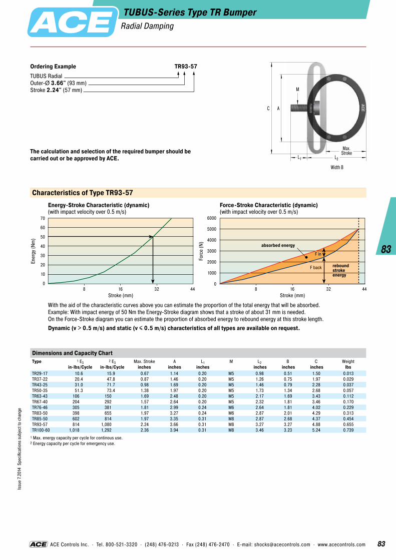
83
Issu
e 7.
2014
Spe
cific
atio
ns s
ubje
ct to
cha
nge
83
ACE Controls Inc. · Tel. 800-521-3320 · (248) 476-0213 · Fax (248) 476-2470 · E-mail: [email protected] · www.acecontrols.com
TUBUS-Series Type TR BumperRadial Damping
A
L1 L2
Max.Stroke
M
C
Width B
The calculation and selection of the required bumper should be carried out or be approved by ACE.
Ordering Example TR93-57TUBUS RadialOuter-Ø 3.66" (93 mm)Stroke 2.24" (57 mm)
Characteristics of Type TR93-57
6000
5000
4000
3000
2000
1000
0 8 16 32 44
Energy-Stroke Characteristic (dynamic)(with impact velocity over 0.5 m/s)
Stroke (mm)
Ener
gy (N
m)
Force-Stroke Characteristic (dynamic)(with impact velocity over 0.5 m/s)
Stroke (mm)
Forc
e (N
)
With the aid of the characteristic curves above you can estimate the proportion of the total energy that will be absorbed.Example: With impact energy of 50 Nm the Energy-Stroke diagram shows that a stroke of about 31 mm is needed. On the Force-Stroke diagram you can estimate the proportion of absorbed energy to rebound energy at this stroke length.Dynamic (v > 0.5 m/s) and static (v ≤ 0.5 m/s) characteristics of all types are available on request.
absorbed energy
rebound stroke energy
F in
F back
70
60
50
40
30
20
10
0 8 16 32 44
Dimensions and Capacity ChartType
1 E3 in-lbs/Cycle
2 E3 in-lbs/Cycle
Max. Stroke inches
A inches
L1 inches
M
L2 inches
B inches
C inches
Weight lbs
TR29-17 10.6 15.9 0.67 1.14 0.20 M5 0.98 0.51 1.50 0.013 TR37-22 20.4 47.8 0.87 1.46 0.20 M5 1.26 0.75 1.97 0.029 TR43-25 31.0 71.7 0.98 1.69 0.20 M5 1.46 0.79 2.28 0.037 TR50-35 51.3 73.4 1.38 1.97 0.20 M5 1.73 1.34 2.68 0.057 TR63-43 106 150 1.69 2.48 0.20 M5 2.17 1.69 3.43 0.112 TR67-40 204 292 1.57 2.64 0.20 M5 2.32 1.81 3.46 0.170 TR76-46 305 381 1.81 2.99 0.24 M6 2.64 1.81 4.02 0.229 TR83-50 398 655 1.97 3.27 0.24 M6 2.87 2.01 4.29 0.313 TR85-50 602 814 1.97 3.35 0.31 M8 2.87 2.68 4.37 0.454 TR93-57 814 1,080 2.24 3.66 0.31 M8 3.27 3.27 4.88 0.655 TR100-60 1,018 1,292 2.36 3.94 0.31 M8 3.46 3.23 5.24 0.739
1 Max. energy capacity per cycle for continous use. 2 Energy capacity per cycle for emergency use.

84
Issu
e 7.
2014
Spe
cific
atio
ns s
ubje
ct to
cha
nge
84
One-PieceProfile Body
Mounting Screw
TUBUS-Series Type TR-H BumperRadial Damping (Hard Version)
Like the standard model TR, the bumper type TR-H is used for radial damping and therefore provides a very long and soft deceleration. The bumpers from the innovative ACE TUBUS series are maintenance-free, self-contained damping products made from a special Co-Polyester Elastomer. With nearly the same dimensions the TUBUS TR-H type provides a much higher energy absorption due to a harder mixture of materials. The TR-H type completes the TUBUS series between the progressive model type TR and the almost linear type TS. This offers an individual and widely graduated range of damp- ing characteristics within the whole TUBUS series. The excellent temperature characteris-tic of the material provides consistent damping performance over a temperature of -40 °F to 120 °F. The low installed weight, the economic price and the long operating life of up to 1 million cycles make this an attractive alternative to hydraulic end position damping, if the moving mass does not have to stop in an exact datum position and it is not necessary to absorb 100 % of the incoming energy. The space saving package size ranges from Ø 1.18" up to Ø 4.02" and is very simply and quickly installed with the supplied special stepped mounting screw. The TR-H series have been specially developed to provide maximum stroke in the minimum mounting space in the capacity range from 23.9 in-lbs up to 3,779 in-lbs.
Life expectancy is extremely high; up to twenty times longer than urethane dampers, up to ten times longer than rubber bumpers and up to five times longer than steel springs.
Calculation and selection to be approved by ACE. For applications with preloading and increased temperatures please consult ACE.
Impact velocity range: Up to max. 16.4 ft/secEnvironment: Resistant to oil, grease, seawater an to microbe or chemical attack. Excellent UV and ozone resistance. Material does not absorb water or swell.Mounting: In any positionDynamic force range: 124 lbs to 4,766 lbsOperating temperature range: -40 °F to 120 °F Energy absorption: 39 % to 62 %Material hardness rating: Shore 55DMax. torque: M5: 4.43 ft-lbs M6: 7.38 ft-lbs M8: 14.75 ft-lbsNote: Mounting screw should additionally be secured with Loctite.On request: Special strokes, -characteristics, -spring rates, -sizes and -materials.

85
Issu
e 7.
2014
Spe
cific
atio
ns s
ubje
ct to
cha
nge
85
ACE Controls Inc. · Tel. 800-521-3320 · (248) 476-0213 · Fax (248) 476-2470 · E-mail: [email protected] · www.acecontrols.com
TUBUS-Series Type TR-H BumperRadial Damping (Hard Version)
A
L1 L2
Max.Stroke
M
C
Width B
The calculation and selection of the required bumper should be carried out or be approved by ACE.
Ordering Example TR95-50HTUBUS Radial Outer-Ø 3.74" (95 mm)Stroke 1.97" (50 mm)Hard Version
Characteristics of Type TR95-50H
12000
10000
8000
6000
4000
2000
0 5 10 15 20 25 30 35 40 45 50
Energy-Stroke Characteristic (dynamic)(with impact velocity over 0.5 m/s)
Stroke (mm)
Ener
gy (N
m)
Force-Stroke Characteristic (dynamic)(with impact velocity over 0.5 m/s)
Stroke (mm)
Forc
e (N
)
With the aid of the characteristic curves above you can estimate the proportion of the total energy that will be absorbed.Example: With impact energy of 50 Nm the Energy-Stroke diagram shows that a stroke of about 25 mm is needed. On the Force-Stroke diagram you can estimate the proportion of absorbed energy to rebound energy at this stroke length.Dynamic (v > 0.5 m/s) and static (v ≤ 0.5 m/s) characteristics of all types are available on request.
absorbed energy
rebound stroke energy
F in
F back
240
210
180
150
120
90
5030
0 5 10 15 20 25 30 35 40 45 50
Dimensions and Capacity ChartType
1 E3 in-lbs/Cycle
2 E3 in-lbs/Cycle
Max. Stroke inches
A inches
L1 inches
M
L2 inches
B inches
C inches
Weight lbs
TR30-15H 23.9 50.5 0.59 1.18 0.20 M5 0.91 0.51 1.50 0.009 TR39-19H 53.1 159 0.75 1.54 0.20 M5 1.18 0.75 1.97 0.024 TR45-23H 77.0 212 0.91 1.77 0.20 M5 1.42 0.79 2.28 0.035 TR52-32H 104 177 1.26 2.05 0.20 M5 1.65 1.34 2.68 0.055 TR64-41H 221 407 1.61 2.52 0.20 M5 2.09 1.69 3.43 0.112 TR68-37H 589 867 1.46 2.68 0.20 M5 2.20 1.81 3.46 0.176 TR79-42H 721 938 1.65 3.11 0.24 M6 2.52 1.81 4.02 0.231 TR86-45H 1,097 1,823 1.77 3.39 0.24 M6 2.72 2.01 4.29 0.322 TR87-46H 1,398 2,310 1.81 3.39 0.31 M8 2.68 2.64 4.37 0.419 TR95-50H 2,018 3,027 1.97 3.74 0.31 M8 3.03 3.23 4.88 0.586 TR102-56H 2,567 3,779 2.20 4.02 0.31 M8 3.31 3.19 5.24 0.703
1 Max. energy capacity per cycle for continous use. 2 Energy capacity per cycle for emergency use.

86
Issu
e 7.
2014
Spe
cific
atio
ns s
ubje
ct to
cha
nge
86
One-PieceProfile Body
Mounting Screw
TUBUS-Series Type TR-L BumperRadial Damping (Long Version)
The radial tube bumper type TR-L from the innovative ACE TUBUS series is a mainte- nance-free, self-contained damping product made from a special Co-Polyester Elastomer. The radial deformation of the TR series provides a very long and soft deceleration with a pro- gressive energy absorption towards the end of stroke. The excellent temperature characteris-tic of the material provides consistent damping performance over a temperature of -40 °F to 120 °F. The tube bumper has been specially developed for applications that require very low reaction forces. The actual force generated depends upon the length of the tube bumper chosen. The TUBUS TR-L type is suitable for a wide range of applications that require protec- tion from shock or impact anywhere along a straight line. Typical applications include mining equipment, dockyard handling equip- ment and on baggage handling and conveyor systems. The TR-L series have been developed to provide maximum stroke in the minimum mounting space in the capacity range from 63.7 in-lbs up to 95,411 in-lbs.
Life expectancy is extremely high; up to twenty times longer than urethane dampers, up to ten times longer than rubber bumpers and up to five times longer than steel springs.
Calculation and selection to be approved by ACE. For applications with preloading and increased temperatures please consult ACE.
Impact velocity range: Up to max. 16.4 ft/secEnvironment: Resistant to oil, grease, seawater an to microbe or chemical attack. Excellent UV and ozone resistance. Material does not absorb water or swell.Capacity rating: For emergency use only (1 cycle) it is possible to exceed the E3 rating by +40 %.Mounting: In any positionDynamic force range: 295 lbs to 48,941 lbsOperating temperature range: -40 °F to 120 °FEnergy absorption: 26 % to 41 %Material hardness rating: Shore 40DMax. torque: M5: 4.43 ft-lbs M8: 14.75 ft-lbs M16: 29.50 ft-lbs (DIN912) 88.51 ft-lbs (Shouldered screw)Note: Mounting screw should additionally be secured with Loctite.On request: Special strokes, -colours, -sizes and -materials.

87
Issu
e 7.
2014
Spe
cific
atio
ns s
ubje
ct to
cha
nge
87
ACE Controls Inc. · Tel. 800-521-3320 · (248) 476-0213 · Fax (248) 476-2470 · E-mail: [email protected] · www.acecontrols.com
TUBUS-Series Type TR-L BumperRadial Damping (Long Version)
DB
A
L1
L2
Max.Stroke
M
C
The calculation and selection of the required bumper should be carried out or be approved by ACE.
Ordering Example TR66-40L-2TUBUS Radial Outer-Ø 2.60" (66 mm)Stroke 1.57" (40 mm)Long VersionLength 2 = 12.01" (305 mm)
Dimensions and Capacity ChartType
1 E3 in-lbs/Cycle
2 E3 in-lbs/Cycle
Max. Stroke inches
A inches
B inches
C inches
D inches
M
L1 inches
L2 inches
Weight lbs
TR29-17L 63.7 96 0.67 1.14 3.15 1.50 1.57 M5 0.20 0.98 0.097 TR43-25L 124 289 0.98 1.69 3.15 2.28 1.57 M5 0.20 1.46 0.159 TR63-43L 194 283 1.69 2.48 3.15 3.43 1.57 M5 0.20 2.17 0.234 TR66-40L-1 903 1,266 1.57 2.60 5.98 3.43 4.02 M8 0.31 2.32 0.060 TR66-40L-2 1,806 2,531 1.57 2.60 12.01 3.43 10.00 M8 0.31 2.32 1.279 TR66-40L-3 2,708 3,788 1.57 2.60 17.99 3.43 15.98 M8 0.31 2.32 1.830 TR66-40L-4 3,611 5,054 1.57 2.60 24.02 3.43 22.01 M8 0.31 2.32 2.491 TR66-40L-5 4,514 6,319 1.57 2.60 30.00 3.43 27.99 M8 0.31 2.32 2.932 TR76-45L-1 1,283 1,797 1.77 2.99 5.98 3.94 4.02 M8 0.31 2.68 0.838 TR76-45L-2 2,567 3,593 1.77 2.99 12.01 3.94 10.00 M8 0.31 2.68 1.534 TR76-45L-3 3,850 5,390 1.77 2.99 17.99 3.94 15.98 M8 0.31 2.68 2.491 TR76-45L-4 5,133 7,187 1.77 2.99 24.02 3.94 22.01 M8 0.31 2.68 3.153 TR76-45L-5 6,417 8,984 1.77 2.99 30.00 3.94 27.99 M8 0.31 2.68 3.924 TR83-48L-1 1,593 2,230 1.89 3.27 5.98 4.17 4.02 M8 0.31 2.87 1.058 TR83-48L-2 3,186 4,461 1.89 3.27 12.01 4.17 10.00 M8 0.31 2.87 2.050 TR83-48L-3 4,779 6,691 1.89 3.27 17.99 4.17 15.98 M8 0.31 2.87 3.042 TR83-48L-4 6,373 8,922 1.89 3.27 24.02 4.17 22.01 M8 0.31 2.87 3.990 TR83-48L-5 7,966 11,152 1.89 3.27 30.00 4.17 27.99 M8 0.31 2.87 4.982 TR99-60L-1 2,390 3,346 2.36 3.90 5.98 5.12 4.02 M16 0.63 3.46 1.742 TR99-60L-2 4,779 6,691 2.36 3.90 12.01 5.12 10.00 M16 0.63 3.46 2.844 TR99-60L-3 7,169 10,037 2.36 3.90 17.99 5.12 15.98 M16 0.63 3.46 4.277 TR99-60L-4 9,559 13,382 2.36 3.90 24.02 5.12 22.01 M16 0.63 3.46 5.600 TR99-60L-5 11,949 16,728 2.36 3.90 30.00 5.12 27.99 M16 0.63 3.46 6.834 TR99-60L-6 14,338 20,073 2.36 3.90 35.98 5.12 34.02 M16 0.63 3.46 8.157 TR99-60L-7 16,728 23,419 2.36 3.90 42.01 5.12 40.00 M16 0.63 3.46 9.480 TR143-86L-1 5,310 7,435 3.39 5.63 5.98 7.52 2.99 M16 0.63 5.00 3.175 TR143-86L-2 10,621 14,869 3.39 5.63 12.01 7.52 7.99 M16 0.63 5.00 6.393 TR143-86L-3 15,931 22,304 3.39 5.63 17.99 7.52 13.98 M16 0.63 5.00 8.554 TR143-86L-4 21,242 29,738 3.39 5.63 24.02 7.52 20.00 M16 0.63 5.00 11.662 TR143-86L-5 26,552 37,173 3.39 5.63 30.00 7.52 25.98 M16 0.63 5.00 14.528 TR143-86L-6 31,863 44,608 3.39 5.63 35.98 7.52 31.97 M16 0.63 5.00 17.394 TR143-86L-7 37,173 52,042 3.39 5.63 42.01 7.52 37.99 M16 0.63 5.00 20.260 TR188-108L-1 9,736 13,630 4.25 7.40 5.98 9.65 2.99 M16 0.63 6.50 5.159 TR188-108L-2 19,472 27,260 4.25 7.40 12.01 9.65 7.99 M16 0.63 6.50 10.229 TR188-108L-3 29,207 40,890 4.25 7.40 17.99 9.65 13.98 M16 0.63 6.50 15.190 TR188-108L-4 38,943 54,521 4.25 7.40 24.02 9.65 20.00 M16 0.63 6.50 20.260 TR188-108L-5 48,679 68,151 4.25 7.40 30.00 9.65 25.98 M16 0.63 6.50 25.111 TR188-108L-6 58,415 81,781 4.25 7.40 35.98 9.65 31.97 M16 0.63 6.50 30.071 TR188-108L-7 68,151 95,411 4.25 7.40 42.01 9.65 37.99 M16 0.63 6.50 35.142
1 Max. energy capacity per cycle for continous use. 2 Energy capacity per cycle for emergency use.

88
Issu
e 7.
2014
Spe
cific
atio
ns s
ubje
ct to
cha
nge
88
One-PieceProfile Body
Mounting Screw
TUBUS-Series Type TR-HD BumperRadial Damping (Heavy Duty Version)
The bumpers type TR-HD from the inno- vative ACE TUBUS series are maintenance free, ready to install damping products manu- factured from a co-polyester elastomer. The TUBUS bumpers are loaded radially just like the basic model TR. Compared to the basic model, however, their solid structural design offers a high level of power and energy absorp- tion within a minimum damping distance. The two different material strengths allow different damping characteristics to be targeted. The slightly biconcave structure also ensures softer force run. The TUBUS TR-HD is suitable for all forms of use, which demand a high level of protection against impact or collision. The high level of power and energy absorption offers a wide range of application, amongst other in agricultural technology and for construction machines e. g. shovels or articulated joints of construction site vehicles. The relevant support power also depends on the material strength of the chosen shock absorber. The TR-HD series was specially developed to absorb a maximum of energy with minimum con- struction height. A stroke of 0.47" to 1.73" easily covers energy absorption within a range of between 2,036 in-lbs and 46,095 in-lbs. The bumper is simply and quickly mounted horizontally as well as vertically with the two supplied screws. The drill distance for fastening can be individually adjusted upon request.
Life expectancy is extremely high; up to twenty times longer than urethane dampers, up to ten times longer than rubber bumpers and up to five times longer than steel springs.
Calculation and selection to be approved by ACE. For applications with preloading and increased temperatures please consult ACE.
Impact velocity range: Up to max. 16.4 ft/secEnvironment: Resistant to oil, grease, seawater an to microbe or chemical attack. Excellent UV and ozone resistance. Material does not absorb water or swell.Capacity rating: For emergency use only (1 cycle) it is possible to exceed the E3 rating by +40 %.Mounting: In any positionDynamic force range: 17,715 lbs to 182,748 lbsOperating temperature range: -40 °F to 120 °FEnergy absorption: 43 % to 76 %Material hardness rating: Shore 40D, Shore 55DMax. torque: M10: 5.16 ft-lbs M12: 8.85 ft-lbsNote: Mounting screw should additionally be secured with Loctite.On request: Special strokes, -characteristics, -spring rates, -sizes and -materials.
NEW
“The latest high capacity version – for maximum force within a minimum
damping distance!”

89
Issu
e 7.
2014
Spe
cific
atio
ns s
ubje
ct to
cha
nge
89
ACE Controls Inc. · Tel. 800-521-3320 · (248) 476-0213 · Fax (248) 476-2470 · E-mail: [email protected] · www.acecontrols.com
TUBUS-Series Type TR-HD BumperRadial Damping (Heavy Duty Version)
DB
A
L1
L2
Max.Stroke
M
C
The calculation and selection of the required bumper should be carried out or be approved by ACE.
Ordering Example TR63-24HDTUBUS RadialOuter-Ø 2.48" (63 mm)Stroke 0.94" (24 mm)Heavy Duty Version
Dimensions and Capacity ChartType
1 E3 in-lbs/Cycle
2 E3 in-lbs/Cycle
F max. static lbs
Max. Stroke inches
A inches
B inches
C inches
D inches
M
L1 inches
L2 inches
Weight lbs
TR42-14HD 3,585 5,018 14,365 0.58 1.64 5.84 2.31 4.02 M10 0.79 1.33 0.375 TR47-12HD 7,585 10,621 33,632 0.48 1.83 5.92 2.28 4.02 M10 0.75 1.23 0.375 TR47-17HD 7,523 10,532 27,449 0.67 1.84 5.90 2.75 4.02 M10 0.94 1.27 0.397 TR52-14HD 14,462 20,250 68,455 0.47 2.14 6.10 2.73 4.02 M10 0.87 1.07 0.397 TR57-21HD 10,568 14,798 23,560 0.86 2.23 5.86 3.12 4.02 M10 0.71 1.87 0.750 TR62-15HD 26,021 36,430 55,078 0.62 2.44 6.02 3.04 4.02 M10 0.63 1.59 0.728 TR62-19HD 26,021 36,430 87,653 0.66 2.94 6.25 3.71 4.02 M10 0.63 1.50 0.794 TR63-24HD 18,241 25,534 43,703 0.97 2.46 6.02 3.61 4.02 M10 0.79 1.79 0.728 TR72-26HD 15,046 21,065 28,056 1.04 2.84 5.88 3.86 4.02 M12 0.91 2.33 1.235 TR79-20HD 24,729 34,624 65,038 0.82 3.12 6.04 3.86 4.02 M12 0.94 2.11 1.257 TR79-31HD 26,331 36,863 50,942 1.17 3.10 6.09 4.42 4.02 M12 0.91 2.21 1.235 TR85-33HD 22,357 31,296 32,845 1.26 3.20 5.89 4.36 4.02 M12 0.91 2.75 1.565 TR89-21HD 39,280 54,990 107,324 0.85 3.50 6.37 4.42 4.02 M12 0.87 1.88 1.235 TR90-37HD 33,456 46,838 54,112 1.48 3.56 6.11 5.04 4.02 M12 0.91 2.71 1.653 TR93-24HD 30,278 42,386 68,005 0.96 3.66 6.10 4.54 4.02 M12 0.91 2.50 1.742 TR97-31HD 68,487 95,880 129,311 1.00 4.11 6.45 5.07 4.02 M12 0.83 2.23 1.764 TR97-35HD 24,968 34,952 34,351 1.50 3.85 5.93 5.16 4.02 M12 0.79 3.30 2.337 TR102-44HD 41,572 58,202 57,214 1.74 4.10 6.15 5.80 4.02 M12 0.87 3.18 2.315 TR105-28HD 49,927 69,894 96,129 1.02 4.12 6.14 4.97 4.02 M12 0.83 2.74 2.205 TR117-30HD 74,851 104,793 143,676 1.09 4.59 6.57 5.61 4.02 M12 0.98 2.48 2.227
1 Max. energy capacity per cycle for continous use. 2 Energy capacity per cycle for emergency use.
Comparison of Damping Characterstics of Type TR-HD
55050045040035030025020015010050
0
Force-Stroke Characteristics (static)
Stroke (mm)
Forc
e (k
N) TR52-14HD
0 5 10 15 20 25 30 35 40
TR47-17HD
TR105-28HD
TR97-35HD
NEW
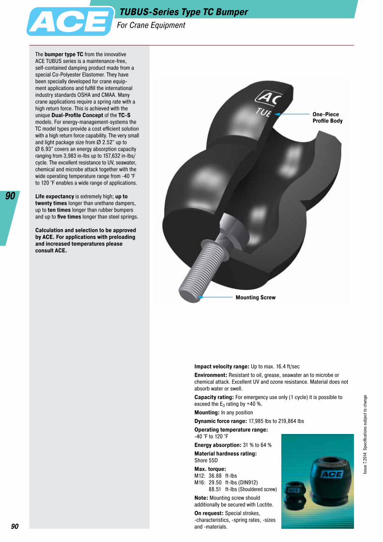
90
Issu
e 7.
2014
Spe
cific
atio
ns s
ubje
ct to
cha
nge
90
One-PieceProfile Body
Mounting Screw
TUBUS-Series Type TC BumperFor Crane Equipment
The bumper type TC from the innovative ACE TUBUS series is a maintenance-free, self-contained damping product made from a special Co-Polyester Elastomer. They have been specially developed for crane equip- ment applications and fulfill the international industry standards OSHA and CMAA. Many crane applications require a spring rate with a high return force. This is achieved with the unique Dual-Profile Concept of the TC-S models. For energy-management-systems the TC model types provide a cost efficient solution with a high return force capability. The very small and light package size from Ø 2.52" up to Ø 6.93" covers an energy absorption capacity ranging from 3,983 in-lbs up to 157,632 in-lbs/cycle. The excellent resistance to UV, seawater, chemical and microbe attack together with the wide operating temperature range from -40 °F to 120 °F enables a wide range of applications.
Life expectancy is extremely high; up to twenty times longer than urethane dampers, up to ten times longer than rubber bumpers and up to five times longer than steel springs.
Calculation and selection to be approved by ACE. For applications with preloading and increased temperatures please consult ACE.
Impact velocity range: Up to max. 16.4 ft/secEnvironment: Resistant to oil, grease, seawater an to microbe or chemical attack. Excellent UV and ozone resistance. Material does not absorb water or swell.Capacity rating: For emergency use only (1 cycle) it is possible to exceed the E3 rating by +40 %.Mounting: In any positionDynamic force range: 17,985 lbs to 219,864 lbsOperating temperature range: -40 °F to 120 °FEnergy absorption: 31 % to 64 %Material hardness rating: Shore 55DMax. torque: M12: 36.88 ft-lbs M16: 29.50 ft-lbs (DIN912) 88.51 ft-lbs (Shouldered screw)Note: Mounting screw should additionally be secured with Loctite.On request: Special strokes, -characteristics, -spring rates, -sizes and -materials.

91
Issu
e 7.
2014
Spe
cific
atio
ns s
ubje
ct to
cha
nge
91
ACE Controls Inc. · Tel. 800-521-3320 · (248) 476-0213 · Fax (248) 476-2470 · E-mail: [email protected] · www.acecontrols.com
TUBUS-Series Type TC BumperFor Crane Equipment
d1 d2D
L1 L2
Max.Stroke
M
d1 d2D
L1 L2
Max.Stroke
M
Model Type TC Model Type TC-S
The calculation and selection of the required bumper should be carried out or be approved by ACE.
Ordering Example TC83-73-STUBUS Crane BufferOuter-Ø 3.27" (83 mm)Stroke 2.87" (73 mm)Model Type Soft
Characteristics of Type TC90-49
450
400
350
300
250
200
150
100
50
0 10 15 20 25 30 35 40
Energy-Stroke Characteristic (dynamic)(with impact velocity over 0.5 m/s)
Stroke (mm)
Ener
gy (N
m)
Force-Stroke Characteristic (dynamic)(with impact velocity over 0.5 m/s)
Stroke (mm)
Forc
e (k
N)
With the aid of the characteristic curves above you can estimate the proportion of the total energy that will be absorbed. Example: With impact energy of 1300 Nm the Energy-Stroke diagram shows that a stroke of about 38 mm is needed. On the Force-Stroke diagram you can estimate the proportion of absorbed energy to rebound energy at this stroke length.Note: With these types the return force towards the end of the stroke is significant and we recommend you try to use a minimum of 90 % of the total stroke available.Dynamic (v > 0.5 m/s) and static (v ≤ 0.5 m/s) characteristics of all types are available on request.
absorbed energy
rebound stroke energy
F in
F back
1800
1500
1200
900
600
300
0 10 15 20 25 30 35 40
Dimensions and Capacity ChartType
1 E3 in-lbs/Cycle
2 E3 in-lbs/Cycle
Max. Stroke inches
D inches
L1 inches
M
L2 inches
d1 inches
d2 inches
Weight lbs
TC64-62-S 3,983 5,576 2.44 2.52 0.47 M12 3.11 3.50 2.05 0.386 TC74-76-S 8,674 12,143 2.99 2.91 0.47 M12 3.78 4.49 2.40 0.575 TC83-73-S 17,170 24,030 2.87 3.27 0.47 M12 3.70 5.00 2.72 0.723 TC86-39 10,709 15,002 1.54 3.39 0.47 M12 2.20 5.24 3.07 0.626 TC90-49 14,515 20,312 1.93 3.54 0.47 M12 2.68 4.88 2.64 0.584 TC100-59 15,799 22,127 2.32 3.94 0.47 M12 3.31 5.87 3.58 1.131 TC102-63 17,436 24,428 2.48 4.02 0.63 M16 3.86 5.51 3.23 1.396 TC108-30 16,816 23,543 1.18 4.25 0.47 M12 2.09 5.24 3.03 0.864 TC117-97 32,836 45,980 3.82 4.61 0.63 M16 5.08 7.40 3.94 2.321 TC134-146-S 64,699 90,543 5.75 5.28 0.63 M16 7.40 8.46 4.61 3.468 TC136-65 37,616 52,662 2.56 5.35 0.63 M16 4.17 7.01 4.17 2.586 TC137-90 56,202 78,683 3.54 5.39 0.63 M16 4.53 8.50 4.45 2.630 TC146-67-S 73,727 103,200 2.64 5.75 0.63 M16 4.65 7.52 3.90 3.468 TC150-178-S 78,418 109,749 7.01 5.91 0.63 M16 9.49 8.82 5.20 5.690 TC153-178-S 64,256 89,968 7.01 6.02 0.63 M16 8.90 9.49 5.16 5.496 TC168-124 89,392 125,149 4.88 6.61 0.63 M16 6.54 10.24 5.79 5.584 TC176-198-S 112,626 157,632 7.80 6.93 0.63 M16 9.92 10.98 5.91 8.124
1 Max. energy capacity per cycle for continous use. 2 Energy capacity per cycle for emergency use.

92
Issu
e 7.
2014
Spe
cific
atio
ns s
ubje
ct to
cha
nge
92
ACE Controls Inc. · Tel. 800-521-3320 · (248) 476-0213 · Fax (248) 476-2470 · E-mail: [email protected] · www.acecontrols.com
“TUBUS bumpers – ideal for use in agricultural machinery !”
TUBUS bumpers give tele-wheel loaders strong stability. With their function of limiting swinging movement, they secure machines when cornering and loading and provide a high degree of comfort and safety as well as securing the loaders. A further advantage is that the shovel can be loaded up to its full capacity for better performance when levelling and pushing.Small cost, large force absorption: The TUBUS bumper TC design series employed here convinces with its energy absorp-tion in the range of 3,983 in-lbs up to 112,626 in-lbs, whereby the machine elements with diameters of between 2.52" and 6.93" are very easily integrated into construction designs.
TUBUS bumpers make driving an e-scooter a real experience.The footboard of an electric scooter should be dampened to enable the driver to experience a comfortable ride even over pot- holes and other bumpy surfaces. Ideally, the characteristic line should be furnished with a soft increase in force over a long stroke. The elegant look of the scooter as well as the folding mechanism designed to save space have not allowed the use of feasible damper solutions up to now. Inferior alternatives such as rubber dampers made of polyurethane or simple steel springs could not be con- sidered from the start. The TUBUS bumper TR52-32H offered the perfect solution with its compact construction design paired with progressive damping action.
High level of stability and more driving comfort for tele-wheel loaders
TUBUS bumpers increase the riding comfort of an electric scooter
TUBUS-Series BumpersFor Special Solutions
Compact, maintenance free, comfortable and also suitable for a load capacity of 220.5 lbs: the tandem construction with TR52-32H type TUBUS bumpers, which absorb up to 104 in-lbs/Cycle.
NEW

93
Issu
e 7.
2014
Spe
cific
atio
ns s
ubje
ct to
cha
nge
93
ACE Controls Inc. · Tel. 800-521-3320 · (248) 476-0213 · Fax (248) 476-2470 · E-mail: [email protected] · www.acecontrols.com
TUBUS-Series BumpersFor Special Solutions
ACE presents its new damper family especially for pressing toolsInnovative damping solutions were developed to meet the require- ments of ever increasing demands on damping. The stresses on machines and tool components, especially in the new press gen- eration (servo presses) are increasing because of high pressing speeds.ACE’s new damping products increase tool service life and efficiency.
Detailed information about down holder dampers, lift dampers, damping plugs and press dampers can be found on our web site www.ace-ace.com
Down holder dampers for different retaining screw diameters were developed especially for pressing tools
The innovative, co-polyester elastomer TUBUS down holder damper has found a new application as a damper for press- ing tools and replaces overloaded PU springs. Sheet metal forming takes place increasingly in the automobile and household goods industry because of faster presses. Retaining screws and therefore the actual tool are sustainably protected when the press is opened after the pressing process. The TUBUS-Special is available for different screws from M10 to M30. The maximum energy absorption is between 44.3 in-lbs and 2,381in-lbs.
•Long service life and operational safety•High absorption of force and energy•Reduction of noise•Higher cycle times ensure efficient work•High-level energy absorption•High-level resistance to abrasion and shearing
NEW

94
Issu
e 7.
2014
Spe
cific
atio
ns s
ubje
ct to
cha
nge
94
ACE Controls Inc. · Tel. 800-521-3320 · (248) 476-0213 · Fax (248) 476-2470 · E-mail: [email protected] · www.acecontrols.com
Physical Properties of TUBUS Bumpers
The material does not absorb water or swell and it is highly resistant to abrasion. Products of the TUBUS-series will work at temperatures of -40 °F up to 120 °F and are resistant to grease, oil, petroleum fluids, microbe and chemical attack and sea water. They also have good UV and ozone resistance. The very long service life of up to one million cycles, the compact size and the low unit weight differentiate the TUBUS bumpers from all other types of elastomer damping products.If you are looking for an economic damping solution where the load does not need to be decelerated to an exact datum position and you do not need 100% absorption of the impact energy then TUBUS bumpers are a real alternative to hydraulic end position damping. They are the preferred solution for end stop dampers in robotic systems, high bay warehouse systems and all similar automated plant and machinery.For the crane industry we manufacture special high capacity crane buffers that have an ideal deceleration characteristic with high return force for this type of application and energy capacities from 3,983 in-lbs to 157,632 in-lbs. This means you can have a TUBUS crane buffer capable of providing up to 202,329 lbs of braking force in a package only weighing 2.20 lbs and absorbing up to 50% of the energy.
ACE TUBUS bumpers are high performance damping products made from a special Co-Polyester Elastomer. They have a high energy absorbing capacity compared with other materials.The TUBUS-series comprises 7 main types with over 140 individual models. The excellent damping characteristics are achieved as a result of the special elastomer material and the worldwide patented con- struction design. This enables us to change the characteristics of the elastomer material so that individual and distinct damping curves are possible.TUBUS bumpers offer a considerable performance advantage when compared to other materials such as rubber, urethanes (PUR) and steel springs.A further advantage compared to other damping products is the operating life expectancy – up to twenty times longer than urethane dampers, up to ten times longer than rubber dampers and up to five times longer than steel spring dampers.
The innovative TUBUS bumpers absorb energy while exhibiting the following damping characteristics:Model type TA: Degressive characteristic with max. energy absorption (coloured area) with min. stroke. Energy absorption: 58 % to 73 %.Model type TS: Almost linear characteristic with low reaction force over a short operating stroke. Energy absorption: 35 % to 64 %.TR/TR-H/TR-L: Progressive characteristic with gradually increasing reaction force over a long stroke. Energy absorption TR: 25 % to 45 % Energy absorption TR-H: 39 % to 62 % Energy absorption TR-L: 26 % to 41 %
Besides the standard product range of the TUBUS-series there are also a large number of special products available upon request for customer-specific applications.
Special Bumpers
TUBUSRubberPUR
Energy Capacity per Unit Weight
OperatingLifetime
Energy Capacity per Unit Volume
Comparison of Damping Characteristics
Characteristics of dynamic energy absorption for impact velocity over 1.64 ft/sec. For impact velocities under 1.64 ft/sec, please request a static characteristic curve.
TA
TS TR/TR-LTR-H
Stroke
Forc
e
TUBUS-Series BumpersOverview

95
Issu
e 7.
2014
Spe
cific
atio
ns s
ubje
ct to
cha
nge
95
ACE Controls Inc. · Tel. 800-521-3320 · (248) 476-0213 · Fax (248) 476-2470 · E-mail: [email protected] · www.acecontrols.com
Safe end position damping
Smooth pivoting
ACE TUBUS bumpers protect the integrated loading station on a new high speed machining centre.The ACE TUBUS bumper is designed to prevent overrun on the high speed loading station of a Camshaft machining centre used in the automobile industry. In the event that the drive train fails during operation or incorrect data is inputted the ACE TUBUS bumper absorbs the impact preventing costly damage to the machine. The TA98-40 TUBUS bumper impressed engineers with this excep-tionally long service life in operation. When used as an emergency stop the TUBUS bumper can absorb up to 73 % of the impact energy.
TUBUS bumpers safeguard hydraulic cylinders.In a testing facility for vehicle tanks, the test specimens are pulled out of the water with a support arm. A hydraulic cylinder carries out the swinging movement and is attenuated in the end position by two TUBUS TR85-50. Even if this work could be taken over by other absorber solutions, the energy balance clearly speaks for the benefits of the TUBUS bumpers – they are inexpensive, they save space, they are free of leaks due to solid construction and are suitable for underwater functions in the test pool.
Safety with ultra high speed operation
Economical end position absorption on the hydraulic drive
With the kind permission of Worthmann Maschinenbau GmbH
TUBUS-Series BumpersApplication Examples
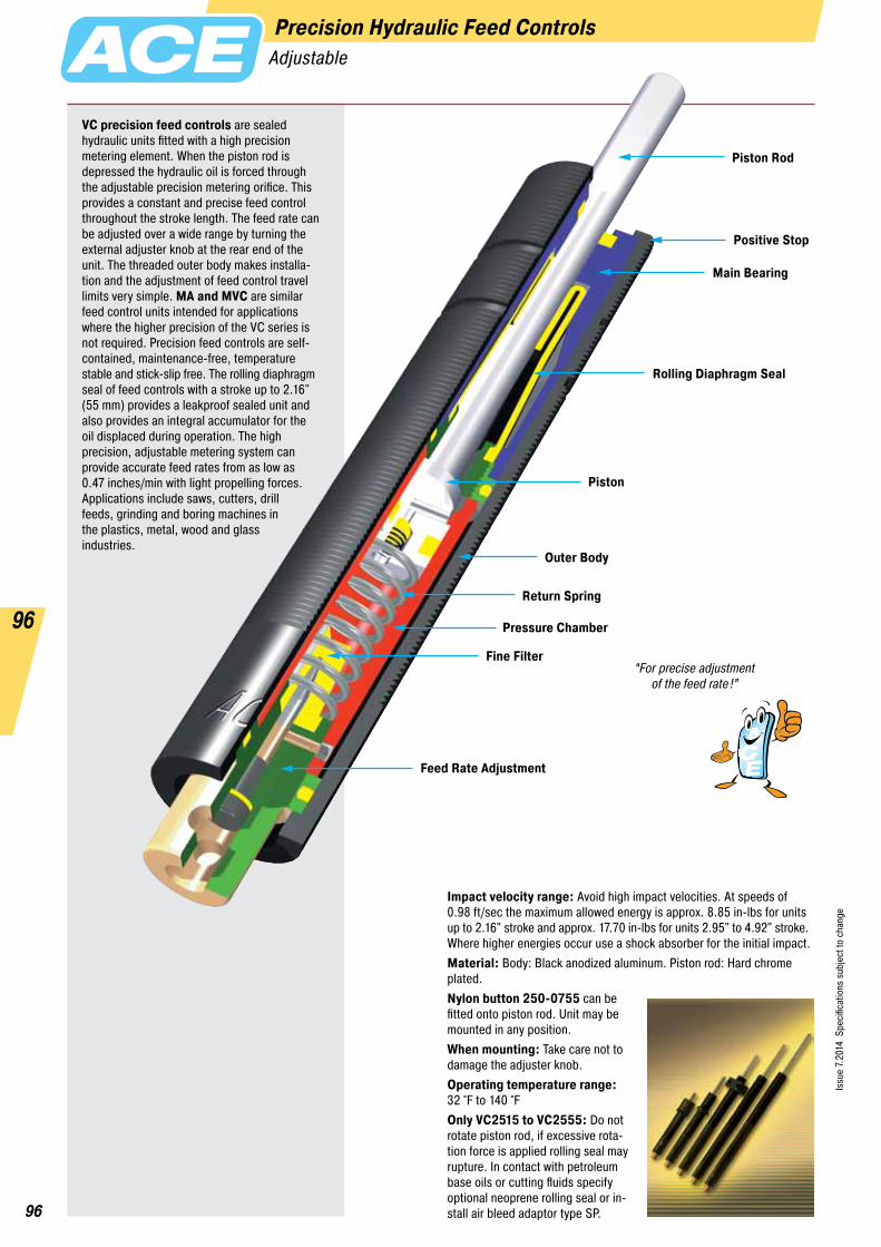
96
Issu
e 7.
2014
Spe
cific
atio
ns s
ubje
ct to
cha
nge
96
Precision Hydraulic Feed ControlsAdjustable
VC precision feed controls are sealed hydraulic units fitted with a high precision metering element. When the piston rod is depressed the hydraulic oil is forced through the adjustable precision metering orifice. This provides a constant and precise feed control throughout the stroke length. The feed rate can be adjusted over a wide range by turning the external adjuster knob at the rear end of the unit. The threaded outer body makes installa-tion and the adjustment of feed control travel limits very simple. MA and MVC are similar feed control units intended for applications where the higher precision of the VC series is not required. Precision feed controls are self- contained, maintenance-free, temperature stable and stick-slip free. The rolling diaphragm seal of feed controls with a stroke up to 2.16" (55 mm) provides a leakproof sealed unit and also provides an integral accumulator for the oil displaced during operation. The high precision, adjustable metering system can provide accurate feed rates from as low as 0.47 inches/min with light propelling forces. Applications include saws, cutters, drill feeds, grinding and boring machines in the plastics, metal, wood and glass industries.
Impact velocity range: Avoid high impact velocities. At speeds of 0.98 ft/sec the maximum allowed energy is approx. 8.85 in-lbs for units up to 2.16" stroke and approx. 17.70 in-lbs for units 2.95" to 4.92" stroke. Where higher energies occur use a shock absorber for the initial impact.Material: Body: Black anodized aluminum. Piston rod: Hard chrome plated.Nylon button 250-0755 can be fitted onto piston rod. Unit may be mounted in any position.When mounting: Take care not to damage the adjuster knob.Operating temperature range: 32 °F to 140 °FOnly VC2515 to VC2555: Do not rotate piston rod, if excessive rota- tion force is applied rolling seal may rupture. In contact with petroleum base oils or cutting fluids specify optional neoprene rolling seal or in- stall air bleed adaptor type SP.
Piston Rod
Piston
Main Bearing
Outer Body
Return Spring
Pressure Chamber
Fine Filter
Feed Rate Adjustment
Rolling Diaphragm Seal
Positive Stop
“For precise adjustment of the feed rate!”
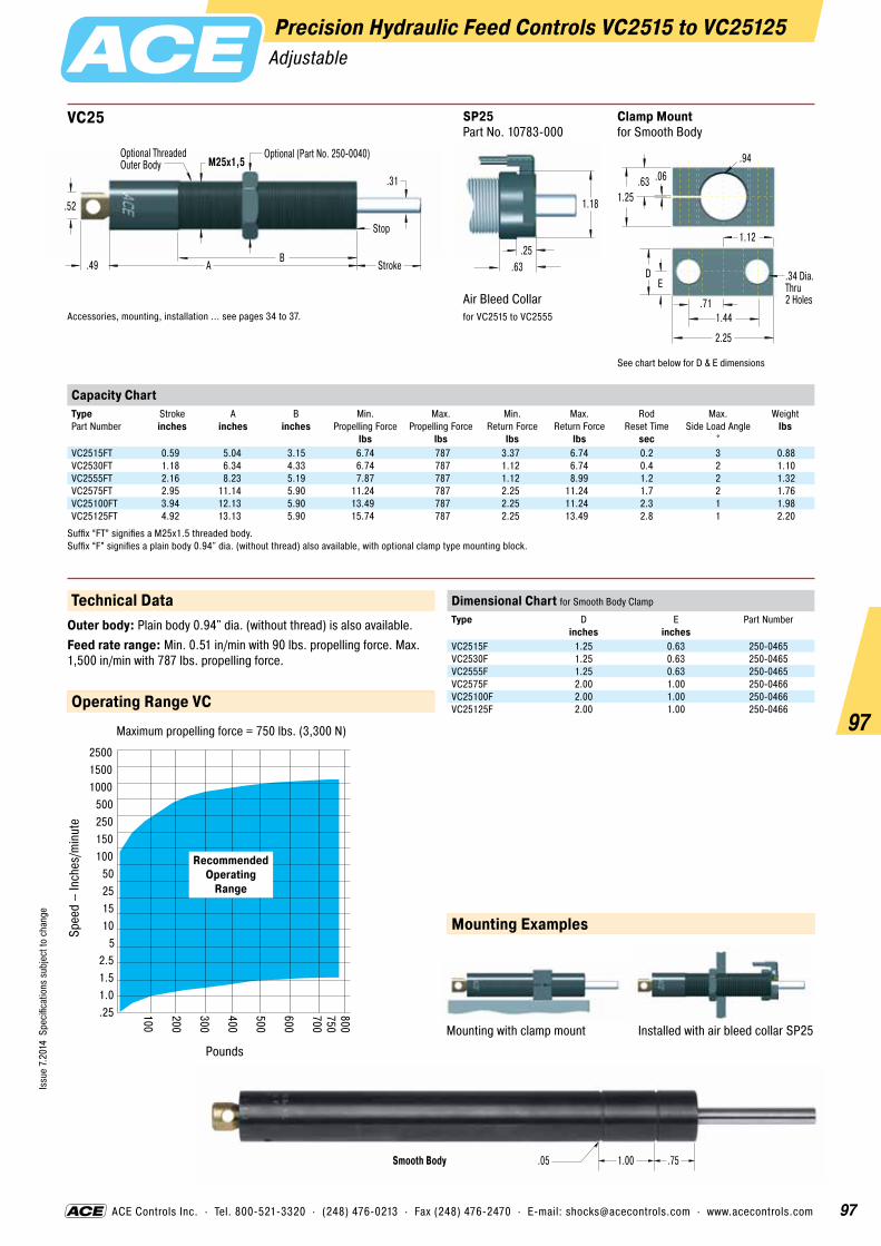
97
Issu
e 7.
2014
Spe
cific
atio
ns s
ubje
ct to
cha
nge
97
ACE Controls Inc. · Tel. 800-521-3320 · (248) 476-0213 · Fax (248) 476-2470 · E-mail: [email protected] · www.acecontrols.com
.05Smooth Body 1.00 .75
Precision Hydraulic Feed Controls VC2515 to VC25125Adjustable
.52
AB
Stroke
Stop
Optional (Part No. 250-0040)M25x1,5
.49
.31
Optional ThreadedOuter Body
VC25
Accessories, mounting, installation ... see pages 34 to 37.
Clamp Mountfor Smooth Body
See chart below for D & E dimensions
1.25
.94
.63 .06
1.44.71
2.25
1.12
ED .34 Dia.
Thru 2 Holes
SP25 Part No. 10783-000
Air Bleed Collarfor VC2515 to VC2555
.25.63
1.18
Capacity ChartType Part Number
Stroke inches
A inches
B inches
Min. Propelling Force
lbs
Max. Propelling Force
lbs
Min. Return Force
lbs
Max. Return Force
lbs
Rod Reset Time
sec
Max. Side Load Angle
°
Weight lbs
VC2515FT 0.59 5.04 3.15 6.74 787 3.37 6.74 0.2 3 0.88VC2530FT 1.18 6.34 4.33 6.74 787 1.12 6.74 0.4 2 1.10VC2555FT 2.16 8.23 5.19 7.87 787 1.12 8.99 1.2 2 1.32VC2575FT 2.95 11.14 5.90 11.24 787 2.25 11.24 1.7 2 1.76VC25100FT 3.94 12.13 5.90 13.49 787 2.25 11.24 2.3 1 1.98VC25125FT 4.92 13.13 5.90 15.74 787 2.25 13.49 2.8 1 2.20
Suffix “FT” signifies a M25x1.5 threaded body. Suffix “F” signifies a plain body 0.94" dia. (without thread) also available, with optional clamp type mounting block.
Operating Range VC
Pounds
Spee
d –
Inch
es/m
inut
e
Maximum propelling force = 750 lbs. (3,300 N)
250015001000
500250150100
50251510
52.51.51.0.25 800
750700
600
500
400
300
200
100
RecommendedOperating
Range
Technical DataOuter body: Plain body 0.94" dia. (without thread) is also available.Feed rate range: Min. 0.51 in/min with 90 lbs. propelling force. Max. 1,500 in/min with 787 lbs. propelling force.
Installed with air bleed collar SP25Mounting with clamp mount
Mounting Examples
Dimensional Chart for Smooth Body Clamp
Type
D inches
E inches
Part Number
VC2515F 1.25 0.63 250-0465VC2530F 1.25 0.63 250-0465VC2555F 1.25 0.63 250-0465VC2575F 2.00 1.00 250-0466VC25100F 2.00 1.00 250-0466VC25125F 2.00 1.00 250-0466

98
Issu
e 7.
2014
Spe
cific
atio
ns s
ubje
ct to
cha
nge
98
ACE Controls Inc. · Tel. 800-521-3320 · (248) 476-0213 · Fax (248) 476-2470 · E-mail: [email protected] · www.acecontrols.com
Feed Controls MA/MVCAdjustable
.12 StrokeAF .40.321.90 .52
.10.25M8x1.16
Adjustment Screw
.08
.10 ØØ
MA30M
Accessories, mounting, installation ... see pages 32 to 37.
.16 StrokeAF .47.281.86 .69
.12.30M10x1.20
Adjustment Screw
.12
.10 ØØ
MA50M
Accessories, mounting, installation ... see pages 32 to 37.
.13 StrokeAF .625.402.59 .72
.12.301/2-20 UNF.18
Adjustment Screw
.12
.10 ØØ
MA35
Accessories, mounting, installation ... see pages 33 to 37.
.19.25
.479/16-18 UNF.28 AF .49 .31
2.72
AF .87 .50.89
Stroke
Adjustment Screw
Ø
Ø
MA150
M14x1 also available to special order Accessories, mounting, installation ... see pages 33 to 37.
.19.18
.663/4-16 UNF.53 .31
3.46.75
1.18
StrokeAF .91
.19AF .71
Ø
Ø
Adjustment Knob
MVC225
Accessories, mounting, installation ... see pages 34 to 37.
.25.18
.901-12 UNF.65 .39
4.20 (5.43)1.00 (1.58)
1.43 (2.01)
StrokeAF 1.18
.20AF .91
Ø
Ø
Adjustment Knob
MVC600 and MVC900
Dimensions for MVC900 in ( )Accessories, mounting, installation ... see pages 34 to 37.
250-0307
Mounting Block
1.50
.98
.20
M10x1
.18.98
Ø
.24
250-0401
Mounting Block
2.00
1.50
3/4-16 UNF .22 Dia. Thru .33C’Bore x .45 Deep#10-32 Soc. Hd. Screw
1.50
.56
.31
.75
1.12
#10-32 Soc. Hd. ScrewThru 4 Holes
250-0402
Mounting Block
2.00
1.50
1-12 UNF .22 Dia. Thru .33C’Bore x .45 Deep#10-32 Soc. Hd. Screw
1.50
.56
.31
.75
1.12
#10-32 Soc. Hd. ScrewThru 4 Holes
250-0318
Mounting Block
1.81
1.37
9/16-18 UNF .21 Dia. Thru .32C’Bore x .32 Deep#10-32 Soc. Hd. Screw
1.38
.50
.31
.69
1.00
#10-32 Soc. Hd. ScrewThru 4 Holes
250-0308
Mounting Block
1.5
1.0
1/2-20 UNF .18 Dia. Thru .31C’Bore x .20 Deep#8-32 Soc. Hd. Screw
1.0
.28
#8-32 Soc. Hd. ScrewThru 2 Holes
.50

99
Issu
e 7.
2014
Spe
cific
atio
ns s
ubje
ct to
cha
nge
99
ACE Controls Inc. · Tel. 800-521-3320 · (248) 476-0213 · Fax (248) 476-2470 · E-mail: [email protected] · www.acecontrols.com
Precision Feed Control
Saw Blade
Profile
Striker
PrecisionFeed Control
PneumaticCylinder
Drill Spindle
Drill Bit
Drive
Operating Range MVC225 to 900 4000
3500
2500
2000
3000
1500
1000
500
12 24 36 6 12 24 36 6 12 24 36 6 12 24 36x 1 x 10 x 100 x 1000
MVC600MVC900
MVC225
Speed mm/min1 (mm/min) = 0.0394 in/min
Prop
ellin
g Fo
rce
N1
(N) =
0.2
25 lb
s
Technical DataImpact velocity range: Avoid high impact velocities. At speeds of 0.98 ft/sec the maximum allowed energy is approx. 17.70 in-lbs. Where higher energies occur use a shock absorber for the initial impact.Mounting: In any positionPositive stop: Integral mechanical stop built into the front of units.Material: Body: Steel with black oxide finish. Piston rod: Stainless steel.Operating temperature range: 32 °F to 150 °F
Feed Controls MA/MVCAdjustable
Drilling sheet metal
Sawing aluminium and plastic profiles
A high force is necessary at the start of drilling when the drill first contacts the sheet. After the initial cut this high force causes the drill to break through. This results in jagged edges rather than a smooth clean hole and also causes tool breakage. By installing an ACE VC feed control it is possible to precisely control the rate of drill advance. As a result the drilled holes are clean and consistent and drill breakage is considerably reduced.
Application Examples
Varying material types, hardness and wear on the saw blade causes the cutting pressure to vary greatly. However the saw advance speed should remain constant as changes cause breakage of the material being cut or of the saw blade. An ACE VC feed control fitted directly to the cutting head provides a simple and low cost solution. The cutting speed remains constant and can be easily preset.
Capacity ChartPropelling Force (lbs)
Type Part Number
Stroke inches
min. lbs
max. lbs
Min. Return Force
lbs
Max. Return Force
lbs
Rod Reset Time
sec
1 Max. Side Load Angle
°
Weight lbs
MA30M 0.32 2 18 1.16 1.57 0.30 2 0.02MA50M 0.28 9 36 0.47 1.8 0.30 2 0.05MA35 0.40 3.3 45 1.20 2.60 0.20 2 0.10MA150 0.50 4.5 67.4 0.70 1.20 0.40 2 0.12MVC225 0.75 5 400 1.05 2.15 0.65 2 0.28MVC600 1.00 14 800 2.40 6.87 0.85 2 0.67MVC900 1.58 15 800 2.40 7.40 0.95 2 0.87
1 For applications with higher side load angles consider using the side load adaptor page 36.

100
Issu
e 7.
2014
Spe
cific
atio
ns s
ubje
ct to
cha
nge
100
Hydraulic Speed/Feed Controls DVCAdjustable
Hydraulic speed/feed controls from ACE are maintenance-free, self-contained sealed units for precise control of speed in both directions of travel. The travel speed can be adjusted independently in each direction of travel. Applications include pick and place, machine slides and guards, flaps and hoods etc. The wide variety of mounting accessories make the DVC easy to install on many differ- ent types of application.
Positive stop: Provide mechanical stops 0.04 to 0.06 inch before end of each stroke direction.Operating fluid: Automatic Transmission Fluid (ATF)Material: Body: Black anodised aluminium. Piston rod: Hard chrome plated steel. End fittings: Zinc plated steel.Note: If unit has not moved for some time the seals may dry causing an increased break-away force on the initial cycle.Mounting: In any position. End fittings must be positively secured to prevent unscrewing.Operating temperature range: 32 °F to 149 °FOn request: Special oils and external finishes. Uni-directional damping (free flow in either direction).
Piston Rod
Outer Body
Main Bearing
Piston
Pressure Chamber
Accumulator
Thread forMountingAccessories
Adjustment Knobfor Extension Speed
Adjustment Knobfor Compression Speed
Rod Seal
“Travel speed can be adjusted independently
in each direction of travel !”
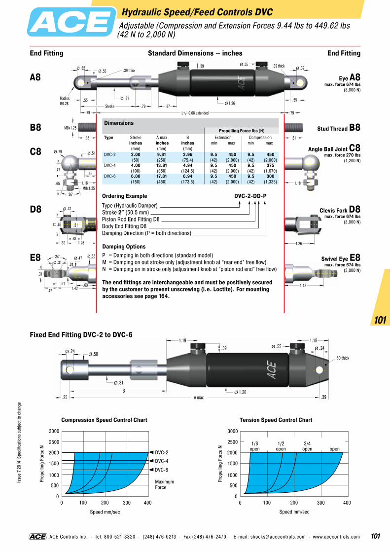
101
Issu
e 7.
2014
Spe
cific
atio
ns s
ubje
ct to
cha
nge
101
ACE Controls Inc. · Tel. 800-521-3320 · (248) 476-0213 · Fax (248) 476-2470 · E-mail: [email protected] · www.acecontrols.com
Hydraulic Speed/Feed Controls DVC Adjustable (Compression and Extension Forces 9.44 lbs to 449.62 lbs(42 N to 2,000 N)
.35
M8x1.25
1.18
.55
.55
.79 L+/- 0.08 extended
.31
.32
Stroke
RadiusR0.28
.39 thick
.79
.39 thick
1.26.55Ø
Ø
Ø
1.42
Ø
.31
.63
.31
.39 1.26
.63
Ø
Ø
1.18M8x1.25
.47
.79 .51
.59
.65
36°
Ø Ø
.31
.32
1.26
24° .47 .31
.31
.63
.63
.24
.47 1.42.51
ØØØ
.79 .87
.55Ø.39
End Fitting End FittingStandard Dimensions – inches
Ordering Example DVC-2-DD-PType (Hydraulic Damper)Stroke 2" (50.5 mm)Piston Rod End Fitting D8Body End Fitting D8Damping Direction (P = both directions)
Damping OptionsP = Damping in both directions (standard model)M = Damping on out stroke only (adjustment knob at “rear end” free flow)N = Damping on in stroke only (adjustment knob at “piston rod end” free flow)
The end fittings are interchangeable and must be positively secured by the customer to prevent unscrewing (i.e. Loctite). For mounting accessories see page 164.
.25 A max
.50
.31
.24
B 1.26
.55.391.19 1.18
.24
.50 thick
.39
ØØ
ØØ
Ø
Ø
3000
2500
2000
1500
1000
500
00 100 200 300 400
Speed mm/sec
Prop
ellin
g Fo
rce
N 1/8open
1/2open
3/4open open
Tension Speed Control Chart
3000
2500
2000
1500
1000
500
00 100 200 300
DVC-2
DVC-4
DVC-6
400
Maximum Force
Speed mm/sec
Prop
ellin
g Fo
rce
N
Compression Speed Control Chart
A8 Eye A8 max. force 674 lbs
(3,000 N)
B8 Stud Thread B8
C8 Angle Ball Joint C8 max. force 270 lbs
(1,200 N)
D8 Clevis Fork D8 max. force 674 lbs
(3,000 N)
E8 Swivel Eye E8 max. force 674 lbs
(3,000 N)
Fixed End Fitting DVC-2 to DVC-6
DimensionsPropelling Force lbs (N)
Type
Stroke inches (mm)
A max inches
(mm)
B inches (mm)
Extension min max
Compression min max
DVC-2 2.00 (50)
9.81 (250)
2.96(75.4)
9.5(42)
450(2,000)
9.5(42)
450(2,000)
DVC-4 4.00 (100)
13.81 (350)
4.94(124.5)
9.5(42)
450(2,000)
9.5(42)
375(1,670)
DVC-6 6.00 (150)
17.81 (450)
6.94(173.8)
9.5(42)
450(2,000)
9.5(42)
300(1,335)
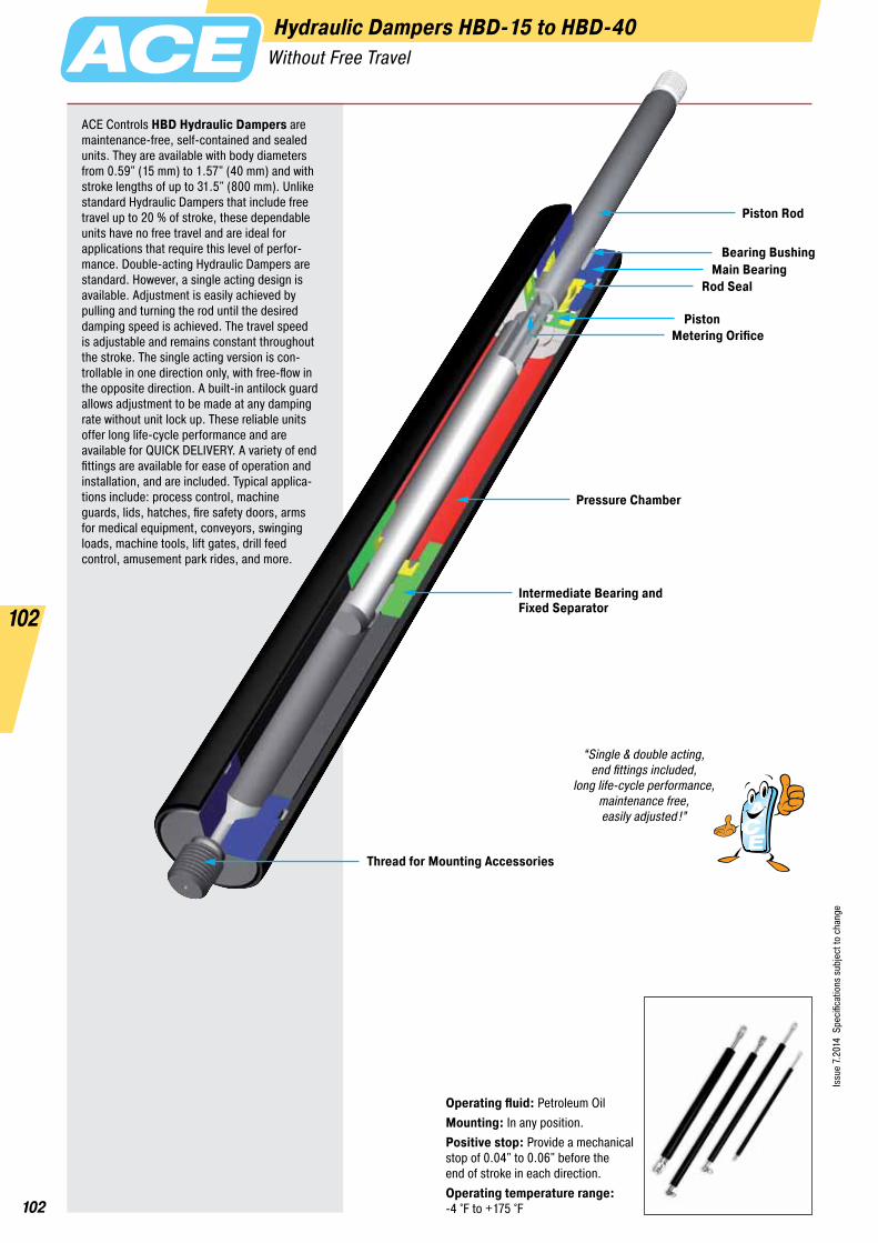
102
Issu
e 7.
2014
Spe
cific
atio
ns s
ubje
ct to
cha
nge
102
Hydraulic Dampers HBD-15 to HBD-40Without Free Travel
Operating fluid: Petroleum OilMounting: In any position.Positive stop: Provide a mechanical stop of 0.04" to 0.06" before the end of stroke in each direction.Operating temperature range: -4 °F to +175 °F
Piston Rod
Main Bearing
Pressure Chamber
Intermediate Bearing andFixed Separator
Thread for Mounting Accessories
Rod Seal
PistonMetering Orifice
Bearing Bushing
ACE Controls HBD Hydraulic Dampers are maintenance-free, self-contained and sealed units. They are available with body diameters from 0.59" (15 mm) to 1.57" (40 mm) and with stroke lengths of up to 31.5" (800 mm). Unlike standard Hydraulic Dampers that include free travel up to 20 % of stroke, these dependable units have no free travel and are ideal for applications that require this level of perfor-mance. Double-acting Hydraulic Dampers are standard. However, a single acting design is available. Adjustment is easily achieved by pulling and turning the rod until the desired damping speed is achieved. The travel speed is adjustable and remains constant throughout the stroke. The single acting version is con- trollable in one direction only, with free-flow in the opposite direction. A built-in antilock guard allows adjustment to be made at any damping rate without unit lock up. These reliable units offer long life-cycle performance and are available for QUICK DELIVERY. A variety of end fittings are available for ease of operation and installation, and are included. Typical applica- tions include: process control, machine guards, lids, hatches, fire safety doors, arms for medical equipment, conveyors, swinging loads, machine tools, lift gates, drill feed control, amusement park rides, and more.
“Single & double acting,end fittings included,
long life-cycle performance,maintenance free,easily adjusted!”

103
Issu
e 7.
2014
Spe
cific
atio
ns s
ubje
ct to
cha
nge
103
ACE Controls Inc. · Tel. 800-521-3320 · (248) 476-0213 · Fax (248) 476-2470 · E-mail: [email protected] · www.acecontrols.com
Hydraulic Dampers HBD-15 Adjustable [Compression and Extension Forces 8 lbs to 180 lbs (35 N to 800 N)] – Without Free Travel
.59
.63
.85
.12 thickR0.20.33
.43
End Fitting End FittingStandard Dimensions – inches
24° .39 .24
.24
.20
.39
.20
.24 .79
.39
.20
M5x0.8
.87M5x0.8
.31
.51 .31
.47
.39
36°
.47
.51
.18
.39 1.18.47
Ø
Ø Ø
ØØ
Ø
1.18
.79
.87
.20
.24
Stroke.27
.24
L+/- 0.08 extended+ max 0.24 at maximum adjustment
DimensionsType
Stroke inches (mm)
L extended inches (mm)
1 Max. Compression Force
lbs (N)HBD-15-25 0.98 (25) 5.71 (145) 179.85 (800)HBD-15-50 1.97 (50) 8.66 (220) 179.85 (800)HBD-15-75 2.95 (75) 11.61 (295) 179.85 (800)HBD-15-100 3.94 (100) 14.57 (370) 78.68 (350)HBD-15-150 5.91 (150) 20.47 (520) 67.44 (300)
1 Max. extension force for all stroke lengths 179.85 lbs (800 N).
Ordering Example HBD-15-150-AA-PType (Hydraulic Damper)Body Ø 0.59" (15 mm)Stroke 5.91" (150 mm)Piston Rod End Fitting A5Body End Fitting A5Damping Direction (P = in both directions)
Damping OptionsP = Damping in both directionsN = Damping on in stroke onlyM = Damping on out stroke onlyX = Special model suffix
If considering utilization of hydraulic dampers in parallel, please contact ACE. For mounting accessories see page 163.
Technical DataOn request: Stainless steel, units with other damping characteristics, other stroke lengths and alternative end fittings.Mounting: In any position. Adjustment: Pull the piston rod out to its fully extended position. While pulling on the rod, turn it clockwise or counter-clockwise until the desired damping is achieved. The adjustment is multi-turn and correct damping may require several trial and error adjustments. A built-in antilock guard allows adjustments to be made at any damping rate without unit lock up.Positive stop: Provide mechanical stops 0.04" to 0.06" (1 to 1.5 mm) before end of each stroke direction.Material: Body: Black anodized aluminum. Piston rod: Chrome steel. End fittings: Zinc plated steel.Mounting brackets: A & E end fittings adapt to mounting bracket GSB-01. C end fitting, minus threaded stud adapts to GSB-02.
A5 Eye A5 max. force 180 lbs
(800 N)
B5 Stud Thread B5
C5 Angle Ball Joint C5
max. force 112 lbs(500 N)
D5 Clevis Fork D5 max. force 180 lbs
(800 N)
E5 Swivel Eye E5 max. force 180 lbs
(800 N)
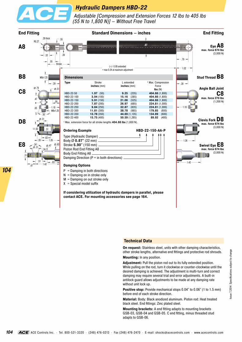
104
Issu
e 7.
2014
Spe
cific
atio
ns s
ubje
ct to
cha
nge
104
ACE Controls Inc. · Tel. 800-521-3320 · (248) 476-0213 · Fax (248) 476-2470 · E-mail: [email protected] · www.acecontrols.com
Hydraulic Dampers HBD-22 Adjustable [Compression and Extension Forces 12 lbs to 405 lbs (55 N to 1,800 N)] – Without Free Travel
.39
.87
.79
Stroke
1.02
.55
.39 thick
.32
.55
End Fitting End FittingStandard Dimensions – inches
R0.27
1.42
1.2624° .47
.31
.31
.31
.63
.31
.39 1.26
.63
.39
M8x1.25
1.181.18M8x1.25
.47
.79 .51
.59
.65
36°
.63
.63
.24
.47 1.42.51
Ø
Ø Ø
ØØ
.39
Ø
L+/- 0.08 extended+ max 0.24 at maximum adjustment
DimensionsType
Stroke inches (mm)
L extended inches (mm)
1 Max. Compression Force
lbs (N)HBD-22-50 1.97 (50) 9.25 (235) 404.66 (1,800)HBD-22-100 3.94 (100) 15.16 (385) 404.66 (1,800)HBD-22-150 5.91 (150) 21.06 (525) 404.66 (1,800)HBD-22-200 7.87 (200) 26.97 (685) 224.81 (1,000)HBD-22-250 9.84 (250) 32.87 (835) 224.81 (1,000)HBD-22-300 11.81 (300) 38.78 (985) 179.85 (800)HBD-22-350 13.78 (350) 44.69 (1,135) 134.89 (600)HBD-22-400 15.75 (400) 50.59 (1,285) 89.92 (400)
1 Max. extension force for all stroke lengths 404.66 lbs (1,800 N).
Ordering Example HBD-22-150-AA-PType (Hydraulic Damper)Body Ø 0.87" (22 mm)Stroke 5.90" (150 mm)Piston Rod End Fitting A8Body End Fitting A8Damping Direction (P = in both directions)
Damping OptionsP = Damping in both directionsN = Damping on in stroke onlyM = Damping on out stroke onlyX = Special model suffix
If considering utilization of hydraulic dampers in parallel, please contact ACE. For mounting accessories see page 164.
Technical DataOn request: Stainless steel, units with other damping characteristics, other stroke lengths, alternative end fittings and protective rod shrouds.Mounting: In any position.Adjustment: Pull the piston rod out to its fully extended position. While pulling on the rod, turn it clockwise or counter-clockwise until the desired damping is achieved. The adjustment is multi-turn and correct damping may require several trial and error adjustments. A built-in antilock guard allows adjustments to be made at any damping rate without unit lock up.Positive stop: Provide mechanical stops 0.04" to 0.06" (1 to 1.5 mm) before end of each stroke direction.Material: Body: Black anodized aluminum. Piston rod: Heat treated black steel. End fittings: Zinc plated steel.Mounting brackets: A end fitting adapts to mounting brackets GSB-03, GSB-04 and GSB-05. C end fitting, minus threaded stud adapts to GSB-06.
B8 Stud Thread B8
C8 Angle Ball Joint C8
max. force 270 lbs(1,200 N)
D8 Clevis Fork D8 max. force 674 lbs
(3,000 N)
E8 Swivel Eye E8 max. force 674 lbs
(3,000 N)
A8 Eye A8 max. force 674 lbs
(3,000 N)

105
Issu
e 7.
2014
Spe
cific
atio
ns s
ubje
ct to
cha
nge
105
ACE Controls Inc. · Tel. 800-521-3320 · (248) 476-0213 · Fax (248) 476-2470 · E-mail: [email protected] · www.acecontrols.com
Hydraulic Dampers HBD-28 Adjustable [Compression and Extension Forces 16 lbs to 674 lbs (70 N to 3,000 N)] – Without Free Travel
.39
1.10
.79
Stroke1.02
.55
.39 thick
.32
.55
End Fitting End FittingStandard Dimensions – inches
R0.27
1.42
1.2624° .47
.31
.31
.31
.63
.31
.39 1.26
.63
.39
M8x1.25
1.181.18M8x1.25
.47
.79 .51
.59
.65
36°
.63
.63
.24
.47 1.42.51
Ø
Ø Ø
ØØ
.39
Ø
L+/- 0.08 extended+ max 0.24 at maximum adjustment
DimensionsType
Stroke inches (mm)
L extended inches (mm)
1 Max. Compression Force
lbs (N)HBD-28-50 1.97 (50) 9.85 (250) 674.43 (3,000)HBD-28-100 3.94 (100) 15.75 (400) 674.43 (3,000)HBD-28-150 5.91 (150) 21.66 (550) 674.43 (3,000)HBD-28-200 7.87 (200) 27.56 (700) 674.43 (3,000)HBD-28-250 9.84 (250) 33.47 (850) 674.43 (3,000)HBD-28-300 11.81 (300) 39.37 (1,000) 562.03 (2,500)HBD-28-350 13.78 (350) 45.28 (1,150) 449.62 (2,000)HBD-28-400 15.75 (400) 51.19 (1,300) 337.22 (1,500)HBD-28-500 19.69 (500) 63.00 (1,600) 224.81 (1,000)
1 Max. extension force for all stroke lengths 674.43 lbs (3,000 N).
Ordering Example HBD-28-150-AA-PType (Hydraulic Damper)Body Ø 1.10" (28 mm)Stroke 5.91" (150 mm)Piston Rod End Fitting A8Body End Fitting A8Damping Direction (P = in both directions)
Damping OptionsP = Damping in both directionsN = Damping on in stroke onlyM = Damping on out stroke onlyX = Special model suffix
If considering utilization of hydraulic dampers in parallel, please contact ACE. For mounting accessories see page 164.
Technical DataOn request: Stainless steel, units with other damping characteristics, other stroke lengths, alternative end fittings and protective rod shrouds.Mounting: In any position. Adjustment: Pull the piston rod out to its fully extended position. While pulling on the rod, turn it clockwise or counter-clockwise until the desired damping is achieved. The adjustment is multi-turn and correct damping may require several trial and error adjustments. A built-in antilock guard allows adjustments to be made at any damping rate without unit lock up.Positive stop: Provide mechanical stops 0.04" to 0.06" (1 to 1.5 mm) before end of each stroke direction.Material: Body: Black anodized aluminum. Piston rod: Chrome steel. End fittings: Zinc plated steel.Mounting brackets: A end fitting adapts to mounting brackets GSB-03, GSB-04 and GSB-05. C end fitting, minus threaded stud adapts to GSB-06.
A8 Eye A8 max. force 674 lbs
(3,000 N)
B8 Stud Thread B8
C8 Angle Ball Joint C8
max. force 270 lbs(1,200 N)
D8 Clevis Fork D8 max. force 674 lbs
(3,000 N)
E8 Swivel Eye E8 max. force 674 lbs
(3,000 N)

106
Issu
e 7.
2014
Spe
cific
atio
ns s
ubje
ct to
cha
nge
106
ACE Controls Inc. · Tel. 800-521-3320 · (248) 476-0213 · Fax (248) 476-2470 · E-mail: [email protected] · www.acecontrols.com
Hydraulic Dampers HBD-40 Adjustable [Compression and Extension Forces 18 lbs to 2,248 lbs (80 N to 10,000 N)] – Without Free Travel
.55
1.57
1.57
Stroke2.05
.82
.55 thick
.55
.98
End Fitting End FittingStandard Dimensions – inches
R0.49
2.2
.55
1.06
.55
.63 2.2
1.06
.59
M14x1.5
1.771.77M14x1.5
.79
1.18 .87
.98
1.1
36°
Ø
Ø Ø
2.24
.59
30° .79 .55
.75
1.18
1.02
.51
.71 2.24.71
ØØØ
L+/- 0.08 extended+ max 0.24 at maximum adjustment
DimensionsType
Stroke inches (mm)
L extended inches (mm)
1 Max. Compression Force
lbs (N)HBD-40-100 3.94 (100) 16.93 (430) 2,248.10 (10,000)HBD-40-150 5.91 (150) 22.83 (580) 2,248.10 (10,000)HBD-40-200 7.87 (200) 28.74 (730) 2,248.10 (10,000)HBD-40-300 11.81 (300) 40.55 (1,030) 2,248.10 (10,000)HBD-40-400 15.75 (400) 52.36 (1,330) 1,798.48 (8,000)HBD-40-500 19.69 (500) 64.17 (1,630) 1,348.86 (6,000)HBD-40-600 23.62 (600) 75.98 (1,930) 899.24 (4,000)HBD-40-700 27.56 (700) 87.80 (2,230) 674.43 (3,000)HBD-40-800 31.50 (800) 99.61 (2,530) 449.62 (2,000)
1 Max. extension force for all stroke lengths 2,248.10 lbs (10,000 N).
Ordering Example HBD-40-300-AA-PType (Hydraulic Damper)Body Ø 1.57" (40 mm)Stroke 11.81" (300 mm)Piston Rod End Fitting A14Body End Fitting A14Damping Direction (P = in both directions)
Damping OptionsP = Damping in both directionsN = Damping on in stroke onlyM = Damping on out stroke onlyX = Special model suffix
If considering utilization of hydraulic dampers in parallel, please contact ACE. For mounting accessories see page 165.
Technical DataOn request: Stainless steel, units with other damping characteristics, other stroke lengths, alternative end fittings and protective rod shrouds.Mounting: In any position.Adjustment: Pull the piston rod out to its fully extended position. While pulling on the rod, turn it clockwise or counter-clockwise until the desired damping is achieved. The adjustment is multi-turn and correct damping may require several trial and error adjustments. A built-in antilock guard allows adjustments to be made at any damping rate without unit lock up.Positive stop: Provide mechanical stops 0.04" to 0.06" (1 to 1.5 mm) before end of each stroke direction.Material: Body: Black anodized aluminum. Piston rod: Chrome steel. End fittings: Zinc plated steel.Mounting brackets: A and E end fittings adapt to mounting bracket ME14.
A14 Eye A14 max. force 2,248 lbs
(10,000 N)
B14 Stud Thread B14
C14 Angle Ball Joint C14
max. force 719 lbs (3,200 N)
D14 Clevis Fork D14 max. force 2,248 lbs
(10,000 N)
E14 Swivel Eye E14 max. force 2,248 lbs
(10,000 N)

107
Issu
e 7.
2014
Spe
cific
atio
ns s
ubje
ct to
cha
nge
107
Hydraulic Dampers HB-12 to HB-70Adjustable
Hydraulic dampers from ACE are mainte-nance-free, self-contained and sealed units. They are available with body diameters from 0.47" (12 mm) to 2.76" (70 mm) and with stroke lengths of up to 31.50" (800 mm). As standard they are supplied as double acting dampers but a single acting version is also available. The single acting version is con- trollable in one direction only, with free flow in the opposite direction. The travel speed is adjustable and remains constant throughout the stroke. The new adjustment segment on the piston makes sensitive speed adjustment easy. ACE’s hydraulic dampers sport the sleek design of our gas springs. The anodized aluminum body and the piston rod with a special wear-resistant coating provide an exceptionally long lifetime and excellent corrosion protec-tion. A wide range of screw on mounting accessories make them very versatile and easy to install. Typical applications include machine guards and lids, fire safety flaps and doors, damping oscillations of suspended loads (Power and Free Systems) etc.
Function: The stepless adjustment of the damping rate is achieved by pulling (or pushing) the piston rod to its fully extended (or compressed) position and then turning the piston rod.Operating fluid: HB-12 and HB-70: Hydraulic oil. HB-15 to HB-40: Petroleum oil.Mounting: In any position. End fittings must be positively secured to prevent unscrewing.Operating temperature range: -4 °F to 175 °FOn request: Special lengths, alternative seals and end fittings.
Piston Rod
Piston
Main Bearing
Pressure Chamber
Outer Body
Thread forMountingAccessories
Rod Seal
Metering Orifice

108
Issu
e 7.
2014
Spe
cific
atio
ns s
ubje
ct to
cha
nge
108
ACE Controls Inc. · Tel. 800-521-3320 · (248) 476-0213 · Fax (248) 476-2470 · E-mail: [email protected] · www.acecontrols.com
Hydraulic Dampers HB-12 Adjustable [Compression and Extension Forces 4 lbs to 40 lbs (20 N to 180 N)]
.47
End Fitting End FittingStandard Dimensions – inches
24° .31
.16
.20
.21
.28 .47.29
ØØ
.28
.71.71
.16
.51 .31
.24.31
.20
M3.5x0.6
.71
.31
.31
.47 L+/- 0.08 extended
.16
.16
StrokeRadiusR0.16
.16 thick
.47
.16 thick
.47 .31
L = Stroke + 0.39
.61
ØØ
Ø
Ø Ø
ØØ
.16
.31
.16
.20 .63
.31
Ø
Ø
Ø
.71M4x0.7
.33
.51 .31
.24
.39
36°
Ø Ø
.20
.16
.63
M3.5x0.6DimensionsType
Stroke inches (mm)
L extendedinches (mm)
1 Max. Compression Force
lbs (N)HB-12-10 0.39 (10) 2.17 (55) 40.47 (180)HB-12-20 0.79 (20) 2.95 (75) 40.47 (180)HB-12-30 1.18 (30) 3.74 (95) 40.47 (180)HB-12-40 1.57 (40) 4.53 (115) 40.47 (180)HB-12-50 1.97 (50) 5.31 (135) 40.47 (180)HB-12-60 2.36 (60) 6.10 (155) 40.47 (180)HB-12-70 2.76 (70) 6.89 (175) 40.47 (180)HB-12-80 3.15 (80) 7.68 (195) 33.72 (150)
1 Max. extension force for all stroke lengths 40.47 lbs (180 N).
Ordering Example HB-12-30-AC-MType (Hydraulic Damper)Body Ø 0.47" (12 mm)Stroke 1.18" (30 mm)Piston Rod End Fitting A3.5Body End Fitting C3.5Damping Direction (M = out stroke only)
Damping OptionsP = Damping in both directionsN = Damping on in stroke onlyM = Damping on out stroke onlyX = Special model suffix
The end fittings are interchangeable and must be positively secured by the customer to prevent unscrewing (i.e. Loctite). For mounting acces-sories see page 163.
A3.5C3.5
D3.5E3.5
G3.5NA3.5
OA3.5A3.5
OG3.5
NG3.5
Technical DataAdjustment: Adjustment of the damping rate is achieved by pulling (or pushing) the piston rod to its fully extended (or compressed) position. Whilst still pulling the piston rod turn it clockwise to increase damping and anti-clockwise to decrease damping. If the resistance increases noticeably, stop adjusting to avoid damage. The adjustment can add a max. of 0.24" (6 mm) to the L dim. shown (adjustment instruction see page 116).Positive stop: Provide mechanical stops 0.04" to 0.06" (1 to 1.5 mm) before end of each stroke direction.Free travel: Construction of standard damper results in a free travel of approx. 21 % of stroke.Material: Body: Black coated steel. Piston rod: Stainless steel AISI 303. End fittings: Zinc plated steel.Separator piston: Available as a special option to remove free travel. Also provides extension force of min. 4.50 lbs. (20 N). Dimension: L = 2.6 x stroke + 1.61" (41 mm). Part number: Add suffix -T.
A3.5 Eye A3.5 max. force 83 lbs
(370 N)
B3.5Stud Thread
B3.5
C3.5Angle Ball Joint
C3.5 max. force 83 lbs
(370 N)
D3.5Clevis Fork
D3.5 max. force 83 lbs
(370 N)
E3.5Swivel Eye
E3.5 max. force 83 lbs
(370 N)
G3.5Ball Socket
G3.5 max. force 83 lbs
(370 N)
Rod ShroudW3.5-12
HB-12
For mounting accessories see page 163.

109
Issu
e 7.
2014
Spe
cific
atio
ns s
ubje
ct to
cha
nge
109
ACE Controls Inc. · Tel. 800-521-3320 · (248) 476-0213 · Fax (248) 476-2470 · E-mail: [email protected] · www.acecontrols.com
Hydraulic Dampers HB-15 Adjustable [Compression and Extension Forces 4 lbs to 180 lbs (20 N to 800 N)]
.24
.59
.63
Stroke.85
.27
.12 thickR0.20
.24
.33
.43
End Fitting End FittingStandard Dimensions – inches
1.18
.7924° .39
.24
.24
.20
.39
.20
.24 .79
.39
.20
M5x0.8
.87.87M5x0.8
.31
.51 .31
.47
.39
36°
.47
.51
.18
.39 1.18.47
Ø
Ø Ø
ØØ
.20
Ø
L+/- 0.08 extended+ max 0.24 at maximum adjustment
DimensionsType
Stroke inches (mm)
L extended inches (mm)
1 Max. Compression Force
lbs (N)HB-15-25 0.98 (25) 3.54 (90) 179.85 (800)HB-15-50 1.97 (50) 5.51 (140) 179.85 (800)HB-15-75 2.95 (75) 7.48 (190) 179.85 (800)HB-15-100 3.94 (100) 9.45 (240) 78.68 (350)HB-15-150 5.91 (150) 13.39 (340) 67.44 (300)
1 Max. extension force for all stroke lengths 179.85 lbs (800 N).
Ordering Example HB-15-150-AA-PType (Hydraulic Damper)Body Ø 0.59" (15 mm)Stroke 5.91" (150 mm)Piston Rod End Fitting A5Body End Fitting A5Damping Direction (P = in both directions)
Damping OptionsP = Damping in both directionsN = Damping on in stroke onlyM = Damping on out stroke onlyX = Special model suffix
If considering utilization of hydraulic dampers in parallel, please contact ACE. For mounting accessories see page 163.
Technical DataOn request: Stainless steel, units with other damping characteristics, other stroke lengths and alternative end fittings.Mounting: In any position. Adjustment: Adjustment of the damping rate is achieved by pulling (or pushing) the piston rod to its fully extended (or compressed) position. While pulling on the rod, turn it clockwise or counter-clockwise until the desired damping is achieved. The adjustment is multi-turn and correct damping may require several trial and error adjustments. A built-in antilock guard allows adjustments to be made at any damping rate without unit lock up.Positive stop: Provide mechanical stops 0.04" to 0.06" (1 to 1.5 mm) before end of each stroke direction.Free travel: Dampers have free travel accounting for up to 20 % of stroke.Material: Body: Black anodized aluminum. Piston rod: Steel, wear-resistant. End fittings: Zinc plated steel.Mounting brackets: A & E end fittings adapt to mounting bracket GSB-01. C end fitting, minus threaded stud adapts to GSB-02.
A5 Eye A5 max. force 180 lbs
(800 N)
B5 Stud Thread B5
C5 Angle Ball Joint C5
max. force 112 lbs(500 N)
D5 Clevis Fork D5 max. force 180 lbs
(800 N)
E5 Swivel Eye E5 max. force 180 lbs
(800 N)

110
Issu
e 7.
2014
Spe
cific
atio
ns s
ubje
ct to
cha
nge
110
ACE Controls Inc. · Tel. 800-521-3320 · (248) 476-0213 · Fax (248) 476-2470 · E-mail: [email protected] · www.acecontrols.com
Hydraulic Dampers HB-22 Adjustable [Compression and Extension Forces 7 lbs to 405 lbs(30 N to 1,800 N)]
.31
.87
.79
Stroke
1.02
.55
.39 thick
.32
.55
End Fitting End FittingStandard Dimensions – inches
R0.27
1.42
1.2624° .47
.31
.31
.31
.63
.31
.39 1.26
.63
.39
M8x1.25
1.181.18M8x1.25
.47
.79 .51
.59
.65
36°
.63
.63
.24
.47 1.42.51
Ø
Ø Ø
ØØ
.39
Ø
L+/- 0.08 extended+ max 0.24 at maximum adjustment
DimensionsType
Stroke inches (mm)
L extended inches (mm)
1 Max. Compression Force
lbs (N)HB-22-50 1.97 (50) 5.90 (150) 404.66 (1,800)HB-22-100 3.94 (100) 9.84 (250) 404.66 (1,800)HB-22-150 5.91 (150) 13.78 (350) 404.66 (1,800)HB-22-200 7.87 (200) 17.72 (450) 224.81 (1,000)HB-22-250 9.84 (250) 21.65 (550) 224.81 (1,000)HB-22-300 11.81 (300) 25.58 (650) 179.85 (800)HB-22-350 13.78 (350) 29.52 (750) 134.89 (600)HB-22-400 15.75 (400) 33.46 (850) 89.92 (400)
1 Max. extension force for all stroke lengths 404.66 lbs (1,800 N).
Ordering Example HB-22-150-AA-PType (Hydraulic Damper)Body Ø 0.87" (22 mm)Stroke 5.90" (150 mm)Piston Rod End Fitting A8Body End Fitting A8Damping Direction (P = in both directions)
Damping OptionsP = Damping in both directionsN = Damping on in stroke onlyM = Damping on out stroke onlyX = Special model suffix
If considering utilization of hydraulic dampers in parallel, please contact ACE. For mounting accessories see page 164.
Technical DataOn request: Stainless steel, units with other damping characteristics, other stroke lengths, alternative end fittings and protective rod shrouds.Mounting: In any position.Adjustment: Adjustment of the damping rate is achieved by pulling (or pushing) the piston rod to its fully extended (or compressed) position. While pulling on the rod, turn it clockwise or counter-clockwise until the desired damping is achieved. The adjustment is multi-turn and correct damping may require several trial and error adjustments. A built-in antilock guard allows adjustments to be made at any damping rate without unit lock up.Positive stop: Provide mechanical stops 0.04" to 0.06" (1 to 1.5 mm) before end of each stroke direction.Free travel: Dampers have free travel accounting for up to 15 % of stroke.Material: Body: Black anodized aluminum. Piston rod: Steel, wear-resistant. End fittings: Zinc plated steel.Mounting brackets: A end fitting adapts to mounting brackets GSB-03, GSB-04 and GSB-05. C end fitting, minus threaded stud adapts to GSB-06.
A8 Eye A8 max. force 674 lbs
(3,000 N)
B8 Stud Thread B8
C8 Angle Ball Joint C8
max. force 270 lbs(1,200 N)
D8 Clevis Fork D8 max. force 674 lbs
(3,000 N)
E8 Swivel Eye E8 max. force 674 lbs
(3,000 N)

111
Issu
e 7.
2014
Spe
cific
atio
ns s
ubje
ct to
cha
nge
111
ACE Controls Inc. · Tel. 800-521-3320 · (248) 476-0213 · Fax (248) 476-2470 · E-mail: [email protected] · www.acecontrols.com
Hydraulic Dampers HB-28
.39
1.10
.79
Stroke1.02
.55
.39 thick
.32
.55
End Fitting End FittingStandard Dimensions – inches
R0.27
1.42
1.2624° .47
.31
.31
.31
.63
.31
.39 1.26
.63
.39
M8x1.25
1.181.18M8x1.25
.47
.79 .51
.59
.65
36°
.63
.63
.24
.47 1.42.51
Ø
Ø Ø
ØØ
.39
Ø
L+/- 0.08 extended+ max 0.24 at maximum adjustment
DimensionsType
Stroke inches (mm)
L extended inches (mm)
1 Max. Compression Force
lbs (N)HB-28-50 1.97 (50) 6.30 (160) 674.43 (3,000)HB-28-100 3.94 (100) 10.24 (260) 674.43 (3,000)HB-28-150 5.91 (150) 14.17 (360) 674.43 (3,000)HB-28-200 7.87 (200) 18.11 (460) 674.43 (3,000)HB-28-250 9.84 (250) 22.05 (560) 674.43 (3,000)HB-28-300 11.81 (300) 25.98 (660) 562.03 (2,500)HB-28-350 13.78 (350) 29.92 (760) 449.62 (2,000)HB-28-400 15.75 (400) 33.86 (860) 337.22 (1,500)HB-28-500 19.69 (500) 41.73 (1,060) 224.81 (1,000)
1 Max. extension force for all stroke lengths 674.43 lbs (3,000 N).
Ordering Example HB-28-150-AA-PType (Hydraulic Damper)Body Ø 1.10" (28 mm)Stroke 5.91" (150 mm)Piston Rod End Fitting A8Body End Fitting A8Damping Direction (P = in both directions)
Damping OptionsP = Damping in both directionsN = Damping on in stroke onlyM = Damping on out stroke onlyX = Special model suffix
If considering utilization of hydraulic dampers in parallel, please contact ACE. For mounting accessories see page 164.
Technical DataOn request: Stainless steel, units with other damping characteristics, other stroke lengths, alternative end fittings and protective rod shrouds.Mounting: In any position. Adjustment: Adjustment of the damping rate is achieved by pulling (or pushing) the piston rod to its fully extended (or compressed) position. While pulling on the rod, turn it clockwise or counter-clockwise until the desired damping is achieved. The adjustment is multi-turn and correct damping may require several trial and error adjustments. A built-in antilock guard allows adjustments to be made at any damping rate without unit lock up.Positive stop: Provide mechanical stops 0.04" to 0.06" (1 to 1.5 mm) before end of each stroke direction.Free travel: Dampers have free travel accounting for up to 15 % of stroke.Material: Body: Black anodized aluminum. Piston rod: Steel, wear-resistant. End fittings: Zinc plated steel.Mounting brackets: A end fitting adapts to mounting brackets GSB-03, GSB-04 and GSB-05. C end fitting, minus threaded stud adapts to GSB-06.
Adjustable [Compression and Extension Forces 7 lbs to 674 lbs (30 N to 3,000 N)]
A8 Eye A8 max. force 674 lbs
(3,000 N)
B8 Stud Thread B8
C8 Angle Ball Joint C8
max. force 270 lbs(1,200 N)
D8 Clevis Fork D8 max. force 674 lbs
(3,000 N)
E8 Swivel Eye E8 max. force 674 lbs
(3,000 N)
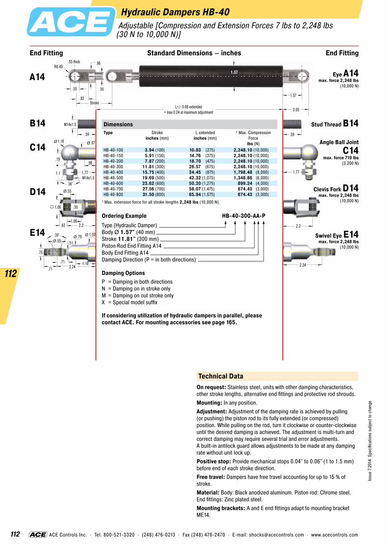
112
Issu
e 7.
2014
Spe
cific
atio
ns s
ubje
ct to
cha
nge
112
ACE Controls Inc. · Tel. 800-521-3320 · (248) 476-0213 · Fax (248) 476-2470 · E-mail: [email protected] · www.acecontrols.com
Hydraulic Dampers HB-40
.55
1.57
1.57
Stroke2.05
.82
.55 thick
.55
.98
End Fitting End FittingStandard Dimensions – inches
R0.49
2.2
.55
1.06
.55
.63 2.2
1.06
.59
M14x1.5
1.771.77M14x1.5
.79
1.18 .87
.98
1.1
36°
Ø
Ø Ø
2.24
.59
30° .79 .55
.75
1.18
1.02
.51
.71 2.24.71
ØØØ
L+/- 0.08 extended+ max 0.24 at maximum adjustment
DimensionsType
Stroke inches (mm)
L extended inches (mm)
1 Max. Compression Force
lbs (N)HB-40-100 3.94 (100) 10.83 (275) 2,248.10 (10,000)HB-40-150 5.91 (150) 14.76 (375) 2,248.10 (10,000)HB-40-200 7.87 (200) 18.70 (475) 2,248.10 (10,000)HB-40-300 11.81 (300) 26.57 (675) 2,248.10 (10,000)HB-40-400 15.75 (400) 34.45 (875) 1,798.48 (8,000)HB-40-500 19.69 (500) 42.32 (1,075) 1,348.86 (6,000)HB-40-600 23.62 (600) 50.20 (1,275) 899.24 (4,000)HB-40-700 27.56 (700) 58.07 (1,475) 674.43 (3,000)HB-40-800 31.50 (800) 65.94 (1,675) 674.43 (3,000)
1 Max. extension force for all stroke lengths 2,248 lbs (10,000 N).
Ordering Example HB-40-300-AA-PType (Hydraulic Damper)Body Ø 1.57" (40 mm)Stroke 11.81" (300 mm)Piston Rod End Fitting A14Body End Fitting A14Damping Direction (P = in both directions)
Damping OptionsP = Damping in both directionsN = Damping on in stroke onlyM = Damping on out stroke onlyX = Special model suffix
If considering utilization of hydraulic dampers in parallel, please contact ACE. For mounting accessories see page 165.
Technical DataOn request: Stainless steel, units with other damping characteristics, other stroke lengths, alternative end fittings and protective rod shrouds.Mounting: In any position.Adjustment: Adjustment of the damping rate is achieved by pulling (or pushing) the piston rod to its fully extended (or compressed) position. While pulling on the rod, turn it clockwise or counter-clockwise until the desired damping is achieved. The adjustment is multi-turn and correct damping may require several trial and error adjustments. A built-in antilock guard allows adjustments to be made at any damping rate without unit lock up.Positive stop: Provide mechanical stops 0.04" to 0.06" (1 to 1.5 mm) before end of each stroke direction.Free travel: Dampers have free travel accounting for up to 15 % of stroke.Material: Body: Black anodized aluminum. Piston rod: Chrome steel. End fittings: Zinc plated steel.Mounting brackets: A and E end fittings adapt to mounting bracket ME14.
Adjustable [Compression and Extension Forces 7 lbs to 2,248 lbs(30 N to 10,000 N)]
A14 Eye A14 max. force 2,248 lbs
(10,000 N)
B14 Stud Thread B14
C14 Angle Ball Joint C14
max. force 719 lbs (3,200 N)
D14 Clevis Fork D14 max. force 2,248 lbs
(10,000 N)
E14 Swivel Eye E14 max. force 2,248 lbs
(10,000 N)

113
Issu
e 7.
2014
Spe
cific
atio
ns s
ubje
ct to
cha
nge
113
ACE Controls Inc. · Tel. 800-521-3320 · (248) 476-0213 · Fax (248) 476-2470 · E-mail: [email protected] · www.acecontrols.com
Hydraulic Dampers HB-70 Adjustable [Compression and Extension Forces 450 lbs to 11,240 lbs (2,000 N to 50,000 N)]
End Fitting End FittingStandard Dimensions – inches
1.38 L+/- 0.08 extended+ max 0.31 for adjustment setting
1.18
Stroke1.38
2.76
L = Stroke + 5.12
3.15
ØØ
3.70
.98
1.97
.98
1.26 3.94
1.97
Ø
Ø
3.94
30° 1.34 .98
1.22
1.57
1.65
.87
1.18 3.701.18
ØØ
Ø
M24x2
DimensionsType
Stroke inches (mm)
L extended inches (mm)
1 Max. Compression Force
lbs (N)HB-70-100 3.94 (100) 12.60 (320) 11,240 (50,000)HB-70-200 7.87 (200) 20.47 (520) 11,240 (50,000)HB-70-300 11.81 (300) 28.35 (720) 11,240 (50,000)HB-70-400 15.75 (400) 36.22 (920) 6,812 (30,300)HB-70-500 19.69 (500) 44.09 (1,120) 4,856 (21,600)HB-70-600 23.62 (600) 51.97 (1,320) 3,642 (16,200)HB-70-700 27.56 (700) 59.84 (1,520) 2,833 (12,600)HB-70-800 31.50 (800) 67.72 (1,720) 2,271 (10,100)
1 Max. extension force for all stroke lengths 11,240 lbs (50,000 N).
Ordering Example HB-70-300-EE-NType (Hydraulic Damper)Body Ø 2.76" (70 mm)Stroke 11.81" (300 mm)Piston Rod End Fitting E24 Body End Fitting E24Damping Direction (N = in stroke only)
Damping OptionsP = Damping in both directionsN = Damping on in stroke onlyM = Damping on out stroke onlyX = Special model suffix
The end fittings are interchangeable and must be positively secured by the customer to prevent unscrewing (i.e. Loctite). For mounting acces-sories see page 165.
HB-70
Technical DataOn request: Special lengths, alternative seals and end fittings.Mounting: In any position. End fittings must be positively secured to prevent unscrewing.Adjustment: Adjustment of the damping rate is achieved by pulling (or pushing) the piston rod to its fully extended (or compressed) position. Whilst still pulling the piston rod turn it clockwise to increase damping and anti-clockwise to decrease damping. If the resistance increases noticeably, stop adjusting to avoid damage. The adjustment can add a max. of 0.31" (8 mm) to the L dim. shown (adjustment instruction see page 116).Positive stop: Provide mechanical stops 0.20" to 0.24" (5 to 6 mm)before end of each stroke direction.Free travel: Construction of standard damper results in a free travel of approx. 20% of stroke.Material: Body: Black coated steel or zinc plated steel. Piston rod: Hard chrome plated. End fittings: Zinc plated steel.Separator piston: Available as a special option to remove free travel. Also provides extension force of min. 56.20 lbs (250 N). Increases dimension L + 5.91" (150 mm). Part number: Add suffix -T.
B24 Stud Thread B24
D24 Clevis Fork D24 max. force 11,240 lbs
(50,000 N)
E24 Swivel Eye E24 max. force 11,240 lbs
(50,000 N)
Rod ShroudW24-70
For mounting accessories see page 165.

114
Issu
e 7.
2014
Spe
cific
atio
ns s
ubje
ct to
cha
nge
114
Tow Bar Snubber Series HSN and SN
Steel Shroud
Filled with Hydraulic Fluid
High Temperature Urethane Seals
Steel Outer Tube
Rear Outer Tube can be cut to establish custom lengths
Hardened Clevis
Piston Head with long wear Piston Rings and Wear Rings
Hard Chrome Coated Steel Piston Rod
HSN Hydraulic Series
SN Pneumatic Series
Stroke
Forc
e
Rigid Mounting (No damping device)
ACE Pneumatic Tow Bar
ACE Hydraulic Tow Bar Snubber
ACE Controls Tow Bar Snubbers are ideal for power and free material handling equip-ment, such as automotive production systems. Product damage caused by high-speed accel- eration and deceleration is virtually eliminated by controlling reaction forces through the tow bar. The ACE Controls snubber absorbs energy so that none of the harmful effects from abrupt starts and stops are transferred to the product. With the addition of our new modular design hydraulic units, many more opportunities are realized for greater masses to be controlled. These units start with a compact cartridge which utilizes oil that can operate from freezer to oven environments. The unique cartridge design offers a simple and effective solution to providing a smooth precise stroke travel. End fittings and overall snubber length are de- signed to customer specifications for greater freedom of use in nontraditional applications. These units come standard in either 4" or 6" strokes, and can be offered with optional items such as steel sleeves to protect the rod from paint, weld slag, and other contamination.

115
Issu
e 7.
2014
Spe
cific
atio
ns s
ubje
ct to
cha
nge
115
ACE Controls Inc. · Tel. 800-521-3320 · (248) 476-0213 · Fax (248) 476-2470 · E-mail: [email protected] · www.acecontrols.com
Tow Bar Snubber Series HSN and SN
Technical Data – SN SeriesTensile loading: 40,000 lbs (18,143 kg)Weight loading: 6,000 lbs (2,721 kg)Temperature: 400 °F (204 °C)Conveyor speed: 80 ft./min. (24.4 m/min.)Material: Outer tube: Steel. Piston rod: Chrome plated steel.
Technical Data – HSN SeriesTensile loading: 40,000 lbs (18,143 kg)Weight loading: 25,000 lbs (11,340 kg)Temperature: -20 °F to +350 °F (-29 °C to +176 °C)Conveyor speed: 120 ft./min. (30.45 m/min.)Material: Outer tube: Steel. Piston rod: Chrome plated steel.
SN Series
HSN Series
.75
1.50
28.25 Minimum Extended Length22.25 Compressed Length
2.75
.75.75
.75 .75
1.50
28.25 Extended Length22.25 Compressed Length
1.50
19.692.75
1.00
2.20 2.94
.75.75

116
Issu
e 7.
2014
Spe
cific
atio
ns s
ubje
ct to
cha
nge
116
ACE Controls Inc. · Tel. 800-521-3320 · (248) 476-0213 · Fax (248) 476-2470 · E-mail: [email protected] · www.acecontrols.com
Adjustment Instructions for HB-12 to HB-70 and HBD-15 to HBD-40
1. Hold outer body.2. a) When piston rod is fully extended:
Adjust damping by turning the piston rod as shown in the picture. Whilst rotating, pull the piston rod gently, to ensure the adjuster locates in the end cap.
b) When the piston rod is fully compressed: Adjust the damping by turning the piston rod as shown in the picture. Whilst rotating, push the piston rod gently, to ensure the adjuster locates in the end cap.
3. When resistance is felt when rotating the piston rod, stop turning. You will be at the end of the adjustment. NOTE: Do not rotate piston rod too quickly as damage could occur.
4. Check the damping, if required repeat step 1 to 3.5. On HBD versions, adjustment is only possible when the piston rod is
fully extended.
soft damping
Rotate rod anti-clockwise for higher velocity
strong damping
Rotate rod clockwise for slower velocity
Hydraulic DampersAdjustment Instructions
Adjustment of HB dampers is only possible when the piston rod is fully extended or fully compressed. On HBD versions, adjustment is only possible when the piston rod is fully extended.
View in direction of arrow

117
Issu
e 7.
2014
Spe
cific
atio
ns s
ubje
ct to
cha
nge
117
ACE Controls Inc. · Tel. 800-521-3320 · (248) 476-0213 · Fax (248) 476-2470 · E-mail: [email protected] · www.acecontrols.com
Swinging movements cushioned by hydraulic dampers
Precise unreeling
Passengers always feel the swinging movement involved when cable cars arrive at the ski station. Maintenance-free hydraulic dampers type HB-40-300-EE-X-P cushion these movements perfectly. Designers of the cable cars, connected by means of an articulated joint via a four-point frame and connection guide to the suspension rod, profit from the ability of the adjustable dampers to absorb compressive forces of up to 2,248 lbs on either side.
Hydraulic dampers bring the sled movement of this textile machine to a gentle stop. At the turning point of 287 lbs reeling spools, a sled should move up and down smoothly without causing a collision at the end of stroke position. The solution was provided by the hydraulic damper DVC-32-100. A self-contained sealed unit, ready to install and maintenance-free these units are ideal for precise control of speeds in both directions of travel. The travel speed is maintained through- out the entire stroke and can be independently adjusted in each direction of travel. Thanks to their compact design and wide choice of mounting accessories, these dampers could be easily integrated into this machine.
Hydraulic dampers for added convenience when operating cable cars
Textile machine unreels threads even better
Hydraulic DampersApplication Examples

118
Issu
e 7.
2014
Spe
cific
atio
ns s
ubje
ct to
cha
nge
118
ACE Controls Inc. · Tel. 800-521-3320 · (248) 476-0213 · Fax (248) 476-2470 · E-mail: [email protected] · www.acecontrols.com
Filling tolerance: ±7 %.Effect of temperature: An increase in temperature of each 18 °F will increase force by approx. 3.4 %.Temperature range: -4 °F to 176 °F – special seals from -49 °F to 392 °F.Mounting: The gas springs should ideally be installed with the piston rod pointing downwards to use the end damping during the extension stroke to smoothly decelerate the motion of the gas spring. Some ACE gas springs have a uniquely designed front bearing with an integrated grease chamber allowing the gas spring to be mounted and operated in any position if required. When fitting the gas springs ensure that the stroke is fully extended (GZ type fully compressed), this makes assembly and disassembly much easier. Support the moving mass/flap during assembly or disassembly to prevent accidents. To avoid twisting or side loading, it is recommended that ball joints or other pivoted mounting attachments are used. The mounting attachments must always be securely tightened onto the threaded studs of the gas spring.
Gas springs are universally accepted, wherever you want to •push•pull• lift• lower, or •position covers, lids or other components by hand without using an external energy source.ACE gas springs are individually filled to a predetermined pressure to suit a custom-er’s requirement (extension Force F1). The cross-sectional area of the piston rod and filling pressure determines the extension force F = p*A. During the compression of the piston rod, nitrogen flows through an orifice in the piston from the full bore side of the piston to the annulus. The nitrogen is compressed by the volume of the piston rod. As the piston rod is compressed the pressure increases, so increasing the reaction force (progression). The force depends on the proportional relationship between the piston rod and the inner tube diameter, which is approximately linear.
ACE gas springs are maintenance-free. DO NOT oil or grease the piston rod!
The piston rod must be protected from any hits, scratches or dirt and especially paint. Damage to the surface finish of the piston rod will destroy the sealing system and cause loss of pressure. The outer body must not be deformed or mechanically damaged.
ACE gas springs can be stored in any position. Experience has shown that long storage periods do not result in loss of pressure. However you may experience some “stiction” requiring a higher effort to move the gas spring for the first time after a long storage period.
Generally, ACE gas springs are tested to 70,000 to 100,000 complete strokes. This is equivalent to the seal lifetime (depending on model size) to a distance travelled of 6.21 miles – for lifetime of traction gas springs see pages 150 to 161. During these tests the gas spring must not lose more than 5% of its pressure. Depending upon the application and operating environment, the service life of these gas springs may be much longer. In practice 500 000 strokes or more have been achieved on some applications.
Outward StrokeInward Stroke
Springforcelbs (N)
Total Stroke inches (mm)
Stroke inch(mm)0.20
(5)0.20
(5)
F3
F4
F2
F1
FR
extension
0.20(5)
0.20(5)
F3
Stroke inch(mm)
compression
Total Stroke inches (mm)
Springforcelbs (N)
F4
F2
F1
FR
F1 = nominal force at 68 °F – this is the force figure normally used when specifying the gas spring
F2 = force in the complete compressed position
F1 = nominal force at 68 °F – this is the force figure normally used when specifying the gas spring
F2 = force in the complete extended position
When extending the piston rod, there is an additional friction force caused by the contact pressure of the seals (this only occurs during the extension stroke) FRF3 = force at the beginning of the extension strokeF4 = force at the end of the extension stroke
When compressing the piston rod, there is an additional friction force caused by the contact pressure of the seals (this only occurs during the compression stroke) FRF3 = force at the beginning of the compression strokeF4 = force at the end of the compression stroke
Force-Stroke Characteristics of Gas Spring (Push Type)
Force-Stroke Characteristics of Traction Gas Spring (Pull Type)
Service Life
Industrial Gas SpringsFunction, Calculation and Mounting Tips
Gas Springs (Push Type)Type 1 Progression
approx. %2 Friction FR
approx. lbs (N)GS-8 28 2.25 (10)GS-10 20 2.25 (10)GS-12 25 4.50 (20)GS-15 27 4.50 (20)GS-19 26 - 39 3 6.74 (30)GS-22 30 - 40 3 6.74 (30)GS-28 58 - 67 3 8.99 (40)GS-40 37 - 49 3 11.24 (50)GS-70 25 11.24 (50)
Gas Springs (Pull Type)Type 1 Progression
approx. %2 Friction FR
approx. lbs (N)GZ-15 23 12.36 (55) - 31.47 (140)GZ-19 10 4.50 (20) - 8.99 (40)GZ-28 20 22.48 (100) - 44.96 (200)GZ-40 40
1 The progression (the slope of the force line in the diagrams above) is due to the reduction of the internal gas volume as the piston rod moves from its initial position to its fully stroked position. The approx. progression values given above for standard springs can be altered on request. Effect of temperature: The nominal F1 figure is given at 68 °F. An increase of 18 °F will increase force by 3.4%. Filling tolerance on F1 force: ±7 %.
2 Depending on the filling force.3 Depending on the stroke.

119
Issu
e 7.
2014
Spe
cific
atio
ns s
ubje
ct to
cha
nge
119
ACE Controls Inc. · Tel. 800-521-3320 · (248) 476-0213 · Fax (248) 476-2470 · E-mail: [email protected] · www.acecontrols.com
Gas Spring Refilling Kit
Adjustment Instructions Valve with ACE DE-GAS
Adjustment Instruction 1. Hold gas spring valve up.2. Insert DE-GAS adjuster knob on thread of the valve. 3. Press the DE-GAS adjuster knob with light hand force until you can
hear the nitrogen escaping. Press only briefly to avoid too much nitrogen being discharged.
4. After adjustment, remove the DE-GAS adjuster knob, mount the end fittings and test the gas spring in your application. If necessary repeat the procedure.
If you use 2 gas springs in parallel, both gas springs should have the same force to avoid bending forces or side load on the application. If necessary return to ACE to refill both gas springs to the same (average) force. If too much nitrogen is discharged, the units can be returned to ACE for re-gassing.
The ACE gas spring refilling kit offers you the opportunity to fill gas springs on location or adapt them individually. The refilling kit is equipped with all the parts you need to fill gas springs. Very precise filling of the gas springs is possible using the digital manometer. The table for determining the filling pressure of the gas springs is included with the case. The only thing missing from the delivery is the nitrogen.
The refilling kit contains all filling bells and adjuster knobs for the current ACE gas spring range.
Part number for the complete gas spring refilling kit: GS-FK-C
The refilling kit suits 2,900 psi nitrogen bottles with a thread of CGA 680. Nitrogen bottles not included. Other connections are available upon request.
Industrial Gas SpringsAdjustment Instructions Valve, Filling Kit
Gas springs filled with the refilling kit must be measured on a cali- brated measurement system by ACE for repeat production.
GS GZ
“Easy, safe, reliable !”

120
Issu
e 7.
2014
Spe
cific
atio
ns s
ubje
ct to
cha
nge
120
ACE Controls Inc. · Tel. 800-521-3320 · (248) 476-0213 · Fax (248) 476-2470 · E-mail: [email protected] · www.acecontrols.com
Calculation
Safety Instructions
Gas springs are filled with pure nitrogen gas. Nitrogen is an inert gas that does not burn or explode and is not poisonous. Please note!: the internal pressure of gas springs can be up to 4,351 psi. Do not attempt to open or modify them. ACE gas springs will operate in surrounding temperatures from -4 °F to 176 °F. We can equip our springs with special seals to withstand temperatures as low as -49 °F or as high as 392 °F . Gas springs should not be placed over heat or in open fire! Disposal/Recycling: Gas Springs consist mostly of metal and the metal could be recycled, but first the gas pressure must be removed. Please ask for our disposal recommendations which advise how to depressurize the gas springs and make them safe to recycle.All gas springs are marked with the part number, the production date and a warning sign “Do not open high pressure”. We are not responsible for any damages of any kind that arises due to goods that are not marked accordingly. Gas springs should be installed with the piston rod down. This position ensures best damping quality. ACE gas springs include an integrat-ed grease chamber which allows for alternative mounting opportunities. Gas springs should not be exposed to dynamic or static side load forces. This can cause bending of the piston rod premature failure.
To obtain the optimum operation for a gas spring it is important to identify the following points:•gas spring size • required gas spring stroke •mounting points on flap and frame •extended length of the gas spring • required extension force • hand forces throughout the complete
movement on the flap
With our free calculation service you can eliminate the time-consuming calculations. Please send us your details by fax or e-mail. Just complete the information shown on the calculation formula page number 121. Please attach a sketch of your application (a simple hand sketch is sufficient) in side view. Our application engineers will determine the optimum gas springs and mounting points to satisfy your requirements.You will receive a quotation showing the open- ing and closing forces and our recommended mounting points to suit your application.
Industrial Gas SpringsCalculation and Safety Instructions
Gas springs are maintenance-free. Do not grease or oil the piston rod.The piston rod must not be painted and should be protected against shocks, scratches and dirt. The cylinder should not be deformed as such damage would destroy the sealing system. ACE gas springs can be stored in any position. Pressure lost through long storage is not to be expected. There are no known negative values, but there may be a sticking effect the first time you compress a spring. This may require a higher initial force to operate the gas spring for the first time (initial breakaway force).Gas springs of all sizes are classified as pressure vessels according to the pressure device directive 97/23/EC. They have a pressure level of more than 7.25 psi bar. All ACE gas springs are developed, manufac-tured and tested according to this directive.The tolerance for the installation length is generally deemed to be ± .08". If very high demands are placed on durability and stability, please avoid the combination of small diameter + long stroke + high force. The filling tolerance: ±7 %.
“Calculation offer with all required details
for assembly !”

121
Issu
e 7.
2014
Spe
cific
atio
ns s
ubje
ct to
cha
nge
121
ACE Controls Inc. · Tel. 800-521-3320 · (248) 476-0213 · Fax (248) 476-2470 · E-mail: [email protected] · www.acecontrols.com
The end fittings are interchangeable.e.g. -CE: C = Angle Ball Joint, E = Swivel Eye
Push type Pull type
Input date Gas spring fixing points
The fixed point of the frame and the moving point of the flap are critical for the optimum operation. Therefore please attach a sketch of your application (a few lines with their dimensions are sufficient)!
Moving mass* m lbsNumber of gas springs in parallel* n pcsNumber of movements* /dayAmbient temperature T °F
If not shown by the sketch:Radius of centre of gravity RM inchesRadius of hand force RH inchesStarting angle αM °Opening angle α °
* Compulsory information
A
B
C
D
E
F
G
A
B
C
D
E
F
G
Desired Mounting Fittings
End FittingEnd Fitting
Stud Thread
Angle Ball Joint
Clevis Fork
Swivel Eye
Inline Ball Joint
Ball Socket
Industrial Gas SpringsCalculation Formula
Requirement per year
Machine type / reference
Comments
Please copy, complete and fax to ACE: Fax (248) 476-2470
Please send us a sketch with dimensions of your application! Without this sketch we won’t be able to calculate.
RH
Opening Angle α (e.g. 88°)
Center of Gravity
Starting Angle αM(e.g. 348°)
X0/360°
Y90°
RM
Pivot Point
Sender
Company
Address
Internet
Dept.
Name
Telephone Fax
RHRM
Opening Angle α (e.g. 80°)
X0/360°
Y90°
Center of Gravity
Pivot Point
Hood Flap

122
Issu
e 7.
2014
Spe
cific
atio
ns s
ubje
ct to
cha
nge
122
Industrial Gas Springs GS-8 to GS-70 (Push Type)
ACE industrial gas springs are mainte-nance-free and self-contained. They are avail- able with body diameters from .31" up to 2.76", and forces from 2 lbs (10 N) up to 2,923 lbs (13,000 N) ex. stock. ACE gas springs offer a high service life with a wear-resistant coating on the piston rod. Also an inte- grated low friction bearing with grease chamber which provides a very low break away force (GS-19 to GS-40). It allows them to be mounted in any orientation, although rod downwards is preferable if you want to take advantage of the built-in end position damping. The valve allows the force to be adjusted to your specific requirements. A wide variety of interchangeable end fittings makes installation easy and versatile. ACE gas springs are universally applicable wherever you have lifting and lowering. They remove the need for “muscle power” and provide controlled motion for lids, hoods, machine guards etc. The free ACE selection software quickly specifies the correct gas spring for your individual application and we can deliver, usually within 24 hours.
Function: ACE industrial gas springs provide a maintenance-free sealed for life system, being filled with high pressure nitrogen gas. The oil zone filling provides end position damping and internal lubrication for a long lifetime. On the extension stroke of the gas spring, for example when opening a car tailgate, the nitrogen gas flows through the metering ori- fice in the piston to provide a controlled opening speed and the oil zone provides damping at the fully open position to avoid impact damage. The gas spring should be mounted “rod down” for this damping to be effective. On closing the tailgate the gas spring helps support the weight. The metering orifice controls the extension and compression velocities of the gas spring.Operating fluid: Nitrogen gas and oilOperating temperature range: -4 °F to +176 °F On request: Without damping, different end position damping, special force curves, special lengths, alternative end fittings.
Filled with High Pressure Nitrogen Gas
Precision Steel Tube
Metering Orifice for Controlled Extension and Compression Velocities
Integral Grease Chamber for Increased Lifetime (GS-19 to GS-40)
Main Bearing
Piston Rod
Gas Valve
Oil Zone for End Position Damping and Lubrication (recommended mounting position: piston rod downwards)
“Force adjustable to your specific requirements – with
gas valve ex. stock!”

123
Issu
e 7.
2014
Spe
cific
atio
ns s
ubje
ct to
cha
nge
123
ACE Controls Inc. · Tel. 800-521-3320 · (248) 476-0213 · Fax (248) 476-2470 · E-mail: [email protected] · www.acecontrols.com
Industrial Gas Springs GS-8 (Push Type) Extension Forces 2 lbs to 22 lbs (10 N to 100 N) [when Piston Rod Compressed up to 29 lbs (130 N)]
End Fitting End FittingStandard Dimensions – inches
24°
ØØ
.20
.16.16 thick .16 thick.31
.31
.20
M3.5x0.6
L+/- 0.08 extended
StrokeRadiusR0.16
L = Stroke + 0.39
ØØ
Ø
Ø Ø
ØØ
.16 Ø
Ø
Ø
M4x0.7
.31.51
.33
.31 .12
.24
.71 .71
.16.31
.31.20
.28
.16
.43
.28.47
.47
.63 .63
.31.21
.29
.16
.39
36°
Ø Ø
.20
.20
.51.31
.31.71
.71.24
.47 .47
.16
.31
DimensionsType
Stroke inches (mm)
L extended inches (mm)
GS-8-20 0.79 (20) 2.83 (72)GS-8-30 1.18 (30) 3.62 (92)GS-8-40 1.57 (40) 4.41 (112)GS-8-50 1.97 (50) 5.20 (132)GS-8-60 2.36 (60) 5.98 (152)GS-8-80 3.14 (80) 7.56 (192)
Ordering Example GS-8-30-AC-30Type (Push Type)Body � 0.31" (8 mm)Stroke 1.18" (30 mm)Piston Rod End Fitting A3.5Body End Fitting C3.5Nominal Force F1 7 lbs (30 N)
The end fittings are interchangeable. For mounting accessories see page 163.
A3.5C3.5
D3.5E3.5
G3.5NA3.5
OA3.5
A3.5
OG3.5
NG3.5
Technical DataOn request: Without damping, strong end position damping, special force curves, special lengths, alternative end fittings.Available force range F1 at 68 °F (20 °C): 2 lbs to 22 lbs (10 N to 100 N)Mounting: We recommend mounting with piston rod downwards to take advantage of the built-in end position damping.End position damping length: Approx. 0.2" (5 mm)Material: Body: Black coated steel. Piston rod: Stainless steel (AISI 303). End fittings: Zinc plated steel.Progression: Approx. 28 %, F2 max. 29 lbs (130 N)
A3.5 Eye A3.5 max. force 83 lbs
(370 N)
B3.5 Stud Thread B3.5
C3.5 Angle Ball Joint C3.5
max. force 83 lbs (370 N)
D3.5 Clevis Fork D3.5 max. force 83 lbs
(370 N)
E3.5 Swivel Eye E3.5 max. force 83 lbs
(370 N)
G3.5 Ball Socket G3.5 max. force 83 lbs
(370 N)
Rod ShroudW3.5-8
GS-8
For mounting accessories see page 163.
Adjuster Knob DE-GAS-3.5
See page 119.

124
Issu
e 7.
2014
Spe
cific
atio
ns s
ubje
ct to
cha
nge
124
ACE Controls Inc. · Tel. 800-521-3320 · (248) 476-0213 · Fax (248) 476-2470 · E-mail: [email protected] · www.acecontrols.com
Industrial Gas Springs GS-10 (Push Type) Extension Forces 2 lbs to 22 lbs (10 N to 100 N)[when Piston Rod Compressed up to 27 lbs (120 N)]
24°
ØØ
.20
.16.16 thick .16 thick.31
.39
.20
M3.5x0.6
L+/- 0.08 extended
StrokeRadiusR0.16
L = Stroke + 0.39
ØØ
Ø
Ø Ø
ØØ
.16Ø
Ø
Ø
M4x0.7
.31.51
.33
.31 .12
.24
.71 .71
.16.31
.31.20
.28
.16
.51
.28 .47.47
.63 .63
.31.21
.29
.16
.39
36°
Ø Ø
.20
.20
.51 .31
.31.71
.71.24
.47 .47
.16
.31
End Fitting End FittingStandard Dimensions – inches
DimensionsType
Stroke inches (mm)
L extended inches (mm)
GS-10-20 0.79 (20) 2.83 (72)GS-10-30 1.18 (30) 3.62 (92)GS-10-40 1.57 (40) 4.41 (112)GS-10-50 1.97 (50) 5.20 (132)GS-10-60 2.36 (60) 5.98 (152)GS-10-80 3.15 (80) 7.56 (192)
Ordering Example GS-10-80-AC-60Type (Push Type)Body � 0.39" (10 mm)Stroke 3.15" (80 mm)Piston Rod End Fitting A3.5Body End Fitting C3.5Nominal Force F1 13 lbs (60 N)
The end fittings are interchangeable. For mounting accessories see page 163.
A3.5C3.5
D3.5E3.5
G3.5NA3.5
OA3.5
A3.5
OG3.5
NG3.5
Technical DataOn request: Without damping, strong end position damping, special force curves, special lengths, alternative end fittings.Available force range F1 at 68 °F (20 °C): 2 lbs to 22 lbs (10 N to 100 N)Mounting: We recommend mounting with piston rod downwards to take advantage of the built-in end position damping.End position damping length: Approx. 0.2" (5 mm)Material: Body: Black coated steel. Piston rod: Stainless steel (AISI 303). End fittings: Zinc plated steel.Progression: Approx. 20 %, F2 max. 27 lbs (120 N)
A3.5 Eye A3.5 max. force 83 lbs
(370 N)
B3.5 Stud Thread B3.5
C3.5 Angle Ball Joint C3.5
max. force 83 lbs (370 N)
D3.5 Clevis Fork D3.5 max. force 83 lbs
(370 N)
E3.5 Swivel Eye E3.5 max. force 83 lbs
(370 N)
G3.5 Ball Socket G3.5 max. force 83 lbs
(370 N)
Rod ShroudW3.5-10
GS-10
For mounting accessories see page 163.
Adjuster KnobDE-GAS-3.5
See page 119.

125
Issu
e 7.
2014
Spe
cific
atio
ns s
ubje
ct to
cha
nge
125
ACE Controls Inc. · Tel. 800-521-3320 · (248) 476-0213 · Fax (248) 476-2470 · E-mail: [email protected] · www.acecontrols.com
Industrial Gas Springs GS-12 (Push Type) Extension Forces 2 lbs to 40 lbs (10 N to 180 N) [when Piston Rod Compressed up to 51 lbs (225 N)]
24°
ØØ
.20
.16.16 thick .16 thick.31
.47
.20
M3.5x0.6
L+/- 0.08 extended
StrokeRadiusR0.16
L = Stroke + 0.39
ØØ
Ø
Ø Ø
ØØ
.16Ø
Ø
Ø
M4x0.7
.31.51
.33
.31 .16
.24
.71 .71
.16.31
.31.20
.28
.16
.61
.28 .47.47
.63 .63
.31.21
.29
.16
.39
36°
Ø Ø
.20
.20
.51 .31
.31.71
.71.24
.47 .47
.16
.31
End Fitting End FittingStandard Dimensions – inches
DimensionsType
Stroke inches (mm)
L extended inches (mm)
F1 max. lbs (N)
GS-12-20 0.79 (20) 2.83 (72) 40 (180)GS-12-30 1.18 (30) 3.62 (92) 40 (180)GS-12-40 1.57 (40) 4.41 (112) 40 (180)GS-12-50 1.97 (50) 5.20 (132) 40 (180)GS-12-60 2.36 (60) 5.98 (152) 40 (180)GS-12-80 3.15 (80) 7.56 (192) 34 (150)GS-12-100 3.94 (100) 9.13 (232) 34 (150)GS-12-120 4.72 (120) 10.71 (272) 27 (120)GS-12-150 5.91 (150) 13.07 (332) 22 (100)
Ordering Example GS-12-100-AA-30Type (Push Type)Body � 0.47" (12 mm)Stroke 3.94" (100 mm)Piston Rod End Fitting A3.5Body End Fitting A3.5Nominal Force F1 7 lbs (30 N)
The end fittings are interchangeable. For mounting accessories see page 163.
A3.5C3.5
D3.5E3.5
G3.5NA3.5
OA3.5A3.5
OG3.5
NG3.5
Technical DataOn request: Without damping, strong end position damping, special force curves, special lengths, alternative end fittings.Available force range F1 at 68 °F (20 °C): 2 lbs to 40 lbs (10 N to 180 N)Mounting: We recommend mounting with piston rod downwards to take advantage of the built-in end position damping.End position damping length: Approx. 0.39" (10 mm)Material: Body: Black coated steel. Piston rod: Stainless steel (AISI 303). End fittings: Zinc plated steel.Progression: Approx. 25 %, F2 max. 51 lbs (225 N)
A3.5 Eye A3.5 max. force 83 lbs
(370 N)
B3.5 Stud Thread B3.5
C3.5 Angle Ball Joint C3.5
max. force 83 lbs (370 N)
D3.5 Clevis Fork D3.5 max. force 83 lbs
(370 N)
E3.5 Swivel Eye E3.5 max. force 83 lbs
(370 N)
G3.5 Ball Socket G3.5 max. force 83 lbs
(370 N)
Rod ShroudW3.5-12
GS-12
For mounting accessories see page 163.
Adjuster KnobDE-GAS-3.5
See page 119.

126
Issu
e 7.
2014
Spe
cific
atio
ns s
ubje
ct to
cha
nge
126
ACE Controls Inc. · Tel. 800-521-3320 · (248) 476-0213 · Fax (248) 476-2470 · E-mail: [email protected] · www.acecontrols.com
Industrial Gas Springs GS-15 (Push Type) Extension Forces 9 lbs to 90 lbs (40 N to 400 N) [when Piston Rod Compressed up to 112 lbs (500 N)]
End Fitting End FittingStandard Dimensions – inches
.20
.87
1.10
1.18
.79
.87
.18
.51 .31
.47.31
.391.10
AF .51
.79
45°M5x0.8 .31
24° .39 .24
.24
.20
.39
.20
.24 .79
.39
.20
M5x0.8
.87
.39
.39
.63 L+/- 0.08 extended
.24
.24
StrokeRadiusR0.2
.24 thick
.63
.24 thick
.61.39
L = Stroke + 0.79
.75
.87M5x0.8
.31
.51 .31
.47
.39
36°
.47
.51
.18
.39 1.18.47
Ø
Ø Ø
Ø
ØØ
Ø
Ø Ø
Ø
ØØ
Ø
Ø
Ø
.20
.24
Ø
DimensionsType
Stroke inches (mm)
L extended inches (mm)
GS-15-20 0.79 (20) 2.64 (67)GS-15-40 1.57 (40) 4.21 (107)GS-15-50 1.97 (50) 5.00 (127)GS-15-60 2.36 (60) 5.79 (147)GS-15-80 3.15 (80) 7.36 (187)GS-15-100 3.94 (100) 8.94 (227)GS-15-120 4.72 (120) 10.51 (267)GS-15-150 5.91 (150) 12.87 (327)GS-15-200 7.87 (200) 16.81 (427)
Ordering Example GS-15-150-AC-150Type (Push Type)Body � 0.61" (15.6 mm)Stroke 5.91" (150 mm)Piston Rod End Fitting A5Body End Fitting C5Nominal Force F1 34 lbs (150 N)
The end fittings are interchangeable. For mounting accessories see page 163.
Technical DataOn request: Without damping, strong end position damping, special force curves, special lengths, strokes, alternative end fittings, wiper, stainless steel (see pages 135 to 147).Available force range F1 at 68 °F (20 °C): 9 lbs to 90 lbs (40 N to 400 N)Mounting: We recommend mounting with piston rod downwards to take advantage of the built-in end position damping.End position damping length: Approx. 0.39" (10 mm)Material: Body: Black coated steel. Piston rod: With wear-resistant coating. End fittings: Zinc plated steel.Progression: Approx. 27 %, F2 max. 112 lbs (500 N)
A5 Eye A5 max. force 180 lbs
(800 N)
B5 Stud Thread B5
C5 Angle Ball Joint C5
max. force 112 lbs(500 N)
D5 Clevis Fork D5 max. force 180 lbs
(800 N)
E5 Swivel Eye E5 max. force 180 lbs
(800 N)
F5 Inline Ball Joint F5 max. force 112 lbs
(500 N)
G5 Ball Socket G5 max. force 112 lbs
(500 N)
Rod ShroudW5-15
GS-15
For mounting accessories see page 163.
Adjuster KnobDE-GAS-5
See page 119.

127
Issu
e 7.
2014
Spe
cific
atio
ns s
ubje
ct to
cha
nge
127
ACE Controls Inc. · Tel. 800-521-3320 · (248) 476-0213 · Fax (248) 476-2470 · E-mail: [email protected] · www.acecontrols.com
Industrial Gas Springs GS-19 (Push Type) Extension Forces 11 lbs to 157 lbs (50 N to 700 N) [when Piston Rod Compressed up to 218 lbs (970 N)]
End Fitting End FittingStandard Dimensions – inches
.39
1.18
1.22
1.42
1.26
1.18
.24
.79.51
.59.51
.471.22
AF .59
.87
45°M8x1.25 .47
24° .47 .31
.31
.31
.63
.31
.39 1.26
.63
.39
M8x1.25
1.18
.55
.55
.79 L+/- 0.08 extended
.31
.32
StrokeRadiusR0.28
.39 thick
.79
.39 thick
.75 .55
L = Stroke + 1.18
.91
1.18M8x1.25
.47
.79 .51
.59
.65
36°
.63
.63
.24
.47 1.42.51
Ø
Ø Ø
Ø
ØØ
Ø
Ø Ø
Ø
ØØ
Ø
Ø
Ø
.39
.32
Ø
DimensionsType
Stroke inches (mm)
L extended inches (mm)
GS-19-50 1.97 (50) 6.46 (164)GS-19-100 3.94 (100) 10.39 (264)GS-19-150 5.91 (150) 14.33 (364)GS-19-200 7.87 (200) 18.28 (464)GS-19-250 9.84 (250) 22.20 (564)GS-19-300 11.81 (300) 26.14 (664)
Ordering Example GS-19-150-AC-600Type (Push Type)Body � 0.75" (19 mm)Stroke 5.91" (150 mm)Piston Rod End Fitting A8Body End Fitting C8Nominal Force F1 135 lbs (600 N)
The end fittings are interchangeable. For mounting accessories see page 164.
Technical DataOn request: Without damping, standard end position damping, special force curves, special lengths, alternative end fittings, wiper, stainless steel (see pages 135 to 147).Available force range F1 at 68 °F (20 °C): 11 lbs to 157 lbs (50 N to 700 N)Mounting: In any positionAdvice: We recommend mounting with piston rod downwards to take advantage of the built-in end position damping.End position damping length: Strong end position damping approx. 0.79" to 2.36" (20 mm to 60 mm) – depending on the stroke – and slow extension speed.Material: Body: Black coated steel. Piston rod: With wear-resistant coating. End fittings: Zinc plated steel.Progression: Approx. 26 % to 39 %, F2 max. 218 lbs (970 N)
A8 Eye A8 max. force 674 lbs
(3,000 N)
B8 Stud Thread B8
C8 Angle Ball Joint C8
max. force 270 lbs(1,200 N)
D8 Clevis Fork D8 max. force 674 lbs
(3,000 N)
E8 Swivel Eye E8 max. force 674 lbs
(3,000 N)
F8 Inline Ball Joint F8 max. force 270 lbs
(1,200 N)
G8 Ball Socket G8 max. force 270 lbs
(1,200 N)
Rod Shroud W8-19
GS-19
For mounting accessories see page 164.
Adjuster KnobDE-GAS-8
See page 119.

128
Issu
e 7.
2014
Spe
cific
atio
ns s
ubje
ct to
cha
nge
128
ACE Controls Inc. · Tel. 800-521-3320 · (248) 476-0213 · Fax (248) 476-2470 · E-mail: [email protected] · www.acecontrols.com
Industrial Gas Springs GS-22 (Push Type) Extension Forces 18 lbs to 292 lbs (80 N to 1,300 N)[when Piston Rod Compressed up to 409 lbs (1,820 N)]
End Fitting End FittingStandard Dimensions – inches
.39
1.18
1.22
1.42
1.26
1.18
.24
.79 .51
.59.51
.471.22
AF .59
.87
45°M8x1.25 .47
24° .47 .31
.31
.31
.63
.31
.39 1.26
.63
.39
M8x1.25
1.18
.55
.55
.79 L+/- 0.08 extended
.39
.32
StrokeRadiusR0.28
.39 thick
.79
.39 thick
.91 .55
L = Stroke + 1.18
1.1
1.18M8x1.25
.47
.79 .51
.59
.65
36°
.63
.63
.24
.471.42
.51
Ø
Ø Ø
Ø
ØØ
Ø
Ø Ø
Ø
ØØ
Ø
Ø
Ø
.39
.32
Ø
DimensionsType
Stroke inches (mm)
L extended inches (mm)
GS-22-50 1.97 (50) 6.46 (164)GS-22-100 3.94 (100) 10.39 (264)GS-22-150 5.91 (150) 14.33 (364)GS-22-200 7.87 (200) 18.28 (464)GS-22-250 9.84 (250) 22.20 (564)GS-22-300 11.81 (300) 26.14 (664)GS-22-350 13.78 (350) 30.08 (764)GS-22-400 15.75 (400) 34.02 (864)GS-22-450 17.72 (450) 37.95 (964)GS-22-500 19.69 (500) 41.89 (1,064)GS-22-550 21.65 (550) 45.83 (1,164)GS-22-600 23.62 (600) 49.76 (1,264)GS-22-650 25.59 (650) 53.70 (1,364)GS-22-700 27.56 (700) 57.64 (1,464)
Ordering Example GS-22-150-AE-800Type (Push Type)Body � 0.91" (23 mm)Stroke 5.91" (150 mm)Piston Rod End Fitting A8Body End Fitting E8Nominal Force F1 180 lbs (800 N)
The end fittings are interchangeable. For mounting accessories see page 164.
Technical DataOn request: Without damping, standard end position damping, special force curves, special lengths, alternative end fittings, wiper, stainless steel (see pages 135 to 147).Available force range F1 at 68 °F (20 °C): 18 lbs to 292 lbs (80 N to 1,300 N)Mounting: In any positionAdvice: We recommend mounting with piston rod downwards to take advantage of the built-in end position damping.End position damping length: Strong end position damping approx. 0.79" to 2.76" (20 mm to 70 mm) – depending on the stroke – and slow extension speed.Material: Body: Black coated steel. Piston rod: With wear-resistant coating. End fittings: Zinc plated steel.Progression: Approx. 30 % to 40 %, F2 max. 409 lbs (1,820 N).
A8 Eye A8 max. force 674 lbs
(3,000 N)
B8 Stud Thread B8
C8 Angle Ball Joint C8
max. force 270 lbs (1,200 N)
D8 Clevis Fork D8 max. force 674 lbs
(3,000 N)
E8 Swivel Eye E8 max. force 674 lbs
(3,000 N)
F8 Inline Ball Joint F8 max. force 270 lbs
(1,200 N)
G8 Ball Socket G8 max. force 270 lbs
(1,200 N)
Rod ShroudW8-22
GS-22
For mounting accessories see page 164.
Adjuster KnobDE-GAS-8
See page 119.
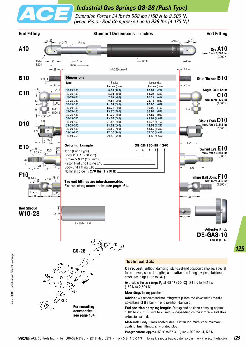
129
Issu
e 7.
2014
Spe
cific
atio
ns s
ubje
ct to
cha
nge
129
ACE Controls Inc. · Tel. 800-521-3320 · (248) 476-0213 · Fax (248) 476-2470 · E-mail: [email protected] · www.acecontrols.com
Industrial Gas Springs GS-28 (Push Type) Extension Forces 34 lbs to 562 lbs (150 N to 2,500 N) [when Piston Rod Compressed up to 939 lbs (4,175 N)]
End Fitting End FittingStandard Dimensions – inches
.47
1.57
.39
.79
.39
.47 1.57
.79
.47
M10x1.5
1.38
.71
.67
.98 L+/- 0.08 extended
.55
.32
StrokeRadiusR0.35
.47 thick
.98
.47 thick
1.10 .67
L = Stroke + 1.57
1.26
1.38M10x1.5
.63
.94 .63
18
.79
36°
Ø
Ø Ø
Ø Ø
Ø
1.69
1.69
Ø
Ø
Ø
.47
.32
24° .59 .39
.35
.71
.75
.28
.55 1.69.63
ØØØ
.751.69
AF .67
.98
45°M10x1.5 AF .67
DimensionsType
Stroke inches (mm)
L extended inches (mm)
GS-28-100 3.94 (100) 10.31 (262)GS-28-150 5.91 (150) 14.25 (362)GS-28-200 7.87 (200) 18.19 (462)GS-28-250 9.84 (250) 22.13 (562)GS-28-300 11.81 (300) 26.06 (662)GS-28-350 13.78 (350) 30.00 (762)GS-28-400 15.75 (400) 33.94 (862)GS-28-450 17.72 (450) 37.87 (962)GS-28-500 19.69 (500) 41.81 (1,062)GS-28-550 21.65 (550) 45.75 (1,162)GS-28-600 23.62 (600) 49.69 (1,262)GS-28-650 25.59 (650) 53.62 (1,362)GS-28-700 27.56 (700) 57.56 (1,462)GS-28-750 29.53 (750) 61.50 (1,562)
Ordering Example GS-28-150-EE-1200Type (Push Type)Body � 1.1" (28 mm)Stroke 5.91" (150 mm)Piston Rod End Fitting E10Body End Fitting E10Nominal Force F1 270 lbs (1,200 N)
The end fittings are interchangeable. For mounting accessories see page 164.
Technical DataOn request: Without damping, standard end position damping, special force curves, special lengths, alternative end fittings, wiper, stainless steel (see pages 135 to 147).Available force range F1 at 68 °F (20 °C): 34 lbs to 562 lbs (150 N to 2,500 N)Mounting: In any positionAdvice: We recommend mounting with piston rod downwards to take advantage of the built-in end position damping.End position damping length: Strong end position damping approx. 1.18" to 2.76" (30 mm to 70 mm) – depending on the stroke – and slow extension speed.Material: Body: Black coated steel. Piston rod: With wear-resistant coating. End fittings: Zinc plated steel.Progression: Approx. 58 % to 67 %, F2 max. 939 lbs (4,175 N)
A10 Eye A10 max. force 2,248 lbs
(10,000 N)
B10 Stud Thread B10
C10 Angle Ball Joint C10
max. force 405 lbs(1,800 N)
D10 Clevis Fork D10 max. force 2,248 lbs
(10,000 N)
E10 Swivel Eye E10 max. force 2,248 lbs
(10,000 N)
F10 Inline Ball Joint F10 max. force 405 lbs
(1,800 N)
Rod ShroudW10-28
GS-28
For mounting accessories see page 164.
Adjuster KnobDE-GAS-10
See page 119.

130
Issu
e 7.
2014
Spe
cific
atio
ns s
ubje
ct to
cha
nge
130
ACE Controls Inc. · Tel. 800-521-3320 · (248) 476-0213 · Fax (248) 476-2470 · E-mail: [email protected] · www.acecontrols.com
Industrial Gas Springs GS-40 (Push Type) Extension Forces 112 lbs to 1,124 lbs (500 N to 5,000 N) [when Piston Rod Compressed up to 1,675 lbs (7,450 N)]
End Fitting End FittingStandard Dimensions – inches
.59
2.2
.55
1.06
.55
.63 2.2
1.06
.59
M14x1.5
1.77
.98
.83
1.57 L+/- 0.08 extended
.79
.56
StrokeRadiusR0.49
.55 thick
1.57
.55 thick
1.57 .83
L = Stroke + 1.57
1.77
1.77M14x1.5
.79
1.18 .87
.98
1.1
36°
Ø
Ø Ø
Ø Ø
Ø
2.24
2.2
Ø
Ø
Ø
.59
.56
30° .79 .55
.75
1.18
1.02
.51
.71 2.24.71
ØØØ
.71.22
AF .94
1.57
30°M14x1.5 AF .87
DimensionsType
Stroke inches (mm)
L extended inches (mm)
GS-40-100 3.94 (100) 12.48 (317)GS-40-150 5.91 (150) 16.42 (417)GS-40-200 7.87 (200) 20.35 (517)GS-40-300 11.81 (300) 28.23 (717)GS-40-400 15.75 (400) 36.10 (917)GS-40-500 19.69 (500) 43.98 (1,117)GS-40-600 23.62 (600) 51.85 (1,317)GS-40-800 31.50 (800) 67.60 (1,717)GS-40-1000 39.37 (1,000) 83.35 (2,117)
Ordering Example GS-40-150-DD-3500Type (Push Type)Body � 1.57" (40 mm)Stroke 5.91" (150 mm)Piston Rod End Fitting D14Body End Fitting D14Nominal Force F1 787 lbs (3,500 N)
The end fittings are interchangeable. For mounting accessories see page 165.
Technical DataOn request: Without damping, standard end position damping, special force curves, special lengths, alternative end fittings, wiper, stainless steel (see pages 135 to 147).Available force range F1 at 68 °F (20 °C): 112 lbs to 1,124 lbs (500 N to 5,000 N)Mounting: In any positionAdvice: We recommend mounting with piston rod downwards to take advantage of the built-in end position damping.End position damping length: Strong end position damping approx. 30 to 70 mm (depending on the stroke) and slow extension speed.Material: Body: Black coated steel. Piston rod: With wear-resistant coating. End fittings: Zinc plated steel.Progression: Approx. 37 % to 49 %, F2 max. 1,675 lbs (7,450 N)
A14 Eye A14 max. force 2,248 lbs
(10,000 N)
B14 Stud Thread B14
C14 Angle Ball Joint C14
max. force 719 lbs (3,200 N)
D14 Clevis Fork D14 max. force 2,248 lbs
(10,000 N)
E14 Swivel Eye E14 max. force 2,248 lbs
(10,000 N)
F14 Inline Ball Joint F14 max. force 719 lbs
(3,200 N)
Rod ShroudW14-40
GS-40
For mounting accessories see page 165.
Adjuster KnobDE-GAS-14
See page 119.

131
Issu
e 7.
2014
Spe
cific
atio
ns s
ubje
ct to
cha
nge
131
ACE Controls Inc. · Tel. 800-521-3320 · (248) 476-0213 · Fax (248) 476-2470 · E-mail: [email protected] · www.acecontrols.com
Industrial Gas Springs GS-70 (Push Type) Extension Forces 450 lbs to 2,923 lbs (2,000 N to 13,000 N)[when Piston Rod Compressed up to 3,653 lbs (16,250 N)]
End Fitting End FittingStandard Dimensions – inches
1.38 L+/- 0.08 extended
1.18
Stroke1.38
2.76
L = Stroke + 5.12
3.15
ØØ
3.7
.98
1.97
.98
1.26 3.98
1.97
Ø
Ø
3.98
30° 1.34 .98
1.22
1.57
1.65
.87
1.18 3.71.18
ØØØ
M24x2
DimensionsType
Stroke inches (mm)
L extended inches (mm)
GS-70-100 3.94 (100) 12.60 (320)GS-70-200 7.87 (200) 20.47 (520)GS-70-300 11.81 (300) 28.35 (720)GS-70-400 15.75 (400) 36.22 (920)GS-70-500 19.69 (500) 44.09 (1,120)GS-70-600 23.62 (600) 51.97 (1,320)GS-70-700 27.56 (700) 59.84 (1,520)GS-70-800 31.50 (800) 67.72 (1,720)
Ordering Example GS-70-200-EE-8000Type (Push Type)Body � 2.76" (70 mm)Stroke 7.87" (200 mm)Piston Rod End Fitting E24Body End Fitting E24Nominal Force F1 1,798 lbs (8,000 N)
The end fittings are interchangeable. For mounting accessories see page 165. Standard gas spring with valve.
Technical DataOn request: Without damping, special force curves, special lengths, alternative end fittings, wiper, stainless steel.Available force range F1 at 68 °F (20 °C): 450 lbs to 2,923 lbs (2,000 N to 13,000 N)Mounting: In any positionAdvice: We recommend mounting with piston rod downwards to take advantage of the built-in end position damping.End position damping length: Approx. 0.39" (10 mm)Material: Body: Black coated steel or zinc plated steel. Piston rod: With wear-resistant coating. End fittings: Zinc plated steel.Progression: Approx. 25 %, F2 max. 3,653 lbs (16,250 N)
B24 Stud Thread B24
D24 Clevis Fork D24 max. force 11,240 lbs
(50,000 N)
E24 Swivel Eye E24 max. force 11,240 lbs
(50,000 N)
Rod ShroudW24-70
GS-70
For mounting accessories see page 165.

132
Issu
e 7.
2014
Spe
cific
atio
ns s
ubje
ct to
cha
nge
132
Tandem Gas Springs GST-40
ACE offers tandem gas springs specially for heavy flaps and hoods with a large opening angle. These are characterised by a high initial force and low end force. The tandem gas springs have two pressure tubes with different extension forces and progression curves, and are therefore able to cover two force ranges. The tandem gas springs are designed individually according to their use – free of charge by the ACE calculation service. They are manufactured especially for your application. The force ranges are aligned precisely to each other and are adjusted to the required kinematics. Tandem gas springs are maintenance free and ready for installation. ACE tandem gas springs offer the best service life based on a piston rod with a hard wearing surface coating as well as an integrated grease chamber, which ensures constant lubrication of the seals. A comprehensive range of fitting parts ensures easy installation.
Operating fluid: Nitrogen gas and oilMaterial: Piston rod: With wear-resistant coating. Bodies and end fittings: Zinc plated steel.Mounting: According to calculation. Please adopt the mounting points determined by ACE.Operating temperature range: -4 °F to 176 °FOn request: Material AISI 304/303 (V2A) and material AISI 316L/316Ti (V4A).
Filled with High Pressure Nitrogen Gas
Metering Orifice forControlled Extension and Compression Velocities
Oil Zone for End Position Damping
Integral Grease Chamber for Increased Lifetime
Main Bearing
Piston Rod with Wear-Resistant Coating
Body A
Body B
Precision Steel Tube
Gas Valve
“Reduce the need for muscle power for comfortably opening
heavy flaps!”

133
Issu
e 7.
2014
Spe
cific
atio
ns s
ubje
ct to
cha
nge
133
ACE Controls Inc. · Tel. 800-521-3320 · (248) 476-0213 · Fax (248) 476-2470 · E-mail: [email protected] · www.acecontrols.com
End Fitting End FittingStandard Dimensions – inches
2.2
.55
1.06
.55
.63 2.2
1.06
.59
M14x1.5
.98
.83
1.57 L +/- 0.08 extended
.56
RadiusR0.49
.55 thick
1.57
.55 thick
.83
Ø
Ø
2.24
Ø Ø
.59
.56
30° .79 .55
.75
1.18
1.02
.51
.71 2.24.71
ØØØ
Body AØ 1.57
Body BØ 1.57Stroke BStroke A
.79Ø
Tandem Gas Springs GST-40Extension Forces 67 lbs to 1,124 lbs (300 N to 5,000 N)
DimensionsType
Stroke A inches (mm)
Stroke B inches (mm)
L extended inches (mm)
GST-40-50-100 1.97 (50) 3.94 (100) 10.09 (485)GST-40-50-150 1.97 (50) 5.91 (150) 23.03 (585)GST-40-50-200 1.97 (50) 7.87 (200) 26.97 (685)GST-40-70-250 2.76 (70) 9.84 (250) 32.48 (825)GST-40-70-300 2.76 (70) 11.81 (300) 36.42 (925)GST-40-70-350 2.76 (70) 13.78 (350) 40.35 (1,025)GST-40-70-400 2.76 (70) 15.75 (400) 40.35 (1,125)
Ordering Example GST-40-50-150-AD-900N-2500NType (Tandem Gas Spring)Body � 1.57" (40 mm)Stroke A 1.97" (50 mm)Stroke B 5.91" (150 mm)Body A End Fitting, A14Body B End Fitting, D14Nominal Force Body A, 202 lbs (900 N)Nominal Force Body B, 562 lbs (2 ,500 N)
The end fittings are interchangeable. These gas springs are tailored to the relevant application and are therefore not available ex stock. For mounting accessories see page 165.
A14
ME14
D14
E14
ND14
ME14
Technical DataOn request: Without damping, standard end position damping, special force curves, special lengths, alternative end fittings, wiper.Available force range F1 at 68 °F (20 °C): 67 lbs to 1,124 lbs (300 N to 5,000 N)Mounting: According to calculation. Please adopt the mounting points determined by ACE.End position damping length: Application-specific end position damping and extension speed.Material: Piston rod: With wear-resistant coating. Bodies and end fittings: Zinc plated steel.Progression: According to calculation relating to your application.
A14 Eye A14 max. force 2,248 lbs
(10,000 N)
B14 Stud Thread B14
D14 Clevis Fork D14 max. force 2,248 lbs
(10,000 N)
E14 Swivel Eye E14 max. force 2,248 lbs
(10,000 N)
GST-40
For mounting accessories see page 165.

134
Issu
e 7.
2014
Spe
cific
atio
ns s
ubje
ct to
cha
nge
134
Stainless Steel Industrial Gas Springs (Push Type)
Stainless steel gas springs (push type)Material AISI 304/303 (V2A), Material AISI 316L/316Ti (V4A)
In addition to the comprehensive range of in- dustrial gas springs with valve, ACE also offers a wide range of industrial gas springs made of stainless steel with body diameters from .31" to 2.76". This high-quality version is also available on request in all stroke lengths and possible extension forces. The comprehensive range of fitting parts ensures easy installation and makes the gas springs universal in use. Stainless steel industrial gas springs are used everywhere that raising and lowering is required. The standard type is filled with a special oil that conforms to the requirements FDA 21 CFR 178.3570 of the food industry. Due to their special properties, non-rusting and low magnetism, they are the preferred equipment for medical and clean-room tech- nology, the foodstuffs industry, electronics and shipbuilding sector.
Operating fluid: Nitrogen gas and HLP oil according to DIN 51 524, part 2Material: Piston rod, body and end fittings: Material AISI 304/303 (V2A) or material AISI 316L/316Ti (V4A).Mounting: We recommend mounting with piston rod downwards to take advantage of the built-in end position damping.Operating temperature range: -4 °F to 176 °F On request: Without damping, strong end position damping, special force curves, wiper, special lengths, alternative end fittings.
Rear End Cap in Stainless Steel
Stainless Steel Body
Front Bearing in Brass
Stainless Steel Piston Rod
Gas Valve
Oil Zone for End Position Damping and Lubrication (recommended mounting position: piston rod downwards)
Metering Orifice for Controlled Extension and Compression Velocities
“NEW: Standard type with special oil suited for
the food industry and available in many sizes ex stock!”

135
Issu
e 7.
2014
Spe
cific
atio
ns s
ubje
ct to
cha
nge
135
ACE Controls Inc. · Tel. 800-521-3320 · (248) 476-0213 · Fax (248) 476-2470 · E-mail: [email protected] · www.acecontrols.com
.63
.16
.31
.16
.20 .63
.31
Ø
.71.71
.16
.51 .31
.24.31
.71
ØØ
Ø
.71M4x0.7
.33
.51 .31
.24
.39
36°
Ø Ø
.43
.31
.43
.16
.24
.31Ø
RadiusR0.16
.16 thick
End Fitting End FittingStandard Dimensions – inches
.20
M3.5x0.6
.20 L +/- 0.08 extended
.12
Stroke.20
.31Ø Ø
Stainless Steel Gas Springs GS-8-V4A (Push Type) Extension Forces 6 lbs to 22 lbs (25 N to 100 N) [when Piston Rod Compressed up to 29 lbs (130 N)]
DimensionsType
Stroke inches (mm)
L extended inches (mm)
GS-8-20-V4A 0.79 (20) 2.83 (72)GS-8-30-V4A 1.18 (30) 3.62 (92)GS-8-40-V4A 1.57 (40) 4.41 (112)GS-8-50-V4A 1.97 (50) 5.20 (132)GS-8-60-V4A 2.36 (60) 5.98 (152)GS-8-80-V4A 3.14 (80) 7.56 (192)
Ordering Example GS-8-30-AC-30-V4AType (Push Type)Body � 0.31" (8 mm)Stroke 1.18" (30 mm)Piston Rod End Fitting A3.5-V4A Body End Fitting C3.5-V4ANominal Force F1 7 lbs (30 N)Indicated by K.-No. on delivery
The end fittings are interchangeable. For mounting accessories see page 166.
A3.5-V4A
C3.5-V4A
NA3.5-V4A
A3.5-V4A
NG3.5-V4A
OG3.5-V4A
OA3.5-V4A
D3.5-V4A
G3.5-V4A
Technical DataOn request: Without damping, strong end position damping, special force curves, special end fittings.Available force range F1 at 68 °F (20 °C): 6 lbs to 22 lbs (25 N to 100 N)Mounting: We recommend mounting with piston rod downwards to take advantage of the built-in end position damping.End position damping length: Approx. 0.2" (5 mm)Material: Piston rod, body and end fittings: Material AISI 316L/316Ti (V4A).Progression: Approx. 27 %, F2 max. 29 lbs (130 N)
B3.5 Stud Thread B3.5
A3.5-V4A Eye A3.5-V4A
max. force 83 lbs (370 N)
C3.5-V4A Angle Ball Joint C3.5-V4A
max. force 83 lbs (370 N)
D3.5-V4A Clevis Fork D3.5-V4A
max. force 83 lbs (370 N)
G3.5-V4A Ball Socket G3.5-V4A
max. force 83 lbs (370 N)
GS-8-V4A
For mounting accessories see page 166.
Adjuster Knob DE-GAS-3.5
See page 119.

136
Issu
e 7.
2014
Spe
cific
atio
ns s
ubje
ct to
cha
nge
136
ACE Controls Inc. · Tel. 800-521-3320 · (248) 476-0213 · Fax (248) 476-2470 · E-mail: [email protected] · www.acecontrols.com
Stainless Steel Gas Springs GS-10-V4A (Push Type) Extension Forces 7 lbs to 22 lbs (30 N to 100 N) [when Piston Rod Compressed up to 26 lbs (115 N)]
.63
.16
.31
.16
.20 .63
.31
Ø
.71.71
.16
.51 .31
.24.31
.71
ØØ
Ø
.71M4x0.7
.33
.51 .31
.24
.39
36°
Ø Ø
.43
.31
.43
.16
.24
.31Ø
RadiusR0.16
.16 thick
End Fitting End FittingStandard Dimensions – inches
.20
M3.5x0.6
.20 L +/- 0.08 extended
.12
Stroke.20
.39Ø Ø
DimensionsType
Stroke inches (mm)
L extended inches (mm)
GS-10-20-V4A 0.79 (20) 2.83 (72)GS-10-30-V4A 1.18 (30) 3.62 (92)GS-10-40-V4A 1.57 (40) 4.41 (112)GS-10-50-V4A 1.97 (50) 5.20 (132)GS-10-60-V4A 2.36 (60) 5.98 (152)GS-10-80-V4A 3.14 (80) 7.56 (192)
Ordering Example GS-10-30-AC-30-V4AType (Push Type)Body � 0.39" (10 mm)Stroke 1.18" (30 mm)Piston Rod End Fitting A3.5-V4A Body End Fitting C3.5-V4ANominal Force F1 7 lbs (30 N)Indicated by K.-No. on delivery
The end fittings are interchangeable. For mounting accessories see page 166.
Technical DataOn request: Without damping, strong end position damping, special force curves, special end fittings.Available force range F1 at 68 °F (20 °C): 7 lbs to 22 lbs (30 N to 100 N)Mounting: We recommend mounting with piston rod downwards to take advantage of the built-in end position damping.End position damping length: Approx. 0.2" (5 mm)Material: Piston rod, body and end fittings: Material AISI 316L/316Ti (V4A).Progression: Approx. 12 %, F2 max. 26 lbs (115 N)
B3.5 Stud Thread B3.5
A3.5-V4A Eye A3.5-V4A
max. force 83 lbs (370 N)
C3.5-V4A Angle Ball Joint C3.5-V4A
max. force 83 lbs (370 N)
D3.5-V4A Clevis Fork D3.5-V4A
max. force 83 lbs (370 N)
G3.5-V4A Ball Socket G3.5-V4A
max. force 83 lbs (370 N)
GS-10-V4A
For mounting accessories see page 166.
Adjuster Knob DE-GAS-3.5
See page 119.
A3.5-V4A
C3.5-V4A
NA3.5-V4A
A3.5-V4A
NG3.5-V4A
OG3.5-V4A
OA3.5-V4A
D3.5-V4A
G3.5-V4A

137
Issu
e 7.
2014
Spe
cific
atio
ns s
ubje
ct to
cha
nge
137
ACE Controls Inc. · Tel. 800-521-3320 · (248) 476-0213 · Fax (248) 476-2470 · E-mail: [email protected] · www.acecontrols.com
Stainless Steel Gas Springs GS-12-V4A (Push Type) Extension Forces 6 lbs to 45 lbs (25 N to 200 N) [when Piston Rod Compressed up to 53 lbs (235 N)]
.63
.16
.31
.16
.20 .63
.31
Ø
.71.71
.16
.51 .31
.24.31
.71
ØØ
Ø
.71M4x0.7
.33
.51 .31
.24
.39
36°
Ø Ø
.43
.31
.43
.16
.24
.31Ø
RadiusR0.16
.16 thick
End Fitting End FittingStandard Dimensions – inches
.20
M3.5x0.6
.20 L +/- 0.08 extended
.16
Stroke.20
.47Ø Ø
DimensionsType
Stroke inches (mm)
L extended inches (mm)
GS-12-20-V4A 0.79 (20) 2.83 (72)GS-12-30-V4A 1.18 (30) 3.62 (92)GS-12-40-V4A 1.57 (40) 4.41 (112)GS-12-50-V4A 1.97 (50) 5.20 (132)GS-12-60-V4A 2.36 (60) 5.98 (152)GS-12-80-V4A 3.14 (80) 7.56 (192)GS-12-100-V4A 3.94 (100) 9.13 (232)GS-12-120-V4A 4.72 (120) 10.71 (272)GS-12-150-V4A 5.91 (150) 13.07 (332)
Ordering Example GS-12-100-AA-30-V4AType (Push Type)Body � 0.47" (12 mm)Stroke 3.94" (100 mm)Piston Rod End Fitting A3.5-V4A Body End Fitting A3.5-V4ANominal Force F1 7 lbs (30 N)Indicated by K.-No. on delivery
The end fittings are interchangeable. For mounting accessories see page 166.
Technical DataOn request: Without damping, strong end position damping, special force curves, special end fittings.Available force range F1 at 68 °F (20 °C): 6 lbs to 45 lbs (25 N to 200 N)Mounting: We recommend mounting with piston rod downwards to take advantage of the built-in end position damping.End position damping length: Approx. 0.39" (10 mm)Material: Piston rod, body and end fittings: Material AISI 316L/316Ti (V4A).Progression: Approx. 18 %, F2 max. 53 lbs (235 N)
B3.5 Stud Thread B3.5
A3.5-V4A Eye A3.5-V4A
max. force 83 lbs (370 N)
C3.5-V4A Angle Ball Joint C3.5-V4A
max. force 83 lbs (370 N)
D3.5-V4A Clevis Fork D3.5-V4A
max. force 83 lbs (370 N)
G3.5-V4A Ball Socket G3.5-V4A
max. force 83 lbs (370 N)
GS-12-V4A
For mounting accessories see page 166.
Adjuster Knob DE-GAS-3.5
See page 119.
A3.5-V4A
C3.5-V4A
NA3.5-V4A
A3.5-V4A
NG3.5-V4A
OG3.5-V4A
OA3.5-V4A
D3.5-V4A
G3.5-V4A

138
Issu
e 7.
2014
Spe
cific
atio
ns s
ubje
ct to
cha
nge
138
ACE Controls Inc. · Tel. 800-521-3320 · (248) 476-0213 · Fax (248) 476-2470 · E-mail: [email protected] · www.acecontrols.com
Stainless Steel Gas Springs GS-15-V4A (Push Type) Extension Forces 9 lbs to 90 lbs (40 N to 400 N) [when Piston Rod Compressed up to 120 lbs (535 N)]
End Fitting End FittingStandard Dimensions – inches
.28
.87.87
.18
.51 .31
.47.31
M5x0.8
.87
.28 L+/- 0.08 extended
.24
Stroke.28
.61
L = Stroke + 0.79
.75
ØØ
Ø
Ø Ø
1.06
Ø
.87M5x0.8
.31
.51 .31
.47
.39
36°
Ø Ø
.79
.63
24° .39 .20
.31
.47
.51
.18
.39 1.06.47
ØØ
Ø
.20
.39
.20
.24 .79
.39
Ø
.55
.35
.63
.24
.31
.39Ø
RadiusR0.2
.24 thickDimensionsType
Stroke inches (mm)
L extended inches (mm)
GS-15-20-V4A 0.79 (20) 2.91 (74)GS-15-40-V4A 1.57 (40) 4.49 (114)GS-15-50-V4A 1.97 (50) 5.28 (134)GS-15-60-V4A 2.36 (60) 6.06 (154)GS-15-80-V4A 3.15 (80) 7.64 (194)GS-15-100-V4A 3.94 (100) 9.21 (234)GS-15-120-V4A 4.72 (120) 10.79 (274)GS-15-150-V4A 5.91 (150) 13.15 (334)
Ordering Example GS-15-150-AC-150-V4AType (Push Type)Body � 0.61" (15.6 mm)Stroke 5.91" (150 mm)Piston Rod End Fitting A5-V4ABody End Fitting C5-V4ANominal Force F1 34 lbs (150 N)Indicated by K.-No. on delivery
The end fittings are interchangeable. For mounting accessories see page 166. Strokes also available up to 11.81" (300 mm).
Technical DataOn request: Without damping, strong end position damping, special force curves, special lengths, alternative end fittings and wiper.Available force range F1 at 68 °F (20 °C): 9 lbs to 90 lbs (40 N to 400 N)Mounting: We recommend mounting with piston rod downwards to take advantage of the built-in end position damping.End position damping length: Approx. 0.79" (20 mm) depending on the stroke.Material: Piston rod, body and end fittings: Material AISI 316L/316Ti (V4A).Progression: Approx. 34 %, F2 max. 120 lbs (535 N)
B5 Stud Thread B5
A5-V4A Eye A5-V4A max. force 110 lbs
(490 N)
C5-V4AAngle Ball Joint
C5-V4A max. force 97 lbs
(430 N)
D5-V4A Clevis Fork D5-V4A max. force 110 lbs
(490 N)
G5-V4A
Swivel Eye E5-V4A max. force 110 lbs
(490 N)
Adjuster Knob DE-GAS-5
See page 119.
A5-V4A
MA5-V4A
NG5-V4A
NA5-V4A
OG5-V4A
OA5-V4A
PA5-V4A
PG5-V4A
C5-V4AD5-V4A
E5-V4AG5-V4A
GS-15-V4A
Rod Shroud W5-15-V4A
E5-V4A
Ball Socket G5-V4A max. force 97 lbs
(430 N)
For mounting accessories see page 166.

139
Issu
e 7.
2014
Spe
cific
atio
ns s
ubje
ct to
cha
nge
139
ACE Controls Inc. · Tel. 800-521-3320 · (248) 476-0213 · Fax (248) 476-2470 · E-mail: [email protected] · www.acecontrols.com
Stainless Steel Gas Springs GS-19-V4A (Push Type) Extension Forces 11 lbs to 157 lbs (50 N to 700 N) [when Piston Rod Compressed up to 209 lbs (930 N)]
End Fitting End FittingStandard Dimensions – inches
.39
1.181.18
.24
.79 .51
.59.51
M8x1.25
1.18
.39 L+/- 0.08 extended
.31
Stroke.39
.75
L = Stroke + 1.18
.91
ØØ
Ø
Ø Ø
1.42
Ø
1.18M8x1.25
.47
.79 .51
.59
.65
36°
Ø Ø
1.26
.75
24° .47 .31
.47
.63
.63
.24
.47 1.42.51
ØØ
Ø
.31
.63
.31
.39 1.26
.63
Ø
.87
.45
.75
.32
.39
.55Ø
RadiusR0.28
.39 thick
Technical DataOn request: Without damping, strong end position damping, special force curves, special lengths, alternative end fittings and wiper.Available force range F1 at 68 °F (20 °C): 11 lbs to 157 lbs (50 N to 700 N)Mounting: We recommend mounting with piston rod downwards to take advantage of the built-in end position damping.End position damping length: Approx. 0.79" (20 mm) depending on the stroke.Material: Piston rod, body and end fittings: Material AISI 316L/316Ti (V4A).Progression: Approx. 33 %, F2 max. 209 lbs (930 N)
A8-V4A
MA8-V4A
MA8-V4A
NG8-V4A
NA8-V4A
OG8-V4A
OA8-V4A
PA8-V4A
PG8-V4A
C8-V4AD8-V4A
E8-V4AG8-V4A
DimensionsType
Stroke inches (mm)
L extended inches (mm)
GS-19-50-V4A 1.97 (50) 6.46 (164)GS-19-100-V4A 3.94 (100) 10.39 (264)GS-19-150-V4A 5.91 (150) 14.33 (364)GS-19-200-V4A 7.87 (200) 18.27 (464)GS-19-250-V4A 9.84 (250) 22.20 (564)GS-19-300-V4A 11.81 (300) 26.14 (664)
Ordering Example GS-19-150-AC-600-V4AType (Push Type)Body � 0.75" (19 mm)Stroke 5.91" (150 mm)Piston Rod End Fitting A8-V4ABody End Fitting C8-V4ANominal Force F1 135 lbs (600 N)Indicated by K.-No. on delivery
The end fittings are interchangeable. Strokes also available up to 19.69" (500 mm). For mounting accessories see page 167.
B8 Stud Thread B8
A8-V4A Eye A8-V4A max. force 351 lbs
(1,560 N)
C8-V4AAngle Ball Joint
C8-V4A max. force 256 lbs
(1,140 N)
D8-V4A Clevis Fork D8-V4A max. force 351 lbs
(1,560 N)
E8-V4ASwivel Eye E8-V4A
max. force 351 lbs(1,560 N)
G8-V4A Ball Socket G8-V4A max. force 256 lbs
(1,140 N)
Rod Shroud W8-19-V4A
Adjuster Knob DE-GAS-8
See page 119.GS-19-V4A
For mounting accessories see page 167.

140
Issu
e 7.
2014
Spe
cific
atio
ns s
ubje
ct to
cha
nge
140
ACE Controls Inc. · Tel. 800-521-3320 · (248) 476-0213 · Fax (248) 476-2470 · E-mail: [email protected] · www.acecontrols.com
Stainless Steel Gas Springs GS-22-V4A (Push Type) Extension Forces 22 lbs to 270 lbs (100 N to 1,200 N) [when Piston Rod Compressed up to 356 lbs (1,585 N)]
End Fitting End FittingStandard Dimensions – inches
10
301.18
.24
.79 .51
.59.51
M8x1.25
30
.39 L+/- 0.08 extended
.39
Stroke.39
.91
L = Stroke + 1.18
1.10
ØØ
Ø
Ø Ø
36
Ø
1.18M8x1.25
.47
.79 .51
.59
.65
36°
Ø Ø
32
19
24° .47 .31
.47
.63
.63
.24
.47 1.42.51
ØØ
Ø
.31
.63
.31
.39 1.26
.63
Ø
.87
.45
.75
.32
.39
.55Ø
RadiusR0.28
.39 thick
Technical DataOn request: Without damping, strong end position damping, special force curves, special lengths, alternative end fittings and wiper.Available force range F1 at 68 °F (20 °C): 22 lbs to 270 lbs (100 N to 1,200 N)Mounting: We recommend mounting with piston rod downwards to take advantage of the built-in end position damping.End position damping length: Approx. 0.79" (20 mm) depending on the stroke.Material: Piston rod, body and end fittings: Material AISI 316L/316Ti (V4A).Progression: Approx. 32 %, F2 max. 356 lbs (1,585 N)
A8-V4A
MA8-V4A
MA8-V4A
NG8-V4A
NA8-V4A
OG8-V4A
OA8-V4A
PA8-V4A
PG8-V4A
C8-V4AD8-V4A
E8-V4AG8-V4A
DimensionsType
Stroke inches (mm)
L extended inches (mm)
GS-22-50-V4A 1.97 (50) 6.46 (164)GS-22-100-V4A 3.94 (100) 10.39 (264)GS-22-150-V4A 5.91 (150) 14.33 (364)GS-22-200-V4A 7.87 (200) 18.28 (464)GS-22-250-V4A 9.84 (250) 22.20 (564)GS-22-300-V4A 11.81 (300) 26.14 (664)GS-22-350-V4A 13.78 (350) 30.08 (764)GS-22-400-V4A 15.75 (400) 34.02 (864)GS-22-450-V4A 17.72 (450) 37.95 (964)GS-22-500-V4A 19.69 (500) 41.89 (1,064)GS-22-550-V4A 21.65 (550) 45.83 (1,164)GS-22-600-V4A 23.62 (600) 49.76 (1,264)GS-22-650-V4A 25.59 (650) 53.70 (1,364)GS-22-700-V4A 27.56 (700) 57.64 (1,464)
Ordering Example GS-22-150-AE-800-V4AType (Push Type)Body � 0.91" (23 mm)Stroke 5.91" (150 mm)Piston Rod End Fitting A8-V4ABody End Fitting E8-V4ANominal Force F1 180 lbs (800 N)Indicated by K.-No. on delivery
The end fittings are interchangeable. For mounting accessories see page 167.
B8 Stud Thread B8
A8-V4A Eye A8-V4A max. force 351 lbs
(1,560 N)
C8-V4AAngle Ball Joint
C8-V4A max. force 256 lbs
(1,140 N)
D8-V4A Clevis Fork D8-V4A max. force 351 lbs
(1,560 N)
E8-V4ASwivel Eye E8-V4A
max. force 351 lbs(1,560 N)
G8-V4A Ball Socket G8-V4A max. force 256 lbs
(1,140 N)
Rod Shroud W8-22-V4A
Adjuster Knob DE-GAS-8
See page 119.GS-22-V4A
For mounting accessories see page 167.
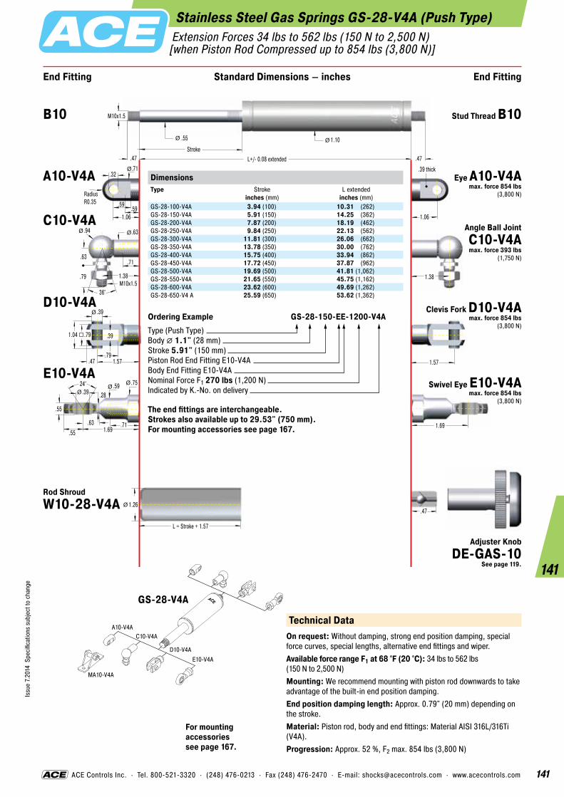
141
Issu
e 7.
2014
Spe
cific
atio
ns s
ubje
ct to
cha
nge
141
ACE Controls Inc. · Tel. 800-521-3320 · (248) 476-0213 · Fax (248) 476-2470 · E-mail: [email protected] · www.acecontrols.com
Stainless Steel Gas Springs GS-28-V4A (Push Type) Extension Forces 34 lbs to 562 lbs (150 N to 2,500 N) [when Piston Rod Compressed up to 854 lbs (3,800 N)]
End Fitting End FittingStandard Dimensions – inches
.47
M10x1.5
1.38
.47 L+/- 0.08 extended
.55
Stroke.47
1.10
L = Stroke + 1.57
1.26
Ø Ø
1.69
Ø
1.38M10x1.5
.63
.94 .63
.71
.79
36°
Ø Ø
1.57
1.06
24° .59 .39
.55
.71
.75
.28
.55 1.69.63
ØØ
Ø
.39
.79
.39
.47 1.57
.79
Ø
1.04
.59
1.06
.32
.59
.71Ø
RadiusR0.35
.39 thick
Ordering Example GS-28-150-EE-1200-V4AType (Push Type)Body � 1.1" (28 mm)Stroke 5.91" (150 mm)Piston Rod End Fitting E10-V4ABody End Fitting E10-V4ANominal Force F1 270 lbs (1,200 N)Indicated by K.-No. on delivery
The end fittings are interchangeable. Strokes also available up to 29.53" (750 mm). For mounting accessories see page 167.
Technical DataOn request: Without damping, strong end position damping, special force curves, special lengths, alternative end fittings and wiper.Available force range F1 at 68 °F (20 °C): 34 lbs to 562 lbs (150 N to 2,500 N)Mounting: We recommend mounting with piston rod downwards to take advantage of the built-in end position damping.End position damping length: Approx. 0.79" (20 mm) depending on the stroke.Material: Piston rod, body and end fittings: Material AISI 316L/316Ti (V4A).Progression: Approx. 52 %, F2 max. 854 lbs (3,800 N)
A10-V4AC10-V4A
D10-V4AE10-V4A
MA10-V4A
GS-28-V4A
For mounting accessories see page 167.
B10 Stud Thread B10
A10-V4A Eye A10-V4A max. force 854 lbs
(3,800 N)
C10-V4A Angle Ball Joint C10-V4A max. force 393 lbs
(1,750 N)
D10-V4A Clevis Fork D10-V4A max. force 854 lbs
(3,800 N)
E10-V4ASwivel Eye E10-V4A
max. force 854 lbs(3,800 N)
Rod Shroud W10-28-V4A
Adjuster Knob DE-GAS-10
See page 119.
DimensionsType
Stroke inches (mm)
L extended inches (mm)
GS-28-100-V4A 3.94 (100) 10.31 (262)GS-28-150-V4A 5.91 (150) 14.25 (362)GS-28-200-V4A 7.87 (200) 18.19 (462)GS-28-250-V4A 9.84 (250) 22.13 (562)GS-28-300-V4A 11.81 (300) 26.06 (662)GS-28-350-V4A 13.78 (350) 30.00 (762)GS-28-400-V4A 15.75 (400) 33.94 (862)GS-28-450-V4A 17.72 (450) 37.87 (962)GS-28-500-V4A 19.69 (500) 41.81 (1,062)GS-28-550-V4A 21.65 (550) 45.75 (1,162)GS-28-600-V4A 23.62 (600) 49.69 (1,262)GS-28-650-V4 A 25.59 (650) 53.62 (1,362)

142
Issu
e 7.
2014
Spe
cific
atio
ns s
ubje
ct to
cha
nge
142
ACE Controls Inc. · Tel. 800-521-3320 · (248) 476-0213 · Fax (248) 476-2470 · E-mail: [email protected] · www.acecontrols.com
Stainless Steel Gas Springs GS-40-V4A (Push Type) Extension Forces 112 lbs to 1,124 lbs (500 N to 5,000 N) [when Piston Rod Compressed up to 1,574 lbs (7,000 N)]
End Fitting End FittingStandard Dimensions – inches
.59
M14x1.5
1.77
.59 L +/- 0.08 extended
.79Stroke
.59
1.57
L = Stroke + 1.57
1.77
Ø Ø
2.24
Ø
1.77M14x1.5
.79
1.18 .87
.98
1.1
36°
Ø Ø
2.20
1.65
30° .79 .55
.75
1.18
1.02
.51
.71 2.24.71
ØØ
Ø
.55
1.06
.55
.63 2.20
1.06
Ø
1.38
.77
1.65
.56
.71
.98Ø
RadiusR0.49
.55 thick
Technical DataOn request: Without damping, strong end position damping, special force curves, special lengths, alternative end fittings and wiper.Available force range F1 at 68 °F (20 °C): 112 lbs to 1,124 lbs (500 N to 5,000 N)Mounting: We recommend mounting with piston rod downwards to take advantage of the built-in end position damping.End position damping length: Approx. 2.24" (30 mm) depending on the strokeMaterial: Piston rod, body and end fittings: Material AISI 316L/316Ti (V4A).Progression: Approx. 40 %, F2 max. 1,574 lbs (7,000 N)
For mounting accessories see page 168.
A14-V4AC14-V4A
D14-V4AE14-V4A
ME14-VA
ME14-VA
ND14-VA
GS-40-V4A
B14 Stud Thread B14
A14-V4A
C14-V4A
D14-V4A
E14-V4A
Rod Shroud W14-40-V4A
Adjuster Knob DE-GAS-14
See page 119.
DimensionsType
Stroke inches (mm)
L extended inches (mm)
GS-40-100-V4A 3.94 (100) 12.48 (317)GS-40-150-V4A 5.91 (150) 16.42 (417)GS-40-200-V4A 7.87 (200) 20.35 (517)GS-40-300-V4A 11.81 (300) 28.23 (717)GS-40-400-V4A 15.75 (400) 36.10 (917)GS-40-500-V4A 19.69 (500) 43.98 (1,117)GS-40-600-V4A 23.62 (600) 51.85 (1,317)
Ordering Example GS-40-150-DD-3500-V4AType (Push Type)Body � 1.57" (40 mm)Stroke 5.91" (150 mm)Piston Rod End Fitting D14-V4ABody End Fitting D14-V4ANominal Force F1 787 lbs (3,500 N)Indicated by K.-No. on delivery
The end fittings are interchangeable. Strokes also available up to 39.37" (1,000 mm). For mounting accessories see page 168.
Eye A14-V4A max. force 1,574 lbs
(7,000 N)
Angle Ball Joint C14-V4A max. force 719 lbs
(3,200 N)
Clevis Fork D14-V4A max. force 1,574 lbs
(7,000 N)
Swivel Eye E14-V4A max. force 1,574 lbs
(7,000 N)

143
Issu
e 7.
2014
Spe
cific
atio
ns s
ubje
ct to
cha
nge
143
ACE Controls Inc. · Tel. 800-521-3320 · (248) 476-0213 · Fax (248) 476-2470 · E-mail: [email protected] · www.acecontrols.com
A5-VA
MA5-V4A
NG5-V4A
NA5-V4A
OG5-V4A
OA5-V4A
PA5-V4A
PG5-V4A
C5-VAD5-VA
E5-VAG5-VA
Stainless Steel Gas Springs GS-15-VA (Push Type) Extension Forces 9 lbs to 90 lbs (40 N to 400 N) [when Piston Rod Compressed up to 120 lbs (535 N)]
End Fitting End FittingStandard Dimensions – inches
.28
.87.87
.18
.51 .31
.47.31
M5x0.8
.87
.28 L+/- 0.08 extended
.24
Stroke.28
.61
L = Stroke + 0.79
.75
ØØ
Ø
Ø Ø
1.06
Ø
.87M5x0.8
.31
.51 .31
.47
.39
36°
Ø Ø
.79
.63
24° .39 .20
.31
.47
.51
.18
.39 1.06.47
ØØ
Ø
.20
.39
.20
.24 .79
.39
Ø
.55
.35
.63
.24
.31
.39Ø
RadiusR0.2
.24 thickDimensionsType
Stroke inches (mm)
L extended inches (mm)
GS-15-20-VA 0.79 (20) 2.91 (74)GS-15-40-VA 1.57 (40) 4.49 (114)GS-15-50-VA 1.97 (50) 5.28 (134)GS-15-60-VA 2.36 (60) 6.06 (154)GS-15-80-VA 3.15 (80) 7.64 (194)GS-15-100-VA 3.94 (100) 9.21 (234)GS-15-120-VA 4.72 (120) 10.79 (274)GS-15-150-VA 5.91 (150) 13.15 (334)
Ordering Example GS-15-150-AC-150-VAType (Push Type)Body � 0.61" (15.6 mm)Stroke 5.91" (150 mm)Piston Rod End Fitting A5-VABody End Fitting C5-VANominal Force F1 34 lbs (150 N)Indicated by K.-No. on delivery
The end fittings are interchangeable. For mounting accessories see page 166.
Technical DataOn request: Without damping, strong end position damping, special force curves, special lengths, alternative end fittings, wiper. Gas springs and accessories: Material AISI 316L/316Ti (V4A).Available force range F1 at 68 °F (20 °C): 9 lbs to 90 lbs (40 N to 400 N)Mounting: We recommend mounting with piston rod downwards to take advantage of the built-in end position damping.End position damping length: Approx. 0.79" (20 mm) depending on the strokeMaterial: Piston rod, body and end fittings: Material AISI 304/303 (V2A).Progression: Approx. 34 %, F2 max. 120 lbs (535 N)
B5 Stud Thread B5
A5-VA Eye A5-VA max. force 110 lbs
(490 N)
C5-VA Angle Ball Joint C5-VA
max. force 97 lbs(430 N)
D5-VA Clevis Fork D5-VA max. force 110 lbs
(490 N)
E5-VA Swivel Eye E5-VA max. force 110 lbs
(490 N)
G5-VA Ball Socket G5-VA max. force 97 lbs
(430 N)
Rod Shroud W5-15-VA
For mounting accessories see page 166.
GS-15-VA
Adjuster Knob DE-GAS-5
See page 119.
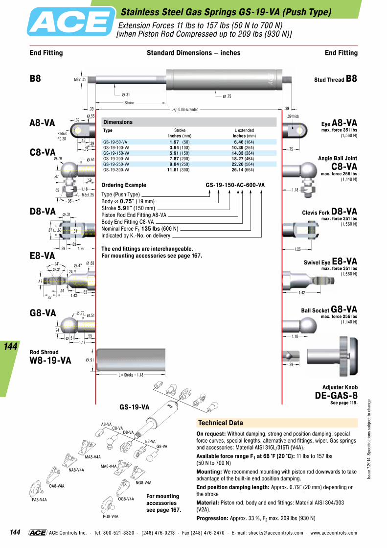
144
Issu
e 7.
2014
Spe
cific
atio
ns s
ubje
ct to
cha
nge
144
ACE Controls Inc. · Tel. 800-521-3320 · (248) 476-0213 · Fax (248) 476-2470 · E-mail: [email protected] · www.acecontrols.com
Stainless Steel Gas Springs GS-19-VA (Push Type) Extension Forces 11 lbs to 157 lbs (50 N to 700 N) [when Piston Rod Compressed up to 209 lbs (930 N)]
End Fitting End FittingStandard Dimensions – inches
.39
1.181.18
.24
.79 .51
.59.51
M8x1.25
1.18
.39 L+/- 0.08 extended
.31
Stroke.39
.75
L = Stroke + 1.18
.91
ØØ
Ø
Ø Ø
1.42
Ø
1.18M8x1.25
.47
.79 .51
.59
.65
36°
Ø Ø
1.26
.75
24° .47 .31
.47
.63
.63
.24
.47 1.42.51
ØØ
Ø
.31
.63
.31
.39 1.26
.63
Ø
.87
.45
.75
.32
.39
.55Ø
RadiusR0.28
.39 thickDimensionsType
Stroke inches (mm)
L extended inches (mm)
GS-19-50-VA 1.97 (50) 6.46 (164)GS-19-100-VA 3.94 (100) 10.39 (264)GS-19-150-VA 5.91 (150) 14.33 (364)GS-19-200-VA 7.87 (200) 18.27 (464)GS-19-250-VA 9.84 (250) 22.20 (564)GS-19-300-VA 11.81 (300) 26.14 (664)
Ordering Example GS-19-150-AC-600-VAType (Push Type)Body � 0.75" (19 mm)Stroke 5.91" (150 mm)Piston Rod End Fitting A8-VABody End Fitting C8-VANominal Force F1 135 lbs (600 N)Indicated by K.-No. on delivery
The end fittings are interchangeable. For mounting accessories see page 167.
A8-VA
MA8-V4A
MA8-V4A
NG8-V4A
NA8-V4A
OG8-V4A
OA8-V4A
PA8-V4A
PG8-V4A
C8-VAD8-VA
E8-VAG8-VA
Technical DataOn request: Without damping, strong end position damping, special force curves, special lengths, alternative end fittings, wiper. Gas springs and accessories: Material AISI 316L/316Ti (V4A).Available force range F1 at 68 °F (20 °C): 11 lbs to 157 lbs (50 N to 700 N)Mounting: We recommend mounting with piston rod downwards to take advantage of the built-in end position damping.End position damping length: Approx. 0.79" (20 mm) depending on the strokeMaterial: Piston rod, body and end fittings: Material AISI 304/303 (V2A).Progression: Approx. 33 %, F2 max. 209 lbs (930 N)
B8 Stud Thread B8
A8-VA Eye A8-VA max. force 351 lbs
(1,560 N)
C8-VAAngle Ball Joint
C8-VA max. force 256 lbs
(1,140 N)
D8-VA Clevis Fork D8-VA max. force 351 lbs
(1,560 N)
E8-VASwivel Eye E8-VA
max. force 351 lbs(1,560 N)
G8-VA Ball Socket G8-VA max. force 256 lbs
(1,140 N)
Rod Shroud W8-19-VA
For mounting accessories see page 167.
GS-19-VA
Adjuster Knob DE-GAS-8
See page 119.
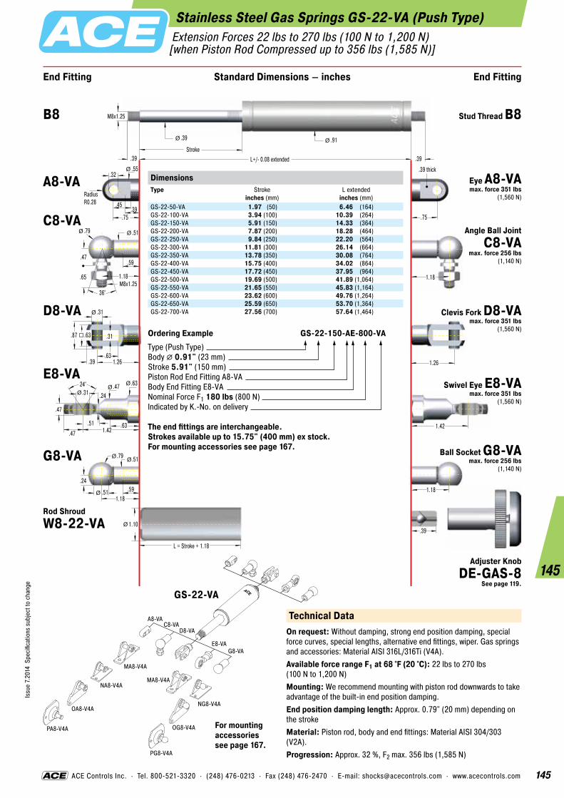
145
Issu
e 7.
2014
Spe
cific
atio
ns s
ubje
ct to
cha
nge
145
ACE Controls Inc. · Tel. 800-521-3320 · (248) 476-0213 · Fax (248) 476-2470 · E-mail: [email protected] · www.acecontrols.com
Stainless Steel Gas Springs GS-22-VA (Push Type) Extension Forces 22 lbs to 270 lbs (100 N to 1,200 N) [when Piston Rod Compressed up to 356 lbs (1,585 N)]
End Fitting End FittingStandard Dimensions – inches
.39
1.181.18
.24
.79 .51
.59.51
M8x1.25
1.18
.39 L+/- 0.08 extended
.39
Stroke.39
.91
L = Stroke + 1.18
1.10
ØØ
Ø
Ø Ø
1.42
Ø
1.18M8x1.25
.47
.79 .51
.59
.65
36°
Ø Ø
1.26
.75
24° .47 .31
.47
.63
.63
.24
.47 1.42.51
ØØ
Ø
.31
.63
.31
.39 1.26
.63
Ø
.87
.45
.75
.32
.39
.55Ø
RadiusR0.28
.39 thickDimensionsType
Stroke inches (mm)
L extended inches (mm)
GS-22-50-VA 1.97 (50) 6.46 (164)GS-22-100-VA 3.94 (100) 10.39 (264)GS-22-150-VA 5.91 (150) 14.33 (364)GS-22-200-VA 7.87 (200) 18.28 (464)GS-22-250-VA 9.84 (250) 22.20 (564)GS-22-300-VA 11.81 (300) 26.14 (664)GS-22-350-VA 13.78 (350) 30.08 (764)GS-22-400-VA 15.75 (400) 34.02 (864)GS-22-450-VA 17.72 (450) 37.95 (964)GS-22-500-VA 19.69 (500) 41.89 (1,064)GS-22-550-VA 21.65 (550) 45.83 (1,164)GS-22-600-VA 23.62 (600) 49.76 (1,264)GS-22-650-VA 25.59 (650) 53.70 (1,364)GS-22-700-VA 27.56 (700) 57.64 (1,464)
Ordering Example GS-22-150-AE-800-VAType (Push Type)Body � 0.91" (23 mm)Stroke 5.91" (150 mm)Piston Rod End Fitting A8-VABody End Fitting E8-VANominal Force F1 180 lbs (800 N)Indicated by K.-No. on delivery
The end fittings are interchangeable. Strokes available up to 15.75" (400 mm) ex stock. For mounting accessories see page 167.
A8-VA
MA8-V4A
MA8-V4A
NG8-V4A
NA8-V4A
OG8-V4A
OA8-V4A
PA8-V4A
PG8-V4A
C8-VAD8-VA
E8-VAG8-VA
Technical DataOn request: Without damping, strong end position damping, special force curves, special lengths, alternative end fittings, wiper. Gas springs and accessories: Material AISI 316L/316Ti (V4A).Available force range F1 at 68 °F (20 °C): 22 lbs to 270 lbs (100 N to 1,200 N)Mounting: We recommend mounting with piston rod downwards to take advantage of the built-in end position damping.End position damping length: Approx. 0.79" (20 mm) depending on the strokeMaterial: Piston rod, body and end fittings: Material AISI 304/303 (V2A).Progression: Approx. 32 %, F2 max. 356 lbs (1,585 N)
B8 Stud Thread B8
A8-VA Eye A8-VA max. force 351 lbs
(1,560 N)
C8-VAAngle Ball Joint
C8-VA max. force 256 lbs
(1,140 N)
D8-VA Clevis Fork D8-VA max. force 351 lbs
(1,560 N)
E8-VASwivel Eye E8-VA
max. force 351 lbs(1,560 N)
G8-VA Ball Socket G8-VA max. force 256 lbs
(1,140 N)
Rod Shroud W8-22-VA
For mounting accessories see page 167.
GS-22-VA
Adjuster Knob DE-GAS-8
See page 119.
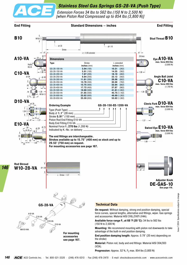
146
Issu
e 7.
2014
Spe
cific
atio
ns s
ubje
ct to
cha
nge
146
ACE Controls Inc. · Tel. 800-521-3320 · (248) 476-0213 · Fax (248) 476-2470 · E-mail: [email protected] · www.acecontrols.com
Stainless Steel Gas Springs GS-28-VA (Push Type) Extension Forces 34 lbs to 562 lbs (150 N to 2,500 N) [when Piston Rod Compressed up to 854 lbs (3,800 N)]
End Fitting End FittingStandard Dimensions – inches
.47
M10x1.5
1.38
.47 L+/- 0.08 extended
.55
Stroke.47
1.10
L = Stroke + 1.57
1.26
Ø Ø
1.69
Ø
1.38M10x1.5
.63
.94 .63
.71
.79
36°
Ø Ø
1.57
1.06
24° .59 .39
.55
.71
.75
.28
.55 1.69.63
ØØ
Ø
.39
.79
.39
.47 1.57
.79
Ø
1.04
.59
1.06
.32
.59
.71Ø
RadiusR0.35
.39 thickDimensionsType
Stroke inches (mm)
L extended inches (mm)
GS-28-100-VA 3.94 (100) 10.31 (262)GS-28-150-VA 5.91 (150) 14.25 (362)GS-28-200-VA 7.87 (200) 18.19 (462)GS-28-250-VA 9.84 (250) 22.13 (562)GS-28-300-VA 11.81 (300) 26.06 (662)GS-28-350-VA 13.78 (350) 30.00 (762)GS-28-400-VA 15.75 (400) 33.94 (862)GS-28-450-VA 17.72 (450) 37.87 (962)GS-28-500-VA 19.69 (500) 41.81 (1,062)GS-28-550-VA 21.65 (550) 45.75 (1,162)GS-28-600-VA 23.62 (600) 49.69 (1,262)GS-28-650-VA 25.59 (650) 53.62 (1,362)
Ordering Example GS-28-150-EE-1200-VAType (Push Type)Body � 1.1" (28 mm)Stroke 5.91" (150 mm)Piston Rod End Fitting E10-VABody End Fitting E10-VANominal Force F1 270 lbs (1,200 N)Indicated by K.-No. on delivery
The end fittings are interchangeable. Strokes available up to 15.75" (400 mm) ex stock and up to 29.53" (750 mm) on request. For mounting accessories see page 167.
A10-VAC10-VA
D10-VAE10-VA
MA10-V4A
Technical DataOn request: Without damping, strong end position damping, special force curves, special lengths, alternative end fittings, wiper. Gas springs and accessories: Material AISI 316L/316Ti (V4A).Available force range F1 at 68 °F (20 °C): 34 lbs to 562 lbs (150 N to 2,500 N)Mounting: We recommend mounting with piston rod downwards to take advantage of the built-in end position damping.End position damping length: Approx. 0.79" (20 mm) depending on the stroke)Material: Piston rod, body and end fittings: Material AISI 304/303 (V2A).Progression: Approx. 52 %, F2 max. 854 lbs (3,800 N)
B10 Stud Thread B10
A10-VA Eye A10-VA max. force 854 lbs
(3,800 N)
C10-VAAngle Ball Joint
C10-VA max. force 393 lbs
(1,750 N)
D10-VA Clevis Fork D10-VA max. force 854 lbs
(3,800 N)
E10-VASwivel Eye E10-VA
max. force 854 lbs(3,800 N)
Rod Shroud W10-28-VA
For mounting accessories see page 167.
GS-28-VA
Adjuster Knob DE-GAS-10
See page 119.

147
Issu
e 7.
2014
Spe
cific
atio
ns s
ubje
ct to
cha
nge
147
ACE Controls Inc. · Tel. 800-521-3320 · (248) 476-0213 · Fax (248) 476-2470 · E-mail: [email protected] · www.acecontrols.com
A14-VAC14-VA
D14-VAE14-VA
ME14-VA
ME14-VA
ND14-VA
Stainless Steel Gas Springs GS-40-VA (Push Type) Extension Forces 112 lbs to 1,124 lbs (500 N to 5,000 N) [when Piston Rod Compressed up to 1,574 lbs (7,000 N)]
End Fitting End FittingStandard Dimensions – inches
.59
M14x1.5
1.77
.59 L +/- 0.08 extended
.79Stroke
.59
1.57
L = Stroke + 1.57
1.77
Ø Ø
2.24
Ø
1.77M14x1.5
.79
1.18 .87
.98
1.1
36°
Ø Ø
2.20
1.65
30° .79 .55
.75
1.18
1.02
.51
.71 2.24.71
ØØ
Ø
.55
1.06
.55
.63 2.20
1.06
Ø
1.38
.77
1.65
.56
.71
.98Ø
RadiusR0.49
.55 thickDimensionsType
Stroke inches (mm)
L extended inches (mm)
GS-40-100-VA 3.94 (100) 12.48 (317)GS-40-150-VA 5.91 (150) 16.42 (417)GS-40-200-VA 7.87 (200) 20.35 (517)GS-40-300-VA 11.81 (300) 28.23 (717)GS-40-400-VA 15.75 (400) 36.10 (917)GS-40-500-VA 19.69 (500) 43.98 (1,117)GS-40-600-VA 23.62 (600) 51.85 (1,317)
Ordering Example GS-40-150-DD-3500-VAType (Push Type)Body � 1.57" (40 mm)Stroke 5.91" (150 mm)Piston Rod End Fitting D14-VABody End Fitting D14-VANominal Force F1 787 lbs (3,500 N)Indicated by K.-No. on delivery
The end fittings are interchangeable. Strokes also available up to 39.37" (1,000 mm). For mounting accessories see page 168.
GS-40-VA Technical DataOn request: Without damping, strong end position damping, special force curves, special lengths, alternative end fittings, wiper. Gas springs and accessories: Material AISI 316L/316Ti (V4A).Available force range F1 at 68 °F (20 °C): 112 lbs to 1,124 lbs (500 N to 5,000 N)Mounting: We recommend mounting with piston rod downwards to take advantage of the built-in end position damping.End position damping length: Approx. 2.24" (30 mm) depending on the strokeMaterial: Piston rod, body and end fittings: Material AISI 304/303 (V2A).Progression: Approx. 40 %, F2 max. 1,574 lbs (7,000 N)
B14 Stud Thread B14
A14-VA Eye A14-VA max. force 1,574 lbs
(7,000 N)
C14-VA Angle Ball Joint C14-VA
max. force 719 lbs(3,200 N)
D14-VA Clevis Fork D14-VA max. force 1,574 lbs
(7,000 N)
E14-VASwivel Eye E14-VA
max. force 1,574 lbs(7,000 N)
Rod Shroud W14-40-VA
For mounting accessories see page 168.
Adjuster Knob DE-GAS-14
See page 119.

148
Issu
e 7.
2014
Spe
cific
atio
ns s
ubje
ct to
cha
nge
148
ACE Controls Inc. · Tel. 800-521-3320 · (248) 476-0213 · Fax (248) 476-2470 · E-mail: [email protected] · www.acecontrols.com
Industrial Gas SpringsApplication Examples
Doors open and close safely
Protection under the hood
ACE industrial gas springs make opening and closing doors of rescue helicopters easier. The maintenance-free, sealed systems are installed in the access doors of helicopters of the type EC 135. There, they allow the crew to enter or exit the helicopter quickly, thus contributing to en- hanced safety. The GS-19-300-CC gas springs provide a defined retraction speed and secure engagement of the door lock. The integrated end position damper allows gentle closing of the door and saves wear and tear on the valuable, lightweight material.
ACE industrial gas springs prevent injuries during maintenance work on harvesting machines. The blades of corn pickers are arranged under plastic hoods, which assure proper material flow within the machine. For maintenance purposes, the hoods, weighing about 15 lbs, must be lifted up. To protect maintenance personnel from injury by falling hoods, they are kept in the open position by industrial gas springs of the type GS-22-250-DD. Another advantage they offer is their stability under rough operating conditions due to their wear-resistant coating on the piston rod and the coated housing.
Industrial gas springs: For safe entry and exit
Enhanced protection: Industrial gas springs secure heavy hoods

149
Issu
e 7.
2014
Spe
cific
atio
ns s
ubje
ct to
cha
nge
149
Traction Gas Springs GZ-15 to GZ-40 (Pull Type)
Industrial traction gas springs are main- tenance-free and ready to install. They are available ex-stock with body diameters from 0.59" to 1.57" and forces from 7 lbs to 1,124 lbs (30 N to 5,000 N) with valve. ACE traction gas springs offer a long service life due to the hard-chromed piston rod and integral sliding bearing. They can be installed in any position. The traction force can be subse-quently adjusted by means of the valve. The comprehensive range of fitting parts ensures easy installation and makes the traction gas springs universal in use. They supply the muscle force and enable the controlled raising and lowering of covers, hoods, flaps etc. With the free ACE calculation service, the traction gas springs are designed with mounting points to fit the individual application, and can be delivered ex-stock as express deliveries within 24 hours.
Function: ACE industrial traction gas springs are maintenance-free, closed systems, which are filled with pressurised nitrogen gas. Compared to the push type, ACE traction gas springs work in the reverse way. The piston rod is retracted by the gas pressure in the cylinder. The surface of the piston ring be- tween the piston rod and the inner tube determines the force of the gas spring. Traction gas springs are always mounted with the stroke fully compressed.Operating fluid: Nitrogen gasMounting: In any positionOperating temperature range: -4 °F to 176 °FOn request: Special force curves, special lengths, alternative seals and end fittings.
Filled with High Pressure Nitrogen Gas
Seals
Piston Rod
Gas Valve
Main Bearing
Outer Body
Piston with Seals

150
Issu
e 7.
2014
Spe
cific
atio
ns s
ubje
ct to
cha
nge
150
ACE Controls Inc. · Tel. 800-521-3320 · (248) 476-0213 · Fax (248) 476-2470 · E-mail: [email protected] · www.acecontrols.com
A3.5C3.5
D3.5E3.5
G3.5NA3.5
OA3.5A3.5
OG3.5
NG3.5
Industrial Traction Gas Springs GZ-15 (Pull Type) Traction (Pull) Forces 11 lbs to 34 lbs (50 N to 150 N) [when Piston Rod Extended up to 42 lbs (185 N)]
End Fitting End FittingStandard Dimensions – inches
.20
24° .31 .16
.20
.21
.28 .47.29
ØØ
.28
.71.71
.16
.51 .31
.24.31
.20
M3.5x0.6
.71
.31
.31
.47 L+/- 0.08 retracted
.16
.16
Stroke
RadiusR0.16
.16 thick
.47
.16 thick
.61 .31
ØØ
Ø
Ø Ø
ØØ
.16
.31
.16
.20 .63
.31
Ø
Ø
.71M4x0.7
.33
.51 .31
.24
.39
36°
Ø Ø
.20
.16
.63
.47
DimensionsType
Stroke inches (mm)
L retracted inches (mm)
GZ-15-20 0.79 (20) 3.43 (87)GZ-15-40 1.57 (40) 4.21 (107)GZ-15-50 1.97 (50) 4.61 (117)GZ-15-60 2.36 (60) 5.00 (127)GZ-15-80 3.15 (80) 5.79 (147)GZ-15-100 3.94 (100) 6.57 (167)GZ-15-120 4.72 (120) 7.36 (187)GZ-15-150 5.91 (150) 8.54 (217)
Ordering Example GZ-15-150-AC-V-150Type (Pull Type)Body � 0.59" (15 mm)Stroke 5.91" (150 mm)Piston Rod End Fitting A3.5Body End Fitting C3.5Adjustable (V)Traction Force F1 34 lbs (150 N)
The end fittings are interchangeable and must be positively secured by the customer to prevent unscrewing (i.e. Loctite). For mounting accessories see page 163.
GZ-15
Technical DataOn request: Special force curves, special lengths, alternative end fittings, rod shroud.Mounting: In any position. Install mechanical stop in extended position.End position damping length: Without dampingMaterial: Piston rod: Hard chrome plated. Body: Black coated. End fittings: Zinc plated steel.Progression: Approx. 23 %, F2 max. 42 lbs (185 N)Available traction force range F1 at 68 °F (20 °C): 11 lbs to 34 lbs (50 N to 150 N)Note: Lifetime approx. 6,561 ft (2,000 m)
A3.5 Eye A3.5 max. force 83 lbs
(370 N)
B3.5 Stud Thread B3.5
C3.5 Angle Ball Joint C3.5
max. force 83 lbs(370 N)
D3.5 Clevis Fork D3.5 max. force 83 lbs
(370 N)
E3.5 Swivel Eye E3.5 max. force 83 lbs
(370 N)
G3.5 Ball Socket G3.5 max. force 83 lbs
(370 N)
For mounting accessories see page 163.
Adjuster Knob DE-GAS-3.5
See page 119.

151
Issu
e 7.
2014
Spe
cific
atio
ns s
ubje
ct to
cha
nge
151
ACE Controls Inc. · Tel. 800-521-3320 · (248) 476-0213 · Fax (248) 476-2470 · E-mail: [email protected] · www.acecontrols.com
Industrial Traction Gas Springs GZ-19 (Pull Type) Traction (Pull) Forces 7 lbs to 67 lbs (30 N to 300 N) [when Piston Rod Extended up to 74 lbs (330 N)]
End Fitting End FittingStandard Dimensions – inches
1.18
1.42
1.26
1.18
.24
.79.51
.59.51
24° .47 .31
.31
.31
.63
.31
.39 1.26
.63
.39
M8x1.25
1.18
.55
.55
.79 L+/- 0.08 retracted
.24
.32
Stroke
RadiusR0.28
.39 thick
.79
.39 thick
.75 .55
L = Stroke + 1.18
.91
1.18M8x1.25
.47
.79 .51
.59
.65
36°
.63
.63
.24
.47 1.42.51
Ø
Ø Ø
ØØ
Ø
Ø Ø
Ø
ØØ
Ø
Ø
Ø
.39
.32
Ø
.39
DimensionsType
Stroke inches (mm)
L retracted inches (mm)
GZ-19-30 1.18 (30) 4.41 (112)GZ-19-50 1.97 (50) 5.20 (132)GZ-19-100 3.94 (100) 7.17 (182)GZ-19-150 5.91 (150) 9.13 (232)GZ-19-200 7.87 (200) 11.10 (282)GZ-19-250 9.84 (250) 13.07 (332)
Ordering Example GZ-19-150-AC-V-250Type (Pull Type)Body � 0.75" (19 mm)Stroke 5.91" (150 mm)Piston Rod End Fitting A8Body End Fitting C8Adjustable (V)Traction Force F1 56 lbs (250 N)
The end fittings are interchangeable and must be positively secured by the customer to prevent unscrewing (i.e. Loctite). For mounting accessories see page 164.
GZ-19
Technical DataOn request: Special force curves, special lengths, alternative end fittings, wiper, stainless steel.Mounting: In any position. Install mechanical stop in extended position.End position damping length: Without damping.Material: Piston rod: Hard chrome plated. Body: Black coated. End fittings: Zinc plated steel.Progression: Approx. 10 %, F2 max. 74 lbs (330 N)Available traction force range F1 at 68 °F (20 °C): 7 lbs to 67 lbs (30 N to 300 N)Note: Lifetime approx. 6,561 ft (2,000 m)
A8 Eye A8 max. force 670 lbs
(3,000 N)
B8 Stud Thread B8
C8 Angle Ball Joint C8
max. force 270 lbs(1,200 N)
D8 Clevis Fork D8 max. force 670 lbs
(3,000 N)
E8 Swivel Eye E8 max. force 670 lbs
(3,000 N)
G8Ball Socket G8
max. force 270 lbs(1,200 N)
Rod Shroud W8-19
For mounting accessories see page 164.
Adjuster Knob DE-GAS-8 See page 119.

152
Issu
e 7.
2014
Spe
cific
atio
ns s
ubje
ct to
cha
nge
152
ACE Controls Inc. · Tel. 800-521-3320 · (248) 476-0213 · Fax (248) 476-2470 · E-mail: [email protected] · www.acecontrols.com
Industrial Traction Gas Springs GZ-28 (Pull Type) Traction (Pull) Forces 34 lbs to 270 lbs (150 N to 1,200 N) [when Piston Rod Extended up to 324 lbs (1,440 N)]
End Fitting End FittingStandard Dimensions – inches
.47
M10x1.5
1.38
.71
.67
.98 L+/- 0.08 retracted
.39
.32
Stroke
RadiusR0.35
.47 thick
.98
.47 thick
1.10 .67
L = Stroke + 1.57
1.26
Ø Ø
Ø
1.69
Ø
.39
.79
.39
.47 1.57
.79
Ø
Ø
Ø
1.38M10x1.5
.63
.94 .63
.71
.79
36°
Ø Ø
.47
.32
1.57
24° .59 .39
.35
.71
.75
.28
.55 1.69.63
ØØØ
.47
DimensionsType
Stroke inches (mm)
L retracted inches (mm)
GZ-28-30 1.18 (30) 5.12 (130)GZ-28-50 1.97 (50) 5.91 (150)GZ-28-100 3.94 (100) 7.87 (200)GZ-28-150 5.91 (150) 9.84 (250)GZ-28-200 7.87 (200) 11.81 (300)GZ-28-250 9.84 (250) 13.78 (350)GZ-28-300 11.81 (300) 15.75 (400)GZ-28-350 13.78 (350) 17.72 (450)GZ-28-400 15.75 (400) 19.69 (500)GZ-28-450 17.72 (450) 21.65 (550)GZ-28-500 19.69 (500) 23.62 (600)GZ-28-550 21.65 (550) 25.59 (650)GZ-28-600 23.62 (600) 27.56 (700)GZ-28-650 25.59 (650) 29.53 (750)
Ordering Example GZ-28-150-EE-V-800Type (Pull Type)Body � 1.10" (28 mm)Stroke 5.91" (150 mm)Piston Rod End Fitting E10Body End Fitting E10Adjustable (V)Traction Force F1 180 lbs (800 N)
The end fittings are interchangeable and must be positively secured by the customer to prevent unscrewing (i.e. Loctite). For mounting accessories see page 164.
GZ-28
Technical DataOn request: Special force curves, special lengths, alternative end fittings, wiper, stainless steel.Mounting: In any position. Install mechanical stop in extended position.End position damping length: Without damping.Material: Piston rod: Hard chrome plated. Body: Black coated. End fittings: Zinc plated steel.Progression: Approx. 20 %, F2 max. 324 lbs (1,440 N)Available traction force range F1 at 68 °F (20 °C): 34 lbs to 270 lbs (150 N to 1200 N)Note: Lifetime approx. 6,561 ft (2,000 m)
A10 Eye A10 max. force 2,248 lbs
(10,000 N)
B10 Stud Thread B10
C10 Angle Ball Joint C10
max. force 405 lbs(1,800 N)
D10 Clevis Fork D10 max. force 2,248 lbs
(10,000 N)
E10 Swivel Eye E10 max. force 2,248 lbs
(10,000 N)
Rod Shroud W10-28
For mounting accessories see page 164.
Adjuster KnobDE-GAS-10 See page 119.
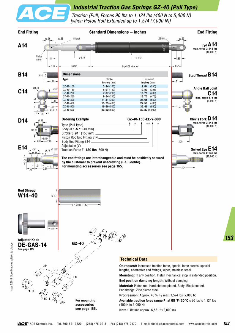
153
Issu
e 7.
2014
Spe
cific
atio
ns s
ubje
ct to
cha
nge
153
ACE Controls Inc. · Tel. 800-521-3320 · (248) 476-0213 · Fax (248) 476-2470 · E-mail: [email protected] · www.acecontrols.com
Industrial Traction Gas Springs GZ-40 (Pull Type) Traction (Pull) Forces 90 lbs to 1,124 lbs (400 N to 5,000 N) [when Piston Rod Extended up to 1,574 (7,000 N)]
.59
End Fitting End FittingStandard Dimensions – inches
2.20
.55
1.06
.55
.63 2.20
1.06
.71
M14x1.5
1.77
.98
.83
1.57 L+/- 0.08 retracted
1.10
.56
Stroke
RadiusR0.49
.55 thick
1.57
.55 thick
1.57 .83
L = Stroke + 1.57
1.77
1.77M14x1.5
.79
1.18 .87
.98
1.1
36°
Ø
Ø Ø
Ø Ø
Ø
2.24
Ø
Ø
Ø
.71
.56
30° .79 .55
.75
1.18
1.02
.51
.71 2.24.71
ØØØ
DimensionsType
Stroke inches (mm)
L retracted inches (mm)
GZ-40-100 3.94 (100) 9.84 (250)GZ-40-150 5.91 (150) 12.80 (325)GZ-40-200 7.87 (200) 15.75 (400)GZ-40-250 9.84 (250) 18.70 (475)GZ-40-300 11.81 (300) 21.65 (550)GZ-40-400 15.75 (400) 27.56 (700)GZ-40-500 19.69 (500) 33.46 (850)GZ-40-600 23.62 (600) 39.37 (1,000)
Ordering Example GZ-40-150-EE-V-800Type (Pull Type)Body � 1.57" (40 mm)Stroke 5.91" (150 mm)Piston Rod End Fitting E14Body End Fitting E14Adjustable (V)Traction Force F1 180 lbs (800 N)
The end fittings are interchangeable and must be positively secured by the customer to prevent unscrewing (i.e. Loctite). For mounting accessories see page 165.
GZ-40
Technical DataOn request: Increased traction force, special force curves, special lengths, alternative end fittings, wiper, stainless steel.Mounting: In any position. Install mechanical stop in extended position.End position damping length: Without dampingMaterial: Piston rod: Hard chrome plated. Body: Black coated. End fittings: Zinc plated steel.Progression: Approx. 40 %, F2 max. 1,574 lbs (7,000 N)Available traction force range F1 at 68 °F (20 °C): 90 lbs to 1,124 lbs (400 N to 5,000 N)Note: Lifetime approx. 6,561 ft (2,000 m)
A14 Eye A14 max. force 2,248 lbs
(10,000 N)
B14 Stud Thread B14
C14 Angle Ball Joint C14
max. force 674 lbs(3,200 N)
D14 Clevis Fork D14 max. force 2,248 lbs
(10,000 N)
E14 Swivel Eye E14 max. force 2,248 lbs
(10,000 N)
Rod Shroud W14-40
For mounting accessories see page 165.
Adjuster Knob DE-GAS-14 See page 119.

154
Issu
e 7.
2014
Spe
cific
atio
ns s
ubje
ct to
cha
nge
154
Stainless Steel Traction Gas Springs (Pull Type)
Stainless steel industrial traction gas springsMaterial AISI 304/303 (V2A)Material AISI 316L/316Ti (V4A)
In addition to the comprehensive range of in- dustrial gas springs with valve, ACE also offers a wide range of industrial traction gas springs made of stainless steel with body diameters from 0.59" to 1.57". This high-quality version is also available on request in all stroke lengths and possible extension forces. The comprehen-sive range of fitting parts ensures easy installation and makes the gas traction springs universal in use. Stainless steel traction gas springs are used everywhere that raising and lowering is required. Due to their special properties, non-rusting and low magnetism, they are the preferred equipment for medical and cleanroom technology, the foodstuffs industry, electronics and shipbuilding sector.
Operating fluid: Nitrogen gasMaterial: Piston rod, body and end fittings: Material AISI 304/303 (V2A) and material AISI 316L/316Ti (V4A).Mounting: In any positionOperating temperature range: -4 °F to 176 °FOn request: Special force curves, special lengths, alternative seals, wiper.
Filled with High Pressure Nitrogen Gas
Seals
Stainless Steel Piston Rod
Gas Valve
Stainless Steel Outer Body
Main Bearing
Piston with Seals
“The weatherproof ones!“

155
Issu
e 7.
2014
Spe
cific
atio
ns s
ubje
ct to
cha
nge
155
ACE Controls Inc. · Tel. 800-521-3320 · (248) 476-0213 · Fax (248) 476-2470 · E-mail: [email protected] · www.acecontrols.com
Stainless Steel Traction Gas Springs GZ-15-V4A (Pull Type) Traction (Pull) Forces 11 lbs to 34 lbs (50 N to 150 N) [when Piston Rod Extended up to 42 lbs (185 N)]
.63
.16
.30
.16
.20 .63
.31
Ø
End Fitting End FittingStandard Dimensions – inches
.28
.71.71
.16
.51.31
.24.31
M3.5x0.6
.71
.20 L +/- 0.08 retracted
.16
Stroke .20
.61
ØØ
Ø
Ø Ø
.71M4x0.7
.33
.51 .31
.24
.39
36°
Ø Ø
.43
.31
.43
.16
.24
.31Ø
RadiusR0.16
.16 thickDimensionsType
Stroke inches (mm)
L retracted inches (mm)
GZ-15-20-V4A 0.79 (20) 3.43 (87)GZ-15-40-V4A 1.57 (40) 4.21 (107)GZ-15-50-V4A 1.97 (50) 4.61 (117)GZ-15-60-V4A 2.36 (60) 5.00 (127)GZ-15-80-V4A 3.15 (80) 5.79 (147)GZ-15-100-V4A 3.94 (100) 6.57 (167)GZ-15-120-V4A 4.72 (120) 7.36 (187)GZ-15-150-V4A 5.91 (150) 8.54 (217)
Ordering Example GZ-15-150-AC-V-150-V4AType (Pull Type)Body � 0.59" (15 mm)Stroke 5.91" (150 mm)Piston Rod End Fitting A3.5-V4A Body End Fitting C3.5-V4AAdjustable (V)Traction Force F1 34 lbs (150 N)Indicated by K.-No. on delivery
The end fittings are interchangeable and must be positively secured by the customer to prevent unscrewing (i.e. Loctite). For mounting accessories see page 166.
A3.5-V4A
C3.5-V4A
NA3.5-V4A
A3.5-V4A
NG3.5-V4A
OG3.5-V4A
OA3.5-V4A
D3.5-V4A
G3.5-V4A
Technical DataOn request: Special force curves, special lengths, alternative end fittings, rod shroud.Mounting: In any position. Install mechanical stop in extended position.End position damping length: Without dampingMaterial: Piston rod, body and end fittings: Material AISI 316L/316Ti (V4A).Progression: Approx. 23%, F2 max. 42 lbs (185 N)Available traction force range F1 at 68 °F (20 °C): 11 lbs to 34 lbs (50 N to 150 N)Note: Lifetime approx. 6,561 ft (2,000 m)
B3.5 Stud Thread B3.5
A3.5-V4A Eye A3.5-V4A
max. force 83 lbs(370 N)
C3.5-V4A Angle Ball Joint C3.5-V4A
max. force 83 lbs(370 N)
D3.5-V4A Clevis Fork D3.5-V4A
max. force 83 lbs(370 N)
G3.5-V4A Ball Socket G3.5-V4A
max. force 83 lbs(370 N)
GZ-15-V4A
For mounting accessories see page 166.
Adjuster Knob DE-GAS-3.5
See page 119.

156
Issu
e 7.
2014
Spe
cific
atio
ns s
ubje
ct to
cha
nge
156
ACE Controls Inc. · Tel. 800-521-3320 · (248) 476-0213 · Fax (248) 476-2470 · E-mail: [email protected] · www.acecontrols.com
A8-V4A
MA8-V4A
MA8-V4A
NG8-V4A
NA8-V4A
OG8-V4A
OA8-V4A
PA8-V4A
PG8-V4A
C8-V4AD8-V4A
E8-V4AG8-V4A
Stainless Steel Traction Gas Springs GZ-19-V4A (Pull Type) Traction (Pull) Forces 7 lbs to 67 lbs (30 N to 300 N) [when Piston Rod Extended up to 75 lbs (333 N)]
.39
End Fitting End FittingStandard Dimensions – inches
1.181.18
.24
.79.51
.59.51
M8x1.25
1.18
.39 L +/- 0.08 retracted
.24
Stroke .39
.75
L = Stroke + 1.18
.91
ØØ
Ø
Ø Ø
1.42
Ø
1.18M8x1.25
.47
.79 .51
.59
.65
36°
Ø Ø
1.26
.75
24° .47 .31
.47
.63
.63
.24
.47 1.42.51
ØØ
Ø
.31
.63
.31
.39 1.26
.63
Ø
.87
.45
.75
.32
.39
.55Ø
RadiusR0.28
.39 thickDimensionsType
Stroke inches (mm)
L retracted inches (mm)
GZ-19-30-V4A 1.18 (30) 5.12 (130)GZ-19-50-V4A 1.97 (50) 5.91 (150)GZ-19-100-V4A 3.94 (100) 7.87 (200)GZ-19-150-V4A 5.91 (150) 9.84 (250)GZ-19-200-V4A 7.87 (200) 11.81 (300)GZ-19-250-V4A 9.84 (250) 13.78 (350)
Ordering Example GZ-19-150-AC-V-150-V4AType (Pull Type)Body � 0.75" (19 mm)Stroke 5.91" (150 mm)Piston Rod End Fitting A8-V4A Body End Fitting C8-V4AAdjustable (V)Traction Force F1 34 lbs (150 N)Indicated by K.-No. on delivery
The end fittings are interchangeable and must be positively secured by the customer to prevent unscrewing (i.e. Loctite). For mounting accessories see page 167.
GZ-19-V4A
B8 Stud Thread B8
A8-V4A Eye A8-V4A max. force 351 lbs
(1,560 N)
C8-V4A Angle Ball Joint C8-V4A
max. force 256 lbs(1,140 N)
D8-V4A Clevis Fork D8-V4A max. force 351 lbs
(1,560 N)
E8-V4ASwivel Eye E8-V4A
max. force 351 lbs(1,560 N)
G8-V4A Ball Socket G8-V4A max. force 256 lbs
(1,140 N)
Rod Shroud W8-19-V4A
For mounting accessories see page 167.
Adjuster Knob DE-GAS-8 See page 119. Technical Data
On request: Special force curves, special lengths, alternative end fittings, wiper.Mounting: In any position. Install mechanical stop in extended position.End position damping length: Without dampingMaterial: Piston rod, body and end fittings: Material AISI 316L/316Ti (V4A).Progression: Approx. 11%, F2 max. 75 lbs (333 N)Available traction force range F1 at 68 °F (20 °C): 7 lbs to 67 lbs (30 N to 300 N)Note: Lifetime approx. 6,561 ft (2,000 m)

157
Issu
e 7.
2014
Spe
cific
atio
ns s
ubje
ct to
cha
nge
157
ACE Controls Inc. · Tel. 800-521-3320 · (248) 476-0213 · Fax (248) 476-2470 · E-mail: [email protected] · www.acecontrols.com
A10-V4AC10-V4A
D10-V4AE10-V4A
MA10-V4A
Stainless Steel Traction Gas Springs GZ-28-V4A (Pull Type) Traction (Pull) Forces 34 lbs to 270 lbs (150 N to 1,200 N) [when Piston Rod Extended up to 328 lbs (1,460 N)]
.47
End Fitting End FittingStandard Dimensions – inches
M10x1.5
1.38
.47 .47
L = Stroke + 1.57
1.26
1.69
Ø
1.38M10x1.5
.63
.94 .63
.71
.79
36°
Ø Ø
1.57
1.06
24° .59 .39
.55
.71
.75
.28
.55 1.69.63
ØØ
Ø
.39
.79
.39
.47 1.57
.79
Ø
1.04
.59
1.06
.32
.59
.71Ø
RadiusR0.35
.39 thickL +/- 0.08 retracted
.39
Stroke
1.10Ø Ø
GZ-28-V4A
Technical DataOn request: Special force curves, special lengths, alternative end fittings, wiper. Mounting: In any position. Install mechanical stop in extended position.End position damping length: Without dampingMaterial: Piston rod, body and end fittings: Material AISI 316L/316Ti (V4A).Progression: Approx. 11%, F2 max. 328 lbs (1,460 N)Available traction force range F1 at 68 °F (20 °C): 34 lbs to 270 lbs (150 N to 1,200 N)Note: Lifetime approx. 6,561 ft (2,000 m)
DimensionsType
Stroke inches (mm)
L retracted inches (mm)
GZ-28-50-V4A 1.97 (50) 6.50 (165)GZ-28-100-V4A 3.94 (100) 8.46 (215)GZ-28-150-V4A 5.91 (150) 10.43 (265)GZ-28-200-V4A 7.87 (200) 12.40 (315)GZ-28-250-V4A 9.84 (250) 14.37 (365)GZ-28-300-V4A 11.81 (300) 16.34 (415)GZ-28-350-V4A 13.78 (350) 18.31 (465)GZ-28-400-V4A 15.75 (400) 20.28 (515)GZ-28-450-V4A 17.72 (450) 22.24 (565)GZ-28-500-V4A 19.69 (500) 24.21 (615)GZ-28-550-V4A 21.65 (550) 26.18 (665)GZ-28-600-V4A 23.62 (600) 28.15 (715)
Ordering Example GZ-28-150-EE-V-800-V4AType (Pull Type)Body � 1.10" (28 mm)Stroke 5.91" (150 mm)Piston Rod End Fitting E10-V4A Body End Fitting E10-V4AAdjustable (V)Traction Force F1 180 lbs (800 N)Indicated by K.-No. on delivery
The end fittings are interchangeable and must be positively secured by the customer to prevent unscrewing (i.e. Loctite). For mounting accessories see page 167.
B10 Stud Thread B10
A10-V4A Eye A10-V4A max. force 854 lbs
(3,800 N)
C10-V4A Angle Ball Joint C10-V4A max. force 393 lbs
(1,750 N)
D10-V4A Clevis Fork D10-V4A max. force 854 lbs
(3,800 N)
E10-V4ASwivel Eye E10-V4A
max. force 854 lbs(3,800 N)
Rod Shroud W10-28-V4A
Adjuster Knob DE-GAS-10 See page 119.
For mounting accessories see page 167.
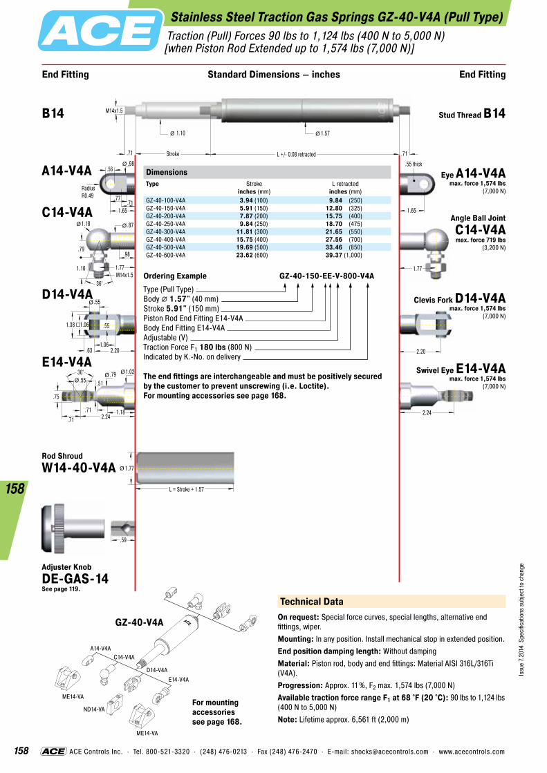
158
Issu
e 7.
2014
Spe
cific
atio
ns s
ubje
ct to
cha
nge
158
ACE Controls Inc. · Tel. 800-521-3320 · (248) 476-0213 · Fax (248) 476-2470 · E-mail: [email protected] · www.acecontrols.com
A14-V4AC14-V4A
D14-V4AE14-V4A
ME14-VA
ME14-VA
ND14-VA
Stainless Steel Traction Gas Springs GZ-40-V4A (Pull Type) Traction (Pull) Forces 90 lbs to 1,124 lbs (400 N to 5,000 N) [when Piston Rod Extended up to 1,574 lbs (7,000 N)]
.59
End Fitting End FittingStandard Dimensions – inches
M14x1.5
1.77
.71 L +/- 0.08 retracted
1.10
Stroke .71
1.57
L = Stroke + 1.57
1.77
Ø Ø
2.24
Ø
1.77M14x1.5
.79
1.18 .87
.98
1.10
36°
Ø Ø
2.20
1.65
30° .79 .55
.75
1.18
1.02
.51
.71 2.24.71
ØØØ
.55
1.06
.55
.63 2.20
1.06
Ø
1.38
.77
1.65
.56
.71
.98Ø
RadiusR0.49
.55 thick
GZ-40-V4A
For mounting accessories see page 168.
Technical DataOn request: Special force curves, special lengths, alternative end fittings, wiper. Mounting: In any position. Install mechanical stop in extended position.End position damping length: Without dampingMaterial: Piston rod, body and end fittings: Material AISI 316L/316Ti (V4A).Progression: Approx. 11%, F2 max. 1,574 lbs (7,000 N)Available traction force range F1 at 68 °F (20 °C): 90 lbs to 1,124 lbs (400 N to 5,000 N)Note: Lifetime approx. 6,561 ft (2,000 m)
DimensionsType
Stroke inches (mm)
L retracted inches (mm)
GZ-40-100-V4A 3.94 (100) 9.84 (250)GZ-40-150-V4A 5.91 (150) 12.80 (325)GZ-40-200-V4A 7.87 (200) 15.75 (400)GZ-40-250-V4A 9.84 (250) 18.70 (475)GZ-40-300-V4A 11.81 (300) 21.65 (550)GZ-40-400-V4A 15.75 (400) 27.56 (700)GZ-40-500-V4A 19.69 (500) 33.46 (850)GZ-40-600-V4A 23.62 (600) 39.37 (1,000)
Ordering Example GZ-40-150-EE-V-800-V4AType (Pull Type)Body � 1.57" (40 mm)Stroke 5.91" (150 mm)Piston Rod End Fitting E14-V4A Body End Fitting E14-V4AAdjustable (V)Traction Force F1 180 lbs (800 N)Indicated by K.-No. on delivery
The end fittings are interchangeable and must be positively secured by the customer to prevent unscrewing (i.e. Loctite). For mounting accessories see page 168.
B14 Stud Thread B14
A14-V4A Eye A14-V4A max. force 1,574 lbs
(7,000 N)
C14-V4A Angle Ball Joint C14-V4A max. force 719 lbs
(3,200 N)
D14-V4A Clevis Fork D14-V4A max. force 1,574 lbs
(7,000 N)
E14-V4ASwivel Eye E14-V4A
max. force 1,574 lbs(7,000 N)
Rod Shroud W14-40-V4A
Adjuster Knob DE-GAS-14 See page 119.

159
Issu
e 7.
2014
Spe
cific
atio
ns s
ubje
ct to
cha
nge
159
ACE Controls Inc. · Tel. 800-521-3320 · (248) 476-0213 · Fax (248) 476-2470 · E-mail: [email protected] · www.acecontrols.com
A8-VA
MA8-V4A
MA8-V4A
NG8-V4A
NA8-V4A
OG8-V4A
OA8-V4A
PA8-V4A
PG8-V4A
C8-VAD8-VA
E8-VAG8-VA
Stainless Steel Traction Gas Springs GZ-19-VA (Pull Type) Traction (Pull) Forces 7 lbs to 67 lbs (30 N to 300 N) [when Piston Rod Extended up to 75 lbs (333 N)]
.39
End Fitting End FittingStandard Dimensions – inches
1.181.18
.24
.79 .51
.59.51
M8x1.25
1.18
.39 L +/- 0.08 retracted
.24
Stroke .39
.75
L = Stroke + 1.18
.91
ØØ
Ø
Ø Ø
1.42
Ø
1.18M8x1.25
.47
.79 .51
.59
.65
36°
Ø Ø
1.26
.75
24° .47 .31
.47
.63
.63
.24
.47 1.42.51
ØØØ
.31
.63
.31
.39 1.26
.63
Ø
.87
.45
.75
.32
.39
.55Ø
RadiusR0.28
.39 thickDimensionsType
Stroke inches (mm)
L retracted inches (mm)
GZ-19-30-VA 1.18 (30) 5.12 (130)GZ-19-50-VA 1.97 (50) 5.91 (150)GZ-19-100-VA 3.94 (100) 7.87 (200)GZ-19-150-VA 5.91 (150) 9.84 (250)GZ-19-200-VA 7.87 (200) 11.81 (300)GZ-19-250-VA 9.84 (250) 13.78 (350)
Ordering Example GZ-19-150-AC-V-150-VAType (Pull Type)Body � 0.75" (19 mm)Stroke 5.91" (150 mm)Piston Rod End Fitting A8-VA Body End Fitting C8-VAAdjustable (V)Traction Force F1 34 lbs (150 N)Indicated by K.-No. on delivery
The end fittings are interchangeable and must be positively secured by the customer to prevent unscrewing (i.e. Loctite). For mounting accessories see page 167.
GZ-19-VA
B8 Stud Thread B8
A8-VA Eye A8-VA max. force 351 lbs
(1,560 N)
C8-VAAngle Ball Joint
C8-VA max. force 256 lbs
(1,140 N)
D8-VA Clevis Fork D8-VA max. force 351 lbs
(1,560 N)
E8-VASwivel Eye E8-VA
max. force 351 lbs(1,560 N)
G8-VABall Socket G8-VA
max. force 256 lbs(1,140 N)
Rod Shroud W8-19-VA
For mounting accessories see page 167.
Adjuster Knob DE-GAS-8 See page 119. Technical Data
On request: Special force curves, special lengths, alternative end fittings, wiper. Gas springs and accessories with material AISI 316L/316Ti (V4A).Mounting: In any position. Install mechanical stop in extended position.End position damping length: Without dampingMaterial: Piston rod: Material AISI 316L (V4A). Body and end fittings: Material AISI 304 (V2A).Progression: Approx. 11%, F2 max. 75 lbs (333 N)Available traction force range F1 at 68 °F (20 °C): 7 lbs to 67 lbs (30 N to 300 N)Note: Lifetime approx. 6,561 ft (2,000 m)
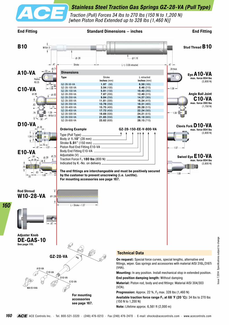
160
Issu
e 7.
2014
Spe
cific
atio
ns s
ubje
ct to
cha
nge
160
ACE Controls Inc. · Tel. 800-521-3320 · (248) 476-0213 · Fax (248) 476-2470 · E-mail: [email protected] · www.acecontrols.com
Stainless Steel Traction Gas Springs GZ-28-VA (Pull Type) Traction (Pull) Forces 34 lbs to 270 lbs (150 N to 1,200 N) [when Piston Rod Extended up to 328 lbs (1,460 N)]
.47
End Fitting End FittingStandard Dimensions – inches
M10x1.5
1.38
.47 .47
L = Stroke + 1.57
1.26
1.69
Ø
1.38M10x1.5
.63
.94 .63
.71
.79
36°
Ø Ø
1.57
1.06
24° .59 .39
.55
.71
.75
.28
.55 1.69.63
ØØØ
.39
.79
.39
.47 1.57
.79
Ø
1.04
.59
1.06
.32
.59
.71Ø
RadiusR0.35
.39 thickL +/- 0.08 retracted
.39
Stroke
1.10Ø Ø
DimensionsType
Stroke inches (mm)
L retracted inches (mm)
GZ-28-50-VA 1.97 (50) 6.50 (165)GZ-28-100-VA 3.94 (100) 8.46 (215)GZ-28-150-VA 5.91 (150) 10.43 (265)GZ-28-200-VA 7.87 (200) 12.40 (315)GZ-28-250-VA 9.84 (250) 14.37 (365)GZ-28-300-VA 11.81 (300) 16.34 (415)GZ-28-350-VA 13.78 (350) 18.31 (465)GZ-28-400-VA 15.75 (400) 20.28 (515)GZ-28-450-VA 17.72 (450) 22.24 (565)GZ-28-500-VA 19.69 (500) 24.21 (615)GZ-28-550-VA 21.65 (550) 26.18 (665)GZ-28-600-VA 23.62 (600) 28.15 (715)
Ordering Example GZ-28-150-EE-V-800-VAType (Pull Type)Body � 1.10" (28 mm)Stroke 5.91" (150 mm)Piston Rod End Fitting E10-VA Body End Fitting E10-VAAdjustable (V)Traction Force F1 180 lbs (800 N)Indicated by K.-No. on delivery
The end fittings are interchangeable and must be positively secured by the customer to prevent unscrewing (i.e. Loctite). For mounting accessories see page 167.
A10-VAC10-VA
D10-VAE10-VA
MA10-V4A
Technical DataOn request: Special force curves, special lengths, alternative end fittings, wiper. Gas springs and accessories with material AISI 316L/316Ti (V4A).Mounting: In any position. Install mechanical stop in extended position.End position damping length: Without dampingMaterial: Piston rod, body and end fittings: Material AISI 304/303 (V2A).Progression: Approx. 22 %, F2 max. 328 lbs (1,460 N)Available traction force range F1 at 68 °F (20 °C): 34 lbs to 270 lbs (150 N to 1,200 N)Note: Lifetime approx. 6,561 ft (2,000 m)
B10 Stud Thread B10
A10-VA Eye A10-VA max. force 854 lbs
(3,800 N)
C10-VAAngle Ball Joint
C10-VA max. force 393 lbs
(1,750 N)
D10-VA Clevis Fork D10-VA max. force 854 lbs
(3,800 N)
E10-VASwivel Eye E10-VA
max. force 854 lbs(3,800 N)
Rod Shroud W10-28-VA
GZ-28-VA
For mounting accessories see page 167.
Adjuster Knob DE-GAS-10 See page 119.

161
Issu
e 7.
2014
Spe
cific
atio
ns s
ubje
ct to
cha
nge
161
ACE Controls Inc. · Tel. 800-521-3320 · (248) 476-0213 · Fax (248) 476-2470 · E-mail: [email protected] · www.acecontrols.com
Stainless Steel Traction Gas Springs GZ-40-VA (Pull Type) Traction (Pull) Forces 90 lbs to 1,124 lbs (400 N to 5,000 N) [when Piston Rod Extended up to 1,574 lbs (7,000 N)]
.59
End Fitting End FittingStandard Dimensions – inches
M14x1.5
1.77
.71 L +/- 0.08 retracted
1.10
Stroke .71
1.57
L = Stroke + 1.57
1.77
Ø Ø
2.24
Ø
1.77M14x1.5
.79
1.18 .87
.98
1.10
36°
Ø Ø
2.20
1.65
30° .79 .55
.75
1.18
1.02
.51
.71 2.24.71
ØØØ
.55
1.06
.55
.63 2.20
1.06
Ø
1.38
.77
1.65
.56
.71
.98Ø
RadiusR0.49
.55 thickDimensionsType
Stroke inches (mm)
L retracted inches (mm)
GZ-40-100-VA 3.94 (100) 9.84 (250)GZ-40-150-VA 5.91 (150) 12.80 (325)GZ-40-200-VA 7.87 (200) 15.75 (400)GZ-40-250-VA 9.84 (250) 18.70 (475)GZ-40-300-VA 11.81 (300) 21.65 (550)GZ-40-400-VA 15.75 (400) 27.56 (700)GZ-40-500-VA 19.69 (500) 33.46 (850)GZ-40-600-VA 23.62 (600) 39.37 (1,000)
Ordering Example GZ-40-150-EE-V-800-VAType (Pull Type)Body � 1.57" (40 mm)Stroke 5.91" (150 mm)Piston Rod End Fitting E14-VA Body End Fitting E14-VAAdjustable (V)Traction Force F1 180 lbs (800 N)Indicated by K.-No. on delivery
The end fittings are interchangeable and must be positively secured by the customer to prevent unscrewing (i.e. Loctite). For mounting accessories see page 168.
A14-VAC14-VA
D14-VAE14-VA
ME14-VA
ME14-VA
ND14-VA
B14 Stud Thread B14
A14-VA Eye A14-VA max. force 1,574 lbs
(7,000 N)
C14-VAAngle Ball Joint
C14-VA max. force 719 lbs
(3,200 N)
D14-VA Clevis Fork D14-VA max. force 1,574 lbs
(7,000 N)
E14-VASwivel Eye E14-VA
max. force 1,574 lbs(7,000 N)
Rod Shroud W14-40-VA
For mounting accessories see page 168.
GZ-40-VATechnical Data
On request: Increased traction force, special force curves, special lengths, alternative end fittings, wiper. Gas springs and accessories with material AISI 316L/316Ti (V4A).Mounting: In any position. Install mechanical stop in extended position.End position damping length: Without dampingMaterial: Piston rod, body and end fittings: Material AISI 304/303 (V2A).Progression: Approx. 40 %, F2 max. 1,574 lbs (7,000 N)Available traction force range F1 at 68 °F (20 °C): 90 lbs to 1,124 lbs (400 N to 5,000 N)Note: Lifetime approx. 6,561 ft (2,000 m)
Adjuster Knob DE-GAS-14 See page 119.

162
Issu
e 7.
2014
Spe
cific
atio
ns s
ubje
ct to
cha
nge
162
Interchangeable Combinable
Gas Spring and Hydraulic Damper AccessoriesEnd Fittings and Mounting Brackets
By taking advantage of the very extensive range of ACE end fittings and mounting brackets you can easily and simply install our gas springs and hydraulic dampers. You profit from the variety of DIN Standard end fittings such as swivel eyes, clevis forks, angle ball joints, inline ball joints, and complementary ball sockets. ACE also offers eye fittings made of wear-resistant steel to meet the higher specification requirements found in industrial applications. With over 30 different types available these mounting accessories provide an extensive range of combinations for opti- mum installations. With the ACE selection programme you can choose not only your ACE gas springs but also the ideal end fittings and mounting brackets for your individual appli- cation example.
The complete range of accessories are also available as individual components.
The wide range of mounting brackets available
“Just drill 4 holes – ACE does all the rest !”

163
Issu
e 7.
2014
Spe
cific
atio
ns s
ubje
ct to
cha
nge
163
ACE Controls Inc. · Tel. 800-521-3320 · (248) 476-0213 · Fax (248) 476-2470 · E-mail: [email protected] · www.acecontrols.com
Steel Mounting AccessoriesEnd Fittings and Mounting Brackets
Accessories M3.5x0.6 GS-8, GS-10, GS-12, GZ-15, HB-12
Accessories M5x0.8 GS-15, HBD-15, HB-15
C3.5 D3,5 E3.5 G3.5
.71M4x0.7
.33
.51 .31
.24
.39
36°
Ø Ø
M3.5.16
.31
.16
.20 .63
.31
Ø
M3.5 M3.5
24° .31
.16
.20
.21
.28 .47.29
ØØ
.28
.71
.16
.51 .31
.24.31
ØØ
Ø
M3.5
1 max. force 83 lbs (370 N) 1 max. force 83 lbs (370 N) 1 max. force 83 lbs (370 N) 1 max. force 83 lbs (370 N)
NA3.5 NG3.5 OA3.5 OG3.51 max. force 40 lbs (180 N)1 max. force 40 lbs (180 N)
.31
.63.12.75.06
.13
.16
.39ØØ
.16
.14 .18
.23 .17
Ø .31
.49
1.18Ø
.71.20
.20
.63.31
.51
.20
.17Ø
Ø
.16.04
.08.06
.18 .18
Ø .31
.22
.53
Ø
A5 C5 D5 E5 F5
.39
.63
.24.24 thick
M5
.31
.39Ø
RadiusR0.20 .87
M5
.31
.51 .31
.47
.39
36°
Ø Ø
M5.20
.39
.20
.24 .79
.39
Ø
M5
24° .39 .24
.24
.47
.51
.18
.39 1.18.47
ØØØ
M5
.391.10
AF .51
.79
45°M5 .31Ø
M5
1 max. force 180 lbs (800 N) 1 max. force 112 lbs (500 N) 1 max. force 180 lbs (800 N) 1 max. force 180 lbs (800 N) 1 max. force 112 lbs (500 N)
G5 1 max. force 112 lbs (500 N) MA5 NA5 NG51 max. force 90 lbs (400 N)
.87
.18
.51 .31
.47.31
ØØ
Ø
M5
1 max. force 112 lbs (500 N)
1.42.372.01
.10.26.51
.79
.35Ø
.24
.26
.71
.10 .16Ø
1.34.201.57.08
.21
.39
.63Ø.24
.24 .28
.39 .39
Ø .31
.51
.20Ø
.71.20
.20
.61.31
.51
.20
.17Ø
Ø
.24.04
.10.06
.26 .26
Ø .31
.22
.53
Ø
1.73
2.171.61.21Ø
.24
.39
.10
.55 .28
Ø .31
.83
.31
.08Ø
1 max. force 40 lbs (180 N) OA5 OG5 1 max. force 112 lbs (500 N) PA5 PG5
Attention! Must only be used with compression loads.
1 Attention! Max. static load in pounds (Lbs) and Newtons (N). Beware force increase during compression (progression) and observe max. force limit.
A3.5
.31
.47
.16.16 thick
M3.5
.24
.31Ø
RadiusR0.16
1 max. force 83 lbs (370 N)
Eye Angle Ball Joint DIN 71802
Clevis Fork DIN 71752
Swivel Eye DIN 648
Ball Socket DIN 71805
Eye Angle Ball Joint DIN 71802
Clevis Fork DIN 71752
Swivel Eye DIN 648
Inline Ball Joint
Ball Socket DIN 71805

164
Issu
e 7.
2014
Spe
cific
atio
ns s
ubje
ct to
cha
nge
164
ACE Controls Inc. · Tel. 800-521-3320 · (248) 476-0213 · Fax (248) 476-2470 · E-mail: [email protected] · www.acecontrols.com
Accessories M8x1.25 GS-19, GS-22, GZ-19, HBD-22, HBD-28, HB-22, HB-28, DVC-32
Accessories M10x1.5 GS-28, GZ-28
A8 C8 D8 E8 F8
.55
.79
.32.39 thick
M8
.39
.55Ø
RadiusR0.28
1.18M8
.47
.79 .51
.59
.65
36°
Ø Ø
M8.31
.63
.31
.39 1.26
.63
Ø
M8
24° .47 .31
.31
.63
.63
.24
.47 1.42.51
ØØØ
M8
.471.22
AF .59
.87
45°M8 .47Ø
M8
1 max. force 674 lbs (3,000 N)
1 max. force 270 lbs (1,200 N)
1 max. force 674 lbs (3,000 N)
1 max. force 674 lbs (3,000 N)
1 max. force 270 lbs (1,200 N)
G8 1 max. force 405 lbs (1,800 N)
MA8 ME8 NA8 NE8 NG81 max. force 225 lbs (1,000 N)
1.18
.24
.79 .51
.59.51
ØØ
Ø
M8
1 max. force 270 lbs (1,200 N)
1.42.372.01
.10.26.51
.79
.35Ø
.71
.31
.51
.16Ø .31
.31
Ø
1.34.201.57.08
.21
.39
.63Ø.31
.28 .43
.39 .39
Ø .31
.28 .33
Ø .51
.57
.20Ø
2.17.28
.39
1.18.91
.28
.21Ø
.31.08
.12
.39 .43
Ø .31
.20.12
.39 .33
Ø .51
.31
.69
Ø
1.73
2.171.61.21Ø
.31
.39
.59 .43
Ø .31
.08
.20
.59 .33
Ø .51
.89
.37
Ø
1 max. force 270 lbs (1,200 N)
OA8 OE8 OG8 1 max. force 270 lbs (1,200 N)
PA8 PE8 PG8
Attention! Must only be used with compression loads.
A10 C10 D10 E10 F10
.67
.98
.32.47 thick
M10
.59
.71Ø
RadiusR0.35
1.38M10
.63
.94 .63
.71
.79
36°
Ø Ø
M10.39
.79
.39
.47 1.57
.79
Ø
M10
24° .59 .39
.35
.71
.75
.28
.55 1.69.63
ØØØ
M10
.751.69
AF .67
.98
45°M10 AF .67
M10
1 max. force 2,248 lbs (10,000 N)
1 max. force 405 lbs (1,800 N)
1 max. force 2,248 lbs (10,000 N)
1 max. force 2,248 lbs (10,000 N)
1 max. force 405 lbs (1,800 N)
1 max. force 405 lbs (1,800 N)
MA10 ME10
1.42.372.01
.10.26.51
.79
.35Ø
.71
.31
.51
.16Ø .39
.35
Ø
2.17.28
.39
1.18.63
.91
.28
.21Ø
Ø
.39
.16.12
.39.35
Ø.08
1.73
2.171.61.21Ø
.39
.08
.16
.59
.39
.35
Ø.63Ø
1 max. force 270 lbs (1,200 N)
OE10 1 max. force 270 lbs (1,200 N)
PE10
Attention! Must only be used with compression loads.
1 Attention! Max. static load in pounds (Lbs) and Newtons (N). Beware force increase during compression (progression) and observe max. force limit.
Eye Angle Ball Joint DIN 71802
Clevis Fork DIN 71752
Swivel Eye DIN 648
Inline Ball Joint
Ball Socket DIN 71805
Eye Angle Ball Joint DIN 71802
Clevis Fork DIN 71752
Swivel Eye DIN 648
Inline Ball Joint
Steel Mounting AccessoriesEnd Fittings and Mounting Brackets

165
Issu
e 7.
2014
Spe
cific
atio
ns s
ubje
ct to
cha
nge
165
ACE Controls Inc. · Tel. 800-521-3320 · (248) 476-0213 · Fax (248) 476-2470 · E-mail: [email protected] · www.acecontrols.com
Accessories M14x1.5 GS-40, GST-40, GZ-40, HBD-40, HB-40
A14 C14 D14 E14 F14
.83
1.57
.56.55 thick
M14x1.5
.71
.98Ø
RadiusR0.49 1.77
M14x1.5
.79
1.18 .87
.98
1.10
36°
Ø Ø
M14x1.5.55
1.06
.55
.63 2.20
1.06
Ø
M14x1.5
30° .79 .55
.75
1.18
1.02
.51
.71 2.24.71
ØØØ
M14x1.5
.712.20
AF .94
1.57
30°M14x1.5 AF .87
M14x1.5
1 max. force 2,248 lbs (10,000 N)
1 max. force 719 lbs (3,200 N)
1 max. force 2,248 lbs (10,000 N)
1 max. force 2,248 lbs (10,000 N)
1 max. force 719 lbs (3,200 N)
ME14 ND141 max. force 2,248 lbs (10,000 N)
1 max. force 2,248 lbs (10,000 N)
1.812.36
1.10
.471.02
.241.57
.79
.55
M8x1.25
.79Ø
.31
1.97
.79
1.42
.47
.24 M8x1.25.55
.55Ø
Attention! Must only be used with compression loads.
Accessories M24x2 GS-70, HB-70
D24 E241 max. force 11,240 lbs (50,000 N)
1 max. force 11,240 lbs (50,000 N)
ME24 ND241 max. force 11,240 lbs (50,000 N)
1 max. force 11,240 lbs (50,000 N)
.79
2.763.54
1.77
.79
1.57
.392.36
1.26
.98
M12x1.75
1.30Ø
.47
3.15
1.57
2.20
.79
.47 M12x1.75.94
.98Ø
1 Attention! Max. static load in pounds (Lbs) and Newtons (N). Beware force increase during compression (progression) and observe max. force limit.
.98
1.97
.98
1.26 3.94
1.97
Ø
M24x2
30° 1.34 .98
1.22
1.57
1.65
.87
1.18 3.701.18
ØØØ
M24x2
Eye Angle Ball Joint DIN 71802
Clevis Fork DIN 71752
Swivel Eye DIN 648
Inline Ball Joint
Clevis Fork DIN 71752
Swivel Eye DIN 648
Steel Mounting AccessoriesEnd Fittings and Mounting Brackets
1 Attention! Max. static load in pounds (Lbs) and Newtons (N). Beware force increase during compression (progression) and observe max. force limit.

166
Issu
e 7.
2014
Spe
cific
atio
ns s
ubje
ct to
cha
nge
166
ACE Controls Inc. · Tel. 800-521-3320 · (248) 476-0213 · Fax (248) 476-2470 · E-mail: [email protected] · www.acecontrols.com
Accessories M3.5x0.6 GS-8-V4A, GS-10-V4A, GS-12-V4A, GZ-15-V4A
Accessories M5x0.8 GS-15-VA, GS-15-V4A
A3,5-V4A C3,5-V4A D3,5-V4A G3,5-V4A
.31
.43
.16.16 thick
M3.5
.24
.31Ø
RadiusR0.16 .71
M4x0.7
.33
.51 .31
.24
.39
36°
Ø Ø
M3.5
.16
.31
.16
.20 .63
.31
Ø
M3.5
.71
.16
.51 .31
.24.31
ØØ
Ø
M3.5
1 max. force 83 lbs (370 N) 1 max. force 83 lbs (370 N) 1 max. force 83 lbs (370 N) 1 max. force 83 lbs (370 N)
NA3,5-V4A NG3,5-V4A OA3,5-V4A1 max. force 40 lbs (180 N)1 max. force 40 lbs (180 N)
.31
.63.12.75.06
.13
.16
.39ØØ
.16
.14 .18
.23 .17
Ø .31
.49
.18Ø
.71.20
.20
.61.31
.51
.20
.17Ø
Ø
.16.04
.08.06
.18 .18
Ø
A5-VA C5-VA D5-VA E5-VA
.35
.63
6.1.24 thick
M5
.31
.39Ø
RadiusR0.20 .87
M5
.31
.51 .31
.47
.39
36°
Ø Ø
M5.20
.39
.20
.24 .79
.39
Ø
M5.55
24° .39 .20
.31
.47
.51
.18
.39 1.06.47
ØØØ
M5
1 max. force 110 lbs (490 N) 1 max. force 97 lbs (430 N) 1 max. force 110 lbs (490 N) 1 max. force 110 lbs (490 N)
G5-VA
1 max. force 112 lbs (500 N) MA5-V4A NA5-V4A1 max. force 90 lbs (400 N)
.87
.18
.51 .31
.47.31
ØØ
Ø
M5
1 max. force 97 lbs (430 N)
1.42.372.01
.10.26.51
.79
.35Ø
.24
.26
.71
.10.16Ø
1.34.201.57.08
.21
.39
.63Ø.24
.24 .28
.39 .39
Ø .31
.51
.20Ø
.71.20
.20
.61.51
.20
.17Ø
.24.04
.10.06
.26 .28
Ø .31
.22
.53
Ø
1.73
2.171.61.21Ø
.24
.39
.55 .28
Ø
.10
.31
.83.31
.08Ø
1 max. force 40 lbs (180 N) OA5-V4A OG5-V4A 1 max. force 112 lbs (500 N) PA5-V4A
1 Attention! Max. static load in pounds (Lbs) and Newtons (N). Beware force increase during compression (progression) and observe max. force limit.
OG3,5-V4A
.31
.22
.53
Ø
NG5-V4A
PG5-V4A
Eye Angle Ball Joint Clevis Fork Ball Socket
Eye Angle Ball Joint Clevis Fork Swivel Eye Ball Socket
Stainless Steel Mounting AccessoriesEnd Fittings and Mounting Brackets

167
Issu
e 7.
2014
Spe
cific
atio
ns s
ubje
ct to
cha
nge
167
ACE Controls Inc. · Tel. 800-521-3320 · (248) 476-0213 · Fax (248) 476-2470 · E-mail: [email protected] · www.acecontrols.com
Accessories M8x1.25 GS-19-VA, GS-22-VA, GZ-19-VA, GS-19-V4A, GS-22-V4A, GZ-19-V4A
Accessories M10x1.5 GS-28-VA, GZ-28-VA, GS-28-V4A, GZ-28-V4A
A8-VA, V4A C8-VA, V4A D8-VA, B4A E8-VA, V4A
.45
.75
.32.39 thick
M8
.39
.55Ø
RadiusR0.28 1.18
M8
.47
.79 .51
.59
.65
36°
Ø Ø
M8
.31
.63
.31
.39 1.26
.63
Ø
M8.87
24° .47 .31
.47
.63
.63
.24
.47 1.42.51
ØØØ
M8
1 max. force 351 lbs (1,560 N) 1 max. force 256 lbs (1,140 N) 1 max. force 351 lbs (1,560 N) 1 max. force 351 lbs (1,560 N)
G8-VA, V4A
MA8-V4A NA8-V4A NG8-V4A1 max. force 225 lbs (1,000 N)
1.18
.24
.79 .51
.59.51
ØØ
Ø
M8
1 max. force 256 lbs (1,140 N)
.71
.31
.51
.16Ø
1.34.201.57.08
.21
.39
.63Ø.31
.28 .43
.39 .39
Ø .51
.57
.20Ø
2.17.28
.39
1.18.91
.28
.21Ø
.31.08
.12
.39 .43
Ø .51
.31
.69
Ø
1.73
2.171.61.21Ø
.31
.39
.59 .43
Ø .51
.89
.37
Ø
1 max. force 270 lbs (1,200 N) OA8-V4A OG8-V4A 1 max. force 270 lbs (1,200 N) PA8-V4A PG8-V4A
A10-VA, V4A C10-VA, V4A D10-VA, V4A E10-VA, V4A
.59
1.06
.32.39 thick
M10
.59
.71Ø
RadiusR0.35 1.38
M10
.63
.94 .63
.71
.79
36°
Ø Ø
M10.39
.79
.39
.47 1.57
.79
Ø
M101.04
24° .59 .39
.55
.71
.75
.28
.55 1.69.63
ØØØ
M10
1 max. force 854 lbs (3,800 N) 1 max. force 393 lbs (1,750 N) 1 max. force 854 lbs (3,800 N) 1 max. force 854 lbs (3,800 N)
1 max. force 405 lbs (1,800 N) MA10-V4A
1.42.372.01
.10.26.51
.79
.35Ø
.71
.31
.51
.16Ø
1 Attention! Max. static load in pounds (Lbs) and Newtons (N). Beware force increase during compression (progression) and observe max. force limit.
Eye Angle Ball Joint Clevis Fork Swivel Eye Ball Socket
Eye Angle Ball Joint Clevis Fork Swivel Eye
Stainless Steel Mounting AccessoriesEnd Fittings and Mounting Brackets
1 max. force 405 lbs (1,800 N)
1.42.372.01
.10.26.51
.79
.35Ø

168
Issu
e 7.
2014
Spe
cific
atio
ns s
ubje
ct to
cha
nge
168
ACE Controls Inc. · Tel. 800-521-3320 · (248) 476-0213 · Fax (248) 476-2470 · E-mail: [email protected] · www.acecontrols.com
Accessories M14x1.5 GS-40-VA, GZ-40-VA, GS-40-V4A, GZ-40-V4A
A14-VA, V4A C14-VA, V4A D14-VA, V4A E14-VA, V4A
.77
1.65
.56.55 thick
M14x1.5
.71
.98Ø
RadiusR0.49 1.77
M14x1.5
.79
1.18 .87
.98
1.10
36°
Ø Ø
M14x1.5.55
1.06
.55
.63 2.20
1.06
Ø
M14x1.51.38
30° .79 .55
.75
1.18
1.02
.51
.71 2.24.71
ØØØ
M14x1.5
1 max. force 1,574 lbs (7,000 N) 1 max. force 719 lbs (3,200 N) 1 max. force 1,574 lbs (7,000 N) 1 max. force 1,574 lbs (7,000 N)
ME14-VA ND14-VA
1.812.36
1.10
.471.02
.241.57
.79
.55
M8x1.25
.79Ø
.31
1.97
.79
1.42
.47
.24 M8x1.25.55
.55Ø
1 Attention! Max. static load in pounds (Lbs) and Newtons (N). Beware force increase during compression (progression) and observe max. force limit.
Eye Angle Ball Joint
1 max. force 2,248 lbs (10,000 N)1 max. force 2,248 lbs (10,000 N)
Clevis Fork Swivel Eye
Stainless Steel Mounting AccessoriesEnd Fittings and Mounting Brackets

169ACE Controls Inc. · Tel. 800-521-3320 · (248) 476-0213 · Fax (248) 476-2470 · E-mail: [email protected] · www.acecontrols.com
Notes
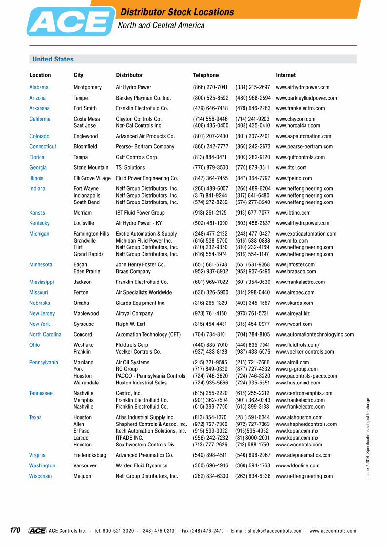
170
Issu
e 7.
2014
Spe
cific
atio
ns s
ubje
ct to
cha
nge
ACE Controls Inc. · Tel. 800-521-3320 · (248) 476-0213 · Fax (248) 476-2470 · E-mail: [email protected] · www.acecontrols.com
Distributor Stock LocationsNorth and Central America
Location City Distributor Telephone Internet
Alabama Montgomery Air Hydro Power (866) 270-7041 (334) 215-2697 www.airhydropower.com
Arizona Tempe Barkley Playman Co. Inc. (800) 525-8592 (480) 968-2594 www.barkleyfluidpower.com
Arkansas Fort Smith Franklin Electrofluid Co. (479) 646-7448 (479) 646-2263 www.frankelectro.com
California Costa Mesa Clayton Controls Co. (714) 556-9446 (714) 241-9203 www.claycon.com Sant Jose Nor-Cal Controls Inc. (408) 435-0400 (408) 435-0410 www.norcal4air.com
Colorado Englewood Advanced Air Products Co. (801) 207-2400 (801) 207-2401 www.aapautomation.com
Connecticut Bloomfield Pearse- Bertram Company (860) 242-7777 (860) 242-2673 www.pearse-bertram.com
Florida Tampa Gulf Controls Corp. (813) 884-0471 (800) 282-9120 www.gulfcontrols.com
Georgia Stone Mountain TSI Solutions (770) 879-3500 (770) 879-3511 www.4tsi.com
Illinois Elk Grove Village Fluid Power Engineering Co. (847) 364-7455 (847) 364-7797 www.fpeinc.com
Indiana Fort Wayne Neff Group Distributors, Inc. (260) 489-6007 (260) 489-6204 www.neffengineering.com Indianapolis Neff Group Distributors, Inc. (317) 841-9244 (317) 841-6480 www.neffengineering.com South Bend Neff Group Distributors, Inc. (574) 272-8282 (574) 277-3240 www.neffengineering.com
Kansas Merriam IBT Fluid Power Group (913) 261-2125 (913) 677-7077 www.ibtinc.com
Kentucky Louisville Air Hydro Power - KY (502) 451-1000 (502) 456-2837 www.airhydropower.com
Michigan Farmington Hills Exotic Automation & Supply (248) 477-2122 (248) 477-0427 www.exoticautomation.com Grandville Michigan Fluid Power Inc. (616) 538-5700 (616) 538-0888 www.mifp.com Flint Neff Group Distributors, Inc. (810) 232-9350 (810) 232-4169 www.neffengineering.com Grand Rapids Neff Group Distributors, Inc. (616) 554-1974 (616) 554-1197 www.neffengineering.com
Minnesota Eagan John Henry Foster Co. (651) 681-5738 (651) 681-9368 www.jhfoster.com Eden Prairie Braas Company (952) 937-8902 (952) 937-6495 www.braasco.com
Mississippi Jackson Franklin Electrofluid Co. (601) 969-7022 (601) 354-0630 www.frankelectro.com
Missouri Fenton Air Specialists Worldwide (636) 326-5900 (314) 298-0440 www.airspec.com
Nebraska Omaha Skarda Equipment Inc. (316) 265-1329 (402) 345-1567 www.skarda.com
New Jersey Maplewood Airoyal Company (973) 761-4150 (973) 761-5731 www.airoyal.biz
New York Syracuse Ralph W. Earl (315) 454-4431 (315) 454-0977 www.rwearl.com
North Carolina Concord Automation Technology (CFT) (704) 784-8101 (704) 784-8105 www.automationtechnologyinc.com
Ohio Westlake Fluidtrols Corp. (440) 835-7010 (440) 835-7041 www.fluidtrols.com/ Franklin Voelker Controls Co. (937) 433-8128 (937) 433-6076 www.voelker-controls.com
Pennsylvania Mainland Air Oil Systems (215) 721-9595 (215) 721-7666 www.airoil.com York RG Group (717) 849-0320 (877) 727-4332 www.rg-group.com Houston PACCO - Pennsylvania Controls (724) 746-3620 (724) 746-3220 www.pacontrols-pacco.com Warrendale Huston Industrial Sales (724) 935-5666 (724) 935-5551 www.hustonind.com
Tennessee Nashville Centro, Inc. (615) 255-2220 (615) 255-2212 www.centromemphis.com Memphis Franklin Electrofluid Co. (901) 362-7504 (901) 362-0343 www.frankelectro.com Nashville Franklin Electrofluid Co. (615) 399-7700 (615) 399-3133 www.frankelectro.com
Texas Houston Atlas Industrial Supply Inc. (813) 854-1370 (281) 591-6344 www.aishouston.com Allen Shepherd Controls & Assoc. Inc. (972) 727-7300 (972) 727-7363 www.shepherdcontrols.com El Paso Itech Automation Solutions, Inc. (915) 599-3022 (915)595-4952 www.kopar.com.mx Laredo ITRADE INC. (956) 242-7232 (81) 8000-2001 www.kopar.com.mx Houston Southwestern Controls Div. (713) 777-2626 (713) 988-1750 www.swcontrols.com
Virginia Fredericksburg Advanced Pneumatics Co. (540) 898-4511 (540) 898-2067 www.advpneumatics.com
Washington Vancouver Warden Fluid Dynamics (360) 696-4946 (360) 694-1768 www.wfdonline.com
Wisconsin Mequon Neff Group Distributors, Inc. (262) 834-6300 (262) 834-6338 www.neffengineering.com
United States

Issu
e 7.
2014
Spe
cific
atio
ns s
ubje
ct to
cha
nge
2 171
Distributor Stock LocationsNorth and Central America
Major Customers
ACE Controls Inc. · Tel. 800-521-3320 · (248) 476-0213 · Fax (248) 476-2470 · E-mail: [email protected] · www.acecontrols.com ACE Controls Inc. · Tel. 800-521-3320 · (248) 476-0213 · Fax (248) 476-2470 · E-mail: [email protected] · www.acecontrols.com
Canada
Central America
Location City Distributor Telephone Internet
British Columbia Burnaby Peerless Engineering Sales Ltd. (604) 659-4100 (604) 659-4121 www.peerlesse.com
Ontario Stoney Creek Vickers-Warnick Limited (905) 643-1448 (905) 643-9785 www.vickers-warnick.com
Quebec Lachine Cowper Incorporated (514) 637-6746 (514) 637-5055 www.copwer.ca
Location City Distributor Telephone Internet
Costa Rica San José Grupo Kopar (81) 8000-2000 (81) 8000-2001 www.kopar.com.mx
Mexico Monterrey Grupo Kopar (81) 8000-2000 (81) 8000-2001 www.kopar.com.mx
Puerto Rico Caguas P & C Company (787) 768-5033 (787) 744-8306 N/A San Juan Rafael Benitez Carrillo, (787) 725-7635 (787) 723-1257 http://web.applied.com/ Inc./Applied Ind. base.cfm?page_id=2754
Issu
e 7.
2014
Spe
cific
atio
ns s
ubje
ct to
cha
nge

Indu
stria
l Sho
ck A
bsor
bers Automation Control Equipment
USA ACE CONTROLS INC.
23435 Industrial Park Dr., Farmington HillsMI 48335, USA Tel.: +1-248-476-0213Fax: +1-248-476-2470www.acecontrols.com
GERMANY ACE STOSSDÄMPFER GMBH
Albert-Einstein-Straße 1540764 Langenfeld, GermanyTel.: +49-(0) 2173-9226-10Fax: +49-(0) 2173-9226-19www.ace-ace.de
GREAT BRITAIN ACE CONTROLS INTERNATIONAL
Unit 404 Easter Park, Haydock LaneHaydock, WA11 9TH, U.K.Tel.: +44-(0) 1942 727440Fax: +44-(0) 1942 717273www.ace-controls.co.uk
JAPAN ACE CONTROLS JAPAN L.L.C.
City Center Bldg. II 2fl 3-1-42, Chigasaki-minami, Tsuzuki-ku Yokohama, 224-0037, JapanTel.: +81-(45) 945-0123Fax: +81-(45) 945-0122 www.acecontrols.co.jp
P.R. CHINA ACE CONTROLS (SUZHOU) CO. LTD.
Building 7 East, No. 369 Lushan Road, SuzhouJiangsu Province 215129, P. R. ChinaTel.: +86-(512) 88606699Fax: +86-(512) 88606698www.acecontrols.cn.com
Distributors in other countries see pages 170 and 171.
Editi
on 7
/201
4
Sales Locations
ACE Controls Inc. 23435 Industrial Park Dr., Farmington Hills, MI 48335Tel. +1- 248 - 476-0213 · Fax +1- 248 - 476-2470 · [email protected] · www.acecontrols.com
IndustrialShock Absorbers
SafetyShock Absorbers
TUBUSProfile Dampers
Dampers/Feed Controls
IndustrialGas Springs
Main CatalogEdition 7/2014
New Models
New Models
New Models


![Accumulo Summit 2015: Ferrari on a Bumpy Road: Shock Absorbers to Smooth Out Accumulo Performance [Performance]](https://img.dokumen.tips/doc/110x75/55a5e4181a28ab37368b4773/accumulo-summit-2015-ferrari-on-a-bumpy-road-shock-absorbers-to-smooth-out-accumulo-performance-performance.jpg)