Embed Size (px)
Citation preview

SAFETY & TRANSPORT FIRE RESEARCH
Fire Safety of Lithium-Ion Batteries in Road Vehicles
Roeland Bisschop, Ola Willstrand, Francine Amon, Max Rosengren RISE Report 2019:50

© RISE Research Institutes of Sweden
Fire Safety of Lithium-Ion Batteries in Road Vehicles
Roeland Bisschop, Ola Willstrand, Francine Amon, Max Rosengren

2
© RISE Research Institutes of Sweden
Abstract The demand for lithium-ion battery powered road vehicles continues to increase around the world. As more of these become operational across the globe, their involvement in traffic accidents and fire incidents is likely to rise. This can damage the lithium-ion battery and subsequently pose a threat to occupants and responders as well as those involved in post-crash operations. There are many different types of lithium-ion batteries, with different packaging and chemistries but also variations in how they are integrated into modern vehicles. To use lithium-ion batteries safely means to keep the cells within a defined voltage and temperature window. These limits can be exceeded as a result of crash or fault conditions. This report provides background information regarding lithium-ion batteries and battery pack integration in vehicles. Fire hazards are identified and means for preventing and controlling them are presented. The possibility of fixed fire suppression and detection systems in electric vehicles is discussed.
Key words: Lithium-Ion Batteries, Electric Vehicles, Fire Risks, Post-Crash Handling, Risk Management, Fire Safety
RISE Research Institutes of Sweden AB
RISE Report 2019:50 ISBN: 978-91-88907-78-3 Borås 2019
Cover image: A collage of four different images. Burning heavy truck on a highway, burning passenger car in an urban area, passenger cars in dense traffic, bus travelling through an urban area.

3
© RISE Research Institutes of Sweden
Acknowledgements The project (No. 45629-1) is financed by the Swedish FFI-program (Strategic Vehicle Research and Innovation) which is a partnership between the Swedish government and the automotive industry. Partners within this project comprise of RISE Research Institutes of Sweden, Scania, Volvo Buses, SFVF (Swedish Association of Vehicle Workshops), Fogmaker International and Dafo Vehicle Fire Protection. All support in the project is gratefully acknowledged.

4
© RISE Research Institutes of Sweden
Content Abstract ..................................................................................................... 2
Acknowledgements .................................................................................... 3 Content ...................................................................................................... 4
1 Introduction ........................................................................................ 6
2 Electric Road Vehicles .......................................................................... 7
2.1 Statistics................................................................................................................... 7 2.2 Vehicle Configurations .......................................................................................... 10
2.3 Plug-In Charging ................................................................................................... 14
3 Lithium-Ion Batteries ......................................................................... 15
3.1 Packaging ............................................................................................................... 15
3.2 The Electrochemical Cell ....................................................................................... 17 3.2.1 Electrolyte ...................................................................................................... 18
3.2.2 Separator ........................................................................................................ 19
3.3 Lithium-Ion Batteries in Road Vehicles ............................................................... 20
3.3.1 Lithium-Ion Battery Packs, Modules and Cells ............................................ 20
3.3.2 Passenger Cars with Lithium-Ion Batteries ................................................... 21
3.3.3 Heavy Vehicles with Lithium-Ion Batteries .................................................. 26
4 Fire Risks Associated with Lithium-Ion Batteries .............................. 30
4.1 Thermal Runaway ................................................................................................ 30
4.2 Battery Failure Causes .......................................................................................... 32
4.2.1 Internal Cell Short Circuit ............................................................................. 33
4.2.2 Mechanical Deformation and Impact ........................................................... 34
4.2.3 Charge ........................................................................................................... 36
4.2.4 Discharge ........................................................................................................ 37
4.2.5 External Short Circuit ................................................................................... 38
4.2.6 Exposure to High Temperatures ................................................................... 39
4.3 Hazards and Risk Factors ..................................................................................... 40
4.3.1 Chemistry ....................................................................................................... 41
4.3.2 State of Charge and Cell Capacity ................................................................. 42
4.3.3 Thermal Propagation .................................................................................... 44
4.4 Challenges for Responders ................................................................................... 45
4.4.1 Identifying Electric Vehicles ......................................................................... 45
4.4.2 Toxicity of Vented Gases and Fire Water Run-Off ........................................ 46
4.4.3 Fibre Composite Materials .............................................................................47
5 Collisions and Fires ............................................................................ 48 5.1 Documented Incidents ......................................................................................... 48
5
© RISE Research Institutes of Sweden
5.1.1 Trends and Statistics ..................................................................................... 50
5.2 Handling of Damaged Electric Vehicles ................................................................ 51 5.2.1 Fire Hazards .................................................................................................. 52
5.2.2 Electrical Hazards ......................................................................................... 56
6 Safety Solutions ................................................................................. 59
6.1 A Holistic View ..................................................................................................... 59
6.1.1 Battery Cell Level ........................................................................................... 60
6.1.2 Battery Management System (BMS) ............................................................. 60
6.1.3 Battery Module Level .................................................................................... 62
6.1.4 Battery Pack Level ......................................................................................... 62
6.1.5 Vehicle Level ................................................................................................. 63
6.2 Fixed Fire Detection and Suppression Systems ................................................... 64
6.2.1 Detection ....................................................................................................... 64
6.2.2 Suppression ................................................................................................... 65
6.3 Hazard Identification Workshop .......................................................................... 68 6.3.1 Method .......................................................................................................... 68
6.3.2 Results ........................................................................................................... 69
7 Conclusions ........................................................................................ 71
8 References .......................................................................................... 72
Appendix A, Documentation from Workshop ........................................... 91
Prevention ..................................................................................................................... 91
Recovery ....................................................................................................................... 98
Appendix B, Participants of Workshop ................................................... 104

6
© RISE Research Institutes of Sweden
1 Introduction The demand for electric vehicles (EVs) continues to increase around the world. This is largely due to regulations related to air quality and environmental issues in combination with consumer demand and cheaper rechargeable energy storage systems. Furthermore, significant developments have made these storage systems, especially those belonging to the lithium-ion family, suited for automotive applications [1].
As more lithium-ion battery (LIB) powered road vehicles become operational across the globe, their involvement in traffic accidents is likely to rise. As for conventionally fuelled vehicles, the on-board energy storage system is a risk factor for those involved in, or responding to, accidents. While the risks associated with conventional vehicles are well-defined and generally accepted by society; time and education are needed to achieve this comfort level for LIB powered road vehicles. When it comes to EVs there is a risk that the LIB may ignite after significant amounts of time after being damaged or reignite after having been extinguished. This matter not only concerns firefighters, but also those involved in handling damaged EVs through towing, workshop, scrapyard or recycling activities.
This RISE report, part of current project (No. 45629-1), addresses these and other concerns through a review of available literature. Fundamental information on EVs and LIBs is presented, and matters related to fire risks and safety solutions are investigated. This provides a scientific basis to those who seek to develop their own guidelines and routines for handling risks associated with LIBs in road vehicles.
Current project will continue to investigate and develop relevant risk management routines and evaluate fire suppression and emergency cooling systems. For the latter, full-scale experiments will be performed to evaluate if they can enhance safety when integrated into LIBs.

7
© RISE Research Institutes of Sweden
2 Electric Road Vehicles Over the last few years there has been a continuous and strong increase in the number of electric vehicles on our roads. This is largely due to regulations related to air quality and environmental issues in combination with consumer demand and cheaper rechargeable energy storage systems. Furthermore, significant developments have made these storage systems, especially those belonging to the lithium-ion family, suited for automotive applications [1].
However, the shift to new and different means of transport and infrastructure is accompanied by new risks. It is thus important to have a basic understanding about these vehicles as their involvement in traffic accidents is likely to increase. This chapter addresses this by providing background information needed to understand electric vehicles. Specific topics include statistics related to the growing number of electric vehicles as well as their operating principles and fuelling mechanisms. Together they provide basic insight into the scope of their market penetration and the unique features that set them apart from other vehicles.
2.1 Statistics Data from the International Energy Agency up to 2017, presented in Figure 1, shows that most of the passenger cars in the world can be found in the Peoples Republic of China (China), the European Union (EU) and the United States of America (US) [2]. In 2017, approximately 40 % of all electric passenger cars in the world could be found driving around in China. Coming in second is the EU with roughly 870 000 electric passenger cars. This is relatively close to the US, where 760 000 electric passenger cars were recorded for the same year.
Figure 1 The uptake of electric passenger cars is dominated by China, the US, and the EU [2].
0
500
1000
1500
2000
2500
3000
3500
Num
ber
of e
lect
ric
pass
enge
r ca
rs
x 10
00
Total
China
US
EU

8
© RISE Research Institutes of Sweden
Figure 2 shows how the number of electric passenger cars in the Nordic countries compare to the rest of the EU according to the European Alternative Fuels Observatory [3]. Together, the Nordic countries represent the largest market for electric vehicles in the EU, with most purchases made in Norway and Sweden [4]. The country that stands out the most is Norway. In 2018, approximately half of all passenger cars sold in Norway were electric [3]. This is much higher than other Nordic countries, where electric passenger cars sold in Sweden, Denmark, Finland and Iceland comprised about 8%, 2%, 5% and 20% of all new cars sold in 2018, respectively [3].
Figure 2 The growth in electric passenger cars in Europe and the Nordic countries [3]
Other vehicle types, such as buses are experiencing similar trends as those observed for passenger cars, see Figure 3. Currently, this shift is particularly evident for public transportation solutions in large cities. Influencing factors in this are the cost and weight of lithium-ion battery packs. Specifically, smaller batteries can be used in local and city traffic as due to the short routes and frequent stops. In contrast, long haul buses, such as coaches, require very large and heavy batteries or require continuous charging. It is thus no surprise that the current growth has been most significant in metropolitan areas.
Figure 3 Number of electric buses operating in the European Union [5].
0
200
400
600
800
1000
1200
Num
ber
of e
lect
ric
pass
enge
r ca
rs x
100
0
EU
Norway
Sweden
Denmark
Finland
Iceland
0
400
800
1200
1600
2000
Num
ber
of e
lect
ric
buse
s
EU
Netherlands
Germany
Nordic 5
Austria
France
9
© RISE Research Institutes of Sweden
Similar trends are seen when it comes to transportation of goods by electric heavy trucks. Rechargeable energy storage systems, such as lithium-ion batteries, are still less energy-dense than fossil-fuel1. This means that a significant charging infrastructure and/or development in battery technology is needed to sustain continues operation over long distances. They are currently more suited to short distance delivery in metropolitan areas. A good example are heavy trucks used to deliver goods inside metropolitan areas or services to and from ports and rail yards. Typically, these heavy trucks drive short distances with frequent stops for loading, unloading and charging. This makes them suitable candidates for electrification.
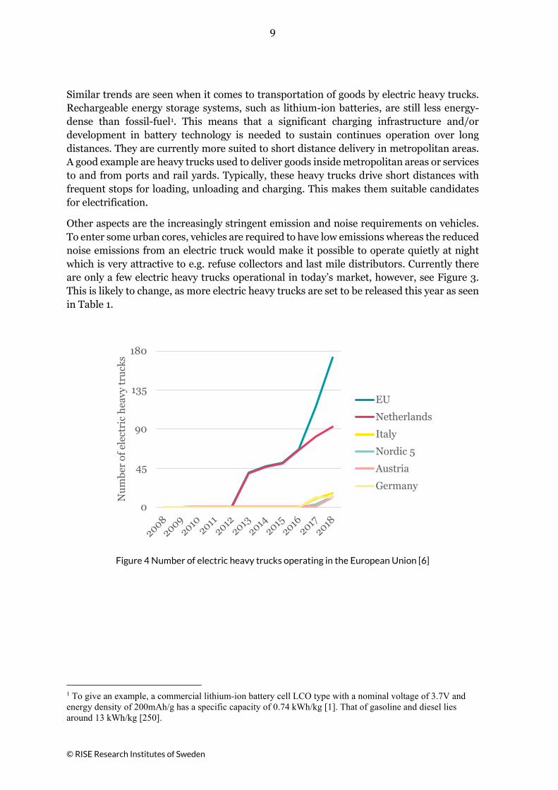
Other aspects are the increasingly stringent emission and noise requirements on vehicles. To enter some urban cores, vehicles are required to have low emissions whereas the reduced noise emissions from an electric truck would make it possible to operate quietly at night which is very attractive to e.g. refuse collectors and last mile distributors. Currently there are only a few electric heavy trucks operational in today’s market, however, see Figure 3. This is likely to change, as more electric heavy trucks are set to be released this year as seen in Table 1.
Figure 4 Number of electric heavy trucks operating in the European Union [6]
1 To give an example, a commercial lithium-ion battery cell LCO type with a nominal voltage of 3.7V and energy density of 200mAh/g has a specific capacity of 0.74 kWh/kg [1]. That of gasoline and diesel lies around 13 kWh/kg [250].
0
45
90
135
180
Num
ber
of e
lect
ric
heav
y tr
ucks
EU
Netherlands
Italy
Nordic 5
Austria
Germany
10
© RISE Research Institutes of Sweden
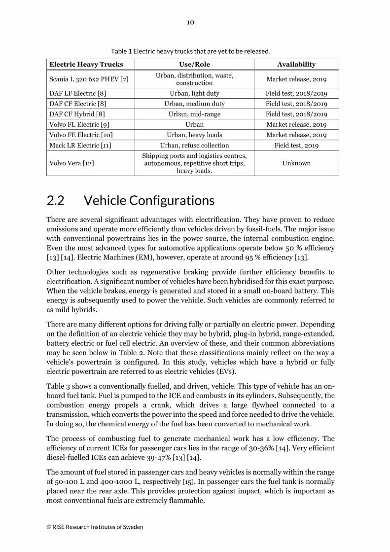
Table 1 Electric heavy trucks that are yet to be released.
Electric Heavy Trucks Use/Role Availability
Scania L 320 6x2 PHEV [7] Urban, distribution, waste, construction Market release, 2019
DAF LF Electric [8] Urban, light duty Field test, 2018/2019
DAF CF Electric [8] Urban, medium duty Field test, 2018/2019
DAF CF Hybrid [8] Urban, mid-range Field test, 2018/2019
Volvo FL Electric [9] Urban Market release, 2019
Volvo FE Electric [10] Urban, heavy loads Market release, 2019
Mack LR Electric [11] Urban, refuse collection Field test, 2019
Volvo Vera [12] Shipping ports and logistics centres, autonomous, repetitive short trips,
heavy loads. Unknown
2.2 Vehicle Configurations There are several significant advantages with electrification. They have proven to reduce emissions and operate more efficiently than vehicles driven by fossil-fuels. The major issue with conventional powertrains lies in the power source, the internal combustion engine. Even the most advanced types for automotive applications operate below 50 % efficiency [13] [14]. Electric Machines (EM), however, operate at around 95 % efficiency [13].
Other technologies such as regenerative braking provide further efficiency benefits to electrification. A significant number of vehicles have been hybridised for this exact purpose. When the vehicle brakes, energy is generated and stored in a small on-board battery. This energy is subsequently used to power the vehicle. Such vehicles are commonly referred to as mild hybrids.
There are many different options for driving fully or partially on electric power. Depending on the definition of an electric vehicle they may be hybrid, plug-in hybrid, range-extended, battery electric or fuel cell electric. An overview of these, and their common abbreviations may be seen below in Table 2. Note that these classifications mainly reflect on the way a vehicle’s powertrain is configured. In this study, vehicles which have a hybrid or fully electric powertrain are referred to as electric vehicles (EVs).
Table 3 shows a conventionally fuelled, and driven, vehicle. This type of vehicle has an on-board fuel tank. Fuel is pumped to the ICE and combusts in its cylinders. Subsequently, the combustion energy propels a crank, which drives a large flywheel connected to a transmission, which converts the power into the speed and force needed to drive the vehicle. In doing so, the chemical energy of the fuel has been converted to mechanical work.
The process of combusting fuel to generate mechanical work has a low efficiency. The efficiency of current ICEs for passenger cars lies in the range of 30-36% [14]. Very efficient diesel-fuelled ICEs can achieve 39-47% [13] [14].
The amount of fuel stored in passenger cars and heavy vehicles is normally within the range of 50-100 L and 400-1000 L, respectively [15]. In passenger cars the fuel tank is normally placed near the rear axle. This provides protection against impact, which is important as most conventional fuels are extremely flammable.

11
© RISE Research Institutes of Sweden
Table 2 Classification of electric road vehicles.
Vehicle 1st Motor 2nd Motor Acronym Electric Range2 [km] [16]
Power Source
Conventional vehicle
Internal combustion engine (ICE)
None ICEV 0 Fossil-fuel
Hybrid electric vehicle ICE
Electric machine
(EM) HEV 0 to 10
Fossil-fuel combined with
Lead-acid, NiMH or Li-ion
battery
Plug-in hybrid electric vehicle
ICE or electric
machine (EM)
EM or ICE PHEV 20 to 85 Fossil-fuel
combined with Li-ion battery
Range extended electric vehicle EM ICE REEV or
PHEV 75-145 Fossil fuel
combined with Li-ion battery
Battery electric vehicle EM None BEV 80 to 400 Li-ion battery
Fuel cell electric vehicle EM None FCEV 160 to 500
Fuel cell, can be combined with
Li-ion battery or supercapacitor
The BEV does not consume any fossil fuel or emit exhaust gas. The BEV powertrain primarily consists of a traction battery, electric machine and a transmission or final drive system. This can be seen in Table 4. At the heart of the BEV lies a lithium-ion traction battery. These have to be significant in size in order to achieve sufficient driving ranges. It takes up a lot more space than fuel tanks due as lithium-ion batteries generate less energy per weight unit than gasoline or diesel. Specifically, 0.1-0.2 kWh/kg versus more than 10 kWh/kg for conventional fuels. This also means that the TB make up a large portion of the vehicles total weight. For example, the battery pack in the Tesla Model S 85 makes up 30% of its total weight [17].
2 Indicative electric driving range for passenger cars.

12
© RISE Research Institutes of Sweden
Table 3 ICE configuration and system components
Figure 5 ICE configuration
System Application
ICE
The fuel combusts in the cylinders of the ICE, propelling a crank, which transfers combustion energy to mechanical work. Efficiency <50% [13] [14].
Gearing
Transfers mechanical work. Gearing refers to the transmission, differential, split drive and any other devices which transfer mechanical power.
Mechanical power
Typically, rotating shafts and axles due to an applied torque.
Fuel tank
Generally, for passenger cars, fuel tanks can store between 50 to 100 L of fuel whereas heavy vehicles such as trucks and buses store 400 to 1000 L of fuel [15].
Fuel line Typically, in the form of reinforced rubber hoses.
Fuel port
Port that connects to fuelling equipment in order to re-fill the fuel tank.
Table 4 BEV configuration and system components
Figure 6 BEV configuration
System Application
Traction battery
Stores electrical energy which can be released and made available to power the vehicle. Lithium-ion batteries (LIBs) are the preferred option for the traction batteries in PHEVs and BEVs.
Electric machine
Used as a traction motor and sometimes a generator [18]. Efficiency ~95% [13].
High
voltage cables
High voltage cables may be found between the battery and power electronics as well as between the power electronics and the electric machines. Their total weight may be up to 10 kg in hybrid passenger vehicles [18].
Battery charger
Electrical power grids provide AC current and batteries can only store DC current. The electricity thus needs to be converted. This is achieved by either an on-board AC/DC converter or by a converter integrated into the charging station itself [18].
In the automotive industry, hybrids are vehicles that have an electric powertrain as well as an ICE system. Doing so allows for significant fuel savings. It allows for regenerative braking, smaller engines and more efficient operating conditions, as well as the ability for engine shut-off when idling or at low load conditions [17].

13
© RISE Research Institutes of Sweden
There are different types of hybrids on the market. They can be classified as series, parallel, or series/parallel hybrids. Each of these has its advantages and disadvantages. Series hybrids operate on the electric machine. They have a large TB and small IC [17]. As seen in Figure 7 there is no mechanical connection between the ICE and the wheels. This allows the ICE to continuously operate at its most efficient engine speeds.
Parallel hybrids have the option to be powered by the EM or ICE independently, or to employ them simultaneously, see Figure 8. In this case there is a direct connection between the ICE, the transmission, and the final drive. These conditions give efficient driving at highway speeds. Usually parallel hybrids have a large ICE and a small TB [17].
Split hybrids, also referred to as series/parallel, combine the best of these configurations. As can be seen from Figure 9, they allow for vehicles to be powered directly by the ICE, with the EM assisting, or for the ICE to power a generator that powers the EM. This greater flexibility does generally come at a higher cost and with a more complex vehicle design.
Plug-in hybrids (PHEVs) follow these principles to the same extent HEVs do. The main difference is that PHEVs have larger batteries and therefore greater electric driving ranges. Energy generating systems such as regenerative braking is not enough to charge these large batteries hence external charging is needed.
Table 5 Hybrid configurations and system components
Figure 7 Series hybrid
Figure 8 Parallel hybrid
Figure 9 Split hybrid
Propulsion power
converters
Converts power from AC/DC or DC/AC. The DC/AC converter is located between the battery and electric motor. Hybrid vehicles are also equipped with an AC/DC converter between the generator and the traction battery [18].
DC/DC converter
Converter which connects to a 12V battery (passenger cars) that powers auxiliary equipment. In electric vehicles this battery is charged by the traction battery [18].

14
© RISE Research Institutes of Sweden
2.3 Plug-In Charging As for conventional vehicles, the driving range of EVs is limited by its fuel. In this case however, rather than filling the fuel tank with liquid, the battery must be supplied with electricity. There are three different ways of doing this, i.e. by swapping the battery with a fully charged one, charging wirelessly, or plug-in charging.
Plug-in charging is used to charge the vast majority of EVs in Europe [16]. Charging occurs by physically connecting a power cable from the EV to the grid. There is an international standard for conductive charging systems for EVs, namely IEC 61851. This standard defines four charging modes.
The first charging mode, mode 1, considers the EV to be connected to the grid by using common household sockets and cables. The current that is supplied is very limited [16]. In addition to this, there are no protective systems [19]. It is therefore not very relevant for EVs, and more commonly used to charge light vehicles, e.g. bicycles and scooters [20].
Mode 2 charging also considers charging through household sockets. This type of charging is considered slow or semi-fast [16]. A special cord is used with built-in charging equipment and this cord is equipped with a so-called pilot function and a circuit breaker. The pilot function detects the presence of the vehicle, communicates the maximum allowable charging current, and controls charging.
The third mode of charging connects the EV to a charging station via a special plug-socket. This type of charging is specifically designed for EVs and allows charging at higher power levels. In this case there is communication between the vehicle and the dedicated charging station, not with the cable. This type of charging has a high degree of safety as these protection systems are installed in the charging station itself. Among other things, the power supply must fulfil the requirements set by the on-board charger and those of the charging station. If not, there is no power transfer between the charging station and the EV.
The final charging mode, and the fastest one, is referred to as Mode 4. Here the EV is connected to the power grid through a charger inside an offboard charging station [21]. In this case, the control and protection functions as well as the charging cable are permanently installed in the charging station. The charging station itself converts AC power to DC power inside the charging station. For the other charging modes, this conversion is achieved with AC/DC converters that are inside the EV. As such, Mode 1 – 3 are sometimes referred to as on-board charging whereas Mode 4 is called off-board charging. Note that not all EVs allow for DC charging.

15
© RISE Research Institutes of Sweden
3 Lithium-Ion Batteries The energy of lithium-ion batteries (LIBs) is housed within individual battery cells. Each cell has one positive and one negative terminal. These terminals are connected to thin metal foil that has been coated with electrochemically active material. The active material for the negative and positive side of the battery is referred to as anode and cathode material, respectively. When the battery is discharged, electricity flows into the anode and out of the cathode, see Figure 10.
Depending on the cell geometry, the current collectors is pressed or rolled together with polymer separators and submerged in electrolyte. This is an electrically conductive media that allows for lithium-ions to be transported from one side to the other. The transfer of lithium-ions from one side to the other, through a separating material, results in chemical reactions that generate an electrical current. The direction of current depends on whether the battery is discharged or charged. In the case of charge, it flows from the anode to cathode, see Figure 10. The opposite happens when the battery is discharged.
Figure 10 Working principle of a lithium-ion battery when discharged.
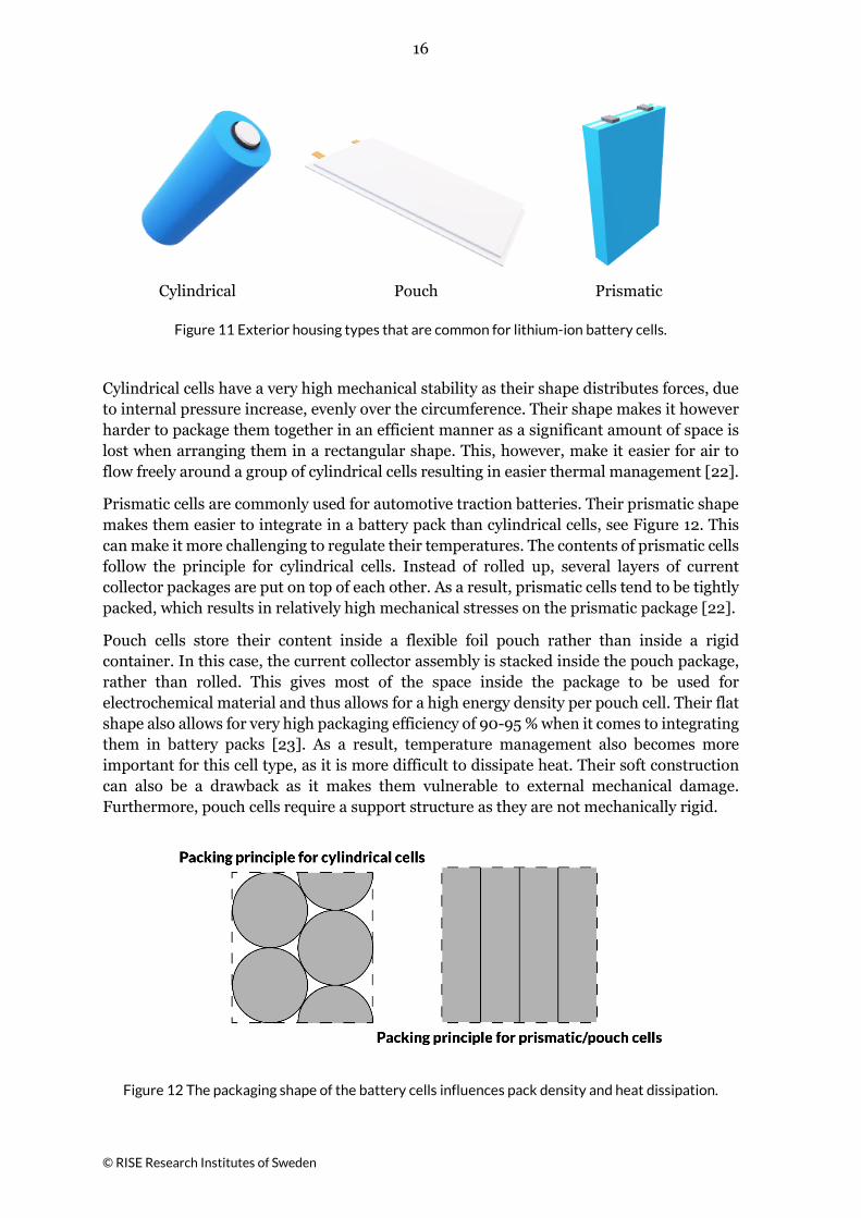
3.1 Packaging Packaging material is used to protect the electrochemical components of the lithium-ion battery cell. This packaging can be of different materials and shapes. They are usually distinguished by the shape of the package. As such, LIB cells are thus sometimes referred to as being cylindrical, prismatic or pouch cells. These are shown in Figure 11.
16
© RISE Research Institutes of Sweden
Cylindrical
Pouch
Prismatic
Figure 11 Exterior housing types that are common for lithium-ion battery cells.
Cylindrical cells have a very high mechanical stability as their shape distributes forces, due to internal pressure increase, evenly over the circumference. Their shape makes it however harder to package them together in an efficient manner as a significant amount of space is lost when arranging them in a rectangular shape. This, however, make it easier for air to flow freely around a group of cylindrical cells resulting in easier thermal management [22].
Prismatic cells are commonly used for automotive traction batteries. Their prismatic shape makes them easier to integrate in a battery pack than cylindrical cells, see Figure 12. This can make it more challenging to regulate their temperatures. The contents of prismatic cells follow the principle for cylindrical cells. Instead of rolled up, several layers of current collector packages are put on top of each other. As a result, prismatic cells tend to be tightly packed, which results in relatively high mechanical stresses on the prismatic package [22].
Pouch cells store their content inside a flexible foil pouch rather than inside a rigid container. In this case, the current collector assembly is stacked inside the pouch package, rather than rolled. This gives most of the space inside the package to be used for electrochemical material and thus allows for a high energy density per pouch cell. Their flat shape also allows for very high packaging efficiency of 90-95 % when it comes to integrating them in battery packs [23]. As a result, temperature management also becomes more important for this cell type, as it is more difficult to dissipate heat. Their soft construction can also be a drawback as it makes them vulnerable to external mechanical damage. Furthermore, pouch cells require a support structure as they are not mechanically rigid.
Figure 12 The packaging shape of the battery cells influences pack density and heat dissipation.

17
© RISE Research Institutes of Sweden
3.2 The Electrochemical Cell A LIB package consists of different electrochemical materials. These include anode, cathode, separator and electrolyte. Each of them plays a role in the batteries’ properties concerning specific energy, life, safety and cost.
The type of cathode material is often used to classify lithium-ion batteries in groups. This is mostly because their chemistry is one of the main variables in their construction. There are many different options available, see Table 6. Note that cathode types presented here only are a selection of the most common and commercialised types. For a more complete overview refer to Nitta et al. [1].
Lithium Cobalt Oxide (LCO), as seen in Table 6, is common in a very large number of consumer devices such as smartphones. It offers relatively high capacity and voltage compared to other cathode materials and it is relatively easy to manufacture [24]. There are however significant safety concerns, especially at high temperature and overcharge conditions.
Introducing new technologies, such as EVs, to a market dominated by conventionally fuelled vehicles comes with a major barrier, i.e. fear of the unknown. Compromising on safety and accepting the risk of EVs catching fire due to LIB failure, even when abused, is thus not an option. The automotive industry therefore generally avoids chemistries that are known to have low thermal stability. Instead, they opt for safer cathode materials such as Lithium Iron Phosphate (LFP), Lithium Nickel Manganese Cobalt Oxide (NMC), Lithium Manganese Oxide (LMO) or blends of different cathode materials.
Performance is the major influencing factor when manufacturers choose certain cathode materials while not making any compromises on safety. To achieve high-performance and fast acceleration, a battery needs to be able to supply a lot of power. When longer driving ranges are needed the focus shifts to achieving a high energy density. Normally both high power and high energy density are desirable and today NMC, or Lithium Nickel Cobalt Aluminium Oxide (NCA), paired with graphite anodes is the most common [25] [26].
The characteristics of cathode materials can be modified further by blending different cathode materials. Such materials are referred to as hybrid or blended cathode materials. This technology was developed by commercial automotive battery suppliers and consist of a mixture of two or more different active materials [27]. Blending allows for different cathode materials to complement each other. It combines the best properties of the individual active materials and helps to reduce the shortcomings of the parent materials. Julien et al. showed that drawbacks of LFP, i.e. relatively low energy density, could be overcome by blending it with NMC [28]. Simultaneously, the material had better thermal stability than NMC by itself, due to the positive influence of LFP.

18
© RISE Research Institutes of Sweden
Table 6 Overview of the properties of common cathode materials.
Specific Energy [29] Voltage at 50% SOC [29] Life [17] Safety [17] Cost [17]
LFP 160 Ah/kg 3.4 V High High Medium
LMO 100-120 Ah/kg 4 V Low Medium Low
LCO 155 Ah/kg 3.9 V Medium Low Medium
NCA 180 Ah/kg 3.7 V Medium Low High
NMC 160 Ah/kg 3.8 V High Medium High
The number of options when it comes to anode materials are more limited. There are two types of anode materials commercially available, namely those comprised of different carbon configurations and Lithium Titanate Oxide (LTO) [1]. The former offers a good balance between cost, availability, energy and power density as well as cycle life whereas the latter provides better performance when it comes to thermal stability, charge/discharge rate and cycle life but suffers when it comes to cost, cell voltage and cell capacity [1].
3.2.1 Electrolyte
The individual components inside LIBs are soaked in an electrically conductive solution referred to as electrolyte. This media allows for ions to be transported between the positive and negative electrodes. It plays a very large role in the safety and general performance of LIBs. There are many different types of compositions possible and available, yet not all of them are compatible with other battery components or able to hold charge.
The vast majority of electrolytes for LIBs are nonaqueous solutions [30] [31], i.e. water is not the solvent. Electrolytes used for LIBs normally consist of Lithium Hexafluorophosphate (LiPF6) salts and organic carbonate solvents such as Ethylene Carbonate (EC). The composition of the solutions has mostly remained the same over the last decade. Xu [31] argues that this is due to three key factors; the electrolyte components being very sensitive, additives having become more effective, and the fact that the battery industry has been reluctant to change the existing supply chain.
Electrolyte components for LIBs are sensitive. Their operating temperature is limited, and typically lies between -20 ºC and +50 ºC [32]. When exposed to environments that are not within this range of safe operation, they could be permanently damaged. This starts with decomposition reactions of the interphase layer between the anode and electrolyte, referred to as solid electrolyte interphase (SEI). Herstedt [33] found that the onset of these reactions is strongly dependent to the salt that is used. Electrolytes systems with lithium tetrafluoroborate (LiBF4) or lithium hexafluorophosphate (LiPF6) salts, these reactions start at around 60-80 ºC and 80-100 ºC, respectively. For lithium triflate (LiTf) and lithium bisimide (LiTFSI)3 systems the decomposition reactions start at 110-120 ºC and 125-135 ºC, respectively. This is potentially followed by other exothermic reactions inside the LIB.
3 Lithium bis(trifluoromethanesulfonyl)imide
19
© RISE Research Institutes of Sweden
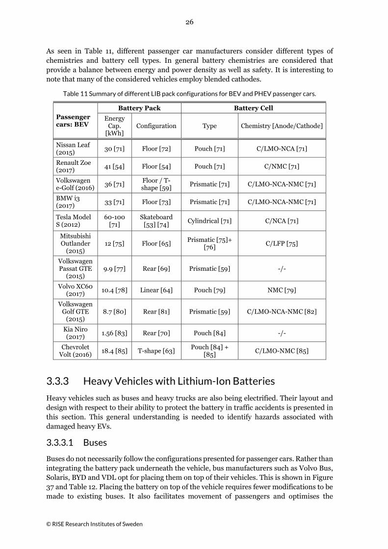
Another major issue with the current electrolytes considered for LIBs is its flammability. As seen in Table 7, not all electrolyte constituents are equally flammable. The most flammable solvent is Ethyl Acetate (EA). Among other things, this is due to the fact that it has a very low flashpoint. When exposed to temperatures below zero, EA releases enough vapour to sustain burning if ignited by a spark or flame. Note however that in comparison to gasoline, a convential fuel that has been around for more than a century, this solvent is relatively safe.
Additives and electrolyte components have been shown to be able to lower the flammability and slow down the thermal degradation of electrolyte [32]. Their main drawback is however that they can reduce performance [34]. Alternative electrolytes are being developed. Specifically, nonaqueous fluoro-compounds, ionic liquids and polymeric electrolytes [31] [25] [30]. None of these, except for certain polymeric electrolytes, have been commercialised on a large scale yet. The polymeric electrolytes currently available offer improved mechanical strength and less potential for leakage of toxic fluids [35] yet remain limited to the same safety window as conventional electrolyte [36].
Table 7 Flammability data for the electrolyte solvent in LIB cells and data for conventional automotive fuels for comparison.
Organic Electrolyte Solvents Boiling
Temperature [ºC]
Autoignition Temperature
[ºC]
Flash Point [ºC]
Flammable Limits, Lower /
Upper [%]
Ethyl Acetate (EA) [37] [38] 77 427 -3 2.2 / 9
Dimethyl Carbonate (DMC) [37] [38] 91 458 16 4.22 / 12.87
Ethyl Methyl Carbonate (EMC) [37] [38] 110 440 24 -/-
Diethyl Carbonate (DEC) [37] [38] 126 445 25 1.4 / 14.3
Ethylene Carbonate (EC) [37] [38] 248 465 143 3.6 / 16.1
Propylene Carbonate (PC) [37] [38] 242 455 132 1.8 / 14.3
Gasoline [39] 30 to 210 > 350 < -40 1.4 / 7.6
Diesel [40] >180 240 >61.5 0.7 / 5
3.2.2 Separator
The separator prevents the positive and negative electrode from contacting each other while enabling as many conducting ions as possible to flow through it. From a safety point of view, the former is very important. If the separator would be breached or contracts significantly, there is a risk that an internal short-circuit materialises. Weber et al. [41] therefore stress that separators must possess high strength characteristics, negligible thermal expansion and high melting point.
LIBs with organic electrolytes typically use microporous separators [42]. These can be fabricated from material such as polyethylene (PE) and polypropylene (PP) [43]. These

20
© RISE Research Institutes of Sweden
types of separators have a melting point around 125-130 ºC and 155-160 ºC, respectively [37] [44]. If the separator melts, the barrier between the positive and negative electrode is breached and an internal short circuit occurs, which may trigger a large heat output followed by uncontrollable chemical reactions and generation of massive amount of gas which could result in a cell case explosion if not vented [32] [44]. Separators may also be ceramic or composite based. This material offers improvement in terms of mechanical strength, thermal resistance, performance and cell life [41]. According to Nesler et al. [45] this technology needs more time to develop before it can be commonly used for EVs.
3.3 Lithium-Ion Batteries in Road Vehicles Lithium-ion batteries are the preferred energy storage solution for modern EVs. Their unmatched properties such as high cycle life, high energy density, and high efficiency makes them very suitable for automotive applications [1]. They can be small and be used for start-stop systems in EVs, or they can be much larger and used to power the powertrain.
Large battery packs are usually found in PHEVs and BEVs whereas HEVs require less energy capacity and thus fewer batteries. In this section the focus is vehicles that are designed to fit large battery packs. It is important to consider this as the examples given may not necessarily apply to, or be relevant for, HEVs.
3.3.1 Lithium-Ion Battery Packs, Modules and Cells
When speaking of LIB in the automotive industry there are several distinct levels of components that need to be understood. These are shown in Figure 13. The most basic level is the lithium-ion cell. Consumer devices such as smartphones usually consist of a single battery cell. Their voltage is thus restricted to what one cell can provide, i.e. roughly 4 V.
A much greater amount of stored energy can be obtained by connecting battery cells, and modules, together in series or parallel. LIB cells for automotive applications are normally connected together, in series and/or parallel, to form a module. The number of cells per module varies, but generally adds up to less than 60 V per module. Voltages greater than 30 VAC or 60 VDC are considered harmful for humans and defined as high voltages within the vehicle industry [21]. Restricting the voltage of battery modules is thus beneficial from a handling and shipping perspective. Finally, the battery modules are connected to form battery packs to meet the needed energy and power. Note that in some systems, several battery packs are coupled together to create the whole battery system. In doing so, applications such as passenger cars, heavy vehicles and electric ships can reach capacities around 10-100, 10-400 and 500-4000 kWh, respectively.

21
© RISE Research Institutes of Sweden
Figure 13 General construction of a battery pack.
3.3.2 Passenger Cars with Lithium-Ion Batteries
Many battery cells need to be integrated into an EV in order to achieve the needed power and energy. The overall goal in EV design is to achieve the largest possible battery pack while maintaining an appropriate safety level.
A common approach is to install the battery pack inside stiffened and reinforced compartments or areas less prone to be affected in crash conditions [46], see Figure 14 and Figure 15. The latter can be referred to as the “safe zone” of a passenger car [47]. This zone normally considers the area in the center of the chassis, between the wheelbase. By integrating the LIB pack in this area, automotive manufacturers aim to eliminate the possibility that the battery is affected by crash or impact conditions.
Figure 14 “Safe-zone” based on [48]
Figure 15 Battery layout for a Nissan Leaf [49]
For passenger cars there are three main configurations in which the “safe-zone” is utilized. Most common are the “Floor” and “T” configurations [50] where the battery is distributed in a square or rectangular area, as the one shown in Figure 16 or arranged in the shape of the letter “T” as seen in Figure 17. The third option can be referred to as the “Rear” solution illustrated by Figure 18. Here the battery pack is in the rear of the vehicle and in some cases stacked upwards.
Figure 16 The “Floor” solution
Figure 17 The “T” solution
Figure 18 The “Rear” solution

22
© RISE Research Institutes of Sweden
The “floor” type uses all of the available space in the “safe zone”. The entire battery pack is located underneath the passenger compartment. This provides more interior space for passengers and luggage but also allows for high energy storage. One of the drawbacks of this arrangement is that there is less ground clearance and that there is a larger target for ground debris [50]. See Table 8 for an overview of several EVs that consider the “Floor” configuration.
Table 8 Selection of EVs that employ the “Floor” solution to integrate their battery packs.
Nissan Leaf, EV Type: BEV Figure 19 and Figure 20 show the “floor” battery pack in the Nissan Leaf. The pack varies in its shape as more of the battery cells are placed underneath the front and rear seats. This model employs pouch cells in its battery pack. These flat cells are oriented horizontally, like a stack of paper, in the thinner sections of the pack. Underneath the seats they come up higher, as they are oriented vertically, like paper in a filing cabinet.
Figure 19 Nissan Leaf, copied from [51].
Figure 20 Battery pack, copied from [52]
Tesla Model S, EV Type: BEV The configuration found on Tesla’s is particularly flat in comparison to other vehicle models. Tesla refers to their solution as a “skateboard” battery pack. This thin pack ensures maximum available interior space.
Figure 21 Tesla Model S, copied from [53]
Renault Zoe, EV Type: BEV Figure 22 and Figure 23 show the battery pack of the Renault Zoe. This pack is located underneath the floor of the passenger compartment. The total capacity of this pack is 41 kWh at a weight of 300 kg [54], roughly 20% of the total weight of the vehicle.
Figure 22 Renault Zoe ZE40, copied from [54].
Figure 23 Battery pack, copied from [55]

23
© RISE Research Institutes of Sweden
BMW i3, EV Type BEV/PHEV The “Floor” solution for the BMW i3 may be seen in Figure 24. There are different versions available of this model, with one of them being a PHEV (or REEV). Normally, vehicles have their fuel tanks in between the rear wheels. As shown in Figure 25, this is not the case here. The fuel tank, indicated by the red arrow, is placed in front of the battery pack.
Figure 24 BMW i3, copied from [56]
Figure 25 REEV, copied from [57]
The “T” solution arranges the battery modules in a T-shape within the safe zone, as illustrated by Figure 17. This configuration allows for greater clearance between the ground and the battery pack. This is achieved by reducing the passenger area. It is rather narrow and usually protected by the front axle of the vehicle [58]. This ensures protection of the battery pack against frontal collision and side impact [50]. Several EVs with the T-shape, or similar configuration can be seen in Table 9.
The “Rear” solution makes use of the available space between the rear wheels of the vehicle. Typically, this type of configuration is found in small vehicles or hybrids, as they require less storage capacity. To increase the available energy, some EVs make use of the space behind or above the rear wheels. A selection of EVs that follow this configuration is seen in Table 10.
24
© RISE Research Institutes of Sweden
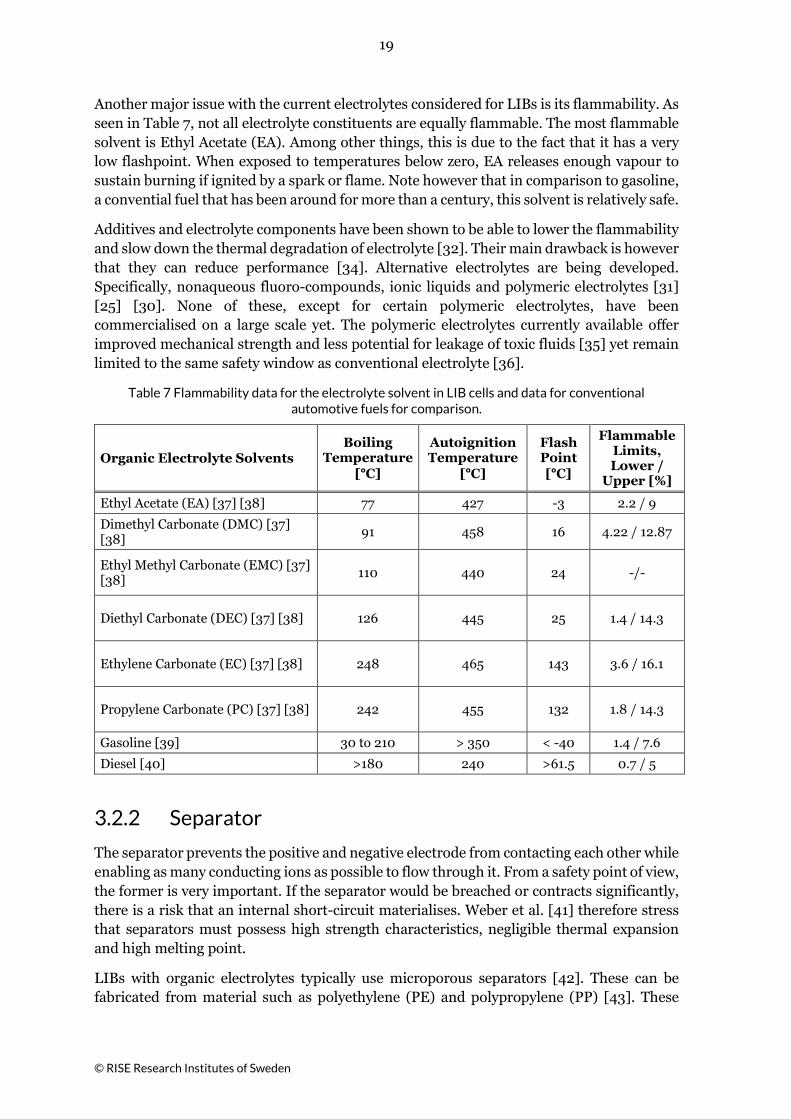
Table 9 Selection of EVs that employ the “T” solution to integrate their battery packs.
Volkswagen e-Golf, EV Type: BEV
Volkswagen combines a T-shape together with the space underneath the seats and floor for the battery pack in the Volkswagen e-Golf. This pack has an energy capacity of 24.2 kWh [59] and may be see in Figure 26 and Figure 27. This battery pack makes up a large portion of the vehicles total weight, namely 20 %.
Figure 26 Volkswagen e-Golf, copied from [60].
Figure 27 Battery pack, copied from [59].
Chevrolet Volt / Opel Ampere, EV Type: PHEV
The Chevrolet Volt (Opel Ampere in the EU [61]) may be seen in Figure 28 and Figure 29. The battery pack itself consist of vertically arranged pouch cells (e.g. paper in a filing cabinet).
Figure 28 Chevrolet Volt, copied from [62].
Figure 29 The battery pack, copied from [63].
Volvo XC60, EV Type: PHEV Mitsubishi Outlander, EV Type: PHEV
The battery pack in the Volvo XC60 PHEV is a variant of the “T” solution. In this case one part of the “T” is made up of the battery pack, and the other of the fuel tank, see Figure 30.
The configuration used in the Mitsubishi Outlander, seen in Figure 31, follows that of the Volvo XC60. Its design is less linear/rectangular, but it follows the same principle. That is that the “T” is made up of the battery pack and fuel tank combined.
Figure 30 Volvo XC60 PHEV, copied from [64]
Figure 31 Mitsubishi Outlander, copied from
[65].
25
© RISE Research Institutes of Sweden
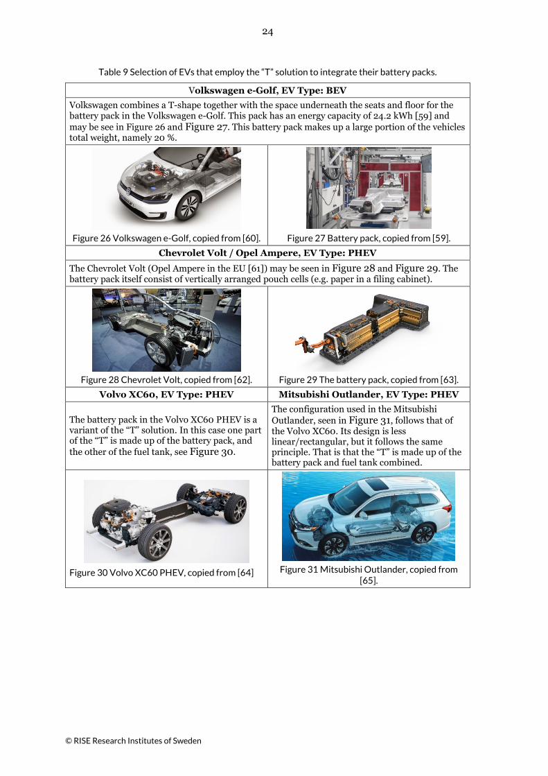
Table 10 Selection of EVs that employ the “Rear” solution to integrate their battery packs
Chevrolet Spark, EV Type: BEV As seen in Figure 32, the battery pack is located around the rear axle. The modules are positioned in a way that results into two modules being located underneath the rear seating area and two of them protruding from below the rear of the car booth, see Figure 33.
Figure 32 Chevrolet Spark, copied from [66]
Figure 33 Battery pack, copied from [67]
Mitsubishi Colt EV, EV Type: BEV
The battery pack for this vehicle is indicated by the arrow in Figure 34. It is positioned slightly in front of the rear axle.
Figure 34 Mitsubishi Colt EV, copied from [68]
Volkswagen Passat, EV Type: PHEV Kia Niro, EV Type PHEV In the cases seen in Figure 35 and Figure 36, a short yet wide battery pack is used. The pack itself is mounted in between the wheels, close to the rear axle. The fuel tank of these vehicles is installed closely behind this pack.
Figure 35 Volkswagen Passat, copied from [69].
Figure 36 Kia Niro PHEV, copied from [70]
26
© RISE Research Institutes of Sweden
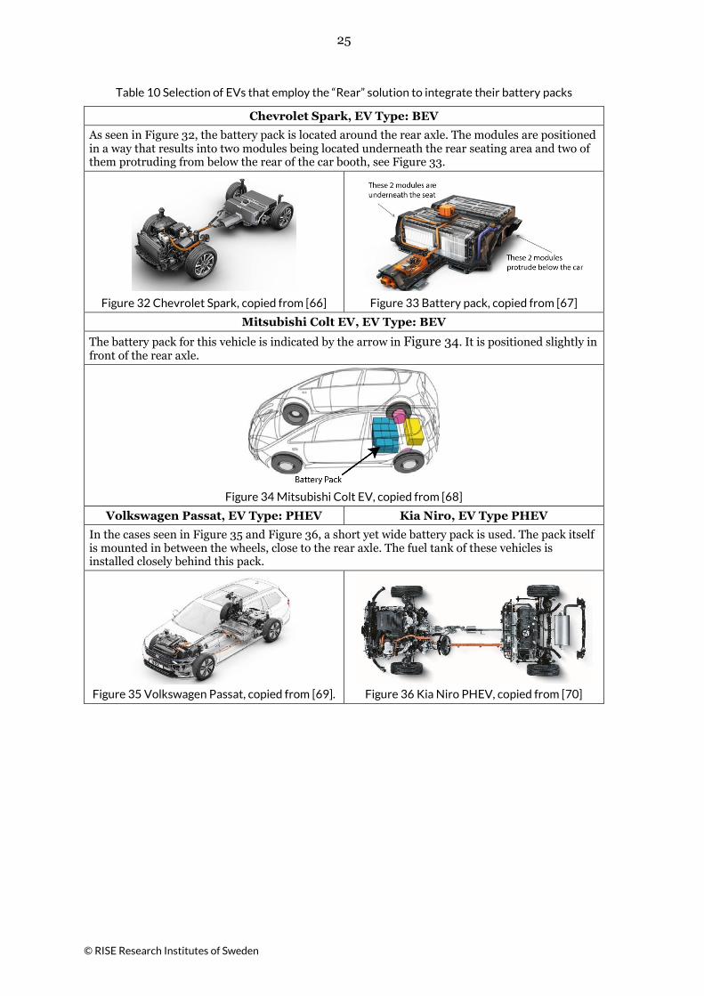
As seen in Table 11, different passenger car manufacturers consider different types of chemistries and battery cell types. In general battery chemistries are considered that provide a balance between energy and power density as well as safety. It is interesting to note that many of the considered vehicles employ blended cathodes.
Table 11 Summary of different LIB pack configurations for BEV and PHEV passenger cars.
Passenger cars: BEV
Battery Pack Battery Cell Energy
Cap. [kWh]
Configuration Type Chemistry [Anode/Cathode]
Nissan Leaf (2015) 30 [71] Floor [72] Pouch [71] C/LMO-NCA [71]
Renault Zoe (2017) 41 [54] Floor [54] Pouch [71] C/NMC [71]
Volkswagen e-Golf (2016) 36 [71] Floor / T-
shape [59] Prismatic [71] C/LMO-NCA-NMC [71]
BMW i3 (2017) 33 [71] Floor [73] Prismatic [71] C/LMO-NCA-NMC [71]
Tesla Model S (2012)
60-100 [71]
Skateboard [53] [74] Cylindrical [71] C/NCA [71]
Mitsubishi Outlander
(2015) 12 [75] Floor [65] Prismatic [75]+
[76] C/LFP [75]
Volkswagen Passat GTE
(2015) 9.9 [77] Rear [69] Prismatic [59] -/-
Volvo XC60 (2017) 10.4 [78] Linear [64] Pouch [79] NMC [79]
Volkswagen Golf GTE
(2015) 8.7 [80] Rear [81] Prismatic [59] C/LMO-NCA-NMC [82]
Kia Niro (2017) 1.56 [83] Rear [70] Pouch [84] -/-
Chevrolet Volt (2016) 18.4 [85] T-shape [63] Pouch [84] +
[85] C/LMO-NMC [85]
3.3.3 Heavy Vehicles with Lithium-Ion Batteries
Heavy vehicles such as buses and heavy trucks are also being electrified. Their layout and design with respect to their ability to protect the battery in traffic accidents is presented in this section. This general understanding is needed to identify hazards associated with damaged heavy EVs.
3.3.3.1 Buses
Buses do not necessarily follow the configurations presented for passenger cars. Rather than integrating the battery pack underneath the vehicle, bus manufacturers such as Volvo Bus, Solaris, BYD and VDL opt for placing them on top of their vehicles. This is shown in Figure 37 and Table 12. Placing the battery on top of the vehicle requires fewer modifications to be made to existing buses. It also facilitates movement of passengers and optimises the

27
© RISE Research Institutes of Sweden
occupant space. Other benefits include the fact that the batteries are easier exposed to air, allowing them to be cooled by the moving vehicle, and are more easily accessible for certain charging systems.
There are however some drawbacks of this strategy. Placing relatively heavy battery packs on top of a vehicle makes it more difficult to obtain a low centre of gravity. In addition, roof mounted solutions require protection from debris and moisture accumulation. This needs to be considered, as was illustrated by a recall of certain bus models in the US in 2011 [86].
Some buses do integrate the battery pack underneath the passenger space. An example of this is the Proterra Catalyst. Their battery pack is located below the floor of the bus as also seen in Table 12. In doing so this bus model can integrate enough batteries to obtain energy capacities of up to 660 kWh [87].
Chinese electric buses are also commonly equipped with a large number of batteries to achieve high energy capacities. An example of this is the BYD K9. This bus has been present in Europe since 2013. Its configuration is intended to supply enough energy storage capacity for full-day operation. They do not consider a “floor” configuration, instead they achieve a high capacity by integrating several different battery packs throughout the vehicle as seen in Figure 37 and Table 12.
The Volvo, VDL and Solaris buses reserve less space for their battery packs. As a result, their energy capacity is less than the BYD K9 and Proterra Catalyst. To sustain their operation, they rely on opportunity charging at e.g. bus-stops. One benefit of having fewer batteries is that the vehicle carries less weight. This can allow for lighter construction and greater efficiency.
The Optare Versa has its battery pack in the rear of the vehicle as also seen in Figure 37 and Table 12. This is a relatively simple installation when compared to the roof mounted option, as that method requires special fixtures and equipment.
Table 12 Battery packs in electric buses
Figure 37 Position of the battery packs on selected buses
BYD K9 A+C+E [88]
Volvo 7900 C [89]
VDL Citea B [90]
Solaris Urbino B [91]
Optare Versa D+E [92]
Proterra Catalyst
F [93] [94]

28
© RISE Research Institutes of Sweden
The types of batteries that are considered by the buses discussed in this section are presented in Table 13. Note that LFP chemistries appear to be relatively common for buses. LIBs of this chemistry have a lower energy capacity per kg than other chemistries such as NMC, which is common for electric passenger cars. There is however more space available on buses, hence this plays less of a role. The use of LFP cells allows them to reap the benefits of a more stable battery chemistry while still being able to achieve high energy and power densities.
Table 13 Selected electric bus models currently operating in Europe and their characteristics.
Buses: BEV or PHEV
Battery Pack Battery Cell Energy Capacity
[kWh] Configuration Type Anode/Cathode
Volvo 7900
76 [95] 150 - 250 [96]
Roof (rear) [89] - -/LFP
BYD K9 216-345 [97] Roof (rear) + rear and front [88] Prismatic [98] -/LFP [99]
Solaris Urbino 80-240 [91] Roof (front) [91] Pouch [100] LTO/- [101]
VDL Citea 60-250 [90] Roof (front) [90]
Prismatic [90] + [102]
or Pouch [90] + [103]
LTO/- or -/LFP [90]
Optare Versa 92-138 [104] Rear [92]
Cylindrical [105] + [106]
-/Lithium Iron Magnesium Phosphate
[92]
Proterra Catalyst
94 -440 (35 ft.) [107] 94 -660 (40 ft.) [87]
Floor [94] - -
3.3.3.2 Heavy Trucks
There are not a lot of heavy trucks with lithium-ion batteries on the market yet. Therefore, only limited data is available on how lithium-ion battery packs are integrated, see Table 14.
Contrary to buses, the placement of battery packs in heavy trucks appears to be more restricted. To give an example, consider the Scania L 320 6x2 PHEV [5] heavy truck. Here the battery pack is located behind the front wheel axle on the side of the driver. A similar configuration may be found in the electric heavy trucks that were announced by DAF this year [6]. Their press release images [21] show that the two battery packs used in the full electric models are located behind the front axle. One of them is located on the driver side and the other on the passenger side, see Figure 38. The hybrid DAF LE Hybrid has a single battery pack. In this case the fuel tank and battery pack are mounted on opposite sides of the driveshaft.
Lithium-ion batteries may potentially be integrated in truck trailers in the future. Some companies are working on developing truck trailers with solar panels. Their idea is to store excess energy produced by these panels in lithium-ion batteries [108]. This energy can then be used e.g. to power refrigerated trailers.

29
© RISE Research Institutes of Sweden
Table 14 Selected heavy truck models and their battery pack characteristics.
Heavy Trucks: BEV or PHEV
Battery Pack Energy Capacity [kWh] Configuration
Scania L 320 6x2 [7] 18.4 (limited to 7.4) Behind front wheel axle, left side of the vehicle.
DAF LF Electric [8] Up to 222 -
DAF CF Electric [8] 170 Behind front wheel axle, both sides of the vehicle
DAF CF Hybrid [8] 85 Behind front wheel axle, left side of the vehicle.
Volvo FL Electric [9] 100 - 300 -
Volvo FE Electric [10] 200 - 300 -
Mack LR Electric [11] Unknown -
Volvo Vera [12] 300 [109] -
.
Figure 38 Potential placement of battery packs in heavy trucks.

30
© RISE Research Institutes of Sweden
4 Fire Risks Associated with Lithium-
Ion Batteries As more LIB powered vehicles become operational across the globe, their involvement in traffic incidents is likely to rise as their presence on the road increases. There is a chance, as in conventionally fuelled vehicles, that the energy stored on-board can become a danger to the safety of those involved in an incident. The risks associated with conventional vehicles are well-defined and generally acceptable by society; however, time and education are needed to achieve this comfort level for LIB powered EVs.
Videos and news reports of fire and smoke shooting out of phones and laptops as well as hoverboards while being ridden or while being charged have given LIBs notoriety. These cases clearly illustrate what can happen to LIBs when there are limited systems in place that warrant their safe operation. Recently a study was performed in the Netherlands by the Food and Consumer Product Safety Authority on the fire safety of hoverboards [110]. Here significant safety lapses were identified among 30 different types of hoverboards. Some of these products lacked temperature regulation, had limited fire-resistance housing or allowed its LIB to be charged indefinitely. Simply charging such LIBs can lead to fire.
4.1 Thermal Runaway The primary safety concern with LIBs originates from the individual battery cells that make up the battery pack. The battery cell may release gas when abused, which can ignite or cause an explosion. Abuse conditions are met when the safe operating window is not kept, as is illustrated in Figure 39. Once the battery’s voltage or temperature limits are exceeded, certain chemical reactions may be triggered inside the battery [44]. This may lead to an internal short circuit or increase of the internal temperature by other mechanisms. The battery cell can subsequently fail by venting flammable gas, burn, explode or become a projectile.
Figure 39 Illustration of the limited window of operation for a LIB cell.
The hazardous events arise when certain mechanisms are triggered. This behaviour is due to the components that make up the LIB, as there is a combination of flammable fuel, potential oxidisers and heat generation during usage. When exothermic chemical reactions
31
© RISE Research Institutes of Sweden
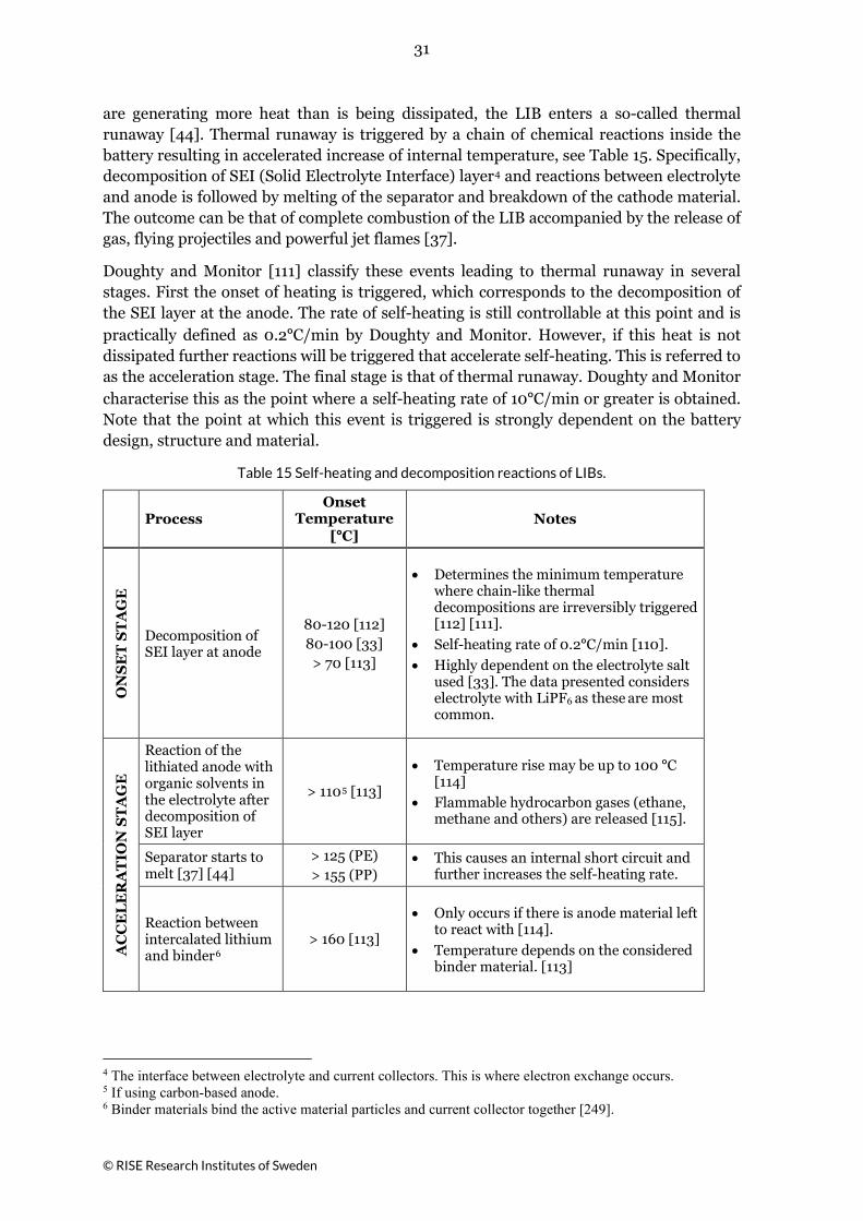
are generating more heat than is being dissipated, the LIB enters a so-called thermal runaway [44]. Thermal runaway is triggered by a chain of chemical reactions inside the battery resulting in accelerated increase of internal temperature, see Table 15. Specifically, decomposition of SEI (Solid Electrolyte Interface) layer4 and reactions between electrolyte and anode is followed by melting of the separator and breakdown of the cathode material. The outcome can be that of complete combustion of the LIB accompanied by the release of gas, flying projectiles and powerful jet flames [37].
Doughty and Monitor [111] classify these events leading to thermal runaway in several stages. First the onset of heating is triggered, which corresponds to the decomposition of the SEI layer at the anode. The rate of self-heating is still controllable at this point and is practically defined as 0.2ºC/min by Doughty and Monitor. However, if this heat is not dissipated further reactions will be triggered that accelerate self-heating. This is referred to as the acceleration stage. The final stage is that of thermal runaway. Doughty and Monitor characterise this as the point where a self-heating rate of 10ºC/min or greater is obtained. Note that the point at which this event is triggered is strongly dependent on the battery design, structure and material.
Table 15 Self-heating and decomposition reactions of LIBs.
Process Onset
Temperature [ºC]
Notes
ON
SE
T S
TA
GE
Decomposition of SEI layer at anode
80-120 [112] 80-100 [33] > 70 [113]
• Determines the minimum temperature where chain-like thermal decompositions are irreversibly triggered [112] [111].
• Self-heating rate of 0.2ºC/min [110]. • Highly dependent on the electrolyte salt
used [33]. The data presented considers electrolyte with LiPF6 as these are most common.
AC
CE
LE
RA
TIO
N S
TA
GE
Reaction of the lithiated anode with organic solvents in the electrolyte after decomposition of SEI layer
> 1105 [113]
• Temperature rise may be up to 100 ºC [114]
• Flammable hydrocarbon gases (ethane, methane and others) are released [115].
Separator starts to melt [37] [44]
> 125 (PE) > 155 (PP)
• This causes an internal short circuit and further increases the self-heating rate.
Reaction between intercalated lithium and binder6
> 160 [113]
• Only occurs if there is anode material left to react with [114].
• Temperature depends on the considered binder material. [113]
4 The interface between electrolyte and current collectors. This is where electron exchange occurs. 5 If using carbon-based anode. 6 Binder materials bind the active material particles and current collector together [249].

32
© RISE Research Institutes of Sweden
Process Onset
Temperature [ºC]
Notes R
UN
WA
Y S
TA
GE
Decomposition of the cathode material.
LFP > 140 [26], 218 [116],
212, 287 [117],
• Usually the main source of heat generation and cause of thermal runaway [112].
• The heat of reaction varies greatly. Xiang et al. recorded a range of 35 to 458 J/g for different cathode materials between 50-225ºC [116].
• Releases oxygen [115]. Higher charge level increases the amount of oxygen released.
LCO > 168 [116]
LMO > 110 [116], > 190 [113]
NMC > 212 [117]
NCA > 183 [117], 139 [118]
Decomposition of electrolyte solvents
> 180 [113] > 202 [116]
• Exothermal reactions. The heat of reaction comprises 258 J/g between 50-225ºC [116].
CO
MB
US
TIO
N
Combustion of solvent [37] [38]
Autoignition > 427
Flashpoint > -3
• The released oxygen facilitates the required conditions for the combustion of flammable organic electrolytes [119].
• Flashpoint ignition requires an ignition source, e.g. a spark or flame from the LIB.
Combustion of solids Varies
• Contribution of plastic oxidation in fire calorimetry tests was estimated equal to that of the electrolyte in terms of heat release [120].
• Highly charged LIBs are a big safety concern due to combustible lithiated anode materials [119].
• Some ignition data of solids may be found in [121].
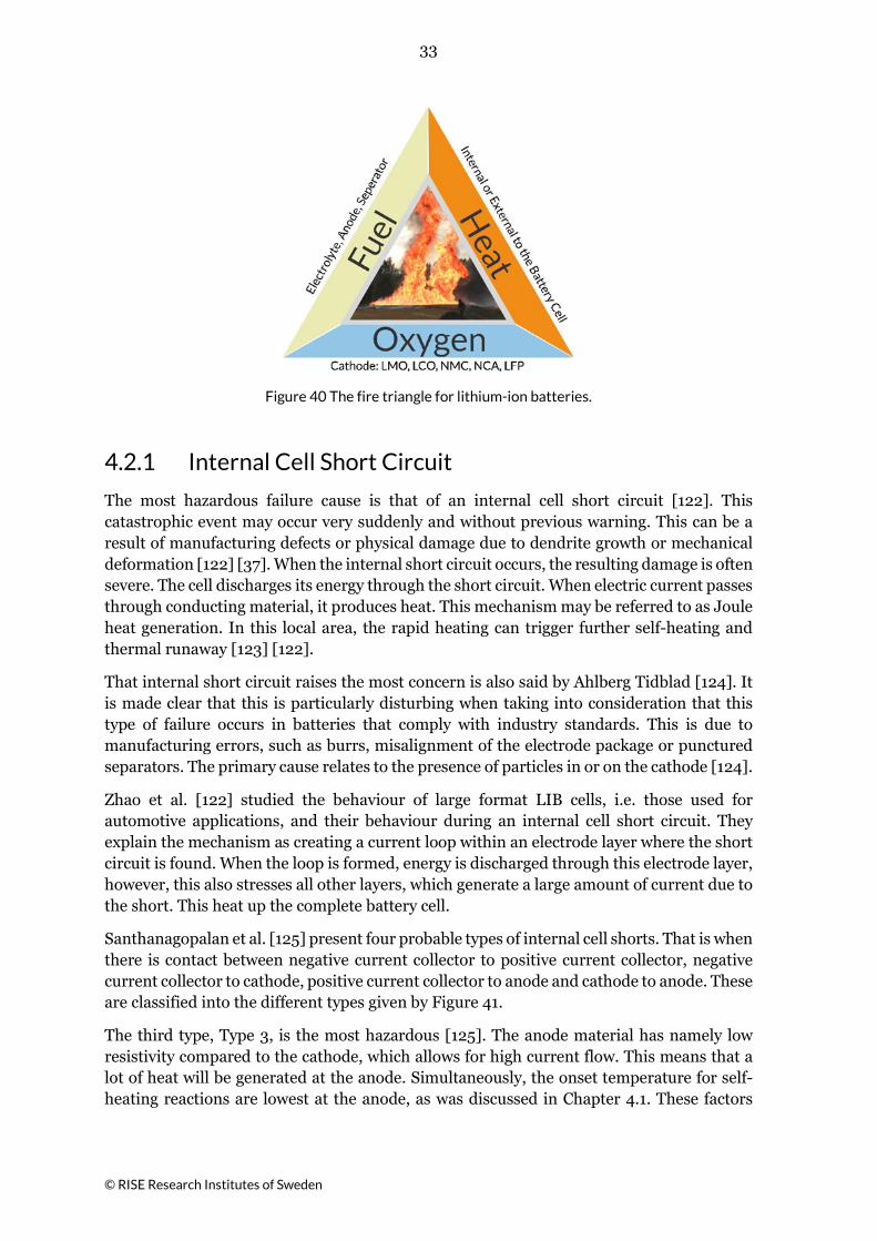
4.2 Battery Failure Causes The catastrophic loss of a cell can result in even more severe consequences such as damage to other system elements, and/or human injury or death. Failure of a cell may be the result of poor cell design or manufacturing flaws, external abuse (thermal, mechanical, electrical), poor battery assembly design or manufacture, poor battery electronics design or manufacture, or poor support equipment (i.e. battery charging/discharging equipment) design or manufacture. The primary battery risks are generally a result of external or internal short circuits, high or low temperatures, overcharge or over-discharge. These mechanisms can result in exothermic reactions within the battery. When temperatures become sufficiently high, or there is an ignition source present that ignites the flammable gases released by the battery, the fire triangle seen in Figure 40. is completed.
33
© RISE Research Institutes of Sweden
Figure 40 The fire triangle for lithium-ion batteries.
4.2.1 Internal Cell Short Circuit
The most hazardous failure cause is that of an internal cell short circuit [122]. This catastrophic event may occur very suddenly and without previous warning. This can be a result of manufacturing defects or physical damage due to dendrite growth or mechanical deformation [122] [37]. When the internal short circuit occurs, the resulting damage is often severe. The cell discharges its energy through the short circuit. When electric current passes through conducting material, it produces heat. This mechanism may be referred to as Joule heat generation. In this local area, the rapid heating can trigger further self-heating and thermal runaway [123] [122].
That internal short circuit raises the most concern is also said by Ahlberg Tidblad [124]. It is made clear that this is particularly disturbing when taking into consideration that this type of failure occurs in batteries that comply with industry standards. This is due to manufacturing errors, such as burrs, misalignment of the electrode package or punctured separators. The primary cause relates to the presence of particles in or on the cathode [124].
Zhao et al. [122] studied the behaviour of large format LIB cells, i.e. those used for automotive applications, and their behaviour during an internal cell short circuit. They explain the mechanism as creating a current loop within an electrode layer where the short circuit is found. When the loop is formed, energy is discharged through this electrode layer, however, this also stresses all other layers, which generate a large amount of current due to the short. This heat up the complete battery cell.
Santhanagopalan et al. [125] present four probable types of internal cell shorts. That is when there is contact between negative current collector to positive current collector, negative current collector to cathode, positive current collector to anode and cathode to anode. These are classified into the different types given by Figure 41.
The third type, Type 3, is the most hazardous [125]. The anode material has namely low resistivity compared to the cathode, which allows for high current flow. This means that a lot of heat will be generated at the anode. Simultaneously, the onset temperature for self-heating reactions are lowest at the anode, as was discussed in Chapter 4.1. These factors

34
© RISE Research Institutes of Sweden
combined are thus most likely to trigger self-heating mechanisms which can lead to thermal runaway.
The remaining short circuit types pose less of a threat according to Santhanagopalan et al [125]. Type 1 does result in a large amount of heat being generated, increasing the external cell temperature up to 100ºC. However, the current collector materials are good conductors of heat, meaning that the generated heat can be dissipated fast enough to prevent further reactions. Type 2 has the lowest amount of localised heating of all types. This is not enough to trigger any self-heating mechanisms. Finally, Type 4, is the most likely internal short circuit type to occur in a battery’s life. However, the resulting current flow is low and is thus not considered a major threat. The result will namely be restricted to a small temperature rise above ambient temperature. It is important to keep the duration of these internal short circuit events in mind. For example, even Types 1, 2 or 4 may trigger a thermal runaway if they are sustained over a long period [125].
Figure 41 There are four different types of internal short circuit paths possible. Not all of them are equally hazardous [125].
4.2.2 Mechanical Deformation and Impact
Mechanical deformation may also initiate an internal short circuit and potentially result in fire, see Figure 42. Severe deformation may be a result of certain crash or ground impact conditions. Severe deformations of the battery pack must be avoided. The high voltage system may be damaged, causing short circuits and arcing and it may also result in the leakage of flammable and conductive liquids. According to Trattnig and Leitgeb [46] the worst-case scenario in a car crash would be the combination of venting gases or leaking fluids with ignition sources such as electrical arcs or hot surfaces. This could lead to a rapid scenario that must be delayed for the, potentially trapped, passengers to escape the vehicle safely.
35
© RISE Research Institutes of Sweden
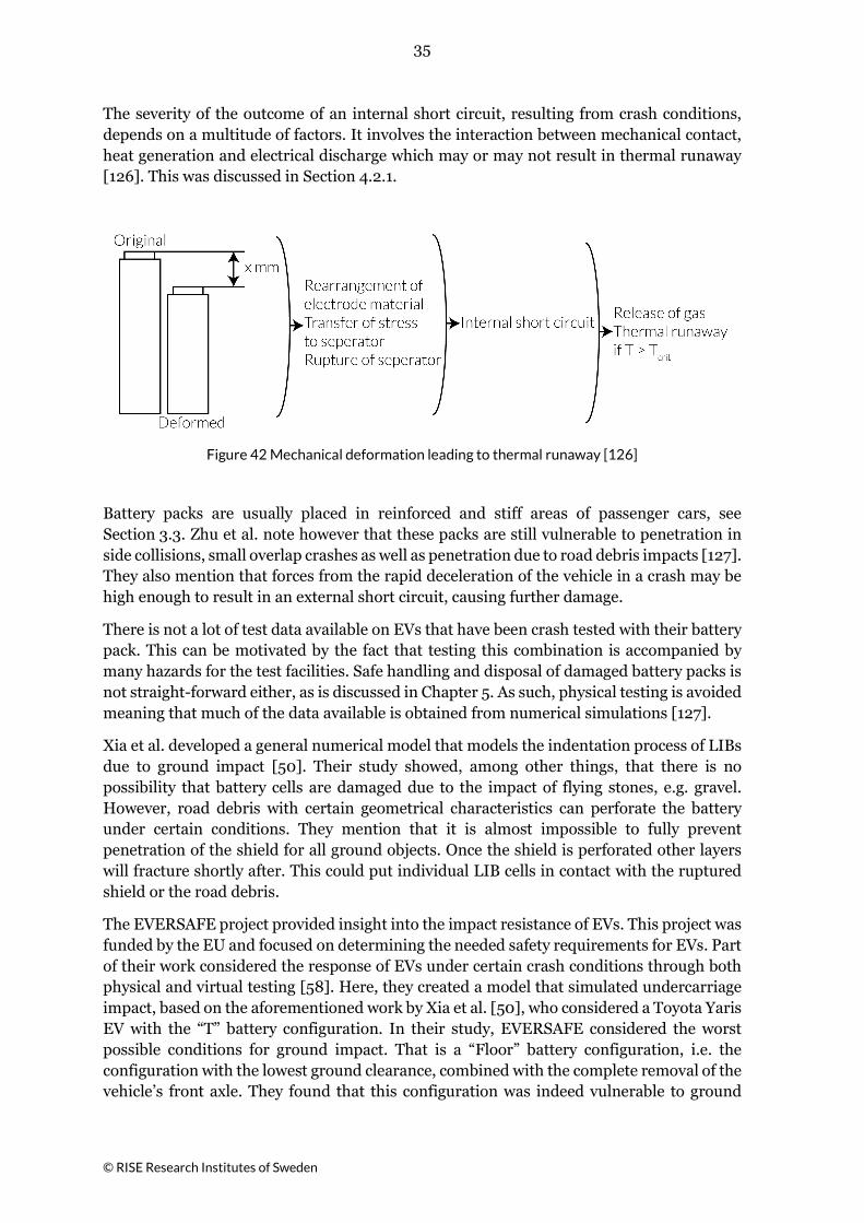
The severity of the outcome of an internal short circuit, resulting from crash conditions, depends on a multitude of factors. It involves the interaction between mechanical contact, heat generation and electrical discharge which may or may not result in thermal runaway [126]. This was discussed in Section 4.2.1.
Figure 42 Mechanical deformation leading to thermal runaway [126]
Battery packs are usually placed in reinforced and stiff areas of passenger cars, see Section 3.3. Zhu et al. note however that these packs are still vulnerable to penetration in side collisions, small overlap crashes as well as penetration due to road debris impacts [127]. They also mention that forces from the rapid deceleration of the vehicle in a crash may be high enough to result in an external short circuit, causing further damage.
There is not a lot of test data available on EVs that have been crash tested with their battery pack. This can be motivated by the fact that testing this combination is accompanied by many hazards for the test facilities. Safe handling and disposal of damaged battery packs is not straight-forward either, as is discussed in Chapter 5. As such, physical testing is avoided meaning that much of the data available is obtained from numerical simulations [127].
Xia et al. developed a general numerical model that models the indentation process of LIBs due to ground impact [50]. Their study showed, among other things, that there is no possibility that battery cells are damaged due to the impact of flying stones, e.g. gravel. However, road debris with certain geometrical characteristics can perforate the battery under certain conditions. They mention that it is almost impossible to fully prevent penetration of the shield for all ground objects. Once the shield is perforated other layers will fracture shortly after. This could put individual LIB cells in contact with the ruptured shield or the road debris.
The EVERSAFE project provided insight into the impact resistance of EVs. This project was funded by the EU and focused on determining the needed safety requirements for EVs. Part of their work considered the response of EVs under certain crash conditions through both physical and virtual testing [58]. Here, they created a model that simulated undercarriage impact, based on the aforementioned work by Xia et al. [50], who considered a Toyota Yaris EV with the “T” battery configuration. In their study, EVERSAFE considered the worst possible conditions for ground impact. That is a “Floor” battery configuration, i.e. the configuration with the lowest ground clearance, combined with the complete removal of the vehicle’s front axle. They found that this configuration was indeed vulnerable to ground

36
© RISE Research Institutes of Sweden
impact, as significant loads were recorded inside the battery for certain impact sizes, shapes and speeds.
The EVERSAFE project also identified and defined critical impact conditions and high-risk conditions for EVs [58] [128]. Two scenarios were of particular interest with respect to the battery, namely longitudinal and lateral impact. Of the longitudinal scenarios considered by EVERSAFE, rear impact was determined to pose the highest risk due to limited legal requirements which may result in that EVs without a fuel tank do not have to demonstrate their crash safety for this crash scenario, which leads to that these EVs do not demonstrate their ability to protect the battery pack in physical rear impact testing. Lateral scenarios consider impacts to the side of a vehicle. These conditions are most likely to result in deformation or intrusion of the battery pack and its protective structure. Of the different side impact tests, side pole impact [129] was deemed most hazardous for EVs.
Another EU project, named OSTLER, performed the Euro NCAP side pole test [129] on a Toyota Yaris EV as part of their work [130]. At a velocity of 50 km/h they found a significant intrusion of the battery pack of 154 mm. The EVERSAFE project performed a similar test on a first-generation Mitsubishi iMiEV at a speed of 35 km/h [128]. They observed no damage to the battery pack and did not detect battery chemicals or gases.
In addition, Justen and Schöneburg from the Mercedes Car Group presented results from a crash safety assessment of their hybrid- and electric vehicles [48]. Although they found major battery intrusions during crash testing there was no thermal or electric reactions resulting in no fire or explosion. In Chapter 5.1 documented incidents resulting in fire are presented. There are also examples of real incidents with high force collision impact without fire [131].
Note that the cases discussed in this section primarily consider passenger cars, as most available information considers those cases. Studies concerning the crash behaviour of LIBs in heavy vehicles such as busses and heavy trucks could not be identified.
4.2.3 Charge
LIBs are designed to receive and store a certain amount of energy over a specific amount of time. When these limits are exceeded, as a result of charging too quickly or overcharging, the cell performance may degrade, or the cell may even fail.
The charge level of batteries is normally defined in terms of state of charge (SOC). Their operational limits may be defined from 0-100%, which means that a battery at 100% SOC is considered fully charged to its rated capacity. However, full capacity of the battery normally goes beyond its rated capacity, both at upper and lower limits.
Overcharging may be realized when the cell voltage is incorrectly detected by the charging control system, when the charger breaks down or when the wrong charger is used [44]. When overcharging, the anode material can become overly lithiated. As a result, lithium intercalation ceases and lithium metal deposits on the anode. These deposits may grow into metallic fingers commonly referred to as dendrites. As they grow, they can reach the point where they penetrate the separator and cause an internal short circuit [132]. The opposite happens at the cathode. Here overcharging may result in it becoming de-lithiated to the point where the cathode decomposes thermally and generates heat.

37
© RISE Research Institutes of Sweden
Brand et al. considered the onset of self-heating due to overcharge abuse of four battery cells [117]. They found that the cells which considered LFP cathode and C anode material were less resistant to overcharge. When they were fully charged and slightly overcharged, 100 % SOC and 105 % SOC, respectively, self-heating mechanisms were triggered. Other cell types, including NMC and NCA with carbon anodes, were also tested. These were more resistant to overcharge as self-heating occurred at 135 % SOC and 130 % SOC, respectively.
When electric current passes through conducting material, it produces heat so called Joule heat. This means that high current, which can be associated with faster charging rates, increases the heat that is generated inside the battery cell. At a high enough current level there is a risk that the battery cell easily fails [44]. Too high charging voltage can also lead to the destabilisation of the cathode structure which may lower the temperature at which the cathode starts to decompose.
The effect of the overcharge conditions, i.e. charging at high charge rates, was demonstrated by Tobishima and Yamaki [44]. They found that at high charge rates of 2C7 the safety vent and anode cap housing would open simultaneously, with the cell exploding. Overcharge tests were also performed by Larsson et al. in [133] and [134]. In the former study, one out of four LFP cells that were overcharged with 2C resulted in fire. Wang et al. [115] summarised the outcome of several overcharge abuse tests. They mention that in general, abuse can occur when charging at 0.5C and above.
Low temperature charging, e.g. below 0°C, should be avoided to prevent fast initiation and growth of lithium dendrites capable of forming internal short circuits. Recall that during the charging process, lithium-ions move from cathode to the anode. They are then stored in the layered structure of the anode. Charging at low temperatures affects this kinetic process within the LIB cell. As a result, the lithium-ions may form metallic lithium instead of intercalating into the anode. These quickly initiate dendrites [135]. In turn this can cause internal short circuits.
4.2.4 Discharge
When the LIB is discharged, lithium-ions flow from the negative current collector and anode to the positive current collector and cathode. If the level of discharge becomes too great however, the negative current collector, which consists of copper, can dissolve. As a result, small conductive copper particles are released in the electrolyte which increase the risk for an internal short circuit [132]. It can also lead to the evolution of hydrogen and oxygen, cell venting and plating on the cathode.
Overdischarge abuse occurs when discharging battery cells below their minimum voltage. In the unlikely event where four battery cells are in series, and one of them is completely discharged (0 V), this could lead to the empty cell being discharged even further [117]. In this case the polarity of the cell reverses. Brand et al. considered this scenario in their study of over-discharge abuse on C/LFP, C/NMC and C/NCA cells. They discharged the batteries from 100 % SOC at a 1C rate but did not measure significant temperature increases (max. 47.5ºC) or observe damage to the cell casing.
7 This refers to the charge and discharge rate of the battery. A 2C charge rate means that the current for charging is twice as high as the batteries capacity to store electrical charge. 1C is the current needed to fully charge the battery in one hour.

38
© RISE Research Institutes of Sweden
Overdischarge abuse tests on C/NMC pouch cells with a capacity of 25 Ah were performed by Guo et al. [136]. They identified the different stages of failure during overdischarge conditions. At -10% SOC (of full capacity, which means reversed polarity of the cell) the SEI layer on the anode began to decompose, followed by the dissolution of the copper current collector at -12% SOC. Charge levels below -12% resulted in internal short-circuits, where their intensity increased with decreasing charge levels. Guo et al. also mention that this risk is greater when battery cells that are connected in series [136].
Overdischarge can occur when discharging a battery where the charge levels of its individual cells is not in balance. Normally safety systems are in place to prevent this. However, it is still possible that this occurs if these safety systems fail and the battery is misused [132]. In case it has been stored for long periods of time so that self-discharge has an effect, charging may cause problems if individual cells reach too low SOC. However, self-discharge cannot by itself cause overdischarge in the sense of reversed polarity.
4.2.5 External Short Circuit
An external short circuit is another form of electric abuse that may destabilise the battery. This event may occur in case the battery is exposed to, for example, severe mechanical deformation and impact, immersion in water, corrosion and electric shock during maintenance.
The response of stainless-steel prismatic C/LCO cells when exposed to an external short was investigated by Leisner et al. [137]. They observed a very high current peak and an internal cell temperature of 132°C for a C/LCO cell. Note that these cells were not equipped with current limiting or temperature trip safety devices.
External short circuit tests were performed by Davidsson et al. on three different cell types [138]. This was achieved with a contactor that was limited to 10 000 A. Short circuit of a cell with hard-plastic packaging material corresponded to an initial current of 3200 A being registered. The pressure inside the cell then increased significantly and the cell burst into pieces. A pouch cell, with a metal foil enclosure, expanded significantly after an initial current of 1800 A followed by cell rupture. The last battery, with metal casing, was not affected by the short circuit. No activity was observed after the initial current of 200 A was measured. It is unclear whether the considered cells had built-in fuses or safety vents.
Wang et al. summarised the results of external short circuit tests [115]. The test method considered connecting a resistor across the terminals to allow current flow to heat up the considered battery cell. They mention that although there is internal heating, there is also significant heat dissipation of the external circuit. They did not mention whether this was enough to prevent self-heating mechanisms from being triggered.
Larsson et al. performed external short circuit abuse testing on LIB cells [133], [134]. In the former test the cell expanded 20 to 30 seconds after the short circuit had been initiated. Then the measured current dropped while the cells ventilated for 2 minutes. External cell temperatures of up to 100ºC were recorded followed by discharge to 43% SOC. The terminal tabs burnt off during this test for one of the considered battery cells and thus broke the external short circuit.
The external short circuit resistance of independent and series connected 10Ah pouch cells was studied by Kriston et all. [139]. Short circuit was initiated by connecting the battery

39
© RISE Research Institutes of Sweden
terminals using different external resistances. They classified the behaviour that followed into three stages. First high currents are recorded. This is followed by a current drop, increase in cell temperature, vaporisation of electrolyte, pressure build-up and venting of the cells. Finally, as the active material discharges, the current drops. Note that thermal runaway or the release of significant smoke was not observed for the studied cells. The reader is referred to Kriston et al for videos and detailed images of the tests [139].
4.2.6 Exposure to High Temperatures
One of the limiting factors of LIB cell safety is its thermal stability. When exposed to high temperatures internal degradation mechanisms and exothermic reactions may lead to problems. When the external temperature of the battery is higher than the internal temperature, it is heated instead of cooled. Once the battery warms up to certain temperature levels, decomposition mechanisms are triggered causing the battery to generate further heat. As shown previously in Table 15, the true problem then arises when the Runaway Stage is reached.
Resistance to high external temperatures may be assessed by external heating in oven or by an external fire. Larsson et al. considered external heating by oven in [133], [134] and [140]. Here LIB cells were mounted in an oven that was heated to 300°C in a set amount of time. In [140] this method was employed to assess hard prismatic LCO-graphite cells. This study found that all cells underwent thermal runaway at temperatures above 190°C and were releasing smoke and gas. Note that this temperature refers to the last point before the temperature increases tremendously. For roughly half of the studied cases, accumulated gases in the oven ignited and exploded. This occurred approximately 15 seconds after thermal runaway was initiated. Another study by Larsson et al. [133] found that thermal runaway of a cylindrical Samsung 18650 cell was observed at approximately 220°C. This resulted in an immediate fire and an extreme rate of temperature increase. Furthermore, shortly before thermal runaway, the cell discharged burning electrolyte. The same study also considered LFP pouch cells. Here they observed no or very weak signs of thermal runaway.
Instead of placing the battery cells in an oven, they can be exposed to external fire. In a similar fashion to what was discussed before, this may trigger a thermal runaway event. Larsson et al. studied this in [134], [141], [142], [143] by exposing different LIB cells to propane burner.
The complete battery pack may also be exposed to an external fire. This could be the result of fuel leak for example, which accumulates underneath the LIB pack and ignites. Over time this heat may penetrate a battery pack, initiate cell failure, and spread further within the pack. To mitigate this risk EVs must pass fire resistance testing, i.e. UNECE Reg. No. 100 [144]. The amount of time in which the battery pack is exposed to external flames is 2 minutes. This test is similar to the test conducted on gasoline tanks. In the test the size of the fire is determined by the geometry of the battery or tank respectively. When there is no evidence of explosion during these 2 minutes or the following observation period, or the following observation period, where the test object is to reach ambient temperatures or has its temperature decrease for at least 3 hours, this test can be considered passed. Note that the test may be performed on either the full-scale level (EV), or component level (LIB pack). In the case of the former, recorded tests have shown that a very high fire resistance can be achieved. The LIB pack has been found to not contribute to the fire for 25-40 minutes when

40
© RISE Research Institutes of Sweden
integrated in an EV. This resistance drops when the battery is considered separately. Then the time may reduce down to 2-11 minutes [145] [146] [147] [148] [149] [150].
Exposure to high temperatures may also be the result of manufacturing faults such as loose battery cell connectors. Beauregard investigated a PHEV destroyed by fire in 2008 [151]. They found that the likely cause of this event were loose connectors. In combination with a vibrating vehicle, this led to the build-up of heat. In turn the battery cells short circuited which eventually resulted in the vehicle burning down.
Finally, it is important to consider that there can be negative implications to raising the ambient temperature of the LIB. Although this may not directly trigger negative reactions it does reduce the safety margin. When close to the edge of this margin, internal short circuit reactions that would not otherwise trigger further-self heating reactions may push a battery cell over the edge [125].
4.3 Hazards and Risk Factors When a battery does fail this may have several different outcomes, e.g. venting, fire or even explosion. These different hazards have been classified by the European Council for Automotive Research and Development (EUCAR), see Table 16. Here an explosion is the most severe event. When heating LIBs their internal pressure builds up and eventually the cell cracks and/or ventilates or explodes. It is cell explosion that is referred to in Table 16. In addition, if the released gas can accumulate to create an explosive environment which is ignited it leads to an explosion. This type of explosion is usually not addressed by battery testing, except in some more recently developed tests.
In 2015, Hendricks et al. developed a comprehensive method of analysing the failure modes, mechanisms, and effects (FMMEA) of LIBs [132]. The FMMEA produces a risk prioritization number that combines the likelihood of occurrence, the severity, and the detectability of the failure for a specific battery system. Their article included a resulting table which summaries an FMMEA of LIBs focused on internal failure modes within a battery cell.
The factors that affect the severity of these hazards are varying and complex. Among other things, they can be linked to the battery chemistry, its charge level and the failure cause. This section focusses on battery chemistry and charge level. In addition, the risk for failures to propagate from one cell to the next is discussed.

41
© RISE Research Institutes of Sweden
Table 16 European Council for Automotive Research and Development (EUCAR) hazard levels and descriptions [152]
Hazard Level Description Classification Criteria and Effect
0 No effect No effect. No loss of functionality.
1 Passive
protection activated
No defect; no leakage; no venting, fire, or flame; no rupture; no explosion; no exothermic reaction or thermal runaway. Cell irreversibly damaged. Repair of protection
device needed.
2 Defect/damage No leakage; no venting, fire, or flame; no rupture; no
explosion; no exothermic reaction or thermal runaway. Cell irreversibly damaged. Repair needed.
3 Leakage,
∆𝑚𝑚𝑚𝑚𝑚𝑚𝑚𝑚 < 50%
No venting, fire, or flame8; no rupture; no explosion. Weight loss <50% of electrolyte weight (electrolyte =
solvent + salt)
4 Venting,
∆𝑚𝑚𝑚𝑚𝑚𝑚𝑚𝑚 ≥ 50% No fire or flame8; no rupture; no explosion. Weight loss ≥
50% of electrolyte weight (electrolyte = solvent + salt).
5 Fire or flame No rupture; no explosion (i.e., no flying parts).
6 Rupture No explosion, but flying parts of the active mass.
7 Explosion Explosion (i.e., disintegration of the cell).
4.3.1 Chemistry
The thermal runaway and the heat and fire development in batteries varies with battery chemistry. A study performed by Maleki et al. [153] concluded that exothermic reactions between electrolyte and cathode material at elevated temperatures are the main contributors to thermal runaway. Doughty and Pesaran [111] state that the order of thermal stability for cathode materials follows LFP>LMO>NCM>NCA>LCO, in decreasing order. It is important to note that thermal stability refers to the amount of heat that is generated per unit time when exothermic reactions have been triggered. It does not reflect on the temperature at which they are triggered.
Abuse testing by Larsson et al. [37] has shown that thermal runaway is initiated after the temperature of the battery cell reaches 150-200ºC. They also showed that LIBs with an LFP cathode has a less severe thermal runaway event than a LIB with LCO cathode [133].
Xiang et al. [116] investigated the thermal stability of LiPF6-based electrolyte9, both independently and while being in contact with various cathode materials. They found that the electrolyte yields strong exothermic reactions below 225ºC. Following this, they looked at the LiPF6-based electrolyte in combination with several cathode materials. This showed
8 “The presence of flame requires the presence of an ignition source in combination with fuel and oxidizer in concentrations that will support combustion. A fire or flame will not be observed if any of these elements are absent. For this reason, we recommend that a spark source be use during tests that are likely to result in venting of cell(s). We believe that “credible abuse environments” would likely include a spark source. Thus, if a spark source were added to the test configuration and the gas or liquid expelled from the cell was flammable, the test article would quickly progress from level 3 or level 4 to level 5” [152]. 9 Found in the vast majority of commercial LIBs [37].

42
© RISE Research Institutes of Sweden
that LCO can release oxygen at elevated temperatures and further induce the combustion reaction of LiPF6-based electrolyte.
Xiang et al. [116] also investigated cells with LFP cathodes. They found that this cathode material can inhibit the decomposition of electrolyte and yield a less severe thermal runaway event. Specifically, its reaction heat measured 35 J/g between 20-225ºC. In comparison, the electrolyte by itself or together with either LCO or LMO cathodes resulted in 258 J/g, 358 J/g and 308 J/g, respectively.
Xiang et al. [116] also found that the onset temperature for decomposition reactions of cathode materials was highest for LFP, i.e. 218ºC. Other tested cathodes such as LCO and LMO yielded onset temperature around 168 ºC and 110ºC, respectively. At 202 ºC, polymeric products in the LiPF6-based electrolyte started to decompose. Note that LMO, which is considered safer than LCO [111], was found to have a lower onset temperature. This is because safety is often connected to thermal stability and not by onset temperature. Xing el. al. [115] argues that the reaction heat released below 225 ºC is the key indicator for thermal stability, which was found to be lower for LMO than LCO.
Brand et al. [117] recorded the onset temperatures for different LIB cells using accelerated arc calorimetry. They found that self-heating with temperature rates higher than 5ºC/min. occurred at temperatures of 212 ºC and 287 ºC for the LFP cells. The onset temperatures for the NMC and NCA cells was found to correspond to 212 and 183 ºC, respectively.
From a fire and heat generation perspective, LFP is the preferred option. It may however not be as favourable when considering the release of toxic gases or the risk for explosion. Larsson argues that this may be the negative side-effect of the suppression effect that LFP has [37]. The mixture of gases emitted from LIBs namely tends to be more toxic when it is not burning. In addition, the gases can accumulate and experience a delayed ignition resulting in a gas-explosion if it occurs in a confined place such as a room, building, parking garage etc [154].
4.3.2 State of Charge and Cell Capacity
The capacity and state of charge (SOC) affects, among other things, the behaviour of a LIB leading up to and during thermal runaway. Battery cells with high capacity, such as those used for automotive applications, generate more heat when in use. This is due to the higher current flow within the cell. This makes them more vulnerable as self-heating reactions will be triggered faster, increasing the likelihood of thermal runaway [125]. At greater charge levels, the extent of lithiation on the anode is much greater. This material is highly reactive and has been shown to increase the likelihood of thermal runaway [125] [118].
Larsson et al. performed abuse tests on batteries with varying levels of charge in [134] and [141] by exposing them to external fire. Here they showed that a higher charge level corresponds to a more rapid total energy release and a higher peak energy release rate. A lower charge level yielded a lower energy release rate spread out over a longer time. However, the charge level of the batteries did not have a significant effect on the total amount of energy released.
The release of toxic gasses is also affected by the SOC level of a LIB [141]. Larsson et al. showed that lower SOC yielded higher amounts of hydrogen fluoride (HF) to be released. Similar results were found by Ribière et al. in [120]. They conclude that the measured
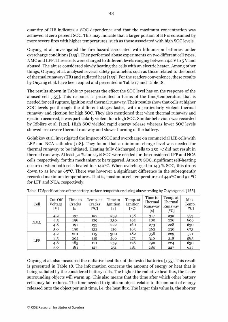
43
© RISE Research Institutes of Sweden
quantity of HF indicates a SOC dependence and that the maximum concentration was achieved at zero percent SOC. This may indicate that a larger portion of HF is consumed by more severe fires with higher temperatures, such as those associated with high SOC levels.
Ouyang et al. investigated the fire hazard associated with lithium-ion batteries under overcharge conditions [155]. They performed abuse experiments on two different cell types, NMC and LFP. These cells were charged to different levels ranging between 4.2 V to 5 V and abused. The abuse considered slowly heating the cells with an electric heater. Among other things, Ouyang et al. analysed several safety parameters such as those related to the onset of thermal runaway (TR) and radiated heat [155]. For the readers convenience, these results by Ouyang et al. have been copied and presented in Table 17 and Table 18.
The results shown in Table 17 presents the effect the SOC level has on the response of the abused cell [155]. This response is presented in terms of the time/temperature that is needed for cell rupture, ignition and thermal runaway. Their results show that cells at higher SOC levels go through the different stages faster, with a particularly violent thermal runaway and ejection for high SOC. They also mentioned that when thermal runaway and ejection occurred, it was particularly violent for a high SOC. Similar behaviour was recorded by Ribière et al. [120]. High SOC yielded rapid energy release whereas lower SOC levels showed less severe thermal runaway and slower burning of the battery.
Golubkov et al. investigated the impact of SOC and overcharge on commercial LIB cells with LFP and NCA cathodes [118]. They found that a minimum charge level was needed for thermal runaway to be initiated. Heating fully discharged cells to 250 ºC did not result in thermal runaway. At least 50 % and 25 % SOC were needed for the considered LFP and NCA cells, respectively, for this mechanism to be triggered. At 100 % SOC, significant self-heating occurred when both cells heated to ~140ºC. When overcharged to 143 % SOC, this drops down to as low as 65ºC. There was however a significant difference in the subsequently recorded maximum temperatures. That is, maximum cell temperatures of 440ºC and 911ºC for LFP and NCA, respectively.
Table 17 Specifications of the battery surface temperature during abuse testing by Ouyang et al. [155].
Cell Cut-Off Voltage
[V]
Time to Cracks
[s]
Temp. at Cracks
[ºC]
Time to Ignition
[s]
Temp. at Ignition
[ºC]
Time to Thermal Runaway
[s]
Temp. at Thermal Runaway
[ºC]
Max. Temp. [ºC]
NMC
4.2 197 127 239 158 317 232 553 4.5 196 129 230 162 280 226 606 4.8 191 133 222 160 273 228 630 5.0 190 132 219 163 262 230 673
LFP
4.2 201 115 300 182 358 229 571 4.5 202 115 266 175 310 218 585 4.8 185 121 259 178 290 224 630 5.0 181 127 251 181 280 227 647
Ouyang et al. also measured the radiative heat flux of the tested batteries [155]. This result is presented in Table 18. The information concerns the amount of energy or heat that is being radiated by the considered battery cells. The higher the radiative heat flux, the faster surrounding objects will warm up. This also means that the time after which other battery cells may fail reduces. The time needed to ignite an object relates to the amount of energy released onto the object per unit time, i.e. the heat flux. The larger this value is, the shorter
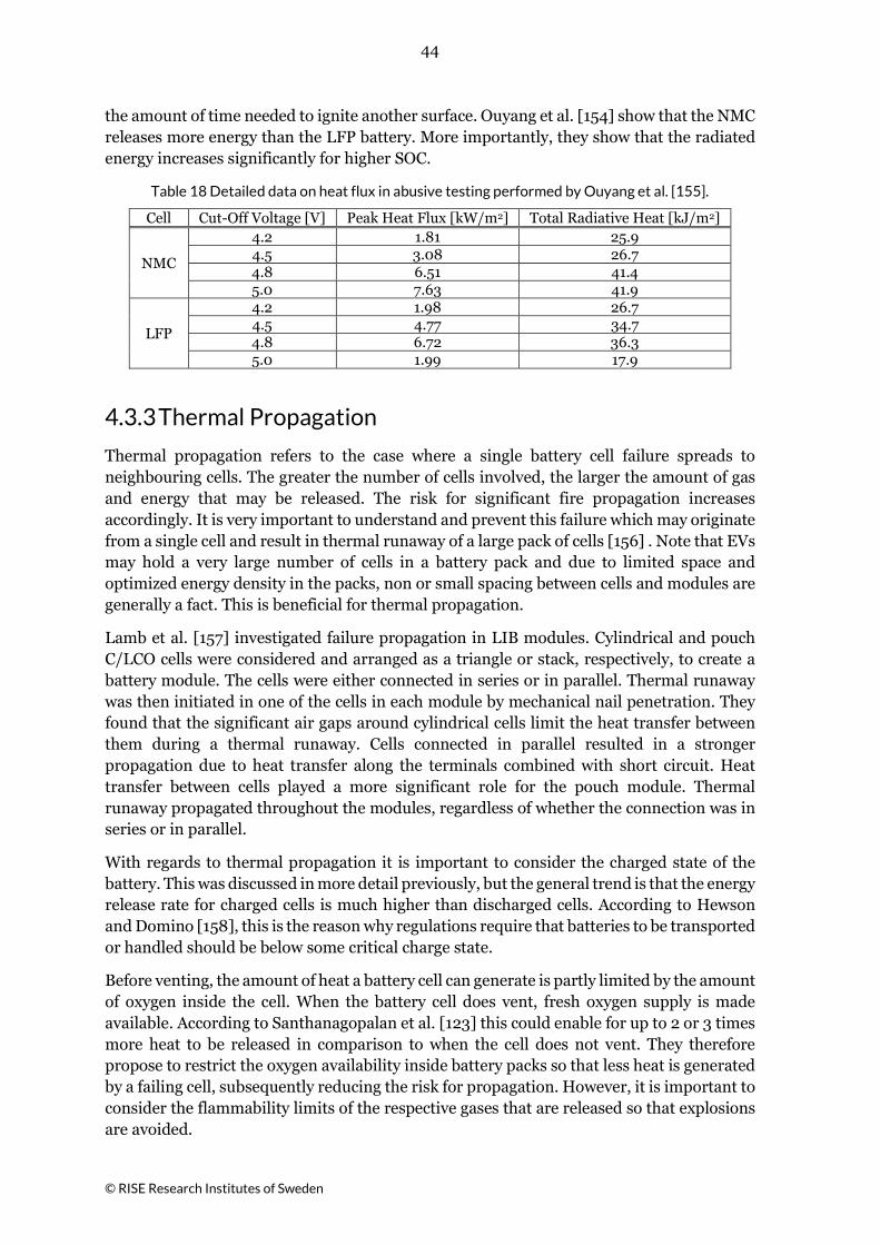
44
© RISE Research Institutes of Sweden
the amount of time needed to ignite another surface. Ouyang et al. [154] show that the NMC releases more energy than the LFP battery. More importantly, they show that the radiated energy increases significantly for higher SOC.
Table 18 Detailed data on heat flux in abusive testing performed by Ouyang et al. [155].
Cell Cut-Off Voltage [V] Peak Heat Flux [kW/m2] Total Radiative Heat [kJ/m2]
NMC
4.2 1.81 25.9 4.5 3.08 26.7 4.8 6.51 41.4 5.0 7.63 41.9
LFP
4.2 1.98 26.7 4.5 4.77 34.7 4.8 6.72 36.3 5.0 1.99 17.9
4.3.3 Thermal Propagation
Thermal propagation refers to the case where a single battery cell failure spreads to neighbouring cells. The greater the number of cells involved, the larger the amount of gas and energy that may be released. The risk for significant fire propagation increases accordingly. It is very important to understand and prevent this failure which may originate from a single cell and result in thermal runaway of a large pack of cells [156] . Note that EVs may hold a very large number of cells in a battery pack and due to limited space and optimized energy density in the packs, non or small spacing between cells and modules are generally a fact. This is beneficial for thermal propagation.
Lamb et al. [157] investigated failure propagation in LIB modules. Cylindrical and pouch C/LCO cells were considered and arranged as a triangle or stack, respectively, to create a battery module. The cells were either connected in series or in parallel. Thermal runaway was then initiated in one of the cells in each module by mechanical nail penetration. They found that the significant air gaps around cylindrical cells limit the heat transfer between them during a thermal runaway. Cells connected in parallel resulted in a stronger propagation due to heat transfer along the terminals combined with short circuit. Heat transfer between cells played a more significant role for the pouch module. Thermal runaway propagated throughout the modules, regardless of whether the connection was in series or in parallel.
With regards to thermal propagation it is important to consider the charged state of the battery. This was discussed in more detail previously, but the general trend is that the energy release rate for charged cells is much higher than discharged cells. According to Hewson and Domino [158], this is the reason why regulations require that batteries to be transported or handled should be below some critical charge state.
Before venting, the amount of heat a battery cell can generate is partly limited by the amount of oxygen inside the cell. When the battery cell does vent, fresh oxygen supply is made available. According to Santhanagopalan et al. [123] this could enable for up to 2 or 3 times more heat to be released in comparison to when the cell does not vent. They therefore propose to restrict the oxygen availability inside battery packs so that less heat is generated by a failing cell, subsequently reducing the risk for propagation. However, it is important to consider the flammability limits of the respective gases that are released so that explosions are avoided.
45
© RISE Research Institutes of Sweden
4.4 Challenges for Responders In 2013 Long et al. conducted full scale fire tests on two battery types using a mock-up vehicle shell used for firefighter training purposes [147]. One of the goals of these tests was to determine whether there are special requirements for firefighting operations involving electric vehicles compared to conventional ICE vehicles. The batteries were placed in relatively easily accessible locations in the vehicle: in the rear cargo storage compartment, either in plain view or under a mock “floorboard”. The firefighters observed that the biggest challenge was to supply water to the source of the fire. They could cool the outside of the battery pack, but they could not reach the burning cells unless there was a way to inject the water inside the pack. The fires reignited multiple times in 5 of the 6 tests.
With regard to firefighting operations, researchers have also found that normally there is no danger to firefighters for electric shock due to using water as an extinguishing agent [147] [159]. Two series of fire tests have included suppression of LIB fires with water mists [37] [141]. In both cases the total HF emissions were similar whether water mist was used or not, but HF production increased significantly while water mist was being applied to the fire. Exposure to HF could thus be a hazard for the fire service if water mist is used as the suppression agent or possible other water-based agents, however, very little research has been conducted on this. Additional information about the toxicity of the gases emitted by LIB is found in section 4.4.2 below.
Egelhaaf [146] found that a very large amount of smoke was emitted after the batteries were extinguished and recommended that a larger than normal area should be blocked off compared to an ICE vehicle fire.
For electrical vehicles there is not only the threat of a fire immediately after a crash, but also the risk of a delayed event. This could occur during post-crash handling, including towing and workshop activities. In addition, there is a risk of reignition significant amounts of time after first extinguishment. These risks connected to handling of damaged EVs are elaborated in greater details in section 5.2.
4.4.1 Identifying Electric Vehicles
One of the biggest challenges for responders is to identify the type of vehicle they are dealing with [160]. Grant [159] states that it can be hard to distinguish EVs from ICE vehicles due to their similar exterior characteristics. It is very important to understand what type of vehicle is being dealt with in order to make an appropriate assessment of its associated hazards.
BEVs are arguably the easiest to distinguish from conventional vehicles as they do not have an exhaust system, and thus no tailpipe. However, this might still be difficult to determine in a crash situation. High-voltage components are identifiable from their orange colour and the presence of warning stickers.
Some EVs can be recognised by badges or stickers on their rear or sides. Apart from looking for stickers or badges on the vehicle, Moore proposes to also look for small doors on the side, front or rear of the vehicle to determine whether the considered vehicle is a plug-in EV (PHEV & BEV) [161]. The small doors Moore refers to may conceal the fuel-filler neck or charging port. Two doors indicate the vehicle is a PHEV, one for charging and one for

46
© RISE Research Institutes of Sweden
fuelling. If there is only one door, this will have to be opened to conclude whether it is for fuelling or charging. It is important to take into consideration that this strategy cannot be used to assess whether a vehicle may have a LIB on-board. HEVs are not designed for plug-in charging but may still house e.g. a 48 V LIB [17].
Although immediate recognition may not be possible based on the exterior of the vehicle alone, an understanding of the general construction of EVs may be helpful. The information shown in Chapters 2 and 3 provides some basic information on this matter. Among other things, it was found here that battery packs, and thus also the high-voltage components, are normally placed underneath the floor and away from crumple zones. This is particularly true for passenger cars. For busses the batteries may be spread over several different locations. There are not many heavy electric trucks on the market yet, but a likely location for the high-voltage system is between their front and rear wheel axles.
There are applications available that can aid in this matter. One of them is the Crash Recovery System (CRS) developed by Moditech Rescue Solutions BV [162]. Programmes such as theirs can be helpful in handling EVs as it provides information on, among other things, the location of battery packs and high-voltage systems.
4.4.2 Toxicity of Vented Gases and Fire Water Run-Off
The toxicity of emissions from LIBs is an area of concern for the safety of passengers in EVs, firefighters and other emergency response personnel, and for the environment. This hazard is heightened when the vehicle emits gases in a confined space such as a car park or tunnel. The LIB cells can produce a large amount of toxic gas when they experience thermal runaway and can also vent gases without undergoing thermal runaway [154]. The composition of these gases depends on the cell chemistry and the state of charge, temperature, pressure and surrounding atmospheric conditions [163]. Efforts to suppress LIB fires can result in a relatively large amount of contaminated water or other foam/liquid run-off material that should be collected and disposed of in a responsible manner.
Carbon monoxide (CO) gas emissions are normal when carbon-based materials burn. It is not currently known whether CO poses more of a threat in an EV fire than in an ICE fire. Possible differences may be related to interactions between CO and the gases emitted from the battery, especially in the confined space of a vehicle [120]. The mixture of gases emitted from LIBs tends to be more toxic when it is not burning. The gases can accumulate and experience a delayed ignition resulting in a gas explosion if it occurs in a confined space [154].
The greater concern is hydrogen fluoride (HF), because it is severely irritating to humans at low concentrations and because significant quantities of HF have been found in reported fire tests [37] [120] [150] [164]. The HF can be gaseous, or it can be dissolved in fire water run-off. Fluorine comes from the electrolyte and sometimes the binder or separator in the LIB cells but is also found in flame retarded materials such as plastics in the vehicle and the air conditioning media. Thus, both EVs and ICEVs produce HF when they burn, although fire tests show that an EV produces more HF than an ICEV, and the timing of the peak release(s) may be different due to burning of the battery and air conditioning system [150]. DNV GL states that the average emissions of gases per kg from a burning battery are lower than that from burning plastic [165]; however, they don’t specify the toxicity of the emissions or the type of plastic.

47
© RISE Research Institutes of Sweden
HF is a toxic, corrosive, light weight gas that can penetrate some types of protective gear [164]. A new study however indicate that protective gears protect much better against HF penetration than previously thought [166]. Firefighters may be hesitant to approach a burning EV without wearing a chemical suit. Lecocq found that the amount of HF measured in the smoke plume during their fire tests was above the safe threshold for both EV and ICE vehicles, but the HF concentration near the firefighter closest to the burning vehicle was below the same threshold [150]. However, smoke concentration experienced by firefighters is highly scenario dependent and for a confined space it may be much higher. Fire tests have also found that applying water mist to LIB fires increases the production of HF significantly during the application process, although the total amount of HF produced during the fires did not change [37] [141].
Dissolved species in fire water run-off were analysed in Egelhaaf’s work, in which elevated levels of fluoride and chloride were measured [167]. According to German regulations, these concentrations are too high to be released directly into the environment, meaning that the run-off water must be sent to a wastewater treatment plant. For these tests, each extinguished battery was left overnight stored in a container of saltwater. The storage water was also analysed and found to have elevated levels of fluoride and chloride. When F-500® and Firesorb® were used to extinguish the battery fire, the fire was extinguished so quickly that there was not enough water to have a viable sample for analysis.
4.4.3 Fibre Composite Materials
One issue modern EVs are dealing with is the relatively low energy density of LIBs compared to conventional fuels. As a result, a large portion of the vehicles total weight is the battery pack in order to achieve the driving ranges demanded by consumers. One way of achieving longer range without having to add more batteries is through the consideration of lighter structural materials. This has led to the introduction of more light-weight composite materials in modern vehicles. Carbon-fibre reinforced polymers (CFRPs) are particularly suitable for this, as they allow for the design of very stiff and lightweight structures. It is therefore used to protect the occupant space of the BMW i3 for example [168].
There are however some risks associated to these materials when they become damaged or exposed to fire. Hertzberg provides several examples [169]. Firstly, when exposed to fire, CFRPs may release inhalable fibres. A small fraction of these airborne fibres may cause irritation/inflammation of lung tissues, fibrosis and cancer. In addition, violent destruction of this material, e.g. in a crash scenario, can also result in the release of fibres. Lastly, direct contact with the damaged CRFP can result in small fibres penetrating through skin, causing irritation or inflammation.
It is important to consider these hazards such that appropriate protective equipment can be worn, especially when handling damaged EVs. Moore [170] recommends significant respiratory protection throughout the entire time any carbon-fibres could be present or airborne. Protection against skin penetration should however also be considered when there is the risk for direct contact with damaged CFRPs.

48
© RISE Research Institutes of Sweden
5 Collisions and Fires The probability of post-crash fires increases with collision energy regardless if the vehicle has a LIB or not. In addition, trends indicate that the survivable collision energy is increasing with newer vehicles which means that the occupants of a new vehicle may survive a high energy collision but will sustain severe injuries or death due to a post-crash fire [171]. For electrical vehicles there are not only the threat of a fire immediately after a crash, but also the risk of a delayed battery event and fire that can affect towing and workshop activities. In the sections below, an overview of documented fire incidents including EVs is presented as well as an examination of available guidelines and risks connected to handling of damaged EVs.
5.1 Documented Incidents The introduction of a new concept, such as electrical vehicles, is always carefully examined, and many incidents involving EVs have attracted considerable media attention. In Table 19 some of these incidents are summarized. EV incidents have often been followed by discussions of their long-term viability, no matter the cause of the incident. Table 19 is followed by a separate section which discusses trends and available statistics on fires in electrical vehicles.
Table 19 Summary of some EV fires that have brought attention.
Year Location Vehicle Incident Cause Comments
2010 [172]
On Ferry “Pearl of Scandinavia”
Rebuilt Nissan Qashqai
Fire during charging
After the incident, the shipowner temporary forbid charging
2011 [173]
Hangzhou, China Zotye M300 EV Fire while
driving
All electric taxis (30) in the city were temporary pulled off the streets due to the incident
2011 [174]
Wisconsin, USA Chevrolet Volt Fire 3 weeks after crash test
Leaking coolant in battery
The delayed fire event was also reproduced
2012 [47]
Michigan, USA GM testing facility
Battery explosion during testing
Old operating cycle not compatible with new battery prototype
2012 [47]
Shenzhen, China BYD e6
Hit from behind and collision with tree
High collision impact, the tree penetrated 1 m
3 fatalities (probably due to incident, not the fire)
2012 [47]
Sweden Rebuilt Fiat 500
Fire during charging (after 25 hours)
Fire started in engine compartment, probably heater

49
© RISE Research Institutes of Sweden
Year Location Vehicle Incident Cause Comments
2012 [175]
Texas/ California, USA 2 Fisker Karma Fires in parked
vehicles
Second fire: the damage was confined away from the battery
2 fires among 1000 Fisker Karma hybrid electric sedans
2012 [176]
New Jersey, USA
3 Toyota Prius & 16 Fisker Karma
Fire in vehicles immersed in sea water due to hurricane Sandy
Saltwater
More than 2000 Toyotas (hybrid) not having a fire
2013 [177]
Paris, France 2 Bolloré Bluecar
Fire in parked vehicle and spread to second vehicle
Maybe vandalism, but not for sure
2013 [178]
USA, Mexico 3 Tesla Model S 3 different fires within 6 weeks
Hitting road debris and concrete wall (and tree)
After the incidents, Tesla reinforced the construction
2013 [179]
Japan Mitsubishi Outlander PHEV
A few battery overheating incidents
Production was shut down for 5 months
2014 [180]
Toronto, Canada Tesla Model S Fire in garage
Four months old, not plugged in
2015 [181]
Østfold, Norway EV Fire 2 hours after hit by train
Fire service report long extinguishing time
2016 [182]
Oslo, Norway Tesla Model S
Fire when plugged to Tesla supercharger station
Short circuit in electrical system of the car
2016 [183]
Ånge, Sweden Tesla Model S Fire during charging Battery was not
involved
2016 [184]
France Tesla Model S Fire during test drive event
Improperly tightened electrical connection (Tesla statement)
2017 [185]
Essex, UK Smart ForTwo ED
Fire during charging Electrical fault
2017 [186]
Guangzhou, China Tesla Model X Post-crash fire High-speed
crash
Passengers evacuated through front doors from backseat
2017 [131]
California, USA Tesla Model X Post-crash fire which also spread to home
Re-ignited on tow truck and at tow yard
2018 [187]
Bangkok, Thailand
Porsche Panamera
Fire while being charged, spread to home
Car’s charging cable plugged to socket in living room

50
© RISE Research Institutes of Sweden
Year Location Vehicle Incident Cause Comments
2018 [131]
California, USA Tesla Model X Post-crash fire (vehicle on “auto-pilot”)
Re-ignited twice at tow yard, days later
2018 [131]
Florida, USA Tesla Model S Struck wall and pole, immediate fire
Battery case ruptured
Re-ignited during loading on tow truck and again at tow yard,
2018 [188]
Rumpt, Netherlands Jaguar I-Pace Fire in parked
vehicle
Maybe arsonist, battery not involved
One of the first I-Pace delivered
2018 [131]
California, USA Tesla Model S Fire while driving
Battery start venting
2018 [189]
California, USA Tesla Model S
Towed due to flat tyre, fire started at workshop parking lot
Re-ignited at tow yard, three months old
2019 [190]
Tilburg, Netherlands BMW I8
Smoke from the front, parked in showroom at dealership
Fire service dropped the car into a container filled with water
2019 [191]
China 3 BJEV minivans
Fire while charging
3 companies have stopped using the model
2019 [192]
Shanghai, China Tesla Model S
Fire in parking garage, half an hour after arrival
Battery start venting
Video shows fast fire development
5.1.1 Trends and Statistics
In media, Tesla cars is the most paraphrased with regard to fire incidents in EVs, which is also seen in Table 19. The table does not include all EV fires or Tesla fires, but those that have brought most attention. According to Marlair et al [193] there have been 21 reported Tesla fires (presented in October 2018) which should be related to some 300 000-350 000 Tesla cars sold (mid 2018). This means that Tesla fires are roughly 20 times less probable than car fires in general [194]. 10 of the reported Tesla fires are due to crashes which, subject to uncertainties in total number of crashes, gives similar or slightly higher risk compared to risk of post-crash fires in general. Statistics from the USA from 2002 to 2014 show that about 3% of all fatal crashes, which means high collision forces, result in fires [171]. However, with the limited statistics on Tesla fires one cannot talk about certain trends. In addition, differences in statistics can have other reasons than the fire integrity of the cars, e.g. driving pattern of those driving a luxury sport car such as a Tesla compared to others.
For some common EV models that have been used for several years, e.g. Toyota Prius and Nissan Leaf, there are no known cases of fire starting in the TB [131]. One can see differences in battery chemistry, range, energy density, total power etc. between these and e.g. Tesla that probably have an impact. However, even with high power and high energy density batteries, the large majority of crashes will not cause harm to the battery [48] [58].
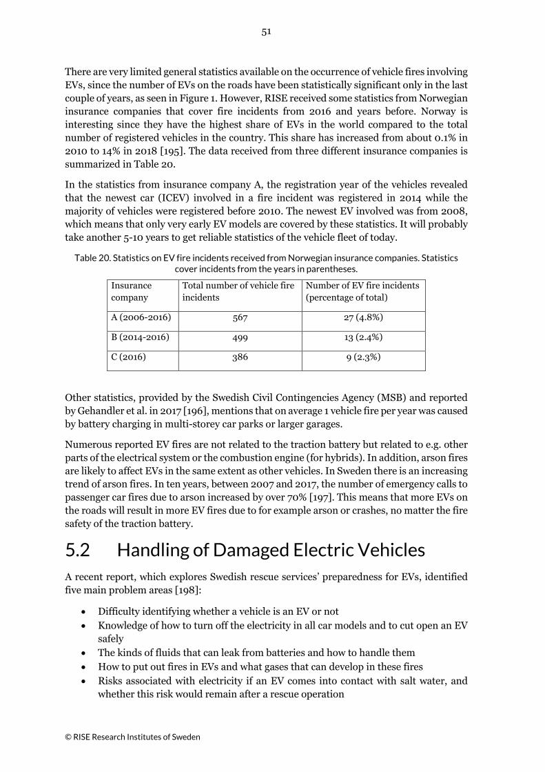
51
© RISE Research Institutes of Sweden
There are very limited general statistics available on the occurrence of vehicle fires involving EVs, since the number of EVs on the roads have been statistically significant only in the last couple of years, as seen in Figure 1. However, RISE received some statistics from Norwegian insurance companies that cover fire incidents from 2016 and years before. Norway is interesting since they have the highest share of EVs in the world compared to the total number of registered vehicles in the country. This share has increased from about 0.1% in 2010 to 14% in 2018 [195]. The data received from three different insurance companies is summarized in Table 20.
In the statistics from insurance company A, the registration year of the vehicles revealed that the newest car (ICEV) involved in a fire incident was registered in 2014 while the majority of vehicles were registered before 2010. The newest EV involved was from 2008, which means that only very early EV models are covered by these statistics. It will probably take another 5-10 years to get reliable statistics of the vehicle fleet of today.
Table 20. Statistics on EV fire incidents received from Norwegian insurance companies. Statistics cover incidents from the years in parentheses.
Insurance company
Total number of vehicle fire incidents
Number of EV fire incidents (percentage of total)
A (2006-2016) 567 27 (4.8%)
B (2014-2016) 499 13 (2.4%)
C (2016) 386 9 (2.3%)
Other statistics, provided by the Swedish Civil Contingencies Agency (MSB) and reported by Gehandler et al. in 2017 [196], mentions that on average 1 vehicle fire per year was caused by battery charging in multi-storey car parks or larger garages.
Numerous reported EV fires are not related to the traction battery but related to e.g. other parts of the electrical system or the combustion engine (for hybrids). In addition, arson fires are likely to affect EVs in the same extent as other vehicles. In Sweden there is an increasing trend of arson fires. In ten years, between 2007 and 2017, the number of emergency calls to passenger car fires due to arson increased by over 70% [197]. This means that more EVs on the roads will result in more EV fires due to for example arson or crashes, no matter the fire safety of the traction battery.
5.2 Handling of Damaged Electric Vehicles A recent report, which explores Swedish rescue services’ preparedness for EVs, identified five main problem areas [198]:
• Difficulty identifying whether a vehicle is an EV or not • Knowledge of how to turn off the electricity in all car models and to cut open an EV
safely • The kinds of fluids that can leak from batteries and how to handle them • How to put out fires in EVs and what gases that can develop in these fires • Risks associated with electricity if an EV comes into contact with salt water, and
whether this risk would remain after a rescue operation

52
© RISE Research Institutes of Sweden
Some of these problem areas were briefly covered in Chapter 4, where information was given on risks and challenges associated with EV firefighting. This information and guidance on safe procedures when responding to fires in EVs are available from various sources such as [199] [200] [201] [202] [203]. Further investigation into firefighting matters is not within the scope of the current project.
Matters which have not been discussed much in literature concerns post-crash towing, workshop, scrapyard and recycling activities. Personnel working in these fields do not have the same training or equipment as firefighting personnel has. This makes them, and their facilities, more vulnerable when a damaged EV reignites. The following sections will delve deeper into the challenges these industries may face in light of the ongoing electrification. In addition, available and relevant guidelines are reviewed.
5.2.1 Fire Hazards
Collision or crash by itself has the potential to cause the LIB to burn as shown by e.g. Böe [204]. This study investigated the risk for fire due to a strong rear end impact by dropping a custom-made EV from a height of 20 m. Upon impact, the vehicle reached a downwards velocity of 70 km/h. The impact then resulted in a large amount of smoke being released from the battery followed by a fire. Even though this work showed that certain impact conditions have the potential to cause a LIB to burn it should be mentioned that vehicle battery packs are normally tested against mechanical impact, e.g. as specified in UNECE Regulation 100, to ensure a high level of safety [124].
The crash of an EV in Ft. Lauderdale, USA, also illustrates the potential outcome of extreme crash conditions resulting in fire [131]. Here a speed of 86 mph (140 km/h) was recorded before impact according to the National Transportation Safety Board (NTSB) [205]. The report also states that this frontal crash engulfed the vehicle in flames and separated parts of the LIB from the vehicle. The fire reignited while the vehicle was being removed from the scene, which was quickly extinguished, and ignited again upon arrival at the storage yard. In another case where an EV crashed into an object at 70.8 mph (114 km/h) the battery caught fire and reignited on the same day at the impound lot and reignited again five days after that [206].
Fire is not necessarily the outcome of extreme crash conditions, however. In South Jordan, USA, an EV crashed into a heavy truck at 60 mph (97 km/h). There were no reports of fire despite the significant damage resulting from the frontal impact [207]. The extent of damage can be seen in Hattem [208]. Another case where severe crash condition did not result in a LIB fire is given by King [209].
It is however important to always carefully assess whether the battery may have been damaged as there are recorded cases where a minor crash has resulted in a delayed fire. A case that illustrates this well is the Chevrolet Volt fire in 2011 [174]. Here the National Highway Traffic Safety Administration (NHTSA) performed an NCAP side pole impact test on this vehicle to observe the extent of damage done to the battery. Significant damage to the vehicle was observed, yet damage to the battery pack went unnoticed at the time of the test. The vehicle was subsequently parked for more than three weeks, after which it caught fire. To determine the cause of this event, NHTSA investigated the incident followed by tests using the same or similar conditions as well as impact testing of battery packs. This showed that the crash test resulted in a transverse stiffener penetrating the battery, causing damage

53
© RISE Research Institutes of Sweden
to it, and rupturing its liquid cooling system [174]. Furthermore, the crash test protocol requires that vehicles are turned upside down to inspect for leakage of liquids, e.g. electrolyte or fuel. They found that this roll-over event can expose live energy components such as circuitry and wires to the conductive coolant. It was also shown that this can result in current flow through the coolant, resulting in electrolysis products in the battery pack and conducting particles to float on the coolant surface10. The latter was believed to have led to external short circuits in the wiring and circuit boards of the battery pack followed by ignition of combustible smoke and electrolysis products. From a handling perspective, this event illustrates what may happen when retrieving a crashed EV. It is however important to keep in mind the particulars of this event, namely the combination of certain crash and roll-over conditions as well as the fact that the battery pack was cooled by a liquid.
Submersion of an EV in salt or contaminated water may also be the cause for a fire to ignite in the battery pack. Examples of this are fires in several HEVs in the USA due to hurricane Sandy [175], fire in two electric buses in China due to heavy rain fall [210] as well as a recall of certain bus models in the USA [86]. If, for some reason, the individual battery cells are submerged in a conductive medium, e.g. contaminated water, salt-water or coolant, there is a risk for fire [210]. Salt-water may cause electrical arcing between the battery terminals, which may fuse the terminals together or potentially cause leakage of electrolyte. Note also that prolonged exposure to conductive and corrosive media, such as sea water, may cause damage to wires, wiring harnesses and other insulation materials which may result in exposure of live components.
Note that the use of carbon-fibre materials in modern EVs can pose handling risks. Please refer to Section 4.4.3 for discussion on this.
5.2.1.1 Mitigating Fire Risks
Reignition may not necessarily lead to problems when first responders are present, as they are trained to deal with such situations. It poses however a great concern to those that need to handle damaged EVs. There is a risk that the battery pack reignites during towing or after having been brought to a workshop, scrapyard or recycling site. A very important thing to consider when it comes to risk of reignition is that the heat generation occurs inside the battery pack. Hence it can be difficult to assess the risk by means of visual examination. Continuous temperature monitoring of the battery pack, e.g. using thermal imaging cameras or other temperature sensors, would be desirable as it will help to estimate the risk for reignition. Any local high temperatures on the battery pack may indicate a current or forthcoming cell failure, which may lead to reignition.
Long et al. [211]. employed both thermocouples and thermal imaging to monitor batteries during fire testing. Once the temperature had dropped to ambient levels, they ceased testing and left the batteries to rest for a period of 18 hours. This was to further ensure that any activity inside the battery had ceased. In two of the three tests they performed, they succeeded and there was no reignition of the battery. In the third case, the battery started making popping sounds during removal from the dummy EV, yet no evidence of combustion was noted. Four hours after having been transferred to a storage facility, it was noted that the battery released gas and flames inside the battery pack. The testing program
10 In one of the tests performed on the battery pack level this electrolysis event was paired with an audible boiling sound.
54
© RISE Research Institutes of Sweden
included extinguishment of the burning battery, and therefore there were likely still battery cells inside the battery pack not consumed by the fire. Fires in EVs where the battery pack has been completely consumed by the fire pose a lower risk for reignition. However, as showed by Böe [204], a fully developed car fire does not necessarily have to involve the battery, since the battery pack is generally well protected and situated in a low position which means less impact from heat and flames.
If an EV has burned or sustained damage that might have affected the LIB it should be isolated from combustible material in case of reignition or delayed ignition [147] [150]. This includes structures and other vehicles, and it should also not be stored in enclosed spaces where vented gases could harm people or build up a flammable mixture that can result in an explosion.
NFPA recommends that a vehicle containing a burned or damaged LIB is stored at least 15 m (50 ft) from structures, combustible materials or other vehicles until the battery is discharged [199]. They also recommend monitoring the LIB casing temperature using a thermal imaging camera if possible.
SAE advocates the following steps for storing damaged EVs [212]:
• Do not store the EV inside a structure until it has been inspected according to SAE J2990 procedures.
o An open perimeter isolation is an area in which all sides of the damaged vehicle (including the battery system) are at least 15 m (50 ft) from combustible materials, structures, and other vehicles, see [201] for details.
o A barrier isolation is an area where the vehicle is separated from all combustibles, structures, and adjacent vehicles by a wall made of non-combustible material. If the wall encloses 3 of 4 sides of the vehicle the open side must be at least 15 m (50 ft) from the nearest combustible material. It is not recommended to fully enclose the damaged vehicle due to the possibility of delayed fire/reignition or venting of harmful or explosive gases.
• Open the vehicle’s windows/doors for ventilation of potentially dangerous gases. • Do not expose the EV to rain or other precipitation if the LIB is ruptured.
EDUCAM, a knowledge platform and training centre for the automotive industry in the Benelux area, developed safety guidelines concerning the handling of EVs. These are available in French [213] and Dutch [214]. Their recommendations are split between general safety recommendations when working on EVs as well as specialised recommendations. According to the general guidelines [215], the first measure in handling of EVs is to perform an assessment. This assessment considers three things, namely the vehicle type, its condition and the potential hazards. Note that guidance on determining the vehicle type can be found in Sections 2.2, 3.3 and 4.4, whereas the potential hazards were discussed in Chapter 4 and here in Section 5.2.
The condition of the vehicle determines whether the vehicle may be parked in a regular parking spot or whether it needs to be moved to a designated location to be secured. This can be determined through consideration of Table 21. In brief, if the structural integrity of the chassis has been affected and fault codes have been recorded for the powertrain and/or BMS, or there are signs of water damage, the vehicle may no longer be placed in a regular parking spot and it must be secured before work can commence.
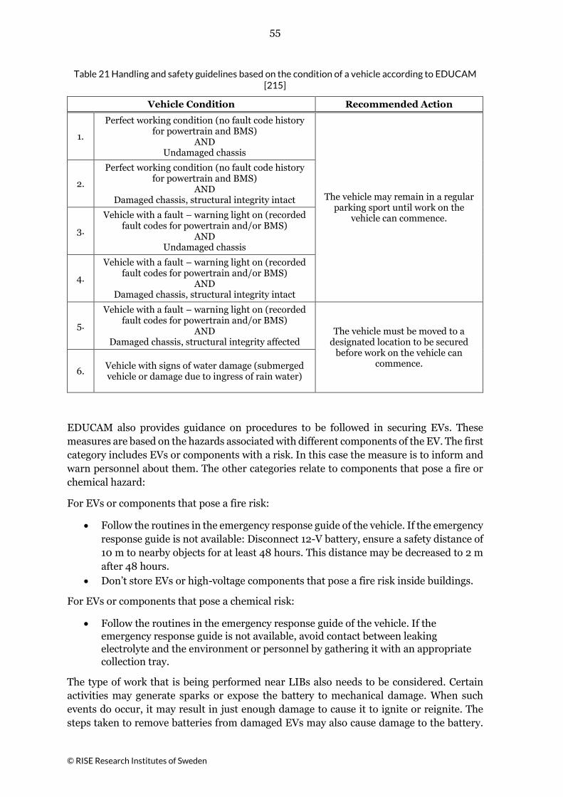
55
© RISE Research Institutes of Sweden
Table 21 Handling and safety guidelines based on the condition of a vehicle according to EDUCAM [215]
Vehicle Condition Recommended Action
1.
Perfect working condition (no fault code history for powertrain and BMS)
AND Undamaged chassis
The vehicle may remain in a regular parking sport until work on the
vehicle can commence.
2.
Perfect working condition (no fault code history for powertrain and BMS)
AND Damaged chassis, structural integrity intact
3.
Vehicle with a fault – warning light on (recorded fault codes for powertrain and/or BMS)
AND Undamaged chassis
4.
Vehicle with a fault – warning light on (recorded fault codes for powertrain and/or BMS)
AND Damaged chassis, structural integrity intact
5.
Vehicle with a fault – warning light on (recorded fault codes for powertrain and/or BMS)
AND Damaged chassis, structural integrity affected
The vehicle must be moved to a designated location to be secured
before work on the vehicle can commence.
6. Vehicle with signs of water damage (submerged vehicle or damage due to ingress of rain water)
EDUCAM also provides guidance on procedures to be followed in securing EVs. These measures are based on the hazards associated with different components of the EV. The first category includes EVs or components with a risk. In this case the measure is to inform and warn personnel about them. The other categories relate to components that pose a fire or chemical hazard:
For EVs or components that pose a fire risk:
• Follow the routines in the emergency response guide of the vehicle. If the emergency response guide is not available: Disconnect 12-V battery, ensure a safety distance of 10 m to nearby objects for at least 48 hours. This distance may be decreased to 2 m after 48 hours.
• Don’t store EVs or high-voltage components that pose a fire risk inside buildings.
For EVs or components that pose a chemical risk:
• Follow the routines in the emergency response guide of the vehicle. If the emergency response guide is not available, avoid contact between leaking electrolyte and the environment or personnel by gathering it with an appropriate collection tray.
The type of work that is being performed near LIBs also needs to be considered. Certain activities may generate sparks or expose the battery to mechanical damage. When such events do occur, it may result in just enough damage to cause it to ignite or reignite. The steps taken to remove batteries from damaged EVs may also cause damage to the battery.

56
© RISE Research Institutes of Sweden
Training systems and requirements on the qualifications of the personnel performing such critical tasks is one way to control and reduce the risk. In addition to this, technical documentation on the vehicle that is being dealt with will prove useful. However, depending on the level of damage the best approach could be to de-energize the battery before handling. Possible approaches could be to immerse the battery or vehicle in salt-water or to use an external load, however, fire risks will increase during discharge event (if not immersed in water).
5.2.2 Electrical Hazards
The likeliness of the vehicle chassis to conduct current from the high-voltage system is low. This system is isolated from the chassis unlike the conventional 12/24/48 V system. A so-called floating ground that the battery system employs, guarantees that there is no connection to the chassis. As a result, touching a live part of the high voltage system will normally not cause current to enter a person’s body. This is only possible when contacting both the plus and minus sides of the battery system simultaneously [47].
When the vehicle is being charged, the charging point may connect the vehicle to ground [47] [21]. Beyond the converter, between the battery and the charging point (which is normally found in the charging station), the vehicle system is still not part of the main grid and thus separated from ground. However, the first charging mode, Mode 1 (see Section 2.3), does not have means to communicate with the vehicle, does not ensure any built-in protection systems and does not normally connect to a dedicated circuit. There is no guarantee that undedicated or private circuits are equipped with protective systems such as a residual current device. In that case, without protective systems, the risk for electrical injury or risk of fire are significant [216] [217].
A special case concerning charging is when an EV is submerged in water while still being physically connected to a charging point. In that case, the Dutch Institute for Safety (IFV) discusses that there is a risk for current on the vehicle structure [218].
5.2.2.1 Mitigating Electrical Risks
EVs are unlikely to pose a significant electrical threat. It is however recommended to physically disconnect any charging point from an EV before handling them, specifically in case of an incident. Another important aspect in case of a traffic incident lies in securing the vehicle, such that it will not move. This step is needed to negate the risk of the vehicle driving off or rolling away, which can be achieved by physically blocking their wheels, engaging the parking brake or putting the EV in park. Here it is important to keep in mind that EVs may appear to be shut-off, even when they are not, due to the lack of engine noise.
An EV will automatically disconnect the battery system from the powertrain if the vehicle is turned off or if the BMS senses a level of impact or abuse of the LIB. In special cases it may be necessary to perform this disconnection manually. If the vehicle is off and there is access to the 12/24-volt battery, disconnecting the battery cables or removing fuses will prevent it from starting up but will not necessarily shut off the vehicle if it is already on [147]. If the 12/24-volt battery or fuses are not accessible, the high voltage system may be disconnected. However, this is not a simple procedure due to the many different possible configurations and locations of the main voltage disconnect.

57
© RISE Research Institutes of Sweden
Some general guidelines on how to safely disconnect the high-voltage battery pack are summarised in Table 22. Guidance can also be found in e.g. NFPA’s Hybrid and electric vehicle emergency field guide [199] or emergency response guides [219].
Table 22 General guidelines on measures to be taken to safely disconnect the LIB.
SAE International [212] ARN (Car Recycling Netherlands) [220]
1. Vehicle shall automatically shut itself down based a sensed level of impact.
2. Turn the ignition switch or power button to the off position (assuming critical battery circuits are not damaged).
3. Cut or disconnect the 12-volt battery cables and the DC/DC converter’s 12-volt cable, and/or
4. Remove the manual disconnect (high voltage main disconnect). This action requires knowledge of the vehicle’s high voltage main disconnect configuration.
1. Mark the EV to inform about work being performed on high-voltage systems.
2. Put the EV in park-mode, remove the ignition key or deactivate it using the power button. Store the key at least 10 m from the EV.
3. Disconnect the 12V battery from ground. 4. Remove the service disconnect plug of the
high-voltage battery using electric insulating gloves. Always have the plug with you.
5. Wait at least 10 minutes for the capacitators to discharge.
6. Measure whether the voltage has dropped to 0 V using a suitable voltage detector.
Additional protection against electrical hazards can be provided through the use of protection equipment. According to EDUCAM [215] this can be in the form of personal protection, such as gloves or facial protection, collective protection, or tools and equipment. Examples of these have been summarised in Table 23. Note that emergency response guides can also be consulted for information on this.
After successfully disconnecting the LIB and de-energising the high-voltage system, safe working conditions on the high-voltage system are normally guaranteed as the built-in safety systems mitigate any risk for contacting live parts or the chance for electrical arcing. It is very unlikely that these systems are not present in modern EVs. If, for some reason, such safety systems are not in place then there are some measures that can be taken according to EDUCAM [215]:
• Connect the high-voltage system to ground, discharge capacitators and short circuit the high-voltage system.
• Insulate components nearby the high-voltage system and those carrying current.

58
© RISE Research Institutes of Sweden
Table 23 Personal and collective protection as well as safety equipment needed when working on EVs according to EDUCAM [215]
Personal protection
Electrical insulating gloves Gloves that provide protection against mechanical hazards Gloves that are resistant against chemicals Safety shoes Electrical insulating shoes Electrical insulating clothes Eye and facial protection
Collective protection
Locks, signs and warnings Barriers, warning tape, flags
Equipment
Two-pole voltage detectors Electrical insulating tools Electrical insulating blankets Electrical safety matting

59
© RISE Research Institutes of Sweden
6 Safety Solutions In this chapter the fire safety of LIBs in vehicles is examined from three perspectives. First, a holistic approach is presented, including safety precautions at different levels of the battery and vehicle system. Secondly due to the scope of the project, fire detection and suppression is discussed separately. Finally, this chapter includes results from a workshop organized within the project with a prevention-recovery perspective, meaning that prevention of fire or thermal runaway was discussed separately from recovery or mitigation of a fire or thermal runaway.
6.1 A Holistic View There are many levels of fire safety to consider in an EV. In an ideal situation, the individual battery cells would be designed to prevent short circuits and other malfunctions that could lead to overheating and thermal runaway. The cells are arranged in modules that, ideally, would be designed to prevent propagation of thermal runaway among the cells. The modules would be placed in a battery pack that would be fitted with safety system(s) that could detect the possibility of fire and act to prevent it or, if a fire has started, extinguish it before it causes extensive damage to the battery, the vehicle, or the passengers. The battery management system (BMS) would be able to handle all threats to the battery, both internal and external, and interact efficiently with the other safety systems in the vehicle as needed. In addition, the design of the vehicle itself would ideally include safety precautions that address the protection of the battery pack(s) in case of impact [221].
The fire safety system levels are shown schematically in Figure 43, where the core of the concentric circles denotes the most basic component of the battery: the chemistry within each cell. Thereafter comes cell design and packaging, short circuit protection including current limiters, battery contactors, the BMS, system design and housing, and thermal management. The outermost circle represents the integration of battery fire safety into the design of the vehicle [134] [43]. According to Ahlberg Tidblad [124] most battery and vehicle manufacturers consider all these safety levels, which is normally ensured by extensive testing programs for vehicle approvals.
Figure 43 Schematic diagram of battery fire safety system levels for EVs. Copied from [134] [43].

60
© RISE Research Institutes of Sweden
6.1.1 Battery Cell Level
Safety solutions at the cell level includes chemical/physical safety devices for the cell and monitoring of the cell. Safety devices designed for cylindrical and prismatic cells include current limiters such as positive temperature coefficient (PTC) and current breakers such as current interrupt device (CID) [37] [222]. The former varies the resistance by temperature, while the latter breaks the circuit in case of increased internal pressure within the cell. This to prevent over-pressure situations that could lead to venting of gases. In case of thermal runaway, gases and other materials that could be ejected from a cell are forced through vent valves which may include a tortuous path, a flame arrestor, or a backflow preventer to remove heat and direct the gases in a more controlled way to protect surrounding cells [154]. Pouch cells cannot use these devices but can have deliberate weak spots designed into the pouch to allow gases to vent in a more controlled way. In addition, e.g. wire bonding could be used as an electric fuse within the cells to reduce the energy released during an internal short circuit [154].
Efforts to improve the safety of the cells by using materials with intrinsically better thermal properties include using flexible ceramic separators [223] or other types of modified separators to prevent separator failure and/or minimize thermal shrinkage of the separator [37] [154]. Less flammable or non-flammable electrolyte material can limit heat production due to flames and using filler materials with increased thermal capacity, such as phase change materials, can help to dissipate or cool the cells. Finally, solid state batteries have no liquid or flammable electrolytes, thereby reducing the risk of gassing/venting and fire [154].
The main source of oxygen in a LIB is the cathode, which releases the oxygen when it breaks down during thermal runaway. Treatment of the cathode with transition metals increases the temperature at which thermal runaway occurs and thus can contribute to the thermal stability of the cell [47] [196].
There are numerous safety schemes that involve monitoring of cells’ condition. These schemes generally come from the consumer LIB industry and may not be feasible for the large format batteries used in vehicles because they tend to increase the weight, volume, and cost of the battery system [224]. Nevertheless, it is possible for the BMS to monitor each cell’s condition and compensate to some extent for anomalies in e.g. impedance, temperature, current and voltage [37] [196].
6.1.2 Battery Management System (BMS)
The BMS monitors and regulates the cells to optimize their energy output and ensure that the battery system is working within safe operating conditions. A relatively sophisticated BMS might be integrated into other vehicle safety systems or the BMS can be relatively simple and operate independently. Typically, the BMS monitors at least the total battery current, the total battery and individual cell voltages, and the temperature at numerous places within the module [163], however in vehicles it is common with just one temperature sensor per module as the number of sensors in a LIB module is typically minimized to reduce the cost, weight, and volume of the module. Therefore, it is possible for an individual cell to overheat and vent without timely detection if a temperature sensor is not located near enough to the cell. The BMS can act if necessary, to mitigate some problems, e.g., the BMS can shut down the module or the battery pack if a temperature sensor indicates an

61
© RISE Research Institutes of Sweden
overheating situation [37]. Table 24 provides an overview of conditions in which the BMS can or cannot respond to protect the battery system. According to [196] the BMS, in general, automatically disconnects the battery system in response to the following situations:
• Too high temperature • Under-voltage • Over-voltage • Over-current • Failure of the battery’s cooling system • Damaged and/or falsely triggered crash sensor • The vehicle has begun to overturn (as detected by the sensor) • Insulation failure • Current fault, such as arcing
Table 24 A simplified general overview of abuse situations where the BMS can/cannot protect the battery system. Reproduced from [43].
Abuse type BMS protection? Protection strategy
External battery pack short circuit Yes Disconnect the battery by using fuse or possibly
contactors
External cell short circuit Possible* The BMS can protect if the short circuit current is
possible to interrupt by a circuit breaker
Internal cell short circuit No**
Overcharge Yes*** Disconnect the battery by using contactors
Overdischarge Yes*** Disconnect the battery by using contactors
Mechanical cross/ deformation/ penetration
No
External heating, mild Yes Cooling by using thermal management system
External heating, strong No
External fire No
* This case refers to a situation with an external short circuit of one or multiple cells inside the battery pack. Theoretically, many short circuit paths are possible, and if the short circuit happens to be within a current path involving a fuse or possible contactors then it is possible to stop the short circuit. ** Spontaneous starting on micrometre scale inside the cell due to, e.g., particle contamination or dendrite formation. *** The detection and the consequent actions until current shutdown must be rapid enough to ensure that the battery is not exposed to over/under voltages.
Faults can happen both with the sensors and within the BMS. Given the importance of the BMS, it is particularly advisable to include methods of validating its performance. Redundant sensors of all types (voltage, current, temperature) would enable the detection of sensor and BMS faults and would improve the capacity of the BMS to detect and respond to potential problems [43]; however, the cost, size, and weight of the battery system would also increase [163].
62
© RISE Research Institutes of Sweden
6.1.3 Battery Module Level One way of preventing the propagation of thermal runaway from cell to cell is to design the modules so that it is difficult for heat to be transferred between the cells. This can be accomplished by having open space between the cells, using heat shields or insulators [225], cooling plates, heat conductors, flame retardant barriers, intumescent coatings, and phase change materials. The method of choice depends heavily on the specific end use of the battery system, the cell type, the module configuration and may also include numerous other thermal propagation prevention measures [222]. As with the individual cells, vents can be placed in the module to control emitted gases, arrest flames [225] and reduce or prevent oxygen intrusion from outside the module [154].
The wiring inside the module can be designed to reduce the risk of thermal propagation. The tabs that connect the cells to each other can be located strategically and e.g. be configurated such that they breach if overheated. For several cells in parallel the tab connection configuration can be either branched or in series. The branched configuration has been showed to improve safety due to that an affected cell is electrically better isolated from the other cells [222].
The module can be designed to have its own dedicated thermal management system and/or inert gas system if space, cost, and weight constraints allow [154].
6.1.4 Battery Pack Level Many of the same safety solutions that apply to the modules can also be applied to the battery packs. Examples of these solutions include providing heat transfer barriers between the modules, strategically placed vents in the battery pack wall, and having a dedicated cooling and/or inert gas system [43] [154].
A large battery system can be divided into several smaller packs that are thermally isolated from each other, which provides a level of safety against large-scale thermal propagation. In addition to these safety precautions, the battery pack casing can also be structurally designed for enhanced crash protection [226].
Areas housing the LIB in electric vehicles must be designed in such a way that direct impact or penetration of the high voltage battery modules is prevented [128]. For electric passenger cars, severe deformation is currently being prevented by placing battery packs in reinforced locations, ensuring structural protection and limiting their size [46], see as well chapter 3 for discussions about LIB placement in passenger cars, buses and heavy trucks.
Battery packs could be provided with additional reinforcements to reduce potential intrusion during certain impact conditions. The EU study OSTLER considered two different approaches to achieving this, namely passive and active protection. These techniques refer to enhancing the physical strength of the structure or making use of inflatable structures to spread the load during a crash event, respectively [130]. Using these methods, they were able to reduce the amount of intrusion by 26 % with active protection and by 58 % using passive protection.

63
© RISE Research Institutes of Sweden
6.1.5 Vehicle Level
The results of the EVERSAFE EU project indicate that the overall level of safety of EVs is relatively high [128]. They did not identify any critical issues related to the LIB. In fact, they found that there is little chance that an EV crash results in fire or the emission of toxic gasses or liquids. They identified that the primary need in EV safety lies in assisting fire fighters in the identification of EVs, disconnecting electrical systems and neutralising batteries after a crash.
EVERSAFE also gives several recommendations related to vehicle/battery design in Deliverable No. 3.1 [58]. A selection of these recommendations that relate to the design of the battery pack/vehicle are listed in Table 25. In regard to undercarriage impact, Tesla reinforced the battery pack of their Model S after a fire caused by ground impact [227]. In addition to reinforcing the pack, they installed a deflector plate/front shield.
Table 25 A selection of the recommendations based on the simulation work and other familiar studies by EVERSAFE [58].
Front pole impact
Optimise the front structures, where there is no combustion engine, to build energy absorbing structures especially for pole intrusion between frame rails.
Undercarriage impact
Use of the front shield. Reinforce the protective structure of the pack.
Battery placement
Floor placement is advantageous as it is wide for a large battery and improves the dynamic behaviour of the car.
Battery design Better protected liquid cooling system inside the battery or use a non-liquid cooling system. A rupture of the coolant system could cause a short-circuit with surrounding electric components.
In the design of vehicles, it is also important to consider the placement of high voltage components. Ideally these components will not be affected in collisions for example. Freschi et al. provide some suggestions such as flexible conduits, routing high-current cables underneath the vehicle floor and to locate the battery terminals as far away from each other as possible to minimise the risk for possible contact [21].
Justen and Schöneburg [48] present a seven-stage safety concept implemented in Mercedes-Benz, namely:
1. Colour-code and contact protection for all high voltage wiring with ample insulation and special plugs,
2. High-strength steel housing for the lithium-ion battery located well protected in the extremely stiff zone before the fire wall,
3. The battery cells are bedded in a shock absorbing gel, with a separate cooling circuit and a blow-off vent with burst disk,
4. Multiple safety interlock to automatically separate battery terminals, 5. Continuous short circuit and malfunction monitoring, 6. Active discharge of the high voltage system in the event of faults or fire, 7. Pyrotechnical tripping of the voltage system in the event of an accident.
There are also external safety precautions to be taken to ensure that damage to the surroundings is minimized in the case of an EV fire or battery failure. This includes considering the value of slowing or delaying thermal propagation, the placement of charging stations in parking lots, how a damaged vehicle can be de-energizing, concerns regarding

64
© RISE Research Institutes of Sweden
battery fire extinguishment and proper storage of a burned or damaged EV. Handling of damaged EVs including storage and de-energizing is covered in section 5.2.
In lieu of the fact that it can be very difficult to stop the propagation of thermal runaway inside a battery pack mounted in a vehicle, slowing or delaying the propagation using some of the safety solutions discussed in this chapter may be a reasonable approach. This could give more time for detecting the problem and responding to it [43]. It might also make it possible to isolate the vehicle, evacuate people and prepare for the fire service to arrive.
Since EVs are usually charged while they are parked, the design of parking lots (especially underground or multilevel parking lots) should consider the safest placement of charging stations. Locating charging stations near ingress/egress points or other locations that have good ventilation and access to an adequate supply of extinguishing water may help to minimize hazards associated with venting gases and fires [228]. This requires careful consideration, however, as placing EVs near evacuations routes could potentially complicate emergency evacuation procedures.
6.2 Fixed Fire Detection and Suppression Systems
Fixed fire detection and suppression systems are here considered to be on-board vehicle systems with fix installation. Such systems are widely used to protect engine compartments on heavy vehicles, for example, 94% of all public transport buses in Sweden have fixed fire suppression systems installed [229] but they are not common in passenger vehicles. Background to what possibilities these systems have in terms of fire protection for LIBs is provided below. The discussions are not restricted to only on-board vehicle systems, where the limited amount of suppression agent is crucial, but include a more general approach regarding fire detection and suppression of LIBs.
6.2.1 Detection Researchers have developed models based on various measurable conditions, such as temperature, moisture, voltage, resistance and current to predict potential internal short circuits and fire [230] [231] [232] [233]. Given a good understanding of how catastrophic failures can occur, it may be possible to monitor the status of key cell/module/battery pack characteristics that could provide input to predictive models that can warn the BMS or other vehicle safety systems if conditions are right for a potential failure.
There are complicating factors in detection of fires or impending fires in a LIB, even if their source is well understood. For example, the number of sensors in a LIB module is typically minimized to reduce the cost, weight, and volume of the module, and therefore, it is possible for an individual cell to overheat and vent without timely detection if a temperature sensor is not located near enough to the cell. The BMS normally monitors each cell voltage, but there are several reasons, including thermal runaway and fire, why the cell voltage could drop. Conversely, in the case of a fire or gas release, the cell voltage may or may not change [134].
The US Navy have had a LIB safety program since 1979 and have done extensive research in collaboration with commercial interests and other US laboratories on detection options. They are leveraging a priori early detection in commercial systems and prototypes that are

65
© RISE Research Institutes of Sweden
based on monitoring the signatures of various aspects of cells, modules and battery packs, such as voltage, current, resistance, impedance, magnetic fields, strain, pressure, temperature, moisture, gas and particle emissions, and thermal, acoustic, and optical properties [234].
Remote detection systems (outside the battery pack) that are currently being investigated by the US Navy can operate without a direct interface with the battery but can also be integrated into a BMS. These systems are based on physics, such as: “sniffing” chemicals that have escaped the battery pack, which assumes leakage of a module and battery pack and failure of at least one cell; use of an electroactive polymer as the separator between the anode and cathode of a cell that could send a magnetic signal to a remote detection system if the cell has an internal short circuit; and detection of acoustic, electric, or magnetic changes within a cell, module, or battery pack [234].
The US Navy is also working on detection technologies that are integrated into the battery systems. These systems involve monitoring of resistance and impedance using an in-situ electrochemical impedance spectrometer; and measuring the strain, pressure, gas generation, and volume changes of pouch cells [234].
Placement of sensors within the LIB module or battery pack to detect hydrocarbons, such as those coming from electrolyte solvents, or toxic gases associated with cell failure, such as hydrogen fluoride may also provide an indication that something is wrong within the module [235].
6.2.2 Suppression A LIB fire should be cooled at its source, i.e. the cells inside the module. However, access to the seat of fire can be difficult because the modules and battery pack are compactly designed with a high tightness level (e.g. IP67). Battery packs could also be located in places that are difficult to access. Much testing has been conducted on individual cells, but the most severe challenge lies in extinguishing fires inside the battery packs. Research and fire testing of cells, modules and battery packs have resulted in many different ideas about the best way to extinguish a fire in a LIB, which is evident in the following quotes and sub-section.
“If an HV battery catches fire, it will require a large, sustained volume of water.” [199]
“Dry chemical, CO2, and foam are often the preferred methods for extinguishing a fire involving batteries, and water is often not the first extinguishing agent of choice.” [236]
“Firefighting techniques for vehicles using Li-ion battery packs should be treated like any electrical fire by using Class C extinguishing agent.” [237]
Uncertainty prevails about the type of extinguishing agent or system that is most appropriate. Part of this confusion stems from the similarity, in name only, between lithium-ion and lithium metal batteries. Today, the former is rechargeable, whereas the latter, sometimes referred to as lithium batteries, is non-rechargeable. When exposed to water, these batteries may react exothermically. Water can however be used to extinguish fires in LIBs [163].
When it comes to extinguishing LIB fires, suppression agents having the ability to remove heat from the cells/module and thus inhibit the propagation of thermal runaway appear to be most positive. In a realistic LIB fire there are flames present that should also be

66
© RISE Research Institutes of Sweden
extinguished; however, extinguishment of flames must be balanced against the possibility that there could be a build-up of flammable gas that leads to an explosion if the cells vent without an open flame nearby [163].
Propagation of thermal runaway occurs when a cell in thermal runaway heats an adjacent cell and causes it to react and experience thermal runaway as well. The chain reaction could make a series of cells become progressively hotter and more difficult to extinguish [238]. The use of thermal barriers, firewalls, and cooling plates can affect thermal runaway but have the disadvantage of adding weight and size to the module. Also, the thermal situation could become worse if insulation prevents heat from being removed from the cells [163]. Thermal runaway is very difficult to stop, sometimes it cannot be stopped even if there is access to the inside of the LIB module. Thermal runaway propagation can go on for several hours and possibly starting many hours after the initial damage took place. It is difficult to judge whether or when an extinguished fire will re-ignite or when a fire might start in a vehicle that has been damaged [147].
Plain water is a common firefighting agent which is environmentally friendly and Larsson and Mellander [43] state that it is likely to be suitable for LIB fires, since it offers excellent cooling capability. They suggest that a water flooding system for the battery pack might be a viable solution, even though there are potential negative effects, e.g. short circuits and toxic run-off water.
Andersson et al. [163] propose that water should only be applied if thermal runaway is taking place, since short-circuits are not as high a priority at this point. They also suggest that modules should be designed so that thermal runaway in one cell does not cause thermal runaway in neighbouring cells, in which case there is less need to apply water inside the battery pack.
According to DNV GL, the ideal battery fire extinguisher would be both highly thermally conductive and highly electrically insulating. Water is the former but not the latter. Deionized water is both until it dissolves contaminants from the fire, including ash and soot [165].
In 2011, based on previous work by Reif et al., Lisbona [239] recommended using an ABC dry chemical extinguisher or water on lithium-ion batteries, depending on which other materials that might be involved in the fire.
6.2.2.1 Fire Suppression Tests
The National Fire Protection Association (NFPA) reports that fires in electric and hybrid vehicles require both more water and longer extinguishing time than conventional car fires [160]. In their work, extinguishing hybrid cars required 1-4 l of water and a quenching time of 15 – 56 min, while quenching BEV fires required 4,4-10 l of water and a quenching time of 36 – 60 min. By comparison, a conventional car fire is normally extinguished within 5 minutes [228].
An idea about creating access to the LIB pack was proposed by a French research group that included Renault [240]. The fire safety of two of Renault’s EV models was tested and they found that a fire inside the battery pack could not be extinguished using water unless the water could flood the inside of the pack. In response to these test results, Renault designed a temperature sensitive hatch located under the rear passenger seat for accessing the battery pack. The hatch melts if the battery overheats or ignites, giving first responders access to

67
© RISE Research Institutes of Sweden
the inside of the battery pack. Safety issues with this solution were preliminarily shown to be negligible.
Assuming there is access to the inside of the LIB pack(s), Andersson et al. found that agents with a high heat capacity, such as water and low expansion foam, provide rapid cooling and fire extinguishment [241]. They found that reducing water surface tension could make it easier to wet surfaces deep inside the module but agents with high viscosity may not be able to spread to the seat of the fire. The agents they tested with less heat capacity, such as high expansion foam and nitrogen gas, provided less cooling but could still extinguish the fire if introduced into the battery pack correctly.
In individual battery cell fire suppression tests by Luo [242], two aqueous fire suppressant solutions, one with 5 % of “F-500”® and the other with 5 % “anionic non-ionic surfactant”, were shown to extinguish LIB fires in half the time of pure water mist, and also prevent reignition. In these tests the cells were at 50 % SOC and were punctured to initiate the fire.
Flame retardant (FR) that is micro encapsulated in a polymethyl methacrylate (PMMA) shell and is integrated into the LIB electrolyte and/or coated on the separator has been found to be very effective in self-suppression of LIB cell fires [243]. When the cell reaches a critical temperature, the liquid FR evaporates while the PMMA capsule wall weakens so that the FR is released into the cell. The FR causes the cell temperature to decrease significantly, preventing thermal runaway and extinguishing the fire. The presence of micro capsules did not inhibit the electrochemical performance of the cells. The FR can be selected based on cell chemistry. A challenge to this type of suppression system is that charging the batteries causes their internal temperature to increase, sometimes to rather high temperatures depending on the specific charging system.
In DNV GL’s testing of water-based extinguishing agents, including PyroCool®, F-500®, and FireIce®, it was found that the tested media could have an equal or lower cooling effect than water, but all were electrically conductive due to their reliance on water as a dispersion medium [165]. Gases and aerosols did not cool as well as water due to their lower thermal mass, relatively poor thermal conductivity, and restricted access to deeply seated fires. It was found in this testing program that water cools best, with the potential unwanted side effect of short-circuiting other cells, and that the amount of water required for extinguishment is dependent on the water contact efficiency with the cells.
Fire tests were performed by Russo et al. [244] on individual cells using CO2, foam, powder, pure water, and water mist as suppressants. For the individual cells, pure water and foam were found to be the most effective suppressants, due to their ability to reduce the temperature of the fire very quickly. They also did a single test on a battery pack using water as the suppression agent but did not report the results of this test. The spacing of the pouch cells in the module were adjusted to minimize transfer of heat from one cell to the other.
Water with abrasive additives, together with surfactant, has in some experiments proven to be effective [245]. Additives can change the properties of water in different ways, depending on what is added. If the water is made more viscous, one theory is that the cooling effect could be increased because the water does not flow away from the hot surface as quickly, which conflicts with the idea that viscous fluids cannot easily reach the seat of the fire. Alternatively, if a surfactant is used to reduce the surface tension, water could wet surfaces more easily [228].

68
© RISE Research Institutes of Sweden
Egelhaaf et al. [167] conducted fire tests in which three identical large format 17 kWh EV Li-ion batteries were exposed to heptane pool fires. The batteries were placed in a rack with a pan for the pool fire below. After about 8 minutes the batteries started short circuiting and releasing gases and particles; they continued to burn after the heptane was depleted. The batteries were then extinguished with pure water, water with 1 % F-500®, and water with 1.8 % Firesorb® in it. They found that much less water was needed when using the F-500 and Firesorb® solutions (80 l and 120 l, respectively) compared to pure water (400 l), although they caution that it may be difficult to flow large volumes of water on a battery pack that is actually installed in or under the vehicle.
6.2.2.2 Untested Suppression Ideas
Extinctus AS in Norway is working on a water emersion system in which burning EVs in high risk locations such as ferries, car parks, charging stations, etc can be effectively neutralized. Their system is under development and awaiting validation testing [246].
Lebkowski [247] proposes using temperature, flame, and impact sensors that send instructions to disconnect the battery and release suppressant into the battery module when conditions indicate that a fire is imminent or has occurred
Considering the phasing out of fluorinated substances such as R134a that have been used as refrigerants in vehicles, CO2 has become a contender as a replacement technology. Kritzer et al. suggest basing a redundant and independent emergency cooling system for overheated LIB batteries in EV on CO2 [248].
6.3 Hazard Identification Workshop A hazard identification (HazId) workshop was held in Stockholm, 6-7 November 2018. A HazId workshop is a systematic brainstorming session carried out by a multidisciplinary team, to investigate the safety of a specific subject. The selected participants should mirror the diversity of the subject in the sense that they should possess all the necessary competence to identify potential hazards and safety measures for the specific subject. The focus of this HazId was “fire safety of vehicle LIBs and effect on surroundings” and the experts gathered are presented in Appendix B, along with their expertise in particularly battery design, vehicle integration, testing, risk analysis, battery handling, electrical safety, fire safety and fire protection.
6.3.1 Method
A spreadsheet was developed prior to the HazId workshop, to guide the procedure and for documentation of results. The spreadsheet and the HazId procedure were based on a bow tie model as seen in Figure 44.

69
© RISE Research Institutes of Sweden
Figure 44 Bow tie model
Initially, different interesting states of the vehicle and surroundings were identified as:
• Journey • Parked • Charging • Collision • Extreme heat or cold • Workshop (incl. dismantling) • Salvage, towing and jumpstart
For each state, causes that can lead to thermal runaway or fire were identified along with potential safety measures as well as already existing safety for prevention of the event.
For the recovery phase, the desired functions and affecting conditions were identified to assist in the process before starting to identify challenges and potential safety measures. This procedure was repeated for all system levels of thermal spread such as between cells, between modules, from battery pack to vehicle and from vehicle to surrounding environment. Along with the entire process a list of related comments was noted as well.
6.3.2 Results
The resulting documentation from the hazard identification workshop is presented in Appendix A.
Some notable discussions/questions from the workshop were:
• The large diversity of different battery solutions and battery placements. How to easily access this information?
• The central role of the battery management system (the BMS). It is generally tested rigorously by the vehicle manufacturer for the intended purpose, but what about second use applications?
• The lack of guidelines on how to handle damaged vehicles: o Safety clearance?

70
© RISE Research Institutes of Sweden
o Safe location? o How to extract energy from the battery? o Should the vehicle be handled different depending on level of damage? o How long time before starting to handle the vehicle?
• The challenge of early failure detection and state of health (SOH). SOH is today focused on performance issues due to e.g. aging, but how can reliability be assured after e.g. a collision?
• Is an extinguished fire always the best alternative? Without fire there might be risk of gas explosion in case of battery venting. With controlled ventilation of gases to the outside of the vehicle this is mainly a risk in confined spaces, such as a garage.
• The challenge to achieve effective cooling of the battery cells to break thermal runaway chain reactions.
• Charging and especially fast charging stress the battery, however, with high quality BMS the risks are not higher than during driving, apart from risks arising from charging at home without charging station. Common electrical systems are not designed for long-term charging.

71
© RISE Research Institutes of Sweden
7 Conclusions This report addressed concerns on the fire safety of road vehicles with lithium-ion batteries (LIBs) by review of available literature. Fundamental information on EVs and LIBs was presented, and matters related to fire risks and safety solutions were investigated. It covered areas such as battery pack integration in vehicles, identification of fire hazards and means for preventing and controlling LIB fires. The suitability of fixed fire suppression and detection systems in EVs and measures to prevent consequences to the surroundings in case of an EV fire were also investigated.
Statistics show that the demand for EVs has increased strongly in recent years and that this trend continues. Common for most EVs is their energy storage method: LIBs. There are however many variations on LIBs, with different packaging and chemistries but also variations in how they are integrated into modern vehicles. The number of individual cells, and the types used, depend on the needed performance. To use LIBs safely means to keep the cells within a defined voltage and temperature window. These limits can be exceeded as a result of crash or fault conditions and thus damage the LIB causing them to vent and burn. Gases released in this process may be a threat to personnel, especially when allowed to accumulate. First responders and post-crash handlers need to be aware of the possible risks posed by EVs and how to handle them. It is therefore important that first responders are able to identify EVs and their LIB easily; a task which can be challenging given current standards. Only after this the risk can be assessed and appropriate guidelines and working procedures followed.
Incidents involving EVs continue to attract considerable media attention, which could rise caution among responders and the public. There is no denying that EVs are accompanied by new risks, but there is no evidence that points at EVs being less safe than conventional vehicles. Automotive LIBs are also inherently safer than those used for small consumer applications. This is achieved through chemistry, design and high-quality Battery Management System (BMS). However, failures will happen and will become more common with increased number of EVs. The way forward is to take on this challenge through measures and safety systems that bring risks down to acceptable levels. Only then will society achieve the same comfort level for EVs as they have for conventional vehicles.
72
© RISE Research Institutes of Sweden
8 References
[1] N. Nitta, F. Wu, T. Lee and G. Yushin, “Li-Ion Battery Materials: Present and Future,” Materials Today, vol. 18, pp. 252-264, 2015.
[2] International Energy Agency, “Global EV Outlook 2018,” International Energy Agency, 2018.
[3] European Alternative Fuels Observatory, “Total Number Alternative Fuels Passenger Cars: AF Fleet (Electricity) (2019),” 29 October 2018. [Online]. Available: https://tinyurl.com/y9g45w6p. [Accessed 1 February 2019].
[4] International Energy Agency , “Nordic EV Outlook 2018 - Insights from Leaders in Electric Mobility,” International Energy Agency, 2018.
[5] European Alternative Fuels Observatory, “AF Fleet (2018),” 29 October 2018. [Online]. Available: https://tinyurl.com/y8p9myxx. [Accessed 1 February 2019].
[6] European Alternative Fuels Observatory, “Heavy Duty (N2-N3): AF fleet Electricity (2019),” 29 October 2018. [Online]. Available: https://tinyurl.com/y768hxha. [Accessed 1 February 2019].
[7] Scania, “Versatile hybrid trucks for urban applications,” Scania, 3 September 2018. [Online]. Available: https://tinyurl.com/ya8z3put. [Accessed 2 October 2018].
[8] M. Kane, “DAF Reveals Three Plug-In Electric Trucks at IAA,” Inside EVs, 30 September 2018. [Online]. Available: https://tinyurl.com/yaxesmhw. [Accessed 1 Oktober 2018].
[9] Volvo AB, “Premiere for Volvo Trucks' First All-Electric Truck,” 12 April 2018. [Online]. Available: https://tinyurl.com/ycxobfuv. [Accessed 1 October 2018].
[10] Volvo AB, “Volvo Trucks Presents its Second Electric truck Model in Three Weeks,” Inside EVs, 8 May 2018. [Online]. Available: https://tinyurl.com/yb7dkukm. [Accessed 1 October 2018].
[11] Truckinginfo, “Mack Plans for Urban Refuse Truck in NYC by 2019,” 24 April 2018. [Online]. Available: https://tinyurl.com/ya3c26wq. [Accessed 12 October 2018].
[12] Volvo Trucks, “This is Vera – a vehicle like no other seen from us before,” [Online]. Available: https://tinyurl.com/y73tme2e. [Accessed 11 October 2018].
[13] T. Earl, L. Mathieu, S. Cornelis, S. Kenny, C. C. Ambel and J. Nix, “Analysis of Long Haul Battery Electric Trucks in EU,” in 8th Commercial Vehicle Workshop, Graz, 2018.

73
© RISE Research Institutes of Sweden
[14] H. Liu, J. Ma, L. Tong, G. Ma, Z. Zheng and M. Yao, “Investigation on the Potential of High Efficiency for Internal Combustion Engines,” Energies, vol. 11, no. 513, pp. 1-20, 2018.
[15] Y. Z. Li, “Study of fire and explosion hazards of alternative fuel vehicles in tunnels,” RISE Research Institute of Sweden, RISE rapport 2018:20, Sweden, 2018.
[16] European Environment Agency, “Electric Vehicles in Europe,” European Environment Agency, Copenhagen, 2016.
[17] H. Cui and G. Xiao, “Fuel-Efficiency Technology Trend Assessment for LDVs in China: Hybrids and Electrification,” The International Council on Clean Transportation, 2018.
[18] Lundmark, S. T., Alatalo, M., Thiringer, T., Gründitz, E. A. and Melland, B-E, “Vehicle Components and Configurations,” in Systems Perspectives on Electromobility, Göteborg, Chalmers Technical University, 2017, pp. 22-33.
[19] M. Nicholas and D. Hall, “Lessons Learned on Early Electric Vehicle Fast-Charging Deployments,” International Council on Clean Transportation, Washington, 2018.
[20] “Electric vehicle charging modes,” Virta, 6 November 2017. [Online]. Available: https://tinyurl.com/ycvvw5oq. [Accessed 5 February 2019].
[21] F. Freschi, M. Mitolo and R. Tommasini, “Electrical Safety of Plug-In Electric Vehicles,” IEEI Industry Applications Magazine, pp. 58-63, May/June 2018.
[22] E. Maiser, “Battery Packaging - Technology Review,” in AIP Conference Proceedings, 2015.
[23] EPEC - Build to Print Electronics, “Prismatic and Pouch Battery Packs,” EPEC - Build to Print Electronics, [Online]. Available: https://tinyurl.com/yapfk3ss. [Accessed 15 October 2018].
[24] Linden, D. and Reddy, T., Handbook of Batteries, 4 ed., New-York: McGraw-Hill, 2011.
[25] B. Sims and S. Crase, “Review of Battery Technologies for Military Land Vehicles,” Land Division, Defence Science and Technology Group, Edinburgh, Australia, 2017.
[26] Golubkov, A. W., Planteu, R., Rasch, B., Essl, C., Thaler, A. and Hacker, V., “Thermal runaway and battery fire: comparison of Li-ion, Ni-MH and sealed lead-acid batteries,” in Proceedings of 7th Transport Research Arena TRA 2018, April 16-19, Vienna, 2018.
[27] S. B. Chikkannanavar, D. M. Bernardi and L. Liu, “A Review of Blended Cathode Materials for use in Li-Ion Batteries,” Journal of Power Sources, vol. 248, pp. 91-100, 2014.

74
© RISE Research Institutes of Sweden
[28] C. M. Julien, A. Mauger, J. Trottier, K. Zhaghib, P. Hovington and H. Groult, “Olivine-Based Blended Compounds as Positive Electrodes for Lithium Batteries,” Inorganics, vol. 4, pp. 1-12, 2016.
[29] G. E. Blomgren, “The Development and Future of Lithium Ion Batteries,” Journal of the Electrochemical Society, vol. 164, no. 1, pp. A5019-A5025, 2017.
[30] Li, Q., Chen, J., Fan, L., Kong, X. and Lu, Y., “Progress in Electrolytes for Rechargeable Li-Based Batteries and Beyond,” Green Energy and Environment, vol. 1, pp. 18-42, 2016.
[31] X. Kang, “Electrolytes and Interphases in Li-Ion Batteries and Beyond,” Chemical Reviews, vol. 114, pp. 11503-11618, 2014.
[32] K. Xu, “Nonaqueous Liquid Electrolytes for Lithium-Based Rechargeable Batteries,” Chemical Reviews, vol. 104, pp. 4303-4417, 2004.
[33] M. Herstedt, Towards Safer Lithium-Ion Batteries, vol. 876, Uppsala: Acta Universitatis Upsaliensis, 2003.
[34] Roth, E. P. and Orendorff, C. J., “How Electrolytes Influence Battery Safety,” The Electrochemical Society: Interface, pp. 45-49, 2012.
[35] Cheng, X., Pan, J., Zhao, Y. and Peng, H., “Gel Polymer Electrolytes for Electrochemical Energy Storage,” Advanced Energy Materials, vol. 8, no. 7, pp. 1-16, 2017.
[36] FAA Office of Security and Hazardous Materials Safety, “Lithium Batteries & Lithium Battery-Powered Devices,” 2018.
[37] F. Larsson, Lithium-ion Battery Safety: Assessment by Abuse Testing, Fluoride Gas Emissions and Fire Propagation, Gothenburg: Chalmers University of Technology, 2017.
[38] G. G. Eshetu, S. Grugeon, S. Laruelle, S. Boyanov, A. Lecocq, J.-P. Bertrand and G. Marlair, “In-Depth Safety-Focused Analysis of Solvents Used in Electrolytes for Large Lithuim Ion Batteries,” Physical Chemistry Chemical Physis, vol. 15, pp. 9145-9155, 2013.
[39] B. Australia, “Material Safety Data Sheet: BP Premium Unleaded Petrol,” 26 April 2012. [Online]. Available: https://tinyurl.com/y793flse. [Accessed 17 December 2018].
[40] BP Oil New Zealand, “Safety Data Sheet: BP Diesel,” 21 February 2014. [Online]. Available: https://tinyurl.com/y8ygsybw. [Accessed 17 December 2018].
[41] Weber, C. J., Geiger, S. and Roth, M., “Material review of Li ion Battery seperators,” in AIP Conference Proceedings, 2014.
[42] Arora, P. and Zhang, Z., “Battery Separators,” Chemical Reviews, vol. 104, no. 10, pp. 4419-4462, 2004.

75
© RISE Research Institutes of Sweden
[43] F. Larsson and B.-E. Mellander, “Lithium-ion Batteries used in Electrified Vehicles – General Risk Assessment and Construction Guidelines from a Fire and Gas Release Perspective,” RISE Research Institutes of Sweden, SP Rapport 2017:41, 2017.
[44] S. Tobishima and J. Yamaki, “A consideration of lithium cell safety,” Journal of Power Sources, vol. 81, no. 82, pp. 882-886, 1999.
[45] Nesler, T., Schmid, R., Münchgesang, W., Bazhenov, V., Schlim, J., Leisegang, T. and Meyer, D., “Separators - Technology Review: Ceramic based Separators for Secondary Batteries,” in AIP Conference Proceedings, 2014.
[46] G. Trattnig and W. Leitgeb, “Chapter 2: Battery Modelling for Crash Safety Simulation,” in Automotive Battery Technology, Springer, 2014, pp. 19-35.
[47] D. Sturk and L. Hoffman, “e-fordons Potentiella Riskfaktorer vid Trafikskadehändelse - En rapport baserad på e-fordons teknik, säkerhetsfunktioner och modern batterikemi, Rapport från FFI-projektet Räddningskedjan,” SP Electronics & Autoliv Development AB, SP Rapport 2013:58, Sweden, 2013.
[48] R. Justen and R. Schöneburg, “Crash Safety of Hyrbid and Battery Electric Vehicles,” in 22nd Enhanced Safety of Vehicles Conference, Washington, 2011.
[49] H. Uwau, A. Isoda, H. Ichikawa and N. Takashi, “Development of Body Structure for Crash Safety of the Newly Developed Electric Vehicle,” in 22nd Enhanced Safety of Vehicles Conference, Washington, 2011.
[50] Y. Xia, T. Wierzbicki, E. Sahraei and X. Zhang, “Damage of Cells and Battery Packs due to Ground Impact,” Journal of Power Sources, vol. 267, pp. 78-97, 2014.
[51] N. Elbilforening, “flickr,” Norsk Elbilforening, 8 April 2013. [Online]. Available: https://tinyurl.com/yc3dnrb2. [Accessed 6 September 2018].
[52] H. t. d. a. N. L. b. p. (. a. a. lift), “Jay's Technical Talk,” 4 April 2015. [Online]. Available: https://tinyurl.com/y7eeof3e. [Accessed 6 September 2018].
[53] Tesla, “Electric Powertrain,” [Online]. Available: https://tinyurl.com/h2k7xzj. [Accessed 11 October 2018].
[54] B. Delobel, I. Jimenez Gordon and L. Leveau, “ZOE Battery Durability, Field Experience and Future Vision,” Renault Battery Development Department, 2017. [Online]. Available: https://tinyurl.com/yd49es9e. [Accessed 6 September 2018].
[55] J. Meijer, “Some pictures of the battery,” 2 February 2016. [Online]. Available: https://tinyurl.com/y9wj72yr. [Accessed 6 September 2018].
[56] T. Moloughney, “Does A BMW i3 Battery Upgrade On An Older Model Make Sense?,” Inside EVs, 14 May 2016. [Online]. Available: https://tinyurl.com/y9bq3aoe. [Accessed 27 December 2018].
[57] Moditech Rescue Solutions BV, “Award for M.A.N. autonomous trucks,” 2018.

76
© RISE Research Institutes of Sweden
[58] M. Wisch, J. Ott, R. Thomson, Y. Léost, M. Abert and J. Yao, “Recommendations and Guidelines for Battery Crash Safety and Post-Crash Handling,” EVERSAFE, 2014.
[59] Green Car Congress, “Driving the VW e-Golf: strategy, assembly in Wolfsburg, Braunschweig battery plant,” 21 July 2014. [Online]. Available: https://tinyurl.com/ycacv34j. [Accessed 6 September 2018].
[60] Electric Vehicle News, “LG Chems signs battery deal with Volkswagen,” 19 August 2014. [Online]. Available: http://www.electric-vehiclenews.com/2014/08/lg-chem-signs-battery-deal-with.html. [Accessed 6 September 2018].
[61] Wikipedia, “Chevrolet Volt,” [Online]. Available: https://tinyurl.com/ha59tlo. [Accessed 12 September 2018].
[62] R. Russel, “GM's Voltec comes up a winner,” The Globe and Mail, 24 February 2012. [Online]. Available: https://www.theglobeandmail.com/globe-drive/news/gms-voltec-comes-up-a-winner/article548874/. [Accessed 6 September 2018].
[63] J. Cobb, “2016 Voltec powertrain completely updated,” GM-Volt, 29 October 2014. [Online]. Available: https://tinyurl.com/yczkmr6z. [Accessed 6 September 2018].
[64] Inside EVs, “Plug-In Volvo XC60 T8 Enters U.S. Next Month with 10.4 kWh Battery,” 11 August 2017. [Online]. Available: https://tinyurl.com/yawulhqj. [Accessed 12 September 2018].
[65] HybridCars, “Mitssubishi Outlander PHEV Could be here by March 2018,” 12 December 2017. [Online]. Available: https://tinyurl.com/y7zf3w88. [Accessed 12 September 2018].
[66] J. Cobb, “Spark EV versus Volt Battery,” GM-Volt, 2 August 2013. [Online]. Available: https://tinyurl.com/y8ne4jfe. [Accessed 11 January 2019].
[67] J. Ayre, “How Do The Chevy Bolt & Chevy Spark EV Battery Packs Compare To One Another?,” CleanTechnica, 3 September 2016. [Online]. Available: https://tinyurl.com/yx9rf5fa. [Accessed 7 March 2019].
[68] M. Carter, “The Electric Mitsubishi Colt | Part Two,” Carpages, 13 May 2005. [Online]. Available: https://tinyurl.com/ydyt4j3s. [Accessed 11 January 2019].
[69] Inside EVs, “Volkswagen Passat GTE Launches in Europe,” 14 July 2015. [Online]. Available: https://tinyurl.com/y9ryy46b. [Accessed 12 September 2018].
[70] Automobilissimo, “Dati tecnici Kia Niro HEV 1.6 GDi Energy 2017,” 9 April 2017. [Online]. Available: https://tinyurl.com/y82hzpba. [Accessed 18 September 2018].
[71] R. Schmuch, R. Wagner, G. Hörpel, T. Placke and M. Winter, “Performance and cost of materials for lithium-based rechargeable automotive batteries,” Nature Energy, vol. 3, pp. 267-278, 2018.

77
© RISE Research Institutes of Sweden
[72] C. Arcus, “A tale of 3 battery packs,” Clean Technica, 6 January 2016. [Online]. Available: https://tinyurl.com/y9hu7b3e. [Accessed 6 September 2018].
[73] BMWi, “Discover the BMW i3,” InsideEVs, 11 November 2016. [Online]. Available: https://tinyurl.com/y9k26o2s. [Accessed 12 12 2018].
[74] J. Meise, “Dual-Motor P85D Is the More Well-Endowed Model S We All Wanted,” 10 October 2014. [Online]. Available: https://tinyurl.com/yb45ylqn. [Accessed 6 September 2018].
[75] M. Anderman, “Assessing the Future of Hybrid and Electric Vehicles: The xEV Industry Insider Report,” Advanced Automotive Batteries.
[76] Lithium Energy Japan, “Products Information,” [Online]. Available: https://tinyurl.com/y89gxm8s. [Accessed 27 September 2018].
[77] Green Car Congress, “Volkswagen launches new Passat GTE plug-in hybrid in Europe,” Green Car Congress, 14 July 2015. [Online]. Available: https://tinyurl.com/y9nyzsln. [Accessed 12 December 2018].
[78] M. Goldmann, “Volvo XC60 T8 Twin Engine (laddhybrid),” Gröna Bilister, February 2018. [Online]. Available: https://tinyurl.com/y84uwgkd. [Accessed 12 12 2018].
[79] L. A. Hammond, “Volvo Keeps Options Open for Battery, Plans 3-Cyl,” 8 June 2017. [Online]. Available: https://tinyurl.com/yatbptzy. [Accessed 27 September 2018].
[80] Volkswagen, “Battery Technology,” 17 September 2018. [Online]. Available: https://tinyurl.com/ybpdbmgp. [Accessed 27 September 2018].
[81] M. Kane, “Just The Facts: Volkswagen Golf GTE,” Inside EVs, 7 September 2014. [Online]. Available: https://tinyurl.com/yaxl46uk. [Accessed 12 December 2018].
[82] P. Lima, “Volkswagen's strategy for batteries,” 13 September 2016. [Online]. Available: https://tinyurl.com/ycbpwkcb. [Accessed 27 September 2018].
[83] KIA, “Niro - Niro PHEV,” 2017. [Online]. Available: https://tinyurl.com/y96q3xd2. [Accessed 27 September 2018].
[84] LG Chem, “Automotive Battery,” [Online]. Available: https://tinyurl.com/ycv5aux3. [Accessed 27 September 2018].
[85] GM, “2016 Chevrolet Volt Battery System,” [Online]. Available: https://tinyurl.com/ybhjlwgd. [Accessed 27 September 2018].
[86] “2011 ORION ORION VII LI-ION HYBRID: Recalls & Safety Issues,” National Highway Traffic Safety Administration, 28 October 2011. [Online]. Available: https://tinyurl.com/yao26jgk. [Accessed 14 January 2019].
[87] Proterra, “The Proterra Catalyst® 40-Foot Transit Vehicle,” [Online]. Available: https://tinyurl.com/yd658avo. [Accessed 1 February 2019].

78
© RISE Research Institutes of Sweden
[88] bydauto, “BYD Fe Battery,” YouTube, 6 May 2013. [Online]. Available: https://tinyurl.com/y8psuqpd. [Accessed 12 December 2018].
[89] H. Kesteloo, “A new large fleet of 25 fully electric Volvo 7900 buses is going into operation in Norway,” Electrek, 27 September 2017. [Online]. Available: https://tinyurl.com/y9rp3exd. [Accessed 12 December 2018].
[90] VDL Bus and Coach, “Corporate Presentation,” 2016. [Online]. Available: https://tinyurl.com/y7h5u97g. [Accessed 27 September 2018].
[91] Solaris Bus and Coach, “Electric Buses: Everything is Changing,” [Online]. Available: https://tinyurl.com/yc2gs9l3. [Accessed 27 September 2018].
[92] Optare, “Solo and Versa EV - All Electric Citybus Vehicles,” 2014. [Online]. Available: https://tinyurl.com/y9ar7hqr. [Accessed 27 September 2018].
[93] Proterra, “Powering Heavy-Duty Vehicles with Highest Performing Batteries,” [Online]. Available: https://tinyurl.com/yb6blrab. [Accessed 1 February 2019].
[94] Green Car Congress, “CEC awards Proterra $3M toward electric bus manufacturing plant; Foothill Transit orders 13 more buses,” 9 April 2015. [Online]. Available: https://tinyurl.com/ycmfb4kd. [Accessed 28 January 2019].
[95] Volvo Buses, “Volvo 7900 Electric - Go Where People Want to Go,” [Online]. Available: https://tinyurl.com/y9dghndw. [Accessed 27 September 2018].
[96] D. A. Closing, “Volvo 7900 Electric,” Land Transport Guru - Singapore Transport Information at a glance!, 11 January 2018. [Online]. Available: https://tinyurl.com/y74skux2. [Accessed 12 October 2018].
[97] Zero Emission Urban Bus System, “ZeEUS eBus Report #2 - An updated overview of electric buses in Europe,” 2017.
[98] F. Lambert, “BYD opens new battery factory, claims it will be ‘largest in the world’,” 29 June 2018. [Online]. Available: https://tinyurl.com/yb7ng6nb. [Accessed 27 September 2018].
[99] BYD, “About: The Official Sponsor of Human Nature,” [Online]. Available: http://en.byd.com/usa/about/. [Accessed 27 September 2018].
[100] Klötzing, C., Bunzel, A., Krebs, K. and Petersohn, R., “Saxony as a Model Region in Germany for connected,” in EVS29 International Battery, Hybrid and Fuel Cell Electric Vehicle Symposium, Montreal, 2016.
[101] Sierszynski, M., Pikula, M., Fuc, P., Liewski, P., Siedlecki, M. and Galant, M., “Overview of Solutions for Lithium-Ion Batteries Used in Electric Vehicles,” International Journal of Energy and Environment, vol. 10, no. https://tinyurl.com/ydfgqb9y, pp. 105-111, 2016.
[102] Akasol, “High Performance Battery Systems for Buses,” [Online]. Available: https://tinyurl.com/y9xd5j85. [Accessed 27 September 2018].

79
© RISE Research Institutes of Sweden
[103] Durapower, “Durapower Lithium-LFP Cell Technology,” [Online]. Available: http://www.durapowerbattery.com/technology/durapower-lithium-lfp-cell-technology/. [Accessed 27 September 2018].
[104] Optare, “Optare Electric Vehicles,” [Online]. Available: https://tinyurl.com/ydz3m8vs. [Accessed 27 September 2018].
[105] LithiumWerks, “Valence Batteries Deployed in Optare Electric Bus Project in the UK,” LithiumWerks, 2 December 2014. [Online]. Available: https://tinyurl.com/ya86m9me. [Accessed 27 September 2018].
[106] DIY Tech & Repairs, “Opening up Valence 12V Lithium battery,” YouTube, 3 March 2017. [Online]. Available: https://tinyurl.com/y6vzvmkr. [Accessed 12 December 2018].
[107] Proterra, “The Proterra Catalyst 35-Foot Transit Vehicle,” [Online]. Available: https://tinyurl.com/ybw5juxx. [Accessed 1 February 2019].
[108] E. Wynder, “Battery Maker Delivers Trailer Power to Trucking Industry,” Grand Rapids Business Journal, 11 May 2018. [Online]. Available: https://tinyurl.com/yba2rqe7. [Accessed 28 January 2019].
[109] Forbes, “New Volvo Trucks Autonomous Semi Is A Cabless Tractor Pod,” 16 September 2018. [Online]. Available: https://tinyurl.com/y97c3o4w. [Accessed 2018 October 2018].
[110] Netherlands Food and Consumer Product Safety Authority, “NVWA-onderzoek hoverboards: ernstige tekortkomingen,” 11 October 2018. [Online]. Available: https://tinyurl.com/y86fqxse. [Accessed 12 October 2018].
[111] D. H. Doughty and A. A. Pesaran, “Vehicle Battery Safety Roadmap Guidance,” National Renewable Energy Laboratory, Denver, 2012.
[112] K. Xu, “Electrolytes and Interphases in Li-Ion Batteries and Beyond,” Chemical Reviews, vol. 114, pp. 11503-11618, 2014.
[113] R. Spotnitz and J. Franklin, “Abuse Behaviour of High-Power, Lithium-Ion Cells,” Journal of Power Soucres, vol. 113, pp. 81-100, 2003.
[114] M. Hietaniemi, “Thermal Stability of Chemicals Used in Lithium-Ion Batteries,” University of Oulu, 2015.
[115] Q. Wang, P. Ping, X. Zhao, G. Chu, J. Sun and C. Chen, “Thermal runaway Caused Fire and Explosion of Lithium Ion Battery,” Journal of Power Sources, vol. 208, pp. 210-224, 2012.
[116] H. Xiang, H. Wang, C. Chen, X. Ge, S. Guo and W. Hu, “Thermal Stability of LiPF6-based Electrolytes and Effect of Contact with Various Delithiated Cathodes of Li-Ion Batteries,” Journal of Power Sources, vol. 191, pp. 575-581, 2009.

80
© RISE Research Institutes of Sweden
[117] M. Brand, S. Gläser, J. Geder, S. Menacher, S. Obpacher, A. Jossen and D. Quinger, “Electrical Safety of Commercial Li-Ion Cells Based on NMC and NCA Technology Compared to LFP Technology,” World Electric Vehicle Journal, vol. 6, pp. 1-9, 2016.
[118] A. W. Golubkov, S. Sheikl, R. Planteu, G. Voitic, H. Wiltsche, C. Stangl, G. Fauler, A. Thaler and V. Hacker, “Thermal Runaway of Commercial 18650 Li-Ion Batteries with LFP and NCA Cathodes - Impact of State of Charge and Overcharge,” RSC Advances, vol. 5, pp. 57171-57186, 2015.
[119] K. Liu, Y. Liu, D. Lin, A. Pei and Y. Cui, “Materials for Lithium-Ion Battery Safety,” Science Advances, vol. 4, pp. 1-11, 2018.
[120] P. Ribiére, S. Grugeon, M. Morcrette, B. Simeon, S. Laruelle and G. Marlair, “Investigation on the fire-induced hazards of Li-ion battery cells by fire calorimetry,” Energy and Environmental Science, vol. 5, pp. 5271-5280, 2012.
[121] T. Cafe, “Physical Constants for Investigators,” T.C. Forensic, 17 June 2007. [Online]. Available: https://tinyurl.com/dzku94. [Accessed 17 December 2018].
[122] W. Zhao, G. Luo and C.-Y. Wang, “Modeling Internal Shorting Process in Large-Format Li-Ion Cells,” Journal of The Electrochemical Society, vol. 162, pp. A1352-A1364, 2015.
[123] S. Sriramulu and R. Stringfellow, “Final Technical Report: Internal Short Circuits in Lithium-Ion Cells for PHEVs,” TIAX LLC, 2014.
[124] A. Ahlberg Tidblad, “Regulatory Outlook on Electric Vehicle Safety,” in Fifth International Conference on Fires in Vehicles - FIVE 2018, Borås, 2018.
[125] S. Santhanagopalan, P. Ramadass and J. Zhang, “Analysis of Internal Short-Circuit in a Lithium Ion Cell,” Journal of Power Sources, vol. 194, pp. 550-557, 2009.
[126] Oak Ridge National Laboratory, “Crash Models for Advanced Automotive Batteries,” Oak Ridge, 2015.
[127] J. Zhu, T. Wierzbicki and W. Li, “A Review of Safety-Focused Mechanical Modeling of Commercial Lithium-Ion Batteries,” Journal of Power Sources, vol. 378, pp. 153-168, 2018.
[128] R. Thomson, “Recommendations for New Safety Requirements and Research,” EVERSAFE, 2014.
[129] Euro NCAP, “Side Pole,” [Online]. Available: https://tinyurl.com/yc9yghhp. [Accessed 10 January 2019].
[130] EU, “Final Report Summary - OSTLER (Optimised storage integration for the electric car),” 30 11 2014. [Online]. Available: https://tinyurl.com/yc7rc3r9. [Accessed 10 January 2019].

81
© RISE Research Institutes of Sweden
[131] T. Barth and R. Swaim, “NTSB Investigations of EV Fires,” National Transportation Safety Board (NTSB), USA, 2018.
[132] C. Hendricks, N. Williard, S. Mathew and M. Pecht, “A Failure Modes, Mechanisms, and Effects Analysis (FMMEA) of Lithium-Ion Batteries,” Journal of Power Sources, vol. 297, pp. 113-120, 2015.
[133] F. Larsson and B.-E. Mellander, “Abuse by External Heating, Overcharge and Short Circuiting of Commercial Lithium-Ion Battery Cells,” Journal of the Electrochemical Society, vol. 161, no. 10, pp. A1611-A1617, 2014.
[134] F. Larsson, P. Andersson and B.-E. Mellander, “Lithium-Ion Battery Aspects on Fires in Electrified Vehicles on the Basis of Experimental Abuse Tests,” Batteries, vol. 2, no. 9, 2016.
[135] C. T. Love, O. A. Baturina and K. E. Swider-Lyons, “Observation of Lithium Dendrites at Ambient Temperature and Below,” Electrochemistry Letters, vol. 4, pp. A24-A27, 2015.
[136] R. Guo, L. Lu, M. Ouyang and X. Feng, “Mechanism of the Entire Overdischarge Process and Overdischarge-Induced Internal Short Circuit in Lithium-Ion Batteries,” Scientific Reports, vol. 6, pp. 1-9, 2016.
[137] R. A. Leisling, M. J. Palazzo, E. S. Takeuchi and K. J. Takeuchu, “Abuse Testing of Lithium-Ion Batteries,” Journal of the Electrochemical Society, vol. 148, pp. A838-A844, 2001.
[138] K. Davidsson, I. Karlsson, P. Leisner, M. Bobert and P. Blomqvist, “Safety Test Methods for EV Batteries,” World Electric Vehicle Journal, vol. 4, pp. 414-420, 2010.
[139] A. Kriston, A. Pfrang, H. Döring, B. Fritsch, V. Ruiz, I. Adanouj, T. Kosmidou, J. Ungeheuer and L. Boon-Brett, “External Short Circuit Performance of Graphite-LiNi1/3Co1/3Mn1/3O2and Graphite-LiNi0.8Co0.15Al0.05O2 Cells at Different External Resistances”.
[140] F. Larsson, S. Bertilsson, F. Maurizio, I. Albinsson and B.-E. Mellander, “Gas Explosions and Thermal Runaways during External Heating Abuse of Commercial Lithium-Ion Graphite-LiCoO2 Cells at Different Levels of Ageing,” Journal of Power Sources, vol. 373, pp. 220-231, 2018.
[141] F. Larsson, P. Andersson, P. Blomqvist, A. Lorén and B.-E. Mellander, “Characteristics of lithium-ion batteries during fire tests,” Journal of Power Sources, no. 271, pp. 414-420, 2014.
[142] F. Larsson, P. Andersson, P. Blomqvist and B.-E. Mellander, “Toxic Fluoride Gas Emissions from Lithium-Ion Battery Fires,” 22 March 2018. [Online]. Available: https://tinyurl.com/y8o4moa5. [Accessed 3 May 2018].

82
© RISE Research Institutes of Sweden
[143] F. Larsson, P. Andersson, P. Blomqvist and B.-E. Mellander, “Gas Emissions from Lithium-Ion Battery Cells Undergoing Abuse from External Fire,” in Fourth International Conference on Fire in Vehicles, Baltimore, 2016.
[144] UNECE, “Regulation No 100 of the Economic Commission for Europe of the United Nations (UNECE) — Uniform provisions concerning the approval of vehicles with regard to specific requirements for the electric power train [2015/505],” Official Journal of the European Union, 2015.
[145] L. S. Blikeng and S. H. Agerup, “Brann i elektrisk bil,” Högskolan Stord / Haugesund, Haugesund, 2013.
[146] M. Egelhaaf, D. Wolpert and T. Lange, Fire Fighting of Battery Electric Vehicle Fires, Stuttgart, 2014.
[147] T. Long, A. Blum, T. Bress and B. Cotts, “Best Practices for Emergency Response to Incidents Involving Electric Vehicle Battery Hazards: A Report on Full-Scale Testing Results,” The Fire Protection Research Foundation, Quincy, MA, USA, 2013.
[148] SP Technical Research Institute of Sweden, “3P02888-02 Brandprov på Li-Ion batterier,” MSB, 2013.
[149] Watanabe, “Comparison of fire behaviors of an electric-battery-powered vehicle and gasoline-powered vehicle in a real-scale fire test,” National Institute of Police Science, Japan, 2012.
[150] A. Lecocq, M. Bertana, B. Truchot and G. Marlair, “Comparison of the Fire Consequence of an Electric Vehicle and an Internal Combustion Engine Vehicle.,” in International Conference on Fire in Vehicles (FIVE 2012), Chicago, IL, USA, 2012.
[151] G. P. Beauregard, “Report of Investigation: Hybrids Plus Plug In Hybrid Electric Vehicle,” eTec, Phoenix, 2008.
[152] W. Josefowitz, H. Kranz, D. Macerata, T. Soczka-Guth, H. Mettlach, D. Porcellato, F. Orsini and J. Hansson, “Assessment and Testing of Advanced Energy Storage Systems for Propulsion - European Testing Report,” in 21st Worldwide Battery, Hybrid and Fuel Cell Electric Vehicle Symposium & Exhibition, Monte Carlo, 2005.
[153] H. Maleki, G. Deng, A. Anani and J. Howard, “Thermal Stability Studies of Li‐Ion Cells and Components,” Journal of the Electrochemical Society, vol. 146, no. 9, pp. 3224-3229, 1999.
[154] Ruiz, V. and Pfrang, A., “JRC exploratory research: Safer Li-ion batteries by preventing thermal propagation - Workshop report: summary & outcomes,” Publications Office of the European Union, Luxembourg, 2018.
[155] D. Ouyang, J. Liu, M. Chen and J. Wang, “Investigation into the Fire Hazards of Lithium-Ion Batteries under Overcharging,” Applied Sciences, vol. 7, pp. 1-20, 2017.

83
© RISE Research Institutes of Sweden
[156] F. Larsson, J. Anderson, P. Andersson and B.-E. Mellander, “Thermal Modelling of Cell-to-Cell Fire Propogation and Cascading Thermal Runaway Failure Effects for Lithium-Ion Battery Cells and Modules Using Fire Walls,” Journal of The Electrochemical Society, vol. 163, pp. A2854-A2865, 2016.
[157] J. Lamb, C. J. Orendorff, L. M. Steele and S. W. Spangler, “Failure Propagation in Multi Cell Lithium Ion Batteries,” Journal of Power Sources, vol. 283, no. C, 2014.
[158] J. C. Hewson and S. P. Domino, “Thermal Runaway of Lithium-Ion Batteries and Hazards of Abnormal Thermal Developments,” in 9th U.S. National Combustion Meeting, Cincinnati, 2015.
[159] L. Hoffmann, “Vattenbegjutning av 400 Volt traktionsbatteri i färskvatten og saltvatten,” SP Sveriges Tekniska Forskningsinstitut, Borås, SE, 2013.
[160] C. Grant, “Responding to Electric Vehicle Battery Fires,” in Fire in Vehilces (FiVE) Conference, Berlin, Germany, 2014.
[161] R. Moore, “University of Extrication: Plug-In Vehicle Identification,” Firehouse, 1 May 2016. [Online]. Available: https://tinyurl.com/y8gw26yw. [Accessed 6 February 2019].
[162] Moditech Rescue Solutions, [Online]. Available: https://tinyurl.com/yb2t5ccq. [Accessed 7 February 2019].
[163] P. Andersson, J. Wikman, M. Arvidson, F. Larsson and O. Willstrand, “Safe introduction of battery propulsion at sea,” RISE Research Institutes of Sweden, 2017.
[164] MSB, “Nya risker för räddningspersonal vid bränder/ gasning av batteripack hos e-fordon,” MSB, 2016.
[165] DNV GL, “Considerations for ESS Fire Safety - Final Report,” Report No.: OAPUS301WIKO(PP151894), Rev. 3, New York, USA, 2017.
[166] H. Wingfors and A. Fredman, Writers, Skyddskapacitet larmställ kopplat till fordonsbrand. [Performance]. FOI Totalförsvarets forskningsinstitut, 2018.
[167] M. Egelhaaf, D. Kress, D. Wolpert and T. Lange, “Fire Fighting of Li-ion Traction Batteries,” SAE International Journal of Alternative Power, vol. 2, no. 1, pp. 37-48, 2013.
[168] BMW Group, “How a BMW i is Created: The Lifedrive Concept in Four Steps,” [Online]. Available: https://tinyurl.com/yau7p8a7. [Accessed 7 February 2019].
[169] T. Hertzberg, “Dangers Relating to Fires in Carbon-Fibre Based Composite Material,” Fire and Materials, vol. 29, pp. 231-248, 2005.
[170] R. Moore, “University of Extrication: Identifying Carbon Fiber in Vehicles—Part 3,” Firehouse, 1 August 2015. [Online]. Available: https://tinyurl.com/yc6zb5qj. [Accessed 7 February 2019].
84
© RISE Research Institutes of Sweden
[171] R. Ochoterena, F. Roux, A. Sandinge, C. Nylander, M. Lindkvist, U. Björnstig, D. Sturk and M. Skrifvars, “Post-collision fires in road vehicles, a pre-study,” RISE Research Institutes of Sweden, SP Report 2016:55, Borås, Sweden, 2016.
[172] Danish Maritime Accident Investigation Board, “Pearl of Scandinavia fire 17 November 2010,” Danish Maritime Authority, Denmark, 2011.
[173] “Hangzhou Halts All Electric Taxis as a Zotye Langyue (Multipla) EV Catches Fire,” 12 April 2011. [Online]. Available: http://chinaautoweb.com/2011/04/hangzhou-halts-all-electric-taxis-as-a-zotye-langyue-multipla-ev-catches-fire/. [Accessed 4 February 2019].
[174] National Highway Traffic Safety Administration (NHTSA), “Chevrolet Volt Battery Incident Overview Report,” DOT HS 811 573, Washington DC, USA, 2012.
[175] “Second Fisker Karma Fire Casts Fresh Doubt On Plug-In Hybrid,” 13 August 2012. [Online]. Available: https://www.greencarreports.com/news/1078412_second-fisker-karma-fire-casts-fresh-doubt-on-plug-in-hybrid. [Accessed 2 February 2019].
[176] J. Garthwaite, “Mystery at Port Newark: Why Did 17 Plug-In Cars Burn?,” 2 November 2012. [Online]. Available: https://wheels.blogs.nytimes.com/2012/11/02/mystery-at-port-newark-why-did-17-plug-in-cars-burn/. [Accessed 1 February 2019].
[177] “Two Autolib Electric Cars Burn Down in Paris,” 16 October 2013. [Online]. Available: https://www.plugincars.com/two-evs-parisian-autolib-car-sharing-service-burned-down-128577.html. [Accessed 4 February 2019].
[178] National Highway Traffic Safety Administration (NHTSA), “Investigation PE 13-037,” Washington DC, USA, 2014.
[179] “Mitsubishi Extends Production Halt on Outlander PHEV as Perplexing Battery Investigation Continues,” 10 April 2013. [Online]. Available: https://insideevs.com/mitsubishi-extends-production-halt-on-outlander-phev-as-perplexing-battery-investigation-continues/. [Accessed 5 February 2019].
[180] “Another Tesla Caught On Fire While Sitting In A Toronto Garage This Month,” 13 February 2014. [Online]. Available: https://www.businessinsider.com/february-1st-toronto-tesla-fire-2014-2?r=US&IR=T&IR=T. [Accessed 4 February 2019].
[181] K. Bolstad and T. Urstad, “Personbil påkjørt av toget i Råde,” Moss Avis, Norway, 2015.
[182] “Brandorsaken hos Tesla Model S i Norge klarlagd – kortslutning,” 19 March 2016. [Online]. Available: https://www.mestmotor.se/automotorsport/artiklar/nyheter/20160319/brandorsaken-hos-tesla-model-s-i-norge-klarlagd-kortslutning/. [Accessed 4 February 2019].

85
© RISE Research Institutes of Sweden
[183] P. Ekstrand, “Andra Teslabranden på kort tid,” 1 April 2016. [Online]. Available: http://www.elbilen.org/andra-teslabranden-pa-kort-tid/. [Accessed 1 February 2019].
[184] “Tesla says Model S fire in France was due to ‘electrical connection improperly tightened’ by a human instead of robots,” 9 September 2016. [Online]. Available: https://electrek.co/2016/09/09/tesla-fire-france-electrical-connection-improperly-tightened-human-robot/. [Accessed 5 February 2019].
[185] “Electric car bursts into flames and burns to the ground after it was left charging overnight 'at a faulty power point',” 9 July 2017. [Online]. Available: https://www.dailymail.co.uk/news/article-4679416/Electric-car-left-charging-overnight-destroyed-fire.html. [Accessed 4 February 2019].
[186] “Tesla owner asks for $1 million after Model X caught on fire in crash and Falcon Wing doors wouldn’t open,” 23 April 2017. [Online]. Available: https://electrek.co/2017/04/23/tesla-model-x-fire-crash-falcon-wing-doors-stuck/. [Accessed 5 February 2019].
[187] “Porsche catches fire while charging,” 16 March 2018. [Online]. Available: https://www.bangkokpost.com/news/general/1429518/porsche-catches-fire-while-charging. [Accessed 5 February 2019].
[188] “Jaguar I-Pace fattade eld i Nederländerna – beskrivs som ”termisk incident” av Jaguar,” 11 December 2018. [Online]. Available: https://www.mestmotor.se/recharge/artiklar/nyheter/20181211/jaguar-i-pace-fattade-eld-i-nederlanderna-beskrivs-som-ermisk-incidentav-jaguar/?=IwAR07cFWAP9fqMbIdpIJtbd3W6C6D57PGQ9Ewxi-FauEfELf7PT30WcY2QJc. [Accessed 5 February 2019].
[189] “New Tesla car bursts into flames TWICE in a day with firefighters using 2000 gallons of water to battle blaze,” 21 December 2018. [Online]. Available: https://www.dailymail.co.uk/news/article-6519645/Tesla-car-catches-fire-3-times-one-day-firefighters-battle-blaze-2000-gallons-water.html. [Accessed 5 February 2019].
[190] “BMW i8 Catches Fire In Europe Dealership, Gets Dropped In Huge Bath,” 26 March 2019. [Online]. Available: https://motorillustrated.com/bmw-i8-catches-fire-in-europe-dealership-gets-dropped-in-huge-bath/23440/. [Accessed 29 April 2019].
[191] “Electric vans from one of China’s biggest EV makers are catching fire,” 19 March 2019. [Online]. Available: https://qz.com/1575817/electric-vehicles-from-chinese-car-maker-bjev-are-catching-fire/. [Accessed 29 April 2019].
[192] “Tesla investigating explosion of car in Shanghai,” 22 April 2019. [Online]. Available: https://www.shine.cn/news/metro/1904223436/. [Accessed 29 April 2019].
86
© RISE Research Institutes of Sweden
[193] G. Marlair, A. Lecocq, B. Truchot, P. Perlo, M. Petit, D. N'Guyen and P. Desprez, Promoting fire safety in innovating design of electric vehicles: the example of the EU-funded DEMOBASE project, Borås, Sweden: 5th International Conference on Fires in Vehicles - FIVE2018, 2018.
[194] M. Ahrens, “Automobile Fires in the U.S.: 2006-2010 Estimates,” Second International Conference on Fires in Vehicles - FIVE2012, Chicago, USA, 2012.
[195] “Elbilbestand,” 31 December 2018. [Online]. Available: https://tinyurl.com/y9r7vzyq. [Accessed 6 February 2019].
[196] J. Gehandler, P. Karlsson and L. Vylund, “Risks Associated with Alternative Fuels in Road Tunnels and Underground Garages,” SP Sveriges Tekniska Forskningsinstitut, Borås, 2017.
[197] “Katastrofal ökning av anlagda bilbränder,” 12 September 2018. [Online]. Available: https://www.motormagasinet.se/article/view/619974/katastrofal_okning_av_anlagda_bilbrander. [Accessed 6 February 2019].
[198] C. Stave and A. Carlson, “A Case Study Exploring Firefighters’ and Municipal Officials’ Preparedness for Electrical Vehicles,” Eur. Transp. Res. Rev. (2017) 9:25, https://doi.org/10.1007/s12544-017-0240-1, 2017.
[199] National Fire Protection Association, “Hybrid and Clectric Vehicle Emergency Field Guide,” National Fire Protection Association, Quincy, MA, USA, 2014.
[200] J. Millner, “Insats - El-, hybrid- og brintkjoretoyer (Rescue Guide),” 2010.
[201] US National Highway Traffic Safety Administration, “Interim Guidance for Electric and Hybrid-Electric Vehicles Equipped With High Voltage Batteries (Law Enforcement/Emergency Medical Services/Fire Department,” US Department of Transportation, DOT HS 811 575, 2012.
[202] Deutsche Gesetzliche Unfallversicherung DGUV (German Statutory Accident Insurance), “BGI/GUV-I 8686: Qualifizierung für Arbeiten an Fahrzeugen mit Hochvoltsystemen (Qualification for work with HV vehicles),” DGUV, 2012.
[203] B. Joss and H. Döring, “Einsatzhinweise für Elektrofahrzeuge (Advice for operations involving electric vehicles),” Landesfeuerwehrschule Baden-Württemberg (Baden-Württemberg State Fire School), 2011.
[204] A. S. Böe, “Fullskala branntest av elbil,” SP Fire Research AS, SPFR-rapport A17 20096:03-01, Norway, 2017.
[205] National Transportation Safety Board, “Preliminary Report: Highway HWY18FH013,” 2018. [Online]. Available: https://tinyurl.com/y66n2h47. [Accessed 12 February 2019].

87
© RISE Research Institutes of Sweden
[206] National Transportation Safety Board, “Preliminary Report: Crash and Post-crash Fire of Electric-powered Passenger Vehicle,” 2018. [Online]. Available: https://tinyurl.com/y9o5knq8. [Accessed 12 February 2019].
[207] S. Winkler, “FinalReport -Crash involving Tesla Model S –10400 South Bangerter Highway,” South Jordan Police Department, South Jordan, 2018.
[208] J. Hattem, “APNewsBreak: Tesla in Autopilot Mode Sped Up Before Crashing,” AP News, 26 May 2018. [Online]. Available: https://tinyurl.com/y3drra5c. [Accessed 12 February 2019].
[209] D. King, “Chevy Volt destroyed in crash with Toyota Camry, nothing catches fire,” Autoblog, 1 June 2012. [Online]. Available: https://tinyurl.com/y6xyo98h. [Accessed 12 February 2019].
[210] C. Xu, M. Ouyang, L. Lu, X. Liu, S. Wang and X. Feng, “Preliminary Study on the Mechanism of Lithium Ion Battery Pack under Water Immersion,” in ECS Transactions, New Orleans, 2017.
[211] R. T. Long Jr., A. F. Blum, T. J. Bress and B. R. T. Cotts, “Best Practices for Emergency Response to Incidents involving Electric Vehicle Battery Hazards: A Report on Full-scale Testing Results,” Exponent, Inc., Fire Protection Research Foundation, USA, 2013.
[212] SAE International, “Surface Vehicle Recommended Practice J2990, Hybrid and EV First and Second Responder Recommended Practice,” Society of Automotive Engineers, 2012.
[213] EDUCAM, “Travailler en toute sécurité sur des véhicules hybrides et électriques (HEV),” [Online]. Available: https://tinyurl.com/y3pg5fyw. [Accessed 20 February 2019].
[214] EDUCAM, “Veilig werken aan hybride en elektrische voertuigen (HEV),” [Online]. Available: https://tinyurl.com/y4uhyj2o. [Accessed 20 02 2019].
[215] EDUCAM, Sectorale Norm EDU 100 V3.0: Veilig Werken aan HEV (Hybrid & Electric Vehicles), EDUCAM.
[216] T. Bräunl, “EV Charging Standards,” [Online]. Available: https://tinyurl.com/yd66lxyz. [Accessed 5 February 2019].
[217] D. Hanauer, “Mode 2 Charging - Testing and Certification for International Market Access,” World Electric Vehicle Journal, vol. 9, pp. 1-9, 2018.
[218] J. Molenaar, M. Oude Wolbers, F. Veen van der and M. Meessen, “Brandweeroptreden bij Incidenten met Moderne Voertuigen,” IFV - Brandweeracademie, Arnhem, 2016.
[219] National Fire Protection Association, “Emergency Response Guides,” [Online]. Available: https://tinyurl.com/yxfywhck. [Accessed 21 February 2019].

88
© RISE Research Institutes of Sweden
[220] ARN, „Veilig demonteren van hybride- en elektrische auto's,” 23 September 2014. [Online]. Available: https://tinyurl.com/y33dxmss. [Geopend 20 June 2018].
[221] National Petroleum Council, “Advancing Technology for America’s Transportation Future, Chapter 13 - Electric,” USA, 2012.
[222] C. F. Lopez, J. A. Jeevarajan and P. P. Mukherjee, “Experimental Analysis of Thermal Runaway and Propagation in Lithium-Ion Battery Modules,” Journal of The Electrochemical Society, vol. 162, no. 9, pp. A1905-A1915, 2015.
[223] Freudenberg, “Performance Materials- Separators,” Freudenberg Performance Materials, [Online]. Available: https://tinyurl.com/y2kmjmyr. [Accessed December 2018].
[224] J. Jeevarajan, “Safety of commercial lithium-ion cells and batteries,” in Lithium-Ion Batteries: Advances and Applications, Amsterdam, Elsevier, 2014, pp. 387-407.
[225] KULR Technology, “Lithium-Ion Battery Thermal Management,” 2018. [Online]. Available: https://tinyurl.com/y6ohex5f. [Accessed 21 June 2018].
[226] A. Masias, “Electric Vehicle Safety: Design and Research,” in ARPA-E Crash-Safe Energy Storage Systems for Electric VEhicles Workshop, Denver, CO, USA, 2012.
[227] G. Shenhar, “Tesla Model S battery-shield upgrade proves easy, convenient fix,” Consumer Reports, 2 May 2014. [Online]. Available: https://tinyurl.com/ydh5hjce. [Accessed 11 January 2019].
[228] N. K. Reitan, A. G. Böe and J. P. Stensaas, “Brannsikkerhet og alternative energibærere: El- og gasskjøretøy i innelukkede rom,” SP Fire Research AS, SPFR-rapport A16 20096-1:1, Norway, 2016.
[229] “Statistik om bussbranschen,” Sveriges Bussföretag, 2017.
[230] M. S. Dattathreya, H. Singh and T. Meitzler, “Detection and Elimination of a Potential Fire in Engine and Battery Compartments of Hybrid Electric Vehicles,” Advances in Fuzzy Systems, p. Article ID 687652, 2012.
[231] X. Feng, Y. Pan, X. He, W. Li and M. Ouyang, “Detecting the internal short circuit in large-format lithium-ion battery using model-based fault-diagnosis algorithm,” Journal of Energy Storage, vol. 18, pp. 26-39, 2018.
[232] M. Ouyang, M. Zhang, X. Feng, L. Lu, J. Li, X. He and Y. Zheng, “Internal short circuit detection for battery pack using equivalent parameter and consistency method,” Journal of Power Sources, vol. 294, pp. 272-283, 2015.
[233] X. Feng, C. Weng, M. Ouyang and J. Sun, “Online internal short circuit detection for a large format lithium ion battery,” Applied Energy, vol. 161, pp. 168-180, 2016.

89
© RISE Research Institutes of Sweden
[234] D. Fuentevilla, Lithium Battery Hazards- Detection, Mitigation, and Safety, Atlantic City, NJ, USA: 8th Triennial International Fire & Cabin Safety Research Conference, 2016.
[235] C. Essl, A. W. Golubkov, R. Panteu, B. Rasch, A. Thaler and A. Fuchs, “Transport of Li-Ion Batteries: Early Failure Detection by Gas Composition Measurements,” in Proceedings of 7th Transport Research Arena TRA 2018, Vienna, Austria, 2018.
[236] C. Grant, “Fire Fighter Safety and Emergency Response for Electric Drive and Hybrid Drive Vehicles,” National Fire Protection Association, Quincy, MA, USA, 2010.
[237] Delphi Corporation, “Hybrid Electric Vehicles for First Responders,” Delphi Corporation, Troy, MI, USA, 2012.
[238] T. Malone, “Extinguishment of Lithium-Ion and Lithium-Metal Battery Fires,” US Federal Aviation Administration, DOT/FSS/TC-13/53, 2014.
[239] D. Lisbona and T. Snee, “A review of hazards associated with primary lithium and lithium-ion batteries,” Process Safety and Environmental Protection, vol. 89, pp. 434-442, 2011.
[240] C. Petit Boulanger, J. Thomaza, B. Azmi, O. Labadie, B. Poutrain, M. Gentilleau and H. Bazin, “A Partnership between Renault and French First Responders to ensure Safe Intervention on Crash or Fire-damaged Electrical Vehicles,” in The 24th ESV Conference Proceedings (ESV2015), Göteborg, SE, 2015.
[241] P. Andersson, M. Arvidson, F. Evegren, M. Jandali, F. Larsson and M. Rosengren, “Lion Fire: Extinguishment and mitigation of fires in Li-ion batteries at sea,” RISE Report 2018:77, Borås, 2018.
[242] W. T. Luo, S. B. Zhu, J. H. Gong and Z. Zhu, “Research and Development of Fire Extinguishing Technology for Power Lithium Batteries,” Procedia Engineering, vol. 211, pp. 531-537, 2018.
[243] T. Yim, M. S. Park, S. G. Woo, H. K. Kwon, J. K. Yoo, Y. S. Jung, K. J. Kim, J. S. Yu and Y. J. Kim, “Self-Extinguishing Lithium Ion Batteries Based on Internally Embedded Fire-Extinguishing Microcapsules with Temperature Responsiveness,” Nano Letters, vol. 15, pp. 5059-5067, 2015.
[244] P. Russo, C. Di Barib, M. Mazzaroc, A. De Rosac and I. Morriellod, “Effective Fire Extinguishing Systems for Lithium-ion Battery,” Chemical Engineering Transactions, vol. 67, pp. 727-732, 2018.
[245] DEKRA, “Lithium-ion Batterien stellen in Brandversuchen Sicherheit unter Beweis,” http://www.dekra.com/de/pressemitteilung?p_p_lifecycle=0&p_p_id=ArticleDisplay_WAR_ArticleDisplay&_ArticleDisplay_WAR_ArticleDisplay_articleID=24844066.

90
© RISE Research Institutes of Sweden
[246] N. Gundersen, Interviewee, Product developer/Marketing manager. [Interview]. 30 November 2018.
[247] A. Lebkowski, “Electric Vehicle Fire Extinguishing System,” Przeglad Elektrotechniczny, vol. 93, pp. ISSN 0033-2097, 2017.
[248] P. Kritzer, H. Döring and B. Emermacher, “Improved Safety for Automotive Lithium Batteries: An innovative Approach to include an Emergency Coolomg Element,” Advances in Chemical Engineering and Science, vol. 4, no. 2, p. article ID 44776, 2014.
[249] Micromeritics Instrument Corporation, “Analysis of Separator and Binder Materials in Lithium Ion Batteries,” AZO Materials, 6 October 2017. [Online]. Available: https://tinyurl.com/y7fy83vw. [Accessed 17 December 2018].
[250] Wikipedia, “Energy density,” 19 February 2019. [Online]. Available: https://tinyurl.com/yytos75j. [Accessed 7 March 2019].
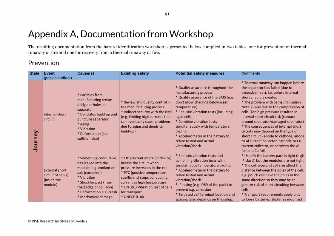
91
© RISE Research Institutes of Sweden
Appendix A, Documentation from Workshop The resulting documentation from the hazard identification workshop is presented below compiled in two tables, one for prevention of thermal runaway or fire and one for recovery from a thermal runaway or fire.
Prevention
State Event Cause(s) Existing safety Potential safety measures Comments (possible effect)
Jour
ney
Internal short circuit
* Particles from manufacturing create bridge or holes in separator * Dendrites build up and puncture separator * Aging * Vibration * Deformation (see collision also)
* Review and quality control in the manufacturing process * Indirect security with the BMS (e.g. limiting high currents that can eventually cause problems due to aging and dendrite build-up)
* Quality assurance throughout the manufacturing process * Quality assurance of the BMS (e.g. don't allow charging below a set temperature) * Realistic vibration tests (including aged cells) * Combine vibration tests simultaneously with temperature cycling * Accelerometer in the battery to relate tested and actual vibration/shock
* Thermal runaway can happen before the separator has failed (due to excessive heat), i.e. before internal short circuit is created * The problem with Samsung (Galaxy Note 7) was due to the compression of cells. Too high pressure resulted in internal short circuit risk (contact around separator/damaged separator) * The consequences of internal short circuits may depend on the type of short circuit - anode to cathode, anode to Al current collector, cathode to Cu current collector, or between the Al foil and Cu foil
External short circuit of cell(s) (inside the module)
* Something conductive has leaked into the module, e.g. coolant or salt (corrosion) * Vibration * Shock/impact (from road edge or collision) * Deformation e.g. crash * Mechanical damage
* CID (current interrupt device) breaks the circuit when pressure increases in the cell * PTC (positive temperature coefficient) stops conducting current at high temperature * UN 38.3 Vibration test of cells for transport * UNECE R100
* Realistic vibration tests and combining vibration tests with simulatneous temperature cycling * Accelerometer in the battery to relate tested and actual vibration/shock * IP rating (e.g. IP69 of the pack) to prevent e.g. corrosion * Targeted cell terminal location and spacing (also depends on the setup,
* Usually the battery pack is tight (high IP class), but the modules are not tight * The cell type and cell size affect the distance between the poles of the cell, e.g. pouch cell have the poles in the same direction so they may be at greater risk of short circuiting between cells * Transport requirements apply only to loose batteries. Batteries mounted
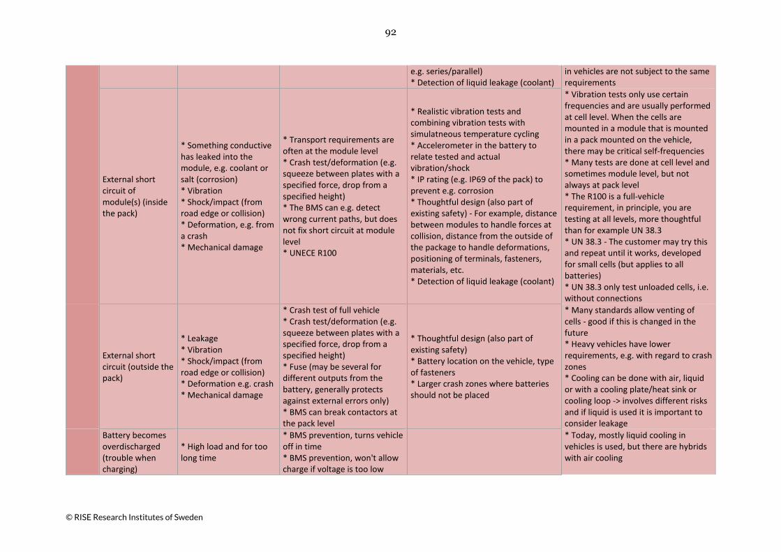
92
© RISE Research Institutes of Sweden
e.g. series/parallel) * Detection of liquid leakage (coolant)
in vehicles are not subject to the same requirements
External short circuit of module(s) (inside the pack)
* Something conductive has leaked into the module, e.g. coolant or salt (corrosion) * Vibration * Shock/impact (from road edge or collision) * Deformation, e.g. from a crash * Mechanical damage
* Transport requirements are often at the module level * Crash test/deformation (e.g. squeeze between plates with a specified force, drop from a specified height) * The BMS can e.g. detect wrong current paths, but does not fix short circuit at module level * UNECE R100
* Realistic vibration tests and combining vibration tests with simulatneous temperature cycling * Accelerometer in the battery to relate tested and actual vibration/shock * IP rating (e.g. IP69 of the pack) to prevent e.g. corrosion * Thoughtful design (also part of existing safety) - For example, distance between modules to handle forces at collision, distance from the outside of the package to handle deformations, positioning of terminals, fasteners, materials, etc. * Detection of liquid leakage (coolant)
* Vibration tests only use certain frequencies and are usually performed at cell level. When the cells are mounted in a module that is mounted in a pack mounted on the vehicle, there may be critical self-frequencies * Many tests are done at cell level and sometimes module level, but not always at pack level * The R100 is a full-vehicle requirement, in principle, you are testing at all levels, more thoughtful than for example UN 38.3 * UN 38.3 - The customer may try this and repeat until it works, developed for small cells (but applies to all batteries) * UN 38.3 only test unloaded cells, i.e. without connections
External short circuit (outside the pack)
* Leakage * Vibration * Shock/impact (from road edge or collision) * Deformation e.g. crash * Mechanical damage
* Crash test of full vehicle * Crash test/deformation (e.g. squeeze between plates with a specified force, drop from a specified height) * Fuse (may be several for different outputs from the battery, generally protects against external errors only) * BMS can break contactors at the pack level
* Thoughtful design (also part of existing safety) * Battery location on the vehicle, type of fasteners * Larger crash zones where batteries should not be placed
* Many standards allow venting of cells - good if this is changed in the future * Heavy vehicles have lower requirements, e.g. with regard to crash zones * Cooling can be done with air, liquid or with a cooling plate/heat sink or cooling loop -> involves different risks and if liquid is used it is important to consider leakage
Battery becomes overdischarged (trouble when charging)
* High load and for too long time
* BMS prevention, turns vehicle off in time * BMS prevention, won't allow charge if voltage is too low
* Today, mostly liquid cooling in vehicles is used, but there are hybrids with air cooling

93
© RISE Research Institutes of Sweden
Battery becomes overcharged
* Brakes or rolls for a long time with a fully charged battery
* BMS prevention, does not allow charging the battery over 100%
Fire outside the battery
* Bad connection * External short circuit * Leakage of fuel (within battery compartment) * Pool fire under battery * Failure of components near battery
* Battery position (high -> very hot from fire, low -> less risk of critical battery heating) * Fuse protects in case of short circuit * BMS indicates isolation errors and will open the contactors
* Battery location (See existing safety) * Separate/protected battery compartment * Use fire resistant materials
* Fire investigations and tests show that low fuel tank/batteries are not always involved in a vehicle fire
BMS or other safety system stops working
* Fire outside the battery (for example)
* Controls and electronics are cooled by cooling system * Contactors on the battery open in case of failure of BMS
State Event Cause(s) Existing safety Potential safety measures Comments (possible effect)
Park
ed
(not
cha
rgin
g)
* Internal short circuit * External short circuit (cell/module/pack)
See above, but not vibration
* See above, but not vibration * The battery is already switched off when the vehicle is switched off (open contactors)
See above, but not vibration
* Some control units are active (with power supply) even when the vehicle is switched off (some parts of the BMS) * Control units are tested for EMC -> very little risk of them being eliminated by interference * Chemical activity (e.g. aging effects) is always present, but e.g. dendrites built up only when charging/discharging
Battery becomes overdischarged (trouble when charging)
* Parked a long time * Greater risk than when driving because BMS does not monitor * Negative balancing discharge other cells if one cell has low voltage
* BMS prevents charging of discharged battery, but if 12/24 V system dies, BMS does not work * The charger must generally contact BMS to start charging
* Critical condition may occur while driving, but with delayed effect, so thermal runaway occurs when vehicles are parked/shut off
Fire outside the battery
See above See above See above

94
© RISE Research Institutes of Sweden
State Event Cause(s) Existing safety Potential safety measures Comments (possible effect)
Cha
rgin
g
Overcharging -> Internal heating (With high SOC at thermal runaway, the scenario becomes worse/faster
Overcharging (e.g. charging too long with high current/voltage)
* BMS does not allow overcharging * Mechanical protection in the cell, e.g. CID, PTC * Charger requires communication between BMS and charging system * Both BMS and charger monitors current and voltage (but usually not every cell)
Quality assurance of the BMS (requirements, standards, etc.)
* BMS is central -> generally tested a lot (but is not better than the programmer) - Many different BMSs that shall work with similar chargers * Many parallel failure events are required for overcharging to happen -> unlikely * E.g. Tesla does not monitor individual cells - uses special/unique balancing of cells
Charging a fully discharged battery -> Internal heating
E.g. Charging of vehicles that have been shut off for a long time
* BMS prevents charging of fully discharged battery, but if 12/24 V system dies, BMS does not work * The charger must generally contact BMS to start charging
* Errors at charging can be caused by, e.g. internal errors reaching a critical level while charging. The battery is highly stressed during charging (especially fast charging) as in prolonged operation at high power
Unbalanced charging
Charging a damaged battery (having loose parts or mechanical damage)
* BMS prevention, shall be discovered -> Replace battery
Fast charging -> heating, wear, aging
Fast charging too often or with too high power
* BMS prevention (e.g. limits the charging effect depending on the SOC level) * Charging station monitors and communicates with BMS * Pantograph - Does not allow charging without good contact (e.g. measures resistance)
* Some cars cannot be fast charged more than twice in a row, then they must be recharged slowly -> e.g. constant driving with several fast charges can build up critical heat over time
Excessive current/power -> builds heat, wear / aging that affects life span
Sensor/measurement error (small errors usually do not have a big risk but can affect life span)
* BMS communicates with the charging station -> e.g. both measure and do not allow conflicting measurement values * External relay attached to the vehicle, i.e. the charging
* There are major differences between electrical installations, e.g. which components are in the vehicle or in the charging station
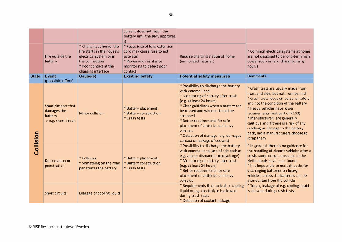
95
© RISE Research Institutes of Sweden
current does not reach the battery until the BMS approves it
Fire outside the battery
* Charging at home, the fire starts in the house's electrical system or in the connection * Poor contact at the charging interface
* Fuses (use of long extension cord may cause fuse to not activate) * Power and resistance monitoring to detect poor contact
Require charging station at home (authorized installer)
* Common electrical systems at home are not designed to be long-term high power sources (e.g. charging many hours)
State Event Cause(s) Existing safety Potential safety measures Comments (possible effect)
Col
lisio
n
Shock/impact that damages the battery -> e.g. short circuit
Minor collision * Battery placement * Battery construction * Crash tests
* Possibility to discharge the battery with external load * Monitoring of battery after crash (e.g. at least 24 hours) * Clear guidelines when a battery can be reused and when it should be scrapped * Better requirements for safe placement of batteries on heavy vehicles * Detection of damage (e.g. damaged contact or leakage of coolant)
* Crash tests are usually made from front and side, but not from behind * Crash tests focus on personal safety and not the condition of the battery * Heavy vehicles have lower requirements (not part of R100) * Manufacturers are generally cautious and if there is a risk of any cracking or damage to the battery pack, most manufacturers choose to scrap them
Deformation or penetration
* Collision * Something on the road penetrates the battery
* Battery placement * Battery construction * Crash tests
* Possibility to discharge the battery with external load (use of salt bath at e.g. vehicle dismantler to discharge) * Monitoring of battery after crash (e.g. at least 24 hours) * Better requirements for safe placement of batteries on heavy vehicles
* In general, there is no guidance for the handling of electric vehicles after a crash. Some documents used in the Netherlands have been found * It is impossible to use salt baths for discharging batteries on heavy vehicles, unless the batteries can be dismounted from the vehicle
Short circuits Leakage of cooling liquid
* Requirements that no leak of cooling liquid or e.g. electrolyte is allowed during crash tests * Detection of coolant leakage
* Today, leakage of e.g. cooling liquid is allowed during crash tests

96
© RISE Research Institutes of Sweden
Fire outside the battery
Leakage of fuel
State Event Cause(s) Existing safety Potential safety measures Comments (possible effect)
Extr
eme
heat
/col
d
* Heating * Short circuit * Aging
Heat or cold outside battery specification in combination with driving or charging
* BMS does not allow charging when it is too cold (or limits charging at low temperatures) * Restrict driving until the battery is sufficiently warm * BMS cools when it's too hot * Most cooling systems are active even if the vehicle is off
* Heating * Short circuit * Aging
Local heat, e.g. solar radiation, asphalt radiation
At least one temperature sensor per module, usually placed in the most critical position
More sensors (a balance between cost/weight/space and safety)
State Event Cause(s) Existing safety Potential safety measures Comments (possible effect)
Wor
ksho
p (in
clud
ing
dism
antli
ng)
Fire or thermal runaway
* Damaged vehicle * Leakage Routines and instructions
* Communicate with battery, read error codes (transport, handling, etc. depending on the status of the battery) * Connect the battery to a pyrotechnic sensor (e.g. if the airbag is released, then the battery will be disconnected, or have its own pyrotechnic fuse in the battery that breaks at a certain g force) * Method of withdrawing energy from the battery (lowering SOC), e.g. external load, salt water or crush
* Workshops can not always communicate with all batteries, special software may be required for a specific manufacturer - important to overcome * Information and instructions are in principle always manufacturer-specific * Certain mechanical errors can not be read * If the read error codes cannot be read due to damage to the BMS, it is good to assume that there may be serious damage to the battery

97
© RISE Research Institutes of Sweden
* Fire or thermal runaway * Electric shock
Improper handling during repair or dismantling
* Tools * Routines and instructions
* Communicate with the battery, read error codes (handling, etc. depending on the status of the battery) * Routines depending on the current charge level (SOC) * Ensure unenergized system, always measure (contactors may be welded due to short circuit) * Method of withdrawing energy from the battery (lowering SOC), e.g. external load, salt water or crush
* If communication with the battery does not work, the battery must be disconnected mechanically (contactors may be welded) * Higher SOC levels always involve greater risks
State Event Cause(s) Existing safety Potential safety measures Comments (possible effect)
Salv
age,
tow
ing
and
jum
psta
rt
Fire or thermal runaway See above
* Routines, instructions and raising the knowledge level for towing companies * Depending on damage, avoid towing through tunnels, on ferries or other critical routes
* Shortly after a crash/incident, the risk of something happening during salvage/towing may be greater with electric vehicles than with other vehicles
The vehicle starts to drive Routines and instructions
Jumpstart
The 12/24 V battery is dead -> The BMS does not work -> The vehicle can not start
Don't jumpstart or charge an electric vehicle in this situation
* If the 12/24 V battery is dead, the BMS does not work and it is not possible to know what's wrong -> must be investigated (E.g. what is the status of the traction battery? Or will the 12/24 V battery be discharged again soon?)

98
© RISE Research Institutes of Sweden
Recovery
System Desired functions
Affecting conditions
Existing safety State Challenges Potential safety measures Comments
Ther
mal
runa
way
* Low heat development
* Battery chemistry
High cell quality All The amount of
fluorine Minimize fluorine-based electrolyte (LiPF6)
* Intensive research is underway with many different alternative electrolytes, battery chemistry, etc.
* Low generation of combustible and toxic gases
* Type of electrolyte (and the amount of fluorine)
All Combustible electrolyte Ongoing research
* During storage, a low SOC (~ 35 %) is used. (Many batteries/high energy sources are stored on top of each other)
* Cell type - pouch, etc. * SOC
All SOC more than 50 %
Limit SOC level (requirements are for transport of loose batteries but not for transport of vehicles)
* Long storage with low charge can cause problems. E.g. long transport requires a good charge to ensure that SOC is OK on delivery
* Initial cause (abuse condition)
* Transport requirements for batteries - 30 % SOC (air) means low risk of spreading in case of malfunction (builds too little heat) No difference in requirements with regard to new/old batteries * Thermal runaway at charging -> greater risk for high SOC
System Desired functions
Affecting conditions
Existing safety State Challenges Potential safety measures Comments
Cel
l ->
Mod
ule
* No spread to nearby cells
* Cell type (cylindrical, prismatic, pouch)
* Safety valve that opens at high pressure
All
Direction of safety valve/ventilation (different between different cell types)
* Construction of the cells - avoid ventilation directed against adjacent cells * Pouch cell - awareness of the weakest point
* A pouch cell can ventilate in most directions, but usually it is a weak welding at the top or bottom * When a cell reaches thermal runaway, there is a risk that other cells will be close to their limit -> fast progress (dependent on type of failure event)
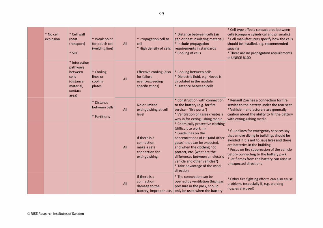
99
© RISE Research Institutes of Sweden
* No cell explosion
* Cell wall (heat transport) * SOC
* Weak point for pouch cell (welding line)
All * Propagation cell to cell * High density of cells
* Distance between cells (air gap or heat insulating material) * Include propagation requirements in standards * Cooling of cells
* Cell type affects contact area between cells (compare cylindrical and prismatic) * Cell manufacturers specify how the cells should be installed, e.g. recommended spacing * There are no propagation requirements in UNECE R100
* Interaction pathways between cells (distance, material, contact area)
* Cooling lines or cooling plates
All
Effective cooling (also for failure event/exceeding specifications)
* Cooling between cells * Dielectric fluid, e.g. Novec is circulated in the module * Distance between cells
* Distance between cells * Partitions
All No or limited extinguishing at cell level
* Construction with connection to the battery (e.g. for fire service - "fire ports") * Ventilation of gases creates a way in for extinguishing media
* Renault Zoe has a connection for fire service to the battery under the rear seat * Vehicle manufacturers are generally caution about the ability to fill the battery with extinguishing media
All
If there is a connection: make a safe connection for extinguishing
* Chemically protective clothing (difficult to work in) * Guidelines on the concentrations of HF (and other gases) that can be expected, and when the clothing not protect, etc. (what are the differences between an electric vehicle and other vehicles?) * Take advantage of the wind direction
* Guidelines for emergency services say that smoke diving in buildings should be avoided if it is not to save lives and there are batteries in the building * Focus on fire suppression of the vehicle before connecting to the battery pack * Jet flames from the battery can arise in unexpected directions
All
If there is a connection: damage to the battery, improper use,
* The connection can be opened by ventilation (high gas pressure in the pack, should only be used when the battery
* Other fire fighting efforts can also cause problems (especially if, e.g. piercing nozzles are used)
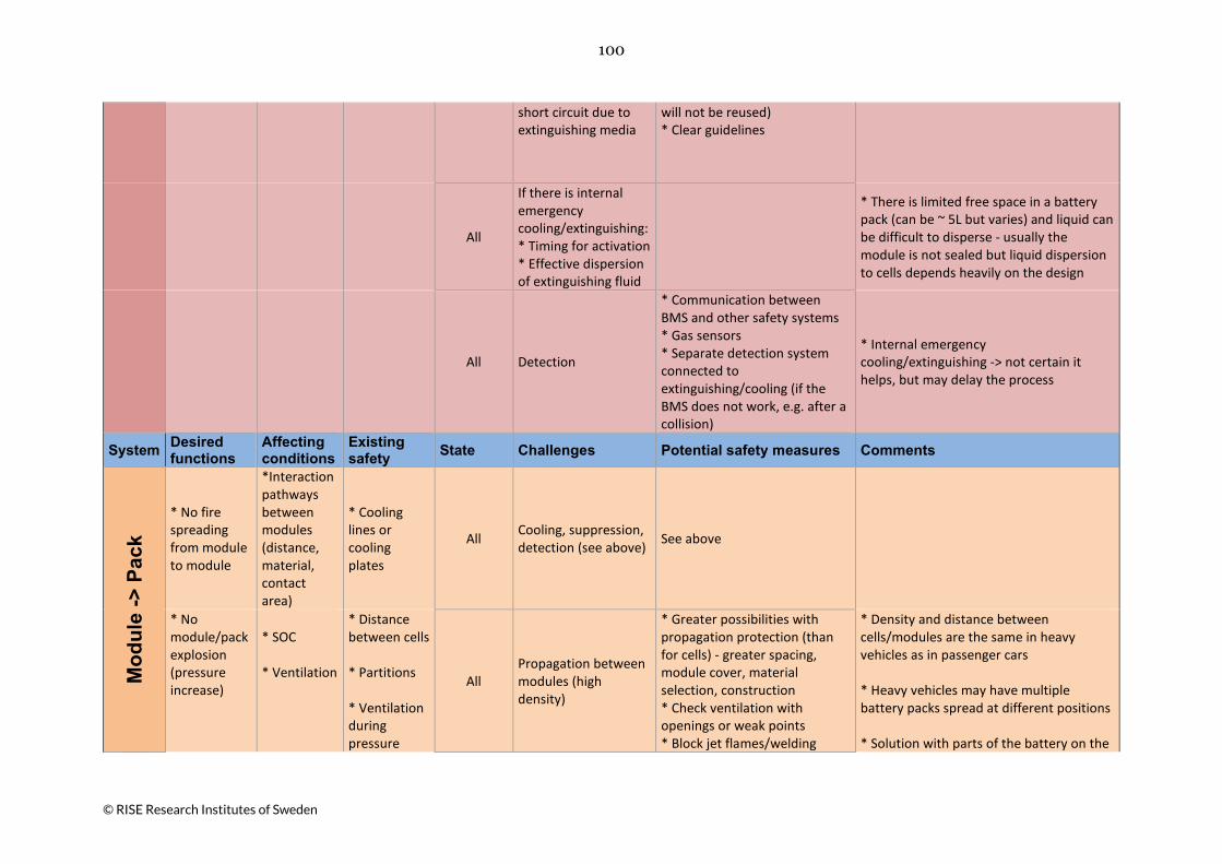
100
© RISE Research Institutes of Sweden
short circuit due to extinguishing media
will not be reused) * Clear guidelines
All
If there is internal emergency cooling/extinguishing: * Timing for activation * Effective dispersion of extinguishing fluid
* There is limited free space in a battery pack (can be ~ 5L but varies) and liquid can be difficult to disperse - usually the module is not sealed but liquid dispersion to cells depends heavily on the design
All Detection
* Communication between BMS and other safety systems * Gas sensors * Separate detection system connected to extinguishing/cooling (if the BMS does not work, e.g. after a collision)
* Internal emergency cooling/extinguishing -> not certain it helps, but may delay the process
System Desired functions
Affecting conditions
Existing safety State Challenges Potential safety measures Comments
Mod
ule
-> P
ack
* No fire spreading from module to module
*Interaction pathways between modules (distance, material, contact area)
* Cooling lines or cooling plates
All Cooling, suppression, detection (see above) See above
* No module/pack explosion (pressure increase)
* SOC * Ventilation
* Distance between cells * Partitions * Ventilation during pressure
All Propagation between modules (high density)
* Greater possibilities with propagation protection (than for cells) - greater spacing, module cover, material selection, construction * Check ventilation with openings or weak points * Block jet flames/welding
* Density and distance between cells/modules are the same in heavy vehicles as in passenger cars * Heavy vehicles may have multiple battery packs spread at different positions * Solution with parts of the battery on the
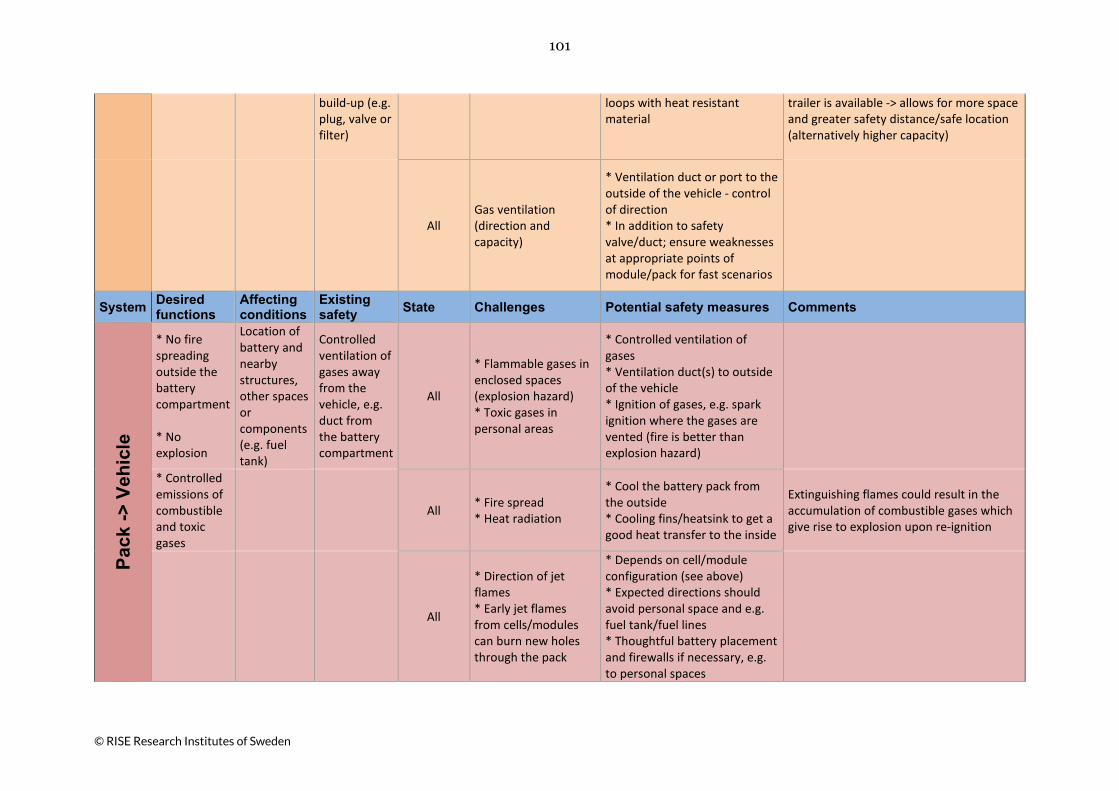
101
© RISE Research Institutes of Sweden
build-up (e.g. plug, valve or filter)
loops with heat resistant material
trailer is available -> allows for more space and greater safety distance/safe location (alternatively higher capacity)
All Gas ventilation (direction and capacity)
* Ventilation duct or port to the outside of the vehicle - control of direction * In addition to safety valve/duct; ensure weaknesses at appropriate points of module/pack for fast scenarios
System Desired functions
Affecting conditions
Existing safety State Challenges Potential safety measures Comments
Pack
-> V
ehic
le
* No fire spreading outside the battery compartment * No explosion
Location of battery and nearby structures, other spaces or components (e.g. fuel tank)
Controlled ventilation of gases away from the vehicle, e.g. duct from the battery compartment
All
* Flammable gases in enclosed spaces (explosion hazard) * Toxic gases in personal areas
* Controlled ventilation of gases * Ventilation duct(s) to outside of the vehicle * Ignition of gases, e.g. spark ignition where the gases are vented (fire is better than explosion hazard)
* Controlled emissions of combustible and toxic gases
All * Fire spread * Heat radiation
* Cool the battery pack from the outside * Cooling fins/heatsink to get a good heat transfer to the inside
Extinguishing flames could result in the accumulation of combustible gases which give rise to explosion upon re-ignition
All
* Direction of jet flames * Early jet flames from cells/modules can burn new holes through the pack
* Depends on cell/module configuration (see above) * Expected directions should avoid personal space and e.g. fuel tank/fuel lines * Thoughtful battery placement and firewalls if necessary, e.g. to personal spaces

102
© RISE Research Institutes of Sweden
System Desired functions
Affecting conditions
Existing safety State Challenges Potential safety measures Comments
Vehi
cle
-> E
nviro
nmen
t * Vehicle fire should have a limited effect on surroundings * Fire extinguishing
* Localization * Ambient environment during collision and towing (e.g. tunnel, bridge, ferry) * Closed spaces (e.g. garage, building, workshop) * Transport of road vehicles on e.g. ferry and train
*Collision *Workshop *Salvage/ towing
Fire spreading from crashed vehicle
* Safety distance (at least 6 m), larger distance to buildings etc. * Separate location with low risk of fire spread * Protected location, e.g. container without roof, concrete wall or other fire resistant barrier * Handle damaged batteries/vehicles outdoors (but temperature and humidity can cause problems) Or put the vehicle back outdoors when not handled (e.g. overnight) * Important with risk analysis - how serious is the damage?, what is the status of batteries? etc. * Method for extracting energy from the battery, such as external load, salt water or crushing
* An open container with flammable material has recommended safety clearance of 6 m * Cabinets with flammable goods (outdoor) have recommended safety distance of 15 m, e.g. Tesla recommends 15 m if the battery is damaged. A recommendation from the Netherlands says 10 m for 48 hours * If the vehicle burns, it is generally not transported to the workshop but directly to the scrap yard * What actions should be taken before starting repair/dismantling of the vehicle?
* Ambient flammable materials, e.g. industrial areas
Workshop Workshop is underground or part of a larger building
See above
*Collision *Workshop *Salvage/ towing
Greater risk immediately and short after collision
* Time aspect - delayed handling * Depending on location, delay salvage or handling at workshop/dismantling
* There is at least one case when it took 3 weeks before ignition, but it usually happens within 24 hours

103
© RISE Research Institutes of Sweden
Workshop Flammable material at workshop/dismantling
Safety distance (see above)
System Desired functions
Affecting conditions
Existing safety State Challenges Potential safety measures Comments
Exte
rnal
fire
* Fire extinguishing (e.g. fuel leakage, wheelhouse fire, electrical component etc.)
All
To know where the battery/ batteries are located (for emergency services)
* Greatest focus on extinguishing the fire - when the battery is involved, the fire is usually already large (the entire vehicle)
* Does not involve the battery in the fire
System Desired functions
Affecting conditions
Existing safety State Challenges Potential safety measures Comments
Exte
rnal
fire
-> E
nviro
nmen
t/ B
atte
ry p
ack
* Limited fire spread within the vehicle and to environment
All
* Assessment of battery after minor fire in the vehicle Can the battery be reused?
* SOH - State of health of the battery (focuses on performance, not the risk of malfunction) * Analysis of SOH (e.g. failure trends/ any major change) may indicate increased risk - decision support for battery reuse * Improved predictive models (incl. AI) * Temperature data can be saved and the temperature impact can be checked retrospectively (BMS)
* Degradation of the battery is not linear, can go fast at the end * Workshop makes assessment, but insurance companies decide if the vehicle is to be repaired or scrapped

104
© RISE Research Institutes of Sweden
Appendix B, Participants of Workshop The participants of the hazard identification workshop are presented below.
Participants Organisation Profession/Competence and Role
Ola Willstrand RISE Expert in vehicle fire safety and moderator
Max Rosengren RISE Senior expert in electrical safety and heavy vehicles
Roeland Bisschop RISE Expert in vehicle fire safety and scribe
Petra Andersson RISE Senior research scientist and expert in li-ion batteries
Gabriel Oltean Scania CV Development engineer, Battery cell testing
Stefan Fasth Volvo Bus Electromobility Coordinator, Production
Bo Ericsson SFVF (Swedish Association of Vehicle Workshops)
CEO
Anders Gulliksson Dafo Vehicle Fire Protection Senior quality executive (Fire suppression systems)
Gustav Stigsohn Fogmaker International Product manager (Fire suppression systems)
Conny Lindstedt Fogmaker International Project engineer (Fire suppression systems)

© RISE Research Institutes of Sweden
Through our international collaboration programmes with academia, industry, and the public
sector, we ensure the competitiveness of the Swedish business community on an international
level and contribute to a sustainable society. Our 2,200 employees support and promote all
manner of innovative processes, and our roughly 100 testbeds and demonstration facilities are
instrumental in developing the future-proofing of products, technologies, and services. RISE
Research Institutes of Sweden is fully owned by the Swedish state.
I internationell samverkan med akademi, näringsliv och offentlig sektor bidrar vi till ett
konkurrenskraftigt näringsliv och ett hållbart samhälle. RISE 2 200 medarbetare driver och stöder
alla typer av innovationsprocesser. Vi erbjuder ett 100-tal test- och demonstrationsmiljöer för
framtidssäkra produkter, tekniker och tjänster. RISE Research Institutes of Sweden ägs av
svenska staten.
RISE Research Institutes of Sweden AB
Box 857, SE-501 15 BORÅS, Sweden
Telephone: +46 10 516 50 00
E-mail: [email protected], Internet: www.ri.se
Fire Research
RISE Report 2019:50
ISBN: 978-91-88907-78-3