Embed Size (px)
Citation preview

SSP 30599 REVISION A
Safety Review Process
International Space Station Alpha Program
Revision A
January 11, 1995
National Aeronautics and Space Administration International Space Station Alpha Program Johnson Space Center Houston, Texas Contract No. NAS15–10000
SSP 30599 Revision A
REVISION AND HISTORY PAGE
REV. DESCRIPTION PUB. DATE
–
A
BASELINE ISSUE (REFERENCE SSCBD BB003229B EFF.)
Revision A (SSDBD 000085 EFF. 05–05–95) (No cost change – ECP 85)
10–93
6–15–95
SSP 30599 Revision A
PREFACE
The contents of this document are intended to be consistent with the tasks and products to be prepared by Program participants. SSP 30599 shall be implemented on all new International Space Station Alpha (ISSA) contractual and internal activities and shall be included in any existing contracts through contract changes. This document is under the control of the Space Station Control Board and any changes or revisions will be approved by the Program Manager or statement to indicate the delegated authority (i.e., Space Station Analysis and Integration Team [SSAIT], Vehicle Analysis and Integration Team [VAIT]).
Program Manager, Date International Space Station Alpha
i
SSP 30599 Revision A
INTERNATIONAL SPACE STATION ALPHA PROGRAM
SAFETY REVIEW PROCESS FOR INTERNATIONAL SPACE STATION ALPHA PROGRAM
JANUARY 11, 1994
CONCURRENCE
PREPARED BY: Marla Duhon OE PRINT NAME ORGN
/s/ Marla Duhon 1/13/95 SIGNATURE DATE
CHECKED BY: Kevin A. Klein OE PRINT NAME ORGN
/s/ Kevin A. Klein 1/13/95 SIGNATURE DATE
SUPERVISED BY (NASA): PRINT NAME
J. Harold Taylor OE ORGN
/s/ J. Harold Taylor 1/13/95 SIGNATURE DATE
DQA: PRINT NAME Jeff Prince 2–6640
ORGN
SIGNATURE
Jeff Prince /s/ 95/02/03 DATE
ii
SSP 30599 Revision A
INTERNATIONAL SPACE STATION ALPHA (ISSA) PROGRAM OFFICE
SAFETY REVIEW PROCESS FOR ISSA PROGRAM
LIST OF CHANGES
JANUARY 11, 1995
All changes to paragraphs, tables, and figures in this document are shown below:
SSCBD ENTRY DATE CHANGE PARAGRAPHS
ENTIRE DOCUMENT REVISED
iii
SSP 30599 Revision A
TABLE OF CONTENTS
PARAGRAPH PAGE
1.0 INTRODUCTION . . . . . . . . . . . . . . . . . . . . . . . . . . . . . . . . . . . . . . . . . . . . . . . . . . . . . . . . . . . . . . . . . . . 1 – 1
1.1 PURPOSE . . . . . . . . . . . . . . . . . . . . . . . . . . . . . . . . . . . . . . . . . . . . . . . . . . . . . . . . . . . . . . . . . . . . . . . . 1 – 1
1.2 SCOPE . . . . . . . . . . . . . . . . . . . . . . . . . . . . . . . . . . . . . . . . . . . . . . . . . . . . . . . . . . . . . . . . . . . . . . . . . . . 1 – 1
1.3 DELEGATION OF AUTHORITY . . . . . . . . . . . . . . . . . . . . . . . . . . . . . . . . . . . . . . . . . . . . . . . . . . . . . . 1 – 2
1.4 WAIVER/DEVIATIONS . . . . . . . . . . . . . . . . . . . . . . . . . . . . . . . . . . . . . . . . . . . . . . . . . . . . . . . . . . . . . . 1 – 2
2.0 APPLICABLE DOCUMENTS . . . . . . . . . . . . . . . . . . . . . . . . . . . . . . . . . . . . . . . . . . . . . . . . . . . . . . . . . 2 – 1
2.1 REFERENCE DOCUMENTS . . . . . . . . . . . . . . . . . . . . . . . . . . . . . . . . . . . . . . . . . . . . . . . . . . . . . . . . 2 – 1
3.0 SAFETY RESPONSIBILITIES . . . . . . . . . . . . . . . . . . . . . . . . . . . . . . . . . . . . . . . . . . . . . . . . . . . . . . . . 3 – 1
3.1 NASA . . . . . . . . . . . . . . . . . . . . . . . . . . . . . . . . . . . . . . . . . . . . . . . . . . . . . . . . . . . . . . . . . . . . . . . . . . . . . 3 – 1
3.2 SAFETY RESPONSIBILITIES OF INTERNATIONAL PARTNERS. . . . . . . . . . . . . . . . . . . . . . . . . 3 – 1
4.0 ISSA SAFETY REVIEW PROCESS . . . . . . . . . . . . . . . . . . . . . . . . . . . . . . . . . . . . . . . . . . . . . . . . . . . 4 – 1
4.1 SAFETY ANALYSES AND DELIVERABLES . . . . . . . . . . . . . . . . . . . . . . . . . . . . . . . . . . . . . . . . . . . 4 – 1
4.2 SAFETY REVIEW OBJECTIVES . . . . . . . . . . . . . . . . . . . . . . . . . . . . . . . . . . . . . . . . . . . . . . . . . . . . . 4 – 1
4.3 ISSA SAFETY REVIEW PROCESS . . . . . . . . . . . . . . . . . . . . . . . . . . . . . . . . . . . . . . . . . . . . . . . . . . . 4 – 2
4.3.1 INLINE SAFETY REVIEWS. . . . . . . . . . . . . . . . . . . . . . . . . . . . . . . . . . . . . . . . . . . . . . . . . . . . . . . . . . 4 – 2
4.3.2 FORMAL SAFETY REVIEWS FOR US ELEMENTS . . . . . . . . . . . . . . . . . . . . . . . . . . . . . . . . . . . . 4 – 2
4.3.3 PHASE SAFETY REVIEWS FOR IP SEGMENTS/ELEMENTS . . . . . . . . . . . . . . . . . . . . . . . . . . . 4 – 2
4.3.4 SAFETY STATUS . . . . . . . . . . . . . . . . . . . . . . . . . . . . . . . . . . . . . . . . . . . . . . . . . . . . . . . . . . . . . . . . . . 4 – 3
4.4 SAFETY REVIEW MEETINGS AND AGENDA . . . . . . . . . . . . . . . . . . . . . . . . . . . . . . . . . . . . . . . . . 4 – 6
4.5 HAZARD REPORT DISPOSITION . . . . . . . . . . . . . . . . . . . . . . . . . . . . . . . . . . . . . . . . . . . . . . . . . . . . 4 – 6
4.6 PROGRAM HAZARD REPORT ACCEPTANCE . . . . . . . . . . . . . . . . . . . . . . . . . . . . . . . . . . . . . . . . 4 – 6
4.7 CERTIFICATE OF FLIGHT READINESS PROCESS . . . . . . . . . . . . . . . . . . . . . . . . . . . . . . . . . . . . 4 – 7
4.8 SAFETY REVIEW DATA SUBMITTALS . . . . . . . . . . . . . . . . . . . . . . . . . . . . . . . . . . . . . . . . . . . . . . . . 4 – 7
5.0 PHASE SAFETY REVIEWS . . . . . . . . . . . . . . . . . . . . . . . . . . . . . . . . . . . . . . . . . . . . . . . . . . . . . . . . . 5 – 1
5.1 PHASE I SAFETY REVIEW . . . . . . . . . . . . . . . . . . . . . . . . . . . . . . . . . . . . . . . . . . . . . . . . . . . . . . . . . . 5 – 1
5.1.1 PHASE I DATA REQUIREMENTS . . . . . . . . . . . . . . . . . . . . . . . . . . . . . . . . . . . . . . . . . . . . . . . . . . . . 5 – 1
5.1.2 PHASE I HAZARD REPORTS . . . . . . . . . . . . . . . . . . . . . . . . . . . . . . . . . . . . . . . . . . . . . . . . . . . . . . . 5 – 2
5.1.3 SUPPORT DATA – PHASE I HRS. . . . . . . . . . . . . . . . . . . . . . . . . . . . . . . . . . . . . . . . . . . . . . . . . . . . 5 – 2
5.2 PHASE II SAFETY REVIEW . . . . . . . . . . . . . . . . . . . . . . . . . . . . . . . . . . . . . . . . . . . . . . . . . . . . . . . . . 5 – 3
5.2.1 PHASE II DATA REQUIREMENTS . . . . . . . . . . . . . . . . . . . . . . . . . . . . . . . . . . . . . . . . . . . . . . . . . . . . 5 – 3
5.2.2 PHASE II HAZARD REPORTS . . . . . . . . . . . . . . . . . . . . . . . . . . . . . . . . . . . . . . . . . . . . . . . . . . . . . . . 5 – 4
5.2.3 SUPPORT DATA – PHASE II HRS. . . . . . . . . . . . . . . . . . . . . . . . . . . . . . . . . . . . . . . . . . . . . . . . . . . . 5 – 4
5.3 PHASE III SAFETY REVIEW . . . . . . . . . . . . . . . . . . . . . . . . . . . . . . . . . . . . . . . . . . . . . . . . . . . . . . . . 5 – 5
5.3.1 PHASE III DATA REQUIREMENTS . . . . . . . . . . . . . . . . . . . . . . . . . . . . . . . . . . . . . . . . . . . . . . . . . . . 5 – 5
5.3.2 PHASE III HAZARD REPORTS . . . . . . . . . . . . . . . . . . . . . . . . . . . . . . . . . . . . . . . . . . . . . . . . . . . . . . 5 – 6
5.3.3 SUPPORT DATA – PHASE III HRS . . . . . . . . . . . . . . . . . . . . . . . . . . . . . . . . . . . . . . . . . . . . . . . . . . . 5 – 7
5.1.2 PHASE I HAZARD REPORTS . . . . . . . . . . . . . . . . . . . . . . . . . . . . . . . . . . . . . . . . . . . . . . . . . . . . . . . 5 – 7
5.4 POST PHASE III SAFETY ACTIVITY . . . . . . . . . . . . . . . . . . . . . . . . . . . . . . . . . . . . . . . . . . . . . . . . . 5 – 8
iv
SSP 30599 Revision A
6.0 NONCOMPLIANCE WITH SPACE STATION REQUIREMENTS . . . . . . . . . . . . . . . . . . . . . . . . . . 6 – 1
7.0 SIMILAR AND REFLOWN EQUIPMENT . . . . . . . . . . . . . . . . . . . . . . . . . . . . . . . . . . . . . . . . . . . . . . . 7 – 1
APPENDICES
A ABBREVIATIONS AND ACRONYMS . . . . . . . . . . . . . . . . . . . . . . . . . . . . . . . . . . . . . . . . . . . . . . . . . A – 1
B INSTRUCTIONS FOR ISSA HAZARD REPORT FORM . . . . . . . . . . . . . . . . . . . . . . . . . . . . . . . . . B – 1
C INSTRUCTIONS FOR ISSA SAFETY VERIFICATION TRACKING LOG . . . . . . . . . . . . . . . . . . . C –1
FIGURES
4.3.2–1 ISSA PROGRAM SAFETY REVIEW PROCESS . . . . . . . . . . . . . . . . . . . . . . . . . . . . . . . . . . . . . . . . 4 – 4
5.1.1–1 IONIZING RADIATION DATA SHEET, JSC FORM 44 (PAGE 1 OF 2) . . . . . . . . . . . . . . . . . . . . . . 5 – 9
B.1-1 HAZARD REPORT LEGEND (PAGE 1 OF 6) . . . . . . . . . . . . . . . . . . . . . . . . . . . . . . . . . . . . . . . . . . . B – 3
C.1–1 SAFETY VERIFICATION TRACKING LOG . . . . . . . . . . . . . . . . . . . . . . . . . . . . . . . . . . . . . . . . . . . . C–3
TABLES
4.3.3–1 SUMMARY OF SAFETY REVIEW PROCESS . . . . . . . . . . . . . . . . . . . . . . . . . . . . . . . . . . . . . . . . . . 4 – 5
B.1-1 SEVERITY CATEGORY . . . . . . . . . . . . . . . . . . . . . . . . . . . . . . . . . . . . . . . . . . . . . . . . . . . . . . . . . . . . . B – 13
B.1-2 LIKELIHOOD OF OCCURRENCE . . . . . . . . . . . . . . . . . . . . . . . . . . . . . . . . . . . . . . . . . . . . . . . . . . . . B – 14
v

SSP 30599 Revision A
1.0 INTRODUCTION
The International Space Station Alpha Program (ISSAP) has developed a Safety Review Process to execute its responsibilities for the overall integrated safety of the ISSA. That process is defined in herein. This process will assess the design of the ISSA element hardware to the safety requirements established in SSP 50021, Safety Requirements Document.
The Safety Review Process is defined for: ISSA elements (flight and ground), and ISSA support equipment. This process includes an inline safety review of United States (US) elements and a phase safety review approach for International Partner (IP) elements. The requirements of phase safety reviews for IP elements covering the all mission phases of ISSA equipment are encompassed within this document and are intended to be consistent with the tasks and products to be prepared by the National Aeronautics and Space Administration (NASA) and IPs as specified in the appropriate Bilateral Safety and Mission Assurance processes document. SSP 30309, Safety Analysis Requirements, or its IP equivalent, provides the methodology for preparation, maintenance, and reporting requirements of safety analyses in support of the safety reviews.
1.1 PURPOSE
The purpose of SSP 30599 is to define the safety review process for ISSA elements (flight and ground), support equipment, and integration of experiment racks into modules. The safety review process for ISSA payload experiments (flight and ground) including integration of experiments into the racks is defined in National Space Transportation System (NSTS) 13830, Implementation Procedure for NSTS Payloads System Safety Requirements. Integration of ISSA element review responsibilities and requirements into a single process ensures effective identification and assessment of safety compliance involving ISSA equipment, and minimizes any overlap that could exit if there were different review processes for the various mission phases of ISSA hardware elements.
1.2 SCOPE
This document defines the process that NASA has implemented to assess compliance with the ISSA safety requirements in SSP 50021. The ISSA safety reviews are conducted to review and assess the safety hazards for all mission phases related to the design, operations, and functional capabilities of ISSA elements and support equipment, and the integration of all ISSA elements.
This document describes: the responsibilities of the organizations involved in the safety review process in paragraph 3.0; the ISSA safety review process in paragraph 4.0; the procedures and data requirements for each IP safety reviews in paragraph 5.0; the process and documentation of requirements noncompliances in paragraph 6.0; and special review procedures for similar and reflown equipment in paragraph 7.0.
The safety reviews of ISSA experiment payloads are not included within the scope of the process defined by this document. Details regarding the safety review process imposed on ISSA
1 – 1

SSP 30599 Revision A
payloads and the on–orbit increment payload complement will be reviewed by the Payload Safety Review Panel (PSRP) in accordance with NSTS 13830 for assessing compliance with NSTS 1700.7.
1.3 DELEGATION OF AUTHORITY
This document is the responsibility of the ISSA Program Office. This document is subject to change control.
1.4 WAIVER/DEVIATIONS
Any request for waiver or deviation from the requirements of this document shall be made to the ISSA in accordance with Configuration Management Requirements.
1 – 2

SSP 30599 Revision A
2.0 APPLICABLE DOCUMENTS
The following documents are applicable as specified herein. These include specifications, models, standards, guidelines, handbooks, and other special publications. An International Partner may substitute for a cited ”applicable” document if the substitution has been reviewed and agreed that it meets or exceeds the requirements of the cited document.
DOCUMENT NO. TITLE KHB 1860.1A Kennedy Space Center (KSC) December 20, 1988 Ionizing Radiation Protection Program
References ReferencesParagraphs 5.2.2, 5.3.2 and Appendix B
KHB 1860.2 KSC Non–Ionizing Radiation April 20, 1981 Protection Program
References ReferencesParagraphs 5.2.2, 5.3.2 and Appendix B
SSP TBD ISSA Certification of Flight Readiness Process SSP 30233 Space Station Requirements for Materials and Process SSP 30309 Safety Analysis and Risk Assessment Requirements SSP 30558 Fracture Control Requirements for Space Station SSP 30559 Structural Design and Verification Requirements SSP 30560 Glass, Window, and Ceramic Structural Design and
Verification Requirements SSP 30666, Volume 1 Program Master Verification Plan: Approach and Process SSP 50004 Support Equipment Design Requirements SSP 50021 Safety Policy and Requirements
2.1 REFERENCE DOCUMENTS NSTS 1700.7B Safety Policy and Requirements January 13, 1989 for Payloads Using the Space Transportation System
NSTS 13830B Implementation Procedure for November 14, 1989 NSTS Payloads System Safety Requirements
2–1
SSP 30599 Revision A
3.0 SAFETY RESPONSIBILITIES
3.1 NASA
NASA, as an Partner in the ISSA Program, is responsible for the overall integrated safety of the ISSA and will be required to provide the overall certification that the ISSA elements and payloads are safe. It is also the responsibility of NASA to establish the overall safety requirements of the program. To successfully implement NASA’s overall safety responsibility, the safety requirements of SSP 50021, Safety Policy and Requirements, and SSP 50004, Support Equipment Design Requirements, have been developed. NASA will assure compliance with these overall safety requirements within the ISSA Program by the close coordination of a well structured safety review process with the formal ISSA design review process. The Flight Safety Review Panel (SRP) is responsible for assessing the ISSA elements against the requirements in SSP 50021. The Ground Safety Review Panel (GSRP) is responsible for assessing ISSA Ground Support Equipment (GSE) used at Kennedy Space Center (KSC) and KSC launch and landing site operations against the requirements of SSP 50004. ISSA equipment which returns on the Orbiter is reviewed by the Ground and Flight Safety Review Panels for on–orbit operations, reentry, landing and post landing operations. This review may be part of the stage review if the return cargo has been adequately defined. For the US elements this process is an inline process with formal safety reviews concurrent with major program milestone reviews.
NASA’s prime contractor safety responsibilities are as defined in the Prime Contractor’s Statement of Work (SOW). For IP elements this process includes a phased safety review process defined in section 5.0.
3.2 SAFETY RESPONSIBILITIES OF INTERNATIONAL PARTNERS
It is the responsibility of the IPs to support NASA’s overall safety reviews and to certify that all applicable safety requirements have been met with respect to IP elements and payloads. The applicable overall safety requirements for IP elements are contained in SSP 50021, which are allocated and flowed down into the IP segment specifications.
3 – 1

SSP 30599 Revision A
4.0 ISSA SAFETY REVIEW PROCESS
4.1 SAFETY ANALYSES AND DELIVERABLES
The safety review process was developed to evaluate and assess the results of the US and IP safety analyses conducted by developers, providers, and operators of ISSA element hardware and software. Performance of hazard analyses provides a means to systematically and objectively identify hazards, as well as their causes and controls. ISSA safety analyses include as a minimum traditional hazard analyses in accordance with SSP 30309 (i.e., preliminary hazard analysis, system hazard analyses, operation and support hazard analysis, software safety analysis, and integrated hazard analyses). Safety analyses are performed on a flight by flight, stage by stage basis. Hazards identified through the Safety analysis process are documented on a Hazard Report (HR) as defined by appendix B.
The safety assessment of all ISSA systems and operations are provided to the ISSA Flight and Ground Safety Review Panels by safety deliverables including HRs and other applicable data. These deliverables are submitted in accordance with the applicable contractual data requirement defined in contract SOW, or Bilateral Data Exchange Agreement for International Partners.
a. The ISSA Prime Contractor’s safety deliverable for integrated hazard analysis will address the launch package, on orbit assembly, stage, and ground assessments.
b. The Product Groups for the ISSA Prime Contractor provide the safety deliverables for their hardware and software, including support equipment and ground processing, in the form of flight and ground Hazard Assessment Reports (HARs) which include system descriptive data, hazard reports, and supporting data.
c. The safety deliverables from IPs will address their Element hardware (flight and ground) including support equipment, and ground processing per the applicable Bilateral Data Exchange Agreements.
4.2 SAFETY REVIEW OBJECTIVES
The objective of the ISSA safety program is to achieve the maximum degree of safety consistent with ISSA objectives and operational requirements while complying with NASA Safety policy. The goal of the safety reviews in this process are to eliminate hazards through design modifications and to assure that all hazards and their causes inherent in the design have been identified and evaluated. The ISSA Flight and Ground Safety Review Panels will assess safety for all phases of the ISSA program (i.e., from design and development, through ground processing and launch [only applicable for Shuttle launches from KSC], to on–orbit assembly and operation, and to disposal or return of hardware from orbit).
The purpose of safety review meetings is for the flight and ground safety review panels to assess the results of safety assessments performed by US or International Partner(s). The results are reported at the program design reviews.
4 – 1

SSP 30599 Revision A
4.3 ISSA SAFETY REVIEW PROCESS
The safety review process is an incremental process that will focus on: assuring that all hazards and hazard causes inherent in the design and operations have been identified; evaluating the means employed to control the risk; and assessing the methods identified to verify all hazard controls. The process is implemented by the conduct of safety reviews with the developers, providers and operators of the ISSA elements.
4.3.1 INLINE SAFETY REVIEWS
For US elements, an inline safety review process has been developed for review of hazard reports from the ISSA Prime Contractor and the Prime Contractor’s Product Groups. This inline process will culminate in a formal safety reviews in conjunction with major program milestone reviews. The inline safety process is a concurrent engineering approach which facilitates the implementation of safety design changes to control and eliminate hazards in a timely manner. The data submittals for the inline process will be in accordance with the applicable contractual requirements of the SOW and are submitted at least ten days prior to the inline review.
Prior to the inline safety reviews with the ISSA Flight Safety Review Panel or Ground Safety Review Panel, Launch Package/Stage (LP/S) Integrated Product Teams (IPTs)/Analysis and Integration Team (AIT) and safety IPT/AITs will review the appropriate safety assessment results to assure technical content and to identify issues which need to be resolved prior to delivery and presentation of the data to the safety panels. The safety review panels are available to assist the IPT/AITs in resolving issues and in providing clarification and interpretation of safety requirements necessary for issue resolution.
4.3.2 FORMAL SAFETY REVIEWS FOR US ELEMENTS
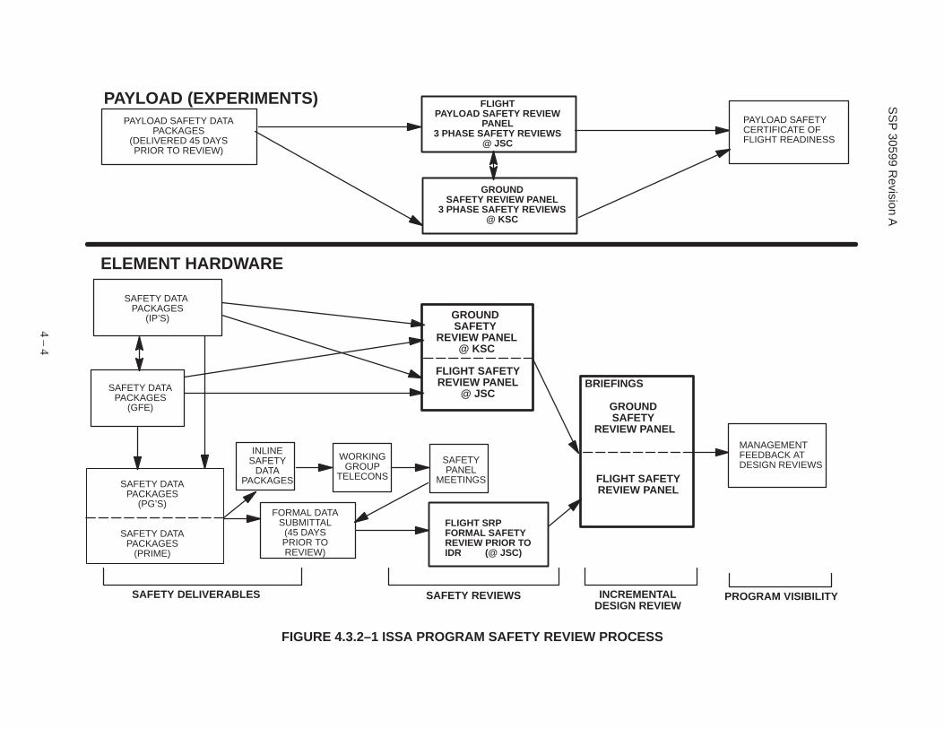
The formal safety reviews for US elements are the forums during which the safety data developed and assessed during the inline process are compiled to form a complete safety analyses for a launch package or stage. The disposition of LP/S hazard reports by the safety review panels will be in accordance with paragraph 4.5. During these reviews the hazard reports that are acceptable will be signed. The schedule of formal safety reviews for the US elements is based upon the schedule of the program major milestone reviews. Figure 4.3.2–1, ISSA Program Safety Review Process, defines the general ISSA Safety Review Process flow. Safety reviews are scheduled for each stage on the Engineering Master Schedule (EMS). The data submittals for the formal US safety reviews shall be submitted at least 45 days prior to the review.
4.3.3 PHASE SAFETY REVIEWS FOR IP SEGMENTS/ELEMENTS
The ISSA safety review meeting nomenclature to be used in reference to safety reviews between NASA and the IPs to identify the level of review is Phase I (for preliminary design review), Phase II (for critical design review), or Phase III (corresponding to design certification review).
4 – 2

SSP 30599 Revision A
See Table 4.3.3–1. Three phased safety reviews are normally conducted for IP element hardware. The depth and number of reviews is dependent on the complexity, technical maturity, and hazard potential of the equipment, and may be modified by the safety review panel in conjunction with IPs prior to the review.
For IPs the safety review process begins with the delivery of the safety data 45 days prior to the phased safety review. The procedures and data for the IP phase safety reviews are as defined in the paragraph 5.0
4.3.4 SAFETY STATUS
Upon completion of the IP phased safety review meetings and the formal US safety review meetings, the panel chairmen will provide any major issues/items that could not be resolved within the review panels to the ISSA Program Manager.
4 – 3
SS
P 30599 R
evision A
PAYLOAD SAFETY CERTIFICATE OF FLIGHT READINESS
PAYLOAD SAFETY DATA PACKAGES
(DELIVERED 45 DAYS PRIOR TO REVIEW)
FLIGHT PAYLOAD SAFETY REVIEW
PANEL 3 PHASE SAFETY REVIEWS
@ JSC
GROUND SAFETY REVIEW PANEL
3 PHASE SAFETY REVIEWS @ KSC
PAYLOAD (EXPERIMENTS)
ELEMENT HARDWARE
4 – 4
SAFETY DATA PACKAGES
(PG’S)
SAFETY DATA PACKAGES
(PRIME)
SAFETY DATA PACKAGES
(GFE)
MANAGEMENT FEEDBACK AT DESIGN REVIEWS
SAFETY DATA PACKAGES
(IP’S)
FLIGHT SAFETY REVIEW PANEL
@ JSC
GROUND SAFETY
REVIEW PANEL @ KSC
FORMAL DATA SUBMITTAL
(45 DAYS PRIOR TO REVIEW)
INLINE SAFETY
DATA PACKAGES
WORKING GROUP
TELECONS
SAFETY PANEL
MEETINGS
FLIGHT SRP FORMAL SAFETY REVIEW PRIOR TO IDR (@ JSC)
FLIGHT SAFETY REVIEW PANEL
GROUND SAFETY
REVIEW PANEL
BRIEFINGS
SAFETY DELIVERABLES SAFETY REVIEWS INCREMENTAL PROGRAM VISIBILITY DESIGN REVIEW
FIGURE 4.3.2–1 ISSA PROGRAM SAFETY REVIEW PROCESS

SSP 30599 Revision A
TABLE 4.3.3–1 SUMMARY OF SAFETY REVIEW PROCESS
Phase Timing General Safety Effort
Required to Support Review Purpose of Review I Preliminary
Design Established
1. Develop safety analysis/assessment report to reflect the preliminary design: a. Define hazards.
b. Define hazard causes.
c. Evaluate action for eliminating, reducing, or controlling hazards.
d. Identify approach for safety verification.
2. Prepare a description of ground, assembly, maintenance, and nominal/contingency operations.
3. Determine compliance with SSP 50021, 50004 requirements.
1. Assess preliminary design against SSP 50021 and 50004 requirements.
2. Evaluate preliminary hazard controls and safety verification methods.
3. Identify interface hazards and requirement inconsistencies.
II Final Design Established
1. Refine and expand safety analysis/assessment report. a. Evaluate interfaces and mission (for
ground) operations procedures, plans, and timeline.
b. Update hazard descriptions, causes, and controls.
1. Assess final design against SSP 50021 and 50004 requirements. Identify accepted risk candidates.
2. Concur on specific hazard controls and safety verification methods.
c. Finalize test plans, analysis procedures, or inspections for safety verification.
2. Finalize description of ground, assembly, maintenance, and nominal/contingency scenarios.
3. Determine compliance with SSP 50021, 50004 requirements.
III Fabrication and Testing Complete
1. Complete safety analysis. 2. Complete all safety verification test,
analyses, and/or inspections. 3. Prepare final safety assessment report.
1. Approval of final safety assessment report.
2. Identify and resolve open safety items.
*Begins after Phase 0/1 for MTC flights
4 – 5
SSP 30599 Revision A
4.4 SAFETY REVIEW MEETINGS AND AGENDA
More than one stage or launch package may be reviewed at a single review. All actions generated at the review will be logged and tracked by a common action tracking system for ISSA. A single set of actions and minutes are generated and sent to attendees. The minimum agenda for the US formal safety reviews and an IP phase safety review is defined as follows:
a. Title of meeting,
b. Introduction.
c. Purpose of meeting
d. Status of pre–review activities, as applicable.
e. A design and operations overview, including a description of all safety critical subsystems.
f. Detailed presentation of hazard reports (and noncompliance reports [NCRs] if applicable),
g. A summary of all safety–related problem reports, accidents, and significant technical issue.
h. Presentations of any proposed nonconformances.
i. Status of safety review meeting action items.
j. Panel’s disposition of hazard reports in accordance with paragraph 4.5.
k. Verification tracking log status (phase III).
l. Concluding remarks.
4.5 HAZARD REPORT DISPOSITION
After a technical discussion is held, the panel chairs provide a disposition of the HRs. Action items are assigned by panel chairs and the list of action items signed by the panel chairmen. The disposition may take one of these forms:
a. Recommend approvals as written.
b. Recommend approval with changes.
c. Recommend approval with an action to be performed by the responsible organization.
d. Recommend rejection with an action to be performed by the responsible organization.
4.6 PROGRAM HAZARD REPORT ACCEPTANCE
Performance of the phase/formal safety reviews provides the program with a safety assessment of the design and operations. Signing of the individual hazard report by the ISSA Flight and Ground Safety Review Panels at the conclusion of the phase/formal safety review signifies that the hazard report is at the maturity of the level of the review and the hazard report demonstrates adequate control and verification of each of the hazard causes. Safety risk can be accepted only by the ISSA program manager. This safety risk responsibility has been delegated to the ISSA Safety and Mission Assurance (S&MA) manager. This risk is reported to the program manager
4 – 6

SSP 30599 Revision A
and Vehicle Analysis and Integration team periodically through presentation of the results of the phase/formal safety reviews. The panel chairman provides the final recommendation on the acceptance of safety risk to the S&MA manager upon completion of each phase/formal safety review.
Hazard reports which contain risk above the risk acceptance authority for the ISSA S&MA Manager are elevated to the ISSA Program Manager.
4.7 CERTIFICATE OF FLIGHT READINESS PROCESS
In preparation for launch of an ISSA element, the safety review panels participate in the Certification of Flight Readiness (CoFR) process. The successful culmination of the safety review activities will result in a S&MA signature on applicable CoFR statements. The Safety and Mission Assurance Office shall coordinate with all S&MA participants to sign the certificate upon completion of the formal Safety Review Process.
4.8 SAFETY REVIEW DATA SUBMITTALS
Required safety review data for the phased/formal safety reviews shall be submitted 45 days prior to the scheduled meeting. The safety review data is to be submitted to the following individuals:
a. Executive Secretary
ISSA Safety Review Panel
Code NB
National Aeronautics and Space Administration
Johnson Space Center
b. Chief, flight Hardware Safety Engineering Branch
Code RT–SOE–1 Kennedy
Space Center, L 32899
A signed original of each completed hazard report must be available to the safety review panels for signature at the time of each review. Only one copy of the safety deliverable must be sent to each addressee.
4 – 7

SSP 30599 Revision A
5.0 PHASE SAFETY REVIEWS
5.1 PHASE I SAFETY REVIEW
The phase I safety review is the first safety meeting among the appropriate safety and engineering personnel representing the ISSA prime contractor, International Partner organizations, and the ISSA safety review panels in which safety of the ISSA IP equipment and associated operations are addressed. The focus of the meeting is on identifying all hazards and hazard causes inherent in the preliminary design, evaluating the means of eliminating, reducing, or controlling the risk, and establishing a preliminary method for safety verification.
5.1.1 PHASE I DATA REQUIREMENTS
The following data is required for the phase I safety review:
a. GSE and Ground Operations at KSC
(1) GSE and ground operations description based on subject mission.
(2) Updated Descriptions of GSE, flight systems that are safety–critical during ground processing, and their ground operations. Schematics and block diagrams with safety features, inhibits, etc., identified, should be included.
(3) Ground hazard reports and appropriate support data.
(4) Ordnance data required by SSP 50004.
b. Flight System Design and Operations
(1) An overview description of the design and operations of the hardware being addressed in the review. This includes descriptions of: IP elements; flight and ground systems related to ISSA in–orbit manned and unmanned operations; airborne support equipment; operational scenarios related to assembly, start–up sequences, and orbital operations; and launch package, assembly, and stage configurations of the hardware. Briefly describe the hardware and operations in terms of significant characteristics and functions. Include figures or illustrations to show all major configurations and identify all hazardous systems and subsystems.
(2) Detailed descriptions and schematics/block diagrams (at a preliminary design review level of detail) for safety–critical systems and subsystems and their operations.
a. The schematics and block diagrams should be prepared with safety features, inhibits, etc., identified. Describe the major elements of the IP segment with the information organized by technical disciplines.
b. Describe the design, function, planned operation, and safety features of each system/subsystem.
c. The following list of technical disciplines may be used to organize the data: structures, materials, mechanical systems, pyrotechnics and ordnance systems,
5 – 1
SSP 30599 Revision A
pressure systems, propulsion and propellant systems, avionics systems (including electrical power distribution, computer–controlled systems), command ands control systems, optical and laser systems, human factors, hazardous materials, thermal control systems, and interfaces and provided services.
(3) Flight HRs and appropriate support data (see paragraph 5.1.2).
(4) A summary listing in the description section, of safety–critical services provided by other ISSA segments or the Orbiter.
5.1.2 PHASE I HAZARD REPORTS
A Phase I HR shall be prepared for each hazard identified as a result of the safety analysis on the preliminary design and operations. Instructions for completion of Phase I HR forms are contained in appendix B. The IP responsible safety manager and program manager shall sign and date each HR before submittal into the process.
5.1.3 SUPPORT DATA – PHASE I HRS
Critical procedures/processes, which require special monitored verification, shall be identified in preliminary fashion. Also, for those hazards controlled by ”design for minimum risk,” rather than failure tolerance requirements, a minimum set of support data, defined herein for phase I are required. (appendix B contains the complete list of data elements for design for minimum risk hazards.)
a. Unpressurized Structures:
(1) Preliminary plan for structural verification in accordance with SSP 30559, Structural Design and Verification Requirements, (including beryllium, glass [in accordance with SSP 30560, Glass, Window, and Ceramic Structural Design and Verification Requirements], and composite/bonded structure).
(2) Fracture Control Plan in accordance with SSP 30558, Fracture Control Requirements for Space Station.
b. Pressurized Systems:
(1) Fracture Control Plan.
(2) Summary of design conditions for each pressurized system and certification approach.
c. Pyrotechnic Devices: Identification of pyrotechnic devices and functions performed.
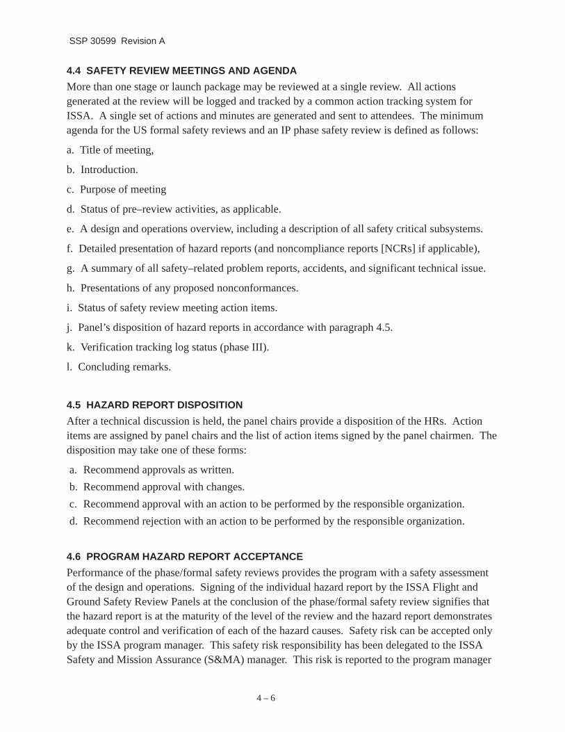
d. Ionizing Radiation: Ionizing radiation data sheet for each source (JSC Form 44, Figure 5.1.1–1).
e. Electrical Systems: Wire sizing and circuit protection diagram.
f. Components and elements of Mechanisms in critical applications: Identification of critical procedures and processes.
5 – 2
SSP 30599 Revision A
5.2 PHASE II SAFETY REVIEW The purpose of the Phase II safety review is to present to the panels the updated HRs that reflect the completed design and operations of the ISSA International Partner equipment to assure that all appropriate hazard controls have been implemented and that acceptable methods of verifying the controls have been identified in detail. The HRs shall be completed such that: (1) all hazards and hazard causes have been identified; (2) a means for eliminating, reducing, or controlling the risk has been defined and implemented; and (3) specific safety verification methods (i.e., test plans, analysis, and inspection requirements, etc.) have been finalized. Interfaces to be assessed shall include those between the orbiter and the launch package and among the various elements and distributed systems that comprise the ISSA stage configuration. Newly identified hazards shall be documented in additional hazard reports.
5.2.1 PHASE II DATA REQUIREMENTS The following data is required for the Phase II safety review:
a. GSE and Ground Operations at KSC
(1) GSE and Ground Operations description based on subject mission.
(2) Updated and additional ground HRs and appropriate support data (see paragraph 5.2.2).
(3) A list of technical operating procedures for ground processing with a preliminary designation showing which ones are hazardous,
(4) Updated ordnance data required by SSP 50004.
(5) Engineering drawings and stress analyses of safety critical subsystems when specifically requested.
(6) The status of action items assigned during Phase I.
(7) A list of safety–related failures and accidents.
b. Flight System Design and Operations
(1) Updated overview descriptions of hardware items and operations specified in paragraph 5.1.1b1. Individual increment phase descriptions as well as Assembly, Nominal, and Contingency Operation descriptions.
(2) Updated detailed descriptions and schematics/block diagrams (at a critical design review level of detail) for safety–critical systems and subsystems and their operations. The electrical schematics for safety critical circuits should depict the entire circuit from power source through the end function and to the power return. When shown in diagrams the inhibits and their controls should be clearly labeled.
(3) Status of action items assigned during Phase I safety review.
(4) Updated summary listing in the description section, of Orbiter or other ISSA segment provided critical services. Provided critical services used control and/or monitor hazards should be defined in appropriate HRs.
5 – 3

SSP 30599 Revision A
(5) Engineering drawings and stress analyses of safety critical sub–system when specifically requested.
(6) HRs and appropriate support data (see paragraphs 5.2.2 and 5.2.3).
(7) A list of safety related failures and accidents.
(8) A list of hazardous procedures (excluding ground processing).
5.2.2 PHASE II HAZARD REPORTS
The Phase II HRs shall be prepared by updating the safety hazards analysis to reflect the critical design level of detail and providing new and updated HRs to reflect the completed equipment design and flight/ground operating procedures. If the equipment design is changed from Phase I to Phase II such that a Phase I HR may be deleted, a brief statement of rationale for deleting the report shall be presented in the Phase II assessment report. Instructions for completion of Phase II HR forms are contained in appendix B. All current changes to the HRs are to be identified by a bar in the right–hand margin. The IP responsible safety manager and program manager shall sign and date each HR before submittal.
5.2.3 SUPPORT DATA – PHASE II HRS
All critical procedures/processes must be addressed, including the plan for verification. For hazards controlled by ”design for minimum risk,” the following listed set of support data in addition to that provided for Phase I, are required for Phase II.
a. Unpressurized Structures: Structural verification plan in accordance with SSP 30559 including:
(1) Summary of design loads derivation leading to critical load cases.
(2) Math model verification plan.
b. Pressurized Systems: Qualification and acceptance test plan.
c. Pyrotechnic Devices: For pyrotechnic devices which must operate reliably in order to meet safety requirements, the following data is required: Acceptance and qualification plans to include margin demonstration.
d. Materials: Fluids compatibility analysis.
e. Ionizing Radiation: Forms In KHB 1860.1, KSC Ionizing Radiation Protection Program, If required.
f. Non–Ionizing Radiation:
(1) List of equipment generating non–ion–zing radiation.
(2) Forms in KHB 1860.2, KSC Non–Ionizing Radiation Protection Program, if required.
g. Ground Commanding:
(1) Training plan for command controllers.
5 – 4

SSP 30599 Revision A
(2) List of hazardous commands including procedures used to preclude inadvertent commanding.
(3) Description of command hardware.
h. Components and elements of Mechanisms in critical applications: Mechanism verification plan.
5.3 PHASE III SAFETY REVIEW
The purpose of the Phase III safety review is assess the as–built design and operations of the IP segment elements for compliance with the safety requirements of SSP 50021 and SSP 50004 and obtain panel approval of the completed safety compliance data. The Phase III review provides the final safety assessment of equipment and operations.
5.3.1 PHASE III DATA REQUIREMENTS
The following data is required for the Phase III safety review:
a. GSE and around Operations at KSC
(1) GSE and Ground Operations description based on subject mission, including sub–systems that are safety–critical during ground processing.
(2) HRs and appropriate support data (see paragraph 5.3.2 and 5.3.3).
(3) Finalized list of technical/operating procedures with the hazardous procedures clearly identified.
(4) Identification of waiver/deviation requests to safety requirements. A signed copy of each approved waiver and deviation shall be included (see paragraph 6.0).
(5) A summary of all safety related failures and accidents.
(6) Engineering drawings and stress analyses of safety critical subsystems when specifically requested.
(7) Verification that each flight system pressure vessel has a pressure vessel logbook showing pressurization, history, fluid exposure, and other applicable data.
(8) Status of action items assigned during the Phase II safety review.
(9) Updated and finalized ordinance data required by SSP 50004.
(10) ISSA Safety Verification Tracking Log for ground operations only in accordance with appendix C (Figure C.1–1, Safety Verification Tracking Log) for this specific mission.
b. Flight System Design and Operation
(1) A list of all pyrotechnic initiators installed or to be installed. The list identifies, for each initiator, the function to be performed, the part number, the lot number, and the serial number.
(2) A final overview description of the design and operations of the hardware being addressed in the review. This includes descriptions of: IP elements; flight and
5 – 5

SSP 30599 Revision A
ground systems related to ISSA in–orbit manned and unmanned operations; airborne support equipment; operational scenarios related to assembly, start–up sequences, and orbital operations; and launch package, assembly, and stage configurations of the hardware. Briefly describe the hardware and operations in terms of significant characteristics and functions. Include figures or illustrations to show all major configurations and identify all hazardous systems and subsystems.
(3) Final detailed descriptions and schematics/block diagrams that reflects the as–built design for safety–critical systems and subsystems and their operations.
(4) A final summary listing of Orbiter or other ISSA segment provided safety–critical services. Orbiter services or other ISSA segment provided critical services used to control and/or monitor hazards should be defined in appropriate HRs.
(5) HRs and appropriate support data (see paragraphs 5.3.2 and 5.3.3).
(6) Engineering drawings and stress analyses of safety critical subsystems when specifically requested.
(7) Listing of waiver/deviation requests to safety related requirements. A signed copy of each approved waiver and deviation shall be included. (see paragraphs 6.0).
(8) A summary of all safety related failures and accidents.
(9) Closure of action items assigned during the Phase II safety review.
(10) ISSA Safety Verification Tracking Log (for flight hardware only) in accordance with appendix C (Figure C. 1–1) for this specific mission.
5.3.2 PHASE III HAZARD REPORTS
The Phase III HRs shall reflect the as–built design and operations of the equipment design and operation. Ideally, by Phase III, all safety analysis efforts are completed. The IP shall update the Phase II HRs to (1) reflect this final equipment design and operations, and (2) document the status and results of all completed verification work. All open verifications must be listed on a safety verification tracking log. This log allows the panel chairmen to sign the HRs indicating completion of the safety analyses, but with the understanding that approval for flight will be withheld until all verification activity is complete. Approval for flight will not be withheld for open verification activities that are part of nominal on–orbit activation activities, but failure to successfully accomplish these activities on orbit may constrain subsequent on–orbit operations. Open ground and flight verifications that have been identified as a constraint against ground processing must be closed before the applicable ground operation can be performed.
Instructions for completion of Phase III HR forms are contained in appendix B. All changes to the HRs since Phase II should be indicated by a bar in the right–hand margin. The IP safety manager and program manager shall sign and date each HR before submittal to the panels.
5 – 6

SSP 30599 Revision A
5.3.3 SUPPORT DATA – PHASE III HRS
For hazards controlled by ”design for minimum risk,” the following listed set of support data in addition to that provided for Phases I and II, are required for Phase III.
a. Unpressurized Structures: Fracture summary report.
b. Pressurized Systems:
(1) Fracture summary report.
(2) Summary of results of verification test/analyses.
c. Pyrotechnic devices: Summary of results of verification test/analyses.
d. Materials:
(1) Flammability assessment per SSP 30233.
(2) JSC Form 44, if required – update.
e. Components and elements of Mechanisms in critical applications: Summary of verification results.
(1) Trade/special studies supporting HRs.
(2) Flight HRs and appropriate support data (see paragraph 5.1.2).
(3) A summary listing in the SAR description section, of safety–critical services, and an explanation in the appropriate hazard reports of the orbiter services used to control and/or monitor hazards.
5.1.2 PHASE I HAZARD REPORTS
A Phase I HR shall be prepared for each hazard identified as a result of the safety analysis on the preliminary design and operations.
Instructions for completion of Phase I HR forms are contained in appendix B. The responsible safety manager shall sign and date each HR before submittal into the process.
Critical procedures/processes, which require special monitored verification, shall be identified in preliminary fashion. Also, for those hazards controlled by “design for minimum risk,” rather than failure tolerance requirements, a minimum set of support data, defined herein for Phase I are required. (appendix B contains the complete list of data elements for design for minimum risk hazards.)
a. Unpressurized Structures.
Preliminary plan for structural design and verification in accordance with SSP 30559, Structural Design and Verification Requirements, (including beryllium, glass [SSP 30560, Glass, Window, and Ceramic Structural Design and Verification Requirements], and composite/bonded structure) and SSP 50021, Verification Requirements section.
Fracture Control Plan in accordance with SSP 30558, Fracture Control Requirements for Space Station.
5 – 7

SSP 30599 Revision A
b. Pressurized Systems.
Fracture Control Plan.
Summary of design conditions for each pressurized system and certification approach.
5.4 POST PHASE III SAFETY ACTIVITY
When changes to the design or operation of a stage are required subsequent to the Phase III safety review but prior to launch, the ISSA participants shall assess those changes for possible safety implications, including their effect on all interfaces. The assessment shall be forwarded to the panels for approval. New or revised HRs and support data shall be prepared where applicable and also submitted for review. If the safety of the stage is affected, the need for a Delta safety review is determined by the Safety panel chairmen.
5 – 8

SSP 30599 Revision A
IONIZING RADIATION SOURCE DATA SHEET SPACE FLIGHT HARDWARE AND APPLICATIONS
IDENTIFICATION
1. PAYLOAD DESIGNATION/EXPERIMENT
PART A. RADIOISOTOPE SOURCES
3. SOURCE USING ORGANIZATION
5. CONTACT
7. PAYLOAD SPONSOR/MANAGER
9. CONTACT
2. INCREMENT
4. ADDRESS
6. TELEPHONE
8. ADDRESS
10. TELEPHONE
Complete Items 1 through 10 and Part A for radioisotope sources and Part B for ionizing radiation–producing equipment
I. SOURCE DESCRIPTION
1. ISOTOPE
4. CHEMICAL FORM
6. SOURCE SEALED
8. MANUFACTURER
II. SOURCE USE DATA
DETAILS ON SEALING, TECHNIQUES AND DIMENSIONS
III. SOURCE DIAGRAM
PURPOSE:
EXTERNAL CALIBRATION
OTHER (Describe)
CREW INVOLVEMENT/REQUIREMENTS (Include nominal and contingent situations.)
INFLIGHT CALIBRATION
5. PHYSICAL STATE
7. IDENTIFICATION NOS.
9. ADDRESS
2. TOTAL QUANTITY (MILLICURIE)
(Include determination data.)
3. NUMBER OF SOURCES
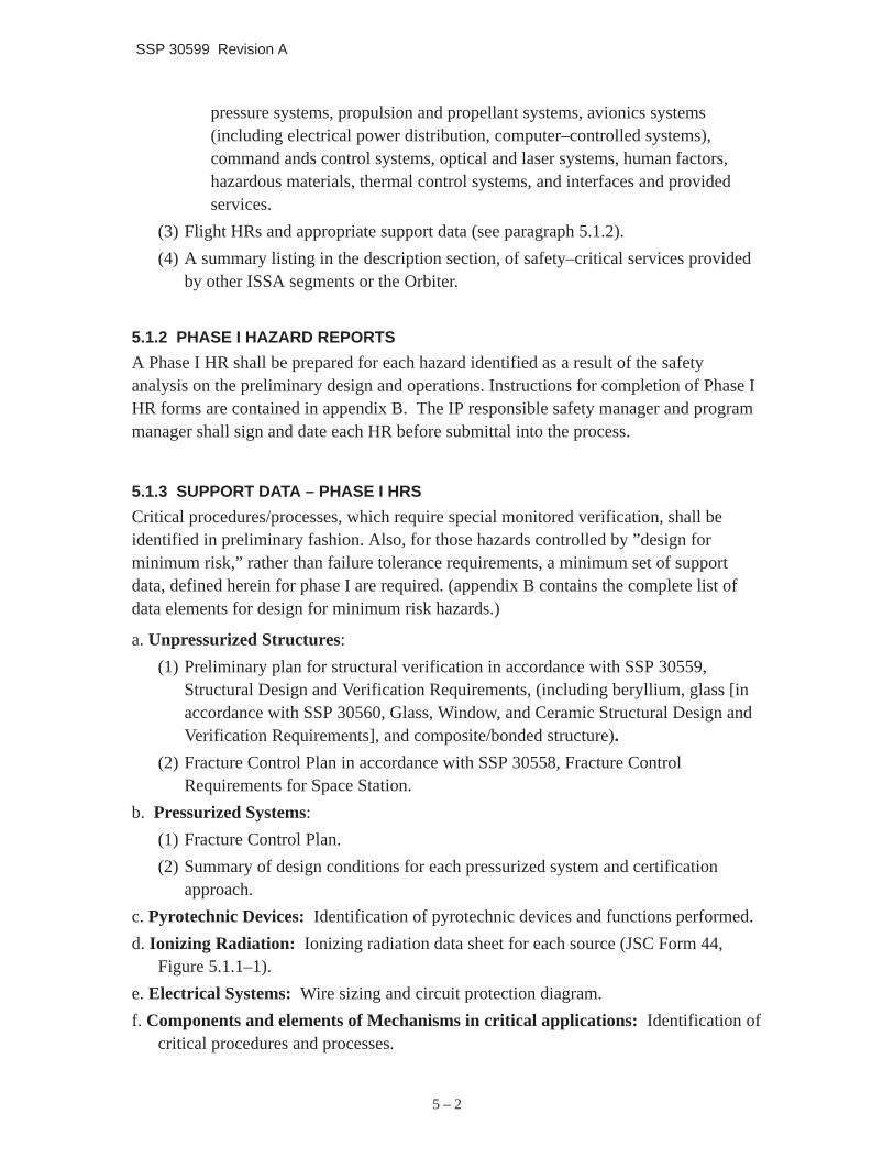
FIGURE 5.1.1–1 IONIZING RADIATION DATA SHEET, JSC FORM 44 (PAGE 1 OF 2)
5 – 9

SSP 30599 Revision A
MMHG
VI. POST–FLIGHT DISPOSITION
1. TYPE OF RADIATION PRODUCED:
IV. TEST DATA
1. DATA SOURCE LEAK TESTED 2. RESULTS (MICROCURIE)
3. THERMO–VACUUM QUALIFIED TO:
DEGREE C. DATE
V. PRE–FLIGHT TRANSFERS
1. LOCATIONS WHERE SOURCE IS TO USED OR STORED AND APPROXIMATE DATES
A. LOCATIONS TOB. DATED FROM
2. SOURCE CUSTODIAN/RADIATION SAFETY OFFICER TELEPHONE
OUTLINE REQUIREMENTS:
PART B IONIZING RADIATION PRODUCING EQUIPMENT
2. MAXIMUM ENERGY LEVEL
4. DURATION OF OPERATION
3. OPERATING ENERGY LEVEL
5. NO. OF UNITS
6. PULSED UNIT DUTY CYCLE
II. RADIATION CHARACTERISTICS
III. EQUIPMENT USE DATA
I. EQUIPMENT CHARACTERISTICS
1. CREW INVOLVEMENT/PROCEDURES:
2. RADIATION PRODUCTION WARNING SYSTEM: 3. SAFETY INTERLOCK SYSTEM:
YES (Describe) NO YES (Describe) NO
1. RADIATION INTENSITY OF FLIGHT CONFIGURED UNIT 2. SECONDARY RADIATION PRODUCED
HOURS TOTAL, ALL UNITS
RAD/HR @ METERS KEV
ENERGY LEVEL TYPE
FIGURE 5.1.1–1 IONIZING RADIATION DATA SHEET, JSC FORM 44 (PAGE 2 OF 2)
5 – 10

SSP 30599 Revision A
6.0 NONCOMPLIANCE WITH SPACE STATION REQUIREMENTS
Configuration control of ISSA systems must be maintained in order to preserve both the level of confidence achieved during the phase safety review process and the level of accepted safety risk. Any changes to baselined ISSA documentation or a request for a waiver/deviation to an ISSA requirement, requires generation of a formal Change Request (CR). CRs are reviewed by participating organizations for an assessment of safety ramifications. The organization originating a CR is responsible for providing a safety assessment of the change proposed. This assessment shall include the rationale for acceptance of the change and the associated risks. If deemed necessary, the panel chairmen may convene a meeting of the safety review panel to address significant CRs to obtain an overall safety consensus. Necessary changes to the design or operation of the manned base required in real time, as determined by the Space Station Control Center (SSCC), are exempt. The assessment of these changes, including new or revised hazard reports and supporting data, shall be presented to the panels for review in a timely manner.
The panel chairmen provide a recommendation on the acceptance or rejection of a CR at the SSCB through the S&MA Manager.
Acceptance of a waiver/deviation is documented on an HR.
6 – 1

SSP 30599 Revision A
7.0 SIMILAR AND REFLOWN EQUIPMENT
”Reflown Equipment” is ISSA flight equipment that was previously launched and utilized on orbit and are manifested for reflight and reuse. ”Similar Equipment” is hardware/software which is of the same or similar design to hardware/software which has been previously certified by the flight safety review panel for its safety. Variances to the basic procedures of paragraph 5.0 have been developed for similar and reflown equipment to eliminate unnecessary duplication of effort from previously accomplished safety activity.
The user of the reflown /similar equipment(i.e., NASA, the ISSA Prime Contractor, the Prime Contractors Product Groups or an IP) is responsible for the safety of the similar/reflown equipment and associated interfaces. To fulfill this responsibility, the user shall assess the previously approved safety data of the similar/reflown equipment for applicability to the new application and make all appropriate changes. The number and depth of the phase safety reviews to be conducted to assess reflown/similar equipment should be discussed at an early safety review meeting.
The following unique data for the similar/reflown equipment shall be submitted:
a. Identification of all similar/reflown equipment to be used and the baseline safety analyses.
b. Assessment of each similar/reflown equipment to indicate that the proposed use is the same as that analyzed and documented.
c. New or revised hazard reports, additional data, and identification of deleted HRs. Identification and assessment of changes in hardware/software and operations which have safety impact.
d. An assessment of the safety verification methods contained in the baseline safety analysis to determine which verification must be reaccomplished.
e. A list and description of safety noncompliances including the acceptance rationale for each..
f. Assessment of limited life items for reflown hardware.
g. Description of maintenance, structural inspections, and refurbishment of reflown hardware and assessment of safety impact.
h. Assessment of all failures and anomalies during previous usage of the similar/reflown element with corrective action taken and rationale for extended use.
i. Unique flight article data required by paragraph 5.3.1, items a.7 and b.1.
j. Ionizing radiation data sheet for each source (JSC Form 44, Figure 5.1.1–1) as applicable.
7 – 1
SSP 30599 Revision A
APPENDIX A ABBREVIATIONS AND ACRONYMS
AI Action Item
AIT Analysis and Integration Team
CDR Critical Design Review
CE Cargo Element
CoFR Certification of Flight Readiness
CR Change Request
DCR Design Certification Review
EMS Engineering Master Schedule
e.g. Example
etc. Etcetera
FRR Flight Readiness Review
GFE Government Furnished Equipment
GSE Ground Support Equipment
GSRP Ground Safety Review Panel
HAR Hazard Assessment Report
HR Hazard Report
IHA Integrated Hazard Analysis
IP International Partners
IPT Integrated Product Team
ISSA International Space Station Alpha
ISSAP International Space Station Alpha Program
JPDRD Joint Program Definition and Requirements Document
JSC Johnson Space Center
KSC Kennedy Space Center
L–2 Launch Minus 2 Day
LP Launch Package
LP/S Launch Package/Stage
LPI Launch Package Integration
LPM Launch Package Manager
MB Mission Build
A – 1
SSP 30599 Revision A
MTC Man–tended Capability
MUA Material Usage Agreement
NASA National Aeronautics and Space Administration
NCR Non–Compliance Report
NSTS National Space Transportation System
PCB Program Control Board
PDR Preliminary Design Review
PG Product Group
PSRP Payload Safety Review Panel
RAD Radiation Absorbed Dose
S&MA Safety and Mission Assurance
SAR Safety Assessment Report
SOW Statement of Work
SRM&QA Safety, Reliability, Maintainability, and Quality Assurance
SRP Safety Review Panel
SSCB Space Station Control Board
SSCC Space Station Control Center
SSP Space Shuttle Program
TBD To Be Determined
UF Utilization Flight
US United States
VCN Verification Completion Notice
WP Work Package
A – 2
SSP 30599 Revision A
APPENDIX B INSTRUCTIONS FOR ISSA HAZARD REPORT FORM
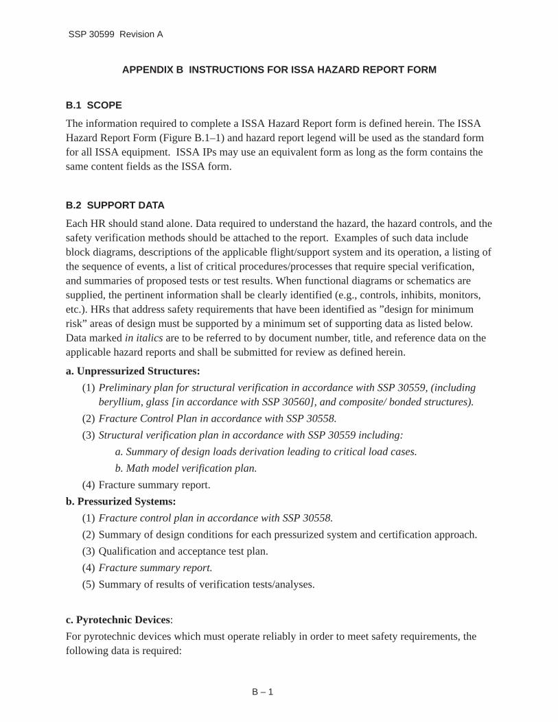
B.1 SCOPE
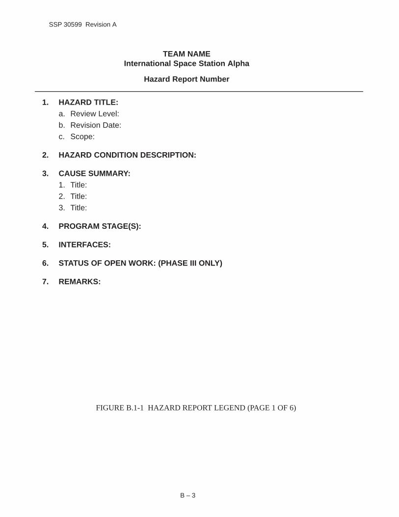
The information required to complete a ISSA Hazard Report form is defined herein. The ISSA Hazard Report Form (Figure B.1–1) and hazard report legend will be used as the standard form for all ISSA equipment. ISSA IPs may use an equivalent form as long as the form contains the same content fields as the ISSA form.
B.2 SUPPORT DATA
Each HR should stand alone. Data required to understand the hazard, the hazard controls, and the safety verification methods should be attached to the report. Examples of such data include block diagrams, descriptions of the applicable flight/support system and its operation, a listing of the sequence of events, a list of critical procedures/processes that require special verification, and summaries of proposed tests or test results. When functional diagrams or schematics are supplied, the pertinent information shall be clearly identified (e.g., controls, inhibits, monitors, etc.). HRs that address safety requirements that have been identified as ”design for minimum risk” areas of design must be supported by a minimum set of supporting data as listed below. Data marked in italics are to be referred to by document number, title, and reference data on the applicable hazard reports and shall be submitted for review as defined herein.
a. Unpressurized Structures:
(1) Preliminary plan for structural verification in accordance with SSP 30559, (including beryllium, glass [in accordance with SSP 30560], and composite/ bonded structures).
(2) Fracture Control Plan in accordance with SSP 30558.
(3) Structural verification plan in accordance with SSP 30559 including:
a. Summary of design loads derivation leading to critical load cases.
b. Math model verification plan.
(4) Fracture summary report.
b. Pressurized Systems:
(1) Fracture control plan in accordance with SSP 30558.
(2) Summary of design conditions for each pressurized system and certification approach.
(3) Qualification and acceptance test plan.
(4) Fracture summary report.
(5) Summary of results of verification tests/analyses.
c. Pyrotechnic Devices:
For pyrotechnic devices which must operate reliably in order to meet safety requirements, the following data is required:
B – 1
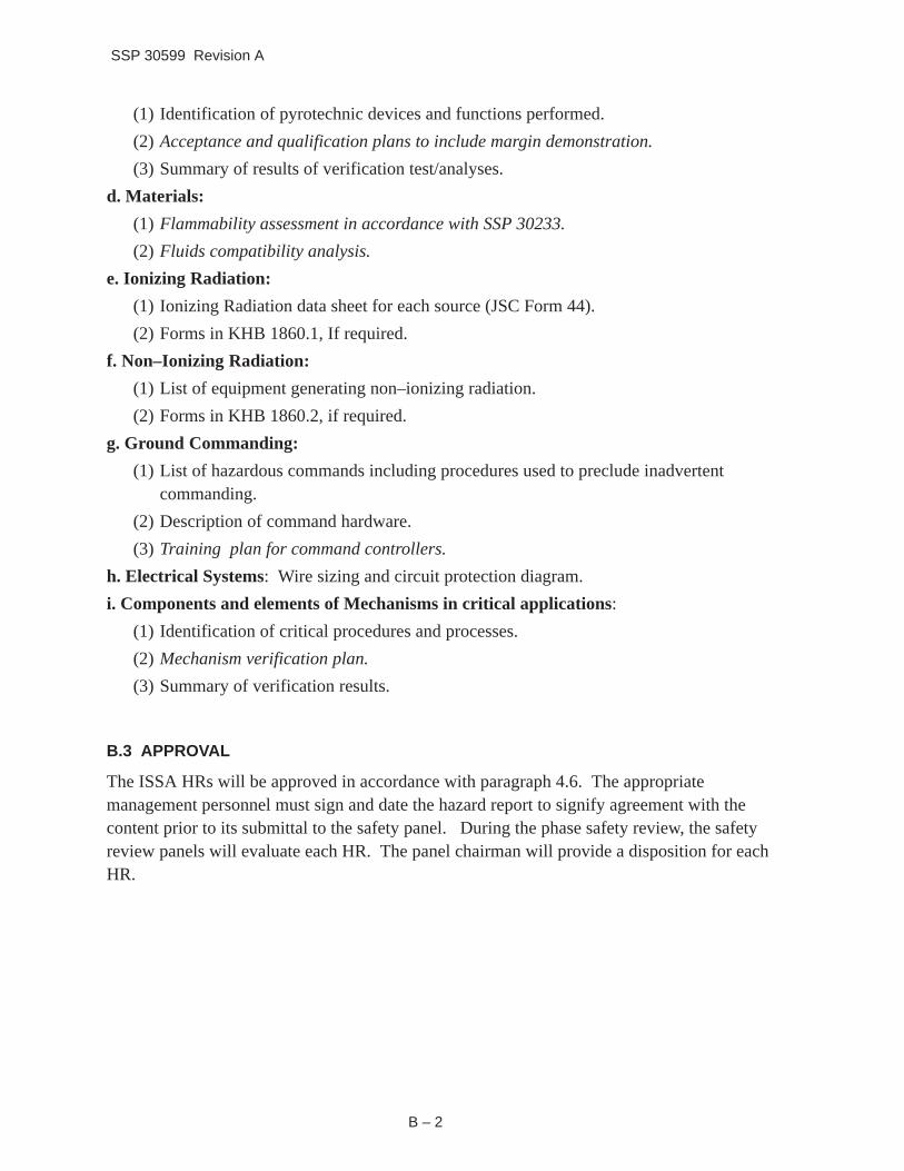
SSP 30599 Revision A
(1) Identification of pyrotechnic devices and functions performed.
(2) Acceptance and qualification plans to include margin demonstration.
(3) Summary of results of verification test/analyses.
d. Materials:
(1) Flammability assessment in accordance with SSP 30233.
(2) Fluids compatibility analysis.
e. Ionizing Radiation:
(1) Ionizing Radiation data sheet for each source (JSC Form 44).
(2) Forms in KHB 1860.1, If required.
f. Non–Ionizing Radiation:
(1) List of equipment generating non–ionizing radiation.
(2) Forms in KHB 1860.2, if required.
g. Ground Commanding:
(1) List of hazardous commands including procedures used to preclude inadvertent commanding.
(2) Description of command hardware.
(3) Training plan for command controllers.
h. Electrical Systems: Wire sizing and circuit protection diagram.
i. Components and elements of Mechanisms in critical applications:
(1) Identification of critical procedures and processes.
(2) Mechanism verification plan.
(3) Summary of verification results.
B.3 APPROVAL
The ISSA HRs will be approved in accordance with paragraph 4.6. The appropriate management personnel must sign and date the hazard report to signify agreement with the content prior to its submittal to the safety panel. During the phase safety review, the safety review panels will evaluate each HR. The panel chairman will provide a disposition for each HR.
B – 2
SSP 30599 Revision A
TEAM NAME International Space Station Alpha
Hazard Report Number
1. HAZARD TITLE: a. Review Level:
b. Revision Date:
c. Scope:
2. HAZARD CONDITION DESCRIPTION:
3. CAUSE SUMMARY: 1. Title:
2. Title:
3. Title:
4. PROGRAM STAGE(S):
5. INTERFACES:
6. STATUS OF OPEN WORK: (PHASE III ONLY)
7. REMARKS:
FIGURE B.1-1 HAZARD REPORT LEGEND (PAGE 1 OF 6)
B – 3
__________________________________________________________________
SSP 30599 Revision A
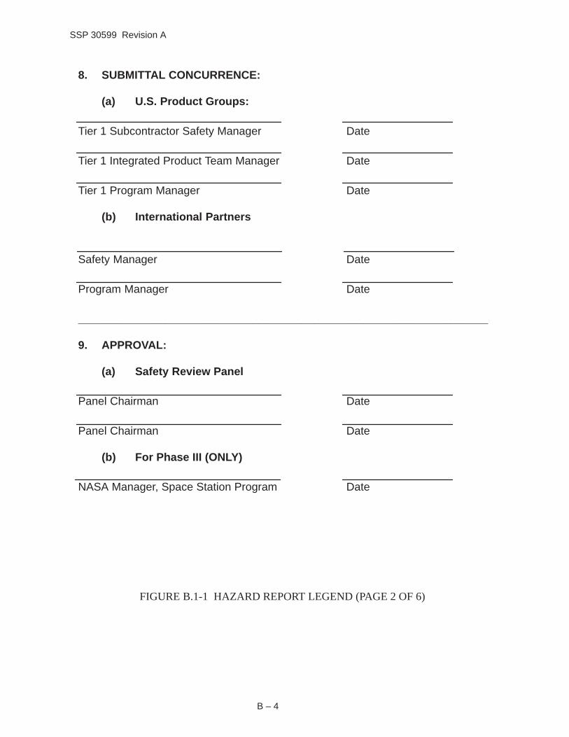
8. SUBMITTAL CONCURRENCE:
(a) U.S. Product Groups:
Tier 1 Subcontractor Safety Manager Date
Tier 1 Integrated Product Team Manager Date
Tier 1 Program Manager Date
(b) International Partners
Safety Manager Date
Program Manager Date
9. APPROVAL:
(a) Safety Review Panel
Panel Chairman Date
Panel Chairman Date
(b) For Phase III (ONLY)
NASA Manager, Space Station Program Date
FIGURE B.1-1 HAZARD REPORT LEGEND (PAGE 2 OF 6)
B – 4
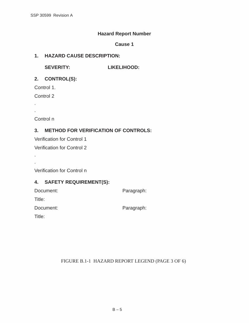
SSP 30599 Revision A
Hazard Report Number
Cause 1
1. HAZARD CAUSE DESCRIPTION:
SEVERITY: LIKELIHOOD:
2. CONTROL(S):
Control 1.
Control 2
.
.
Control n
3. METHOD FOR VERIFICATION OF CONTROLS:
Verification for Control 1
Verification for Control 2
.
.
Verification for Control n
4. SAFETY REQUIREMENT(S):
Document: Paragraph:
Title:
Document: Paragraph:
Title:
FIGURE B.1-1 HAZARD REPORT LEGEND (PAGE 3 OF 6)
B – 5

SSP 30599 Revision A
5. MISSION PHASE(S): Launch Processing:
Launch: Rendezvous/Docking:
Deployment: Orbital Assembly & Checkout: On-Orbit Operation: On-Orbit Maintenance: Return/Decommissioning:
6. PROGRAM STAGE(S):
7. DETECTION AND WARNING METHOD(S):
8. CAUSE REMARKS:
9. CIL REFERENCE:
10. POINT OF CONTACT:
Name: Telephone:
FIGURE B.1-1 HAZARD REPORT LEGEND (PAGE 4 OF 6)
B – 6

SSP 30599 Revision A
Hazard Report Number
Cause 2
1. HAZARD CAUSE DESCRIPTION:
SEVERITY: LIKELIHOOD:
2. CONTROL(S):
Control 1.
Control 2
.
.
Control n
3. METHOD FOR VERIFICATION OF CONTROLS:
Verification for Control 1
Verification for Control 2
.
.
Verification for Control n
4. SAFETY REQUIREMENT(S):
Document: Paragraph:
Title:
Document: Paragraph:
Title:
FIGURE B.1-1 HAZARD REPORT LEGEND (PAGE 5 OF 6)
B – 7

SSP 30599 Revision A
5. MISSION PHASE(S): Launch Processing:
Launch: Rendezvous/Docking:
Deployment: Orbital Assembly & Checkout: On-Orbit Operation: On-Orbit Maintenance : Return/Decommissioning:
6. PROGRAM STAGE(S):
7. DETECTION AND WARNING METHOD(S):
8. CAUSE REMARKS:
9. CIL REFERENCE:
10. POINT OF CONTACT:
Name: Telephone:
FIGURE B.1-1 HAZARD REPORT LEGEND (PAGE 6 OF 6)
B – 8

SSP 30599 Revision A
HAZARD REPORT LEGEND FOR TOP LEVEL PAGES
HAZARD REPORT NUMBER: AAAA-NNNN-RR
A. Identification of Team originator:
N. Sequential number. The number must be unique to the team originator and identify entries associated with a single category of hazard.
R. Alpha character indicating the revision of the report.
1. TITLE: Enter a brief description of the hazard in terms of hazard initiator, action or consequence.
a. REVIEW LEVEL: Enter the milestone review the hazard report was written for (Phase I, Phase II, Phase III, etc.)
b. REVISION DATE: Enter the date the hazard report was entered or revised.
c. SCOPE: Describe the scope of the hazards being addressed including, as appropriate, the end item, system, subsystem, Orbital Replacement Unit (ORU), and operation.
2. HAZARD CONDITION DESCRIPTION: The hazard description should define the risk situation including the unsafe act or conditions and its effect on station, shuttle, or personnel.
3. CAUSE SUMMARY: List the titles of causes associated with this hazard.
4. PROGRAM STAGES: Using the ISSA Assembly Sequence Manifest, identify the Stage(s) in which the hazard manifests itself.
5. INTERFACES: Identify the segments of the Space Station that may be associated with detection or control of the identified hazard.
6. STATUS OF OPEN WORK: Indicate the status of each open verification method. (Phase III only)
7. REMARKS : Entries here should include any information relating to the hazard but not fully covered in any other item field.
8. SUBMITTAL CONCURRENCE: The indicated managers from the applicable End-Item developer shall sign the hazard report prior to release outside of the company.
B – 9

SSP 30599 Revision A
Signature indicates agreement with the content at the current phase or level of program maturity and accuracy.
9. APPROVAL: The indicated Safety Review Panel Chairman shall sign the hazard report. The signature indicates agreement with the content at the current phase or level of program maturity and accuracy.
B – 10

SSP 30599 Revision A
HAZARD REPORT LEGEND
FOR EACH CAUSE PAGE
1. HAZARD CAUSE DESCRIPTION: Describe the types of phenomena that are of concern, i.e., the key factor to be assessed as leading to the expected outcome/consequence.
SEVERITY: This index quantifies the worst case accident or undesired event resulting from this cause. Severity levels are I (Catastrophic) and II (Critical) as specified in Table B.1-1, Severity Category.
LIKELIHOOD: The likelihood (probability of occurrence) of this hazard cause manifesting itself after controls have been implemented. Likelihood levels are A, B, C, and D, with A being the most probable as specified in Table B.1-2, Likelihood of Occurrence.
2. CONTROL(S): Provide a description of all the necessary design/operational controls needed to mitigate this hazard cause, including documentation references, if applicable. The control methods identify techniques which will be or are used to control or eliminate the hazard cause and thereby satisfy the Safety Requirement. Sufficient detail shall be provided to clearly reflect controls which mitigate/control the hazard. The hazard controls shall be numbered to provide linkages with Method of Verification of Controls.
3. METHOD FOR VERIFICATION OF CONTROL(S): Identify for each control method the method of verification (procedure/processes), including document number if applicable, used to assure the effectiveness of the hazard controls. Each control verification method must link with its corresponding control, and when more than one method of verification is listed for a control, the verification methods will be listed separately (e.g., 1a, 1b, 2, 3a, 3b, 3c). Each verification method description shall include sufficient detail or explanation of the testing, inspection, or analysis which mitigates the hazard to support hazard closure or risk acceptance.
4. SAFETY REQUIREMENT(S): Identify the design requirements used this cause.
5. MISSION PHASE(S): Identify the phase of the mission in which the hazard manifests itself. An (X) indicates that the identified phase is affected by the hazard. An (O) indicates that it has been considered but is not affected.
Launch Processing covers the time period where the hardware arrives at launch site, is processed into the launch vehicle and extends to T-0.
Launch covers the time period from T-0 through orbital insertion.
Rendezvous/Docking covers the time period from orbital insertion until launch vehicle is docked to the Stage.
B – 11
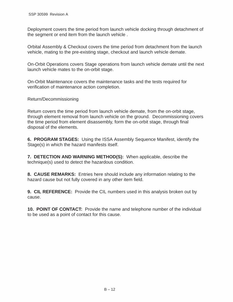
SSP 30599 Revision A
Deployment covers the time period from launch vehicle docking through detachment of the segment or end item from the launch vehicle .
Orbital Assembly & Checkout covers the time period from detachment from the launch vehicle, mating to the pre-existing stage, checkout and launch vehicle demate.
On-Orbit Operations covers Stage operations from launch vehicle demate until the next launch vehicle mates to the on-orbit stage.
On-Orbit Maintenance covers the maintenance tasks and the tests required for verification of maintenance action completion.
Return/Decommissioning
Return covers the time period from launch vehicle demate, from the on-orbit stage, through element removal from launch vehicle on the ground. Decommissioning covers the time period from element disassembly, form the on-orbit stage, through final disposal of the elements.
6. PROGRAM STAGES: Using the ISSA Assembly Sequence Manifest, identify the Stage(s) in which the hazard manifests itself.
7. DETECTION AND WARNING METHOD(S): When applicable, describe the technique(s) used to detect the hazardous condition.
8. CAUSE REMARKS: Entries here should include any information relating to the hazard cause but not fully covered in any other item field.
9. CIL REFERENCE: Provide the CIL numbers used in this analysis broken out by cause.
10. POINT OF CONTACT: Provide the name and telephone number of the individual to be used as a point of contact for this cause.
B – 12

SSP 30599 Revision A
TABLE B.1-1 SEVERITY CATEGORY
Description Category Mishap Definition
Catastrophic I Any condition which may cause a disabling or fatal personnel injury, or cause loss of one of the following: the orbiter, ISSA or major ground facility. Loss of ISSA: Loss of the ISSA is to be limited to those conditions resulting from failures or damages to elements in the critical path of the ISSA that render the ISSA unusable for further operations, even with contingency repair or replacement of hardware, or which render the ISSA in a condition which prevents further rendezvous and docking operations with ISSA launch elements.
Critical II Any condition which may cause a non–disabling personnel injury, severe occupational illness; loss of a ISSA element, on–orbit life sustaining function or emergency system; or involves damage to the orbiter or a major ground facility. For safety failure tolerance considerations, critical hazards include loss of ISSA elements that are not in the critical path for station survival or damage to an element in the critical path which can be restored through contingency repair.
B – 13

SSP 30599 Revision A
TABLE B.1-2 LIKELIHOOD OF OCCURRENCE
Description Category Mishap Definition
Probable A Expected to happen in the life of the program.
Infrequent B Could happen in the life of the program. Controls have significant limitations or uncertainties.
Remote C Could happen in the life of the program, but not expected. Controls have minor limitations or un-certainties.
Improbable D Extremely remote possibility that it will happen in the life of the program. Strong controls are in place.
B – 14

SSP 30599 Revision A
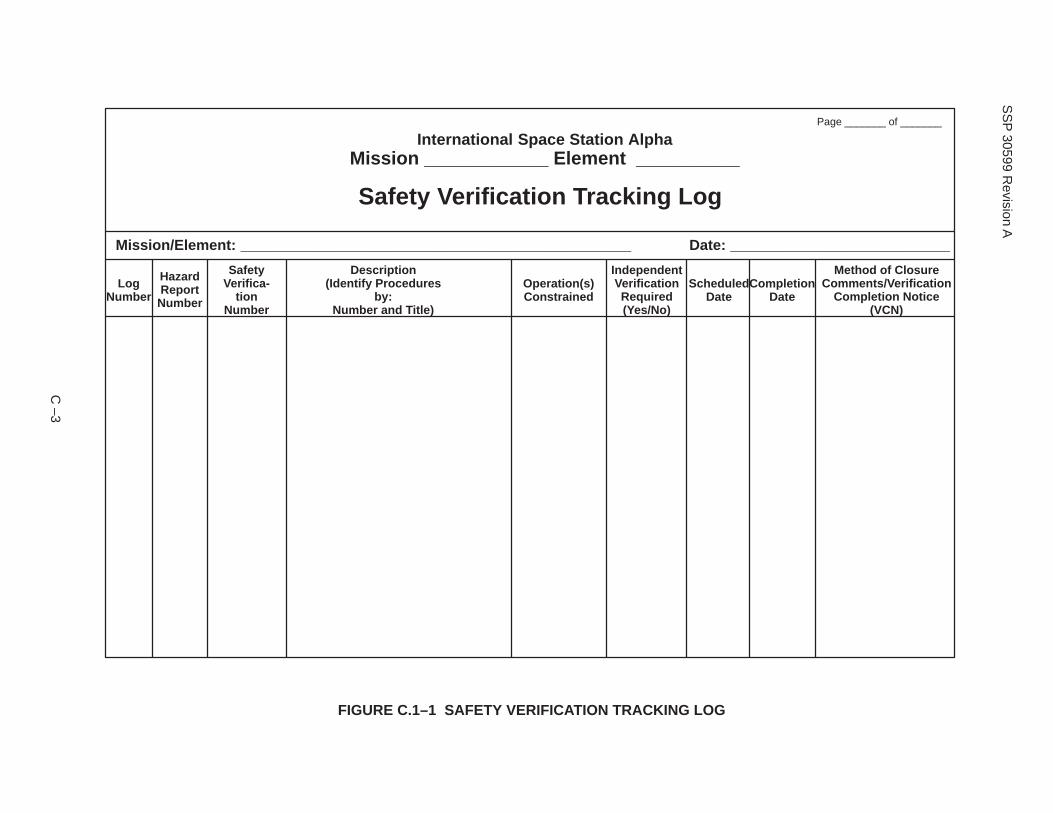
APPENDIX C INSTRUCTIONS FOR ISSA SAFETY VERIFICATION TRACKING LOG
C.1 SCOPE
This appendix describes the usage of the ISSA safety verification tracking log (Figure C.1–1), and provides instructions for its completion.
C.2 USAGE
The verification tracking log is used to formally document and status ISSA safety verification work that is not completed at the time the final safety assessment report is prepared. (All completed verification work is documented on the appropriate hazard reports.) These verification requirements will be acted on in accordance with the process described in the Program Master Verification Plan. If all activities associated with the safety analyses (other than the open verification) are completed, the panel chairmen may sign the hazard reports indicating panel acceptance of the safety work, but with the understanding that final approval of the hazard is not complete until the HR is baselined and all applicable verification activity is completed. Items requiring on–orbit verification will be incorporated in approved assembly and checkout procedures. The procedure numbers will be referenced in the Log.
C.3 INSTRUCTIONS
Instructions for the completion of the ISSA Safety Verification Tracking Log are as follows:
a. TITLE
The title is used to identify whether the tracking log is for a mission or a specific equipment verification.
b. PAGE
The specific page number followed by the total number of pages.
c. ELEMENT/MISSION
The name of the element, experiment, etc., or the mission number.
d. DATE
Date completed or updated.
e. LOG NO .
An alphanumeric designation used to identify and track each verification item. These designations will be assigned by the project organization when the log is first submitted.
f. HAZARD REPORT NUMBER
The number of the hazard report containing the verification item.
g. SAFETY VERIFICATION NUMBER
The number from the applicable hazard report (Safety Verification Method block) for the specific verification item.
C –1

SSP 30599 Revision A
h. DESCRIPTION
The specific verification remaining open. Procedures will be identified by number and title.
i. OPERATION(S) CONSTRAINED
The specific operation(s) that this verification is a constraint against. Closure of this verification item must be accomplished before the listed operation(s) can be performed.
j. INDEPENDENT VERIFICATION REQUIRED (YES/NO)
The need (Yes/No) for an independent verification of the specific item.
k. SCHEDULED DATE
The date planned for completion of the verification.
l. COMPLETION DATE
The date this verification was completed.
m. METHOD OF CLOSURE/COMMENTS/VERIFICATION COMPLETION NOTICE (VCN)
The method by which this open verification has been confirmed closed, and additional information or remarks.
C –2
SS
P 30599 R
evision A
International Space Station Alpha Mission ____________ Element __________
Safety Verification Tracking Log
Page _______ of _______
Mission/Element: ________________________________________________ Date: ___________________________
Log Number
Hazard Report Number
Safety Verifica-
tion Number
Description (Identify Procedures
by: Number and Title)
Operation(s) Constrained
Independent Verification Required (Yes/No)
Scheduled Date
Completion Date
Method of Closure Comments/Verification
Completion Notice (VCN)
FIGURE C.1–1 SAFETY VERIFICATION TRACKING LOG
C –3


![Safety Gate - SGNA036GV - Revision Q.ckd [Part1]](https://img.dokumen.tips/doc/110x75/5e8a1ab66da15e5e9a236b0b/safety-gate-sgna036gv-revision-qckd-part1-.jpg)