Embed Size (px)
Citation preview

02
Drive Technology \ Drive Automation \ System Integration \ Services
Manual
Edition 07/2013 20151756 / EN
Safe Brake SystemSynchronous Servomotors

SEW-EURODRIVE—Driving the world

1 General Information ............................................................................................ 51.1 Use of this documentation .......................................................................... 51.2 Structure of the safety notes ....................................................................... 51.3 Rights to claim under warranty ................................................................... 61.4 Content of the documentation..................................................................... 61.5 Exclusion of liability..................................................................................... 61.6 Other applicable documentation ................................................................. 61.7 Product names and trademarks.................................................................. 61.8 Copyright..................................................................................................... 6
2 Safety Notes ........................................................................................................ 72.1 General information .................................................................................... 72.2 Target group ............................................................................................... 72.3 Designated use ........................................................................................... 82.4 Transport / storage...................................................................................... 82.5 Setup .......................................................................................................... 92.6 Electrical connection ................................................................................... 92.7 Startup / operation .................................................................................... 10
3 System Description........................................................................................... 113.1 System overview....................................................................................... 12
4 Functional Safety .............................................................................................. 134.1 Safety functions ........................................................................................ 134.2 Performance levels that can be achieved ................................................. 154.3 Differences between BY and BY(FS) brakes............................................ 21
5 Components ...................................................................................................... 225.1 Motor......................................................................................................... 225.2 Gear units ................................................................................................. 225.3 Brake......................................................................................................... 235.4 Safety-rated encoders............................................................................... 255.5 Safety-rated brake control......................................................................... 265.6 Frequency inverters .................................................................................. 295.7 SEW controller ......................................................................................... 305.8 MOVISAFE® UCS..B safety module ......................................................... 315.9 Prefabricated cables ................................................................................. 325.10 Additional documentation.......................................................................... 33
6 Project Planning................................................................................................ 346.1 Project planning procedure for BY..(FS) brakes ....................................... 346.2 Brake BY..(FS).......................................................................................... 39
7 Technical Data................................................................................................... 467.1 Technical data of BY brakes ..................................................................... 467.2 Safety characteristics................................................................................ 51
Manual – Safety-Rated Drive System
3
4
8 Appendix............................................................................................................ 528.1 Mounting positions of CMP servomotors .................................................. 52
Index................................................................................................................... 53
Manual – Safety-R
ated Drive System
1Use of this documentationGeneral Information
Safety-Rated Drive System1 General Information1.1 Use of this documentation
The documentation is an integral part of the product and contains important informationon operation and service. The document is for all persons who plan, configure, and startup safety-rated brakes and safety-rated braking systems.
The documentation must be accessible and legible. Make sure that persons responsiblefor the system and its operation, as well as persons who work independently on the unit,have read through the documentation carefully and understood it. If you are unclearabout any of the information in this documentation, or if you require further information,contact SEW-EURODRIVE.
1.2 Structure of the safety notes1.2.1 Meaning of signal words
The following table shows the graduation and meaning of the signal words for safetynotes, warnings regarding potential risks of damage to property, and other notes.
1.2.2 Design of the section-related safety notesSection-related safety notes do not apply to a specific action, but to several actions per-taining to one subject. The symbols used either indicate a general hazard or a specifichazard.
This is the formal structure of a safety note for a specific section:
1.2.3 Design of the embedded safety notesEmbedded safety notes are directly integrated into the instructions just before the de-scription of the dangerous action.
This is the formal structure of an embedded safety note:
• SIGNAL WORD! Type and source of hazard.
Possible consequence(s) if disregarded.
– Measure(s) to prevent the hazard.
Signal word Meaning Consequences if disregardedDANGER! Imminent hazard Severe or fatal injuries
WARNING! Possible dangerous situation Severe or fatal injuries
CAUTION! Possible dangerous situation Minor injuries
NOTICE Possible damage to property Damage to the drive system or its envi-ronment
INFORMATION Useful information or tip: Simpli-fies handling of the drive sys-tem.
SIGNAL WORD!Type and source of danger.
Possible consequence(s) if disregarded.• Measure(s) to prevent the danger.
Manual – Safety-Rated Drive System
5
6
1 ights to claim under warrantyeneral Information
1.3 Rights to claim under warrantyA requirement of fault-free operation and fulfillment of any rights to claim under limitedwarranty is that you adhere to the information in the documentation. Therefore read thedocumentation before you start working with the unit.
1.4 Content of the documentationThis document contains additional safety-related information and conditions for opera-tion in safety-related applications.
1.5 Exclusion of liabilityYou must comply with the information contained in this documentation to ensure safeoperation and to achieve the specified product characteristics and performance fea-tures. SEW-EURODRIVE assumes no liability for injury to persons or damage to equip-ment or property resulting from non-observance of these operating instructions. In suchcases, any liability for defects is excluded.
1.6 Other applicable documentationThis document supplements the operating instructions and limits the application notesaccording to the following information. Use this document only together with the operat-ing instructions.
1.7 Product names and trademarksAll product names in this documentation are trademarks or registered trademarks oftheir respective titleholders.
1.8 Copyright© 2013 SEW-EURODRIVE. All rights reserved.
Unauthorized duplication, modification, distribution or any other use of the whole or anypart of this documentation is strictly prohibited.
RG
Manual – Safety-Rated Drive System

2General informationSafety Notes
2 Safety Notes2.1 General information
The following basic safety notes must be read carefully to prevent injury to persons anddamage to property. The operator must ensure that the basic safety notes are read andadhered to.
Ensure that persons responsible for the machinery and its operation as well as personswho work independently have read through the documentation carefully and understoodit. If you are unclear about any of the information in this documentation, or if you requirefurther information, please contact SEW-EURODRIVE.
Also adhere to the supplementary safety notes in this document and in the documenta-tion of the connected components from SEW-EURODRIVE.
This document does not replace the detailed documentation of the connected compo-nents.
This document assumes that the user has access to and is familiar with the documen-tation for all connected components from SEW-EURODRIVE.
Never install damaged products. Never take damaged products into operation. Submita complaint to the shipping company immediately in the event of damage.
Removing covers without authorization, improper use or incorrect installation and oper-ation may result in severe injuries to persons or damage to machinery. Consult the doc-umentation for additional information.
2.2 Target groupThe document is for all persons who plan, configure, and start up safety-rated brakesand safety-rated braking systems.
Any work with software may only be performed by adequately qualified personnel. Qual-ified personnel in this context are persons who have the following qualifications:
• Appropriate instruction.
• Knowledge of this documentation and other applicable documentation.
• SEW-EURODRIVE recommends additional product training for products that areoperated using the respective software.
Any mechanical work on the components may only be performed by adequately quali-fied personnel. Qualified personnel in the context of this documentation are personsfamiliar with the design, mechanical installation, troubleshooting and servicing of theproduct who possess the following qualifications:
• Training in mechanical engineering, e.g. as a mechanic or mechatronics technician(final examinations must have been passed).
• Knowledge of this documentation and other applicable documentation.
Any electrical work on connected units may only be performed by adequately qualifiedelectricians. Qualified electricians in the context of this documentation are personsfamiliar with electrical installation, startup, troubleshooting and servicing of the productwho possess the following qualifications:
• Training in electrical engineering, e.g. as an electrician or mechatronics technician(final examinations must have been passed).
Manual – Safety-Rated Drive System
7
8
2 esignated useafety Notes
• Knowledge of this documentation and other applicable documentation.
• Knowledge of the relevant safety regulations and laws.
• Knowledge of the other standards, guidelines, and laws mentioned in this documen-tation.
The above mentioned persons must have the authorization expressly issued by thecompany to install, operate, program, configure, label and ground units, systems andcircuits in accordance with the standards of safety technology.
All work in further areas of transportation, storage, operation and waste disposal mustonly be carried out by persons who are trained appropriately.
2.3 Designated useSafety-rated brakes are electromechanical brakes from SEW-EURODRIVE that areintended for use in functional safety applications.
A safety-rated braking system is a combination of various drive components, e.g.frequency inverter, motor, and brake that in its entirety is designed to fulfill safety func-tions.
A safety-rated brake or a safety-rated braking system is used to implement safety func-tions that ensure machine and operator safety.
2.4 Transport / storageObserve the notes on transportation, storage and proper handling.
Observe the climatic conditions for the each component.
INFORMATIONEnsure compliance with nationally applicable laws and directives before you startdesignated operation.
DS
Manual – Safety-Rated Drive System

2SetupSafety Notes
2.5 Setup The components must be installed and cooled according to the regulations and specifi-cations in the corresponding documentation.
Protect the components from excessive strain. Ensure that elements are not deformedand/or insulation spaces are maintained, particularly during transportation. Avoid con-tact with electronic elements and contacts.
System components can contain elements that can be damaged by electrostatic energyand could be destroyed in case of improper handling. Prevent mechanical damage ordestruction of electric components (may pose health risk)
The following applications are prohibited unless explicitly permitted:
• Use in areas that are possibly contaminated with explosive gast or explsoive dust.
• Use in areas exposed to harmful oils, acids, gases, vapors, dust, radiation, etc.
• Use in non-stationary applications which are subject to mechanical vibration and im-pact loads in excess of the requirements in EN 61800-5-1.
2.6 Electrical connectionObserve the applicable national accident prevention guidelines when working on livecomponents.
Electrical installation must be carried out in compliance with pertinent regulations (e.g.cable cross sections, fusing, protective conductor connection). For any additional infor-mation, refer to the applicable documentation.
You find notes on EMC-compliant installation, such as shielding, grounding, arrange-ment of filters and routing of lines, in the documentation of the respective component.Always observe these notes even with inverters bearing the CE marking. The manufac-turer of the system or machine is responsible for maintaining the limits established byEMC legislation.
Protective measures and protection devices must comply with the regulations in force(e.g. EN 60204 or EN 61800-5-1).
Manual – Safety-Rated Drive System
9
10
2 tartup / operationafety Notes
2.7 Startup / operationSystems into which a safety-rated brake or a safety-rated braking system is installedmust be equipped with additional monitoring and protection devices, if necessary, ac-cording to the applicable safety regulations; e.g. the law governing technical equipment,accident prevention regulations, etc.
Do not touch live parts or power connections immediately after disconnecting the com-ponents from the supply voltage because there may still be some charged capacitors.Observe the notes about the individual components.
Keep all covers and doors closed during operation.
The fact that the status LED and other display elements (such as the display LED) areno longer illuminated does not indicate that the unit has been disconnected from thepower supply and no longer carries any voltage.
Check that there is no voltage present before touching power connections even if theLED display indicates that there is no voltage.
Mechanical blockage or internal safety functions of the unit can cause a motor standstill.Eliminating the cause of the problem or performing a reset may result in the drive restart-ing automatically. If, for safety reasons, this is not permitted for the driven machine, dis-connect the unit from the supply system before correcting the error.
SS
Manual – Safety-Rated Drive System

3System Description
3 System Description
The system description offers information about using components, especially brakes,in a system. The system description shows different possibilities for integrating electro-magnetic brakes into a safe brake system. The differences between systems with andwithout safety-rated components are also depicted.
The following chapters describe the individual components that are required for a sys-tem with a safe brake system.
The following main chapter describes project planning and lists important points thatmust be taken into consideration when configuring the individual components.
The last chapter contains an overview of the necessary technical data.
Manual – Safety-Rated Drive System
11
12
3 ystem overviewystem Description
3.1 System overviewOnly the electromechanical brake is not able to meet higher safety requirements, for ex-ample PL d. When electromechanical brakes are used, additional components are re-quired such as for brake control or brake diagnostics. The electromechanical brake unitis only considered a brake system when it is paired with additional components. Thissystem can achieve various safety levels, depending on the design, all the way to PL e.
A safe brake system in a plant generally contains the following components:
The system being described consists of the following components:
[1] • Gear units R..7, F..7, K..7, S..7, SPIROPLAN® W.., BS.F, PS.F, PS.C[2] + [3] • CMPZ. synchronous servomotor with brake[4] • Encoder on the CMPZ. synchronous servomotor, for example AK1H[5] • Brake control, for example BST, BMK, BMV[6] • MOVIDRIVE® or MOVIAXIS® frequency inverters[7] • Higher-level SEW controller[8] • Safety controller, for example MOVISAFE® UCS..B
UCS12B
X6
DI 01 02 03 04
DO K1 K2 02 03 DI 05 06 07 08
DI 09 10 11 12
ENTER
STATUS
DI 13 14 P1 P2
X7
X8
X31X41
X32X42
X11X21
X12X22
X13
16
59
16
59
DHP11B
X30
2222
0
1
2
3
222
4
5
6
[1] [2] + [3] [4]
[5]
[6][7][8]
EURODRIVE
MO
VID
RIV
E®
NOTEThere is an optional extension of the safe brake system available for the gear unit [1]to make it a drive system. The user is responsible for evaluating the use of the gear-motor in the functional safety and this evaluation is not part of the documentation.
SS
Manual – Safety-Rated Drive System

4Safety functionsFunctional Safety
4 Functional Safety4.1 Safety functions
By expanding the safety-rated brake into a brake system, the following safety functionscan be implemented.
• SBA (safe brake actuation)
• SBH (safe brake hold)
4.1.1 SBC – Safe Brake ControlThe SBC function provides a safe output signal for controlling an external brake. Thismeans no power is supplied to release the brake electrically.
INFORMATION• SBA and SBH additionally require the safety function SBC for safety-related shut-
down of the power supply of the brake, see section “Brake control”.• A drive can, depending on the configuration and use in the application, generate
more torque than the brake is able to stop. When activating the Safety FunctionSBA / SBH, the drive with the Safety Function STO - Safe Torque Off must also beswitched off.
• SBA and SBH are defined by SEW-EURDORIVE in accordance with the standardDIN EN 61800-5-2.
8513872395
Safety function interrupts the power supply to the brake
v = Speedt = Timet1 = Point of time when the drive is stoppedt2 = Point of time when SBC is triggered∆t = Safety-relevant period of time
V
tt1 t2Δt
Manual – Safety-Rated Drive System
13
14
4 afety functionsunctional Safety
4.1.2 SBA (safe brake actuation)
When activated, the SBA function brakes uses the electromechanical brake in order tostop the motor shaft safely. This braking operation is considered an emergency stopbraking.
4.1.3 SBH – Safe Brake HoldOnce activated, the SBH function uses the electromechanical brake to hold the currentof the motor shaft safely. The motor shaft is already stopped when the function is acti-vated.
6043808395
Safety function enabled
v = Speedt = Timet1 = Point of time when SBA is triggeredt2 = Point of time when SBA has stopped the motor shaft.
V
tt1 t2
8513875467
Safety function enabled
v = Speedt = Timet1 = Point of time when SBH is triggeredt2 = Point of time when SBH is deactivated
t1 t2 t
V
SF
Manual – Safety-Rated Drive System

4Performance levels that can be achievedFunctional Safety
4.2 Performance levels that can be achievedBrakes are a component of a safe brake system. The performance level of the safebrake system that can be achieved is influenced by the following factors:
• The safety architecture, category (cat.) selected in accordance with EN ISO 13849
• How often the system is used in the application (B10d, MTTFd)
• An available brake diagnosis (DC)
• The application in which the system is used (horizontal or vertical application)
The performance level that is actually achieved with the selected system must be calcu-lated by the user as proof.
Typical architectures for safe brake systems are described below. These are merelyexamples and can vary from case to case depending on the requirements of the system.
• The safety control (e.g. UCS..B, F-PLC) as well as the encoder system (standard orFS encoder, motor or distance encoder) can vary and depends on the requirementsof the application, additional axes or safety functions.
• The safe brake control (SBC) can be implemented using a contactor or BST, depend-ing on the brake voltage and braking power required.
• The brake diagnostics can be performed with controllers for MOVIDRIVE®, FCB21for MOVIAXIS® or user-specific solutions.
• When using 2 brakes, you can combine different brakes (standard or FS brakes,motor brakes or external brakes), and combine with customer-specific solutions(clasp brakes, locking, mechanical bolts). At SEW-EURODRIVE, redundancy is usu-ally implemented using 2 brakemotors in a group drive or synchronous operation onone axis.
If the technology and application allow it, we recommend using FS brakes. These areintended for use as safety-rated brakes in functional safety applications. SEW-EURODRIVE certifies to users that the FS brake is a safety-rated component. A certifi-cate from the German Technical Control Board (TÜV) is available for download atwww.sew-eurodrive.com. Integrating the FS brake into the brake system helps users toevaluate the overall system and increases system safety.
The differences between the examples are listed in the table below:
Horizontal applications Vertical applications
PL c PL d PL e PL c PL d PL e
SBA Example 2 Example 2 Example 4 Example 2 Example 3 Example 4
SBH Example 1 Example 3 Example 4 Example 1 Example 3 Example 4
Manual – Safety-Rated Drive System
15
16
4 erformance levels that can be achievedunctional Safety
Key:
Illustration Meaning Description
Energy supply Supplies the components with power, e.g. motors and brakes
Brake control Serves to control an electromechanical brake. The brake is controlled by a standard control system. Brake rectifiers are not included in the concept drawings. They might be required in addition.
Contact monitoring Feedback of the contact monitoring of a contactor.
Disconnection channel Shows the signal path of the safe disconnection.
Binary control of the PLC brake diagnostics
Symbolizes the binary connection for controlling the brake diagnostics.
Encoder signal line Path of the encoder signals. Additional adapter or split cables are indicated in the encoder signal line.
Adapter cable The adapter cable (DAE..B) is necessary if the encoder is directly connected to the safety module or encoder simu-lation, respectively.
Encoder split cable The symbol shows the splitting of encoder signals between frequency inverter and safety module.
PF
Manual – Safety-Rated Drive System

4Performance levels that can be achievedFunctional Safety
Example 1
With MOVIAXIS® With MOVIDRIVE®
System design:• Cat. 1: single-channel architecture without brake diagnostics• Use of a safety-rated brake
Performance level that can be achieved:
Max. PL c according to DIN EN 13849-1.
X12
Power
1 0
SBUS
C E
1 2 3 4
S1S2
1 2
EURODRIVE
S3
S4
0
3
98
76 5
4
21
0
3
98
76 5
4
21
EURODRIVE
X12
16
59
16
59
X13
19
815
MO
VIA
XIS®
MO
VIA
XIS®
MO
VIA
XIS®
1234567891011
12345
MXA81A MXP80A MXM80A MOVIAXIS®
X33X43
X12 X13X23
X41X31
X21X11
STATUSPSU
DI 01 02 03 04
UCS50B
DI 09 10 11 12
DI 05 06 07 08
DI 13 14 P1 P2
X6
DO K1 K2 02 03
ENTER
UCS50B/51B
MOVISAFE®
CMP
BY (FS)
I0
Encoder
Contactor
MOVIDRIVE® B
EURODRIVE
MO
VID
RIV
E®
CMP
BY (FS)
BST
EURODRIVE
UCS10B
UCS10B
X6
DI 01 02 03 04
DO K1 K2 02 03 DI 05 06 07 08
DI 09 10 11 12
ENTER
STATUS
DI 13 14 P1 P2
X31X41
X32X42
X11X21
X12X22
MOVISAFE®
DE
H /
DE
U /
DE
RX1
5X6
2
DEH21B
19
815
16
59
1 2
Encoder
Manual – Safety-Rated Drive System
17
18
4 erformance levels that can be achievedunctional Safety
Example 2
With MOVIAXIS® With MOVIDRIVE®
System design:• Cat. 3: 2-channel architecture with brake diagnostics (channel 1: frequency inverter, channel 2: safety-rated
brake)• Use of a safety-rated brake
Description:
SBA: The inverter shuts down the drive (safety function SS1). The SS1 function is monitored via the safetymonitor and the FS encoder. If the safety monitor detects a fault, the inverter activates STO and the brake isapplied. The brake shuts down the drive.
Performance level that can be achieved:
Max. PL d according to DIN EN 13849-1 (observe the restricted area of application).
X12
Power
1 0
SBUS
C E
1 2 3 4
S1S2
1 2
EURODRIVE
S3
S4
0
3
98
76 5
4
21
0
3
98
76 5
4
21
EURODRIVE
X12
16
59
16
59
X13
19
815
MO
VIA
XIS®
MO
VIA
XIS®
MO
VIA
XIS®
1234567891011
12345
MXA81A MXP80A MXM80A MOVIAXIS®
X33X43
X12 X13X23
X41X31
X21X11
STATUSPSU
DI 01 02 03 04
UCS50B
DI 09 10 11 12
DI 05 06 07 08
DI 13 14 P1 P2
X6
DO K1 K2 02 03
ENTER
UCS50B/51B UCS61B
X46X36
X16X26
X7
UCS61B
DI 09 10 11 12
DI 05 06 07 08
DI 01 02 03 04
STATUS
MOVISAFE®
CMP
BY (FS)
DAE..B
I0
I0
Contactor
Contactor
Encoder (FS)
DH
E /
DH
F / D
HR
S2
L14
L13
L16
L15
L18
L17
ON
20
27
12
34
5
X30P
X30D
16
59
L12
L11X38
H L
T
DHF41B
X34
X35
X36
X37
XM
X32
X33
X31
L10
L9
L8
L7
T1
L6
L5
L4
L3
L2
L1
S1
MOVIDRIVE® B
EURODRIVE
MO
VID
RIV
E®
DH
E /
DH
F / D
HR
X30-1
X30-2
L14
L13
X38
L12
L11H
L
T
DHF41B
2201
ON
X34
X35
X36
X37
XM
X32
X33
X31
L10
L9
L8
L7
T1
L6
L5
L4
L3
L2
L1
S1
CMP
BY (FS)
DE
H /
DE
U /
DE
RX1
5X6
2
DEH21B
19
815
16
59
1 2
DAE..B
BST
EURODRIVE
UCS11B
UCS11B
X6
DI 01 02 03 04
DO K1 K2 02 03 DI 05 06 07 08
DI 09 10 11 12
ENTER
STATUS
DI 13 14 P1 P2
X7
X31X41
X32X42
X11X21
X12X22
16
59
MOVISAFE®
Encoder (FS)
PF
Manual – Safety-Rated Drive System

4Performance levels that can be achievedFunctional Safety
Example 3
With MOVIAXIS® With MOVIDRIVE®
System design:• Cat. 3: 2-channel architecture with brake diagnostics (channel 1: brake 1, channel 2: brake 2)• Use of two brakes (redundancy)
Description:
SBA: The inverter shuts down the drive (safety function SS1). The SS1 function is monitored via the safetymonitor and the FS encoder. If the safety monitor detects a fault, the inverter activates STO and the brakesare applied. The two brakes shut down the drive.
SBH: The inverter stops the drive (safety function SOS). The SOS function is monitored via the safety monitorand the FS encoder. If the safety monitor detects a fault, the inverter activates STO and the drive is stoppedby the two brakes.
Performance level that can be achieved:
Max. PL d according to DIN EN 13849-1 (observe the restricted area of application).
X12
Power
1 0
SBUS
C E
1 2 3 4
S1S2
1 2
EURODRIVE
S3
S4
0
3
98
76 5
4
21
0
3
98
76 5
4
21
EURODRIVE
X12
16
59
16
59
X13
19
815
MO
VIA
XIS®
MO
VIA
XIS®
MO
VIA
XIS®
1234567891011
12345
MXA81A MXP80A MXM80A MOVIAXIS®
DH
E /
DH
F / D
HR
S2
L14
L13
L16
L15
L18
L17
ON
20
27
12
34
5
X30P
X30D
16
59
L12
L11X38
H L
T
DHF41B
X34
X35
X36
X37
XM
X32
X33
X31
L10
L9
L8
L7
T1
L6
L5
L4
L3
L2
L1
S1
X33X43
X12 X13X23
X41X31
X21X11
STATUSPSU
DI 01 02 03 04
UCS50B
DI 09 10 11 12
DI 05 06 07 08
DI 13 14 P1 P2
X6
DO K1 K2 02 03
ENTER
UCS50B/51B UCS61B
X46X36
X16X26
X7
UCS61B
DI 09 10 11 12
DI 05 06 07 08
DI 01 02 03 04
STATUS
MOVISAFE®
CMP
DAE..B
Encoder (FS)
I0
I0
Brake
Contactor
Contactor
BY (FS)
MOVIDRIVE® B
EURODRIVE
MO
VID
RIV
E®
DH
E /
DH
F / D
HR
X30-1
X30-2
L14
L13
X38
L12
L11H
L
T
DHF41B
2201
ON
X34
X35
X36
X37
XM
X32
X33
X31
L10
L9
L8
L7
T1
L6
L5
L4
L3
L2
L1
S1
CMP
BY (FS) Brake
DE
H /
DE
U /
DE
RX1
5X6
2
DEH21B
19
815
16
59
1 2
DAE..B
Encoder (FS)
I0
I0
UCS11B
UCS11B
X6
DI 01 02 03 04
DO K1 K2 02 03 DI 05 06 07 08
DI 09 10 11 12
ENTER
STATUS
DI 13 14 P1 P2
X7
X31X41
X32X42
X11X21
X12X22
16
59
MOVISAFE®
Contactor
Contactor
Manual – Safety-Rated Drive System
19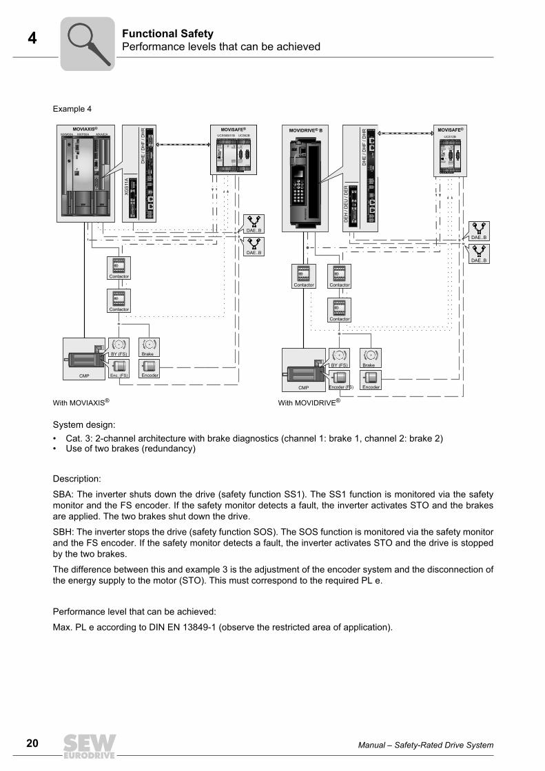
20
4 erformance levels that can be achievedunctional Safety
Example 4
With MOVIAXIS® With MOVIDRIVE®
System design:• Cat. 3: 2-channel architecture with brake diagnostics (channel 1: brake 1, channel 2: brake 2)• Use of two brakes (redundancy)
Description:
SBA: The inverter shuts down the drive (safety function SS1). The SS1 function is monitored via the safetymonitor and the FS encoder. If the safety monitor detects a fault, the inverter activates STO and the brakesare applied. The two brakes shut down the drive.
SBH: The inverter stops the drive (safety function SOS). The SOS function is monitored via the safety monitorand the FS encoder. If the safety monitor detects a fault, the inverter activates STO and the drive is stoppedby the two brakes.
The difference between this and example 3 is the adjustment of the encoder system and the disconnection ofthe energy supply to the motor (STO). This must correspond to the required PL e.
Performance level that can be achieved:
Max. PL e according to DIN EN 13849-1 (observe the restricted area of application).
X12
Power
1 0
SBUS
C E
1 2 3 4
S1S2
1 2
EURODRIVE
S3
S4
0
3
98
76 5
4
21
0
3
98
76 5
4
21
EURODRIVE
X12
16
59
16
59
X13
19
815
MO
VIA
XIS®
MO
VIA
XIS®
MO
VIA
XIS®
1234567891011
12345
MXA82A MXP80A MXM80A MOVIAXIS®
DH
E /
DH
F / D
HR
S2
L14
L13
L16
L15
L18
L17
ON
20
27
12
34
5
X30P
X30D
16
59
L12
L11X38
H L
T
DHF41B
X34
X35
X36
X37
XM
X32
X33
X31
L10
L9
L8
L7
T1
L6
L5
L4
L3
L2
L1
S1
UCS50B/51B UCS62B
UCS62B
DI 05 06 07 08
DI 09 10 11 12
DI 01 02 03 04
X8
X36X46
X16X26
X17
X7
16
59
STATUS
X33X43
X12 X13X23
X41X31
X21X11
STATUSPSU
DI 01 02 03 04
UCS50B
DI 09 10 11 12
DI 05 06 07 08
DI 13 14 P1 P2
X6
DO K1 K2 02 03
ENTER
MOVISAFE®
UCS50B/51B UCS62B
UCS62B
DI 05 06 07 08
DI 09 10 11 12
DI 01 02 03 04
X8
X36X46
X16X26
X17
X7
16
59
STATUS
X33X43
X12 X13X23
X41X31
X21X11
STATUSPSU
DI 01 02 03 04
UCS50B
DI 09 10 11 12
DI 05 06 07 08
DI 13 14 P1 P2
X6
DO K1 K2 02 03
ENTER
MOVISAFE®
CMP
XG
S11
A
X64
X62
X61
XGS11A
19
815
16
59
12
34
5
DAE..B
DAE..B
I0
I0
Brake
Contactor
Contactor
BY (FS)
Enc. (FS) Encoder
MOVIDRIVE® B
EURODRIVE
MO
VID
RIV
E®
DH
E /
DH
F / D
HR
X30-1
X30-2
L14
L13
X38
L12
L11H
L
T
DHF41B
2201
ON
X34
X35
X36
X37
XM
X32
X33
X31
L10
L9
L8
L7
T1
L6
L5
L4
L3
L2
L1
S1
CMP
BY (FS) Brake
DE
H /
DE
U /
DE
RX1
5X6
2
DEH21B
19
815
16
59
1 2
DAE..B
DAE..B
I0
I0
I0
UCS12B
UCS12B
X6
DI 01 02 03 04
DO K1 K2 02 03 DI 05 06 07 08
DI 09 10 11 12
ENTER
STATUS
DI 13 14 P1 P2
X7
X8
X31X41
X32X42
X11X21
X12X22
X13
16
59
16
59
MOVISAFE®
Encoder (FS) Encoder
Contactor
Contactor
Contactor
PF
Manual – Safety-Rated Drive System

4Differences between BY and BY(FS) brakesFunctional Safety
4.3 Differences between BY and BY(FS) brakesThe most important differences between the technical properties of the standard BY..brake and the safety-rated BY..(FS) brake are listed below.
All the other components such as the gear unit type, suitable ratio i, service factor fB,load change, output shaft, etc. must be selected and evaluated by the customer.
BY.. standard brake BY..(FS) FS brake
Brake type All All
Field of applicationHolding brakeWorking brake
YesYes
Yes (with emergency switching off properties) No
Ambient temperature-20 °C – +40 °COther ambient temperatures
YesYes
YesNo
Braking torques All Restrictions depending on the mounting position
Brake optionsManual brake release All HF not permitted
HR cannot be retrofitted
Maintenance of the driveCustomerSEW-EURODRIVE
YesYes
NoYes
Motor typeCMP. motors All CMPZ motors Approved are
CMPZ71, CMPZ80, CMPZ100
Motor optionsKYTF/Z
YesYes (special design)Yes
Must be usedNoYes
Speed class6000 rpm Yes No
EncoderAll Approved are
• RH1M• EK1H• AK1H• AK1H(FS)
Gear unit combination with Pinion bore/pinion shaft end
All Restriction of the permitted braking torques
Gear unitsRM.., R.07, R.17WT.., W..10, W..20, W..30PS.CHollow shaft with shrink diskTorqLOC®
Gear unit adapter
YesYesYesYesYesYes
NoNoNoRestriction of the permitted braking torquesNoNo
Special designs Yes No (upon request to SEW-EURODRIVE)
Mounting position All Restriction of the permitted braking torques
SEW measures Standard • Additional assembly steps• Additional documentation• Traceability up to batch monitoring• Manipulation protection at critical points
Category B 1
B10d value StandardSpecification per size
Higher values than the standardSpecification per size
Manual – Safety-Rated Drive System
21
22
5 otoromponents
5 Components5.1 Motor
In systems with safety-rated components, CMPZ motors can be used in sizes 71 – 100and speed classes 2000, 3000 and 4500.
5.2 Gear unitsThe versatile R..7, F..7, K..7, S..7, BSF, PSF and SPIROPLAN® W37/W47 series stan-dard gear units can be used.
When mounting these gear units to a CMP motor with a safety-rated brake, note thatcertain types might be excluded from use.
The following gear units may not be used on CMPZ motors with safety-rated brakes:
• RM.., R07, R17
• W..10, W..20, W..30
• PS.C
• Variable-speed gear unit
• Gear unit with TorqLOC®
• /AL, /AM, /AQ., /EHW adapters
Limitations apply when using gear units with shrink disk on the output shaft with safety-rated brakes as this is a frictional connection. If you still want to use these gear units,consult SEW-EURODRIVE in advance.
MC
Pi
fkVA
Hz
n
Manual – Safety-Rated Drive System

5BrakeComponents
5.3 Brake5.3.1 Principles of the SEW brakeBasic design
The SEW brake is an electromagnetic disk brake with a DC coil that releases electricallyand brakes using spring force. The system meets all fundamental safety requirements:The brake is applied automatically if the power fails.
The principal parts of the brake system are the brake coil itself [8] (BS accelerator coil +TS coil section = holding coil), comprising the magnet [9] with an encapsulated windingand a tap, the moving pressure plate [6], the brake springs [7], the brake disk [1] and thebrake endshield [2].
Basic functions
The pressure plate is forced against the brake disk by the brake springs when the elec-tromagnet is deenergized. The brake is applied to the motor. The number and type ofbrake springs determine the braking torque. When the brake coil is connected to the cor-responding DC voltage, the force of the brake springs [4] is overcome by magnetic force[11], thereby bringing the pressure plate into contact with the magnet. The brake diskmoves clear and the rotor can turn.
3985157259
[1] Brake disk [2] Brake endshield [3] Driver [4] Spring force[5] Working air gap[6] Pressure plate
[7] Brake spring [8] Brake coil[9] Magnet[10] Motor shaft[11] Electromagnetic force
[5]
[11]
[10]
[9]
[8]
[7]
[6]
[3]
[2]
[1]
[4]
Manual – Safety-Rated Drive System
Pi
fkVA
Hz
n
23

24
5 rakeomponents
5.3.2 Special features of FS brakes
There are a few differences between safety-rated brakes and non-safety-rated brakes.You can find these differences in a table in the “Differences between BY.. and BY..(FS)”(page 21) section.
Manual brake release
In brakemotors with the /HR option “Manual brake release with automatic reengagingfunction,” you can release the brake manually using the provided lever. The followingtable specifies the actuation force required at maximum braking torque to release thebrake by hand. The values are based on the assumption that you operate the lever atthe upper end.
Brake type Motor size Actuation forceFH in N
BY2 CMPZ71 50
BY4 CMPZ80 70
BY8 CMPZ100 90FH
BC
Pi
fkVA
Hz
n
Manual – Safety-Rated Drive System
5Safety-rated encodersComponents
5.4 Safety-rated encoders
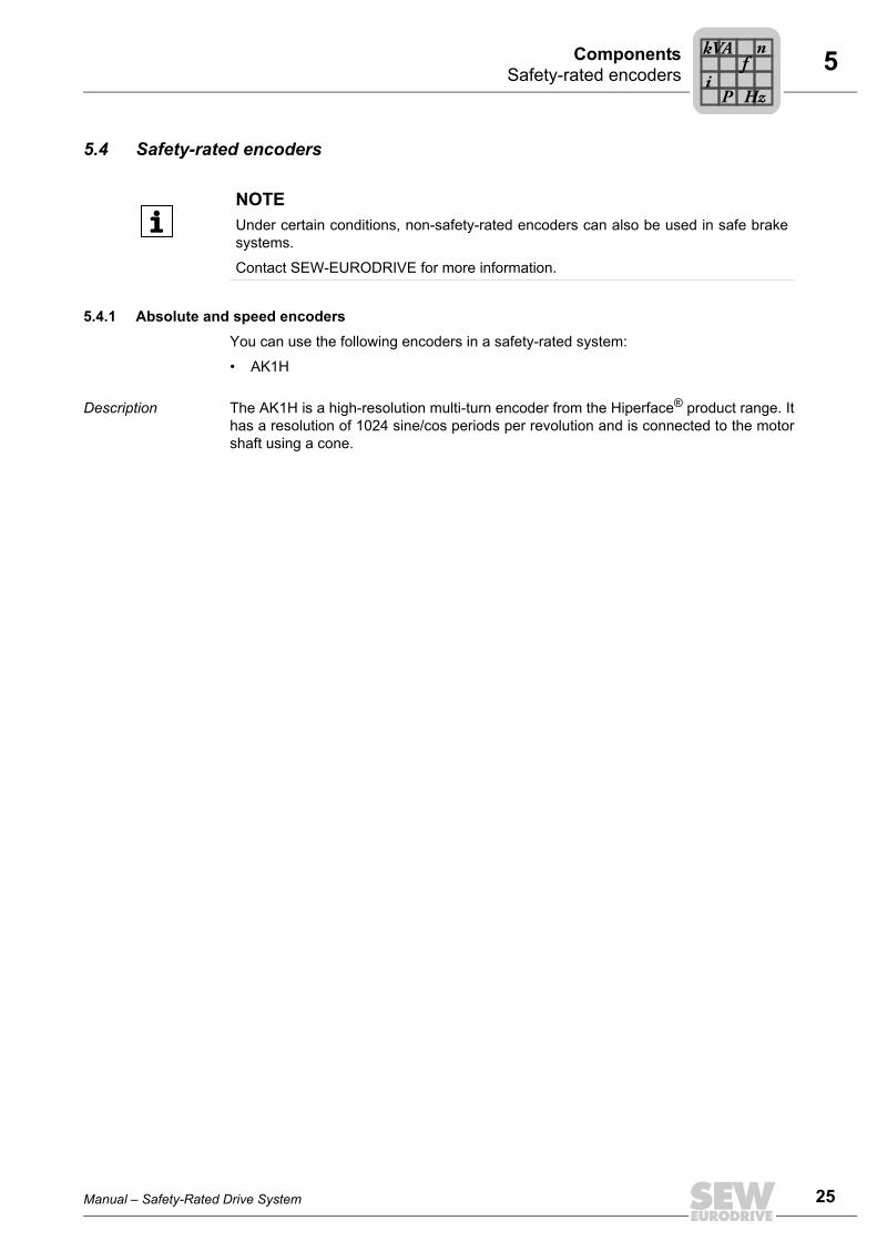
5.4.1 Absolute and speed encodersYou can use the following encoders in a safety-rated system:
• AK1H
Description The AK1H is a high-resolution multi-turn encoder from the Hiperface® product range. Ithas a resolution of 1024 sine/cos periods per revolution and is connected to the motorshaft using a cone.
NOTEUnder certain conditions, non-safety-rated encoders can also be used in safe brakesystems.
Contact SEW-EURODRIVE for more information.
Manual – Safety-Rated Drive System
Pi
fkVA
Hz
n
25

26
5 afety-rated brake controlomponents
5.5 Safety-rated brake controlIf the BY..(FS) brake is used in safety-related applications, then brake control must betaken into consideration in the safety evaluation.
Various brake controllers are available for controlling disk brakes with a DC coil,depending on the requirements and the operating conditions. All brake control systemsare fitted as standard with varistors to protect against overvoltage.
5.5.1 Safety-related BST brake moduleThe safety-related BST brake module safely disconnects the energy supply to the brake.
The BST brake module offers the following safety function:
• SBC (safe brake control), up to PL d according to EN ISO 13849
The BST brake module offers many advantages compared to conventional technology:
• Less space required in the control cabinet (no contactor and no motor protectionswitch)
• Improved energy balance (energy efficient as the regenerative energy from the DClink can be used)
• Reduced wiring work
• Easy installation
• Easy safety assessment
• No wear
Integrated Safety Technology
The safety technology of the safety-related BST brake module described in this docu-ment has been developed and tested in accordance with the following safety require-ments:
• Category 3 according to EN 954-1
• Performance level d according to EN ISO 13849-1
This was certified by TÜV Nord. A copy of the TÜV certificate can be obtained fromSEW-EURODRIVE.
Safe condition Safety-relevant use of the BST brake module means the de-energized condition ofthe connected brake is defined as safe condition. This is the basis of the safetyconcept.
NOTEUnder certain conditions, non-safety-rated brake controls can also be used in safebrake systems.
Contact SEW-EURODRIVE for more information.
SC
Pi
fkVA
Hz
n
Manual – Safety-Rated Drive System

5Safety-rated brake controComponents
Safety concept • The safety-related BST brake module enables the connection of an external fail-safesafety switching device/safety controller. The safety switching device disconnectsthe safe control voltage V24 V safe when a connected control device (e.g. emergencystop device) is activated.
• Disconnecting the safe control voltage V24 V safe means the connected brake isdisconnected from the power supply. The power supply required for releasing theconnected brake is interrupted safely.
• Instead of separating the brake control galvanically from the power supply using con-tactors or switches, the disconnection procedure described here prevents the powersemiconductors in the safety-related BST brake module from being activated, in thisway ensuring safe disconnection. This means that all connected brakes are de-en-ergized although the supply voltage is still present at the safety-related BST brakemodule.
Safety function The following drive-related safety function can be used:
• SBC (Safe Brake Control according to IEC 61800-5-2)
The SBC function safely de-energizes the connected brake by disconnecting thesafety-related control voltage V24 V safe. The safety-related control voltage must bedisconnected using a suitable external safety switching device/safety controller.
INFORMATIONSafety-related brake control must be carried out using the safety-related controlvoltage V24 V safe (terminal 5/6) only.
Manual – Safety-Rated Drive System
lP
if
kVA
Hz
n
27

28
5 afety-rated brake controlomponents
Approved unit combinations
The following BST unit types are permitted for safety-related applications:
The BST units are connected directly to the frequency inverters’ DC link.
• MOVIDRIVE® B: Can be connected directly to the terminals of the DC link.
• MOVIAXIS®: The BST can be connected to the DC link using the BST connection set(in preparation). See the addendum to the operating instructions for more informa-tion.
Technical data: safety-related con-trol voltage
The following table shows the technical data for safety-related control voltage V24 V safeat terminals 5/6:
Type designation Part number Approved SEW disk brakes
BST 0.6S-460V-00 0 829 971 4 All brake coils with a coil voltage of AC 460 V and a coil power ≤ 120 W.Several brake coils can be connected for redundant systems. In this case, the total power must not exceed 120 W.
BST 0.7S-400V-00 1 300 077 2 All brake coils with a coil voltage of AC 400 V and a coil power ≤ 120 W.Several brake coils can be connected for redundant systems. In this case, the total power must not exceed 120 W.
BST 1.2S-230V-00 1 300 133 7 All brake coils with a coil voltage of AC 230 V and a coil power ≤ 120 W.Several brake coils can be connected for redundant systems. In this case, the total power must not exceed 120 W.
Safety-related control voltage V24 V safe Min. Typical Max.
Input voltage rangeaccording to DIN EN 61131-2 DC 24 V
DC 20.4 V DC 24 V DC 28.8 V
Input current 50 mA
Input capacitance 4.7 μF 6 μF
Switch-on/switch-off threshold DC 10 V
Input voltage for OFF state(brake de-energized) DC 6 V
Duration from switching off the safety-related control voltage at BST until switching off the brake voltage VB plus the brake application time of the connected brake.1)
1) The brake application time for cut-off in the AC circuit must be used.
6 ms
Safety-related control cable
• Cable length 100 m (328 ft)
• Cable cross section 0.5 mm2 (AWG 20)
1.5 mm2 (AWG 16)
SC
Pi
fkVA
Hz
n
Manual – Safety-Rated Drive System

5Frequency invertersComponents
5.6 Frequency invertersAn extensive product range of SEW-EURODRIVE frequency inverters is available forelectronically controlled drives. SEW-EURODRIVE recommends the following inverterseries for safety-related drive systems:
• MOVIDRIVE® B: High-performance drive inverter for dynamic drives in the powerrange 0.55 – 250 kW. Great diversity of applications due to extensive expansionoptions with technology and communication options. Three-phase supply systemconnection for AC 230 V and AC 400 – 500 V.
• MOVIAXIS®: High-performance, versatile multi-axis servo inverter with axis modulenominal currents from 2 – 133 A. Wide variety of applications due to extensiveexpansion options with technology and communication options, as well as optionalsinusoidal regenerative power supply. Three-phase line connection for AC 380 –500 V.
Manual – Safety-Rated Drive System
Pi
fkVA
Hz
n
29
30
5 EW controlleromponents
5.7 SEW controller 5.7.1 MOVI-PLC®
The MOVI-PLC® controller runs on the universally parameterizable MultiMotion soft-ware platform from SEW-EURODRIVE. The platform provides comprehensive motioncontrol functions, in particular for technology functions, such as:
• Positioning
• Electronic gear unit / synchronous operation
• Cams
• Interpolation
• Touch probe function
• Cam controller
The MOVI-PLC® control software is programmed using the PLC Editor.
5.7.2 CCU (Configurable Control Unit)Control technology from SEW-EURODRIVE includes the configurable control unit(CCU) for easily configurable applications with standardized and immediately execut-able application modules, which merely have to be parameterized. The functions matchthe specific application and can be configured easily and quickly without any program-ming knowledge. An integrated diagnostic function helps to speed up and facilitatestartup.
The platform provides comprehensive motion control functions, in particular for technol-ogy functions, such as:
• Positioning
• Synchronous operation
• Touch probe function
• Winding
• Robot kinematics
• Flying saw, rotating knife
• Energy efficient storage/retrieval system
SC
Pi
fkVA
Hz
n
Manual – Safety-Rated Drive System

5MOVISAFE® UCS..B safety moduleComponents
5.8 MOVISAFE® UCS..B safety moduleThe MOVISAFE® UCS..B product series comprises modular, programmable safety con-trollers for implementing safe disconnection and drive monitoring functions (velocity andposition monitoring). The safety controllers are designed for installation in the controlcabinet.
The modular design of the UCS..B safety controllers makes it possible to adjust thesafety-relevant functionality to the specific application. Two module series are available:
• Safety controllers UCS..B Compact for separate monitoring of up to 2 axes, consist-ing of
– Basic module with integrated logic, inputs and outputs as well as up to 2 encoderinterfaces
– Optional function expansion with PROFIsafe interface/PS for connection to ahigher-level safety controller
– Optional expansion module with additional inputs and outputs
– Optional expansion module with PROFIBUS or PROFINET interface for connec-tion to a higher-level controller.
• Safety controllers UCS..B Multi-axis for monitoring up to 12 axes, consisting of
– Basic module with integrated logic as well as inputs and outputs (optionally avail-able with integrated PROFIBUS, PROFINET interface for connection to a higher-level controller)
– Optional axis expansion module with 1 or 2 encoder interfaces
– Optional expansion module with additional inputs and outputs
Manual – Safety-Rated Drive System
Pi
fkVA
Hz
n
31

32
5 refabricated cablesomponents
5.9 Prefabricated cablesSEW-EURODRIVE offers prefabricated cables with plugs for straightforward and reli-able motor connection.
Cable and contact are connected using the crimp technique. Cables are available by themeter.
Prefabricated cables are divided into:
• Power cables (motor cable, brakemotor cable, extension cable)
• Feedback cables (encoder cable, extension cable).
5.9.1 Preselection of cablesPrefabricated cables were preselected by SEW-EURODRIVE according to the standardEN 60204. The routing types "fixed installation" and "cable carrier installation" were con-sidered.
Using other standards for the machine construction can result in diverging cross sec-tions.
PC
Pi
fkVA
Hz
n
Manual – Safety-Rated Drive System

5Additional documentationComponents
5.10 Additional documentationThe following table provides an overview of additional documentation for the individualcomponents.
You can order these publications from SEW-EURODRIVE.
Motors
Operating instructions: “CMP Synchronous Servomotors”
Catalog: “Synchronous Servomotors”
Gear units
Operating instructions: "Gear Units R..7, F..7, K..7, S..7, and SPIROPLAN® W"
Catalog: "Asynchronous Servo Gearmotors: DRL71 – 225 Servomotors with R, F, K, S, W Gear Units"
Brake
Drive Engineering - Practical Implementation: "SEW Disk Brakes"
Addendum to the operating instructions: “Safety-Rated Brakes; Functional Safety for CMP Synchro-nous Servomotors”
Data sheet: “Safety Characteristics of BY..(FS) Brakes”
Encoder
Drive Engineering - Practical Implementation: "SEW Encoder Systems"
Addendum to the operating instructions: “Safety-Rated Encoders; Functional Safety for CMP Synchro-nous Servomotors”
Data sheet: “Functional Safety for CMP Synchronous Servomotors.; Safety-Rated Encoder AK1H”
Brake rectifier
Operating instructions: "Safety-related BST brake module"
Data sheet: "Functional safety: Safety Characteristics for Safety-Related Brake Module BST"
Frequency inverters
Operating instructions: "MOVIDRIVE® MDX60B/61B"
Catalog:® "MOVIDRIVE® MDX60B/61B"
Manual: "MOVIDRIVE® MDX60B/61B – Functional Safety"
System manual: "MOVIDRIVE® MDX60B/61B"
Data sheet: "Functional Safety; Safety Characteristics MOVIDRIVE® MDX60B/61B"
Operating instructions: “MOVIAXIS® Multi-Axis Servo Inverters”
Addendum to the Operating Instructions: “MOVIAXIS® Multi-Axis Servo Inverters, BST Connection Set”
System manual: “MOVIAXIS® Multi-Axis Servo Inverters”
Data sheet: “Functional Safety; Safety Characteristics MOVIAXIS® MXA81A”
Data sheet: “Functional Safety; Safety Characteristics MOVIAXIS® MXA82A”
SEW Controller
Manual: "MultiMotion for MOVI-PLC®"
Manual: “Controller – DHE21B / DHF21B / DHR21B, DHE41B / DHF41B / DHR41B”
Manual: “Configuration Software – Application Configurator for CCU”
MOVISAFE® UCS..B safety module
Operating instructions: "MOVISAFE® UCS.B Safety Modules"
Data sheet: "Functional Safety; Safety Characteristics MOVISAFE® UCS..B"
Manual – Safety-Rated Drive System
Pi
fkVA
Hz
n
33
34
6 roject planning procedure for BY..(FS) brakesroject Planning
6 Project Planning6.1 Project planning procedure for BY..(FS) brakes
The standard configuration is performed according to the catalog and is the basis for aconfiguration of the safety-rated brake on a (gear-) motor. This is expanded to includeadditional safety measures during configuration. The gear unit utilization is additionallytaken into consideration by the braking torque.
The following project planning notes are examples. They already include these addi-tional checks. It might be necessary to adapt the following project planning notes to thespecific application.
The project planning notes do not guarantee a safe drive or drive system. The safety-rated BY..(FS) brake is intended for use in functional safety applications. As a compo-nent, it is part of the drive system. The user must conclusively evaluate whether the drivesystem is suitable for functional safety.
Furthermore, there are limits in terms of the available combinations in connection with aBY..(FS) brake (e.g. no TorqLOC®). The limits are listed in an overview table in section“Differences between BY brakes and BY(FS) brakes” (page 21).
Key to the project planning procedure illustrations:
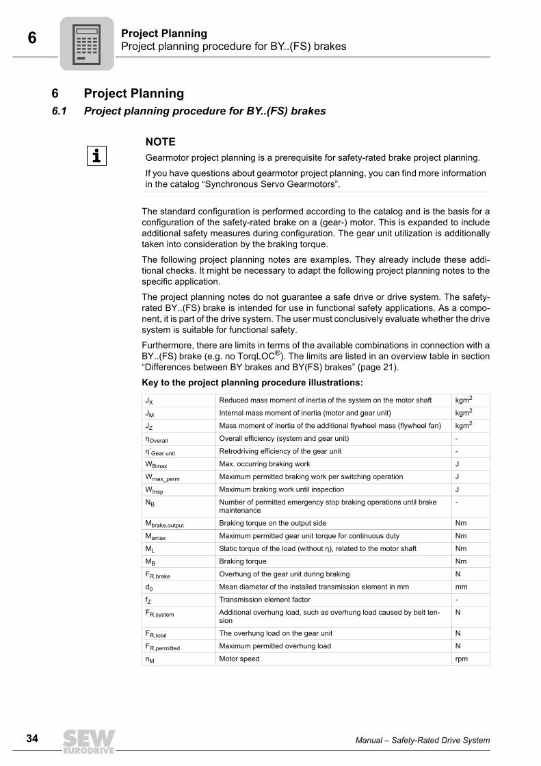
NOTEGearmotor project planning is a prerequisite for safety-rated brake project planning.
If you have questions about gearmotor project planning, you can find more informationin the catalog “Synchronous Servo Gearmotors”.
JX Reduced mass moment of inertia of the system on the motor shaft kgm2
JM Internal mass moment of inertia (motor and gear unit) kgm2
JZ Mass moment of inertia of the additional flywheel mass (flywheel fan) kgm2
ηOverall Overall efficiency (system and gear unit) -
η’Gear unit Retrodriving efficiency of the gear unit -
WBmax Max. occurring braking work J
Wmax_perm Maximum permitted braking work per switching operation J
WInsp Maximum braking work until inspection J
NB Number of permitted emergency stop braking operations until brake maintenance
-
Mbrake,output Braking torque on the output side Nm
Mamax Maximum permitted gear unit torque for continuous duty Nm
ML Static torque of the load (without η), related to the motor shaft Nm
MB Braking torque Nm
FR,brake Overhung of the gear unit during braking N
d0 Mean diameter of the installed transmission element in mm mm
fZ Transmission element factor -
FR,system Additional overhung load, such as overhung load caused by belt ten-sion
N
FR,total The overhung load on the gear unit N
FR,permitted Maximum permitted overhung load N
nM Motor speed rpm
PP
Manual – Safety-Rated Drive System

6Project planning procedure for BY..(FS) brakesProject Planning
6.1.1 Project planning procedure for the brake on a trolley
1) ML and η are application data and must be specified by the user
Note:For values for Wmax_perm, see chapter "Maximum permitted braking work for emergency switching off withBY..(FS) brakes"For values for Winsp, see chapter "Characteristic data of BY.. / BY..(FS) brakes"
Project planning procedure trolley
Required value reached?
No
Drivechange
W WBmax max_perm≤
1)
Configured driveCatalog data / system data
Calculation of maximum occurring braking work
Calculation of the number of permittedemergency braking stops until brake maintenance:
NBW
WInsp
B=
max
Yes
Yes
No
( ) 2
max 182.5M Z X MB
BL
B
J J J nMW
MM
η
η
+ +=
+
×××
Total
Total
Manual – Safety-Rated Drive System
35
36
6 roject planning procedure for BY..(FS) brakesroject Planning
2) ML and Jx are application data and must be specified by the user. η’gear is the efficiency of the gear unit for retrodriving torques. Information about determining these values can be found in the catalog “Synchronous Servo Gearmotors”.
3) Application torques may have to be taken into consideration.
Calculation of torque on the output side when braking:
No
Changedrive
Additional application-specificcriteria must be checked
M MBrake, drive ≤
F FR, total R, permitted≥
Calculation of the overhung of the gear unit during braking:
FM
dfR brake
brake,outputZ, =
2000
0
××
Yes
Yes
No
2)
3)
a_perm
( )1.51
X
M Z
X
M Z
JJ JJ
J J
+
++
][( )× −× × +M M MM B L LBrake, drive = i 1 ×ηGear units‚
PP
Manual – Safety-Rated Drive System

6Project planning procedure for BY..(FS) brakesProject Planning
6.1.2 Project planning procedure for the brake on a hoist
1) ML and η are application data and must be specified by the user2) The greater of the two values for upward and downward travel has to be checked.
Note:For values for Wmax_perm, see chapter "Maximum permitted braking work for emergency switching off withBY..(FS) brakes"For values for Winsp, see chapter "Characteristic data of BY.. / BY..(FS) brakes"
Project planning procedure hoist
Configured driveCatalog data / system dat
Calculation of maximum occurring braking work1)Calculation of maximum occurring braking work
W WBmax max_perm≤
Calculation of the number of permittedemergency braking stops until brake maintenance:
NBW
WInsp
B=
max
Required value reached?
Yes
No
Changedrive
No
2)
Upward travel Downward travel
1)
Yes
( ) 2
max 182.5M Z X MB
BL
B
J J J nMW
MM
η
η
+ +=
+
×××
Total
Total ( ) 2
max 182.5M Z X MB
B
LB
J J J nMW
MM
η
η
+ +=
−
×××
Total
Total
×
Manual – Safety-Rated Drive System
37
38
6 roject planning procedure for BY..(FS) brakesroject Planning
3) ML and Jx are application data and must be specified by the user. η’gear is the efficiency of the gear unit for retrodriving torques. Information about determining these values can be found in the catalog “Synchronous Servo Gearmotors”.
4) Application torques may have to be taken into consideration.
Upward travel
Downward travelChange drive
M MBrake, drive ≤ No
Additional application-specificcriteria must be checked
F FR total R permitted≥
Calculation of the overhung of the gear unit during braking:
FM
dfbrake, outputZR, brake =
2000
0
××
Yes
Yes
No4)
Calculation of torque on the output side when braking3)
Calculation of torque on the output side when braking:3)
a_perm
( )1.51
X
M Z
X
M Z
JJ JJ
J J
+
++
][( )× −× × +M M MM B L LBrake, drive = i 1 ×ηGear units‚
( )1,.1
X
M Z
X
M Z
JJ JJ
J J
+
++
][( )× +× × −M M MM B L LBrake, drive = i 1 ×ηGear units‚
PP
Manual – Safety-Rated Drive System
6Brake BY..(FS)Project Planning
6.2 Brake BY..(FS)6.2.1 General information
The BY..(FS) working brake can only be mounted on CMPZ71 – CMPZ100 motors (mo-tor design with additional flywheel mass).
The size of the brakemotor and its electrical connection must be selected carefully toensure the longest possible service life.
The following aspects described in detail must be taken into account:
1. Selecting the braking torque in accordance with the project planning data.
2. Dimensioning and routing of the cable.
3. Selecting the brake contactor, if applicable.
4. Important design information.
6.2.2 Selecting the brake in accordance with the project planning dataThe mechanical components, brake type and braking torque, are determined when thedrive motor is selected. The drive type or application areas and the standards that haveto be taken into account are used for the brake selection.
Selection criteria:
• Servomotor motor size.
• Number of emergency-off braking operations.
• Level of braking torque (“soft braking”/“hard braking”).
• Hoist application
• Minimum/maximum deceleration
• Encoder system used
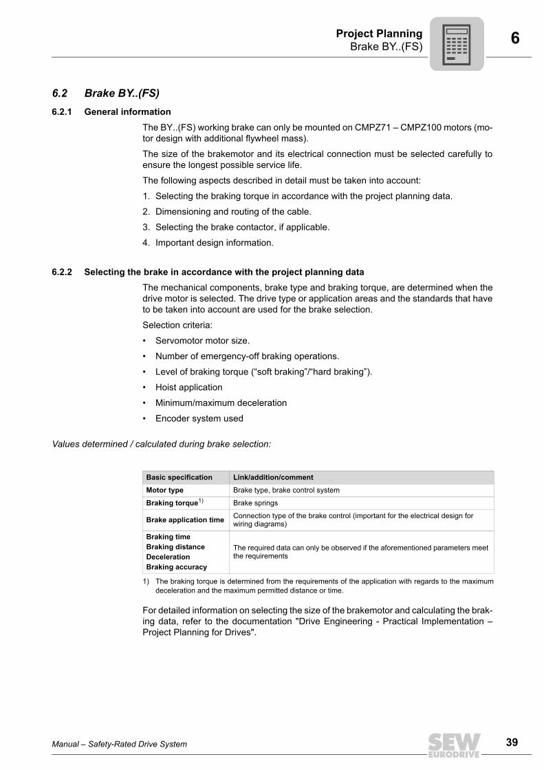
Values determined / calculated during brake selection:
For detailed information on selecting the size of the brakemotor and calculating the brak-ing data, refer to the documentation "Drive Engineering - Practical Implementation –Project Planning for Drives".
Basic specification Link/addition/comment
Motor type Brake type, brake control system
Braking torque1)
1) The braking torque is determined from the requirements of the application with regards to the maximumdeceleration and the maximum permitted distance or time.
Brake springs
Brake application time Connection type of the brake control (important for the electrical design for wiring diagrams)
Braking timeBraking distanceDecelerationBraking accuracy
The required data can only be observed if the aforementioned parameters meet the requirements
Manual – Safety-Rated Drive System
39
40
6 rake BY..(FS)roject Planning
Selecting the brake
The brake suitable for the relevant application is selected by means of the following maincriteria:
• Required braking torque
• Required working capacity
Braking torque The braking torque is usually selected according to the required deceleration.
Possible braking torque gradation can be found in the section “Technical Data of the BYBrake” in the “Synchronous Servomotors” catalog.
Braking torque in hoist applications
Working capacity The working capacity of the brake is determined by the permitted braking work done W1per braking operation and the total permitted braking work Winsp until maintenance ofthe brake.
The overall permitted braking work Winsp can be found in the section “Technical Data ofthe BY Brake” in the “Synchronous Servomotors” catalog.
Permitted number of braking operations until maintenance of the brake:
Braking work per braking operation:
NOTEThe selected braking torque must be greater than the maximum load torque by at leastfactor 2.
NB = Number of braking operations until service
Winsp = Total braking work until service in J
W1 = Braking work per braking operation in J
Jges = Total mass moment of inertia (related to the motor shaft) in kgm2
n = Motor speed rpm]
MB = Braking torque in Nm
ML = Load torque in Nm (observe the +/- character)+: for vertical upward and horizontal movement-: for vertical downward movement
NB = Winsp
W1
W1 = Jges n2 MB
182.4 (MB - ML)+
x x
x
BP
Manual – Safety-Rated Drive System

6Brake BY..(FS)Project Planning
Emergency stop features
The limits of the permitted maximum braking work must not be exceeded, not even foremergency switch-off.
The emergency switch-off properties must therefore be based on the directions of move-ment.
1. Braking during vertical movementIn hoist applications, the limits of the permitted maximum braking work (includingemergency stops) may not be exceeded.
Please consult SEW-EURODRIVE if you need values for increased emergencyswitch-off braking work in hoist applications.
2. Braking during horizontal movementFor horizontal motion like in travel drive applications, higher braking work might bepermitted per cycle in emergency stop situation under the following conditions A - D.
A Selected braking torque
All braking torques are permitted. In contrast to BE brakes, with BY brakes, youdon’t have to select a braking torque that is reduced by at least one stage in termsof the brake size when using them with DR motors.
B Brake wear
The specific wear of the brake lining increases significantly in case of an emer-gency stop. It can reach a factor of 100 under certain circumstances.
This additional wear must be taken into account when determining the mainte-nance cycle.
C Braking process
During the braking process, the effective dynamic braking torque can be reduceddue to the heating of the brake lining during braking. In extreme cases, the effec-tive braking torque can be reduced to 60% of the rated value. This must be notedwhen determining the braking distance.
Example: BY8 with MB = 80 Nm, minimal effective MB = 48 Nm
D Braking speed
A decisive factor for the permitted increased braking work is the speed at whichthe braking process is triggered. The lower the speed, the higher the permittedbraking work.
Please consult SEW-EURODRIVE if you need values for increased emergencyswitch-off braking work in travel drive applications.
3. Braking during inclined upwards movementBecause inclined upward movement has a vertical and a horizontal component, thepermitted emergency stop braking work is predominantly determined according topoint 1.
Please contact SEW-EURODRIVE if you are unable to classify the direction of mo-tion as solely vertical or solely horizontal.
Manual – Safety-Rated Drive System
41
42
6 rake BY..(FS)roject Planning
6.2.3 No-load starting frequency
The following no-load starting frequency Z0 must not be exceeded in order to preventthe BY brake from heating up.
6.2.4 Determining the brake voltageThe brake voltage should always be selected on the basis of the available AC supplyvoltage or motor operating voltage. This means the user is always guaranteed the mostcost-effective installation for lower braking currents.
The standard brake voltages are listed in the following table:
When releasing the brake, the holding current can increase by up to 7 times. The voltageat the brake coil may not drop below 90% of the rated voltage.
6.2.5 Selecting the brake control systemOnly SEW brake control systems are used for controlling the brake. All brake controlsystems are fitted as standard with varistors to protect against overvoltage.
The brakes are available with DC and AC voltage connection.
• AC voltage connection:
– BME, equipped with DIN rail profile
• DC voltage connection:
– BSG.
Two types of electrical cut-off are available:
• Normal application times: cut-off in the AC circuit.
• Particularly short application times: cut-off in the AC and DC circuits.
The brake control systems are mounted in the control cabinet. Retaining screws are in-cluded in the scope of delivery.
Brake No-load starting frequency
BY2 7200 1/h
BY4 7200 1/h
BY8 7200 1/h
Brake BY2, BY4, BY8Brake voltage
Rated voltage1)
1) The 24 V brake voltage requires a strong current and is only possible with limited cable length.
DC 24 VAC 110 VAC 230 VAC 400 VAC 460 V
BP
Manual – Safety-Rated Drive System

6Brake BY..(FS)Project Planning
The following options are available:
• AC supply, cut-off in the AC and DC circuits without additional switch contact, partic-ularly short application times: BMP.
• AC supply, brake heating function when switched off: BMH.
• The BMK/BMKB/BMV control system energizes the brake coil if the supply systemand a DC 24 V signal (e.g. from the PLC) are present simultaneously. The brake isapplied if one condition is not being met. BMK/BMKB/BMV allow for shortest re-sponse and application times.
• Safe brake control up to PL d, supply via DC link: BST
The following table lists SEW brake control systems for installation in the control cabinet.The different housings have different colors (= color code) to make them easier to dis-tinguish.
NOTEFor emergency switch-off and emergency stop and for hoists in general, a disconnec-tion of all poles is required (terminal 1 and 2 of the brake rectifier).
Brake control Function Voltage Holding cur-rent IHmax (A) type Part number Color code
BME One-way rectifier with electronic switching
AC 150 – 500 V 1.5 BME 1.5 825 722 1 RedAC 42 – 150 V 3.0 BME 3 825 723 X Blue
BMH One-way rectifier with electronic switching and heating function
AC 150 – 500 V 1.5 BMH 1.5 825 818 X GreenAC 42 – 150 V 3 BMH 3 825 819 8 Yellow
BMPOne-way rectifier with electronic switching, integrated voltage relay for cut-off in the DC circuit
AC 150 – 500 V 1.5 BMP 1.5 825 685 3 White
AC 42 – 150 V 3.0 BMP 3 826 566 6 Light blue
BMKOne-way rectifier with electronic switching, DC 24 V control input and cut-off in the DC circuit
AC 150 – 500 V 1.5 BMK 1.5 826 463 5 Water blue
AC 42 – 150 V 3.0 BMK 3 826 567 4 Bright red
BMKBOne-way rectifier with electronic switch mode, DC 24 V control input, cut-off in the DC circuit and a diode to signal the readiness for operation
AC 150 – 500 V 1.5 BMKB 1.5 828 160 2 Water blue
BSG Control unit for DC 24 V connection with electronic switching DC 24 V 5.0 BSG 825 459 1 White
BMV Electric switching, DC 24 V control input and cut-off in the DC circuit DC 24 V 5.0 BMV 1 300 006 3 White
Manual – Safety-Rated Drive System
43
44
6 rake BY..(FS)roject Planning
Quick reaction times
A particular feature of the SEW brake is its patented two coil system. This system con-sists of accelerator coil and coil section. The special SEW brake control system ensuresthat the accelerator coil is switched on with a high current inrush when the brake is re-leased, after which the coil section is switched on. The result is a particularly short re-sponse time when releasing the brake. The brake disk moves clear very swiftly and themotor starts up with hardly any brake friction.
This principle of the two coil system also reduces self-induction so that the brake is ap-plied more rapidly. The result is a reduced braking distance. The SEW brake can be cutoff in the DC and AC circuits to achieve particularly short response times when applyingthe brake, for example for hoists.
6.2.6 Dimensioning and routing the cable for terminal boxesa) Selecting the cable
Select the cross section of the brake cable according to the currents in your application.Observe the inrush current of the brake when selecting the cross section. When takingthe voltage drop into account due to the inrush current, the value must not drop below90 % of the rated voltage. The data sheets for the brakes provide information on the pos-sible supply voltages and the resulting operating currents.
Information about the size of the cable cross-section and the cable lengths can be foundin the “Cable Classifications” tables in the “Synchronous Servomotors” catalog.
Wire cross sections of max. 2.5 mm2 can be connected to the terminals of thebrake control systems. Intermediate terminals must be used if the cross sectionsare larger.
b) Routing information
Brake cables must always be routed separately from other power cables withphased currents unless they are shielded. Ensure adequate equipotential bonding between the drive and the control cabinet(for an example, see the documentation Drive Engineering – Practical Implemen-tation "EMC in Drive Engineering").Power cables with phased currents are in particular• Output cables from frequency inverters and servo inverters, soft start units and brake
units
• Supply cables to braking resistors
BP
Manual – Safety-Rated Drive System

6Brake BY..(FS)Project Planning
6.2.7 Selection of the brake contactor
Due to the high current loading and the DC voltage to be switched at inductive load, con-tactors in utilization category AC 3 (EN 60947-4-1) must always be used for controllingthe brake rectifiers.
For brake control via BSG and BMV, contactors in utilization category DC 3 must beused (EN 60947-4-1).
Standard variant
The CMPZ brakemotors with BME for are delivered without additional order informationfor AC connection.
Switching via con-tactor
Control via inverter
6.2.8 Important design informationa) EMC (electromagnetic compatibility)
The EMC instructions in the servo inverter documentation must also be taken into ac-count for the operation of SEW servomotors with a brake.
The instructions on laying cables must always be adhered to.
b) Maintenance intervals
The time to maintenance is determined on the basis of the expected brake wear. Thisvalue is important for setting up the maintenance schedule for the machine to be usedby the customer’s service personnel (machine documentation).
Brake size AC connection DC 24 V connection
BY2
BME BSGBY4
BY8
Brake size AC connection DC 24 V connection
BY2
BMK BMVBY4
BY8
Manual – Safety-Rated Drive System
45
46
7 echnical data of BY brakesechnical Data
7 Technical Data7.1 Technical data of BY brakes
The following tables list the technical data of the brakes. The type and number of brakesprings determines the level of the braking torque. Unless specified otherwise in theorder, maximum braking torque MB max is installed as standard. Other brake spring com-binations can produce the reduced braking torque values MB red.
7.1.1 Motor assignmentThe BY brake can be used for the following rated speeds and braking torques dependingon the motor size:
Brake type MB maxNm
MB redNm
Winsp103 kJ
PW
t1ms
t2ms
t3ms
BY2 20 10 35 27 25 23 130BY4 40 20 50 38 30 17 110BY8 80 40 60 45 55 25 210
MB max = Maximum braking torque
MB red = Optional braking torque
Winsp = Permitted total braking work (braking work until maintenance)
P = Power consumption of the coil
t1 = Response time
t2 = AC/DC application time
t3 = AC application time
NOTEThe response and application times are guide values that were determined at maxi-mum braking torque.
Possible response times of switching elements or controllers were not taken into ac-count.
Motor type Brake type MB1Nm
MB2Nm Speed class
CMPZ71SBY2
14 102000, 3000, 4500
CMPZ71M/L 20 14CMPZ80S
BY428 20
2000, 3000, 4500CMPZ80M/L 40 28CMPZ100S
BY855 40
2000, 3000, 4500CMPZ100M/L 80 55
MB1 Preferred braking torque
MB2 Optional braking torque
TT
Pi
fkVA
Hz
n
Manual – Safety-Rated Drive System

7Technical data of BY brakesTechnical Data
7.1.2 Maximum permitted friction work
The following table lists the permitted friction work from which the braking procedure istriggered, depending on the start speed. The lower the speed, the higher the permittedbraking work.
NOTEIf the motor is not stopped in a controlled manner with the inverter, but instead thebrake is used for mechanical deceleration: Check that the brake can provide the re-quired braking start speed in case of an emergency switching off situation.
Start speed Brake type MB maxW1
for all applications
W1Only trolley applications
rpm Nm kJ kJ
2000
BY2
7 20 40
10 18 36
14 15 30
20 12 24
BY4
14 24 48
20 19.5 39
28 17 34
40 10.5 21
BY8
28 48 96
40 44 88
55 32 64
80 18 36
3000
BY2
7 20 40
10 18 36
14 14 28
20 11 22
BY4
14 20 40
20 15 30
28 10 20
40 4.5 9
BY8
28 36 72
40 32 64
55 18 36
80 7 14
Table continued on next page.
Manual – Safety-Rated Drive System
Pi
fkVA
Hz
n
47

48
7 echnical data of BY brakesechnical Data
7.1.3 BY brake – operating currents The following tables list the operating currents of the brakes at different voltages. Thefollowing values are specified:
• Inrush current ratio IB/IH; IB = accelerator current, IH = holding current
• Holding current IH• Rated voltage VN
The acceleration current IB (= inrush current) only flows for a short time (ca. 120 ms)when the brake is released or during voltage dips below 70 % of rated voltage.
The values for the holding currents IH are rms values (with DC 24 V arithmetic meanvalue). Use suitable measuring instruments for current measurements.
4500
BY2
7 16 32
10 14 28
14 10 20
20 6 12
BY4
14 15 30
20 9 18
28 5 10
40 3 6
BY8
28 22 44
40 18 36
55 11 22
80 4 8
MB max = Maximum braking torque
W1 = Permitted braking work per cycle
Start speed Brake type MB maxW1
for all applications
W1Only trolley applications
rpm Nm kJ kJ
BY2 BY4 BY8
Maximum braking torque in Nm 20 40 80
Braking power in W 27 38 45
Inrush current ratio IB/IH or IB/IG 5 4 4
Rated voltage VN IHAAC
IDCADC
IHAAC
IDCADC
IHAAC
IDCADCVAC VDC
24(21.6 – 26.4)
– 1.05 – 1.4 – 1.6
110 (99 – 121) 0.425 – 0.58 – 0.69 –
230 (218 – 243) 0.19 – 0.26 – 0.305 –
400 (380 – 431) 0.107 – 0.147 – 0.172 –
460 (432 – 484) 0.095 – 0.131 – 0.154 –
IH Holding current, r.m.s. value in the incoming cable to the SEW brake rectifierIDC Direct current with direct DC voltage supplyVN Nominal voltage (nominal voltage range)
TT
Manual – Safety-Rated Drive System
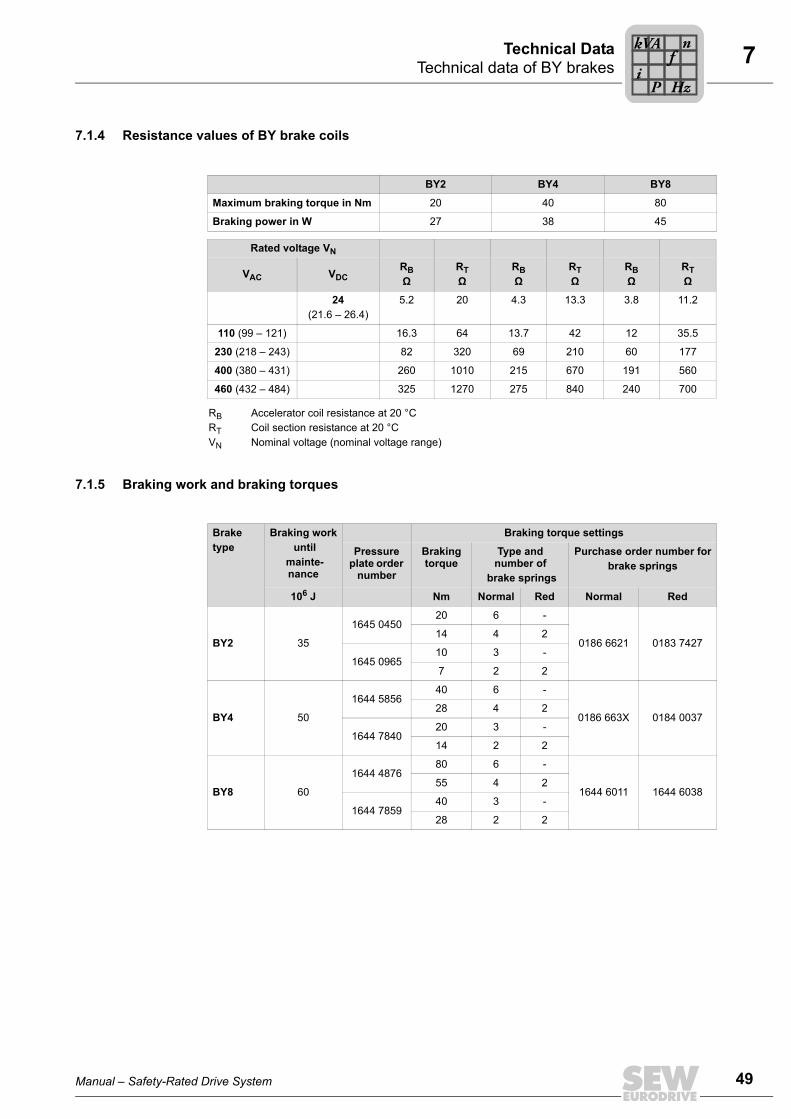
7Technical data of BY brakesTechnical Data
7.1.4 Resistance values of BY brake coils
7.1.5 Braking work and braking torques
BY2 BY4 BY8
Maximum braking torque in Nm 20 40 80
Braking power in W 27 38 45
Rated voltage VN
RBΩ
RTΩ
RBΩ
RTΩ
RBΩ
RTΩVAC VDC
24(21.6 – 26.4)
5.2 20 4.3 13.3 3.8 11.2
110 (99 – 121) 16.3 64 13.7 42 12 35.5
230 (218 – 243) 82 320 69 210 60 177
400 (380 – 431) 260 1010 215 670 191 560
460 (432 – 484) 325 1270 275 840 240 700
RB Accelerator coil resistance at 20 °CRT Coil section resistance at 20 °CVN Nominal voltage (nominal voltage range)
Braketype
Braking work until
mainte-nance
Braking torque settings
Pressure plate order
number
Braking torque
Type and number of
brake springs
Purchase order number forbrake springs
106 J Nm Normal Red Normal Red
BY2 35
1645 045020 6 -
0186 6621 0183 742714 4 2
1645 096510 3 -
7 2 2
BY4 50
1644 585640 6 -
0186 663X 0184 003728 4 2
1644 784020 3 -
14 2 2
BY8 60
1644 487680 6 -
1644 6011 1644 603855 4 2
1644 785940 3 -
28 2 2
Manual – Safety-Rated Drive System
Pi
fkVA
Hz
n
49

50
7 echnical data of BY brakesechnical Data
Depending on the mounting position V3 (brake on the bottom with manual brake re-lease), the gray braking torques in the following table are not available:
BrakeType
Braking work until
mainte-nance
Braking torque settings
Pressure plate order number
Braking torque
Type and number of brake springs
106 J Nm Normal Red
BY2 35
1645 045020 6 -
14 4 2
1645 096510 3 -
7 2 2
BY4 50
1644 585640 6 -
28 4 2
1644 784020 3 -
14 2 2
TT
Pi
fkVA
Hz
n
Manual – Safety-Rated Drive System
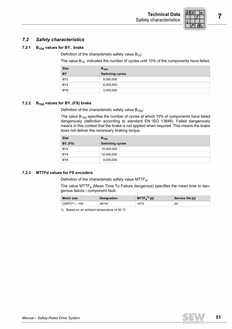
7Safety characteristicsTechnical Data
7.2 Safety characteristics7.2.1 B10d values for BY.. brake
Definition of the characteristic safety value B10:
The value B10 indicates the number of cycles until 10% of the components have failed.
7.2.2 B10d values for BY..(FS) brakeDefinition of the characteristic safety value B10d:
The value B10d specifies the number of cycles at which 10% of components have faileddangerously (definition according to standard EN ISO 13849). Failed dangerouslymeans in this context that the brake is not applied when required. This means the brakedoes not deliver the necessary braking torque.
7.2.3 MTTFd values for FS encodersDefinition of the characteristic safety value MTTFd:
The value MTTFd (Mean Time To Failure dangerous) specifies the mean time to dan-gerous failure / component fault.
Size B10d
BY Switching cycles
BY2 8,000,000
BY4 6,000,000
BY8 3,000,000
Size B10d
BY..(FS) Switching cycles
BY2 15,000,000
BY4 12,000,000
BY8 9,000,000
Motor size Designation MTTFd1) [a]
1) Based on an ambient temperature of 40 °C
Service life [a]
CMPZ71 – 100 AK1H 1073 20
Manual – Safety-Rated Drive System
Pi
fkVA
Hz
n
51

52
8 ounting positions of CMP servomotorsppendix
8 Appendix8.1 Mounting positions of CMP servomotors
Flange mounting on the input side of the flange
Flange mounting on the input side of the flange, input side bottom
Flange mounting on the input side of the flange, input side top
IM B5 IM V1 IM V3
MA
Manual – Safety-Rated Drive System

Index
Index
AApproved unit combinations...................................28
BBE brake
Basic structure ...................................................23Determining the brake voltage
Brake voltage of BY brakes42Function .............................................................23
BE..(FS) brakesInformation about project planning for brakes....39
BY brakeDimensioning and routing the cable...................44Important design information .............................45Motor and brake assignment .............................46Operating currents of BY brakes........................48Resistance values of brake coils........................49Selecting the brake contactor ............................45Selecting the brake control system ....................42
BY brake emergency stop features........................41BY brakes
Braking torque in hoist applications ...................40Braking torques..................................................49Braking work ......................................................49General information ...........................................39Manual brake release ........................................24Selecting the brake in accordance with project planning data..........................................39Technical data....................................................46Working capacity................................................40
B10d values ...........................................................51
CCopyright..................................................................6
EElectrical connection ................................................9Embedded safety notes ...........................................5Exclusion of liability ..................................................6
IInformation on brake project planning....................39Integrated safety technology..................................26
MManual brake release BY brakes...........................24Mounting position...................................................52MTTFd values........................................................51
NNo-load frequency BY brake..................................42Notes
Designation in the documentation .......................5
PPrefabricated cables ..............................................32Product description of encoders ............................25
Description.........................................................25Type designation ...............................................25
Product names.........................................................6
RRights to claim under warranty ................................6
SSafe Brake Control (SBC)......................................13Safe condition ........................................................26Safe Operating Stop (SOS) ...................................14Safe Stop 1 (SS1b)................................................14Safety concept .......................................................27Safety functions
Safe Brake Control (SBC)..................................13Safe Operating Stop (SOS) ...............................14Safe Stop 1 (SS1b)............................................14
Safety notes.............................................................7Design of section-related .....................................5Design of the embedded......................................5Designation in the documentation .......................5Electrical connection............................................9Setup ...................................................................9Transport .............................................................8
Safety technologyIntegrated...........................................................26
SBC safety function (Safe Brake Control) according to IEC 61800-5-2...............................27
SBC, safety function according to IEC 61800-5-2 ...................................................27
Section-related safety notes ....................................5Setup .......................................................................9Signal words in the safety notes ..............................5
Manual – Safety-Rated Drive System
53
54
Index
SystemDescription .........................................................11Overview ............................................................12
TTechnical data BY brake
Resistance values of brake coils........................49Technical data BY brakes
Operating currents .............................................48
Technical data of BY brakes..................................46Braking torques..................................................49Braking work ......................................................49
Trademarks..............................................................6Transport .................................................................8
UUnit combinations
Approved ...........................................................28
Manual – Safety-R
ated Drive System

SEW-EURODRIVE—Driving the world
SEW-EURODRIVEDriving the world
www.sew-eurodrive.com
SEW-EURODRIVE GmbH & Co KGP.O. Box 302376642 BRUCHSALGERMANYPhone +49 7251 75-0Fax +49 7251 [email protected]