Embed Size (px)
Citation preview

For the Latest InformationOn the Internet: www.sti.com
OmrOn Scientific technOlOgieS, inc.USA Tel. 1/888/510-4357 canada Tel. 1/866/986-6766 f13
f
Safety mats & Area guarding
mc controllers MC3
Description
C US
mc3, mc4 and mc6 Series Safety mat controllers
The MC Series safety mat controllers are used in conjunction with a four-wire, normally open, safety mat where perimeter guard-ing is required. These control reliable controllers send a stop signal to the guarded machine when an object of sufficient weight is detected on the active mat area.
The MC Series controllers, when combined with a four-wire UM or UMQ series mat, provide access guarding and improved productivity. The work area is fully visible and accessible.
The controller meets the requirement of EN 1760-1:1998, EN 954, ANSI/RIA 15.06-1999, ANSI B11.19-2003, OSHA 1910-217C. CSA and UL508.
mc6• Universal power input• Up to 6 mat zone inputs• Six mat zone status indicator LEDs• Select from Automatic Start, Start/Restart Interlock or Start
Interlock operating modes• MPCE monitoring• Remote access to reset functions• 2-digit numeric display for fault diagnostics• Surface mount, lockable metal enclosure
Options• Lid-mounted reset key switch• Quick disconnect for incoming power and relay outputs• Quick disconnects up to 6 mat zone inputs • Solid-state safety output module• Safety relay output module
Additional guarding requirementsA safety mat system is often only one part of a machine
guarding solution. If the safety mat does not protect all access to the point of operation, additional guarding must be used. Safety mat systems should only be used to detect the presence, not the absence, of a force.
Perimeter guarding requirementsFor perimeter guarding installations, the guarded machine or
robot controller must be wired such that any stop signal gener-ated by the safety mat system will cause an immediate stop of the hazardous motion. The machine or robot must only be restarted by the actuation of a manual reset switch. This reset switch must be located outside the area of hazardous motion and positioned such that the hazardous area can be observed by the switch operator. The purpose of this arrangement is to prevent a machine or robot from automatically restarting once the sensing weight is no longer detected by the safety mat sensing area.
mc3The MC3 DIN mount controller may be used in applications
that do not require the feature set of the MC6 controller. The MC3 single zone mat controller has removable terminal blocks and operates only on 24 VDC.
mc4The MC4 is a NEMA 4, 12 rated single zone mat controller. This
controller may be used in applications when the diagnostic fea-tures of the MC6 may not be required. The MC4 may be ordered in either 24 VDC or the universal auto-selecting power supply for 100-240 VAC.
mc6The MC6 is a NEMA 4, 12 controller with six individual mat
zone indicators and is designed to be backward compatible with the MC4. Both units are dimensionally identical. This is where the similarities stop: The MC6 has full featured diagnostics with a 24 VDC and an optional universal power supply (100-240 VAC auto-selecting). It is a controller that can be used anywhere in the world.

For the Latest InformationOn the Internet: www.sti.com
OmrOn Scientific technOlOgieS, inc.USA Tel. 1/888/510-4357 canada Tel. 1/866/986-6766f14
f
Specifications
controller Specifications mc3 mc4 mc6PerformanceCategory 3 Safety Device: YesMax Input Resistance: 8 ohm per input channelResponse Time: < 30 msecIndications: 1 - Green = Run
1 - Red = Stop 1 - Green = Mat Clear
1 - 2 Digit Diagnostic Display 1 - Green = Run 1 - Red = Stop1 - Green = Mat Clear 1 - Yellow = Interlock 6 - Red = Mat Zones
Operational Modes: (Selectable) Automatic Start, Start/Restart Interlock DIP Switch Selected, Automatic Start, Start/Restart Interlock Start Interlock
electricalPower Input: 24 VDC ± 15% < 3 watts 24 VDC ± 10% < 3 watts
or Autoselecting, 100 - 240 VAC ± 10%, 20 watts
24 VDC ± 10% 10 watts (Relay), 24 VDC ± 10% 50 watts (Solid-State), or Autoselecting, 100 - 240 VAC ± 10%, 20 watts
Safety Inputs: One - 4-wire UM Safety Mat, or group series as one input. Approximately 12 multiple mats may be connected to a single zone in series; Do not exceed 8 ohms per input channel
Connections for up to six, - 4-wire UM Safety Mats Approximately 12 multiple mats may be connected to a single zone in seriesDo not exceed 8 ohms per input channel
Safety Output Relays: 2 NO and 2 NC 2 NO and 1 NCMaximum Switched Current: 230 VAC, 6 A, 1500 watts 24 VDC - 2 A Inductive, 6 A Resistive 230 VAC, 7 A, 1600 watts 24 VDC -
2 A Inductive, 6 A ResistiveMPCE: n/a DIP Switch SelectedAux. Output Relay: None ( NC may be used as Aux) 1 NO and 1 NCMaximum Switched Current: 230 VAC, 6 A, 1500 watts
30 VDC, 1.0 A230 VAC, 6 A, 1500 watts 125 VAC, 0.5 A
Relay Life: Mechanical = 10M operationsTerminal Blocks: Removable Pressure point screw Cage clamp terminal strip Cage clamp terminal strip &
2-part terminal blocksOptionsSolid-State Outputs Solid-State Safety Outputs: n/a 2 Current Sourcing 24 VDC (PNP) Maximum Switched Current: n/a 0.625 A @ 24 VDC Solid-State Aux. Outputs: n/a 1 Current Sourcing (PNP) and
1 Current Sinking (NPN) Maximum Switched Current: n/a Current Sourcing Max:
0.5 A @ 24 VDC Current Sinking Max: 0.1 A @ 24 VDC
Reset Function Key-switch (factory installed): n/a Yes Remote: user supplied, Key-switch, or PushbuttonMat Input Connectors: n/a Up to six quick-disconnect connectorsPower Input and Safety Output Connector:
n/a Yes
Enclosure: Polycarbonate Polyurethane-painted 14 ga. steelMounting: 35 mm DIN rail Surface MountenvironmentalProtection Rating: IP20 IP65/NEMA 4, 12Operating Temperature: 0 to 55°C (32 to 131° F) 0 to 55°C (32 to 131° F)Relative Humidity: 90%Vibration: 5-60 Hz at 5 g max on three axis 10-55 Hz at 5 g max on three axisShock: 10 g for 0.016 sec., 1000 shocks for each axis on 3 axisElectromagnetic Compatibility (EMC) Electrostatic Discharge (ESD): ±8 kV (air discharge), ±6 kV (contact discharge) Radiated RF Field: 10 V/m, 80 to 1,000 MHz Electrical Fast Transients (EFT): ±2 kV (all power and I/O ports) Surge: ± 2 kV (all power and I/O ports)Shipping Wt.: 0.22 kg (0.8 lbs.) Approx 4 kg (9.0 lbs.)Standards of conformity: TUV, CE, cCSAus
CE Certificate # BB9910347 01cCSAus Certificate # LR90200-14
TUV, CE, cCSAusCE Certificate # BB9910347 02cCSAus Certificate # LR90200-14
TUV, CE, cCSAusCE Certificate # BB2110242 01cCSAus Certificate # LR90200-14
Designed to meet or exceed: EN1760-1998, EN954, ANSI/RIA15.06-1999, ANSI B11.19-2003, OSHA 1910-217C, CSA AND UL508Specifications are subject to change without notice.
mc controllers Safety mats & Area guarding
For the Latest InformationOn the Internet: www.sti.com
OmrOn Scientific technOlOgieS, inc.USA Tel. 1/888/510-4357 canada Tel. 1/866/986-6766 f15
f
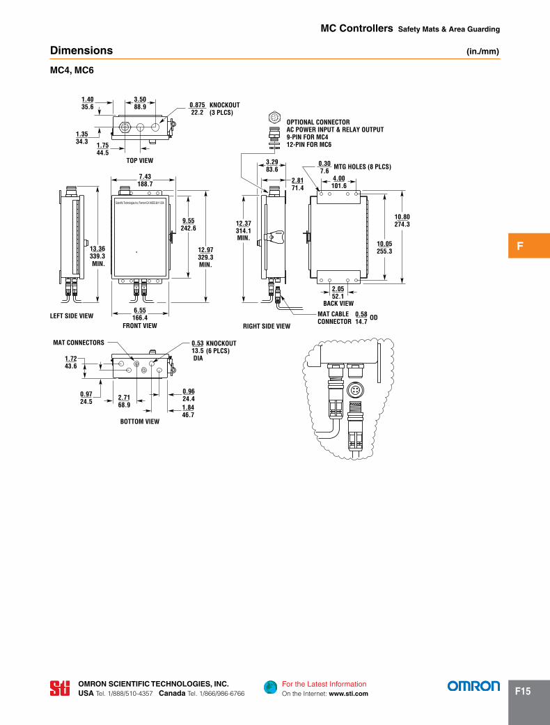
Dimensions (in./mm)
mc4, mc6
Scientific Technologies Inc, Fremont CA 94555-3611 USA
OPTIONAL CONNECTORAC POWER INPUT & RELAY OUTPUT9-PIN FOR MC412-PIN FOR MC6
MIN.
MTG HOLES (8 PLCS)
KNOCKOUT(3 PLCS)
BACK VIEW
ODMAT CABLECONNECTOR
TOP VIEW
MIN.
MAT CONNECTORS
FRONT VIEWLEFT SIDE VIEW
BOTTOM VIEW
MIN.
RIGHT SIDE VIEW
KNOCKOUT(6 PLCS)
0.9624.41.8446.7
0.5313.5
2.7168.9
0.9724.5
1.7243.6
6.55166.4
12.97329.3
13.36339.3
7.43188.7
1.7544.5
1.3534.3
1.4035.6
3.5088.9 0.875
22.2
3.2983.6
2.8171.4
0.307.6
4.00101.6
12.37314.1
9.55242.6
2.0552.1
0.5814.7
10.05255.3
10.80274.3
DIA
mc controllers Safety mats & Area guarding

For the Latest InformationOn the Internet: www.sti.com
OmrOn Scientific technOlOgieS, inc.USA Tel. 1/888/510-4357 canada Tel. 1/866/986-6766f16
f
mc3
Side View
Bottom View
15.30.6
983.9
35.51.4
1104.3
381.5
61.22.4
552.2
7.50.3
1.50.06
752.95
UmDB-6
50.82.00
38.11.50
60.52.38
38.11.50
101.64.00
38.11.50
215.98.50
Mtg Holes
228.69.00
217.48.56
38.11.50 115.8
4.56
78..23.08Ref
75.72.98Ref
Mtg Holes
OUT
MAT1
MAT2
MAT3
MAT6
MAT5
MAT4Mat 3 Mat 4
Mat 2 Mat 5
Mat 1
Out toController
Mat 6
UmDB-10UmDB-8
Mat 6
Mat 8Mat 3
Out to Controller
Mat 7
Mat 1 Mat 10
Mat 2 Mat 9
Mat 4
Mat 5
60.52.38
215.98.50Mtg
Holes
Mtg Holes
OUT
31.81.25
101.64.00
31.81.25
31.81.25
31.81.25
228.69.00
217.48.56
38.11.50
50.82.00
38.11.50
115.84.56
78..23.08Ref
75.72.98Ref
MAT5 MAT6
MAT4 MAT7
MAT3 MAT8
MAT2 MAT9
MAT1 MAT10
Mat 5
Mat 7Mat 2
Out to Controller
Mat 6
Mat 1 Mat 8
Mat 3
Mat 4
60.52.38
215.98.50Mtg
Holes
Mtg Holes
OUT
38.11.50
101.64.00
38.11.50
19.10.75
19.10.75
228.69.00
217.48.56
38.11.50
50.82.00
38.11.50
115.84.56
78..23.08Ref
75.72.98Ref
MAT4 MAT5
MAT3 MAT6
MAT2 MAT7
MAT1 MAT8
Dimensions (continued) (mm/in. )
mc controllers Safety mats & Area guarding

For the Latest InformationOn the Internet: www.sti.com
OmrOn Scientific technOlOgieS, inc.USA Tel. 1/888/510-4357 canada Tel. 1/866/986-6766 f17
f
Wiring
MULTIPLE MATS MAY BE CONNECTED TO THE CONTROLLER USING THIS METHOD.THE ABOVE EXAMPLE SHOWS 4 MATS WIRED.MATS MUST BE CONNECTED IN SEQUENCE, USING ZONE 1, ZONE 2, ZONE 3, etc.DIP SWITCHES MUST BE SET TO THE NUMBER OF ZONES BEING USED.
MAT 4
BLACK
BLUE
WHITE
BROWN
(WHITE)
(BLUE)
(BROWN)(WHITE)(BROWN)(WHITE)(BROWN)
(BLACK)(BLUE)(BLACK)(BLUE)(BLACK)
(WHITE)
(BLUE)
6BRN
6WHT
6BLU
6BLK
5BRN
5BLU
5BLK
4BRN
5WHT
ZONE 5
4WHT
4BLU
4BLK
3BRN
3WHT
3BLU
ZONE 4
1BRN
1WHT
1BLU
1BLK
ZONE 1
TERMINAL CONNECTIONS FOR SAFETY MATS
ZONE 3 ZONE 6
3BLK
2WHT
2BRN
2BLK
2BLU
ZONE 2
MAT 3MAT 2MAT 1
MC6
TB1 TB4
mc6 with multiple mats connected to One Zone
mat connections for listed controllers
• The MC4 and MC6 controllers may be ordered with up to 6 mat connectors (part #60477) installed.
• When using the MC3 controller, part #60477 may be ordered for mounting in customer enclosure.
CONTROLLER WIRE COLORS
MALE CONNECTORMC12 Male Single Key
#20 PIN CONTACT(4 PLCS)
MATING/FACE VIEWMAT CONNECTOR WIRING
INDEX/KEYWAY
1 4
2 3
(MC4)
BRN
BLK
BLU
WHT
(MC6)
BRN
BLK
BLU
WHT
(MC3)
(BROWN)
(BROWN)
(BLACK)(BLACK)BLACK
MAT 1
(BOTTOM)
(TOP PLATE)
BROWN
WHITE BLUE
(BLUE) (BLUE)
(BLUE)
(WHITE) (WHITE)
(WHITE)
M12
M11
M21
M22
mc controllers Safety mats & Area guarding

For the Latest InformationOn the Internet: www.sti.com
OmrOn Scientific technOlOgieS, inc.USA Tel. 1/888/510-4357 canada Tel. 1/866/986-6766f18
f6W
HT6B
RN5W
HT5B
RN4W
HT
3WHT
3BRN
2WHT
4BRN
2BRN
1WHT
1BRN
6BLU
6BLK
5BLU
2BLU
2BLK
1BLU
1BLK
5BLK
4BLK
4BLU
3BLK
3BLU
F3T2A250V
MC4
RELAY OUTPUTS
SHIE
LDST
ART
2ST
ART
1+
24 V
DC IN
24 V
RET
K2JMP2
K1
TERMINAL CONNECTIONS FOR SAFETY MATS
CLEARPOWER SUPPLY
RUN
STOP
RESET
LED1
LED2
LED3
TERMINAL CONNECTIONS FOR SAFETY MATS
JMP3
JMP1
AC IN
NEUT
TB3
TB2
NO 1
NO 1AC IN NEUT
NO 2 NC 1 NC 2
NO 1
NO 2
NO 2
NC 1
NC 1
NC 2
NC 2
CONN
ECT
GREE
N LE
AD T
O GR
OUND
LUG
GREE
N
BLK
WHT
RED
WHT
/BLK
ORN
BLU
RED/
BLK
GRN/
BLK
HOOK-UP IN THIS MANNERWHENEVER OPTIONAL POWERCONNECTOR ASSY IS INSTALLED
FOR ALL 43815-1X1X
mc4 Ac Power, 9-Pin connector
mc4 Dc Power, 9-Pin connector
6WHT
6BRN
5WHT
5BRN
4WHT
3WHT
3BRN
2WHT
4BRN
2BRN
1WHT
1BRN
6BLU
6BLK
5BLU
2BLU
2BLK
1BLU
1BLK
5BLK
4BLK
4BLU
3BLK
3BLU
MC4
RELAY OUTPUTS
TB1
+ 24
VDC
24 V
RET
BLK
WHT
K2JMP2
K1
TERMINAL CONNECTIONS FOR SAFETY MATS
CLEAR
RUN
STOP
RESET
LED1
LED2
LED3
TERMINAL CONNECTIONS FOR SAFETY MATS
JMP3
JMP1
TB2
NO 1
NO 1 NO 2 NC 1 NC 2
NO 1
NO 2
NO 2
NC 1
NC 1
NC 2
NC 2
CONN
ECT
GREE
N LE
AD T
O GR
OUND
LUG
GREE
N
RED
WHT
/BLK
ORN
BLU
RED/
BLK
GRN/
BLK
HOOK-UP IN THIS MANNERWHENEVER OPTIONAL POWERCONNECTOR ASSY IS INSTALLED
FOR ALL 43815-1X1X
7
6
9
5
1
2
8
43MATING VIEW
BLUE
WHT/BLK
GRN/BLKN.C. 1
N.O. 2
N.O. 1
PIN 2
PIN 4
PIN 8
WHITE
NEUT
24 VDC RET
WHITEPIN 5
PIN 5
N.C. 1
N.O. 2
N.O. 1
PIN 1ORANGE
PIN 6
PIN 7GREEN
RED
RED/BLKPIN 3
+24 VDC
AC IN
PIN 9BLACK
BLACKPIN 9
24 VDC
120 VAC POWER CONNECTIONS FOR MC4
24 VDC POWER CONNECTIONS FOR MC4
120 VAC
CONTROL CONNECTIONS FOR MC4
mc controllers Safety mats & Area guarding
Wiring (continued)

For the Latest InformationOn the Internet: www.sti.com
OmrOn Scientific technOlOgieS, inc.USA Tel. 1/888/510-4357 canada Tel. 1/866/986-6766 f19
f
Wiring (continued)
mc6 Ac Power, 12-Pin connector
mc6 Dc Power, 12-Pin connector
12345
GRN/
BLK
TR
BLAC
K
WHI
TE
BLK/
WHT
TR
WHT
/BLK
TR
RED
RED/
BLK
TR
BLU/
BLK
TR
BLUE
ORN/
BLK
TR
ORAN
GE5321 4
NOCK2
AUX OUTPUTS
SAFETYOUTPUTS
NC
NEUT
AC IN
K1
F1T2A250V
UNIVERSALPOWER SUPPLY
FOR AC POWER
+ 24
VDC
MPC
EST
ART
2ST
ART
1
0 VD
C
RELAY OUTPUT BOARD
12345
GRN/
BLK
TRBL
K/W
HT T
R
WHT
/BLK
TR
BLAC
KW
HITE
RED
RED/
BLK
TR
BLU/
BLK
TR
BLUE
ORN/
BLK
TR
ORAN
GE
5321 4
NOCK2
AUX OUTPUTSNCK1
+ 24
VDC
MPC
EST
ART
2ST
ART
1
0 VD
C
RELAY OUTPUT BOARD
F1T2A250V
SAFETYOUTPUTS
TB1
TB1
TB3
J2
TB3
TB2
TB1
TB1
TB3
TB3
J2
TB3
TB2
PIN 6
PIN 7OR/BLK
BLU/BLK
PIN 5RED
GRN/BLK
COM1
NO2
START 2
AUX NO PIN 10
WHITE0 VDC
WHITENEUT PIN 11
PIN 11
NO1
NO2BLUE
ORANGE
WH/BLK
BLK/WHT
RED/BLKMPCE
START 1
AUX COM
PIN 1
PIN 2
PIN 8
PIN 4
PIN 3
GREEN
BLACK+ 24 VDC
BLACKAC IN
PIN 9
PIN 12
PIN 12
100 - 240 VAC POWER CONNECTIONS FOR MC6
24 VDC POWER CONNECTIONS FOR MC6
CONTROL CONNECTIONS FOR MC6
7
8
12
6
5
91
10
3
2
11
4
MATING VIEW
L N
2
1
4
C
5
3
2
5
NO
4
1
TB1
TB1
TB3
J2
TB3
TB2
TB1
TB1
TB3
TB3
J2
TB3
TB2
PIN 6
PIN 7OR/BLK
BLU/BLK
PIN 5RED
GRN/BLK
COM1
NO2
START 2
AUX NO PIN 10
WHITE0 VDC
WHITENEUT PIN 11
PIN 11
NO1
NO2BLUE
ORANGE
WH/BLK
BLK/WHT
RED/BLKMPCE
START 1
AUX COM
PIN 1
PIN 2
PIN 8
PIN 4
PIN 3
GREEN
BLACK+ 24 VDC
BLACKAC IN
PIN 9
PIN 12
PIN 12
100 - 240 VAC POWER CONNECTIONS FOR MC6
24 VDC POWER CONNECTIONS FOR MC6
CONTROL CONNECTIONS FOR MC6
7
8
12
6
5
91
10
3
2
11
4
MATING VIEW
L N
2
1
4
C
5
3
2
5
NO
4
1
mc controllers Safety mats & Area guarding

For the Latest InformationOn the Internet: www.sti.com
OmrOn Scientific technOlOgieS, inc.USA Tel. 1/888/510-4357 canada Tel. 1/866/986-6766f20
f
UmDB-6
OUT
MAT1
MAT2
MAT3
MAT6
MAT5
male
female
male
female
female
female male
Female Terminal InstallsInside Male Terminal
female
male
male
WHT
BLU
BRN
BLK
male
female
female
female male
male
BLK
BRN
BLU
WHT
BLU
WHT BL
K
BRN
BLU
WHT
BRN
BLK
BLK
BRN
BLU
WHT
BLU
WHT BL
K
BRN
BLK
BRN
BLU
WHT
BLK
BRN BL
U
WHT
female
male
female
male
MAT4
UmDB-10
OUT
MAT1
MAT2
MAT4
MAT5
MAT10
MAT9
MAT3 MAT8
MAT7
male
female
male
female
male
female
male
female
female
female male
Female Terminal InstallsInside Male Terminal
female
male
male
WHT
BLU
BRN
BLK
male
female
female
female male
male
female
male
female
male
BLK
BRN
BLU
WHT
BLK
BRN
BLU
WHT
BLK
BRN
BLU
WHT
BLU
WHT BL
K
BRN
BLU
WHT BL
K
BRN
BLU
WHT
BRN
BLK
BLU
WHT
BRN
BLK
BLU
WHT BL
K
BRN
BLK
BRN BLU
WHT
BLK
BRN
BLU
WHT
BLK
BRN BL
U
WHT
female
male
female
male
MAT6
UmDB-8
OUT
MAT1
MAT2
MAT3
MAT4
MAT8
MAT7
MAT6
male
female
male
female
male
female
female
female male
Female Terminal InstallsInside Male Terminal
female
male
male
WHT
BLU
BRN
BLK
male
female
female
female male
male
female
male
BLK
BRN
BLU
WHT
BLK
BRN
BLU
WHT
BLU
WHT BL
K
BRN
BLU
WHT BL
K
BRN
BLU
WHT
BRN BL
K
BLU
WHT BL
K
BRN
BLK
BRN
BLU
WHT
BLK
BRN
BLU
WHT
BLK
BRN BL
U
WHT
female
male
female
male
MAT5
mc controllers Safety mats & Area guarding
Wiring (continued)

For the Latest InformationOn the Internet: www.sti.com
OmrOn Scientific technOlOgieS, inc.USA Tel. 1/888/510-4357 canada Tel. 1/866/986-6766 f21
f
Suggested machine and Plc connections
mc3, two normally Open Safety relay Outputs
13 14 23 24 31 32 41 42
STOP
X1 X2 M11M12M21M22
MACHINE MOTOR VOLTAGE
CUSTOMER SUPPLIED FUSE
5 AMPS OR LESS
NC
NCT0 PLC FOR MONITORING
FUSE
M
RUN
START
MAT CLEAR
24VDCPOWER TO CONTROLLER
M12
OPTIONALKEY SWITCH
ORPUSH BUTTON
RESET
(BRN)
(BLK)
(WHT)
MAT 1 MAT 2 MAT 3
(BLU)
(BRN)
(BLK)
(WHT)
(BLU)
(WHT)
(BLU)
(BRN)
(BLK)
(BLU)
(WHT)
M11
M21
M22
Y2-
Y1+
OUTPUTS250 VAC 6 A 1500 VA MAX
BLK BRN BLUMAT
WHT24VDC
2.2VA
mc controllers Safety mats & Area guarding

For the Latest InformationOn the Internet: www.sti.com
OmrOn Scientific technOlOgieS, inc.USA Tel. 1/888/510-4357 canada Tel. 1/866/986-6766f22
f
mc4, two normally Open Safety relay Outputs, 100 to 240 VAc Power
OPTIONALKEY SWITCH
ORPUSH BUTTON
RESET
100 TO 240 VACPOWER TO CONTROLLER
CONNECTS TOTERMINALINSIDEENCLOSURE
6WHT
6BRN
5WHT
5BRN
4WHT
3WHT
3BRN
2WHT
4BRN
2BRN
1WHT
1BRN
6BLU
6BLK
5BLU
2BLU
2BLK
1BLU
1BLK
5BLK
4BLK
4BLU
3BLK
3BLU
F3T2A
250V
MC4
M
NC1NC1
NC 2NC 1NO 2
RELAY OUTPUTS
SHIE
LD
AC IN
STAR
T 2
STAR
T 1
+ 24
VDC
IN24
V R
ET
K2JMP2
JUMPER JUMPER
K1
NO 1
TO PLCCONTROL
CUSTOMER SUPPLIED FUSE
7 AMPS OR LESS
FUSE
MACHINE MOTOR VOLTAGE
TERMINAL CONNECTIONS FOR SAFETY MATS
CLEAR
UNIVERSALPOWER SUPPLY
(OPTIONAL)FOR AC POWER
RUN
STOP
RESET
LED1
LED2
LED3
TERMINAL CONNECTIONS FOR SAFETY MATS
JMP3
JMP1
BLACKBLUE
BROWN
WHITE
MAT 1
BLACKBLUE
BROWN
WHITEMAT 2
NEUT
UP TO 6 MATS MAY BE CONNECTED TO THECONTROLLER USING THIS METHOD.AS EACH MAT IS CONNECTED, THE JUMPER ISMOVED TO THE LAST UNUSED TERMINAL.THE ABOVE EXAMPLE SHOWS TWO MATS WIRED,JUMPERS WOULD BE PLACED AS SHOWN.(3 BLK) IS JUMPERED TO TERMINAL LABELED 6 BLU &(3 BRN) IS JUMPERED TO TERMINAL LABELED 6 WHT.WHEN ALL 6 MATS ARE CONNECTED, JUMPERS ARE NOT REQUIRED.
mc controllers Safety mats & Area guarding
Suggestioned machine and Plc connections (continued)
For the Latest InformationOn the Internet: www.sti.com
OmrOn Scientific technOlOgieS, inc.USA Tel. 1/888/510-4357 canada Tel. 1/866/986-6766 f23
f
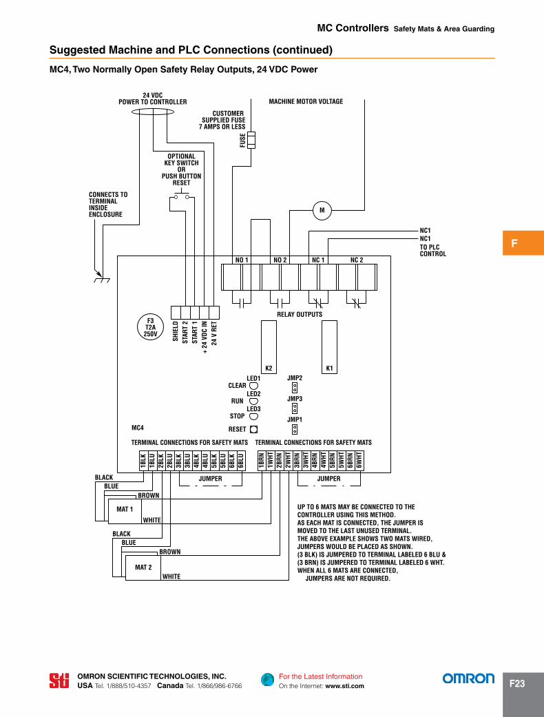
Suggested machine and Plc connections (continued)
mc4, two normally Open Safety relay Outputs, 24 VDc Power
UP TO 6 MATS MAY BE CONNECTED TO THECONTROLLER USING THIS METHOD.AS EACH MAT IS CONNECTED, THE JUMPER ISMOVED TO THE LAST UNUSED TERMINAL.THE ABOVE EXAMPLE SHOWS TWO MATS WIRED,JUMPERS WOULD BE PLACED AS SHOWN.(3 BLK) IS JUMPERED TO TERMINAL LABELED 6 BLU &(3 BRN) IS JUMPERED TO TERMINAL LABELED 6 WHT.WHEN ALL 6 MATS ARE CONNECTED, JUMPERS ARE NOT REQUIRED.
OPTIONALKEY SWITCH
ORPUSH BUTTON
RESET
24 VDCPOWER TO CONTROLLER
CONNECTS TOTERMINALINSIDEENCLOSURE
6WHT
6BRN
5WHT
5BRN
4WHT
3WHT
3BRN
2WHT
4BRN
2BRN
1WHT
1BRN
6BLU
6BLK
5BLU
2BLU
2BLK
1BLU
1BLK
5BLK
4BLK
4BLU
3BLK
3BLU
F3T2A250V
MC4
M
NC1NC1
NC 2NC 1NO 2
RELAY OUTPUTS
SHIE
LDST
ART
2ST
ART
1+
24 V
DC IN
24 V
RET
K2JMP2
JUMPER JUMPER
K1
NO 1
TO PLCCONTROL
CUSTOMER SUPPLIED FUSE
7 AMPS OR LESS
FUSE
MACHINE MOTOR VOLTAGE
TERMINAL CONNECTIONS FOR SAFETY MATS
CLEAR
RUN
STOP
RESET
LED1
LED2
LED3
TERMINAL CONNECTIONS FOR SAFETY MATS
JMP3
JMP1
BLACKBLUE
BROWN
WHITE
MAT 1
BLACKBLUE
BROWN
WHITEMAT 2
mc controllers Safety mats & Area guarding

For the Latest InformationOn the Internet: www.sti.com
OmrOn Scientific technOlOgieS, inc.USA Tel. 1/888/510-4357 canada Tel. 1/866/986-6766f24
f
mc6, two normally Open Safety relay Outputs, 100 to 240 VAc Power
OPTIONALKEY SWITCH
ORPUSH BUTTON
CONNECTSINSIDEENCLOSURE
UP TO 6 MATS MAY BE CONNECTED TO THE CONTROLLER USING THIS METHOD.THE ABOVE EXAMPLE SHOWS TWO - 4 WIRE SAFETY MATS CONNECTED.MATS MUST BE CONNECTED IN SEQUENCE, USING ZONE 1, ZONE 2, ZONE 3, ETC.DIP SWITCHES MUST BE SET TO THE NUMBER OF ZONES BEING USED. IN MOST CASES SHIELDING IS NOT REQUIRED FOR “MPCE” AND REMOTE START WIRING.
SNUBBER
12345
NONCC
54321
NO
NC
CTO PLC
CONTROL
100 TO 240 VACPOWER TO CONTROLLER
(+) MACHINE CONTROL VOLTAGE
K2
SAFETY OUTPUTS
AUX OUTPUTS
K1
SAFETY RELAY OUTPUT BOARD(OPTIONAL)FOR AC POWER
UNIVERSALPOWER SUPPLY
6BRN
6WHT
6BLU
6BLK
5BRN
5BLU
5BLK
4BRN
5WHT
ZONE 5
4WHT
4BLU
4BLK
3BRN
3WHT
3BLU
ZONE 4
1BRN
1WHT
1BLU
1BLK
ZONE 1
TERMINAL CONNECTIONS FOR SAFETY MATS
ZONE 3 ZONE 6
76
45
ON ON
67
45
SW2
321
3BLK
2WHT
2BRN
23
1
2BLK
2BLU
SW1
ZONE 2
MPC
E
+ 24
VDC
STAR
T 2
STAR
T 1
0 VD
CNEUT
AC IN
WHT
BRN
BLUE
MAT 1
BLACK
BLACK
BLUEBOTTOMPLATE
WHITE
BROWN
MC6
GND
RESET
MPCE1
MPCE2
MPCE1
MPCE2
TOPPLATE
MAT 2
TOMACHINECONTROL
FACTORYINSTALLED JUMPER
REMOVE WHENMPCE IS USED
F1T2A250V
SNUBBER
CR
CR
CUSTOMER SUPPLIEDFUSE
7 AMPS OR LESSMPCE1
MPCE2
TB3
TB2
TB1 TB4
TB1
J2
FUSE
FUSE
N(-)
ON
mc controllers Safety mats & Area guarding
Suggestioned machine and Plc connections (continued)

For the Latest InformationOn the Internet: www.sti.com
OmrOn Scientific technOlOgieS, inc.USA Tel. 1/888/510-4357 canada Tel. 1/866/986-6766 f25
f
OPTIONALKEY SWITCH
ORPUSH BUTTON
CONNECTSINSIDE
ENCLOSURE
IN MOST CASES UP TO 6 MATS MAY BE CONNECTED TO THE CONTROLLER USING THIS METHOD.THE ABOVE EXAMPLE SHOWS TWO - 4 WIRE SAFETY MATS CONNECTED.MATS MUST BE CONNECTED IN SEQUENCE, USING ZONE 1, ZONE 2, ZONE 3, ETC.DIP SWITCHES MUST BE SET TO THE NUMBER OF ZONES BEING USED. IN MOST CASES SHIELDING IS NOT REQUIRED FOR “MPCE” AND REMOTE START WIRING.
12345
SOLID STATE OUTPUT BOARD
6BRN
6WHT
6BLU
6BLK
5BRN
5BLU
5BLK
4BRN
5WHT
ZONE 5
4WHT
4BLU
4BLK
3BRN
3WHT
3BLU
ZONE 4
1BRN
1WHT
1BLU
1BLK
ZONE 1
TERMINAL CONNECTIONS FOR SAFETY MATS
ZONE 3 ZONE 6
76
45
ON ON
67
45
SW2
321
3BLK
2WHT
2BRN
23
1
2BLK
2BLU
SW1
ZONE 2
MPC
E
+ 24
VDC
STAR
T 2
STAR
T 1
0 VD
C
WHT
BRN
BLUE
MAT 1
BLACK
BLACK
BLUEBOTTOMPLATE
WHITE
BROWN
MC6
RESET
MPCE1
MPCE2
TOPPLATE
MAT 2
TOMACHINECONTROL
FACTORYINSTALLED JUMPER
REMOVE WHENMPCE IS USED
TVSMPCE2
CR
1 2 3 4 5 6
AUX
NPN
AUX
PNP
0 VD
C
OSSD
B
OSSD
A
0 VD
C
MPCE1
MPCE2
24 VDCPOWER TO CONTROLLER
AUX INPUTS TO PLC
TVSMPCE1
CR
TRANSIENT VOLTAGE SUPPRESSORSARE OPTIONAL
TB1 TB4
TB3
J2
ON
mc6, two Solid-State Safety Outputs, 24 VDc Power
Suggested machine and Plc connections (continued)
mc controllers Safety mats & Area guarding

For the Latest InformationOn the Internet: www.sti.com
OmrOn Scientific technOlOgieS, inc.USA Tel. 1/888/510-4357 canada Tel. 1/866/986-6766f26
f
mc-3 mc3
mc3 Series Safety mat controllerNo options are available
mc-4 mc4 –
Power input connector0 No power input & safety output connector1 Power input & safety output connectorlid mounted Key-switch0 No key-switch1 Factory installed lid mounted key-switchPower input Voltage0 24 VDC1 100-240 VAC auto-selectingmat input connectors0 No mat connectors__ Please specify a number between 1 & 6
mc-6 mc6 –
input VoltageAc AC powerDc DC powerPower input connector0 No power input & safety output connector1 Power input & safety output connectorlid mounted reset Keyswitch0 No reset keyswitch1 Factory installed lid mounted reset keyswitchSafety Output module1 Safety relay2 Solid-state (not available with AC input)mat input connectors0 No mat connectors__ Please specify a number between 1 & 6
Safety Standards and PrecautionsA Safety Mat controller is a general purpose, safety mat control
device and is not designed for any specific type, model or brand of machine. All safety-related functions of the guarded machine controls including pneumatic, electric, logic or hydraulic controls must be control reliable.
A Safety Mat controller when combined with a four-wire safety mat meets ANSI/RIA R15.06-1999, ANSI B11.19-2003 and the following applicable OSHA standards. When used with mechani-cal power presses, OSHA standard 1910.217(c) applies. For other applications the requirements of section 1910.212 apply.
Only use a Safety Mat controller and four-wire safety mat system on machinery that stops consistently and immediately any-where in its cycle or stroke. Never use a Safety Mat controller and four-wire safety mat system on a full-revolution clutched press or machine. Access to the point of operation or hazardous machine area not protected by the Safety Mat controller and four-wire safety mat system must be guarded by fencing, barriers or other appropriate methods.
The purchaser, installer and employer are responsible for meeting all local state and federal government laws, rules, codes or regulations relating to the proper use, installation, operation and maintenance of this control and the guarded machine. See Installation and Operation Manual for details.
All application examples described are for illustration purposes only. Actual installations may differ from those indicated.
For information on Omron STI safety mats, see page F2✎
mc controllers Safety mats & Area guarding
Ordering
rapid Delivery ProductsThe following models are readily available for shipment today or at least within 3 days. Please consider these for all new applications.
model Part number Description
mc3 controller
MC3 43767-0010 Din - 24 VDC
mc4 controllers
MC4-0004 43815-0004 NEMA 24, VDC, 4 mat connectors
MC4-0010 43815-0010 NEMA 24 VDC or 100-240 VAC, No connector
MC4-0011 43815-0011 NEMA 24 VDC or 100-240 VAC, 1 mat connector
MC4-0012 43815-0012 NEMA 24 VDC or 100-240 VAC, 2 mat connectors
MC4-0013 43815-0013 NEMA 24 VDC or 100-240, VAC, 3 mat connectors
MC4-0014 43815-0014 NEMA 24 VDC or 100-240, VAC, 4 mat connectors
mc6 controllers
MC6AC-0016 43938-0016 NEMA 24 VDC or 100-240 VAC, 6 mat connectors
MC6DC-0012 43939-0012 NEMA 24 VDC, 2 mat connectors
MC6DC-0016 43939-0016 NEMA 24 VDC, 6 mat connectors
= Highlighted rapid Delivery products are available for shipment today or within three days.