Embed Size (px)
Citation preview

Safety ManagerPlanning and Design Guide
EP-SM.MAN.6276Issue 1.0
October 2014
Release 152

ii
Notice
This document contains Honeywell proprietary information. Information contained herein is to be used solely for the purpose submitted, and no part of this document or its contents shall be reproduced, published, or disclosed to a third party without the express permission of Honeywell Safety Management Systems.
While this information is presented in good faith and believed to be accurate, Honeywell disclaims the implied warranties of merchantability and fitness for a purpose and makes no express warranties except as may be stated in its written agreement with and for its customer.
In no event is Honeywell liable to anyone for any direct, special, or consequential damages. The information and specifications in this document are subject to change without notice.
Specific products described in this document are covered by U.S. Patent Nos. D514075, D518003, D508469, D516047, D519470, D518450, D518452, D519087 and any foreign patent equivalents.
Copyright 2014 – Honeywell Safety Management Systems, a division of Honeywell Aerospace B.V.
Honeywell trademarks
Experion PKS®, PlantScape®, SafeBrowse®, TotalPlant® and TDC 3000® are U.S. registered trademarks of Honeywell International Inc.
Other trademarks
Microsoft and SQL Server are either registered trademarks or trademarks of Microsoft Corporation in the United States and/or other countries.
Trademarks that appear in this document are used only to the benefit of the trademark owner, with no intention of trademark infringement.
Document Release Issue Date
EP-SM.MAN.6276 152 1.0 October 2014

iii
Support and other contacts
United States and Canada
Europe
Pacific
Contact: Honeywell Solution Support Center
Phone: 1-800 822-7673. In Arizona: (602) 313-5558 Calls are answered by dispatcher between 6:00 am and 4:00 pm Mountain Standard Time. Emergency calls outside normal working hours are received by an answering service and returned within one hour.
Facsimile: (602) 313-3293
Mail: Honeywell IS TAC, MS P13 2500 West Union Hills Drive Phoenix, AZ, 85027
Contact: Honeywell PACE TAC
Phone: +32-2-728-2657
Facsimile: +32-2-728-2278
Mail: Honeywell TAC BE02 Hermes Plaza Hermeslaan, 1H B-1831 Diegem, Belgium
Contact: Honeywell Global TAC - Pacific
Phone: 1300-36-4822 (toll free within Australia)+61-2-9362-9559 (outside Australia)
Facsimile: +61-2-9362-9564
Mail: Honeywell Limited Australia 5 Kitchener Way Burswood 6100, Western Australia
Email [email protected]

iv
India
Korea
People’s Republic of China
Contact: Honeywell Global TAC - India
Phone: +91 20 6603 2718 / 19 and 1800 233 5051
Facsimile: +91-20-66039800
Mail: Honeywell Automation India Ltd. 56 and 57, Hadapsar Industrial Estate Hadapsar, Pune –411 013, India
Email [email protected]
Contact: Honeywell Global TAC - Korea
Phone: +82-2-799-6317 +82-11-9227-6324
Facsimile: +82-2-792-9015
Mail: Honeywell Co., Ltd 17F, Kikje Center B/D, 191, Hangangro-2Ga Yongsan-gu, Seoul, 140-702, Korea
Email [email protected]
Contact: Honeywell Global TAC - China
Phone: +86- 21-52574568
Mail: Honeywell (China) Co., Ltd 33/F, Tower A, City Center, 100 Zunyi Rd. Shanghai 200051, People’s Republic of China
Email [email protected]

v
Singapore
Taiwan
Japan
Elsewhere
Call your nearest Honeywell office.
World Wide Web
Honeywell Solution Support Online:
http://www.honeywell.com/ps.
Contact: Honeywell Global TAC - South East Asia
Phone: +65-6580-3500
Facsimile: +65-6580-3501 +65-6445-3033
Mail: Honeywell Private Limited Honeywell Building 17, Changi Business Park Central 1 Singapore 486073
Email [email protected]
Contact: Honeywell Global TAC - Taiwan
Phone: +886-7-536 2567
Facsimile: +886-7-536 2039
Mail: Honeywell Taiwan Ltd. 17F-1, No. 260, Jhongshan 2nd Road. Cianjhen District Kaohsiung, Taiwan, ROC
Email [email protected]
Contact: Honeywell Global TAC - Japan
Phone: +81-3-6730-7276
Facsimile: +81-3-6730-7228
Mail: Honeywell Japan K.K New Pier Takeshiba, South Tower Building, 20th Floor, 1-16-1 Kaigan, Minato-ku, Tokyo 105-0022, Japan
Email [email protected]

vi
Training classes
Honeywell holds technical training classes on Safety Manager. These classes are taught by experts in the field of process control systems. For more information about these classes, contact your Honeywell representative, or see http://www.automationcollege.com.
Related Documentation
The following guides are available for Safety Manager.
The guide in front of you is Planning and Design Guide.
Guide Description
The Overview Guide This guide describes the general knowledge required, the basic functions of, and the tasks related to Safety Manager.
The Safety Manual This guide describes the specifications, design guidelines, and safety aspects related to Safety Manager.
The Planning and Design Guide
This guide describes the tasks related to planning and designing a Safety Manager project.
The Installation and Upgrade Guide
This guide describes the tasks related to installing, replacing and upgrading hardware and software as part of a Safety Manager project.
The Troubleshooting and Maintenance Guide
This guide describes the tasks related to troubleshooting and maintaining Safety Manager.
The System Administration Guide
This guide describes the task related to administrating the computer systems used in a Safety Manager project.
The Hardware Reference This guide specifies the hardware components that build a Safety Manager project.
The Withdrawn Hardware Reference
This guide specifies all withdrawn hardware components and identifies alternatives for maintaining Safety Manager projects containing withdrawn hardware.
The Software Reference This guide specifies the software functions that build a Safety Manager project and contains guidelines on how to operate them.
The On-line Modification Guide
This guide describes the theory, steps and tasks related to upgrading Safety Builder and embedded software and modifying an application online in a redundant Safety Manager.

vii
Task-oriented guides
A task-oriented guide provides both procedural and basic knowledge. A task can inform the reader on how to perform the task in terms of steps to follow. Additionally a task can describe what important considerations to make or what options to choose from when performing a task.
A task-oriented guide lists the required skills and knowledge that people must master to qualify for the described tasks.
It is common for task oriented guides to refer to reference guides for details.
Reference guides
A reference guide provides detailed information or solutions regarding its scope. A reference guide is a Safety Manager related guide and provides background information to support tasks as described in task-oriented guides.
A reference guide does not describe tasks in terms of how to perform the task in terms of steps to follow.
Available electronic format
All guides are available as Adobe PDF guides that can be viewed with Acrobat Reader or a compatible reader. These PDF guides are provided on the Safety Manager CD-ROM, in a separate PDF Collection folder.
Conventions
Symbols
The following symbols are used in Safety Manager documentation:
Attention
This symbol is used for information that emphasizes or supplements important points of the main text.
Tip
This symbol is used for useful, but not essential, suggestions.
Note
This symbol is used to emphasize or supplement important points of the main text.

viii
Caution
This symbol warns of potential damage, such as corruption of the database.
Warning
This symbol warns of potentially hazardous situations, which, if not avoided, could result in serious injury or death.
ESD
This symbol warns for danger of an electro-static discharge to which equipment may be sensitive.

ix
Fonts
The following fonts are used in Safety Manager documentation:
Emphasis• “... inform the reader on how to perform
the task in terms of...”• “...see the Overview Guide”
Emphasised text is used to:• emphasise important words in the text,• identify document titles.
Label
“The Advanced tab of the Properties dialog has..”
This font is used to identify labels and titles of (popup) dialogs. Labels are used for Dialog box labels, menu items, names of properties, and so on.
Steps
Take the following steps:1. Create a plant and set its properties.
2. ....
This font is used to identify steps. Steps indicate the course of action that must be adhered to, to achieve a certain goal.
User Variable
..create the My Projects folder and store the readme.txt file here...press the Tab key.. Next press Enter to..
This font is used to:1. identify a user variable, a filename, an
object or view.2. highlight the keys the user should press on
the keyboard.User variable is a variable, an object or a view that the reader can call-up to view or to manipulate.
Value
“Low is the fault reaction state for digital inputs and digital outputs.”
This font is used to indicate a value. Value is a variable that the reader must resolve by choosing a pre-defined state.
Variable
“The syntax is: filename [-s] [-p]“This font is used to identify a variable.Variables are used in syntax and code examples.
http://www.honeywellsms.com This font is used to identify a URL, directing a reader to a website that can be referred to.

x

Safety Manager Planning and Design Guide xi
Contents
1 The Planning and Design Guide1Content of Planning and Design Guide3Prerequisites for Planning and Design Guide5
Generic skills5Technical skills and knowledge5Safety Manager training5
Basic skills and knowledge6Prerequisite skills6Training6
Safety standards for Process & Equipment Under Control (PUC, EUC)7Safety Integrity Level (SIL)7Safety layers of protection8Equipment Under Control (EUC)8Process Under Control (PUC)9
Application design conform IEC 61131-310The IEC 61508 and IEC 61511 standards11
2 Planning a Safety Manager project15Planning the project stages16
Roles and responsibilities16Project planning17Kick-off meeting18Preparing a Bill Of Materials (BOM)19Preparing the QA/QC documentation19Review of customer and sales information20Engineering22Assembly22Testing23Transport24Site installation24
Developing the System Design Specifications (SDS)25Developing the Functional Design Specification (FDS)25Developing the Software Detailed Design Specification (SDDS)
32
3 Safety strategy planning and specification37Safety and availability planning38
General38

Contents
xii Release 152, Issue 1.0
Safety planning38Availability planning 40Safety consultancy41
Overall safety life cycle43The safety integrity level of the process49The field instrumentation50The safety-related system functions51Approval of the specification53
4 Planning the computer- and network infrastructure55Peer-to-peer connections56
Peer-to-peer connections56Long distance connections58Communication functions58
Servers, stations and software61Safety Stations and Experion Stations61Safety Manager related software61Station requirements62Time servers63
Planning system security 64Network security64Safety Builder privileges65
Planning and designing physical networks67Planning considerations68Communication port allocation70Designing the physical network71Time synchronization75Determining communication capacity76
Planning a station network77Supported protocols77
Integration into an Experion FTE network78About compatibility80
5 Planning the system design83System architectures85
General 8 5System configuration85Choosing the architecture based on use88Choosing the architecture based on various requirements88
Checking the systems capacity90Configurable points90Application capacity90Communication capacity91Cycle time95
Choosing settings based on safety and availability96

Contents
Safety Manager Planning and Design Guide xiii
IO settings96System settings98
Safety Manager Controller101Controller chassis101Safety Manager Controller101QPP102COM103PSU105BKM105
Safety Manager IO107IO chassis107IO modules109
Cabling and FTAs114SIC cables114COM cables115IO FTAs116COM FTAs116Location of FTAs116Field cables117
Power concept119Calculating power consumption and heat dissipation119Planning the power supply120PSU architectures124Planning feeders127Planning Earthing concept and ELD use127
Third party equipment129System cabinets130
Planning the cabinet layout130Planning cabinet-related hardware135Planning cabinet packaging and delivery140
6 Planning the application design141Planning the point allocation142
Point allocation considerations142Importing a point database144Duplicate and unallocated Points144
Planning the logical connection configuration145Planning the functional logic design146
FLD design considerations146The Import FLDs function149
Application verification150
7 Planning modifications153Modifications: upgrades and changes154
Offline modifications154

Contents
xiv Release 152, Issue 1.0
Online modifications (OLM)155Planning considerations for modifications155
Competencies of people158Training158Obtaining information on training158
Precautions when working on Safety Managers159EMC warning159Electrostatic discharge (ESD)159Keep the doors closed160Key switches160
Planning hardware modifications161General precautions for hardware modifications161Considerations when planning hardware modifications163Updating documentation163
Planning software modifications164General precautions for software modifications164Considerations when planning software modifications165Updating documentation165
8 Planning decommissioning167
9 Planning training169
List of abbreviations171
Safety Manager Glossary175

Safety Manager Planning and Design Guide xv
Figures
Figure 1 The concept of layers of protection8Figure 2 Example FLD layout10Figure 3 Overall safety life cycle43Figure 4 E/E/PES safety life cycle (in realization phase)44Figure 5 Software safety life cycle (in realization phase)45Figure 6 Relationship of overall safety life cycle to E/E/PES and software
safety life cycles45Figure 7 Example of Functional Logic Diagram (FLD)52Figure 8 Example of various networks in the Network Configurator71Figure 9 Examples of non-redundant communication links between Safety
Managers72Figure 10 Examples redundant communication links between Safety
Managers73Figure 11 Examples of redundant communication links with other systems73Figure 12 Typical example of an RS232 connection based on connected CPs
74Figure 13 Typical example of an RS485 connection based on redundant
communication75Figure 14 Example - connecting an Ethernet switch to the USI-0001 and the
(FTE) LAN78Figure 15 Safety Manager system configuration86Figure 16 Communication memory allocation per channel92Figure 17 Properties of an analog output module97Figure 18 Point details extract, showing the Safety related field location
(center)98Figure 19 Front view of a redundant Controller, placed in a Controller chassis
101Figure 20 Examples of the positioning of redundant and non-redundant IO in
Safety Manager cabinets108Figure 21 Power Supply Units configurations (2 examples for each
configuration)126Figure 22 Example of four cabinets built together131Figure 23 Typical Safety Manager cabinet layout (front view)133Figure 24 Typical Safety Manager cabinet layout (side and top view)134Figure 25 Example of an FLD146Figure 26 ESD Wrist Strap connected to ESD bonding point159

Figures
xvi Release 152, Issue 1.0
Figure 27 Failure model184Figure 28 Example of a multidrop connection based on Ethernet189Figure 29 Programmable electronic system (PES): structure and terminology
193Figure 30 Schematic diagram of a SMOD with 4 channels200

Safety Manager Planning and Design Guide xvii
Tables
Table 1 IEC 61508 versus IEC 61511 terminology12Table 2 Overview of tests in various stages of an Safety Manager project23Table 3 Standard FLD sheet numbering35Table 4 Target failure measures and corresponding SIL level for safety
instrumented functions allocated to Safety Manager operating in low demand mode of operation39
Table 5 Target failure measures and corresponding SIL level for safety instrumented function, allocated to Safety Manager operating in high demand or continuous mode of operation40
Table 6 Safety Manager architectures - levels of availability41Table 7 Overall safety life cycle overview46Table 8 Overview of peer-to-peer connections56Table 9 Safety Manager related software packages61Table 10 Privileges for different users in Safety Builder65Table 11 Network solutions for various Safety Manager actions68Table 12 Overview of network types69Table 13 Communication port and protocol mapping70Table 14 Compatibilty between Safety Manager and other products80Table 15 Safety Manager hardware overview87Table 16 Typical system architectures for typical uses88Table 17 System architectures and the requirements they meet89Table 18 Maximum number of configurable points in a single Safety
Manager90Table 19 Application capacity of a single Safety Manager91Table 20 Considerations for selecting the communication link architecture
104Table 21 Choosing an input module/converter/FTA combination110Table 22 Choosing an output module/converter/FTA combination111Table 23 Pepperl+Fuchs modules for use with hazardous field signals112Table 24 MTL modules for use with hazardous field signals112Table 25 Possible ways to connect input field signals to input modules
(read table from left to right to see possible interface and wiring options)114
Table 26 Possible ways to connect output field signals to output modules (read table from left to right to see possible interface and wiring options)114
Tables
xviii Release 152, Issue 1.0
Table 27 Maximum distances for different communication protocols and speed115
Table 28 Routing of cables carrying different voltages118Table 29 Safety Manager power supply units121Table 30 Cabinet access options of standard Safety Manager
cabinets136Table 31 Safety Manager hardware modifications: online or
not?162Table 32 Safety Manager software modifications: online or
not?164Table 33 Safety integrity levels: target failure measures for a
safety function, allocated to the Safety Instrumented System operating in low demand mode of operation196
Table 34 Safety integrity levels: target failure measures for a safety function, allocated to the Safety Instrumented System operating in high demand or continuous mode of operation196

Safety Manager Planning and Design Guide 1
1The Planning and Design Guide
The Planning and Design Guide is intended primarily for the people responsible for and performing tasks related to Safety Manager.
This guide describes planning and design-related issues and contains enough information for the reader to carry out high-level design and planning tasks to realize a Safety Instrumented System (SIS).
It describes guidelines for the planning of:
• Project stages (page 15)
• Safety strategy (page 37)
• Computer and network infrastructure (page 55)
• Hardware design (page 83)
• Application design (page 141)
• Modifications (repairs, changes and upgrades) (page 153)
• Decommissioning (page 167)
• Training (page 169)
Typical readers of this guide are Project managers and engineers, who need to plan a completely new Safety Manager project, or plan a change or upgrade in an existing Safety Manager configuration. The Planning and Design Guide helps the reader to develop plans and produce cost estimates.
It is assumed that the reader masters the required skills and knowledge as described in this section of the Planning and Design Guide.

1 – The Planning and Design Guide
2 Release 152, Issue 1.0
This section contains the following information:
Topic See
Content of Planning and Design Guide page 3
Prerequisites for Planning and Design Guide page 5
Basic skills and knowledge page 6
Safety standards for Process & Equipment Under Control (PUC, EUC) page 7
Application design conform IEC 61131-3 page 10
The IEC 61508 and IEC 61511 standards page 11
Note
This guide does not contain information related to other Honeywell Experion PKS systems and third-party controllers such as Allen-Bradley, Series 9000, TDC 3000, Data Hiway, UDC, PlantScape, and so on.For information about these systems, see the manufacturers documentation.

Content of Planning and Design Guide
Safety Manager Planning and Design Guide 3
Content of Planning and Design GuidePlanning and Design Guide is a task-oriented guide providing both procedural and basic knowledge. A task can inform the reader on how to perform the task in terms of steps to follow. Additionally a task can describe what considerations to make or options to choose from when performing a task.
The following tasks can be distinguished when planning a Safety Manager project (continued):
• Plan the Safety Manager project stages
• Develop specifications (FDS and PAS)
• Plan safety strategy (safety and availability)
• Plan project details
• Plan changes, upgrades and decommissioning
This section contains the following information about this guide:
Guide subjects
Planning and Design Guide • Planning a Safety Manager project• Safety strategy planning and specification• Planning the computer- and network infrastructure• Planning the system design• Planning the application design• Planning modifications• Planning decommissioning • Planning training

1 – Competences and precautions
4 Release 152, Issue 1.0
References
Guide Description
The Overview Guide This guide describes the general knowledge required, the basic functions of, and the tasks related to Safety Manager.
The Safety Manual This guide describes the specifications, design guidelines, and safety aspects related to Safety Manager.
The Hardware Reference This guide specifies the hardware components that build a Safety Manager project.
The Withdrawn Hardware Reference
This guide specifies all withdrawn hardware components and identifies alternatives for maintaining Safety Manager projects containing withdrawn hardware.
The Software Reference This guide specifies the software functions that build a Safety Manager project and contains guidelines on how to operate them.
The On-line Modification Guide
This guide describes the theory, steps and tasks related to upgrading Safety Builder and embedded software and modifying an application online in a redundant Safety Manager.
The Installation and Upgrade Guide
This guide describes the tasks related to installing, replacing and upgrading hardware and software as part of a Safety Manager project.

Prerequisites for Planning and Design Guide
Safety Manager Planning and Design Guide 5
Prerequisites for Planning and Design GuideEach user shall as a minimum master the skills and knowledge as described in “Basic skills and knowledge” on page 6.
In addition the following task related prerequisites are defined as a minimum for users confronted with tasks as described in Planning and Design Guide.
Generic skillsThe user shall master these skills on an adequate level.
• Project management skills
• Communication skills in English
• Planning and design skills, extended with safety design skills and knowledge.
Technical skills and knowledgeThe user shall master these skills on an adequate level.
• Logistical knowledge (INCOTERMS)
• Computer networking
• Site, process and plant knowledge
• Understanding of Cause & Effect matrices, P&ID or Safety Narratives
• Detailed Safety Manager knowledge
• Be familiar with the Safety Manual
• Knowledge of design and engineering tools related to Safety Manager design.
Safety Manager trainingHoneywell offers a number of trainings related to above mentioned prerequisites. When requesting a training at Honeywell, mention the task you want to perform and make sure that the following goals are met:
• Determination of SIL loops (Safety Consultancy)
• Detailed Safety Manager knowledge
• Skills and knowledge of design and engineering tools related to Safety Manager design

1 – The Planning and Design Guide
6 Release 152, Issue 1.0
Basic skills and knowledgeBefore performing tasks related to Safety Manager you need to:
• Understand basic Safety Manager concepts as explained in the Overview Guide and the Glossary.
• Have a thorough understanding of the Safety Manual.
• Have had appropriate training related to Safety Manager that certifies you for your tasks (see Planning training).
More related information can be found in Prerequisite skills and Training.
Prerequisite skillsWhen you perform tasks related to Safety Manager, it is assumed that you have appropriate knowledge of:
• Site procedures
• The hardware and software you are working with. These may i.e. be: computers, printers, network components, Controller and Station software.
• Microsoft Windows operating systems.
• Programmable logic controllers (PLCs).
• Applicable safety standards for Process & Equipment Under Control.
• Application design conform IEC 61131-3.
• The IEC 61508 and IEC 61511 standards.
This guide assumes that you have a basic familiarity with the process(es) connected to the equipment under control and that you have a complete understanding of the hazard and risk analysis.
More related information can be found in Training.
TrainingMost of the skills mentioned above can be achieved by appropriate training. For more information, contact your Honeywell SMS representative or see:
• http://www.automationcollege.com.
More related information can be found in Prerequisite skills.

Safety standards for Process & Equipment Under Control (PUC, EUC)
Safety Manager Planning and Design Guide 7
Safety standards for Process & Equipment Under Control (PUC, EUC)
Safety Manager is the logic solver of a Safety Instrumented System (SIS) performing specific Safety Instrumented Functions (SIF) to ensure that risks are kept at predefined levels.
A SIS measures, independently from the Basic Process Control System (BPCS), a couple of relevant process signals like temperature, pressure, level in a tank or the flow through a pipe. The values of these signals are compared with the predefined safe values and, if needed, the SIS gives an alarm or takes action. In such cases the SIS controls the safety of the process and lowers the chance of an unsafe situation.
The logic in Safety Manager defines the response to process parameters.
In this context the following terms are explained in this section:
• Safety Integrity Level (SIL)
• Safety layers of protection
• Equipment Under Control (EUC)
• Process Under Control (PUC)
Safety Integrity Level (SIL)The IEC 61508 standard specifies 4 levels of safety performance for safety functions. These are called safety integrity levels. Safety integrity level 1 (SIL1) is the lowest level of safety integrity, and safety integrity level 4 (SIL4) the highest level. If the level is below SIL1, the IEC 61508 and IEC 61511 do not apply.
Safety Manager can be used for processing multiple SIFs simultaneously demanding a SIL1 up to and including SIL3.
To achieve the required safety integrity level for the E/E/PE safety-related systems, an overall safety life cycle is adopted as the technical framework (as defined in IEC 61508).
For more information see also:
• Safety layers of protection
• Equipment Under Control (EUC)
• Process Under Control (PUC)

1 – Competences and precautions
8 Release 152, Issue 1.0
Safety layers of protectionFigure 1 on page 8 shows the typical risk reduction methods or safety protection layers used in modern process plants.
Safety Instrumented Systems (SIS) are designed to operate in the prevention and mitigation layers to:
• Prevent a process from entering a dangerous state.
• Mitigate the consequences of entering a dangerous state.
For more information see also:
• Safety Integrity Level (SIL)
• Equipment Under Control (EUC)
• Process Under Control (PUC)
Equipment Under Control (EUC)Safety-related systems, such as Safety Manager, are designed to prevent the EUC from entering a dangerous state and to mitigate any EUC that has gone into a dangerous state.
Figure 1 The concept of layers of protection

Safety standards for Process & Equipment Under Control (PUC, EUC)
Safety Manager Planning and Design Guide 9
For these functions a safety related system can be split in:
• Emergency shutdown systems, operating in the prevention layer of Figure 1 on page 8.
• Fire and gas detection and control systems, operating in the mitigation layer of Figure 1 on page 8.
For more information see also:
• Safety Integrity Level (SIL)
• Safety layers of protection
• Process Under Control (PUC)
Process Under Control (PUC)PUC is EUC expanded with regulations to prevent the process from running out of control or to mitigate the consequences when it does run out of control.
Where PUC is concerned, Safety Manager monitors the process for abnormal situations. Safety Manager is able to initiate safety actions and process alarms.
Such actions and alarms can be caused by abnormal situations in the:
• Process
• Safety loops
• Safety system itself.
For more information see also:
• Safety Integrity Level (SIL)
• Safety layers of protection
• Equipment Under Control (EUC)

1 – The Planning and Design Guide
10 Release 152, Issue 1.0
Application design conform IEC 61131-3The IEC 61131 standard defines, as a minimum set, the basic programming elements, syntactic and semantic rules for the most commonly used programming languages, including graphical languages of:
• Ladder Diagram,
• Functional Block Diagram and,
• Textual languages of Instruction List and structured Text;
For more information see the IEC web site.
Figure 2 on page 10 shows how Safety Manager uses the graphical programming method, based on Functional Block Diagram as defined by the IEC 61131-3.
Figure 2 Example FLD layout

The IEC 61508 and IEC 61511 standards
Safety Manager Planning and Design Guide 11
The IEC 61508 and IEC 61511 standardsSISs have been used for many years to perform safety instrumented functions e.g. in chemical, petrochemical and gas plants. In order for instrumentation to be effectively used for safety instrumented functions, it is essential that the instrumentation meets certain minimum standards and performance levels.
To define the characteristics, main concepts and required performance levels, standards IEC 61508 and IEC 61511 have been developed. The introduction of Safety Integrity level (SIL) is one of the results of these standards.
This brief provides a short explanation of each standard. Detailed information regarding IEC 61508 and 61511 can be found on the IEC web site http://www.iec.org.
What standard to use?
• If you are in the process sector and you are an owner/user, it is strongly recommended that you pay attention to the IEC 61511 (ANSI/ISA 84.00.01). For details see “IEC 61511, the standard for the process industry” on page 12.
• If you are in the process sector and you are a manufacturer, it is strongly recommended that you pay attention to the IEC 61508. For details see “IEC 61508, the standard for all E/E/PE safety-related systems” on page 12.
• If you are in another sector, it is strongly recommended that you look for, and use, your sector specific IEC standard for functional safety (if there is one). If none exists, you can use the IEC 61508 instead. For details see “IEC 61508, the standard for all E/E/PE safety-related systems” on page 12
IEC 61508 and IEC 61511 terminology
This guide contains both IEC 61508 and IEC 61511 related terminology.
As the IEC 61511 sits within the framework of IEC 61508 most of the terminology used may be interchanged. Table 1 on page 12 provides an overview of the most common interchangeable terminology.
Tip:
You can use the IEC 61508 as stand-alone standard for those sectors where a sector specific standard does not exist.

1 – The Planning and Design Guide
12 Release 152, Issue 1.0
IEC 61508, the standard for all E/E/PE safety-related systems
The IEC 61508 is called “Functional safety of electrical/electronic/programmable electronic safety-related systems”
IEC 61508 covers all safety-related systems that are electrotechnical in nature (i.e. Electrical, Electronic and Programmable Electronic systems (E/E/PE) ).
Generic standard
The standard is generic and is intended to provide guidance on how to develop E/E/PE safety related devices as used in Safety Instrumented Systems (SIS).
The IEC 61508:
• serves as a basis for the development of sector standards (e.g. for the machinery sector, the process sector, the nuclear sector, etc.).
• can serve as stand-alone standard for those sectors where a sector specific standard does not exist.
SIL
IEC 61508 details the design requirements for achieving the required Safety Integrity Level (SIL).
The safety integrity requirements for each individual safety function may differ. The safety function and SIL requirements are derived from the hazard analysis and the risk assessment.
The higher the level of adapted safety integrity, the lower the likelihood of dangerous failure of the SIS.
This standard also addresses the safety-related sensors and final elements regardless of the technology used.
IEC 61511, the standard for the process industry
The IEC 61511 is called “Functional safety - Safety instrumented systems for the process industry sector”. It is also referred to as the ANSI/ISA 84.00.01.
This standard addresses the application of SISs for the process industries. It requires a process hazard and risk assessment to be carried out, to enable the
Table 1 IEC 61508 versus IEC 61511 terminology
IEC 61508 terminology IEC 61511 terminology
safety function safety instrumented function
electrical/electronic/programmable electronic (E/E/PE) safety-related system
safety instrumented system (SIS)

The IEC 61508 and IEC 61511 standards
Safety Manager Planning and Design Guide 13
specification for SISs to be derived. In this standard a SIS includes all components and subsystems necessary to carry out the safety instrumented function from sensor(s) to final element(s).
The standard is intended to lead to a high level of consistency in underlying principles, terminology and information within the process industries. This should have both safety and economic benefits.
The IEC 61511 sits within the framework of IEC 61508.
Need to know more?
For more information regarding, or help on, implementing or determining, the applied safety standards for your plant/process please contact your Honeywell affiliate. Our Safety Consultants can help you to e.g.:
• perform a hazard risk analysis
• determine the SIL requirements
• design the Safety Instrumented System
• validate and verify the design
• train your local safety staff

1 – The Planning and Design Guide
14 Release 152, Issue 1.0

Safety Manager Planning and Design Guide 15
2Planning a Safety Manager project
The guidelines in this chapter describe the project planning and the creation of the System Design Specification (SDS). The SDS consists of a Functional Design Specification (FDS) and a Software Detailed Design Specification (SDDS).
The FDS, describes the hardware, and provides details of all components and required functionality for the safety system.
The SDDS, describes the application software.
The following types of information and specifications will be used as input for the System Design Specification:
• Certified solutions (tried and tested Safety Manager solutions).
• Table of Compliance, containing a list of all requirements listed by the customer (Customer Requirements Specifications). Honeywell SMS checks for each requirement if it is or can be met.
Upon receipt of a Request for Quotation (RFQ) from the customer, Honeywell SMS produces a quotation. The information in a quotation can be used as input for the Bill Of Materials (BOM), which is added to the FDS.
This section describes the following topics:
Topic See
Planning the project stages page 16
Developing the System Design Specifications (SDS) page 25
Tip
An overview of tests (including the names and abbreviations) that apply to Safety Manager projects is included in Table 2 on page 23.

2 – Planning a Safety Manager project
16 Release 152, Issue 1.0
Planning the project stagesThis section describes the required Honeywell and Customer actions and preparations required to achieve a consistent planning.It is assumed that the proposal stage is completed.
These preparations and activities can be split in the following areas:
1. “Roles and responsibilities” on page 16
2. “Project planning” on page 17
3. “Kick-off meeting” on page 18
4. “Preparing a Bill Of Materials (BOM)” on page 19
5. “Preparing the QA/QC documentation” on page 19
6. “Review of customer and sales information” on page 20
7. “Engineering” on page 22
8. “Assembly” on page 22
9. “Testing” on page 23
10. “Transport” on page 24
11. “Site installation” on page 24
Each of these tasks is described in more detail below.
Roles and responsibilitiesThe following key figures take an important part in various stages of a Safety Manager project and its planning.
Manager Projects
After Honeywell Sales has received a Purchase Order (PO) or Letter Of Intent (LOI) all information of the project must be transferred to the Manager Projects. The Manager Projects assigns a Project Leader, who is fully responsible for the project during the entire time frame of the project.
Each party involved in the project shall have a Project Leader assigned at the beginning of the project. The responsibilities of each Project Leader must be clearly defined and recognized, especially if a third party (e.g. customer representative) is involved.
Project Leader
The Project Leader is the focal point for contact with the customer and/or customer representative unless agreed otherwise during the kick-off meeting.

Planning the project stages
Safety Manager Planning and Design Guide 17
The Project Leader will be involved in the following stages of the project:
• Determining the project size, time frame and budget(this is the result of the proposal stage between the customer and Honeywell SMS)
• Kick-off meeting
• Preparing the Bill Of Materials (BOM)
• Placing the order at the Safety Manager factory (always) and a third party (only if third party equipment is used in the project)
• Specifying the detailed project design (FDS and SDDS) (see “Developing the System Design Specifications (SDS)” on page 25)
• Engineering
• Reviewing the documentation
• Progress of the assembly
• Factory Acceptance Tests
• Transport
• Site installation
Each stage has a freeze date after which modifications will have an impact on the further planning and delivery of the project.
The Project Leader has to ensure that the quality items are met, such as:
• Deliver items within the agreed time schedule.
• Make items within budget (both hours and materials).
• Make items according to the customer requirements.
After completion of the project an evaluation must take place. During the evaluation the Project Leader verifies that the quality items are met.
Project planningDuring the sales phase of the project, Honeywell Sales has already given the customer or customer representative an indication of the estimated time frame in which the Safety Manager project will be built. After the kick-off meeting, a detailed project planning must be issued.

2 – Planning a Safety Manager project
18 Release 152, Issue 1.0
The project planning must be maintained and updated during the project, and must show the major activities and milestones such as:
• Order acceptance date
• Freeze dates, for example:
- hardware freeze date (hardware meets all requirements and does not change after this date)
- software freeze date (software meets all requirements and does not change after this date)
- customer approval of general drawings(any remarks the customer has at this point regarding the design are typically treated as additional requirements resulting in extra investments)
• System design activities (FDS, SDDS)
• Hardware installation activities
• Customer's approval date
• Assembly activities
• Start date of Customer Acceptance Tests
• Ex-works date (if the customer takes care of cabinet transport)
An Integration Test may be required when the Safety Manager project is part of a multiple systems project. This test must proof the operation of all communication links involved.
Kick-off meetingWhether a kick-off meeting is desired, depends mainly on the size and complexity of the project.
Any unclear items must be discussed during the kick-off meeting.
During the kick-off meeting the customer or customer's representative, Honeywell Sales and Project Leader discuss the project in detail.
The hardware installation of the project can only start when all unclear items have been clarified or identified and the customer has approved the design.
Note
It is recommended to make detailed minutes of the meeting and send them to all participants. This can avoid discussions later on in the project.

Planning the project stages
Safety Manager Planning and Design Guide 19
Preparing a Bill Of Materials (BOM)The BOM specifies all major materials that need to be purchased and/or booked from the inventory. The Project Leader is responsible for the preparation and maintenance of the BOM.
Items like bolts, nuts, cable trays, cable ducts etc. are not included in the BOM because such items are assumed to be part of the assembly. The Honeywell factory is responsible to have those materials available in sufficient quantities at the beginning of the construction phase.
Changing the BOM at a later stage may impact the project budget and time frame.
Preparing the QA/QC documentationThe following QA/QC documentation has to be prepared or realized:
• Project Design Checks Document:When the scope of the project is clear, and all customer and project specifications have been identified, a “Project Design Checks” document shall be issued. This document lists all requirements to which hardware and software design must comply, including requirements derived from normal engineering practices, or imposed by law and/or standards.The design checks must be performed by a person not previously involved in the detailed engineering of the project.This document also includes a logbook for hardware installation. The required design checks are recorded in this logbook, which is used as a quick reference by the Project Leader and responsible project engineers.When a system is based on a previous project, a conformity check of the design may be performed instead, provided the two projects are almost identical (for example if only the number of IO chassis or IO modules is different).The design check must be performed before the documentation and deliverables are issued to the customer for approval, or to the Honeywell factory for construction.
Important
Always consider the hardware delivery time. It is important to order all hardware as soon as possible.The following workflow is strongly recommended:• Place a forecast of the needed materials at the Safety Manager factory and third party
factory (if needed) as early in the proposal stage of the project as possible.• Place the definitive order for the needed materials at the Safety Manager factory and
third party factory (if needed) as soon as the Safety Manager order is confirmed by the customer. Only then can they be delivered in time for the project delivery.

2 – Planning a Safety Manager project
20 Release 152, Issue 1.0
Review of customer and sales informationBefore starting the project the Project Leader reviews all information available at the start of the project.
Typical documentation provided
The following documents and types of information are typically used as input for the Planning and Design stage of the Safety Manager project:
• Table of Compliance, which is based on:
- Customer Requirements Specifications
- Customer order
• Documentation from Certified Solutions
• Cause- and effect matrices, if possible supported by Product and Instrumentation Diagram (P&ID)
• Safety narratives (descriptions of safety), possibly supported by Product and Instrumentation Diagram (P&ID)
• Functional Logic Diagrams
• Flowcharts (for batch processing)
Reviewing
The following types of information need to be reviewed:
Customer information
Customer information such as:
• Customer specifications and requirements
• Information for the design of the Safety Manager application, if done by Honeywell SMS
Customer information will typically be delivered in the following forms:
• Customer Purchase Order or Letter Of Intent
• C&E (Cause and Effect documentation)
• PID (Process & Instrumentation Diagrams)
• Safety Narratives
The activities to be performed by Honeywell SMS are determined by the amount of information supplied by the customer and the scope of supply of Honeywell.

Planning the project stages
Safety Manager Planning and Design Guide 21
Honeywell sales information
Honeywell sales information can be information such as:
• Quotation or proposal related correspondence
• Budget info
• Minutes of meeting
• All applicable quality documents
• Table of Compliance
After reviewing the customer information and Honeywell sales information, the Project Leader completes the project checklist.
Any remaining issues must be discussed and clarified with the customer or customer's representative, preferably during a kick-off meeting.
This way it is ensured that the designed and installed Safety Manager is in line with the customer's specifications, requirements, purchase order and the customer’s expectations.
The Project Leader must also check if it is feasible to deliver the project within the time- and budget limit.

2 – Planning a Safety Manager project
22 Release 152, Issue 1.0
EngineeringDuring the course of the project, Honeywell SMS Project Engineering can do the following:
• Create documentation such as:
- System Design Specifications, including the FDS and SDDS (see “Developing the System Design Specifications (SDS)” on page 25)
- Projects Design Checks Document, including a logbook for hardware installation
• Order the hardware required for the project
• Create overview, mechanical and electrical drawings
• Create application files (including testing and documenting)
• Assist the Customer (representative) with the Customer Acceptance Tests
Changing the engineering requirements during or after this stage may impact the project budget and time frame.
AssemblyIn the assembly stage of the project, Safety Manager is assembled. This phase can run parallel to the application design.
Changing the hardware requirements during or after this stage may impact the project budget and time frame.
Tip
During creation of an application, Engineering can make use of either UniSim® or the TÜV approved Simulation mode of Safety Manager to verify the application. Simulation mode is selected in Safety Builder and requires Control Processor hardware (such as a Training and Simulation Unit) that matches the actual Control Processor configuration. For more details see: The Software Reference.

Planning the project stages
Safety Manager Planning and Design Guide 23
TestingAt certain stages of the project, time has to be reserved for testing. Table 2 on page 23 lists the possible tests.
Table 2 Overview of tests in various stages of an Safety Manager project
Name What is tested? When Where Customerpresent?
Hardware related tests
Factory Test Does the assembled hardware comply with the specifications?
After hardware assembly, before integration of the assembled hardware with the application
Honeywell factory
No
Internal Acceptance Test
Pre-FAT Integration of assembled hardware and application, tested only on safety issues
After integration of hardware and application
Various No
Network Pre-FAT Integration of the safety system with the process control system and other systems like fire&gas control
After Pre-FAT Various No
Factory Acceptance Test
FAT Same as Pre-FAT, but with the customer present
After Network Pre-FAT
Various Yes
FAT Network Test Same as Network Pre-FAT, but with the customer present
Directly after Network Pre-FAT
Various Yes
Site Acceptance Test SAT Same as Pre-FAT and Network Pre-FAT, but on site
After installation on site
Customer site Yes
Software related tests
Code walktrhough and update
• Application verifier
• Safety checker• Availability
checker
After application engineeringInternal first, then with customer.
Application engineering
Partly
Application Test AT Complete application During FAT Application engineering
Preferably

2 – Planning a Safety Manager project
24 Release 152, Issue 1.0
TransportWhen transporting a cabinet to the site, the following items must be checked:
• The preferred type of transport (truck, ship, airplane)
• Export papers
• Storage time (during transport and on site) and storage conditions
• Packing options
• Terms of transport (which party is responsible for what actions is defined in INCOTERMS 2000)
• Handling at customs: depending on the destination, the delay at customs may have impact on the planning.
Site installationThe following items have to be considered when installing a Safety Manager on site:
• Prepare the on-site location before transport (cables, power, floor bolts and environment).
• Check the transport path on weight and volume to be transported.
• Check and prepare locations where SM universal IO hardware is to be installed.
• Have a Honeywell Representative present to assist with unpacking, cabling, Site Acceptance Test, start-up and commissioning.

Developing the System Design Specifications (SDS)
Safety Manager Planning and Design Guide 25
Developing the System Design Specifications (SDS)The System Design Specifications (SDS) contain the requirements of the Safety Manager project (safety and availability requirements, standards, hardware requirements, application requirements, documentation requirements, planning, testing, spares and terms of delivery).
The SDS consists of the following items:
• FDS: Functional Design Specification
• SDDS: Software Detailed Design Specification
The following types of information and specifications are used as input for the System Design Specification:
• Certified solutions (tried and tested Safety Manager solutions)
• Table of Compliance, containing a list of all requirements listed by the customer (Customer Requirements Specifications). Honeywell SMS has checked for each requirement if it is or can be met. Checking these requirements should be done as early in the project as possible.
The items discussed in this guide provide guidelines for the creation of the System Design Specifications. If needed, Honeywell SMS can assist in the creation of the System Design Specifications.
Developing the Functional Design Specification (FDS)A Functional Design Specification (FDS) describes all required functionality for the Safety Manager and the selection and configuration of its components. The Bill of Materials (BOM) is part of the FDS.
The FDS mainly describes the hardware while the Software Detailed Design Specification (SDDS) describes the application software (see “Developing the Software Detailed Design Specification (SDDS)” on page 32). The SDDS refers to the hardware information in the FDS.
Note
Since it is very likely that the customer delivers a lot of input (text documents, schematics, drawings, etc.) it is very important to keep the latest versions of these documents readily available for all people involved in the project.

2 – Planning a Safety Manager project
26 Release 152, Issue 1.0
Depending on the project size, the required functionality is different for each project. The information in the FDS varies accordingly. This section describes all the items that may be included in an FDS.
The FDS can cover the following topics, if applicable for the planned safety system:
1. General
Give an overview of the project:
• Project scope
• Measurement units
• Abbreviations
2. Requirements
Describe the applicable conditions and safety standards (this information often comes from the customer specification, see also “Safety and availability planning” on page 38):
• Safety standards and specifications
• Standards and specifications for operation modes
• Standards and specifications for system functions
3. System description
Describe the issues related to the overall system:
• Describe how the Safety Manager system will be used. For example, will the system function as a Fire and Gas detection system, an Emergency ShutDown system, etc. Typical Safety Manager applications are described in Typical applications.
• Environmental conditions for operation, storage and transportation of the system (temperatures, humidity, vibration etc.)
• Naming of the system, application and cabinet(s)
Note
The creation of an FDS is not always necessary. Often the standard System Design Specifications will be sufficient.

Developing the System Design Specifications (SDS)
Safety Manager Planning and Design Guide 27
4. Safety Manager system configuration
Describe the configuration of the following Safety Manager components:
• Controller: redundant or non-redundant
• SM chassis IO: redundant, non-redundant or a combination of redundant and non-redundant
• SM universal IO: universal IO present yes/no; redundant, non-redundant or a combination of redundant and non-redundant; channel configuration
The redundancy of hardware has consequences for the fault tolerance and ability to perform online modifications (see: “System architectures” on page 85).
5. Safety Manager Controller configuration settings
Describe the main parameters used to configure the Safety Manager Controller:
• Safety Integrity Level (SIL) capacity
• Availability of Online Modification (OLM)
• Real time clock source
• Temperature limits
• Settings for Remote Reset and/or Remote Load
6. Software components
Describe the required software and global functionality:
• Global description of the main Safety Builder components
• Global description of the functionality of the SM Controller embedded software
• Global description of the functionality of the application software
7. Software and hardware requirements
Describe:
• Software requirements (Windows version, Service packs, Internet Explorer etc.) See also “Servers, stations and software” on page 61.
• Hardware requirements for Safety Manager stations, etc. (computer type, RAM, drives, disk space, etc.). See “Servers, stations and software” on page 61.
• Hardware requirements and test equipment (tools, test boxes, power facilities, multimeters, etc.)

2 – Planning a Safety Manager project
28 Release 152, Issue 1.0
8. Cabinet(s) specification
Describe the specifications of the SM cabinet(s), including marshalling cabinet(s), and - if applicable - remote cabinet(s). See also: “System cabinets” on page 130. The cabinet specifications include:
• Cabinet type, eyebolts, door handles, mounting construction of cables and positioning
• Schematic illustrations of the layout of the cabinet(s) layout (positioning of Control Processor, IO chassis, power supplies, cable rails, etc.)
• Cable access and routing
• Cable tagging (tags, wrap labels, color coding)
• Power consumption, maximum output load of the cabinet, and heat extraction
• Earthing system
• Terminals Ex(i) and non-Ex(i), fuse terminals, tag holders, end brackets
Spare capacity for SM chassis IO (also referred to as chassis IO)
• Spare installed IO:Customer requirements dictate the amount of spare installed IO.Sometimes there are already enough unused IO channels on the assigned IO modules to achieve the desired amount of spares, but in other cases additional IO modules have to be installed. Spare installed IO must be taken into account when calculating power consumption of the Safety Manager cabinet.
• Spare prewired IO:Customer requirements dictate the amount of spare prewired IO.This kind of spare IO consists of empty IO slots with SIC cables and FTAs already in place.Spare prewired IO must be taken into account when calculating power consumption of the Safety Manager cabinet.
• Spare IO slot space:Customer requirements dictate the amount of spare IO slot space.This kind of spare IO consists of empty IO slots without SIC cables and FTAs.Spare IO slot space should not be taken into account when calculating power consumption of the Safety Manager cabinet.
Note
Remote cabinets are standardized for (hardware) content and layout.

Developing the System Design Specifications (SDS)
Safety Manager Planning and Design Guide 29
9. Additional hardware
Describe additional hardware not mentioned in the previous specifications, such as:
• Matrix panels
• MIMIC or MOS panels
• HMI displays
10. Power supply distribution
Describe the following power-related hardware of the system:
• Supply feeders (describe voltage and maximum load)
• Utility feeders (describe voltage and maximum load)
• UPS (battery operated Uninterruptible Power Supply)
• Power distribution concept (Nx2-redundancy, N+1-redundancy, N non-redundancy, see “PSU architectures” on page 124)
• Power supply units
• Fuses and circuit breakers
11. IO signal specification
SM cabinets
Describe all SM chassis IO signal specifications and how these will be implemented using the right combination of IO modules, IO converters, SIC cables, FTAs and other devices (if needed).
Remote cabinets
Describe all SM universal IO signal specifications and how these will be configured.
Note
IO signal specifications can only be met by choosing the proper hardware, combined with a correct application design, which is part of the SDDS.
Note
SM universal IO has configurable channels.

2 – Planning a Safety Manager project
30 Release 152, Issue 1.0
12. Spare parts and future expansion
List the spare parts that will be delivered for replacement or for future capacity expansion. This includes spare hardware parts (QPP, power supplies, fans, IO, communication modules) and spare cabinet space.
13. Communication
Describe the:
• Communication of the Safety Manager with all other systems (see: “Planning and designing physical networks” on page 67). All external devices and used communication protocols need to be listed.
• Method for time synchronization.
• Link types and devices.
• Communication cables that will be used (see: “COM cables” on page 115).
14. Documentation
List all documentation that will be supplied for the project. In these documents detailed descriptions and drawings of the system are given, based on the specifications in the FDS and SDDS.
Documents listed in this section are for example:
• Documentation list (separate document listing all the documents that are also listed in the section described here, with their release date)
• Honeywell System Drawings (HDS), including:
- Cabinet Layout Drawings (see: “System cabinets” on page 130)
- Power Distribution Drawings (see: “Power concept” on page 119)
- IO Layout Drawings (see: “Safety Manager IO” on page 107)
• IO point types and tag numbers (see: “17. Point configuration, Point tag naming and Functional Logic Diagrams (FLDs)” on page 31)
• Power consumption and heat dissipation documents
• Termination details (FTAs, IO channels)
• Functional Logic Diagrams (FLDs)
• Engineering documents (IO lists, chassis layout, communication protocols and addresses)
• Reliability calculations
• Communication cabling drawings
• Safety Project Execution Plan (SPEP)

Developing the System Design Specifications (SDS)
Safety Manager Planning and Design Guide 31
15. Testing and inspection requirements
Describe the tests to be conducted and how they are documented, for example:
• Internal Acceptance Tests or Pre-FAT
• Customer Acceptance Tests or FAT
• Site Acceptance Test (SAT)
A complete list of all tests can be found in Table 2 on page 23.
16. Transport, storage, unpacking and installation
Describe when and how the system will be packed and shipped to the customer after performing the acceptance tests. For unpacking and installation details see: Transportation and placement. For environmental conditions, refer to the section “System Description” of the FDS (see “3. System description” on page 26“).
17. Point configuration, Point tag naming and Functional Logic Diagrams (FLDs)
Point configuration, Point tag naming and FLDs are described in the Software Detailed Design Specification (SDDS).
If the project does not require a SDDS, these topics can be added as attachment to the FDS. For details see “Developing the Software Detailed Design Specification (SDDS)” on page 32.
18. Bill Of Materials (BOM)
A BOM must include all hardware and software components that are used in the system. The BOM is generally made by Honeywell Sales and is checked, completed and (if necessary) modified by Project engineering.
The BOM is added as an attachment to the FDS.
Components listed in the BOM are, amongst others:
• SM cabinet(s) and chassis
• Remote cabinet(s)
• Controller modules
• IO modules
• IO converters and FTAs
• SM universal IO modules
• Communication modules
• Cable types and length
• Spare parts

2 – Planning a Safety Manager project
32 Release 152, Issue 1.0
• Computers
• Software packages
• Third party equipment (if applicable)
• Free-issue equipment (if applicable)
Developing the Software Detailed Design Specification (SDDS)The Software Detailed Design Specification (SDDS) contains the design specification of the safety application. The core of the safety application are the Functional Logic Diagrams (FLDs) which are designed with Safety Builder.
The SDDS describes the application software while the Functional Design Specification (FDS) mainly describes the hardware components and functionality. (see “Developing the Functional Design Specification (FDS)” on page 25). The SDDS refers to the hardware information in the FDS.
If the project does not require a SDDS, the Point configuration, Point tag naming and Functional Logic Diagrams can be added as an attachment to the FDS.
Depending on the project size, the required functionality differs for each project. The information in the SDDS varies accordingly. This section describes all items that may be included in a SDDS.
The SDDS must cover the following topics, if applicable for the planned safety system:
1. General
Give an overview of the project:
• Project scope
• Measurement units
• Abbreviations
2. Configuration
Describe the configuration options of the following elements:
1. Version and number of licences for the software tools that will be used in the project. For relevant software packages see: “Servers, stations and software”
Note
The creation of the SDDS is not always necessary. Often the standard System Design Specifications will be sufficient.

Developing the System Design Specifications (SDS)
Safety Manager Planning and Design Guide 33
on page 61. For a general description of Safety Builder, refer to the FDS (“Developing the Functional Design Specification (FDS)” on page 25).
2. Station System Software (Windows and explorer version, see “Servers, stations and software” on page 61).
3. Application design responsibilities (parties responsible for designing or redrawing the application, participation of Honeywell SMS and customer).
4. System configuration settings, detailed description of the following items (this part of the SDDS overlaps the FDS, see “5. Safety Manager Controller configuration settings” on page 27):
- Safety Integrity Level (SIL) capacity
- Diagnostic Test Interval (DTI)
- Repair Timer settings
- Availability of Online Modification (OLM)
- Real time clock source
- Temperature limits
- Transmitter alarm set-points
- Plant wide properties like symbol library, temperature degree type (oC, oF, K), date format
5. System security, password protection for different roles (see “Planning system security” on page 64).
6. Software components and requirements of Safety Builder (this part of the SDDS overlaps the FDS, see: “6. Software components” on page 27 and “7. Software and hardware requirements” on page 27).
3. Communication
Describe the communication in details (see also: “Planning and designing physical networks” on page 67):
• Communication of the Safety Manager with all other systems
• Include all properties and describe all physical and logical connections of the communication network:
- SafeNet networks
- Clock synchronization options
- Experion networks
- Modbus and SOE address ranges (identify all Modbus devices)
- Safety Station networks

2 – Competences and precautions
34 Release 152, Issue 1.0
4. Functional Logic Diagrams
This section contains detailed functional descriptions of all relevant basic safety instrumented functions.
FLD information can be categorized into the following parts:
1. General
- Description of how the Safety Manager processes the FLDs
- Choice of logic based on system reaction
- Strategy for preventing errors and undefined states (division by zero, square root of a negative number etc.)
- Implications of the logic design on the choice of IO hardware
2. The use of function blocks:
- Standard function blocks used for this project(since these function blocks are new, their functionality has to be tested)
- Certified function blocks from the Global Function Block Library used in this project
Notes:
1. Don’t forget to plan the allocation of IP addresses for all communication hardware (USI communication channels, Safety Stations, etc.). Typically this planning is done together with the customer. Honeywell SMS informs the customer on how many IP addresses are needed for the project, and typically the customer will provide the exact IP addresses.
2. When assigning system node numbers note that the MODBUS node number is 4x the system node number and that you cannot have two systems with the same system node number in one SafeNet network.
3. Applications like MSN Messenger running on a Safety Station may affect Safety Builder communication with Safety Manager when using COM ports, such as the default RS232 link via COM1.
Attention:
Be aware that individual FLD’s can be password protected. When an FLD is protected, you can only access and handle it by entering the correct password.Precondition: In Network Configurator, SM Controller properties (physical) - tab: General, IP protection enabled 1 must be selected. For more information: see the Software Reference.
1 IP stands for Industrial Property

Developing the System Design Specifications (SDS)
Safety Manager Planning and Design Guide 35
(since these function blocks are predefined, their functionality has already been tested)
3. “New Logic” FLDs designed specifically for this safety application. These describe the logic between all relevant inputs and outputs.
4. FLD sheet numberingIt is recommended to use the following standard FLD sheet numbering:
Safety instrumented function descriptionThe functionality and relevant settings of each safety instrumented function (typically spanning multiple FLDs), must be described.The information for the description is typically provided by the customer in the form of:
• Cause and effect matrices
• Safety narratives
• Product and instrumentation diagram
Release tableApart from the description of each individual safety instrumented function, a release table with the test results of existing, altered or new safety instrumented function blocks must be made.The release table includes the description of the function and the reference to its FLD(s) in the FLD library. It is signed by the tester and, upon completion, by the Project Leader.
Table 3 Standard FLD sheet numbering
Sheet number Used for...
1 Cover sheet
2 .. 9 FLD index
10 .. 29 Tag number index
30 .. 49 Legend of symbols
50 .. 99 System utilities
100 .. 1999 Program blocks1
1 program blocks can only be placed at sheet numbers lower than the first function block sheet
2000 .. 2400 Function blocks
2401 .. 2499 Equation blocks

2 – Competences and precautions
36 Release 152, Issue 1.0
5. Point tag naming
Describe the naming of all points used in the system. The different formats (number and type of characters used) must be specified. All point types must be specified.
Overview of the point numbers of all signals in the application, including:
• General point naming conventions
• Signal codes used in the application
6. Point configuration
1. Specify the hardware and software point configurations of each used IO signal type.
2. Specify the point type (digital input, analog output, etc.) for each signal type.A number of settings can be specified for each point type.Some settings are relevant for all point types, while others are only applicable to certain point types:
- Safety-related
- Force-enabled
- Write enabled
- SOE-enabled
- Power-up status and value
- Status
- Scale and engineering units
- Setpoints
- Hardware allocation
- Fault reaction
- etc.For a complete description of the settings of all point types, see Point Configurator

Safety Manager Planning and Design Guide 37
3Safety strategy planning and specification
The life cycle, safety and availability has to be planned for all safety instrumented functions of the Safety Manager. The safety of all loops is specified by the Safety Integrity Level (SIL) and must be reflected in the field instrumentation and SIS used.
Such information must be included in the Functional Design Specification (see “Developing the Functional Design Specification (FDS)” on page 25).
This chapter contains guidelines of which some are relevant to the “Functional Design Specification” (FDS) and the “Software Detailed Design Specification” (SDDS).
It covers the following topics:
Topic See
Safety and availability planning page 38
Overall safety life cycle page 43
The safety integrity level of the process page 49
The field instrumentation page 50
The safety-related system functions page 51
Approval of the specification page 53
Tip:
For general information on safety strategy, tasks and standards for a Safety Instrumented System (SIS) see Safety Instrumented Systems (SIS).

3 – Safety strategy planning and specification
38 Release 152, Issue 1.0
Safety and availability planning
GeneralThis chapter covers information regarding safety and availability requirements. It offers the theoretical background and considerations needed for a good safety and availability planning.
Actions that have to be taken for safety and availability planning are highlighted in bold.
Safety planning
Safety requirement definitions
Safety Manager performs specific safety-related functions to ensure risks are kept to acceptable levels, and is thus considered to be a “safety-related” system.
Two types of requirements apply to functional safety:
• Safety integrity requirements (the likelihood that a safety instrumented function performs satisfactory).
• Safety instrumented function requirements (what the function does).
The safety instrumented function requirements are derived from the hazard analysis. Safety integrity requirements are derived from risk assessment. The higher the level of safety integrity, the lower the likelihood of a dangerous failure.
For more information on safety requirements see “Safety standards for Process & Equipment Under Control (PUC, EUC)” on page 7.
Safety Integrity Level (SIL)
Define the SIL capability level for Safety Manager, taking into account the information in this section.
The IEC 61508 standard specifies 4 levels of safety performance for safety instrumented functions. These are called Safety Integrity Levels (SIL). Safety integrity level 1 (SIL1) is the lowest level of safety integrity, and safety integrity level 4 (SIL4) the highest level.
IEC 61508 details the requirements for achieving each safety integrity level. These requirements are more strict at higher levels of safety integrity to achieve the required lower likelihood of a dangerous failure.

Safety and availability planning
Safety Manager Planning and Design Guide 39
Safety Manager usually implements more than one safety instrumented function, and the safety integrity requirements for these safety instrumented functions may differ. If so, then the requirements applicable to the highest relevant safety integrity level apply to the entire Safety Manager, unless there is sufficient independence of functionality between them. If the required safety integrity is less than specified for SIL1, then IEC 61508 does not apply.
Safety Manager can be used for processes requiring a SIL1, SIL2 and SIL3 related application.
For every safeguarding function in Safety Manager, the SIL has to be defined. The determined safety level (highest safety level required) is based on this information.
The probability that a failure occurs in a safety instrumented function is determined by the mode of operation of the safety-related system. For safety-related systems which need to operate in a high demand or continuous mode of operation, the probability of failure should be minimized. For less complex systems, the probability of a problem occurring may be smaller. Therefore the mode of operation and Safety Integrity Level may be low.
The safety integrity requirements for each safety instrumented function are allocated values indicating whether each target safety integrity parameter is either:
• The average probability of failure to perform its design function on demand (for a low demand mode of operation),or
• The probability of a dangerous failure per hour (for a high demand or continuous mode of operation).
The allocated values are the target failure measures which indicate the probability of performance failure. In the following tables the target failure measures are given for the different safety integrity levels.
Table 4 Target failure measures and corresponding SIL level for safety instrumented functions allocated to Safety Manager operating in low demand mode of operation
Safety integrity level Low demand mode of operation(probability of failure to perform its design function on demand)
4 10-5 to 10-4
3 10-4 to 10-3
2 10-3 to 10-2
1 10-2 to 10-1

3 – Safety strategy planning and specification
40 Release 152, Issue 1.0
Safety Instrumented Functions (SIF)
For each safeguarding function, use the required Safety Integrity Level to decide how to implement the function.
Information on the safety level and fault tolerance of process functions can be obtained from customer documentation (Cause & Effect Diagrams, Narratives, Flow Diagrams, etc.)
Depending on the required safety level and fault tolerance, it can be decided to implement the functions redundant (for example by using a 2oo3 voting with redundant sensors in the field). This reduces the probability of failure and, thus, increases the attained Safety Integrity Level (see: Table 4 on page 39 and Table 5 on page 40).
Availability planning For each SIF use the required level of availability to decide how to implement the function (for example redundant vs. non-redundant).
Different levels of availability are used to distinguish between the various availability requirements. The required level can be achieved by a combination of hardware architecture and software configuration. For a guideline see Table 6 on page 41.
Table 5 Target failure measures and corresponding SIL level for safety instrumented function, allocated to Safety Manager operating in high demand or continuous mode of operation
Safety integrity level High demand or continuous mode of operation(probability of a dangerous failure per hour)
4 10-9 to 10-8
3 10-8 to 10-7
2 10-7 to 10-6
1 10-6 to 10-5
Important
It is important to note the failure measures for Safety Integrity Levels 1, 2, 3 and 4 are target failure measures. It is accepted that it is only possible to quantify and apply reliability prediction techniques to the hardware safety integrity for assessing if target failure measures have been met. Qualitative techniques and judgements need to be applied to precautions required for meeting target failure measures related to systematic safety integrity.

Safety and availability planning
Safety Manager Planning and Design Guide 41
The demand on continuous operation of the controlled process determines the required availability of the processes.
The overall process availability can be increased by:
• system design / architecture (determines downtime)
• spare parts / availability (reduces repair time)
• training of personnel (reduces repair time and human error)
Safety consultancyBe aware that Honeywell Safety Management Systems (Honeywell SMS) offers a full range of safety consultancy services that help customers manage all their safety and risk management needs.
Honeywell Safety Management Systems (HSMS) is market leader in the field of process safeguarding systems. The company has extensive know-how in designing, building, and implementing safety solutions.
Honeywell SMS can help customers to, amongst others:
• Formulate and manage a safety life cycle model.
• Carry out hazard and risk analysis and define safety instrumented functions.
• Define safety requirements.
• Provide expertise on failure rate assessments.
• Perform safety and availability calculations.
Table 6 Safety Manager architectures - levels of availability
Controller architecture
IO Configuration supports SIF1
1 Safety Instrumented Function, also referred to as Safety Loop
Availability level
Redundant A.R.T. Redundant SIL1, SIL2, SIL3 Maximized
Mixed redundant and non-redundant
SIL1, SIL2, SIL3 Mixed maximized and increased
Non-redundant SIL1, SIL2, SIL3 Increased
Redundant Redundant SIL1, SIL2, SIL3 Optimal
Mixed redundant and non-redundant
SIL1, SIL2, SIL3 Mixed optimal and increased
Non-redundant SIL1, SIL2, SIL3 Increased
Non-redundant Non-redundant SIL1, SIL2, SIL3 Normal

3 – Safety strategy planning and specification
42 Release 152, Issue 1.0
• Provide advice on optimal proof test intervals.

Overall safety life cycle
Safety Manager Planning and Design Guide 43
Overall safety life cycleIn order to deal with all the activities necessary to achieve the required safety integrity for the safety functions carried out by the E/E/PE safety-related systems in a systematic manner, an overall safety lifecycle is adopted as the technical framework (as defined in IEC 61508); see Figure 3 on page 43.
Figure 3 Overall safety life cycle

3 – Safety strategy planning and specification
44 Release 152, Issue 1.0
The overall safety lifecycle encompasses the following means for meeting the
tolerable risk:
• E/E/PE safety-related systems
• Other risk reduction measures
The portion of the overall safety life cycle dealing with E/E/PE safety-related systems is expanded and shown in Figure 4 on page 44. The software safety life cycle is shown in Figure 5 on page 45. The relationship of the overall safety life cycle to the E/E/PE and software safety life cycles for safety-related systems is shown in Figure 6 on page 45.
The overall, E/E/PE and software safety life cycle figures (Figure 3 on page 43, Figure 4 on page 44 and Figure 5 on page 45) are simplified views of the reality and as such do not show all the iterations relating to specific phases or between phases. The iterative process, however, is an essential and vital part of development through the overall, E/E/PES and software safety life cycles.
Notes• Activities relating to verification, management of functional safety and functional
safety assessment are not shown for reasons of clarity. These activities are relevant to all overall, E/E/PE and software safety life cycle phases.
• The phases represented by box 11 is outside the scope of the referred standard.• Parts 2 and 3 of the referred standard deal with box 10 (realization) but they also deal,
where relevant, with the programmable electronic (hardware and software) aspects of boxes 13, 14 and 15.
Figure 4 E/E/PES safety life cycle (in realization phase)

Overall safety life cycle
Safety Manager Planning and Design Guide 45
Objectives
Table 7 on page 46 indicates the objectives to be achieved for all phases of the overall safety life cycle (Figure 4 on page 44).
Figure 5 Software safety life cycle (in realization phase)
Figure 6 Relationship of overall safety life cycle to E/E/PES and software safety life cycles

3 – Safety strategy planning and specification
46 Release 152, Issue 1.0
Table 7 Overall safety life cycle overview
Phase Objective Overall safety life cycle box number
Concept • To develop a level of understanding of the EUC and its environment (physical, legislative etc.) sufficient to enable the other safety life cycle activities to be satisfactorily carried out.
1
Overall scope definition
• To determine the boundary of the EUC and the EUC control system.
• To specify the scope of the hazard and risk analysis (for example process hazards, environmental hazards, etc.).
2
Hazard and risk analysis
• To determine the hazards, hazardous events and hazardous situations relating to the EUC and the EUC control system (in all modes of operation), for all reasonably foreseeable circumstances, including fault conditions and reasonably foreseeable misuse.
• To determine the event sequences leading to the hazardous events.
• To determine the EUC risks associated with the hazardous events.
3
Overall safety requirements
• To develop the specification for the overall safety requirements, in terms of the safety functions requirements and safety integrity requirements, for the E/E/PE safety-related systems and other risk reduction measures, in order to achieve the required functional safety.
4
Overall safety requirements allocation
• To allocate the safety functions, contained in the specification for the overall safety requirements, to the designated E/E/PE safety-related systems and other risk reduction measures.
• To allocate a safety integrity level to each safety function to be carried out by an E/E/PE safety-related system.
5
Overall operation and maintenance planning
• To develop a plan for operating and maintaining the E/E/PE safety-related systems, to ensure that the required functional safety is maintained during operation and maintenance.
6
Overall safety validation planning
• To develop a plan for the overall safety validation of the E/E/PE safety-related systems.
7

Overall safety life cycle
Safety Manager Planning and Design Guide 47
Overall installation and commissioning planning
• To develop a plan for the installation of the E/E/PE safety-related systems in a controlled manner, to ensure the required functional safety is achieved.
• To develop a plan for the commissioning of the E/E/PE safety-related systems in a controlled manner, to ensure the required functional safety is achieved.
8
E/E/PE system safety requirements specification
• To define the E/E/PE system safety requirements, in terms of the E/E/PE system safety functions requirements and the E/E/PE system safety integrity requirements, in order to achieve the required functional safety.
9
E/E/PE safety-related systems: realisation
• To create E/E/PE safety-related systems conforming to the specification for the E/E/PE system safety requirements (comprising the specification for the E/E/PE system safety functions requirements and the specification for the E/E/PE system safety integrity requirements).
10
Other risk reduction measures: specification and realisation
• To create other risk reduction measures to meet the safety functions requirements and safety integrity requirements specified for such systems (outside the scope of the referred standard).
11
Overall installation and commissioning
• To install the E/E/PE safety-related systems.• To commission the E/E/PE safety-related systems.
12
Overall safety validation
• To validate that the E/E/PE safety-related systems meet the specification for the overall safety requirements in terms of the overall safety functions requirements and the overall safety integrity requirements, taking into account the safety requirements allocation for the E/E/PE safety-related systems.
13
Table 7 Overall safety life cycle overview (continued)
Phase Objective Overall safety life cycle box number

3 – Safety strategy planning and specification
48 Release 152, Issue 1.0
Sequence of phases
The overall safety life cycle should be used as a basis. The most important item with respect to Safety Manager is the sequence of phases for the works to be done and the decisions to be taken.
The E/E/PE safety-related system connects to the process units, the control system and the operator interface. Consequently, the specification of the safety-related system is made late in the project. However, the first system that is required during start-up and commissioning is the safety system to ensure the safe commissioning of the process unit. The result is always a very tight schedule for the detailed design and production of the safety-related system.
Self documenting
This requires a flexible safety system that can be easily and quickly engineered and modified without sacrificing or neglecting the safety aspects; self documenting is therefore a prerequisite. Safety Manager can be programmed during manufacturing and modified on site through the specification of the safety function (the functional logic diagrams or FLDs). The application program and up-to-date application documentation are generated automatically and almost immediately available.
Overall operation, maintenance and repair
• To ensure the functional safety of the E/E/PE safety-related systems is maintained to the specified level.
• To ensure that the technical requirements, necessary for the overall operation, maintenance and repair of the E/E/PE safety-related systems, are specified and provided to those responsible for the future operation and maintenance of the E/E/PE safety-related systems.
14
Overall modification and retrofit
• To define the procedures that are necessary to ensure that the functional safety for the E/E/PE safety-related systems is appropriate, both during and after the modification and retrofit phase has taken place.
15
Decommissioning or disposal
• To define the procedures that are necessary to ensure that the functional safety for the E/E/PE safety-related systems is appropriate in the circumstances during and after the activities of decommissioning or disposing of the EUC.
16
Table 7 Overall safety life cycle overview (continued)
Phase Objective Overall safety life cycle box number

The safety integrity level of the process
Safety Manager Planning and Design Guide 49
The safety integrity level of the processThe overall safety requirements of the Safety Instrumented System have to be specified according to step 4 of Table 7 on page 46.
Each production process must be classified with regard to safety. Each company shall therefore have competent personnel to conduct SIL classifications. If not available, third party safety consultancy is to be hired.
In Germany for example the government (law) has delegated the approval of both the SIL classification as well as the SIL verification to the TUV.

3 – Safety strategy planning and specification
50 Release 152, Issue 1.0
The field instrumentationThe field instruments related to the safety-related system consist of valves, limit switches, high-level and low-level pressure switches, temperature switches, flow switches, manual switches, etc. Inputs used for safety applications can be analog or digital. Outputs are mainly digital.
The instrumentation index generally contains:
• Tag number of the instrument
• Description of the process point
• Make of the instrument
• Supplier
• Setting
Connections to the safety-related system
The connection to the safety system is specified in the form of a tag number with a description and termination details. The description provides additional information on the tag number and very often includes information on the signal's “health situation” (status).
The attributes that are listed below are to be supported in the IO signal database of a safety system:
Determining the signal parameters
The first phase of safety requirements specification for a safety-related system is the inventory of the input and output signals, the process interface.
During the specification stage, certain parameters of the IO signal must be determined by the design engineer. For example parameters like the type of signal (digital or analog), safety settings (safety related, force enable etc.), SOE enable, scaling, etc.
The setting of the IO parameters determine how Safety Manager treats the inputs and the outputs. This way the design engineer loads the required signal settings, and access restrictions, of each point in Safety Manager.
• Safety Related Indicates if a signal is to be treated as safety related or not.
• Force enable Allows forcing of signals (only if certain conditions are met). E.g. for troubleshooting, maintenance and start-up purposes.
• Write enable Allows overwriting of communication signals. E.g. to manually change setpoints and flags that are normally controlled by a DCS.

The safety-related system functions
Safety Manager Planning and Design Guide 51
The safety-related system functionsThe safety functionality of the safety-related system has to be specified according to steps 4 and 5 of Table 7 on page 46:
• Overall safety requirements
• Safety requirements allocation
The basic function of the safety system is to control the outputs (process) according to the predefined logic sequence based on the current state of the process received via the inputs.
The input and output signals of a safety system are a mixture of digital and analog signals. For digital signals, the relation between input and output can be established with various logical functions such as AND, OR and NOT. This is also possible with analog signals when they have been compared with a defined setpoint. To allow certain process conditions to occur or to continue, the safety system requires timing functions (for example delayed on, delayed off, pulse). In Safety Manager, these basic functions have been extended with functionality that allows more complex functions such as counters, calculations, communication, etc.
For management purposes a communication link to a supervisory control system may be required. This needs to be specified in this phase of the overall design.
The relations between inputs and outputs have to be chosen so that:
• The process stays in the predefined “operational safe status” during healthy conditions of the input signals.
• The process is directed to a predefined “non-operational safe status” if an unhealthy process or system condition is detected (either automatically or by manual intervention).
The relations between inputs and outputs are determined via functional logic diagrams (FLDs, see Figure 7 on page 52). The functional logic diagrams are created with the Application Editor of the Safety Builder.

3 – Safety strategy planning and specification
52 Release 152, Issue 1.0
Figure 7 Example of Functional Logic Diagram (FLD)

Approval of the specification
Safety Manager Planning and Design Guide 53
Approval of the specificationThe last step is to validate the safety functionality according to steps 4 and 5 of Table 7 on page 46.
This is done by step 7 of Table 7 on page 46:
• Overall safety planning validation
The approved specification is the basis of the design of the safety system. Since the time for the specification preparation is generally too short and since the safety system influences all process units, a large number of revisions (function and termination details) of the specification may be required.
The phases as described in subsections “The safety integrity level of the process” on page 49 to “The safety-related system functions” on page 51 are usually performed by the customer or an engineering consultant acting on behalf of the customer. The phases that follow are normally performed by the supplier of the safety system (for example Honeywell SMS for Safety Manager).

3 – Safety strategy planning and specification
54 Release 152, Issue 1.0

Safety Manager Planning and Design Guide 55
4Planning the computer- and network infrastructure
The functions and tasks as laid out in this chapter are the guidelines for computers and networks required for a specific Safety Manager installation. The results of this chapter must be integrated into the Functional Design Specification (FDS).
This chapter describes the following topics:
Topic See
Peer-to-peer connections page 56
Servers, stations and software page 61
Planning system security page 64
Planning and designing physical networks page 67
Planning a station network page 77
Integration into an Experion FTE network page 78
About compatibility page 80
Note:
This section only provides an overview of topics related to planning and designing a computer and network infrastructure for Safety Manager. For detailed information see Communication.

4 – Planning the computer- and network infrastructure
56 Release 152, Issue 1.0
Peer-to-peer connectionsSafety Manager communicates with its surroundings (for example another Safety Manager, a Safety Station or an Experion™ Station).
• “Peer-to-peer connections” on page 56 describes what peers can be directly connected and the supported protocols that can be used.Attention: be aware that more sources exist to determine the correct method of communication; for more detailed information refer to Communication options in the Software Reference.
• “Long distance connections” on page 58 describes the field proven alternatives to communicate over long distances.
• “Communication functions” on page 58 provides some background information regarding the communication functions supported.
Peer-to-peer connections
Table 8 Overview of peer-to-peer connections
Connection Protocol Physical network
Safe? Data Remarks
Safety Manager - Safety Manager
SafeNet • RS232• RS485• RS422• Ethernet• FTE
yes • safe points• non-safe points• time sync• remote (safe) reset
Logical links may span up to 7 physical links
Safety Manager - Safety Station (Safety Builder)
Safety Builder • RS232• RS485• RS422• Ethernet• FTE
no • data viewing• time set• diagnostics• forcing• load / remote load• remote (safe) reset
Logical links may span up to 7 physical links

Peer-to-peer connections
Safety Manager Planning and Design Guide 57
Safety Manager - Experion™
Experion SCADA • Ethernet• FTE 1
no • non-safe points• time sync• data viewing• diagnostics• Sequence Of
Events (SOE) recording
For communication via FTE with Experion Server
Safety Manager - Experion™
Experion CDA • FTE no • non-safe points• data viewing• diagnostics• Sequence Of
Events (SOE) recording
• process alarming• DCS peer-to-peer
support
Full FTE node.Requires 2 ports per CP
Safety Manager - Process controller
PCDI • Ethernet• FTE 1
no • non-safe points For peer-to-peer communication via FTE with Process controller
Safety Manager - Process controller
Experion CDA • FTE no • non-safe points Full FTE node.Requires 2 ports per CP
Safety Manager - Modbus device
Modbus RTU• RS232• RS485• RS422
no • non-safe points• time set 2
Supports both 2-wire and 4-wire RS485 links
TCP• Ethernet
Safety Manager - FDM Server
FDM • Ethernet• FTE
no • non-safe data Carry out an Export to FDM for newly configured HART devices
Safety Manager - plant clock
PTP and NTP • Ethernet• FTE
no • time sync Set the correct time zone in Plant properties
Table 8 Overview of peer-to-peer connections (continued)
Connection Protocol Physical network
Safe? Data Remarks

4 – Competences and precautions
58 Release 152, Issue 1.0
Long distance connectionsTable 8 on page 56 describes the default interfaces available to Safety Manager. These can only be used to cover relatively short distances between buildings on a plant.
To cover long distances, e.g. for pipe-line or off-shore monitoring, a number of technologies have been successfully applied in previous projects, such as:
• Telephone (copper) line
• Satellite uplink
• Fiber optic link
For options as how to best apply these technologies, contact Honeywell SMS.
Communication functions
SafeNet
To minimize the consequences for an entire plant if an emergency arises in one production unit, various Safety Managers must communicate with each other.
SafeNet is a communication protocol that
• allows safe, SIL3 approved communication between Safety Managers and supports remote loading, remote monitoring and remote reset of systems in the field.
• allows a mixture of both hierarchical Node ID/Peer ID communication architectures as well as flexible peer-to-peer architectures.
• includes timing restrictions and a high level of error detection and recovery, which makes it suitable for exchanging safety-related information while maintaining optimum availability.
• can be run on virtually any physical communication layer, varying from a telephone line, a satellite link, Ethernet, a fiber optic or an RS232 or RS485 link.
1 redundant Ethernet2 Only applies when Safety Manager acts as slave.

Peer-to-peer connections
Safety Manager Planning and Design Guide 59
PTP and NTP based GPS
The PTP/IEEE1588 Grandmaster Clock and NTP Time Server protocols allow Safety Manager to synchronize with a (GPS based) master clock, making sure that all systems on the plant operate on the same time basis.
This protocol runs on top of the SafeNet protocol.
Modbus
The Modbus protocol allows Safety Manager to communicate with third party equipment such as DCS systems, MIMIC panels, SCADA, Fire Alarm Panels, intelligent devices, etc.
The implemented Modbus protocol supports both the ModbusRTU protocol for serial communication and the ModbusTCP protocol for Ethernet communication.
Safety Manager can either act as Modbus Master device or as Modbus Slave device.
Safety Builder protocol
The Station protocol allows Safety Manager to communicate with Safety Stations which allows detailed system and diagnostic monitoring, forcing of application values (TUV approved), configuration and loading of the system.
This protocol can also be run on top of the SafeNet protocol.
Experion
Safety Manager can interface with Experion™ via its dedicated FTE (Fault Tolerant Ethernet) network. This means that Safety Manager related data can easily be exchanged between Safety Manager and the Experion server. This allows this information to be shared and made available on the Experion Operator stations.
PCDI
The PCDI (Peer Control Data Interface) allows peer-to-peer data exchange between (Experion) Process controllers and Safety Managers.
Direct data exchange between Safety Manager and Process controllers allows:
• increased speed and reliability of data exchange,
• direct control, thus minimizing the impact of a (partial) process shutdown,
• process optimization by means of e.g.
- exchange of sensor data, reducing the number of control sensors in the field,

4 – Competences and precautions
60 Release 152, Issue 1.0
- automatic process interlock from shutdown valve to control valve,
- automatic suppression of alarms in either Process controller or Safety Manager e.g. when bypass units are out of service or a trip is in bypass.
For more information see the Experion User Documentation (Experion Safety Manager Integration Guide).
SOE communication
The same Experion protocol allows Safety Manager to transfer the recorded Sequence Of Events to the integrated SOE collector in Experion™ or to Safety Historian, a stand-alone SOE collector that can also be linked with other DCS systems.

Servers, stations and software
Safety Manager Planning and Design Guide 61
Servers, stations and software
Safety Stations and Experion StationsSafety Manager can run software packages on different types of stations (PCs) or use these stations for interfacing.
The following Stations (PCs) can be distinguished:
Safety Manager related softwareSoftware tools relevant to Safety Manager are described in Table 9 on page 61.
Station name Description
Safety Station PC that runs Safety Builder and or Safety Historian
Experion™ Station1
1 Safety Builder software may also be installed on an Experion Station
PC that runs the Process Control Application
Note:
The Safety Builder within Safety Manager can operate in a SafeView workspace. SafeView is an application within the Experion™ suite that provides a programmable mechanism for managing a multi-windowed workspace. For more information refer to the SafeView User’s Guide, Designing / Configuring a Workspace.
Table 9 Safety Manager related software packages
Software package Description
Safety Builder Safety Builder is the main software tool for interaction between the user and Safety Manager. With Safety Builder you can design, compile and upload the Safety Manager Application Logic. Furthermore, it enables monitoring and performing extensive diagnostics of Safety Manager.Safety Builder can be installed on a Safety Station or a Historian Station.

4 – Planning the computer- and network infrastructure
62 Release 152, Issue 1.0
The version and the number of licenses for the software packages are specified in the Software Detailed Design Specification (see: “Developing the Software Detailed Design Specification (SDDS)” on page 32).
Station requirements
Hardware
For each station, the following hardware requirements must be included in the Functional Design Specification (see “Developing the Functional Design Specification (FDS)” on page 25):
• Processor (type and MHz clock speed)
• Memory (minimum MB amount of required RAM)
• Hard disk space (minimum MB amount required)
• Interface cards (such as ethernet card)
• Monitors (single or multiple)
Trip- and Bypass Management Trip- and Bypass Management is implemented on the DCS system and interfaces with the Safety Manager. The tool manages the procedure for request- and authorization of bypass and trip operations on the Safety Manager. All requests, authorizations, dates and remarks are logged on the DCS system.
UniSim® A Honeywell software tool to simulate all processes of a complete plant. Allows testing of application software and hardware for Experion and Safety Manager.For more information about UniSim please refer to the UniSim user guides.
SIS-HM A Honeywell designed toolset to monitor, log and evaluate the health of SIS (safety systems, sensors and actuators). SIS-HM is used to determine risk and reliability validations on Safety Instrumented Functions (SIF), using the reliability data collected in its database.
VP Link1 A 3rd party software tool to test and validate PLC, DCS and ESD applications in general. Allows testing and trending of the application.
1 Honeywell cannot be held responsible for the use of, nor does it provide support on, this 3rd party tool. For information, reclamation and support please contact its supplier.
Table 9 Safety Manager related software packages (continued)
Software package Description

Servers, stations and software
Safety Manager Planning and Design Guide 63
• Local mains voltage
(see the Software Change Notifications for more details)
Software
Safety Manager related software can run on various types of consoles (see: “Servers, stations and software” on page 61). The SDDS contains specifications of the installed system software for the stations which should run the software packages.
Requirements may include:
• Microsoft Windows version and required service packs
• Microsoft Internet Explorer version
• Network access software
• IIS (Web server) software
(see the Software Change Notifications for more details)
Time servers
You can connect and rank up to three time servers.
External time servers operating the SNTP or NTP protocol can best be used to synchronize the clocks of Safety Manager and other (Experion) equipment.
Safety Manager also supports other clock synchronization protocols, such as PTP. For a complete overview see Setting time synchronization in Experion environments.
• (S)NTP servers allow for an accuracy of 100 ms
• PTP servers allow for an accuracy of 10 ms.
• All other protocols allow for an accuracy of 1 sec. plus network delay.
Note:
Safety Manager will always select the highest ranked available time server. Should this one become unavailable, an alternative clock source is automatically selected and so on.

4 – Planning the computer- and network infrastructure
64 Release 152, Issue 1.0
Planning system securitySystem security must be achieved in all areas and at all levels that Safety Manager operates in, depending on the chosen topology and configuration.
As applicable, make sure to plan for:
• Network security
• Safety Builder privileges
Network securityAs stated before, Safety Manager can run software packages on different types of stations (PCs) or use these stations for interfacing. These stations are:
• Experion Station
• Safety Station
Experion Station
In case Safety Builder is installed on an Experion™ Station, the required security measures will be addressed in the Experion™ domain and/or workgroup.
For details on access authorization from Experion™ Stations interfacing with Safety Manager, consult the Experion User Guides.
Safety Station
In case Safety Builder is installed on a Safety Station, and Safety Manager is:
• not connected to Experion, no specific user security measures are required,
• connected to Experion using SCADA, no specific user security measures are required,
• connected to Experion using CDA, specific user security measures are required; see the System Administration Guide (System security).

Planning system security
Safety Manager Planning and Design Guide 65
Safety Builder privilegesSafety Manager offers password authorization to prevent access to certain options by unauthorized users. The enabling and disabling of these passwords can be planned and included in the System Design Specification (see “Developing the System Design Specifications (SDS)” on page 25).
The main interface for Safety Manager is Safety Builder, which runs on a Safety Station.
In Safety Builder, the following groups of users and privileges can be defined:
Table 10 Privileges for different users in Safety Builder
Program functions Privilege level
Supe
rvis
or
Engi
neer
ing
Load
ing
Mai
nten
ance
Ope
rato
r
View
Onl
y
Password configuration yes
Archive Audit Trail events yes
Full access to Network Configurator, excl. password config.
yes yes
Full access to Hardware Configurator yes yes
Full access to Point Configurator yes yes
Full access to Application Editor yes yes
Full access to Application Compiler yes yes
Full access to Restore Configuration yes yes
Import/Export Point database yes yes
Load Controller, including OLM yes yes1 yes
Remote Reset yes yes1 yes yes
Set controller loaded yes yes
Publish application yes yes
Create / modify User Defined Screens (Point Viewer) yes yes1 yes yes
Forcing Points yes yes1 yes yes
Retrieve Actual Diagnostics yes yes yes yes yes yes
Retrieve Actual and Historical Diagnostics yes yes yes yes yes yes
Set Safety Manager time synchronization yes yes1 yes yes
If a password protected privilege level is left unattended for a period of time, the privilege level changes to the highest available level without password protection.
The “View only” level has no password protection.

4 – Competences and precautions
66 Release 152, Issue 1.0
Writing Points, such as set points with location “COM”
yes yes1 yes yes yes
View System Status yes yes yes yes yes yes
View Loop Monitoring yes yes yes yes yes yes
View Application yes yes yes yes yes yes
View Points yes yes yes yes yes yes
View Network Configuration yes yes yes yes yes yes
View Hardware Configuration yes yes yes yes yes yes
View Point Configuration yes yes yes yes yes yes
View Audit Trail yes yes yes yes yes yes
1 Only applies in case Simulation mode is selected and the application is loaded into the SM Controller.
Table 10 Privileges for different users in Safety Builder (continued)
Program functions Privilege level
Supe
rvis
or
Engi
neer
ing
Load
ing
Mai
nten
ance
Ope
rato
r
View
Onl
y
If a password protected privilege level is left unattended for a period of time, the privilege level changes to the highest available level without password protection.
The “View only” level has no password protection.

Planning and designing physical networks
Safety Manager Planning and Design Guide 67
Planning and designing physical networksThe following actions can be performed through the network:
• Loading applications into the SM Controller.
• Data exchange between Experion™ components and Safety Manager via the FTE network:
- Communication to Experion server: Supports Non-safe data exchange as process data, SOE data, diagnostics, time stamps and clock synchronization.
- Communication to up to eight PCDI licensed Process controllers such as the C300: Provides fast peer-to-peer communication with Safety Manager for Non-safe data exchange without intervention of the Experion server.
• Modbus (Safety Manager acts as slave): Non-safe data exchange as process data and clock synchronization with one Modbus master via serial links and up to eight Modbus masters via Ethernet.
• Modbus (Safety Manager acts as master): Non-safe data exchange a with up to 30 Modbus slaves via Ethernet.
• Safe Data Exchange: Exchanging safe data peer-to-peer conform SIL 3 between up to 63 Safety Managers.
• Remote System Access Allows remote diagnostics viewing, resetting, loading and restarting of Peer ID systems in a SafeNet network.
• Forcing Points: Forcing a point to a specific value regardless of its actual application value - only when forcing is enabled by setting the force enable key.
• Diagnostics information: Ability to collect and process diagnostic information from Safety Manager.
When planning your Safety Manager network, you need to define the requirements for the main communication setup. The principles are described in this section. This section provides basic descriptions of all network-related planning issues.
The Network Configurator in the Safety Builder allows you to design and visualize the network of your safety system (see: “Designing the physical network” on page 71).

4 – Planning the computer- and network infrastructure
68 Release 152, Issue 1.0
Planning considerations
When designing network communication for Safety Manager, the following topics need to be planned:
• Physical network, considering the pros and cons as listed in Table 12 on page 69.
• Network capacity (communication speed, response time, time-out time, network delay) as described in “Determining communication capacity” on page 76.
• Selection of switches and routers; only use Honeywell SMS-certified switches and routers.
• Communication interfaces
• Communication cables (see: General info on communication cables)
Table 11 on page 68 lists planning considerations for Safety Manager network components (see also “Peer-to-peer connections” on page 56).
Table 12 on page 69 lists all available network types.
Tip:
Before executing your detail design it is recommended to consult Honeywell SMS to validate your network architecture, network capacity and choice of interfaces.
Table 11 Network solutions for various Safety Manager actions
Action Physicalnetwork
Logical connection Considerations
System configurationLoad ApplicationForcing PointsView ApplicationView Points
EthernetRS232RS485
Safety BuilderProtocol: Safety Manager development systemSafety Station <-> Safety Manager Controller
See “Planning a station network” on page 77.
Remote system access Ethernet Safety BuilderProtocol: Safety Manager development systemSafety Station <-> Safety Manager Controller
See “Planning a station network” on page 77.
Experion™ StationProtocol: ExperionExperion Server <-> Safety Manager Controller
See “Integration into an Experion FTE network” on page 78.

Planning and designing physical networks
Safety Manager Planning and Design Guide 69
Data exchange between Experion and Safety ManagerProcess data, system status and time stamps
Ethernet Experion ServerProtocol: ExperionExperion Server <-> Safety Manager Controller
See “Integration into an Experion FTE network” on page 78.
View alarms and events Ethernet Experion StationProtocol: ExperionExperion Server <-> Safety Manager Controller
See “Integration into an Experion FTE network” on page 78.
Retrieve Diagnostics Ethernet Safety BuilderProtocol: Safety Manager development protocolSafety Station <-> Safety Manager Controller
See “Planning a station network” on page 77.
Experion StationProtocol: ExperionExperion Server <-> Safety Manager Controller
See “Integration into an Experion FTE network” on page 78.
RS232RS485
Safety BuilderProtocol: Safety Manager development protocolSafety Station <-> Safety Manager Controller
See “Planning a station network” on page 77.
Table 11 Network solutions for various Safety Manager actions (continued)
Action Physicalnetwork
Logical connection Considerations
Table 12 Overview of network types
Physical network Pros Cons
Ethernet1 UniversalHigh speedNetworkingOpenFTE
Point-to-pointVulnerable
RS232 Universal Point-to-pointLow speedMax. 15 m distance
RS422 High speed Point-to-pointSpecial interfaceMax. 100m distance

4 – Planning the computer- and network infrastructure
70 Release 152, Issue 1.0
Communication port allocationSafety Manager supports various communication protocols and has upto 8 communication channels (ports) available per SM Controller.
The type of hardware and drivers available per port determine which communication protocols can be handled by that port, hence a mapping table between protocol and port is required.
Table 13 on page 70 provides an overview of port and protocol mapping.
RS485 High speedMultidrop
Special interfaceMax. 100 m distance
Fiber optic1 High speedLong distanceESD insensitive
Point-to-pointUse of converters to convert to RS232/485
1 Even though the physical connection is point-to-point, switches can be used to create multidrop communication.
Table 12 Overview of network types (continued)
Physical network Pros Cons
Notes:
1. Ethernet channels (port A and B) can be allocated to multiple protocols simultaniously2. Serial communication channels can be allocated to one protocol only3. SM universal IO channels must be allocated to port B, and be the only protocol
allocated there.
Table 13 Communication port and protocol mapping
Ethernet (TCP/IP) Serial (RS-xxx)1
Protocol A B C D
Safety Builder X X X X
Experion X
Safety Historian X
SafeNet X X X X
PCDI X
Modbus[TCP] X X
Modbus[RTU] X X

Planning and designing physical networks
Safety Manager Planning and Design Guide 71
Designing the physical networkThe network architecture and communication structure can be designed and planned with the Network Configurator of Safety Builder.
In the Network Configurator various stations and devices can be connected by adding network connections. In the graphical interface, networks can be dragged-and-dropped and configured (see Figure 8 on page 71).
For a detailed description of the Network Configurator see Network Configurator.
RIO X2
1 Serial communication channels can be allocated to one protocol only.2 SM universal IO requires a dedicated USI and dedicated access to Port B – it cannot be allocated
to another port and no other protocols are allowed on the same USI and/or port.
Table 13 Communication port and protocol mapping
Ethernet (TCP/IP) Serial (RS-xxx)1
Protocol A B C D
Figure 8 Example of various networks in the Network Configurator

4 – Planning the computer- and network infrastructure
72 Release 152, Issue 1.0
Connection architecture
Safety Manager can communicate with other systems via its communication modules. The communication modules connect to the external networks through communication FTAs (see: “Cabling and FTAs” on page 114).
Non-redundant communication
Non-redundant communication connects a non-redundant communication channel of Safety Manager to a non-redundant communication port of another device.
Figure 9 on page 72 shows examples of non-redundant point to point and multidrop communication links between Safety Managers.
Redundant Communication
A redundant communication setup has redundant communication channels.
When configured, the SM Controller performs an automatic fail-over to the other channel if one channel fails.
• Figure 10 on page 73 shows the redundant communication options between Safety Managers.
• Figure 11 on page 73 shows examples of options regarding redundant communication options with other devices (note that all configurations shown can also be configured multidrop).
Note:
The links shown in Figure 9 on page 72 can also be built between Safety Managers and other devices.
Figure 9 Examples of non-redundant communication links between Safety Managers
CP 1
CP 1
SafetyManager 1
Safety Manager 2CP 1 CP 1
Safety Manager 2 Safety Manager 3
CP 1SafetyManager 1

Planning and designing physical networks
Safety Manager Planning and Design Guide 73
When configuring a redundant communication link as shown in Figure 11 on page 73 for protocols other than SafeNet, you must consider the assignment of the redundancy fail-over token. For more information see “Communication redundancy based on the fail-over principle” on page 447.
Connection types
The required protocol depends on the connected system and the available communication channels on the communication modules in Safety Manager (see “Peer-to-peer connections” on page 56).
For more information on redundant network architectures of Safety Manager with other systems see Network architecture.
A multidrop link is a physical link that interconnects multiple systems. Within the context of the Safety Manager communication, all communication links are multidrop. This means that all points in a network have an address and can communicate with each other via one cable.
Ethernet connections
Ethernet communication is implemented on the Safety Manager communication module (USI). Ethernet can be used for communication with many different kinds of external devices.
Figure 10 Examples redundant communication links between Safety Managers
Figure 11 Examples of redundant communication links with other systems
CP 1 CP 2 CP 1 CP 2
CP 1 CP 2
CP 1 CP 2
Safety Manager 2Safety Manager 2 Safety Manager 3
SafetyManager 1 CP 1 CP 2
SafetyManager 1
CP 1 CP 2
Othersystem
Safety Manager Safety Manager
CP 1 CP 2
Othersystem

4 – Planning the computer- and network infrastructure
74 Release 152, Issue 1.0
Always use Ethernet for communication with:
• Safety Station
• Process controllers
• Experion servers
• External clock sources
RS232 communication
RS232 communication is implemented in Safety Manager by the the Safety Manager communication module (USI) which is connected to a communication FTA.
RS485 communication
RS485 communication is implemented in Safety Manager by the Safety Manager communication module (USI) which is connected to a communication FTA.
Figure 12 Typical example of an RS232 connection based on connected CPs
DCOM
IO Chassis
Controller Chassis
Note:
RS232 is suitable for cable lengths up to 15 m (49.2 ft) at bit rates up to 19k2.

Planning and designing physical networks
Safety Manager Planning and Design Guide 75
Time synchronization
All events in Safety Manager are given a time stamp. In order to have all network components use the same timestamp (so that it is always clear when a particular event took place) time synchronization is needed between these network components.
• Safety Manager can accept a time synchronization signal that is distributed through the network. The ‘time master’ in the network issues its time synchronization command to other (Peer ID) Safety Managers in the network.
Figure 13 Typical example of an RS485 connection based on redundant communication
DCOM
IO Chassis
Controller Chassis
Note:• The maximum cable length for RS485 communication depends on the configured bit
rate. See DCOM-232/485.• An RS485 link should be terminated with End Of Line resistors at both ends. See
Safety Manager communication.
Note
The time synchronization method chosen for the Safety Manager project should be added to the FDS.

4 – Planning the computer- and network infrastructure
76 Release 152, Issue 1.0
The synchronization protocol automatically compensates for time differences caused by communication delays.Which network component functions as the ‘time master’ can be defined in the Network Configurator (see Network Configurator).
• When part of an Experion network (FTE) it is preferred to use the same time synchronization mechanisms as applied for other (FTE local) Experion devices, such as Experion server and Process controllers. Synchronizing Safety Managers via SafeNet (time master) is best to be made subordinate to Experion FTE synchronization mechanisms. For details see Setting time synchronization in Experion environments.
Determining communication capacityThe communication to Safety Manager points is established via marker values and/or register values.
• The values of these points are stored in dedicated memory banks containing markers and registers.
• The data transfer of these marker and register values to external devices is handled by one or more SM Communication modules.
The overall communication capacity of a Safety Manager is thus determined by the available free memory and the data transfer capacity.
For detailed information see “Communication capacity” on page 91.

Planning a station network
Safety Manager Planning and Design Guide 77
Planning a station networkSafety Builder may be installed on several Safety Stations (see “Servers, stations and software” on page 61 for details).
A Safety Station can be logically linked to several Safety Managers. Each of these Safety Managers must have a unique name and Safety Manager node number.
Supported protocols
The physical connection between a Safety Station and Safety Manager can use the following physical network protocols:
Note
Applications like MSN Messenger running on a Safety Station may affect Safety Builder communication with Safety Manager when using COM ports, such as the default RS232 link via COM1.
• RS232 • Typically used for local access to the Safety Manager Controller (at the Controller cabinet).
• Maximum distance is 15 meter.
• Only point-to-point connection is supported.
• RS485 • Dedicated multidrop network to several Safety Managers.
• Maximum distance is 500 meter.
• Distances larger than 500 meter can be covered with Fiber Optics extenders.
• RS422 • Safety Station with dedicated link.
• Maximum distance is 500 meter.
• Distances larger than 500 meter can be covered with Fiber Optics extenders.
• Ethernet • Preferred type of network.
• Easy remote and local access to the Safety Manager Controller (at the Controller cabinet, by connecting to the UCOM-HSE).
• Safety Station with shared HSE (100Mb Ethernet) link.
• Safety Station can be part of Experion™ FTE network.

4 – Planning the computer- and network infrastructure
78 Release 152, Issue 1.0
Integration into an Experion FTE network
Safety Manager can be physically connected to the Experion™ FTE network by using the Ethernet channels of the the Safety Manager communication modules (USI).
Connection to the FTE provides direct access to:
• Experion servers
• Safety Stations
• Process controllers
• (S)NTP clock sources
A redundant SM Controller has a redundant communication to the FTE network as shown in Figure 14 on page 78. This redundant communication is one fault tolerant.
Notes:1. The Honeywell FTE software stack is not yet supported in Safety Manager and
therefore there is also no diagnostics on the FTE display.2. More information is presented in the Experion User Documentation (Experion Safety
Manager Integration Guide).
Figure 14 Example - connecting an Ethernet switch1 to the USI-0001 and the (FTE) LAN
1 You can choose between an Ethernet switch with built-in surge arrestor, provided by Honeywell SMS, or an Experion CF-9 firewall/switch combined with a separate Honeywell SMS recommended surge arrestor.

Integration into an Experion FTE network
Safety Manager Planning and Design Guide 79
• Experion Servers and Process controllers can only access Safety Managers that are directly connected to FTE.
• Safety Stations on the FTE can connect to multiple Safety Managers by using FTE to access
- directly connected Safety Managers
- underlying Safety Managers – those that are connected to a directly connected Safety Manager via SafeNet.

4 – Planning the computer- and network infrastructure
80 Release 152, Issue 1.0
About compatibilityWhen planning a Safety Manager project, or planning modifications to an existing Safety Manager, it is important to know which releases of which products are compatible.
Table 14 on page 80 indicates a range of products Safety Manager is compatible with.
Note:
“Compatible” means that products and releases can interact with each other: It does not mean that all features are covered.For more compatibility details refer to the related Software Change Notifications.
Table 14 Compatibilty between Safety Manager and other products
Safety Manager compatibility to Experion
All Safety Manager releases are compatible with Experion R210 and higher1.
1 Experion R40x or higher is required to interpret SM universal IO diagnostics correctly. A future release of Experion will enable correct interpretation.
Safety Manager compatibility to UniSim
Safety Manager releases R110 and higher are compatible with UniSim R300 and higher1.
1 UniSim Operations R400 or higher is required to enable correct simulation of SM universal IO.
Safety Manager compatibility to Safety Historian
Safety Manager releases as of R110 are compatible with Safety Historian R140 and higher1.
1 A future release of Safety Historian will enable correct interpretation of SM universal IO diagnostic events.
Safety Manager compatibility to FSC
Safety Manager releases are not compatible with FSC releases.

About compatibility
Safety Manager Planning and Design Guide 81
Safety Manager compatibility to TPS
Safety Manager releases are not directly compatible with TPS releases.• An intermediate Experion-TPS server R210 or higher is required.
For details refer to the Experion SCN.
Safety Manager compatibility to Windows
Safety Manager R15x is compatible with Windows7 Professional (32 and 64 bit) and Windows Server 2008 R2.
User documentation published in PDF
Safety Manager user documentation in PDF can be viewed and printed with Acrobat Reader 5 and higher.

4 – Planning the computer- and network infrastructure
82 Release 152, Issue 1.0

Safety Manager Planning and Design Guide 83
5Planning the system design
The architecture and design of Safety Manager is selected in such a way that the required level of safety and availability will be achieved.
In this chapter the considerations for the following Safety Manager components are described:
Hardware choices are made according to the requirements for safety levels and availability (see: “Safety and availability planning” on page 38). These requirements and choices are specified in:
• The Functional Design Specification (see: “Developing the Functional Design Specification (FDS)” on page 25)
• Layout Drawings that accompany the FDS
Layout Drawings are graphic representations of the Safety Manager cabinet and IO to be built.
These drawings have a general layout. For instance, the location of IO chassis within the cabinet will be included, but without the actual slot location of the IO modules within the IO chassis will not. Layout Drawings can be used as a reference for the placement of materials in the cabinet and IO chassis.
Topic See
System architectures page 85
Safety Manager Controller page 101
Safety Manager IO page 107
Cabling and FTAs page 114
Power concept page 119
Third party equipment page 129
System cabinets page 130

5 – Planning the system design
84 Release 152, Issue 1.0
Layout Drawings can be generated with ACAD or ACAD-compatible programs. The IO Layout Drawings can also be generated using Hardware Configurator of Safety Builder.
Note
Only equipment listed in the Safety Manager product database shall be used.Third party devices supported by Safety Manager are shown in the MVIP list of Honeywell SMS. Until further notice, devices must be tested and qualified in order to be supported. Any device not having the status “tested” or not shown at all in the list needs to be approved by Honeywell SMS.

System architectures
Safety Manager Planning and Design Guide 85
System architectures
General These Safety Manager Controller architectures are available:
• Non-redundant, containing one Control Processor: DMR
• Redundant, containing two Control Processors: QMR™
• Redundant A.R.T., containing two Control Processors: QMR™ with Advanced Redundancy Technique
If the non-redundant controller architecture is selected, only non-redundant IO can be allocated.
If the redundant or redundant A.R.T. controller architecture is selected, both redundant and non-redundant IO can be allocated.
The selection of the Safety Manager hardware and field devices influences the reaction on faults.
Redundant and redundant A.R.T. controller architectures with redundant IO provide higher levels of availability. This makes them more tolerant to faults than a system with a non-redundant architecture.
In case of a non-redundant architecture, one hardware fault in the system may cause the system to stop.
Redundant and redundant A.R.T. controller architectures allow continuous operation and a zero-delay signal transfer in case of a Control Processor failure. With a non-redundant Controller architecture no redundancy is present except for those modules where internal redundancy is required for safety (QPP, memory and watchdog).
For more information on various system architectures, see System architecture.
System configurationSafety Manager is mounted in one or more Safety Manager cabinets, as shown in Figure 15 on page 86. General configuration issues for Safety Manager are listed in Table 15 on page 87.
SM universal IO modules are normally mounted in remote cabinets or dedicated units. This enables placement near to the equipment under control. It also possible to integrate SM universal IO modules in Safety Manager cabinets.

5 – Planning the system design
86 Release 152, Issue 1.0
Figure 15 Safety Manager system configuration

System architectures
Safety Manager Planning and Design Guide 87
The type, number and position in the cabinet for all the items in Table 15 on page 87 has to be specified in the Functional Design Specification (see: “Developing the Functional Design Specification (FDS)” on page 25). The position of hardware must be specified in schematic drawings.
Table 15 Safety Manager hardware overview
Part Contains See
Cabinets • Controller chassis• IO chassis• FTAs• SIC cables• Power supplies• Field terminals
Hardware ReferenceSection: Cabinets
Controller chassis • One or two Control Processors• BKM module• Controller backplane
Hardware ReferenceSection: Chassis
Control Processor • One Quad Processor Pack• One Power Supply Unit• One or two Communication modules,
depending on the configuration of the Safety Network.
Hardware ReferenceSection: Control Processor modules
IO chassis • IO chassis• One or two IO extender(s) (depending on IO
redundancy)• IO backplane• Horizontal IO bus backplane• IO modules
Hardware ReferenceSection: Chassis
Remote cabinets • Mounting carriers• IO termination assemblies• SM universal IO modules• Power supply unit• Ethernet switches• ELD (optional)
Hardware ReferenceSection: Cabinets

5 – Planning the system design
88 Release 152, Issue 1.0
Choosing the architecture based on useTable 16 on page 88 describes system architectures needed for some typical uses.
For more information, consult your Safety System Specialist at Honeywell SMS.
Choosing the architecture based on various requirementsThe system architecture has to be chosen so that the requirements are met (like being able to perform online modifications, etc.). Table 17 on page 89 shows which architecture complies with which requirements.
For more information, see “Safety vs. availability” on page 22.
Table 16 Typical system architectures for typical uses
Usage architecture
Burner Management Systems(BMS)
• Redundant Controller• Non-redundant IO
(due to the increased1 availability requirements of the burner)
1 based on these levels of availability: normal - increased - optimum
Emergency Shutdown(ESD)
• Redundant Controller• Redundant IO
(due to the optimum1 availability requirements)
Fire and Gas detection Systems(FGS)
• Redundant Controller• Non-redundant Input
(due to the increased1 availability of FGS sensors)• 2oo3 voting configuration for the sensors, combined
with redundant Output with line monitoring for alarming and mitigation

System architectures
Safety Manager Planning and Design Guide 89
Table 17 System architectures and the requirements they meet
Controller and IO redundancy
Online modifications Fault tolerant(= availability)
Online repair
Non-red. Controller Non-red. IO
No No Yes• USI, BKM
Red. Controller Non-red. IO
Yes• CP modules
Yes• CP modules
Yes• CP modules
Red. Controller Red. IO
Yes• CP modules• IO modules• Application• Software
Yes• CP modules• IO modules• Application• Software
Yes• CP modules• IO modules• Application• Software
Red. Controller Mixed IO (red. and non-red.)
Yes• CP modules• Red. IO modules• Application1
• Software*
1 The Controller File that is loaded into Safety Manager contains both the application and the firmware software.
Yes• CP modules• Red. IO modules• Application*
• Software*
Yes• CP modules• Red. IO modules• Application*
• Software*

5 – Planning the system design
90 Release 152, Issue 1.0
Checking the systems capacityTypically, only one Safety Manager is necessary to contain the application needed to safeguard the process.
However it is wise to check in the design phase if the application does remain within the system boundaries of one SM Controller.
Limits exist to the amount of hardware, logic and communication that can be handled by one controller. If one of these limits is reached, the application has to be divided over multiple Safety Managers or the application has to be optimized.
Below sections list the capacity figures for a single Safety Manager unit:
• “Configurable points” on page 90
• “Application capacity” on page 90
• “Communication capacity” on page 91
• “Cycle time” on page 95
Configurable pointsTable 18 on page 90 shows the maximum number of configurable points.
Application capacityTable 19 on page 91 shows the application related capacity of a single Safety Manager.
Table 18 Maximum number of configurable points in a single Safety Manager
Item Maximum limit Remarks
Maximum number of configurable points
AI analog inputs 1022 The maximum number of configurable points is also limited by the maximum allowed cycle time.For BI type size / BO type size use:• 1 byte for bytes, • 2 bytes for words, • 4 bytes for long words and floats
DI digital input 8160
BI binary input 8160 / BI type size
AO analog output 254
DO digital output 8160
BO binary output 8160 / BO type size

Checking the systems capacity
Safety Manager Planning and Design Guide 91
Communication capacityThe communication to Safety Manager points is established via marker values and/or register values.
• The values of these points are stored in dedicated memory banks containing markers and registers.
• The data transfer of these marker and register values to external devices is handled by one or more SM Communication modules.
The overall communication capacity of a Safety Manager is thus determined by the available free memory and the data transfer capacity.
Communication memory
Figure 16 on page 92 shows an example screen where you allocate communication memory to a communication channel. The numbers displayed indicate the amount of memory allocated in bytes.
You can allocate memory in multitudes of 4 bytes.
Table 19 Application capacity of a single Safety Manager
Item Maximum limit Remarks
Maximum memory allocation
M markersincl. alarms
16352 bits The size of 1 Marker = 1 bit.
C counters 510
R registersno-com bytes
14336 bytes4095 bytes
Each BI and BO requires a register of its own size.
Time-related items
T timerbase 10 ms timerbase = 98100 ms timerbase = 7481 s timerbase = 7481 min timerbase = 446
Application restrictions
FLD Functional Logic Diagram 2500 sheets

5 – Planning the system design
92 Release 152, Issue 1.0
The memory areas used to store communication marker and register values belong to larger memory banks, dedicated to storing all marker and register values.
The total amount of memory available per SM Controller for storing and communicating marker and register bytes is limited by the following factors:
1. The remaining free memory in the related marker or register memory bank (depends also on already allocated points, markers and registers on FLDs);
2. The maximum size for allocating communication memory.
The maximum size of communication memory depends on the communication type and point data:
Figure 16 Communication memory allocation per channel

Checking the systems capacity
Safety Manager Planning and Design Guide 93
1. For SafeNet the communication configuration per SM Controller is limited to
a. a maximum of 2000 bytes Out size for markers and registers;
b. 4000 bytes In size for markers and registers (the sum of all logical SafeNet links handled by that SM Controller).
2. The sum of all non-SafeNet communication the communication configuration per SM Controller is limited to
a. a total of 1020 bytes for all communication involving markers;
b. a total of 8188 bytes for all communication involving registers.These numbers must be split when you configure multiple non-SafeNet communication devices.
Data transfer capacity
The maximum amount of data that can be read from Safety Manager is limited by the capacity provided by the available protocol, the communication buffer size and communication speed.
The maximum amount of data that can be read from Safety Manager is limited by the:
• capacity provided by the available protocol,
• communication buffer size, and,
• communication speed.
Beside the limitation on the buffer size, there is no limitation on the number of allocated points that can be read by an external device.
The data that can be written to Safety Manager, and how it is limited relates to:
• the Protocol that is used,
• Time, expressed as a limitation ‘per second’,
• Volume, expressed as a limitation ‘per cycle’.
Protocol
The table below shows the relevance per protocol.
Protocol number of write commands amount of data limited?
SafeNet Not applicable Not applicable
PCDI BI Yes
Modbus (slave) BI Yes
Modbus (master) BI Yes
Experion CDA BI Yes

5 – Planning the system design
94 Release 152, Issue 1.0
Time
In case of non-SafeNet related communication, the number of write commands (BI, or BI+DI) and the amount of data per second is limited. Below this is presented as a formula:
Volume
In case of non-SafeNet related communication, the amount of data (i.e. volume) that can be written is also limited per cycle. These limits are:
• writing 2792 coils/markers per cycle via marker blocks (Mblock) or
• writing 604 register bytes per cycle via register blocks (Rblock) or
• writing/forcing 64 individual points per cycle with individual commands or
• a combination of above.
Below this is presented as formulas, including further explanation:
Experion SCADA BI+DI Yes
Protocol number of write commands amount of data limited?
# Write commands per second2
------------------------------------------------------------------------- # Bytes written per second250
----------------------------------------------------------------+ 25
The maximum number of coils per message is limited to 2040 per cycle
The maximum number of register bytes is limited to 255 per cycle
Single: A single force or write command
Mblock: Marker or coil block size (in bytes)
Rblock: Register block size (in bytes)
Mblock 12 Coils8
--------------+=
Rblock 12 registerbytes=

Checking the systems capacity
Safety Manager Planning and Design Guide 95
Besides the buffer size limitation, there is no limitation on the number of allocated points that can be read by an external device.
Cycle timeThe application cycle time is the time period needed to execute the application software once.
Factors that influence the application cycle time are:
1. The architecture of the Safety Manager
2. The type of QPP used
3. The amount and type of IO
4. The complexity of the application software (FLDs)
5. The applied Diagnostic Time Interval (DTI):
- the DTI must be at least twice the application cycle time
- changing the DTI affects the cycle time, for details see “Advised DTI settings” on page 99.
The maximum typical cycle time of an SM Controller is 2 sec.
Rblock M0
m
block 10 Single 640bytes++0
n
Tip:
The application cycle time can be calculated by the Safety Manager MTBF and Cycle time calculation tool. This tool is available via Honeywell SMS and includes:• cycle time estimation based upon amount of IO, DTI setting, application complexity
and communication parameters,• MTBF calculation

5 – Planning the system design
96 Release 152, Issue 1.0
Choosing settings based on safety and availabilityThe philosophy behind the concept of fault reaction is to grant the design engineer the choice of customizing the system’s fault reaction towards the safety and availability demands of the process.
Design guidelines with respect to safety and availability settings are however required to keep the engineers’ choice of design within the frame of safety and availability demands for a particular project.
The information found in this section can be divided in the following topics:
IO settingsIO settings determine the response of Safety Manager towards detected faults related to the IO.
Analog output property settings
Figure 17 on page 97 shows the module properties of an analog output module. The properties of this module has the check box Test disabled which can be selected.
Topic See
IO settings page 96
System settings page 98
Warning
When selecting the Test disabled check box the analog output module should not be used as part of a safety loop.

Choosing settings based on safety and availability
Safety Manager Planning and Design Guide 97
Checking this box prevents the system from testing and generating undesired warnings. On the other hand will this also prevent the system from taking safety related actions.
Advised fault reaction settings for IO
• For normally energized safety related applications, like ESD applications, the advised predefined safe state for IO is de-energized or ‘Low’.
• For normally de-energized safety related applications, like FGS applications, the advised predefined safe state for inputs is energized or ‘High’ /’Top Scale’.
• For all other applications a preferred safe state cannot be determined beforehand; the user can choose between scanning (‘Scan’) and freeze last known value (‘Hold/Freeze’).
Figure 17 Properties of an analog output module
Note:
Fault reaction is set per Point, except for digital output Points (DO) of chassis IO modules where fault reaction is applied per module.

5 – Planning the system design
98 Release 152, Issue 1.0
Advised safety related settings for IO points
Figure 18 on page 98 provides an extract of point properties. Each point has the Safety related pull down menu with the options No and Yes. (Initially this field is undefined.)For hardwired IO these options have no effect on the system response. The selection made in this pull down menu is for documentation purposes.
System settingsSystem settings determine the response of Safety Manager towards detected faults not directly related to the IO.
Advised SIL level
The Safety Integrity Level (SIL) field shows the highest SIL level Safety Manager is used for.
This variable has no impact on the system response towards safety related faults since the system response towards these is always based on SIL3.
Advised repair timer settings
A repair timer is a configurable count-down timer triggered upon detection of a fault that minimizes the safety availability of the system.
Tip:
Per default set Safety related for all IO to Yes, except • outputs with location COM.
The safety relation of standard communication protocols cannot be verified.• IO with applied fault reaction Appl., Freeze or Hold.
These values all reflect non-safe states.
Figure 18 Point details extract, showing the Safety related field location (center)

Choosing settings based on safety and availability
Safety Manager Planning and Design Guide 99
The repair timer settings determine the time period that faulty Control Processors and their outputs allowed to continue without being halted. The default setting for a repair timer is 200 hours.
Extending the repair time increases the risk of a second fault arising and affecting the safety of the process; this is to be avoided whenever possible.
When in doubt, consult your Safety Matter Expert at Honeywell.
Advised DTI settings
Safety Manager uses the DTI to detect and respond to faults.
To detect all safety related hardware and software faults in a Safety Instrumented System (SIS), a fixed Diagnostic Test Interval must be determined.
The Diagnostic Test Interval depends on:
1. the Process Safety Time,
2. the demand mode of operation and
3. the amount of hardware and software to be tested.
The DTI for Safety Manager is never shorter than 1 second.
Within the Safety Manager, the default Diagnostic Test Interval is set at typically 3 seconds. This setting however should be verified for each process.
Changing the DTI setting affects the application cycle time.
• Reducing the DTI will:
- Cause the application cycles to become longer
- Cause the system to respond faster to detected faults
• Increasing the DTI will:
- Cause the application cycles to become faster
- Cause the system to respond slower to detected faults
Advised communication time-out
The communication time-out between systems depends on the communication speed, the amount of data to be communicated, the cycle time and the PST of the systems involved.
Caution
Make sure that a running repair timer is recognized and can be responded to, before the repair timer expires.

5 – Competences and precautions
100 Release 152, Issue 1.0
Based on these parameters a response time can be calculated. This response time is the basis for determining the communication time-out and should be within acceptable ranges.
For more information see Communication.
Application cycle time
The application cycle time is the time period needed to execute the application software once.
Factors that influence the application cycle time are:
1. The architecture of the Safety Manager
2. The type of QPP used
3. The amount and type of IO
4. The complexity of the application software (FLDs)
5. The applied Diagnostic Time Interval (DTI):
- the DTI must be at least twice the application cycle time
- changing the DTI affects the cycle time, for details see “Advised DTI settings” on page 99.
The maximum typical cycle time of an SM Controller is 2 sec.
Attention
Be aware that intermittent connections or congestion (e.g. due to network storm conditions) may result in a SafeNet communication failure. Specifically when the duration of the disturbance is longer than the configured SafeNet communication time-out.
Tip:
The application cycle time can be calculated by the Safety Manager MTBF and Cycle time calculation tool. This tool is available via Honeywell SMS and includes:• cycle time estimation based upon amount of IO, DTI setting, application complexity
and communication parameters,• MTBF calculation

Safety Manager Controller
Safety Manager Planning and Design Guide 101
Safety Manager Controller
Controller chassisOne Safety Manager has one Controller chassis (CPCHAS-0001). The Controller chassis contains the Safety Manager Controller. By default, the Controller chassis is located at the top position in the cabinet, and the IO chassis at lower positions.
The construction of the Controller chassis is such that maintenance personnel can replace all modules without opening the cabinet interior.
For more information, see the Hardware Reference, section: Chassis.
Safety Manager ControllerThe Safety Manager Controller is located in the Controller chassis, and consists of the following elements:
• Controller backplane
• One or two Control Processors, each containing the following modules:
- QPP
- COM
- PSU
• BKM
Figure 19 on page 101 shows a redundant Controller, containing all modules listed above.
Figure 19 Front view of a redundant Controller, placed in a Controller chassis

5 – Planning the system design
102 Release 152, Issue 1.0
All connections, like power connectors, communication ports, IO busses and Watchdog and Power distribution are located on the Controller backplane, and are accessible from the back side of the Controller chassis.
QPPThe Quad Processor Pack (QPP) is the heart of Safety Manager. It controls all system operations. The QPP module reads the IO input signals and executes the Controller File as created by the user in graphical Functional Logic Diagrams (FLDs). The results of the Controller File are then transmitted to the output interfaces. In Safety Manager configurations with a redundant Controller, the two QPP modules synchronize their operation through a dedicated redundant communication link between the two Control Processors. Continuous testing of the Safety Manager hardware by the QPP module ensures safe control of the process as well as extensive system and process equipment diagnostics.
The following versions of the QPP module exist:
• QPP-0001
• QPP-0002
QPP-0001 features
This is the default (basic) QPP module.The QPP-0001 consists of the following components:
• two synchronous processors (1002D functionality)
• flash memory for system and application program
• RAM with battery backup (battery is located in BKM-0001)
• a redundant communication link with the other Control Processor
• RAM for the redundant communication link data
• data comparators for the processors and their memory
• data exchange with the communication modules
• watchdog (fully testable) with:
- minimum and maximum execution time monitor
- memory error handler
Attention:
You need a QPP-0002 when:• the system will include SM universal IO,• Remote IO A.R.T. will be configured,• Safety Manager must act as Modbus Master.

Safety Manager Controller
Safety Manager Planning and Design Guide 103
- 1oo2D functionality
- 24V and 5V monitoring
- emergency Shut Down Input (24V)
- two outputs (for non-redundant resp. redundant IO)
• four IO bus drivers
• diagnostics display
• temperature monitors
• real time clock
• user display
For more information, see the Hardware Reference.
QPP-0002 features
The QPP-0002 is the second generation (enhanced performance) QPP:
• Extra flash memory is built-in to back-up application and system memory. (supported as of Safety Builder release R130)
• The QPP-0002 has faster processors
• The QPP-0002 is backwards compatible with QPP-0001 as of Safety Builder release R121
For more information, seethe Hardware Reference.
COMCommunication modules take care of the communication with the outside world.
A redundant Controller contains up to four communication modules (USI), (up to two for each Controller) handling Ethernet communication with the Honeywell SMS Experion™ System.
In case of a non-redundant Controller, up to two communication modules (USI) can be installed.
The communication channels of the communication modules can be used for connections to other systems. When planning your network, you need to determine which channel will be used for communication with the connected systems. For details on communication protocols and preferences, see “Peer-to-peer connections” on page 56.
The following versions of the USI module exist:
• USI-0001
• USI-0002

5 – Planning the system design
104 Release 152, Issue 1.0
USI-0001 features
The USI-0001 has these basic features:
• The main function is handling the communication to and from external devices and other Safety Managers.
• Furthermore, the USI-0001 communication module acts as hardware firewall, protecting the safety functions within Safety Manager.
For more information, see the Hardware Reference.
USI-0002 features
The USI-0002 is the second generation (enhanced performance) USI:
• The main function is handling the communication to and from external devices and other Safety Managers.
• Furthermore, the USI-0002 communication module acts as hardware firewall, protecting the safety functions within Safety Manager. It has:
- enhanced protective capablity,
- more internal memory; this makes it suitable for running multiple demanding communication protocols in parallel.
For more information, see the Hardware Reference.
Communication link types
All communication interfaces are galvanically isolated. In Safety Manager a redundant communication link can always be set up, regardless of the redundancy of the Controller.
A redundant communication link does not require special actions in the application to make it work.
The considerations for selecting the communication link architecture are listed in Table 20 on page 104.
Table 20 Considerations for selecting the communication link architecture
Communication link architecture Connection failure or communication module failure results in:Link Network
Non-redundant Safety Builder • Loss of Safety Manager view/signals on Safety Station.
Experion Server • Loss of Safety Manager view/signals on Experion Server.
• Diagnostics message on QPP display.

Safety Manager Controller
Safety Manager Planning and Design Guide 105
Communication modules are connected to interfaces inside Safety Manager that connect to the external networks as follows:
• General purpose channels (RS232/RS485) on the communication modules which can be connected to communication Field Terminator Assemblies (FTA) DCOM-232/485 (for details see: Field Termination Assembly modules).
• For an ethernet connection an external surge arrestor is mandatory: The communication module must be connected to Ethernet field cables using Honeywell SMS approved switches or Ethernet surge arrestors.
• For a fiber optic connection, the communication module is connected to the external optical network via the DCOM-232/485 and external FO converters.
PSUThe PSU-240516 module powers the Control Processor and the related IO busses with 5 Vdc. It is galvanically isolated from other power sources, including the second PSU in case of a redundant Controller.
The capacity of a PSU is sufficient to feed the related Control Processor and IO.
For more information, see PSU-240516.
BKMThe Battery and Key Switch Module (BKM-0001) is located in the Controller chassis and contains the following:
• Two batteries (one for CP1 and one for CP2)
• Force enable key switch
• Fault reset key switch
Redundant Safety Builder1 • System guarantees normal view, signals and operation through redundant connection.
Experion Server • System guarantees normal view, signals and operation through redundant connection.
• Diagnostics message on QPP display.
1 In case of redundant communication modules on Safety Manager, the cable connecting to the Safety Station will never be redundant.
Table 20 Considerations for selecting the communication link architecture (continued)
Communication link architecture Connection failure or communication module failure results in:Link Network

5 – Planning the system design
106 Release 152, Issue 1.0
The battery backup is able to retain RAM memory content for 3 months.
If a system remains without power for more than 3 months, it is still possible to boot the system (since the application is stored in Flash memory) but the data in the RAM (like point data, diagnostics data and real time clock) are lost.

Safety Manager IO
Safety Manager Planning and Design Guide 107
Safety Manager IO
IO chassisAn IO chassis contains:
• IO bus
• IO backplane
• IO extender
• IO slots (key coded)
For detailed information on the IO chassis and its contents, see IOCHAS-0001S. and IOCHAS-0001R.
.
There are two IO configurations:
• Redundant
- The IOCHAS-0001R chassis contains two IO extenders and 18 slots for up to 9 pairs of redundant IO modules.
- This configuration is only possible if the Controller is redundant.
• Non-redundant
- The IOCHAS-0001S chassis contains one IO extender and 18 slots for up to 18 non-redundant IO modules.
- This configuration is possible for both a redundant and non-redundant Controller.
Redundant and non-redundant IO cannot be combined in the same IO chassis.
The position of redundant and non-redundant IO chassis in a Safety Manager cabinet has to be planned and specified in the Functional Design Specification (see: “Developing the Functional Design Specification (FDS)” on page 25). It is recommended to separate redundant and non-redundant IO sections in the cabinet(s) (see Figure 20 on page 108).
Note
For Safety Manager architectures with redundant IO, a single fault in the redundant IO configuration (communication or hardware) has no influence on the functioning of Safety Manager. This allows online changes and repair of the redundant IO modules.

5 – Planning the system design
108 Release 152, Issue 1.0
Each IO chassis can only contain IO of a specific voltage level. Available voltage levels are 24 Vdc, 48 Vdc and 110 Vdc. Other voltage levels needed in the field are realized on dedicated FTAs, for example:
• 115 V passive or active inputs via the FTA type TSDI-16115.
• 115-230 V outputs via relay FTA type TSRO-0824.
The power needed for these signals can be connected directly to these FTAs.
When planning IO modules, it is recommended to:
• Take spare IO into account (as explained in “Spare capacity for SM chassis IO (also referred to as chassis IO)” on page 28).
• Apply key-coding for spare installed IO and spare prewired IO.
• Do not apply key-coding for spare IO slot space.
The construction of the IO chassis is such that maintenance personnel can replace all modules without opening the cabinet interior. All cabling is at the rear side of the chassis and behind a cover plate.
The power distribution is fully wired for all 18 slots by default. No extra power distribution wiring is required when spare slots are used.
Please note that the capacity of the power supplies is normally calculated for the installed IO, spare installed IO and spare prewired IO. Spare IO slot space is not
Figure 20 Examples of the positioning of redundant and non-redundant IO in Safety Manager cabinets
Cabinet 1 Cabinet 2 Cabinet 3
Controllerchassis
Controllerchassis
Controllerchassis
RedundantIO section
RedundantIO section
Non-redundantIO section
Non-redundantIO section

Safety Manager IO
Safety Manager Planning and Design Guide 109
taken into account (see “Spare capacity for SM chassis IO (also referred to as chassis IO)” on page 28).
IO modules
Diagnostics
There are IO modules with on-board diagnostics and IO modules without on-board diagnostics.
Modules with on-board diagnostics have an “S” in their type number, for example:
• SDO-0824 is a digital output with diagnostics
Modules without on-board diagnostics don’t have an “S” in their type number, for example:
• DO-1624 is a digital output without diagnostics
IO modules with diagnostics can be used for safety-related signals. Some types can even check the physical connection with the field device (line-monitoring) and check the proper operation of the field device. Depending on the specific IO module different diagnostic checks exist, for example:
• Crosstalk between inputs and outputs
• Ability to receive input and output signals
• Ability to de-energize
• Ability to de-energize via secondary means of de-energization
• Correct output
• Short circuits of outputs
• Correct conversion
• Monitoring of the supply voltage
• Earth connection correctness
Field devices
The field devices in a process may have specific power requirements which influence the choice of the Safety Manager output hardware. Power requirements of the field can be met by selecting dedicated output modules or standard output modules in combination with a Field Terminator Assembly (FTA). See Table 21 on page 110.
For Fire and Gas systems (mitigation) it is recommended to check if the induction and inrush current of the field devices comply with the output modules and FTAs.

5 – Planning the system design
110 Release 152, Issue 1.0
Choosing the correct IO module and FTA for an IO signal
Table 21 on page 110 shows what input module, input converter and FTA to choose in case of a particular input signal.
Table 22 on page 111 shows what output module, output converter and FTA to choose in case of a particular output signal.
Table 21 Choosing an input module/converter/FTA combination1
Digital inputs
Signal specification Input module Channels Input converter FTA
Safe DI, 24 Vdc, int. power SDI-1624 16 BSDI-16UNI2 TSDI-1624
Safe DI, 24 Vdc, int. power, current limited TSDI-1624C
Safe DI, 115 Vac/dc, int./ext. power n.a. TSDI-16115
Isolated DI, 24 Vdc, ext. power n.a. TIDI-1624
Safe DI, 48 Vdc, int. power SDI-1648 16 BSDI-16UNI* TSDI-1648
Safe DI with LM, int. power SDIL-1608 16 BN-1608 TSDI-16UNI
Safe NAMUR DI with LM, int. power
Safe ‘safe proximity switch’ DI with LM, int. power
BSN-1608
Safe DI with LM, 26 Vdc SAI-0410 4 BSDIL-0426 TSAI-0410
Analog inputs
Signal specification Input module Channels Input converter FTA
Safe AI, 0(4)-20 mA, int. or ext. power SAI-1620m 16 n.a. TSAI-1620m3
Safe AI, 0(4)-20 mA, ext. power BSAI-1620mE none4
Safe AI, 0(4)-20 mA, int. or ext. power,with HART interface
n.a. TSHART-1620m
Fire Detector input, LM, int. power (with reset) n.a. TSFIRE-1624
Gas/Flame Detector input, 0(4)-20mA, int. power, 24V
n.a. TSGAS-1624
Gas/Flame Detector input, 0(4)-20mA, int. 24 Vdc with HART interface
n.a. TSGASH-1624
Safe AI, 0(1)-5 V SAI-0410 4 BSAI-0405E TSAI-0410
Safe AI, 0(2)-10V BSAI-0410E
Safe AI, 0(4)-20mA int. power BSAI- 0420mI
Safe AI, 0(4)-20mA ext. power BSAI-0420mE
1 For cabling options, see “SIC cables” on page 114.2 The converter module is only needed if ELD functionality is required.3 Powered by TPSU-2430

Safety Manager IO
Safety Manager Planning and Design Guide 111
Choosing modules for ATEX solutions
FA-type IO modules can be used to connect to devices in explosive atmospheres. ATEX approved IO modules have the letters “CA” preceding the version number.
For more information and installation prescriptions see the ATEX guidelines in the Safety Manager TUV EExn Approval Manual (PM.MAN.8183).
4 Because no FTA is needed for these signals, a SICP cable is required.
Table 22 Choosing an output module/converter/FTA combination1
Digital outputs
Signal specification Output module Channels Output converter FTA
Safe DO, 24 Vdc SDO-0824 8 n.a. TSDO-0824
Safe DO, 24 Vdc, Current limited n.a. TSDO-0824C
Safe DO, relay, SIL2/3, 250Vac / 250Vdc n.a. TSRO-0824
DO, relay, 250 Vac / 300 Vdc n.a. TRO-0824
DO, 24 Vdc, 550 mA DO-1224 12 n.a. TDO-1624
DO, relay contact, 36 Vac / 50 Vdc RO-1024 10 n.a. TRO-1024
DO, 24 Vdc, 100 mA DO-1624 16 n.a. TDO-1624
Safe DO, 110 Vdc SDO-04110 4 n.a. TSDO-04UNI
Safe DO, 48 Vdc SDO-0448 4 n.a. TSDO-04UNI
Safe DO, 24 Vdc-2A SDO-0424 4 n.a. TSDO-0424
Safe DO, 24 Vdc, LM SDOL-0424 4 BSDOL-04UNI TSDO-04UNI
Safe DO, 24 Vdc, LM, current limited TSDOL-0424C
Analog outputs
Signal specification Output module Channels Output converter FTA
Safe AO, 0(4)-20 mA SAO-0220m 2 n.a. TSAO-0220m
Safe AO, 0(4)-20 mA with HART interface SAO-0220m 2 n.a. TSAOH-0220m
1 For cabling options, see “SIC cables” on page 114.

5 – Planning the system design
112 Release 152, Issue 1.0
Choosing modules for EExi solutions
The EExi solutions for Safety Managers are based on approved isolator modules of MTL or Pepperl+Fuchs (P+F), as shown in Table 23 on page 112 and Table 24 on page 112.
Table 23 Pepperl+Fuchs modules for use with hazardous field signals1
1 For cabling options, see “SIC cables” on page 114.
Hazardous field signal characteristic
EEx ia IIC and Class 1, Div 1, Group A-G
Module Motherboard Transformer
Isolated Barrier
Digital input, 24 Vdc, FSTIB with Line Fault Detection
SDI-1624 FS-GIPFSDI-1624 16x12
2 Number of signals per module
KFD2-SH-Ex1.T.OP 1**
Digital input, 24 Vdc, NFS, tested TIB with Line Fault Detection
SDI-1624 FS-GIPFDI-1624Q 4x4**
KFD2-SRA-Ex4 4**
Digital input, 24 Vdc, NFS, tested TIB with Line Fault Detection
SDI-1624 FS-GIPFDI-3224Q 16x2**
KFD2-SOT2-Ex2 2**
Analog Input, 4-20 mA, 24 Vdc, NFS, tested with integrated I.S. HART interface
SAI-1620m
FS-GIPFAI-1620mD 8x2**
KFD2-STC4-Ex2 2**
Analog Input, 4-20 mA, 24 Vdc, NFS, tested with integrated I.S. HART interface
SAI-1620m
FS-GIPFAI-1620m 16x1**
KFD2-STC4-Ex1.20 1**
RTD, TC or PT100 Input, NFS, tested
SAI-1620m
FS-GIPFTEMP-1620m 16x1**
KFD2-UT-Ex1 1**
Digital Output, 24 Vdc, NFS, tested
SDO-0824 FS-GIPFDO-0824D 4x2**
KFD2-SL2-Ex2 2**
Table 24 MTL modules for use with hazardous field signals1
Hazardous field signal characteristic
EEx ia IIC and Class 1, Div 1, Group A-G
Module Motherboard Transformer
Isolated Barrier
Digital input, 24 Vdc, FS SDI-1624 FS-GIMTLSDI-1624 16x12
MTL4114 1**
Digital input, 24 Vdc, FSTIB with Line Fault Detection
SDI-1624 FS-GIMTLSDI-1624 16x1**
MTL4113 1**
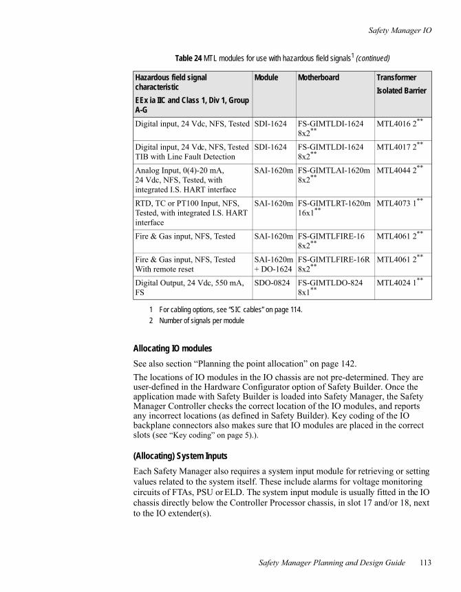
Safety Manager IO
Safety Manager Planning and Design Guide 113
Allocating IO modules
See also section “Planning the point allocation” on page 142.The locations of IO modules in the IO chassis are not pre-determined. They are user-defined in the Hardware Configurator option of Safety Builder. Once the application made with Safety Builder is loaded into Safety Manager, the Safety Manager Controller checks the correct location of the IO modules, and reports any incorrect locations (as defined in Safety Builder). Key coding of the IO backplane connectors also makes sure that IO modules are placed in the correct slots (see “Key coding” on page 5).).
(Allocating) System Inputs
Each Safety Manager also requires a system input module for retrieving or setting values related to the system itself. These include alarms for voltage monitoring circuits of FTAs, PSU or ELD. The system input module is usually fitted in the IO chassis directly below the Controller Processor chassis, in slot 17 and/or 18, next to the IO extender(s).
Digital input, 24 Vdc, NFS, Tested SDI-1624 FS-GIMTLDI-1624 8x2**
MTL4016 2**
Digital input, 24 Vdc, NFS, Tested TIB with Line Fault Detection
SDI-1624 FS-GIMTLDI-1624 8x2**
MTL4017 2**
Analog Input, 0(4)-20 mA, 24 Vdc, NFS, Tested, with integrated I.S. HART interface
SAI-1620m FS-GIMTLAI-1620m 8x2**
MTL4044 2**
RTD, TC or PT100 Input, NFS, Tested, with integrated I.S. HART interface
SAI-1620m FS-GIMTLRT-1620m 16x1**
MTL4073 1**
Fire & Gas input, NFS, Tested SAI-1620m FS-GIMTLFIRE-16 8x2**
MTL4061 2**
Fire & Gas input, NFS, Tested With remote reset
SAI-1620m + DO-1624
FS-GIMTLFIRE-16R 8x2**
MTL4061 2**
Digital Output, 24 Vdc, 550 mA, FS
SDO-0824 FS-GIMTLDO-824 8x1**
MTL4024 1**
1 For cabling options, see “SIC cables” on page 114.2 Number of signals per module
Table 24 MTL modules for use with hazardous field signals1 (continued)
Hazardous field signal characteristic
EEx ia IIC and Class 1, Div 1, Group A-G
Module Motherboard Transformer
Isolated Barrier

5 – Planning the system design
114 Release 152, Issue 1.0
Cabling and FTAs
SIC cables
Types of SIC cables
System Interconnection Cables (SIC) transport field signals from the field terminators to IO modules (and vise versa). Depending on whether FTAs or field terminals are used in the configuration, you use either a SICC cable (type SICC-0001), or a SICP cable (type SICP-0001). Refer to Table 25 on page 114 for input signals and Table 26 on page 114 for output signals.
Lengths of SIC cables
SIC cables are available in the following lengths:3.25 m, 5 m, 6 m, 8 m, 10 m, 15 m, 20 m, 25 m and 30 m.
The lengths of the SIC cables are determined by the location of the field terminals and FTAs. The field terminals and FTAs can be located in the same system as the IO chassis, or in a separate system (marshalling or interface cabinet).
Table 25 Possible ways to connect input field signals to input modules (read table from left to right to see possible interface and wiring options)
Input Signals
Field signal Terminal SICP cable Input module
Field signal Terminal SICP cable Input converter module Input module
Field signal FTA SICC cable Input module
Field signal FTA SICC cable Input converter module Input module
Table 26 Possible ways to connect output field signals to output modules (read table from left to right to see possible interface and wiring options)
Output Signals
Output module SICP cable Terminal Field signal
Output module
Output converter module
SICP cable Terminal Field signal
Output module SICC cable FTA Field signal
Output module
Output converter module
SICC cable FTA Field signal

Cabling and FTAs
Safety Manager Planning and Design Guide 115
COM cablesSafety Manager uses the following communication cables to realize the Computer- and Network infrastructure: (see also General info on communication cables):
• Internal communication cables between Safety Manager communication modules and communication FTAs (DCOM-232/485 for RS232/RS422 and RS485 connections, and UCOM-HSE for Ethernet connection).
• External communication cables between the communication FTAs and external devices or between communication FTAs (DCOM-232/485) installed in other Safety Managers. Connections are possible to:
- Safety Station, Safety Builder
- Experion™ network
- HMI
Table 27 on page 115 shows the maximum distance that can be covered with a specific connection type and speed.
End Of Line (EOL) terminator
An End Of Line (EOL) terminator needs to be placed at both ends of an RS485 communication link. A missing or incorrectly placed EOL terminator can cause communication problems. The cable type determines the resistor value of the End Of Line (EOL) terminator.
Table 27 Maximum distances for different communication protocols and speed
Connection Speed Maximum distance
Full-duplex Half-duplex
RS232 38k4 15 m
RS422/485 115Kb 1 km 500 m
1 Mb 120 m 60 m
2Mb 60 m 30 m
4 Mb 30 m 15 m
Ethernet 100 Mb 100 m
FO 2 Mb 1 km1
1 Cable quality can impact maximum distance

5 – Planning the system design
116 Release 152, Issue 1.0
IO FTAsA Field Termination Assembly (FTA) module is the interface between field components (such as sensors or valves) and IO modules in Safety Manager.
An FTA module converts input field signals to values appropriate for the Safety Manager input module that is used, or Safety Manager output module signals to values suitable for the field. To enable this signal conversion, FTAs can be used in combination with input converter modules or output converter modules.
Which FTA to use in case of a specific field signal is shown in Table 21 on page 110.
Detailed information on IO FTAs can be found in Field Termination Assembly modules.
COM FTAsThe communication FTA DCOM-232/485 is the combined RS232/485 communication interface of Safety Manager. It provides Safety Manager with a RS485/422 or a RS232 connection.
The communication FTA UCOM-HSE is used for Ethernet connections.
The following needs to be considered regarding communication FTAs:
• Always use two UCOM-HSE for Ethernet connections, one for each link.
• Use the UCOM-HSE in combination with power distribution module PDB-HSE24 to guarantee 6 kV isolation between redundant network A and B (FTE).
• Fiber Optics (F.O.) converters are third party equipment, used to increase the maximum possible distance for RS232 and RS485 communication.The first F.O. converter converts the RS232/485 signals to fiber optics signals, which allows for communication over larger distances. After covering this large distance, the second F.O. converter converts the fiber optics signals back to RS232/485 signals.
Detailed information on COM FTAs can be found in Field Termination Assembly modules.
Location of FTAsThe FTA locations are as follows:
• IO FTAs: marshalling cabinet or marshalling section in system cabinet.
• COM FTAs: system cabinet.

Cabling and FTAs
Safety Manager Planning and Design Guide 117
When IO FTAs are located in non-Safety Manager cabinets, the engineering department must provide type numbers, data sheets and schematic diagrams of the used FTAs to the vendor of the cabinet, panels etc.
Field cablesThis section discusses main items that should be considered when planning field cables for IO or communication.
IO signal field cables
Cable length
When deciding on IO signal field cables, cable losses must be accounted for.
When using excessive long cables, Safety Manager field devices may experience voltage drops due to copper losses. You can compensate voltage drops with the following options:
1. Increase wire diameter. For maximum diameter see Field Termination Assembly modules
2. Increase DC voltage, close to the maximum range of Safety Manager IO. For details see Safety Manager operating conditions.
Shielding IO signal cables
All cables carrying analog signals must be shielded. For details see Shielded field cables.
Communication field cables
Cable length
To determine the maximum cable length, see Table 27 on page 115.
Cable type/shielding
The following cable types are recommended in combination with the cable lengths as defined in Table 27 on page 115:
Note:
If you choose option 2, make sure the power supply is stable. For detail see “Power concept” on page 119.

5 – Competences and precautions
118 Release 152, Issue 1.0
• RS232 and RS485 Recommended: Belden type 8103 3x2 CORE SHIELD
• Ethernet Recommended: CAT5PLUS Shielded Twisted Pair (STP)
Routing field cables
Cables and wires carrying different voltages must be routed as follows:
The following cables and wires must be routed separately:
• AC voltages must be routed separately from DC voltages.
• Wires and cables carrying communication signals must be routed separately from voltage-carrying wires and cables.
• Communication cables (typically ethernet cables, RS485 and RS232 cables) may cross voltage-carrying wires but they may not be routed together.
• 5 Vdc cables and IO bus flatcables which are routed to an adjacent Safety Manager cabinet must be separated from other cables or wires routed to these cabinets.
Fiber optic cables may be routed with other cables, but only in such a way that they are not exposed to physical stress.
Table 28 Routing of cables carrying different voltages
Voltage cable Requirements
5 Vdc These cables must be routed separately from other voltages.
24 Vdc, 48 Vdc These cables may be routed together.
110 Vdc

Power concept
Safety Manager Planning and Design Guide 119
Power concept
Calculating power consumption and heat dissipationPower consumption and heat dissipation have to be calculated to determine the capacity of the power supply and the type and capacity of temperature management system (fans per default).
You are advised to use the “Power Consumption and Heat Dissipation Calculation” tool of Honeywell SMS to calculate both.
Power consumption
Power consumption needs to be calculated to determine the required capacity of the power supply. Power consumption can be divided into two groups:
• Internal power consumption Power consumed by the CP modules and the electronics on the IO modules.
• External power consumption Power which is required by the field and is fed through the IO modules, FTAs, third party equipment etc. to consumers oustide the cabinet.
Heat dissipation versus operating temperature
The operating temperature range of Safety Manager must remain between –5°C—70°C (23°F—158°F).
The “Power Consumption and Heat Dissipation Calculation” tool of Honeywell SMS operating temperature of Safety Manager combines 3 factors:
1. Ambient temperature of the cabinet enclosure
2. Heat dissipation or internal power consumption
3. Installed temperature management system (e.g. fans)
Note
The power consumption mentioned in this section is related to a fully equipped Safety Manager system, which can span more than one cabinet.The following items should always be taken into account when calculating the power consumption of an Safety Manager system:• Spare installed and spare prewired IO• Third party and free issue equipment (even though it will not be powered up and
tested).

5 – Planning the system design
120 Release 152, Issue 1.0
The heat dissipation must be calculated to determine if and what measures are required to ensure that:
• the maximum operating temperature is not exceeded
• the operating temperature does not drop below the minimum temperature.
Planning the power supplyThe required AC and/or DC voltage levels differ per Safety Manager configuration and hardware requirements.
However, Safety Manager requires at least 24 Vdc and 5 Vdc supply voltages:
• 24 Vdc is required to power the Controller.
• 5 Vdc (converted from 24 Vdc by the PSU-240516) is required for internal power of the Control Processor modules and IO modules.
The PSU-240516 is a (TUV-approved) 24 Vdc / 5 Vdc Power Supply Unit and is installed in the Controller chassis.
Field devices are typically powered via Safety Manager IO modules.
The voltage level (24 Vdc, 48 Vdc or 110 Vdc) required to power the IO modules depends on the type of IO modules. This voltage will also be used to power the field devices. Exceptions to this rule are field devices that need 115 Vac to 280 Vac.
The power to Safety Manager is delivered by power supply feeders that may feed the cabinet directly or via power supply units. It is the responsibility of the customer to arrange for power supply feeders of sufficient capacity for Safety Manager (AC and/or DC).
There are three options for incoming power/feeders:
• AC power provided to Safety Manager (page 120)
• DC power provided to Safety Manager (page 123)
• A combination of the above
According to the IEC 61010 the voltage level and, if applicable, frequency of all power feeders and Power Supply Units should be indicated in the Power Distribution Drawings that accompany the FDS.
Planning AC power supply
The load, the PSU configuration, the required spare capacity and the number of incoming AC power feeders, determine together howmany PSUs are required.
Table 29 on page 121 shows the approved power supply units (PSUs) available for new Safety Manager projects.

Power concept
Safety Manager Planning and Design Guide 121
Number of power supply units
The number of power supply units that is required depends on the power consumption of the system and the chosen PSU configuration (see “PSU architectures” on page 124).
The maximum output current of a PSU depends on its type and derating curve (current and percentage versus the PSU ambient temperature).
Example To determine the number of PSUs required the following information is needed:
• The total load required by Safety Manager, e.g. 70 A.
• The type of power supply units used, e.g. PSU-UNI2450.
• The PSU ambient temperature variation, e.g. between -5°C and 70°C (23°F and 158°F). The spare power supply requirement, e.g. 25%.
The maximum output current of a vertically mounted PSU-UNI2450 power supply unit is 48 A up to +50ºC (122°F) and 24 A up to 70ºC (158°F). So, in this example, the number of required PSUs is (70 x 1.25)/24 = 4 (actually 3.65).
This calculated number equals “N” in the different PSU architectures as described in “PSU architectures” on page 124. The actual number of PSUs used can be N, N+1 or 2N, depending on the chosen architecture.
Table 29 Safety Manager power supply units
Type Input Output See:
PSU-UNI2450 110-240 Vac 25 Vdc, 48 A28 Vdc, 43 A
“PSU-UNI2450” on page 16
1200 S 48 P067 100-132 Vac, 200-264 Vac 48 Vdc, 25 A -
SM 120-13 90-265 Vac 110 Vdc, 13 A -
Note
These power supply units are TUV approved. Only these power supply units can be used in Safety Manager for TUV-compliant applications. They are also strongly recommended for applications that do not require TUV approval.

5 – Planning the system design
122 Release 152, Issue 1.0
Circuit breakers and disconnectors
IEC 61010 requires that all powered devices can be fully isolated.
This means that all consumers inside a cabinet, such as enlosure lights and outlet sockets must be equipped with a means to allow disconnection from the power grid.
• Auxiliary equipment, such as enclosure lights and outlet sockets, must be powered via a double pole circuit breaker.
• Power supply units must have means to disconnect them from the power grid. Depending on the type of power supply used, circuit breakers and or disconnectors may be required or can be left out:
- The PSU-UNI2450 power supply unit is equipped with AC and DC power plugs with locking mechanisms. In case of failure of a PSU-UNI2450 these power plugs can be extracted and the PSU replaced without risking a short or electrical shock. Dedicated main circuit breakers or fused terminals are not required on either side of the PSU and therefore not recommended.
- Other power supply unit types are equipped with power terminals.To prevent the risk of a short or electrical shock while performing maintenance on these power supplies dedicated circuit breakers are required on the AC side and disconnectors on the DC side.In case of maintenance the circuit breaker and disconnector of a PSU can be opened to allow for a safe (dis)connection of a power feeder.
The size of the AC main (primary) circuit breaker or fused terminals must be sufficient to fit the load and the incoming AC power feeder cable diameter.
Auxiliary equipment
Customer requirements can demand the installation of auxiliary equipment, such as:
• Enclosure lights (110 Vac / 230 Vac)
• Outlet sockets (110 Vac / 230 Vac)
• Fiber optic converters (24 Vdc / 110 Vac / 230 Vac)
Note:
Circuit breakers and fuses have a relatively low mean time between failure (MTBF).To increase availability of the power supplies it is recommended to reduce the number of s/fuses to a minimum.

Power concept
Safety Manager Planning and Design Guide 123
Enclosure lights and outlet sockets are considered non-vital auxiliary equipment. If the power feeder to these devices fails, the operation of Safety Manager is not affected.
Fiber optic converters are considered to be vital auxiliary equipment. If the power feeder to these devices fails, the operation of Safety Manager is not affected if it is configured in a redundant architecture.
Planning DC power supply
If a customer provides DC power feeder(s) for Safety Manager, power supply units (PSUs) may not be required.
Since Safety Manager needs 24 Vdc to operate, at least one DC feeder must supply 24 Vdc. When this is not the case, additional equipment is required to transform the offered power to 24 Vdc.
For outputs that require a different voltage level than 24 Vdc, the customer can provide separate feeders. The voltages of these feeders do not need to be converted.
The incoming DC power feeder cables can be connected to:
• redundant power feeder units (for 24 Vdc and 48 Vdc)
• Main circuit breakers(The use of main circuit breakers is the preferred option.)
• Fused terminals
• Power distribution rails
From here, the power is directed to dedicated power distribution rails which allow connection of various consumers.
Supply voltages
The following DC supply voltage ranges apply to ensure correct operation of the Safety Manager modules:
• 110 Vdc: +25% / –15%
• 48 Vdc: +15% / –15%
• 24 Vdc: +30% / –15%

5 – Planning the system design
124 Release 152, Issue 1.0
PSU architectures
Architectures for AC/DC power supply units
PSUs are selected to supply sufficient power to Safety Manager. A more fault tolerant system is achieved when more PSUs are installed than needed to deliver the required power.
The maximum output current of the PSU depends on its type and derating curve (maximum capacity versus PSU ambient temperature).
Depending on the load, the required spare capacity and the number of incoming power feeders (110 or 230 Vac), several PSUs may have to be installed. When more power is required than one PSU can deliver, PSUs can be wired parallel to deliver the total power.
Depending on the Safety Manager configuration, three PSU configurations can commonly be chosen:
• Non-redundant (N configuration)
• Redundant (N+1 configuration)
• Fully redundant (Nx2 configuration)
Where N equals the number of PSUs required by Safety Manager.
Notes:1. If it cannot be guaranteed that the DC power supplied to Safety Manager remains
within the above ranges, additional voltage monitoring is required.2. It is assumed that the 24Vdc Plant power fed to the SM Controller is uninterrupted. If
not, means should be provided to avoid power dips at the 24Vdc lines to the SM Controller.
3. When using Plant power, the Plant power supply must fulfill the requirements as laid down in IEC 61010 or IEC 60950.
Note:
DC PSUs must fulfill the requirements as laid down in IEC 61010 or IEC 60950.

Power concept
Safety Manager Planning and Design Guide 125
Non-redundant power supply units (N configuration)
In this configuration the number of PSUs chosen matches the required power. If the system has a non-redundant Controller there may be no need for redundancy in the PSU configuration.
AC power feeders supply the power for the entire Safety Manager system. To limit the load on the feeder, you are advised to put no more than 2 power supplies on one feeder.
This configuration has the following characteristics:
• The PSU(s) deliver(s) sufficient power for Safety Manager.
• A failure in one of the PSUs may lead to a system stop with undefined results.
• A failure in the mains power leads to a system stop with undefined results.
See Figure 21 on page 126 for details.
Redundant power supply units (N+1 configuration)
If the system has a redundant Controller, it is recommended to have a PSU configuration that is tolerant to a PSU failure. In the N+1 configuration one extra PSU is placed besides the PSU(s) necessary to deliver the required power.
AC power feeders supply the power for the entire Safety Manager system. To limit the load on the feeder, you are advised to put no more than 2 power supplies on one feeder.
This configuration has the following characteristics:
• The PSUs can supply more power than the Safety Manager system requires.
• System continues normal operation when one PSU fails (single-fault tolerant).
• A failure in the mains power leads to a system stop with undefined results.
See Figure 21 on page 126 for details.
Note
A maximum of two PSUs for each power feeder is recommended for all these PSU architectures. This depends on the inrush current, see PSU-240516. The maximum current per power feeder is normally defined by the user and typically ranges between 10-16 A. This has consequences for the number of power feeders needed to supply power to the PSUs.For example:• 115 V: one power feeder for every PSU-UNI2450• 230 V: one power feeder for every two PSU-UNI2450 PSUsConfigurations for other voltages and PSUs can be calculated using the information shown in Table 29 on page 121.

5 – Planning the system design
126 Release 152, Issue 1.0
Fully redundant power supply units (Nx2 configuration)
If the system has a redundant Controller, it is recommended to have a PSU configuration that is tolerant of a PSU or mains failure. In the Nx2 configuration the required PSU capacity is doubled. The the second part is connected to an independent power feeder system.
AC power feeders supply the power for the entire Safety Manager system. To limit the load on the feeder, you are advised to put no more than 2 power supplies on one feeder.
This configuration has the following characteristics:
• The PSUs can deliver twice the power required by the Safety Manager system.
• System continues normal operation when one PSU fails (single-fault tolerant).
• System continues normal operation upon a failure in the power mains.
See Figure 21 on page 126 for details.
Architectures for DC power supply
If a customer provides DC power feeder(s) for the Safety Manager system, power supply units (PSUs) may not have to be installed. Instead a Honeywell SMS Feeder Unit 24V or Feeder Unit 48V is installed.
Figure 21 Power Supply Units configurations (2 examples for each configuration)
PSU
Feeder 1
PSU
Feeder 2
PSU
Feeder 3
PSU PSU
Feeder 1
PSU
Feeder 2
PSU PSU
Feeder 3
PSU PSU
Feeder 1
PSU
Feeder 2
PSU PSU
Feeder 1
PSU
Feeder 1
PSU
Feeder 2
PSU PSU
Feeder 1
PSU PSU
Feeder 2
N N
N N+ 1 + 1
N N N N
N
N+1
2N

Power concept
Safety Manager Planning and Design Guide 127
If a customer provides one DC power feeder cable for the entire Safety Manager system, a single failure in the mains power leads to a system stop with undefined results.
Redundant DC power feeders are normally supplied with the Safety Manager system. In this case, decoupling diodes have to be used.
The Honeywell SMS Feeder Units already contain decoupling diodes.
Planning feedersThe following issues are important regarding power feeders:
• Connect separate feeders to different power sources to increase availability.
• In case of FGS, two independent power feeders have to be used in compliance with NFPA72 1.5.2:
- Each of the two feeders shall have the capacity to feed the entire system and connected devices.
- The primary feeder shall be one with high reliability (for example UPS).
- The secondary feeder may not be in standby mode: both feeders share the power supply to the system.
• Instead of using the feeder-PSU combination, plant power or external power can be used for 24 Vdc.
Planning Earthing concept and ELD useDepending on the required configuration the system must be floating from earth or connected to earth. An Earth Leakage Detection (ELD) can be used to check if the required (or unwanted) earth connections are present.
Note:
If you intend to use Plant power or external power, please see also “Planning DC power supply” on page 123.

5 – Planning the system design
128 Release 152, Issue 1.0
Earth Leakage Detection can be implemented in the following ways:
Earth connection situation Modules used for ELD
Detecting an unwanted earth connection (earth fault).
In this case, the system is supposed to be floating from earth. In case of an earth connection the risk of an earth loop exists. So, an ELD will warn when a single earth connection is detected between the floating system and earth.
• Dedicated ELD module 10310/1/1• Any IO module with built in ELD
functionality (like SDIL-1608)
Detecting a loss of earth connection.
In the case of Zener barriers an earth connection is wanted. So, an ELD will warn when this earth connection is lost.
• Any IO module with built in ELD functionality (like SDIL-1608)

Third party equipment
Safety Manager Planning and Design Guide 129
Third party equipmentSome projects require free-issue equipment and/or third-party equipment to be installed in Safety Manager.
Third party equipment is bought by the integrator and installed in Safety Manager as any other piece of hardware.
Third party equipment and free-issue equipment must always be taken into account when calculating the power consumption of Safety Manager.
Free-issue equipment is installed in Safety Manager on request of the customer and is not bought by the integrator.
The supplier of the equipment (third party or free-issue) should provide user instructions and installation instructions, which should be followed closely during the design and construction of Safety Manager.
Concerning free-issue equipment
All free-issue equipment has to be recorded in the logbook for engineering.
Free-issue-equipment is not powered up or tested during the internal acceptance test (IAT) of the Safety Manager cabinet because it is not purchased by the integrator. Only the wiring to and from the free-issue equipment will be tested.
Free issue equipment must always be taken into account when calculating power consumption of Safety Manager.
During the Customer Acceptance Test (CAT) the supplier of the free-issue equipment, the customer or the customer representative will have the opportunity to test the equipment.
Note
If free-issue equipment or third-party devices have to be installed in Safety Manager and CE conformity is required, the engineer must ensure that this equipment has a valid Declaration of Conformity (DoC) according to the EMC standard as mentioned in the CE Guidelines (Honeywell SMS document number FS99-503).

5 – Planning the system design
130 Release 152, Issue 1.0
System cabinets
Planning the cabinet layoutThis section describes the general considerations for planning the cabinet layout. The cabinet layout indicates the positions of Controller chassis, IO chassis, rails, cable ducts, power supply units, doors, etc. It differs per project, depending on project-related specifications.
All cabinet-related hardware specifications must be defined in the Functional Design Specification (see: “Developing the Functional Design Specification (FDS)” on page 25). The Cabinet Layout Drawings that accompany the FDS are a graphical representation of the hardware in the cabinet.
Cabinet types
The preferred cabinet for Safety Manager is the Rittal TS 8808 cabinet. Its dimensions are: 80 x 80 x 200 cm (width x depth x height). However, it is possible to use a different type of Rittal cabinet or a cabinet from a different manufacturer if customer configurations or preference require so.
The weight of the Safety Manager cabinet varies with installed options and can go as high as 550 kg (1210 lbs) per Rittal cabinet. Make sure that the customer or customer representative is informed in time so that proper arrangements can be made for transportation and placement of the cabinet on site.
Standard cabinets
Together with Rittal, Honeywell SMS defined a number of standard cabinet setups. These cabinets, called BCU (Basic Cabinet Unit), have the following options:
• 6 types of Cabinet access (shown in Table 30 on page 136) having combinations of:
- Front access or front and rear access
- Full doors or half doors
- Turning points on the left or right side, for both front and rear doors
• Swing frame installed or no swing frame installed (option for all 6 access types)
• Plinth or no plinth(option for all 6 access types)
Given these options, 24 different BCUs are possible.

System cabinets
Safety Manager Planning and Design Guide 131
Each BCU type has a specific part number and can be ordered from Honeywell SMS.
Combining Safety Manager cabinets
Figure 22 on page 131 shows that the maximum number of Safety Manager cabinets that can be built together is four. Dedicated PSU and/or marshalling cabinets can be placed on either side of this combination.
This number:
• excludes dedicated PSU and marshalling cabinets and
• also depends on the equipment mounted in the cabinets, the total weight of the cabinets, and the customer requirements.
A maximum number of three Rittal cabinets can be built together and transported as one shipping section.
Note
In quotations and schedules, you should always account for additional costs and additional delivery time for non-standard options.
Figure 22 Example of four cabinets built together

5 – Planning the system design
132 Release 152, Issue 1.0
In the case of multiple cabinets, there will never be more than two IO cabinets on either side of the CP cabinet.
Example
In the case of three IO cabinets, the CP cabinet has to be placed in the “middle”, with two IO cabinets on one side and the third cabinet on the other side.
Marshalling cabinets can be placed left or right from the row of cabinets.
Power distribution and IO connections between Safety Manager cabinets require special cabling.
Ingress Protection (IP) rating
By default, Safety Manager cabinets have an Ingress Protection (IP) rating of IP20 in accordance with DIN VDE 0470.
If specifically indicated in the customer requirements, this IP rating can be increased by taking additional measures.
Swingframe layout
A Safety Manager cabinet usually contains a swingframe where the Controller chassis and the IO chassis are placed.
The height of the swingframe is 40 HE.
Typically, the Controller chassis is placed 3 HE below the top position in the swingframe. Below the Controller chassis up to 8 IO chassis can be placed.
A swingframe that only contains IO modules can fit 9 IO chassis. The top IO chassis is placed 3 HE below the top position in the cabinet.
Figure 23 on page 133 and Figure 24 on page 134 show different layouts for typical Safety Manager cabinets.
For specifications and details on Safety Manager cabinets, see: Cabinet.
Note
In quotations, you should always account for additional costs and additional delivery time due to measures required to increase the IP rating.
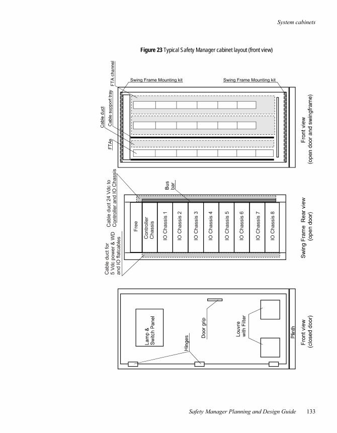
System cabinets
Safety Manager Planning and Design Guide 133
Figure 23 Typical Safety Manager cabinet layout (front view)
Swing Frame Mounting kitSwing Frame Mounting kit
Con
trolle
rC
hass
is
IO C
hass
is 1
IO C
hass
is 2
IO C
hass
is 3
IO C
hass
is 4
IO C
hass
is 5
IO C
hass
is 6
IO C
hass
is 7
IO C
hass
is 8
Cab
le d
uct 2
4 V
dc to
Con
trolle
r and
IO C
hass
isC
a ble
duc
t fo r
5
Vdc
p ow
er &
WD
and
IO fl
atca
b les

5 – Planning the system design
134 Release 152, Issue 1.0
Figure 24 Typical Safety Manager cabinet layout (side and top view)
Front door
Swing frame withController Chassis
Back door
FTAs and Terminals
FTAchannel
lifting eye bolts
Cut-out for Fans
Roof Panel with Fan Cutout
Top view (without roof)
Left hand side view
Swing Frame
IO Chassis
Cableducts
Swing FrameTurning point
Support Structures
Controller Chassis

System cabinets
Safety Manager Planning and Design Guide 135
Planning cabinet-related hardwareA cabinet contains the following components:
Cabinet access
Because of Electro Magnetic Charging (EMC) directives Safety Manager is mounted inside a cabinet. By default, a front door is mounted to enable access to the system. If the cabinet is not placed against a wall, it can also have rear access. Rear access options have to be discussed with the customer.
There are two standard door types:
• Full (single) door; one door mounted at one side (front or rear) of the cabinet
• Double (half) doors, two doors mounted at one side (front or rear) of the cabinet
Table 30 on page 136 shows all combinations of these door types for a standard Safety Manager cabinet.
Component Standard or optional
Cabinet access (door types) optional
Lifting eye bolts standard
Plinths optional
ESD bonding point standard
Fans standard1
1 Forced airflow is required for proper temperature management.
Louvers / filters optional
Thermostat optional2
2 A thermostat is required if the installed fan does not have automatic fan failure detection. If a Honeywell SMS Fan Unit (which contains fan failure detection) is used, a thermostat is not required.
Cable entry optional
Support structures standard
Note
Any standard Rittal door and side panel may be used. But if CE marking is required, steel doors, steel back walls and steel side panels are mandatory.For detailed information on the CE requirements refer to the CE Guidelines (Honeywell SMS document number FS99-503).

5 – Planning the system design
136 Release 152, Issue 1.0
The turning points of the doors can be placed at either side. This option has to be discussed with the customer since the location of turning points is chosen to prevent obstruction of escape routes. This means the door must close in the walking direction to an emergency exit.
A standard full front door has its turning point at the left side, as the swing frame has its turning point at that side as well. Access type (front/rear, single/double) and turning points must be indicated in the Cabinet Layout Drawings accompanying the FDS.
Rittal does not supply standard viewing doors for the TS series cabinet.
Table 30 Cabinet access options of standard Safety Manager cabinets
Front door Rear door Code in figure below
Front access only Single, hinged left - 1000
Single, hinged right - 0100
Double - 1100
Front and rear access Single, hinged left Single, hinged right 1001
Single, hinged right Single, hinged left 0110
Double Double 1111
Please note the following issues:• A combination of single (full) door and double (half) doors is not possible.• Double (half) doors for rear entry can only be selected if double (half) doors have been
selected for front entry.• Single (full) rear door, hinged on the left hand side can only be selected if a single
(full) front door, hinged on the right hand side has been selected.• Single (full) rear door, hinged on the right hand side can only be selected if a single
(full) front door, hinged on the left hand side has been selected.
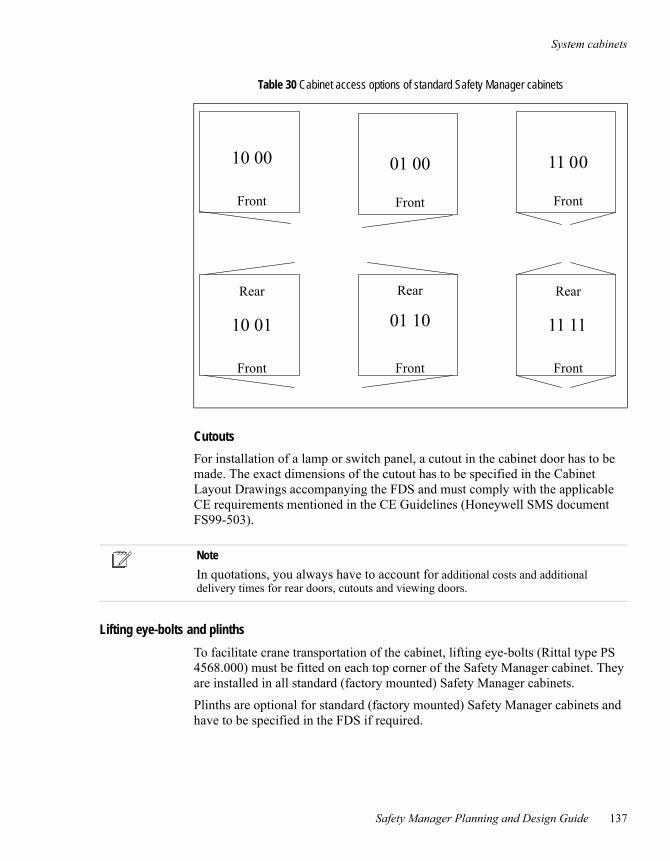
System cabinets
Safety Manager Planning and Design Guide 137
Cutouts
For installation of a lamp or switch panel, a cutout in the cabinet door has to be made. The exact dimensions of the cutout has to be specified in the Cabinet Layout Drawings accompanying the FDS and must comply with the applicable CE requirements mentioned in the CE Guidelines (Honeywell SMS document FS99-503).
Lifting eye-bolts and plinths
To facilitate crane transportation of the cabinet, lifting eye-bolts (Rittal type PS 4568.000) must be fitted on each top corner of the Safety Manager cabinet. They are installed in all standard (factory mounted) Safety Manager cabinets.
Plinths are optional for standard (factory mounted) Safety Manager cabinets and have to be specified in the FDS if required.
Table 30 Cabinet access options of standard Safety Manager cabinets
Front Front Front
10 00 01 00 11 00
Rear
01 1010 01
Rear
11 11
Front Front Front
Rear
Note
In quotations, you always have to account for additional costs and additional delivery times for rear doors, cutouts and viewing doors.

5 – Planning the system design
138 Release 152, Issue 1.0
Power supplies
The power supplies are located inside the cabinet at the front side. If the front side space is not sufficient to accommodate the power supplies, other power supplies have to be mounted at the back side. Each side has space for a maximum of four power supplies, so in a cabinet a maximum of eight power supplies can be mounted.
ESD bonding point
An Electrostatic Discharge (ESD) bonding point must be fixed to the cabinet chassis. It provides protection against electrostatic discharge when working in the Safety Manager cabinet after the installation of electronic parts.
Fans, louvers and filters
To ensure a sufficient cooling of the Safety Manager cabinet, you have to calculate the total heat dissipation of the cabinet. This calculation indicates the number of fans required in the cabinet to ensure the temperature in the cabinet stays within safe limits.
The Honeywell SMS Fan Unit is mounted in the cabinet roof by default.
It consists of two redundant fans and has a read back contact that indicates the operational status of the fans. The read-back contact of the fan unit is wired to the system FTA.
Louvers and filters can be mounted at the bottom of the cabinet doors to allow for airflow through the Safety Manager cabinet.
Cable entry
The following cables can enter the cabinet, if required:
• Earth/ground cables
• Power feeder cables
• Communication cables
• Field cables
• System interconnect cables
Depending on customer requirements, these cables can enter the cabinet from the top and/or bottom.
Note
If the operating temperature exceeds the specified shutdown limit (set during system configuration), the Control Processor in which the temperature is measured stops.

System cabinets
Safety Manager Planning and Design Guide 139
Auxiliary equipment
Customer requirements may demand installation of auxiliary equipment, such as:
• Enclosure lights (110 Vac / 230 Vac)
• Outlet sockets (110 Vac / 230 Vac)
• Fiber optic converters (24 Vdc / 110 Vac / 230 Vac)
Support structures
The Safety Manager cabinet contains general mounting rails as support structures for cables, cable trays, and so on (typically Rittal TS 8612 rails).
In addition, various secondary support structures can be attached to the mounting rails:
• FTA-related support structure (typically a Rittal TS35 rail)
• Cable ductsCable ducts need to be big enough to accommodate the number of wires or cables routed through the duct.
• Mounting plates for power supply units.
Cable support/clamp rail
The standard Safety Manager cabinet includes a cable support and clamp rails for securing field cables by means of cable clamps. The clamping devices must be able to withstand a 45 kg (100 lbs) pull to prevent damage to the cabinet during the pulling of externally fastened cables.
Customer requirements can make it possible that cable support and clamp rails are not mounted. For example: When a cable support and clamp rail is mounted below the false floor on which the cabinet is placed.
Note
Bottom cable entry is standard.The type of cable entry has a major impact on the cabinet layout, so it must be specified in the FDS (see “Developing the Functional Design Specification (FDS)” on page 25) and confirmed as early in the project as possible.

5 – Planning the system design
140 Release 152, Issue 1.0
Planning cabinet packaging and deliveryWhen planning cabinet delivery, keep in mind that the cabinet can be transported by land, sea or air.
The following types of packaging can be chosen:
• pallet and carton
• crate
• sea-proof (option with the highest costs)

Safety Manager Planning and Design Guide 141
6Planning the application design
The application used in Safety Manager can be divided in the following parts:
• Point allocation
• Logical connection configuration
• Functional logic design
• Application verification
All can be carried out by using the Safety Builder. When a point database is available, network configuration and functional logic design can be performed simultaneously.
This chapter describes the activities for planning the various stages of application design:
Attention:
In Hardware Configurator you need to select a QPP-0002 when:• the system will include SM universal IO,• Remote IO A.R.T. will be configured,• Safety Manager must act as Modbus Master.
Topic See
Planning the point allocation page 142
Planning the logical connection configuration page 145
Planning the functional logic design page 146
Application verification page 150

6 – Planning the application design
142 Release 152, Issue 1.0
Planning the point allocationThe Point Configurator in Safety Builder is used to create and allocate points in the application.
For information on using the Point Configurator, see Point Configurator.
Point allocation considerationsWhen planning the point allocation, take the following into consideration:
Safety related points and non safety related points
Points can be safety related or non safety related, depending on their fault reaction settings. Safety related IO points are those that have their fault reaction set to either:
• High
• Low
• Bottom scale
• Top scale
• Fixed value
All other settings are not safety related.
To understand the difference between safety related IO and not safety related IO see Safety Manager fault detection and reaction.
Point allocation for points of SM chassis IO modules
• Safety related points should be allocated to Safe IO modules, and the fault reaction for these modules should be set to high, low, bottom scale, top scale or fixed value.
• Non safety related points can be allocated to non-safe or Safe IO modules, but the fault reaction for these modules should not be set to high, low, bottom scale, top scale or fixed value.
Note:
Fault reaction is set per Point, except for digital output Points (DO) of chassis IO modules where fault reaction is applied per module.

Planning the point allocation
Safety Manager Planning and Design Guide 143
Point allocation for points of SM universal IO modules
Each channel of a SM universal IO module can be configured individually in Safety Builder. Settings such Safety related can be allocated as required.
Dividing points over IO modules and IO chassis
• Since each IO chassis has only one internal power supply (for example 24 Vdc), it is not possible to combine IO modules of different voltages (24, 48, or 110 Vdc) in the same IO chassis.
• Points that are part of a voting configuration (for example 3 inputs with a 2oo3 voting) should be divided over separate IO modules (in this case, 3 IO modules) which can be located in the same IO chassis.
Module redundancy
• All SM chassis IO and SM universal IO module types are suitable for redundant IO architectures, provided the SM Controller is also redundant.
Channel grouping
The IO channels on some IO modules are divided in two groups. If an output group has one channel failure or two short circuits then the Control Processor will set that group to a safe state. When both groups of an output card have a failure the Control Processor(s) will stop. If the faults are the result of an error in the field, then both Control Processors (redundant configuration) will stop.
Output load
Consult the Output load, current limiting and supply voltage for information on the limitations on output load for high power modules and the IO chassis as a whole.
Allocation of spare IO
Attention:
This topic applies to chassis IO hardware only.
Note:
The customer determines the required amount of spare IO (installed and prewired).If the customer did not include requirements for spare IO, this should be discussed. Keep in mind that an amount of 20% spare IO is recommended.

6 – Planning the application design
144 Release 152, Issue 1.0
For detailed description of the types of spare IO, see “Spare capacity for SM chassis IO (also referred to as chassis IO)” on page 28.
• Spare installed IO: Allocate all IO modules, cabling and FTAs needed for the spare installed IO.
• Spare prewired IO: Allocate all IO chassis, cabling and FTAs needed for the spare prewired IO.
• Spare IO slot space: Reserve space for spare IO, spare PSU, spare FTA etc.
Importing a point databaseTo speed-up the process of configuring large quantities of points and avoid typing errors you can import points and point properties from databases outside Safety Builder.
To realize this Safety Builder gives you the option to:
• export a point database to external database applications.
• import a point database from external database applications.
With an exported point database open in an external application you can:
• easily modify existing points by modifying exported point properties before re-importing the point database.
• quickly create or add new points to the point database by adding them into the exported point database.
• easily apply identical properties to new created points by copying existing points properties onto the new created points.
See Import and Export to learn more about the formats and properties of external point databases.
Duplicate and unallocated Points When importing FLDs from other systems, duplicate points get a prefix upon import.
When importing points with an imported FLD, these points will be unallocated.
For more information see “The Import FLDs function” on page 149.
Tip
You can export an empty point database to serve as a template in the external database file.

Planning the logical connection configuration
Safety Manager Planning and Design Guide 145
Planning the logical connection configurationThe Network Configurator in Safety Builder is used to configure the network layout of the safety system.
For information on using the Network Configurator, see Network Configurator.
Before starting on the logical connection configuration, the physical network has to be planned and designed (see “Planning the computer- and network infrastructure” on page 55 for further details).
When configuring the logical connections, take the following into consideration:
Experion network
• An Experion™ server can only communicate with direct physically connected Safety Managers.
• Experion communication uses the Ethernet protocol.

6 – Planning the application design
146 Release 152, Issue 1.0
Planning the functional logic designThe Application Editor in Safety Builder is used to create and import FLDs in the application.
For more information about using the Application Editor see Application Editor.
FLD design considerationsFLDs must be designed according to IEC 61131-3 (see the example FLD in Figure 25 on page 146).
The FLDs can be designed by the following parties:
• Honeywell SMS Project Services
• Customer
• Engineering Contractor
Please note that application knowledge and training in application design, network configuration and system configuration is required to be able to design FLDs.
Figure 25 Example of an FLD

Planning the functional logic design
Safety Manager Planning and Design Guide 147
Specifications needed to design and create the FLDs can be found in (amongst others) the following documents:
• Cause and Effect (C&E) Diagrams
• Process & Instrumentation Diagrams (P&IDs)
• Safety Narratives
• Copy template FLDs
Standard functions in the FLD library allow easy integration of (amongst others):
• Alarm functions
• MOS & OOS sensor handling
• Valve stroke testing
• Motor control functions
• Protection against calculation errors
• Fire and Gas sensor handling
Special application design guides and FLD libraries are available for certain types of applications. Please contact Honeywell SMS for details.
Examples of these special applications are:
• Emergency Shutdown (ESD)
• Burner Management Systems (see the BMS manual)
• Fire and Gas (see the F&G manual)
Information required
The following information is required before the actual design of the FLDs and system configuration can start:
Attention:
Be aware that individual FLD’s can be password protected. When an FLD is protected, you can only access and handle it by entering the correct password.Precondition: In Network Configurator, SM Controller properties (physical) - tab: General, IP protection enabled 1 must be selected. For more information: see the Software Reference.
1 IP stands for Industrial Property

6 – Planning the application design
148 Release 152, Issue 1.0
Information / Document Explanation
Functional Design Specification (FDS)
See: “Developing the Functional Design Specification (FDS)” on page 25.
Software Detailed Design Specification (SDDS)
See: “Developing the Software Detailed Design Specification (SDDS)” on page 32
Logic operation type Choose between ESD and F&G logic (normally energized or de-energized).
Cause & Effect (C&E) Diagrams
The C&E diagrams show the cause and effect list in a table layout. The inputs are the causes, the outputs are the effects. The C&E diagrams are generally provided by customer.
Process & Instrumentation Diagrams (P&IDs)
P&IDs are drawings which show the relations between instrumentation devices. All point numbers are listed in the P&IDs.
Narratives Narratives are documents which describe the functionality of the process. Information on timer settings, engineering units, etc. can be found in the narratives.
Flow Diagrams Flow diagrams (together with narratives) can help to understand how the process has to be controlled. In general, flow diagrams are used for applications with a certain sequence and startup procedure. They are often used for batch logic.
Documentation for redraw The customer has already designed and drawn the FLDs, using other software (for example AutoCAD). The designed FLDs have to be redrawn in Safety Builder.
MOS/OOS/Bypass information (1ooN/2ooN)
Depending on the application, Operation Override Switches (OOSs), Maintenance Override Switches (MOSs) or Bypass signals may be available. The predefined FLD solutions chosen for overrides must be included in the PAS.
Trip settings of analog inputs Trip settings are setpoints on analog input signals when an executive action or alarm is required. Information used in the FLDs is required. Trip settings typically depend on the type of logic (ESD or F&G).
System alarms System alarms may be used in the FLDs.Information is required for:• Alarm markers• Diagnostic status of specific safety-related IO
channels• Watchdog status of safety-related output modules

Planning the functional logic design
Safety Manager Planning and Design Guide 149
Creating the logic
When all information for designing the logic is available, the FLDs can be created with the Application Editor of Safety Builder.
All specific logic functions are described in function blocks that are, depending on the project, included in the SDDS, the FDS or the template FLDs. All logic has to be created based on the available information (see: “Information required” on page 147) or copied from a FLD library with the copy FLD function.
The Import FLDs functionImport FLDs is a function in the Application Editor that allows you to import multiple FLDs from e.g. a master plant or a template library.
To import FLDs you must meet the following prerequisites:
• An imported FLD can involve function or equation blocks. When imported, the FLD numbers of these blocks must be free on the target system.
• An imported FLD can be imported with or without Point IDs. When choosing with Point IDs, all duplicate Points are given a prefix upon import.
For more information see Copying an FLD and Importing FLDs.
Special functions Some processes require special safety instrumented functions such as ramping, middle values or motor drivers. The FLD solutions for these functions must be included in the PAS.
Information / Document Explanation (continued)
Attention:
Be aware that individual FLD’s can be password protected. When an FLD is protected, you can only access and handle it by entering the correct password. In case you want to handle multiple FLD’s, only unprotected FLD’s will be listed.Precondition: In Network Configurator, SM Controller properties (physical) - tab: General, IP protection enabled 1 must be selected. For more information: see the Software Reference.
1 IP stands for Industrial Property

6 – Planning the application design
150 Release 152, Issue 1.0
Application verification
Introduction
Throughout the application design, several verification steps must be performed to guarantee the actual configuration and application software in Safety Manager meet the safety requirements of the process.
IO signal configuration
The Print option of Safety Builder allows the user to create hard copies of the IO signal configuration as stored in the application database.
The hardcopy must be reviewed to verify that the signal configuration represents the originally defined configuration.
This review may be concentrated on the safety-related configuration aspects, such as the point qualification, the fault reaction, force enable, hardware allocation and power-on values.
This activity covers the following aspects:
• Data entry by the design engineer.
• System response conform settings in the Hardware Configurator and Point Configurator of Safety Builder.
• Operation of the Safety Station.
Depending on local legislation, the IO signal configuration may need to be approved by an independent certification body, for example TÜV.
Functional logic diagrams (FLDs)
The Print option of Safety Builder also allows the user to create hard copies of the functional logic diagrams as stored in the application database. The hardcopy must be reviewed to verify that the functional logic diagrams represent the intended safeguarding strategy.
This activity covers the following aspects:
• Data entry by the design engineer.
• Operation of the Application Editor of Safety Builder.
Depending on local legislation, the functional logic diagrams may need to be approved by an independent certification body, for example TÜV.

Application verification
Safety Manager Planning and Design Guide 151
Application software
After the application has been successfully compiled and the application software has been loaded into the SM Controller, the correct operation of the application must be verified via a functional test by Engineering.
Functional test
Functional testing is done via the Application Viewer and a means to simulate inputs (e.g. with a switch box or by forcing), and monitor the outputs (e.g. by means of LEDs).
In the Application Viewer the assessor can verify the inputs and application response.
Verify load diagnostics
The Safety Manager File is stored in the SM Controller with the Controller Management function of Safety Builder. After storing, Controller Management reads the diagnostics and checks if the file is correctly stored.
Additionally, a Factory Acceptance Test (FAT) must be performed. During the FAT the IO allocation, safety application and communication are tested. This is required to comply with the safety requirements. Also, the customer verifies if the original requirements have been correctly implemented.
Similar testing may also be done during the start-up and commissioning stages.
Tip
During creation of an application, Engineering can make use of either UniSim® or the TÜV approved Simulation mode of Safety Manager to verify the application. Simulation mode is selected in Safety Builder and requires Control Processor hardware (such as a Training and Simulation Unit) that matches the actual Control Processor configuration. For more details see: The Software Reference.

6 – Planning the application design
152 Release 152, Issue 1.0

Safety Manager Planning and Design Guide 153
7Planning modifications
This chapter describes the planning of replacements, changes and upgrades of hardware and/or software components in an operational Safety Manager.
The following topics are described:
Topic See
Modifications: upgrades and changes page 154
Competencies of people page 158
Precautions when working on Safety Managers page 159
Planning hardware modifications page 161
Planning software modifications page 164

7 – Planning modifications
154 Release 152, Issue 1.0
Modifications: upgrades and changesWhen Safety Manager is operational, the following modifications can be performed to change or improve the functionality of the system:
• upgradeA specific part of the system is replaced by a part with additional functionality, but this functionality is not yet used. Performance may improve though. An upgrade has no implications for the application.
• change (Compile and Load Application needed) New functionality is added to the system, either by using new functionality of an already installed piece of hardware/software or by adding a new piece of hardware/software. This type of change always has implications for the application.
• change (Publish Application needed) No new functionality is added to the system, but ‘documentation only’ data has been changed (e.g. Tag Numbers). Publish Application does not include compiling and loading and can be performed for redundant and non-redundant controllers. This type of change has no implications for the application.
Offline modificationsThe safest way of performing modifications is offline, which is the only way for systems with a non-redundant Controller. Some modifications are too risky to do online. Whether or not it is recommended to do them online has to be considered for each individual case.
Note
Upgrades and changes are referred to as modifications.
Important
It is very important to consider each modification as a new project. This means that the planning of a modification has to follow the same route as the planning of a new Safety Manager project. In this way, the chance of missing an important issue is kept to a minimum.

Modifications: upgrades and changes
Safety Manager Planning and Design Guide 155
Online modifications (OLM)Online modification (OLM) is a TUV-approved option of Safety Manager which allows you to modify the application software, system software and/or the Safety Manager hardware configuration while the system remains operational. An online modification can only be performed on Safety Manager with a redundant Controller. During an online modification, the changes are implemented in one Control Processor, while the other Control Processor continues to safeguard the process.
Risks
Human interaction is required during online service or modification to Safety Manager. This greatly increases the risk of an error resulting in an alarm or a stop of one or more Control Processors. This, in turn, may result in a total plant shutdown.
It is therefore strongly recommended to perform service and modification work only if it is really required and the process in the plant allows it. Updating the service, qualification descriptions of points, or adding text on FLD pages are generally not worth the risk of a plant shutdown during OLM.
Planning considerations for modificationsHere, some general considerations and preparations are mentioned that apply to online and offline modifications:
• Choose between performing the modification offline or online.Requirements and consequences can be found in sections “Offline modifications” on page 154 and “Online modifications (OLM)” on page 155.
• Test the new design or architecture before implementation.
Attention1. Every aspect of a modification must be carefully planned.2. The amount of human interaction during modification of Safety Manager may be
considerable. Modifications should therefore be carried out with the utmost care, and by authorized and qualified persons only. If problems occur during the service or modification work, Safety Manager can go to a safe state resulting in a process shutdown.
3. Before any service or modification work is done on Safety Manager, make sure that all permits have been obtained from the plant operator.
Attention
During an online modification, Safety Manager is running with decreased availability.

7 – Planning modifications
156 Release 152, Issue 1.0
- Consider and check the impact the modification will have on the process.
- Test the new hardware and new application using a test unit.
• In case of online modification: apply only one modification at a time.In case of multiple modifications, it is strongly recommended to perform them one by one instead of simultaneously.
• Consider the impact of a partial system shutdown.
• Consider possible loss of communication (in the case of a reboot or loss of data if the communication is not redundant).
• Consider the possibility of a full system shutdown in the case of an error.
• Determine and communicate a time frame to perform modifications.
• Prepare the modification so that the execution can be performed as efficiently as possible.
• Align the availability of required material, software and personnel to perform the modification.
• After the modification, make the following updates and backups:
- update the documentation
- backup the application data
Tip
During modification of an application, Engineering can make use of the TÜV approved Simulation mode of Safety Manager to verify the application. Simulation mode is selected in Safety Builder and requires Control Processor hardware (such as a Training and Simulation Unit) that matches the actual Control Processor configuration. For more details see: The Software Reference.
Attention:
If you are not sure if the modification can be implemented on-line and a test unit is not available, you are advised to request Honeywell to participate in the design and implementation phase of the modification.

Modifications: upgrades and changes
Safety Manager Planning and Design Guide 157
Important!
1. Make sure that modifications are prepared and executed by a qualified personnel. Untrained or otherwise unqualified personnel can cause considerable damage to the safety of the plant and the process availability.
2. Make sure that everybody involved with the modifications are kept informed about the planning and status of the modifications.

7 – Planning modifications
158 Release 152, Issue 1.0
Competencies of people
TrainingPersonnel that has to perform maintenance, service or modification to a Safety Manager cabinet must have successfully completed the appropriate training required for the tasks to be performed.
For detailed information on the Safety Manager-related training courses refer to Planning training.
For information on specific Safety Manager-related skills refer to Required skills and knowledge.
Obtaining information on trainingFor detailed information on the above-mentioned training courses you can
• contact your local Honeywell affiliate or a Honeywell Regional Delivery Center (RDC)
• see http://www.automationcollege.com.
Attention
Any activity on a Safety Manager cabinet must be carried out by qualified, authorized and properly trained personnel. Failure to comply with the regulations and guidelines mentioned in this guide may cause severe damage to the equipment or serious injury to people.

Precautions when working on Safety Managers
Safety Manager Planning and Design Guide 159
Precautions when working on Safety ManagersImportant considerations when working on Safety Manager cabinets are:
• “EMC warning” on page 159
• “Electrostatic discharge (ESD)” on page 159
• “Keep the doors closed” on page 160
You have to obey these precautions when working on Safety Manager.
EMC warningSafety Manager has a reduced electromagnetic immunity when the cabinet doors are open. Devices such as radio transmitters must not be used near an open Safety Manager cabinet.
Electrostatic discharge (ESD)It is important that you wear a properly connected electrostatic discharge (ESD) wrist strap while removing, handling and installing electronic components (see Figure 26 on page 159).
Figure 26 ESD Wrist Strap connected to ESD bonding point

7 – Competences and precautions
160 Release 152, Issue 1.0
Slip the strap on your wrist like a wristwatch and connect its clip to an ESD bonding point, which is located inside the cabinet. There is no danger of receiving a shock from an approved wrist strap.
Be sure to keep electronic components stored in a static-safe carrying pouch whenever it is not in use.
An ESD kit is available through Honeywell SMS.
Keep the doors closedWhen you are not working on the Safety Manager cabinet, make sure that you keep the doors closed to:
1. prevent dust and other particles from entering the Safety Manager cabinet,
2. improve the electromagnetic immunity of Safety Manager.
Make sure that you always close the cabinet doors after an operation.
Key switches
Make sure you have access to the required keys and that the key switches lock into position as you turn them.
Attention:
If the QPP key switch is not on a fixed position, the RUN state is assumed.

Planning hardware modifications
Safety Manager Planning and Design Guide 161
Planning hardware modifications
General precautions for hardware modificationsThis chapter describes some specific examples of hardware replacements, upgrades and changes (for detailed information about the difference between replacements, upgrades and changes, see “Modifications: upgrades and changes” on page 154).
For all modifications described here, take the planning considerations into account as described in “Planning considerations for modifications” on page 155.
Safety Manager hardware modifications can be implemented in two ways:
• Offline: Safety Manager is idle and not safeguarding the process.
• Online: Safety Manager is running and safeguarding the process.
Table 31 on page 162 describes, for the most common modifications, whether or not the modification can be performed online.
Attention1. Every aspect of a modification must be carefully planned.2. The amount of human interaction during modification of Safety Manager may be
considerable. Modifications should therefore be carried out with the utmost care, and by authorized and qualified persons only. If problems occur during the service or modification work, Safety Manager can go to a safe state resulting in a process shutdown.
3. Before any service or modification work is done on Safety Manager, make sure that all permits have been obtained from the plant operator.
4. When one of the Control Processors of Safety Manager is stopped during online modifications, Safety Manager is not running with increased, optimal or maximized availability.

7 – Planning modifications
162 Release 152, Issue 1.0
Table 31 Safety Manager hardware modifications: online or not?
Modification On-line? Consequences while modifying 1
Replacing QPP Redundant Controller Yes Decreased availability
Non-redundant Controller No NA
Replacing COM module (USI) Yes 2 Loss of communication channel(s)
Adding COM module (USI) Yes None
Replacing PSU 240516 Redundant Controller Yes Decreased availability
Non-redundant Controller No NA
Replacing BKM Yes All forced signals are reset to field values
Replacing SM chassis IO modules
Redundant IO Yes Decreased availability
Non-redundant Outputs No NA
Non-redundant Inputs Yes 3 None
Adding SM chassis IO module Yes None
Adding SM chassis IO chassis Yes 4 None
Replacing SM universal IO modules
Redundant modules Yes Decreased availability
Non-redundant modules Yes 5 None
Adding SM universal IO module Yes 6 None
Replacing FTA Yes Connection to field is lost 7
Adding FTA Yes None
Replacing IOTA module Yes Connection to field is lost 7
Adding IOTA module Yes None
Replacing PSUTA module Yes Connection to field is lost 7
Adding PSUTA module Yes None
Replacing SIC cable Yes Connection to field is lost 7
Replacing IO converter Yes Connection to field is lost 7
Replacing a power supply(one of the n PSUs needed to feed Safety Manager)
Redundant power supply (2n) Yes None
Redundant power supply (n+1) Yes None
Non-redundant power supply (n) No NA
Adding Extension Cabinets Yes 4 None
1 generally, alerts are to be expected when doing on-line modifications2 hot swap3 only if the input signals are forced in Safety Builder while replacing the local input module4 but not recommended5 only if channels configured as input signals are forced in Safety Builder while replacing the SM universal IO module

Planning hardware modifications
Safety Manager Planning and Design Guide 163
Considerations when planning hardware modifications1. Before upgrading or changing hardware, check its compatibility with:
- Safety Builder software
- Safety Manager firmware
- Experion™ PKSCompatibility between different subsystems is described in “About compatibility” on page 80.
2. Make sure that Electro Static Discharge (ESD) wrist straps are available when changing hardware.
3. When adding hardware, verify that the installed power supplies have sufficient spare capacity to supply power to the additional hardware. If not, additional power supplies are required.
4. When adding SM chassis IO modules (with corresponding FTA and cabling) and/or SM universal IO modules, keep in mind that the Safety Manager application has to be changed accordingly.
5. The FTAs for not-allocated channels can be changed without any problem. The online features of Safety Builder allow you to check the channels before allocating a point.
6. Replacement of IO converter modules on the backplane is detected by Safety Manager when the affected signals are used in the application.
7. The IO converter modules for unallocated channels can be changed without any problem. The online features of Safety Builder allow you to check the channels before allocating a point.
Updating documentationIf you perform a hardware service or modification on Safety Manager, always ensure that the master documentation set is updated accordingly. If you do not update the relevant documentation, you may encounter problems during maintenance, service or modification in the future.
6 SM universal IO modules can only be added after an IOTA is added7 inputs can be forced or outputs can be bypassed to overcome the problem of lost connections

7 – Planning modifications
164 Release 152, Issue 1.0
Planning software modifications
General precautions for software modificationsThis chapter describes some specific examples of software replacements, upgrades and changes (for detailed information about the difference between changes and upgrades, see “Modifications: upgrades and changes” on page 154).
For all the modifications described here, take the planning considerations into account as described in “Planning considerations for modifications” on page 155.
Safety Manager software modifications can be implemented in two ways:
• Offline: Safety Manager is idle and not safeguarding the process.
• Online: Safety Manager running and safeguarding the process.
Table 32 on page 164 describes, for the most common modifications, wether or not the modification can be performed online.
Attention1. Every aspect of a modification must be carefully planned.2. The amount of human interaction during modification of Safety Manager may be
considerable. Modifications should therefore be carried out with the utmost care, and by authorized and qualified persons only. If problems occur during the service or modification work, Safety Manager can go to a safe state resulting in a process shutdown.
3. Before any service or modification work is done on Safety Manager, make sure that all permits have been obtained from the plant operator.
4. When one of the Control Processors of Safety Manager is stopped during online modifications, Safety Manager is not running with increased, optimal or maximized availability.
Table 32 Safety Manager software modifications: online or not?
Modification Online?
Loading Changed Application(Compile and Load Application needed)
Redundant Controller Yes
Non-redundant Controller No
New release Safety Builder1
1 A new release of Safety Builder contains a new Application compiler, and therefore always implies loading an updated Application into the Controller. For this reason, “New release Safety Builder” has the same settings in the “online?” column as “Loading new Application”.
Redundant Controller Yes
Non-redundant Controller No
New release Experion Yes

Planning software modifications
Safety Manager Planning and Design Guide 165
Considerations when planning software modifications1. Before upgrading or changing software, check its compatibility with:
- Safety Builder software and Safety Manager firmware
- Experion™ software
- Microsoft Windows versions
- Microsoft Internet Explorer versionsThe compatibility between different software packages is described in “About compatibility” on page 80.
2. Refer to the Software Change Notifications (formerly addressed as Release Notes) of the various software packages to learn more about the differences between software releases.
3. Safety Builder software contains options for the creation of application-related data, and can therefore prevent the performing of options that could cause incompatibilities between the old and new application. This is done by setting the online modification parameter to active. To protect the system integrity, the following functions in Safety Builder are not available when online modification is active:
- Changing configured Safety Manager system modules
- Renumbering FLDs
- Moving points and logic from one FLD to another
- Appending an application
Updating documentationIf you perform any software service or modification on Safety Manager, always ensure that the master documentation set is updated accordingly. When you do not update the relevant documentation, you may encounter problems during maintenance, service or modification in the future.

7 – Planning modifications
166 Release 152, Issue 1.0

Safety Manager Planning and Design Guide 167
8Planning decommissioning
This chapter covers the decommissioning procedure for a Safety Manager cabinet installed on-site. Safety Manager decommissioning tasks are defined in compliance with IEC61508 during the planning and design stage.
Proper decommissioning of a Safety Manager cabinet ensures that everything is disposed of in the most environmentally friendly manner. This can be achieved by removing environmentally hazardous materials before dismantling the cabinet(s). Also, items that can be reused in other Safety Manager cabinets should be removed from the cabinet before dismantling.
Local rules and guidelines
Before decommissioning a Safety Manager cabinet, make sure that you check the rules and guidelines that apply in the country where the Safety Manager cabinet is located.
Planning the decommissioning
The decommissioning procedure for Safety Manager cabinets contains the following steps that have to be planned:
1. Ensure that Safety Manager is no longer connected to the process it has been safeguarding.
2. Shutdown Safety Manager.
3. Disconnect and remove all cables.
4. Remove all recyclable items.
5. Remove all batteries.
6. Remove the cabinet(s) from its location.
7. Dispose or - if possible - reuse removed items.
Note
Disposal of environmentally hazardous items should be carried out in accordance with local regulations.

8 – Planning decommissioning
168 Release 152, Issue 1.0

Safety Manager Planning and Design Guide 169
9Planning training
Honeywell SMS offers various training programs which familiarize users to become familiar with Safety Manager. The training courses can be given at Honeywell SMS locations but, if required, they can also be organized on-site.
Training is typically required for personnel who are going to work with:
• a newly installed Safety Manager
• an existing Safety Manager with added or new functionality
During the planning stage of a Safety Manager project an inventory should be made of the required competencies for the various tasks and persons assigned to them (see also: Required skills and knowledge).
In addition to a number of standard training programs, training programs can also be tailored to the customer's specific needs.

9 – Planning training
170 Release 152, Issue 1.0

List of abbreviations
Safety Manager Planning and Design Guide 171
List of abbreviationsAI Analog Input
AO Analog Output
ASM Abnormal Situation Management
ATEX Explosive Atmosphere (in French: “ATmospheres EXplosibles”)
A.R.T. Advanced Redundancy Technique
BKM Battery and Key switch Module
BMS Burner Management System
CDA Common Data Access
CEE Control Execution Environment
CP Control Processor
DCF Digital Coded Frequency
DCS Distributed Control System
DI Digital Input
DO Digital Output
DTI Diagnostic Test Interval
E/E/PES Electrical/Electronic/Programmable Electronic System
EMC Electromagnetic Compatibility
ESD • ElectroStatic Discharge• Emergency ShutDown system
EUC Equipment Under Control
EUT Equipment Under Test
F&G Fire and Gas
FB Function Block
FDM Field Device Management
FGS Fire and Gas System
FLD Functional Logic Diagram
FSC Fail Safe Communication
FTA Field Termination Assembly
FTE Fault Tolerant Ethernet
GPS Global Positioning System
HIPS High-Integrity Protection Systems
HMI Human Machine Interface
HSE High Speed Ethernet

9 – List of abbreviations
172 Release 152, Issue 1.0
HSMS Honeywell Safety Management Systems
IO Input/Output
IP • Internet Protocol• Ingress Protection
IS Intrinsically Safe
LAN Local Area Network
LED Light-Emitting Diode
MAC Media Access Control
MAP Manufacturing Automation Protocol
MOS Maintenance Override Switch
MTBF Mean Time Between Failure
MTTF Mean Time To Failure
MTTR Mean Time To Repair
NTP Network Time Protocol
OLE Object Linking and Embedding
OLM On-line Modification
OPC Object linking and embedding for Process Control
OS Operating System
P&ID Piping and Instrumentation Diagram
PCDI Peer Control Data Interface
PE Protective Earth
PES Programmable Electronic System
PFD Probability of Failure on Demand
PKS Process Knowledge System
PLC Programmable Logic Controller
PST Process Safety Time
PSU Power Supply Unit
PTP Precision Time Protocol
PUC Process Under Control
PV Process Value
QMR Quadruple Modular Redundant
QPP Quad Processor Pack
RFI Radio Frequency Interference
RO Relay Output (for descriptions use: potential free output contact)
SCADA Supervisory Control And Data Acquisition

List of abbreviations
Safety Manager Planning and Design Guide 173
SCN Software Change Notification (formerly addressed as Release Note)
SIC System Interconnection Cable
SIF Safety Instrumented Function
SIL Safety Integrity Level
SIS Safety Instrumented System
SMOD Secondary Means Of De-energization
SOE Sequence Of Events
SRS Safety-Related System
SSC Serial Communication Channel
STP Shielded Twisted Pair
USI Universal Safety Interface
UTP Unshielded Twisted Pair
UTC Coordinated Universal Time (Universal Time Coordinated)
WAN Wide Area Network

9 – List of abbreviations
174 Release 152, Issue 1.0

Safety Manager Glossary
Safety Manager Planning and Design Guide 175
Safety Manager GlossaryClick on one of the letters below to find a specific term.
A
Alarm
An automatic signal that serves as a warning of an event or danger.
Application
The definition of the EUC-dependent function for Safety Manager.
Application Compiler
A tool of the Safety Builder used to create a controller file.
Application Editor
A tool of the Safety Builder used to create or edit functional logic diagrams.
Application value
The value of a process point as provided to, or calculated by, the application software.
Application version
A first or subsequent version of the application that is controlled in Safety Manager. An application version can have several states (see Application version state). An application version will be consolidated – or ‘frozen’ – when the application is loaded or published. The next change to the application will increment its version.
Application version state
A defined status of the application version. Safety Manager has a limited and controlled number of application version states to:
• enforce a useful sequence of activating program functions,
• enable control and/or comparison of application versions between connected components (i.e. Safety Builder, SM Controller, Experion).
Safety Manager uses these application version states:
A B C D E F G H I
J K L M N O P Q R
S T U V W X Y Z

9 – Safety Manager Glossary
176 Release 152, Issue 1.0
Application Viewer
A tool of the Safety Builder used to view functional logic diagrams on-line.
ATEX Directive
A directive which describes equipment and protective systems intended for use in potentially explosive atmospheres.
Safety Manager ATEX modules can be used for connection to hazardous locations in compliance with EN 60079-15:2005 (zone 2, sub groups IIA, IIB and IIC).
For more information see the Safety Manager TUV EExn Approval Manual (PM.MAN.8183)
Availability
• The ratio of system up time to total operating time.
• The ability of an item to perform its designated function when required for use.
state meaning
Changed (Compile and Load Application needed)
changes to the application were made that do require loading to SM Controller
Changed (Publish Application needed) changes to the application were made that do not require loading to SM Controller
Compiled the application was successfully compiled
Published (load needed) the application was compiled and subsequently published
Published (loaded) the application was either; published (without compiling) or, loaded into the SM Controller

Safety Manager Glossary
Safety Manager Planning and Design Guide 177
B
Battery and Key switch Module (BKM)
A module in the SM Controller used to:
• Supply battery power to the system memory (RAM) and the real time clock of the Control Processor modules, in case of power outage.
• Enable or disable forces, by turning the Force key switch. When enabled, forcing of certain input and output signals is allowed. When disabled, all forces are removed.
• Provide a fault reset, by turning the Reset key switch. See Fault reset.
C
Communication module
See: Universal Safety Interface (USI)
Communication redundancy fail-over
The automated capability of a device to switch over to a redundant or dormant communication path upon the failure or abnormal termination of the active path.
Communication time-out
An error caused by an unacceptable large time interval during which there was no communication.
Control Processor (CP)
Core component of the SM Controller consisting of: Power Supply Unit (PSU), Quadruple Processor Pack (QPP) and 1 or 2 communication modules (USI).
Control Processor states
A Control Processor (CP) can have many states. For fault detection and reaction the following states are relevant.
Warning
Turning the Reset key switch during an On-Line Modification procedure may cause the Control Processors to swap status.
Attention:
The states described below are presented on the display of the relevant QPP, while the key switch of that QPP is in the RUN position.

9 – Safety Manager Glossary
178 Release 152, Issue 1.0
• Running (without faults); CP is fully functional and executes the application.
• Running with Flt (with faults); CP executes the application but the controller detected one or more faults (e.g. open loop or a hardware fault).
• Halt; CP does not execute the application.
The applicable CP state can be read from the User Interface Display located on each Control Processor and from the diagnostic screens available on Experion™ and Safety Stations.
Controller chassis
19” chassis to slot the BKM and Control Processor modules.
Controller configurations
Distinction is made between Non redundant Controllers and Redundant Controllers. A Non redundant Controller has one Control Processor (CP); the response of the CP is automatically the response of the controller. A Redundant Controller has two CPs; the response of one of the CPs does not necessarily affect the safety related functioning of the controller.
See also: Safety Manager and Safety Manager A.R.T..
Controller Management
A tool of the Safety Builder used to perform the following functions:
• Load controller.
• View system status.
• Retrieve controller and application files.
Coordinated Universal Time (UTC)
Also referred to as “Universal Time Coordinated” and “Zulu time”.
An atomic realization of Universal Time (UT) or Greenwich Mean Time (GMT), the astronomical basis for civil time. Time zones around the world are expressed as positive and negative offsets from UT. UTC differs by an integral number of seconds from atomic time and a fractional number of seconds from UT1.
Cycle time
The time period needed to execute the application software once.
Note:
Safety Manager can have both non redundant controllers and redundant controllers.Safety Manager A.R.T. only has redundant controllers.

Safety Manager Glossary
Safety Manager Planning and Design Guide 179
D
Dangerous failure
Failure which has the potential to put the safety-related system in a hazardous or fail-to-function state.
Deutsches Institut für Normung (DIN)
German Institute for Standards, which determines the standards for electrical and other equipment in Germany.
Diagnostic Test Interval (DTI)
The time period used by Safety Manager to cyclically locate and isolate safety related faults within on-line system components that could otherwise cause a hazardous situation.
With Safety Manager, the default DTI is set at 3 seconds. This setting needs to be verified for each process.
See also “Process safety time (PST)” on page 192.
Distributed Control System (DCS)
System designed to control industrial processes. A DCS receives the measured values of the process instrumentation, e.g. flow, pressure, temperature. It controls the process via analog control equipment such as control valves. In addition, a DCS may receive many digital signals for alarm and management purposes.
Dual Modular Redundant (DMR)
Safety configuration providing 1oo2 configuration. The DMR technology is used in the architecture of a non redundant QPP where on-board 1oo2D voting is based on dual-processor technology.
DMR is characterized by a high level of diagnostics and fault coverage.
E
Electrical/Electronic/Programmable Electronic (E/E/PE) device
A device based on electrical (E) and/or electronic (E) and/or programmable electronic (PE) technology.
Note
Whether or not the potential is realized may depend on the channel architecture of the system; in systems with multiple channels to improve safety, a dangerous hardware failure is less likely to lead to the overall dangerous or fail-to-function state.

9 – Safety Manager Glossary
180 Release 152, Issue 1.0
Electrical/Electronic/Programmable Electronic system (E/E/PES)
A system based on one or more E/E/PE devices, connected to (and including) input devices (e.g. sensors) and/or output devices/final elements (e.g. actuators), for the purpose of control, protection or monitoring.
See also: “Programmable electronic system (PES)” on page 192.
Electromagnetic Compatibility (EMC)
The ability of a device, equipment or system to function satisfactory in its electromagnetic environment without introducing intolerable electromagnetic disturbances to anything in that environment.
ElectroStatic discharge (ESD)
The transfer of electrostatic charge between bodies of different electrostatic potential, which may cause damage to system components.
Emergency ShutDown (ESD)
Manual or automatic turning off or closing down of process equipment in case of anomalous conditions in order to prevent damage to the system or process.
EUC risk
Risk arising from the EUC or its interaction with the EUC control system.
See also “Equipment Under Control (EUC)” on page 180.
Equipment Under Control (EUC)
Equipment/machinery/apparatus/Plant used for manufacturing, process, transportation, medical or other activities for which designated safety-related systems could be used to:
• prevent hazardous events associated with the EUC from taking place; or,
• mitigate the effects of the hazardous events.
Error
Discrepancy between a computed, observed or measured value or condition and the true, specified or theoretically correct value or condition.
Note
This term is intended to cover any and all devices operating on electrical principles and would include:• electro-mechanical devices (“electrical”);• solid state non-programmable electronic devices (“electronic”);• electronic devices based on computer technology (“programmable electronic”).

Safety Manager Glossary
Safety Manager Planning and Design Guide 181
Ethernet
A local area network specification developed by Xerox in 1976. The specification served as the basis for the IEEE 802.3 standard, which specifies the physical and lower software layers of the network. It uses CSMA/CD to handle simultaneous transmissions and is the most popular LAN Technology is use today.
See also: Local Area Network (LAN).
Event
• Occurrence of some programmed action within a process which can affect another process.
• Asynchronous occurrence that is detected by the control system, time and other information is recorded, e.g. process alarm.
Experion PKS
Honeywell Process Knowledge System™ for process, business and asset management.
Experion Station
Windows based station for viewing process schematics and interactions with the system. This station provides comprehensive alarm and event detection, management, reporting facilities, and history collection along with the capability of custom process graphics.
Event collection & management system
A device used to collect, log and manage sequence of events (SOE) data.
See also: Safety Historian and Sequence Of Events (SOE).
External device
A generic term for a system the SM Controller is communicating with. This may be an Experion server, a Modbus device, a Safety Station or even another SM Controller. Also known as third party device.
External risk reduction measures
Physical measures taken externally to safety-related systems to reduce or mitigate the risks. Examples would include a drain system, fire wall, etc.
F
Fail-over
See “Communication redundancy fail-over” on page 177.
Failure
The termination of the ability of a functional unit to perform a required function.

9 – Safety Manager Glossary
182 Release 152, Issue 1.0
Fault
Abnormal condition that may cause a reduction in, or loss of, the capability of a functional unit to perform a required function.
Fault reaction
The reaction to faults in the Controller, application and/or IO.
• The fault reaction towards Controller and/or application faults is fixed.
• The fault reaction to IO faults can be configured on a point or module level; it should be customized to the application for which Safety Manager is used.
See also “IO states” on page 187.
Fault reset
An action that clears the fault database and attempts a restart of tripped or halted components of the system.
Fault Tolerant Ethernet (FTE)
An Ethernet based control network of Experion PKS.
FC
Prefix used to identify conformal-coated module from non conformal coated modules. See also: FS.
• FC-SDI-1624 is a safe digital input module with conformal coating
• FS-SDI-1624 is a safe digital input module without conformal coating
Note• The definition in IEV 191-04-01 is the same, with additional notes.• See figure in “Functional Safety” for the relationship between faults and failures, both
in IEC 61508 and IEV 191.• Performance of required functions necessarily excludes certain behavior, and some
functions may be specified in terms of behavior to be avoided. The occurrence of such behavior is a failure.
• Failures are either random (in hardware) or systematic (in hardware or software).
Note
IEV 191-05-01 defines “fault” as a state characterized by the inability to perform a required function, excluding the inability during preventative maintenance or other planned actions, or due to lack of external resources.

Safety Manager Glossary
Safety Manager Planning and Design Guide 183
Field Termination Assembly (FTA)
Assembly to connect field wiring to the SM chassis IO modules.
Field value
The value of a process point as present at the interface of the system with the EUC.
Fieldbus
Wiring solution and communication protocol in which multiple sensors and actuators are connected to a DCS or SIS, using a single cable.
Fire and Gas system
Independent protective system which continuously monitors certain process points (e.g. combustible gas levels) and environmental points (e.g. heat, smoke, temperature and toxic gas levels). If any of these points exceed a predetermined level, the system will raise an alarm and take automatic action to close operating valves and damper doors, activate extinguishers, cut off electrical power and vent dangerous gases.
Force
A signal override of some sort that is applied on a system level.
A force applied to an input affects the input application state as it overrides the actual field value and diagnostic state of the forced input.
A force applied to an output affects the output field state as it overrides the application value or diagnostic value with the forced value.
FS
Prefix used to identify non conformal-coated module from conformal coated modules. See also: FC.
• FS-SDI-1624 is a safe digital input module without conformal coating
• FC-SDI-1624 is a safe digital input module with conformal coating
Function block
Element in a functional logic diagram (FLD) which performs a user defined logic function. Function blocks are designed to implement & re-use complex functions via a single (user defined) element.
Caution
Forcing introduces a potentially dangerous situation as the corresponding point could go unnoticed to the unsafe state while the force is active.

9 – Safety Manager Glossary
184 Release 152, Issue 1.0
Functional Logic Diagram (FLD)
Diagrammatic representation of the application (conform the IEC 61131-3 standard) which is used to program Safety Manager. FLDs are directly translated into code that can be executed by Safety Manager, thus eliminating the need for manual programming. See also: Application Editor.
Functional safety
Part of the overall safety relating to the EUC and the EUC control system which depends on the correct functioning of the E/E/PE safety-related systems, other technology safety-related systems and external risk reduction facilities.
Figure 27 Failure model
A) Configuration of a Functional Unit
L (i-1) FU
L= level, i=1,2,3, etc.; FU=Functional Unit
L (i+1) FU L (i+1) FU
L (i+1) FUL (i+1) FU
L (i FUL (i+1) FU L (i+1) FU
L (i+1) FUL (i+1) FU
L (i FU
B) Generalized view
"Entity X"
Level(i) Level(i-1)
cause
failure"F" state
cause
failure"F" state
C) IEC 61508's and ISO/IEC 2382-14's view
"Entity X"
Level(i) Level(i-1)
fault
failure fault
failure
D) IEC 50(191)'s view
"Entity X"
Level(i) Level(i-1)
failure cause
failure failure cause
failure
fault
fault

Safety Manager Glossary
Safety Manager Planning and Design Guide 185
Functional safety assessment
Investigation, based on evidence, to judge the functional safety achieved by one or more E/E/PE safety-related systems, other technology safety-related systems or external risk reduction facilities.
H
Hardware Configurator
A tool of the Safety Builder used to configure the hardware of Safety Manager.
Hardware safety integrity
Part of the safety integrity of the Safety Instrumented Systems (SIS) relating to random hardware failures in a dangerous mode of failure.
Notes for Figure 27 on page 184• As shown in A), a functional unit can be viewed as a hierarchical composition of
multiple levels, each of which can in turn be called a functional unit. In level (i), a “cause” may manifest itself as an error (a deviation from the correct value or state) within this level (i) functional unit, and, if not corrected or circumvented, may cause a failure of this functional unit, as a result of which it falls into an “F” state where it is no longer able to perform a required function (see B)). This “F” state of the level (i) functional unit may in turn manifest itself as an error in the level (i-1) functional unit and, if not corrected or circumvented, may cause a failure of this level (i-1) functional unit.
• In this cause and effect chain the same thing (“Entity X”) can be viewed as a state (“F” state) of the level (i) functional unit into which it has fallen as a result of its failure, and also as the cause of the level (i-1) functional unit. This “Entity X” combines the concept of “fault” in IEC 61508 and ISO/IEC 2382-14, which emphasizes its cause aspect as illustrated in C), and that of “fault” in IEC 50(191), which emphasizes its state aspect as illustrated in D). The “F” state is called fault in IEC 50(191), whereas it is not defined in IEC 61508 and ISO/IEC 2382-14.
• In some cases, a failure may be caused by an external event such as lightning or electrostatic noise, rather than by an internal fault. Likewise, a fault (in both vocabularies) may exist without a prior failure. An example of such a fault is a design fault.
Note
The term relates to failures in a dangerous mode. That is, those failures of a safety-related system that would impair its safety integrity. The two parameters that are relevant in this context are the overall dangerous failure rate and the probability of failure to operate on demand. The former reliability parameter is used when it is necessary to maintain continuous control in order to maintain safety, the latter reliability parameter is used in the context of safety-related protection systems.

9 – Safety Manager Glossary
186 Release 152, Issue 1.0
Hazard
A physical situation with a potential for human injury.
High voltage
A voltage of 30VAC, 40VDC or above.
Human error
Mistake.
Human action or inaction that produces an unintended result.
I
IEC 61131-3
Part of the international standard IEC 61131, which provides a complete collection of standards on programmable controllers and their associated peripherals.
The IEC 61131-3 specifies the syntax and semantics of programming languages for programmable controllers as defined in part 1 of IEC 61131 (FLD symbols).
IEC 61508
International IEC standard on functional safety entitled “Functional safety: safety-related systems”, which sets out a generic approach for all electrically based systems that are used to perform safety functions. A major objective of this international standard is to facilitate the development of application sector standards.
Institute of Electrical and Electronic Engineers (IEEE)
An American professional organization of scientists and engineers whose purpose is the advancement of electrical engineering, electronics and allied branches of engineering and science. It also acts as a standardization body.
International Electrotechnical Commission (IEC)
An international standards development and certification group in the area of electronics and electrical engineering, including industrial process measurement, control and safety.
Note
The term includes danger to persons arising within a short time scale (e.g. fire and explosion) and also those that have a long-term effect on a persons health (e.g. release of a toxic substance).

Safety Manager Glossary
Safety Manager Planning and Design Guide 187
Interval time between faults
See: Repair timer.
IO bus
A bus-structure within Safety Manager that interconnects the Control Processor with the IO.
IO bus driver
Part of the Quad Processor Pack that controls the IO bus.
IO chassis
19” chassis to slot the (redundant) IO extender(s) and SM chassis IO modules.
IO database
Database in which input, output and configuration data is stored.
IO extender
Module which controls the IO bus of the IO chassis. A maximum of ten IO extender modules can be connected to one IO bus.
IO module
An IO module is always chassis-mounted within a Safety Manager cabinet. This type of module handles input or output functions of Safety Manager. IO modules can be digital or analog.
IO states
From a system point of view, IO can have either the healthy state, the de-energized state or the fault reaction state.
• When healthy, the IO is active and has the application value applied.
• When de-energized, the IO is de-activated (as if no power was supplied).
• When the fault reaction state is applied, the IO responds according to a predefined fault condition (fault reaction).
• When forced, the force value is applied.
L
Local Area Network (LAN)
A general term to refer to the network and its components that are local to a particular set of devices.
See also: Wide area network (WAN).

9 – Safety Manager Glossary
188 Release 152, Issue 1.0
M
Maintenance override
A function, which allows the user to apply an application value to an input independent of the input channel scan value.
Maintenance Override Switch (MOS)
Switch used to file a request for a maintenance override. Acknowledgement is decided by the application program. An acknowledged maintenance override allows maintenance to be performed on field sensors or field inputs without causing the safety system to shutdown the process.
Master-clock source
The source that is responsible for the time synchronization between a group of systems or within a network.
Mean Time Between Failure (MTBF)
• For a stated period in the life of a functional unit, the mean value of the length of time between consecutive failures under stated conditions.
• The expected or observed time between consecutive failures in a system or component.
MTBF is used for items which involve repair.
See also: Mean Time To Repair (MTTR), Mean Time To Failure (MTTF).
Mean Time To Failure (MTTF)
The average time the system or component of the system works without failing.
MTTF is used for items with no repair.
See also: Mean Time To Repair (MTTR), Mean Time Between Failure (MTBF).
Mean Time To Repair (MTTR)
The mean time to repair a safety-related system, or part thereof. This time is measured from the time the failure occurs to the time the repair is completed.
Media Access Control (MAC)
The lower sublayer of the data link layer (Layer 2) unique to each IEEE 802 local area network. MAC provides a mechanism by which users access (share) the network.
Modbus
A communications protocol, based on master/slave or Node ID/Peer ID architecture, originally designed by Modicon for use with PLC and SCADA systems. It has become a de facto standard communications protocol in industry,

Safety Manager Glossary
Safety Manager Planning and Design Guide 189
and is now the most commonly available means of connecting industrial electronic devices.
Mode of operation
Way in which a safety-related system is intended to be used, with respect to the frequency of demands made upon it in relation to the proof check frequency, which may be either:
• Low demand mode - where the frequency of demands for operation made on a safety-related system is not significantly greater than the proof check frequency; or
• High demand or continuous mode - where the frequency of demands for operation made on a safety-related system is significantly greater than the proof check frequency.
Multidrop link
A multidrop link is a physical link that interconnects multiple systems (see Figure 28 on page 189).
N
Namur
A 2-wire proximity switch operating at a working voltage of 8.2 V and an operating current of 8mA max (CENELEC Standard). Because of the small amount of energy needed to operate NAMUR sensors, they can be used in intrinsically safe applications.
Note
Typically for low demand mode, the frequency of demands on the safety-related system is the same order of magnitude as the proof test frequency (i.e. months to years where the proof test interval is a year). While typically for high demand or continuous mode, the frequency of demands on the safety-related system is hundreds of times the proof test frequency (i.e. minutes to hours where the proof test interval is a month).
Figure 28 Example of a multidrop connection based on Ethernet

9 – Safety Manager Glossary
190 Release 152, Issue 1.0
Network Configurator
A tool of the Safety Builder used to configure the communication architecture.
Network Time Protocol (NTP)
See “Time protocol” on page 202.
Node
Hardware entity connected to a network.
Node ID
• A communication initiator on an Ethernet network. Counterpart of a Peer ID (see “Peer ID” on page 191).
• The address or ID number of a node. (See “Node” on page 190).
O
Object linking and embedding for Process Control (OPC)
Technology developed originally by Microsoft, now being standardized. Microsoft technology for application interoperability. Object Linking and Embedding (OLE) is a set of services that provides a powerful means to create documents consisting of multiple sources of information from different applications. Objects can be almost any type of information, including text, bitmap images, vector graphics, voice, or video clips.
Off-line
A system is said to be “off-line” when it is not in active control of equipment or a process.
A process or equipment is said to be “off-line” when it is in shut-down.
On-line
A system is said to be “on-line” when it is in active control of equipment or a process.
A process or equipment is said to be “on-line” when it is operating.
Operating temperature
The temperature a system and its modules are operating on.
Note
Special switching amplifiers or dedicated input modules, like the SDIL-1608, are required to read the status of NAMUR proximity switches.

Safety Manager Glossary
Safety Manager Planning and Design Guide 191
For systems it represents the temperature within the cabinet. For modules in general it represents the temperature outside the module in its direct vicinity. For specific modules (i.e. QPP and universal modules) operating temperature is specified as ‘outside’ and ‘inside’ module temperature.
In Safety Manager cabinets temperature monitoring is done in the CP chassis within the QPP module. For remote IO locations (e.g. remote cabinets) temperature monitoring is done within the universal module(s).
Operational state
The values of an application point during normal process operation.
P
Peer Control Data Interface (PCDI)
A Honeywell licensed communication interface for non-safe peer-to-peer data communication between (Experion) Process controllers and SM Controllers.
Peer ID
A responder in Ethernet communication. Counterpart of a Node ID (See “Node ID” on page 190.)
Peer-to-peer
A logical connection between two points.
Plant
A component in Safety Builder which contains devices, controllers as well as physical and logical communication configurations used to interconnect these devices and controllers.
Point
A data structure in the IO database, usually containing information about a field entity. A point can contain one or more parameters. Safety Manager uses different point types to represent a range of different field values.
Point Configurator
A tool of the Safety Builder used to create and modify points of a SM Controller.
Point Viewer
A tool of the Safety Builder used to view points with dynamic update of states and values.
Power Supply Unit (PSU)
Separate module which supplies electrical power to the Safety Manager.

9 – Safety Manager Glossary
192 Release 152, Issue 1.0
Precision Time Protocol (PTP)
See “Time protocol” on page 202
Probability of Failure on Demand (PFD)
A value that indicates the probability of a system failing to respond to a demand. PFD equals 1 minus Safety Availability. (ISA, S84.01, 1996)
Process safety time (PST)
The time a process can be left running uncontrolled without loosing the ability to regain control.
See also: Diagnostic Test Interval (DTI).
Process states
A process can have many states. Related to fault detection and reaction in the safety loop of a process, the following process states are described:
• running without detected faults
• running with detected faults
• halted
Process value
An amount, expressed in engineering units, that represents the value of a process variable, e.g. a temperature, a pressure or a flow.
Programmable electronic system (PES)
System for control, protection or monitoring based on one or more programmable electronic devices, including all elements of the system such as power supplies, sensors and other input devices, data highways and other communication paths, and actuators and other output devices (see Figure 29 on page 193).
Note
The structure of a PES is shown in Programmable electronic system (PES): structure and terminology A). Programmable electronic system (PES): structure and terminology B) illustrates the way in which a PES is represented in IEC 61508, with the programmable electronics shown as a unit distinct from sensors and actuators on the EUC and their interfaces, but the programmable electronics could exist at several places in the PES. Programmable electronic system (PES): structure and terminology C) illustrates a PES with two discrete units of programmable electronics. Programmable electronic system (PES): structure and terminology D) illustrates a PES with dual programmable electronics (i.e. two channel), but with a single sensor and a single actuator.

Safety Manager Glossary
Safety Manager Planning and Design Guide 193
Q
Quad Processor Pack (QPP)
The main processing module of the SM Controller.
Quadruple Modular Redundant (QMR)
Safety configuration providing a 2oo4D configuration. The QMR technology is used in the architecture of a redundant QPP where on-board 1oo2D voting (see Dual Modular Redundant (DMR)) is combined with 1oo2D voting between the two QPPs.
Voting takes place on two levels: First on a module level and secondly between the Control Processors.
QMR is characterized by a high level of diagnostics, fault coverage and fault tolerance.
R
Redundancy
• In an item, the existence of more than one means of performing a required function.
• Use of duplicate (or triple or quadruple) modules or devices to minimize the chance that a failure might disable an entire system.
Figure 29 Programmable electronic system (PES): structure and terminology
Extend of PES
Input interfacesA-D converters Communications
Output interfacesD-A converters
Output devices/final elements(eg actuators)
Input devices(eg sensors)
A) Basic PES structure
Programmable electronics(see note)
PE PE1 2PE1PE
PE2
B) Single PES with single program-mable electronic device (ie one PES
comprised of a single channel ofprogrammable electronics)
C) Single PES with dual program-mable electronic devices linked in aserial manner (eg intelligent sensor
and programmable controller)
D) Single PES with dual program-mable electronic devices but with
shared sensors and final elements (ieone PES comprised of two channels
of programmable electronics)

9 – Safety Manager Glossary
194 Release 152, Issue 1.0
Repair time
The time allowed to keep a Safety Instrumented System (SIS) running with a fault present that “may affect safety upon accumulation of multiple faults”. Repair time is introduced to extend the SIS up-time for a limited time frame, allowing system repair.
Repair timer
A configurable count-down timer triggered upon detection of a fault that minimizes the safety availability of the system.
The default repair window is 200 hours, which is more than sufficient if spare parts are available. The repair timer can be deactivated.
Each Control Processor has its own repair timer. Once running, a repair timer shows the remaining time to repair the fault that triggered the repair timer in the Control Processor (200 hours default). If the fault is not repaired within the repair time the Control Processor containing the fault halts.
A repair timer protects the system from certain fault accumulations that may affect the safety of Safety Manager. The timer only starts on detection of:
• faults on output modules with fault reaction set to Low
• faults detected with non-redundant IO bus extenders.
Reset
See: Fault reset.
Risk
Combination of the probability of occurrence of harm and the severity of that harm.
Router
A network device which forwards packets (messages or fragments of messages) between networks.
The forwarding decision is based on network layer information and routing tables, often constructed by routing protocols.
S
Safe
A design property of an item in which the specified failure mode is predominantly in a safe direction.

Safety Manager Glossary
Safety Manager Planning and Design Guide 195
Safe failure
Failure which does not have the potential to put the safety-related system in a hazardous or fail-to-function state.
SafeNet
A SIL3 network protocol used by Safety Manager for i.e. safe data exchange between Safety Managers.
Safety
Freedom from unacceptable risk.
Safety Availability
The fraction of time (%) that a safety system is able to perform its designated safety service when the process is operating. See also Probability of Failure on Demand (PFD).
Safety Builder
• Station software used to configure, design, validate, log and monitor a Safety Manager project.
• Protocol used by Safety Manager to communicate with Safety Stations.
Safety Historian
Sequence of events collecting device. Windows-based software tool used to record, view and process sequence of events (SOE) data. SOE data is stored in a database for (re-)use at a later stage.
See also: Event collection & management system and Sequence Of Events (SOE).
Safety Instrumented Function (SIF)
A Safety Instrumented Function (SIF) is an isolated function, initially designed to protect “life and limb” against a specific hazard. A more popular term for SIF is safety loop. Each SIF operates on its own Safety Integrity Level.
See also: Safety instrumented System (SIS) and Safety integrity level (SIL).
Safety instrumented System (SIS)
A Safety Instrumented System (SIS) is a system that executes one or more SIFs. The various SIFs inside a SIS may each require a different Safety Integrity Level.
Note
Whether or not the potential is realized may depend on the channel architecture of the system; in systems with multiple channels to improve safety, a safe hardware failure is less likely to result in an erroneous shutdown.

9 – Safety Manager Glossary
196 Release 152, Issue 1.0
A SIS should be able to support all SIFs, including the one with the highest SIL level.
See also: Safety Instrumented Function (SIF) and Safety integrity level (SIL).
Safety integrity
Probability of a safety-related system to satisfactorily perform the required safety functions under all stated conditions within a stated period of time.
Safety integrity level (SIL)
Discrete level (one out of a possible four) for specifying the safety integrity requirements of the safety functions to be allocated to the E/E/PE safety-related systems, where safety integrity level 4 has the highest level of safety integrity and safety integrity level 1 has the lowest.
Note• The target failure measures for the safety integrity levels are specified in Safety
integrity levels: target failure measures for a safety function, allocated to the Safety Instrumented System operating in low demand mode of operation and Safety integrity levels: target failure measures for a safety function, allocated to the Safety Instrumented System operating in high demand or continuous mode of operation.
Table 33 Safety integrity levels: target failure measures for a safety function, allocated to the Safety Instrumented System operating in low demand mode of operation
Safety integrity level Low demand mode of operation(average probability of failure to perform its design function on demand)
4 10-5 to 10-4
3 10-4 to 10-3
2 10-3 to 10-2
1 10-2 to 10-1
NOTE: see notes below for details on interpreting this table.
Table 34 Safety integrity levels: target failure measures for a safety function, allocated to the Safety Instrumented System operating in high demand or continuous mode of operation
Safety integrity level High demand or continuous mode of operation (probability of a dangerous failure per hour)
4 10-9 to 10-8
3 10-8 to 10-7

Safety Manager Glossary
Safety Manager Planning and Design Guide 197
2 10-7 to 10-6
1 10-6 to 10-5
NOTE: see notes below for details on interpreting this table.
Table 34 Safety integrity levels: target failure measures for a safety function, allocated to the Safety Instrumented System operating in high demand or continuous mode of operation (continued)
Safety integrity level High demand or continuous mode of operation (probability of a dangerous failure per hour)
Note1. The parameter in Safety integrity levels: target failure measures for a safety function,
allocated to the Safety Instrumented System operating in high demand or continuous mode of operation, probability of a dangerous failure per hour, is sometimes referred to as the frequency of dangerous failures, or dangerous failure rate, in units of dangerous failures per hour.
2. This document sets a lower limit on the target failure measures, in a dangerous mode of failure, than can be claimed. These are specified as the lower limits for safety integrity level 4 (that is an average probability of failure of 10-5 to perform its design function on demand, or a probability of a dangerous failure of 10-9 per hour). It may be possible to achieve designs of safety-related systems with lower values for the target failure measures for non-complex systems, but it is considered that the figures in the table represent the limit of what can be achieved for relatively complex systems (for example programmable electronic safety-related systems) at the present time.
3. The target failure measures that can be claimed when two or more E/E/PE safety-related systems are used may be better than those indicated in Safety integrity levels: target failure measures for a safety function, allocated to the Safety Instrumented System operating in low demand mode of operation and Safety integrity levels: target failure measures for a safety function, allocated to the Safety Instrumented System operating in high demand or continuous mode of operation providing that adequate levels of independence are achieved.
4. It is important to note that the failure measures for safety integrity levels 1, 2, 3 and 4 are target failure measures. It is accepted that only with respect to the hardware safety integrity will it be possible to quantify and apply reliability prediction techniques in assessing whether the target failure measures have been met. Qualitative techniques and judgements have to be made with respect to the precautions necessary to meet the target failure measures with respect to the systematic safety integrity.
5. The safety integrity requirements for each safety function shall be qualified to indicate whether each target safety integrity parameter is either:
• the average probability of failure to perform its design function on demand (for a low demand mode of operation); or
• the probability of a dangerous failure per hour (for a high demand or continuous mode of operation).

9 – Safety Manager Glossary
198 Release 152, Issue 1.0
Safety life cycle
Necessary activities involved in the implementation of safety-related systems, occurring during a period of time that starts at the concept phase of a project and finishes when all of the E/E/PE safety-related systems, other technology safety-related systems and external risk reduction facilities are no longer available for use.
Safety Manager
A safety solution to protect the integrity of a Process Under Control (PUC) and/or Equipment Under Control (EUC) in accordance with IEC 61508. Assuming a full range configuration, Safety Manager includes the following components:
• SM Controller
• SM chassis IO
• SM universal IO
• Field interfaces (e.g. FTA’s, cabling)
Safety Station is used to control and configure Safety Manager, and to enable communication with other applications.
For details see Safety Manager components.
Safety Manager A.R.T.
Safety Manager with Advanced Redundancy Technique. Safety Manager A.R.T. uses specific hardware in a dedicated architecture and has extended availability compared to Safety Manager. Safety Manager A.R.T. has the capability to continue normal operation with a combination of a Control Processor fault and an IO fault.
Safety related
A flag to indicate that a signal is used for a safe function.
See also: Safe and Safety-related system.
Safety-related system
Designated system that both:
• implements the required safety functions necessary to achieve or maintain a safe state for the EUC, and
• is intended to achieve, on its own or with other E/E/PE safety-related systems, other technology safety-related systems or external risk reduction facilities, the necessary safety integrity for the required safety functions.

Safety Manager Glossary
Safety Manager Planning and Design Guide 199
Safety Station
Station running Safety Builder to control and configure Safety Manager. Safety Station can also run one or more other applications to manage loggin and communication. Examples are: Safety Historian, Trip & Bypass management, communication with plant control systems.
Note1. The term refers to those systems, designated as safety-related systems, that are
intended to achieve, together with the external risk reduction facilities, the necessary risk reduction in order to meet the required tolerable risk.
2. The safety-related systems are designed to prevent the EUC from going into a dangerous state by taking appropriate action on receipt of commands. The failure of a safety-related system would be included in the events leading to the identified hazard or hazards. Although there may be other systems having safety functions, it is the safety-related systems that have been designated to achieve, in their own right, the required tolerable risk. Safety-related systems can broadly be divided into safety-related control systems and safety-related protection systems, and have two modes of operation.
3. Safety-related systems may be an integral part of the EUC control system or may interface with the EUC by sensors and/or actuators. That is, the required safety integrity level may be achieved by implementing the safety functions in the EUC control system (and possibly by additional separate and independent systems as well) or the safety functions may be implemented by separate and independent systems dedicated to safety.
4. A safety-related system may:• be designed to prevent the hazardous event (that is if the safety-related systems
perform their safety functions then no hazard arises). The key factor here is the ensuring that the safety-related systems perform their functions with the degree of certainty required (for example, for the specified functions, that the average probability of failure should not be greater than 10-4 to perform its design function on demand).
• be designed to mitigate the effects of the hazardous event, thereby reducing the risk by reducing the consequences. As for the first item in this list, the probability of failure on demand for the specified functions (or other appropriate statistical measure) should be met.
• be designed to achieve a combination of both kinds of systems.5. A person can be part of a safety-related system. For example, a person could receive
information from a programmable electronic device and perform a safety task based on this information, or perform a safety task through a programmable electronic device.
6. The term includes all the hardware, software and supporting services (for example power supplies) necessary to carry out the specified safety function (sensors, other input devices, final elements (actuators) and other output devices are therefore included in the safety-related system).
7. A safety-related system may be based on a wide range of technologies including electrical, electronic, programmable electronic, hydraulic and pneumatic.

9 – Safety Manager Glossary
200 Release 152, Issue 1.0
Second fault timer
See: Repair timer.
Secondary Means
A means designed to drive towards a safe state in case the primary means is unable or unreliable to do so.
An example of a secondary means is the watchdog: The watchdog is designed to drive the Control Processor and related outputs to a safe state if the Control Processor itself is unable or unreliable to do so.
Secondary Means Of De-energization (SMOD)
A SMOD is a Secondary Means designed to de-energize the output in case the primary means is unable or unreliable to do so.
Figure 30 on page 200 shows an example of a SMOD protecting 4 output channels.
Sequence Of Events (SOE)
The function detecting the occurrence of events. See also: Safety Historian and Event collection & management system.
Figure 30 Schematic diagram of a SMOD with 4 channels
d8
d32,z32
Vdc int.
Vdc ext.
OUT4+
OUT-
z8,d30,z30 0 Vdc
&
OUT3+
OUT1+
OUT2+
WDGd2
CH1
CH2
CH3
CH4
SMODGroup On/Off
On/Off
On/Off
On/Off
On/Off
Group
CH4
CH3
CH1 readback
CH2 readback
readback
readback
readback

Safety Manager Glossary
Safety Manager Planning and Design Guide 201
Serial communication
Communication that is based on either an RS232, RS422 or RS485 link.
Shutdown
A process by which an operating Plant or system is brought to a non-operational state.
SICC
IO signal wiring using system interconnection cables that hook up the FTA board to the IO.
SICP
IO signal wiring using system interconnection cables that hook up the screw terminals to the IO.
Single fault tolerant
Built-in ability of a system to correctly continue its assigned function in the presence of a single fault in the hardware or software.
Single fault tolerant for safety
Built-in ability of each Safety Manager configuration to continue to maintain safety in the presence of a single fault in the hardware or software.
SM Controller
Assembly of Control Processor, Controller chassis and BKM. A Controller can be redundant or non redundant. A redundant Controller contains two Control Processors. A non redundant Controller contains one Control Processor. Note that IO is not included.
SM chassis IO
SM chassis IO stands for Safety Manager chassis based IO. This type of IO is always chassis-mounted within a Safety Manager cabinet. This type of IO is also called ‘chassis IO’.
SM universal IO
SM universal IO stands for Safety Manager universal IO. This type of IO is IOTA-mounted in remote locations and/or within a Safety Manager cabinet.
SM RIO Link
A real-time communication IO-bus that uses a dedicated protocol for safe exchange of IO data between an SM Controller and one or more SM universal IO modules.

9 – Safety Manager Glossary
202 Release 152, Issue 1.0
SM universal IO module
A SM universal IO module is a Remote Universal Safe device. It has multiple channels that can be configured individually depending on system needs. A SM universal IO module is placed on an IOTA.
Typical SM universal IO modules are:
• RUSIO modules
• RUSLS modules
Storage temperature
The temperature the system can be stored at.
Switch
A network device which forwards packets (messages or fragments of messages) by means of packet switching.
The forwarding decision is based on the most expedient route (as determined by some routing algorithm). Not all packets travelling between the same two hosts, even those from a single message, will necessarily follow the same route.
System Interconnection Cable (SIC)
Cables to connect IO modules with FTAs or terminals.
Systematic safety integrity
Part of the safety integrity of safety-related systems relating to systematic failures in a dangerous mode of failure.
T
Third party device
See “External device” on page 181.
Time protocol
A collective for Internet protocols to provide machine readable date and time:
• The Precision Time Protocol (PTP) is a protocol that allows precise synchronization of networks. It is used in SafeNet where it reaches clock synchronization accuracies of 10ms.
Note
Systematic safety integrity cannot usually be quantified (as distinct from hardware safety integrity which usually can).

Safety Manager Glossary
Safety Manager Planning and Design Guide 203
• The Network Time Protocol (NTP) is an older protocol for synchronizing the clocks of computer systems over internet/ethernet. Safety Manager supports NTP3 and NTP4, reaching clock synchronization accuracies of 100ms.
Timestamp
As a verb, the act of putting the current time together with an event. As a noun, the time value held with an event.
Trend
A display defined primarily for presentation of and navigation through historical information.
Trip
An action by which part of an operating Plant or system is brought to a non-operational state.
See also: Shutdown.
Triple Modular Redundant (TMR)
Safety technology which is based on comparison principles and which requires triplicated system components.
U
Universal Safety Interface (USI)
Communication module of the SM Controller.
V
Validation
Confirmation by examination and provision of objective evidence that the particular requirements for a specific intended use are fulfilled.
9 – Safety Manager Glossary
204 Release 152, Issue 1.0
Verification
Confirmation by examination and provision of objective evidence that the specified requirements have been fulfilled.
Voting configuration
To prevent that a safety-related system remains passive or false signals occur in this system it is possible to use voting. With voting the safety-related system makes a decision based on signals. The usage of more than one signal enhances the safety and reliability of the system.
W
Watchdog
A combination of diagnostics and an output device (typically a switch) the aim of which is to monitor the correct operation of the programmable electronic (PE) devices and takes action upon detection of an incorrect operation.
Wide area network (WAN)
A general term to refer to a piece of a network and its components that are used to inter-connect multiple LANs over a wide area.
Note
In the context of IEC 61508, verification means the process of demonstrating for each phase of the relevant safety lifecycle (overall, E/E/PES, software), by analysis and/or tests, that, for the specific inputs, the deliverables meet in all respects the objectives and requirements set for the specific phase.Examples of verification activities would include:1. Reviews on deliverables (documents from all phases of the safety lifecycle) to ensure
compliance with the objectives and requirements of the phase taking into account the specific inputs to that phase.
2. Design reviews.3. Tests performed on the designed products to ensure that they perform according to
their specifications.4. Integration tests performed where different parts of a system are put together in a
step-by-step manner and by the performance of environmental tests to ensure that all the parts work together in the specified manner.
Note
The watchdog is used to de-energize a group of safety outputs when dangerous failures are detected in order to put the EUC into a safe state. The watchdog is used to increase the on-line diagnostic coverage of the logic system

Safety Manager Planning and Design 205
Index
Numerics115 V inputs 108115-230 V outputs 1081200 S 48 P067 1212oo3 voting configuration 88
AAC power 120additional hardware 29alarm functions 147allocating IO modules 113allocating system inputs 113allocation of spare IO 143analog inputs 110analog outputs 111application design 1, 10Application Editor 149application restrictions 91Application Test (AT) 23architectures for DC power
supply 126auxiliary equipment 122, 139availability level 41availability planning 40
BBasic Cabinet Unit 130basic skills and knowledge 2, 6Battery and Key Switch
Module 105battery backup 102, 106BCU 130Bill Of Materials
(BOM) 15, 17, 19, 31BKM-0001 87, 105BN-1608 110
bottom cable entry 139BSAI- 0420mI 110BSAI-0405E 110BSAI-0410E 110BSAI-0420mE 110BSAI-1620mE 110BSDI-16UNI 110BSDIL-0426 110BSDOL-04UNI 111BSN-1608 110Burner Management
Systems 88, 147
Ccabinet
door 159, 160cabinet access 135, 136Cabinet Layout Drawings
(CLD) 30cabinets 28, 87, 130cable ducts 139cable entry 135, 138cabling and FTAs 83, 114calculating power consumption 119Cape Software 62cause & effect
matrices 5, 20, 35, 147, 148certified solutions 15, 25channel grouping 143choosing architecture 88choosing the correct IO module and
FTA 110circuit breakers 122clock source 188Code walktrhough and update 23COM 103COM cables 115COM FTAs 116

206 Release 152, Issue 1.0
Index
combining Safety Manager cabinets 131
communication 30, 33, 51~ link 51Ethernet 73non-redundant 72redundant 72
communication cables 138communication interfaces 104communication link
architecture 104communication modules 87communication redundancy
fail-over 73compatibility 80competences of people 158computer and network
infrastructure 1connection architecture 72connection types 73connections safety system 50considerations when planning
hardware modifications 163considerations when planning
software modifications 165continuous mode of
operation 40, 189, 196control processor 87controller backplane 87controller chassis 87, 101Controller configurations 178Copy template FLD 147creating the logic 149Customer Acceptance Test
(CAT) 18, 129customer approval 18customer information 20customer order 20Customer Requirements
Specifications (CRS) 20
Ddangerous failure 179data exchange 69data viewing 56DC power 120
DCOM-232/485 105, 115, 116decommissioning 1decoupling diodes 127design phases 45
ESD system 45safety system 45
designing the physical network 71diagnostics 56, 109diagnostics display 103digital inputs 110digital outputs 111DIN VDE 0470 132disconnectors 122dividing points over IO modules and
IO chassis 143DMR 85DO-1224 111DO-1624 111documentation 30documentation for redraw 148documentation list 30door 159, 160double (half) doors 135
EEarth Leakage Detection
(ELD) 127earth/ground cables 138ELD use 127electrostatic discharge (ESD) 159EMC warning 159emergency shutdown 88, 147enclosure lights 122, 139End Of Line (EOL) terminator 115engineering 17, 22engineering units 36Equipment Under Control
(EUC) 7, 8, 9error 180, 186
human ~ 186ESD 147ESD bonding point 135, 138, 159ESD system 45
design phases 45ESD wrist strap 159Ethernet 68, 69, 77, 115

Index
Safety Manager Planning and Design 207
Ethernet communication 73ethernet switches 87EUC risk 180Experion
compatibility 80Experion CDA protocol 57Experion network 145Experion SCADA protocol 57Experion Server 69, 104Experion station 64external communication cables 115external power consumption 119ex-works date 18
FFactory Acceptance Test (FAT) 23Factory Test 23fail-over 72failure 179, 181, 195
dangerous ~ 179safe ~ 195
fans 135, 138FAT 17, 23FAT Network Test 23fault 182
reaction 182fault reaction 36fault reset key switch 105FDS 25feeder unit 24V 126feeder unit 48V 126fiber optics 70, 116, 122, 139field cables 138field devices 109field terminals 87Field Termination Assembly
(FTA) 116filters 135, 138fire and gas detection
systems 88, 147FLD design 146FLD library 147, 149flow diagrams 148flowcharts 20FO 115FO converters 105
force enable key switch 105force-enabled 36forcing points 56, 68free-issue equipment 129freeze dates 18front door 136FSC
compatibility 80FS-DO-1624 113FS-GIMTLAI-1620m 113FS-GIMTLDI-1624 113FS-GIMTLDO-824 113FS-GIMTLFIRE-16 113FS-GIMTLFIRE-16R 113FS-GIMTLRT-1620m 113FS-GIMTLSDI-1624 112FS-GIPFAI-1620m 112FS-GIPFAI-1620mD 112FS-GIPFDI-1624Q 112FS-GIPFDI-3224Q 112FS-GIPFDO-0824D 112FS-GIPFSDI-1624 112FS-GIPFTEMP-1620m 112FS-SAI-1620m 112, 113FS-SDI-1624 112, 113FS-SDO-0824 112, 113FTA-related support structure 139FTAs 87full (single) door 135full doors 130function blocks 34Functional Block Diagram 10Functional Design Specification
(FDS) 15, 25, 148functional logic design 141Functional Logic
Diagrams 20, 30, 31, 34functional logic diagrams
(FLDs) 51functional safety 184functional safety assessment 185fused terminals 123
Ggeneral drawings 18

208 Release 152, Issue 1.0
Index
general precautions for hardware modifications 161
general precautions for software modifications 164
generic skills 5GPS clock 57
Hhalf doors 130hardware allocation 36hardware design 1hardware freeze date 18hardware safety integrity 185hazard analysis 12hazardous field signal 112heat dissipation documents 30high demand mode of
operation 40, 189, 196Honeywell sales information 21Honeywell System Drawings
(HDS) 30horizontal IO bus backplane 87human error 186
IIEC 61010 122IEC 61131-3 146IEC 61508 7, 11, 12, 38, 39IEC 61511 7, 11, 12increased availability 88increased availability
requirements 88Ingress Protection (IP) rating 132input converter 110input signals 114instrumentation 50
~ index 50safety system 50
integration into an Experion FTE network 78
internal communication cables 115internal power consumption 119Internal Test (Pre-FAT) 23IO backplane 87, 107IO bus 107
IO bus drivers 103IO chassis 87, 107IO extender 107IO FTAs 116IO modules 87, 109IO modules with on-board
diagnostics 109IO modules without on-board
diagnostics 109IO signal specification 29IO slots 107IOCHAS-0001R 107IOCHAS-0001S 107IOTA 87
Kkey-coding 108KFD2-SH-Ex1.T.OP 112KFD2-SL2-Ex2 112KFD2-SOT2-Ex2 112KFD2-SRA-Ex4 112KFD2-STC4-Ex1.20 112KFD2-STC4-Ex2 112KFD2-UT-Ex1 112kick-off meeting 16, 17, 18
Lladder diagram 10lengths of SIC cables 114Letter Of Intent (LOI) 16lifting eye bolts 135, 137limits to the amount of hardware 90load application 68local rules and guidelines 167location of FTAs 116Logbook for Hardware
Installation 19logic operation type 148logical connection 56logical connection
configuration 141logical functions (in FLDs) 51louvers 135, 138low demand mode of
operation 39, 189, 196

Index
Safety Manager Planning and Design 209
Mmain circuit breakers 123manager projects 16marshalling cabinet 116master ~ 188maximum memory 91maximum number of configurable
points 90MCAR 87mode of operation 39, 189, 196
continuous ~ 189, 196high demand ~ 189, 196low demand ~ 189, 196
modifications 154modifications (repairs, changes and
upgrades) 1module redundancy 143monitoring 124
voltage ~ 124MOS & OOS sensor handling 147MOS/OOS/Bypass information
(1ooN/2ooN) 148motherboard 112motor control functions 147mounting plates 139MTL4016 113MTL4017 113MTL4024 113MTL4044 113MTL4061 113MTL4073 113MTL4113 112MTL4114 112multidrop 72multiple cabinets 132
Nnarratives 148Network Pre-FAT 23network solutions 68network types 69NFPA72 1.5.2 127non safety related points 142non-redundant communication 72non-redundant Controller 85
non-redundant power supply units 125
NTP protocol 57
Ooffline modifications 154online modifications
(OLM) 155, 165optimum availability
requirements 88order acceptance date 18outlet sockets 122, 139output load 143output signals 114
Ppassword 65peer to peer connections 56phases 45
ESD system 45safety system 45
physical network 56planning a station network 77planning AC power supply 120planning cabinet packaging and
delivery 140planning cabinet-related
hardware 135planning considerations for
modifications 155planning DC power supply 123planning decommissioning 167planning earthing concept 127planning feeders 127planning hardware
modifications 161planning modifications 153planning software
modifications 164planning system security 64planning the application design 141planning the cabinet layout 130planning the computer- and network
infrastructure 55planning the decommissioning 167
210 Release 152, Issue 1.0
Index
planning the functional logic design 146
planning the point allocation 142planning the power supply 120planning the project stages 16planning the system design 83planning training 169plant clock 57plinth 130, 135point allocation 141point configuration 31, 36point tag naming 31, 36power concept 83, 119power consumption 30Power Distribution Drawings 30power distribution rails 123power feeder cables 138power feeders 127power supplies 87, 108, 138power supply distribution 29power supply unit 87Power Supply Unit (PSU) 87, 121power-up status and value 36precautions when working on Safety
Manager 159Pre-FAT 23prerequisite skills 6prerequisites for planning and
design 2probability of failure 39process 50
~ interface 50process and instrumentation
diagrams 5, 20, 35, 147, 148Process Under Control (PUC) 7Product and Instrumentation
Diagram (P&ID) 20Programmable Electronic System
(PES) 192progress of the assembly 17Project Design Checks
Document 19, 22project leader 16project planning 17project stages 1protection against calculation
errors 147
PSU 105PSU architectures 124PSU-240516 105, 120PSU-UNI2450 121PTP protocol 57Purchase Order (PO) 16
QQA/QC documentation 19QMR 85QPP-0001 102Quad Processor Pack 87
RRAM memory 106real time clock 103rear door 136redundant communication 72redundant Controller 85redundant power supply units 125reliability calculations 30reliability data 62remote system access 68repair timer 194Request for Quotation (RFQ) 15responsibilities 16retrieve diagnostics 69review of customer and sales
information 20risk 194risk assessment 12risk reduction measures 44RO-1024 111roles and responsibilities 16RS232 56, 68, 69, 77, 105, 115, 1
16RS232 peripherals 74RS232/485 116RS232/RS422 115RS422 56, 69, 77RS422/485 115RS485 56, 68, 77, 105, 115RS485 peripherals 74RS485/422 116

Index
Safety Manager Planning and Design 211
Ssafe failure 195safenet protocol 56safety 184, 195
functional ~ 184safety and availability planning 38Safety Builder 61, 65, 68, 104
online modification 165Safety Builder protocol 56safety consultancy 41safety function requirements 38Safety Historian
compatibility 80Safety Instrumented Function
(SIF) 7, 8, 9Safety Instrumented Functions
(SIF) 40Safety Instrumented System
(SIS) 7safety integrity 185, 202
hardware ~ 185systematic ~ 202
Safety Integrity Level (SIL) 7, 8, 9, 38, 39
safety integrity requirements 38safety life cycle 43, 44, 45, 48, 198
E/E/PES 44objectives 45phases 45sequence of phases 48software 44
Safety Manager 198Safety Manager A.R.T. 198Safety Manager controller 83, 101Safety Manager controller
configuration settings 27Safety Manager hardware
modifications 162Safety Manager IO 83, 107Safety Manager software 61Safety Manager software
modifications 164Safety Manager system
configuration 27Safety Manager training 5safety narratives 5, 20, 35, 147safety network 87
safety planning 38Safety Project Execution Plan
(SPEP) 30Safety related 198safety related points 142safety requirement definitions 38Safety station 64Safety Station - Safety Manager
Controller 68safety strategy 1safety strategy planning 37safety system 45, 50, 51
connections 50design phases 45function 51instrumentation 50process interface 50
safety system specification 50, 51, 53
approval 53connections 50functional logic diagrams
(FLDs) 51functionality 51IO signals 50
safety-related 36safety-related system 198SAI-0410 110SAI-1620m 110SAT 23SDDS 25SDI-1624 110SDI-1648 110SDIL-1608 110SDO-04110 111SDO-0424 111SDO-0448 111SDO-0824 111SDOL-0424 111SER-enabled 36servers, stations and software 61shipping section 131SIC cables 87, 114SICC cable 114SICC-0001 114SICP 114SICP-0001 114

212 Release 152, Issue 1.0
Index
Simulation mode 22, 66, 151, 156SIS-HM 62Site Acceptance Test (CAT) 23site installation 17, 24SM 120-13 121SM universal IO modules 87SMOD 200SOE 57software and hardware
requirements 27software components 27Software Detailed Design
Specification (SDDS) 15, 25, 148
software freeze date 18software tool 62spare capacity 28spare IO 108, 144spare parts and future expansion 30special functions 149standard cabinets 130standard FLD sheet numbering 35states
Control Processor 177IO 187process 192
station requirements 62structured text 10support structures 135, 139supported protocols 77swing frame 130, 132system alarms 148system architectures 83, 85, 88, 89system cabinets 83, 130system configuration 68, 85system description 26System Design Specifications 22System Interconnection Cables
(SIC) 114, 138systematic safety integrity 202
TTable Of Compliance (TOC) 15, 25tag numbers 50
description 50TDO-1624 111
technical skills and knowledge 5temperature monitors 103template FLD 149termination details 30testing and inspection
requirements 31textual languages 10thermostat 135third party equipment 83, 129TIDI-1624 110time functions (in FLDs) 51time master 75time stamps 69time synchronization 30, 75time-related items 91token 73Total Plant Solution
compatibility 81TPS
compatibility 81training 1, 158
obtaining information on ~ 158training programs 169Transformer Isolated Barrier 112transport 17, 24transport, storage, unpacking and
installation 31Trip- and Bypass Management 62trip settings of analog inputs 148TRO-0824 111TRO-1024 111TSAI-0410 110TSAI-1620m 110TSDI-16115 108, 110TSDI-1624C 110TSDI-16UNI 110TSDO-0424 111TSDO-04UNI 111TSDO-0824 111TSDO-0824C 111TSDOL-0424C 111TSFIRE-1624 110TSGAS-1624 110TSHART-1620m 110TSRO-0824 108, 111turning points 130

Index
Safety Manager Planning and Design 213
types of SIC cables 114
UUCOM-HSE 116UniSim 62
compatibility 80updating documentation 163upgrades 154user display 103
Vvalidation 203valve stroke testing 147view alarms and events 69view application 68view points 68voltage levels 108, 120voltage monitoring 124VP Link 62
WWindows
compatibility 81write enabled 36

214 Release 152, Issue 1.0
Index

Fax Transmittal Fax Number: +31 (0)73 6219 125
Reader Comments
To: Honeywell Safety Management Systems, attn. Technical Documentation Group
From: Name: Date:
Title:
Company:
Address:
City: State: Zip:
Telephone: Fax:
.
Comments:
You may also call the Technical Documentation Group at +31 (0)73 6273 273,email Honeywell SMS at [email protected], or write to:
Honeywell Process SolutionsSafety Management SystemsP.O. box 1165201 AC ‘s-HertogenboschThe Netherlands
Safety ManagerUser documentation

Honeywell Process SolutionsSafety Management SystemsRietveldenweg 32a5222 AR ‘s-HertogenboschThe Netherlands


![[PSS 21S-10B11 B3] Wonderware Historian - Infi 90 Infi90 Documentation/FoxIA...PSS 21S-10B11 B3 Page 5 The Configuration Editor enables most of the Wonderware Historian configuration](https://img.dokumen.tips/doc/110x75/5e575295d2292c3a996f9b00/pss-21s-10b11-b3-wonderware-historian-infi-90-infi90-documentationfoxia.jpg)