Embed Size (px)
Citation preview

To All Users:
The Safety Management System (SMS) Manual version 4.0 will be effective on September 1, 2014. Continue to adhere to SMS Manual version 2.1 through August 31, 2014. For inquiries, contact Safety and Technical Training at [email protected].
Air Traffic Organization Safety and Technical Training


FOREWORD
The fundamental mission of the Air Traffic Organization (ATO) is to ensure the safe provision of air traffic services in the National Airspace System (NAS). Thanks to its employees, the ATO operates the safest, most efficient air traffic system in the world. As the ATO helps build the Next Generation Air Transportation System, the resulting cross-organizational changes to the NAS require an intensive, proactive, and systematic focus on assuring safety. ATO uses the Safety Management System (SMS) to achieve this. The SMS constitutes the operating principles that support the ATO in objectively examining the safety of its operations. This document is the result of an ATO-wide effort, and reflects current international best practices and intra-agency lessons learned. It marks an important next step toward a mature and integrated SMS in the FAA. Therefore, it is important that all ATO personnel work diligently to uphold and follow the procedures and guidance in this SMS Manual to manage safety risk and help promote a positive safety culture in the ATO and the FAA.
Teri Bristol Chief Operating Officer Air Traffic Organization


Table of Contents
Chapter 1. Safety Management System Overview ...................................................................... 1 1.1 About the Safety Management System Manual ............................................................ 1 1.2 Establishment and Continuous Support of the ATO SMS ............................................. 1 1.3 SMS Components ........................................................................................................ 1 1.4 SMS Benefits ................................................................................................................ 2 1.5 SMS Continuous Improvement ..................................................................................... 3
1.5.1 Measuring NAS-Wide ATO Safety Performance ............................................... 3 1.6 Safety Culture and Promotion: Valuing Safety in the ATO ............................................ 3 1.7 SMS Policy ................................................................................................................... 4
1.7.1 ICAO SMS Policy .............................................................................................. 5 1.7.2 FAA SMS Policy................................................................................................ 5 1.7.3 Air Traffic Safety Oversight Order ..................................................................... 5 1.7.4 ATO SMS Policy and Requirements ................................................................. 6
1.8 Policy Compliance with SMS ........................................................................................ 6 Chapter 2. Managing Safety Risk in a System of Systems .......................................................... 7
2.1 Introduction to Managing System Safety ...................................................................... 7 2.2 Safety Assessment Using the Tenets of SRM and Safety Assurance ........................... 7
2.2.1 SRM: Proactive and Reactive Hazard and Risk Mitigation ................................ 8 2.2.2 Safety Assurance: Identifying and Closing Safety Gaps .................................... 8
2.3 Identifying and Addressing System Vulnerabilities ...................................................... 10 2.3.1 System Gaps and Hazard Defenses ............................................................... 10 2.3.2 The Human Element’s Effect on Safety ........................................................... 11 2.3.3 Closing Gaps Using SRM and Safety Assurance Principles and Processes ... 12 2.3.4 Safety Order of Precedence ............................................................................ 13
Chapter 3. The Safety Analysis and Risk Mitigation Process .................................................... 15 3.1 Overview of the SRM Process .................................................................................... 15
3.1.1 Scope of the SRM Process ............................................................................. 15 3.1.2 When to Perform a Safety Analysis ................................................................. 16 3.1.3 When a Safety Analysis May Not Be Required ............................................... 17 3.1.4 SRM Safety Analysis Phases .......................................................................... 19
3.2 DIAAT Phase 1: Describe System .............................................................................. 20 3.2.1 Bounding Safety Analyses in an Integrated NAS............................................. 20 3.2.2 Describe the System and the NAS Change ..................................................... 22 3.2.3 Setting the Scope of the Analysis .................................................................... 23
3.3 DIAAT Phase 2: Identify Hazards ............................................................................... 25 3.3.1 Potential Sources of Hazards .......................................................................... 25 3.3.2 Causes and System State Defined ................................................................. 26 3.3.3 Existing Hazards ............................................................................................. 26 3.3.4 Elements of Hazard Identification .................................................................... 27 3.3.5 Tools and Techniques for Hazard Identification and Analysis ......................... 27 3.3.6 Addressing Hazards that Cross FAA LOBs ..................................................... 31
3.4 DIAAT Phase 3: Analyze Risk .................................................................................... 32 3.4.1 Existing Controls ............................................................................................. 32 3.4.2 Determining a Credible Hazard Effect ............................................................. 33 3.4.3 How to Define and Determine Risk ................................................................. 34 3.4.4 Determine Severity ......................................................................................... 34 3.4.5 Likelihood and Risk Assessment ..................................................................... 42
3.5 DIAAT Phase 4: Assess Risk ..................................................................................... 45
Final version as of 30 May 2014 i

3.5.1 Risk Levels and Definitions ............................................................................. 45 3.5.2 Plotting Risk for Each Hazard ......................................................................... 46
3.6 DIAAT Phase 5: Treat Risk ......................................................................................... 48 3.6.1 Risk Mitigation and Management Strategies ................................................... 48 3.6.2 Documenting Safety Requirements ................................................................. 50 3.6.3 Determine Predicted Residual Risk ................................................................. 50 3.6.4 Develop Safety Performance Targets ............................................................. 50 3.6.5 Monitoring Plan ............................................................................................... 51
3.7 After SRM: Assessing Safety Performance of a Recently Implemented NAS Change 54 3.7.1 Monitoring and Current Risk ........................................................................... 54 3.7.2 Predicted Residual Risk Is Not Met ................................................................. 55 3.7.3 Predicted Residual Risk Met ........................................................................... 55 3.7.4 Residual Risk .................................................................................................. 55 3.7.5 Monitoring and Tracking of Changes Added to the Operating NAS ................. 55
Chapter 4. Preparing, Performing, and Documenting a Safety Analysis ................................... 57 4.1 SRM Working Groups ................................................................................................. 57 4.2 Change Proponent Planning and Initial Decision-Making ........................................... 57
4.2.1 Defining the Scope of the NAS Change .......................................................... 58 4.2.2 Identify Potential Safety Hazards .................................................................... 58 4.2.3 Determining the Appropriate Safety Document ............................................... 58
4.3 Preparing for and Conducting In-Depth Safety Analyses ............................................ 59 4.3.1 SRM Panel Facilitator ..................................................................................... 59 4.3.2 Facilitation by AJI Safety Engineers ................................................................ 59 4.3.3 Pre–SRM Panel Assessment of the Scope of the Safety Analysis .................. 59 4.3.4 SRM Panel / SRM Working Group Membership .............................................. 60 4.3.5 Involving AOV during a Safety Analysis .......................................................... 61 4.3.6 SRM Panel Meetings ...................................................................................... 61
4.4 Recording the Safety Analysis Project ........................................................................ 63 4.5 Safety Analysis Process Flow ..................................................................................... 63 4.6 Special SRM Efforts/Considerations ........................................................................... 65
4.6.1 Deactivation, Removal, or Decommissioning of NAS Equipment .................... 65 4.6.2 Emergency Modifications ................................................................................ 65 4.6.3 Existing High-Risk Hazards ............................................................................. 65 4.6.4 Documentation, Review, and Approval Process for Waivers to Separation
Minima ............................................................................................................ 66 Chapter 5. Risk Acceptance and Safety Documentation Review ............................................... 69
5.1 Risk Acceptance and Approval and Overview ............................................................ 69 5.2 Scope of NAS Changes .............................................................................................. 69 5.3 Approval and Implementation of Safety Requirements ............................................... 69
5.3.1 Local Implementation of National NAS Changes ............................................. 70 5.4 Risk Acceptance ......................................................................................................... 70
5.4.1 Authority to Accept Safety Risk ....................................................................... 71 5.4.2 Risk Acceptance Outside of the ATO .............................................................. 71
5.5 SRMD and SRMDM Concurrence .............................................................................. 71 5.6 SRMD and SRMDM Approval .................................................................................... 71
5.6.1 Service Unit SRM Documentation Approval or Concurrence ........................... 72 5.6.2 AJI Review and Approval ................................................................................ 72 5.6.3 AOV Approval and Acceptance ....................................................................... 73
5.7 Revising an SRMD ..................................................................................................... 74
ii Final version as of 30 May 2014

APPENDICES Appendix A ATO Audit and Assessment Programs ............................................................. A-1 Appendix B Safety Data and Information Repositories ........................................................ B-1 Appendix C SRM Documentation Requirements and Approval Checklists .......................... C-1 Appendix D FAA Documents Related to SMS Requirements .............................................. D-1 Appendix E Definitions ........................................................................................................ E-1 Appendix F Acronyms and Abbreviations ........................................................................... F-1
FIGURES Figure 1.1: The Integrated Components of the SMS ................................................................... 2 Figure 1.2: SMS Policy and Requirements Hierarchy .................................................................. 5 Figure 2.1: Integrated Safety Factors .......................................................................................... 7 Figure 2.2: Defenses in Depth ................................................................................................... 10 Figure 3.1: SRM Process .......................................................................................................... 15 Figure 3.2: DIAAT Process ....................................................................................................... 19 Figure 3.3: The Complex Integration Aspects of a Capability .................................................... 21 Figure 3.4: Three Tiers of Integrated Safety Management ........................................................ 21 Figure 3.5: 5M Model ................................................................................................................ 24 Figure 3.6: Likelihood Continuum .............................................................................................. 44 Figure 3.7: Risk Matrix .............................................................................................................. 47 Figure 3.8: SRM / Safety Assurance Process Flow ................................................................... 54 Figure 4.1: Safety Analysis Development and Approval Process .............................................. 64 Figure A.1: SRM and Safety Assurance Closed-Loop Process ............................................... A-4
TABLES Table 3.1: PHA/HAW ................................................................................................................ 29 Table 3.2: Evaluation and Hazard Identification Techniques ..................................................... 30 Table 3.3: Examples of Existing Controls .................................................................................. 33 Table 3.4: Hazard Severity Definitions ...................................................................................... 35 Table 3.5: NAS Equipment Worst Credible Severity Table ........................................................ 39 Table 3.6: Likelihood of the Effect Standards – ATO Operations and NAS Equipment .............. 43 Table 3.7: Calendar-Based Likelihood of the Effect Definitions – Operations/Domain-Wide ...... 44 Table 3.8: Monitoring Plan ........................................................................................................ 53 Table 5.1: Signature Requirements for SRMD Revisions .......................................................... 74 Table B.1: Safety Databases and Reporting Systems ............................................................. B-1 Table B.2: Data Types and Applicable Reporting Requirements ............................................. B-5 Table C.1: SRMDM Review Checklist ..................................................................................... C-3 Table C.2: SRMD Review Checklist ........................................................................................ C-9
Final version as of 30 May 2014 iii


Safety Management System Overview Chapter 1
Chapter 1. Safety Management System Overview 1.1 About the Safety Management System Manual The Safety Management System (SMS) is a formalized and proactive approach to system safety. It directly supports the mission of the Federal Aviation Administration (FAA), which is “to provide the safest, most efficient aerospace system in the world.” The Air Traffic Organization (ATO) SMS is an integrated collection of principles, policies, processes, procedures, and programs used to identify, analyze, assess, manage, and monitor safety risk in the provision of air traffic management and communication, navigation, and surveillance services. This SMS Manual informs ATO employees and contractors about the goal of the ATO SMS, describes the interrelationship among the four components of the SMS, and instructs readers on the process of identifying safety hazards and mitigating risk in the National Airspace System (NAS). Use this document and its complements, such as the Safety Risk Management Guidance for System Acquisitions (SRMGSA), ATO Safety Guidance (ATO-SG) documents, and other FAA safety documents, to carry out the safety mission of the FAA and requirements of the SMS. 1.2 Establishment and Continuous Support of the ATO SMS Safety, the principal consideration of all ATO activities, is defined as the state in which the risk of harm to persons or property damage is acceptable. Managing and ensuring the safety of operations using the SMS has long been a focus of air navigation service providers worldwide, with the International Civil Aviation Organization (ICAO) having provided the guiding principles and the mandate for member organizations to have an SMS. The ATO’s SMS efforts support the FAA safety mission, which emphasizes continuous improvement of safety and the integration of safety management activities across FAA organizations, programs, and Lines of Business (LOBs). Efforts to develop and implement complex, integrated Next Generation Air Transportation System (NextGen) systems to improve the safety and efficiency of air travel in the United States make clear the relevance of the SMS. 1.3 SMS Components The four components of the SMS combine to create a systemic approach to managing and ensuring safety. These components are:
• Safety Policy: The documented organizational policy that defines management’s commitment, responsibility, and accountability for safety. Safety Policy identifies and assigns responsibilities to key safety personnel.
• Safety Risk Management (SRM): A process within the SMS composed of describing the system; identifying the hazards; and analyzing, assessing, and controlling risk. SRM includes processes to define strategies for monitoring the safety risk of the NAS. SRM complements Safety Assurance.
• Safety Assurance: A set of processes within the SMS that verify that the organization meets or exceeds its safety performance objectives and that function systematically to determine the effectiveness of safety risk controls through the collection, analysis, and assessment of information.
• Safety Promotion: The communication and distribution of information to improve the safety culture and the development and implementation of programs and/or processes that support the integration and continuous improvement of the SMS within the ATO.
Final version as of 30 May 2014 1

Chapter 1 Safety Management System Overview
Safety Promotion allows the ATO to share and provide evidence of successes and lessons learned.
Figure 1.1 represents the relationship of the four SMS components in an integrated model. The integration and interaction of the four components is essential to managing the SMS effectively and fostering a positive safety culture.
Safety Policy
Safety Promotion
Safety Assurance
Safety Risk Management
SMS
Orders SM
S
Manual
FAA/ATO
Safety OrdersSRMGSA
Safety Guidance
Identify Hazards
Safety Risk Monitoring
DataAnalysis
Investigations
Audits and Evaluations
• Identify hazards• Analyze, assess,
mitigate, and accept risk• Implement mitigations
and monitor risk
SMS Training
Lessons Learned Workshops
Safety Communication
Culture
Voluntary Safety
Reporting Program Data
Partnership for Safety
Figure 1.1: The Integrated Components of the SMS
1.4 SMS Benefits ATO processes and tools that support the SMS help:
• Provide a common framework to proactively and reactively identify and address safety hazards and risks associated with NAS equipment, operations, and procedures;
• Encourage intra-agency stakeholders to participate in solving the safety challenges of an increasingly complex NAS;
• Reduce isolated analysis and decision-making using integrated safety management principles;
• Improve accountability for safety through defined managerial roles and responsibilities and SRM processes;
• Integrate Safety Assurance processes that enable the ATO to effectively measure safety performance;
2 Final version as of 30 May 2014

Safety Management System Overview Chapter 1
• Promote a continuous cycle of assessing, correcting/mitigating, and monitoring the safety of air navigation services;
• Foster a positive safety culture that can help improve system safety; and
• Measure the performance and support the improvement of the SMS. 1.5 SMS Continuous Improvement The SMS is the framework that the ATO uses to measure and help ensure the safety of its operations. In an evolving NAS, it is necessary to continuously seek improvement in ATO processes and policies that support ATO safety efforts and, by extension, support the SMS. The ATO and external organizations conduct audits and assessments to measure and determine compliance with the policies and procedures used to manage safety in the NAS. By assessing SMS maturity, the ATO is able to identify gaps in SMS performance, opportunities for improvement, and areas in which to focus new policy development. 1.5.1 Measuring NAS-Wide ATO Safety Performance As part of the effort to support the FAA Strategic Initiatives, and to help the FAA achieve the Next Level of Safety, the ATO has developed the System Risk Event Rate as a measure of its safety performance. The System Risk Event Rate metric, a 12-month rolling rate that compares the number of high-risk losses of standard separation to the number of total losses of separation, is based on Risk Analysis Events. Risk Analysis Events are losses of standard separation in which less than two-thirds of the required separation is maintained. Risk Analysis Events are identified and assessed as part of the Risk Analysis Process, which considers causal factors and pilot and controller performance when assessing the severity and repeatability of the event(s) that occurred. Through the Risk Analysis Process, Risk Analysis Events replace the long-standing measures of safety performance in the ATO, allowing relationships to be drawn between events and potential causes. From performance of individual facilities up to the NAS-wide system level, the Risk Analysis Process helps focus ATO safety initiatives on significant causes, events, and hazards that necessitate remedial action, thus, advancing risk-based decision-making initiatives. 1.6 Safety Culture and Promotion: Valuing Safety in the ATO Safety culture is defined as the way safety is perceived and valued in an organization. It represents the priority given to safety at all levels in the organization and reflects the real commitment to safety. The ATO uses its SMS to promote a positive safety culture through policies that align safety goals with organizational standards, training, voluntary reporting, and best practices. A strong safety culture helps ensure that personnel are trained and competent to perform their duties and that continual training and updates on safety progress are provided. Promoting strong safety values means that all ATO employees share lessons learned from investigations and experiences, both internally and from other organizations. SRM and Safety Assurance are the performance-oriented components and results of the SMS, but programs and work that contribute to the Safety Promotion component are vital to achieving positive safety outcomes throughout the ATO. The tenets of Safety Promotion are used to foster a positive safety culture in which ATO employees understand why safety is important and how they affect it, providing a sense of purpose to safety efforts. Each employee must consider the potential effect their decisions may have on safety and is responsible for understanding the significance of his or her job as it relates to safety. SMS training identifies the importance of the SMS and how each employee and contractor fits into the mission of using the SMS to improve
Final version as of 30 May 2014 3
Chapter 1 Safety Management System Overview
safety in the ATO. For more information on SMS training, refer to the SMS website at https://employees.faa.gov/org/linebusiness/ato/safety/sms/. Open communication is critical to a positive safety culture. The ATO communicates safety objectives to all operational personnel to improve the way safety is perceived, valued, and prioritized. In an organization with a strong safety culture, individuals and groups take responsibility for safety by communicating safety concerns and striving to learn, adapt, and modify individual and organizational behavior based on lessons learned. The ATO maintains a positive safety culture using programs and initiatives such as:
• Recurrent Training: Collaboratively-developed instruction for controllers, designed to maintain and update previously learned skills while promoting a positive safety culture.
• Top 5: High-priority factors that contribute to the risk in the NAS. The Top 5 is determined based on data obtained from the Risk Analysis Process, Voluntary Safety Reporting Programs, and other databases used to log and report unsafe occurrences.
• Fatigue Risk Management: A group that provides operational fatigue risk expertise, guidance, and support to the ATO in developing fatigue reduction strategies and policy recommendations to mitigate and manage operational fatigue risks in the NAS.
• Partnership for Safety: A joint effort between the ATO and the National Air Traffic Controllers Association that encourages employees to become actively engaged in identifying local hazards and developing safety solutions before incidents occur.
• Voluntary Safety Reporting Programs
o Air Traffic Safety Action Program (ATSAP): A confidential system for controllers and other employees to voluntarily identify and report safety and operational concerns. For more information go to: www.atsapsafety.com
o Confidential Information Share Program: A program for the sharing and analysis of information collected through the ATSAP and airlines' Aviation Safety Action Programs to provide a more complete representation of the NAS. For more information on the Confidential Information Share Program, refer to the website at https://my.faa.gov/org/linebusiness/ato/safety/atsap/cisp.html.
o Technical Operations Safety Action Program (T-SAP): A system for reporting safety-related events or issues pertaining to operations, equipment, personnel, or anything believed to affect safety in the NAS for technicians and other Technical Operations employees. For more information go to www.t-sap.org
• Lessons Learned: Lessons learned are used to improve ATO processes, address deficiencies proactively, and empower employees to play a direct role in the safety of the NAS by providing valuable safety information.
1.7 SMS Policy The ATO SMS is supported by numerous levels of policy and requirements, as depicted in figure 1.2. Some relevant programs that pre-date the SMS are detailed in other FAA publications and processes. This SMS Manual only references those documents when necessary. Appendix D lists many of the related documents.
4 Final version as of 30 May 2014

Safety Management System Overview Chapter 1
Order 8000.369, Safety Management System
Order 8040.4, Safety Risk Management Policy
Order 1100.161, Air Traffic Safety Oversight
Order 8000.365, Safety Oversight Circulars
ICAO Document 9859, Safety Management
Manual (SMM)
ICAO Annex 19, Safety
Management
Order JO 1000.37, Air Traffic Organization Safety Management System
Order JO 1030.1, Air Traffic Organization Safety Guidance
Safety Risk Management Guidance for System Acquisitions
SMS Manual
ICAO
FAA
AOV
ATO
Figure 1.2: SMS Policy and Requirements Hierarchy
1.7.1 ICAO SMS Policy The FAA derives its high-level SMS policy from ICAO policy. ICAO Annex 19, Safety Management, provides standards and recommended practices for safety management for member states and air traffic service providers. Additionally, ICAO Document 9859, Safety Management Manual (SMM), provides guidance for the development and implementation of the SMS for air traffic service providers. ICAO Document 9859 also provides guidance for safety programs in accordance with the international standards and recommended practices contained in Annex 19. 1.7.2 FAA SMS Policy The current version of Order 8000.369, Safety Management System, describes the essential aspects of an SMS and provides implementation guidance to FAA organizations. This document is designed to create a minimum SMS standard that each FAA LOB can follow to implement an SMS. The current version of Order 8040.4, Safety Risk Management Policy, provides risk management policy for FAA LOBs to follow when hazards, risks, and associated safety analyses affect multiple LOBs. The ATO must consider and, when necessary, use the provisions in this order when coordinating safety assessments with other FAA organizations. ATO Safety and Technical Training (AJI) will function as the ATO liaison to interface with outside organizations. Within the ATO, AJI will adjudicate discrepancies among Service Units. 1.7.3 Air Traffic Safety Oversight Order The Air Traffic Safety Oversight Service (AOV) provides independent safety oversight of the ATO. Order 1100.161, Air Traffic Safety Oversight, provides high-level SMS requirements of the ATO and AOV. When AOV involvement is required, AJI will function as the liaison between AOV and other ATO Service Units and organizations. Additional guidance from AOV will be submitted via Safety Oversight Circulars (SOCs) that provide information and guidance material
Final version as of 30 May 2014 5

Chapter 1 Safety Management System Overview
that may be used by the ATO to develop and implement internal procedures. AOV publishes all SOCs on the intranet at https://employees.faa.gov/org/linebusiness/avs/offices/AOV. 1.7.4 ATO SMS Policy and Requirements Order JO 1000.37, Air Traffic Organization Safety Management System, documents high-level SMS requirements, roles, and responsibilities. Additional requirements are contained within this SMS Manual. Order JO 1030.1, Air Traffic Organization Safety Guidance, establishes a method and a process for providing the ATO with supplemental guidance material pertinent to the SMS. The SRMGSA provides SMS requirements and guidance pertinent to programs proceeding through the FAA Acquisition Management System (AMS) process. The ATO has also established Quality Assurance and Quality Control orders that govern safety data collection and the establishment of safety-related corrective actions. Those orders are as follows:
• Order JO 7210.632, Air Traffic Organization Occurrence Reporting • Order JO 7210.633, Air Traffic Organization Quality Assurance Program (QAP) • Order JO 7210.634, Air Traffic Organization (ATO) Quality Control • Order JO 7200.20, Voluntary Safety Reporting Program (VSRP)
All ATO organizations and individuals under the purview of Order JO 1000.37 must adhere to the provisions of the aforementioned documents and this SMS Manual. If discrepancies exist between this SMS Manual and FAA orders and guidance, including those that originate outside the ATO, notify the ATO Safety Manager.1 1.8 Policy Compliance with SMS As the ATO’s SMS matures, the tenets of the SMS components are integrated into new and existing ATO policy. For a directive to be considered compliant with the SMS, it must incorporate safety measures and SMS requirements to help manage safety.
1. The role of the ATO Safety Manager is defined in the current version of Order JO 1000.37.
6 Final version as of 30 May 2014

Managing Safety Risk in a System of Systems Chapter 2
Chapter 2. Managing Safety Risk in a System of Systems 2.1 Introduction to Managing System Safety As ATO operational procedures and NAS equipment (i.e., hardware and software) evolve, their interaction and interdependency across organizations within the ATO and throughout the FAA must be addressed. In a system as large and diverse as the NAS, the discovery and mitigation of a safety hazard often falls within the purview of multiple organizations. The effects of safety hazards and associated mitigations across multiple organizations, domains, and implementation timelines must be properly understood to achieve the highest practical level of safety. Safety risk deemed acceptable for an individual element of the NAS may lead to unintentional safety risk in another if a safety assessment is not conducted with a “system of systems” philosophy. As emerging NAS equipment, operations, and procedures are tested and implemented, safety risk assessments must account for their potential safety impact on existing/legacy tools and procedures, and vice versa. Sharing safety data and conducting cooperative analyses using an integrated safety management approach helps identify and resolve issues requiring the consideration of multiple disciplines. The goal of an integrated approach to safety management is to eliminate gaps in safety analyses by assessing NAS equipment, operations, and procedures across three planes: vertical, horizontal, and temporal. The vertical plane is hierarchical, providing assessments from a specific project up to the NAS-level system of systems of which the project is a part. The horizontal plane spans organizations, programs, and systems. Finally, the temporal plane attempts to eliminate safety gaps across program and system implementation timelines. Figure 2.1 depicts several factors in each of the three planes that should be considered to ensure an integrated approach to safety management. Refer to the current version of the SRMGSA for more information.
CapabilityPolicy
Technology People
Procedures
Training
Integrated SafetyManagement
Figure 2.1: Integrated Safety Factors
2.2 Safety Assessment Using the Tenets of SRM and Safety Assurance In acknowledging the complexity of the NAS and its various system interdependencies, the ATO uses the systematic processes and tenets of SRM and Safety Assurance to identify and address safety hazards and risks across the NAS. The remainder of this chapter discusses the foundational concepts and practices used to identify and address safety issues and consider potential ramifications in an integrated way. It
Final version as of 30 May 2014 7

Chapter 2 Managing Safety Risk in a System of Systems
will describe at a high level the underlying causes of safety hazards and the means by which the ATO manages safety risk. 2.2.1 SRM: Proactive and Reactive Hazard and Risk Mitigation SRM is a formalized approach to integrated system safety. It both informs decision-makers about the potential hazards, risks, and mitigations associated with a particular proposal and identifies ways to mitigate existing hazards in the NAS. The methodology is applied to all NAS equipment, operations, and procedures to identify safety hazards and address risk. It is important to understand that though the ATO uses SRM as a formal safety and risk assessment process, its philosophy is easily understood outside of the technical realm of aviation. For example, a person performs SRM each time he or she crosses the street. The individual identifies hazards (cars passing), analyzes and assesses the risk (potential to be struck and severity if he or she is), and explores mitigations (looking both ways for traffic and/or heeding pedestrian signals) to reduce the perceived risk to an acceptable level before proceeding. It is necessary to make the approach to managing safety risk into a formalized, objective process. This helps ensure the effective management and mitigation of safety hazards and risk. SRM provides a means to:
• Identify potential hazards and analyze and assess safety risk in ATO operations and NAS equipment,
• Define mitigations to reduce risk to an acceptable level,
• Identify safety performance targets to use as a benchmark for the expected performance of mitigations, and
• Create a plan that an organization can use to determine if expected risk levels are met and maintained.
Refer to chapter 3 for further guidance and the process for using SRM to perform a safety analysis. 2.2.2 Safety Assurance: Identifying and Closing Safety Gaps SRM alone does not assure the safety of the services the ATO provides; equally important are the efforts performed under the umbrella of Safety Assurance. Safety Assurance builds on SRM efforts by collecting and assessing data to monitor compliance, assess the performance of safety measures, and identify safety trends. The Safety Assurance component of the SMS encompasses all of the ATO processes and programs that survey the NAS. These processes and programs can lead to the discovery of previously unidentified existing hazards and/or risk controls that are outdated or no longer effective. Safety Assurance provides the means to determine whether NAS equipment, operations, and procedures—and changes to them—meet or exceed acceptable safety levels. 2.2.2.1 Audits and Assessments To continuously improve the safety of its NAS equipment, operations, and procedures, the ATO conducts audits and assessments to determine whether the NAS is performing as expected. ATO employees also use audit and assessment techniques to test, validate, and verify safety data obtained and produced by the various entities and organizations in the NAS. Furthermore,
8 Final version as of 30 May 2014

Managing Safety Risk in a System of Systems Chapter 2
ATO audits and assessments identify causes and correlations that can improve the understanding of safety performance. Audits and assessments verify suspected positive and negative safety trends identified through analysis. In the event that a safety hazard is identified through an audit and/or assessment, SRM is used to identify potential and/or known mitigations. In this sense, Safety Assurance and SRM complement each other by providing a continuous loop of hazard identification and mitigation. Audits and assessments may be scheduled or unscheduled formal reviews, examinations, or verifications of activities, controls, ATO operations, and ATO systems. The scope of safety audit and assessment activities can vary. An audit or assessment can either focus on a single procedure or piece of NAS equipment, or it can broadly examine multiple elements of a system. ATO assessments fall into two categories:
• Operational: An assessment to address the effectiveness and efficiency of the organization. The objective of an operational assessment is to determine the organization’s ability to achieve its goals and accomplish its mission.
• Compliance: An audit that evaluates conformance to established criteria, processes, and work practices. The objective of a compliance audit is to determine if employees and processes have followed established policies and procedures.
The ATO uses both operational assessments and compliance audits at the facility, district, Service Area, and national levels. Using the above described methodologies, the ATO assesses safety performance through:
• Proactive evaluation of facilities, equipment, documentation, and procedures (e.g., internal assessments);
• Proactive evaluation of Service Delivery Point performance, thus verifying the fulfillment of Service Delivery Point safety responsibilities (e.g., periodic competency checks in the form of Quality Control, operational skills assessments, and system safety reviews); and
• Periodic evaluations to verify a system’s performance in control and mitigation of safety risks (e.g., internal and external audits and/or assessments).
2.2.2.2 ATO Quality Assurance and Quality Control Requirements and guidance for Quality Assurance and Quality Control are contained in three ATO orders: Order JO 7210.632, Order JO 7210.633, and Order JO 7210.634. These orders provide specific direction for the reporting, investigation, and recording of air traffic incidents. Responsibilities for assessing trends and non-compliance are also provided, along with guidance for identifying and correcting performance deficiencies. Continuous improvement of the safety of the NAS can occur only when an organization is vigilant in monitoring the performance of its operations and its corrective actions. Refer to appendix A for more information about the ATO programs that fit within the Safety Assurance component of the SMS.
Final version as of 30 May 2014 9

Chapter 2 Managing Safety Risk in a System of Systems
2.3 Identifying and Addressing System Vulnerabilities Before assessing safety risk or auditing safety performance, it is important to acknowledge the potential origins of safety hazards in the NAS. Daily operations in an ever-changing air traffic environment can present varying hazards and levels of safety risk. Given the complex interplay of human, material, and environmental factors in ATO operations, the complete elimination of all hazards and safety risk is unachievable. Even in organizations with excellent training programs and a strong safety culture, mechanical and electronic equipment will fail, software will function in an unintended manner, and human operators will make errors. 2.3.1 System Gaps and Hazard Defenses Developing a safe procedure, hardware, or software system requires that the procedure/system contain multiple defenses, ensuring that no single event or sequence of events results in an incident or accident. Failures in the defensive layers of an operational system can create gaps in defenses, some known and others unknown. Gaps “open” and “close” as the operational situation, environment, or equipment serviceability state changes. A gap may sometimes be the result of a momentary oversight on the part of a controller or operator, typically described as an active failure. Other gaps may represent long-standing latent failures in the system. Latent conditions exist in the system before negative effects can occur. The consequences of a latent condition may lie dormant for extended periods of time. Figure 2.2 illustrates how an incident or accident can penetrate all of a system’s defensive layers.
Figure 2.2: Defenses in Depth
These gaps may occur due to:
• Undiscovered and long-standing shortcomings in the defenses, • The temporary unavailability of some elements of the system due to maintenance action, • Equipment failure, • Human interaction, and/or • Policy/decision-making.
Designers of NAS hardware and software must strive to design systems that will not impose hazardous conditions during abnormal performance. Using a key systems engineering concept,
10 Final version as of 30 May 2014

Managing Safety Risk in a System of Systems Chapter 2
such systems are referred to as being fault tolerant. A fault-tolerant system includes mechanisms that will preemptively recognize a fault or error so that corrective action can be taken before a sequence of events can lead to an accident. A subset of a fault-tolerant system is a system that is designed to fail safe. A fail safe system is designed such that if it fails, it fails in a way that will cause no harm to other devices or present a danger to personnel. Error tolerance, another systems engineering concept, is a system attribute in which to the maximum extent possible, systems are designed and implemented in such a way that errors do not result in an incident or accident. An error-tolerant design is the human equivalent of a fault-tolerant design. Design attributes of an error-tolerant system include:
• Errors are made apparent, • Errors are trapped to prevent them from affecting the system, • Errors are detected and warnings/alerts are provided, and • Systems are able to recover from errors.
For an accident or incident to occur in a well-designed system, gaps must develop in all of the defensive layers of the system at a critical time when defenses should have been capable of detecting the earlier error or failure. Functions, equipment, procedures, and airspace components of the NAS interact though numerous complex relationships. Given the temporal nature of these relationships, the ATO must continuously monitor safety risk to maintain an acceptable level of safety performance and prevent gaps.
2.3.2 The Human Element’s Effect on Safety Human error is estimated to be a causal factor in the majority of aviation accidents and is directly linked with system safety error and risk. For this reason, hardware and software system designers must eliminate as many errors as possible, minimize the effects of errors that cannot be eliminated, and reduce the negative effect of any remaining potential human errors. Human performance variability is a limitation that necessitates careful and complete analysis of the potential effect of human error. Human capabilities and attributes differ in areas such as:
• Manner and ability of the senses (e.g., seeing, hearing, touching), • Cognitive functioning, • Reaction time, • Physical size and shape, and • Physical strength.
Fatigue, illness, and other factors, such as stressors in the environment, noise, and task interruption, also affect human performance. Optimally, the system is designed to resist, or to at least tolerate, human error. When examining adverse events attributed to human error, it is often determined that elements of the human-to-system interface (such as display design, controls, training, workload, or manuals and documentation) are flawed. The analysis of human reliability and the application of human performance knowledge must influence system design for safety systems and be an integral part of risk management. Recognizing the critical role that humans and human error play in complex systems and applications has led to the development of the human-centered
Final version as of 30 May 2014 11

Chapter 2 Managing Safety Risk in a System of Systems
design approach. This approach is central to the concept of managing human error that affects safety risk. 2.3.3 Closing Gaps Using SRM and Safety Assurance Principles and Processes Safety risk can be reduced proactively and reactively. Monitoring operational data, carefully analyzing the system, and reporting safety issues make it possible to proactively detect and prevent sequences of events where system deficiencies (i.e., faults and errors, either separately or in combination) could lead to an incident or accident before it actually occurs. The same approach also can be used to reactively analyze the chain of events that led to an accident or incident. With adequate information, safety professionals can take corrective action to strengthen the system’s defenses when devising new air traffic procedures, operations, and NAS equipment, or when making changes to them. The following is an illustrative, but not comprehensive, list of typical defenses used in combination to close gaps in defenses: Equipment Defense Strategies:
• Redundancy:
o Full redundancy, which provides the same level of functionality when operating on the alternate system
o Partial redundancy, which results in some reduction in functionality (e.g., local copy of essential data from a centralized network database)
• Independent checking of design and assumptions
• System design that ensures that critical functionality is maintained in a degraded mode if individual elements fail
• Policy and procedures regarding maintenance to prevent a loss of some functionality in the active system or a loss of redundancy
• Automated aids or diagnostic processes designed to detect system failures or processing errors and to report those failures appropriately
• Scheduled maintenance Operating Procedures:
• Adherence to standard phraseology and procedures
• Read-back of critical items in clearances and instructions
• Checklists and habitual actions (e.g., requiring a controller to follow through the projected flight path of an aircraft, looking for conflicts, receiving immediate coordination from the handing-off sector)
• Inclusion of a validity indicator in designators for Standard Instrument Departures and Standard Terminal Arrival Routes
• Training, analysis, and reporting methods Organizational Factors:
• Management commitment to safety
• A strong, positive safety culture
12 Final version as of 30 May 2014

Managing Safety Risk in a System of Systems Chapter 2
• Safety policy implementation with adequate funding provided for safety management activities
• Oversight to ensure that correct procedures are followed
• A zero-tolerance policy toward willful violations or shortcuts
• Control over the activities of contractors 2.3.4 Safety Order of Precedence The methods for reducing safety risk generally fall under one of the four categories that make up the Safety Order of Precedence. The Safety Order of Precedence categorizes safety risk mitigations in the following order of preference:
1. Designing for minimum risk - Design the system (e.g., operation, procedure, human-to-system interface, or NAS equipment) to eliminate risks. If the identified risk cannot be eliminated, reduce it to an acceptable level by selecting alternatives.
2. Incorporating safety devices - If identified risks cannot be eliminated through alternative selection, reduce the risks by using fixed, automatic, or other safety features or devices, and make provisions for periodic function checks.
3. Providing warning - When alternatives and safety devices do not effectively eliminate or reduce risk, use warning devices or procedures to detect the condition and to produce an adequate warning. The warning is designed to minimize the likelihood of inappropriate human reaction and response, and must be provided in time to avert the hazard’s effects.
4. Developing procedures and associated training - When it is impractical to eliminate risks through alternative selection, safety features, and warning devices, use procedures and training. However, management must concur when only procedures and training are applied to reduce risks of catastrophic or hazardous severity.
Note: Reliance solely on training is not normally a sufficient means to mitigate safety risk.
Final version as of 30 May 2014 13


The Safety Analysis and Risk Mitigation Process Chapter 3
Chapter 3. The Safety Analysis and Risk Mitigation Process 3.1 Overview of the SRM Process This chapter provides a linear SRM process to follow, guidelines to identify safety hazards and mitigate their risks, and requirements for the development of consistent and thorough safety analyses. Using the steps in this chapter to perform a safety analysis will not always result in an exhaustive study of air traffic procedures, operations, or NAS equipment (i.e., hardware and software). The appropriate level of detail in a safety analysis depends on the complexity, size, and potential effect of the NAS change. This chapter focuses solely on describing the key concepts and five phases of the safety analysis process. Refer to chapter 4 and chapter 5 for more detailed information on the administrative requirements regarding developing safety documentation and tracking hazards and risks using a dedicated safety management tracking system provided by AJI. Refer to appendix C for SRM documentation requirements. Figure 3.1 provides a high-level depiction of the key steps, decision points, and outputs of the SRM process.
Safety of ATO services
affected?(3.1.2, 3.1.3)
Any hazards or +/- effect on
safety risk?(3.3)
Yes
No No
Determine existing controls and
potential hazard effects(3.4)
Yes
Define safety risk mitigation strategy; define monitoring
plan(3.6)
Load analysis into safety management
tracking system
New equipment or procedure; potential
existing hazard(3.1.2, 3.2)
Describe the System and Identify Hazards Analyze and Assess Risk Treat Risk
Determine severity and likelihood;
identify risk level(3.4, 3.5)
Process OutputsNo further analysis
required
Safety Risk Management Decision
Memorandum (Appendix C)
Safety Risk Management
Document (Appendix C)
I n i t i a lD e c i s i o n -
m a k i n g
Figure 3.1: SRM Process
3.1.1 Scope of the SRM Process The SRM process is used to assess the safety associated with the provision of air traffic management services. These services include the acquisition, operation, and maintenance of hardware and software; management of airspace and airport facilities; and development of operations and procedures. Security (e.g., physical, information, cyber), environmental, or occupational safety and health issues that potentially affect the provision of air traffic management services (i.e., causes of air traffic safety hazards) should be assessed during the safety analysis. These issues should not be assessed through SRM if they do not have an effect on the safe provision of air traffic management services (i.e., are not causes of air traffic safety hazards). Likewise, the SRM process is not designed to and should not be used to account for programmatic considerations that are related to the environment, finance, budget, or labor/human resources. Safety hazards associated with the environment, occupational safety, or security that can or do affect the provision of air traffic management services must be reported to the appropriate authority.
Final version as of 30 May 2014 15

Chapter 3 The Safety Analysis and Risk Mitigation Process
3.1.2 When to Perform a Safety Analysis A safety analysis must be performed using SRM to assess safety hazards and risks and to determine appropriate mitigations. Safety analyses are most frequently performed in response to a NAS change. NAS changes may be proposed and initiated as part of implementation plans for new/modified air traffic procedures, operations, or NAS equipment, or in response to identified safety issues currently in the NAS (i.e., existing hazards). For the ATO, a NAS change is a modification to any element of the NAS that pertains to or could affect the provision of air traffic management and communication, navigation, and surveillance services. Air traffic controllers and technicians, their training, and their certification are elements of the NAS and directly relate to the provision of air traffic services. Though not all NAS changes will require a documented safety analysis, the decision and justification to forgo performing a safety analysis is a safety decision. If there is uncertainty as to the appropriate path to take, contact an AJI safety engineer2 for assistance. The following list presents NAS changes that will require a safety analysis. It is important to note that this list does not constitute a complete list or explanation of all NAS changes that require a safety analysis. Contact an AJI safety engineer for assistance determining whether a safety analysis is required.
• Operational/procedural changes or waivers that are not defined in an existing order (e.g., flight trials, tests, demonstrations, and prototypes that are live in the NAS)
• Any waiver or change to an order, if the order implements a procedure that, when followed, could affect the provision of air traffic services
• Introduction of new types of navigation procedures into the NAS
• Changes to separation minima (refer to the current ATO-SG on separation minima)
• Addition, modification, closure, or removal of an airport, runway, or taxiway; airport building construction; and lighting changes
(Note: Many of the changes that fall into this category are proposed and sponsored by the Office of Airports; their SMS requirements are documented in Order 5200.11, FAA Airports (ARP) Safety Management System. The ATO must remain vigilant to ensure an appropriate safety assessment is conducted on construction projects to maintain continued compliance with air traffic procedures and operations.)
• New NAS systems used in Air Traffic Control (ATC) or pilot navigation (or new uses for such existing systems), regardless of their applicability to the AMS
• System Support Directives that introduce new requirements and/or change requirements for risk-assessed operational systems/equipment in the NAS, such as:
o Communication, navigation, and surveillance systems
o Weather products/services
o Displays
o Alerting and advisory systems
2. AJI safety engineers are experts in SMS policy and guidance that pertain to the ATO. Refer to the SRMGSA for a description of their roles and responsibilities.
16 Final version as of 30 May 2014

The Safety Analysis and Risk Mitigation Process Chapter 3
o Service provider equipment (e.g., Automatic Dependent Surveillance–Broadcast, Federal Telecommunications Infrastructure)
o Local patches
o Decision support tools
• System Support Directives that are built with different levels of rigor (e.g., RTCA development assurance levels) than what was required during initial acquisition-level SRM analysis and mitigation
• Changes to system certification and maintenance standards, requirements, and practices (e.g., technical handbooks)
• Deactivation, removal, or decommissioning of ATO equipment, procedures, systems, or services
• Site adaptations, if the acceptable technical limits for such adaptations are not defined in the system-level SRM work approved prior to In-Service Decision, or if such limits are to be exceeded
• ATC facility changes, including:
o Tower siting or relocation o Facility relocation o Cab replacement or redesign o Permanent consolidation or de-consolidation of facilities o Facility split o Temporary tower
• All charting specification changes prior to submission to the Inter-Agency Air Cartographic Committee for final signature (e.g., symbology, color changes in routes, route identifiers)
• Airspace changes, including routes, airways, sectors, and the addition or deletion of a position or sector
• Changes to policies, procedures, or NAS equipment for which training exists
• Removal of or modifications/waivers to existing national and/or local training requirements that could affect the NAS or NAS operations, except for the purposes of individual performance management
• Establishment of or modifications to the Technical Training orders, architecture, and
curricula 3.1.3 When a Safety Analysis May Not Be Required Not all NAS changes require a safety analysis using the SRM process; there are exceptions. The change proponent must use the criteria in this section and section 3.1.2 to make this determination. A safety analysis using the SRM process does not need to be performed for NAS changes that are compliant with policies/processes that have undergone SRM and have been documented and approved by the appropriate management official. If these policies or procedures are changed, or if any NAS change deviates from these policies or procedures, a safety analysis must be performed using SRM to manage the safety risk.
Final version as of 30 May 2014 17
Chapter 3 The Safety Analysis and Risk Mitigation Process
FAA and/or ATO documents (e.g., policies, directives, manuals, Standard Operating Procedures, Letters of Agreement, Letters of Procedure) for developing and implementing many routine and repeatable NAS changes could be considered compliant with the SMS, meaning that SRM was performed, documented, and approved. For example, routine procedures such as flight inspections are conducted in accordance with Order 8200.1, United States Standard Flight Inspection Manual. If there are no changes to those procedures, then a safety analysis is not required. However, if there is a change to the frequency of flight inspections, a safety analysis is required. Modifications made to systems to meet initial operational specifications (e.g., Problem Trouble Reports) may not require additional assessments if the system specifications have undergone a documented safety assessment. The modification and testing processes must also be compliant with the SMS. The configuration management requirements for a NAS Change Proposal are not specifically related to safety effects. When a NAS change covered by a NAS Change Proposal requires SRM, the appropriate safety analysis and documentation must be included in the material provided to the Configuration Control Board. In terms of SRM, a NAS Change Proposal can be categorized as one of the following:
• Not requiring any safety assessment
• Requiring an initial analysis and a Safety Risk Management Decision Memorandum (SRMDM) (refer to chapter 4)
• Requiring a complete safety analysis by an SRM panel and documented in a Safety Risk Management Document (SRMD) (refer to chapter 4)
For more information on NAS Change Proposals, refer to Order 1800.66, Configuration Management Policy. The following list presents NAS changes that will likely not require SRM. It is not a complete list or explanation of all NAS changes that do not require a safety analysis.
• Facility layout/redline/end-state drawings (e.g., Air Route Surveillance Radar, Air Traffic Control Tower, Terminal Radar Approach Control Facility, Air Route Traffic Control Center), as identified in the Configuration Control Board Charter, appendix A
• System Support Directives that do not change requirements and have followed AMS development assurance processes
• Changes to directives for those directives with no safety functionality
• Installation or moving of equipment if defined installation siting processes are not violated
• Maintenance actions, as specified in maintenance technical handbooks
Contact an AJI safety engineer for assistance determining if a safety analysis is required.
18 Final version as of 30 May 2014

The Safety Analysis and Risk Mitigation Process Chapter 3
3.1.4 SRM Safety Analysis Phases Performance of a safety analysis is broken down into a five-phase process called the DIAAT, presented in figure 3.2. Consistent with ICAO guidelines and best practices, these five SRM phases apply to all SRM activity, whether the activity pertains to ATO operations, maintenance, procedures, or equipment development. Systematically completing the steps outlined in the five phases supports a thorough and consistent safety analysis. The DIAAT phases are described in detail in sections 3.2 through 3.6.
DESCRIBE THE SYSTEM
Define scope and objectives Define stakeholders Identify criteria and plan for SRM efforts (including modeling and simulations) Define system or change (use, environment, intended function, future configuration, etc.)
IDENTIFY HAZARDS
Identify hazards Use a structured approach Be comprehensive and do not dismiss hazards prematurely Employ lessons learned and experience supplemented by checklists
ANALYZE RISK
Identify existing controls Determine risk based upon the severity and likelihood of the outcome
ASSESS RISK Assign risk level for each hazard based on severity and likelihood
TREAT RISK Identify mitigation strategies Develop safety performance targets Develop monitoring plan
I
A
A
T
D
Figure 3.2: DIAAT Process
Final version as of 30 May 2014 19

Chapter 3 The Safety Analysis and Risk Mitigation Process
3.2 DIAAT Phase 1: Describe System
DESCRIBE THE SYSTEM
Define scope and objectives Define stakeholders Identify criteria and plan for SRM efforts (including modeling and simulations) Define system or change (use, environment, intended function, future configuration, etc.)
D
As discussed in section 3.1.2, NAS changes may be proposed and initiated as part of implementation plans for new or modified air traffic procedures, operations, or NAS equipment, or in response to identified safety issues currently in the NAS (i.e., existing hazards). As part of any initial decision-making and follow-on analysis, it is important to develop a detailed description of the NAS change and its affected elements. When deciding on the correct scope and level of detail of the safety analysis, determine the information required about the NAS change and/or current system. Note: Safety analyses initiated for mitigations to existing hazards that were identified through safety audits or post-event safety risk analysis should use the event or situation that led to the realization of the hazard’s effect(s) as the basis for the documented system description. Use this section as guidance, but refer to sections 3.3.3.2 and 3.3.3.3 for further information. 3.2.1 Bounding Safety Analyses in an Integrated NAS Bounding refers to limiting the analysis of a change or system to only the elements that affect or interact with each other to accomplish the central function of that change or system. In many cases, there may be a limited or incomplete understanding of the air traffic environment in which the NAS equipment, operation, or procedure will be employed, or the interconnected systems with which the changing system must be integrated for effective operation. Furthermore, the scope of assessment for other associated NAS equipment, operations, or procedures may be unknown. Thus, it becomes difficult to ensure that there are no gaps across the boundaries of these safety analyses. As a result, the scope may be inadvertently set at an inappropriate level. In light of these potential difficulties, the scope of a safety analysis must be set such that gaps are eliminated. As systems become increasingly more complex, interactive, and interrelated, the assessment of potential safety risk must be integrated temporally, by domain, and across locations. Figure 3.3 provides a visual representation of this integration. Where time is concerned, it is important to consider whether potential safety risk mitigations implemented in the short term will be adequate years into the future when other systems are introduced in the NAS, or whether other follow-on mitigations will negate the effect of those implemented in the past.
20 Final version as of 30 May 2014

The Safety Analysis and Risk Mitigation Process Chapter 3
Figure 3.3: The Complex Integration Aspects of a Capability
Figure 3.4 depicts the potential scope and level of SRM required based on the potential impact and scope of the NAS change. The lowest-tiered safety assessments focus on identifying hazards associated with individual projects/programs and analyzing individual changes to the NAS that are often associated with new system acquisitions. The middle tier is the capability level. Examples of capabilities include Performance Based Navigation, Surface Operations, or Data Communications. Here, system safety risk assessments become more complex, considering multiple combinations of dependent functions. The top tier represents high-level SRM activities associated with service levels and/or domains to reflect a strategic view of safety across the NAS. Safety management at this level is more static in nature (i.e., essentially non-recurring system safety engineering). It employs high-level functional hazard analyses to identify NAS-level hazards and safety requirements that flow down vertically to the other-tiered levels.
Provide Program-/System-Level Safety Assessments
Provide Capability Safety Assessments
Provide NAS-Level
Safety Assessment
Incr
easi
ng S
cope
of
Colla
bora
tion
Collaborative effort primarily amongst LOBs
Collaborative effort among ATO Service Units and across LOBs
Existing SRM effort primarily within an ATO Service Unit
Integrated Safety Management
Figure 3.4: Three Tiers of Integrated Safety Management
Final version as of 30 May 2014 21

Chapter 3 The Safety Analysis and Risk Mitigation Process
3.2.1.1 Required Depth and Breadth of the Analysis The required depth and breadth of the safety analysis and the amount of collaboration across organizations can vary based the following factors:
• The complexity of the NAS change. The complexity and nature (i.e., operational or system acquisition) of the NAS change will dictate the type, depth, and number of analyses required.
• The breadth of the NAS change. The scope of an SRM activity will require additional details when the NAS change affects more than one organization or LOB.
In general, safety analyses for more complex and far-reaching NAS changes will require a greater scope and more detail. When evaluating a NAS change, consider any potential effect on organizations outside the ATO (e.g., the Office of Aviation Safety and the Office of Airports). 3.2.1.2 Involving Other FAA LOBs When an ATO safety analysis impacts FAA LOBs and/or organizations outside the ATO, the provisions and guidance in the current version of Order 8040.4 apply. Refer to section 3.3.6 for information on coordinating and addressing identified safety issues. Refer to sections 5.4.1 and 5.4.2 for discussion on cross-LOB risk acceptance. 3.2.2 Describe the System and the NAS Change System descriptions need to exhibit two essential characteristics: correctness and completeness. Correctness means that the description accurately reflects the system without ambiguity or error. Completeness means that nothing has been omitted and that everything stated is essential and appropriate to the level of detail. The system description provides information that serves as the basis for identifying all hazards and associated safety risks. The system/operation must be described and modeled in sufficient detail to allow the safety analysis to proceed to the hazard identification stage. For example, modeling might entail creating a functional flow diagram to help depict the system and its interface with the users, other systems, or sub-systems. As discussed, the system is always a component of some larger system. For example, even if the analysis encompasses all services provided within an entire Air Route Traffic Control Center, that Center can be considered a subset of a larger body of airspace, which in turn is a subset of the NAS. Complex NAS changes may require a detailed system description that includes numerous charts, drawings, design descriptions, and/or narratives. Simple NAS changes may only require one or two paragraphs describing the system and NAS change. The description must be clear and complete before continuing the safety analysis. Questions to consider include:
• What is the purpose of the NAS change?
• What issue is necessitating the NAS change?
• How will the change be used/function in the NAS?
• What are the boundaries and external interfaces of the NAS change or system?
• In what environment will the system or NAS change operate?
22 Final version as of 30 May 2014

The Safety Analysis and Risk Mitigation Process Chapter 3
• How is the system or NAS change interconnected/interdependent with other systems?
• How will the NAS change affect system users/maintainers?
• If the NAS change is a waiver/renewal, how could other waivers in effect interact with it? The following are examples of information to consider when describing the system:
• Average annual approaches to each runway
• Fleet mix
• Number and type of airport operations
• Number of aircraft controlled (ground, pattern, and transitions)
• Number of hours the airport operates and number of aircraft controlled under Visual Flight Rules versus Instrument Flight Rules
• Availability and reliability of both hardware and software Appendix B identifies sources of data to use in the SRM analysis. Once the system elements are listed, a careful review of the NAS change description should be conducted. A bounded system limits the analysis to the components necessary to adequately assess the safety risk associated with the NAS change, system, and/or operation. When there is doubt about whether to include a specific element in the analysis, it is preferable to include that item, even though it might prove irrelevant during the hazard identification phase. 3.2.3 Setting the Scope of the Analysis Guidelines to help determine the scope of the SRM effort include:
• Having a sufficient understanding of system boundaries, including interfaces with peer systems, larger systems of which the system is a component, and users and maintainers;
• Determining the system elements that interact or sub-system components that may be affected; and
• Limiting the system to those elements that affect or interact with each other to accomplish the mission or function.
When setting the scope of a safety analysis:
• Define the relationships/interactions of the NAS change.
• Identify temporal aspects of these relationships/interactions.
• Collect safety documentation that has assessed the building blocks of the NAS change.
• Set the scope wide enough to determine the aggregated risk and assess any gaps. 3.2.3.1 5M Model Method The 5M Model can be used to capture the information needed to describe the system and aid in hazard identification. The 5M Model uses a Venn diagram to depict the interrelationships
Final version as of 30 May 2014 23

Chapter 3 The Safety Analysis and Risk Mitigation Process
among its five elements, as seen in figure 3.5. To adequately bound and describe a system, it is important to understand the relationships between the elements of the 5M Model. The 5M Model illustrates five integrated elements that are present in any system:
• Mission: The clearly defined and detailed purpose of the NAS change proposal or system/operation being assessed
• (hu)Man/Person: The human operators, maintainers, and affected stakeholders
• Machine: The equipment used in the system, including hardware, firmware, software, human-to-system interfaces, system-to-system interfaces, and avionics
• Management: The procedures and policies that govern the system’s behavior
• Media: The environment in which the system is operated and maintained
Machine• Computer Human
Interface• Software/Hardware
(hu)Man/Person• Operational Personnel• Maintenance Personnel• Engineering Personnel
Management• Operational Procedures• Airspace Procedures• Maintenance Procedures
Mission
Media or EnvironmentNational Airspace System
Figure 3.5: 5M Model
The 5M Model and similar techniques are used to deconstruct the proposed NAS change in order to distinguish elements that are part of or affected by the proposed NAS change. These elements later help to identify sources, causes, hazards, and current and proposed risk mitigation strategies.
For an example of assessing elements outside the scope of the NAS change in question, consider the following: A panel of stakeholders and Subject Matter Experts (SMEs) (see section 4.1) is tasked with assessing the risk of changing the required longitudinal separation from 3 nautical miles to 2.5 nautical miles on the final approach course between 10 and 20 nautical miles at XYZ Airport. The panel does not limit the description of the environment to the final approach course at XYZ Airport; instead it also considers hazards involved with allowing 2.5 nautical miles’ separation on the base and downwind legs. By considering these additional legs, the panel has failed to properly bound its analysis.
24 Final version as of 30 May 2014

The Safety Analysis and Risk Mitigation Process Chapter 3
3.3 DIAAT Phase 2: Identify Hazards
IDENTIFY HAZARDS
Identify hazards Use a structured approach Be comprehensive and do not dismiss hazards prematurely Employ lessons learned and experience supplemented by checklists
I
During the hazard identification phase, identify and document safety issues, their possible causes, and corresponding effects. A hazard is any real or potential condition that can cause injury, illness, or death to people; damage to or loss of a system, equipment, or property; or damage to the environment. A hazard is a prerequisite to an accident or incident. The ATO and its employees are responsible for identifying and mitigating hazards with unacceptable risk (i.e., high risk). Likewise, the ATO should determine if hazards with acceptable risk (i.e., medium and low risk) can be further mitigated. The hazard identification step is integral to all preliminary safety analyses and follow-on, in-depth analyses in determining the appropriate means to address any safety risks associated with a NAS change. At this point, decide whether the NAS change will be documented using an SRMD or an SRMDM. Use an SRMD if there are any hazards or safety risks associated with the NAS change (refer to section 4.2.3). Refer to section 3.6 for further discussion of mitigation strategies. Refer to chapter 5 for guidance on the signatures required for implementation of the NAS change. Refer to appendix C for guidelines to follow when developing an SRMD or an SRMDM. The following methods can be used to identify hazards:
• The safety analysis that accompanies the proposed implementation of a new or modified operation, process, or piece of NAS equipment
• ATSAP and T-SAP reports
• AOV compliance audits
• Risk Analysis Processes
• National Transportation Safety Board safety recommendations
• Audits performed as part of facility-level Quality Control efforts or AJI Quality Assurance efforts
• Reports of unsafe conditions in daily operations Refer to appendix A for information about the various audit and reporting programs and tools. 3.3.1 Potential Sources of Hazards The hazard identification stage considers all possible causes of hazards. The use of previous hazard analyses when identifying hazards is important in that it can reduce the time needed to identify hazards, and it provides consistency in SRM. For example, approved SRMDs on similar NAS changes or earlier integrated assessments, including capability safety assessments and Independent Operational Assessments (IOAs), may be useful.3 Depending on the nature and size of the system under consideration, the causes may include:
3. A capability safety assessment focuses on the interactions that exist between NextGen capability components. Refer to appendix A for information on IOAs.
Final version as of 30 May 2014 25
Chapter 3 The Safety Analysis and Risk Mitigation Process
• NAS equipment failure/malfunction, • Operating environment (including physical conditions, airspace, and air route design), • Human operator failure/error, • Human-machine interface problems, • Operational procedures limitations/design, • Maintenance procedures limitations/design, and/or • External services.
3.3.2 Causes and System State Defined Identify and document potential safety issues, their possible causes, and the conditions under which the safety issues are revealed (i.e., the system state). Causes are events occurring independently or in combination that result in a hazard or failure. They include, but are not limited to, human error, latent failure, active failure, design flaw, component failure, and software error. A system state is the expression of the various conditions (characterized by quantities or qualities) in which a system can exist. It is important to capture the system state that most exposes a hazard, while remaining within the confines of any operational conditions and assumptions defined in existing documentation. The system state can be described using a combination of, but not limited to, the following terms:
• Operational and Procedural: Visual Flight Rules versus Instrument Flight Rules, simultaneous procedures versus visual approach procedures, etc.
• Conditional: Instrument Meteorological Conditions (IMC) versus Visual Meteorological Conditions (VMC), peak traffic versus low traffic, etc.
• Physical: Electromagnetic environment effects, precipitation, primary power source versus back-up power source, closed runways versus open runways, dry runways versus contaminated runways, environmental conditions, etc.
Any given hazard may have a different risk level in each possible system state. Hazard assessment must consider all possibilities while allowing for all system states. In a hazard analysis, it is important to capture different system states when end results lead to the application of different mitigations. 3.3.3 Existing Hazards An existing hazard is any hazard that is currently in the NAS. Existing hazards often fall into the following categories:
3.3.3.1 Identified but Not in the Scope of an Ongoing NAS Change These hazards must be addressed, typically through a separate, follow-on safety analysis performed by the organization deemed responsible. An AJI safety engineer can assist in determining the organization responsible for assessing identified existing hazards.
3.3.3.2 Hazards Identified by Audits When an audit identifies a potential safety issue, the issue must be addressed. Refer to Order JO 7010.14, Air Traffic Organization Audits and Assessments Program.
26 Final version as of 30 May 2014

The Safety Analysis and Risk Mitigation Process Chapter 3
3.3.3.3 Hazards Identified by Top 5 When the Top 5 program identifies safety issues, the safety issues must be addressed using a corrective action plan that identifies safety risk mitigations and activities. If there are potential changes to the NAS, those changes must go through the SRM process. As with safety risks identified in SRMDs, risk treated through a corrective action plan must be monitored. This requires determining the appropriate risk level using the matrix in this manual (see figure 3.7), assigning a predicted residual risk, creating safety performance targets (or other means to measure safety performance) and monitoring activities, and obtaining approval for risk acceptance and implementation. Refer to section 3.7 for more information on monitoring and chapter 5 for more information on risk acceptance and approval.
3.3.3.4 Emergency Modifications There may be unusual, unforeseen, or extraordinary issues or conditions that require the implementation of hardware or software solutions in a timeframe that does not allow proceeding through the formal SRM process. Emergency modifications are temporary fixes installed to maintain continuity of air navigation, ATC, communications, or support services during unusual or emergency conditions. Such NAS changes may result from unforeseen natural occurrences, a lack of replacement parts, software patches, or real-time situations that require immediate actions. Refer to the current edition of Order 6032.1, National Airspace System (NAS) Modification Program, for more information on emergency modifications. Refer to section 4.6.2 for information on how to properly document emergency modifications. 3.3.3.5 Existing High-Risk Hazards When an existing hazard is determined to be a high-risk hazard, the ATO Chief Safety Engineer must notify the ATO Chief Operating Officer (COO) and AOV of the high risk and any interim actions to mitigate the risk. The ATO COO must approve the interim action and accept the associated risk, or require the operation to be stopped. The responsible Service Unit must coordinate with the ATO Chief Safety Engineer to address the risk and any potential corrective actions. Refer to section 3.6.1 for risk management strategies. Refer to section 4.6.3 for information on the administrative process of addressing existing high-risk hazards and obtaining approval for their mitigation. 3.3.4 Elements of Hazard Identification When considering new NAS equipment and procedures or planned modifications to current NAS equipment and procedures, use this step to define the data sources and measures necessary to identify hazards. The elements of a thorough system description contain the potential sources of hazards associated with the proposed NAS change. There are numerous ways to do this, but all require at least three elements:
• Operational expertise that relates specifically to the operation or equipment,
• Training or experience in various hazard analysis techniques, and
• A defined hazard analysis tool. 3.3.5 Tools and Techniques for Hazard Identification and Analysis In many cases, to identify and analyze safety hazards, a preliminary hazard list and the required Preliminary Hazard Analysis (PHA) / Hazard Analysis Worksheet (HAW) will suffice. Some cases, however, may require other tools or techniques (refer to section 3.3.5.3).
Final version as of 30 May 2014 27

Chapter 3 The Safety Analysis and Risk Mitigation Process
3.3.5.1 Developing a Preliminary Hazard List The process of describing the system using a tool like the 5M Model is designed to facilitate brainstorming for sources of hazards. The next step in the hazard identification process is to develop a preliminary hazard list. The preliminary hazard list may be a combination of hazards, causes, effects, and system states. The resulting hazards, causes, effects, and system states will then be worked into a PHA/HAW. The acronym PHA is used when referring to hardware- and software-related NAS changes. The HAW is the ATC procedures equivalent that will be used for all other applications. 3.3.5.2 Develop a PHA/HAW The PHA/HAW is required as part of the ATO SRM process. In either form, it is a document used to follow the identified hazards through the entire SRM analysis. When developing the PHA/HAW, it is crucial to consider the hazards inherent to all aspects of an operation without regard to risk. ATO safety professionals use the PHA/HAW in nearly all risk management applications, except in the most time-critical situations. Using the PHA/HAW helps panels overcome the tendency to focus on safety risk in one aspect of an operation and overlook more serious issues elsewhere in the operation. Its broad scope guides the identification of issues that may require analysis with more detailed hazard identification tools. Table 3.1 depicts the PHA/HAW and provides definitions of the expected contents of each box.
28 Final version as of 30 May 2014

The Safety Analysis and Risk Mitigation Process Chapter 3
Table 3.1: PHA/HAW
Hazard Name
Hazard Description Cause System State Existing
Controls Existing Control
Justification Effect Severity
Alpha-numeric identifier
Any real or potential condition that can cause injury, illness, or death to people; damage to or loss of a system, equipment, or property; or damage to the environment
The origin of a hazard
An expression of the various conditions, characterized by quantities or qualities, in which a system can exist
A mitigation already in place that prevents or reduces the hazard’s likelihood or mitigates its effects
The explanation of how existing controls were validated and verified
The real or credible harmful outcome that has occurred or can be expected if the hazard occurs in a defined system state
The consequences or impact of a hazard’s effect or outcome in terms of degree of loss or harm
Severity Rationale Likelihood Likelihood
Rationale Initial Risk Safety Requirements
Organization Responsible
for Implementing
Safety Requirements
Predicted Residual
Risk
Safety Performance
Targets
Explanation of how severity was determined
The estimated probability or frequency, in quantitative or qualitative terms, of a hazard’s effect or outcome
Explanation of how likelihood was determined
The composite of the severity and likelihood of a hazard, considering only existing controls and documented assumptions for a given system state
Controls that have the potential to mitigate a cause of a hazard or its risk, but have not been verified as part of the system or its requirements
The organization’s name and point of contact’s name and telephone number
The risk that is estimated to exist after the safety requirements are implemented, or after all avenues of risk mitigation have been explored
The measureable goals that will be used to verify the predicted residual risk of a hazard
3.3.5.3 Other Accepted Tools and Techniques If the safety analysis calls for an additional means to identify hazards and compare solutions, select the methodology that is most appropriate for the type of system being evaluated. The Service Center and/or an AJI safety engineer can provide additional guidance on which tool(s) to use for various types of NAS changes (refer to table 3.2). When selecting hazard identification/analysis tools, it is important to consider:
• The necessary information and its availability;
• The timeliness of the necessary information;
• The amount of time required to conduct the analysis; and
• The tool that will provide the appropriate systematic approach for:
o Identifying the greatest number of relevant hazards, o Identifying the causes of the hazards, o Predicting the effects associated with the hazards, and o Assisting in identifying and recommending risk mitigation strategies.
Final version as of 30 May 2014 29

Chapter 3 The Safety Analysis and Risk Mitigation Process
Table 3.2: Evaluation and Hazard Identification Techniques
Tool or Technique Summary Description
Comparative Safety Assessment
The Comparative Safety Assessment provides management with a list of all of the hazards associated with a NAS change, along with a risk assessment for each alternative hazard combination that is considered. It is used to rank the options for decision-making purposes. The Comparative Safety Assessment’s broad scope is an excellent way to identify issues that may require more detailed hazard identification tools.
Failure Mode and Effect Analysis The Failure Mode and Effect Analysis determines the results or effects of sub-element failures on a system operation and classifies each potential failure according to its severity.
Failure Modes, Effects, and Criticality Analysis
The Failure Modes, Effects, and Criticality Analysis is an essential function in design from concept through development. The Failure Modes, Effects, and Criticality Analysis is iterative to correspond with the nature of the design process itself. It identifies component and sub-system failure modes (including the effect of human error), evaluates the results of the failure modes, determines rates and probability, and demonstrates compliance with safety requirements.
Fault Hazard Analysis
The Fault Hazard Analysis is a deductive method of analysis that can be used exclusively as a qualitative analysis or, if desired, can expand to a quantitative one. The Fault Hazard Analysis requires a detailed investigation of sub-systems to determine component hazard modes, causes of these hazards, and resultant effects on the sub-system and its operation.
Fault Tree Analysis
A Fault Tree Analysis is a graphical design technique that can provide an alternative to block diagrams. It is a top-down, deductive approach structured in terms of events. It is used to model faults in terms of failures, anomalies, malfunctions, and human errors.
Job Task Analysis
The foundation of the performance of a Human Error Analysis is a Job Task Analysis, which describes each human task and sub-task within a system in terms of the perceptual (information intake), cognitive (information processing and decision-making), and manual (motor) behaviors required of an operator, maintainer, or support person. The Job Task Analysis should also identify the skills and information required to complete tasks; equipment requirements; the task setting, time, and accuracy requirements; and the probable human errors and consequences relating to these areas. There are several tools and techniques for performing task analyses, depending on the level of analysis needed.
Operational Hazard Analysis The Operational Hazard Analysis is a qualitative severity assessment of the hazards associated with the system. The Operational Hazard Analysis includes tabular worksheets and the Preliminary Hazard List.
Operational Safety Assessment
The Operational Safety Assessment is a development tool based on the assessment of hazard severity. It establishes how safety requirements are to be allocated between air and ground components and how performance and interoperability requirements might be influenced.
Scenario Analysis The Scenario Analysis tool identifies and corrects potentially hazardous situations by postulating accident scenarios in cases where it is credible and physically logical to do so.
30 Final version as of 30 May 2014

The Safety Analysis and Risk Mitigation Process Chapter 3
Tool or Technique Summary Description
Sub-System Hazard Analysis In acquisitions, the general purpose of the Sub-System Hazard Analysis is to perform a safety risk assessment of a system’s sub-systems and components at a more detailed level than that provided in a PHA.
System Hazard Analysis
In acquisitions, the general purpose of the System Hazard Analysis is to perform a detailed safety risk assessment of a system, particularly the interfaces of that system with other systems and the interfaces between the sub-systems that compose the system under study. The System Hazard Analysis and Sub-System Hazard Analysis are interrelated analyses that may be done concurrently.
What-If Analysis The What-If Analysis methodology identifies hazards, hazardous situations, or specific accident events that could produce an undesirable consequence. One can use the What-If Analysis as a brainstorming method.
3.3.6 Addressing Hazards that Cross FAA LOBs The current version of Order 8040.4 provides risk management policy to follow when hazards, risks, and associated safety analyses affect multiple LOBs. The ATO must consider and, when necessary, use the provisions in this order when coordinating safety assessments with other FAA organizations. AJI will function as the ATO liaison to interface with organizations outside of the ATO when the provisions of Order 8040.4 are invoked. 3.3.6.1 Hazard Escalation and Reporting There may be cases in which the ATO and another FAA organization disagrees on key issues surrounding a NAS change. The ATO Safety Manager and ATO Chief Safety Engineer4 must be made aware of such NAS changes and must work to determine the appropriate course of action. The ATO Chief Safety Engineer will determine whether such hazards and issues need to be elevated to an FAA-level mediation process facilitated by the FAA SMS Committee. For more information, refer to the FAA SMS Hazard Escalation Reporting Process at https://employees.faa.gov/tools_resources/safety_initiatives/sms/srm/process/hazard/.
4. The primary function of the ATO Chief Safety Engineer is to provide leadership and expertise to ensure that operational safety risk in the air traffic services that the ATO provides is identified and managed. He or she also ensures that safety risk is considered and proactively mitigated in the early development, design, and integration of solutions. Refer to the SRMGSA for a description of the ATO Chief Safety Engineer’s roles and responsibilities.
Final version as of 30 May 2014 31

Chapter 3 The Safety Analysis and Risk Mitigation Process
3.4 DIAAT Phase 3: Analyze Risk
ANALYZE RISK
Identify existing controls Determine risk based upon the severity and likelihood of the outcomeA
An accident or incident rarely results from a single failure or event. Consequently, risk analysis is seldom a binary (e.g., on/off, open/closed, broken/operational) process. Risk and hazard analyses can identify failures from primary, secondary, or even tertiary events. In this phase:
• Evaluate each hazard (identified during the “Identify Hazards” phase) and the system state (from the “Describe the System” and “Identify Hazards” phases) to determine the existing controls,
• Analyze how the operation would function should the hazard occur, and
• Determine the hazard’s associated severity and likelihood and provide supporting rationale.
3.4.1 Existing Controls A control is anything that is validated or verified to mitigate or manage the risk of a hazard’s effect or occurrence. Evaluate each hazard and the system context in which the hazard exists to determine what existing controls are already in place that prevent or reduce the hazard’s likelihood or mitigate its effects. Understanding existing controls affects the ability to determine credible effects. Certain controls, such as the Traffic Collision Avoidance System, are already in place, though they may only be in place in certain operating environments or under certain system states. If an existing control mitigates or manages the risk of a hazard, provide supporting data and a rationale that confirms the control’s use, applicability, and availability related to the hazard. For instance, if orders are identified as existing controls, cite the specific version, paragraph, and/or section number(s). Alternatively, if equipment is identified as a control, discuss how it mitigates or manages the risk. Only document the controls associated with the NAS change under evaluation. It is important to note that a control can only be considered existing if it was validated and verified with objective evidence. This means that a control can only be considered existing if it was part of the operating NAS before the initiation of the safety analysis. Unless a control is verified, it is considered a safety requirement. Do not document safety requirements as existing controls. Refer to section 3.6.2 for information about documenting safety requirements. Note: When considering existing hazards identified through safety audits or post-event risk analysis, consider any existing control that was in place that either minimized the hazard’s effect or failed. Table 3.3 provides broad examples of existing controls. This is not a comprehensive list of existing controls; each identified existing control should be directly applicable to the hazard being addressed.
32 Final version as of 30 May 2014

The Safety Analysis and Risk Mitigation Process Chapter 3
Table 3.3: Examples of Existing Controls
Controller Pilot Equipment
Radar Surveillance
- Ground and Airborne
Controller Scanning
- Radar
- Visual (Out Window)
Conflict Alert, Minimum Safe Altitude Warning, Airport Movement Area Safety System
Procedures
- Specific Standard Operating Procedure Reference
- Order Reference
Triple Redundant Radio
Controller Intervention
Management Oversight
Completed Training
Traffic Collision Avoidance System
Ground Proximity Warning System
Visual Scanning (Out Window)
Radar Surveillance
- Airborne
Checklists
Redundancies / Back-up Systems
Pilot Intervention (Evasive Action)
Preventive Maintenance
Failure Warnings / Maintenance
Alerts
Redundant Systems
- Triple Redundant Radio
- Software Redundancy
Diverse Points of Delivery
Fall-back Systems
- Center Radar Processing
- Enhanced Direct Access Radar Channel
Software/Hardware Designs
3.4.2 Determining a Credible Hazard Effect Effect refers to the real or credible harmful outcome that has occurred or can be expected if the hazard occurs in the defined system state. A single hazard can have multiple effects. Credible means that it is reasonable to expect that the assumed combination of conditions that define the system state will occur within the operational lifetime of a typical ATC system. Credible effects should be determined with respect to existing controls in place. Document all identified credible effects. Often, there is confusion when distinguishing the possible effects of a hazard from the credible effects; possible is not necessarily the same as credible. The credibility of an effect is a nuanced and key consideration in the analysis. A thorough understanding of this concept can save time in determining the risk level of a specific hazard. When determining the credibility of the effect, it is important to:
• Recall and Understand the Defenses in Depth Model. It is well established that incidents and accidents cannot typically be attributed to a single cause, or even to a single individual. Rather, aviation safety issues are the end result of a number of causes. Based on this model (see section 2.3.1), it is critical to consider the defenses that already exist in the NAS when deciding the credibility of an effect.
• Review History. Check the historical record. Have there been similar NAS changes? What happened? How does the experience gained from the activities affect the credibility of the outcomes that have been identified for the NAS change?
• Rely on Quantitative Data. Sections 3.4.5.3 and 3.4.5.4 discuss the use of quantitative and qualitative data, respectively. Do the quantitative data support the credibility of the outcomes identified? If so, the hazard severity determination can be based on statistical
Final version as of 30 May 2014 33

Chapter 3 The Safety Analysis and Risk Mitigation Process
data, and the safety assessment will be more objective. Appendix B provides additional information about the aviation safety databases available for gathering data.
• Visualize the Occurrence of the Accident or Incident. Put the hazard in its proper context within the given system state and determine the sequence of events (causes) that could lead to the worst credible outcome. Given that the ATO strives to build error-tolerant systems (in accordance with the Defenses in Depth model), consider how many existing controls (redundancies, procedures, warning devices, equipment, etc.) would have to fail in series so that an identified hazard breaches every defense to result in a catastrophic event. Is it reasonable (i.e., credible) to expect that the necessary combination of extreme conditions will simultaneously occur within the operational lifetime of the system?
3.4.3 How to Define and Determine Risk Risk is the composite of predicted severity and likelihood of the potential effect of a hazard. While the worst credible effect may produce the highest risk, the likelihood of the worst credible effect is often very low. A less severe effect may occur more frequently and therefore present a higher risk than the more severe effect. The mitigations for the two effects may be different, and both must be identified. Consider all credible effects in order to identify the highest risk and develop suitable risk mitigations for the safety hazard. Attempt to obtain and document objective evidence (e.g., historical evidence of similar NAS changes, testing data, modeling or simulation results) to support the assessed level of risk. If quantitative data are not available, document the research methods, including the data sources reviewed, in addition to qualitative assessments. Because different system states can affect both severity and likelihood in unique ways, determine if the hazard will exist in several system states and assess the risk accordingly. 3.4.3.1 Initial Risk When assessing and mitigating safety risk, first determine the risk level prior to the implementation of any risk mitigations. Initial risk describes the composite of the severity and likelihood of a hazard, considering only existing controls and documented assumptions for a given system state. It describes the risk before any of the proposed mitigations are implemented. When assessing NAS equipment or existing hazards, the initial risk may be equated to the current risk, which is defined as the assessed severity and frequency of a hazard’s effects in the present state. 3.4.4 Determine Severity Severity is the consequence or impact of a hazard’s effect or outcome in terms of degree of loss or harm. Severity is independent of likelihood and must be determined before likelihood. Assess all effects when determining severity. It is important to consider existing controls when determining severity. When determining a hazard’s severity, use the measure yielding a higher severity (i.e., the most conservative estimate). Table 3.4 is the severity table used by the ATO to assess the severity of a hazard when performing SRM. Provide a rationale for the chosen severity level in the PHA/HAW. When a NAS change crosses FAA LOBs, consult with the affected parties; the provisions of Order 8040.4 apply.
34 Final version as of 30 May 2014

The Safety Analysis and Risk Mitigation Process Chapter 3
Table 3.4: Hazard Severity Definitions
Hazard Severity Classification
Note: Severities related to ground-based effects apply to movement areas only. Minimal
5 Minor
4 Major
3 Hazardous
2 Catastrophic
1 CONDITIONS RESULTING IN ANY ONE OF THE FOLLOWING:
ATC
Ser
vice
s
A minimal reduction in ATC services
CAT D Runway Incursion1
Proximity Event, Operational Deviation, or measure of compliance greater than or equal to 66 percent2
Low Risk Analysis Event severity,3 two or fewer indicators fail
CAT C Runway Incursion
Medium Risk Analysis Event severity, three indicators fail
CAT B Runway Incursion
High Risk Analysis Event severity, four indicators fail
CAT A Runway Incursion
Ground collision4
Mid-air collision
Controlled flight into terrain or obstacles
Unm
anne
d A
ircra
ft Sy
stem
s
Discomfort to those on the ground
Loss of separation leading to a Measure of Compliance greater than or equal to 66 percent
Low Risk Analysis Event severity, two or fewer indicators fail
Non-serious injury to three or fewer people on the ground
Medium Risk Analysis Event severity, three indicators fail
Non-serious injury to more than three people on the ground
A reduced ability of the crew to cope with adverse operating conditions to the extent that there would be a significant reduction in safety margins
Manned aircraft making an evasive maneuver, but proximity from Unmanned Aircraft remains greater than 500 feet
High Risk Analysis Event severity, four indicators fail
Incapacitation to Unmanned Aircraft System crew
Proximity of less than 500 feet to a manned aircraft
Serious injury to persons other than the Unmanned Aircraft System crew
A collision with a manned aircraft
Fatality or fatal injury to persons other than the Unmanned Aircraft System crew
Flyi
ng P
ublic
Minimal injury or discomfort to persons on board
Physical discomfort to passenger(s) (e.g., extreme braking action, clear air turbulence causing unexpected movement of aircraft resulting in injuries to one or two passengers out of their seats)
Minor injury to less than or equal to 10 percent of persons on board5
Physical distress to passengers (e.g., abrupt evasive action, severe turbulence causing unexpected aircraft movements)
Minor injury to greater than 10 percent of persons on board
Serious injury to persons on board6
Fatal injuries to persons on board7
Final version as of 30 May 2014 35

Chapter 3 The Safety Analysis and Risk Mitigation Process
Hazard Severity Classification
Note: Severities related to ground-based effects apply to movement areas only. Minimal
5 Minor
4 Major
3 Hazardous
2 Catastrophic
1 CONDITIONS RESULTING IN ANY ONE OF THE FOLLOWING:
NA
S Eq
uipm
ent
(with
tabl
e 3.
5) Flight crew
inconvenience
Slight increase in ATC workload
Increase in flight crew workload
Significant increase in ATC workload
Slight reduction in safety margin
Large increase in ATC workload
Significant reduction in safety margin
Large reduction in safety margin
Collision between aircraft and obstacles or terrain
Flig
ht C
rew
Pilot is aware of traffic (identified by Traffic Collision Avoidance System traffic alert, issued by ATC, or observed by flight crew) in close enough proximity to require focused attention, but no action is required
Pilot deviation8 where loss of airborne separation falls within the same parameters of a Proximity Event or measure of compliance greater than or equal to 66 percent
Circumstances requiring a flight crew to initiate a go-around
Aircraft is in close enough proximity to another aircraft (identified by Traffic Collision Avoidance System resolution advisory, issued by ATC, or observed by flight crew) to require specific pilot action to alter or maintain current course/ altitude, but intentions of other aircraft are known and a potential collision risk does not exist
Pilot deviation where loss of airborne separation falls within the same parameters of a Low Risk Analysis Event severity
Reduction of functional capability of aircraft, but overall safety not affected (e.g., normal procedures as per Airplane Flight Manuals)
Circumstances requiring a flight crew to abort takeoff (rejected takeoff); however, the act of aborting takeoff does not degrade the aircraft performance capability
Aircraft is in close enough proximity to another aircraft (identified by Traffic Collision Avoidance System resolution advisory, issued as a safety alert by ATC, or observed by flight crew) on a course that requires corrective action to avoid potential collision; intentions of other aircraft are not known
Pilot deviation where loss of airborne separation falls within the same parameters of a Medium Risk Analysis Event severity
Reduction in safety margin or functional capability of the aircraft, requiring crew to follow abnormal procedures as per Airplane Flight Manuals
Circumstances requiring a flight crew to reject landing (i.e., balked landing) at or near the runway threshold
Circumstances requiring a flight crew to abort takeoff (i.e., rejected takeoff); the act of aborting takeoff degrades the aircraft performance capability
Near mid-air collision results due to a proximity of less than 500 feet from another aircraft, or a report is filed by pilot or flight crew member that a collision hazard existed between two or more aircraft
Pilot deviation where loss of airborne separation falls within the same parameters of a High Risk Analysis Event severity
Reduction in safety margin and functional capability of the aircraft requiring crew to follow emergency procedures as per Airplane Flight Manuals
Ground collision
Mid-air collision
Controlled flight into terrain or obstacles
Failure conditions that would prevent continued safe flight and landing
36 Final version as of 30 May 2014

The Safety Analysis and Risk Mitigation Process Chapter 3
1. Refer to the current version of Order 7050.1, Runway Safety Program.
2. Proximity Events and Operational Deviations are no longer used to measure losses of separation, but they are applicable when validating old data. The minimal loss of standard separation is now represented as a measure of compliance of greater than or equal to 66 percent.
3. Risk Analysis Event severity indicators are as follows:
a. Proximity. Failure transition point of 50 percent of required separation or less.
b. Rate of Closure. Failure transition point greater than 205 knots or 2,000 feet per minute (consider both aspects and utilize the higher of the two if only one lies above the transition point).
c. ATC Mitigation. ATC able to implement separation actions in a timely manner.
d. Pilot Mitigation. Pilot executed ATC mitigation in a timely manner.
4. Ground Collision. An airplane on the ground collides with an object or person. 5. Minor Injury. Any injury that is neither fatal nor serious.
6. Serious Injury. Any injury that:
a. Requires hospitalization for more than 48 hours, commencing within seven days from the date the injury was received;
b. Results in a fracture of any bone (except simple fractures of fingers, toes, or nose);
c. Causes severe hemorrhages, nerve, muscle, or tendon damage;
d. Involves any internal organ; or
e. Involves second or third-degree burns, or any burns affecting more than five percent of the body’s surface.
7. Fatal Injury. Any injury that results in death within 30 days of the accident.
8. Refer to Order JO 8020.16, Air Traffic Organization Aircraft Accident and Incident Notification, Investigation, and Reporting, for more information about pilot deviations.
Final version as of 30 May 2014 37

Chapter 3 The Safety Analysis and Risk Mitigation Process
3.4.4.1 Assessing Severity of NAS Equipment Hazard Effects NAS equipment is subjected to thorough safety analysis through the AMS. Refer to the SRMGSA, or go to fast.faa.gov for more information on the AMS. As such, the inherent functional severity of certain NAS equipment hazard effects has been assessed and documented. When performing a safety analysis on NAS equipment that was previously assessed through the AMS, it is recommended to use the data, methodology, and results of the previous work as the starting point for the new safety analysis. If there are differences in functionality between the original, previously assessed system and the system undergoing analysis, the differences should be accounted for and documented in the new safety analysis. In general, NAS equipment can fail such that one of two effects is expected:
• Loss of Function. The service is no longer provided.
• Malfunction. The service is being provided inaccurately or with diminished integrity. When identifying functional failures that lead to hazards, the loss of function and the malfunction of constituent parts must be considered. The severity of malfunctions and losses of function from infrastructure systems such as telecommunications and power systems is dependent upon the services they support. Examples of the systems that provide services include, but are not limited to the following: Navigation (NAV)
• Instrument approach systems: Localizer, glide slope (e.g., Visual Glide Slope Indicators, such as Precision Approach Path Indicator and Visual Approach Slope Indicator), Ground-based Augmentation System, markers, approach lights, Distance Measuring Equipment, Localizer-type Directional Aid, and Runway Visual Range
• En route guidance systems: Very-high Frequency Omnidirectional-range Radio, Tactical Air Navigation, Distance Measuring Equipment, and Wide-area Augmentation System
Communication (COMM)
• Air-to-ground COMM: Headsets/microphones, speakers, voice switches, radio control equipment, and radios
• Ground-to-ground COMM: Headsets/microphones, speakers, and voice switches
Surveillance
• Automatic Dependent Surveillance, Airport Movement Area Safety System, Airport Surface Detection Equipment, Air Route Surveillance Radar, Air Traffic Control Radar Beacon, Wide Area Multi-lateration, and radar automation and display
Weather
• Automated Surface Observing System, Automated Weather Observing System, Low-level Wind Shear Alert System, Flight Service automation system, Operations and Supportability Implementation System, NextGen Weather Radar, Terminal Doppler Weather Radar, Weather and Radar Processor, and Weather Messaging Switching Center Replacement
38 Final version as of 30 May 2014

The Safety Analysis and Risk Mitigation Process Chapter 3
When assessing the severity of NAS equipment, use the “NAS Equipment” row in table 3.4 in conjunction with table 3.5. Table 3.5, the NAS Equipment Worst Credible Severity Table, is the starting point for severity assessments of NAS equipment. The severity of hazards that result from specific equipment changes may be lower or higher than the worst case presented in table 3.5 due to the possible existence of mitigations that limit exposure or the interactions and dependencies that exist with other systems. Because effects of equipment losses in functionality and malfunctions may not necessarily be traceable to a loss in separation, equipment safety effects may require separate assessment from operational effects (i.e., assess the severity of equipment irrespective of operational severity). The severity levels in table 3.5 are derived from the operational safety analyses and other documentation produced during initial safety assessments completed as part of the AMS processes that define severity based on the inherent functionality of systems. References to high or low traffic are relative indications during a period of time at any given facility.
Table 3.5: NAS Equipment Worst Credible Severity Table
Service Functionality Failure Condition/Hazard
Environment / System State Effect Worst Credible
Severity/Rating
NAV
Instrument Approach Guidance
Loss of function
IMC, CAT III, critical phase of flight (i.e., near or immediately after touchdown)
Insufficient reaction time for pilot to execute missed approach
Hazardous Large reduction in safety margin
IMC, CAT I/II
All, CAT III, non-critical phase of flight
Missed approach
Minor Increased flight crew workload
VMC Pilot has to take over manual control
Minimal Flight crew inconvenience
Malfunction
Day, VMC
Hazardously Misleading Information (HMI), missed approach
Minor Increased flight crew workload
Night, VMC
Pilot penetrates Obstacle Clearance Surface (OCS)
Major Significant reduction in safety margin
IMC
HMI exceeds monitor limits and penetrates OCS
Catastrophic Collision between aircraft and obstacles
HMI exceeds monitor limits but does not penetrate OCS
Hazardous Large reduction in safety margin
Final version as of 30 May 2014 39

Chapter 3 The Safety Analysis and Risk Mitigation Process
Service Functionality Failure Condition/Hazard
Environment / System State Effect Worst Credible
Severity/Rating
NAV
Visual Glide Slope Indicators (Precision Approach Path Indicator / Visual Approach Slope Indicator)
Loss of function Night, VMC None No safety effect
Malfunction Night, VMC Pilot penetrates OCS
Major Significant reduction in safety margin
En Route Guidance
Loss of function IMC
Pilot transitions to alternate navigation method
Minor Slight reduction in safety margin
Malfunction IMC HMI exceeds minimum en route altitude
Hazardous Large reduction in safety margin
Runway Visual Range
Loss of function / malfunction IMC Missed
approach
Minor Increased flight crew workload
COMM
Air-to-Ground
Loss of single frequency
High traffic
Pilots unable to communicate with ATC on that frequency
Major Large increase in ATC workload Significant or slight reduction in safety margin
Low traffic
Minor Significant increase in ATC workload Slight reduction in safety margin
Simultaneous loss of multiple frequencies
High traffic Pilots unable to communicate with ATC on multiple frequencies
Hazardous Large reduction in safety margin
Low traffic
Major Significant reduction in safety margin
Ground-to-Ground Loss of function All
ATC transitions to alternate communication
Minor Significant increase in ATC workload
40 Final version as of 30 May 2014

The Safety Analysis and Risk Mitigation Process Chapter 3
Service Functionality Failure Condition/Hazard
Environment / System State Effect Worst Credible
Severity/Rating
Surveillance
Aircraft/Vehicle Position
Loss of function
High traffic ATC loss of situational awareness
Major Significant reduction in safety margin
Low traffic Minor
Slight reduction in safety margin
Malfunction All ATC makes decisions based on HMI
Major Significant reduction in safety margin
Aircraft Data
Loss of function All
ATC loss of ability to differentiate among aircraft
Minor Significant increase in ATC workload
Malfunction All
ATC makes decisions based on incorrect aircraft identification information
Major Significant reduction in safety margin
Alerts
Loss of function All
ATC not alerted when aircraft exceed established safety parameters
Major Significant reduction in safety margin
Malfunction All False alarms Minimal
Slight increase in ATC workload
Interfacility Data Loss of function All
ATC transitions to manual methods
Minor Significant increase in ATC workload
Weather
Adverse Weather Information (Adverse weather includes wind shear, thunderstorms, icing, IMC, etc.)
Loss of function All
Adverse weather information reported as unavailable
Minimal Flight crew inconvenience
Malfunction: Failure to detect All
Adverse weather not reported
Major Significant reduction in safety margin
Malfunction: False detection All
Adverse weather falsely reported
Minimal Flight crew inconvenience
Final version as of 30 May 2014 41

Chapter 3 The Safety Analysis and Risk Mitigation Process
3.4.5 Likelihood and Risk Assessment 3.4.5.1 Likelihood versus Frequency Likelihood is defined as the estimated probability or frequency, in quantitative or qualitative terms, of a hazard’s effect or outcome. More specifically, the concept of likelihood can be separated into two components: likelihood/probability and frequency. Likelihood is a rate of how often a given effect is expected to occur. Frequency is how often a given effect occurs. Frequency is a known value, while likelihood is a prediction. Use frequency (known value) to assess the current or residual risk (see sections 3.7.1 and 3.7.4) and likelihood (predicted value) when assessing initial and predicted residual risk. Provide a rationale for the likelihood chosen in the PHA/HAW. 3.4.5.2 Determining Likelihood: Things to Consider Frequency and Modeling Frequency is sometimes used to help estimate likelihood, but historical data do not always represent future conditions. Historical frequency may be zero for a given procedure, but that does not mean that the future likelihood is also zero. For example, a facility may conduct a procedure that has unreported incidents that could lead to an undesirable outcome, such as a loss of separation or a collision. Likewise, a facility may not have encountered the scenario or system state that exposes the more severe outcome. Consider all potential effects that are derived from indicators of the operation in all credible scenarios. This practice is required to challenge the philosophy of, “It has not happened in the past, so it will not happen in the future.” When possible, use modeling to examine the effects of hazards that are too rare to have significant historical statistical data available.5 If modeling is required and data are available, the risk assessment should be based on statistical or observational data (e.g., radar tracks). Where there are insufficient data to construct statistical risk assessments, input from SMEs can be used. This means that if the true rate of a particular type of operation is unknown, it can be estimated using expert judgment. It is important to note that complex proposed NAS changes, such as changes to separation standards, require quantitative data to support the associated risk analysis. Credible Effects and Existing Controls Analyze the likelihood of all credible effects to: (1) determine the highest potential risk, and (2) identify all system states that expose the risk. Remember that less severe effects may occur more frequently, producing a higher risk, which is why it is important to determine the likelihood of all credible effects. Consider existing controls when determining likelihood, because existing controls that are validated and verified may minimize the likelihood of an effect. Crossing FAA LOBs When a NAS change crosses FAA LOBs, consult with the affected parties, the provisions of Order 8040.4 apply.
5. For guidance on how to design and conduct modeling in support of safety risk analyses, refer to AOV SOC 07-05A, Guidance on Safety Risk Modeling and Simulation of Hazards and Mitigations.
42 Final version as of 30 May 2014

The Safety Analysis and Risk Mitigation Process Chapter 3
3.4.5.3 Calculating Likelihood with Quantitative Data Once the credible effects and the estimated rates of occurrence have been determined, it is possible to calculate a likelihood rating. The Operations Network database (http://aspm.faa.gov) is the official source of NAS air traffic operations data. To estimate the likelihood, first determine the expected number of times the credible effect will occur (i.e., the number of times that the hazard will occur in the system state that will expose the risk). Then, divide that value by the number of ATO operations, flight hours, or operational hours in which the effect is exposed (i.e., the number of ATO operations, flight hours, or operational hours affected by the proposed NAS change or the existing hazard). Finally, compare the result of this calculation (presented below) to the ranges presented in table 3.6 to determine the likelihood rating.
of number Known
of soccurrence of number Expected operations affected
effect theLikelihood =
Identify which likelihood unit to use to assess the effect’s maximum exposure rate (i.e., number of ATO operations, flight hours, or operational hours). For example, for a Terminal Radar Approach Control or an Air Route Traffic Control Center with small, busy sectors, or for a tower, the number of ATO operations will often be the most appropriate likelihood unit to use when assessing the exposure of an effect. However, when assessing an effect in the oceanic domain or an Air Route Traffic Control Center with a larger sector, often the number of flight hours may be more appropriate. System acquisitions or modifications will use units of operational hours. Whether the NAS change applies to a single facility or to an entire NAS domain, it is important to use the relevant number of ATO operations in which the hazard may occur when calculating likelihood.
Table 3.6: Likelihood of the Effect Standards – ATO Operations and NAS Equipment
Operations: Expected Occurrence Rate (per operation / flight hour / operational hour6)
Quantitative (ATC / Flight Procedures / Systems Engineering) Frequent
A (Probability) ≥ 1 per 1000
Probable B 1 per 1000 > (Probability) ≥ 1 per 100,000
Remote C 1 per 100,000 > (Probability) ≥ 1 per 10,000,000
Extremely Remote D 1 per 10,000,000 > (Probability) ≥ 1 per 1,000,000,000
Extremely Improbable E 1 per 1,000,000,000 > (Probability) ≥ 1 per 1014
The values in table 3.6 are derived from an analysis of historical ATC data mapped to the established engineering standard (current version of Advisory Circular 25.1309-1, System Design Analysis) and can be applied to both ATC and Flight Procedures. The ratios binding each expected occurrence rate range were determined through calculations made using ten years of aviation data. In each calculation, the numerator was the number of occurrences of a
6. It is important to note that the close correlation between flight hours and operations is entirely coincidental; average flight time is roughly two hours, and each flight has about two tower and two TRACON operations. The two numbers are not interchangeable.
Final version as of 30 May 2014 43

Chapter 3 The Safety Analysis and Risk Mitigation Process
given severity level occurring during a ten-year period, as obtained from various relevant databases. The denominator was the number of ATO operations (or flight hours) in that ten-year period, as obtained through the Operations Network database or the National Transportation Safety Board database. The value was adjusted to reflect a forecasted air traffic increase. A cut off point of 10-14 was established to define the boundaries of credible events for the purposes of calculating likelihood. Figure 3.6 depicts the likelihood continuum and the expected occurrence rate ranges.
Figure 3.6: Likelihood Continuum
3.4.5.4 Determining Likelihood When No Data Are Available For some NAS changes, it is possible that contacting the facility fails to yield the necessary data. There may not be a similar enough change/procedure/situation in the NAS to provide similar data from which to estimate a rate of occurrence. In situations where modeling is not feasible, pure subject matter expertise is the only input available, providing a qualitative approach to determining likelihood. This approach is only recommended when all avenues of data collection have been exhausted or when the change proponent is attempting to implement a new operation for which no data exist. For a majority of changes to the NAS, SMEs can collect and analyze data from a similar NAS change to determine the number of expected occurrences of an effect. Table 3.7 presents calendar-based approximations of NAS-wide effect occurrences. This table only applies if the proposed NAS change or existing hazard affects all ATO operations in a particular air traffic domain. Table 3.7: Calendar-Based Likelihood of the Effect Definitions – Operations/Domain-Wide
Operations: Expected Occurrence Rate (Calendar-based)
(Domain-wide: NAS-wide, Terminal, or En Route) Frequent
A Equal to or more than once per week
Probable B
Less than once per week and equal to or more than once per three months
Remote C
Less than once per three months and equal to or more than once per three years
Extremely Remote D
Less than once per three years and equal to or more than once per 30 years
Extremely Improbable E Less than once per 30 years
44 Final version as of 30 May 2014

The Safety Analysis and Risk Mitigation Process Chapter 3
3.5 DIAAT Phase 4: Assess Risk
ASSESS RISK Assign risk level for each hazard based on severity and likelihoodA
In this phase, identify each hazard’s associated initial risk and plot each hazard on a risk matrix. 3.5.1 Risk Levels and Definitions Record all hazards and their associated risk levels. Hazards are assigned one of three risk levels:
• High. This is unacceptable risk, and the NAS change cannot be implemented unless the hazard’s associated risk is mitigated to medium or low. Existing high-risk hazards also must be mitigated to medium- or low-risk. The predicted residual risk must be monitored and tracked in relation to the safety performance targets until the predicted residual risk is verified. Hazards with catastrophic effects that are caused by single point events or failures, common cause events or failures, or undetectable latent events in combination with single point or common cause events are considered high risk, even if the possibility of occurrence is extremely improbable.
When a system has a single point failure, there is a failure of one independent element of the system that causes or could cause the whole system to fail. The system does not have a back-up, redundancy, or alternative procedure to compensate for the failed component. An example of a single point failure is found in a system with redundant hardware, in which both pieces of hardware rely on the same battery for power. In this case, if the battery fails, the entire system will fail. A common cause failure is a single fault resulting in the corresponding failure of multiple components. An example of a common cause failure is found in a system with redundant computers running on the same software, which is susceptible to the same software bugs.
• Medium. This is acceptable risk and is the minimum acceptable safety objective.
Although initial medium risk is acceptable, it is recommended and desirable that safety requirements be developed to reduce severity and/or likelihood. The risk must be monitored and tracked in relation to the safety performance targets until the predicted residual risk is verified. Refer to section 3.6.5 for information on monitoring. A catastrophic severity and corresponding extremely improbable likelihood qualify as a medium risk, provided that the effect is not the result of a single point or common cause failure. If the cause is a single point or common cause failure, the hazard is categorized as high risk.
• Low. This is acceptable risk without restriction or limitation. It is not mandatory to develop safety requirements for low-risk hazards; however, develop a monitoring plan with at least one safety performance target.
Final version as of 30 May 2014 45

Chapter 3 The Safety Analysis and Risk Mitigation Process
3.5.2 Plotting Risk for Each Hazard The risk matrix shown in figure 3.7 is used to determine risk levels. Plotting the risk for each hazard on the matrix helps to prioritize treatment and mitigation. The rows in the matrix reflect the likelihood categories, and the columns reflect the severity categories. Adhere to the following guidelines when plotting risk for each hazard:
• Plot a hazard’s risk according to its associated severity and likelihood.
• To plot the risk for a hazard on the risk matrix, select the appropriate severity column (based on the severity definitions in table 3.4) and move down to the appropriate likelihood row (based on the likelihood definitions used from either table 3.6 or table 3.7).
• Plot the hazard in the box where the severity and likelihood of the effect associated with the hazard intersect.
• If the plotted box is red, the risk associated with the hazard is high; if the box is yellow, the risk associated with the hazard is medium; and if the box is green, the risk associated with the hazard is low. As shown in the split cell in the bottom right corner of the matrix, hazards with a catastrophic severity and extremely improbable likelihood can be medium or high risk, depending on the cause, as explained in section 3.5.1.
The current edition of Order 8040.4 prescribes the use of a risk matrix that is different from the risk matrix depicted in figure 3.7. The order also applies with regard to acceptability of risk levels. Use the ATO risk matrix and risk assessment policy in this SMS Manual for all safety risk analyses that do not affect other FAA LOBs. When the safety analysis involves acceptance of safety risk by FAA LOBs other than ATO, the current edition of Order 8040.4 applies.
46 Final version as of 30 May 2014

The Safety Analysis and Risk Mitigation Process Chapter 3
Low Medium High High High
Low Medium High High High
Low Medium High High
Low Low Low
Minimal5
Minor4
Major 3
Hazardous2 1
Low Low Medium High
High*
FrequentA
ProbableB
RemoteC
Extremely Remote
D
ExtremelyImprobable
E Medium
Catastrophic
*Risk is high when there is a single point or
common cause failure.
SeverityLikelihood
Medium
Medium
Medium
Figure 3.7: Risk Matrix
Final version as of 30 May 2014 47

Chapter 3 The Safety Analysis and Risk Mitigation Process
3.6 DIAAT Phase 5: Treat Risk
TREAT RISK Identify mitigation strategies Develop safety performance targets Develop monitoring planT
In this phase, identify appropriate means to mitigate or manage the safety risk. Treating risk involves:
• Identifying appropriate safety requirements,
• Defining safety performance targets or a sound alternate method to verify the predicted residual risk for each hazard, and
• Developing a monitoring plan that prescribes tasks and review cycles for comparing the current risk to the predicted residual risk.
3.6.1 Risk Mitigation and Management Strategies A risk mitigation is defined as a means to reduce the risk of a hazard. To mitigate risk, identify and evaluate means to manage the risk or reduce it to an acceptable level. Assess how the proposed risk management strategy affects the overall risk. Repeat the process until a combination of actions is identified that best manages the risk or reduces it to an acceptable level. The four risk management strategies are risk control, risk avoidance, risk transfer, and risk assumption. When determining the appropriate strategy, consider how the safety performance target (see section 3.6.4) will be used to evaluate the safety performance of the chosen course of action. 3.6.1.1 Risk Control A risk control strategy involves the development of controls to lower the risk. All risk controls must be written in requirements language. These controls, safety requirements, have the potential to mitigate a cause of a hazard or the hazard’s associated risk, but have not been verified as part of the system or its requirements. Examples include policies or procedures, redundant systems and/or components, and alternate sources of production. Refer to section 3.4.1 for information on existing controls; refer to section 3.6.2 for information on developing safety requirements. Each safety requirement identified must then be validated and verified. In the engineering environment, safety requirements are usually validated and verified before a NAS change is implemented. In the operational environment, safety requirements are validated before a NAS change is approved, and are verified through a systematic monitoring process defined in the monitoring plan. All safety requirements that are implemented and verified become part of the operating NAS, and will be the basis from which other safety efforts will be measured. 3.6.1.2 Risk Avoidance The risk avoidance strategy averts the potential occurrence and/or consequence of a hazard by either selecting a different approach or not implementing a specific proposal. This technique may be pursued when multiple alternatives or options are available, such as determining where to construct an air traffic control tower. In some cases, a decision may be made to limit the NAS change to certain conditions or system states, thereby avoiding the risk that is associated with
48 Final version as of 30 May 2014
The Safety Analysis and Risk Mitigation Process Chapter 3
other conditions. An example of this is allowing simultaneous operations on one runway that is over-flown by three other runway flight paths. It may be discovered that the simultaneous operation can be mitigated to an acceptable level on two of the runways but not on the third. It may be decided that aircraft will not be allowed to operate on the third runway while simultaneously landing on the crossing runway, thereby avoiding the risk. A Comparative Safety Assessment may be used when multiple systems or procedures are available. If one alternative cannot be mitigated to an acceptable level, then another system, method, or procedure may be chosen. When no alternatives are available, the risk avoidance strategy is more likely to be used as the basis for a “go” or “no-go” decision at the start of an operation or program. Risk must be avoided from the perspective of all affected stakeholders. Thus, an avoidance strategy is one that involves all of the stakeholders associated with the proposed NAS change. 3.6.1.3 Risk Transfer The risk transfer strategy shifts the ownership of risk to another party; the recipient may be better equipped to mitigate the risk at the operational or organizational level. Organizations transfer risk primarily to assign responsibility to the organization or operation most capable of managing it. The recipient must accept the risk, and the transfer must then be documented (e.g., through a Letter of Agreement, Statement of Agreement, or Memorandum of Agreement). Examples of risk transfer may include:
• The transfer of aircraft separation responsibility in applying visual separation from the air traffic controller to the pilot,
• The development of new policies or procedures to change ownership of a NAS component to a more appropriate organization,
• The procurement of contracts for specialized tasks from more appropriate sources (e.g., contract maintenance), and
• The transfer of ATC systems from the acquisition organization to the organization that provides maintenance.
Transfer of risk cannot be the only method used to treat a high-risk hazard. Identify safety requirements to lower the safety risk to medium or low before it can be accepted in the NAS. All transferred risks must be monitored until the predicted residual risk is verified by the appropriate organization. 3.6.1.4 Risk Assumption The risk assumption strategy simply means accepting the risk. The risk acceptor assumes responsibility for the risk as it is. When a risk acceptor agrees to implement a NAS change, he or she agrees to implement the NAS change based on the predicted residual risk being medium or low, and assumes responsibility for the risk. When this management strategy is used, the predicted residual risk is derived from the existing controls. Under this strategy, existing controls serve as the basis on which safety performance targets or alternate methods to verify predicted residual risk are developed. It is recommended and desirable that safety requirements be developed to further mitigate risk or reduce likelihood or severity.
Final version as of 30 May 2014 49

Chapter 3 The Safety Analysis and Risk Mitigation Process
It is not permissible to use a risk assumption strategy to treat an initial or current high risk associated with a hazard. The predicted residual risk for initial high-risk hazards must be medium or low before it can be accepted into the NAS. 3.6.2 Documenting Safety Requirements Develop and document safety requirements to either mitigate unacceptable (i.e., high) risk, or to further mitigate acceptable (i.e., medium or low) risk. As previously stated, if the initial risk is acceptable, attempt to document safety requirements that could lower the likelihood of the hazard’s occurrence, though the NAS change may be implemented without them. If the initial risk is high, it must be reduced to a level that is acceptable before the NAS change can occur, or it must be reduced with the implementation of the change. All safety requirements included in the PHA/HAW must be implemented before or with the implementation of the NAS change, even when the risk is classified as medium or low. The organization responsible for the implementation must sign the SRMD, committing to the implementation before or in conjunction with the NAS change being implemented. Optional risk mitigations identified in the “Risk Treatment and Monitoring” section of the SRMD do not require signature(s) from the responsible organization (see appendix C). Once appropriate means of managing risk are developed and documented, management officials can identify the effect on other organizations and coordinate with the affected organizations. Refer to section 5.3 for more information on safety requirements signatures. It may be necessary to perform additional, separate safety analyses for safety requirements generated for a NAS change. If so, the associated safety analyses must be developed, completed, and approved for implementation before proceeding with implementation of the original NAS change. 3.6.3 Determine Predicted Residual Risk Predicted residual risk is the risk that is estimated to exist after the safety requirements are implemented, or after all avenues of risk mitigation have been explored. The predicted residual risk is based on the assumption that existing controls are in place, and/or all safety requirements are implemented and are valid. If safety requirements are not documented in the PHA/HAW, predicted residual risk should be the same as the initial risk. If the risk cannot be reduced to an acceptable level after attempting all possible mitigation strategies, either revise the original objectives or abandon the proposed NAS change. If an acceptable proposal is not identified, the NAS change cannot be implemented. Similarly, if a NAS change was implemented without safety requirements and the predicted residual risk was not met, the safety analysis must be revisited, which may require the development of safety requirements. Refer to section 3.7.2 for more information. 3.6.4 Develop Safety Performance Targets Safety performance targets are measurable goals used to verify the predicted residual risk of a hazard. A safety performance target is the preferred means to relate the performance of risk mitigations to the expected risk level. The safety performance target will be included part of the monitoring plan (see section 3.6.5). Safety performance targets are used to assess safety performance with respect to existing controls and newly implemented safety requirements. Do not define the worst credible effect or effects producing the highest risk level as the safety performance target; instead, look at the
50 Final version as of 30 May 2014

The Safety Analysis and Risk Mitigation Process Chapter 3
less severe effects or indicators (e.g., the number of unauthorized vehicle deviations on taxiways per a specific number of airport operations over a period of time). Safety performance targets should be related to the hazard or NAS change. Use SMEs to determine the appropriate metrics to monitor when developing safety performance targets. The sources of data used when preparing to assess the NAS change should be evaluated when developing safety performance targets. The pre–SRM panel data analysis serves as the basis for comparison against the post-implementation metrics. Mapping a hazard to a specific safety performance target may not be possible in terms of establishing a causal relationship. In such cases, identify a sound alternate method to verify the predicted residual risk and determine whether existing controls and/or safety requirements were appropriate and are functioning as intended. 3.6.5 Monitoring Plan The monitoring plan should be comprehensive to verify the predicted residual risk. The monitoring plan includes the safety performance targets or another sound method to verify the predicted residual risk. Create a plan for each hazard that defines:
• Monitoring activities; • The frequency and duration of tracking monitoring results; and • How to determine, measure, and analyze any adverse effects on adjoining systems.
3.6.5.1 Monitoring Activities The monitoring organization must verify that the existing controls and/or safety requirements were indeed put in place and are functioning as designed. Specifically, this means that procedures must be stringently followed and hardware or software must function within the established design limits. Detail the methods by which the risk acceptor’s designee will gather the performance data or monitoring results. The organization that accepted the risk is responsible for comparing the monitoring results against the defined safety performance targets or using the results to determine whether predicted residual risk was met. Refer to section 5.4 for information about risk acceptance. It is important to retain objective evidence that the mitigations have been implemented. Objective evidence is simply documented proof. The evidence must not be circumstantial; it must be obtained through observation, measurement, testing, or other means.
3.6.5.2 Frequency and Duration of Monitoring When considering the frequency and duration of tracking monitoring results, account for:
• The complexity of the NAS change, • The hazard’s initial risk level, • How often the hazard’s effect is expected to occur (i.e., likelihood), • Existing controls, • The types of safety requirements that are being implemented (if any), and • The amount of time needed to verify the predicted residual risk.
Final version as of 30 May 2014 51

Chapter 3 The Safety Analysis and Risk Mitigation Process
For example, when considering a hazard associated with the familiarity of a new procedure, a relatively short tracking period would be required until a person or population could reasonably be expected to adapt to the new procedure and the predicted residual risk could be verified. However, the monitoring plan for a hazard associated with new separation criteria may require several years of tracking to verify the predicted residual risk. 3.6.5.3 Documenting the Monitoring Plan At minimum, the monitoring plan should include the following information for each hazard:
• Hazard • Hazard’s initial risk • Hazard’s predicted residual risk • Existing controls and/or safety requirements • Monitoring activities and their frequency and duration • The organization responsible for implementing safety requirements • Safety performance targets
The following provides an example of a monitoring plan.
52 Final version as of 30 May 2014

Table 3.8: Monitoring Plan
Final version as of 30 May 2014
53
Hazard ID
Hazard Description
Initial Risk
Safety Requirements
Organization Responsible for Implementing
Safety Requirements
Predicted Residual
Risk
Monitoring Activities
Frequency Duration Safety Performance
Targets
ABC-M01
Aircraft accesses
unauthorized surface
High (3B)
1. Paint two new markings to indicate the specific locations of runway 8 and runway 12 near the intersection of runway 8 and taxiway E-1
1-3: Joe Smith, ABC District Office
Medium (3C)
Maintain a daily log detailing any event in which an aircraft aligns on the incorrect runway. Measure the number of pilot deviations associated with pilots unaware of the NOTAMs, AFD note, Hot Spot data, pilot briefings, and letters to airmen. Safety requirement 1 will be verified once for implementation and compliance with code. Safety requirements 2-6 will be monitored to ensure implementation is completed and publications are updated and issued.
Review the collected daily logs monitoring any aircraft aligning on the incorrect runway and the collected questions and concerns from the pilot community on a monthly basis.
For a minimum of one year, or until the performance targets are met and the predicted residual risk is verified
Fewer than two surface misalignments within a year (estimated 300,000 operations annually)
2. Provide NOTAMs 3. Update AFD note to include the use of non-standard placement marking 4. Update Hot Spot Directory
4: Jane Smith, Central Service Center
5. Brief pilots 5: Jerry McGuire, ABC Operations Manager
6. Provide letters to airmen
6: Ken Anderson, ABC Flight Standards District Office
The Safety Analysis and R
isk Mitigation P
rocess
C
hapter 3

Chapter 3 The Safety Analysis and Risk Mitigation Process
3.7 After SRM: Assessing Safety Performance of a Recently Implemented NAS Change The SRM process provides the framework to track a NAS change after it has been implemented, employing Safety Assurance functions like assessments to determine whether existing controls and/or safety requirements are performing as intended/designed. Refer to figure 3.8 for a depiction of the relationship between SRM and Safety Assurance.
Figure 3.8: SRM / Safety Assurance Process Flow
It is critical to obtain feedback on safety performance indicators through continuous monitoring. Organizations responsible for performing Quality Control and/or Quality Assurance use audits and assessments to monitor the safety risk and performance of an implemented NAS change documented in the monitoring plan. The responsible organization determines whether an implemented NAS change is meeting the safety performance targets documented in the monitoring plan. Results of post-implementation monitoring help determine whether a change can be made part of the operating NAS or must be reassessed through the SRM process. 3.7.1 Monitoring and Current Risk A hazard’s current risk is updated at each monitoring interval (in accordance with stated monitoring frequency). Current risk provides an indicator of whether safety requirements are
54 Final version as of 30 May 2014

Chapter 3 The Safety Analysis and Risk Mitigation Process
meeting the predicted residual risk. The risk acceptor assesses the current risk as often as prescribed for the duration of the monitoring plan. 3.7.2 Predicted Residual Risk Is Not Met Through monitoring current risk and the safety performance of a recently implemented NAS change, it may become clear that the predicted residual risk is not being met. If this occurs, the safety analysis must be revisited to assess the risk of the new hazards or develop additional safety requirements to lower the risk to an acceptable level. There are several reasons why this may occur:
• The safety requirements or existing controls may not be properly mitigating the risk, • The initial risk may have been assessed inaccurately, • Unintended consequences occurred, or • New hazards are identified.
In either case, the risk acceptor must coordinate a reassessment to determine if changes to the mitigation strategy are necessary. An SRM panel must be convened to assess the risk of the new hazards and/or develop additional safety requirements to lower the risk to an acceptable level. Refer to chapter 4 for information about SRM panels and section 5.7 for information on updating safety documentation. 3.7.3 Predicted Residual Risk Met The successful completion of monitoring is a prerequisite to hazard and NAS change closeout. This includes the achievement of safety performance targets and/or the predicted residual risk. The monitoring procedures used to verify the predicted residual risk must also be documented, as they will be used to evaluate the safety performance of the change after it is added to the operating NAS. The established monitoring requirements must be followed, even after meeting the goals of the monitoring plan. 3.7.4 Residual Risk Residual risk is the level of risk that has been verified by completing a thorough monitoring plan with achieved measurable safety performance target(s). Residual risk is the assessed severity of a hazard’s effects and the frequency of the effect’s occurrence. 3.7.5 Monitoring and Tracking of Changes Added to the Operating NAS A change is considered to be part of the operating NAS only after monitoring is completed, the safety performance target is achieved and maintained, and/or the predicted residual risk is verified. At that point, the NAS change is monitored through existing Safety Assurance processes to determine whether an acceptable level of safety is maintained. The NAS change and all of the associated safety requirements become part of the operating NAS, which will become the basis from which all future NAS changes will be measured. If a safety requirement is altered or removed from a NAS change that was made part of the operating NAS, a new SRM analysis must be performed. The documentation that was developed during the SRM process is critical to Safety Assurance functions, which often use SRMDs and SRMDMs as inputs to assessments and evaluations. The process for preparing, performing, and documenting the safety analysis is described in chapter 4.
Final version as of 30 May 2014 55


Preparing, Performing, and Documenting a Safety Analysis Chapter 4
Chapter 4. Preparing, Performing, and Documenting a Safety Analysis
4.1 SRM Working Groups Safety analyses are typically performed by a cadre of stakeholders and operational and NAS equipment (i.e., hardware and software) SMEs examining potential safety effects of NAS changes using the SRM process documented in chapter 3. The group, led by the change proponent or a facilitator, determines the appropriate breadth and depth of the safety analysis based on the presence of or potential for hazards and safety risk. To the extent possible, this group will objectively assess the safety of a NAS change—it does not approve the NAS change for implementation. Primarily, the safety findings of a working group are documented in either an SRMD or an SRMDM based on the presence of or potential for safety hazards and risks associated with the NAS change. Refer to section 4.2.3 and appendix C for SRM documentation requirements. 4.2 Change Proponent Planning and Initial Decision-Making All change proponents should determine whether the NAS change potentially affects safety. Not all NAS changes require a safety analysis to be performed. Refer to sections 3.1.1, 3.1.2, and 3.1.3 to determine whether a safety analysis is applicable. When a safety analysis is necessary, a formal process of identifying potential hazards and analyzing risk is required. The following steps will assist the change proponent or sponsoring organization in performing any initial decision-making, as well as planning and preparing for a safety assessment of all NAS changes:
• Clearly define the NAS change.
• Scope the operational system and/or environment affected by the NAS change.
• Decide whether a safety analysis is needed, and the level and type when one is necessary.
• Coordinate with other organizations that may be affected by the NAS change or the potential risk mitigation strategies.
• Identify an SRM working group facilitator, if necessary.
• Identify a facility/organization/program/technical lead (i.e., an SME).
• Identify appropriate stakeholders. The scope of the SRM effort is based on the type, complexity, and effect of the NAS change. It is critical that the level of detail in the safety analysis match the scope and complexity of the NAS change (see section 3.2.3). To support this activity, the change proponent should consult his or her Service Center, an AJI safety engineer, or a local safety point of contact when initiating the process. It is not necessary to reassess the validity or risk level of any existing hazard identified and confirmed by a safety audit or post-event safety risk analysis. However, any mitigation identified by those processes must be assessed and linked to the hazard to determine the residual risk level after implementation (see sections 3.3.3.2 and 3.3.3.3).
Final version as of 30 May 2014 57

Chapter 4 Preparing, Performing, and Documenting a Safety Analysis
4.2.1 Defining the Scope of the NAS Change The change proponent, along with a small group of SMEs and relevant stakeholders he or she selects, must properly define the purpose and scope of the NAS change (see section 4.3.6). The group should follow the guidance and requirements in section 3.1 to properly determine the impact of the NAS change on relevant NAS equipment, operations, and procedures. 4.2.2 Identify Potential Safety Hazards After defining the scope and purpose of the NAS change, the change proponent and a small group of SMEs should determine if there are safety hazards associated with the NAS change, or if the NAS change could potentially positively or negatively affect the risk of associated NAS equipment, operations, and procedures. Review section 3.3 for assistance determining the existence of safety hazards associated with the NAS change. 4.2.3 Determining the Appropriate Safety Document Use an SRMDM to document all proposed NAS changes that have no positive or negative effect on safety risk and for which no hazards are identified. An SRMDM is typically determined to be the appropriate document after having considered the policy and guidance of the SRM process through the “Identify Hazards” phase of the safety analysis (see section 3.3). SRMDMs are commonly misapplied when a change proponent identifies a current problem or an issue (i.e., an existing hazard) within the body of the SRMDM. By virtue of identifying a new or existing hazard related to the NAS change and proposing a mitigation during the initial safety assessment, the change proponent has conducted a risk analysis that must be documented using an SRMD. If a hazard is identified, but is not related to the NAS change in question, notify the appropriate organization to determine if further mitigation is required. Such a hazard may require more in-depth analysis and an SRMD to document the findings. Any analysis in which a safety hazard is identified must be documented in an SRMD, which describes the proposed NAS change and/or current safety issue. The SRMD presents evidence supporting whether the proposed NAS change and/or mitigation strategies are acceptable from a safety risk perspective. Certain modifications may not necessarily be considered NAS changes under the purview of this SMS Manual. It is not the intent to use SRM documentation to record all modifications to elements of the NAS. SRM documentation should strictly consider and document safety concerns and findings. Modifications that do not relate to safety will not require SRM and do not need to be documented using an SRMDM or SRMD. The change proponent must consider potential safety ramifications when making any modification to the NAS (see section 3.1.2). Contact an AJI safety engineer for assistance, if necessary. Refer to appendix C for documentation requirements pertaining to SRMDMs and SRMDs. 4.2.3.1 Writing an SRMDM If an SRMDM is deemed to be the appropriate means to document the safety analysis, the change proponent or his or her designee will write the SRMDM. The SRMDM must include a description of the NAS change and/or NAS equipment, operations, and/or procedures, along with a justification and supporting data explaining why there are no associated hazards. A designated management official from each affected Service Unit must approve the SRMDM. Refer to chapter 5 for more information on SRMDM signature guidance.
58 Final version as of 30 May 2014

Preparing, Performing, and Documenting a Safety Analysis Chapter 4
4.3 Preparing for and Conducting In-Depth Safety Analyses If the change proponent and initial group of SMEs determine that there are safety hazards associated with a NAS change, a more in-depth safety analysis must be performed and an SRMD must be written. This decision will necessitate a larger group of SMEs and stakeholders, typically called an SRM panel. The role of the SRM panel is to objectively examine potential hazards and effects associated with the NAS change. The SRM panel only assesses the safety of the NAS change, not its suitability, validity, or necessity. SRM panels must not use panel deliberations to define what the NAS change should be or attempt to reassess the purpose or intent of the NAS change defined by the organization(s) sponsoring the NAS change. 4.3.1 SRM Panel Facilitator All SRM panels are led by a facilitator, a trained expert on the SRM process. A person working in such a capacity must be trained and designated as an SRM panel facilitator. The role of the facilitator is to work with the change proponent to help scope the safety analysis and moderate the deliberations of the SRM panel. The SRM panel facilitator should become well-versed in the subject matter, requesting briefings and collecting all available and relevant safety information, as necessary, before the SRM panel convenes. The facilitator will provide all relevant information about the NAS change to the SRM panel members before the panel meeting. An effective SRM panel facilitator guides the panel to ensure compliance with the SRM process, limiting his or her influence on the safety analysis. He or she must remain neutral to the outcome. 4.3.2 Facilitation by AJI Safety Engineers An AJI safety engineer may facilitate the SRM effort for NAS changes that meet any of the following criteria:
• The NAS change has high potential political, economic, or financial impact to the FAA, the NAS, or the flying public.
• The NAS change is the result of financial or operational decisions made by FAA executive management, Cabinet-level executives, or Congress.
• The NAS change includes mitigations to any risks identified as part of the Top 5.
• The NAS change modifies safety policy that must be incorporated in a directive.
• The NAS change could or does present operational or technical conflicts to multiple affected Service Units or FAA LOBs.
4.3.3 Pre–SRM Panel Assessment of the Scope of the Safety Analysis After selecting a facilitator, the change proponent and facilitator have an initial meeting to prepare for the SRM panel. During this time the facilitator will provide a briefing to the change proponent on the SRM process. This meeting will be used to define:
• The proposed change, • The system state(s) in which the change will be operational, • Assumptions (not existing controls) that may influence the analysis, and • The components of the 5M Model.
When defining the components of the 5M Model, adhere to the following guidelines:
Final version as of 30 May 2014 59

Chapter 4 Preparing, Performing, and Documenting a Safety Analysis
• Mission: There should be agreement on the language for the NAS change that the SRM panel is tasked to assess. Ensure that the language is unambiguous, concise, and clearly reflective of the NAS change.
• Human: Identify stakeholders that are affected by the NAS change. First, identify organizations that are affected by the NAS change, and then proceed to identify SMEs from each of those organizations. Be mindful that further discussions may identify the need to add other organizations to the SRM panel. There may be times where it is not feasible to obtain participation from some or part of the identified stakeholders. In those cases, other avenues of collecting input or data may be used, such as telephone interviews, worksheets, surveys, etc.
• Machine: Define the hardware and software involved in the NAS change.
• Management: Define the documents that are relevant to the NAS change (e.g., directives, policies, Standard Operating Procedures, Letters of Agreement).
• Media: Define the elements of the NAS that are affected by the proposed NAS change. Coordination and preparation between the change proponent and facilitator will result in the development of a briefing package to provide to the SRM panel members. The briefing package should include an invitation, an agenda, briefing materials, and directions to the meeting. All documents should be shared with the SRM panel members sufficiently in advance of the panel meeting. 4.3.4 SRM Panel / SRM Working Group Membership The change proponent works closely with the SRM panel facilitator to identify the necessary SRM panel participants to assess the safety of the NAS change. The size and composition of the SRM panel will vary with the type and complexity of the proposed NAS change or current risk. The SRM panel must be limited to an appropriately sized team of stakeholders and SMEs. Select and involve SRM panel members with varying levels of experience and knowledge to promote a comprehensive and balanced consideration of the safety issues. Pursue the knowledge, experiences, positions, and thoughts of each member. The following list, though not all-inclusive, provides types of experts to consider as SRM panel members:
• Employees directly responsible for developing the proposed NAS change
• Employees with current knowledge of and experience with the system or NAS change
• Hardware/software engineering and/or automation experts (to provide knowledge on equipment performance)
• SRM-trained employees (to guide the application of the methodology)
• Human factors specialists
• Systems specialists
• System operators
• Employees skilled in collecting and analyzing hazard and error data and using specialized tools and techniques (e.g., operations research, data, human factors)
60 Final version as of 30 May 2014
Preparing, Performing, and Documenting a Safety Analysis Chapter 4
• ATO Quality Control / Quality Assurance employees (to help ensure that the safety performance target is measurable and auditable, or to help develop an alternate means to verify predicted residual risk)
• Air traffic procedures specialists
• Third-party stakeholders
• Air traffic controllers
• Maintenance technicians
• Traffic management specialists
• Bargaining unit representatives The 5M Model, described in section 3.2.3.1, is useful for identifying potential SRM panel members. Note that it may be necessary to elevate a request for participation to an appropriate management level to encourage participation by all affected stakeholders. When selecting SRM panel members, adhere to Memoranda of Understanding between the FAA and affected bargaining unit representatives involving SRM activities. At the local level, when an SRM panel is being planned, the bargaining unit employee’s representative should be given a minimum of 7 days’ notice of the SRM panel’s meeting schedule. For further guidance, contact the appropriate labor relations manager.
SRM panel participants will receive a brief review of the SRM panel process during the first meeting (refer to section 4.3.6.1). When a pre-panel briefing is available via the electronic Learning Management System, individuals selected as panel participants must complete it prior to their first SRM panel.
4.3.4.1 Participation on SRM Panels Outside of Service Unit or ATO ATO employees are often requested to participate as stakeholders or SMEs on SRM panels sponsored by organizations outside their Service Unit or the ATO. It is important to support these requests, whether they originate within or outside of the ATO. Participation as an SME or stakeholder does not necessarily mean that the organization represented by the participant(s) is responsible for developing or implementing safety requirements, accepting risk, or approving the safety analysis. Refer to chapter 5 for information on safety requirement approval and implementation, risk acceptance, and documentation approval. When requesting the participation of an ATO Service Unit, the requestor should contact the appropriate program office or Service Unit for coordination. 4.3.5 Involving AOV during a Safety Analysis An SRM panel must evaluate the proposed NAS change to determine whether it will require approval or acceptance from AOV. Contact the ATO Chief Safety Engineer for guidance, if necessary. If AOV approval or acceptance is required, the SRM panel facilitator or change proponent will coordinate with AJI to ensure compliance with AOV requirements. 4.3.6 SRM Panel Meetings Following the identification and invitation of SMEs and stakeholders, the SRM panel is convened. During the panel, the facilitator will lead participants in objectively examining,
Final version as of 30 May 2014 61

Chapter 4 Preparing, Performing, and Documenting a Safety Analysis
identifying, and mitigating potential safety hazards and effects associated with the proposed NAS change. 4.3.6.1 Initial Meeting For the initial SRM panel meeting, the facilitator or a designee must present an SRM panel orientation that includes:
• A briefing on the agenda for the meeting;
• A summary of the goals and objectives for the SRM panel;
• A brief review of the SRM process;
• SRM panel ground rules;
• The assessment method(s) by which the SRM panel will identify hazards; and
• A draft of the “Current System” and “Change Proposal” sections of the SRMD, if available, provided by the change proponent (see appendix C).
4.3.6.2 Administering the SRM Panel Meeting The SRM panel facilitator may perform or delegate the functions of time keeper in order to manage start times and breaks. The facilitator may also delegate the recording of meeting notes, the writing of the SRMD, and the provision of audio/visual support. In some cases, a co-facilitator may assist in these capacities. A co-facilitator is especially helpful when the panel size exceeds 12 members and/or the subject matter is complex.
The SRM panel should be conducted using face-to-face meetings; however, stakeholders can participate in SRM panel meetings via other methods, such as web meetings or teleconferences. In the event that the invited stakeholders cannot participate in an SRM panel, consult with the change proponent and, if feasible, continue the safety assessment as scheduled. The findings should then be forwarded to the absent stakeholders to gather additional input, comments, or concerns. 4.3.6.3 Factors that Jeopardize Safety Assessment Results Failure to adequately describe the system and scope of the safety analysis can negatively affect the fidelity of the risk analysis and potentially hinder the implementation of a NAS change. Change proponents, facilitators, and SRM panel members should adhere to the following guidelines to help ensure that SRM panel deliberations support the goals of the change proposal:
• Sufficiently define the scope. • Involve relevant stakeholders. • Identify drivers and constraints. • Define product boundaries and external interfaces. • Baseline the scope before writing requirements.
4.3.6.4 SRM Panel Deliberations SRM panels should strive to reach consensus, but there may be instances in which not all SRM panel members agree on the results of the safety analysis. In those cases, document the results of the analysis, record the opinions of the dissenters, and deliver the results to the decision-maker. AJI encourages dissenting SRM panel members to provide their own rationale
62 Final version as of 30 May 2014

Preparing, Performing, and Documenting a Safety Analysis Chapter 4
and data for why their severity and/or likelihood determination differs from that of the other SRM panel participants. The SRM panel facilitator must mediate and assist SRM panel members in working through differences of opinion. The facilitator should be able to recognize, acknowledge, and use differences of opinion to help the SRM panel consider different points of view. 4.3.6.5 Writing the SRMD The change proponent, SRM panel facilitator, or designated individual should begin writing the SRMD during the SRM panel meetings. The collated results of the safety assessment should be presented to the group to verify that the SRM panel members’ discussions have been correctly recorded. When the SRM panel’s safety assessment is complete and there is concurrence (desired, if possible), the change proponent, SRM panel facilitator, or designated individual completes the draft SRMD. The completed SRMD should be provided to the SRM panel members for review. In the event an SRM panel is not unanimous, those who wish to record a dissent may do so in writing. Such dissent will be appended to the SRMD for evaluation by the risk acceptance official. Refer to appendix C for requirements of the written safety analysis. 4.4 Recording the Safety Analysis Project AJI provides a safety management tracking system for the ATO to use as a single, living repository of all safety hazard and risk analyses. For each NAS change, the SRM panel, change proponent, or organization accepting safety risk must enter the safety analysis and associated documentation (e.g., SRMDs, SRMDMs) into the system before the initiation of monitoring activities, the completion of implementation of the NAS change, or the achievement of the AMS milestone. 4.5 Safety Analysis Process Flow Figure 4.1 depicts the overall process for performing the safety analysis for a NAS change and proceeding through the administrative process for getting the safety analysis and its associated safety risk mitigations approved and implemented. The figure separates the safety analysis process from the documentation approval and review process (see chapter 5), in which the analysis is recorded in either an SRMD or an SRMDM. Refer to appendix C for additional information on SRM documentation.
Final version as of 30 May 2014 63

Any safetyhazards or positive/ negative effect on
safety risk?3.3, 4.2.3
High risk? 3.5.1 No
Furtherreduce severity or
likelihood of medium/low risk?
3.5.1, 3.6
Develop safety requirements
3.6.1.1
Yes
Yes
Establish predicted residual risk, safety
performance targets, and monitoring activities
3.6.3–3.6.5
No
Write SRMDMAppendix C
No
Monitor in accordance with monitoring plan
3.7
Write/revise SRMD4.3.6.5, 5.7, Appendix C
Obtain applicable approval and risk
acceptance signatures5.4, 5.6
Predicted residual risk/safety
performance targets met?3.7.2–3.7.3
No
Insert safety analysis into safety
management tracking system
provided by AJI
4.4
Yes
Post-Implementation Safety Assurance
Obtain necessary documentation
approval signatures5.6, Appendix C
Provide justification and relevant
supporting data4.2.3, Appendix C
High risk?
Obtain applicable approval and risk
acceptance signatures5.4, 5.6
Obtain AOV approval for risk
mitigations 5.6.3
Obtain necessary safety requirement
implementation signature(s)
5.3
No
Acquisitions-related?
Obtain ATO Chief Safety Engineer
approval5.6.2.1
No
Yes
Determine severity and
likelihood 3.4
Obtain AJI SRMD approval
5.6.2
Safety ofATO services
affected? 3.1.2
No
No
Is the change in accordance with a procedure/
policy that underwent SRM and was approved?
3.1.3
Yes Yes
Safe
ty A
naly
sis P
roce
ssDo
cum
enta
tion
Proc
ess
Can high risk be mitigated?
3.5.1
Revise objective/scope or abandon
project
No
Yes
New/modified equipment,
procedure, or facility; potential existing hazard
Change considered part of the operational NAS; periodically assess safety performance of procedures,
operations, NAS equipment 3.7.5
Determine existing controls and
potential hazard effects
Yes
No further analysis required
Yes
Insert safety analysis into safety
management tracking system
provided by AJI
4.4
Abandon project
Approval/implementation signatures not obtained
SRMD
SRMDM
Figure 4.1: Safety Analysis Development and Approval Process
Final version as of 30 May 2014
64
Preparing, P
erforming, and D
ocumenting a S
afety Analysis C
hapter 4

Preparing, Performing, and Documenting a Safety Analysis Chapter 4
4.6 Special SRM Efforts/Considerations Some SRM efforts may be in response to atypical NAS changes. Other efforts need to address safety issues or support decisions expediently to circumvent existing policies and processes. While the requirement to perform SRM still applies, the ATO acknowledges the need to truncate, deviate from, or add to the safety analysis process in some cases. In other cases, the requirement for SRM must be reiterated. Use this section for information related to the specific SRM documentation/process requirements and considerations for the following:
• Deactivation, removal, or decommissioning of NAS equipment • Emergency modifications • Existing high-risk hazards • Waivers
4.6.1 Deactivation, Removal, or Decommissioning of NAS Equipment Over time, NAS equipment, procedures, systems, and services must be removed due to limited parts, obsolete services, funding constraints, facility relocation, or a function no longer being needed. If NAS equipment, procedures, systems, or services are removed, discontinued, deactivated, or decommissioned from the NAS, then a safety risk assessment must be performed in accordance with this SMS Manual. The safety risk assessment must be completed before the equipment, procedures, systems, or services are removed from the NAS. The results of the safety risk assessment must be uploaded to a safety management tracking system provided by AJI (see section 4.4) and any identified mitigations and safety performance targets must be monitored by the equipment, procedure, system, or service owner. 4.6.2 Emergency Modifications When an emergency modification is necessary, a memorandum must be sent to the ATO Chief Safety Engineer within two days of the implementation of the modification. The memorandum must:
• State what system was modified, • Provide a summary of the emergency modification, • Identify why the modification was made, and • Indicate when the safety risk assessment will be conducted.
The official who authorized the emergency modification must ensure that a safety risk assessment is performed in accordance with this SMS Manual within 30 days of the implementation of the modification. After the safety assessment is completed, a follow-up memorandum must be sent to the ATO Chief Safety Engineer stating that the safety assessment has been completed and uploaded to a safety management tracking system provided by AJI. The ATO Chief Safety Engineer must inform AOV and the ATO COO. 4.6.3 Existing High-Risk Hazards When an existing hazard is determined to be a high-risk hazard, the ATO Chief Safety Engineer must notify the ATO COO and AOV of the high risk and any interim actions to mitigate the risk. The ATO COO must approve the interim action and accept the associated risk, or require that the operation be stopped. Thirty days after the notification is sent to the COO and AOV, the responsible Service Unit must coordinate with the ATO Chief Safety Engineer to develop a permanent plan that will eliminate
Final version as of 30 May 2014 65

Chapter 4 Preparing, Performing, and Documenting a Safety Analysis
the hazard or reduce the risk to an acceptable level and provide that plan to AJI. The plan must include:
• A description of the hazard and system state, • The severity and likelihood of the high risk, • Data or empirical evidence that justifies the determination that a high-risk hazard exists, • Proposed mitigations or a decision to cease the operation, • A schedule to complete an SRMD in accordance with this SMS Manual, and • An approval signature by the Vice President of each responsible/affected Service Unit.
Cessation is viable if the prescribed mitigations are inadequate to reduce the risk to an acceptable level. In some cases, though, cessation of the operation may not be the safest means to mitigate the risk. There could be unintended consequences that result in more potential harm or increase system safety risk. The Service Unit must forward the plan with a memorandum via its Vice President to the Vice President of AJI for approval and copy the ATO Chief Safety Engineer, who will then forward the memorandum to AOV. AJI will notify AOV of any subsequent changes to the approved plan. The hazard must be documented in an SRMD that is written in accordance with this SMS Manual and uploaded to a safety management tracking system provided by AJI within 30 calendar days of the implementation of the final safety risk controls. The responsible Service Unit must adhere to the SRM documentation approval and risk acceptance requirements documented in this SMS Manual. Refer to section 5.3 for information on the review and approval of the SRMD. 4.6.4 Documentation, Review, and Approval Process for Waivers to Separation Minima A waiver to separation minima can result in aircraft being allowed closer than approved separation from terrain, obstacles on the surface of the earth, airspace, or other aircraft. The current ATO-SG on separation minima lists the requirements in Order JO 7110.65, Air Traffic Control, that pertain to separation minima. The ATO-SG also details which NAS changes related to separation minima requirements need approval from AOV. Any new waiver request or waiver renewal request that pertains to separation minima requires a new SRMD or an SRMD on file that is developed in accordance with this SMS Manual. The safety analysis should include a quantitative analysis (e.g., scientific study, Flight Standards Service report, detailed modeling, or Monte Carlo simulation) to support the information documented in the SRMD. 4.6.4.1 Initiate the Request for a New Waiver or Waiver Renewal Waivers must be kept to a minimum, as they contribute to a nonstandard NAS and make all future changes much more difficult to assess. Therefore, before developing or renewing a waiver, coordinate with the appropriate Service Area and the Service Unit to obtain their commitment to the effort. The Service Unit will initiate coordination with AJI to determine what level of safety risk analysis is warranted to support the request and SRMD. 4.6.4.2 Waiver Development Guidance: Identify Appropriate Hazards Most paragraphs in FAA and ATO orders mitigate a potential safety hazard. Attempt to identify the hazard that the relevant order intends to mitigate to determine the appropriate hazard(s) to
66 Final version as of 30 May 2014

Preparing, Performing, and Documenting a Safety Analysis Chapter 4
address in the safety analysis. If the waiver request is intended to be a safety risk mitigation, make the case in the SRMD and show the waived procedures as a mitigation in the PHA/HAW. 4.6.4.3 Relationship between the Waiver Request and SRMD When an analysis is done correctly, all of the waiver requirements should be covered in the SRMD:
• The “Affected Directive” and “Operations Authorized” sections of the waiver should match the “Proposed Change” section of the SRMD.
• The “Special Provisions, Conditions, and Limitations” section of the waiver should flow out of the PHA/HAW section of the SRMD, specifically from the existing controls and/or the safety requirements.
• Remember to include any new safety requirements in the “Risk Treatment and Monitoring” section of the SRMD.
4.6.4.4 Waiver Renewals Waivers must be renewed every two years. When submitting a waiver renewal request, read the current SRMD to determine whether any updates are necessary. Remember, an SRMD is a living document and must be updated to reflect the current operational environment. All required mitigations, including the publication of information and any refresher training requirements, as delineated in the original SRMD, must be in place. For each waiver renewal request:
• Determine whether the level of safety risk that was introduced with the initial waiver remains acceptable,
• Use the monitoring plan developed in accordance with the information in chapter 3 to allow the responsible organization to determine whether the waiver is working as intended, and
• Determine whether the provisions of the waiver have matured sufficiently that they should be made available to all others in the NAS through inclusion in JO 7110.65.
Before submitting a waiver renewal request, ensure the monitoring information pertaining to the existing waiver is up to date in a safety management tracking system provided by AJI. All proposed modifications to any provision of the current waiver will require a new waiver to be developed with a new SRMD (refer to section 4.6.4). 4.6.4.5 Waiver Approval All new waivers and waiver renewal requests will be approved by AJI. AJI will coordinate the approved waiver with AOV, if necessary. Ensure that new waivers and information pertaining to waiver renewals are entered in a safety management tracking system provided by AJI.
Final version as of 30 May 2014 67


Risk Acceptance and Safety Documentation Review Chapter 5
Chapter 5. Risk Acceptance and Safety Documentation Review
5.1 Risk Acceptance and Approval and Overview The review of SRM documentation and acceptance of any safety risk is designed to maintain and assure the quality of ATO risk management activities. There are key variables that affect safety risk acceptance and SRM documentation review and signature requirements. They include the organization(s) affected by the proposed NAS change, the organization that developed the document, the risk(s) associated with the NAS change, and whether the NAS change is considered national in scope. There are several signature authorities associated with SRM documentation: concurrence, approval, risk acceptance, and safety requirements implementation. 5.2 Scope of NAS Changes NAS changes are considered either local or national. A national NAS changes is one for which an AJI safety engineer facilitates or leads the SRM effort or that meets at least one of the following criteria:
• The NAS change has high visibility or a potential political, economic, or financial impact to the FAA, the NAS, or the flying public.7
• The NAS change is the result of financial or operational decisions made by FAA executive management, Cabinet-level executives, or Congress.
• The NAS change includes mitigations to any risks identified as part of the Top 5 program.
• The NAS change modifies safety policy that must be incorporated into a directive.
• The NAS change could or does present operational or technical conflicts to multiple affected Service Units or FAA LOBs.
• The NAS change will be implemented on a national level, affecting multiple facilities. Note: There may be cases in which an AJI safety engineer facilitates a local SRM panel and none of the aforementioned criteria apply. These changes will be considered local. A NAS change is considered to be local if it does not meet any of the preceding criteria and it affects three or fewer service delivery points within a single Service Area. 5.3 Approval and Implementation of Safety Requirements An organization’s safety requirement approval signature represents its commitment to implementing the safety requirements in accordance with the associated SRMD. When an organization outside of the FAA is responsible for a safety requirement, a signature on file is required. This requirement may be met through a memorandum or an SRMD. The signature authority must be at the manager level with the ability to fund and ensure the implementation of the safety requirement. The appropriate signing official may be determined by the FAA organization. When multiple officials are responsible for providing safety requirements signatures in an SRMD, they must share similar managerial status or
7. AJI will typically identify these types of changes.
Final version as of 30 May 2014 69

Chapter 5 Risk Acceptance and Safety Documentation Review
responsibility. The change proponent is responsible for following up on the status of the implementation of safety requirements identified in the SRMD. When safety requirements are developed, they must be implemented in accordance with the strategy and timeline outlined in the SRMD. All organizations responsible for implementing a safety requirement must:
• Sign the SRMD for the safety requirement approval,
• Document the status of the safety requirement (e.g., implemented, not implemented, or in progress), and
• Record objective evidence supporting the safety requirement’s implementation. 5.3.1 Local Implementation of National NAS Changes When the local implementation of a nationally scoped SRMD cannot follow the national standard, local SRM is required to assess and accept any risk for local deviations. If formal waivers are required in such cases, local SRM does not eliminate the waiver requirement. 5.4 Risk Acceptance Risk acceptance is certification by the appropriate management official that he or she acknowledges and accepts the safety risk that is expected to remain once the NAS change is fully implemented. Safety risk must be accepted before the implementation of a proposed NAS change and the execution of the monitoring plan. Risk acceptance is based on the predicted residual risk (see section 3.6.3). Risk acceptance and other inputs (e.g., cost-benefit analysis) are necessary before a change to the NAS can be implemented. When an individual or organization accepts a risk, it does not mean that the risk is eliminated; some level of risk will remain. Risk acceptance requires:
• Signed confirmation from the appropriate management official that he or she understands and accepts the predicted residual safety risk(s) associated with the hazard(s) identified in the safety analysis;
• Signatures for the safety requirements identified in the SRMD;
• Approval of the safety performance target(s) or alternate method(s) identified to verify the predicted residual risk associated with each hazard, confirming that the safety performance target(s) or identified alternate method(s) can be used to measure the current risk; and
• A comprehensive monitoring plan that the risk acceptor agrees to follow to verify the predicted residual risk.
For nationally implemented NAS changes, risk can be accepted at the national level. However, if a facility is not able to comply with all of the mitigations, or has additional hazards and/or causes that were not identified in the national SRMD, a local assessment must be completed (with local risk acceptance) prior to the implementation of the NAS change. Refer to section 5.3.1 for information on local versus national implementation of safety requirements.
70 Final version as of 30 May 2014

Risk Acceptance and Safety Documentation Review Chapter 5
5.4.1 Authority to Accept Safety Risk The acceptance of the safety risk depends on the span of the program or NAS change and the associated risk. In most cases, the responsibility for risk acceptance ultimately lies with the organization(s) affected by the NAS change. Risk acceptance authority also depends on whether a NAS change is local or national in scope. Further information on risk acceptance authority is available in an ATO-SG. 5.4.2 Risk Acceptance Outside of the ATO If the affected party is outside of the ATO (e.g., navigation or weather services), each organization responsible for establishing requirements for contracted services accepts the risk into the NAS. LOBs/organizations outside of the ATO (e.g., Office of Airports, Office of NextGen, Office of Commercial Space Transportation, or Office of Aviation Safety) are also responsible for components of the NAS and have a role in accepting safety risk. ATO Vice Presidents, directors, managers, and supervisors must work closely with their counterparts in LOBs/organizations outside of the ATO to help ensure that the appropriate party or parties accept and manage any safety risk resulting from NAS changes. Again, it is not in compliance with ATO policy to implement a NAS change without having accepted the associated safety risk, if there is any. Refer to Order 8040.4 for policy on cross-LOB risk acceptance. 5.5 SRMD and SRMDM Concurrence Concurrence is verification that the process used in the safety analysis is consistent with the process defined in the document and in this SMS Manual. It is verification that the analysis has identified the known hazards and that their associated risk levels are correct. An individual providing concurrence must be proficient in the SRM process. Concurrence is required and is part of the SRM documentation review and approval process. 5.6 SRMD and SRMDM Approval SRMD approval requires and represents that:
• The SRMD was developed properly,
• Hazards were systematically identified,
• Risk was appropriately assessed,
• Valid safety requirements were proposed for unacceptable risk,
• Safety performance targets or other methods to verify predicted residual risk were approved by the responsible Service Unit, and
• An implementation and monitoring plan was prepared. SRMDM approval by the designated management officials requires and represents that:
• The SRMDM was developed properly,
• There are no hazards either identified or introduced with the NAS change,
• The NAS change will not affect risk, and
• There is sufficient justification to support the SRMDM.
Final version as of 30 May 2014 71

Chapter 5 Risk Acceptance and Safety Documentation Review
In approving SRM documentation, the approval authority affirms that the aforementioned items have been performed and agrees that the underlying assumptions are reasonable, and the findings are complete and accurate. SRM documentation approval does not constitute approval for implementation or acceptance of any risk associated with the NAS change. An ATO-SG will be issued to define the applicable SRM documentation approval and acceptance requirements. 5.6.1 Service Unit SRM Documentation Approval or Concurrence Affected or stakeholder Service Units must assign an appropriate management official to provide approval or concurrence of the safety analysis. The person selected must be available to provide input to the management official(s) who will accept the risk associated with the NAS change. If SRM documentation is going to be sent outside the Service Unit for approval (to another Service Unit, another LOB, AJI, or AOV), the documentation must have an approval or concurrence signature before it leaves the Service Unit. Safety risk mitigations to be approved and accepted by AOV must first be sent through AJI. If SRM documentation requires the approval or concurrence of more than one Service Unit, discrepancies in the approval standards or processes may exist between the organizations. In these cases, the change proponent should request that AJI adjudicate the discrepancies. If an AJI safety engineer led the development of a safety analysis / SRMD (see section 4.3.2), the SRM documentation does not require Service Unit approval or concurrence; however, the organization(s) responsible for accepting the risk must still review and sign the SRMD before the NAS change can be implemented. If an AJI safety engineer develops an SRMD, the relevant/affected operational Service Unit(s) that accepted the associated risks of the NAS change must follow the monitoring plan documented in the SRMD. 5.6.2 AJI Review and Approval AJI review and approval is a technical and non-technical assessment by AJI safety engineers to verify that the SRM process has been followed, that the safety documentation is complete, and that the safety documentation adheres to the SMS Manual principles and guidelines. Documentation reviewed by the AJI safety engineers will be forwarded to the ATO Chief Safety Engineer for approval. All Service Unit signatures, including risk acceptance signatures, are required before submitting SRM documentation to AJI safety engineers for review and to the ATO Chief Safety Engineer for approval. Other SRMD requirements (see appendix C) documented in this SMS Manual remain.
When a NAS change facilitated by AJI crosses FAA LOBs/organizations, an AJI safety engineer reviews the assessments to verify that affected LOBs/organizations have reviewed and approved the SRM documentation for accuracy and correctness with regard to the proposed NAS change. When a NAS change facilitated by AJI crosses FAA LOBs, the ATO Chief Safety Engineer must approve and sign the safety analysis.
5.6.2.1 AJI Participation in System Acquisition Safety Analyses AJI safety engineers will be involved with NAS change efforts from concept development through In-Service Management. In coordination with the Office of NextGen, an AJI safety engineer will be assigned to a portfolio, capture team, or program to provide safety guidance and advice to the portfolio, capture team, or program manager, as appropriate. The AJI safety
72 Final version as of 30 May 2014

Risk Acceptance and Safety Documentation Review Chapter 5
engineer will be familiar with the portfolio, capture team, or program; its possible NextGen interfaces; its position within the Enterprise Architecture; its milestones; and its safety documentation requirements. The AJI safety engineer will stay with that portfolio, capture team, or program throughout its lifecycle. The AJI safety engineer will ensure that all required safety documentation meets the requirements of this SMS Manual and the SRMGSA and will assemble the necessary SMEs to review the documentation before it is presented to the ATO Chief Safety Engineer for approval. The ATO Chief Safety Engineer reviews SRM documentation and the associated safety assessments, analyses, reports, and plans, providing approval or comments. 5.6.3 AOV Approval and Acceptance 5.6.3.1 Items Requiring AOV Approval AOV approval is the formal approval of a NAS change submitted by a requesting organization. This approval is required before the proposed NAS change can be implemented. This is not the same as approval of the SRMD itself. All NAS changes submitted to AOV for approval first require approval and concurrence by AJI and any applicable Service Units. Refer to 5.6.2 for information on AJI approval. The following items require AOV approval before implementation:
• Controls that are defined to mitigate or eliminate initial and current high-risk hazards. (For specific guidance regarding the AOV high-risk hazard acceptance/approval process and modeling requirements, see Order 8000.365, Safety Oversight Circulars (SOC); AOV SOC 07-02; and AOV SOC 07-05A.)
• Changes or waivers to provisions of handbooks, orders, and documents that pertain to separation minima, including Order JO 7110.65 (see the current edition of the ATO-SG on separation minima)
• Waiver renewals pertaining to separation standards
• Changes to NAS equipment availability and any changes to the program
• Specific ATO-SGs pertaining to the SMS, as explained in Order JO 1030.1 5.6.3.2 Items Requiring AOV Acceptance The following require acceptance by AOV:
• Medium or low safety risk mitigations that span FAA LOBs
• Exclusions to SMS requirements granted by AJI
• Changes to the criteria in Order 8200.1, including:
o The flight inspector’s authority and responsibilities
o Facility status classification and issuance of Notices to Airmen
o Records and reports
o Extensions in the periodicity or interval of inspections
o Changes in required checklist items for the inspection of specific system areas
Final version as of 30 May 2014 73

Chapter 5 Risk Acceptance and Safety Documentation Review
o Changes in established tolerances, or tolerances proposed for new equipment or new functionality
o Changes in the procedures for evaluating the safety and flyability of instrument flight procedures
• Changes to the personnel certification requirements in Order JV-3 3410.2, Aeronautical Navigation Products Career Progression and Certification Program for Aeronautical Information Specialists
• Changes to the certification criteria in Order 6000.15, General Maintenance Handbook for National Airspace System (NAS) Facilities
• Changes to the personnel certification requirements in Order JO 3000.57, Air Traffic Organization Technical Operations Training and Personnel Certification
5.7 Revising an SRMD Through post-implementation monitoring, a need to modify the previously approved SRMD may arise (see section 3.7.2). This requires a revision of the SRMD and new SRMD approval and risk acceptance signatures.
Table 5.1: Signature Requirements for SRMD Revisions
Part of SRMD Changed Type of Change Version Protocol
New SRMD Approval Signature and Risk
Acceptance Required?
Safety analysis New hazard; change to predicted residual risk assessment
Whole number revisions
(e.g., 1.0 to 2.0) Yes
Safety analysis and safety requirements
Adding, changing, removing, or not implementing new or existing safety requirements
Whole number revisions Yes
System description
Updating charts, maps, airport layout, and approach plates, as long as change does not affect hazards or risk levels
Decimal revisions (e.g., 1.0 to 1.1, 1.2) No
Risk analysis and assessment
Adding rationale or data for risk assessment when risk is not changed and/or mitigations are not added or changed
Decimal revisions No
Safety requirements, monitoring plan, and appendices
Clarification of safety requirements, including Standard Operating Procedures, Letters of Agreement, letters to airmen, and implementation and monitoring reports, as long as risk is not changed and mitigations are not added or changed
Decimal revisions No
The risk acceptor(s), in coordination with the change proponent, may need to update or change an SRMD as a project progresses and decisions are modified. As discussed in section 3.7.2, monitoring may indicate that the NAS change does not meet the predicted residual risk, that mitigation strategies are less effective than expected, or that additional hazards exist. In this case, additional safety requirements may be necessary. Any change to the safety analysis that
74 Final version as of 30 May 2014

Risk Acceptance and Safety Documentation Review Chapter 5
may affect the assumptions, hazards, causes, or estimated risk in an SRMD necessitates a revision, including new signatures. A change page (containing a description of each change to the SRMD and the number of each affected page) must be included with each SRMD. If evaluations conducted by organizations external to the SRM panel indicate high residual risk for existing hazards, a revision to an SRMD is needed. These include IOAs, Flight Inspections, post-implementation safety assessments, AJI audits and assessments, and the NAS Technical Evaluation Program. Based on the results of these assessments, the change proponent may need to modify the SRMD, which could include reopening the safety analysis for additional assessment.
Final version as of 30 May 2014 75


ATO Audit and Assessment Programs Appendix A
Appendix A. ATO Audit and Assessment Programs
Audit and Assessment Programs Air Traffic Organization (ATO) Safety and Technical Training (AJI) Safety Assurance programs evaluate compliance with Safety Management System (SMS) requirements and Federal Aviation Administration (FAA) and/or ATO orders, standards, policies, and directives. Audit and assessment programs evaluate:
• The effectiveness of performance and operations in the Service Units,
• The effectiveness of Air Traffic Control (ATC) facilities’ and Technical Operations districts’ internal Quality Control efforts (e.g., operational skills assessment, system service review, certification, periodic maintenance, data integrity, modification, and availability),
• The effectiveness of Quality Control mitigation efforts in response to identified trends and risks,
• Trends identified from safety data analysis,
• The effectiveness of safety-related policies and procedures, and
• Compliance with SMS requirements. Air Traffic Compliance Verification Evaluation Program Order JO 7210.633, Air Traffic Organization Quality Assurance Program (QAP), and Order JO 7210.634, Air Traffic Organization (ATO) Quality Control, describe the current ATC facility evaluation and assessment programs, which involve assessments and audits focusing on compliance and safety. Air Traffic Service Area directors, air traffic managers, and Technical Operations districts are responsible for conducting internal evaluations of their respective facilities. The AJI Quality Assurance Office retains oversight of the ATC evaluation process and performs program assessments. Difference between ATC Facility Audits and Assessments The air traffic manager of a facility conducts internal compliance verifications of his or her facility in accordance with Order JO 7210.634. AJI conducts audits based on identified or suspected safety issues and non-compliance in accordance with the current version of Order JO 1000.37, Air Traffic Organization Safety Management System. The office determines priorities by soliciting input from the Service Areas and other FAA Lines of Business (LOBs) and by analyzing objective criteria from sources such as occurrence reports and risk analysis results. In addition, AJI conducts no-notice spot inspections of ATC facilities and Technical Operations activities, including the Aviation System Standards group. National Airspace System Technical Evaluation Program Order 6000.15, General Maintenance Handbook for National Airspace System (NAS) Facilities; Order JO 6040.6, National Airspace System Technical Evaluation Program; and Order 8200.1, United States Standard Flight Inspection Manual, describe the equipment evaluation and auditing programs that are part of the National Airspace System (NAS) Technical Evaluation Program. The NAS Technical Evaluation Program provides AJI, asset management, and safety decision-making information based on an independent review of:
Final version as of 30 May 2014 A-1

Appendix A ATO Audit and Assessment Programs
• How well facilities and services meet their intended objectives:
o Evaluators check key performance parameters and certification parameters at selected facilities.
o Evaluators review NAS Performance Analysis and NAS Performance Index data.
• How well the maintenance program is executed:
o Evaluators review facility logs to verify certification, periodic maintenance accomplishments, and documentation of corrective and scheduled maintenance activities.
o Evaluators review the completion of required modifications.
o Evaluators review facility documentation such as Technical Performance Records and required reference data.
• How well customer needs are being met:
o Evaluators solicit customer feedback through interviews and surveys.
o Evaluators review the outage coordination process. Evaluators may also review specialist certification records and credentials. These reviews are either part of a special inspection or are random spot checks of documentation in a location that is geographically convenient to the routine evaluation. Independent Operational Assessments AJI supports the agency’s commitment to field safe and operationally-ready solutions by conducting Independent Operational Assessments (IOAs) on designated new or modified systems or capabilities before the In-Service Management phase. An IOA is a full system- or capability-level evaluation conducted in an operational environment. An IOA’s purpose is to confirm the readiness of a system from an operational and safety perspective. IOAs are independent of the Program Management Organization implementing the solution. IOAs evaluate systems against pre-determined critical operational issues. The Vice President of AJI directs the commencement of an IOA after the acceptance of an IOA Readiness Declaration from the Vice President of Program Management Organization. To assess the system/capability, AJI collaborates with SMEs from the organizations that will operate, maintain, or otherwise be operationally affected by the solution. AJI reports any new or previously identified hazards, as well as operational concerns, based on data observed and collected during the IOA. At the conclusion of an IOA, the team assesses the solution’s operational readiness based on the identified hazards and any observed operational concerns. The team reports and briefs the results of the IOA to affected stakeholders, including the Vice President of AJI, the Program Management Organization, the affected operating service(s), and any other affected organizations. The results are also provided to the In-Service Decision authority. The change proponent is responsible for the treatment and monitoring phases of Safety Risk Management (SRM) for the hazards identified during the IOA. Hazards identified by IOA must still undergo all necessary phases of the SRM process by the change proponent.
A-2 Final version as of 30 May 2014

ATO Audit and Assessment Programs Appendix A
Independent Assessments AJI performs independent assessments to evaluate operational procedures, order compliance, fielded systems, and safety benefits. An AJI independent assessment is independent of the program office or operating service responsible for the program or operation. Independent assessments are post-implementation evaluations of NAS changes that assess actual performance. During independent assessments, the teams verify that any previously documented hazards were rated accurately (based on observed data) and that no unacceptable safety risks exist. In addition, teams may identify operational issues and other findings. Independent assessments may involve several facility or program assessments over a long period of time, one assessment that lasts for an extended period of time, or multiple brief assessments. The processes and procedures for an independent assessment are tailored according to its duration and the complexity of the operation or program being assessed. The assessment may be conducted at one or multiple sites, and data may be collected on site or remotely. Results and/or recommendations are based on the assessment team’s analysis of data collected during and, if applicable, before the assessment. The conclusions and recommendations are independent from external sources.
Safety Data Reporting, Tracking, and Analysis SMS requires the collection and analysis of data from different sources and various vantage points to determine if hazards exist. The key to safety data analysis is developing the capability to sort and analyze a vast array of data and transform the data into information that permits the identification and mitigation of hazards, preventing future incidents and accidents. Purpose of Safety Data Collection and Evaluation The tracking and analyzing of safety data to enhance the ATO’s awareness of potentially hazardous situations is a critical aspect of the SMS. AJI assists with the collection and analysis of agency-wide safety data and supports sharing the data to continually improve the safety of the NAS. Safety data are used to:
• Identify risks, trends, and vulnerabilities in the system; • Determine the effects of a NAS change on the operation as a whole; • Assess the performance of implemented controls in managing risk; • Identify areas where safety could be improved; • Contribute to accident and incident prevention; and • Assess the effectiveness of training.
In most cases, if the analysis of safety data leads to the identification of issues or hazards, the resolution or corrective action constitutes a NAS change, which requires SRM. This is an example of the continuous, closed-loop process for managing safety risk. Figure A.1 depicts the closed-loop process between SRM and Safety Assurance.
Final version as of 30 May 2014 A-3

Appendix A ATO Audit and Assessment Programs
Describe the system and NAS
change
Hazards identified?
Implement the NAS change
Conduct post-implementation
monitoring activities
Was predicted residual risk achieved?
Perform periodic audits and
assessments
Were any hazards identified or
risk introduced?
Data Sources
Yes Yes
Yes
No
No
No
Safety Risk Management Safety Assurance
Assess risk level and devise safety requirements for
implementation, if necessary
Figure A.1: SRM and Safety Assurance Closed-Loop Process
AJI’s Role in Safety Data Collection and Evaluation AJI obtains safety data through various sources within and outside the FAA. AJI assesses safety by tracking safety metrics to produce reports on NAS safety, which are shared with appropriate LOBs and/or external stakeholders. Safety Data Collection and Reporting Processes The FAA collects and reports on safety data from various sources in the NAS. Appendix B lists many of the existing FAA and ATO orders, processes, and databases related to safety data collection and reporting.
• Order JO 7210.632, Air Traffic Organization Occurrence Reporting, provides specific direction regarding the recording, reporting, and investigation of air traffic incidents.
• Order JO 6040.15, National Airspace Performance Reporting System, and Order 6000.30, National Airspace System Maintenance Policy, cover reporting on the serviceability of ATO facilities and systems, such as failures and degradations of communications, surveillance, and other systems and equipment that affect safety. Maintenance guidelines, directives, checklists, configuration management, and NAS Technical Evaluation Program all contribute to the periodic review and maintenance of equipment and procedures.
• The Safety Recommendation Reporting System provides FAA aviation safety inspectors with a method to develop and submit safety recommendations directly to the Office of Accident Investigation and Prevention. (See Order 8020.16, Air Traffic Organization Aircraft Accident and Incident Notification, Investigation, and Reporting.)
• The Risk Analysis Process quantifies the level of risk present in any air traffic incident. It provides a method for consistent and coherent identification of risk elements and allows users to prioritize actions designed to reduce the effect of those elements. The process uses the Risk Analysis Tool developed by EUROCONTROL to analyze each Risk
A-4 Final version as of 30 May 2014

ATO Audit and Assessment Programs Appendix A
Analysis Event. Risk Analysis Events are assessed by a panel of SMEs from air traffic and flight operations (e.g., controllers and air-transport rated pilots). This panel is responsible for conducting the analysis of Risk Analysis Events and coordinating the post-assessment reporting, mitigating, and tracking. The Risk Analysis Tool produces a numerical value of severity and repeatability on a risk matrix. The Risk Analysis Tool also captures any associated causal, systemic, and contributing factors.
Several non-punitive, voluntary reporting programs allow pilots and ATO personnel to report an incident or event without reprisal. These programs include the Aviation Safety Action Program (refer to AOV SOC 07-04, Aviation Safety Action Program (ASAP) for Credentialed ATO Personnel), the Aviation Safety Reporting Program, Technical Operations Safety Action Program (T-SAP), and Air Traffic Safety Action Program (ATSAP). They are designed to foster consistent reporting and higher quality data. Other mechanisms employed by the FAA for employees to report issues include the Unsatisfactory Condition Report program, the Aviation Safety Hotline, and the Administrator’s Hotline. Both hotlines can be reached by calling 1-800-255-1111.
Safety Incident and Accident Reporting and Analysis Evidence has shown that for every accident, there are many precursor events. Therefore, accident prevention programs focus on the collection, analysis, and investigation of incident data. Incident investigation is valuable because real-world occurrences are analyzed to prevent or eliminate future occurrences. The ATO fine-tunes incident prevention measures by analyzing low-level indicators that may contribute to an incident or accident. Incident reporting prompts the ATO to conduct investigations. ATO employees who conduct the investigations reconstruct and analyze the event. They identify contributing factors and categorize them as either direct or indirect. They also identify factors that may have lessened the effect of the occurrence. ATO employees use the information gained from an investigation as input to recommend risk mitigation strategies and safety-enhancing measures to preclude similar events in the future. Corrective actions can enhance safety at all levels, from national to local. They can include:
• Airspace and airport improvements,
• Additional communication, navigation, and surveillance systems and/or automation systems,
• Additional staffing, or
• Other safety-enhancing changes.
Reported Safety Data about Serviceability of Equipment, Systems, and Facilities Outage reports, significant event reports, and general maintenance logs capture the majority of daily system performance metrics, including incidents. (Refer to Order JO 6030.41, Notification of Facility Service Interruptions and Other Significant Events, for more information about reporting significant events.) ATO employees make additional reports in the form of Notices to Airmen and accident reporting, and they collect data via a formal hotline and the Unsatisfactory Condition Report program.
Final version as of 30 May 2014 A-5

Appendix A ATO Audit and Assessment Programs
Hardware and software in the NAS that are used for aircraft separation have established performance standards necessary for system safety. Overall trends and performance levels are monitored systematically, and requirements are documented during the certification process. Certification is a Quality Control method used to help ensure that NAS systems and services are performing as designed. Refer to Order 6000.30 for more information. The NAS Technical Evaluation Program and Unsatisfactory Condition Report program require written documentation and management involvement in the review, mitigation, and analysis of trends. Through the NAS Technical Evaluation Program, personnel conduct periodic independent technical reviews of services provided by systems, sub-systems, and equipment. These reviews also address how well the services match customer needs. The Unsatisfactory Condition Report program allows employees to file reports on identified deficiencies in the safety or efficiency of procedures, equipment, working environment operations, or services. Refer to Order 1800.6, Unsatisfactory Condition Report, and Order JO 6040.6 for detailed information.
Voluntary Data Reporting The processes listed above describe the reporting of specific types of safety data. However, over and above the reporting of these data, it is important that each employee reports any occurrence or situation that he or she thinks is or could become a hazard within the NAS. A positive safety culture depends on this type of voluntary reporting. The FAA has formal mechanisms for employees to report issues, including the Unsatisfactory Condition Report program, the Aviation Safety Hotline, and the Administrator’s Hotline. Other reporting systems are listed in appendix B. Unsatisfactory Condition Report The Unsatisfactory Condition Report program is a means to advise management of an existing unsatisfactory condition. The Unsatisfactory Condition Report process has a defined feedback loop that requires the responsible organization to complete the review cycle and respond to the submitter within 30 calendar days. An Unsatisfactory Condition Report cannot be closed based on planned actions; it can only be closed once the condition described in the report is resolved, unless it is equipment related. Aviation Safety Hotline The Aviation Safety Hotline (1-800-255-1111) is intended for reporting possible violations of Title 14 of the Code of Federal Regulations or other aviation safety issues, such as improper recordkeeping, non-adherence to procedures, and unsafe aviation practices. The hotline is described further in Order 8000.73, Aviation Safety Hotline Program. If a caller requests confidentiality, caller identity and information in the report concerning an individual are protected from release under the Privacy Act. If the caller requests feedback and has provided his or her name and address, he or she receives a written response after the issue is closed. Administrator’s Hotline The Administrator’s Hotline operates in the same fashion as the Aviation Safety Hotline. It can also be reached at 1-800-255-1111. After dialing the hotline number, a menu directs callers in the appropriate direction. The main operational difference between the two hotlines is that issues reported to the Administrator’s Hotline are closed within 14 calendar days of the report. ATSAP/T-SAP In cooperation with its employee labor organizations, the ATO has established voluntary safety reporting programs for air traffic and Technical Operations employees. ATSAP and T-SAP are
A-6 Final version as of 30 May 2014
ATO Audit and Assessment Programs Appendix A
modeled after the Aviation Safety Action Program. They allow employees to voluntarily identify and report safety and operational concerns as part of the FAA’s overall safety goals. The collected information is reviewed and analyzed to facilitate early detection and improved awareness of operational deficiencies and adverse trends. The primary purpose of ATSAP and T-SAP is to identify safety events and implement skill enhancements and system-wide corrective actions to reduce the opportunity for safety to be compromised. Information obtained from ATSAP and T-SAP will provide stakeholders a mechanism to identify actual and potential risks throughout the NAS. The programs foster a voluntary, cooperative, non-punitive environment for open reporting of safety concerns. ATSAP and T-SAP reports allow all parties to access valuable safety information that may otherwise be unavailable. Reports submitted through ATSAP and T-SAP are brought to an Event Review Committee which reviews and analyzes the submitted reports, determines whether reports require further investigation, and identifies actual or potential problems from the information contained in the reports and proposed solutions. All Event Review Committee determinations are made by consensus. The Event Review Committee may direct skill enhancement or system corrective action and is responsible for follow-up to determine that the assigned actions are completed in a satisfactory manner. SRM may be required for corrective actions.
Final version as of 30 May 2014 A-7


Safety Data and Information Repositories Appendix B
Appendix B. Safety Data and Information Repositories
Federal Aviation Administration (FAA) employees populate several aviation safety databases with information regarding National Airspace System (NAS) safety events and serviceability. Many professionals use aviation safety data and information as input for the development of NAS safety enhancements. Sources for gathering safety data and information include:
• National Transportation Safety Board recommendations,
• FAA recommendations,
• Air Traffic Safety Oversight Service compliance issues,
• The Risk Analysis Process,
• Requirements for new communication, navigation, surveillance, and automation services to enhance or expand airspace management,
• Unsatisfactory Condition Reports,
• Employee suggestions,
• Applications for procedural changes,
• Research and development,
• Acquisition of new systems and equipment,
• Industry advocacy,
• Participation in international forums,
• The Safety Risk Management process documented in the Safety Management System Manual, and
• Runway Safety Database. Table B.1 provides an overview of various safety databases and recording systems used by the FAA.
Table B.1: Safety Databases and Reporting Systems
Safety Databases and Reporting Systems
System Name Overview URL Mandatory Reporting Data
Aviation Safety Information Analysis and Sharing System
The Aviation Safety Information Analysis and Sharing System is a data warehouse and integrated database system. It enables users to perform queries across multiple databases and display queries in useful formats. It includes accidents, incidents, and pilot reports of near mid-air collisions.
http://www.asias.faa.gov
Accident/Incident Data System
The Accident/Incident Data System contains data records for all general aviation and commercial air carrier incidents since 1978.
http://www.asias.faa.gov
Final version as of 30 May 2014 B-1

Appendix B Safety Data and Information Repositories
Safety Databases and Reporting Systems
System Name Overview URL Mandatory Reporting Data
National Transportation Safety Board accident and incident database
The National Transportation Safety Board accident and incident database is the official repository of aviation accident data and causal factors. In this database, personnel categorize events as accidents or incidents.
http://www.ntsb.gov
Air Traffic Quality Assurance database
Formerly known as the National Airspace Incidents Monitoring System, the Air Traffic Quality Assurance database is a collection of databases specific to the following subjects: near-midair collisions, pilot deviations, vehicle/pedestrian deviations, Area Navigation / Required Navigation Performance deviations. The near-midair collision database contains reports of in-flight incidents where two aircraft have closed to an unsafe distance but avoided an actual collision. The pilot deviation database contains incident reports in which the actions of a pilot violated a Federal Aviation Regulation or a North American Aerospace Defense Command Air Defense Identification Zone tolerance. The vehicle/pedestrian deviation database contains incident reports of pedestrians, vehicles, or other objects interfering with aircraft operations on runways or taxiways.
http://atqa.faa.gov
Facility Safety Assessment System
The Facility Safety Assessment System is a national database that contains historical information related to the facility safety assessment process. This information includes evaluation checklists, reports, facility information, tracking information, and response data.
http://aap.faa.gov
Integrated NAS Technical Evaluation Program Application
This national database contains reports, findings, and mitigation plans from NAS Technical Evaluation Program audits and assessments.
Maintained by the NAS Quality Assurance and Performance Group in the Technical Operations Services Management Office
Comprehensive Electronic Data Analysis and Reporting
Comprehensive Electronic Data Analysis and Reporting provides an electronic means of assessing employee performance, managing resources, and capturing safety-related information and metrics. The tool provides a standard interface for the collection, retrieval, and reporting of data from multiple sources. It also automates the creation, management, and storage of facility activities, events, briefing items, Quality Assurance Reviews, Technical Training discussions, and FAA forms.
http://cedar.faa.gov
B-2 Final version as of 30 May 2014
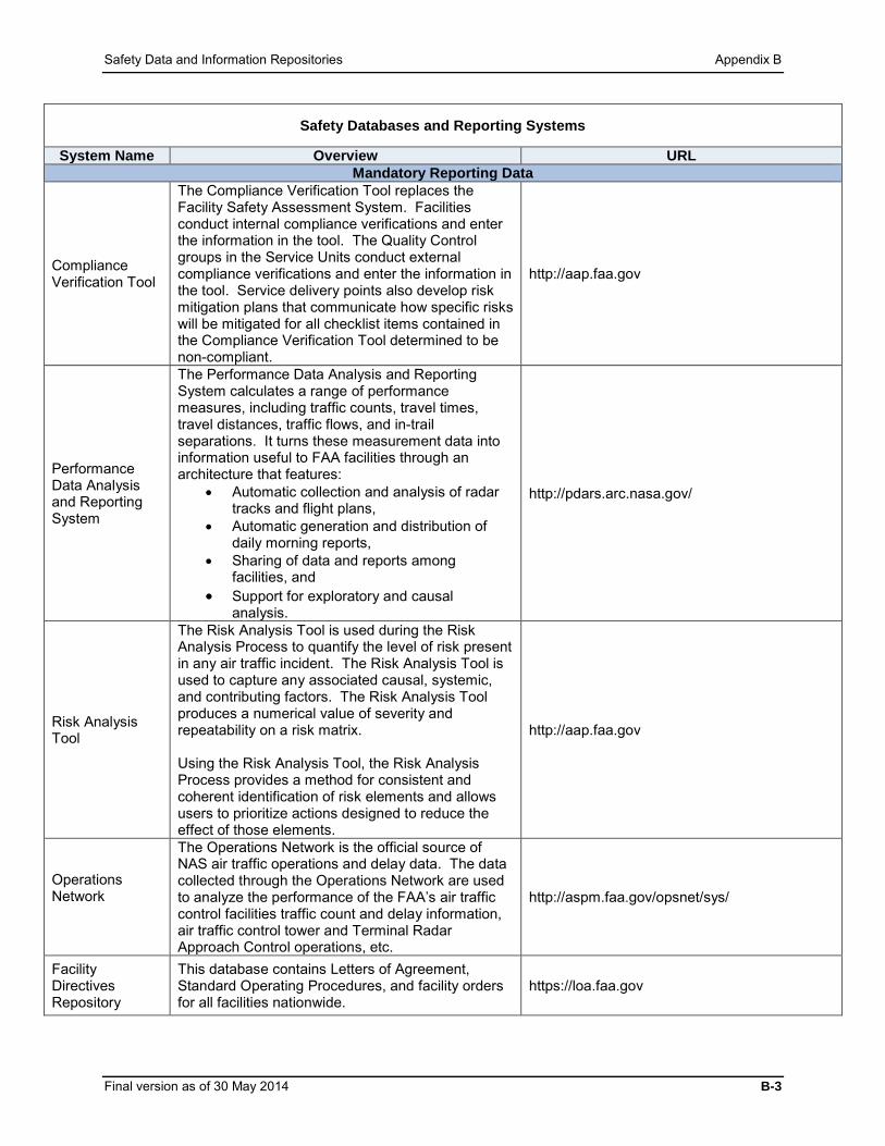
Safety Data and Information Repositories Appendix B
Safety Databases and Reporting Systems
System Name Overview URL Mandatory Reporting Data
Compliance Verification Tool
The Compliance Verification Tool replaces the Facility Safety Assessment System. Facilities conduct internal compliance verifications and enter the information in the tool. The Quality Control groups in the Service Units conduct external compliance verifications and enter the information in the tool. Service delivery points also develop risk mitigation plans that communicate how specific risks will be mitigated for all checklist items contained in the Compliance Verification Tool determined to be non-compliant.
http://aap.faa.gov
Performance Data Analysis and Reporting System
The Performance Data Analysis and Reporting System calculates a range of performance measures, including traffic counts, travel times, travel distances, traffic flows, and in-trail separations. It turns these measurement data into information useful to FAA facilities through an architecture that features:
• Automatic collection and analysis of radar tracks and flight plans,
• Automatic generation and distribution of daily morning reports,
• Sharing of data and reports among facilities, and
• Support for exploratory and causal analysis.
http://pdars.arc.nasa.gov/
Risk Analysis Tool
The Risk Analysis Tool is used during the Risk Analysis Process to quantify the level of risk present in any air traffic incident. The Risk Analysis Tool is used to capture any associated causal, systemic, and contributing factors. The Risk Analysis Tool produces a numerical value of severity and repeatability on a risk matrix. Using the Risk Analysis Tool, the Risk Analysis Process provides a method for consistent and coherent identification of risk elements and allows users to prioritize actions designed to reduce the effect of those elements.
http://aap.faa.gov
Operations Network
The Operations Network is the official source of NAS air traffic operations and delay data. The data collected through the Operations Network are used to analyze the performance of the FAA’s air traffic control facilities traffic count and delay information, air traffic control tower and Terminal Radar Approach Control operations, etc.
http://aspm.faa.gov/opsnet/sys/
Facility Directives Repository
This database contains Letters of Agreement, Standard Operating Procedures, and facility orders for all facilities nationwide.
https://loa.faa.gov
Final version as of 30 May 2014 B-3

Appendix B Safety Data and Information Repositories
Safety Databases and Reporting Systems
System Name Overview URL Voluntary Reporting
Aviation Safety Reporting System
The Aviation Safety Reporting System collects voluntarily submitted aviation safety incident/situation reports from pilots, controllers, and other personnel. It identifies system deficiencies, and issues messages to alert individuals in a position to correct the identified issues.
http://asrs.arc.nasa.gov
Aviation Safety Action Program
The Aviation Safety Action Program promotes voluntary reporting of safety issues and events that come to the attention of employees of certain certificate holders. It includes enforcement-related incentives to encourage employees to voluntarily report safety issues, even though the issues may involve an alleged violation of Title 14 of the Code of Federal Regulations.
http://www.faa.gov/about/initiatives/asap/
Air Traffic Safety Action Program
The Air Traffic Safety Action Program is a non-punitive, voluntary reporting program modeled after the Aviation Safety Action Program for employees delivering air traffic services. It allows for employees to submit safety concerns and deficiencies so issues can be resolved before a major error occurs. This voluntary reporting helps promote a strong safety culture within the ATO.
http://www.atsapsafety.com
TechNet
The TechNet website provides a means for expediently distributing NAS operational information within the FAA. It contains information such as NAS delay information by service (e.g., automation, surveillance, navigation, communication) and active equipment outages (i.e., full interruptions to service).
http://technet.faa.gov
Technical Operations Safety Action Program
The Technical Operations Safety Action Program is a voluntary, non-punitive safety reporting program for ATO Technical Operations Services personnel. Employees at the point of service have a unique understanding of safety and can better identify threats and risks to their particular operations. By studying the data gained from voluntary reports, safety issues can be more efficiently identified and mitigated.
http://www.t-sap.org
Reporting Tools
Lessons Learned Repositories
ATO manages and databases that will facilitate formal, structured information sharing within the ATO. Lessons Learned Repositories allow ATO employees to access and contribute lessons learned and best practices derived from successes and challenges.
B-4 Final version as of 30 May 2014

Safety Data and Information Repositories Appendix B
Table B.2: Data Types and Applicable Reporting Requirements
Data Types and Applicable Reporting Requirements Data Overview References
Mandatory Occurrence Reports
This order mandates that personnel collect and analyze data concerning air traffic incidents.
Order JO 7210.632, Air Traffic Organization Occurrence Reporting
Aircraft incident or accident
This order contains reporting requirements regarding safety issues, concerns, incidents, and accidents.
Order JO 8020.16, Air Traffic Organization Aircraft Accident and Incident Notification, Investigation, and Reporting
System outages This order mandates that outage reports be filed and contributes to daily system performance and incident reporting.
Order JO 6040.15, National Airspace Performance Reporting System
Significant system events
This order mandates that significant events be reported and contributes to daily system performance and incident reporting.
Order 6030.41, Notification of Facility and Service Interruptions and Other Significant Events
Unsatisfactory condition This order provides FAA employees with a means of informing management of unsatisfactory conditions.
Order 1800.6, Unsatisfactory Condition Report
Oceanic altitude and navigation errors
This order establishes procedures for processing reports and for collecting system data for analysis.
Order 7110.82, Reporting Oceanic Errors
Safety recommendations
This order establishes procedures for Aviation Safety Inspectors to report safety recommendations directly to the Office of Accident Investigation and Prevention.
Order 8020.16, Air Traffic Organization Aircraft Accident and Incident Notification, Investigation, and Reporting
Voluntary Safety Reports
This order defines the policy and procedures for ATO Voluntary Safety Reports. It identifies the responsibilities of individuals and organizations and the requirements, expectations, and policy under which the identified programs operate.
JO 7200.20, Voluntary Safety Reporting Programs (VSRP)
Final version as of 30 May 2014 B-5


SRM Documentation Requirements and Approval Checklists Appendix C
Appendix C. SRM Documentation Requirements and Approval Checklists
Safety Risk Management Decision Memorandum Template
Federal Aviation Administration
Memorandum Date: [Date]
To: [A designated management official from each affected Service Unit]
From: [Manager, Facility, or Organization]
Prepared By: [Name] Subject: Safety Risk Management Decision Memorandum (SRMDM) for [name of
proposed change/case file]
National Airspace System (NAS) Change: [In this section provide the following:
• Description of the NAS change
• Scope of the NAS change (e.g., facility-specific, multiple facilities)
• Reason for the proposed NAS change]
Rationale for Not Requiring Further Safety Risk Management (SRM) Analysis: [In this section provide the following:
• Reason why further analysis is not required for the proposed NAS change (i.e., why no hazards were identified with the NAS change and/or why the safety risk level is not affected)
• Supporting documentation used in the decision process that determined that the NAS change does not introduce a hazard, address an existing hazard in the NAS, or alter the current risk level of the affected operation or system.
• A statement that the reason for not performing further SRM analysis is in compliance with the Safety Management System (SMS) Manual and the supporting rationale.
• A statement that the proposed NAS change and the decision not to pursue a more thorough safety analysis have been coordinated with all affected organizations (e.g.,
Final version as of 30 May 2014 C-1

Appendix C SRM Documentation Requirements and Approval Checklists
“AJT and AJW have all reviewed and approved that the proposed NAS change does not introduce a hazard and/or change the current risk level of the NAS”).]
We, the undersigned, assure that the NAS change described above does not introduce a hazard, address an existing hazard, or change the risk level of the affected operation or system. Note: The signature blocks below represent the minimum signature requirement for an SRMDM that does not require the signature of the ATO Chief Safety Engineer. SRMDMs reviewed by the ATO Chief Safety Engineer require additional signature blocks.
Signature(s): Concurrence: ____________________ _______________________________ ________________ Signature Name and Organization Date ____________________ _______________________________ ________________ Signature Name and Organization Date
Approval:
____________________ _______________________________ ________________ Signature Name and Organization Date
File: Administrative WP: Draft SRM Decision Memo.doc AJI [TBD], [Name]:[TBD]:5-4811[Date]
C-2 Final version as of 30 May 2014

SRM Documentation Requirements and Approval Checklists Appendix C
SRMDM Review Checklist
Table C.1: SRMDM Review Checklist
# Requirement SMS Manual Reference Compliance
1 Is the document clearly titled?
Appendix C, SRMDM Template
Yes
No
2 Is the document appropriately dated?
Appendix C, SRMDM Template
Yes
No
3 Is the originator appropriately identified?
Appendix C, SRMDM Template
Yes
No
4
Did the designated management official(s) from the affected Service Unit(s) approve the document?
Section 5.3 Yes
No
5 Does the NAS change affect other FAA LOBs? Section 5.6.2
Yes
No
6
Did the affected organizations review and approve the safety assessment for accuracy and correctness?
Section 5.4.2 Section 5.6.1
Yes
No
N/A
7
Is this a change to a separation standard or periodicity of maintenance?
Section 5.6.3.1
Yes
No
8 Is the NAS change clearly described?
Section 4.2 Section 4.2.1
Yes
No
9 Were all stakeholders appropriately involved/ consulted?
Section 4.2 Yes
No
10 Was the correct level of safety analysis appropriately identified?
Section 4.2.3 Yes
No
11 Is there clear justification/rationale for the SRM decision?
Section 4.2.3.1
Yes
No
Final version as of 30 May 2014 C-3

Appendix C SRM Documentation Requirements and Approval Checklists
Safety Risk Management Document Sections and Criteria
Cover Page Include the SRMD title, version number, and date. Include a subtitle that makes clear the type of analysis.
• Creating an SRMD Version Number: An initial draft version that is ready for approval should be numbered “1.0” before going through the approval process. Editorial and administrative updates to the SRMD that do not constitute a change to the safety analysis are considered minor revisions. They begin with “0.1” and increase incrementally by .1. Major revisions are changes to the SRMD that represent a change to the safety analysis such that hazards, safety requirements, and safety performance targets are altered. Such changes would require new risk acceptance and approval signatures. The initial final draft of the SRMD is also considered a major revision. These documents are represented by whole numbers (e.g., 1, 2, 3).
SRMD Change Page Include a table listing changes made to the different versions of the SRMD, including the corresponding date and version number. Executive Summary The following constitutes minima criteria for an SRMD executive summary:
Section Description
Title A clear and concise name of the SRMD that describes the proposed NAS change.
Originator Information (i.e., change proponent) Originator’s name, organization, and contact information.
SRMD Identification and Configuration Management
SRMD submission date, SRMD version number, and SRMD number.
Summary of the NAS Change A general description of the proposed NAS change/procedure and the process/method that was used to move through the SRM process. Provide a statement reflecting the impact of the issue or system. The SRM panel should identify the tool used to describe the system and/or the NAS change (e.g., 5M Model). Refer to the SMS Manual for more information. When applicable, briefly summarize previous associated NAS changes and make clear the relationship between the current NAS change described and assessed in this SRMD and others already implemented.
Risk Assessment A table describing the hazards and risks identified (initial and predicted residual risk).
C-4 Final version as of 30 May 2014
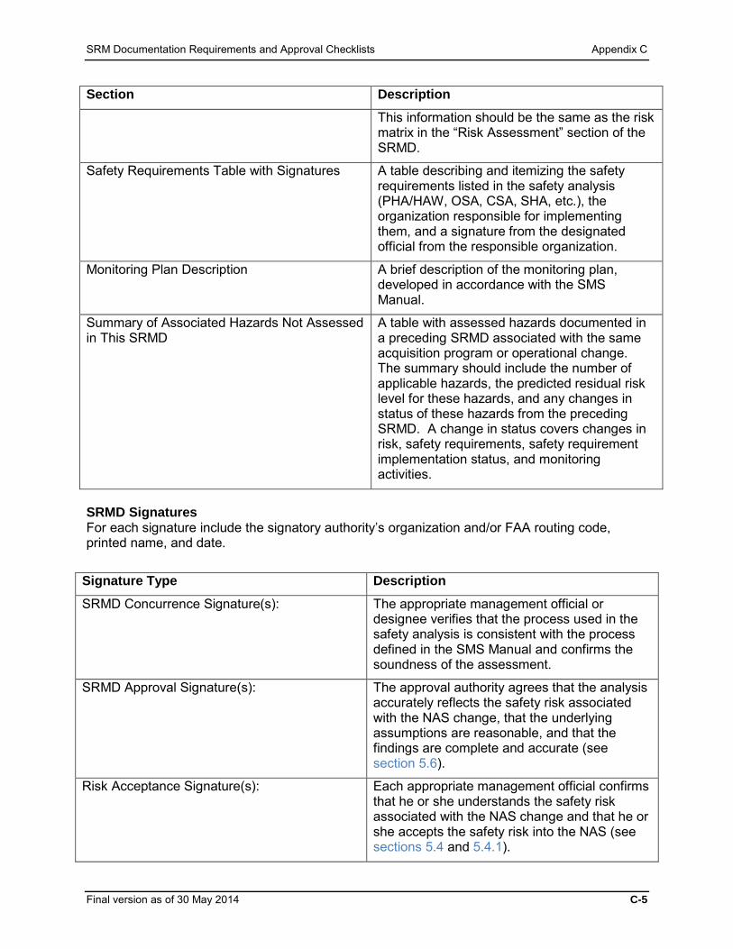
SRM Documentation Requirements and Approval Checklists Appendix C
Section Description
This information should be the same as the risk matrix in the “Risk Assessment” section of the SRMD.
Safety Requirements Table with Signatures A table describing and itemizing the safety requirements listed in the safety analysis (PHA/HAW, OSA, CSA, SHA, etc.), the organization responsible for implementing them, and a signature from the designated official from the responsible organization.
Monitoring Plan Description A brief description of the monitoring plan, developed in accordance with the SMS Manual.
Summary of Associated Hazards Not Assessed in This SRMD
A table with assessed hazards documented in a preceding SRMD associated with the same acquisition program or operational change. The summary should include the number of applicable hazards, the predicted residual risk level for these hazards, and any changes in status of these hazards from the preceding SRMD. A change in status covers changes in risk, safety requirements, safety requirement implementation status, and monitoring activities.
SRMD Signatures For each signature include the signatory authority’s organization and/or FAA routing code, printed name, and date.
Signature Type Description
SRMD Concurrence Signature(s): The appropriate management official or designee verifies that the process used in the safety analysis is consistent with the process defined in the SMS Manual and confirms the soundness of the assessment.
SRMD Approval Signature(s): The approval authority agrees that the analysis accurately reflects the safety risk associated with the NAS change, that the underlying assumptions are reasonable, and that the findings are complete and accurate (see section 5.6).
Risk Acceptance Signature(s): Each appropriate management official confirms that he or she understands the safety risk associated with the NAS change and that he or she accepts the safety risk into the NAS (see sections 5.4 and 5.4.1).
Final version as of 30 May 2014 C-5

Appendix C SRM Documentation Requirements and Approval Checklists
Proposal Rejection Signature (when applicable):
When a proposed NAS change is considered unsafe for implementation, this should be recorded in the SRMD with accompanying rationale and the appropriate signatures. Proposal rejection should come from the risk acceptor or approval authority.
Section 1—Current System Provide a detailed description of the system/procedure, its operational environment, the people involved/affected by the NAS change/procedure, and the equipment required to accommodate the NAS change. Use the 5M Model as discussed in chapter 3 for assistance.
1. Provide an explanation of what triggered the undertaking of the safety analysis.
2. Describe the current hardware or software system or existing procedures and the corresponding (operational) system states.
3. If the proposal entails a procedural change, describe the current procedure and its
operational environment. If the current system or procedure is unique and has challenges associated with its unique situation, be sure to point these out.
4. Address any planned future configuration, system, or procedural changes that might
affect the proposed change/procedure. Section 2—Change Proposed Include a detailed description of the proposed NAS change/procedure, identifying which safety parameters are involved.
1. Describe the proposed NAS change/procedure and identify which critical safety parameters are involved (e.g., prohibited/restricted airspace, noise abatement area, operational limitation).
2. Discuss the types of verifications that will be performed throughout the development process to review whether the finalized proposed NAS change will be safe, operational, and effective once implemented. Evaluation can consist of simulator modeling, live testing, or a combination thereof.
3. Provide a depiction of the proposed NAS change/procedure.
4. Address the monitoring methods that will be used to verify system performance after implementation.
5. Define and document all assumptions made to make the evaluation of the NAS change more manageable, or to better scope the analysis.
6. Provide a reference to any related or preceding safety analyses.
7. Discuss preceding SRM efforts and associated hazards and risks that have an effect on the current proposed NAS change (acquisition program or operational change). Provide a table that includes the initial risk level, predicted residual risk level, safety requirements (if any), safety requirement implementation status, monitoring activities, and their statuses.
C-6 Final version as of 30 May 2014

SRM Documentation Requirements and Approval Checklists Appendix C
Section 3—Safety Risk Management Panel
1. List the SRM panel members, including their title, specialty, and years of experience, and indicate whether they attended/participated in the SRM panel. (It is not necessary to indicate attendance for each meeting; document if a stakeholder was invited but did not participate.)
2. Describe the panel meeting schedule, responsibilities, and milestones achieved. Explain how the SRM panel worked through the SRM process.
3. If there is an existing process that was successfully used to develop and implement earlier systems, procedures, or NAS changes, then provide insight into how this process relates to the SRM and, if applicable, how this process was modified to meet all SRM requirements.
Section 4—Risk Assessment
1. Specify and discuss the tool(s) and technique(s) used to identify hazards.
2. Document the identified hazards, as well as their causes, the corresponding system states considered, and credible outcomes. Do not identify hazards that are not relevant to the proposed NAS change.
3. Describe the process used to analyze the risks associated with the identified hazards, referencing the severity and likelihood definitions of the current version of the SMS Manual.
4. Specify what types of data were used to determine the likelihood of the effect’s occurrence (e.g., quantitative or qualitative), as well as the source(s) of the data. If qualitative estimations are used, provide a rationale for the estimate in enough detail that the reviewer can ensure that the analysis was thorough, fair, and objective.
5. Identify all hazard effects and risk levels. Hazards may have effects that result in multiple risk levels. Indicate the risk of the hazard based on the effect with the highest risk level.
Section 5—Risk Treatment and Monitoring
1. Document the safety requirements, associated safety performance targets, and the predicted residual risk level. A well-developed monitoring plan should help:
o Verify the safety performance of all system safety requirements / existing controls,
o Verify the implementation of existing controls and/or safety requirements, and
o Identify any unintended safety risk consequences.
2. Explain the steps to take to reduce the estimated likelihood of the hazard or credible effect(s) from occurring, thus reducing the initial risk. In identifying safety requirements, specify the organization responsible to implement each safety requirement.
Note: In most cases, safety requirements must be validated before seeking SRMD approval. Refer to section 3.6.1.1 for further discussion of validation and verification of safety requirements.
3. All proposed safety requirements, whether for acceptable or unacceptable risk, must be included in the PHA/HAW. The SRM panel may identify optional risk mitigations that
Final version as of 30 May 2014 C-7

Appendix C SRM Documentation Requirements and Approval Checklists
would not be considered safety requirements. Such mitigations are documented in the “Risk Treatment and Monitoring” section of the SRMD.
Note: If the risk cannot be reduced to an acceptable level after attempting all possible mitigation strategies, either revise the original objectives or abandon the proposed NAS change. This conclusion must be included in the SRMD. If a NAS change was implemented without safety requirements and the predicted residual risk was not met, the SRMD must be revisited, which may require the development of safety requirements (see sections 3.7.2 and 5.3). Ensure that the authority responsible for the implementation of the safety requirement(s) is aware of the requirement and was/is involved in the safety analysis.
4. Using the risk matrix, illustrate the initial and predicted residual risk(s) associated with the identified hazards. Hazards that have multiple effects may have multiple levels of risk associated with them.
5. Create a monitoring plan that outlines the methodology to track and monitor the hazard(s) to determine whether the predicted residual risk and safety performance targets are met. If an alternate method is used in lieu of a safety performance target, clearly document and explain how it will be used to verify the predicted residual risk in the SRMD. Refer to section 3.6.5 for monitoring plan requirements.
Appendices Use appendices to include the following:
• The complete PHA/HAW at minimum, and any additional safety analyses • Relevant references, • Terms and definitions, and • Comments and concerns from dissenting SRM panel members.
C-8 Final version as of 30 May 2014

SRM Documentation Requirements and Approval Checklists Appendix C
SRMD Review Checklist
Table C.2: SRMD Review Checklist
# Requirement SMS Manual Reference Compliant?
1 There are five major sections that must be included in the SRMD. Are all five sections included?
Appendix C, SRMD Sections and Criteria
Yes
No
2 Is the document clearly titled and dated?
Appendix C, SRMD Sections and Criteria
Yes
No
3 Is the originator appropriately identified?
Appendix C, SRMD Sections and Criteria
Yes
No
4 Did the appropriate individuals review the document? Section 4.3.6.5
Yes
No
5 Did the appropriate individuals accept the risk(s) outlined in the document?
Section 5.4 Yes
No
6 Did the NAS change cross or affect other FAA LOBs?
Section 3.2.1.2 Section 3.3.6 Section 5.4.2
Yes
No
6a If so, were the requirements of Order 8040.4 met?
Section 3.2.1.2 Section 3.3.6 Section 5.4.2
Yes
No
N/A
7
Does the executive summary include justification of the proposed NAS change, a summary of the hazards, the corresponding initial and predicted residual risks, and the safety requirements and necessary signatures?
Appendix C, SRMD Sections and Criteria
Yes
No
8 Does the SRMD sufficiently describe the system in which the NAS change will be made?
Section 3.2.2 Section 3.2.3
Yes
No
Final version as of 30 May 2014 C-9

Appendix C SRM Documentation Requirements and Approval Checklists
# Requirement SMS Manual Reference Compliant?
9
Does the SRMD provide a description of the system/ procedure, its operational environment, the organizations involved / affected by the NAS change/procedure, the equipment required to accommodate the NAS change/procedure, etc.?
Section 3.2.2 Yes
No
10 Does the document provide a rationale for the NAS change/procedure?
Section 3.2.2 Yes
No
11 Was the proposed NAS change described in detail? Section 3.2.2
Yes
No
12 Is the potential impact of the proposed NAS change appropriately bounded?
Section 3.2.1 Section 3.2.3
Yes
No
13 Existing hazards only:
Does the “Proposed Change” section describe how the existing hazard was discovered?
Section 3.3.3
Yes
No
N/A
14 Are assumptions clearly defined and documented? Section 4.3.3
Yes
No
15
This panel needs to include representatives of the various organizations concerned with and impacted by the specification, development, and use of the system. Did the panel of SMEs include the required representatives?
Section 4.3.4 Yes
No
16 Are the identified hazards described in detail? Section 3.3
Yes
No
16a Has a description of the method for identifying hazards been included? Section 3.3.5.3
Yes
No
16b Do the causes and system states for the hazard adequately reflect conditions that would reduce system operability or service?
Section 3.3.2 Yes
No
16c Is the system state clear? Section 3.3.2 Yes
No
C-10 Final version as of 30 May 2014

SRM Documentation Requirements and Approval Checklists Appendix C
# Requirement SMS Manual Reference Compliant?
17 Do the controls map to causes such that the cause to control relationship is understood?
Section 3.4.1 Yes
No
18 Are appropriate existing controls identified with supporting justification included?
Section 3.4.1 Yes
No
19 Were the severities of the identified hazards determined? Section 3.4.4
Yes
No
19a Was supporting rationale provided? Section 3.4.4 Yes
No
20 Were the likelihoods of outcomes of the identified hazards determined? Section 3.4.5
Yes
No
20a Was supporting rationale provided? Section 3.4.5.1 Yes
No
21
If likelihood and severity levels are determined:
Quantitatively: Are data present to validate and verify results?
Qualitatively: Are the conclusions sufficiently explained?
Section 3.4.5.3 Section 3.4.5.4
Yes
No
21a If qualitative reasoning was used, could quantitative data have been used in lieu of it?
Section 3.4.5.3 Section 3.4.5.4
Yes
No
N/A
21b Severity is determined by the credible potential outcome. Have credible effects been considered?
Section 3.4.2 Yes
No
21c Were historical data (frequency) used to calculate likelihood? Section 3.4.5.2
Yes
No
N/A
22 Are initial risks and predicted residual risks identified in the PHA/HAW?
Section 3.3.5.2 Section 3.4.3.1 Section 3.6.3
Yes
No
23 Were the risks associated with the identified hazards appropriately categorized as high, medium, or low?
Section 3.5.1 Section 3.5.2
Yes
No
Final version as of 30 May 2014 C-11
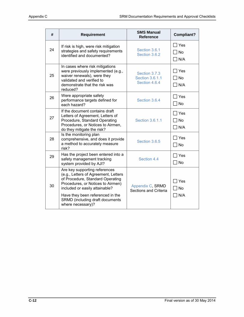
Appendix C SRM Documentation Requirements and Approval Checklists
# Requirement SMS Manual Reference Compliant?
24 If risk is high, were risk mitigation strategies and safety requirements identified and documented?
Section 3.6.1 Section 3.6.2
Yes
No
N/A
25
In cases where risk mitigations were previously implemented (e.g., waiver renewals), were they validated and verified to demonstrate that the risk was reduced?
Section 3.7.3 Section 3.6.1.1 Section 4.6.4
Yes
No
N/A
26 Were appropriate safety performance targets defined for each hazard?
Section 3.6.4 Yes
No
27
If the document contains draft Letters of Agreement, Letters of Procedure, Standard Operating Procedures, or Notices to Airmen, do they mitigate the risk?
Section 3.6.1.1
Yes
No
N/A
28 Is the monitoring plan comprehensive, and does it provide a method to accurately measure risk?
Section 3.6.5 Yes
No
29 Has the project been entered into a safety management tracking system provided by AJI?
Section 4.4 Yes
No
30
Are key supporting references (e.g., Letters of Agreement, Letters of Procedure, Standard Operating Procedures, or Notices to Airmen) included or easily attainable?
Have they been referenced in the SRMD (including draft documents where necessary)?
Appendix C, SRMD Sections and Criteria
Yes
No
N/A
C-12 Final version as of 30 May 2014

FAA Documents Related to SMS Requirements Appendix D
Appendix D. FAA Documents Related to SMS Requirements The following documents (orders, directives, regulations, handbooks, and manuals) address National Airspace System (NAS) safety management and are related to the processes described in this Safety Management System (SMS) Manual. Note that this list is not all-inclusive and only represents a small portion of Federal Aviation Administration (FAA) documents that pertain to safety management. Some documents listed may have been updated since the publication of this SMS Manual. Refer to the following websites for current editions: For advisory circulars: http://rgl.faa.gov For orders and notices: http://www.faa.gov/regulations_policies/orders_notices/ For Federal aviation regulations: http://www.faa.gov/regulations_policies/faa_regulations/ General: a. Advisory Circular 00-46, Aviation Safety Reporting Program b. DOT/FAA/AR-03/69, FAA Human Factors Acquisition Job Aid c. HF-STD-001, Human Factors Design Standard (HFDS) d. Order 1220.2, FAA Procedures for Handling National Transportation Safety Board
Recommendations e. Order 1800.6, Unsatisfactory Condition Report f. Order 1100.161, Air Traffic Safety Oversight g. Order 8000.73, Aviation Safety Hotline Program h. Order 8000.86, Air Traffic Safety Oversight Compliance Process i. Order 9550.8, Human Factors Policy
Airports: a. Order 5010.4, Airport Safety Data Program b. Order 5200.11, FAA Airports (ARP) Safety Management System c. Title 14 of the Code of Federal Regulations, Part 77, Safe, Efficient Use, and Preservation of
the Navigable Airspace d. Title 14 of the Code of Federal Regulations, Part 139, Certification of Airports e. Title 14 of the Code of Federal Regulations, Part 157, Notice of Construction, Alteration,
Activation, and Deactivation of Airports
Air Traffic Control: a. Advisory Circular 120-66, Aviation Safety Action Program (ASAP) b. Order 1100.2, Organization – FAA Headquarters c. Order 1800.14, Airway Facilities Evaluation Program d. Order JO 3120.4, Air Traffic Technical Training e. Order JO 6040.15, National Airspace Performance Reporting System f. Order 6050.19, Radio Spectrum Planning g. Order 6050.22, Radio Frequency Interference Investigation and Reporting h. Order 6050.32, Spectrum Management Regulations and Procedures Manual i. Order 6480.4, Airport Traffic Control Tower Siting Process j. Order 7050.1, Runway Safety Program k. Order JO 7110.10, Flight Services l. Order JO 7110.65, Air Traffic Control m. Order 7110.82, Reporting Oceanic Errors n. Order 7110.112, Simultaneous ILS/MLS Blunder Data Collection o. Order JO 7200.20, Voluntary Safety Reporting Programs (VSRP)
Final version as of 30 May 2014 D-1

Appendix D FAA Documents Related to SMS Requirements
p. Order JO 7210.3, Facility Operation and Administration q. Order JO 7210.632, Air Traffic Organization Occurrence Reporting r. Order JO 7210.633, Air Traffic Organization Quality Assurance Program (QAP) s. Order JO 7210.634, Air Traffic Organization (ATO) Quality Control t. Order 7220.1, Certification and Rating Procedures for Department of Defense (DoD)
Personnel u. Order JO 7400.2, Procedures for Handling Airspace Matters v. Order 7450.1, Special Use Airspace Management System w. Order JO 7610.4, Special Operations x. Order JO 7900.2, Reporting of Electronic Navigation Aids, Communication Facilities, and
Aviation Weather Systems Data to the National Flight Data Center y. Order 7910.3, Position Display Map Program z. Order JO 7930.2, Notices to Airmen (NOTAM) aa. Order JO 8020.16, Air Traffic Organization Aircraft Accident and Incident Notification,
Investigation, and Reporting
Facilities and Equipment: a. Order JO 1320.58, Instructions for Writing Notices, Maintenance Technical Handbooks, and
System Support Directives b. Order 1800.66, Configuration Management Policy c. Order JO 1900.47, Air Traffic Control Operational Contingency Plans d. Order 3000.57, Air Traffic Organization Technical Operations Training and Personnel
Certification e. Order 3900.19, FAA Occupational Safety and Health Program f. Order 4140.1, Integrated Materiel Management Program g. Order 4630.5, Quality and Reliability Assurance of General Operating Materiel Managed by
the FAA Logistics Center h. Order 6000.15, General Maintenance Handbook for National Airspace System (NAS)
Facilities i. Order 6000.30, National Airspace System Maintenance Policy j. Order 6000.46, Remote Monitoring and Logging System (RMLS) Software Operations and
Management k. Order JO 6000.50, National Airspace System (NAS) Integrated Risk Management l. Order JO 6000.53, Remote Maintenance Monitoring Interface Development and
Implementation m. Order 6000.54, Airway Facilities Hazard Communication Program n. Order JO 6030.31, National Airspace System Infrastructure Failure Response o. Order JO 6030.41, Notification of Facility and Service Interruptions and Other Significant
Events p. Order 6032.1, National Airspace System Modification Program q. Order JO 6040.6, National Airspace System Technical Evaluation Program r. Order JO 6300.13, Radar Systems Optimization and Flight Inspection Handbook s. Order 7900.4, Reporting of Military-Certified Air Navigation Facilities to the National Flight
Data Center (NFDC) (RIS: AT 7900-20) t. Order 7920.1, Content Criteria for Airman’s Information Publications Originating in the
National Flight Data Center
Flight Procedure / Flight Inspection: a. Order 8200.1, United States Standard Flight Inspection Manual b. Order JV-3 3410.2, Aeronautical Navigation Products Career Progression and Certification
Program for Aeronautical Information Specialists
D-2 Final version as of 30 May 2014

FAA Documents Related to SMS Requirements Appendix D
c. Order 8240.36, Flight Inspection Report Processing System (FIRPS) d. Order 8260.15, United States Army Terminal Instrument Procedures Service e. Order 8260.16, Airport Obstruction Surveys f. Order 8260.19, Flight Procedures and Airspace g. Order 8260.23, Calculation of Radio Altimeter Height h. Order 8260.26, Establishing and Scheduling Civil Public-Use Standard Instrument
Procedure Effective Dates i. Order 8260.3, United States Standard for Terminal Instrument Procedures (TERPS) j. Order 8260.31, Foreign Terminal Instrument Procedures (FTIP) k. Order 8260.32, U.S. Air Force Terminal Instrument Procedures Service l. Order VN 8260.4, ILS Obstacle Risk Analysis m. Order 8260.42, United States Standard for Helicopter Area Navigation (RNAV) n. Order 8260.43, Flight Procedures Management Program o. Order 8260.46, Departure Procedure (DP) Program p. Order 8260.58, United States Standard for Performance Based Navigation (PBN)
Instrument Procedure Design
New Systems: a. Federal Aviation Administration Acquisition Management System b. System Engineering Manual (SEM)
Safety Management Systems: a. Advisory Circular 25.1309, System Design and Analysis b. AOV SOC 07-02, AOV Concurrence/Approval at Various Phases of Safety Risk
Management Documentation and Mitigations for Initial High-Risk Hazards c. AOV SOC 07-05, Guidance on Safety Risk Modeling and Simulation of Hazards and
Mitigations d. Order JO 1000.37, Air Traffic Organization Safety Management System e. Order JO 1000.38, Technical Operations Services Safety Management System Internal
Safety Assurance Program f. Order JO 1030.1, Air Traffic Organization Safety Guidance g. Order 1100.161, Air Traffic Safety Oversight h. Order JO 7010.1, Air Traffic Organization Safety Evaluations and Audits i. Order 8000.365, Safety Oversight Circulars (SOC) j. Order 8000.369, Safety Management System k. Order 8040.4, Safety Risk Management Policy
Final version as of 30 May 2014 D-3

Definitions Appendix E
Appendix E. Definitions
Note: In cases where both FAA and ATO definitions are provided for the same term, the ATO definition is provided as an expansion of the FAA definition to facilitate understanding when communicating within the ATO. In those cases where terms and resultant effects are communicated outside the ATO, the FAA definition will be the standard of reference.
Acceptable Level of Safety Risk. Medium or low safety risk.
Accident. An unplanned event or series of events that results in death, injury, or damage to, or loss of, equipment or property.
Active Failure. An error of omission or commission that is made in the course of a particular operation. An active failure can also be a known problem or a known mechanical deficiency or fault.
Acquisition Management System (AMS). FAA policy dealing with any aspect of lifecycle acquisition management and related disciplines. The AMS also serves as the FAA’s Capital Planning and Investment Control process.
AOV Acceptance. The process whereby the regulating organization has delegated the authority to the service provider to make changes within the confines of approved standards and only requires the service provider to notify the regulator of those changes within 30 days. Changes made by the service provider in accordance with their delegated authority can be made without prior approval by the regulator.
AOV Approval. The formal act of approving a NAS change submitted by a requesting organization. This action is required prior to the proposed NAS change being implemented.
Assessment. A process of measuring or judging the value or level of something.
Assumptions. Characteristics or requirements of a system or system state that are neither validated nor verified, but are taken as such.
Audit. A review of an organization’s safety programs or initiatives to verify completion of tasks and determine an organization’s compliance with FAA directives and procedures.
Baseline. The written processes, procedures, specifications, and other conditions of the system that were accepted as the starting point for oversight of safety in the NAS on March 14, 2005. ATO must maintain the NAS at a safety level that is at least equal to that state, in compliance with current policies, processes, and procedures that are documented in its orders, handbooks, and manuals. (Note: “Acceptance of the baseline did not imply or state that the NAS was or was not inherently safe as configured on that date, nor did it imply that the NAS had no existing high risks,” AOV SOC 07-01, Acceptance of the Air Traffic Organization (ATO) Baseline.
Bounding. A process of limiting the analysis of the NAS change or system to only the elements that affect or interact with each other to accomplish the central function.
Cause. The origin of a hazard.
Final version as of 30 May 2014 E-1

Appendix E Definitions
Change Proponent. The individual, program office, facility, or organization proposing a NAS change.
Common Cause Failure. A failure that occurs when a single fault results in the corresponding failure of multiple system components or functions.
Compliance Audit. An audit that evaluates or assesses conformance to established criteria, processes, and work practices. The objective of a compliance audit is to determine if employees and processes have followed established policies and procedures.
Continuous Loop. SRM processes are repeated until the safety risk associated with each hazard is acceptable and has met its predicted residual risk.
Concurrence. Verification that the process used in the safety analysis is consistent with the process defined in the document and in the SMS Manual (or other industry standard alternatives).
Configuration Management. A process for establishing and maintaining consistency of a product’s performance, functional and physical attributes with its requirements, design, and operational information throughout its life.
Confirmation. The act of using a written response from a third party to confirm the integrity of a specific item or assertion.
Control.
• FAA Definition. Safety Risk Control: A means to reduce or eliminate the effects of hazards.
• ATO Definition. Anything that is validated or verified to mitigate or manage the risk of a hazard’s effect or occurrence. (See “Mitigation.”)
Credible. It is reasonable to expect that the assumed combination of conditions that define the system state will occur within the operational lifetime of a typical ATC system.
Critical NAS System. A system that provides functions or services that, if lost, would prevent users of the NAS from exercising safe separation and control over aircraft.
Current Risk.
• FAA Definition. The predicted severity and likelihood at the current time.
• ATO Definition. The assessed severity and frequency of a hazard’s effects in the present state.
Development Assurance. All the planned and systematic actions used to substantiate, at an adequate level of confidence, that errors in requirements, design, and implementation have been identified and corrected such that the system satisfies the applicable approval or certification basis.
E-2 Final version as of 30 May 2014

Definitions Appendix E
Effect. The real or credible harmful outcome that has occurred or can be expected if the hazard occurs in the defined system state.
Equipment. A complete assembly—operating either independently or within a system/sub-system—that performs a specific function.
Error-Tolerant System. A system that is designed and implemented in such a way that, to the maximum extent possible, errors and equipment failures do not result in an incident or accident. An error-tolerant design is the human equivalent of a fault-tolerant design.
Existing Control. A mitigation already in place that prevents or reduces the hazard’s likelihood or mitigates its effects. A control can only be considered existing if it has been validated and verified with objective evidence.
Facility. Generally, any installation of equipment designated to aid in the navigation, communication, or control of air traffic. Specifically, the term denotes the total electronic equipment, power generation, or distribution systems and any structure used to house, support, and/or protect these equipment and systems. A facility may include a number of systems, sub-systems, and equipment.
Fail Safe. A system designed such that if it fails, it fails in a way that will cause no harm to other devices or present a danger to personnel.
Fail Operational. A system designed such that if it sustains a fault, it still provides a subset of its specified behavior.
Fault Tolerance. The ability of a system to respond without interruption or loss of capabilities in the event of an unexpected hardware or software failure.
Frequency. An expression of how often a given effect occurs.
Hazard.
• FAA Definition. A condition that could foreseeably cause or contribute to an accident.
• ATO Definition. Any real or potential condition that can cause injury, illness, or death to people; damage to or loss of a system, equipment, or property; or damage to the environment. A hazard is a prerequisite to an accident or incident.
Hazard Analysis Worksheet (HAW). A tool used to provide an initial overview of the hazards present in the overall flow of the operation. The HAW is the non-acquisitions equivalent of the PHA.
Hazard Identification. The determination of the hazard scenarios and associated consequences (undesired events) as a consequence of introducing a new system into the NAS. This provides an intermediate product that expresses the hazards that will be used during risk analysis.
High-Risk Hazard. A hazard with an unacceptable level of safety risk; the NAS change cannot be implemented unless the hazard’s associated risk is mitigated and reduced to medium or low.
Final version as of 30 May 2014 E-3
Appendix E Definitions
Human-Centered. The structured process during concept and requirement definition, design, development, and implementation that identifies the user as the focal point of the effort for which procedures, equipment, facilities, and other components serve to support human capabilities and compensate for human limitations; sometimes also called “user-centered.”
Human Factors. A multidisciplinary effort to generate and compile information about human capabilities and limitations and apply that information to equipment, systems, facilities, procedures, jobs, environments, training, staffing, and personnel management for safe, comfortable, and effective human performance. (See Order 9550.8, Human Factors Policy.)
Incident. An occurrence other than an accident that affects or could affect the safety of operations.
Initial Risk.
• FAA Definition. The predicted severity and likelihood of a hazard’s effect or outcomes when it is first identified and assessed; includes the effects of preexisting risk controls in the current environment.
• ATO Definition. The composite of the severity and likelihood of a hazard, considering only existing controls and documented assumptions for a given system state. It describes the risk before any of the proposed mitigations are implemented.
Inquiry. The technique of asking questions and recording responses.
Inspection. The act of critically examining documents to determine the content and quality of a transaction, such as inspecting leases, contracts, meeting minutes, requirements, and organization policy.
Latent Failure. An error or failure whose adverse consequences may lie dormant within a system for a long time, becoming evident when combined with other factors.
Likelihood. The estimated probability or frequency, in quantitative or qualitative terms, of a hazard’s effect or outcome.
Maintenance. Any repair, adaptation, upgrade, or modification of NAS equipment or facilities. This includes preventive maintenance.
Mitigation. A means to reduce the risk of a hazard.
Mitigation Strategy. Actions designed to reduce or manage the risk associated with a NAS change or operation.
National Airspace System (NAS). A complex system that is composed of airspace, airports, aircraft, pilots, air navigation facilities, and Air Traffic Control (ATC) facilities; communication, navigation, and surveillance services and supporting technologies and systems; operating rules, regulations, policies, and procedures; and people who implement, sustain, or operate the system components.
NAS Change. A modification to any element of the NAS that pertains to, or could affect the provision of air traffic management, communication, navigation, or surveillance services.
E-4 Final version as of 30 May 2014

Definitions Appendix E
Objective Evidence. Documented proof; the evidence must not be circumstantial and must be obtained through observation, measurement, test, or other means.
Observation. The process of witnessing an organization’s process. It differs from a physical examination in that the auditor only observes the process; no physical evidence is obtained.
Operational Assessments. An assessment to address the effectiveness and efficiency of the organization. The objective of an operational assessment is to determine the organization’s ability to achieve its goals and accomplish its mission.
Oversight. Regulatory supervision to validate the development of a defined system and verify compliance to a pre-defined set of standards.
Physical Examination. The act of gathering physical evidence. It is a substantive test involving the counting, inspecting, gathering, and inventorying of physical and tangible assets, such as cash, plants, equipment, and parameters.
Preconditions. The system states or variables that must exist for a hazard or an accident to occur in an error-tolerant system.
Predicted Residual Risk. The risk that is estimated to exist after the safety requirements are implemented, or after all avenues of risk mitigation have been explored.
Preliminary Hazard Analysis (PHA). An acquisitions tool used to provide an initial overview of the hazards present in the overall flow of the operation. The PHA provides a hazard assessment that is broad, but usually not deep.
Preliminary Hazard List. A hazard identification tool used to list all potential hazards in the overall operation. Development of a Preliminary Hazard List typically begins with a brainstorming session among the individuals performing the safety analysis.
Process. A set of interrelated or interacting activities that transforms inputs into outputs.
Program Assessment. A Safety Assessments review of an organization’s safety programs or initiatives. Programs and initiatives include, but are not limited to, Service Area Quality Assurance, Air Traffic Facility Quality Control, Runway Incursion Prevention Plans, Equipment Availability Programs, and Contractor Quality Assurance programs for FAA contract towers.
Qualitative Data. Subjective data that is expressed as a measure of quality; nominal data.
Quality Assurance. A program for the systematic monitoring and evaluation of the various aspects of a project, service, or facility to ensure that standards of quality are being met. It is a process to assess and review the processes and systems that are used to provide outputs (whether services or products) and to identify risks and trends that can be used to improve these systems and processes.
Quality Control. A process that assesses the output (whether a product or service) of a particular process or function and identifies any deficiencies or problems that need to be addressed.
Final version as of 30 May 2014 E-5

Appendix E Definitions
Quantitative Data. Objective data expressed as a quantity, number, or amount, allowing for a more rational analysis and substantiation of findings.
Recording. The process of documenting the identified hazards and the associated safety analysis information.
Redundancy. A design attribute in a system that ensures duplication or repetition of elements to provide alternative functional channels in case of failure. Redundancy allows the service to be provided by more than one path to maximize the availability of the service.
Requirement. An essential attribute or characteristic of a system. It is a condition or capability that must be met or passed by a system to satisfy a contract, standard, specification, or other formally imposed document or need.
Residual Risk.
• FAA Definition. The remaining predicted severity and likelihood that exist after all selected risk control techniques have been implemented.
• ATO Definition. The level of risk that has been verified by completing a thorough monitoring plan with achieved measurable safety performance target(s). Residual risk is the assessed severity of a hazard’s effects and the frequency of the effect’s occurrence.
Risk. The composite of predicted severity and likelihood of the potential effect of a hazard.
Risk Acceptance. The confirmation by the appropriate management official that he or she understands the safety risk associated with the NAS change and that he or she accepts that safety risk into the NAS. Risk acceptance requires that signatures have been obtained for the safety requirements identified in the SRMD and that a comprehensive monitoring plan has been developed and will be followed to verify the predicted residual risk.
Risk Analysis Event. A loss of standard separation between two aircraft in a radar environment that results in less that 66 percent of the applicable separation minima maintained.
Risk Assumption Strategy. A risk management strategy used to accept the risk.
Risk Avoidance Strategy. A risk management strategy used to avert the potential occurrence and/or consequence of a hazard by either selecting a different approach or not implementing a specific proposal.
Risk Control Strategy. A risk management strategy used to develop options and take actions to lower the risk.
Risk Mitigation. Refer to “Mitigation.”
Risk Transfer Strategy. A risk management strategy used to shift the ownership of a risk to another party.
Safety. The state in which the risk of harm to persons or property damage is acceptable.
E-6 Final version as of 30 May 2014

Definitions Appendix E
Safety Assurance. Processes within the SMS that function systematically to measure safety performance and determine whether an organization meets or exceeds its safety objectives through the collection, analysis, and assessment of information.
Safety Culture. The way safety is perceived and valued in an organization. It represents the priority given to safety at all levels in the organization and reflects the real commitment to safety.
Safety Directive. A mandate from AOV to ATO to take immediate corrective action to address a noncompliance issue that creates a significant unsafe condition.
Safety Management System (SMS). An integrated collection of processes, procedures, policies, and programs that are used to assess, define, and manage the safety risk in the provision of ATC and navigation services.
Safety Margin. The buffer between the actual minimum-level requirement and the limit of the hardware or software system.
Safety Performance Monitoring. The act of observing the safety performance of the NAS to ensure an acceptable level of safety risk.
Safety Performance Indicators. Metrics identified to determine how risk mitigations are performing.
Safety Performance Targets. Measurable goals used to verify the predicted residual risk of a hazard. They should quantifiably define the predicted residual risk.
Safety Policy. The documented organizational policy that defines management’s commitment, responsibility, and accountability for safety. Safety Policy identifies and assigns responsibilities to key safety personnel.
Safety Promotion. The communication and distribution of information to improve the safety culture and support the integration and continuous improvement of the SMS within ATO. Safety Promotion allows ATO to share successes and lessons learned.
Safety Requirements. Controls that have the potential to mitigate a cause of a hazard or the hazard’s associated risk, but have not been verified as part of the system or its requirements.
Safety Requirement Approval. Certification that the safety requirements can and will be implemented.
Safety Risk Management (SRM).
• FAA Definition. A process within the SMS composed of describing the system; identifying the hazards; and analyzing, assessing, and controlling risk.
• ATO Definition. The processes and practices used to assess safety risk within the NAS, document NAS changes, and define strategies for monitoring the safety risk of the NAS. SRM complements Safety Assurance.
Final version as of 30 May 2014 E-7

Appendix E Definitions
Safety Risk Management Decision Memorandum (SRMDM). The document that describes proposed NAS changes that do not introduce or identify any hazards, or affect the risk level of the operation/system.
Safety Risk Management Document (SRMD). Thoroughly describes the safety analysis for a proposed NAS change. It documents the evidence to support whether or not the proposed NAS change is acceptable from a safety risk perspective. SRMDs are kept and maintained by the organization responsible for the NAS change for a period equivalent to the lifecycle of the system or NAS change.
Safety Risk Management Panel. A diverse group of representatives, stakeholders, and subject matter experts from the various organizations affected by the NAS change. They conduct a safety analysis of the proposed NAS change and presents findings and recommendations to decision-makers.
Safety Risk Management Practitioner. Any person trained on ATO SMS policy that uses any ATO process to identify safety hazards, evaluate safety risk, and/or recommend activities that can affect safety of the provision of air traffic management and/or communication, navigation, and surveillance services.
Safety Risk Tracking. A closed-loop means of ensuring that the requirements and mitigations associated with each hazard that has associated medium or high risk are implemented. Risk tracking is the process of defining safety requirements, verifying implementation, and reassessing the risk to make sure the hazard meets its risk level requirement before being accepted.
Severity. The consequence or impact of a hazard’s effect or outcome in terms of degree of loss or harm.
Single Point Failure. The failure of an item that would result in the failure of the system and is not compensated for by redundancy or an alternative operational procedure.
SMS Continuous Improvement Plan. The plan that specifies the activities required for individual ATO Service Units to allocate sufficient resources toward the integration and maturation of ATO SMS.
Source (of a hazard). Any real or potential origin of system failure, including equipment, operating environment, human factors, human-machine interface, procedures, and external services.
SRMD Approval. Indication that the SRMD was developed properly, that hazards were systematically identified, that risk was appropriately assigned, that valid safety requirements were proposed, and that an effective implementation and monitoring plan was prepared. SRMD approval does not constitute acceptance of the risk associated with the NAS change or approval to implement the NAS change.
Stakeholder. A group or individual that is affected by or is in some way accountable for the outcome of an undertaking; an interested party having a right, share, or claim in a product or service, or in its success in possessing qualities that meet that party’s needs and/or expectations.
E-8 Final version as of 30 May 2014

Definitions Appendix E
System. An integrated set of constituent elements that are combined in an operational or support environment to accomplish a defined objective. These elements include people, hardware, software, firmware, information, procedures, facilities, services, and other support facets.
System State. An expression of the various conditions, characterized by quantities or qualities, in which a system can exist.
Tracking. The continued process of documenting the results of monitoring activities and the change’s safety effect on the NAS.
Unacceptable Level of Safety Risk. A high-risk hazard or a combination of medium/low risks that collectively increase risk to a high level.
Validated. A term used to describe controls/safety requirements that are unambiguous, correct, complete, and verifiable.
Verified. A term used to describe controls/safety requirements that are objectively determined to have been met by the design solution.
Worst Credible Effect. The most unfavorable, yet believable and possible, condition given the system state.
Final version as of 30 May 2014 E-9


Acronyms and Abbreviations Appendix F
Appendix F. Acronyms and Abbreviations AJI Air Traffic Organization Safety and Technical Training AMS Acquisition Management System AOV Air Traffic Safety Oversight Service ATC Air Traffic Control ATO Air Traffic Organization ATO-SG Air Traffic Organization Safety Guidance ATSAP Air Traffic Safety Action Program CAT Category COMM Communications COO Chief Operating Officer FAA Federal Aviation Administration HAW Hazard Analysis Worksheet HMI Hazardously Misleading Information ICAO International Civil Aviation Organization IMC Instrument Meteorological Conditions IOA Independent Operational Assessment LOB Line of Business NAS National Airspace System NAV Navigations NextGen Next Generation Air Transportation System OCS Obstacle Clearance Surface PHA Preliminary Hazard Analysis SME Subject Matter Expert SMS Safety Management System SOC Safety Oversight Circular SRM Safety Risk Management SRMD Safety Risk Management Document SRMDM Safety Risk Management Decision Memorandum SRMGSA Safety Risk Management Guidance for System Acquisitions T-SAP Technical Operations Safety Action Program VMC Visual Meteorological Conditions
Final version as of 30 May 2014 F-1


Contact
Where to Report Safety Concerns ATO employees should feel free to report safety concerns to their supervisors. In such cases, supervisors require employees to document as much information as possible about the concern. If an existing FAA or ATO order covers the type of safety issue being reported, follow the procedures outlined in that order. If no orders or programs apply to a particular safety concern, report the issue to your immediate supervisor.
Contact the ATO Safety Manager or ATO Chief Safety Engineer For information about SMS, this SMS Manual, performing safety analyses, or how to obtain SMS training, contact ATO Safety and Technical Training at: [email protected], or go to: https://my.faa.gov/org/linebusiness/ato/safety/sms.html.