Embed Size (px)
Citation preview

Application Technique
Safety Function: Light Curtain with Optical Sensors and a GuardLogix® ControllerProducts: GuardShield® Safety Light Curtain, Photoelectric Sensor, Compact GuardLogix Controller
Safety Rating: CAT. 4, PLe to ISO 13849-1: 2008
Topic Page
Important User Information 2
General Safety Information 3
Introduction 3
Safety Function Realization: Risk Assessment 4
Light Curtain Safety Function 4
Safety Function Requirements 5
Functional Safety Description 5
Bill of Material 6
Setup and Wiring 6
Configuration 11
Calculation of the Performance Level 19
Verification and Validation Plan 21
Additional Resources 24

Safety Function: Light Curtain with Optical Sensors and a GuardLogix® Controller
Important User Information
Read this document and the documents listed in the additional resources section about installation, configuration, and operation of this equipment before you install, configure, operate, or maintain this product. Users are required to familiarize themselves with installation and wiring instructions in addition to requirements of all applicable codes, laws, and standards.
Activities including installation, adjustments, putting into service, use, assembly, disassembly, and maintenance are required to be carried out by suitably trained personnel in accordance with applicable code of practice.
If this equipment is used in a manner not specified by the manufacturer, the protection provided by the equipment may be impaired.
In no event will Rockwell Automation, Inc. be responsible or liable for indirect or consequential damages resulting from the use or application of this equipment.
The examples and diagrams in this manual are included solely for illustrative purposes. Because of the many variables and requirements associated with any particular installation, Rockwell Automation, Inc. cannot assume responsibility or liability for actual use based on the examples and diagrams.
No patent liability is assumed by Rockwell Automation, Inc. with respect to use of information, circuits, equipment, or software described in this manual.
Reproduction of the contents of this manual, in whole or in part, without written permission of Rockwell Automation, Inc., is prohibited.
Throughout this manual, when necessary, we use notes to make you aware of safety considerations.
Labels may also be on or inside the equipment to provide specific precautions.
WARNING: Identifies information about practices or circumstances that can cause an explosion in a hazardous environment, which may lead to personal injury or death, property damage, or economic loss.
ATTENTION: Identifies information about practices or circumstances that can lead to personal injury or death, property damage, or economic loss. Attentions help you identify a hazard, avoid a hazard, and recognize the consequence.
IMPORTANT Identifies information that is critical for successful application and understanding of the product.
SHOCK HAZARD: Labels may be on or inside the equipment, for example, a drive or motor, to alert people that dangerous voltage may be present.
BURN HAZARD: Labels may be on or inside the equipment, for example, a drive or motor, to alert people that surfaces may reach dangerous temperatures.
ARC FLASH HAZARD: Labels may be on or inside the equipment, for example, a motor control center, to alert people to potential Arc Flash. Arc Flash will cause severe injury or death. Wear proper Personal Protective Equipment (PPE). Follow ALL Regulatory requirements for safe work practices and for Personal Protective Equipment (PPE).
2 Rockwell Automation Publication SAFETY-AT057C-EN-P - April 2016
Safety Function: Light Curtain with Optical Sensors and a GuardLogix® Controller
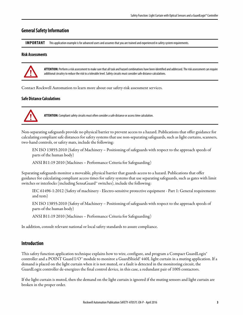
General Safety Information
Risk Assessments
Contact Rockwell Automation to learn more about our safety-risk assessment services.
Safe Distance Calculations
Non-separating safeguards provide no physical barrier to prevent access to a hazard. Publications that offer guidance for calculating compliant safe distances for safety systems that use non-separating safeguards, such as light curtains, scanners, two-hand controls, or safety mats, include the following:
EN ISO 13855:2010 (Safety of Machinery – Positioning of safeguards with respect to the approach speeds of parts of the human body)
ANSI B11:19 2010 (Machines – Performance Criteria for Safeguarding)
Separating safeguards monitor a moveable, physical barrier that guards access to a hazard. Publications that offer guidance for calculating compliant access times for safety systems that use separating safeguards, such as gates with limit switches or interlocks (including SensaGuard™ switches), include the following:
IEC 61496-1:2012 (Safety of machinery - Electro-sensitive protective equipment - Part 1: General requirements and tests)
EN ISO 13855:2010 (Safety of Machinery – Positioning of safeguards with respect to the approach speeds of parts of the human body)
ANSI B11:19 2010 (Machines – Performance Criteria for Safeguarding)
In addition, consult relevant national or local safety standards to assure compliance.
Introduction
This safety function application technique explains how to wire, configure, and program a Compact GuardLogix® controller and a POINT Guard I/O™ module to monitor a GuardShield® 440L light curtain in a muting application. If a demand is placed on the light curtain when it is not muted, or a fault is detected in the monitoring circuit, the GuardLogix controller de-energizes the final control device, in this case, a redundant pair of 100S contactors.
If the light curtain is muted, then the demand on the light curtain is ignored if the muting sensors and light curtain are broken in the proper order.
IMPORTANT This application example is for advanced users and assumes that you are trained and experienced in safety system requirements.
ATTENTION: Perform a risk assessment to make sure that all task and hazard combinations have been identified and addressed. The risk assessment can require additional circuitry to reduce the risk to a tolerable level. Safety circuits must consider safe distance calculations.
ATTENTION: Compliant safety circuits must often consider a safe distance or access time calculation.
Rockwell Automation Publication SAFETY-AT057C-EN-P - April 2016 3

Safety Function: Light Curtain with Optical Sensors and a GuardLogix® Controller
This example uses a Compact GuardLogix controller, but is applicable to any GuardLogix® controller. This example uses a GuardShield 440L light curtain, but is applicable to light curtains that pulse test the OSSD1 and OSSD2 outputs. This example uses RightSight™ optical sensors, but is applicable to any sensors that can be wired into Allen-Bradley® safety inputs in a mode that provides a high (1) signal when not blocked. The SISTEMA calculations shown later in this document would have to be recalculated using the actual products.
Safety Function Realization: Risk Assessment
The required performance level is the result of a risk assessment and refers to the amount of the risk reduction to be carried out by the safety-related parts of the control system. Part of the risk reduction process is to determine the safety functions of the machine. In this application, the performance level required (PLr) by the risk assessment is Category 3, Performance Level d (CAT. 3, PLd), for each safety function. A safety system that achieves CAT. 3, PLd, or higher, can be considered control reliable. Each safety product has its own rating and can be combined to create a safety function that meets or exceeds the PLr.
Light Curtain Safety Function
This application technique describes the operation of a light curtain with muting functionality. There is no muting override in this example.
From: Risk Assessment (ISO 12100)
1. Identification of safety functions
2. Specification of characteristics of each function
3. Determination of required PL (PLr) for each safety function
To: Realization and PL Evaluation
4 Rockwell Automation Publication SAFETY-AT057C-EN-P - April 2016

Safety Function: Light Curtain with Optical Sensors and a GuardLogix® Controller
Safety Function Requirements
Interrupting the light curtain stops and prevents hazardous motion by removal of power to the motor. When the light curtain is reset, hazardous motion and power to the motor do not resume until a secondary action (start button depressed) occurs. Muting of the light curtain is done to allow automatically-fed material to enter the area. Multiple sensors are configured to detect the incoming material and to initiate the muting function. Faults at the light curtain, muting sensors, wiring terminals, or safety controller are detected before the next safety demand.
The safe-distance location of the light curtain must be established so that the hazardous motion can be stopped before the user reaches the hazard.
The safety functions in this application technique each meet or exceed the requirements for Category 3, Performance Level d (CAT. 3, PLd), per ISO 13849-1 and control reliable operation per ANSI B11.19.
Functional Safety Description
Hazardous motion is interrupted or prevented by interrupting the light curtain. The 440L light curtain is wired to a pair of safety inputs of a 1734-IB8S module. The RightSight muting sensors are wired to inputs on the 1734-IB8S module as well. The I/O module is connected via CIP Safety™ over an EtherNet/IP™ network to the Compact GuardLogix® safety controller, catalog number 1768-L43S.
The safety code in the safety processor monitors the status of the safety input using the pre-certified safety instruction Dual Channel Input Stop (DCS). The output of the DCS, along with the two muting sensors, is used as an input to the two sensor asymmetrical muting (TSAM) function block to handle the muting safety function.
When all safety-input interlocks are satisfied, no faults are detected, and the reset button is pressed, a second, certified function block called Configurable Redundant Output (CROUT) controls and monitors feedback for a pair of 100S redundant contactors.
In summary, when the unmuted light curtain is blocked, the contactors drop out. When the light curtain is unblocked, and the reset button is pressed, the contactors are energized.
A properly-muted light curtain can be broken without dropping out the safety contactors. When the light curtain is muted, the muting lamp is energized.
Rockwell Automation Publication SAFETY-AT057C-EN-P - April 2016 5

Safety Function: Light Curtain with Optical Sensors and a GuardLogix® Controller
Bill of Material
This application technique uses these products.
Setup and Wiring
For detailed information on how to install and wire a safety system, refer to the publications listed in the Additional Resources.
System Overview
The 1734-IB8S input module monitors OSSD1 and OSSD2 from the 440L light curtain, and the two RightSight muting sensors. If muting is not active and the light curtain is blocked, OSSD1 and OSSD2 go low (0), and the controller reacts by dropping out the safety contactors.
The 440L light curtain has onboard diagnostics to dynamically test the signal wiring for shorts to 24V DC and channel-to-channel shorts. If a fault occurs, either or both OSSD1 and OSSD2 are set to low (0), and the controller reacts by dropping out the safety contactors.
Shorts to 0V DC (and wire off ) are seen as an open circuit by the 1734-IB8S input module, and the controller reacts by dropping out the safety contactors. If the inputs remain discrepant for longer than the discrepancy time, then the function block (DCS) in the controller declares a fault.
Only after the fault is cleared and the light curtain is cycled (blocked, then unblocked), does the function block reset.
The muting sensors are high (1) when the sensors are not blocked. If any fault occurs, such as a wire being off, the fault causes one of the muting sensors to go low (0) in an improper muting sequence, then the controller reacts by dropping out the safety contactors.
Cat. No. Description Quantity
440L-P4JL0640YD GuardShield™ safety light curtain, Res 14 mm (.55 in.), Pt Ht 640 mm (25.2 in.), 64 beams, integrated laser alignment 1
42EF-B1KBBE-F4 Diffuse background suppression, dark operate, PNP photoelectric sensor, high (1) when target absent 2
889D-F4AC-2 DC micro (M12), female, straight, 4-pin, PVC cable, yellow, unshielded, 22 AWG, 2 m (6.6 ft) 3
889D-F8AB-2 DC micro (M12), female, straight, 8-pin, PVC cable, yellow, unshielded, 24 AWG, 2 m (6.6 ft) 1
800FM-G611MX10 800F reset push button - metal, guarded, blue, R, metal latch mount, one N.O. contact, standard 1
100S-C09ZJ23C Bulletin 100S-C - safety contactors 2
1768-ENBT CompactLogix™ EtherNet/IP bridge module 1
1768-L43S Compact GuardLogix processor, 2.0 MB standard memory, 0.5 MB safety memory 1
1768-PA3 Power supply, 120/240V AC input, 3.5 A @ 24V DC 1
1769-ECR Right end cap/terminator 1
1734-AENT 24V DC Ethernet adapter 1
1734-TB Module base with removable IEC screw terminals 4
1734-IB8S POINT Guard safety input module 1
1734-OB8S POINT Guard safety output module 1
1783-US05T Stratix 2000™ unmanaged Ethernet switch 1
800T-QTH24G Pilot light, 24V DC 2
6 Rockwell Automation Publication SAFETY-AT057C-EN-P - April 2016

Safety Function: Light Curtain with Optical Sensors and a GuardLogix® Controller
Only if the muting sensors and light curtain are blocked in the proper sequence, is muting active. When muting is active, the muting lamp is energized. If the muting lamp is not drawing any current (due to a broken wire or burnt out bulb), the TSAM diagnostic code indicates this condition. This diagnostic is available because the muting sensor is wired from a test output that can be configured for the MUTING LAMP (test outputs 1 and 3 on a 1734-IB8S module).
The final control device in this case is a pair of 100S safety contactors, K1 and K2. The contactors are controlled by a 1734-OBS safety output module. The contactors are wired in a redundant-series configuration. A feedback circuit is wired through the N.O. contacts and back to an input on the 1734-IB8S module to monitor the contactors for proper operation. The contactors cannot restart if the feedback circuit is not in the correct state.
The system has individual reset buttons for resetting faults and safety outputs.
The reset buttons and the contactor feedback circuit are all wired to the 1734-IB8S module in this example. This configuration is not required for functional safety. These three inputs could be wired to a standard input module.
The Clear Area (CA) lamp is wired to test output 1 in this example. This configuration is not required for functional safety. This lamp could be wired to a standard output module.
Safe Distance Calculation
The user must perform a calculation by using this formula to determine the distance between the light curtain and the hazard. The user must use values based on their application, rather than the example calculation shown here.
S = (K x T) + CK = 1600 mm per second (63 in. per second), constant from B11.19-1990T = stopping timeC = Depth penetration factor = 25 mm (.98 in.) for 14 mm (.55 in.) resolution (from documentation)
Stopping time (T) for this example is a summation of the following:a. Light curtain delay = 25 ms (from documentation)b. 1734-IB8S module delay = 16 ms (from documentation)c. The input module connection delay defaults to 4 x RPI; assuming an RPI of 10 ms, the maximum delay = 40
msd. Safety controller delay = safety task watchdog (5 ms) + safety task period (10 ms)e. The output module connection delay defaults to 3 x RPI; assuming an RPI of 10 ms, the maximum delay = 30
msf. 1734-OB8S delay = 6 ms (from documentation)g. Contactor response time = 15 ms (from documentation)h. Actual machine stop time = assume 900 ms for this example
The worst-case reaction time may be calculated assuming there is only a single fault in the control system. This means that only the higher of the two connection-delay values shown above must be included in the time calculation. For this example, 40 ms is used, and the 30 ms is excluded. If you wish to account for multiple faults occurring simultaneously, use both values in the calculation.
The safety controller delay is a combination of the safety task period plus the safety task watchdog. The watchdog accounts for the possibility that the safety code runs right up to, but does not trip, the watchdog. The safety task period accounts for the possibility that the asynchronous scan just ended when the input changed state.
Rockwell Automation Publication SAFETY-AT057C-EN-P - April 2016 7

Safety Function: Light Curtain with Optical Sensors and a GuardLogix® Controller
So to calculate T, add the following:Light curtain delay = 25 ms1734-IB8S module delay = 16 msHigher of input/output module connection delay = 40 ms Safety controller delay = 10+5 = 15 ms1734-OB8S delay = 6 ms Contactor response time = 15 msMeasured actual machine stop time = 900 ms
This makes the total stop time (T) = 1017 msS = (K x T) + C = (63 x 1.017) + 1 = 65.071 in.
Given this example, the light curtain must be placed 65 in. from the hazard.
Safe Distance Calculation to 13855
S = (K x T) + CS = minimum distance, in millimeters (mm)K: a parameter, in millimeters per second (mm/s), derived from data on approach speeds of the body or parts of the bodyT: the overall stopping performance in seconds C: the intrusion distance in mm
In this application technique, the values are:K =1600 mm per second (63 in. per second)T = Sum of light curtain delay = 25 ms 1734-IB8S module delay = 16 msHigher of input/output module connection delay = 40 ms Safety controller delay = 10 + 5 = 15 ms1734-OB8S delay = 6 msContactor response time = 15 msMeasured actual machine stop time = 900 ms
This makes the total stop time (T) = 1017 msC = 8 (d - 14) but not less than 0, where d is the resolution of the light curtain S = 1600 x 1.017 + 8(14 - 14)
The light curtain must not be mounted closer than 1628 mm (approx. 64 in.) from the hazardous motion being guarded against.
8 Rockwell Automation Publication SAFETY-AT057C-EN-P - April 2016

Safety Function: Light Curtain with Optical Sensors and a GuardLogix® Controller
Timing Chart
The diagram provides a visual illustration of the operation of the light curtain.
1
0
1
0
1
0
1
0
1
0
1
0
1
0
1
0
≤ t1≤ t1
2t ≤2t ≤
≤ t3
t1: S1-S2 Time t2: S2-LC Timet3: Maximum Mute Time Restart Type = Manual
Enable Mute
Sensor 1
Sensor 2
Light Curtain
Reset
Output 1
Muting Lamp
Muting Lamp Status
Enable Mute
Sensor 1
Sensor 2
Light Curtain
Reset
Muting Lamp Status
Output 1
Muting Lamp
t1: S1 - S2 Timet3: Maximum Mute Time t2: S2 - LC Time
Restart Type = Manual
Rockwell Automation Publication SAFETY-AT057C-EN-P - April 2016 9

Safety Function: Light Curtain with Optical Sensors and a GuardLogix® Controller
Electrical Schematic
24V DC
24V DC Common
Transmitter Receiver
Safety Reset Fault Reset
*Muting Lamp
*Clear Area Lamp
Brown
Black
Blue
Brown
Black
Blue
*The 24V DC Common wires for the two G lamps are not shown.
10 Rockwell Automation Publication SAFETY-AT057C-EN-P - April 2016

Safety Function: Light Curtain with Optical Sensors and a GuardLogix® Controller
Configuration
The dip switches in the 400L light curtain can remain in the factory default position.
The Compact GuardLogix controller is configured by using RSLogix 5000® software, version 17 or later. You must create a project and add the I/O modules. Then, configure the I/O modules for the correct input and output types. A detailed description of each step is beyond the scope of this document. Knowledge of the RSLogix™ programming environment is assumed.
Configure the Controller and Add I/O Modules
Follow these steps to configure the controller and add I/O modules.1. In RSLogix 5000 software, create a project.
Table 1 - Receiver - Factory Settings
Switch Switch Function Default Setting Description
1 Mode Activation - Combination activates one of the following modes: Guard Only, Start Interlock, Restart Interlock
ON Guard Only
2 ON
3 MPCE: Monitoring Disable ON Disabled
4 Fixed Blanking Activate OFF Disabled
5 Floating Blanking Activate - Single Beam OFF Switches 5 and 6 cannot be activated ON simultaneously
6 Floating Blanking Activate - Two Beams OFF
7 Set Beam Coding OFF Disabled
8 Not Used OFF
Table 2 - Transmitter - Factory Settings
Switch Switch Function Default Setting Description
1 Set Beam Coding OFF Disabled
2 Machine Test Signal OFF OFF: Signal High Active-No connection or connect normally open ON: Signal Low Active-Connect N/C
Rockwell Automation Publication SAFETY-AT057C-EN-P - April 2016 11

Safety Function: Light Curtain with Optical Sensors and a GuardLogix® Controller
2. In the Controller Organizer, add the 1768-ENBT module to the 1768 Bus.
3. Select the 1768-ENBT module, and click OK.
4. Name the module, type its IP address, and click OK.
We used 192.168.1.8 for this application example. Yours may be different.5. Add the 1734-AENT adapter by right-clicking the 1768-ENBT module in the Controller Organizer and
choosing New Module.
12 Rockwell Automation Publication SAFETY-AT057C-EN-P - April 2016

Safety Function: Light Curtain with Optical Sensors and a GuardLogix® Controller
6. Select the 1734-AENT adapter and click OK.
7. Name the module, type its IP address, and click OK.
We used 192.168.1.11 for this application example. Yours may be different.8. Click Change.
Rockwell Automation Publication SAFETY-AT057C-EN-P - April 2016 13

Safety Function: Light Curtain with Optical Sensors and a GuardLogix® Controller
9. Set the Chassis Size as 3 for the 1734-AENT adapter and click OK.
Chassis size is the number of modules that are inserted in the chassis. The 1734-AENT adapter is considered to be in slot 0, so for one input and one output module, the chassis size is 3.
10. In the Controller Organizer, right-click the 1734-AENT adapter and choose New Module.
11. Expand Safety, select the 1734-IB8S module, and click OK.12. In the New Module dialog box, name the device IB8S, and click Change.
14 Rockwell Automation Publication SAFETY-AT057C-EN-P - April 2016

Safety Function: Light Curtain with Optical Sensors and a GuardLogix® Controller
13. When the Module Definition dialog box opens, make edits so that it appears as shown below, and click OK.
Setting the output data to Test means that you can use the test outputs as standard outputs, and we are driving the Clear Area lamp with a test output in this example.
14. Close the Module Properties dialog box by clicking OK.15. Repeat steps 10…14 to add the 1734-OB8S safety output module. 16. Name the module OB8S.
This module is in slot 2, and Combined Status-Readback-Power is selected for Input Status.
Rockwell Automation Publication SAFETY-AT057C-EN-P - April 2016 15

Safety Function: Light Curtain with Optical Sensors and a GuardLogix® Controller
Configure the I/O Modules
Follow these steps to configure the POINT Guard I/O™ modules.
1. In the Controller Organizer, right-click the 1734-IB8S module and choose Properties.2. Click the Test Output tab, and configure the module as shown.
if
Test output 1 is being used to drive the Clear Area lamp, which is a standard output. Test output 2 is sourcing the feedback circuit, and is being pulse tested to detect shorts to 24V DC. Test output 3 is driving the muting lamp. The muting lamp configuration tests for no current to indicate a burnt-out bulb.
3. Click the Input Configuration tab for the 1734-IB8S module, and configure the module as shown.
Inputs 0/1 monitor the light curtain. Inputs 2/3 monitor the muting lamps. Inputs 4/5 monitor the reset buttons. Input 7 is the contactor-monitoring circuit. Recall that input 7 is being sourced from Test Output 2. There is no difference when an input channel is configured for safety or standard. It is used or documentation.
4. Click OK.5. In the Controller Organizer, right-click the 1734-OB8S module, and choose Properties.
16 Rockwell Automation Publication SAFETY-AT057C-EN-P - April 2016
Safety Function: Light Curtain with Optical Sensors and a GuardLogix® Controller
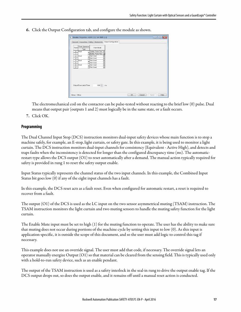
6. Click the Output Configuration tab, and configure the module as shown.
The electromechanical coil on the contactor can be pulse-tested without reacting to the brief low (0) pulse. Dual means that output pair (outputs 1 and 2) must logically be in the same state, or a fault occurs.
7. Click OK.
Programming
The Dual Channel Input Stop (DCS) instruction monitors dual-input safety devices whose main function is to stop a machine safely, for example, an E-stop, light curtain, or safety gate. In this example, it is being used to monitor a light curtain. The DCS instruction monitors dual-input channels for consistency (Equivalent - Active High), and detects and traps faults when the inconsistency is detected for longer than the configured discrepancy time (ms). The automatic-restart type allows the DCS output (O1) to reset automatically after a demand. The manual action typically required for safety is provided in rung 1 to reset the safety output enable.
Input Status typically represents the channel status of the two input channels. In this example, the Combined Input Status bit goes low (0) if any of the eight input channels has a fault.
In this example, the DCS reset acts as a fault reset. Even when configured for automatic restart, a reset is required to recover from a fault.
The output (O1) of the DCS is used as the LC input on the two sensor asymmetrical muting (TSAM) instruction. The TSAM instruction monitors the light curtain and two muting sensors to handle the muting safety function for the light curtain.
The Enable Mute input must be set to high (1) for the muting function to operate. The user has the ability to make sure that muting does not occur during portions of the machine cycle by setting this input to low (0). As this input is application-specific, it is outside the scope of this document, and so the user must add logic to control this tag if necessary.
This example does not use an override signal. The user must add that code, if necessary. The override signal lets an operator manually energize Output (O1) so that material can be cleared from the sensing field. This is typically used only with a hold-to-run safety device, such as an enable pendant.
The output of the TSAM instruction is used as a safety interlock in the seal-in rung to drive the output enable tag. If the DCS output drops out, so does the output enable, and it remains off until a manual reset action is conducted.
Rockwell Automation Publication SAFETY-AT057C-EN-P - April 2016 17

Safety Function: Light Curtain with Optical Sensors and a GuardLogix® Controller
The Configurable Redundant Output (CROUT) instruction controls and monitors redundant outputs. Essentially, this instruction verifies that feedback follows the safety outputs appropriately. For the negative feedback used in this example, if the outputs are high (1), the feedback should be low (0), and vice versa. In this example, the feedback has 500 ms to change to the proper state. Since only one feedback circuit is being used, the feedback tag is used for both Feedback 1 and 2.
The two output tags from the CROUT instruction are used to drive the contactor outputs on the 1734-OB8S module.
O1
FP
Dual Channel Input StopDCS Zone1_LCSafety Function LIGHT CURTAINInput Type EQUIVALENT - ACTIVE HIGHDiscrepancy Time (Msec) 250Restart Type AUTOMATICCold Start Type AUTOMATICChannel A AENT:1:I.Pt00Data ??Channel B AENT:1:I.Pt01Data ??Input Status AENT:1:I.CombinedInputStatus ??Reset AENT:1:I.Pt05Data ??
DCS
O1
ML
CA
FP
Two Sensor Asymmetrical MutingTSAM Zone1_TSAMRestart Type AUTOMATICS1-S2 Time (Msec) 500S2-LC Time (Msec) 500Maximum Mute Time (Sec) 3000Maximum Override Time (Sec) 0Light Curtain Zone1_LC.O1 0Sensor 1 AENT:1:I.Pt02Data ??Sensor 2 AENT:1:I.Pt03Data ??Enable Mute Zone1_LC_Mute_Enable 0Override NO_override 0Input Status AENT:1:I.CombinedInputStatus ??Muting Lamp Status A ENT:1:I.Muting03Status ??Reset AENT:1:I.Pt05Data ??
TSAM
AENT:1:I.Pt04Data
SBOB
One Shot FallingStorage Bit Wrk_Zone1_OSFOutput Bit Wrk_Zone1_FallingEdge
OSF
Wrk_Zone1_FallingEdge
Cmd_Zone1_OutputEnable
Zone1_TSAM.O1/
Zone1_K1K2.FP Cmd_Zone1_OutputEnable
18 Rockwell Automation Publication SAFETY-AT057C-EN-P - April 2016

Safety Function: Light Curtain with Optical Sensors and a GuardLogix® Controller
Falling Edge Reset
ISO 13849-1 stipulates that instruction reset functions must occur on falling edge signals. To comply with this requirement, a One Shot Falling (OSF) instruction is used on the reset rung. Then the OSF instruction Output Bit tag is used as the reset bit for the Output Enable rung.
Calculation of the Performance Level
When configured correctly, this muting safety function can achieve a safety rating of Category 4, Performance Level e (CAT. 4, PLe), according to ISO 13849-1: 2008, as calculated by using the Safety Integrity Software Tool for the Evaluation of Machine Applications (SISTEMA).
The functional safety specifications of the project call for a minimum structure of CAT. 3 and a minimum Performance Level of PLd. A PFHd of less than 1.0 E-06 for the overall safety function is required for PLd.
The overall safety function value is shown below.
O1
O2
FP
Configurable Redundant OutputCROUT Zone1_K1K2Feedback Type NEGATIVEFeedback Reaction Time (Msec) 500Actuate Cmd_Zone1_OutputEnable 0Feedback 1 AENT:1:I.Pt07Data ??Feedback 2 AENT:1:I.Pt07Data ??Input Status AENT:1:I.CombinedInputStatus ??Output Status AENT:2:I.CombinedOutputStatus ??Reset AENT:1:I.Pt05Data ??
CROUT
Zone1_K1K2.O1 Zone1_K1K2.O2 AENT:2:O.Pt00Data AENT:2:O.Pt01Data
Zone1_TSAM.ML AENT:1:O.Test03Data
Zone1_TSAM.CA AENT:1:O.Test01Data
Rockwell Automation Publication SAFETY-AT057C-EN-P - April 2016 19

Safety Function: Light Curtain with Optical Sensors and a GuardLogix® Controller
The individual subsystem values are shown below.
The light curtain muting safety function can be modeled as follows.
Calculations are based on one operation of the light curtain per hour, or 8,760 operations of the contactors per year.
The measures against Common Cause Failure (CCF) are quantified using the scoring process outlined in Annex F of ISO 13849-1. For the purposes of the PL calculation, the required score of 65 needed to fulfill the CCF requirement is considered to be met. The complete CCF scoring process must be done when implementing this example.
Because the contactors are electromechanical devices, the safety contactor data includes the following:• Mean Time to Failure, dangerous (MTTFd)• Diagnostic Coverage (DCavg)• Common Cause Failure (CCF)
Electromechanical devices' functional safety evaluations include the following:• How frequently they are operated• Whether they are effectively monitored for faults• Whether they are properly specified and installed
SISTEMA calculates the MTTFd by using B10d data provided for the contactors along with the estimated frequency of use, entered during the creation of the SISTEMA project.
The DCavg (99%) for the contactors is selected from the Output Device table of ISO 13849-1 Annex E, Direct Monitoring.
The CCF value is generated by using the scoring process outlined in Annex F of ISO 13849-1. The complete CCF scoring process must be performed when actually implementing an application. A minimum score of 65 must be achieved.
Subsystem 1 Subsystem 2 Subsystem 3 Subsystem 4 Subsystem 5 Subsystem 6
Input Logic Output
42EF
42EF
440L Light Curtain 1734-IB8S 1734-OB8S1768-L43S
K1 100S
K2 100S
20 Rockwell Automation Publication SAFETY-AT057C-EN-P - April 2016

Safety Function: Light Curtain with Optical Sensors and a GuardLogix® Controller
Verification and Validation Plan
Verification and validation play important roles in the avoidance of faults throughout the safety system design and development process. ISO 13849-2 sets the requirements for verification and validation. The standard calls for a documented plan to confirm that all of the safety functional requirements have been met.
Verification is an analysis of the resulting safety control system. The Performance Level (PL) of the safety control system is calculated to confirm that the system meets the required Performance Level (PLr) specified. The SISTEMA software is typically used to perform the calculations and assist with satisfying the requirements of ISO 13849-1.
Validation is a functional test of the safety control system to demonstrate that the system meets the specified requirements of the safety function. The safety control system is tested to confirm that all of the safety-related outputs respond appropriately to their corresponding safety-related inputs. The functional test includes normal operating conditions in addition to potential fault injection of failure modes. A checklist is typically used to document the validation of the safety control system.
Before validating the GuardLogix safety system, confirm that the safety system and safety application program have been designed in accordance with the GuardLogix Controller Systems Safety Reference Manual, publication 1756-RM093, and the GuardLogix Safety Application Instruction Set Safety Reference Manual, publication 1756-RM095.
Verification and Validation Checklist
General Machinery Information
Machine Name/Model Number
Machine Serial Number
Customer Name
Test Date
Tester Name
Schematic Drawing Number
Controller Name
Safety Signature ID
Safety Network
RSLogix5000 Software
Safety Control System GuardLogix Modules Firmware Revision
GuardLogix Safety 1768-L43S
CompactLogix Ethernet 1768-ENBT
POINT I/O™ Ethernet 1734-AENT
POINT I/O Input Module 1734-IB8S
POINT I/O Output Module 1734-OB8S
Safety System Configuration and Wiring Verification
Test Step Verification Pass/Fail Changes/Modifications
1 Verify that the safety system has been designed in accordance with the GuardLogix Controller Systems Safety Reference Manual, publication 1756-RM093.
2Verify that the safety application program has been designed in accordance with the GuardLogix Safety Application Instruction Set Safety Reference Manual, publication 1756-RM095.
Rockwell Automation Publication SAFETY-AT057C-EN-P - April 2016 21

Safety Function: Light Curtain with Optical Sensors and a GuardLogix® Controller
3 Visually inspect the safety system network and verify that the I/O is wired as documented in the schematics.
4 Visually inspect the light curtain and verify that it is configured as documented.
5 Visually inspect the RSLogix 5000 program to verify that the safety system network and I/O module configuration are configured as documented.
6Visually inspect the RSLogix 5000 application program to verify that suitable safety-certified instructions are used. The logic must be readable, understandable, and testable with the aid of clear comments.
7 Verify that all input devices are qualified by cycling their respective actuators. Monitor the status in the RSLogix 5000 Controller Tags window.
8 Verify that all output devices are qualified by cycling their respective actuators. Monitor the status in the RSLogix 5000 Controller Tags window.
Normal Operation Verification - The safety system responds properly to all normal Start, Stop, Enabling, and Reset commands.
Test Step Verification Pass/Fail Changes/Modifications
1Initiate a Start command. Both contactors energize for a normal machine run condition. Verify proper machine status indication and safety application program indication.
2Initiate a Stop command. Both contactors de-energize for a normal machine stop condition. Verify proper machine status indication and safety application program indication.
3While the system continues to run, initiate a muting sequence and interrupt the light curtain. Both contactors remain energized for a normal, safe condition. Verify proper machine status indication and safety application program indication.
4While the system continues to run, interrupt the light curtain. Both contactors de-energize and open for a normal safe condition. Verify proper machine status indication and safety application program indication. Repeat for all light curtains.
5
While the system is stopped, interrupt the light curtain and initiate a Start command. Both contactors remain de-energized and open for a normal, safe condition. Verify proper machine status indication and safety application program indication. Repeat for all light curtains.
6 Initiate a Reset command. Both contactors remain de-energized. Verify proper machine status indication and safety application program indication.
Validation of Safe Response to Abnormal Operation - The safety system responds properly to all foreseeable faults with corresponding diagnostics.
Light Curtain, Muting Sensor Input Tests
Test Step Validation Pass/Fail Changes/Modifications
1
While the system continues to run, remove the light curtain channel 1 wire from the safety I/O. Both contactors de-energize. Verify proper machine status indication and safety application program indication. Verify that the system cannot be reset and restarted with the fault. Restore channel 1 and repeat for channel 2.
2
While the system continues to run, short the light curtain channel 1 of the safety I/O to 24V DC. Both contactors de-energize. Verify proper machine status indication and safety application program indication. Verify that the system cannot be reset and restarted with the fault. Restore channel 1 and repeat for channel 2.
3
While the system continues to run, short the light curtain channel 1 of the safety I/O to 0V DC. Both contactors de-energize. Verify proper machine status indication and safety application program indication. Verify that the system cannot be reset and restarted with the fault. Restore channel 1 and repeat for channel 2.
4
While the system continues to run, short the light curtain channels 1 and 2 of the safety I/O. Both contactors de-energize. Verify proper machine status indication and safety application program indication. Verify that the system cannot be reset and restarted with the fault. Restore channel 1 and 2 wiring.
5While the system continues to run, remove the muting sensor 1 wire from the safety I/O. Both contactors de-energize. Verify proper machine status indication and safety application program indication. Restore sensor 1 and repeat for sensor 2.
Verification and Validation Checklist
22 Rockwell Automation Publication SAFETY-AT057C-EN-P - April 2016

Safety Function: Light Curtain with Optical Sensors and a GuardLogix® Controller
6
While the system continues to run, short the muting sensor 1 wire of the safety I/O to 24V DC. Both contactors de-energize. Verify proper machine status indication and safety application program indication. Verify that the system cannot be reset and restarted with the fault. Restore sensor 1 and repeat for sensor 2.
7
While the system continues to run, short the muting sensor 1 wire of the safety I/O to 0V DC. Both contactors de-energize. Verify proper machine status indication and safety application program indication. Verify that the system cannot be reset and restarted with the fault. Restore sensor 1 and repeat for sensor 2.
8
While the system continues to run, short the muting sensors 1 and 2 of the safety I/O. Both contactors de-energize. Verify proper machine status indication and safety application program indication. Verify that the system cannot be reset and restarted with the fault. Restore sensor 1 and 2 wiring.
9
While the system continues to run, initiate an incorrect muting sequence. Both contactors de-energize. Verify proper machine status indication and safety application program indication. Verify that the system cannot be reset and restarted with the fault. Restore sensor 1 and 2 wiring.
Validation of Safe Response to Abnormal Operation - The safety system responds properly to all foreseeable faults with corresponding diagnostics.
GuardLogix Controller, Network Tests
Test Step Validation Pass/Fail Changes/Modifications
1While the system continues to run, remove the Ethernet network connection between the safety I/O and the controller. All contactors de-energize. Verify proper machine status indication and I/O connection status in the safety application program.
2Restore the safety I/O module network connection and allow time to re-establish communication. Verify the Connection Status Bit in the safety application program. Repeat for all safety I/O connections.
3
While the system continues to run, switch the controller out of Run mode. All contactors de-energize. Return the key switch back to Run mode. All contactors remain de-energized. Verify proper machine status indication and safety application program indication.
Validation of Safe Response to Abnormal Operation - The safety system responds properly to all foreseeable faults with corresponding diagnostics.
Safety Contactor Output Tests
Test Step Verification and Validation Pass/Fail Changes/Modifications
1Initiate a Start command. Both contactors energize for a normal machine run condition. Verify proper machine status indication and safety application program indication.
2
While the system continues to run, remove the contactor feedback from the safety I/O. All contactors remain energized. Initiate a Stop command and attempt a Reset command. The system does not restart or reset. Verify proper machine status indication and safety application program indication.
3
While the system continues to run, short the contactor feedback to the safety I/O. All contactors remain energized. Initiate a Stop command and attempt a Reset command. The system does not restart or reset. Verify proper machine status indication and safety application program indication.
Verification and Validation Checklist
Rockwell Automation Publication SAFETY-AT057C-EN-P - April 2016 23

Safety Function: Light Curtain with Optical Sensors and a GuardLogix® Controller
Additional Resources
These documents contain more information about related products from Rockwell Automation.
You can view or download publications at http://www.rockwellautomation.com/literature/. To order paper copies of technical documentation, contact your local Allen-Bradley distributor or Rockwell Automation sales representative.
Resource Description
Compact GuardLogix Controllers User Manual, Publication 1768-UM002 Provides information on how to configure, operate, and maintain Compact GuardLogix controllers.
POINT Guard I/O Safety Modules User Manual, Publication 1734-UM013 Provides information on how to install, configure, and operate POINT Guard I/O modules.
GuardLogix Controller Systems Safety Reference Manual, Publication 1756-RM093 Contains detailed requirements for how to achieve and maintain safety ratings with the GuardLogix controller system.
GuardLogix Safety Application Instruction Set Safety Reference Manual, Publication 1756-RM095
Provides detailed information on the GuardLogix Safety Application Instruction Set.
Safety Accelerator Toolkit for GuardLogix Systems Quick Start Guide, Publication IASIMP-QS005
Provides a step-by-step guide on how to use the design, programming, and diagnostic tools in the Safety Accelerator Toolkit.
Industrial Automation Wiring and Grounding Guidelines, publication 1770-4.1 Provides general guidelines on how to install a Rockwell Automation® industrial system.
Safety Products Catalog, publication S117-CA001Website http://www.rockwellautomation.com/rockwellautomation/catalogs/overview.page
Provides information about Rockwell Automation safety products.
Product Certifications website, http://www.rockwellautomation.com/global/certification/overview.page
Provides declarations of conformity, certificates, and other certification details.
24 Rockwell Automation Publication SAFETY-AT057C-EN-P - April 2016

Safety Function: Light Curtain with Optical Sensors and a GuardLogix® Controller
Notes:
Rockwell Automation Publication SAFETY-AT057C-EN-P - April 2016 25

Allen-Bradley, CompactLogix, GuardLogix, GuardShield, LISTEN. THINK. SOLVE, POINT Guard I/O, POINT I/O, RSLogix, RSLogix 5000, RightSight, Rockwell Automation, Rockwell Software, SensaGuard, and Stratix 2000 are trademarks of Rockwell Automation, Inc.Trademarks not belonging to Rockwell Automation are property of their respective companies.CIP Safety and EtherNet/IP are trademarks of ODVA, Inc.
Publication SAFETY-AT057C-EN-P - April 2016
Rockwell Automation Support
Use the following resources to access support information.
Documentation Feedback
Your comments will help us serve your documentation needs better. If you have any suggestions on how to improve this document, complete the
Technical Support Center Knowledgebase Articles, How-to Videos, FAQs, Chat, User Forums, and Product Notification Updates. www.rockwellautomation.com/knowledgebase
Local Technical Support Phone Numbers Locate the phone number for your country. www.rockwellautomation.com/global/support/get-support-now.page
Direct Dial CodesFind the Direct Dial Code for your product. Use the code to route your call directly to a technical support engineer.
www.rockwellautomation.com/global/support/direct-dial.page
Literature Library Installation Instructions, Manuals, Brochures, and Technical Data. www.rockwellautomation.com/literature
Product Compatibility and Download Center (PCDC)
Get help determining how products interact, check features and capabilities, and find associated firmware.
www.rockwellautomation.com/global/support/pcdc.page
Rockwell Otomasyon Ticaret A.Ş., Kar Plaza İş Merkezi E Blok Kat:6 34752 İçerenköy, İstanbul, Tel: +90 (216) 5698400
Rockwell Automation maintains current product environmental information on its website at http://www.rockwellautomation.com/rockwellautomation/about-us/sustainability-ethics/product-environmental-compliance.page.
For more information onSafety Function Capabilities, visit:http://marketing.rockwellautomation.com/safety/en/safety_functions
Supersedes Publication SAFETY-AT057B-EN-P - January 2013 Copyright © 2016 Rockwell Automation, Inc. All rights reserved. Printed in the U.S.A.