Embed Size (px)
Citation preview

36
Abstract:The area where a natural gas pipeline is constructed
spreads out to the earthquake or the permafrost area. Application of the Strain-Based Design (SBD) is apply-ing to the pipeline design constructed in such areas. Conventionally, in the safety assessment of a pipeline, although stress-based design assumed brittle or ductile fracture due to internal pressure, SBD deals with the compressive buckling or subsequent large deformation until final rupture. While outlining the integrity assess-ment technology developed for linepipes adapting to Stress-Based and Strain-Based Designs, the perfor-mance of the high-strain linepipe “HIPERTM” developed for SBD is also described.
1. Introduction
Natural gas is an energy source with abundant reserves and low environmental impacts. Given these advantages, demand and consumption have increased steadily in recent years, and accompanying this trend, development of new gas fields is progressing. However, with natural gas production now expanding into regions far from consuming areas, an increasing number of long-distance pipelines are either under construction or in the planning stage. From the viewpoints of economy and construction site, there is a tendency toward high pres-sure operation and use of high strength materials in these pipelines1).
The environments for pipeline construction are also expected to become more severe. Pipelines are now extending into seismic or permafrost regions2), increas-ing the importance of pipeline safety assessment.
HIPERTM is a linepipe with excellent deformability which was developed by JFE Steel with the aim of improving the safety of high strength pipelines in these construction environments to the same level as that of conventional strength pipelines or higher3–5).
This paper outlines the results of previous research on various failure modes, which was carried out in order to secure the safety of natural gas pipelines. As recent trends in safety in new construction environments, the current status of research to incorporate strain-based design (SBD) in gas pipelines, the results of demonstra-tion tests of the deformability of HIPERTM in a full-scale bending test and full-scale pressurized tension test, and a concept of safety assessment which considers failure modes are also presented.
2. ConceptofSafetyunderStress-BasedDesign
From an early date, safety against gas pipeline failure was controlled in three stages, even in the unlikely event of accidental destruction of a pipeline by third-party construction, etc., using circumferential stress due to gas pressure as the applied stress. These three stages are assessed by full-scale and small-scale tests based on the following concept: (1) Prevention of brittle fracture propagation by specifying the shear area fraction in the drop weight tear test (DWTT), (2) Prevention of running ductile fracture by specifying critical stress, and (3) Pre-vention of running ductile fracture by Charpy or DWTT absorbed energy specification. Table1 summarizes the full-scale test methods and frequently-used small-scale test methods. Basically, fracture prevention performance is confirmed by large-scale structural tests using full-scale pipes, and for practical purposes, quality control of
JFETECHNICALREPORTNo.18(Mar.2013)
Safety and Integrity Assessment Technology for Linepipe†
IGI Satoshi*1 MURAOKA Ryuji*2 MASAMURA Katsumi*3
† Originally published in JFE GIHO No. 29 (Feb. 2012), p. 34–40 *2 Staff Manager, Welded Pipe Sec., Products Design & Quality Control for Steel Products Dept., West Japan Works, JFE Steel
*1 Dr. Eng., Senior Researcher Deputy General Manager, Joining & Strength Res. Dept., Steel Res. Lab., JFE Steel
*3 Dr. Eng., Senior Staff General Manager, Tubular Products Business Planning Dept., JFE Steel

JFETECHNICALREPORTNo.18(Mar.2013) 37
Safety and Integrity Assessment Technology for Linepipe
individual linepipes is performed by small-scale tests.
2.1 PreventionofBrittleCrackPropagation
Research on prevention of fracture in gas pipelines began in the 1950s, occasioned by a long-distance brittle crack propagation accident in a gas pipeline. Focusing on the brittle-ductile transition behavior of the fracture surface, Eiber6,7) compared the shear area fraction of brittle fracture in full-scale pipes and Charpy impact test pieces, and found that the Charpy test tends to give an assessment result on the unsafe side. As this was thought to be caused by the difference in the thickness of the test piece and the actual pipe, the press notch DWTT was proposed. Based on the results of full-scale tests, a crite-rion of 85% shear area fraction in the press notch DWTT, in which the shear area transition curve shows good agreement with actual pipes, was proposed and established as a material specification. Photo1 shows the fracture appearance of partial-gas burst test.
2.2 PreventionofRunningDuctileFracture
It had been thought that long distance propagation of cracks could be prevented by assuming ductile fracture as the fracture mode. However, in the 1970s, a phenom-enon in which ductile cracks propagate at high speed over a long distance reaching 300 m was confirmed. This phenomenon is called running ductile fracture. Because the sustained gas pressure in a pipeline contin-ues to supply the plastic deformation and crack forma-tion energy necessary for propagation of a ductile crack, ductile crack propagates at a high speed of 100–500 m/s.
In a full-scale hydrostatic test using notched specimens, Kiefner et al.8) showed that the transition to running fracture (rupture) occurs after stable growth of a ductile crack from the notch tip, and proposed the following Eq. (1) for assessment of the critical stress for this phenom-enon (critical stress for rupture):
where, σ0 is the flow stress of a pipe, σh* is circumferen-
tial stress, Mt is a bulging factor, Cv is Charpy upper shelf energy, Ac is the fracture surface area of a Charpy test specimen, and c is the half-length of a through-thickness notch, and E is Young’s modulus.
Research was carried out on assessment methods aimed at using the material itself to arrest ductile cracks before long-distance propagation of a running ductile fracture. Beginning in the 1970s, many gas burst tests were carried out using full-scale pipeline specimens, as illustrated in Photo2, and the Battelle method9,10), 2-curve methods were developed, as represented by the discriminant analysis assessment method.
High Strength Line Pipe Committee (HLP) of the Iron and Steel Institute of Japan, in which both Kawa-saki Steel and NKK participated (the two companies merged to form JFE Steel), further developed the Bat-telle 2-curve method, and proposed a simulation tech-nique for analyzing changes in the propagation speed and crack arrest distance accompanying crack prog-ress11,12). This HLP 2-curve method is a calculation tech-nique in which the propagation distance of a crack is calculated by time integration of the crack propagation and pressure drop that occur in micro time steps based on a material resistance curve and gas decompression curve, and crack arrest is assumed to occur when the pressure at the crack tip achieves the arrest pressure. High Strength Line Pipe Committee reviewed material resistance curves and adopted the absorbed energy in the pre-crack DWTT, in which a ductile crack is introduced at the notch tip, as the material toughness. The relational equation with Charpy absorbed energy is given by Eq. (4).
Table 1 Small and full-pipe tests for stress-based design
Failure types Portion Small tests Full-pipe test
Brittle fracture
Base metal PN-DWTT Partial-gas burst test
Seam weld CTOD, CharpyHydro static test
(At low temperature)
Running ductile fracture Base metal Charpy energy,
SPC-DWTT energy Gas burst test
PN-DWTT: Press notched-Drop weight tear testCTOD: Crack tip opening displacementSPC-DWTT: Static precracked-DWTT
Photo 1 Fracture appearance of partial-gas burst test Photo 2 Fracture appearance of full-scale gas burst test

38 JFETECHNICALREPORTNo.18(Mar.2013)
Safety and Integrity Assessment Technology for Linepipe
where, Vc is the crack propagation speed, σflow is flow stress (average value of yield stress and tensile strength), Dp is the pre-crack DWTT absorbed energy, Ap is the fracture surface area of the DWTT test specimen, P is the pressure at the crack position, Pa is the crack arrest pressure, D is the pipe diameter, and t is the pipe wall thickness.
However, the material resistance curve used in the HLP 2-curve method was obtained by gas burst tests with API X70 line pipe (API: The American Petroleum Institute) with an outer diameter of 48 inches (1 219 mm) and wall thickness of 18.4 mm. Although crack propagation and arrest behavior can be estimated for pipelines with similar strength and dimensions, the predictive accuracy of this method decreases when high strength materials exceeding X80 and different outer diameters are used in the pipeline being evaluated. Therefore, JFE Steel developed an independent program using the HLP 2-curve method as the basic theory and incorporating the results of recent research13). Specifi-cally, the constants of the material resistance curve are given as functions of the dimensions of the pipeline, a propagation energy fraction was adopted in materials with high absorbed energy, the initial conditions of the crack propagation distance calculations were reviewed, etc.
Figure1 is an example of an analysis of burst tests performed by the Japan Gas Association14). In spite of the fact that the pipe used in these tests was a compara-tively small-diameter X80 grade pipe, satisfactory pre-
dictions are given for both the crack propagation speed and the crack arrest distance15).
3. ConceptofSafetyunderStrain-basedDesign(SBD)
3.1 PipelineDamageModesinSBD
Permafrost regions are divided into three types of permafrost, i.e., continuous permafrost area, discontinu-ous permafrost area, and sporadic permafrost area. Among these, in discontinuous permafrost zones, there are cases in which frost heave and thaw settlement occur due to the existence of pipelines. Frost heave is a phe-nomenon in which a pipeline passing through soil that is not frozen causes the surrounding soil to freeze and rise. Conversely, thaw settlement is a phenomenon which occurs when a pipeline passing through frozen soil melts the permafrost, causing the ground to settle while also generating melting strain. Although large bending defor-mation of pipelines due to these phenomena is a con-cern, it is difficult to completely prevent frost heave and thaw settlement. Therefore, research has been carried out, mainly in North America, with the aim of incorpo-rating SBD in pipeline design, also considering the eco-nomics of pipeline construction and operation16–20).
In pipelines which are to be laid in seismic and per-mafrost regions, an allowance for large deformation due to alteration of the ground conditions is required. On the other hand, because the deformation properties (elonga-tion, work hardening) of pipeline materials decrease in higher grade pipes, it becomes more difficult to secure deformability. Therefore, research aimed at applying SBD to gas pipelines has been carried out, focusing mainly on high grade pipelines of X80 and higher. As the damage and failure modes, the objects of study are local buckling of the pipe base material under compres-sive strain, and rupture initiating from a girth weld defect under tensile strain.
3.2 AssessmentofPipelineBucklingLimitUsingLarge-ScaleBendingTestRig
JFE Steel developed a large-scale bending test rig in order to assess the properties of linepipes which are to be used under SBD. Figure2 shows an overview of the test rig, which consists of two moment arms, an oil hydraulic jack which is used to drive the moving arm, and the main frame, which secures the device as a whole. The test rig is also designed so that internal pres-sure can be applied to the test pipe during the bending test using a water hydraulic pump. The test pipe is welded between the two moment arms, and bending moment is generated in the pipe by movement of the ends of the moment arms. Table2 shows the main spec-ifications of the bending test rig.
Propagation distance (m)
500
400
Cra
ck v
eloc
ity (m
/s)
300
200
100
026.9 m
Backfill: 0.5 m
Backfill: 1.0 m
44.8 m
Exp.Calc.
50 40 30 20 10 0 10 20 30 40 50
Fig. 1 Comparison of full-scale burst test and simulation results
JFETECHNICALREPORTNo.18(Mar.2013) 39
Safety and Integrity Assessment Technology for Linepipe
A bending test of a girth welded joint was performed with an X80 linepipe having an outer diameter of 48 inches (1 219 mm) and a wall thickness of 22 mm. The length of the test pipe was 8 000 mm, which corresponds to 6.7 times the pipe diameter. Bending moment was applied to the test pipes section while maintaining a constant internal pressure by water pressure. The design factor, which is calculated by the magnitude of circum-ferential stress for the specific minimum yield strength (SMYS) at an internal pressure of 12 MPa, was set at 60%. The test pipes were JFE Steel’s high deformability steel pipe HIPERTM and a conventional material. In the case of HIPERTM, a bending test of a girth welded joint was also performed. The tensile properties of the tested pipes are shown in Table3.
The bending moment was calculated from the load of the hydraulic jack and the length of the moment arms, as shown in Eq. (5).
where, Mpipe is the bending moment acting on the pipe,
Fjack is the load of the hydraulic jack, Larm is the length of the moment arms, and δy is the displacement of the tested pipe by bending deformation.
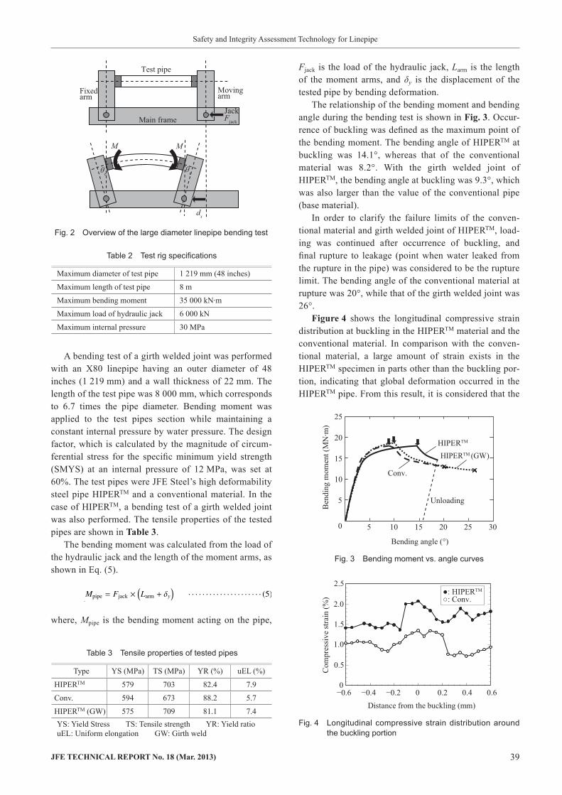
The relationship of the bending moment and bending angle during the bending test is shown in Fig.3. Occur-rence of buckling was defined as the maximum point of the bending moment. The bending angle of HIPERTM at buckling was 14.1°, whereas that of the conventional material was 8.2°. With the girth welded joint of HIPERTM, the bending angle at buckling was 9.3°, which was also larger than the value of the conventional pipe (base material).
In order to clarify the failure limits of the conven-tional material and girth welded joint of HIPERTM, load-ing was continued after occurrence of buckling, and final rupture to leakage (point when water leaked from the rupture in the pipe) was considered to be the rupture limit. The bending angle of the conventional material at rupture was 20°, while that of the girth welded joint was 26°.
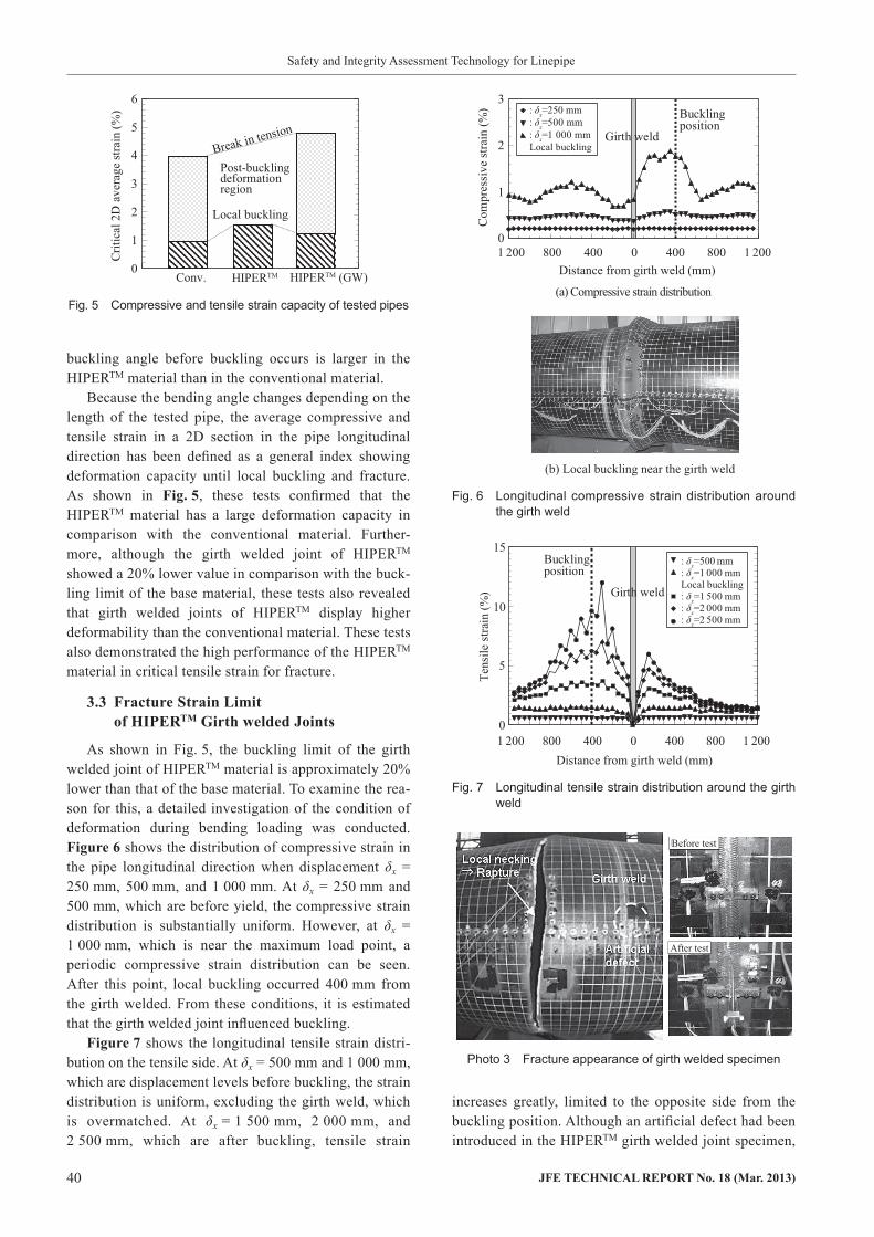
Figure4 shows the longitudinal compressive strain distribution at buckling in the HIPERTM material and the conventional material. In comparison with the conven-tional material, a large amount of strain exists in the HIPERTM specimen in parts other than the buckling por-tion, indicating that global deformation occurred in the HIPERTM pipe. From this result, it is considered that the
Table 2 Test rig specifications
Maximum diameter of test pipe 1 219 mm (48 inches)
Maximum length of test pipe 8 m
Maximum bending moment 35 000 kN·m
Maximum load of hydraulic jack 6 000 kN
Maximum internal pressure 30 MPa
Jack
dx
Fjack
MM
Movingarm
Test pipe
Fixedarm
Main frame
θeθe
Fig. 2 Overview of the large diameter linepipe bending test
0
5
10
15
20
25
Ben
ding
mom
ent (
MN
·m)
Bending angle (°)
Unloading
HIPERTM
HIPERTM (GW)
Conv.
5 10 15 20 25 30
Fig. 3 Bending moment vs. angle curves
0
0.5
1.0
1.5
2.0
2.5
Com
pres
sive
stra
in (%
)
Distance from the buckling (mm)−0.6 −0.4 0.20−0.2 0.4 0.6
●: HIPERTM
○: Conv.
Fig. 4 Longitudinal compressive strain distribution around the buckling portion
Table 3 Tensile properties of tested pipes
Type YS (MPa) TS (MPa) YR (%) uEL (%)
HIPERTM 579 703 82.4 7.9
Conv. 594 673 88.2 5.7
HIPERTM (GW) 575 709 81.1 7.4YS: Yield Stress TS: Tensile strength YR: Yield ratiouEL: Uniform elongation GW: Girth weld
40 JFETECHNICALREPORTNo.18(Mar.2013)
Safety and Integrity Assessment Technology for Linepipe
buckling angle before buckling occurs is larger in the HIPERTM material than in the conventional material.
Because the bending angle changes depending on the length of the tested pipe, the average compressive and tensile strain in a 2D section in the pipe longitudinal direction has been defined as a general index showing deformation capacity until local buckling and fracture. As shown in Fig.5, these tests confirmed that the HIPERTM material has a large deformation capacity in comparison with the conventional material. Further-more, although the girth welded joint of HIPERTM showed a 20% lower value in comparison with the buck-ling limit of the base material, these tests also revealed that girth welded joints of HIPERTM display higher deformability than the conventional material. These tests also demonstrated the high performance of the HIPERTM material in critical tensile strain for fracture.
3.3 FractureStrainLimitofHIPERTMGirthweldedJoints
As shown in Fig. 5, the buckling limit of the girth welded joint of HIPERTM material is approximately 20% lower than that of the base material. To examine the rea-son for this, a detailed investigation of the condition of deformation during bending loading was conducted. Figure6 shows the distribution of compressive strain in the pipe longitudinal direction when displacement δx = 250 mm, 500 mm, and 1 000 mm. At δx = 250 mm and 500 mm, which are before yield, the compressive strain distribution is substantially uniform. However, at δx = 1 000 mm, which is near the maximum load point, a periodic compressive strain distribution can be seen. After this point, local buckling occurred 400 mm from the girth welded. From these conditions, it is estimated that the girth welded joint influenced buckling.
Figure7 shows the longitudinal tensile strain distri-bution on the tensile side. At δx = 500 mm and 1 000 mm, which are displacement levels before buckling, the strain distribution is uniform, excluding the girth weld, which is overmatched. At δx = 1 500 mm, 2 000 mm, and 2 500 mm, which are after buckling, tensile strain
increases greatly, limited to the opposite side from the buckling position. Although an artificial defect had been introduced in the HIPERTM girth welded joint specimen,
Conv.
Criti
cal 2
D a
vera
ge st
rain
(%)
Local buckling
0
1
2
3
4
5
6
HIPERTM (GW)
Post-bucklingdeformationregion
HIPERTM
Break in tension
Fig. 5 Compressive and tensile strain capacity of tested pipes(a) Compressive strain distribution
0
1
2
3
Com
pres
sive
stra
in (%
)
Distance from girth weld (mm)
: δx=250 mm: δx=500 mm: δx=1 000 mmLocal buckling
Girth weld
Buckling position
(b) Local buckling near the girth weld
1 200 800 400 0 1 200800400
Fig. 6 Longitudinal compressive strain distribution around the girth weld
0
5
10
15
Tens
ile st
rain
(%)
Distance from girth weld (mm)
Girth weld
Bucklingposition
1 200 800 400 0 400 800 1 200
: δx=500 mm: δx=1 000 mmLocal buckling: δx=1 500 mm: δx=2 000 mm: δx=2 500 mm
Fig. 7 Longitudinal tensile strain distribution around the girth weld
Before test
After test
Photo 3 Fracture appearance of girth welded specimen

JFETECHNICALREPORTNo.18(Mar.2013) 41
Safety and Integrity Assessment Technology for Linepipe
as shown in Photo3, the final failure mode was fracture in the base material, in which tensile strain showed a large increase. On the other hand, as shown in Photo 3, large notch mouth opening (opening of the defect in the girth weld) and ductile crack growth were observed, but the ductile crack was terminated at approximately 40% of the material thickness and did not fully penetrate the pipe wall thickness.
However, assuming that the defect is sufficiently large, it is also conceivable that a ductile crack initiating from a weld defect might penetrate the full thickness, resulting in rupture, before rupture from the base mate-rial. Accordingly, two cases are considered as possible failure modes of pipelines with girth welds under bend-ing load, as shown in Fig.8. In case (1), tensile strain increases in the base material, eventually resulting in fracture of the base material, and in case (2), a ductile crack initiating from a circumferential defect grows until the ductile crack penetrates the pipe wall. It is necessary to consider both cases in safety assessments.
3.4 SafetyAssessmentunderStrain-BasedDesign
As shown above, the results of large-scale bending/fracture tests of linepipes and girth welded joints clari-fied the fact that local buckling on the bending compres-sion side of a pipe occurs first, followed by progressive plastic deformation on the tension side with the buckled portion acting as a plastic hinge, and this ultimately leads to rupture of the pipe. In case a defect exists in a girth welded joint, as shown in Fig. 8, two cases are conceivable, depending on the size of the defect and the loading mode, i.e., (1) fracture in the base material and (2) leakage due to growth of a ductile crack from a weld defect. In studying these phenomena, large-scale bend-ing tests are useful for obtaining the buckling limit on the compressive side and the critical strain for fracture on the tensile side. However, there are cases in which assessment is not possible because the fracture position on the tensile side is limited to the opposite side from the buckling position. For assessing cracks initiated from defects, the full-pipe tension test and large-scale tension test using a curved wide plate (CWP) cut from a girth welded joint are useful. Figure9 shows a sche-matic illustration of the critical strain obtained by these respective tests. The buckling limit strain on the com-pressive side can be obtained as the average strain of the pipe corresponding to the maximum bending moment in the bending test. If tensile deformation is also applied, a ductile crack may initiate and propagate from a weld defect, finally resulting in penetration of the crack through the full thickness, i.e., a leak. The critical tensile
Large bendingdeformation
(1) Base material fractureLocal necking
Rupture
(2) Girth weld fractureWeld defect
Ductile crack penetration
Fig. 8 Assumed fracture mode of girth weld pipe
0
0 1.0 2.0 3.0 4.0 5.0
1.0
1.5
2.0
2.5
Com
pres
sive
stra
in (%
)
Tensile strain (%)
Internal pressureeffect
Localbuckling
Full-pipetension test (IP)
Ductile crackInitiation(SENT test)
Safety margin
CWPTest
Full-pipe tension test (IP) Bending test (IP)
Fig. 9 Compressive and tensile strain capacity obtained by full-scale pipe test

42 JFETECHNICALREPORTNo.18(Mar.2013)
Safety and Integrity Assessment Technology for Linepipe
Mechanics and Arctic Engineering. 2003, OMAE2003-37429. 2) Cayz, J. A. et al. Monitoring Pipeline Movement and Its Effect on
Pipe Integrity Using Inertial/Caliper In-Line Inspection. Proc. of Rio Pipeline Conference. 2003, IBP573-03.
3) Ishikawa, N. et al. Design Concept and Production of High Deformability Linepipe. Proc. 6th International Pipeline Confer-ence. 2006, Paper IPC-10240.
4) Okatsu, M. et al. Development of High Strength Linepipe with Excellent Deformability. Proc. 24th International Conference on Of fshore Mechanics and Arctic Engineering. 2005, paper no. OMAE2005-67149.
5) Suzuki, N. et al. Effect of Strain-hardening Exponent on Inelastic Local Buckling Strength and Mechanical Properties of Linepipes. Proc. of the 20th OMAE. 2001, paper no. OMAE2001/MAT 3104.
6) Eiber, R. J. Fracture Propagation. Paper I. Proc. 4th Symp. on Line Pipe Research. 1969, AGA catalogue no. L30075.
7) Eiber, R. J. Field Failure Investigations. Paper G, Proc. 5th Symp. on Line Pipe Research. 1974, AGA catalogue no. L30174.
8) Kiefner, J. F. et al. Failure Stress Levels of Flaws in Pressurized Cylinders. ASTM STP, 1973, 536, p. 461–481.
9) Maxey, W. A. Fracture Initiation, Propagation, and Arrest, Paper J, Proc. 5th Symp. on Line Pipe Research. 1974, AGA catalogue no. L30174, J1-J31.
10) Eiber, B. et al. Fracture Control for the Alliance Pipeline. Proc. Int. Pipeline Conference 2000. IPC2000, 1, p. 267–277.
11) Sugie, E. et al. Notch Ductility Requirements of Line Pipes for Arresting Propagating Shear Fracture. J. Pressure Vessel Technol-ogy. 1987, 109, p. 428–434.
12) Makino, H. et al. Simulation Method for Crack Propagation and Arrest of Shear Fracture in Natural Gas Transmission Pipelines. Proc. Pipe Dreamer’s Conf. 2002, p. 501–523.
13) Akiyama, T. Influence of the Pipe Diameter for Running Shear Fracture Propagation of High Pressure Gas Pipeline. Proc. of ASME/JSME PVP Conf. 1998, vol. 371, p. 131–136.
14) Kawaguch, S. et al. Full-Scale Burst Tests of Ultra-High Pres-sured Rich-Gas Pipelines under Buried and Unburied Conditions. Proc. of IPC 2008-64434, 2008.
15) Igi S. et al. Running Ductile Fracture Analysis for X80 Pipeline in JGA Burst Tests. Proc. Int. Pipeline Technology Conference. Ostend 2009-068.
16) Mohr, W. Strain-Based Design for Materials with HAZ Softening. Proc. 6th International Pipeline Conference. 2006, IPC06–10424.
17) Wang, Y-Y. et al. A Preliminary Strain-Based Design Criterion for Pipeline Girth Welds. Proc. 4th International Pipeline Conference. IPC 2002-27169.
18) Wang, Y-Y. et al.: Strain Based Design of High Strength Pipelines. Proc. 17th International Offshore and Polar Engineering Confer-ence. ISOPE-2007-SDB-07.
19) Denys, R. et al. An Engineering Approach to the Prediction of the Tolerable Defect Size for Strain-Based Design. Proc. 4th Pipeline Technology Conference. Ostend, 2004, p. 163–181.
20) Igi, S. et al. Tensile Strain Capacity of X80 Pipeline under Tensile Loading with Internal Pressure. Proc. 8th Int. Pipeline Confer-ence. IPC 2010-31281.
strain of welded joints can be obtained as the average tensile strain in the full-pipe tension test or the CWP test. However, in tests where internal pressure is not applied, it is necessary to correct the critical tensile strain considering the increased crack driving force due to internal pressure. The arrow showing the safety mar-gin in Fig. 9 can be considered a safety margin for frac-ture in the post-buckling region from initiation of local buckling to final rupture.
4. Conclusion
To date, a large number of natural gas pipelines have been constructed and operated safely in Japan and other countries. In the future, construction and operation of an increasing number of pipelines using high strength materials, under ultra-high pressure conditions, and in severe environments are expected. These conditions will require higher safety and reliability than in the past. In particular, in response to efforts to incorporate strain-based design (SBD) in pipelines in seismic and perma-frost regions, active research is being carried out to assess the critical compressive strain for buckling and the critical tensile strain for tensile fracture, and to develop materials which improve these critical strain values. This paper presented an outline of the current state of full-scale pipe testing and analysis for these pur-poses.
The results of experiments in connection with the bending and fracture performance of JFE Steel’s high deformability pipe, HIPERTM were also presented. HIPERTM was developed with the aim of improving safety in seismic and permafrost regions while minimiz-ing the increased construction costs associated with pipelines in which SBD is applied.
The authors hope that this information will be useful in material development and construction of natural gas pipelines in the future.
References
1) Glover, A. et al. Design, Application and Installation of an X100 Pipeline. Proc. of 22nd International Conference on Offshore