Embed Size (px)
Citation preview

DK S N P GR
www.docuthek.comD GB F NL I E
TR CZ PL RUS H
© 2012 Elster GmbH
Safety
Please read and keep in a safe place
Please read through these instructions carefully before installing or operating. Following the installation, pass the instructions on to the opera-tor. This unit must be installed and commissioned in accordance with the regulations in force. These instructions can also be found at www.docuthek.com.
Explanation of symbols • , , , ... = Action▷ = Instruction
LiabilityWe will not be held liable for damages resulting from non-observance of the instructions and non-compliant use.
Safety instructionsInformation that is relevant for safety is indicated in the instructions as follows:
DANGERIndicates potentially fatal situations.
WARNINGIndicates possible danger to life and limb.
CAUTIONIndicates possible material damage.
All interventions may only be carried out by qualified gas technicians. Electrical interventions may only be carried out by qualified electricians.
Conversion, spare partsAll technical changes are prohibited. Only use OEM spare parts.
TransportOn receipt of the product, check that the delivery is complete (see Part designations). Report any trans-port damage immediately.
StorageStore the product in a dry place. Ambient tempera-ture: see Technical data.
Contents
Operating instructions
Translation from the German
D GB F NL I E
GB-1
0506 · Edition 0.
Protective system control FCU 500
Protective system control FCU 500 . . . . . . . . Checking the usage . . . . . . . . . . . . . . . . . . . . . Installation . . . . . . . . . . . . . . . . . . . . . . . . . . . . Replacing the burner control unit . . . . . . . . . Cable selection. . . . . . . . . . . . . . . . . . . . . . . . . Wiring . . . . . . . . . . . . . . . . . . . . . . . . . . . . . . . . FCU 500..H1 . . . . . . . . . . . . . . . . . . . . . . . . . . . 3FCU 500..C1 . . . . . . . . . . . . . . . . . . . . . . . . . . . 4Safety interlock output in the case of higher power requirement. . . . . . . . . . . . . . . . . . . . . . . 4
Connection diagram . . . . . . . . . . . . . . . . . . . . 5FCU 500 . . . . . . . . . . . . . . . . . . . . . . . . . . . . . . 5IC 20 connected to FCU 500..F1 . . . . . . . . . . . . 6IC 20 E connected to FCU 500..F1 . . . . . . . . . . 7IC 40 connected to FCU 500..F1 . . . . . . . . . . . . 8RBW valve connected to FCU 500..F2. . . . . . . . 9Frequency converter connected to FCU 500..F2 . . . . . . . . . . . . . . . . . . . . . . . . . . 10
Adjustment . . . . . . . . . . . . . . . . . . . . . . . . . . . Commissioning. . . . . . . . . . . . . . . . . . . . . . . . High temperature operation . . . . . . . . . . . . . . . 12
Manual mode . . . . . . . . . . . . . . . . . . . . . . . . . Assistance in the event of malfunction . . . . Parameters and values . . . . . . . . . . . . . . . . . 7Legend. . . . . . . . . . . . . . . . . . . . . . . . . . . . . . . 0Technical data . . . . . . . . . . . . . . . . . . . . . . . . Accessories . . . . . . . . . . . . . . . . . . . . . . . . . . Declaration of conformity . . . . . . . . . . . . . . .

GB-2
D GB F NL I E
Checking the usageThe protective system control FCU 500 is designed for the monitoring and controlling of central safety functions in multiple burner systems on an indus-trial furnace. The FCU can be used as the central furnace FCU to control several zones or as a zone FCU in the individual zones for protective system and capacity control.
Type codeCode DescriptionFCU 500 Protective system controlQ W
Mains voltage: 120 V AC, 50/60 Hz 230 V AC, 50/60 Hz
C0 C1
No tightness control or POC With tightness control or POC
F0 F1 F2
Capacity control: none
with interface for actuator IC with interface for RBW
H0 H1
Temperature monitoring: none
with temperature monitoring K0 K1 K2
Connection terminals: none
screw terminals spring force terminals
Part designations
3
5
2
6
8
1
74
LED display for program status and error messages
Reset/Information button On/Off button4 Type label5 Connection for opto-adapter6 Power module, detachable7 Power module type label8 Parameter chip card
Input voltage – see type label.
FCU
Installation ▷ Installation position: any. ▷ Install in a clean environment (e.g. a control
cabinet) with an enclosure ≥ IP 54, whereby no condensation is permitted.
▷ The FCU mounting is designed for horizontally aligned 35 × 7.5 mm DIN rails. If the DIN rail is aligned vertically, brackets are required to pre-vent the FCU from slipping.
1
Replacing the burner control unit
1
Disengage the FCU from the DIN rail.
3 4
GB-3
D GB F NL I E
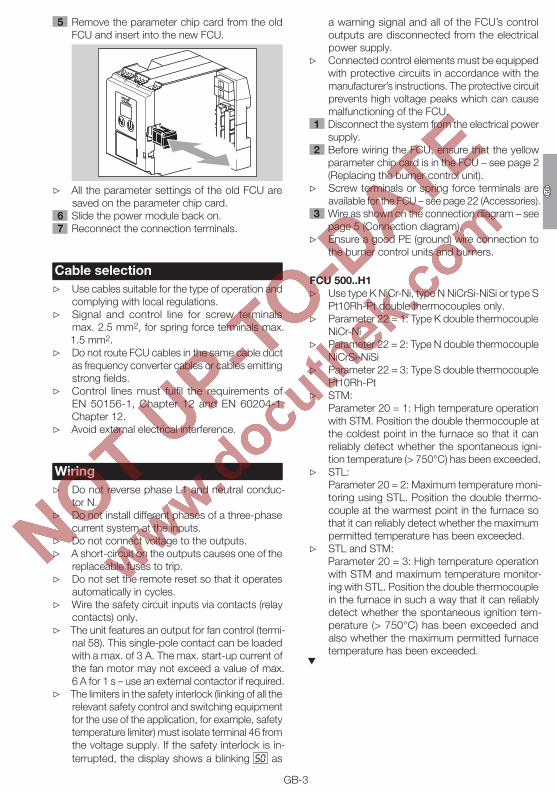
5 Remove the parameter chip card from the old FCU and insert into the new FCU.
▷ All the parameter settings of the old FCU are saved on the parameter chip card.
6 Slide the power module back on. 7 Reconnect the connection terminals.
Cable selection ▷ Use cables suitable for the type of operation and
complying with local regulations. ▷ Signal and control line for screw terminals
max. 2.5 mm2, for spring force terminals max. 1.5 mm2.
▷ Do not route FCU cables in the same cable duct as frequency converter cables or cables emitting strong fields.
▷ Control lines must fulfil the requirements of EN 50156-1, Chapter 12 and EN 60204-1, Chapter 12.
▷ Avoid external electrical interference.
Wiring ▷ Do not reverse phase L1 and neutral conduc-
tor N. ▷ Do not install different phases of a three-phase
current system at the inputs. ▷ Do not connect voltage to the outputs. ▷ A short-circuit on the outputs causes one of the
replaceable fuses to trip. ▷ Do not set the remote reset so that it operates
automatically in cycles. ▷ Wire the safety circuit inputs via contacts (relay
contacts) only. ▷ The unit features an output for fan control (termi-
nal 58). This single-pole contact can be loaded with a max. of 3 A. The max. start-up current of the fan motor may not exceed a value of max. 6 A for 1 s – use an external contactor if required.
▷ The limiters in the safety interlock (linking of all the relevant safety control and switching equipment for the use of the application, for example, safety temperature limiter) must isolate terminal 46 from the voltage supply. If the safety interlock is in-terrupted, the display shows a blinking 50 as
a warning signal and all of the FCU’s control outputs are disconnected from the electrical power supply.
▷ Connected control elements must be equipped with protective circuits in accordance with the manufacturer’s instructions. The protective circuit prevents high voltage peaks which can cause malfunctioning of the FCU.
Disconnect the system from the electrical power supply.
Before wiring the FCU, ensure that the yellow parameter chip card is in the FCU – see page 2 (Replacing the burner control unit).
▷ Screw terminals or spring force terminals are available for the FCU – see page 22 (Accessories).
Wire as shown on the connection diagram – see page 5 (Connection diagram).
▷ Ensure a good PE (ground) wire connection to the burner control units and burners.
FCU 500..H ▷ Use type K NiCr-Ni, type N NiCrSi-NiSi or type S
Pt10Rh-Pt double thermocouples only. ▷ Parameter 22 = 1: Type K double thermocouple
NiCr-Ni ▷ Parameter 22 = 2: Type N double thermocouple
NiCrSi-NiSi ▷ Parameter 22 = 3: Type S double thermocouple
Pt10Rh-Pt ▷ STM:
Parameter 20 = 1: High temperature operation with STM. Position the double thermocouple at the coldest point in the furnace so that it can reliably detect whether the spontaneous igni-tion temperature (> 750°C) has been exceeded.
▷ STL: Parameter 20 = 2: Maximum temperature moni-toring using STL. Position the double thermo-couple at the warmest point in the furnace so that it can reliably detect whether the maximum permitted temperature has been exceeded.
▷ STL and STM: Parameter 20 = 3: High temperature operation
with STM and maximum temperature monitor-ing with STL. Position the double thermocouple in the furnace in such a way that it can reliably detect whether the spontaneous ignition tem-perature (> 750°C) has been exceeded and also whether the maximum permitted furnace temperature has been exceeded.

GB-4
D GB F NL I E
FCU 500..C ▷ Parameter 51 = 1: Tightness test before furnace
start-up. ▷ Parameter 51 = 2: On; tightness test after fur-
nace shut-down, after a fault lock-out or after mains on.
▷ Parameter 51 = 3: On; tightness test before furnace start-up and after furnace shut-down.
▷ Parameter 51 = 4: Permanent via proof of closure function (POC).
Safety interlock output in the case of higher power requirement
▷ The burner start enable signal is issued to the connected burner control units via the safety interlock output (terminal 57).
▷ For units whose safety interlock input has a power consumption of ≤ 2 mA, the power (max. 0.5 A, cos ϕ = 1) of the FCU is sufficient to directly activate the burner control units.
▷ In the event that a higher output current is re-quired, the output current can be increased by means of a contact multiplier using two contac-tors. Design the circuit as follows:
61 62
FCU 500
3,15AT
5AT
FS
A STW/STB
+ - + -
L1
+24 V
V1V2
V3
41 42 44 45
65
46
66
47 48
68
53 54 55 56 57 5849 50 51 52
ϑLDS HTP
90°
0°
0°
90°
67
13 14 15 16 17 185 6 7 8 11 123 41 2
L1N
K1 K2k11k12
k21k22
F = IN × 0,6
Input (BCU)
+24 V DC

GB-5
D GB F NL I E
Connection diagram
FCU 500
▷ Legend – see page 20 (Legend).
Airm
inAir
Output
6162
FCU 500
3,15AT
5AT
FS
A
L1
+24 V
V1V2
V3
4142
4445
65
46
66
4748
68
5354
5556
5758
4950
5152
ϑ
N
0 V
0,6 x IN
pu2
14 pu
Gasmin
PZL
Gasmax
PZH
HT
LDS
HTP
90°0°
0°90°
PZLPZ
PDZ
34
+24 V DC
pu
PZ
k22
k12
K2K1
IN × 0,6
k11k21
M
P
67
1314
1516
1718
1112
34
12
STM/
STL+ -
+ -
56
78

61 62
FCU 500
3,15AT
5AT
FS
A
L1
+24 V
V1V2
V3
41 42 44 45
65
46
66
47 48
68
53 54 55 56 57 5849 50 51 52
ϑLDS HTP
90°
0°
0°
90°
67
13 14 15 16 17 1811 123 41 2
PE
L1N
3 2 116 67 4812 1115 13
S3 S4
S11 S10
0° 90°
M
IC 20
PE
S1S2
90°
0°
0°
90°
STW/STB
+ - + -
5 6 7 8
Output
GB-6
D GB F NL I E
IC 0 connected to FCU 500..F ▷ Parameter 40 = 1. The interface is tailored to the
requirements of the actuators IC 20, IC 20 E or IC 40 (operating mode 5).

61 62
FCU 500
3,15AT
5AT
FS
A
L1
+24 V
V1V2
V3
41 42 44 45
65
46
66
47 48
68
53 54 55 56 57 5849 50 51 52
ϑLDS HTP
90°
0°
0°
90°
67
13 14 15 16 17 1811 123 41 2
20 19 18 3 2 167 4812 11
S3 S4
S1 0
OUT 0°
90°
0°
90°
90°
0°
IC 20..E
S1S2
517 ++
IN OK
R R
PE
AD
AD
R
1 2 3 4 5 6
ON
µC
131516
M
PE
L1N
STW/STB
+ - + -
5 6 7 8
Output
GB-7
D GB F NL I E
IC 0 E connected to FCU 500..F ▷ Parameter 40 = 1. The interface is tailored to the
requirements of the actuators IC 20, IC 20 E or IC 40 (operating mode 5).

61 62
FCU 500
3,15AT
5AT
FS
A
L1
+24 V
V1V2
V3
41 42 44 45
65
46
66
47 48
68
53 54 55 56 57 5849 50 51 52
ϑLDS HTP
90°
0°
0°
90°
67
13 14 15 16 17 1811 123 41 2
IC 40
PE
19 18 16 15 14 12 11 10 8 7 5 4 2 1
A ACD DC
M
mA
LN
22 21 20
R..
STW/STB
+ - + -
5 6 7 8
Output
GB-8
D GB F NL I E
IC 40 connected to FCU 500..F ▷ Parameter 40 = 2. The interface is configured
according to the requirements of actuator IC 40. ▷ Set operating mode 27 on the IC 40 to ensure
perfect communication with the FCU.

61 62
FCU 5005AT
FS
A
L1
+24 V
V1V2
V3
41 42 44 45
65
46
66
47 48
68
53 54 55 56 57 5849 50 51 52
ϑLDS HTP
67
13 14 15 16 17 1811 123 41 2
NM
R B W
90°0°0°90°
L1
RBW
COM HI
LO
AUTO
STW/STB
+ - + -
5 6 7 8
Output
GB-9
D GB F NL I E
RBW valve connected to FCU 500..F ▷ Parameter 40 = 3. The interface is configured
according to the requirements of actuator RBW.
NM
+ F -
0°90°
L1
mAA DOUT+
-
RBW
SPS
61 62
FCU 5005AT
A
L1
+24 V
V1V2
V3
41 42 44 45
65
46
66
47 48
68
53 54 55 56 57 5849 50 51 52
ϑLDS HTP
67
13 14 15 16 17 1811 123 41 2
COM HI
LO
AUTO
STW/STB
+ - + -
5 6 7 8
NM
+ F -
0°90°
L1
mAA DOUT+
-
RBW
PLC
61 62
FCU 5005AT
A
L1
+24 V
V1V2
V3
41 42 44 45
65
46
66
47 48
68
53 54 55 56 57 5849 50 51 52
ϑLDS HTP
67
13 14 15 16 17 1811 123 41 2
COM HI
LO
AUTO
STW/STB
+ - + -
5 6 7 8

GB-10
D GB F NL I E
Frequency converter connected to FCU 500..FParameter 40 = 4: The interface is configured ac-cording to the requirements of a frequency converter.
61 62
FCU 5005AT
FS
A
L1
+24 V
V1V2
V3
41 42 44 45
65
46
66
47 48
68
53 54 55 56 57 5849 50 51 52
ϑLDS HTP
67
13 14 15 16 17 1811 123 41 2
mA
PZPDZ
M
L1
FU
DI 3DI 2DI 1P
0–100%
COM HI
LO
AUTO
SPS
Soll = Ist
STW/STB
+ - + -
5 6 7 8
Output
61 62
FCU 5005AT
FS
A
L1
+24 V
V1V2
V3
41 42 44 45
65
46
66
47 48
68
53 54 55 56 57 5849 50 51 52
ϑLDS HTP
67
13 14 15 16 17 1811 123 41 2
mA
PZPDZ
M
L1
FU
DI 3DI 2DI 1P
0–100%
COM HI
LO
AUTO
PLC
Target = actual
STW/STB
+ - + -
5 6 7 8

GB-11
D GB F NL I E
AdjustmentIn certain cases, it may be necessary to change the parameters set at the factory. Using the separate software package BCSoft and a PC opto-adapter, it is possible to modify parameters on the FCU, such as the pre-purge time or the behaviour in the event of a flame failure.
▷ The software package and the opto-adapter are available as accessories – see page 22 (Acces-sories).
▷ Changed parameters are saved on the integrated parameter chip card.
▷ The factory settings are secured with a program-mable password.
▷ If the password has been changed, the end cus-tomer can look up the changed password in the plant documentation or ask the system supplier.
Commissioning ▷ During operation, the 7-segment display shows
the program status: –– Unit off 00 Start-up position/standby H0 Waiting for switch-on delay or min. pause
time H1 Zone FCU waiting for purge signal from
furnace FCU H2 Waiting for start enable A0 Butterfly valve moves to closed position 0 Air monitor “no flow” state check 01 Fan run-up time tGV A1 Butterfly valve moves to open position 1 Air monitor operating position check P1 Pre-purge time tPV A2 Butterfly valve moves to ignition position Tightness test H7 Gas enable for inlet valves H8 Safety interlocks enable + waiting for burner
control unit operating signals 08 Operation/controller enable P9 Post-purge C1 C1 controlled air flow Remote control (with OCU) Programming mode X.X. High temperature mode 0.0. (blinking dots) Manual mode
WARNINGRisk of explosion! Check the system for tightness before commissioning.Do not start the FCU until the parameter settings and wiring are correct and the faultless processing of all input and output signals has been ensured.
Switch on the system. ▷ The display indicates –– .
Switch on the FCU by pressing the On/Off button. ▷ The display indicates 00 . ▷ If the display blinks (fault), reset the FCU by press-
ing the Reset/Information button. Apply the start-up signal to terminal 1.
▷ The display indicates H0 . The safety interlocks are scanned.
▷ The display indicates 01 . The fan starts. ▷ The display indicates 1 . Air flow monitoring
starts. ▷ The display indicates P1 . Pre-purge starts. ▷ FCU..C1: the tightness test runs in parallel to
pre-purge. If the tightness test lasts longer than pre-purge, the display indicates .

GB-12
D GB F NL I E
▷ The display indicates H7 . After pre-purge (and the end of the tightness test on FCU..C1), the valves in the gas inlet section are opened.
▷ The display indicates 08 . The FCU issues the enable signal to the burner control units to start the burners.
High temperature operationThe FCU 500..H1 is fitted with an integrated tem-perature module for high temperature operation. As soon as the FCU has received the signal from the connected double thermocouples that the tempera-ture defined in parameter 24 has been reached, a signal is sent to the high temperature inputs of the burner control units by the output at terminal 18. If voltage is applied to the high temperature inputs, the burner flames will no longer be monitored by the burner control units.
WARNINGRisk of explosion! High temperature operation is only permitted if the temperature in the furnace chamber is so high that the gas/air mixture is reli-ably combusted.In countries where EN 746/NFPA 86 is applicable, if the furnace wall temperature is greater than or equal to 750°C (1400°F), the flame may be moni-tored by a fail-safe temperature monitoring device that complies with the standard.Only if the temperature is greater than or equal to 750°C (1400°F) may voltage be applied to the high temperature inputs of the burner control units.Comply with the local safety regulations.
▷ In high temperature mode, the two dots in the display are lit permanently.
▷ The flame control system is placed out of op-eration.
▷ Once the furnace temperature falls below the value defined in parameter 24, terminal 18 is isolated from the voltage supply. The burner con-trol units continue operating with flame control, depending on their setting.
Manual mode ▷ For adjustment of the furnace system or for
fault-finding. ▷ In Manual mode, the FCU operates independ-
ently of the status of the inputs for start-up signal (terminal 1), controlled air flow (terminal 2) and remote reset (terminal 3). The function of the controller enable/emergency stop input (termi-nal 46) is retained.
▷ Manual mode is terminated by switching off the FCU or in the event of a power failure.
▷ Parameter 67 = 0: Manual mode unlimited in time. The furnace may continue to be operated manually in the event of failure of the control system or the bus.
▷ Parameter 67 = 1: The FCU will terminate Manual mode 5 minutes after the last time the Reset/Information button is pressed. It switches to the start-up position/standby (display 00 ).
Switch on the FCU while holding the Reset/In-formation button. Hold the Reset/Information button until the two dots in the display start to blink.
▷ If the Reset/Information button is pressed, the current step in Manual mode is shown. After the button has been held for 1 second, the next step will be shown. The FCU now executes its program sequence until the display indicates 08 .
FCU 500..F with IC 0 ▷ Following controller enable (display 0.8.), actuator
IC 20 can be opened and closed as required. Press the Reset/Information button.
▷ If the button continues to be held down, the actuator opens further until it reaches the open position.
▷ The display indicates A.1. with blinking dots. ▷ Once the button has been released, the butterfly
valve stops in the relevant position. Press the Reset/Information button again.
▷ If the button continues to be held down, the actuator closes further until it reaches the closed position.
▷ The display indicates A.0. with blinking dots. ▷ A change of direction takes place each time the
button is released and pressed again. When the butterfly valve has reached its final position, the dots disappear.
FCU 500..F with IC 40, FCU 500..F with RBW or frequency converter
▷ Following controller enable (status display 0.8. ), it is possible to move between open and close on a binary basis.

GB-13
D GB F NL I E
Assistance in the event of malfunction
DANGERElectric shocks can be fatal! Before working on possible live components, ensure the unit is discon-nected from the power supply.Fault-clearance must only be undertaken by author-ized, trained personnel.
▷ Faults may be cleared only using the measures described below.
▷ If the FCU does not respond even though all faults have been remedied: remove the unit and return it to the manufacturer for inspection.
? Faults ! Cause • Remedy
? The 7-segment display does not light up. ! Mains voltage is not applied. • Check the wiring, apply mains voltage (see type
label).
1 0 ? The display blinks and indicates 10 . ! Actuation of the remote reset input is faulty. ! Too many remote resets. It has been reset more
than 5 × within the last 15 minutes, either auto-matically or manually.
! Consecutive fault caused by a previous fault whose actual cause has not been remedied.
• Pay attention to previous error messages. • Remedy cause.
▷ The cause will not be remedied by performing a reset every time a fault lock-out occurs.
• Check whether remote reset complies with standards (EN 746 allows resetting only under supervision) and correct if necessary.
▷ The FCU may only be reset manually under su-pervision.
• Press the Reset/Information button on the FCU.
2 0 ? The display blinks and indicates 20 . ! Voltage is applied to the output at terminal 56. • Check the wiring and ensure that the voltage
outputs and inputs have the same polarity and are not reversed.
! The unit has suffered an internal fault in the power module.
• Replace the power module.
2 1 ? The display blinks and indicates 21 . ! Inputs 51 and 52 are activated simultaneously. • Check input 51.
▷ Input 51 may only be activated if the valve is open.
• Check input 52. ▷ Input 52 may only be activated if the valve is in
the ignition position.
2 2 ? The display blinks and indicates 22 . ! Valve IC 20 has been wired incorrectly. • Check the wiring. Wire the outputs and inputs
of connection terminals 52 – 55 as shown in the connection diagram – see page 6 (IC 20 con-nected to FCU 500..F1).
! The unit has suffered an internal fault in the power module.
• Replace the power module.
2 3 ? The display blinks and indicates 23 . ! The valve position is not constantly signalled
back to the FCU. • Check the wiring and ensure that the open/igni-
tion position of the valve is constantly signalled back via terminal 52.
3 0 ? The display blinks and indicates 30 . ! Abnormal data change in the parameters set for
the FCU. • Reset the parameters to their original values using
the BCSoft software. • Establish the cause of the fault to avoid repeat
faults. • Ensure that the cables have been installed prop-
erly – see page 3 (Cable selection). • If the measures described above do not help,
remove the unit and return it to the manufacturer for inspection.

GB-14
D GB F NL I E
3 1 ? The display blinks and indicates 31 . ! Abnormal data change in the parameters set for
the FCU. • Reset the parameters to their original values using
the BCSoft software. • Establish the cause of the fault to avoid repeat
faults. • Ensure that the cables have been installed prop-
erly – see page 3 (Cable selection). • If the measures described above do not help,
remove the unit and return it to the manufacturer for inspection.
3 2 ? The display blinks and indicates 32 . ! Supply voltage too low. • Operate the FCU in the specified mains voltage
range (mains voltage +10/-15%, 50/60 Hz). ! The unit has suffered an internal fault. • Remove the unit and return it to the manufacturer
for inspection.
3 3 ? The display blinks and indicates 33 . ! Faulty parameterization. • Check parameter settings using BCSoft. ! The unit has suffered an internal fault. • Remove the unit and return it to the manufacturer
for inspection.
3 6 ? The display blinks and indicates 36 . ! The unit has suffered an internal fault. • Remove the unit and return it to the manufacturer
for inspection.
3 7 ? The display blinks and indicates 37 . ! Faulty feedback from contact multiplier. • Check voltage supply to terminal 68 – see page 4
(Safety interlock output in the case of higher power requirement).
• Check the setting of parameter 73.
3 8
? The display blinks and indicates 38 . ! Interruption of signal at the “Fan feedback” input
(terminal 44). • Check voltage supply to terminal 44. • Check the setting of parameter 31.
4 0 ? The display blinks and indicates 40 . ! The gas solenoid valve V1 is leaking. • Check the gas solenoid valve V1. ! The gas pressure switch DGpu/2 (DGpu¾) for
the tightness test has been set incorrectly. • Check the inlet pressure. • Set DGpu/2 (DGpu¾) to the correct inlet pressure. • Check the wiring. ! The test pressure between V1 and V2 has not
decreased. • Check the installation. ! The test period is too long. • Change parameter 56 (Test period) using BCSoft. • If the fault cannot be remedied by doing this,
remove the unit and return it to the manufacturer for inspection.
4 1 ? The display blinks and indicates 41 . ! The gas solenoid valve V2 or V3 is leaking. • Check the gas solenoid valves V2/V3. ! The gas pressure switch DGpu/2 (DGpu¾) for
the tightness test has been set incorrectly. • Check the inlet pressure. • Set DGpu/2 (DGpu¾) to the correct inlet pressure. • Check the wiring. ! The test period is too long. • Change parameter 56 (Test period) using BCSoft. • If the fault cannot be remedied by doing this,
remove the unit and return it to the manufacturer for inspection.

GB-15
D GB F NL I E
4 2 ? The display blinks and indicates 42 . ! Test volume Vp2 is leaking. ! The gas solenoid valve V3, one of the burner-side
valves or the pipework is leaking. • Check the gas solenoid valves and pipework. ! The gas pressure switch DGpu/2 (DGpu¾) has
been set incorrectly. • Check the inlet pressure. • Set DGpu/2 (DGpu¾) to the correct inlet pressure. • Check voltage supply to terminal 45 (65). ! The set test period Vp1 + Vp2 is too long. • Change the test period using parameter 57. • If the fault cannot be remedied by doing this,
remove the unit and return it to the manufacturer for inspection.
4 4 ? The display blinks and indicates 44 . ! The FCU could not supply one of the test vol-
umes (Vp1 or Vp2). ! The FCU could not reduce the pressure of Vp1
or Vp2. • Faulty wiring of the activated valves. • Check valve actuation. • Faulty wiring of the pressure switches. • Check voltage supply to terminal 46 (65).
5 0 ? The display blinks and indicates 50 . ! Interruption of signal at the “Enable/Emergency
stop” input (terminal 46). • Check voltage supply to terminal 46. • Check the setting of parameter 10.
5 1 ? The display blinks and indicates 51 . ! Short-circuit on one of the outputs of the safety
circuit. • Check the wiring. • Check fine-wire fuse F1 (3.15 A, slow-acting, H).
▷ The fine-wire fuse can be replaced once the power module has been removed.
• Then check the faultless processing of all input and output signals.
! The unit has suffered an internal fault in the power module.
• Replace the power module.
5 2 ? The display blinks and indicates 52 . ! The FCU is being permanently reset. • Check voltage supply to terminal 2. • Apply voltage to terminal 2 only for reset, approx.
1 second.
6 0 ? The display blinks and indicates 60 . ! The safety temperature monitor (STM) has de-
tected an overtemperature condition. • Check the temperature control. • Check the wiring of terminals 5, 6, 7 and 8. ! The double thermocouple is defective. • Replace the double thermocouple. • If the fault cannot be remedied by doing this,
remove the FCU and return it to the manufacturer for inspection.
6 1 ? The display blinks and indicates 61. ! A malfunction has been detected in the thermo-
couple at terminals 5 and 6. • Check the wiring of terminals 5 and 6. • Replace the double thermocouple. • If the fault cannot be remedied by doing this,
remove the FCU and return it to the manufacturer for inspection.
6 2 ? The display blinks and indicates 62. ! A malfunction has been detected in the thermo-
couple at terminals 7 and 8. • Check the wiring of terminals 7 and 8. • Replace the double thermocouple. • If the fault cannot be remedied by doing this,
remove the FCU and return it to the manufacturer for inspection.

GB-16
D GB F NL I E
6 3 ? The display blinks and indicates 63. ! Temperature difference out of tolerance range. • Check the wiring of terminals 5, 6, 7 and 8. • Replace the double thermocouple. • If the fault cannot be remedied by doing this,
remove the FCU and return it to the manufacturer for inspection.
7 0 ? The display blinks and indicates 70 . ! The connected burner control units have not
signalled “Operating position reached (burner started)” within the time defined by parameter 47.
• Check voltage supply to “Operating signal” input (terminal 4).
• Check the setting of parameter 47.
7 2 ? The display blinks and indicates 72 . ! The connected burner control units are not ready
for operation. • Check voltage supply to terminal 67. • Check the setting of parameter 72.
8 9 9 4 9 5 9 6
9 7 9 8 9 9 ? The display indicates 89 , 94 , 95 , 96 , 97 , 98
or 99 . ! System fault – the FCU has performed a safety
shut-down. The cause may be a unit defect or abnormal EMC influence.
• Ensure that the ignition cable has been installed properly – see page 3 (Cable selection).
• Ensure that the EMC regulations for the system are satisfied – particularly for systems with fre-quency converters – see page 3 (Cable selection).
• Reset the unit. • Disconnect the protective system control from
the mains supply and then switch it on again. • Check mains voltage and frequency. • If the measures described above do not help, the
unit has probably suffered a hardware defect – remove the unit and return it to the manufacturer for inspection.
0 ? The display blinks and indicates 0 . ! The “no flow” state check of the air pressure
switch has failed. • Check the function of the air pressure switch.
Before the fan is switched on, there must be no high signal at the input for air monitoring (termi-nal 47) when air monitoring is activated.
1 ? The display blinks and indicates 1 . ! The operating check of the air pressure switch
has failed. The air monitor has not switched after fan start-up.
• Check the air monitor wiring. • Check the air pressure switch setpoint. • Check the function of the fan.
P ? The display blinks and indicates P . ! The input signal (terminal 48) for the air pressure
switch has dropped out during pre-purge. • Check the air supply during the purging process. • Check the electrical wiring of the air pressure
switch. • Check voltage supply to terminal 48. • Check the air pressure switch setpoint.
X ? The display blinks and indicates X . ! The input signal for the air pressure switch has
dropped out during start-up/operation at position step X.
! Failure of the air supply at position step X. • Check the air supply. • Check the air pressure switch setpoint.
X ? The display blinks and indicates X . ! The signal for monitoring the max. gas pressure
(terminal 50) has dropped out at position step X. • Check the wiring. • Check the gas pressure.

GB-17
D GB F NL I E
X ? The display blinks and indicates X . ! The signal for monitoring the min. gas pressure
(terminal 49) has dropped out at position step X. • Check the wiring. • Check the gas pressure.
A 0 ? The display blinks and indicates A 0 . ! No “Closed” signal from actuator. • Check the butterfly valve for air and the function
of the limit switches in the actuator. • Check the wiring. • Check the actuator. • If the fault cannot be remedied by doing this,
remove the unit and return it to the manufacturer for inspection.
A 1 ? The display blinks and indicates A 1 . ! No “Open” signal from actuator. • Check the butterfly valve for air and the function
of the limit switches in the actuator. • Check the wiring. • Check the actuator. • If the fault cannot be remedied by doing this,
remove the unit and return it to the manufacturer for inspection.
A 2 ? The display blinks and indicates A 2 . ! No “Ignition position” signal from actuator. • Check the butterfly valve for air and the function
of the limit switches in the actuator. • Check the wiring. • Check the actuator. • If the fault cannot be remedied by doing this,
remove the unit and return it to the manufacturer for inspection.
E ? The display blinks and indicates E . ! Internal communication with bus module has
suffered a fault. • Connected control elements must be equipped
with protective circuits in accordance with the manufacturer’s instructions.
▷ This prevents high voltage peaks which can cause malfunctioning of the FCU.
• Use suppressed electrode adapters (1 kΩ). • If the fault cannot be remedied by doing this,
remove the unit and return it to the manufacturer for inspection.
! The bus module is defective. • Replace the bus module.
? The display blinks and indicates . ! Incorrect or defective parameter chip card (PCC). • Only the parameter chip card provided is to be
used. • Replace defective parameter chip card.
1 ? The display blinks and indicates 1 . ! No input signal for the proof of closure switch
during standby. • Check the wiring.
▷ Mains voltage must be supplied to the FCU if the valve is closed and no voltage is to be applied if the valve is open.
• Check that the proof of closure switch and valve function perfectly, replace defective valves.
8 ? The display blinks and indicates 8 . ! The FCU is receiving no information as to whether
the POC switch contact is still open. • Check the wiring. • During start-up, mains voltage must be supplied
to the FCU if the valve is closed and no voltage is to be applied if the valve is open.
• Check that the proof of closure switch and valve function perfectly, replace defective valves.
GB-18
D GB F NL I E
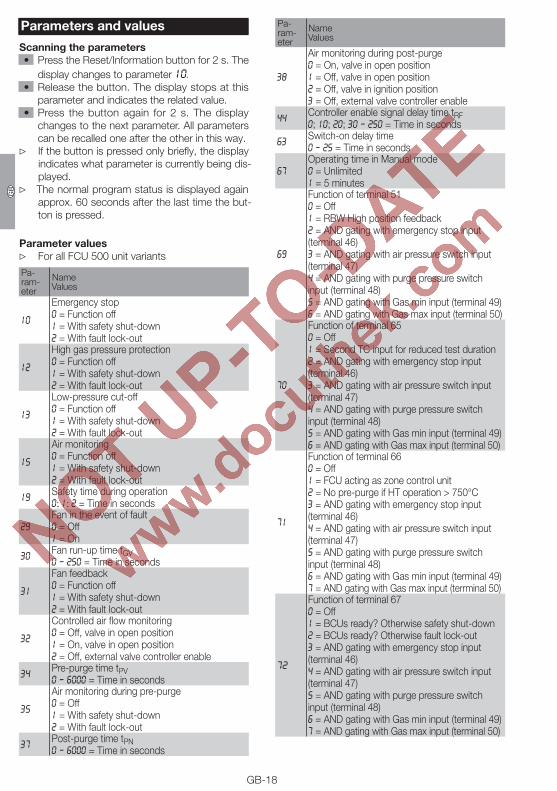
Parameters and values
Scanning the parameters • Press the Reset/Information button for 2 s. The
display changes to parameter 10. • Release the button. The display stops at this
parameter and indicates the related value. • Press the button again for 2 s. The display
changes to the next parameter. All parameters can be recalled one after the other in this way.
▷ If the button is pressed only briefly, the display indicates what parameter is currently being dis-played.
▷ The normal program status is displayed again approx. 60 seconds after the last time the but-ton is pressed.
Parameter values ▷ For all FCU 500 unit variants
Pa-ram-eter
Name Values
10
Emergency stop 0 = Function off 1 = With safety shut-down 2 = With fault lock-out
12
High gas pressure protection 0 = Function off 1 = With safety shut-down 2 = With fault lock-out
13
Low-pressure cut-off 0 = Function off 1 = With safety shut-down 2 = With fault lock-out
15
Air monitoring 0 = Function off 1 = With safety shut-down 2 = With fault lock-out
19 Safety time during operation 0; 1; 2 = Time in seconds
29Fan in the event of fault 0 = Off 1 = On
30 Fan run-up time tGV 0 – 250 = Time in seconds
31
Fan feedback 0 = Function off 1 = With safety shut-down 2 = With fault lock-out
32
Controlled air flow monitoring 0 = Off, valve in open position 1 = On, valve in open position 2 = Off, external valve controller enable
34 Pre-purge time tPV 0 – 6000 = Time in seconds
35
Air monitoring during pre-purge 0 = Off 1 = With safety shut-down 2 = With fault lock-out
37 Post-purge time tPN 0 – 6000 = Time in seconds
Pa-ram-eter
Name Values
38
Air monitoring during post-purge 0 = On, valve in open position 1 = Off, valve in open position 2 = Off, valve in ignition position 3 = Off, external valve controller enable
44 Controller enable signal delay time tRF 0; 10; 20; 30 – 250 = Time in seconds
63 Switch-on delay time 0 – 25 = Time in seconds
67Operating time in Manual mode 0 = Unlimited 1 = 5 minutes
69
Function of terminal 51 0 = Off 1 = RBW High position feedback 2 = AND gating with emergency stop input (terminal 46) 3 = AND gating with air pressure switch input (terminal 47) 4 = AND gating with purge pressure switch input (terminal 48) 5 = AND gating with Gas min input (terminal 49) 6 = AND gating with Gas max input (terminal 50)
70
Function of terminal 65 0 = Off 1 = Second TC input for reduced test duration 2 = AND gating with emergency stop input (terminal 46) 3 = AND gating with air pressure switch input (terminal 47) 4 = AND gating with purge pressure switch input (terminal 48) 5 = AND gating with Gas min input (terminal 49) 6 = AND gating with Gas max input (terminal 50)
71
Function of terminal 66 0 = Off 1 = FCU acting as zone control unit 2 = No pre-purge if HT operation > 750°C 3 = AND gating with emergency stop input (terminal 46) 4 = AND gating with air pressure switch input (terminal 47) 5 = AND gating with purge pressure switch input (terminal 48) 6 = AND gating with Gas min input (terminal 49) 7 = AND gating with Gas max input (terrminal 50)
72
Function of terminal 67 0 = Off 1 = BCUs ready? Otherwise safety shut-down 2 = BCUs ready? Otherwise fault lock-out 3 = AND gating with emergency stop input (terminal 46) 4 = AND gating with air pressure switch input (terminal 47) 5 = AND gating with purge pressure switch input (terminal 48) 6 = AND gating with Gas min input (terminal 49) 7 = AND gating with Gas max input (terminal 50)

GB-19
D GB F NL I E
Pa-ram-eter
Name Values
73
Function of terminal 68 0 = Off 1 = Coupling relay check 2 = AND gating with emergency stop input (terminal 46) 3 = AND gating with air pressure switch input (terminal 47) 4 = AND gating with purge pressure switch input (terminal 48) 5 = AND gating with Gas min input (terminal 49) 6 = AND gating with Gas max input (terminal 50)
77 Password 0000 – 9999
▷ Additional parameters for FCU 500..H1
Pa-ram-eter
Name Values
20
Temperature monitoring operating mode 0 = Function off 1 = STM function (high temperature operation) 2 = STL function 3 = STM and STL function
22
Thermocouple 1 = Type K 2 = Type N 3 = Type S
24 Safety temperature monitor limit value 650 – 1200 = Temperature in °C
25 Safety temperature limiter limit value 200 – 1600 = Temperature in °C
27Pre-purge during high temperature operation 0 = Off 1 = On
▷ Additional parameters for FCU 500..F1
Pa-ram-eter
Name Values
40
Air control 0 = Function off (FCU..F0) 1 = IC 20 2 = IC 40
45Minimum enable time 0 – 250 = Actuator in ignition position, waiting for enable signal, time in seconds
46Operating signal 0 = Controller enable off 1 = Controller enable on
▷ Additional parameters for FCU 500..F2
Pa-ram-eter
Name Values
40
Air control 0 = Function off (FCU..F0) 3 = RBW 4 = Frequency converter
41
Selection of RBW running time 0 = Off, High&Low position query 1 = Fixed running time for High&Low position 2 = Fixed running time for High position 3 = Fixed running time for Low position
42RBW running time 0 – 250 = Running time in seconds, if parameter 41 = 1, 2 or 3
45Minimum enable time 0 – 250 = Actuator in ignition position, waiting for enable signal, time in seconds
46Operating signal 0 = Controller enable off 1 = Controller enable on
▷ Additional parameters for FCU 500..C1
Pa-ram-eter
Name Values
51
Tightness control test instant 0 = Function off 1 = Before furnace start-up 2 = After furnace shut-down 3 = Before furnace start-up and after furnace shut-down 4 = Permanent via proof of closure function
53
Tightness control test volume 1 = Vp1 2 = Vp1, venting via relief valve 3 = Vp1 + Vp2, venting via relief valve
54Pressure reduction Vp2 0 = In standby 1 = Upon start-up
55Opening time relief valve V3 0 – 6000 = Venting time before Vp1 test in seconds
56
Test period Vp1 3 = Time in seconds 5 – 25 = (in 5 s steps) 30 – 3600 = (in 10 s steps)
57
Test period Vp1 + Vp2 3 = Time in seconds 5 – 25 = (in 5 s steps) 30 – 3600 = (in 10 s steps)
59Opening time V1 2 – 25 = Time for filling or pressure reduction in seconds
62 Minimum pause time 0 – 3600 = Time in seconds
65 Filling time before start-up 0 – 25 = Time in seconds
GB-20
D GB F NL I E
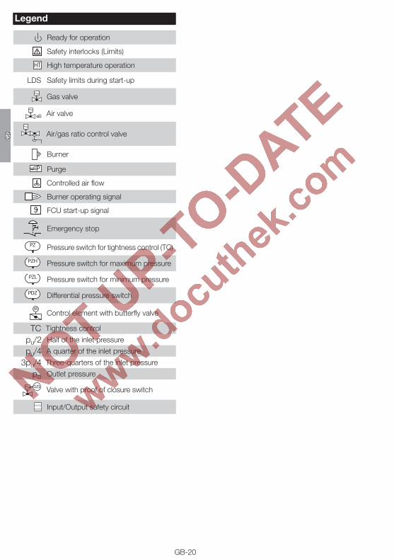
Legend
Ready for operation
Safety interlocks (Limits)
HT High temperature operation
LDS Safety limits during start-up
Gas valve
Air valve
Air/gas ratio control valve
Burner
P Purge
Controlled air flow
Burner operating signal
ϑ FCU start-up signal
Emergency stop
PZ Pressure switch for tightness control (TC)
PZH Pressure switch for maximum pressure
PZL Pressure switch for minimum pressure
PDZ Differential pressure switch
MControl element with butterfly valve
TC Tightness control
pu/2 Half of the inlet pressure
pu/4 A quarter of the inlet pressure
3pu/4 Three-quarters of the inlet pressure
pd Outlet pressure
GZL Valve with proof of closure switch
Input/Output safety circuit

GB-21
D GB F NL I E
Technical dataMains voltage: FCU 500Q: 120 V AC, -15/+10%, 50/60 Hz, ± 5%, FCU 500W: 230 V AC, -15/+10%, 50/60 Hz, ± 5%.Ambient temperature: -20 to +60°C (-4 to +140°F), no condensation permitted.Enclosure: IP 20 pursuant to IEC 529.Connection terminals: screw terminals: nominal cross-section 2.5 mm²,wire cross-section (rigid) min. 0.2 mm², wire cross-section (rigid) max. 2.5 mm²,wire cross-section AWG/kcmil min. 24, wire cross-section AWG/kcmil max. 12, 12 A. spring force terminals: nominal cross-section 2 x 1.5 mm², wire cross-section min. 0.2 mm², wire cross-section AWG min. 24, wire cross-section AWG max. 16,wire cross-section max. 1.5 mm²,rated current 10 A (8 A UL),to be observed in case of daisy chain.Contact rating: control outputs LDS (terminal 16), purge (termi-nal 17), HT (terminal 18), safety interlocks (termi-nal 57): max. 0.5 (1) A, cos ϕ = 1, gas valves V1 (terminal 13), V2 (terminal 14), V3 (terminal 15): max. 1 A, cos ϕ = 1, air valve (terminals 53, 54 and 55): max. 50 mA, cos ϕ = 1. The total current for the simultaneous activation of outputs V1, V2, V3, HT, purge, LDS, safety inter-locks and air valve must not exceed 2.5 A. 24 V DC signal for fault/operation: max. 0.1 A, fan: max. 3 A (start-up current: 6 A < 1 s).Number of operating cycles: FCU: 24 V DC signal for fault/operation: max. 10,000,000, On/Off button, Reset/Information button: 1000, power module: control outputs LDS (terminal 16), purge (terminal 17), HT (terminal 18), safety interlocks (terminal 57), gas valves V1 (terminal 13), V2 (terminal 14), V3 (terminal 15), air valve (terminals 53, 54 and 55), fan (terminal 58): max. 250,000.
Input voltage of signal inputs:Rated value 120 V AC 230 V ACSignal “1” 80 – 132 V 160 – 253 VSignal “0” 0 – 20 V 0 – 40 VInherent current:Signal “1” typ. < 2 mA
Rated value 24 V DCSignal “1” 24 V, ± 10%Signal “0” < 1 VInherent current:Signal “1” typ. 5 mA
Fuses, replaceable, F1: T 3.15A H, F2: T 5A H, pursuant to IEC 60127-2/5.Weight: 0.7 kg.

Elster GmbHPostfach 28 09, D-49018 OsnabrückStrotheweg 1, D-49504 Lotte (Büren)T +49 541 1214-0F +49 541 1214-370
GB-22
D GB F NL I E
Contact
If you have any technical questions, please contact your local branch office/agent. The addresses are available on the Internet or from Elster GmbH.
We reserve the right to make technical modifications in the interests of progress. [email protected], www.kromschroeder.com
Accessories
BCSoftThe current software can be downloaded from our Internet site at http://www.docuthek.com. To do so, you need to register in the DOCUTHEK.
Opto-adapter PCO 00Including BCSoft CD-ROM, Order No.: 74960625.
Bluetooth adapter PCO 00Including BCSoft CD-ROM, Order No.: 74960617.
Stickers for labelling
FCU 500Zone 2
For printing with laser printers, plotters or engraving machines, 27 × 18 mm or 28 × 17.5 mm.Colour: silver.
Connection terminal setFor wiring the FCU.
7492399774923998
7492399974924000
Plug-in, with screw terminal, for FCU..H0, Order No. 74923997, for FCU..H1, Order No. 74923998.Plug-in, with spring force terminal, 2 connection options per terminal, for FCU..H0, Order No. 74923999, for FCU..H1, Order No. 74924000.
Declaration of conformityThe FCU complies with the requirements of the fol-lowing Directives and Standards:– Low Voltage Directive (2006/95/EC)– Electromagnetic Compatibility Directive
(2004/108/EC)– EN 298– EN 1643– EN 60730– EN 61508, Parts 1 – 7 for Safety Integrity Level
SIL 3