Embed Size (px)
Citation preview

Chapter 6
WIRING SYSTEMS
Safe Electrical Design
CABLE SELECTION BASED ON CURRENT CARRYING CAPACITY REQUIREMENTS
Topic 6-3
INSTALLATION CONDITIONS
• Current carrying capacity (CCC) is the maximumcontinuous current that a particular cable can carrywithout overheating.
• Conditions which affect CCC, and thus the size ofcable conductor needed for a circuit, are: ambient temperature;
type of cable, ie ability of the insulation/sheathing totransmit heat
installation method

INSTALLATION CONDITIONS
• installation method examples are cables installed in:
air;
thermal insulation;
conduits, ducts and trunking
underground
INSTALLATION CONDITIONS • Table 3 of AS3008.1.1 2009 (Ref R-6-D) gives
guidance to installation methods• Table 3(1) unenclosed in air
• Table 3(2) Enclosed
• Table 3(3) buried direct in the ground
• Table 3(4) underground wiring enclosures
• In all tables in Ref R-6-D only the current carryingconductors are generally shown. (A & N for 1-phasecircuits and phase conductors for 3-phase circuits)
• .

INSTALLATION CONDITIONS • Single core cables can be configured;
Trefoil
Laid flat touching
Laid flat separated
• Separation between cables improves the heatdissipation of the conductors and improves currentcarrying performance.
• Laying the cables in trefoil reduces magnet effects.
0.5D

INSTALLATION CONDITIONS • It is important not to confuse separation between
conductors with cable supports systems that spacethe cable from surfaces such as walls and ceilings.
• If cables are installed so that they are in contact withcables of another circuit they are said to be grouped(see table 1 of Ref R-6-D )
• The CCC capacity of a cable will be affected by thepresence of certain external influences assummarised below.

INSTALLATION CONDITIONS
External influences: grouping of cables; ambient temperature; depth of laying different soil types for underground cables; varying loads thermal insulation direct sunlight. Harmonic currents Parallel cables. Electromagnetic interference.
INSTALLATION CONDITIONS
• Under such conditions the CCC given in Tables 4 to21 of Ref R-6-D must be corrected by the applicationof an appropriate rating factor or factors obtainedfrom Tables 22 to 29.

INSTALLATION CONDITIONS
• The circuit protection device selected to protect thecable will also affect the cable CCC as follows:
Circuit Breaker - 100% of current carrying capacity of cable(x 1).
H.R.C. fuse - 90% of current carrying capacity of cable (x0.9).
Semi-enclosed rewireable fuses (existing installationsonly) - 80% of current carrying capacity of cable (x 0.8).

INSTALLATION CONDITIONS • “Standard” conditions of installation and operation
to avoid de-rating are given by Ref R-6-D as;
CONDITION STANDARD
Ambient air temperature 40C
Ambient soil temperature 25C
Depth of laying cable underground 0.5m
Soil thermal resistivity 1.2C.m/W
Cable grouping single cable
Harmonic distortion See table 2 of Ref R-6-D
Circuit protection circuit breaker
INSTALLATION CONDITIONS
• Tables 2 and 22 to 29 of Ref R-6-D show the de-ratingfactors that must be applied to cables if they haveinstallation conditions that differ from “standard”.
• The de-rating factor for grouping of circuits is listed in thefinal column of each table for tables 3(1) to 3(4) asshown in figures F-6-3-1 and F-6-3-2

Fig PF-6-3-1 – Part Table 3(1) from AS/NZS 3008.1.1:2009

Fig PF-6-3-2 – Part Table 3(1) (Footnotes) from AS/NZS 3008.1.1:2009

INSTALLATION CONDITIONS
• Foot notes at the bottom tables 3(1) to 3(4) giveguidance to which de-rating table to use forinstallation conditions other than the grouping ofcables as shown in figure PF-6-3-1.
• Some examples of determining de-rating factorsfollow:

EXAMPLE Ex-6-3-1 Determining De-rating Factors
A single phase V75 T+E (Twin and Earth) cable installed on perforated cable tray in a factory with ambient air temperature of 55C.
Step 1: From tables 3(1) to 3(4) find appropriate installation method – in this case table 3(1) item 9
Step 2: As there is only one circuit no de-rating factor for grouping applies.
Step 3: From table 27(1), for a V75 cable at an ambient air temperature of 55C the de-rating factor is 0.72
EXAMPLE Ex-6-3-2 Determining De-rating Factors
A single phase V75 T+E (Twin and Earth) cable installed on perforated cable tray in a factory with ambient air temperature of 55C.
Step 1: From tables 3(1) to 3(4) find appropriate installation method – in this case table 3(4) item 4
Step 2: As there is only one circuit no de-rating factor for grouping applies.
Step 3: From table 27(2), for a V75 cable at a soil temperature of 35C the de-rating factor is 0.89
EXAMPLE Ex-6-3-3 Determining De-rating Factors
A single phase V75 T+E cable installed on perforated cable tray in a factory touching 3 other circuits.
Step 1: From tables 3(1) to 3(4) find appropriate installation method – in this case table 3(1) item 9
Step 2: From tables 3(1) item 9 column 6, read off the appropriate derating table in this case table 24.
Step 3: From table 24 item 13 column 8, the derating factor is 0.8

INSTALLATION CONDITIONS
Installation Conditions that Avoid De-Rating (Ref R-6-D Clause 3.5.2.2) • When cables are secured to supports such as ladder
or cable tray it is preferred to space the cables ofdifferent circuits from each other to allow thecirculation of air around the conductors.
• If cables must be grouped it is better to group cablesin small groups.

CURRENT CARRYING CAPACITY TABLES IN AS3008.1.1 2009 (Ref R-6-D)
Selecting Cable Size Based on Current Rating. • Selection of cable size based on current carrying
capacity is based on;
• IB ≤ IN ≤ IZ
• In words, this states that the rated CCC of aconductor (IZ) must be greater than or equal to thenominal current rating of the protective device (IN)which in turn must be greater than or equal to themaximum demand or expected load current of theconductor(IB)

CURRENT CARRYING CAPACITY TABLES IN AS3008.1.1 2009 (Ref R-6-D)
Selecting Cable Size Based on Current Rating (Cont’d)
• The steps involved in determining the minimum CCC (IZ) are:
1) determine the current requirements, maximum demand (IB) forthe circuit;
2) determine the current rating of the protective device (IN) to beused. Table 8.1, 8.2 and B1 of AS/NZS 3000:2007 shows standard protection device ratings up to 200A;
3) decide which cable type and installation method to use;
4) apply de-rating/rating factor from tables of Ref. R-6-D for theinstallation environment conditions where applicable;
CURRENT CARRYING CAPACITY TABLES IN AS3008.1.1 2009 (Ref R-6-D)
Selecting Cable Size Based on Current Rating (Cont’d)
5) Select a minimum conductor size for the look up current rating(or next largest) from tables of Ref. R-6-D. The actual currentrating of the cable under these conditions will be the currentrating from the table times de-rating factor/s. If there is morethan one de-rating factor the overall de-rating factor is theproduct of all de-rating factors that apply.
• The current carrying capacities for various types of commonly usedcables and installation methods are given in Tables 4 to 21 of Ref. R-6-D

CURRENT CARRYING CAPACITY TABLES IN AS3008.1.1 2009 (Ref R-6-D)
• The CCC of a cable may be reduced or increasedwhen particular external influences are present.
• In these cases a de-rating factor or rating factor mustbe applied before the correct minimum sizeconductor can be determined.
• Tables 22 to 29 of Ref. R-6-D provide de-rating/ratingfactors for various external influences.

CURRENT CARRYING CAPACITY TABLES IN AS3008.1.1 2009 (Ref R-6-D)
Which Table to Use. • Tables 4 to 15 of Ref. R-6-D are the most frequently
used CCC tables, covering the most commonly usedcables types and cable grouping arrangements.
• Tables 16 to 21 cover the more unusual cables suchas flexible, MIMS and aerial cables.
• Table 3 gives directions as to which of these tables touse for various cable configurations and installationmethods.

CURRENT CARRYING CAPACITY TABLES IN AS3008.1.1 2009 (Ref R-6-D)
How to use Table 3 (Cont’d)
1) Look up the Table 3 that applies to how the cable is to beinstalled. For example cable enclosed in conduit - Table 3(2)is appropriate.
2) In column 2 of Table 3(2) match a description of the cableconfiguration to be used against a reference drawing incolumn 3 that shows how the cable is to be installed. Forexample three single core cables installed in conduit in air.(See Fig PF-6-3-3)
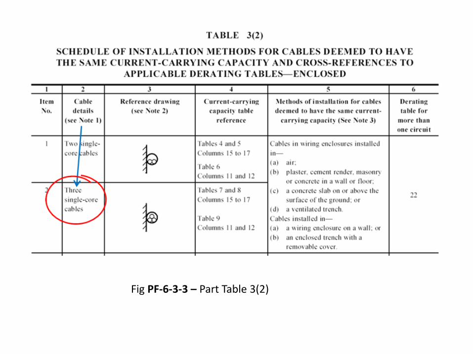
Fig PF-6-3-3 – Part Table 3(2)

CURRENT CARRYING CAPACITY TABLES IN AS3008.1.1 2009 (Ref R-6-D)
How to use Table 3 (Cont’d)
3) Column 4 on the same row gives the CCC tables and columnsto use to select the minimum conductor size. (See Fig PF-6-3-4)
4) If reference drawing in column 3 does not fully show how thecable is intended to be installed, then check column 5 for adescription of installation methods deemed to be the same.(See Fig PF-6-3-5)
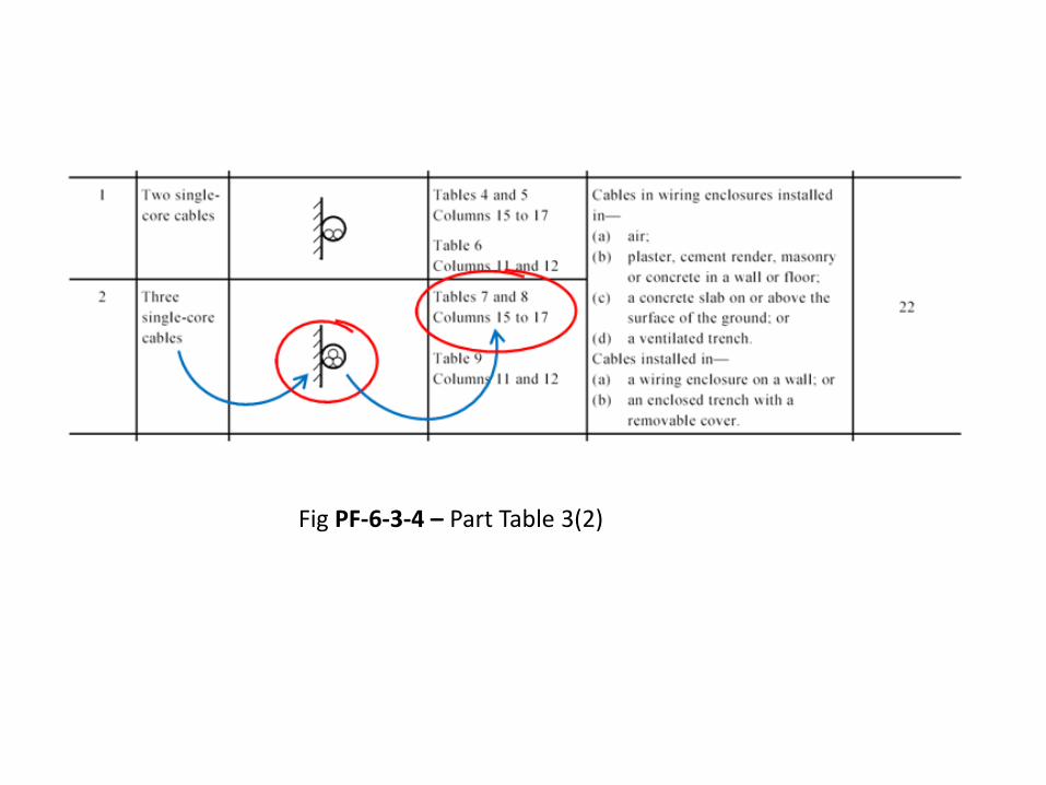
Fig PF-6-3-4 – Part Table 3(2)

Fig PF-6-3-5 – Part Table 3(2)
CURRENT CARRYING CAPACITY TABLES IN AS3008.1.1 2009 (Ref R-6-D)
How to use Table 3 (Cont’d)
3) When cables are to be installed with cables of othercircuits, a de-rating factor must be applied. Column6 gives the table to use to find the correct de-ratingfactor for groups of cables. For example a threecore cable installed unenclosed in air on cable traywith two other circuits – see Fig PF-6-3-6
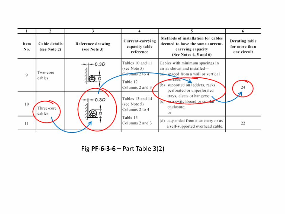
Fig PF-6-3-6 – Part Table 3(2)

CURRENT CARRYING CAPACITY TABLES IN AS3008.1.1 2009 (Ref R-6-D)
How De-Rating (and Rating) Factors are Applied.
• The rated CCC of a cable (IZ) when installed withcables of other circuits is decreased by a de-ratingfactor.
• The result can mean a larger cable is required for thecircuit.
• De-rating can be avoided by installing cables withminimum spacing as shown in Figure 1 of Ref. R-6-D.

CURRENT CARRYING CAPACITY TABLES IN AS3008.1.1 2009 (Ref R-6-D)
How De-Rating (and Rating) Factors are Applied (Cont’d)
• When using HRC fuses as the circuit protective device, ade-rating factor of 0.9 will automatically apply to the CCCof the cable.
• Rating factors (Tables 27 to 29) are applied to cables inambient temperatures (other than 40C air temperatureor 25C soil temperature) in the same way as de-ratingfactors.
• Rating tables are not given in the Table 3 schedule.

CURRENT CARRYING CAPACITY TABLES IN AS3008.1.1 2009 (Ref R-6-D)
Tables 4 to 21
• Table 3 of Ref. R-6-D can be used as an index to find whichtable from 4 to 14 has the equivalent CCC for that cableconfiguration and installation conditions.
• Tables 15 to 21 are not mentioned in table 3 as they apply toflexible cords, MIMS cables, aerial conductors etc. Whenselecting conductor size for these cables consult theappropriate table directly.
• De-rating and rating factor from the appropriate Tables 22 to29 must be applied where necessary.
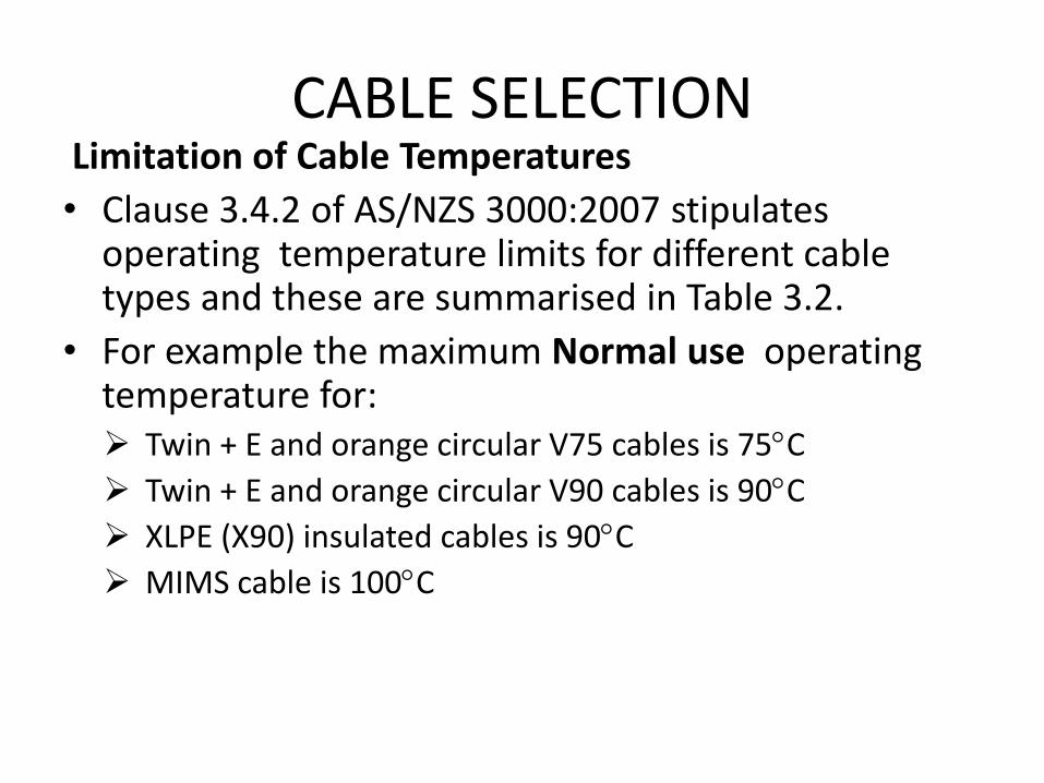
CABLE SELECTION Limitation of Cable Temperatures
• Clause 3.4.2 of AS/NZS 3000:2007 stipulatesoperating temperature limits for different cabletypes and these are summarised in Table 3.2.
• For example the maximum Normal use operatingtemperature for: Twin + E and orange circular V75 cables is 75C
Twin + E and orange circular V90 cables is 90C
XLPE (X90) insulated cables is 90C
MIMS cable is 100C

CABLE SELECTION
Conductors in Parallel
• Clause 3.4.3 of AS/NZS 3000:2007 providesguidelines on paralleling cables.
• CCCs for circuits comprising parallel multi-core cablesor groups of single-core cables may be determinedfrom the sum of the current-carrying capacity of thevarious cables connected in parallel provided that:
cables shall be not less than 4 mm2; and
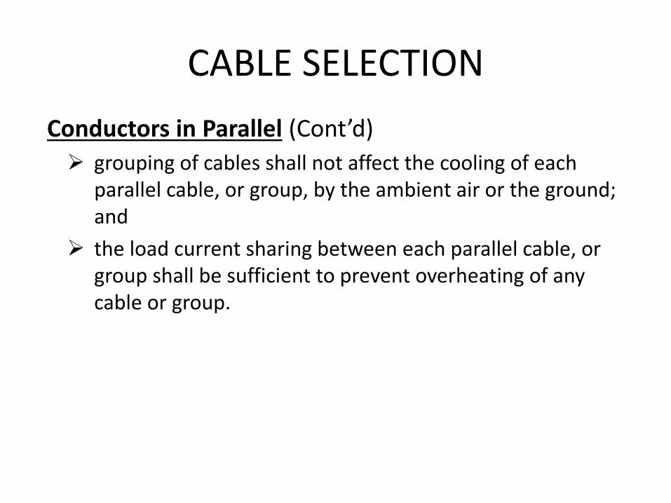
CABLE SELECTION
Conductors in Parallel (Cont’d)
grouping of cables shall not affect the cooling of eachparallel cable, or group, by the ambient air or the ground;and
the load current sharing between each parallel cable, orgroup shall be sufficient to prevent overheating of anycable or group.

EXAMPLE Ex-6-3-4 Conductors in Parallel
Determine the current carrying capacity of two sets of 70mm2 copper single core XLPE cables laid in trefoil on cable ladder. Each set is touching the other. Protection is by H.R.C. Fuse

Solution to EXAMPLE Ex-6-3-4 Conductors in Parallel
• CCC = 400A
• For detailed procedure in arriving at the aboveanswer see Workbook Chapter 6, Topic 6-3

CABLE SELECTION
Neutral Conductor Size
Clause 3.5.2 of AS/NZS 3000:2007 provides guidelines on neutral conductor size for various types of circuits and in summary states:
a. For 1-phase 2-wire circuit the neutral conductor orconductors must have a CCC not less thani. the CCC of the associated active conductor; or
ii. the total current to be carried, where there is more than one activeconductor

CABLE SELECTION Neutral Conductor Size (Cont’d) b. For multiphase circuit the CCC of the neutral conductor must
not be less than that determined in accordance with thefollowing:i. Where a circuit supplies a substantial load that generates harmonic
currents, e.g. fluorescent lighting, computers, soft starters, variablespeed devices or other electronic devices, the third and any higherorder harmonic current generated in the equipment shall be added tothe maximum out-of-balance load to determine the current to becarried by the neutral conductor
ii. The current carrying capacity of a circuit shall be not less than that ofthe current-carrying capacity of the largest associated activeconductor

CABLE SELECTION
Neutral Conductor Size (Cont’d)
c. The minimum size of a combined protective earth and neutral(PEN) conductor of consumers mains, or of a sub-main to anoutbuilding of an electrical installation forming a separateMEN installation in accordance with Clause 5.5.3.1, shall:i. comply with the requirements of Item (a) or Item (b) above, as
appropriate; and
ii. be not less than that of an earthing conductor as required by Clause5.3.3.

CABLE SELECTION
Protective Earthing Conductor Size • Size of protective earthing conductor is related to the
CSA of the largest active conductor and is selected fromTable 5.1 of AS/NZS 3000:2007. for example: 2.5 mm2 TPI copper active conductors enclosed in L.D. PVC
conduit is 2.5 mm2 (from Table 5.1) 10mm2 copper, 3 phase XLPE single core final sub-circuit
installed on cable tray is 4 mm2 (from Table 5.1). Sub-mains are 3 phase 95mm2 Aluminium XLPE single core
cables installed in underground enclosures is 16 mm2 (fromTable 5.1).
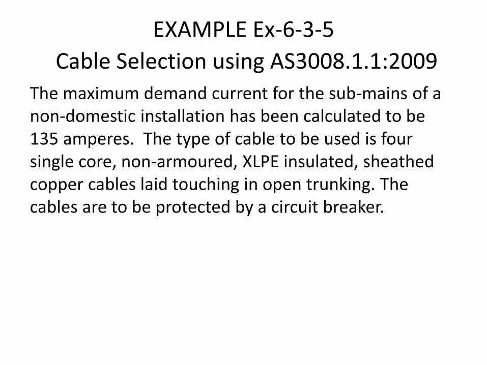
EXAMPLE Ex-6-3-5
Cable Selection using AS3008.1.1:2009
The maximum demand current for the sub-mains of a non-domestic installation has been calculated to be 135 amperes. The type of cable to be used is four single core, non-armoured, XLPE insulated, sheathed copper cables laid touching in open trunking. The cables are to be protected by a circuit breaker.

Solution to EXAMPLE Ex-6-3-4 Conductors in Parallel
• Cable Size is 50mm2 ( 176A )
• Protective Earth Size is 16mm2
• For detailed procedure in arriving at the aboveanswer see Workbook Chapter 6, Topic 6-3

CABLE SELECTION
Adjustable Circuit Breakers (200A - 400A)
• When a circuit requires a protection device largerthan 200A an adjustable circuit breaker (Figure F-6-3-7) may be used to match the setting of the breaker tothe capacity of the cable.
• This way no capacity between the preset size of the
breaker and the cable is lost.

CABLE SELECTION BASED ON VOLTAGE DROP REQUIREMENTS
Topic 6-4

INTRODUCTION
• Electrical cables made from either copper (Cu) orAluminium (Al) have resistance.
• When an electric current flows in those conductors avoltage drop (VD) across the length of the cable willoccur.
• This VD will reduce the supply voltage available atthe terminals of the load supplied by the cables.

INTRODUCTION • Clause 3.6.2 of AS/NZS 3000:2000 states “The CSA of
every current-carrying conductor shall be such thatthe VD between the point of supply for the lowvoltage electrical installation and any point in thatelectrical installation does not exceed 5% of thenominal voltage at the point of supply”.
• This means that for a 400/230 V system the voltagemay drop to 380/218.5 and still comply withAustralian Standards

INTRODUCTION • Excessive VD drop in an installation may cause: a reduction in the effective operation of appliances and
lighting;
overloading of cables if a fault occurs by delaying theoperating time of circuit protection devices;
over-heating of motors, noticeable when the voltagereduction is more than 5%.
• The effect of VD must be considered when selectingcables, especially for circuits which have long routelengths and circuits with relatively high currents.

INTRODUCTION
• Voltage drop (V) in the cables of a circuit is caused bythe current in the circuits (I) and the resistance (R) ofthe circuit
• VDROP = I x Rcable
• Factors that determine the voltage drop in a cableare the; Length of the cable.
CSA of the cable.
Current flowing in the cable.
Type of material of the cable (copper or aluminium).

INTRODUCTION
Operating temperature of the cable and ability to dissipateheat.
Installation method of the cable (trefoil, laid flat or in amulti-core cable).
• The voltage drop on any given combination of theabove can be predicted before the cable is selectedand installed by using tables 40 to 51 of Section 4 ofRef. R-6-D (AS3008.1.1-2009).

VOLTAGE DROP TABLES IN AS3008.1.1 (2009)
• Tables 40 to 51 of Ref. R-6-D show values of Vc inMillivolts per Ampere Metre for a number of copperand aluminium cable configurations at varioustemperatures.
• All of the values listed in tables 40 to 51 are 3 phasevalues of Vc.
• When performing a voltage drop calculation thevalue of Vc is obtained directly from the tables.
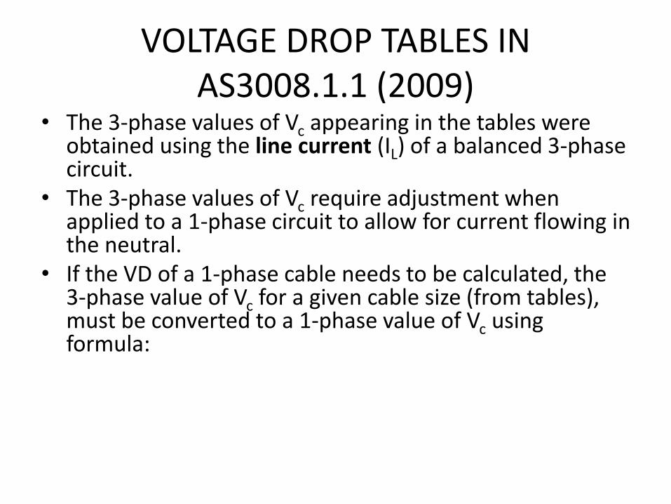
VOLTAGE DROP TABLES IN AS3008.1.1 (2009)
• The 3-phase values of Vc appearing in the tables wereobtained using the line current (IL) of a balanced 3-phasecircuit.
• The 3-phase values of Vc require adjustment whenapplied to a 1-phase circuit to allow for current flowing inthe neutral.
• If the VD of a 1-phase cable needs to be calculated, the3-phase value of Vc for a given cable size (from tables),must be converted to a 1-phase value of Vc using formula:

VOLTAGE DROP TABLES IN AS3008.1.1 (2009)
• When the single phase value of Vc has beencalculated, the 1-phase value of Vc must beconverted to a 3-phase value of Vc. using :
• The CSA of a suitable cable is then found from atable;
drop voltage phase three3
2drop voltage phase single
drop voltage phase single2
3 drop voltage phase three

VOLTAGE DROP TABLES IN AS3008.1.1 (2009)
• A characteristic of a 3-phase circuit is that it haslower ‘losses’ than a single phase circuit of the samematerial, length and CSA.
• The 3-phase Vc for an equivalent conductor is alwayssmaller than the Vc of single phase circuit.

VOLTAGE DROP CALCULATIONS USING AS3008.1.1 (2009)
• To determine the actual voltage drop for a givencable size, use the equation:
• where
• Vd = the actual voltage drop, in volts
• Vc = the value found from Ref. R-6-D tables in mV/A.m
• L = the route length of circuit, in metres
• I = the current to be carried by the cable, in amperes.
1000
ILV Vor
IL
1000VV c
dd
c
VOLTAGE DROP CALCULATIONS USING AS3008.1.1 (2009)
• To find the total voltage drop for an entireinstallation the voltage drops of the consumer’smains and final sub-circuits are added together.

EXAMPLE Ex-6-4-1 Calculating Vd
Calculate the voltage drop for the installation
Main Switch
BoardConsumers Mains
Load
Final Sub-circuit
Point of supply
16 mm2 XLPE Cu S.D.I.
M.D. = 63 A, L = 35m
4 mm2 V90 Cu 4 C+E.
M.D. = 25 A, L = 50m

Solution to EXAMPLE Ex-6-4-1 Calculating Vd
For consumers mains:
For final sub-circuit:
Total voltage drop is 5.62 + 12.75 = 18.37V
• For detailed procedure in arriving at the aboveanswer see Workbook Chapter 6, Topic 6-4
V62.51000
3555.
1000
632ILV V c
d
V75.121000
25502.10
1000
ILV V c
d

VOLTAGE DROP CALCULATIONS USING AS3008.1.1 (2009)
Single Phase Installations
• When an installation contains single phase circuitsthe values of Vc must be converted to single phasevalues and then used in the voltage drop equation.

VOLTAGE DROP CALCULATIONS USING AS3008.1.1 (2009)
Three Phase Installations with Single Phase Circuits
• If an installation is supplied by 3-phase and has 1-phase circuits within the installation, both 3 and 1phase VDs must be converted to a common unitvalue so they can be added together.
• Both values can be converted to a percentage oftheir nominal value, or the 3-phase Vd may beconverted to a single phase Vd, by dividing it by √3, inthe same way a line voltage (VL) of 400V is convertedto a phase voltage (VP) of 230V.

CABLE SELECTION BASED ON VOLTAGE DROP
• Cable sizes are selected in order not to exceed a certainVD drop figure.
• Thus the following equation (as presented in previousTopic) is used to determine Vc and then Tables 40 to 51 ofRef R-6-D are consulted to select appropriate cable size
IL
1000VV d
c

EXAMPLE Ex-6-4-2
Cable Selection Based on Voltage Drop
For the installation below:
a) Calculate the maximum permissible voltage drop (VP) forthe f.s.c.
b) Calculate the maximum permissible value of Vc
c) Determine the minimum cable size
Main Switch
BoardConsumers Mains
Load
Final Sub-circuit
Point of supply
Vd = 12V V90 Cu 4 C+E.
M.D. = 32 A, L = 30m

Solution to EXAMPLE Ex-6-4-2
Cable Selection Based on Voltage Drop a) FSC allowable volt drop is 8V
b) maximum permissible value of Vc is 8.333 mV/A.m
c) minimum cable size is 6 mm2
• For detailed procedure in arriving at the aboveanswer see Workbook Chapter 6, Topic 6-4

EXAMPLE Ex-6-4-3 MAXIMUM LENGTH OF CABLE BASED ON VD
Calculate the maximum length of a 3 phase 2.5mm2 V75 multicore copper cable protected by a 20A C.B, if the permissible voltage drop is 12V.
• Solution: Vc, from Table 42 is 15.6mV/A.m
• Then fromIL
1000V V d
c
m11000
IV
1000VL
c
d 46.38206.15
2

CABLE SELECTION BASED ON EARTH FAULT LOOP IMPEDANCE REQUIREMENTS
Topic 6-5

INTRODUCTION
• VD limits the maximum length of conductors whencurrent is flowing under normal operating conditionsi.e. from phase to phase or phase to neutral.
• Earth fault loop impedance limits the maximumlength of conductors when current is flowing underearth fault conditions i.e. from phase to earth.
• The protective earthing (PE) conductor is usuallysmaller than the active or neutral conductors; itsimpedance will be higher than that of the active orneutral conductors.

INTRODUCTION
• Under earth fault conditions the combinedimpedance of the fault path from active to PEconductor will be higher than the impedance of afault path from active to active, or active to neutral.
• In long cable runs because of the higher impedancefrom active to PE conductor the fault current will belower than that of a fault on a cable of a shorterlength.
• The lower the earth fault current, the longer thecircuit protection device will take to operate.

INTRODUCTION
• In the time that it takes to operate the circuitprotection device a touch voltage will be present onthe exposed conductive parts of the apparatus underfault.
• If a person is in simultaneous contact with theexposed conductive part and earth they are said tobe in “indirect contact with live parts”.
• AS/NZS 3000:2007 requires fault protection(protection from indirect contact with live parts).

INTRODUCTION • The most commonly used method for providing this
protection is automatic disconnection of supply.
• Automatic disconnection of the supply (AS/NZS3000:2007) shall be achieved by:-
provision of a system of earthing in which exposedconductive parts are connected to protective earthingconductors, and;
automatic disconnection of the fault by an over-currentprotective device or an RCD within the disconnection time.

INTRODUCTION
• Each circuit in an electrical installation is to be protectedsuch that automatic disconnection of supply will occurwithin the specified disconnection time when a fault ofnegligible impedance occurs between an activeconductor and a PE conductor or an exposed conductivepart anywhere in the electrical installation.
• This condition is met when the impedance of the pathtaken by the fault current, known as the earth fault-loop,is low enough to allow sufficient current to flow to causethe protective device to operate within the specifiedtime.
INTRODUCTION
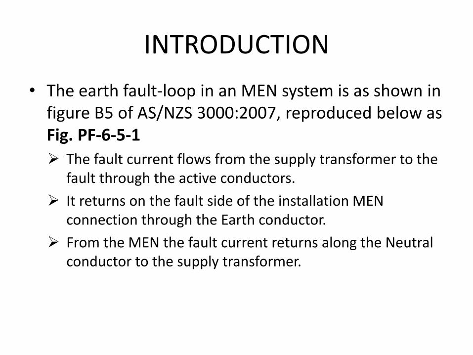
• The earth fault-loop in an MEN system is as shown infigure B5 of AS/NZS 3000:2007, reproduced below asFig. PF-6-5-1
The fault current flows from the supply transformer to thefault through the active conductors.
It returns on the fault side of the installation MENconnection through the Earth conductor.
From the MEN the fault current returns along the Neutralconductor to the supply transformer.

Figure F-6-5-1 Reproduction from Figure B5 of AS/NZS 3000:2007

CABLE IMPEDANCE TABLES IN AS/NZS 3008.1.1
• The total earth fault loop impedance is the sum ofthe supply transformer impedance and theimpedance of all cables in the path between thesupply and the fault.
• For cable ratings up to 400A, the reactance can beignored and calculations are done using only the A.C.resistance.
• Larger cables should take reactance into account.

CABLE IMPEDANCE TABLES IN AS/NZS 3008.1.1
• The A.C. resistance of conductors in any givencombination of cables can be predicted before the cableis selected and installed by using tables 34 to 39 ofSection 4 of Ref-R-6-D.
• The unit values in tables 34 to 39 of Ref-R-6-D are givenin Ohms per kilometre (Ω/km). To calculate the A.C.resistance of a given conductor use the equation;
1000
LRR C

CABLE IMPEDANCE TABLES IN AS/NZS 3008.1.1
where
R = the resistance of the cable in Ohms (Ω)
RC = the table value in ohms per km (Ω/km)
L = the length of the conductor in meters (m)
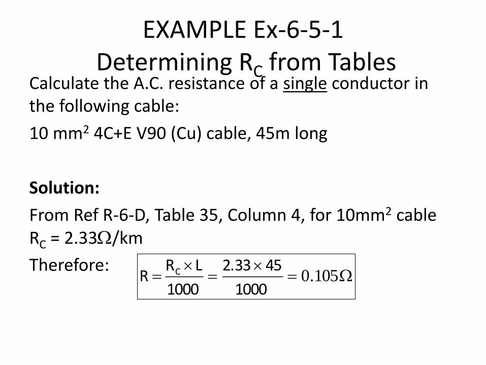
EXAMPLE Ex-6-5-1 Determining RC from Tables
Calculate the A.C. resistance of a single conductor in the following cable:
10 mm2 4C+E V90 (Cu) cable, 45m long
Solution:
From Ref R-6-D, Table 35, Column 4, for 10mm2 cable RC = 2.33/km
Therefore:
105.0
1000
452.33
1000
LR R C

EARTH LOOP IMPEDANCE CALCULATIONS
• Any circuit protected by an RCD satisfies therequirements of earth fault loop impedance.
• RCDs that protect light and power circuits must havea rated residual current of not greater than 30mA(AS/NZS 3000:2007 section 2.6.3).
• Calculation of earth fault loop impedance to thesecircuits is pointless.
• The low current (< 30mA) and extremely fastoperation (< 300mS) ensure automatic disconnectionof supply within the required time.
EARTH LOOP IMPEDANCE CALCULATIONS
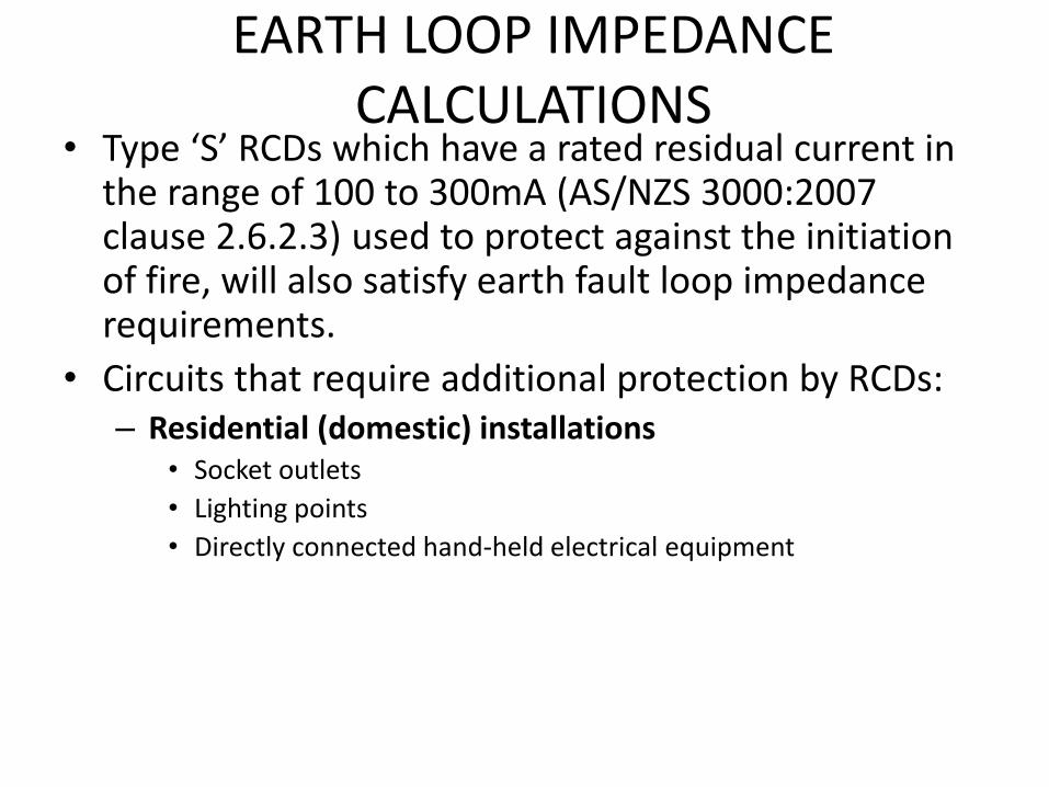
• Type ‘S’ RCDs which have a rated residual current inthe range of 100 to 300mA (AS/NZS 3000:2007clause 2.6.2.3) used to protect against the initiationof fire, will also satisfy earth fault loop impedancerequirements.
• Circuits that require additional protection by RCDs:– Residential (domestic) installations
• Socket outlets
• Lighting points
• Directly connected hand-held electrical equipment

EARTH LOOP IMPEDANCE CALCULATIONS
– Other electrical (non-domestic) installations• Socket-outlets not exceeding 20A.
• Lighting circuits not exceeding 20 A.
• Final sub-circuits supplying directly connected hand-held electricalequipment, e.g. hair dryers or tools.
• Circuits that are not RCD protected, to which earthfault loop impedance should be applied, include:
– Socket outlets exceeding 20A.
– Fixed or stationary (mass exceeds 18 kg) equipment
– Sub-mains

DISCONNECTION TIMES
• When an earth fault occurs a touch voltage appearson exposed conductive parts.
• This touch voltage will be disconnected quickly if theearth fault loop impedance is low enough to ensure alarge current flow occurs to operate the circuitprotection.
• This is done in miniature circuit breakers (MCBs) bythe magnetic trip mechanism.
• If the fault current is too low the circuit breaker willtrip by the thermal mechanism.

DISCONNECTION TIMES
• The longer time a person is in contact with a touchvoltage the greater the risk of injury to the person.
• Clauses 1.5.5.3(d) and 5.7.2 of AS/NZS 3000:2007specify time in which automatic disconnection ofsupply must occur.

DISCONNECTION TIMES The maximum disconnection time for 230/400 V supply voltage shall not exceed the following:
i. 0.4 s for final sub-circuits that supply:A. socket-outlets having rated currents not exceeding
63 A; or
B. hand-held Class I equipment; or
C. portable equipment intended for manual movementduring use.
ii. 5 s for other circuits including sub-mains and finalsub-circuits supplying fixed or stationary equipment.

DISCONNECTION TIMES • The total earth fault loop impedance (ZS) is
calculated by: (AS/NZS 3000:2007 section B4.5);
aI Z 0U
s
Where: Zs = the total earth fault loop impedance in Ohms (Ω) U0 = the nominal phase voltage in volts (V) Ia = current causing automatic operation of the
protective device in amperes (A) as follows:
Type B circuit breaker Ia = 4 x rated current of circuit breaker Type C circuit breaker Ia = 7.5 x rated current of circuit breaker Type D circuit breaker Ia = 12.5 x rated current of circuit breaker

DISCONNECTION TIMES
Figure PF-6-5-2 shows typical tripping curves for type C and D miniature circuit breakers. Type C circuit breakers are for general use (most common) and type D circuit breakers are used for motor protection. From Figure PF-6-5-2 it can be seen that: To obtain a trip time of 0.4s for a C type circuit breaker requires a
fault current of 7.5 times the circuit breaker rating To obtain a trip time of 0.4s for a D type circuit breaker requires a
fault current of 12.5 times the circuit breaker rating To obtain a trip time of 5.0s for either type of circuit breaker
requires a fault current of 4.0 times the circuit breaker rating
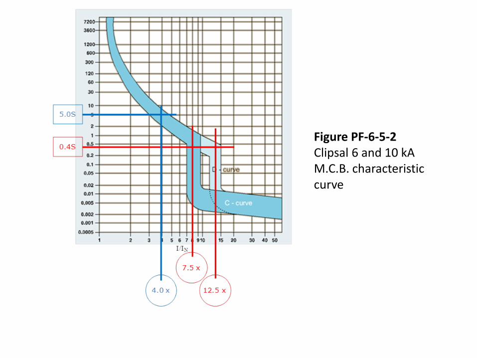
Figure PF-6-5-2 Clipsal 6 and 10 kA M.C.B. characteristic curve
DISCONNECTION TIMES
• When designing circuits for a 5 s disconnection time,the circuit protection manufacturer’s data must beused.
• Calculations and table data in AS/NZS 3000:2007refers to a 0.4 second disconnection time.
• The value of 4 x in figure PF-6-5-2 is the currentrequired to operate the circuit breaker within 5 s.
• This is not be confused with a type ‘B’ circuit breakerwhich will operate in 0.4 seconds if 4 times its ratedcurrent passes through it..

EXAMPLE Ex-6-5-2 Calculating Zs (Total earth fault loop impedance)
Calculate the maximum permissible earth fault loop impedance (ZS) of a circuit supplying a 32A three phase socket outlet that is protected by a type ‘C’ 32A M.C.B. in a 230/400 volt installation.
Solution:
958.0325.7
2300
aI ZU
s

TOTAL EARTH FAULT LOOP IMPEDANCE (ZS)
• The maximum value of total earth fault loopimpedance (ZS) can also be found using table 8.1 ofAS/NZS 3000:2007.
• Only 0.4 second disconnection times are shown forcircuit breakers.
• If an earth fault loop impedance is required for afixed or stationary appliance with a 5 seconddisconnection time it will have to be calculated.

EXAMPLE Ex-6-5-3 Determining Earth Fault Impedance from Tables Determine the total earth fault loop impedance for the following:
• A 25A socket outlet in data room protected by a 25Atype C circuit breaker
Solution:
• From Clause 1.5.5.3(d) of AS/NZS 3000:2007 SocketOutlet is less than 63A, therefore 0.4s disconnecttime applies
• From table 8.1 of AS/NZS 3000:2007, Zs = 1.23

INTERNAL EARTH FAULT LOOP IMPEDANCE (Zint)
• The total earth fault loop impedance is made up oftwo parts, the External and Internal earth fault loopimpedances (see figure PF-6-5-1).
• In the vast majority of cases the impedance of theexternal section will be unknown.
• To simplify calculations it is assumed that at thecircuit protection device (reference point) as shownin figure PF-6-5-1, that at least 80% of the nominalsupply voltage (230V) is available under earth faultconditions.
INTERNAL EARTH FAULT LOOP IMPEDANCE (Zint)
• When calculating the internal earth fault loopimpedance 80% of the nominal supply voltage isused.
• If a larger value of voltage is present, a higher earthfault current will flow. The operating time of theprotection device will be shorter and disconnect thecircuit automatically in less time than is required.
• The internal earth fault loop impedance (Zint) iscalculated from: (AS/NZS 3000:2007 section B5.2.1);

INTERNAL EARTH FAULT LOOP IMPEDANCE (Zint)
a
0int
I
0.8U Z
Where: Zint = internal earth fault loop impedance in Ohms (Ω) U0 = the nominal phase voltage in volts (V) Ia = current causing automatic operation of the
protective device in amperes (A) as follows:
Type B circuit breaker Ia = 4 x rated current of circuit breaker Type C circuit breaker Ia = 7.5 x rated current of circuit breaker Type D circuit breaker Ia = 12.5 x rated current of circuit breaker
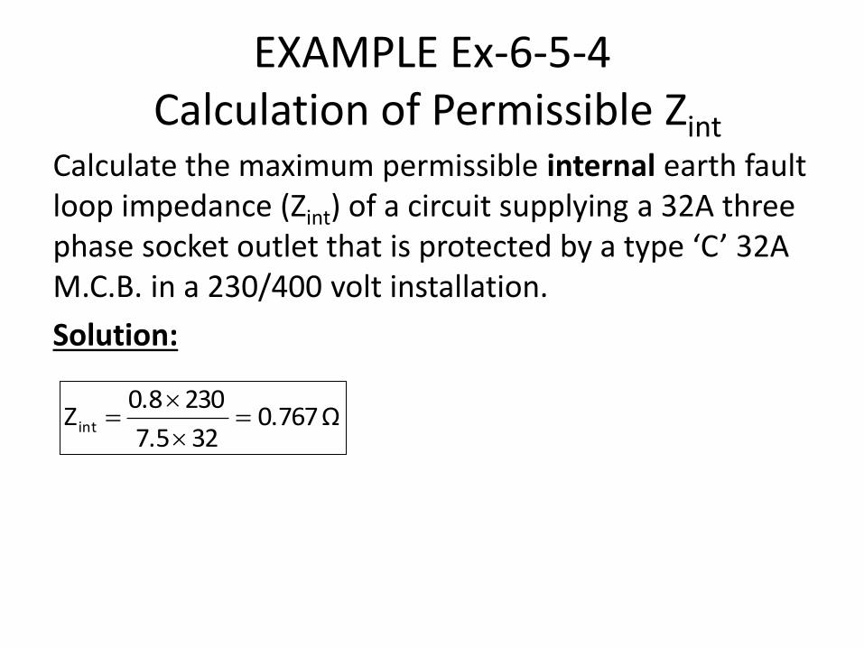
EXAMPLE Ex-6-5-4 Calculation of Permissible Zint
Calculate the maximum permissible internal earth fault loop impedance (Zint) of a circuit supplying a 32A three phase socket outlet that is protected by a type ‘C’ 32A M.C.B. in a 230/400 volt installation.
Solution:
0.767Ω327.5
2300.8Z int

INTERNAL EARTH FAULT LOOP IMPEDANCE (Zint)
• Once the maximum permissible internal earth loopimpedance is known, the maximum length of thecable can be determined so that the impedance ofthe cable is less than or equal to the maximumpermissible internal earth fault impedance.

CABLE SELECTION BASED ON EARTH LOOP IMPEDANCE
• The major impact that earth fault loop impedance has ona circuit is to limit its length for a given CSA.
• Tables 34 to 39 of Ref R-6-D can be used to predict theearth fault loop impedance of a cable.
• In most cases if the cable has been selected correctlybased on CCC and VD the earth fault loop impedance willnot be an issue.
• Normally VD is the most significant factor that limits thelength of a cable. Long cables which are lightly loadedhowever can be an issue.

EXAMPLE Ex-6-5-5 EARTH FAULT LOOP IMPEDANCE
a) Calculate the maximum permissible earth fault loopimpedance (Zint) of a circuit supplying a hot waterservice protected by a type ‘C’ 20A M.C.B. in a 230/400volt installation.
b) If this circuit is wired in 2.5 mm2 2C+E V90 orangecircular cable and the length of the cable run is 60m...i. Determine the impedance of the cable between active
and protective earthing conductors
ii. Does the circuit comply with AS 3000 requirement forearth fault loop impedance (Y/N) and why?
iii. Calculate the voltage drop on this section of cable.
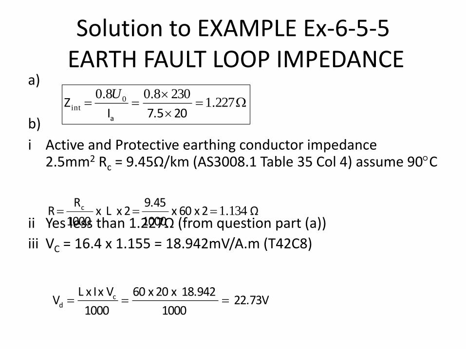
Solution to EXAMPLE Ex-6-5-5 EARTH FAULT LOOP IMPEDANCE
a)
b) i Active and Protective earthing conductor impedance
2.5mm2 Rc = 9.45Ω/km (AS3008.1 Table 35 Col 4) assume 90C
ii Yes less than 1.227Ω (from question part (a))
iii VC = 16.4 x 1.155 = 18.942mV/A.m (T42C8)
227.1
2308.08.0 0int
207.5I Z
a
U
Ω 2 x 60 x 1000
9.45 2 x L x
1000
R R c 134.1
22.73V 1000
18.942 x 20 x 60
1000
V x I x LV c
d

MAXIMUM LENGTH BASED ON EARTH LOOP IMPEDANCE
• Table B1 of AS/NZS 3000:2007 specifies maximum routelengths for a number of standard circuit protectiondevice and cable size combinations.
• Only lengths relating to 0.4s disconnection times areshown.
• Circuits supplying socket outlets and lighting pointswhich are RCD protected are not restricted in length byearth fault loop impedance, the R.C.D. will operate underactive to earth fault conditions despite excessive earthfault loop impedance.
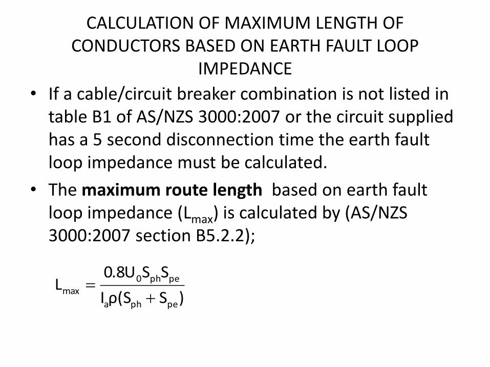
CALCULATION OF MAXIMUM LENGTH OF CONDUCTORS BASED ON EARTH FAULT LOOP
IMPEDANCE
• If a cable/circuit breaker combination is not listed intable B1 of AS/NZS 3000:2007 or the circuit suppliedhas a 5 second disconnection time the earth faultloop impedance must be calculated.
• The maximum route length based on earth faultloop impedance (Lmax) is calculated by (AS/NZS 3000:2007 section B5.2.2);
)Sρ(SI
SS0.8UL
pepha
peph0max

CALCULATION OF MAXIMUM LENGTH OF CONDUCTORS BASED ON EARTH FAULT LOOP
IMPEDANCE Where: Lmax = maximum route length in metres
U0 = the nominal phase voltage in volts (V)
ρ = resistivity at normal working temperature in Ω-mm2/m
(22.5 x 10⁻³ for copper and 36 x 10-3 for aluminium)
Ia = current causing instantaneous operation of the protective device in amperes (A), (the current that assures operation of the protective fuse concerned, in the specified time
Sph = cross sectional area of the active conductor of the circuit concerned in mm2
Spe = cross sectional area of the protective earthing conductor concerned in mm2
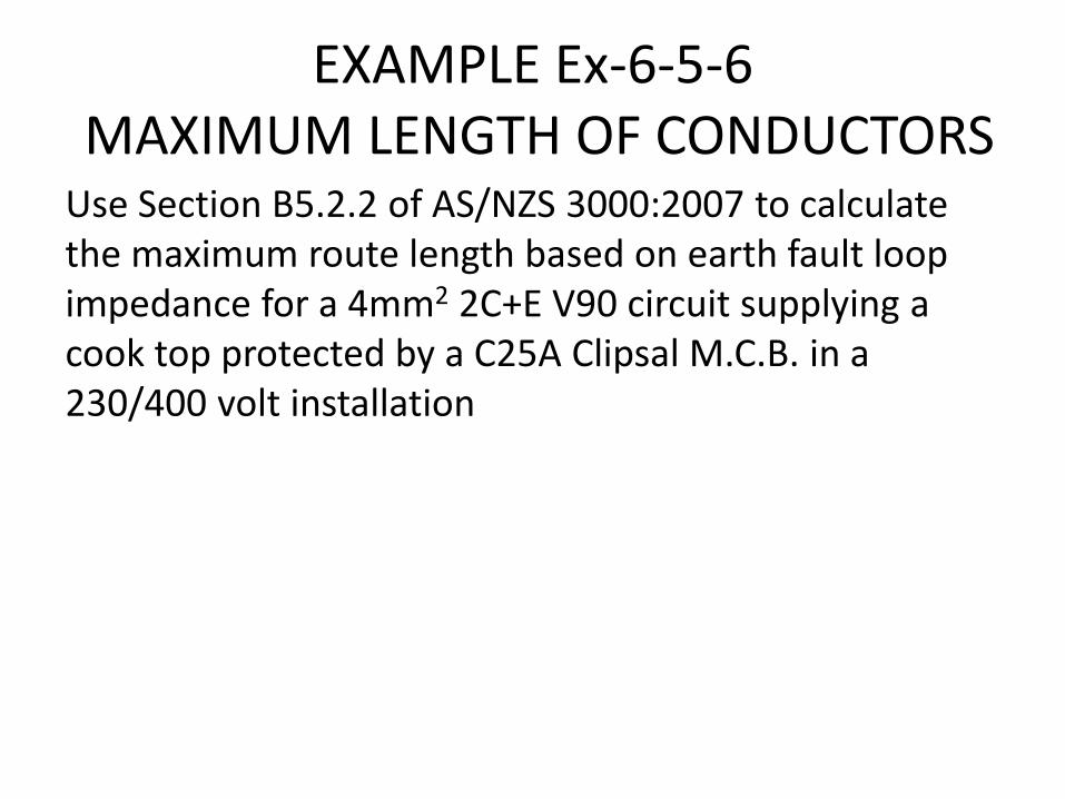
EXAMPLE Ex-6-5-6 MAXIMUM LENGTH OF CONDUCTORS Use Section B5.2.2 of AS/NZS 3000:2007 to calculate the maximum route length based on earth fault loop impedance for a 4mm2 2C+E V90 circuit supplying a cook top protected by a C25A Clipsal M.C.B. in a 230/400 volt installation
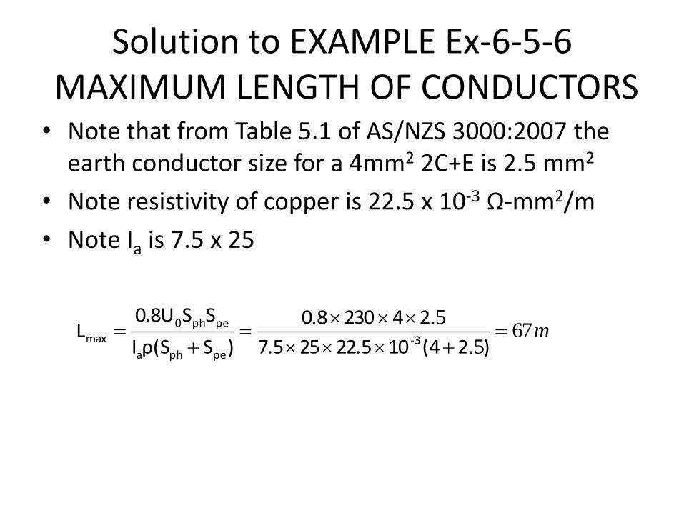
Solution to EXAMPLE Ex-6-5-6 MAXIMUM LENGTH OF CONDUCTORS • Note that from Table 5.1 of AS/NZS 3000:2007 the
earth conductor size for a 4mm2 2C+E is 2.5 mm2
• Note resistivity of copper is 22.5 x 10⁻³ Ω-mm2/m
• Note Ia is 7.5 x 25
m675.
5.
)2(41022.5257.5
242300.8
)Sρ(SI
SS0.8UL
3-pepha
peph0
max

CALCULATION OF MAXIMUM LENGTH OF CONDUCTORS BASED ON EARTH FAULT LOOP
IMPEDANCE • On a long run of cable, where cable size has been
increased to compensate for voltage drop, the maximumdemand (IB) will be much lower than the current carryingcapacity of the cable (IZ).
• See Example X-6-5-7 (Chapter 6, Topic 6-5 ) in Workbookfor analysis of a situation where both current carryingcapacity and voltage drop comply with AS/NZS3000:2007 requirements, but the earth fault loopimpedance does not.


![[1]. Mardreagus Williams Electrical Engineer -Electrical Subsystem Design - Hardware Design](https://img.dokumen.tips/doc/110x75/5697c00d1a28abf838cc9254/1-mardreagus-williams-electrical-engineer-electrical-subsystem-design-.jpg)