Embed Size (px)
Citation preview

SAFE-DRIVE™
IM-EN-SDI2-PGRev. 1.1
PR-23-SDSDI2-23-SN2-XSSDR2-23
POCKET GUIDE
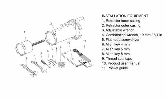
INSTALLATION EQUIPMENT
1. Retractor inner casing
2. Retractor outer casing
3. Adjustable wrench
4. Combination wrench, 19 mm / 3/4 in
5. Flat head screwdriver
6. Allen key 4 mm
7. Allen key 5 mm
8. Allen key 8 mm
9. Thread seal tape
10. Product user manual
11. Pocket guide

SAFETY REQUIREMENTS
Nozzle removal Nozzle insertion Sensor removal Sensor insertion
CONTENTS
Sensor insertion
Sensor removal
Wash nozzle insertion
Wash nozzle removal

SENSOR INSERTION
Sensor insertion
Sensor insertion
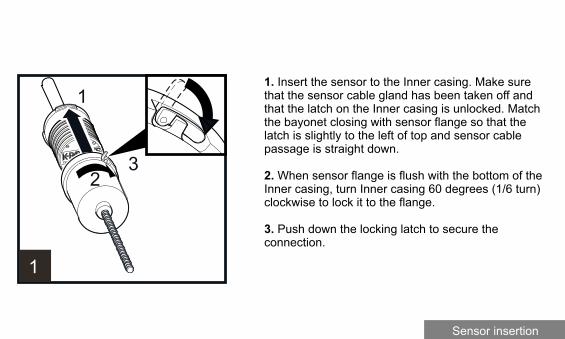
1. Insert the sensor to the Inner casing. Make sure that the sensor cable gland has been taken off and that the latch on the Inner casing is unlocked. Match the bayonet closing with sensor flange so that the latch is slightly to the left of top and sensor cable passage is straight down.
2. When sensor flange is flush with the bottom of the Inner casing, turn Inner casing 60 degrees (1/6 turn) clockwise to lock it to the flange.
3. Push down the locking latch to secure theconnection.
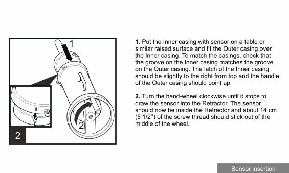
1. Put the Inner casing with sensor on a table or similar raised surface and fit the Outer casing over the Inner casing. To match the casings, check that the groove on the Inner casing matches the groove on the Outer casing. The latch of the Inner casing should be slightly to the right from top and the handle of the Outer casing should point up.
2. Turn the hand-wheel clockwise until it stops to draw the sensor into the Retractor. The sensor should now be inside the Retractor and about 14 cm (5 1/2’’) of the screw thread should stick out of the middle of the wheel.
Sensor insertion

Take a firm hold of the hand-wheel and the handle and lift the Retractor (with sensor) over the isolation valve flange. Keep handle up and make sure that the latch on the Outer casing is open.
Sensor insertion

1. Turn the Retractor 60 degrees clockwise (i.e. to the right) to lock the bayonet.
2. Push down the latch on the Outer casing to secure the connection.
3. Insert safety pin.
Sensor insertion

1. Close the blow-out ball valve underneath theisolation valve.
2. Lift up the isolation valve handle locking plate.
3. Open the isolation valve by turning the valve handle 90 degrees counterclockwise. The valve is open when the ball valve handle is parallel to the Retractor and sensor.
Sensor insertion

Now sensor can be inserted into the process. Turn the hand-wheel counterclockwise until it stops, i.e. until the sensor flange connects with the isolation valve and only the end of the screw thread is visible.
Sensor insertion

Fit the four M12 nuts to the bolts holding the sensor to the isolation valve and screw them on with a19 mm or 3/4" wrench.
Important: Do not tighten the nuts too hard, set the torque at 50 Nm (37 ft/lbs).
Sensor insertion
50Nm (37ft/lbs)

1. Turn the wheel 90 degrees (a quarter turn)clockwise.
2. Remove safety pin.
3. Unlock the latch of the Outer casing.
4. Turn the casing 60 degrees counterclockwise i.e. until the handle is up on top.
Sensor insertion

1. Turn the hand-wheel counterclockwise to drop the thread.
2. Lift off the Outer casing.
Sensor insertion

1. Lift up and pull the latch of the Inner casing to unlock.
2. Turn the casing 60 degrees counterclockwise to release it from the flange.
Sensor insertion

Lift the Inner casing away from the sensor head.
Sensor insertion

Power off the DTR. Connect sensor cable to the DTR.
1. Take off sensor nameplate and the gasketunderneath.
2. Put interconnecting cable through the cable gland.
3. Connect the interconnecting cable to the sensor.
4. Screw the cable gland to the sensor.
5. Fit the gasket and nameplate onto the sensor andscrew the nameplate back on.
Turn on DTR power to power up the Safe-Drive™.system.
Sensor insertion

SENSOR REMOVAL
Sensor removal

Sensor removal
Switch off the DTR to cut off power from the sensor.
1. Remove the sensor nameplate and the gasketunderneath.
2. Screw off the cable gland.
3. Disconnect the interconnecting cable.
4. Remove the cable from sensor.
5. Place gasket and nameplate on the sensor head and screw the sensor nameplate back on.
Note: If another inline sensor is connected to thesame DTR, disconnect the loose cable from the DTR and turn power on again.

1. Unlock the latch on Inner casing.
2. Lift the Inner casing over the sensor head. Connect the casing to the sensor flange bayonet.
Sensor removal
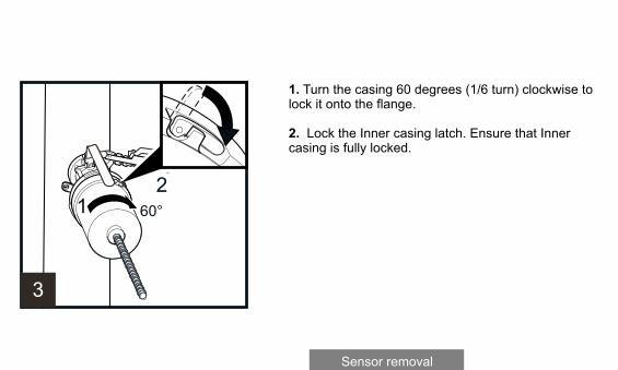
1. Turn the casing 60 degrees (1/6 turn) clockwise to lock it onto the flange.
2. Lock the Inner casing latch. Ensure that Inner casing is fully locked.
Sensor removal

1. Grab Outer casing with one hand on the handle and the other hand on the wheel. Fit the Outer casing over Inner casing and all the way to the isolation valve bayonet keeping the handle upwards.
2. Rotate the hand wheel clockwise to get thread of the Inner casing running through the wheel.
Sensor removal
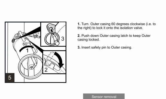
1. Turn Outer casing 60 degrees clockwise (i.e. to the right) to lock it onto the isolation valve.
2. Push down Outer casing latch to keep Outer casing locked.
3. Insert safety pin to Outer casing.
Sensor removal

Open and remove the four M12 nuts on the boltsholding the sensor to the isolation valve using a19 mm (3/4") wrench.
Sensor removal

1. Turn the hand wheel clockwise until it stops toremove the sensor from process.
2. At this stage about 140 mm (5.5") of the threadshould stick out from the middle of the wheel.
Sensor removal

1. Lift up the isolation valve handle locking plate.
2. Close the isolation valve on by turning the handle 90 degrees (a quarter turn) to the left.
Important: The isolation valve is properly closedwhen the handle points away from the sensor and the locking plate drops down over the handle.
3. Open the blow-out valve under the isolation valve for box cleaning to get rid of any process liquid inside the isolation valve.
Warning! Some process liquid will leak out throughthe small ball valve; beware of splashing!
Sensor removal
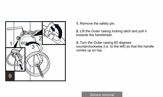
1. Remove the safety pin.
2. Lift the Outer casing locking latch and pull it towards the handwheel.
3. Turn the Outer casing 60 degrees counterclockwise (i.e. to the left) so that the handle comes up on top.
Sensor removal
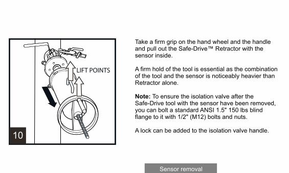
Take a firm grip on the hand wheel and the handleand pull out the Safe-Drive™ Retractor with the sensor inside.
A firm hold of the tool is essential as the combination of the tool and the sensor is noticeably heavier than Retractor alone.
Note: To ensure the isolation valve after theSafe-Drive tool with the sensor have been removed,you can bolt a standard ANSI 1.5" 150 lbs blind flange to it with 1/2" (M12) bolts and nuts.
A lock can be added to the isolation valve handle.
Sensor removal

Put the Safe-Drive™ Retractor with sensor onto a table or similar surface so that the hand wheel has space to turn.
1. Turn the wheel counterclockwise until the trapezoidal thread is all the way inside Outer casing and loose from the wheel, i.e. Outer casing is no longer connected to the parts inside.
2. Pull Outer casing off.
Sensor removal

1. Open the latch on Inner casing by lifting it up and pulling out.
2. Keep sensor steady with one hand and turn the Inner casing counterclockwise with the other hand to unlock Inner casing from sensor.
3. Pull off the sensor.
IMPORTANT: The sensor tip is hot and may be covered with liquor. Wash the sensor and valve with hot water immediately after the removal.
Sensor removal

WASH NOZZLE INSERTION
Nozzle insertion
Nozzle insertion
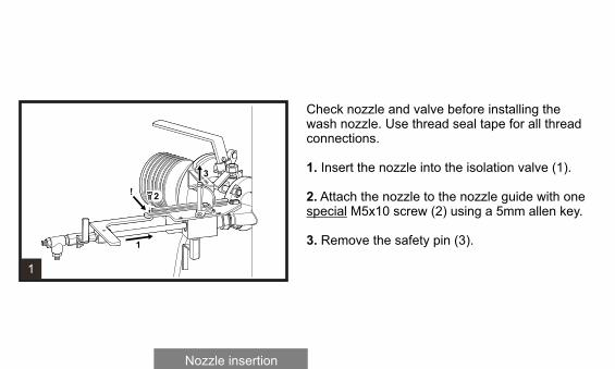
Check nozzle and valve before installing the wash nozzle. Use thread seal tape for all thread connections.
1. Insert the nozzle into the isolation valve (1).
2. Attach the nozzle to the nozzle guide with one special M5x10 screw (2) using a 5mm allen key.
3. Remove the safety pin (3).

1. Close the 1/4” check port valve under thenozzle isolation valve (1).
2. Open the isolation valve (2) by turning thehandle counterclockwise..
3. Push the nozzle to the process (3).
4. Attach the nozzle to the nozzle guide with oneM5x10 screw (4) using a 4mm allen key.
5. Lock the isolation valve handle with the safetypin (5).
Nozzle insertion

1. Connect the steam line and sensor flushflexible line to the nozzle T-piece (1, 2).
2. Open the steam supply line valve (3).
Nozzle insertion

WASH NOZZLE REMOVAL
Nozzle removal
Nozzle removal
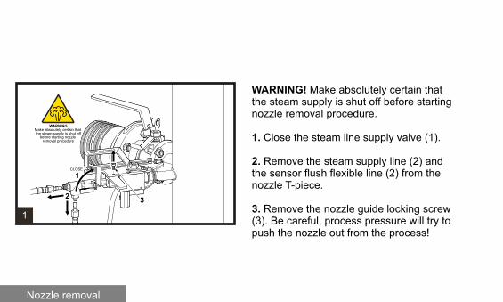
WARNING! Make absolutely certain that the steam supply is shut off before starting nozzle removal procedure.
1. Close the steam line supply valve (1).
2. Remove the steam supply line (2) and the sensor flush flexible line (2) from the nozzle T-piece.
3. Remove the nozzle guide locking screw (3). Be careful, process pressure will try to push the nozzle out from the process!

4. Remove the safety pin (4).
5. Slide the nozzle out from the process (5) until the guide plate stops it.
6. Close the nozzle isolation valve (6) by turning the handle clockwise.
7. Open the 1/4" check port valve under the nozzle isolation valve (7).
Nozzle removal

1. Lock the isolation valve handle with the safety pin. (1).
2. Remove the guide plate screw (2).
3. Remove the nozzle from the isolation valve completely (3).
Nozzle removal

K-PATENTS (SHANGHAI) CO., LTDRoom 1509, Tomson CommercialBuilding, No. 710Dongfang RDPudong District, Shanghai, ChinaTel. +86 21 5087 0597/0598Fax +86 21 5087 0598
K-PATENTS OYP.O. Box 7701511 Vantaa, FinlandTel. +358 207 291 570Fax +358 207 291 [email protected]
K-PATENTS, INC.1804 Centre Point Circle, Suite 106Naperville IL 60653, USATel. (630) 955 1545Fax (630) 955 [email protected]
www.kpatents.com