Embed Size (px)
Citation preview
Safe Design of Slabs incorporating Class L Mesh Latest design advice about AS 3600
Dr. Mark Patrick, MP Engineers Pty Limited
SRIA Technical Paper – November, 2005 (Published in part in Concrete in Australia, December 2005 – February 2006, pp. 23-27) 1
This brief article has been written to provide structural engineers with the latest design advice about using the recently-amended Concrete Structures Standard AS 3600–2001 [1], which contains some new rules for the safe design of conventional concrete slabs and beams incorporating 500 MPa Class L mesh as main reinforcement. The mesh can also control cracking due to shrinkage and temperature effects. Refinements to the popular simplified method for reinforced two-way slabs supported on four sides (Clause 7.3 of AS 3600), which reduce the amount of moment redistribution, are also useful for designing flexural members incorporating Class N reinforcement to reduce flexural cracking of concrete1 under in-service conditions.
Development of Full Plastic Hinge Mechanism In order that a full plastic hinge mechanism can form in a continuous concrete member with a given loading arrangement and distribution of reinforcement, the hinges must exhibit sufficient ductility to allow all of the necessary hinges to form. The distribution of plastic moments can differ from that determined using an elastic method of analysis, and hence moment redistribution may have to occur. In accordance with Clause 7.6 of AS 3600, a limit has been placed on the amount of moment redistribution that may be assumed in design depending on the value of the neutral axis parameter ku. For example, for over-reinforced peak moment regions (ku>0.4), which theoretically fail in flexure by crushing of the concrete compressive stress zone rather than tensile fracture of steel, no moment redistribution should be assumed in elastic design.
With the move to a standard strength grade of 500 MPa for hot-rolled deformed reinforcing bar and welded-wire mesh, two new ductility classes N (normal) and L (low) were defined in AS/NZS 4671 [2] and then referred to in AS 3600.
Experimental and numerical studies were undertaken to determine the minimum acceptable ductility of Class L, cold-reduced mesh, and associated design restrictions depending on the ductility demand and redundancy, for it to continue to be used as main reinforcement in suspended floors [3,4,5]. There had been no evidence of any structural problems due to its limited ductility in over 80 years of successful construction in Australia, and also, manufacturers of mesh had to improve its quality in order to meet the new, more-stringent minimum ductility requirements established jointly by the Standards Australia “Concrete Structures” and “Steel Reinforcing Materials” main committees as specified in AS/NZS 4671, and the broad engineering community through a formal public review process [6].
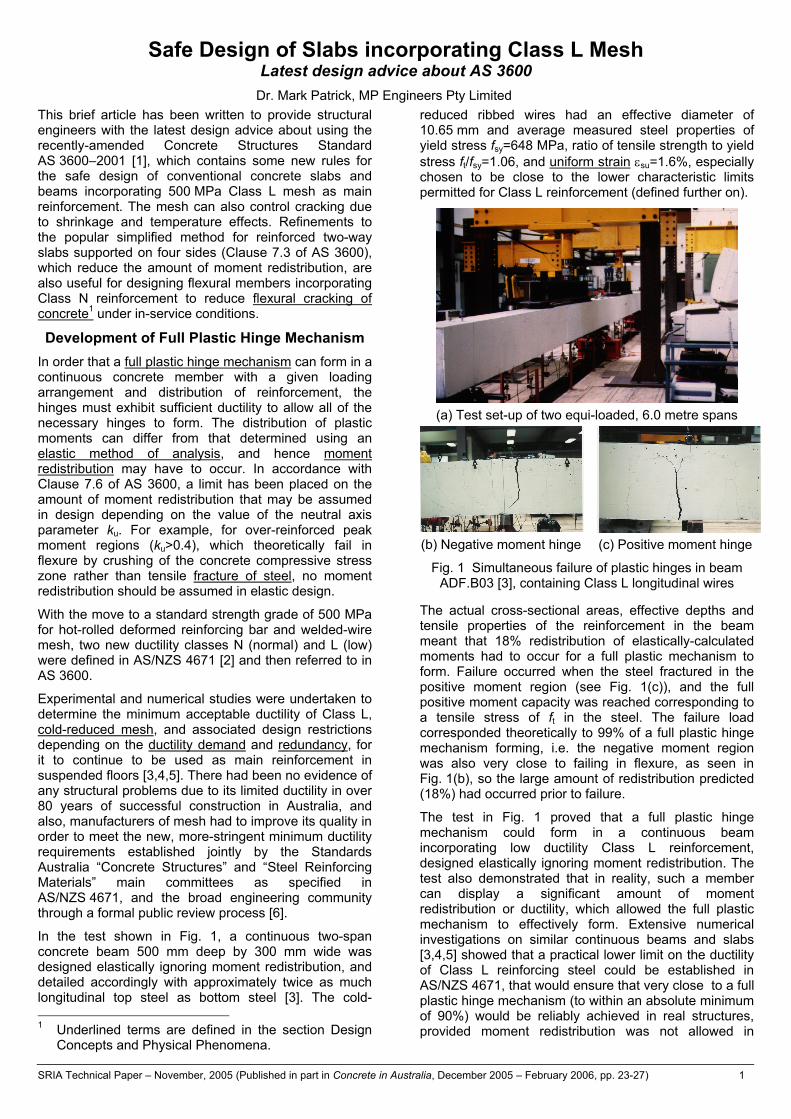
In the test shown in Fig. 1, a continuous two-span concrete beam 500 mm deep by 300 mm wide was designed elastically ignoring moment redistribution, and detailed accordingly with approximately twice as much longitudinal top steel as bottom steel [3]. The cold- 1 Underlined terms are defined in the section Design
Concepts and Physical Phenomena.
reduced ribbed wires had an effective diameter of 10.65 mm and average measured steel properties of yield stress fsy=648 MPa, ratio of tensile strength to yield stress ft/fsy=1.06, and uniform strain εsu=1.6%, especially chosen to be close to the lower characteristic limits permitted for Class L reinforcement (defined further on).
(a) Test set-up of two equi-loaded, 6.0 metre spans
(b) Negative moment hinge (c) Positive moment hinge
Fig. 1 Simultaneous failure of plastic hinges in beam ADF.B03 [3], containing Class L longitudinal wires
The actual cross-sectional areas, effective depths and tensile properties of the reinforcement in the beam meant that 18% redistribution of elastically-calculated moments had to occur for a full plastic mechanism to form. Failure occurred when the steel fractured in the positive moment region (see Fig. 1(c)), and the full positive moment capacity was reached corresponding to a tensile stress of ft in the steel. The failure load corresponded theoretically to 99% of a full plastic hinge mechanism forming, i.e. the negative moment region was also very close to failing in flexure, as seen in Fig. 1(b), so the large amount of redistribution predicted (18%) had occurred prior to failure.
The test in Fig. 1 proved that a full plastic hinge mechanism could form in a continuous beam incorporating low ductility Class L reinforcement, designed elastically ignoring moment redistribution. The test also demonstrated that in reality, such a member can display a significant amount of moment redistribution or ductility, which allowed the full plastic mechanism to effectively form. Extensive numerical investigations on similar continuous beams and slabs [3,4,5] showed that a practical lower limit on the ductility of Class L reinforcing steel could be established in AS/NZS 4671, that would ensure that very close to a full plastic hinge mechanism (to within an absolute minimum of 90%) would be reliably achieved in real structures, provided moment redistribution was not allowed in
Safe Design of Slabs incorporating Class L Mesh Latest design advice about AS 3600
SRIA Technical Paper – November, 2005 (Published in part in Concrete in Australia, December 2005 – February 2006, pp. 23-27) 2
design. This restriction had already been introduced into AS 3600 in an earlier amendment in 1996, before the move to 500 MPa reinforcement, as a precautionary measure.
It is worth pointing out several other aspects of the beam test, for further discussion in this article, viz.:
(a) the applied loads and reaction at mid-span were measured using load cells so that the distribution of bending moments could be accurately calculated at any stage of the test (with the spans and loading positions known accurately too);
(b) the hydraulic jacks applying the vertical loads were operated in position rather than load control, which prevented sudden or catastrophic collapse from occurring when maximum load was reached, noting that any concrete member (irrespective of its ductility) will fail catastrophically if tested under load control, which simulates gravity or conservative loading conditions;
(c) the close, regular spacing of the vertical flexural cracks visible in Figs 1(b) and (c) in both the negative and positive moment regions indicates that the ribbed wire developed strong bond representative of ribbed mesh or deformed bar, noting that a crack width of approximately 3 mm at bar height corresponded to steel fracture;
(d) the maximum mid-span deflection at failure reached approximately 32 mm or span/188, synonymous with a brittle failure, which was deemed acceptable in practice; and
(e) had the beam been designed in accordance with AS 3600 using nominal material properties, and bending strength had governed the design, then the maximum load reached would have equalled 0.99×648/500×1.06/0.8 = 1.70 times the factored design ultimate load, i.e. this assumes a strength reduction factor φ of 0.8, appropriate at the time to under-reinforced sections with Class L mesh.
An important assumption in AS 3600 is that the moment capacity or strength in bending of cross-sections can be calculated ignoring the ductility of the reinforcing steel, i.e. the basic principles in Clause 8.1.2.1 do not require possible fracture of the steel to be considered. The numerical studies [3,4,5] confirmed that this is a satisfactory assumption provided the uniform strain of the steel, εsu, is at least 1.5%. The results of a moment-curvature analysis for a rectangular section are shown in Fig. 2. These were obtained from a non-linear analysis assuming plane sections remain plane and using an elastic-plastic stress-strain curve for the reinforcement and the Desayi-Krishnan stress-strain curve for concrete. This later curve was chosen as the ultimate (maximum) moment occurs at an extreme concrete fibre strain of 0.003 provided the steel has yielded. It can be seen from Fig. 2 that even if the steel uniform strain εsu is limited to 1.5%, the moment capacity of the cross-section is virtually unaffected.
The moment capacity can also be accurately predicted using the rectangular stress block theory in AS 3600. Provided the steel has yielded, this calculation can be
performed without the need for a prescribed extreme concrete fibre strain i.e. εcu = 0.003. For higher steel percentages when the ultimate (maximum) moment is attained before the steel yields, the maximum moment is reached at an extreme concrete fibre strain greater than 0.003. However, what is important is that even if the steel uniform strain, εsu, is limited to 1.5%, the moment capacity of the peak moment regions can be accurately determined using current design procedures.
0
200
400
600
800
1000
1200
1400
0 20 40 60 80 100 120 140 160 180 200 220
Curvature (mm-1x10⁻⁶)
Ben
ding
Mom
ent
(kN
m/m
)
p = 0.005
p = 0.0025
p =0.00125
Locus M u maximum εcu=0.003εsu = 1.5%
εsu = 5% εsu = 10%
Fig. 2 Moment-curvature curves for rectangular section
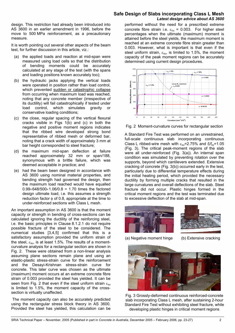
A Standard Fire Test was performed on an unrestrained, full-scale continuous slab incorporating continuous Class L ribbed-wire mesh with εsu=2.75% and ft/fsy=1.05 (Fig. 3). The critical peak-moment regions of the slab were all under-reinforced (Fig. 3(a)). An internal span condition was simulated by preventing rotation over the supports, beyond which cantilevers extended. Extensive cracking of concrete (Fig. 3(b)) occurred early in the test, particularly due to differential temperature effects during the initial heating period, which provided the necessary ductility by forming multiple cracks that resulted in the large curvatures and overall deflections of the slab. Steel fracture did not occur. Plastic hinges formed in the critical moment regions and the test was terminated due to excessive deflection of the slab at mid-span.
(a) Negative moment hinge (b) Extensive cracking
Fig. 3 Grossly-deformed continuous reinforced-concrete slab incorporating Class L mesh, after sustaining 2-hour Standard Fire Test without exhibiting steel fracture, while
developing plastic hinges in critical moment regions

Safe Design of Slabs incorporating Class L Mesh Latest design advice about AS 3600
SRIA Technical Paper – November, 2005 (Published in part in Concrete in Australia, December 2005 – February 2006, pp. 23-27) 3
New Amendment of AS 3600–2001 [1] Concrete Structures Standard AS 3600 includes a recent, important amendment that primarily addresses the use of Class L mesh as main reinforcement in the design of suspended, reinforced-concrete floors.
As explained in the previous section, no moment redistribution may be assumed during the design of members incorporating Class L mesh as main tensile reinforcement (noting that the flange of a T- or L-beam may include some mesh acting as tensile reinforcement in negative moment regions), so that the amount of moment redistribution required at ultimate load is limited. Accordingly, Clause 7.6.8.3 of AS 3600 has been amended to make this requirement clearer, where it is stated that:
(a) Beams or one-way slabs and supports – Reinforcement shall be provided to carry the elastic distributions of stresses at all locations.
(b) Two-way slab systems – The analysis shall model the slabs as a system of plates and supports. Reinforcement shall be provided to carry the elastic distribution of stresses (including calculated torsions) at all locations within the slab system.
The clause also includes a new penalty of 20% to be applied to the design strength in bending, φMuo, i.e. for under-reinforced or balanced sections (ku≤0.4) the strength reduction factor φ=0.8×0.8=0.64. This penalty does not apply to over-reinforced sections (ku>0.4) as steel fracture is theoretically not possible, but of course these would seldom occur in practice. The potential economic implications of this arbitrary penalty are discussed later in light of recent test results. It is supposed to take account of the effects of relative foundation movements, variations in loading arrangements and accidental loadings, which can lead to additional moment redistribution. It is also intended to penalise the potentially brittle nature of the failure mode, i.e. limited deflection before steel fracture as shown by the beam in Fig. 1, noting that the resultant value of φ=0.64 is similar to the minimum value for over-reinforced sections in bending of φ=0.6. More reinforcement may not be required, if instead minimum bending strength (Clause 8.1.4.1) governs the design.
The general principles of elastic design in AS 3600 for beams and slabs incorporating Class L mesh, as formally stated above, were applied in a numerical investigation of the popular simplified methods of structural analysis in Clause 7.2 for continuous beams and one-way slabs, and in Clause 7.3 for rectangular two-way slabs supported on four sides [7,8]. Modifications to these design rules allow the safe, continued use of Class L mesh by limiting the amount of moment redistribution at the strength limit state.
The simplified method for continuous beams and one-way slabs, the origin of which dates back to the 1950’s, only needed to be modified to a small extent.
A new table of elastic bending moment coefficients has been included in AS 3600, which is also useful for the
design of two-way rectangular slabs supported on four sides incorporating Class N reinforcing bars or mesh, since it limits the amount of redistribution that can occur under serviceability loads. Therefore, flexural crack control can be improved using the new table. The original table was derived using yield-line or plastic analysis, and dates back to the 1940’s. As a consequence, almost across the board in the new table, the design positive bending moments are reduced on average by about 15%, while the negative moments increase at continuous and discontinuous edges. Overall this typically relates to a theoretical increase in the total amount of reinforcing steel of about 10%, but this could increase to about 30% if Class L mesh is used (due to the reduced value of φ when calculating φMuo) and minimum bending strength (Clause 8.1.4.1) does not govern. The extent to which the amount of reinforcing steel will need to increase is also offset by the stepped changes in cross-sectional area of mesh.
Importantly, during the investigation the effects of support settlement were studied and found to be significant, i.e. slabs cast monolithically with beams were analysed. Therefore, use of the new table is restricted to slabs supported on walls when Class L mesh is used.
The amount of steel required in the edge strips is unchanged, including the corner torsional steel. Other deemed-to-comply reinforcement details covering the curtailment of main reinforcement are also unchanged.
A similar review of the simplified and idealized frame methods for two-way slabs in Clauses 7.4 and 7.5 of AS 3600 is planned, to investigate the use of Class L mesh as main reinforcement. In the meantime, designers may use linear elastic analysis in accordance with the design principles stated above for two-way slab systems. Finite element programs are readily available for this purpose, e.g. [9,10], which, however, must take into account torsional moments, and can then provide suitable orthogonal design bending moment contours (isorens) assuming no moment redistribution at the serviceability and strength limit states.
Ductility of Class L Mesh – AS/NZS 4671 [2] Improved ductility requirements for Class L mesh were introduced in 2001 when 500 MPa became the standard nominal yield strength for hot-rolled, deformed reinforcing bars and ribbed mesh. Australian Certification Authority for Reinforcing Steel (ACRS) certified reinforcing manufacturers and processors have been consistently improving their long-term quality to meet the more stringent ductility requirements, and now produce finished reinforcement including Class L mesh, with average properties well above the minimum ductility requirements [11], and of better quality than ever before.
Minimum ductility requirements
Uniform strain, εsu, and the ratio of tensile strength to yield stress, ft/fsy, in a tensile test of a reinforcing bar or wire are used to define minimum ductility requirements for reinforcing steels (bars, wire and mesh). These properties are known to affect the moment-rotation behaviour of plastic hinges. Long-term, minimum lower

Safe Design of Slabs incorporating Class L Mesh Latest design advice about AS 3600
SRIA Technical Paper – November, 2005 (Published in part in Concrete in Australia, December 2005 – February 2006, pp. 23-27) 4
characteristic values for Class L mesh are εsuk=1.5% and (ft/fsy)k=1.03, compared with εsuk=5% and (ft/fsy)k=1.08 for Class N (bar or mesh) reinforcement. Class E reinforcement for earthquake design is not available in Australia. The maximum yield stress is also limited.
Results from latest ACRS survey
The Australian Certification Authority for Reinforcing Steel has published the first long-term quality, tensile testing data obtained from manufacturers and processors supplying reinforcing steels in Australia [11].
For Class L mesh, indicative lower characteristic values significantly exceed the minimum ductility requirements in AS/NZS 4671. Combined results from ten mesh manufacturers for the most commonly produced SL72 mesh gave 90% confidence level values εsuk.9=2.76% (mean >4%) and (ft/fsy)k.9=1.04 (mean >1.07). For all the sizes examined, εsuk.9 varied from 1.9% to almost 4%.
Distribution Yield StrengSL 62 mesh
0
0.002
0.004
0.006
0.008
0.01
0.012
0.014
0.016
0.018
400 450 500 550 600 650 700 750
Site #4Site #6
(a) Yield stress distribution curves
A gt Distributionfor SL62 Mesh
0
0.1
0.2
0.3
0.4
0.5
0.6
0.7
0.8
0.9
0 0.5 1 1.5 2 2.5 3 3.5 4 4.5 5 5.5 6 6.5
Percent Elongation
Site #4
Site #6
(b) Uniform strain distribution curves
Fig. 4 Examples of Class L data from two manufacturing sites in ACRS survey, showing strength and ductility are normally inversely related, compensating each other [11]
Typical results for SL62 mesh are shown in Fig. 4: in Fig. 4(a), the distribution of yield stress (0.2% proof stress); and in Fig. 4(b), the distribution of uniform strain, the primary ductility parameter. The curves are for two manufacturing sites, and illustrate that higher strength is normally associated with lower ductility. For a continuous reinforced slab in flexure, this effect would be
taken into account in a strength reliability assessment, i.e. it is too conservative to assume that the lowest strength and the lowest ductility occur simultaneously in design cases when moment redistribution will occur.
Overseas requirements for reinforcement ductility
It has been explained that the Standards Australia “Concrete Structures” and “Steel Reinforcing Materials” committees have closely liaised to agree upon realistic material properties and develop appropriate design rules for concrete members incorporating reinforcing steels. This has been occurring over the past decade, and has resulted in a carefully “engineered” solution, with significant economic advantages arising for the Australian construction industry by utilising the massive existing reinforcement manufacturing and processing infrastructure, thereby minimising the cost of producing Australian and imported reinforcing steels, and preventing restrictions on free trade by not specifying minimum properties that exceed overseas requirements.
The two classes of ribbed steel reinforcement defined in Eurocode 2, Part 1.1 [12] directly comparable to Australian Classes L and N are Classes A and B, respectively. The minimum properties of characteristic 500 MPa yield stress reinforcement in the UK, for use with Eurocode 2, are εsuk=2.5% and (ft/fsy)k=1.05 for Class A, and εsuk=5% and (ft/fsy)k=1.08 for Class B reinforcement which are exactly the same as for Class N [13]. On account of the higher ductility requirement for Class A reinforcement than Class L, up to 20% moment redistribution may be assumed when designing members incorporating Class A reinforcement. For Class B reinforcement, a maximum of 30% moment redistribution may be assumed in elastic design, the same as in AS 3600 for Class N steel. It follows from the ACRS survey that typical (average) Class L mesh in Australia would satisfy the minimum ductility requirements for Class A reinforcement. The move toward Eurocode 2 in the UK has meant that the ductility requirements for mesh specified in the relevant British Standards for reinforcing steels have become more stringent, as occurred in Australia with the introduction of AS/NZS 4671, which is also based on this most modern, European approach.
In North America, cold-reduced mesh may be made from plain or deformed (ribbed) wire tested according to Standards ASTM A82 [14] and ASTM A496 [15], respectively. For this purpose, ASTM A82 requires plain wire to have a minimum yield stress of 450 MPa and minimum tensile strength of 515 MPa. It must also pass a reduction of area test and a bend test. Similarly, ASTM A496 requires ribbed wire to have a minimum yield stress of 485 MPa and minimum tensile strength of 550 MPa, and to pass a bend test. There is no specific minimum requirement for the ratio of tensile strength to yield stress, and neither is there for elongation after fracture or uniform strain, so the requirements are much less stringent than in Australia. McCabe [16] states that yield strengths for wires ranging in diameter from 5 to 19 mm are typically 560 MPa, while in practice the design yield stress has to be reduced to 420 MPa unless the shape of the stress-strain curve is known [17].
Normal probability density functions
Normal probability density functions

Safe Design of Slabs incorporating Class L Mesh Latest design advice about AS 3600
SRIA Technical Paper – November, 2005 (Published in part in Concrete in Australia, December 2005 – February 2006, pp. 23-27) 5
Design Concepts & Physical Phenomena The following simple design concepts and physical phenomena are described for the purposes of this article, and where applicable conform to AS 3600.
Amount of moment redistribution, β – defined at a critical section under peak moment by the percentage of the bending moment before redistribution, using one of the following formulae as appropriate (note: negative moment redistribution is taken herein as when the absolute value of the elastic moment is reduced, such that M* / M*e <1 or M / Me <1):
for design: β = -100(1 – M* / M*e), where M* is the design bending moment and M*e the elastically-determined design bending moment before moment redistribution, under the same design actions; or during a test: β = -100(1 – M / Me), where M is the actual bending moment and Me the elastically-determined bending moment before moment redistribution, under the same applied actions.
-100%
-30%
+30%
0%
Fig. 5 Example of moment redistribution in a uniformly-
loaded end span, where the heavy line is the elastic bending moment diagram with 0% redistribution – M*e or Me is the corresponding elastic internal support moment
Cold-reduced mesh – low ductility, welded-wire mesh with wires made by cold-reduction of hot-rolled structural-grade wire, normally ribbed in the same operation. Ductility demand – the level of ductility or plastic deformation required in the critical regions of the system, in order to allow sufficient moment redistribution to occur to satisfy the assumptions made in the method of analysis. Elastic method of analysis – the simplifying design assumption that the gross, uncracked section/s can be used to calculate the distribution of bending moments at ultimate load. Flexural cracking of concrete – cracking primarily induced by bending of cross-sections where the tensile strength of concrete is exceeded at the extreme fibre. Fracture of (reinforcing) steel – a normal physical phenomenon that occurs in under-reinforced flexural members incorporating Class L or N reinforcing steels, after the steel has reached its (peak) tensile strength, ft, which corresponds to the onset of necking at strain εsu. Full plastic hinge mechanism – formation of sufficient plastic hinges in a span to cause collapse. Imminent warning of collapse – the simplistic concept that building occupants will be safe if its members
cannot collapse without deflecting significantly, noting that for many forms of construction this is impossible to achieve, e.g. cold-formed members, and accordingly it is not a mandatory requirement in Australian building Standards. Moment redistribution2 – in design, adjustment of the bending moment diagram at the strength limit state relative to the elastically-calculated design bending moment diagram and the actual distribution of design strength in bending, while maintaining equilibrium with the design loads; or in a test, the difference between the calculated and actual bending moment diagram, at any stage of loading, which can vary depending on the amount of cracking and other factors – see Amount of moment redistribution. Plastic analysis – the design assumption that sufficient plastic hinges form in peak-moment regions, their design strength in bending being limited by the design yield stress of the reinforcing steel. Redundancy – static indeterminacy with alternative load paths: even simply-supported slabs under concentrated loading can be redundant by redistributing action effects through two-way action.
Reinforcement bond – the transfer of longitudinal force between reinforcing steel and surrounding concrete. Strain localization – uneven distribution of strain in steel reinforcement at flexural cracks due to bond transfer. Sudden or catastrophic collapse or failure – complete collapse of a member when maximum load is reached and continues to be applied (e.g. gravity loading), preventing the post-peak response to be observed. Uniform strain, εsu – tensile strain at peak (engineering) stress, corresponding to the onset of necking.
Australian Test Results for One-Way Members Recent Australian tests performed on one-way beams and slabs incorporating Class L wire or mesh have shown that significant amounts of moment redistribution (as defined under Design Concepts and Physical Phenomena) can occur at all stages of loading.
For example, another concrete beam (ADF.B02), very similar to beam ADF.B03 seen in Fig. 1, was tested as part of the same investigation [3]. However, for beam ADF.B02 the quantity of main steel was the same in both the bottom and top faces, so contrary to AS 3600 the beam would have to redistribute moment a large amount to develop a full plastic hinge mechanism. As expected, the beam failed when the steel over the central support fractured. The beam still reached 90% of its full plastic strength. The amount of moment 2 This is the conventional definition adopted in
AS 3600 and used throughout the discussions in this article, to provide a measure of the ductility demand in a continuous member from when it initially behaves elastically. Another possible way of defining moment redistribution is to consider the change in bending moment at adjacent potential hinge locations after the formation of a hinge. However, it is difficult to interpret the significance of this change without knowing the increase in rotation of the hinge.

Safe Design of Slabs incorporating Class L Mesh Latest design advice about AS 3600
SRIA Technical Paper – November, 2005 (Published in part in Concrete in Australia, December 2005 – February 2006, pp. 23-27) 6
redistribution the peak moment regions experienced is shown in Fig. 6 as a function of the mid-span deflection of the beam spans. Initially the beam was uncracked, which is a sensitive stage of the test, noting that the stiff beam was poured on the loading floor and had to be lifted into the test rig, so some adjustment of the support reaction had to be made which would have affected the distribution of bending moments. The largest downwards movement of the bending moment diagram, with redistribution in the internal support region reaching as high as -60%, resulted due to flexural cracks developing over the internal support, reducing the flexural stiffness of this region. This was followed by the positive moment region cracking, and the bending moment diagram rising, thus reducing the amount of redistribution to about -40%, which then remained fairly static varying down to about -30% until the maximum applied load was approached. At maximum load, the beam exhibited redistribution of over -30% at the central support, and as the negative region softened with necking of the reinforcement occurring, redistribution in this region again reached -40%. The sections under the loading points nearest the end supports were where the positive moment was assumed to be a maximum, and where the redistribution in the positive moment region plotted in Fig. 6 was calculated, typically reaching about +20%.
-60
-40
-20
0
20
40
60
0 5 10 15 20 25 30
Average Mid-span Deflection (mm)
Perc
enta
ge R
edis
trib
utio
n
Negative moment region - internal support
Positive moment region - loading points nearest ends
Maximum applied load reached
Fig. 6 Plot of percentage moment redistribution as a function of beam deflection – beam ADF.B02 [3],
containing Class L longitudinal wires
A detailed review has been made of eight tests on 850 mm wide one-way slabs (S1 to S8) conducted at the University of New South Wales, reported by Smith and Gilbert [18,19,20]. Most of the lightly-reinforced slabs incorporated Class L mesh as main reinforcement with εsu varying from 2.4 to 3.0% and ft/fsy from 1.08 to 1.09. Some of the tests were performed under load control, simulating gravity or conservative loading. Therefore, the post-ultimate behaviour of these slabs could not be recorded. Fracture of the steel mesh led to complete collapse. In the case of a slab with Class N bar, the only reason the bars did not fracture in the test was because the stroke of the out-of-control jack was limited. In practice, complete collapse can also occur in real slabs irrespective of the ductility of the reinforcement.3 Video
3 The recent rock slip in a section of the Lane Cove
tunnel in Sydney, which severely undermined the
footage of some of the simply-supported slabs tested (which reached their peak strength at relatively small deflections) has been used in presentations to deliberately try to alarm engineers about catastrophic failure, who may not realise that the characteristics of the failure mode involving steel fracture are not specific to members incorporating Class L mesh. Many types of concrete members, including precast and prestressed forms, and members constructed with other types of materials, e.g. structural steel, cold-formed steel, composite steel-concrete with stud shear connectors, timber, etc. could display similar behaviour at failure under the test conditions employed. The amount of deformation real members display before collapse can depend on a large number of variables, including their span-to-depth ratio in the case of slabs, loading pattern, in-plane restraint, and the opportunity for alternative load paths to develop, for example by two-way action.
The review covered: the bending strength of the critical cross-sections; the design capacity of the cross-sections; the strength of the slabs based on elastic analysis with no moment redistribution; and the strength of the slabs assuming a full plastic hinge mechanism had formed. Unfortunately, no load cell was used at the mid-span reaction point of the continuous slabs, and hence the actual distribution of moments could not be determined at any stage of loading. There are a number of other aspects about the tests that are indeed difficult to explain, and this highlights the need for careful measurements of test data on which to base reliable conclusions about the performance of the slabs. The results of the review were presented to the Standards Australia BD-002 main committee, and will be published in the near future. Despite the shortcomings, the main conclusions drawn from the review of the UNSW tests were that:
(a) the actual moment capacity of all cross-sections with Class L mesh could be reliably calculated using the current procedures in AS 3600, as verified by the simply-supported slab tests;
(b) elastic design methods, with no moment redistribution assumed, gave conservative estimates of the strength of the continuous slabs, despite the distribution of top and bottom meshes not conforming to elastic design (AS 3600); and
corner of a block of residential units constructed of double-skin brickwork, was an excellent example of a real concrete slab failing under gravity loading. Extensive video footage televised nationally showed how the foundations and supporting brickwork of a corner of a ground-floor slab completely subsided over a period of about ten hours. The jolt to the building and sound from the collapsing foundations gave imminent warning of collapse to the occupants, who subsequently vacated it. Ultimately the slab, including a cantilever balcony, was left unsupported across its full diagonal width while still carrying about half the dead load of the wall above. At the instant of failure the slab appeared to collapse suddenly, but it and the floors above had been strong enough to sustain the extreme loads for many hours.

Safe Design of Slabs incorporating Class L Mesh Latest design advice about AS 3600
SRIA Technical Paper – November, 2005 (Published in part in Concrete in Australia, December 2005 – February 2006, pp. 23-27) 7
(c) as the actual moment distributions in the continuous slabs were not known, moment capacities of the critical cross-sections, corresponding to the collapse loads, had to be calculated from equilibrium, and for the range of possible scenarios, amounts of moment redistribution from 0 to 25% were predicted.
Gilbert [20] describes the effects that strain localization has on the deformation capacity of the slabs with mesh. Strain localization is simply another term for reinforcement bond. Slip occurs locally between steel and concrete when flexural cracks form, the extent of which depends upon a large number of factors. The crack width is affected by the strain distribution in the steel. At ultimate load when steel fracture is imminent, Adams et al. [21] have shown that the uniform strain, εsu, of ribbed reinforcement has a direct effect on the final width of the cracks. In tests on a range of Class L and N reinforcing steels, they found that the average maximum crack width at steel fracture (in mm), wmax=1.5εsu (εsu in %). Using the lower characteristic values for εsu in AS/NZS 4671 of 1.5 and 5.0 for Class L and N steel, respectively, this means that steel fracture can be expected to occur with mesh after the crack width reaches 2.25 mm, and after 7.5 mm when Class N bars are used. The overall deformation of a flexural concrete member under load is directly affected by the distribution and width of the cracks, and Adams et al. proposed a simple physical model for predicting the deflection of beams knowing the relationship between crack width and steel strain. Their tests also confirmed that steel ductility did not affect the moment capacity of critical cross-sections at ultimate load, which corresponded to the onset of steel necking.
Chick et al. [4] used a numerical model verified by the beam tests conducted by Patrick et al. [3] to investigate the effect that unexpected support settlement can have on the load-carrying capacity of a two-span (6.0 metres) concrete slab incorporating Class L or N reinforcement. They predicted that a differential settlement of span/250 (=24 mm) would reduce the load-carrying capacity by up to 12%, i.e. only 88% of the plastic collapse load was reached, indicating that the effect can be significant.
Siddique et al. [22,23] designed two continuous, one-way reinforced-concrete slabs incorporating Class L mesh using the simplified method for continuous beams and one-way slabs in Clause 7.2 of AS 3600 (importantly, ignoring the effects of support settlement, which is normal design practice, and using the normal value of φ=0.8), subjecting them to similar amounts of support settlement as the slabs analysed by Chick et al. Limited information about the tests has been published to date, but nevertheless the tests are important to this discussion as they demonstrated high levels of ductility and reserve strength of typical Class L slabs.
In Siddique et al. [22] some results are presented for the larger slab tested (overall depth 150 mm, width 600 mm, equal spans 5.0 metres). The mesh in the top and bottom faces of the critical regions of the slab had εsu equal to 2.87 and 3.42%, and ft/fsy equal to 1.055 and 1.060, respectively. Prior to applying symmetric gravity
load using concrete kentledge, the central support was raised 17 mm, i.e. span/294. This was a very significant loading event, potentially (based on elastic, uncracked section properties) causing the design strength in negative bending, φMuo
-, to be exceeded at the central support, and flexural cracks developed in the top face in this region, one each side of the thickened support. In the test these cracks would have reduced the flexural stiffness of the slab, and therefore the force needed to lift the slab at its central support.
The central reaction was measured, which was an improvement over the tests performed by Smith and Gilbert. However, it is clear from a photograph shown at failure that the slab must have been unexpectedly strong, and additional, non-uniformly distributed kentledge had to be added. This would have to be taken into account in order to accurately calculate the distribution of bending moments immediately prior to failure, but this information is missing from the paper. The maximum total load applied to each span (additional to the slab self-weight) is reported, at which point collapse supposedly occurred with the steel fracturing at one of the first cracks to form at the central support. Siddique et al. describe the failure mode under the gravity loading as a “sudden brittle collapse”. However, immediately prior to the steel fracturing, the mid-span deflections had reached a significant amount of approximately span/100, which in normal circumstances would provide imminent warning of collapse. Catastrophic failure of the slab was inevitable due to gravity loads being applied to reach the maximum strength of the slab system. The extent to which a plastic hinge had formed in each of the positive moment regions of the slab is sensitive to the distribution of the applied loads, and plastic calculations performed using the information given in the paper, which allows the real ultimate moment capacities of the critical sections to be estimated, show that it is feasible that a full plastic hinge mechanism could have formed, noting also that extensive cracking of these regions was reported. The collapse load is given as being about 60% in excess of the factored, uniformly-distributed design ultimate load, but it may have been equivalently more than this, depending on how much it was biased towards the centre of each span. Siddique et al. also express concern that the reinforcement fractured. However, the reader will now understand that this is a natural phenomenon in any normal, under-reinforced concrete member that ultimately fails in flexure under gravity loading, and that this was not a consequence of the lower ductility of the steel compared to Class N.
In Siddique et al. [23] some results are presented for the smaller slab tested (overall depth 120 mm, width 600 mm, equal spans 4.0 metres). The mesh in the top and bottom faces of the critical regions of the slab had εsu equal to 3.42 and 1.67%, and ft/fsy equal to 1.060 and 1.044, respectively. In this case the central support was initially lowered 17 mm (span/235), rather than raised, which closed up some initial flexural cracks that had formed next to the central support due to self-weight. Elastic calculations ignoring cracking show that the whole of the slab could have been under significant
Safe Design of Slabs incorporating Class L Mesh Latest design advice about AS 3600
SRIA Technical Paper – November, 2005 (Published in part in Concrete in Australia, December 2005 – February 2006, pp. 23-27) 8
positive bending at this stage, i.e. up to about 75% of the design strength in positive bending, φMuo
+.
Once again, a photograph in their paper shows that at the maximum load just before collapse, the kentledge may have been non-uniformly distributed. What was surprising in this test was that once again the steel fractured at the central support, rather than may have been expected in the positive moment regions. Therefore, a very large amount of moment redistribution must have occurred while the slab was progressively being loaded to failure. The crack patterns illustrate that this would have occurred due to extensive flexural cracking of the positive moment regions, which would have reduced their flexural stiffness compared with the central support region, and this contributed to the significant rise of the bending moment diagram. Siddique et al. estimate that prior to collapse over -20% moment redistribution occurred in the peak positive moment regions, but very much more positive redistribution than this would have occurred in the central support region given the very large negative moment and lift of the bending moment diagram. As for the other slab, the collapse load is given as being about 60% in excess of the factored, uniformly-distributed design ultimate load. Plastic analysis of the slab system, using the actual properties of the materials, shows that approximately 90% of the plastic collapse load was reached in the test (assuming uniformly-distributed loads), despite the large downward settlement imposed.
As a final comment regarding the tests reported by Siddique et al., very substantial amounts of additional top and/or bottom reinforcing steel would have been required had support settlement been specifically designed for. Both tests confirmed that this would not have been necessary. By applying the increased design bending moments required by the amendment of Clause 7.2 of AS 3600 to limit moment redistribution, the new 20% penalty applied to φ, and designing for support settlement, over twice the area of steel would have been required in the critical regions in the test slabs. This would be a significant economic imposition in practice, and should be avoided whenever possible – see Recommended Design Procedure to AS 3600.
Anchorage and Splicing of Class L Mesh Class L mesh is a versatile reinforcing product favoured on many building sites for its simplicity, the accuracy and speed with which it can be placed, and its very short anchorage and splice (or lap) lengths on account of the strong anchorage provided by the transverse wires.
In contrast, anchorage and lap lengths for reinforcing bars are much larger, also because of their larger diameter normally. Mechanical splicing of reinforcing bars is an option, provided the ductility of the spliced bars is not reduced below the minimum requirements for Class N bars in AS/NZS 4671 [24,25]. Rules covering design and detailing of mechanical and welded splices, for possible inclusion in AS 3600, are still under development, noting that ductility is a critical issue being addressed.
Recommended Design Procedure to AS 3600 As a result of reviewing the most recent theoretical and experimental research investigations conducted in Australia into the use of Class L mesh as main reinforcement in reinforced-concrete slabs, it is recommended that the following design procedure be adopted when using AS 3600:
(a) use either of the simplified methods of analysis in Clauses 7.2 and 7.3 of AS 3600 to calculate the design action effects of applicable one-way beams and slabs, or two-way rectangular slabs supported on walls;
(b) alternatively, use the general principles of elastic analysis in Clause 7.6 of AS 3600, not assuming moment redistribution, and in two-way slabs take into account torsional moments;
(c) do not separately account for the effects of possible support settlement unless they are considered likely to be particularly large, i.e. more than equivalent to ±span/250 at ultimate load;
(d) when deemed applicable, design for flexural crack control by factoring down the elastically-determined peak bending moments appropriate to the serviceability conditions, and then satisfying the requirements of Clause 9.4.1;
(e) calculate the design strength in bending, φMuo, of critical under-reinforced sections in the normal manner using simple rectangular stress-block theory (Clause 8.1.2.2 of AS 3600): i. using a value of φ=0.64 if significant support
settlement is a distinct possibility but has not been directly taken into account when calculating the design moments; or otherwise
ii. using the normal value of φ=0.80, i.e. ignore the arbitrary penalty in AS 3600 (which potentially penalises a design twice for relative foundation movement), therefore ignoring the penalty imposed for supposed sudden failure;
and in this way determine the quantities of reinforcing steel required for flexure; and
(f) finally, detail the slabs so that the crack control provisions for shrinkage and temperature effects in Clause 9.4.3 of AS 3600 are satisfied in both the primary and secondary directions taking into account possible restraint effects.
The same procedure can be used when designing reinforced-concrete, combined beam and slab systems with Class L mesh contributing to the main tensile reinforcement in the beam flanges.
Conclusions A strong technical case for the continued use in Australia of suspended, reinforced-concrete slabs and beams of any proportions, incorporating improved-quality Class L mesh as main tensile reinforcement, has been presented. Consistent with the latest European developments, the basic arguments have been carefully considered and endorsed by Standards Australia main committee BD-002, resulting in important new
Safe Design of Slabs incorporating Class L Mesh Latest design advice about AS 3600
SRIA Technical Paper – November, 2005 (Published in part in Concrete in Australia, December 2005 – February 2006, pp. 23-27) 9
amendments to the Concrete Structures Standard AS 3600, that also account for the level of ductility of Australian and imported reinforcing steels achievable using existing reinforcement manufacturing and processing infrastructure. An essential requirement during design is to assume no moment redistribution, as in the newly-improved simplified or elastic analysis methods for continuous beams and one-way or two-way slabs. It has been shown that there is a growing body of local experimental evidence that shows that elastic design methods assuming no redistribution give conservative estimates of member strength appropriate for design. To avoid undue conservatism, it has been recommended that support settlement need only be taken into account in design if it is likely to exceed a value of span/250 at ultimate load, and to use φ=0.8 either when support settlement is directly taken into account, or when it is not considered significant.
References 1. Standards Australia, “Concrete Structures”,
AS 3600–2001 (incorporating Amendment Nos 1 & 2), 28th Oct., 2004.
2. Standards Australia, “Steel Reinforcing Materials”, AS/NZS 4671–2001 (incorporating Amendment No. 1), 5th June, 2003.
3. Patrick, M., Akbarshahi, E. and Warner, R.F., “Ductility Limits for the Design of Concrete Structures containing High-Strength, Low-Elongation Steel Reinforcement”, Proc. 18th Biennial Conf., CIA, Adel., May, 1997, pp. 509-517.
4. Chick, C., Patrick, M. and Wong, K., “Ductility of Reinforced-Concrete Beams and Slabs, and AS 3600 Design Requirements”, Proc. 19th Biennial CIA Conf., Sydney, May, 1999, pp. 570-578.
5. Patrick, M., Turner, M.D. and Warner, R.F., “Utilisation of Ductility of 500 MPa Steel Reinforcement in Reinforced-Concrete Structures designed to AS 3600–2001”, Proc. 20th Biennial CIA Conf., Perth, Sept., 2001, pp. 605-611.
6. Turner, M.D., “Introduction of 500 MPa Reinforcing Steel and its Effect on AS 3600”, Proc. 19th Biennial CIA Conf., Sydney, May, 1999, pp. 579-584.
7. Patrick, M., Wheeler, A., Turner, M., Marsden, W. and Sanders, P., “Important New Code Developments for Designing Reinforced-Concrete Continuous Beams, and One-way and Two-Way Slabs incorporating Class L or Class N Main Reinforcement“, ASEC2005, Australian Structural Engineering Conf., Newcastle, Sept., 2005.
8. Patrick, M., Wheeler, A., Turner, M., Marsden, W. and Sanders, P., “Improved Simplified Design Methods for Reinforced Continuous Beams and One-way Slabs, and Two-Way Slabs Supported on Four Sides“, Proc. 22nd Biennial CIA Conf., Melbourne, Oct., 2005.
9. Inducta Engineering, “SLABS Computer Program – new version with torsion”, www.inducta.com.au.
10. Rombach, G.A., “Finite Element Design of Concrete Structures”, Thomas Telford, London, 2004.
11. Fenwick, J.M., Pritchard, R.W. and Turner, M.D., “Long-term Quality of Steel Reinforcement and
Strand – Implications for Concrete Design”, Proc. 22nd Biennial CIA Conf., Melbourne, Oct., 2005.
12. British Standards Institution, “Eurocode 2: Design of Concrete Structures – Part 1.1, General Rules and Rules for Buildings”, BS EN 1992-1-1:2004.
13. Brooker, O., “How to Design Concrete Structures using Eurocode 2: Getting Started”, The Concrete Centre, June, 2005.
14. ASTM International, “Standard Specification for Steel Wire, Plain, for Concrete Reinforcement”, ASTM A82-97a, 10 December, 2001 (referenced in ACI 318-02, now superseded by ASTM A82-02, 10 Sept., 2002).
15. ASTM International, “Standard Specification for Steel Wire, Deformed, for Concrete Reinforcement”, ASTM A496-97a, 10 December, 2001 (referenced in ACI 318-02, now superseded by ASTM A496-02, 10 Sept., 2002).
16. McCabe, S.L., “State of the Art Report: Splicing of Reinforcement for Concrete Structures in the United States”, Proc. First International Conf. on Splices of Reinforcement, Japan Pressure Welding Society, Oct. 11, 2002.
17. American Concrete Institute, “Building Code Requirements for Structural Concrete (ACI 318-02) and Commentary (ACI 318R-02)”, January, 2002.
18. Smith, S.T. and Gilbert, R.I., “Tests on RC Slabs Reinforced with 500 MPa Welded Wire Fabric”, Proc. 21st Biennial Conf., CIA, Brisbane, July, 2003, pp. 561-570.
19. Gilbert, R.I. and Smith, S.T., “Strain Localization and Its Impact on the Ductility of Reinforced Concrete Slabs containing 500 MPa Reinforcement”, Proc. 18th Aust. Conf. Mechs Structures & Materials, Developments in Mechanics of Structures and Materials (ACMSM18) – Deeks & Hao (eds), Vol. 2, 2005, pp. 811-817.
20. Gilbert, R.I., “Strain Localization and Ductility of Reinforced Concrete Slabs”, ASEC2005, Australian Structural Engineering Conf., Newcastle, Sept., 2005.
21. Adams, J., Walsh, P., Marsden, M. and Patrick, M., “Factors Affecting the Ductility of Stiffened Rafts”, Proc. 19th Biennial CIA Conf., Sydney, May, 1999, pp. 255-263.
22. Siddique, U., Goldsworthy, H. and Gravina, R.J., “Ductility of 500 MPa Class L Mesh and Possible Support Settlement Effects”, Proc. 18th Aust. Conf. Mechs Structures & Materials, Developments in Mechanics of Structures and Materials (ACMSM18) – Deeks & Hao (eds), Vol. 2, 2005, pp. 873-878.
23. Siddique, U., “Behaviour of One-Way Continuous Reinforced Concrete Slabs, constructed with Grade 500 Class L Mesh Steel, under Support Settlement”, Proc. 22nd Biennial CIA Conf., Melbourne, Oct., 2005.
24. Patrick, M., Berry, P.A. and Bridge, R.Q., “Strength and Ductility of Mechanically Spliced Bars”, Proc. 20th Biennial CIA Conf., Perth, Sept., 2001, pp. 547-556.
25. Patrick, M., Berry, P.A., Zhang, L. and Marsden, W., “Important New Design Provisions for Mechanical and Welded Splices in AS 3600”, Proc. 21st Biennial CIA Conf., Brisbane, July, 2003.