Embed Size (px)
Citation preview

Sadia Garments Ltd.390/3/C,D IT Road, West Rampura, Bangladesh
(23.764006N, 90.42066E)
8 April 2014
1

2
Observations
3
Highly stressed columns in Building 2

4
Highly stressed columns in Building 2
Outline calculations indicate that working stress is high in columns in Building 2.
Red brick aggregate observed in columns in Building 2.
A Detailed Engineering Assessment of the building is required (see attached Scope) . Engineer is to perform detailed calculations based on as constructed dimensions and concrete tests to prove column size and (if required).
Load management plan to be implemented (see Observation 2).
Red brick aggregate observed

5
Concentrated areas of high loading

6
Concentrated areas of high loading
Concentrated areas of high loading observed throughout buildings. No loading management system in place.
2 number 10000 litre water tanks on roof of Building 1. Water tanks also observed on roof of Buildings 2 and 3.
Building 1 water tanks
Building 2 roof storage
Building 2

7
Cracking in structural elements
8
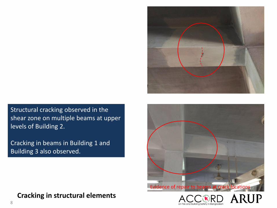
Cracking in structural elements
Structural cracking observed in the shear zone on multiple beams at upper levels of Building 2.
Cracking in beams in Building 1 and Building 3 also observed.
Evidence of repair to beams at crack locations

9
Complete as-built drawings for Building 3

10
No structural design information or drawings was available for survey team review for Building 3.Column sizes observed in Building 1 and 2 do not match structural drawings provided for review.
Complete as-built drawings for Building 3
Building 3 permit drawing

11
Non-engineered structures

12
Escape stairs to Building 1 and Building 2 appear to be non-engineered.
Non-engineered structures
Lightweight tin roof susceptible to wind uplift. Tin shed appears to be non-engineered with no apparent lateral stability system or bracing.
Shed at roof level of Building 2

13
Priority Actions

14
Problems Observed
1. Highly stressed columns in Building 22. Concentrated areas of high loading3. Cracking in structural elements4. Structural drawings for Building 3 to be completed5. Non-engineered structures

15
Item No. Observation Recommended Action Plan Recommended Timeline
1Highly stressed columns in
Building 2
Factory Engineer to review design, loads and columns stresses in all columns. Limit loads to a maximum iof 2kPa on all floors
Immediate - Now
2Highly stressed columns in
Building 2
Verify insitu concrete stresses either by 100mm diameter cores or existing cylinder strength data for cores from minimum 4 columns.
Immediate - Now
3Highly stressed columns in
Building 2A Detail Engineering Assessment (DEA) of Building 2 to be commenced, see attached Scope.
Immediate - Now
4Highly stressed columns in
Building 2DEA to be completed. 6-weeks
5Highly stressed columns in
Building 2
Factory Engineer to design and detail strengthening/remedial works for columns, as required by DEA.
6-weeks
6Highly stressed columns in
Building 2Strengthening/remedial works to columns to be implemented.
6-weeks
7Highly stressed columns in
Building 2Strengthening/remedial works to columns to be completed.
6-months

16
This Schedule develops a minimum level of information, Analysis and testing expected as part of a Detail Engineering Assessment.The Building(s) have been visually assessed and it is deemed necessary that a detailed engineering assessment be carried out by a competent Engineering Team employed by the factory Owner. This Request should be read in conjunction with the BUET developed Tripartite Guideline document for Assessment of Structural Integrity of Existing RMG Factory Buildings in Bangladesh (Tripartite Document), the latest version of this document should be referenced. T his document also gives guidance on required competency of Engineering Team.
We expect that the following will be carried out:1. Development of Full Engineering As-Built Drawings showing Structure, loading, elements, dimensions , levels, foundations and framing on Plan,
Section and Elevational drawings .2. The Engineering team are to carry out supporting calculations with a model based design check to assess the safety and serviceability of the building
against loading as set out in BNBC-2006, Lower rate provisions can be applied in accordance with the Tripartite Guidelines following international engineering practice, justification for these lower rate provisions must be made.
3. A geotechnical Report describing ground conditions and commenting on foundation systems used/proposed.4. A report on Engineering tests carried out to justify material strengths and reinforcement content in all key elements studied.5. Detailed load plans shall be prepared for each level showing current and potential future loading with all key equipment items shown with associated
loads.6. The Engineering team will prepare an assessment report that covers the following:
• As-Built drawings including• Plans at each level calling up and dimensioning all structural components • Cross sectional drawings showing structural beams, slabs, floor to floor heights, roof build-ups and Basic design information of the
structure• Highlight any variation between As-built compared to the designed structure• Results of testing for strength and materials• Results of geotechnical assessment and testing/investigation• Details of loading, inputs and results of computer modelling• Commentary on adequacy/inadequacy of elements of the structure• Schedule of any required retrofitting required for safety or performance of Structure
Any proposals for Retrofitting to follow guidance developed in the Tripartite Document
Detail Engineering Assessment

17
Item No. Observation Recommended Action Plan Recommended Timeline
8Concentrated areas of high
loading
All uses and storage on suspended floors to be reduced to maximum of loading of 2kN/m2 (200kg/m2) until DEA is completed and load plans are developed by Factory Engineer.
Immediate - Now
9Concentrated areas of high
loading
Factory Engineer to develop a loading plan for all floor plates within Building 1, Building 2 and Building 3 accounting for usage, floor build ups, solid partition walls and areas of concentrated loading.
6-weeks
10Concentrated areas of high
loadingFactory management to implement load plans. 6-weeks
11Concentrated areas of high
loadingContinue to implement load plans. 6-months
12Cracking in structural
elements
Factory Engineer to investigate structural cracking in slabs, beams and columns (opening up of plaster and inspect) in all factory buildings.
6-weeks
13Cracking in structural
elementsRecord and monitor location, size and width of all structural cracking.
6-weeks
14Cracking in structural
elementsFactory Engineer to develop strengthening/remedial details as required. Refer to Note 1.
6-weeks
15Cracking in structural
elementsContinue to monitor structural cracking throughout factory complex.
6-months

18
Item No. Observation Recommended Action Plan Recommended Timeline
16Structural drawings for
Building 3 to be completedFactory Engineer to complete as-built drawings for Building 3.
6-months
17Structural drawings for
Building 3 to be completedFactory Engineer to update as-built drawings for Building 1 and Building 2 based on column sizes observed on site.
6-months
18Structural drawings for
Building 3 to be completed
As-built drawings for Building 1, Building 2 and Building 3 to be updated, as required, following future modifications and strengthening works to structural elements.
6-months
19 Non-engineered structures
Factory Engineer to review the adequacy of non-engineered sheds and escape stairs within the complex. Particular attention to be paid to i) lateral stability and ii) connection details.
6-months