Embed Size (px)
Citation preview
SIMATIC
S7-PLCSIM V5.0
User Manual
Edition 06/2001 2809918-0002
Safety GuidelinesThis manual contains notices which you should observe to ensure your own personal safety, as well as toprotect the product and connected equipment. These notices are highlighted in the manual by a warningtriangle and are marked as follows according to the level of danger:
DangerIndicates an imminently hazardous situation which, if not avoided, will result in death or seriousinjury.
WarningIndicates a potentially hazardous situation which, if not avoided, could result in death or severeinjury.
CautionUsed with the safety alert symbol indicates a potentially hazardous situation which, if not avoided,may result in minor or moderate injury.
CautionUsed without the safety alert symbol indicates a potentially hazardous situation which, if not avoided,may result in property damage.
NoticeNOTICE used without the safety alert symbol indicates a potential situation which, if not avoided,may result in an undesirable result or state.
Qualified PersonnelThe device/system may only be set up and operated in conjunction with this manual. Only qualifiedpersonnel should be allowed to install and work on this equipment. Qualified persons are defined as personswho are authorized to commission, to ground, and to tag circuits, equipment, and systems in accordancewith established safety practices and standards.
Correct UsageNote the following:
WarningThis device and its components may only be used for the applications described in the catalog or thetechnical descriptions and only in connection with devices or components from other manufacturerswhich have been approved or recommended by Siemens.
This product can only function correctly and safely if it is transported, stored, set up, and installedcorrectly, and operated and maintained as recommended.
TrademarksSiemens® and SIMATIC® are registered trademarks of SIEMENS AG.STEP 7™ and S7™are trademarks of SIEMENS AG.Microsoft ®, Windows ®, Windows 95 ®, Windows 98 ®, Windows NT ®, Windows ME ®, and Windows 2000 ®are registered trademarks of Microsoft Corporation.Copyright Siemens Energy & Automation, Inc. 2001All rights reservedThe reproduction, transmission or use of this document or itscontents is not permitted without express written authority.Offenders will be liable for damages. All rights, includingrights created by patent grant or registration of a utility modelor design, are reserved.
Disclaimer of LiabilityWe have checked the contents of this manual foragreement with the hardware and software described.Because deviations cannot be precluded entirely, wecannot guarantee full agreement. However, the data in thismanual are reviewed regularly and any necessarycorrections included in subsequent editions. Suggestionsfor improvement are welcomed.
Siemens Energy & Automation, ISBU1 Internet PlazaJohnson City, TN 37602-4991, USA
© Siemens Energy & Automation, Inc. 2001
Technical data subject to change.
Contents
iii
Contents
Product Overview................................................................................................1
Introduction ..................................................................................................................1What's New in S7-PLCSIM, Version 5.0.......................................................................3Getting Started .............................................................................................................4Differences from a Real S7 PLC...................................................................................6S7-PLCSIM Main Window............................................................................................8CPU Operating Modes .................................................................................................9CPU Indicators ...........................................................................................................10Memory Areas............................................................................................................10
Basic Tasks .......................................................................................................11
Starting the Simulation ...............................................................................................11Using Help .................................................................................................................12Opening a Simulated PLC..........................................................................................14Opening a Layout .......................................................................................................15Selecting Scan Mode Options ....................................................................................16Changing CPU Operating Modes ...............................................................................17Monitoring the Simulated Program .............................................................................18Using the Slider Control .............................................................................................19Using S7-PLCSIM to Debug Your Program................................................................20Using Interrupt OBs in Your Program .........................................................................21Modifying Your Hardware Configuration .....................................................................22Downloading the Modified Configuration ....................................................................23Resetting the CPU Memory........................................................................................23Resetting Timers ........................................................................................................23

Contents
iv
Using Symbolic Addressing........................................................................................24Configuring an MPI Address.......................................................................................24Using Record/Playback ..............................................................................................25Monitoring the Scan Cycle..........................................................................................28Saving a Layout .........................................................................................................28Saving a Simulated PLC.............................................................................................29Closing a Simulated PLC............................................................................................30Ending the Simulation Session...................................................................................30
View Objects......................................................................................................31
S7-PLCSIM View Objects...........................................................................................31CPU View Object .......................................................................................................32ACCUs & Status Word View Object ...........................................................................32Block Regs View Object .............................................................................................32Stacks View Object ....................................................................................................32Input Variable View Object .........................................................................................33Output Variable View Object ......................................................................................33Bit Memory View Object .............................................................................................34Timer View Object ......................................................................................................34Counter View Object ..................................................................................................34Generic Variable View Object.....................................................................................35Vertical Bits Variable View Object ..............................................................................36
Error and Interrupt OBs....................................................................................37
Hardware Interrupt (OB40-OB47)...............................................................................37I/O Redundancy Error (OB70) ....................................................................................39CPU Redundancy Error (OB72) .................................................................................40Communication Redundancy Error (OB73) ................................................................42Time Error (OB80)......................................................................................................43Diagnostic Interrupt (OB82)........................................................................................44Insert/Remove Module Interrupt (OB83).....................................................................46Priority Class Error (OB85).........................................................................................47Rack Failure (OB86)...................................................................................................48
Contents
v
Reference Information ......................................................................................51
S7-PLCSIM Toolbars .................................................................................................51S7-PLCSIM Menus.....................................................................................................52
File Menu ................................................................................................................................ 53Edit Menu................................................................................................................................ 55View Menu .............................................................................................................................. 56Insert Menu............................................................................................................................. 57PLC Menu............................................................................................................................... 58Execute Menu......................................................................................................................... 59Tools Menu ............................................................................................................................. 61Window Menu ......................................................................................................................... 62Help Menu .............................................................................................................................. 63Help Button ............................................................................................................................. 63
S7-PLCSIM Numeric Data Formats............................................................................64Troubleshooting Tips..................................................................................................65

Product Overview
1
Product OverviewIntroductionThe S7-PLCSIM software enables you to run and test your program on a simulatedprogrammable logic controller (PLC) that exists on your computer or programming device (suchas a PG 740). Because the simulation exists completely within the STEP 7 software, you do notneed to be connected to any S7 hardware (CPU or I/O modules). With the simulated S7 PLC, youcan test and debug programs for both the S7-300 and S7-400 CPUs as well as WinLC.S7-PLCSIM provides a simple interface for monitoring and modifying different parameters usedby the program (such as for turning inputs on and off). You can also use the various applicationsof the STEP 7 software while you are running your program on the simulated PLC. This allowsyou to use such tools as the variable table (VAT) to monitor and modify variables.
S7-PLCSIM FeaturesS7-PLCSIM simulates an S7 controller, and contains the following memory areas:Memory Area DescriptionTimers T 0 to T 511Memory bits 131,072 bits (16 Kbytes) of M memoryTotal addressableI/O memory
131,072 bits (16 Kbytes) of I/O memory
Process image(setable; updatedevery scan)
Maximum: 131,072 bits (16 Kbytes)Preset: 8192 bits (1024 bytes)
Local data (setable) Maximum: 64 KbytesPreset: 32 Kbytes
Logic blocks anddata blocks
2048 function blocks (FBs) and functions (FCs)4095 data blocks (DBs)
System functionblocks (SFBs)
SFB0, SFB1, SFB2, SFB3, SFB4, SFB5, SFB8, SFB9, SFB12, SFB13,SFB14, SFB15, SFB16, SFB19, SFB20, SFB21, SFB22, SFB23, SFB32,SFB33, SFB34, SFB35, SFB36, and SFB37.Note that SFB12, SFB13, SFB14, SFB15, SFB16, SFB19, SFB20, SFB21,SFB22, and SFB23 are NOPs (do not perform any operation). You do notneed to modify a program that calls a NOP.
System functions(SFCs)
SFC0, SFC1, SFC2, SFC3, SFC4, SFC5, SFC6, SFC7, SFC9, SFC10,SFC11, SFC13, SFC14, SFC15, SFC17, SFC18, SFC19, SFC20, SFC21,SFC22, SFC23, SFC24, SFC25, SFC26, SFC27, SFC28, SFC29, SFC30,SFC31, SFC32, SFC33, SFC34, SFC35, SFC36, SFC37, SFC38, SFC39,SFC40, SFC41, SFC42, SFC43, SFC44, SFC46, SFC47, SFC48, SFC49,SFC50, SFC51, SFC52, SFC54, SFC55, SFC56, SFC57, SFC58, SFC59,SFC60, SFC61, SFC62, SFC64, SFC65, SFC66, SFC67, SFC68, SFC69,SFC79, SFC80, SFC81, and SFC90For SFC26 and SFC27, S7-PLCSIM supports only an input parameter of 0.Note that SFC7, SFC11, SFC25, SFC35, SFC36, SFC37, SFC38, SFC48,SFC60, SFC61, SFC62, SFC65, SFC66, SFC67, SFC68, SFC69, andSFC81 are NOPs (do not perform any operation). You do not need tomodify a program that calls a NOP.
Product Overview
2
Organization blocks(OBs)
OB1 (free cycle)OB20 to OB23 (time-delay interrupt)OB40 to OB47 (hardware interrupt)OB72 (CPU redundancy error)OB80 (time error)OB82 (diagnostic interrupt)OB84 (CPU hardware fault)OB86 (rack failure)OB90 (background OB)OB101 (hot restart)OB121 (programming error)
OB10 to OB17 (time-of-day interrupt)OB30 to OB38 (cyclic interrupt)OB70 (I/O redundancy error)OB73 (communication error)OB81 (power supply error)OB83 (insert/remove interrupt)OB85 (priority class error)OB87 (communication error)OB100 (warm restart)OB102 (cold restart)OB122 (I/O access error)
Note that OB81, OB84, OB87, and OB90 are NOPs (do not perform anyoperation). You do not need to modify a program that calls a NOP.
In addition, S7-PLCSIM provides the following features:� A button on the SIMATIC Manager turns the simulation on or off. Clicking on the
simulation button opens the S7-PLCSIM software with its simulated CPU. When S7-PLCSIM is running, any new connection goes automatically to the simulated CPU.
� The simulated PLC runs programs intended for either the S7-300 or S7-400 CPUmodule.
� You can create "view objects" that allow you to access the input and output memoryareas, accumulators, and registers of the simulated PLC. You can also access memorythrough symbolic addressing.
� You can choose to have the timers run automatically or set and reset them manually. Youcan reset timers individually or all at once.
� You can change the CPU operating mode (STOP, RUN, and RUN-P) as with a real CPU.In addition, S7-PLCSIM provides a Pause feature that allows you to halt the CPUmomentarily without affecting the state of the program.
� You can use interrupt OBs with the simulated PLC to test the behavior of your program.� You can record a series of events (manipulate input and output memory areas, bit
memory, timers and counters) and play back your recording in order to automateprogram tests.
You can use all of the STEP 7 tools to monitor and modify the activities of the simulated PLC, andto debug your program. Although the simulated PLC exists entirely in software (requiring nospecial hardware), STEP 7 works as if the simulated PLC were a real piece of hardware, with fewdifferences.

Product Overview
3
What's New in S7-PLCSIM, Version 5.0The new features of version 5.0 of S7-PLCSIM are described below.
Record/Playback TestingThe Record/Playback feature enables you to record your interaction with S7-PLCSIM viewobjects as you change data values in input, output, and internal memory locations and as youreset timers. You can then play back the recording to test the functioning of your program in S7-PLCSIM.
Vertical Bits View ObjectThe Vertical Bits View Object provides a vertical format that shows the absolute or symbolicaddress of each bit. You specify a memory type for the variable:
� Input� Output� Internal memory
New Data TypesTwo new data types are available for S7-PLCSIM:
� String� DT (DATE_AND_TIME)
Support for OB102 (Cold Restart), Fault-Tolerant H SystemsS7-PLCSIM now supports the following PLC functionality:
� OB102 (cold restart)� Fault Tolerant H Systems (OB70, OB72, OB73, SFC 14, SFC 15, SFC 90, SFB 8, SFB 9)
S7-PLCSIM operates standalone and can be used to simulate redundancy OBs while configuredunder a standard SIMATIC station, but not under a SIMATIC H Station.
Product Overview
4
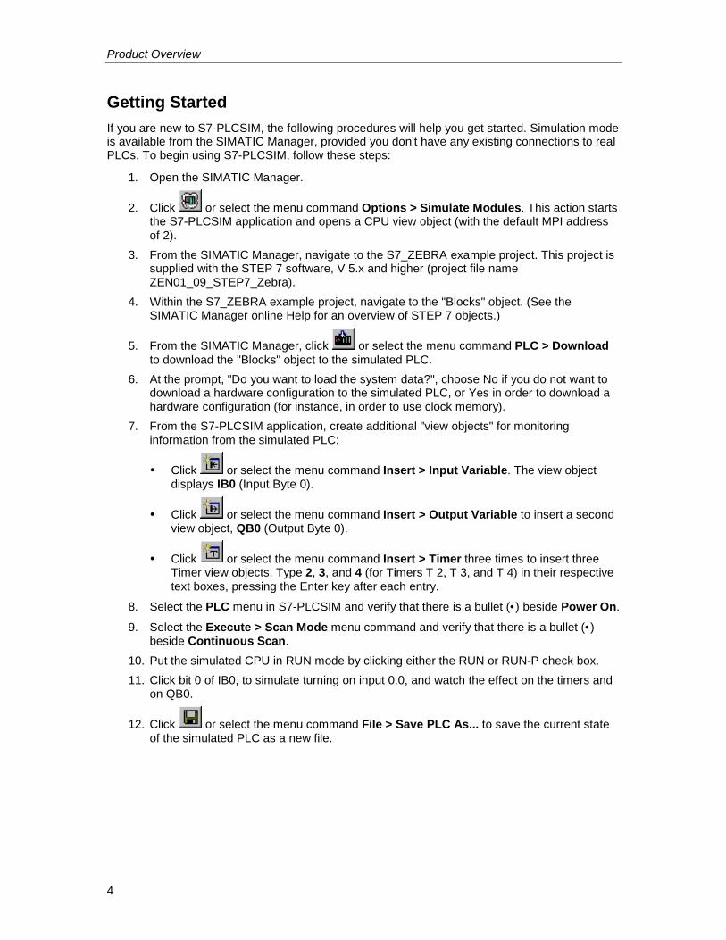
Getting StartedIf you are new to S7-PLCSIM, the following procedures will help you get started. Simulation modeis available from the SIMATIC Manager, provided you don't have any existing connections to realPLCs. To begin using S7-PLCSIM, follow these steps:
1. Open the SIMATIC Manager.
2. Click or select the menu command Options > Simulate Modules. This action startsthe S7-PLCSIM application and opens a CPU view object (with the default MPI addressof 2).
3. From the SIMATIC Manager, navigate to the S7_ZEBRA example project. This project issupplied with the STEP 7 software, V 5.x and higher (project file nameZEN01_09_STEP7_Zebra).
4. Within the S7_ZEBRA example project, navigate to the "Blocks" object. (See theSIMATIC Manager online Help for an overview of STEP 7 objects.)
5. From the SIMATIC Manager, click or select the menu command PLC > Downloadto download the "Blocks" object to the simulated PLC.
6. At the prompt, "Do you want to load the system data?", choose No if you do not want todownload a hardware configuration to the simulated PLC, or Yes in order to download ahardware configuration (for instance, in order to use clock memory).
7. From the S7-PLCSIM application, create additional "view objects" for monitoringinformation from the simulated PLC:
� Click or select the menu command Insert > Input Variable. The view objectdisplays IB0 (Input Byte 0).
� Click or select the menu command Insert > Output Variable to insert a secondview object, QB0 (Output Byte 0).
� Click or select the menu command Insert > Timer three times to insert threeTimer view objects. Type 2, 3, and 4 (for Timers T 2, T 3, and T 4) in their respectivetext boxes, pressing the Enter key after each entry.
8. Select the PLC menu in S7-PLCSIM and verify that there is a bullet (• ) beside Power On.
9. Select the Execute > Scan Mode menu command and verify that there is a bullet (• )beside Continuous Scan.
10. Put the simulated CPU in RUN mode by clicking either the RUN or RUN-P check box.11. Click bit 0 of IB0, to simulate turning on input 0.0, and watch the effect on the timers and
on QB0.
12. Click or select the menu command File > Save PLC As... to save the current stateof the simulated PLC as a new file.
Product Overview
5
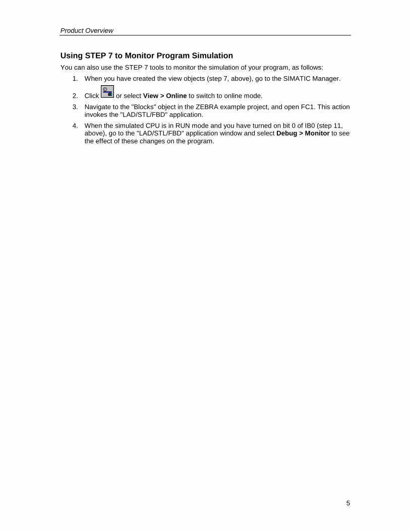
Using STEP 7 to Monitor Program SimulationYou can also use the STEP 7 tools to monitor the simulation of your program, as follows:
1. When you have created the view objects (step 7, above), go to the SIMATIC Manager.
2. Click or select View > Online to switch to online mode.3. Navigate to the "Blocks" object in the ZEBRA example project, and open FC1. This action
invokes the "LAD/STL/FBD" application.4. When the simulated CPU is in RUN mode and you have turned on bit 0 of IB0 (step 11,
above), go to the "LAD/STL/FBD" application window and select Debug > Monitor to seethe effect of these changes on the program.
Product Overview
6
Differences from a Real S7 PLCThe simulated PLC provides the following features which are not available in a real PLC:
� The Pause command halts the simulated CPU and allows you to resume the execution ofthe program at the instruction where the program was halted.
� You can change the operating mode (RUN, RUN-P, and STOP) as you do with a realCPU. Unlike with a real CPU, however, putting the simulated CPU in STOP mode doesnot change the state of the outputs.
� Any change that you make with a view object immediately updates the contents of thememory location. The CPU does not wait until the beginning or end of the scan to updateany changed data.
� Execution control options allow you to select how the CPU runs the program:� Single Scan executes the program for one scan and then waits for you to start the
next scan.� Continuous Scan executes the program like a real PLC: it starts a new scan
immediately after the previous one finishes.� You can allow the timers to run automatically, or you can enter timer values manually.
You can also reset timers globally or individually.� You can manually trigger the interrupt OBs: OB40 to OB47 (hardware interrupt), OB70
(I/O redundancy error), OB72 (CPU redundancy error), OB73 (communicationredundancy error), OB80 (time error), OB82 (diagnostic interrupt), OB83 (insert/removemodule), OB85 (program sequence error), and OB86 (rack failure).
� Process image and peripheral memory: When you make a change to a process inputvalue in a view object, S7-PLCSIM copies it immediately to peripheral memory. This way,when the peripheral input value is written to the process image register at the beginningof the next scan, the desired change is not lost. Correspondingly, when you make achange to a process output value, it is copied immediately to peripheral output memory.
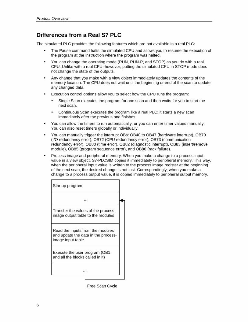
Startup program
Read the inputs from the modulesand update the data in the process-image input table
Transfer the values of the process-image output table to the modules
Execute the user program (OB1and all the blocks called in it)
…
…
Free Scan Cycle
Product Overview
7
S7-PLCSIM also differs from a real PLC in the following ways:� Diagnostic buffers: S7-PLCSIM does not support all of the error messages written to the
diagnostic buffer. For instance, bad batteries in the CPU or EEPROM errors cannot besimulated. However, most I/O and program errors can be simulated.
� A transition in operating mode (such as from RUN to STOP) does not change the I/O to a"safe" state.
� Function modules (FMs) are not supported.� Peer-to-peer communication (such as between two S7-400 CPUs in the same rack) is not
supported.� S7-PLCSIM supports four accumulators like an S7-400 CPU does. For certain special
cases, a program running on S7-PLCSIM with four accumulators can have differentbehavior from the same program running on an S7-300 CPU, which uses only twoaccumulators.
Differences with I/OMost of the CPUs in the S7-300 family autoconfigure I/O: once a module has been inserted into aphysical controller, it is automatically recognized by the CPU. It is not possible to replicate theautoconfiguration feature with a simulated PLC. If you download a program to S7-PLCSIM froman S7-300 CPU that autoconfigures I/O, the system data does not include an I/O configuration.Consequently, when you use S7-PLCSIM with S7-300 programs, if you want to define whichmodules are supposed to be available to the CPU, you must first download a hardwareconfiguration.To download a hardware configuration to S7-PLCSIM, you can create a project for one of the S7-300 CPUs that does not autoconfigure I/O, such as the S7-315-2DP, S7-316-2DP, or S7-318-2.Put a copy of your hardware configuration into this project and download the hardwareconfiguration to S7-PLCSIM. Once you have done this, you can download program blocks fromany of your S7 projects and the I/O will be handled correctly.
Product Overview
8
S7-PLCSIM Main WindowThe main window of S7-PLCSIM includes the workspace, title bar, status bar, window controls,and S7-PLCSIM menus and toolbars.The S7-PLCSIM workspace is where you display different types of view objects to monitor andmodify data in the simulated PLC.
To open the simulated PLC, click on the Simulation On/Off button on the toolbar (menucommand Options > Simulate Modules) in the SIMATIC Manager. S7-PLCSIM starts and loadsa CPU view object for your simulated PLC.You can also create a new simulated PLC, or open one that you have previously saved.
� To create a new PLC for simulation, select the menu command File > New PLC.� To open a previously saved PLC, select the menu command File > Open PLC....
To get familiar with S7-PLCSIM, use the procedures described in Getting Started.
Product Overview
9
CPU Operating ModesRUN-P modeThe CPU runs the program and you can change the program and its parameters. In order to usethe STEP 7 tools for modifying any of the parameters of the program while the program isrunning, you must put the CPU in RUN-P mode. You can still use the "view objects" createdwithin S7-PLCSIM to modify any data used by the program.
RUN modeThe CPU runs the program, by reading the inputs, executing the program, and then updating theoutputs. You cannot download any program or use the STEP 7 tools to change any parameters(such as input values) when the CPU is in RUN mode. You can still use the view objects createdwithin S7-PLCSIM to modify any data used by the program.
STOP modeThe CPU does not run the program. Unlike STOP mode for real CPUs, the outputs are not set topredefined ("safe") values but remain at the state they were in when the CPU changed to STOPmode. You can download programs to the CPU while the CPU is in STOP mode. Changing fromSTOP mode to RUN mode starts execution of the program from the first instruction.The CPU operating modes, the CPU indicators, and the Memory Clear/Reset button are alldisplayed on the CPU view object. You can set the CPU operating mode with the Key SwitchPosition command. You can pause execution of the simulated PLC program when the CPU is inRUN or RUN-P mode.
Product Overview
10
CPU IndicatorsThe CPU view object provides a set of indicators that correspond to the LED indicators on a realCPU:
� SF (system fault) alerts you that the CPU encountered a system error, causing a changein the operating mode.
� DP (distributed peripherals, or remote I/O) indicates the status of communication withdistributed (remote) I/O.
� DC (power supply) indicates whether power to the CPU is on or off.� RUN indicates that the CPU is in RUN mode.� STOP indicates that the CPU is in STOP mode.
Memory AreasYou access data in the S7 PLC by addressing specific areas of memory. These areas performspecific functions:
� PI (peripheral input): provides direct access to the input modules.� I (input): provides access to the process image of the peripheral inputs. These values are
updated by the CPU at the beginning of every CPU scan cycle.� PQ (peripheral output): provides direct access to the output modules. These values are
updated by the CPU at the end of every CPU scan cycle.� Q (output): provides access to the process image of the outputs.� M (bit memory): provides storage for data used within the program.� T (timer): provides storage for timers.� C (counter): provides storage for counters.
You can also access data stored in the data blocks (DBs).
Basic Tasks
11
Basic TasksStarting the SimulationThere are several ways to start S7-PLCSIM:
� From the Windows Start menu, select the menu command Simatic>STEP 7>S7-PLCSIMSimulating Modules.
� From the SIMATIC Manager toolbar, click the Simulation On/Off button or select theOptions > Simulate Modules menu command.
� Create a shortcut to the program file. ([CD]:\Siemens\PLCSIM\s7wsi\s7wsvapx.exe,where [CD] represents the installation drive)
When the Simulation On/Off button is turned on , any new connection goes automatically tothe simulated PLC. Any program that you download goes to the simulated PLC if the MPI addressof the simulated PLC matches that of the STEP 7 project containing the program. If you click theAccessible Nodes button, the Accessible Nodes window shows the node address for thesimulated PLC that you have created.
When the simulation button is turned off , any new connection goes to the real PLC. If youclick the Accessible Nodes button, the Accessible Nodes window shows the network of realPLCs.After you start S7-PLCSIM, you can open a simulated PLC or monitor the simulated program.You can continue PLC simulation until you end the simulation session.NotesSimulation mode is not available if you have any existing connections to real PLCs.You can have only one simulated PLC active at a time.
Basic Tasks
12
Using HelpYou can access the S7-PLCSIM Help through the Help menu or in any of the following ways:
� You can get Help about an item in the S7-PLCSIM window. Click the Help button onthe toolbar, and then click the item.
� You can get help about any dialog box or error message. Click the Help button in thedialog or message box, or press F1.
The Help window provides the following buttons, menu commands, and tabs:
Help ButtonsHide Button / Show ButtonToggles the display of the navigation area (Table of Contents, Index, and Search tabs). Toreduce the overall size of the help window, you can hide the navigation area; when you are readyto search for new topics, click the Show button to restore the navigation area.Back ButtonIf you have examined more than one topic, this button allows you to move back to the previoustopic(s).Print ButtonAllows you to send a selected topic, or an entire book, to any printer that you have installed.
Options Button Menu CommandsHide Tabs / Show Tabs: Toggles the display of the Table of Contents, Index, and Search tabs.To reduce the overall size of the help window, you can hide the tabs; when you are ready tosearch for new topics, you can show the tabs.Back: If you have examined more than one topic, this option allows you to move back to theprevious topic(s).Forward: If you have moved back in the sequence of topics examined, this option allows you tomove forward until you reach the topic that you were viewing when you started moving back.Home: Takes you to the web page that is defined as the home page for the S7-PLCSIM onlinehelp.Stop: Allows you to stop the browser from retrieving any more information pertaining to thecurrent help page. This command is useful if a page contains a great deal of information (forexample, large graphic files) that causes the page to take a long time to display completely.Refresh: Refreshes the display of the current help page.Internet Options: Allows you to define options for Internet browsing.Print: Allows you to send a selected topic, or an entire book, to any printer that you haveinstalled.Search Highlight Off / Search Highlight On: Toggles the display of highlighting for topics thatcontain a term that you have specified in the Search field. The highlighting enables you to seeexactly where in a given topic the term appears.

Basic Tasks
13
Help Browser TabsContents TabChoose this tab to view the table of contents for the help system. Double-click any book icon toexpand it and view the topics that it contains.Index TabChoose this tab to view an alphabetical list of index keywords for the help system.Search TabChoose this tab and type in a term that you wish to find. Then click the List Topics button to seewhether any topics in the help system contain the specified term. Select a topic from the list andclick the Display button to view the topic. By default, the term is highlighted every place that itappears in the topic, to make it easy to locate the term. To toggle highlighting off or on beforedisplaying a topic, use the Options button.
Basic Tasks
14
Opening a Simulated PLCWhen you start S7-PLCSIM, the simulator opens with a new, untitled, simulated PLC. If this isyour first time using S7-PLCSIM, you see only a CPU view object; otherwise, S7-PLCSIMdisplays the view objects from your previous work session.At this point, you have two choices:
� You can begin work in S7-PLCSIM using the new simulated PLC.� You can open a simulated PLC that you have previously saved: use either the File >
Recent Simulation command or the File > Open PLC... command to select theappropriate .PLC file. The work that you did with this PLC (such as downloading aprogram or hardware configuration, or assigning values through a view object) is saved inthe archived simulation, so when you open the simulation, you do not have to repeatthose steps. You can begin work where you left off the last time.
After you decide whether to work with a new or an archived PLC simulation, you can add orchange the view objects displayed in S7-PLCSIM. If a layout is displayed when you openS7-PLCSIM, you can close it. You can use the toolbar or the View and Insert menus to add newview objects. You can use the menu command File > Open Layout to select a different layout ifyou have archived more than one. Changes to your layout do not cause changes to your programinformation; they only affect the way that the information is displayed.
NoteWhen you open a new or archived PLC simulation, any view objects that were displayed inS7-PLCSIM are automatically closed. If you intend to open an archived layout as well as a new orarchived PLC simulation, open the simulated PLC before opening the layout.
What Is the Difference between a .PLC File and a .LAY File?A .PLC file is used to save information about work that you do with a CPU view object (that is, asimulated PLC). It also records changes you make to data: if you assign a value to a memoryarea using any view object, that change is saved in the .PLC file.A .LAY file is used to save the physical layout of your workspace in S7-PLCSIM. If you arrangeyour view objects in a certain order and want to preserve that order for future work sessions, savethe layout before you close S7-PLCSIM. The next time you open S7-PLCSIM, the view objectswill be displayed in that order. (However, if you open a new or archived PLC simulation duringthat work session, S7-PLCSIM automatically closes your layout. If you want to use the samelayout with the simulated PLC that you have opened, just re-open the .LAY file.)

Basic Tasks
15
Opening a LayoutTo open a previously saved layout of S7-PLCSIM view objects, select the menu command File >Open Layout....
A layout is simply an arrangement of view objects. In other words, the .LAY file archives only theposition and selected data format of the view objects in your simulation; the data values that aredisplayed in the view objects are not saved as part of the layout.
When you work in S7-PLCSIM, you can open both a .PLC file and a .LAY file (if you havepreviously saved your simulated PLC and the layout of your view objects). These are not mutuallyexclusive actions; you do not have to choose only one. However, it is more efficient to open thesimulated PLC (.PLC file) before the layout (.LAY file), because any time you open a new orarchived PLC simulation, S7-PLCSIM automatically closes the open layout. You can also save alayout, save a simulated PLC, and close a simulated PLC.
Basic Tasks
16
Selecting Scan Mode OptionsS7-PLCSIM offers you options for running the simulated program:
� Single Scan: The CPU executes one scan and then waits for you to initiate another scan.Each scan consists of the CPU reading the peripheral inputs (PI), executing the program,and then writing the results to the peripheral outputs (PQ). The CPU then waits for you to
run the next scan (using the Execute > Next Scan menu command or ).� Continuous Scan: The CPU executes one complete scan and then starts another scan.
Each scan consists of the CPU reading the peripheral inputs (PI), executing the program,and then writing the results to the peripheral outputs (PQ).
To choose Single Scan mode, click or select the menu command Execute > Scan Mode >Single Scan. Accessing a program one scan at a time allows you to see the changes in eachscan. While a real CPU can execute faster than the editor can display data, the S7-PLCSIMSingle Scan option allows you to "freeze" the state of the program from scan to scan.
To choose Continuous Scan mode, click or select the menu command Execute > ScanMode > Continuous Scan. (The default setting is Continuous Scan.)
Basic Tasks
17
Changing CPU Operating ModesYou can change the operating modes for the CPU. The simulated PLC responds to changes inthe operating mode just like a real PLC. The check boxes on the view object of the simulated PLCshow the current operating mode. To change the operating mode, click the desired checkbox oruse the menu command Execute > Key Switch Position > [mode].The CPU operating modes on the simulated CPU function like the key switch on a real CPU: ifyou use the STEP 7 tools to change the operating mode, or if the CPU automatically changesmode (for example, encounters an error condition that causes the CPU to change from RUN toSTOP), the checkboxes on the simulated CPU view object do not change. The LED indicatorchanges, but not the key switch. This alerts you that the CPU operating mode changed, possiblybecause of some error in the program.
Basic Tasks
18
Monitoring the Simulated ProgramYou can display different types of view objects that allow you to monitor and modify the programrunning in the simulated PLC.The following seven view objects are activated from the Insert menu:
� Input Variable: allows you to access the data stored in the process input (I) memoryarea. The default address is byte 0 (IB0).
� Output Variable: allows you to access the data stored in the process output (Q) memoryarea. The default address is byte 0 (QB0).
� Bit Memory: allows you to access the data stored in the bit memory (M) area. Thedefault address is byte 0 (MB0).
� Timer: allows you to access the timers used by the program. The default timer is T 0.� Counter: allows you to access the counters used by the program. The default counter is
C 0.� Generic: allows you to access any of the memory areas in the simulated CPU, including
the data blocks (DBs) for the program.� Vertical Bits: allows you to see the symbolic or absolute address of each bit and to
monitor and modify data. The vertical bits variable view object can be used to show a bitrepresentation of peripheral input and output variables, process image input and outputvariables, bit memory, and data blocks.
You can also use symbolic addressing to address any of these view objects.The following three view objects are activated from the View menu:
� Accumulators: allows you to display the data in the different accumulators within thesimulated CPU, as well as the status word and address registers. This view objectdisplays four accumulator fields to accommodate the four accumulators of the S7-400CPU. Programs for an S7-300 CPU use only two accumulators.
� Block Registers: allows you to display the contents of the data block address registerswithin the simulated CPU. It also displays the number of the logic block that is currentlybeing executed and the number of the previous logic block, along with the number of theinstruction (step address counter, or SAC) being executed.
� Stacks: allows you to display the data stored in the nesting stack and the master controlrelay (MCR) stack within the simulated PLC.
You can also simultaneously monitor the program in the STEP 7 "LAD/STL/FBD" application:
1. In the SIMATIC Manager, click or select View > Online to switch to online mode.2. Navigate to the "Blocks" object in the S7_ZEBRA example project, and open FC1.3. The "LAD/STL/FBD" application displays the program that is being executed by the
simulated PLC. Use the menu commands to view the status of the instructions.
Basic Tasks
19
Using the Slider ControlThe slider control allows you to simulate values that change gradually or have a specific range,such as analog values. You can use the slider control for the following view objects:
� Input Variable� Output Variable� Bit Memory
You can access the memory area with either a memory address or a symbolic address. Tospecify a slider control for one of the variable view objects, you select a slider formatrepresentation from the Select Numeric Format drop-down list. You also select whether torepresent the values as decimal (positive integers), integer (positive and negative integers), orreal numbers. The selection options are determined by the size of the memory location beingaccessed:
� Byte (B): decimal� Word (W): decimal and integer� Double word (D): decimal, integer, and real
You can use either the mouse or the arrow keys to change the position of the slider controlindicator. Changing the position of the indicator changes the value of the variable stored in thememory location. You can also enter a specific value in the “Value” field.You can also configure a minimum and maximum value for the slider control. Selecting a range ofvalues does not affect the values that can be stored in the variable: the minimum and maximumvalues affect only the values that can be entered or displayed by the slider control. Selecting arange of values provides the following benefits:
� You can simulate a specific range of values, for example, the range of values that wouldbe generated by a specific analog module.
� By limiting the range of values between the minimum and maximum, you can providebetter resolution for entering data with the slider. You can always enter an exact value inthe Value field of the view object.
To select a minimum value for the slider, select Min from the Display Value, Min, or Max drop-down list of the view object. Then, enter the numeric value for the minimum in the Min field.To select a maximum value for the slider, select Max from the Display Value, Min, or Max drop-down list of the view object. Then, enter the numeric value for the maximum in the Max field.
Basic Tasks
20
Using S7-PLCSIM to Debug Your ProgramS7-PLCSIM provides the following features to help you debug your program:
� The Pause command halts the simulated CPU immediately and allows you to resume theexecution of the program at the instruction where the program was halted.
� Any change that you make with a view object immediately updates the contents of thememory location. The CPU does not wait until the beginning or end of the scan to updateany changed data.
� Execution control options allow you to select how the CPU runs the program:� Single Scan executes the program for one scan and then waits for you to start the
next scan.� Continuous Scan executes the program like a real PLC; it starts a new scan
immediately after the previous one finishes.
Basic Tasks
21
Using Interrupt OBs in Your ProgramYou can use S7-PLCSIM to test how your program handles different interrupt OBs. S7-PLCSIMsupports the following:
� OB40 to OB47 (hardware interrupt)� OB70 (I/O redundancy error) {417-H systems only}� OB72 (CPU redundancy error) {417-H systems only}� OB73 (communication redundancy error) {417-H systems only}� OB80 (time error)� OB82 (diagnostic interrupt)� OB83 (insert/remove module)� OB85 (priority class error)� OB86 (rack failure)
Use the menu command Execute > Trigger Error OB... to select a specific OB, and enter theheader information in the dialog box. When you click the "OK" or "Apply" button, the simulatedPLC generates the appropriate event and runs the program in the associated OB. The OBs thatare available to be triggered from the Trigger Error OB menu depend on the I/O configuration forthe simulated PLC.
Input/Output ConsiderationsIf your project matches either of the following descriptions, you must make modifications anddownload your modified hardware configuration to S7-PLCSIM:
� An S7-300 project with any CPU other than the CPU 315-2 DP, CPU 316-2 DP, or CPU318-2
� An S7-400 project that uses DP I/O with a CP instead of using a CPU model thatexplicitly supports DP I/O
In order to simulate interrupt OBs, you must download a hardware configuration that containsyour I/O. For some cases your I/O is automatically included in the system data that STEP 7downloads to S7-PLCSIM; in other cases, you must modify the configuration to one that does.S7-300 CPUsS7-300 CPUs such as the S7-315-2DP, S7-316-2DP, and S7-318-2 download an I/Oconfiguration; other S7-300 CPUs autoconfigure the I/O to match the physical I/O installed in therack. Projects already configured for one of the CPUs named above do not require modificationsto the hardware configuration.For other CPUs, you must copy your hardware configuration and put the data into a project for aCPU that does not autoconfigure I/O, namely an S7-315-2DP, S7-316-2DP, or S7-318-2 project.When you download the I/O information from the project, you can simulate interrupt OBs in S7-PLCSIM (and S7-PLCSIM is also able to detect any I/O referencing errors that your program maycontain).S7-400 CPUsIf you use a CP with PROFIBUS-DP I/O, you cannot download this I/O configuration and use it tosimulate an interrupt OB in S7-PLCSIM. However, you can copy your I/O configuration into asecond project and replace the S7-400 CPU with an S7-400 CPU model (such as the CPU 416-DP) that explicitly supports DP. Once you download the hardware configuration from this secondproject to S7-PLCSIM, you can simulate interrupt OBs and detect I/O referencing errors.

Basic Tasks
22
Modifying Your Hardware ConfigurationIn order to simulate the handling of interrupt OBs in your program, your I/O configuration mustuse a CPU 315-2 DP, CPU 316-2 DP, CPU 318-2, or an S7-400 CPU that directly supports DPI/O. S7-PLCSIM supports only one DP master system; you cannot use hardware configurationswith more than one DP master system. If your CPU is not of the type mentioned above, you canuse the following procedure to create and modify a copy of your hardware configuration:
1. Insert a new SIMATIC station to hold the modified configuration that you are going tocreate. Name it something descriptive, such as SIM_IO.
2. Navigate to your station.3. Open the Hardware Configuration of your station.4. Copy the central rack from your Hardware Configuration.
WarningBe certain only to copy, not cut, from the configuration of your original project to theconfiguration of the SIM_IO project. If you cut items from your original configuration, yourHardware Configuration will no longer work in real field applications.
5. Leaving the Hardware Configuration of your station open, navigate back to the SIM_IOstation and open its Hardware Configuration.
6. Paste the central rack from your original configuration into the SIM_IO configuration.7. In the SIM_IO configuration, edit the rack to replace the existing CPU.
� If the existing CPU is an S7-300, replace it with a CPU 315-2 DP, CPU 316-2 DP, orCPU 318-2.
� If the existing CPU is an S7-400, replace it with a CPU that directly supports DP.(The extension "DP" should appear in the name of the model that you select.)
NoteWhen you insert a new CPU in the central rack, the STEP 7 hardware configurationsoftware issues a series of messages prompting you to assign a network. If your originalproject was not networked, answer "No" to these prompts. The STEP 7 hardwareconfiguration software displays the message "Cannot assign a PROFIBUS network to theDP master." Because you do not need a PROFIBUS network, this message is not aproblem.
8. If your configuration previously used a CP for DP communications, delete the CP fromthe SIM_IO configuration. The CP is not necessary after you put a DP CPU into theconfiguration.
9. If you have expansion racks or PROFIBUS slaves in your original configuration, copythem into the SIM_IO configuration.
10. Carefully check the addresses assigned by STEP 7 to the modules in the SIM_IOconfiguration and make any necessary changes.
11. Save and close the SIM_IO configuration.12. Close the original configuration.
After you make the required modifications, you can download the modified configuration to S7-PLCSIM.
Basic Tasks
23
Downloading the Modified ConfigurationAfter you create a modified I/O configuration to be used with S7-PLCSIM, you can download theresulting system data.
1. In the SIMATIC Manager window, navigate to the SIM_IO project and open the blocksobject. A System Data object and an OB1 block are displayed.
2. Delete the OB1 block object from the SIM_IO project. This ensures that you cannotunintentionally download an empty OB1 to S7-PLCSIM from the SIM_IO project.
3. Download your Hardware Configuration to S7-PLCSIM.
NoteIt does not matter whether you download your program blocks before or after youdownload the SIM_IO Hardware Configuration. However, if you do download programblocks after downloading the SIM_IO Hardware Configuration, be sure that you answer"No" to the prompt, "Do you want to load the system data?" If you inadvertently load thesystem data from your original project, the SIM_IO Hardware Configuration is overwritten.
Resetting the CPU MemoryTo reset the memory of the simulated CPU, select the menu command PLC > Clear/Reset, orclick the MRES button on the CPU view object. This action resets the memory areas and deletesthe program blocks and hardware configuration.When you perform a memory clear/reset, the CPU automatically goes to STOP mode.
Resetting TimersThe Reset Timers dialog box allows you to reset any or all of the timers used in your program totheir default values. Selecting "All Timers" resets all of the timers in the program; you can alsoselect specific timers to reset.
To reset all of the timers in your program, use the Reset Timers toolbar button.
To reset an individual timer, use the Reset Timers button on the timer view object for thespecific timer.
Basic Tasks
24
Using Symbolic AddressingTo use symbolic addressing in your simulated program:
1. Select the menu command Tools > Options > Attach Symbols.... This menu commandinvokes a dialog box.
2. Browse to the STEP 7 symbol table to be referenced.3. Click the OK button.4. Create view objects for variables that you want to address symbolically.5. To turn on symbols for all view objects, select the menu command Tools > Options >
Show Symbols. To hide the symbols, select the command again.For the Vertical Bits view object, bit values are displayed vertically, and the symbolic or absoluteaddress is displayed beside each bit. For all other view objects, symbol tooltips are available forthe address fields. Point to a field with the mouse to see its symbolic address and comment(separated by a colon) in a tooltip box.
Configuring an MPI AddressUse the MPI Address dialog box (menu command PLC > MPI Address...) to configure thesimulated PLC for a specific network node address. The new address is stored with theconfiguration of the simulated PLC when you use the Save PLC or Save PLC As... menucommands.Ensure that the node address for the offline program matches the node address for the programin the simulated PLC.
When the Simulation On/Off button on the SIMATIC Manager toolbar is turned on, clickingthe Accessible Nodes button shows you that the simulated PLC that is currently open.NoteYou cannot change the node address for the simulated PLC while you are using STEP 7applications to monitor the program. Close these applications before changing the node address.
Basic Tasks
25
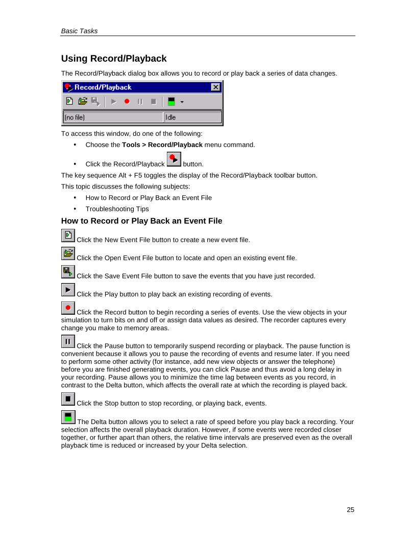
Using Record/PlaybackThe Record/Playback dialog box allows you to record or play back a series of data changes.
To access this window, do one of the following:� Choose the Tools > Record/Playback menu command.
� Click the Record/Playback button.The key sequence Alt + F5 toggles the display of the Record/Playback toolbar button.This topic discusses the following subjects:
� How to Record or Play Back an Event File� Troubleshooting Tips
How to Record or Play Back an Event File
Click the New Event File button to create a new event file.
Click the Open Event File button to locate and open an existing event file.
Click the Save Event File button to save the events that you have just recorded.
Click the Play button to play back an existing recording of events.
Click the Record button to begin recording a series of events. Use the view objects in yoursimulation to turn bits on and off or assign data values as desired. The recorder captures everychange you make to memory areas.
Click the Pause button to temporarily suspend recording or playback. The pause function isconvenient because it allows you to pause the recording of events and resume later. If you needto perform some other activity (for instance, add new view objects or answer the telephone)before you are finished generating events, you can click Pause and thus avoid a long delay inyour recording. Pause allows you to minimize the time lag between events as you record, incontrast to the Delta button, which affects the overall rate at which the recording is played back.
Click the Stop button to stop recording, or playing back, events.
The Delta button allows you to select a rate of speed before you play back a recording. Yourselection affects the overall playback duration. However, if some events were recorded closertogether, or further apart than others, the relative time intervals are preserved even as the overallplayback time is reduced or increased by your Delta selection.
Basic Tasks
26
There are two ways for you to confirm that you are successfully recording or playing back events:� Check the status bar of the Record/Playback dialog box to see whether it is in Recording,
Playing, or Idle mode.� Watch the title bar of the Record/Playback dialog box. It should display a numeric value
that increments each time you record or play back an event.If you are satisfied with your recording, remember to save it by using the Save Event File buttonbefore you close S7-PLCSIM.
Troubleshooting TipsProblem SolutionI tried to recordevents, but when Iplayed them back,nothing happened.
Change the mode of S7-PLCSIM from STOP to RUN.You can record events in STOP mode provided that you had previouslybeen recording in RUN mode. All events recorded in STOP mode have aDelta value of zero. Therefore, when you play back the recording, all theevents that you recorded during a single scan are displayed in such rapidsuccession that they appear to occur simultaneously.
The Play buttonis de-activated and Icannot play back arecording.
You must have an open event file before you can play back the recordingof the events. Use the Open Event File button to select and open an eventfile.
I recorded a series ofevents and thenclosed S7-PLCSIM.The next time Iopened S7-PLCSIM,I could not find theevents.
If you close S7-PLCSIM without saving the recorded events in an event
file, your work is lost. Use the Save Event File button to save yourwork before you close S7-PLCSIM.
I recorded a series ofevents, but when Itried to play themback, nothinghappened.
Check the status bar of the Record/Playback dialog box to see what modeit is in. If it says Playing, watch the title bar to see when a numeric valueappears. When events are played back, a counter in the title bar keepstrack of how many have been played back. Note that if you start arecording but do not promptly begin to trigger events, the recordercaptures the time lag. When you play back the recording, the first eventwill take an equally long time to occur. You can examine the event file toverify that in fact, your events have been properly recorded. You can
adjust the playback speed of the recording by using the Delta button.
I cannot rememberwhich event filecontains thesequence of eventsthat I want to playback.
You can use long, descriptive file names to help differentiate your eventfiles. If necessary, you can use a text editor to examine your files andlocate the one with the correct sequence. The default storage location forevent files is C:\Siemens\Step7\PLCSIM\S7EVENTS. However, if youupgraded from version 3.0 or 4.0 of S7-PLCSIM, the default storagelocation is C:\Siemens\STEP7\S7wsi\S7EVENTS.
Basic Tasks
27
Troubleshooting Tips, continued
Problem SolutionI changed a singlebit, but when I playedback my recording,the entire bytechanged.
If an Input Variable, Output Variable, Bit Memory, Generic Variable, orVertical Bits View Object shows only one bit (e.g., Q0.0, Bits), a bit changeis recorded correctly as only a change in that particular bit. However, if theview object displays all eight bits (e.g., QB0, Bits), a change to a single bitis recorded as a change in byte value instead of a change in that bit only.Consequently, it becomes possible that during playback of the recording,other bits within the byte could be represented as changing (for instance,process flags or Boolean inputs), when in fact they would not be affectedduring operation of a real PLC.
I am trying to recordevents in Single Scan
mode but therecorder does notfunction as I wouldexpect.
When recording events with the CPU view object in Single Scan mode,note the following:
� You cannot start a recording in Single Scan mode unless you click
the Next Scan button to increment the scan count. The firstevent in your recording must have a Delta value of 1 or higher.The Delta value is based on the number of scan cycles that haveoccurred since the previous event (which in this case was whenyou clicked the Record button). However, if you are beginning therecording in Single Scan mode, no scan cycles have elapsed. Youmust increment the scan.
� When you record events in Single Scan mode, they have a Deltavalue of zero (because they are all occurring within the samescan). Therefore, when you play back the recording, all the eventsthat you recorded during a single scan are displayed in such rapidsequence that they appear to occur simultaneously. To provide adiscernable time lag between events, you would have to click theNext Scan button or switch between Continuous Scan mode andSingle Scan mode for each event.
My event file containsGerman mnemonicseven though that isnot my selection inSTEP 7.
Events are recorded with German mnemonics in S7-PLCSIM regardless ofyour STEP 7 selection. You can disregard this phenomenon.
Basic Tasks
28
Monitoring the Scan CycleThe Scan Cycle Monitoring dialog box allows you to enable or disable scan cycle monitoring(watchdog timer) and set the maximum scan cycle monitoring time for the simulation. Themaximum scan cycle time is the maximum time the process is allowed to take for one full scancycle of the S7 user program in the OB1 and update of the relevant I/O. If this time is exceeded,the simulated PLC goes into STOP mode.Because program execution may be significantly slower in S7-PLCSIM than with an actual CPU(especially when other applications are running at higher priority), you can experience annoyingtimeouts. This dialog box makes it possible for you to disable or extend the scan cycle monitoringwithout modifying the program for the target PLC.Note that this dialog box does not reflect the monitoring time set in the hardware configuration,and any changes affect the simulation only.If "Enable Scan Cycle Monitoring" is selected, you can set the monitoring time to any valuebetween 1 second (1000 ms) and 1 minute (60000 ms), inclusive. The default scan cyclemonitoring time is 20000 ms.
Saving a LayoutTo save the current layout of S7-PLCSIM view objects, select the menu command File > SaveLayout. A layout is simply an arrangement of view objects. In other words, the .LAY file archivesonly the position and selected data format of the view objects in your simulation; the data valuesthat are displayed in the view objects are not saved as part of the layout.
You can save both the layout (.LAY file) and the PLC simulation (.PLC file) when you work. Theyare not mutually exclusive. For information about what is archived if you save a PLC simulation(.PLC file), see Saving a Simulated PLC.
Basic Tasks
29
Saving a Simulated PLCYou can store the current state of the simulated PLC in one of the following ways:
� Use the menu command File > Save PLC to archive the configuration of the PLC to thecurrent file name.
� Use the menu command File > Save PLC As... to archive the configuration of the PLC toa new file.
The following elements are saved when you save the PLC:� Program� Hardware configuration� The checkbox selection (key switch position) for the operating mode indicated on the
CPU view object: namely, RUN-P, RUN, or STOP� Execution control option (continuous scan, single scan)� The status of the I/O� Timer values (T memory)� Symbolic addresses� Power on/off setting
When you open a simulated PLC, whether it is a new PLC simulation or an archived PLCsimulation, the simulated PLC is in STOP mode.If you archived a simulated PLC in RUN or RUN-P mode, when you open the archive, thecheckbox of the CPU view object indicates your selection, but the CPU indicators show that theactual mode of the simulated PLC is STOP mode. To restore the simulated PLC to RUN or RUN-P mode, you must use the checkboxes in the CPU view object or the Execute > Key SwitchPosition command to cycle the simulated PLC to STOP mode and then back to RUN or RUN-Pmode.If you have attached symbols, when you save the simulated PLC, the symbolic addresses aresaved. However, by default when you open the archived PLC simulation, symbolic addresses arenot displayed. To display symbolic addresses, use the Tools > Options > Show Symbolscommand.To save the configuration of the view objects, use the File > Save Layout menu command.Saving a simulated PLC does not close the simulated PLC.
Basic Tasks
30
Closing a Simulated PLCUse the menu command File > Close PLC to end the simulation of the program. This commandcloses the CPU view object and all opened views..Closing a simulated program can result in errors in applications which are currently connected tothe simulator. Closing the simulated PLC does not end the simulation session. You can either exitS7-PLCSIM, or open another simulated PLC.
Ending the Simulation SessionAfter saving any simulated PLC or layout configuration, follow these steps to exit the S7-PLCSIMapplication:
1. Close any STEP 7 applications involved in the monitoring of the simulation.2. Select the menu command File > Exit.
Exiting S7-PLCSIM, like closing a simulated PLC, can result in errors in applications which arecurrently connected to the simulator.
View Objects
31
View ObjectsS7-PLCSIM View ObjectsS7-PLCSIM provides several view objects that allow you to monitor and modify variouscomponents of the simulated PLC. These view objects are:
� CPU View Object� ACCUs & Status Word View Object� Block Regs View Object� Stacks View Object� Input Variable View Object� Output Variable View Object� Bit Memory View Object� Timers View Object� Counters View Object� Generic Variable View Object� Vertical Bits Variable View Object
You can use symbolic addressing with view objects. If you do, tooltips are available for all viewobject fields that have symbols assigned to them. You can point to a view object field with themouse to see its symbolic address and comment (separated by a colon) in a tooltip box.
View Objects
32
CPU View ObjectThis view object is present by default when you open a new simulation. It allows you to view thestatus and change the operating mode of the simulated CPU.The operating modes on the CPU view object function like the key switch on a real CPU: if youuse the STEP 7 tools to change the operating mode, or if the CPU automatically changes mode(for example, encounters an error condition that causes the CPU to change from RUN to STOP),the RUN/STOP indicators change, but not the key switch. This alerts you that the CPU changedoperating mode, possibly because of some error in the program.The MRES button allows you to reset the memory and to delete the blocks and the hardwareconfiguration of the simulated PLC.
ACCUs & Status Word View ObjectTo add this view object to a simulation, do one of the following:
� Choose the menu command View > Accumulators
� Click CPU Accumulators buttonThis view object allows you to monitor the information that the CPU uses to execute the program:
� Accumulators: allows you to monitor the contents of the CPU accumulators. The viewobject displays four accumulator fields to accommodate the S7-400 CPU; programs forthe S7-300 CPU use only two accumulators.
� Status word: allows you to monitor the bits of the status word.� Address registers: allows you to monitor the contents of the two address registers (AR1
and AR2). These address registers are used for the indirect addressing of data.
Block Regs View ObjectTo add this view object to a simulation, do one of the following:
� Choose the menu command View > Block Registers
� Click the Block Registers buttonThis view object allows you to monitor the contents of the data block address registers (DB1 andDB2). This view object also displays the number of the current logic block and the previous logicblock, along with the number of the instruction (step address counter, or SAC) for each block.
Stacks View ObjectTo add this view object to a simulation, do one of the following:
� Choose the menu command View > Stacks
� Click the Nesting Stacks buttonThis view object allows you to monitor information stored in the following stacks of the CPU:
� The nesting stack stores up to seven entries. For each entry, the nesting stack stores thestates of the RLO and OR bits of the status word. An entry in the nesting stack is madefor each instruction that starts a new logic string. These instructions are: And (A), AndNot (AN), Or (O), Or Not (ON), Exclusive Or (X), and Exclusive Or Not (XN).
� The MCR stack stores up to eight levels of nesting for a master control relay (MCR).Each level shows the status of the RLO bit for an MCR instruction, which begins an MCRarea.
View Objects
33
Input Variable View ObjectTo add this view object to a simulation, do one of the following:
� Choose the menu command Insert > Input Variable
� Click on the Insert Input Variable buttonThis view object allows you to monitor and modify the following data:
� Peripheral (external) input variables: you can access the peripheral input (PI) memoryareas of the CPU.
� Process-image input variables: you can access the input (I) memory areas of the CPU.The CPU overwrites the I memory with the PI memory at the beginning of every scan. Ifyou change an I memory value, the simulator immediately copies the changed value tothe peripheral area. This way, the desired change is not lost when the peripheral valueoverwrites the process input value on the next scan.
The CPU reacts immediately to any changes made with this view object. (Any modifications madewith a STEP 7 variable table take effect at the proper time in the CPU scan: inputs are read at thebeginning of the scan, and outputs are written at the end.)You can choose the numeric data format for the input variable and you can also use symbolicaddressing if you have attached symbols. You can also view input variables with a Vertical BitsView Object.
Output Variable View ObjectTo add this view object to a simulation, do one of the following:
� Choose the menu command Insert > Output Variable
� Click the Insert Output Variable buttonThis view object allows you to monitor and modify the following data:
� Peripheral (external) output variables: you can access the peripheral output (PQ) memoryareas of the CPU.
� Process-image output variables: you can access the output (Q) memory areas of theCPU. During the scan cycle, the program calculates output values and places them in theprocess-image output table. At the end of the scan cycle, the operating system reads thecalculated output values from this table and sends them to the process outputs. Theprocess-image output table maps the first 512 bytes (CPU-dependent) of the peripheraloutput memory.
The CPU reacts immediately to any changes made with this view object. (Any modifications madewith a STEP 7 variable table take effect at the proper time in the CPU scan: inputs are read at thebeginning of the scan, and outputs are written at the end.)You can choose the numeric data format for the output variable and you can also use symbolicaddressing if you have attached symbols. You can also view input variables with a Vertical BitsView Object.
View Objects
34
Bit Memory View ObjectTo access this view object, do one of the following:
� Choose the menu command Insert > Bit Memory
� Click on the Insert Bit Memory buttonThis view object allows you to monitor and modify bit memory: you can access the variablesstored in the bit memory (M) area of the CPU.The bit memory (M) area provides storage for interim results calculated in the program. Youdesignate what data format to use to access the data.You can choose the numeric data format for the bit memory and you can also use symbolicaddressing if you have attached symbols. You can also view bit memory with a Vertical Bits ViewObject.
Timer View ObjectTo add this view object to a simulation, do one of the following:
� Choose the menu command Insert > Timer
� Click the Insert Timer buttonThis view object allows you to monitor and modify the timers used by your program. The timerview object displays the name of the timer, the actual timer value, and the time base.
NoteIf you change the time base, the actual timer value changes also, while the displayed valueremains the same. This is because the actual timer value is the product of the displayed valueand the time base. For example, if the value of timer T 0 is 600 and the time base is 10ms, thisrepresents a timer of 6 seconds. If you change the time base to 100ms, then the actual timervalue becomes 60 seconds. (600 * 100ms = 60 seconds)
To reset all of the timers in your program, use the Reset Timers toolbar button.
To reset an individual timer, use the Reset Timers button on the view object for that timer.
You can use symbolic addressing if you have attached symbols. You can also configure thetimers to be under either automatic or manual control from commands on the Execute menu, .
Counter View ObjectTo add this view object to a simulation, do one of the following:
� Choose the menu command Insert > Counter
� Click the Insert Counter (or in German mnemonics) buttonThis view object allows you to monitor and modify the counters used by your program. It openswith a default memory location of C 0.You can choose the numeric data format for the counter and you can also use symbolicaddressing if you have attached symbols.
View Objects
35
Generic Variable View ObjectTo add this view object to a simulation, do one of the following:
� Choose the menu command Insert > Generic
� Click the Insert Generic Variable buttonThis view object allows you to monitor and modify the following data:
� Peripheral (external) input and output variables: you can access the peripheral input (PI)and peripheral output (PQ) memory areas of the CPU.
� Process-image input and output variables: you can access the input (I) and output (Q)memory areas of the CPU. The CPU overwrites the I memory with the PI memory at thebeginning of every scan. If you change an I memory value, the simulator immediatelycopies the changed value to the peripheral area. This way, the desired change is not lostwhen the peripheral value overwrites the process input value on the next scan.
� Bit memory: you can access the variables stored in the bit memory (M) area of the CPU.� Timers and counters: you can access the timers and counters used by the program.� Data blocks: you can access the data stored in the data blocks of the program, for
example, DB1.DBX 0.0 or DB1.DBW 0.The CPU reacts immediately to any changes made with this view object. Any modifications madewith a STEP 7 variable table take effect at the proper time in the CPU scan; inputs are read at thebeginning of the scan, and outputs are written at the end.You can choose the numeric data format for the generic variable and you can also use symbolicaddressing if you have attached symbols.

View Objects
36
Vertical Bits Variable View ObjectTo add this view object to a simulation, do one of the following:
� Choose the menu command Insert > Vertical Bits� Click the Insert Vertical Bits button
The Vertical Bits view object allows you to see the symbolic or absolute address of each bit andto monitor and modify the following data:
� Peripheral (external) input and output variables: you can access the peripheral input (PI)and peripheral output (PQ) memory areas of the CPU.
� Process-image input and output variables: you can access the input (I) and output (Q)memory areas of the CPU. The CPU overwrites the I memory with the PI memory at thebeginning of every scan. If you change an I memory value, the simulator immediatelycopies the changed value to the peripheral area. This way, the desired change is not lostwhen the peripheral value overwrites the process input value on the next scan.
� Bit memory: you can access the variables stored in the bit memory (M) area of the CPU.� Data blocks: you can access the data stored in the data blocks of the program.
The CPU reacts immediately to any changes made with this view object. Any modifications madewith a STEP 7 variable table take effect at the proper time in the CPU scan; inputs are read at thebeginning of the scan, and outputs are written at the end. You can use symbolic addressing if youhave attached symbols for variables represented with a Vertical View Object.
Error and Interrupt OBs
37
Error and Interrupt OBsOverviewS7-PLCSIM supports the following interrupt and error OBs:
� OB40 to OB47 (hardware interrupt)� OB70 (I/O redundancy error) {417-H systems only}� OB72 (CPU redundancy error) {417-H systems only}� OB73 (communication redundancy error) {417-H systems only}� OB80 (time error)� OB82 (diagnostic interrupt)� OB83 (insert/remove module)� OB85 (priority class error)� OB86 (rack failure)
Error and Interrupt OBs
38
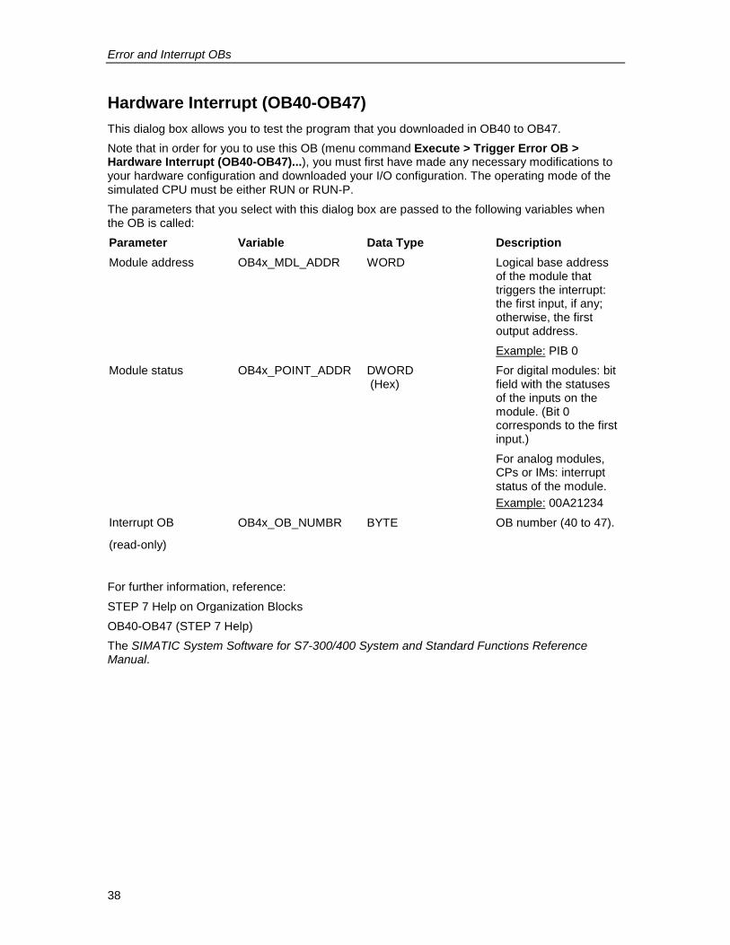
Hardware Interrupt (OB40-OB47)This dialog box allows you to test the program that you downloaded in OB40 to OB47.Note that in order for you to use this OB (menu command Execute > Trigger Error OB >Hardware Interrupt (OB40-OB47)...), you must first have made any necessary modifications toyour hardware configuration and downloaded your I/O configuration. The operating mode of thesimulated CPU must be either RUN or RUN-P.The parameters that you select with this dialog box are passed to the following variables whenthe OB is called:Parameter Variable Data Type DescriptionModule address OB4x_MDL_ADDR WORD Logical base address
of the module thattriggers the interrupt:the first input, if any;otherwise, the firstoutput address.Example: PIB 0
Module status OB4x_POINT_ADDR DWORD (Hex)
For digital modules: bitfield with the statusesof the inputs on themodule. (Bit 0corresponds to the firstinput.)For analog modules,CPs or IMs: interruptstatus of the module.Example: 00A21234
Interrupt OB
(read-only)
OB4x_OB_NUMBR BYTE OB number (40 to 47).
For further information, reference:STEP 7 Help on Organization BlocksOB40-OB47 (STEP 7 Help)The SIMATIC System Software for S7-300/400 System and Standard Functions ReferenceManual.

Error and Interrupt OBs
39
I/O Redundancy Error (OB70)This dialog box allows you to test the loss of redundancy of PROFIBUS-DP and can only be usedwith H CPUs.Note that in order for you to use this OB (menu command Execute > Trigger Error OB > I/ORedundancy Error (OB70)...), you must first have made any necessary modifications to yourhardware configuration and downloaded your I/O configuration.The parameters that you select with this dialog box are passed to the following variables whenthe OB is called:Parameter(Input/Output)
Variable Data Type Description
Error Event Class OB70_EV_CLASS BYTE Event class and IDs:* B#16#72: evententering state* B#16#73: eventleaving state
Error Code OB70_FLT_ID BYTE Error code (possiblevalues):* B#16#A2* B#16#A3
You must also enter values for DP Master Base Address, DP Master System ID, DP Slave BaseAddress, and DP Station Number. Each field needs to match the value that was assigned in theSTEP 7 hardware configuration of the project that you are simulating.The DP Slave Base Address, DP Station Number, and the Input/Output selection are onlyavailable for Error Code 0xA3.For further information, reference:STEP 7 Help on Organization BlocksOB70 (STEP 7 Help)The SIMATIC System Software for S7-300/400 System and Standard Functions ReferenceManual
Error and Interrupt OBs
40
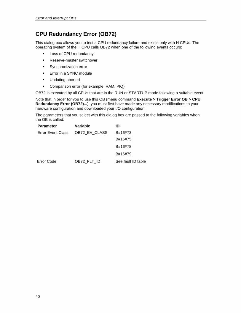
CPU Redundancy Error (OB72)This dialog box allows you to test a CPU redundancy failure and exists only with H CPUs. Theoperating system of the H CPU calls OB72 when one of the following events occurs:
� Loss of CPU redundancy� Reserve-master switchover� Synchronization error� Error in a SYNC module� Updating aborted� Comparison error (for example, RAM, PIQ)
OB72 is executed by all CPUs that are in the RUN or STARTUP mode following a suitable event.Note that in order for you to use this OB (menu command Execute > Trigger Error OB > CPURedundancy Error (OB72)...), you must first have made any necessary modifications to yourhardware configuration and downloaded your I/O configuration.The parameters that you select with this dialog box are passed to the following variables whenthe OB is called:Parameter Variable IDError Event Class OB72_EV_CLASS B#16#73
B#16#75
B#16#78
B#16#79
Error Code OB72_FLT_ID See fault ID table
Error and Interrupt OBs
41
OB72 Fault Ids (Error Codes)The error code in OB72_FLT_ID indicates which event occurred that caused the OB72 call:
OB72_FLT_ID Start Event of OB72B#16#01 Loss of redundancy (1 of 2) due to a CPU failureB#16#02 Loss of redundancy (1 of 2) due to STOP on the reserve triggered by userB#16#03 H system (1 of 2) changed to redundant modeB#16#20 Error in RAM comparisonB#16#21 Error comparing process image output valueB#16#22 Error comparing memory bits, timers, or countersB#16#23 Different operating system data recognizedB#16#31 Standby-master switchover due to master failureB#16#33 Standby-master switchover due to operator interventionB#16#34 Standby-master switchover due to sync module connection problemB#16#35 Standby-master switchover triggered by 90 "H_CTRL"B#16#40 Synchronization error in user program due to elapsed wait timeB#16#41 Synchronization error in user program due to waiting at different
synchronization pointsB#16#42 Synchronization error in operating system due to waiting at different
synchronization pointsB#16#43 Synchronization error in operating system due to elapsed wait timeB#16#44 Synchronization error in operating system due to wrong dataB#16#50 No SYNC moduleB#16#51 Modification at SYNC module without Power OnB#16#52 SYNC module removed/insertedB#16#53 Modification at SYNC module without resetB#16#54 SYNC module: rack number assigned twiceB#16#55 SYNC module error/eliminatedB#16#56 Illegal rack number set on the SYNC moduleB#16#C1 Updating abortedB#16#C2 Abort of update attempt because a monitoring time was exceeded during the
n-th attempt (1 <= n <= maximum possible number of update attempts afteran abort due to the monitoring time being exceeded)
For further information, reference:STEP 7 Help on Organization BlocksOB72 (STEP 7 Help)The SIMATIC System Software for S7-300/400 System and Standard Functions ReferenceManual
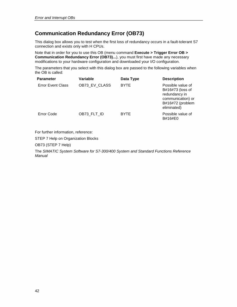
Error and Interrupt OBs
42
Communication Redundancy Error (OB73)This dialog box allows you to test when the first loss of redundancy occurs in a fault-tolerant S7connection and exists only with H CPUs.Note that in order for you to use this OB (menu command Execute > Trigger Error OB >Communication Redundancy Error (OB73)...), you must first have made any necessarymodifications to your hardware configuration and downloaded your I/O configuration.The parameters that you select with this dialog box are passed to the following variables whenthe OB is called:Parameter Variable Data Type Description Error Event Class OB73_EV_CLASS BYTE Possible value of
B#16#73 (loss ofredundancy incommunication) orB#16#72 (problemeliminated)
Error Code OB73_FLT_ID BYTE Possible value ofB#16#E0
For further information, reference:STEP 7 Help on Organization BlocksOB73 (STEP 7 Help)The SIMATIC System Software for S7-300/400 System and Standard Functions ReferenceManual
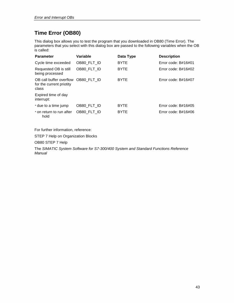
Error and Interrupt OBs
43
Time Error (OB80)This dialog box allows you to test the program that you downloaded in OB80 (Time Error). Theparameters that you select with this dialog box are passed to the following variables when the OBis called:Parameter Variable Data Type DescriptionCycle time exceeded OB80_FLT_ID BYTE Error code: B#16#01Requested OB is stillbeing processed
OB80_FLT_ID BYTE Error code: B#16#02
OB call buffer overflowfor the current priotityclass
OB80_FLT_ID BYTE Error code: B#16#07
Expired time of dayinterrupt:* due to a time jump OB80_FLT_ID BYTE Error code: B#16#05* on return to run after
holdOB80_FLT_ID BYTE Error code: B#16#06
For further information, reference:STEP 7 Help on Organization BlocksOB80 STEP 7 HelpThe SIMATIC System Software for S7-300/400 System and Standard Functions ReferenceManual
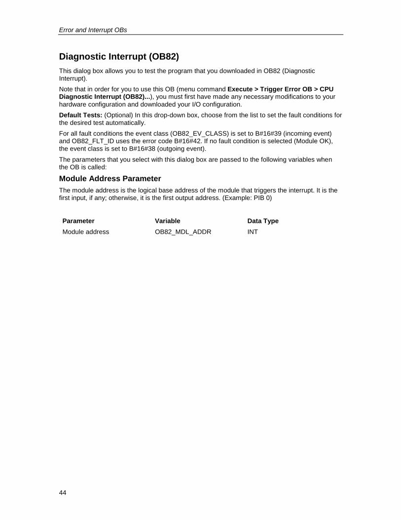
Error and Interrupt OBs
44
Diagnostic Interrupt (OB82)This dialog box allows you to test the program that you downloaded in OB82 (DiagnosticInterrupt).Note that in order for you to use this OB (menu command Execute > Trigger Error OB > CPUDiagnostic Interrupt (OB82)...), you must first have made any necessary modifications to yourhardware configuration and downloaded your I/O configuration.Default Tests: (Optional) In this drop-down box, choose from the list to set the fault conditions forthe desired test automatically.For all fault conditions the event class (OB82_EV_CLASS) is set to B#16#39 (incoming event)and OB82_FLT_ID uses the error code B#16#42. If no fault condition is selected (Module OK),the event class is set to B#16#38 (outgoing event).The parameters that you select with this dialog box are passed to the following variables whenthe OB is called:
Module Address ParameterThe module address is the logical base address of the module that triggers the interrupt. It is thefirst input, if any; otherwise, it is the first output address. (Example: PIB 0)
Parameter Variable Data TypeModule address OB82_MDL_ADDR INT
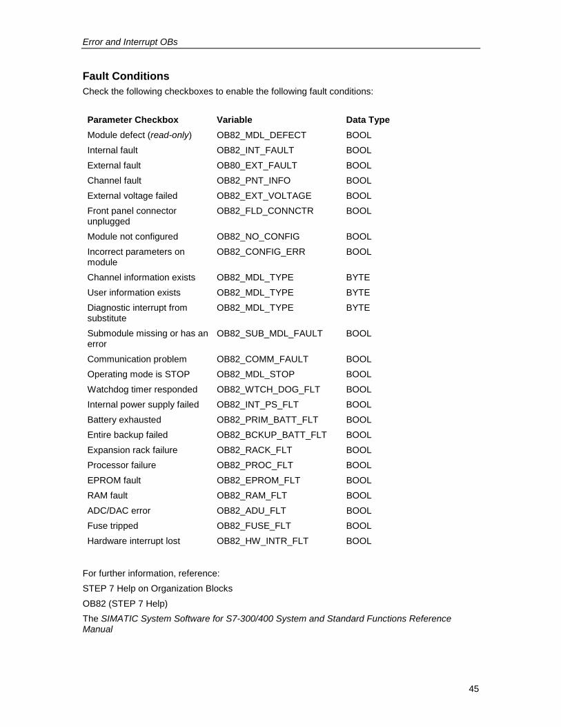
Error and Interrupt OBs
45
Fault ConditionsCheck the following checkboxes to enable the following fault conditions:
Parameter Checkbox Variable Data TypeModule defect (read-only) OB82_MDL_DEFECT BOOLInternal fault OB82_INT_FAULT BOOLExternal fault OB80_EXT_FAULT BOOLChannel fault OB82_PNT_INFO BOOLExternal voltage failed OB82_EXT_VOLTAGE BOOLFront panel connectorunplugged
OB82_FLD_CONNCTR BOOL
Module not configured OB82_NO_CONFIG BOOLIncorrect parameters onmodule
OB82_CONFIG_ERR BOOL
Channel information exists OB82_MDL_TYPE BYTEUser information exists OB82_MDL_TYPE BYTEDiagnostic interrupt fromsubstitute
OB82_MDL_TYPE BYTE
Submodule missing or has anerror
OB82_SUB_MDL_FAULT BOOL
Communication problem OB82_COMM_FAULT BOOLOperating mode is STOP OB82_MDL_STOP BOOLWatchdog timer responded OB82_WTCH_DOG_FLT BOOLInternal power supply failed OB82_INT_PS_FLT BOOLBattery exhausted OB82_PRIM_BATT_FLT BOOLEntire backup failed OB82_BCKUP_BATT_FLT BOOLExpansion rack failure OB82_RACK_FLT BOOLProcessor failure OB82_PROC_FLT BOOLEPROM fault OB82_EPROM_FLT BOOLRAM fault OB82_RAM_FLT BOOLADC/DAC error OB82_ADU_FLT BOOLFuse tripped OB82_FUSE_FLT BOOLHardware interrupt lost OB82_HW_INTR_FLT BOOL
For further information, reference:STEP 7 Help on Organization BlocksOB82 (STEP 7 Help)The SIMATIC System Software for S7-300/400 System and Standard Functions ReferenceManual
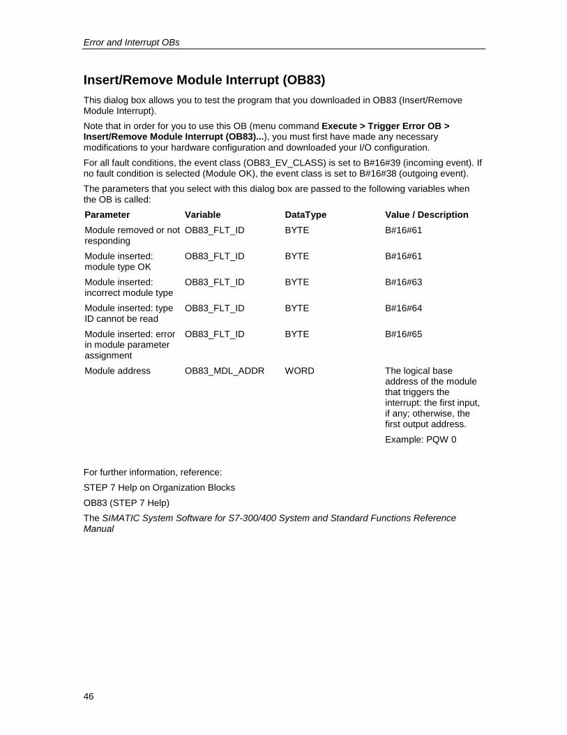
Error and Interrupt OBs
46
Insert/Remove Module Interrupt (OB83)This dialog box allows you to test the program that you downloaded in OB83 (Insert/RemoveModule Interrupt).Note that in order for you to use this OB (menu command Execute > Trigger Error OB >Insert/Remove Module Interrupt (OB83)...), you must first have made any necessarymodifications to your hardware configuration and downloaded your I/O configuration.For all fault conditions, the event class (OB83_EV_CLASS) is set to B#16#39 (incoming event). Ifno fault condition is selected (Module OK), the event class is set to B#16#38 (outgoing event).The parameters that you select with this dialog box are passed to the following variables whenthe OB is called:Parameter Variable DataType Value / DescriptionModule removed or notresponding
OB83_FLT_ID BYTE B#16#61
Module inserted:module type OK
OB83_FLT_ID BYTE B#16#61
Module inserted:incorrect module type
OB83_FLT_ID BYTE B#16#63
Module inserted: typeID cannot be read
OB83_FLT_ID BYTE B#16#64
Module inserted: errorin module parameterassignment
OB83_FLT_ID BYTE B#16#65
Module address OB83_MDL_ADDR WORD The logical baseaddress of the modulethat triggers theinterrupt: the first input,if any; otherwise, thefirst output address.Example: PQW 0
For further information, reference:STEP 7 Help on Organization BlocksOB83 (STEP 7 Help)The SIMATIC System Software for S7-300/400 System and Standard Functions ReferenceManual
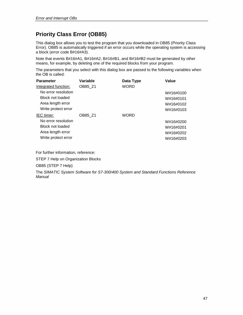
Error and Interrupt OBs
47
Priority Class Error (OB85)This dialog box allows you to test the program that you downloaded in OB85 (Priority ClassError). OB85 is automatically triggered if an error occurs while the operating system is accessinga block (error code B#16#A3).Note that events B#16#A1, B#16#A2, B#16#B1, and B#16#B2 must be generated by othermeans, for example, by deleting one of the required blocks from your program.The parameters that you select with this dialog box are passed to the following variables whenthe OB is called:Parameter Variable Data Type ValueIntegrated function:
No error resolutionBlock not loadedArea length errorWrite protect error
OB85_Z1 WORDW#16#0100W#16#0101W#16#0102W#16#0103
IEC timer:No error resolutionBlock not loadedArea length errorWrite protect error
OB85_Z1 WORDW#16#0200W#16#0201W#16#0202W#16#0203
For further information, reference:STEP 7 Help on Organization BlocksOB85 (STEP 7 Help)The SIMATIC System Software for S7-300/400 System and Standard Functions ReferenceManual
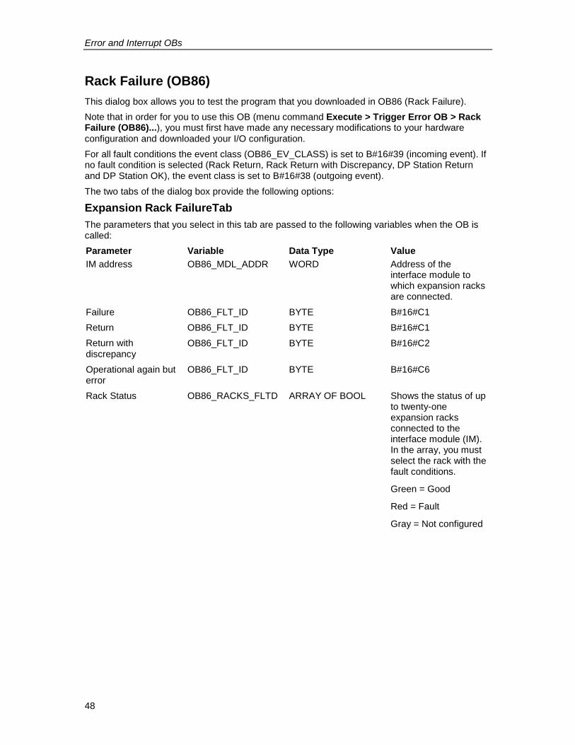
Error and Interrupt OBs
48
Rack Failure (OB86)This dialog box allows you to test the program that you downloaded in OB86 (Rack Failure).Note that in order for you to use this OB (menu command Execute > Trigger Error OB > RackFailure (OB86)...), you must first have made any necessary modifications to your hardwareconfiguration and downloaded your I/O configuration.For all fault conditions the event class (OB86_EV_CLASS) is set to B#16#39 (incoming event). Ifno fault condition is selected (Rack Return, Rack Return with Discrepancy, DP Station Returnand DP Station OK), the event class is set to B#16#38 (outgoing event).The two tabs of the dialog box provide the following options:
Expansion Rack FailureTabThe parameters that you select in this tab are passed to the following variables when the OB iscalled:Parameter Variable Data Type ValueIM address OB86_MDL_ADDR WORD Address of the
interface module towhich expansion racksare connected.
Failure OB86_FLT_ID BYTE B#16#C1Return OB86_FLT_ID BYTE B#16#C1Return withdiscrepancy
OB86_FLT_ID BYTE B#16#C2
Operational again buterror
OB86_FLT_ID BYTE B#16#C6
Rack Status OB86_RACKS_FLTD ARRAY OF BOOL Shows the status of upto twenty-oneexpansion racksconnected to theinterface module (IM).In the array, you mustselect the rack with thefault conditions.
Green = Good
Red = Fault
Gray = Not configured
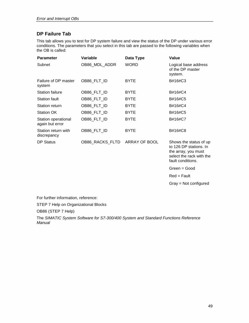
Error and Interrupt OBs
49
DP Failure TabThis tab allows you to test for DP system failure and view the status of the DP under various errorconditions. The parameters that you select in this tab are passed to the following variables whenthe OB is called:
Parameter Variable Data Type ValueSubnet OB86_MDL_ADDR WORD Logical base address
of the DP mastersystem.
Failure of DP mastersystem
OB86_FLT_ID BYTE B#16#C3
Station failure OB86_FLT_ID BYTE B#16#C4Station fault OB86_FLT_ID BYTE B#16#C5Station return OB86_FLT_ID BYTE B#16#C4Station OK OB86_FLT_ID BYTE B#16#C5Station operationalagain but error
OB86_FLT_ID BYTE B#16#C7
Station return withdiscrepancy
OB86_FLT_ID BYTE B#16#C8
DP Status OB86_RACKS_FLTD ARRAY OF BOOL Shows the status of upto 126 DP stations. Inthe array, you mustselect the rack with thefault conditions.
Green = Good
Red = Fault
Gray = Not configured
For further information, reference:STEP 7 Help on Organizational BlocksOB86 (STEP 7 Help)The SIMATIC System Software for S7-300/400 System and Standard Functions ReferenceManual

Error and Interrupt OBs
50
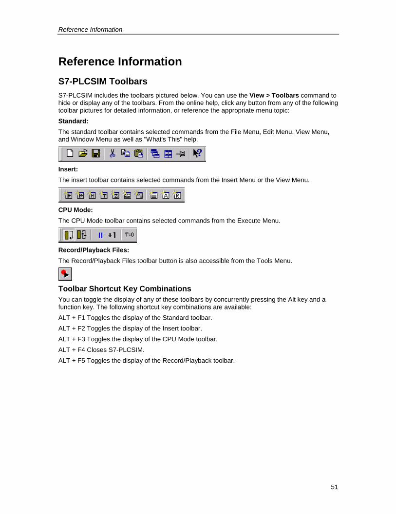
Reference Information
51
Reference InformationS7-PLCSIM ToolbarsS7-PLCSIM includes the toolbars pictured below. You can use the View > Toolbars command tohide or display any of the toolbars. From the online help, click any button from any of the followingtoolbar pictures for detailed information, or reference the appropriate menu topic:Standard:The standard toolbar contains selected commands from the File Menu, Edit Menu, View Menu,and Window Menu as well as "What's This" help.
Insert:The insert toolbar contains selected commands from the Insert Menu or the View Menu.
CPU Mode:The CPU Mode toolbar contains selected commands from the Execute Menu.
Record/Playback Files:The Record/Playback Files toolbar button is also accessible from the Tools Menu.
Toolbar Shortcut Key CombinationsYou can toggle the display of any of these toolbars by concurrently pressing the Alt key and afunction key. The following shortcut key combinations are available:ALT + F1 Toggles the display of the Standard toolbar.ALT + F2 Toggles the display of the Insert toolbar.ALT + F3 Toggles the display of the CPU Mode toolbar.ALT + F4 Closes S7-PLCSIM.ALT + F5 Toggles the display of the Record/Playback toolbar.
Reference Information
52
S7-PLCSIM MenusS7-PLCSIM includes the following menus for performing operations with the simulated PLC:
� File� Edit� View� Insert� PLC� Execute� Tools� Window� Help

Reference Information
53
File MenuThe S7-PLCSIM File menu contains the following commands:
New PLC Command
Click on or select the menu command File > New PLC to create a new simulated PLC.
Open PLC... Command
To find and open an existing (saved) simulation of a PLC, click or select the menu commandFile > Open PLC....
Close PLC CommandSelect the menu command File > Close PLC to close the currently open simulated PLC. Thiscommand closes the CPU view object and all other currently open view objects.Closing a simulated program can result in errors in applications which are currently connected tothe simulator.
Save PLC Command
Click or select the menu command File > Save PLC to save the current state of thesimulated PLC.
Save PLC As... CommandSelect the menu command File > Save PLC As... to save the current state of the simulated PLCas a new file.
Open Layout... CommandTo open a previously saved layout of S7-PLCSIM view objects, select the menu command File >Open Layout....
Reference Information
54
Close Layout CommandTo close the current layout of S7-PLCSIM view objects, select the menu command File > CloseLayout.
Save Layout CommandTo save the current layout of S7-PLCSIM view objects, select the menu command File > SaveLayout.
Save Layout As... CommandTo save the current layout of S7-PLCSIM view objects as a new file, select the menu commandFile > Save Layout As....
Recent Simulation CommandUse the menu command File > Recent Simulation to open a list of your four most recently usedprograms. Select file 1, 2, 3, or 4 from the list of recent simulations.
Recent Layout CommandUse the menu command File > Recent Layout to select from a list of your four most recentlyused layouts. Select file 1, 2, 3, or 4 from the list of recent layouts.
Exit CommandSelect the menu command File > Exit to close the simulated PLC and to exit the S7-PLCSIMapplication.Exiting S7-PLCSIM can result in errors in applications which are currently connected to thesimulator.

Reference Information
55
Edit MenuThe S7-PLCSIM Edit menu contains the following commands:
Undo CommandSelect the menu command Edit > Undo to reverse the last action you performed. Undo onlyapplies to editable text/numeric fields and to the commands of the Edit, Insert, and Windowmenus.The Undo command is also available from the right-click menu of any editable text field.
Cut Command
Select the Edit > Cut command or click to remove selected text and put it on the clipboard.
Copy Command
Select the Edit > Copy command or click to copy selected text and put it on the clipboard.
Paste Command
Select the Edit > Paste command or click to insert the contents of the clipboard (whateverwas last cut or copied) at the location of the cursor.
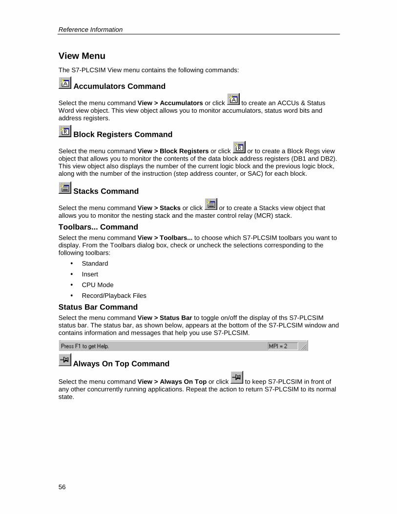
Reference Information
56
View MenuThe S7-PLCSIM View menu contains the following commands:
Accumulators Command
Select the menu command View > Accumulators or click to create an ACCUs & StatusWord view object. This view object allows you to monitor accumulators, status word bits andaddress registers.
Block Registers Command
Select the menu command View > Block Registers or click or to create a Block Regs viewobject that allows you to monitor the contents of the data block address registers (DB1 and DB2).This view object also displays the number of the current logic block and the previous logic block,along with the number of the instruction (step address counter, or SAC) for each block.
Stacks Command
Select the menu command View > Stacks or click or to create a Stacks view object thatallows you to monitor the nesting stack and the master control relay (MCR) stack.
Toolbars... CommandSelect the menu command View > Toolbars... to choose which S7-PLCSIM toolbars you want todisplay. From the Toolbars dialog box, check or uncheck the selections corresponding to thefollowing toolbars:
� Standard� Insert� CPU Mode� Record/Playback Files
Status Bar CommandSelect the menu command View > Status Bar to toggle on/off the display of ths S7-PLCSIMstatus bar. The status bar, as shown below, appears at the bottom of the S7-PLCSIM window andcontains information and messages that help you use S7-PLCSIM.
Always On Top Command
Select the menu command View > Always On Top or click to keep S7-PLCSIM in front ofany other concurrently running applications. Repeat the action to return S7-PLCSIM to its normalstate.
Reference Information
57
Insert MenuThe S7-PLCSIM Insert menu contains the following commands:
Input Variable Command
Click on or select the menu command Insert > Input Variable to create a view object thatallows you to monitor and modify variables in the process input (I) memory area. This view objectopens with a default memory location of IB0.
Output Variable Command
Click on or select the menu command Insert > Output Variable to create a view object thatallows you to monitor and modify variables in the process output (Q) memory area. This viewobject opens with a default memory location of QB0
Bit Memory Command
Click on or select the menu command Insert > Bit Memory to create a view object thatallows you to monitor and modify variables that are stored in the bit memory (M) area of the CPU.This view object opens with a default memory location of MB0.
Timer Command
Click on or select the menu command Insert > Timer to create a view object that allows youto monitor and modify the timers that are used by the program. This view object opens with adefault memory location of T 0.
Counter Command
Click on ( in German mnemonics) or select the menu command Insert > Counter tocreate a view object that allows you to monitor and modify the counters that are used by theprogram. This view object opens with a default memory location of C 0.
Generic Command
Click on or select the menu command Insert > Generic to create a view object that allowsyou to monitor and modify any of the variables used by the program, such as the input (I) oroutput (Q) memory areas. You can also access the data stored in the data blocks (DBs).
Vertical Bits Command
Click on or select the menu command Insert > Vertical Bits to create a view object displaysthe symbolic or absolute address next to each bit and allows you to monitor and modify any of thevariables used by the program, such as the input (I) or output (Q) memory areas. You can alsoaccess the data stored in the data blocks (DBs).
Reference Information
58
PLC MenuThe S7-PLCSIM PLC menu contains the following commands:
Power On CommandSelect the menu command PLC > Power On to simulate turning on the power to the PLC.
Power Off CommandSelect the menu command PLC > Power Off to simulate turning off the power to the PLC.
Clear/Reset CommandSelect the menu command PLC > Clear/Reset, or click on the "MRES" button on the CPU viewobject, to delete the blocks, reset the memory, and delete the hardware configuration of thesimulated PLC.When you perform a memory clear/reset, the CPU automatically goes to STOP mode.
MPI Address... CommandSelect the menu command PLC > MPI Address... to modify the network node address for thesimulated PLC. The new address is stored with the configuration of the simulated PLC when youuse the Save PLC or Save PLC As... menu commands.
Reference Information
59
Execute MenuThe S7-PLCSIM Execute menu contains the following commands:
Key Switch Position CommandSelect the menu command Execute > Key Switch Position and choose RUN-P, RUN, or STOPto put the simulated PLC in the desired operating mode. You can also change the mode byclicking the check-boxes in the CPU view object.
Startup Switch Position CommandSelect the menu command Execute > Startup Switch Position and pick a restart option todetermine what the simulated CPU will do when it is switched from STOP to RUN mode:
� Warm Start : the operating system calls OB100� Hot Start : the operating system calls OB101� Cold Start : the operating system calls OB102
Scan Mode CommandYou can choose from two modes of execution for your simulated program: Single Scan andContinuous Scan.
Single Scan Command
Select the menu command Execute > Scan Mode > Single Scan or click to set up the CPUfor executing the program one scan at a time. The CPU executes the complete program for onescan, then waits for you to request the next scan.
Continuous Scan Command
Select the menu command Execute > Scan Mode > Continuous Scan or click to set up theCPU for executing the program in a continuous cycle (in the same way that OB1 is executed bythe CPU). The CPU executes the program when the operating mode is set to RUN, and stopswhen the operating mode is set to STOP.
The scan starts by reading the peripheral inputs (PI) and updating the process-image input (I)memory. The CPU then executes the instructions of the program and updates the memory areas.The scan ends by writing the process-image output (Q) memory to the peripheral-output (PQ)memory.
Next Scan Command
Click on or select the menu command Execute > Next Scan to request that the simulatedCPU execute the next scan (if the simulation is set for Single Scan).
Pause Command
Click on or select the menu command Execute > Pause to momentarily halt the executionof the program in the simulated PLC without changing any of the data (such as the state of theoutputs). To resume the execution of the program, turn off the Pause function. The program thenstarts at the instruction where execution had been halted.If a STEP 7 application is connected to the simulated PLC, using Pause may cause theapplication to time out and disconnect. If this happens, turn off the Pause function and reconnectthe STEP 7 application.

Reference Information
60
Automatic Timers CommandThe timers in the simulated PLC can be set to either automatic or manual.
Select the menu command Execute > Automatic Timers to set up the CPU for executing thetimers automatically in the program.
Manual Timers CommandSelect the menu command Execute > Manual Timers to set up the CPU to allow you to enter aspecific value or to reset the timers in the program. To return to running the timers automatically,select the menu command Execute > Automatic Timers.
Reset Timers... CommandThe menu command Execute > Reset Timers... opens a dialog box allowing you to set the timevalue for each timer to its default value. You can reset all of the timers used by the program, oryou can reset timers individually.
To reset all of the timers in your program, use the Reset Timers toolbar button.
To reset an individual timer, use the Reset Timer button on the view object for that timer.
Trigger Error OB CommandThe menu command Execute > Trigger Error OB allows you to test how your program handlesdifferent interrupt OBs.
Scan Cycle Monitoring... CommandThe menu command Execute > Scan Cycle Monitoring... opens a dialog box allowing you toenable or disable scan cycle monitoring (watchdog timer) and set the maximum scan cyclemonitoring time (in milliseconds) for the simulation. The maximum scan cycle time is themaximum time the process is allowed to take for one full scan cycle of the S7 user program inOB1 and for the update of the relevant I/O. If this time is exceeded, the simulated PLC goes intoSTOP mode.
Reference Information
61
Tools MenuThe S7-PLCSIM Tools menu contains the following commands:
Record/Playback Command
Click on or select the menu command Tools > Record/Playback to record or play back asequence of events. The key sequence Alt + F5 toggles the display of the Record/Playbacktoolbar button.
Options CommandThe menu command Tools > Options contains the following options:
� Attach Symbols...
� Show Symbols
� Reference Data
� Symbol Table
Attach Symbols…Select the menu command Tools > Options > Attach Symbols... to use symbolic addressing inyour simulated program. This menu command invokes a dialog box where you can choose theSTEP 7 symbol table to be referenced.Once you have attached a symbol table, you can use the Show Symbols, Reference Data, andSymbol Data options.
Show SymbolsSelect the menu command Tools > Options > Show Symbols to display the symbolicaddresses used in your program. To hide the symbols, select the command again.This menu command is only available when a STEP 7 symbol table has been attached to thesimulated program using the Attach Symbols option.
Reference DataSelect the menu command Tools > Options > Reference Data to open the Displaying S7Reference Data application of STEP 7. You can use this application to debug your simulatedprogram.This menu command is only available when a STEP 7 symbol table has been attached to thesimulated program using the Attach Symbols option.
Symbol TableSelect the menu command Tools > Options > Symbol Table to open the STEP 7 Symbol Editorand view the currently attached symbol table.
This menu command is only available when a STEP 7 symbol table has been attached to thesimulated program using the Attach Symbols option.

Reference Information
62
Window MenuThe S7-PLCSIM Window menu contains the following commands:
Cascade CommandTo arrange windows so that they overlap (starting in the upper-left corner of the S7-PLCSIM
window), click or select the menu command Window > Cascade.
Tile Ordered CommandTo arrange the S7-PLCSIM view objects side by side, with the CPU view object in the top left,
click or select the menu command Window > Tile Ordered.
Arrange Icons CommandThe menu command Window > Arrange Icons arranges all minimized view objects (view objecticons) along the bottom edge of the S7-PLCSIM window.
1, 2, 3... 9 CommandYou can activate an open view object by selecting it from an alphabetical list in the Windowmenu. Select the number that corresponds to the desired view object. The currently active viewobject is indicated by a check mark.If you have more than 9 view objects open, you can select More Windows... to see a dialog boxwith a complete list.
Reference Information
63
Help MenuThe S7-PLCSIM Help menu contains the following commands:
Contents... CommandThe menu command Help > Contents... opens the Contents screen of the S7-PLCSIM Help.From the table of contents, you can expand any book and click any topic to view help on S7-PLCSIM.
Introduction CommandThe menu command Help > Introduction opens a Help topic that gives a general overview ofS7-PLCSIM and the tasks you can perform with it.
Getting Started CommandThe menu command Help > Getting Started opens a Help topic that helps you get started whenyou begin working with S7-PLCSIM for the first time.
Using Help CommandThe menu command Help > Using Help provides information on using the online Help system,useful if you are new to software products based on Microsoft Windows. Windows Help systemsare designed to serve as online manuals.
About... CommandThe menu command Help > About... gives you information on the version of the software and onthe copyright.
Help ButtonTo get information about S7-PLCSIM toolbars and features, follow these steps:
1. Click . The mouse pointer changes to a question-mark pointer .2. Click the part of the screen about which you want more information. S7-PLCSIM displays
the Help topic on that item.
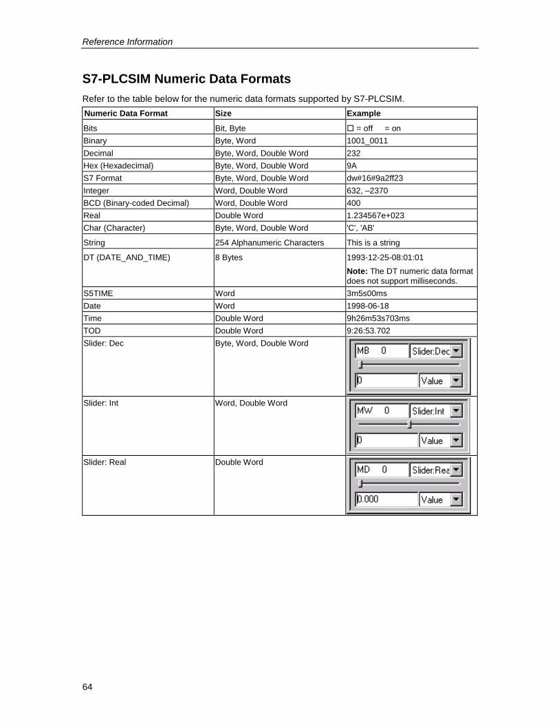
Reference Information
64
S7-PLCSIM Numeric Data FormatsRefer to the table below for the numeric data formats supported by S7-PLCSIM.Numeric Data Format Size Example
Bits Bit, Byte � = off = onBinary Byte, Word 1001_0011Decimal Byte, Word, Double Word 232Hex (Hexadecimal) Byte, Word, Double Word 9AS7 Format Byte, Word, Double Word dw#16#9a2ff23Integer Word, Double Word 632, –2370BCD (Binary-coded Decimal) Word, Double Word 400Real Double Word 1.234567e+023Char (Character) Byte, Word, Double Word 'C', 'AB'
String 254 Alphanumeric Characters This is a string
DT (DATE_AND_TIME) 8 Bytes 1993-12-25-08:01:01Note: The DT numeric data formatdoes not support milliseconds.
S5TIME Word 3m5s00msDate Word 1998-06-18Time Double Word 9h26m53s703msTOD Double Word 9:26:53.702Slider: Dec Byte, Word, Double Word
Slider: Int Word, Double Word
Slider: Real Double Word
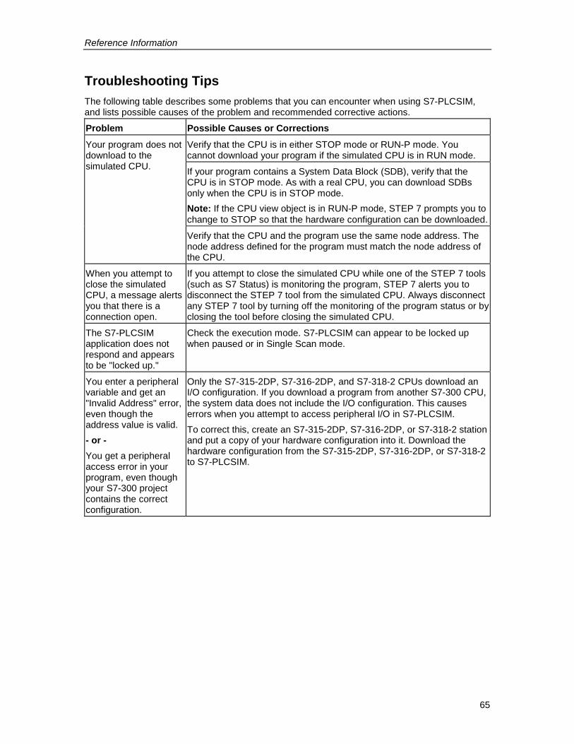
Reference Information
65
Troubleshooting TipsThe following table describes some problems that you can encounter when using S7-PLCSIM,and lists possible causes of the problem and recommended corrective actions.
Problem Possible Causes or CorrectionsVerify that the CPU is in either STOP mode or RUN-P mode. Youcannot download your program if the simulated CPU is in RUN mode.
If your program contains a System Data Block (SDB), verify that theCPU is in STOP mode. As with a real CPU, you can download SDBsonly when the CPU is in STOP mode.Note: If the CPU view object is in RUN-P mode, STEP 7 prompts you tochange to STOP so that the hardware configuration can be downloaded.
Your program does notdownload to thesimulated CPU.
Verify that the CPU and the program use the same node address. Thenode address defined for the program must match the node address ofthe CPU.
When you attempt toclose the simulatedCPU, a message alertsyou that there is aconnection open.
If you attempt to close the simulated CPU while one of the STEP 7 tools(such as S7 Status) is monitoring the program, STEP 7 alerts you todisconnect the STEP 7 tool from the simulated CPU. Always disconnectany STEP 7 tool by turning off the monitoring of the program status or byclosing the tool before closing the simulated CPU.
The S7-PLCSIMapplication does notrespond and appearsto be "locked up."
Check the execution mode. S7-PLCSIM can appear to be locked upwhen paused or in Single Scan mode.
You enter a peripheralvariable and get an"Invalid Address" error,even though theaddress value is valid.- or -You get a peripheralaccess error in yourprogram, even thoughyour S7-300 projectcontains the correctconfiguration.
Only the S7-315-2DP, S7-316-2DP, and S7-318-2 CPUs download anI/O configuration. If you download a program from another S7-300 CPU,the system data does not include the I/O configuration. This causeserrors when you attempt to access peripheral I/O in S7-PLCSIM.To correct this, create an S7-315-2DP, S7-316-2DP, or S7-318-2 stationand put a copy of your hardware configuration into it. Download thehardware configuration from the S7-315-2DP, S7-316-2DP, or S7-318-2to S7-PLCSIM.

Index
Index-1
IndexA
About, 63Accumulators, 6, 18, 32, 56ACCUs & status word view object, 32Activate view object, 62Address registers, 32Always on top command (view menu), 56Arrange icons command (window menu), 62Attach symbols... command (tools menu), 61Autoconfigured I/O, 21, 37Automatic timers command (execute menu),
59
BBack button, 12BCD (Binary-coded decimal), 64Binary, 64Binary-coded decimal (BCD), 64Bit memory, 10, 18, 35, 36Bit memory command (insert menu), 57Bit memory view object, 34Bits, 64Block registers, 18, 32, 56Block registers command (view menu), 56Block regs view object, 32Byte, 64
CC (counter), 10Cascade command (window menu), 62Changing CPU operating modes, 17Character (Char), 64Clear/Reset command (PLC menu), 23, 58Close layout command (file menu), 53Close PLC command (file menu), 30, 53Cold restart support, 3Communication redundancy error (OB73),
21, 37, 42Configuring an MPI address, 24Contents Tab, 12Contents... Command (Help Menu), 63Continuous Scan, 16, 20, 59Copy command (edit menu), 55Counter command (insert menu), 57Counters, 10, 18, 34, 35, 36, 57Counter view object, 34CPU accumulators, 32CPU indicators, 9, 10, 32CPU mode toolbar, 51CPU operating modes, 9, 32
changing, 17CPU redundancy error (OB72), 21, 37, 40
CPU view object, 4, 9, 32Cut command (edit menu), 55Cycling power for a simulated CPU, 17
DData blocks, 10, 35Data formats, 64Data types, 3Date, 64DATE_AND_TIME (DT), 64DC indicator, 10Debugging with S7-PLCSIM, 20Decimal, 64Diagnostic Interrupt (OB82), 21, 37, 44Differences from a real S7 PLC, 6Double word, 64Downloading problems, 65Downloading the modified configuration to
S7-PLCSIM, 23DP failure tab, 48DP indicator, 10DT (DATE_AND_TIME), 64
EEdit menu, 55Enable scan cycle monitoring, 28Ending the simulation session, 30Error OBs
OB70 (I/O redundancy error), 39OB72 (CPU redundancy error), 40OB73 (communication redundancy error),
42OB80 (rime error), 43OB85 (priority class error), 47OB86 (rack failure), 48
Event file playback, 25Execute menu, 59Exit command (file menu), 53Expansion rack failure tab, 48
FFault-tolerant H systems, 3Features of S7-PLCSIM, 1File menu, 53Formats
numeric data, 64
GGeneric command (insert menu), 57Generic variable, 18Generic view object, 35Getting Started, 4Getting started command (help menu), 63
Index
Index-2
HHardware configuration, 21, 22, 23, 37
downloading, 23modifying, 22
Hardware interrupt (OB40-OB47), 21, 37, 38Help button, 63Help buttons
Back, 12Hide, 12Print, 12Show, 12
Help menu, 63Help on help, 12Hexadecimal (Hex), 64Hide button, 12Hot start command (execute menu), 59
II (input), 10I/O (input/output), 6I/O redundancy error (OB70), 21, 37, 39Index tab, 12Input, 10Input variable command (insert menu), 57Input variable view object, 18, 33Input/output considerations, 21, 37Insert menu, 57Insert toolbar, 51Insert/remove module interrupt (OB83), 21,
37, 46Integer, 64Interrupt OBs, 6, 21, 22, 37
OB40-OB47 (hardware interrupt), 38OB82 (diagnostic interrupt), 44OB83 (insert/remove module interrupt), 46
Introduction, 1Introduction command (help menu), 63
KKey switch position, 9, 32Key switch position command (execute
menu), 59
LLayout
opening, 15saving, 28
Layout 1 2 3 4 command (file menu), 53LED, 10Locked-up S7-PLCSIM, 65
MM (bit memory), 10Main window, 8
Manual timers command (execute menu),59
Maximum slider value, 19MCR, 32Memory
peripheral, 6process, 6
Memory areas, 10, 33, 35Memory clear/reset, 9, 23, 58Menus, 8, 52
edit, 55execute, 59file, 53help, 63insert, 57PLC, 58tools, 61view, 56window, 62
Minimum slider value, 19Modifying bit memory, 34Modifying your hardware configuration, 21,
22, 37Monitor program simulation, 4Monitoring the scan cycle, 28Monitoring the simulated program, 18More windows, 62MPI address, 11, 24, 58MPI address... command (PLC menu), 58MRES, 23, 32, 58
NNesting stacks, 32New PLC command (file menu), 53Next scan command (execute menu), 59Numeric data formats, 64Numeric format
slider control, 19
OOB102, 3OB40 to OB47, 21, 37, 38OB70, 21, 37, 39OB72, 21, 37, 40OB73, 21, 37, 42OB80, 21, 37, 43OB82, 21, 37, 44OB83, 21, 37, 46OB85, 21, 37, 47OB86, 48OBs, 39, 48
communication redundancy error (OB73),42
CPU redundancy error (OB72), 40diagnostic interrupt (OB82), 44
Index
Index-3
OBs, continuedhardware interrupt (OB40-OB47), 38I/O redundancy error (OB70), 39insert/remove module interrupt (OB73), 46priority class error (OB85), 47rack failure (OB86), 48time error (OB80), 43using interrupts, 21, 37
Open connection message, 65Open layout... command (file menu), 53Open PLC... command (file menu), 53Opening a layout, 14, 15Opening a simulated PLC, 14Operating Modes, 6, 32
changing, 17CPU, 9
Options, 61Options button, 12Output, 10Output variable command (insert menu), 57Output variable view object, 18, 33
PPaste command (edit menu), 55Pause, 6, 9, 20, 59Pause command (execute menu), 59Peripheral access error, 65Peripheral variables, 6, 10, 35, 36
Input, 33Output, 33
PI (peripheral input), 10Playback, 25PLC
closing, 30saving, 29
PLC menu, 58Power cycle, 17Power off command (PLC menu), 58Power on command (PLC menu), 58PQ (peripheral output), 10Print button, 12Priority class error (OB85), 21, 37, 47Process image memory variables, 6
input, 33output, 33
Program simulation, 4
QQ (output), 10
RRack failure (OB86), 21, 37, 48Real data format, 64Real S7 PLC, 11
Differences from, 6
Recent layout command (file menu), 53Recent simulation command (file menu), 14,
53Record/playback, 3, 25Record/playback command (tools menu), 61Reference data command (tools menu), 61Reset timers... command (execute menu),
59Resetting the CPU memory, 23Resetting timers, 23, 34RUN, 9, 10RUN command (execute menu), 59RUN-P command (execute menu), 59
SS5TIME, 64S7 format, 64S7-300 CPUs, 21, 22, 37S7-400 CPUs, 21, 22, 37S7-PLCSIM
features, 1menus, 52modifying your hardware configuration, 22numeric data formats, 64toolbars, 51view objects, 31
Save layout as... command (file menu), 53Save layout command (file menu), 53Save PLC as... command (file menu), 53Save PLC command (file menu), 53Saving a layout, 28Saving a simulated PLC, 29Scan
continuous, 6, 16, 20cycle monitoring, 28single, 6, 16, 20
Scan cycle monitoring... command (executemenu), 59
Scan mode command (execute menu), 59Scan mode options
selecting, 16Search highlighting, 12Search tab, 12Selecting
maximum slider value, 19minimum slider value, 19Numeric Format, 19scan mode options, 16
SF indicator, 10Shortcut key combinations, 51Show button, 12Show symbols
symbolic addressing, 24, 61Show symbols command (tools menu), 61SIMATIC manager, 4Simulate modules, 11
Index
Index-4
Simulate Modules, 4, 8Simulated PLC
closing, 30opening, 14saving, 29
Simulated Programmonitoring, 18
Simulationending, 30starting, 11
Simulation on/off button, 11Single scan, 6, 16, 20Single scan command (execute menu), 59Slider control
using, 19Slider numeric format, 64Stacks, 18Stacks command (view menu), 56Stacks view object, 32Standard toolbar, 51Starting the simulation, 11Startup switch position command (execute
menu), 59Status bar command (view menu), 56Status word, 32STOP, 9, 10STOP command (execute menu), 59String, 64Symbol table command (tools menu), 61Symbol tooltips, 24, 31Symbolic addressing, 24
TT (timer), 10Tile ordered command (window menu), 62Time data format, 64Time error (OB80), 21, 37, 43Timers, 10, 18, 35, 36, 57, 59
resetting, 23Timer view object, 34Toolbars, 8, 51Toolbars... command (view menu), 56Tools menu, 61Tooltips, 24
Trigger error OB command (execute menu),59
Troubleshooting Tipsgeneral, 65record/playback, 25
Turning Simulation On, 11
UUndo command (edit menu), 55Using
help, 12, 63interrupt OBs in your program, 21, 37record/playback, 25S7-PLCSIM to debug your program, 20slider control, 19symbolic addressing, 24
VVariable view object (generic), 35Variable view object (vertical bits), 36Vertical bits command (insert menu), 57Vertical bits variable view object, 3, 24, 36View menu, 56View objects, 4, 8, 15, 18, 19, 24, 31
ACCUs & status word, 32bit memory, 34block regs, 32counters, 34CPU, 32generic variable, 35input variable, 33output variable, 33stacks, 32timers, 34vertical bits, 36
WWarm start command (execute menu), 59What's new in S7-PLCSIM
V 5.0, 3Window 1, 2, 3... 9 command (window
menu), 62Window Menu, 62Word, 64
Response FormYour comments and recommendations will help us to improve the quality and usefulness of ourpublications. Please take the first available opportunity to fill out this questionnaire and return it toSiemens.Please give each of the following questions your own personal mark within a range from 1 (verygood) to 5 (very poor).
Do the contents meet your requirements?
Is the information you need easy to find?
Is the text easy to understand?
Does the level of technical detail meet your requirements?
Please rate the quality of the graphics and tables.
Additional comments:_ _ _ _ _ _ _ _ _ _ _ _ _ _ _ _ _ _ _ _ _ _ _ _ _ _ _ _ _ _ _ _ _ __ _ _ _ _ _ _ _ _ _ _ _ _ _ _ _ _ _ _ _ _ _ _ _ _ _ _ _ _ _ _ _ _ __ _ _ _ _ _ _ _ _ _ _ _ _ _ _ _ _ _ _ _ _ _ _ _ _ _ _ _ _ _ _ _ _ __ _ _ _ _ _ _ _ _ _ _ _ _ _ _ _ _ _ _ _ _ _ _ _ _ _ _ _ _ _ _ _ _ __ _ _ _ _ _ _ _ _ _ _ _ _ _ _ _ _ _ _ _ _ _ _ _ _ _ _ _ _ _ _ _ _ __ _ _ _ _ _ _ _ _ _ _ _ _ _ _ _ _ _ _ _ _ _ _ _ _ _ _ _ _ _ _ _ _ __ _ _ _ _ _ _ _ _ _ _ _ _ _ _ _ _ _ _ _ _ _ _ _ _ _ _ _ _ _ _ _ _ __ _ _ _ _ _ _ _ _ _ _ _ _ _ _ _ _ _ _ _ _ _ _ _ _ _ _ _ _ _ _ _ _ __ _ _ _ _ _ _ _ _ _ _ _ _ _ _ _ _ _ _ _ _ _ _ _ _ _ _ _ _ _ _ _ _ __ _ _ _ _ _ _ _ _ _ _ _ _ _ _ _ _ _ _ _ _ _ _ _ _ _ _ _ _ _ _ _ _ __ _ _ _ _ _ _ _ _ _ _ _ _ _ _ _ _ _ _ _ _ _ _ _ _ _ _ _ _ _ _ _ _ __ _ _ _ _ _ _ _ _ _ _ _ _ _ _ _ _ _ _ _ _ _ _ _ _ _ _ _ _ _ _ _ _ __ _ _ _ _ _ _ _ _ _ _ _ _ _ _ _ _ _ _ _ _ _ _ _ _ _ _ _ _ _ _ _ _ __ _ _ _ _ _ _ _ _ _ _ _ _ _ _ _ _ _ _ _ _ _ _ _ _ _ _ _ _ _ _ _ _ __ _ _ _ _ _ _ _ _ _ _ _ _ _ _ _ _ _ _ _ _ _ _ _ _ _ _ _ _ _ _ _ _ __ _ _ _ _ _ _ _ _ _ _ _ _ _ _ _ _ _ _ _ _ _ _ _ _ _ _ _ _ _ _ _ _ __ _ _ _ _ _ _ _ _ _ _ _ _ _ _ _ _ _ _ _ _ _ _ _ _ _ _ _ _ _ _ _ _ _

Please check any industry that applies to you:
Automotive
Chemical
Electrical Machinery
Food
Instrument and Control
Non electrical Machinery
Petrochemical
Pharmaceutical
Plastic
Pulp and Paper
Textiles
Transportation
Other ___________________________
Mail your response to:SIEMENS ENERGY & AUTOMATION, INCATTN: TECHNICAL COMMUNICATIONS M/S 5193000 BILL GARLAND ROADPO BOX 1255JOHNSON CITY TN USA 37605-1255
Include this information:FromName: _ _ _ _ _ _ _ _ _ _ _ _ _ _ _ _ _ _ _ _ _ _ _ _ _ _ _ _ _ _ _Job Title: _ _ _ _ _ _ _ _ _ _ _ _ _ _ _ _ _ _ _ _ _ _ _ _ _ _ _ _ _ _ _Company Name _ _ _ _ _ _ _ _ _ _ _ _ _ _ _ _ _ _ _ _ _ _ _ _ _ _ _ _ _ _ _Street: _ _ _ _ _ _ _ _ _ _ _ _ _ _ _ _ _ _ _ _ _ _ _ _ _ _ _ _ _ _ _City and State: _ _ _ _ _ _ _ _ _ _ _ _ _ _ _ _ _ _ _ _ _ _ _ _ _ _ _ _ _ _ _Country: _ _ _ _ _ _ _ _ _ _ _ _ _ _ _ _ _ _ _ _ _ _ _ _ _ _ _ _ _ _ _
Telephone: _ _ _ _ _ _ _ _ _ _ _ _ _ _ _ _ _ _ _ _ _ _ _ _ _ _ _ _ _ _ _