Embed Size (px)
Citation preview

A-1S7-200 Programmable Controller System Manual C79000-G7076-C230-02
S7-200 Data Sheets
Chapter Overview
Section Description Page
A.1 General Technical Specifications A-3
A.2 CPU 212 DC Power Supply, DC Inputs, DC Outputs A-6
A.3 CPU 212 AC Power Supply, DC Inputs, Relay Outputs A-8
A.4 CPU 212 24 VAC Power Supply, 24 DC Inputs, Relay Outputs A-10
A.5 CPU 212 AC Power Supply, AC Inputs, AC Outputs A-12
A.6 CPU 212 AC Power Supply, Sourcing DC Inputs, Relay Outputs A-14
A.7 CPU 212 AC Power Supply, 24 VAC Inputs, AC Outputs A-16
A.8 CPU 212 AC Power Supply, AC Inputs, Relay Outputs A-18
A.9 CPU 214 DC Power Supply, DC Inputs, DC Outputs A-20
A.10 CPU 214 AC Power Supply, DC Inputs, Relay Outputs A-22
A.11 CPU 214 AC Power Supply, AC Inputs, AC Outputs A-24
A.12 CPU 214 AC Power Supply, Sourcing DC Inputs, Relay Outputs A-26
A.13 CPU 214 AC Power Supply, 24 VAC Inputs, AC Outputs A-28
A.14 CPU 214 AC Power Supply, AC Inputs, Relay Outputs A-30
A.15 CPU 215 DC Power Supply, DC Inputs, DC Outputs A-32
A.16 CPU 215 AC Power Supply, DC Inputs, Relay Outputs A-34
A.17 CPU 216 DC Power Supply, DC Inputs, DC Outputs A-36
A.18 CPU 216 AC Power Supply, DC Inputs, Relay Outputs A-38
A.19 EM221 Digital Input 8 x 24 VDC A-40
A.20 EM221 Digital Input 8 x 120 VAC A-41
A.21 EM221 Digital Sourcing Input 8 x 24 VDC A-42
A.22 EM221 Digital Input 8 x 24 VAC A-43
A.23 EM222 Digital Output 8 x 24 VDC A-44
A.24 EM222 Digital Output 8 x Relay A-45
A.25 EM222 Digital Output 8 x 120/230 VAC A-46
A.26 EM223 Digital Combination 4 x 24 VDC Input / 4 x 24 VDC Output A-48
A.27 EM223 Digital Combination 8 x 24 VDC Input / 8 x 24 VDC Output A-50
A.28 EM223 Digital Combination 16 x 24 VDC Input / 16 x 24 VDC Output A-52
A.29 EM223 Digital Combination 4 x 24 VDC Input / 4 x Relay Output A-54
A

A-2S7-200 Programmable Controller System Manual
C79000-G7076-C230-02
Section PageDescription
A.30 EM223 Digital Combination 4 x 120 VAC Input / 4 x 120 to 230 VAC Output A-55
A.31 EM223 Digital Combination 8 x 24 VDC Input / 8 x Relay Output A-56
A.32 EM223 Digital Combination 16 x 24 VDC Input / 16 x Relay Output A-58
A.33 EM231 Analog Input AI 3 x 12 Bits A-60
A.34 EM232 Analog Output AQ 2 x 12 Bits A-66
A.35 EM235 Analog Combination AI 3 / AQ 1 x 12 Bits A-69
A.36 Memory Cartridge 8K x 8 A-78
A.37 Memory Cartridge 16K x 8 A-79
A.38 Battery Cartridge A-80
A.39 I/O Expansion Cable A-81
A.40 PC/PPI Cable A-82
A.41 CPU 212 DC Input Simulator A-84
A.42 CPU 214 DC Input Simulator A-85
A.43 CPU 215/216 DC Input Simulator A-86
S7-200 Data Sheets

A-3S7-200 Programmable Controller System Manual C79000-G7076-C230-02
A.1 General Technical Specifications
National and International Standards
The national and international standards listed below were used to determine appropriateperformance specifications and testing for the S7-200 family of products. Table A-1 definesthe specific adherence to these standards.
Underwriters Laboratories, Inc.: UL 508 Listed (Industrial Control Equipment)
Canadian Standards Association: CSA C22.2 Number 142 Certified (Process ControlEquipment)
Factory Mutual Research: FM Class I, Division 2, Groups A, B, C, & D HazardousLocations, T4A
VDE 0160: Electronic equipment for use in electrical power installations
European Community (CE) Low Voltage Directive 73/23/EECEN 61131-2: Programmable controllers - Equipment requirements
European Community (CE) EMC Directive 89/336/EEC
Electromagnetic emission standards:EN 50081-1: residential, commercial, and light industryEN 50081-2: industrial environment
Electromagnetic immunity standards:EN 50082-2: industrial environment
S7-200 Data Sheets

A-4S7-200 Programmable Controller System Manual
C79000-G7076-C230-02
Technical Specifications
The S7-200 CPUs and all S7-200 expansion modules conform to the technical specificationslisted in Table A-1.
Table A-1 Technical Specifications for the S7-200 Family
Environmental Conditions — Transport and Storage
IEC 68-2-2, Test Bb, Dry heat andIEC 68-2-1, Test Ab, Cold
-40° C to +70° C
IEC 68-2-30, Test Db, Damp heat 25° C to 55° C, 95% humidity
IEC 68-2-31, Toppling 100 mm, 4 drops, unpacked
IEC 68-2-32, Free fall 1 m, 5 times, packed for shipment
Environmental Conditions — Operating
Functional range 0° C to 55° C, 95% maximum non-condensing humidity
IEC 68-2-14, Test Nb 5° C to 55° C, 3° C/minute
IEC 68-2-27 Mechanical shock 15 G, 11 ms pulse, 6 shocks in each of 3 axis
IEC 68-2-6 Sinusoidal vibration 0.35 mm peak-to-peak 10 to 57 Hz; 2 G panel mount, 1G DIN railmount, 57 Hz to 150 Hz; 10 sweeps each axis, 1 octave/minute
EN 60529, IP20 Mechanical protection Protects against finger contact with high voltage as tested by standardprobes. External protection is required for dust, dirt, water, and foreignobjects of less than 12.5 mm in diameter.
Electromagnetic Compatibility — Immunity 1 per EN50082-21
EN 61000-4-2 (IEC 801-2)Electrostatic discharge
8 kV air discharge to all surfaces and communication port
EN 50140 (IEC 801-3)Radiated electromagnetic fieldEN50204
26 MHz to 1 GHz 10 V/m, 80% modulation with 1 kHz signal
900 MHz ± 5 MHz, 10 V/m, 50% duty cycle, 200 Hz repetitionfrequency
EN 61000-4-4 (IEC 801-4)Fast transient bursts
2 kV, 5 kHz with coupling network to AC and DC system power2 kV, 5 kHz with coupling clamp to digital I/O and communications
EN 61000-4-5 (IEC 801-5)Surge immunity
2 kV asymmetrical, 1 kV symmetrical5 positive/5 negative pulses 0°, +90°, -90° phase angle(24 VDC circuits require external surge protection)
VDE 0160 Non-periodic overvoltage at 85 VAC line, 90° phase angle, apply 390 V peak, 1.3 ms pulseat 180 VAC line, 90° phase angle, apply 750 V peak, 1.3 ms pulse
S7-200 Data Sheets

A-5S7-200 Programmable Controller System Manual C79000-G7076-C230-02
Table A-1 Technical Specifications for the S7-200 Family, continued
Electromagnetic Compatibility — Conducted and Radiated Emissions2 per EN50081 -1 and -22
EN 55011, Class A, Group 1, conducted1
0.15 MHz to 0.5 MHz0.5 MHz to 5 MHz5 MHz to 30 MHz
< 79 dB (µV) Quasi-peak; < 66 dB (µV) Average< 73 dB (µV) Quasi-peak; < 60 dB (µV) Average< 73 dB (µV) Quasi-peak; < 60 dB (µV) Average
EN 55011, Class A, Group 1, radiated1
30 MHz to 230 kHz230 MHz to 1 GHz
30 dB (µV/m) Quasi-peak; measured at 30 m37 dB (µV/m) Quasi-peak; measured at 30 m
EN 55011, Class B, Group 1, conducted3
0.15 to 0.5 MHz
0.5 MHz to 5 MHz5 MHz to 30 MHz
< 66 dB (µV) Quasi-peak decreasing with log frequency to 56 dB (µV);< 56 dB (µV) Average decreasing with log frequency to 46 dB (µV)
< 56 dB (µV) Quasi-peak; < 46 dB (µV) Average< 60 dB (µV) Quasi-peak; < 50 dB (µV) Average
EN 55011, Class B, Group 1, radiated3
30 MHz to 230 kHz230 MHz to 1 GHz
30 dB (µV/m) Quasi-peak; measured at 10 m37 dB (µV/m) Quasi-peak; measured at 10 m
High Potential Isolation Test
24 V/5 V nominal circuits115/230 V circuits to ground115/230 V circuits to 115/230 V circuits230 V circuits to 24 V/5 V circuits115 V circuits to 24 V/5 V circuits
500 VAC (optical isolation boundaries)1,500 VAC1,500 VAC1,500 VAC1,500 VAC
1 Unit must be mounted on a grounded metallic frame with the S7-200 ground connection made directly to the mounting metal. Cablesare routed along metallic supports.
2 Applicable for all devices bearing the CE (European Community) mark.3 Unit must be mounted in a grounded metal enclosure. AC input power line must be equipped with a Schaffner FN 680-2.5/06 filter
or equivalent, 25. cm max. wire length from filters to the S7-200. The 24 VDC supply and sensor supply wiring must be shielded.
Relay Electrical Service Life
Figure A-1 shows typical performance data supplied by relay vendors. Actual performancemay vary depending upon your specific application.
0 1 2 3 4 5 6 7
100
300500
1000
4000
250 VAC resistive load30 VDC resistive load
250 VAC inductive load (p.f.=0.4)30 VDC inductive load (L/R=7msec)
Rated Operating Current (A)
Figure A-1 Electrical Service Life
S7-200 Data Sheets

A-6S7-200 Programmable Controller System Manual
C79000-G7076-C230-02
A.2 CPU 212 DC Power Supply, DC Inputs, DC Outputs
Order Number: 6ES7 212-1AA01-0XB0
General Features
Physical size (L x W x D) 160 x 80 x 62 mm (6.3 x 3.15 x 2.44 in.)
Weight 0.3 kg (0.7 lbs.)
Power dissipation 5 W at 1.75 A load
User program size/storage 512 words/EEPROM
User data size/storageData retention
512 words/RAM50 hr typical (8 hr minimum at 40° C)
Local I/O1 8 inputs/6 outputs
Maximum number ofexpansion modules
2
Digital I/O supported 64 inputs/64 outputs
Analog I/O supported 16 inputs/16 outputs
Boolean execution speed 1.2 µs/instruction
Internal memory bits 128
Timers 64 timers
Counters 64 counters
High-speed counters 1 software (2 KHz max.)
Analog adjustments 1
Standards compliance UL 508 CSA C22.2 142FM Class I, Division 2VDE 0160 compliantCE compliant
Output Points
Output type Sourcing transistor
Voltage range 20.4 VDC to 28.8 VDC
Maximum load currentPer single pointPer 2 adjacent pointsAll points total
0 to 40° C 55° C2
0.75 A 0.50 A1.00 A 0.75 A2.25 A 1.75 A
Inductive load clampingSingle pulse
Repetitive
(per common)2A L/R = 10 ms1A L/R = 100 ms1 W energy dissipation(1/2 Li2 x switch rate 1 W)
Leakage current 100 µA
Output Points (continued)
Switching delay 25 µs ON, 120 µs OFF
Surge current 4 A, 100 ms
Voltage drop 1.8 V maximum at maximumcurrent
Optical isolation 500 VAC, 1 min
Short circuit protection None
Input Points
Input type (IEC 1131-2) Type 1 sinking
ON state range 15-30 VDC, 4 mA minimum35 VDC, 500 ms surge
ON state nominal 24 VDC, 7 mA
OFF state maximum 5 VDC, 1 mA
Response time I0.0 to I0.7 0.3 ms maximum
Optical isolation 500 VAC, 1 min
Power Supply
Voltage range 20.4 to 28.8 VDC
Input current 60 mA typical, CPU only500 mA maximum load
UL/CSA rating 50 VA
Holdup time 10 ms minimum from 24 VDC
Inrush current 10 A peak at 28.8 VDC
Fusing (non-replaceable) 1 A, 125 V, slow blow
5 VDC current 260 mA for CPU340 mA for expansion I/O
Isolated No
DC Sensor Supply
Voltage range 16.4 to 28.8 VDC
Ripple/noise (<10MHz) Same as supplied voltage
24 VDC available currentShort-circuit current limit
180 mA< 600 mA
Isolated No
1 The CPU reserves 8 process-image input and 8 process-image output image register points for local I/O.2 Linear derate 40 to 55° C Vertical mount derate 10° C.
S7-200 Data Sheets

A-7S7-200 Programmable Controller System Manual C79000-G7076-C230-02
OUTPUTS M L+ 0.0 0.1 0.2 0.3 0.4 0.5 M L+ 24VDC
INPUTS1M 0.0 0.1 0.2 0.3 2M 0.4 0.5 M L+0.6
Inputs (15 VDC to 30 VDC)
24 VDC power for inputsensors or expansionmdules (180 mA)
+
Outputs (20.4 to 28.8 VDC)
+
0.7
++
3.3K Ω
470 Ω
DC 24V DCSENSORSUPPLY
Power supply
Note:1. Actual component values may vary.2. DC circuit grounds are optional.
DC 24V
36V
36V
Figure A-2 Connector Terminal Identification for CPU 212 DC/DC/DC
S7-200 Data Sheets

A-8S7-200 Programmable Controller System Manual
C79000-G7076-C230-02
A.3 CPU 212 AC Power Supply, DC Inputs, Relay Outputs
Order Number: 6ES7 212-1BA01-0XB0
General Features
Physical size (L x W x D) 160 x 80 x 62 mm (6.3 x 3.15 x 2.44 in.)
Weight 0.4 kg (0.9 lbs.)
Power dissipation 6 W
User program size/storage 512 words/EEPROM
User data size/storageData retention
512 words/RAM50 hr typical(8 hr minimum at 40° C)
Local I/O1 8 inputs/6 outputs
Maximum number ofexpansion modules
2
Digital I/O supported 64 inputs/64 outputs
Analog I/O supported 16 inputs/16 outputs
Boolean execution speed 1.2 µs/instruction
Internal memory bits 128
Timers 64 timers
Counters 64 counters
High-speed counters 1 software (2 KHz max.)
Analog adjustments 1
Standards compliance UL 508 CSA C22.2 142FM Class I, Division 2VDE 0160 compliantCE compliant
Output Points
Output type Relay, dry contact
Voltage range 5 to 30 VDC/250 VAC
Maximum load current 2 A/point, 6 A/common
Overcurrent surge 7 A with contacts closed
Isolation resistance 100 M minimum (new)
Switching delay 10 ms maximum
Lifetime 10,000,000 mechanical100,000 with rated load
Contact resistance 200 mmaximum (new)
Isolationcoil to contactcontact to contact(between open contacts)
1500 VAC, 1 min750 VAC, 1 min
Short circuit protection None
Input Points
Input type (IEC 1131-2) Type 1 sinking
ON state range 15-30 VDC, 4 mA minimum35 VDC, 500 ms surge
ON state nominal 24 VDC, 7 mA
OFF state maximum 5 VDC, 1 mA
Response timeI0.0 to I0.7 0.3 ms maximum
Optical isolation 500 VAC, 1 min
Power Supply
Voltage/frequency range 85 to 264 VAC at 47 to 63 Hz
Input current 4 VA typical, CPU only50 VA maximum load
Holdup time 20 ms minimum from 110 VAC
Inrush current 20 A peak at 264 VAC
Fusing (non-replaceable) 2 A, 250 V, slow blow
5 VDC current 260 mA for CPU340 mA for expansion I/O
Isolated Yes. Transformer, 1500 VAC,1 min
DC Sensor Supply
Voltage range 20.4 to 28.8 VDC
Ripple/noise (<10MHz) 1 V peak-to-peak maximum
24 VDC available currentShort circuit current limit
180 mA< 600 mA
Isolated No
1 The CPU reserves 8 process-image input and 8 process-image output image register points for local I/O.
S7-200 Data Sheets

A-9S7-200 Programmable Controller System Manual C79000-G7076-C230-02
OUTPUTS 1L 0.0 0.1 0.2 2L 0.3 0.4 0.5 N L1 85–264VAC
INPUTS1M 0.0 0.1 0.2 0.3 0.4 0.5 0.6 M L+0.7
Outputs (30 VDC/250 VAC) Power supply
Inputs (15 VDC to 30 VDC)
24 VDC power for input sensorsor expansion modules (180 mA)
2M
+ +
RELAY
DCSENSORSUPPLY
DC 24V
3.3 KΩ
470 Ω
N (-)
L (+)
Note:1. Actual component values may vary.2. Connect AC line to the L terminal.3. DC circuit grounds are optional.
N (-)
L (+)
Figure A-3 Connector Terminal Identification for CPU 212 AC/DC/Relay
S7-200 Data Sheets

A-10S7-200 Programmable Controller System Manual
C79000-G7076-C230-02
A.4 CPU 212 24 VAC Power Supply, DC Inputs, Relay Outputs
Order Number: 6ES7 212-1FA01-0XB0
General Features
Physical size (L x W x D) 160 x 80 x 62 mm (6.3 x 3.15 x 2.44 in.)
Weight 0.4 kg (0.9 lbs.)
Power dissipation 6 W
User program size/storage 512 words/EEPROM
User data size/storageData retention
512 words/RAM50 hr typical(8 hr minimum at 40° C)
Local I/O1 8 inputs/6 outputs
Maximum number ofexpansion modules
2
Digital I/O supported 64 inputs/64 outputs
Analog I/O supported 16 inputs/16 outputs
Boolean execution speed 1.2 µs/instruction
Internal memory bits 128
Timers 64 timers
Counters 64 counters
High-speed counters 1 software (2 KHz max.)
Analog adjustments 1
Standards compliance UL 508 CSA C22.2 142FM Class I, Division 2VDE 0160 compliantCE compliant
Output Points
Output type Relay, dry contact
Voltage range 5 to 30 VDC/250 VAC
Maximum load current 2 A /point, 6 A /common
Overcurrent surge 7 A with contacts closed
Isolation resistance 100 M minimum (new)
Switching delay 10 ms maximum
Lifetime 10,000,000 mechanical100,000 with rated load
Contact resistance 200 mmaximum (new)
Isolationcoil to contactcontact to contact(between open contacts)
1500 VAC, 1 min750 VAC, 1 min
Short circuit protection None
Input Points
Input type (IEC 1131-2) Type 1 sinking
ON state range 15-30 VDC, 4 mA minimum35 VDC, 500 ms surge
ON state nominal 24 VDC, 7 mA
OFF state maximum 5 VDC, 1 mA
Response timeI0.0 to I0.7 0.3 ms maximum
Optical isolation 500 VAC, 1 min
Power Supply
Voltage/frequency range 20 to 29 VAC at 47 to 63 Hz
Input current 4 VA typical, CPU only50 VA maximum load
Holdup time 20 ms minimum from 24 VAC
Inrush current 20 A peak at 29 VAC
Fusing (non-replaceable) 2 A, 250 V, slow blow
5 VDC current 260 mA for CPU340 mA for expansion I/O
Isolated Yes. Transformer, 500 VAC,1 min
DC Sensor Supply
Voltage range 20.4 to 28.8 VDC
Ripple/noise (<10MHz) 1 V peak-to-peak maximum
24 VDC available currentShort circuit current limit
180 mA< 600 mA
Isolated No
1 The CPU reserves 8 process-image input and 8 process-image output image register points for local I/O.
S7-200 Data Sheets

A-11S7-200 Programmable Controller System Manual C79000-G7076-C230-02
OUTPUTS 1L 0.0 0.1 0.2 2L 0.3 0.4 0.5 N L1 20–29VAC
INPUTS1M 0.0 0.1 0.2 0.3 0.4 0.5 0.6 M L+0.7
Outputs (30 VDC/250 VAC) Power supply
Inputs (15 VDC to 30 VDC)
24 VDC power for input sensorsor expansion modules (180 mA)
2M
+ +
RELAY
DCSENSORSUPPLY
DC 24V
3.3 KΩ
470 Ω
N (-)
L (+)
Note:1. Actual component values may vary.2. Connect AC line to the L terminal.3. DC circuit grounds are optional.
N (-)
L (+)
Figure A-4 Connector Terminal Identification for CPU 212 24 VAC/DC/Relay
S7-200 Data Sheets

A-12S7-200 Programmable Controller System Manual
C79000-G7076-C230-02
A.5 CPU 212 AC Power Supply, AC Inputs, AC Outputs
Order Number: 6ES7 212-1CA01-0XB0
General Features
Physical size (L x W x D) 160 x 80 x 62 mm (6.3 x 3.15 x 2.44 in.)
Weight 0.4 kg (0.9 lbs.)
Power dissipation 7 W at 2.5 A load
User program size/storage 512 words/EEPROM
User data size/storageData retention
512 words/RAM50 hr typical(8 hr minimum at 40° C)
Local I/O1 8 inputs/6 outputs
Maximum number ofexpansion modules
2
Digital I/O supported 64 inputs/64 outputs
Analog I/O supported 16 inputs/16 outputs
Boolean execution speed 1.2 µs/instruction
Internal memory bits 128
Timers 64 timers
Counters 64 counters
High-speed counters 1 software (50 Hz max.)
Analog adjustments 1
Standards compliance UL 508 CSA C22.2 142FM Class I, Division 2CE compliant
Output Points
Output type Triac, zero-crossing
Voltage/frequency range 20 to 264 VAC, 47 to 63 Hz
Load circuit power factor 0.3 to 1.0
Inductive load clamping MOV 275 V working voltage
Maximum load currentper single pointper 2 adjacent pointsall points total*
0 to 40° C 55° C2
1.20 A 1.00 A1.50 A 1.25 A3.50 A 2.50 A
Minimum load current 30 mA
Leakage current 1.5 mA, 120 VAC/2.0 mA,240 VAC
Output Points (continued)
Switching delay 1/2 cycle
Surge current 30 A peak, 1 cycle / 10 A peak, 5 cycle
Voltage drop 1.5 V maximum at maximumcurrent
Optical isolation 1500 VAC, 1 min
Short circuit protection None
Input Points
Input type (IEC 1131-2) Type 1 sinking
ON state range 79 to 135 VAC, 47 to 63 Hz, 4 mA minimum
ON state nominal 120 VAC, 60 Hz, 7 mA
OFF state maximum 20 VAC, 1 mA
Response time 10 ms typical, 15 ms max.
Optical isolation 1500 VAC, 1 min
Power Supply
Voltage/frequency range 85 to 264 VAC at 47 to 63 Hz
Input current 4 VA typical, CPU only50 VA maximum load
Holdup time 20 ms minimum from 110 VAC
Inrush current 20 A peak at 264 VAC
Fusing (non-replaceable) 2 A, 250 V, slow blow
5 VDC current 320 mA for CPU280 mA for expansion I/O
Isolated Yes. Transformer, 1500 VAC,1 min
DC Sensor Supply
Voltage range 20.4 to 28.8 VDC
Ripple/noise (<10MHz) 1 V peak-to-peak maximum
24 VDC available current 180 mA
Short circuit current limit < 600 mA
Isolated No
1 The CPU reserves 8 process-image input and 8 process-image output register points for local I/O.2 Linear derate 40 to 55° C. Vertical mount derate 10° C.
S7-200 Data Sheets

A-13S7-200 Programmable Controller System Manual C79000-G7076-C230-02
1L 0.0 0.1 0.2 2L 0.3 0.4 0.5 N L1 85–264VAC
N 0.0 0.1 0.2 0.3 0.4 0.5 0.6 M L+0.7
Outputs (20 VAC to 264 VAC) Power supply
Inputs (79 VAC to 135 VAC)
24 VDC power for input sensorsor expansion modules (180 mA)
10 Ω0.0068 µF
275V MOV
0.15 µF 470 KΩ
390 Ω
ACOUTPUTS
DCSENSORSUPPLY
AC 120V INPUTS
3.3 KΩNote: Actual component values may vary.
Figure A-5 Connector Terminal Identification for CPU 212 AC/AC/AC
S7-200 Data Sheets

A-14S7-200 Programmable Controller System Manual
C79000-G7076-C230-02
A.6 CPU 212 AC Power Supply, Sourcing DC Inputs, Relay Outputs
Order Number: 6ES7 212-1BA10-0XB0
General Features
Physical size (L x W x D) 160 x 80 x 62 mm (6.3 x 3.15 x 2.44 in.)
Weight 0.4 kg (0.9 lbs.)
Power dissipation 6 W
User program size/storage 512 words/EEPROM
User data size/storageData retention
512 words/RAM50 hr typical(8 hr minimum at 40° C)
Local I/O1 8 inputs/6 outputs
Maximum number ofexpansion modules
2
Digital I/O supported 64 inputs/64 outputs
Analog I/O supported 16 inputs/16 outputs
Boolean execution speed 1.2 µs/instruction
Internal memory bits 128
Timers 64 timers
Counters 64 counters
High-speed counters 1 software (2 KHz max.)
Analog adjustments 1
Standards compliance UL 508 CSA C22.2 142FM Class I, Division 2VDE 0160 compliantCE compliant
Output Points
Output type Relay, dry contact
Voltage range 5 to 30 VDC/250 VAC
Maximum load current 2 A /point, 6 A/common
Overcurrent surge 7 A with contacts closed
Isolation resistance 100 M minimum (new)
Switching delay 10 ms maximum
Lifetime 10,000,000 mechanical100,000 with rated load
Contact resistance 200 mmaximum (new)
Isolationcoil to contactcontact to contact(between open contacts)
1500 VAC, 1 min750 VAC, 1 min
Short circuit protection None
Input Points
Type Sourcing
Input voltage range 15 to 30 VDC, 35 VDC for 500 ms
ON state 4 mA minimum
OFF state 1 mA maximum
Response timeI0.0 to I0.7 0.3 ms maximum
Optical isolation 500 VAC, 1 min
Power Supply
Voltage/frequency range 85 to 264 VAC at 47 to 63 Hz
Input current 4 VA typical, CPU only50 VA maximum load
Holdup time 20 ms minimum from 110 VAC
Inrush current 20 A peak at 264 VAC
Fusing (non-replaceable) 2 A, 250 V, slow blow
5 VDC available current 260 mA for CPU340 mA for expansion I/O
Isolated Yes. Transformer, 1500 VAC,1 min
DC Sensor Supply
Voltage range 20.4 to 28.8 VDC
Ripple/noise (<10MHz) 1 V peak-to-peak maximum
24 VDC available currentshort circuit current limit
180 mA< 600 mA
Isolated No
1 The CPU reserves 8 process-image input and 8 process-image output register points for local I/O.
S7-200 Data Sheets

A-15S7-200 Programmable Controller System Manual C79000-G7076-C230-02
1L 0.0 0.1 0.2 2L 0.3 0.4 0.5 N L1 85–264VAC
1L 0.0 0.1 0.2 0.3 0.4 0.5 0.6 M L+0.7
Outputs (30 VDC/250 VAC) Power supply
Inputs (15 VDC to 30 VDC)
24 VDC power for input sensorsor expansion modules (180 mA)
2L
+
RELAYOUTPUTS
DCSENSORSUPPLY
DC 24VINPUTS
3.3 KΩ470 Ω
N (-)
L (+)
Note: 1. Actual component values may vary.2. Connect AC line to the L terminal.3. Input circuit ground is optional.
N (-)
L (+)
+Figure A-6 Connector Terminal Identification for CPU 212 AC/Sourcing DC/Relay
S7-200 Data Sheets

A-16S7-200 Programmable Controller System Manual
C79000-G7076-C230-02
A.7 CPU 212 AC Power Supply, 24 VAC Inputs, AC Outputs
Order Number: 6ES7 212-1DA01-0XB0
General Features
Physical size (L x W x D) 160 x 80 x 62 mm (6.3 x 3.15 x 2.44 in.)
Weight 0.4 kg (0.9 lbs.)
Power dissipation 7 W at 2.5 A load
User program size/storage 512 words/EEPROM
User sata size/storageData retention
512 words/RAM50 hr typical(8 hr minimum at 40° C)
Local I/O1 8 inputs/6 outputs
Maximum number ofexpansion modules
2
Digital I/O supported 64 inputs/64 outputs
Analog I/O supported 16 inputs/16 outputs
Boolean execution speed 1.2 µs/instruction
Internal memory bits 128
Timers 64 timers
Counters 64 counters
High-speed counters 1 software (50 Hz max.)
Analog adjustments 1
Standards compliance UL 508 CSA C22.2 142FM Class I, Division 2CE compliant
Output Points
Output type Triac, zero-crossing
Voltage/frequency range 20 to 264 VAC, 47 to 63 Hz
Load circuit power factor 0.3 to 1.0
Inductive load clamping MOV 275 V working voltage
Maximum load currentper single pointper 2 adjacent pointsall points total
0 to 40° C 55° C 2
1.20 A 1.00 A1.50 A 1.25 A3.50 A 2.50 A
Minimum load current 30 mA
Leakage current 1.5 mA, 120 VAC/2.0 mA,240 VAC
Output Points (continued)
Switching delay 1/2 cycle
Surge current 30 A peak, 1 cycle / 10 A peak, 5 cycle
Voltage drop 1.5 V maximum at maximumcurrent
Optical isolation 1500 VAC, 1 min
Short circuit protection None
Input Points
Input type (IEC 1131-2) Type 1 sinking
ON state range 15 to 30 VAC, 47 to 63 Hz, 4 mA minimum
ON state nominal 24 VAC, 60 Hz, 7 mA
OFF state maximum 5 VAC, 1 mA
Response time 10 ms typical, 15 ms max.
Optical isolation 1500 VAC, 1 min
Power Supply
Voltage/frequency range 85 to 264 VAC at 47 to 63 Hz
Input current 4 VA typical, CPU only50 VA maximum load
Holdup time 20 ms minimum from 110 VAC
Inrush current 20 A peak at 264 VAC
Fusing (non-replaceable) 2 A, 250 V, slow blow
5 VDC current 320 mA for CPU280 mA for expansion I/O
Isolated Yes. Transformer, 1500 VAC,1 min
DC Sensor Supply
Voltage range 20.4 to 28.8 VDC
Ripple/noise (<10MHz) 1 V peak-to-peak maximum
24 VDC available current 180 mA
Short circuit current limit < 600 mA
Isolated No
1 The CPU reserves 8 process-image input and 8 process-image output register points for local I/O.2 Linear derate 40 to 55° C. Vertical mount derate 10° C
S7-200 Data Sheets

A-17S7-200 Programmable Controller System Manual C79000-G7076-C230-02
1L 0.0 0.1 0.2 2L 0.3 0.4 0.5 N L1 85–264VAC
N 0.0 0.1 0.2 0.3 0.4 0.5 0.6 M L+0.7
Outputs (20 VAC to 264 VAC) Power supply
Inputs (15 VAC to 30 VAC)
24 VDC power for input sensorsor expansion modules (180 mA)
10 Ω0.0068 µF
275V MOV
390 Ω
ACOUTPUTS
DCSENSORSUPPLY
AC 24VINPUTS
3.3 KΩ
Note: Actual component values may vary.
Figure A-7 Connector Terminal Identification for CPU 212 AC/AC/AC
S7-200 Data Sheets

A-18S7-200 Programmable Controller System Manual
C79000-G7076-C230-02
A.8 CPU 212 AC Power Supply, AC Inputs, Relay Outputs
Order Number: 6ES7 212-1GA01-0XB0
General Features
Physical Size (L x W x D) 160 x 80 x 62 mm (6.3 x 3.15 x 2.44 in.)
Weight 0.4 kg (0.9 lbs.)
Power Dissipation 6 W
User program size/storage 512 Words / EEPROM
User data size/storageData retention
512 Words / RAM50 hr typical(8 hr minimum at 40° C)
Local I/O1 8 Inputs / 6 Outputs
Maximum Number ofExpansion Modules
2
Digital I/O Supported 64 Inputs / 64 Outputs
Analog I/O Supported 16 Inputs / 16 Outputs
Boolean Execution Speed 1.2 µs/instruction
Internal Memory Bits 128
Timers 64 Timers
Counters 64 Counters
High-speed counters 1 Software (2 KHz max.)
Analog Adjustments 1
Standards Compliance UL 508 CSA C22.2 142FM Class I, Division 2VDE 0160 compliantCE compliant
Output Points
Output Type Relay, dry contact
Voltage Range 5 to 30 VDC / 250 VAC
Maximum Load Current 2 A/point
Overcurrent Surge 7 A with contacts closed
Isolation Resistance 100 M minimum (new)
Switching Delay 10 ms maximum
Lifetime 10,000,000 Mechanical100,000 with Rated Load
Contact Resistance 200 mmaximum (new)
IsolationCoil to ContactContact to Contact
1500 VAC, 1 minute1000 VAC, 1 minute
Short Circuit Protection None
Input Points
Input Type (IEC 1131-2) Type 1 Sinking
ON State Range 79 to 135 VAC, 47 to 63 Hz.4 mA minimum
ON State Nominal 120 VAC, 60 Hz, 7mA
OFF State Maximum 20 VAC, 1 mA
Response Time 10 ms typical, 15 ms max.
Optical Isolation 1500 VAC, 1 minute
Power Supply
Voltage/frequency Range 85 to 264 VAC at 47 to 63 Hz
Input Current 4 VA typical, CPU only50 VA maximum load
Hold Up Time 20 ms minimum from 110 VAC
Inrush Current 20 A peak at 264 VAC
Fusing (non-replaceable) 2 A, 250 V, Slow Blow
5 VDC Current 260 mA for CPU340 mA for expansion I/O
Isolated Yes. Transformer, 1500 VAC,1 minute
DC Sensor Supply
Voltage Range 20.4 to 28.8 VDC
Ripple/noise (<10Mhz) 1 V peak-to-peak maximum
24 VDC Available CurrentShort Circuit Current Limit
180 mA< 600 mA
Isolated No
1 The CPU reserves 8 input and 8 output image register points for local I/O.
S7-200 Data Sheets

A-19S7-200 Programmable Controller System Manual C79000-G7076-C230-02
OUTPUTS 1L 0.0 0.1 0.2 2L 0.3 0.4 0.5 N L1 85–264VAC
Outputs (30 VDC / 250 VAC) Power Supply
RELAY
N (-)
L (+)
Note:1. Actual component values may vary.2. Connect AC line to the L terminal.
N (-)
L (+)
N 0.0 0.1 0.2 0.3 0.4 0.5 0.6 M L+0.7
Inputs (79 to 135 VAC)
24 VDC Power for Input Sensorsor Expansion Modules (180 mA)
0.0068 µF
0.15 µF 470K ohms
390 ohms
DCSENSORSUPPLY
AC 120V INPUTS
3.3K ohms
Figure A-8 Connector Terminal Identification for CPU 212 AC/AC/Relay
S7-200 Data Sheets

A-20S7-200 Programmable Controller System Manual
C79000-G7076-C230-02
A.9 CPU 214 DC Power Supply, DC Inputs, DC Outputs
Order Number: 6ES7 214-1AC01-0XB0
General Features
Physical size (L x W x D) 197 x 80 x 62 mm (7.76 x 3.15 x 2.44 in.)
Weight 0.4 kg (0.9 lbs.)
Power dissipation 8 W at 3 A load
User program size/storage 2 Kwords/EEPROM
User data size/storage 2 Kwords/RAM
Data and TOD retention Supercap
Optional battery
190 hr typ. (120 hr minimum at 40° C)200 days continuous usage
Local I/O1 14 inputs/10 outputs
Max. I/O expansion modules 7
Digital I/O supported 64 inputs/64 outputs
Analog I/O supported 16 inputs/16 outputs
Boolean execution speed 0.8 µs/instruction
Internal memory bits 256
Timers 128 timers
Counters 128 counters
High-speed counters 1 software (2 KHz max.)2 hardware (7 KHz max. ea.)
TOD clock tolerance 6 minutes per month
Pulse outputs 2 (4 KHz max. each)
Analog adjustments 2
Standards compliance UL 508 CSA C22.2 142FM Class I, Division 2VDE 0160 compliantCE compliant
Input Points
Input type (IEC 1131-2) Type 1 sinking
ON state range 15-30 VDC, 4 mA minimum35 VDC, 500 ms surge
ON state nominal 24 VDC, 7 mA
OFF state maximum 5 VDC, 1 mA
Maximum response time I0.0 to I1.5
I0.6 to I1.5 as used by HSC1 and HSC2
0.2 ms to 8.7 ms selectable0.2 ms default30 µs typical / 70 µs max.
Optical isolation 500 VAC, 1 min
Output Points
Output type Sourcing Transistor
Voltage range 20.4 to 28.8 VDC
Maximum load currentper single pointper 2 adjacent pointsall points total
0 to 40° C 55° C2
0.75 A 0.50 A1.00 A 0.75 A4.00 A 3.00 A
Inductive load clampingSingle pulse
Repetitive
(per common)2A L/R = 10 ms1A L/R = 100 ms1 W energy dissipation(1/2 Li2 x switch rate 1 W)
Leakage current 100 µA
Switching delay 25 µs ON, 120 µs OFF
Surge current 4 A, 100 ms
Voltage drop 1.8 V maximum at maximumcurrent
Optical isolationShort circuit protection
500 VAC, 1 minNone
Power Supply
Voltage range 20.4 to 28.8 VDC
Input current 85 mA typical, CPU only900 mA, maximum load
UL/CSA rating 50VA
Holdup time 10 ms min. from 24 VDC
Inrush current 10 A peak at 28.8 VDC
Fusing (non-replaceable) 1 A, 125 V, slow blow
5 VDC current 340 mA for CPU660 mA for expansion I/O
Isolated No
DC Sensor Supply
Voltage range 16.4 to 28.8 VDC
Ripple/noise (<10MHz) Same as supplied voltage
24 VDC available current 280 mA
Short circuit current limit < 600 mA
Isolated No
1 The CPU reserves 16 process-image input and 16 process-image output register points for local I/O.2 Linear derate 40 to 55° C. Vertical mount derate 10° C
S7-200 Data Sheets

A-21S7-200 Programmable Controller System Manual C79000-G7076-C230-02
1M 0.0 0.1 0.2 0.3 0.4 0.5 0.6 M L+0.7 DCSENSORSUPPLY
DC 24VINPUTS
2M 1.0 1.1 1.2 1.3 1.4 1.5
++
++
Inputs (15 VDC to 30 VDC)
24 VDC power for inputsensors or expansionmodules (280 mA)
+
Outputs (20.4 VDC to 28.8 VDC)
3.3 KΩ
470 Ω
Power supply
1M 1L+ 0.0 0.1 0.2 0.3 0.4 2M M L+ 24VDCDC 24V
OUTPUTS 2L+ 0.5 0.6 0.7 1.0 1.1
Note: 1. Actual component values may vary.2. DC circuit grounds are optional.36V
36V
Figure A-9 Connector Terminal Identification for CPU 214 DC/DC/DC
S7-200 Data Sheets

A-22S7-200 Programmable Controller System Manual
C79000-G7076-C230-02
A.10 CPU 214 AC Power Supply, DC Inputs, Relay Outputs
Order Number: 6ES7 214-1BC01-0XB0
General Features
Physical size (L x W x D) 197 x 80 x 62 mm (7.76 x 3.15 x 2.44 in.)
Weight 0.5 kg (1.0 lbs.)
Power dissipation 9 W
User program size/Storage 2 Kwords/EEPROM
User data size/storage 2 Kwords/RAM
Data and TOD retention Supercap
Optional battery
190 hr typ. (120 hr minimum at 40° C)200 days continuous usage
Local I/O1 14 inputs/10 outputs
Max. I/O expansion modules 7
Digital I/O supported 64 inputs/64 outputs
Analog I/O supported 16 inputs/16 outputs
Boolean execution speed 0.8 µs/instruction
Internal memory bits 256
Timers 128 timers
Counters 128 counters
High-speed counters 1 software (2 KHz max.)2 hardware (7 KHz max. ea.)
TOD clock tolerance 6 minutes per month
Pulse outputs Not recommended
Analog adjustments 2
Standards compliance UL 508 CSA C22.2 142FM Class I, Division 2VDE 0160 compliantCE compliant
Input Points
Input type (IEC 1131-2) Type 1 sinking
ON state range 15-30 VDC, 4 mA minimum35 VDC, 500 ms surge
ON state nominal 24 VDC, 7 mA
OFF state maximum 5 VDC, 1 mA
Maximum response timeI0.0 to I1.5
I0.6 to I1.5 as used by HSC1 and HSC2
0.2 ms to 8.7 ms selectable0.2 ms default30 µs typical / 70 µs max.
Optical isolation 500 VAC, 1 min
Output Points
Output type Relay, dry contact
Voltage range 5 to 30 VDC/250 VAC
Maximum load current 2 A/point, 8 A/common
Overcurrent surge 7 A with contacts closed
Isolation resistance 100 M minimum (new)
Switching delay 10 ms maximum
Lifetime 10,000,000 mechanical100,000 with rated load
Contact resistance 200 m maximum (new)
Isolationcoil to contactcontact to contact(between open contacts)
1500 VAC, 1 min750 VAC, 1 min
Short circuit protection none
Power Supply
Voltage/frequency range 85 to 264 VAC at 47 to 63 Hz
Input current 4.5 VA typical, CPU only50 VA max. load
Holdup time 20 ms min. from 110 VAC
Inrush current 20 A peak at 264 VAC
Fusing (non-replaceable) 2 A, 250 V, slow blow
5 VDC current 340 mA for CPU660 mA for expansion I/O
Isolated Yes. Transformer, 1500 VAC,1 min
DC Sensor Supply
Voltage range 20.4 to 28.8 VDC
Ripple/noise (<10MHz) 1 V peak-to-peak maximum
24 VDC available current 280 mA
Short circuit current limit < 600 mA
Isolated No
1 The CPU reserves 16 process-image input and 16 process-image output register points for local I/O.
S7-200 Data Sheets

A-23S7-200 Programmable Controller System Manual C79000-G7076-C230-02
Outputs (30 VDC/250 VAC)
Inputs (15 VDC to 30 VDC)
24 VDC power for inputsensors or expansionmodules (280 mA)+ +
3.3 KΩ
470 Ω
Power supply
1L 0.0 0.1 0.2 0.3 2L 0.4 N L1 85–264VACRELAY
OUTPUTS 0.5 0.6 3L 0.7 1.0
1M 0.0 0.1 0.2 0.3 0.4 0.5 0.6 M L+0.7 DCSENSORSUPPLY
DC 24VINPUTS
2M 1.0 1.1 1.2 1.3 1.4 1.5
1.1
Note: 1. Actual component values may vary.2. Connect AC line to the L terminal.3. DC circuit grounds are optional.
N (-)
L (+)
N (-)
L (+)
N (-)
L (+)
Figure A-10 Connector Terminal Identification for CPU 214 AC/DC/Relay
S7-200 Data Sheets

A-24S7-200 Programmable Controller System Manual
C79000-G7076-C230-02
A.11 CPU 214 AC Power Supply, AC Inputs, AC Outputs
Order Number: 6ES7 214-1CC01-0XB0
General Features
Physical size (L x W x D) 197 x 80 x 62 mm (7.76 x 3.15 x 2.44 in.)
Weight 0.5 kg (1.0 lbs.)
Power dissipation 11 W at 4.25 A load
User program size/storage 2 Kwords/EEPROM
User data size/storage 2 Kwords/RAM
Data and TOD retention Supercap
Optional battery
190 hr typ. (120 hr minimum at 40° C)200 days continuous usage
Local I/O1 14 inputs/10 outputs
Max. I/O expansion modules 7
Digital I/O supported 64 inputs/64 outputs
Analog I/O supported 16 inputs/16 outputs
Boolean execution speed 0.8 µs/instruction
Internal memory bits 256
Timers 128 timers
Counters 128 counters
High-speed counters 1 software (50 Hz)2 hardware (50 Hz each)
TOD Clock tolerance 6 minutes per month
Pulse outputs 2 (100 Hz each)
Analog adjustments 2
Standards compliance UL 508 CSA C22.2 142FM Class I, Division 2CE compliant
Input Points
Input type (IEC 1131-2) Type 1 sinking
ON state range 79 to 135 VAC, 47 to 63 Hz, 4 mA minimum
ON state nominal 120 VAC, 60 Hz, 7 mA
OFF state maximum 20 VAC, 1 mA
Maximum response time 0.2 ms to 8.7 ms selectableplus 15.0 ms for fixed filter15.2 ms default
Optical isolation 1500 VAC, 1 min
Output Points
Output type Triac, zero-crossing
Voltage/frequency range 20 to 264 VAC, 47 to 63 Hz
Load circuit power factor 0.3 to 1.0
Inductive load clamping MOV 275 V working voltage
Maximum Load Currentper single pointper 2 adjacent pointsall points total
0 to 40° C 55° C2
1.20 A 1.00 A1.50 A 1.25 A6.00 A 4.25 A
Minimum load current 30 mA
Leakage current 1.5 mA, 120 VAC/2.0 mA,240 VAC
Switching delay 1/2 cycle
Surge current 30 A peak, 1 cycle / 10 A peak, 5 cycle
Voltage drop 1.5 V maximum at maximumcurrent
Optical isolation 1500 VAC, 1 min
Short circuit protection None
Power Supply
Voltage / Frequency Range 85 to 264 VAC at 47 to 63 Hz
Input Current 4.5 VA typical, CPU only50 VA maximum load
Hold Up Time 20 ms min. from 110 VAC
Inrush Current 20 A peak at 264 VAC
Fusing (non-replaceable) 2 A, 250 V, slow blow
5 VDC Current 440 mA for CPU560 mA for expansion I/O
Isolated Yes. Transformer, 1500 VAC,1 min
DC Sensor Supply
Voltage Range 20.4 to 28.8 VDC
Ripple/noise (<10MHz) <1 V peak-to-peak maximum
24 VDC Available Current 280 mA
Short Circuit Current Limit < 600 mA
Isolated No
1 The CPU reserves 16 process-image input and 16 process-image output register points for local I/O.2 Linear derate 40 to 55° C. Vertical mount derate 10° C
S7-200 Data Sheets
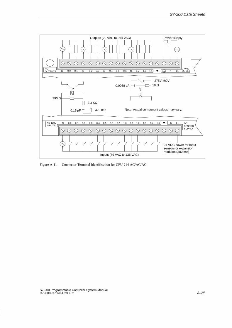
A-25S7-200 Programmable Controller System Manual C79000-G7076-C230-02
1L 0.0 0.1 2L 0.2 0.3 3L 0.4 N L1 85–264VAC
N 0.0 0.1 0.2 0.3 0.4 0.5 0.6 M L+0.7
Outputs (20 VAC to 264 VAC) Power supply
Inputs (79 VAC to 135 VAC)
24 VDC power for inputsensors or expansionmodules (280 mA)
10 Ω0.0068 µF
275V MOV
0.15 µF 470 KΩ
390 Ω
ACOUTPUTS
DCSENSORSUPPLY
AC 120VINPUTS
3.3 KΩ
0.5 0.6 4L 0.7 1.0 1.1
1.0 1.1 1.2 1.3 1.4 1.5
Note: Actual component values may vary.
Figure A-11 Connector Terminal Identification for CPU 214 AC/AC/AC
S7-200 Data Sheets

A-26S7-200 Programmable Controller System Manual
C79000-G7076-C230-02
A.12 CPU 214 AC Power Supply, Sourcing DC Inputs, Relay Outputs
Order Number: 6ES7 214-1BC10-0XB0General Features
Physical size (L x W x D) 197 x 80 x 62 mm (7.76 x 3.15 x 2.44 in.)
Weight 0.5 kg (1.0 lbs.)
Power dissipation 9 W
User program size/storage 2 Kwords/EEPROM
User data size/storage 2 Kwords/RAM
Data and TOD retention Supercap
Optional battery
190 hr typ. (120 hr minimum at 40° C)200 days continuous usage
Local I/O1 14 inputs/10 outputs
Max. I/O expansion modules 7
Digital I/O supported 64 inputs/64 outputs
Analog I/O supported 16 inputs/16 outputs
Boolean execution speed 0.8 µs/instruction
Internal memory bits 256
Timers 128 timers
Counters 128 counters
High-speed counters 1 software (2 KHz max.)2 hardware (7 KHz max. ea.)
TOD clock tolerance 6 minutes per month
Pulse outputs Not recommended
Analog adjustments 2
Standards compliance UL 508 CSA C22.2 142FM Class I, Division 2VDE 0160 compliantCE compliant
Input Points
Type Sourcing
Input voltage range 15 to 30 VDC, 35 VDC for 500 ms
ON state 4 mA minimum
OFF state 1 mA maximum
Maximum response timeI0.0 to I1.5
I0.6 to I1.5 as used by HSC1 and HSC2
0.2 ms to 8.7 ms selectable0.2 ms default30 µs typical/70 µs max.
Optical isolation 500 VAC, 1 min
Output Points
Output type Relay, dry contact
Voltage range 5 to 30 VDC/250 VAC
Maximum load current 2 A /point, 8 A/common
Overcurrent surge 7 A with contacts closed
Isolation resistance 100 M minimum (new)
Switching delay 10 ms maximum
Lifetime 10,000,000 mechanical100,000 with rated load
Contact resistance 200 m maximum (new)
IsolationCoil to contactContact to contact(Between open contacts)
1500 VAC, 1 min750 VAC, 1 min
Short circuit protection None
Power Supply
Voltage/frequency range 85 to 264 VAC at 47 to 63 Hz
Input current 4.5 VA typical, CPU only50 VA max. load
Holdup time 20 ms min. from 110 VAC
Inrush current 20 A peak at 264 VAC
Fusing (non-replaceable) 2 A, 250 V, slow blow
5 VDC current 340 mA for CPU660 mA for expansion I/O
Isolated Yes. Transformer, 1500 VAC,1 min
DC Sensor Supply
Voltage range 20.4 to 28.8 VDC
Ripple/noise (<10MHz) 1 V peak-to-peak maximum
24 VDC available current 280 mA
Short circuit current limit < 600 mA
Isolated No
1 The CPU reserves 16 process-image input and 16 process-image output register points for local I/O.
S7-200 Data Sheets

A-27S7-200 Programmable Controller System Manual C79000-G7076-C230-02
Outputs (30 VDC/250 VAC)
Inputs (15 VDC to 30 VDC)
24 VDC power for inputsensors or expansionmodules (280 mA)
+ +
3.3 KΩ
470 Ω
Power supply
1L 0.0 0.1 0.2 0.3 2L 0.4 N L1 85–264VACRELAY
OUTPUTS 0.5 0.6 3L 0.7 1.0
1L 0.0 0.1 0.2 0.3 0.4 0.5 0.6 M L+0.7 DCSENSORSUPPLY
DC 24VINPUTS
2L 1.0 1.1 1.2 1.3 1.4 1.5
1.1
Note: 1. Actual component values may vary.2. Connect AC line to the L terminal.3. Input circuit ground is optional.
N (-)
L (+)
N (-)
L (+)
N (-)
L (+)
Figure A-12 Connector Terminal Identification for CPU 214 AC/Sourcing DC/Relay
S7-200 Data Sheets

A-28S7-200 Programmable Controller System Manual
C79000-G7076-C230-02
A.13 CPU 214 AC Power Supply, 24 VAC Inputs, AC Outputs
Order Number: 6ES7 214-1DC01-0XB0
General Features
Physical size (L x W x D) 197 x 80 x 62 mm (7.76 x 3.15 x 2.44 in.)
Weight 0.5 kg (1.0 lbs.)
Power dissipation 11 W at 4.25 A load
User program size/storage 2 Kwords/EEPROM
User data size/storage 2 Kwords/RAM
Data and TOD retention Supercap
Optional battery
190 hr typ. (120 hr minimum at 40° C)200 days continuous usage
Local I/O1 14 inputs/10 outputs
Max. I/O expansion modules 7
Digital I/O supported 64 inputs/64 outputs
Analog I/O supported 16 inputs/16 outputs
Boolean execution speed 0.8 µs/instruction
Internal memory bits 256
Timers 128 timers
Counters 128 counters
High-speed counters 1 software (50 Hz)2 hardware (50 Hz each)
TOD clock tolerance 6 minutes per month
Pulse outputs 2 (100 Hz each)
Analog adjustments 2
Standards compliance UL 508 CSA C22.2 142FM Class I, Division 2CE compliant
Input Points
Input type (IEC 1131-2) Type 1 sinking
ON state range 15 to 30 VAC, 47 to 63 Hz, 4 mA minimum
ON state nominal 24 VAC, 60 Hz, 7 mA
OFF state maximum 5 VAC, 1 mA
Maximum response time 0.2 ms to 8.7 ms selectableplus 15.0 ms for fixed filter15.2 ms default
Optical isolation 1500 VAC, 1 min
Output Points
Output type Triac, zero-crossing
Voltage/frequency range 20 to 264 VAC, 47 to 63 Hz
Load circuit power factor 0.3 to 1.0
Inductive load clamping MOV 275 V working voltage
Maximum load currentper single pointper 2 adjacent pointsall points total
0 to 40° C 55° C2
1.20 A 1.00 A1.50 A 1.25 A6.00 A 4.25 A
Minimum load current 30 mA
Leakage current 1.5 mA, 120 VAC/2.0 mA,240 VAC
Switching delay 1/2 cycle
Surge current 30 A peak, 1 cycle / 10 A peak, 5 cycle
Voltage drop 1.5 V maximum at maximumcurrent
Optical isolation 1500 VAC, 1 min
Short circuit protection None
Power Supply
Voltage/frequency range 85 to 264 VAC at 47 to 63 Hz
Input current 4.5 VA typical, CPU only50 VA maximum load
Holdup time 20 ms min. from 110 VAC
Inrush current 20 A peak at 264 VAC
Fusing (non-replaceable) 2 A, 250 V, slow blow
5 VDC available current 440 mA for CPU560 mA for expansion I/O
Isolated Yes. Transformer, 1500 VAC,1 min
DC Sensor Supply
Voltage range 20.4 to 28.8 VDC
Ripple/noise (<10MHz) <1 V peak-to-peak maximum
24 VDC available current 280 mA
Short circuit current limit < 600 mA
Isolated No
1 The CPU reserves 16 process-image input and 16 process-image output register points for local I/O.2 Linear derate 40 to 55° C. Vertical mount derate 10° C
S7-200 Data Sheets

A-29S7-200 Programmable Controller System Manual C79000-G7076-C230-02
1L 0.0 0.1 2L 0.2 0.3 3L 0.4 N L1 85–264VAC
N 0.0 0.1 0.2 0.3 0.4 0.5 0.6 M L+0.7
Outputs (20 VAC to 264 VAC) Power supply
Inputs (15 VAC to 30 VAC)
24 VDC power for inputsensors or expansionmodules (280 mA)
10 Ω0.0068 µF
275V MOV
390 Ω
ACOUTPUTS
DCSENSORSUPPLY
AC 24VINPUTS
3.3 KΩ
0.5 0.6 4L 0.7 1.0 1.1
1.0 1.1 1.2 1.3 1.4 1.5
Note: Actual component values may vary.
Figure A-13 Connector Terminal Identification for CPU 214 AC/AC/AC
S7-200 Data Sheets

A-30S7-200 Programmable Controller System Manual
C79000-G7076-C230-02
A.14 CPU 214 AC Power Supply, AC Inputs, Relay Outputs
Model Number: 6ES7 214-1GC01-0XB0
General Features
Physical Size (L x W x D) 197 x 80 x 62 mm (7.75 x 3.15 x 2.44 in.)
Weight 0.5 kg (1.0 lbs.)
Power Dissipation 9 W
User program size/storage 2K Words / EEPROM
User data size/storage 2K Words / RAM
Data and TOD Retention Supercap
Optional Battery
190 hr typ. (120 hr minimum at 40° C)200 days continuous usage
Local I/O1 14 Inputs / 10 Outputs
Max. I/O Expansion Modules 7
Digital I/O Supported 64 Inputs / 64 Outputs
Analog I/O Supported 16 Inputs / 16 Outputs
Boolean Execution Speed 0.8 µs/instruction
Internal Memory Bits 256
Timers 128 Timers
Counters 128 Counters
High-speed counters 1 Software (2 KHz max.)2 Hardware (7 KHz max. ea.)
TOD Clock Tolerance 6 minutes per month
Pulse Outputs Not recommended
Analog Adjustments 2
Standards Compliance UL 508 CSA C22.2 142FM Class I, Division 2VDE 0160 compliantCE compliant
Input Points
Input Type (IEC 1131-2) Type 1 Sinking
ON State Range 79 to 135 VAC, 47 to 63 Hz4 mA minimum
ON State Nominal 120 VAC, 60 Hz. 7mA
OFF State Maximum 20 VAC, 1 mA
Maximum Response Time
0.2 ms to 8.7 ms selectableplus 15.0 ms for fixed filter15.2 ms default
Optical Isolation 1500 VAC, 1 minute
Output Points
Output Type Relay, dry contact
Voltage Range 5 to 30 VDC / 250 VAC
Maximum Load Current 2 A/point
Overcurrent Surge 7 A with contacts closed
Isolation Resistance 100 M minimum (new)
Switching Delay 10 ms maximum
Lifetime 10,000,000 Mechanical100,000 with Rated Load
Contact Resistance 200 m maximum (new)
IsolationCoil to ContactContact to Contact
1500 VAC, 1 minute1000 VAC, 1 minute
Short Circuit Protection None
Power Supply
Voltage / Frequency Range 85 to 264 VAC at 47 to 63 Hz
Input Current 4.5 VA typical, CPU only50 VA max. load
Hold Up Time 20 ms min. from 110VAC
Inrush Current 20 A peak at 264 VAC
Fusing (non-replaceable) 2 A, 250 V, Slow Blow
5 VDC Current 340 mA for CPU660 mA for expansion I/O
Isolated Yes. Transformer, 1500 VAC,1 minute
DC Sensor Supply
Voltage Range 20.4 to 28.8 VDC
Ripple/noise (<10Mhz) 1 V peak-to-peak maximum
24 VDC Available Current 280 mA
Short Circuit Current Limit < 600 mA
Isolated No
1 The CPU reserves 16 input and 16 output image register points for local I/O.
S7-200 Data Sheets

A-31S7-200 Programmable Controller System Manual C79000-G7076-C230-02
Outputs (30 VDC / 250 VAC) Power Supply
1L 0.0 0.1 0.2 0.3 2L 0.4 N L1 85–264VACRELAY
OUTPUTS 0.5 0.6 3L 0.7 1.0 1.1
N (-)
L (+)
N (-)
L (+)
N (-)
L (+)
N 0.0 0.1 0.2 0.3 0.4 0.5 0.6 M L+0.7
Inputs (79 to 135 VAC)
24 VDC Power for InputSensors or ExpansionModules (280 mA)
0.15 µF 470K ohms
390 ohms
DCSENSORSUPPLY
AC 120VINPUTS
3.3K ohms
1.0 1.1 1.2 1.3 1.4 1.5
Note: Actual component values may vary.
Figure A-14 Connector Terminal Identification for CPU 214 AC/AC/Relay
S7-200 Data Sheets

A-32S7-200 Programmable Controller System Manual
C79000-G7076-C230-02
A.15 CPU 215 DC Power Supply, DC Inputs, DC Outputs
Order Number: 6ES7 215-2AD00-0XB0
General Features
Physical size (L x W x D) 217.3 x 80 x 62 mm (8.56 x 3.15 x 2.44 in.)
Weight 0.5 kg (1.1 lbs.)
Power dissipation 8 W
User program size/storage 4 Kwords/EEPROM
User sata size/storage 2.5 Kwords/RAM
Data and TOD retention Supercap
Optional battery
190 hr typ. (120 hr minimum at 40° C)200 days continuous usage
Local I/O1 14 inputs/10 outputs
Max. I/O expansion modules 7
Digital I/O supported 64 inputs/64 outputs
Analog I/O supported 16 inputs/16 outputs
Boolean execution speed 0.8 µs/instruction
Internal memory bits 256
Timers 256 timers
Counters 256 counters
High-speed counters 1 software (2 KHz max.)2 hardware (20 KHz max. ea.)
TOD clock tolerance 6 minutes per month
Pulse outputs 2 (4 KHz max. each)
Analog adjustments 2
Standards compliance UL 508 CSA C22.2 142FM Class I, Division 2VDE 0160 compliantCE compliant
Input Points
Input type Sink/SourceIEC Type 1 in sink mode
ON state range 15 to 30 VDC, 4 mA min.35 VDC, 500 ms surge
ON state nominal 24 VDC, 7 mA
OFF state maximum 5 VDC, 1 mA
Maximum response timeI0.0 to I1.5
I0.6 to I1.5 as used byHSC1 and HSC2
0.2 ms to 8.7 ms selectable0.2 ms default6 µs ON, 30 µs OFF
Optical isolation 500 VAC, 1 min
Output Points
Output type Sourcing MOSFET
Voltage range 20.4 to 28.8 VDC
Maximum load currentQ0.0 to Q0.7Q1.0, Q1.1
Outputs may be connectedparallel for higher current
0 to 55° C0.5A/Point1.0A/Point
Leakage currentQ0.0 to Q0.7Q1.0, Q1.1
200 µA400 µA
Switching delay Q0.0, 0.1All others
100 µs, ON/OFF150 µs ON, 400 µs OFF
On resistance 400 mΩ max.
Short circuit protectionQ0.0 to Q0.7Q1.0, Q1.1
0.7 to 1.5 A/channel1.5 to 3A/channel
Optical isolation 500 VAC, 1 min
Power Supply
Voltage range 20.4 to 28.8 VDC
Input current 120 mA typical, CPU only1.3 A maximum load
UL/CSA rating 50VA
Holdup time 10 ms min. from 24 VDC
Inrush current 10 A peak at 28.8 VDC
Fusing (non-replaceable) 2 A, slow blow
5 VDC current 1000 mA for expansion I/O
Isolated No
DC Sensor Supply
Voltage range 16.4 VDC to 28.8 VDC
Ripple/noise (<10MHz) Same as supplied Voltage
24 VDC available current 400 mA
Short circuit current limit < 600 mA
Isolated No
5-V DP Communication Supply
5 VDC current: 90 mA, available at DP Port,pins 6-5, for DP Repeater
Isolation Transformer, 500 VAC, 1 min
1 The CPU reserves 16 process-image input and 16 process-image output register points for local I/O.
S7-200 Data Sheets

A-33S7-200 Programmable Controller System Manual C79000-G7076-C230-02
24 VDC power forinput sensors orexpansion modules(400 mA)
Outputs (20.4 VDC to 28.8 VDC) Power supply
+
M L+ 24VDC
OUT
DC 24VINPUTS
+
M L+DC 24VOUTPUTS
DC24V
+ + +
1M 0.0 0.1 0.2 0.3 0.4 0.5 0.6 0.7 2M 1.0 1.1 1.2 1.3 1.4 1.5
1M 1L+ 0.0 0.1 0.4 0.5 0.7 2M 2L+ 1.0 1.10.3 0.2 0.6
3.3 KΩ
470 Ω
Note: 1. Actual component values may vary.2. Either polarity accepted.3. DC circuit grounds are optional.
Figure A-15 Connector Terminal Identification for CPU 215 DC/DC/DC
S7-200 Data Sheets

A-34S7-200 Programmable Controller System Manual
C79000-G7076-C230-02
A.16 CPU 215 AC Power Supply, DC Inputs, Relay Outputs
Order Number: 6ES7 215-2BD00-0XB0
General Features
Physical size (L x W x D) 217.3 x 80 x 62 mm (8.56 x 3.15 x 2.44 in.)
Weight 0.6 kg (1.3 lbs.)
Power dissipation 9 W
User program size/storage 4 Kwords/EEPROM
User data size/storage 2.5 Kwords/RAM
Data and TOD retention Supercap
Optional battery
190 hr typ (120 hr min. at40°C)200 days continuous usage
Local I/O1 14 input/10 outputs
Max. I/O expansion modules 7
Digital I/O supported 64 input/64 outputs
Analog I/O supported 16 inputs/16 outputs
Boolean execution speed 0.8 µs/instruction
Internal memory bits 256
Timers 256 Timers
Counters 256 Counters
High-speed counters 1 software (2 KHz max.)2 hardware (20 KHz max. ea.)
TOD clock tolerance 6 minutes per month
Pulse outputs Not recommended
Analog adjustments 2
Standards compliance UL 508 CSA C22.2 142FM Class I, Division 2VDE 0160 compliantCE compliant
Input Points
Input type Sink/SourceIEC 1131 Type 1 in sink mode
ON state range 15 to 30 VDC, 4 mAminimum35 VDC, 500 ms surge
ON state nominal 24 VDC, 7 mA
OFF state maximum 5 VDC, 1 mA
Maximum response timeI0.0 to I1.5
I0.6 to I1.5 as used by HSC1 and HSC2
0.2 ms to 8.7 ms selectable0.2 ms default6 µs ON, 30 µs OFF
Output Points
Output type Relay, dry contact
Voltage range 5 VDC to 30 VDC/250 VAC
Maximum load current 2 A/point, 6 A/common
Overcurrent surge 7 A with contacts closed
Isolation resistance 100 M minimum (new)
Switching delay 10 ms maximum
Lifetime 10,000,000 mechanical100,000 with rated load
Contact resistance 200 m maximum (new)
IsolationCoil to contactContact to contact(Between open contacts)
1500 VAC, 1 min750 VAC, 1 min
Short circuit protection None
Power Supply
Voltage/frequency range 85 to 264 VAC at 47 to 63 Hz
Input current 6 VA typical, CPU only50 VA max. load
Holdup time 20 ms min. from 110 VAC
Inrush current 20 A peak at 264 VAC
Fusing (non-replaceable) 2 A, 250 V, Slow Blow
5 VDC current 1000 mA for expansion I/O
Isolated Yes. Transformer, 1500 VAC,1 min
DC Sensor Supply
Voltage range 19.2 to 28.8 VDC
Ripple/noise (<10MHz) 1 V peak-to-peak maximum
24 VDC available current 400 mA
Short circuit current limit < 600 mA
Isolated No
5-V DP Communication Supply
5 VDC current: 90 mA, available at DP Port,pins 6-5, for DP Repeater
Isolation Transformer, 500 VAC, 1 min
1 The CPU reserves 16 process-image input and 16 process-image output register points for local I/O.
S7-200 Data Sheets

A-35S7-200 Programmable Controller System Manual C79000-G7076-C230-02
24 VDC power forinput sensors orexpansionmodules (400 mA)
Outputs (30 VDC / 250 VAC)
Power Supply
+
1M 0.0 0.1 0.2 0.3 0.4 0.5 0.6 M L+0.7 24VDC
OUT
DC 24VINPUTS
2M 1.0 1.1 1.2 1.3 1.4 1.5
+
1L 0.0 0.1 0.2 0.3 0.4 N L1RELAYOUTPUTS 3L 0.5 0.6 4L 0.7 5L 1.0 6L 1.12L
VAC85-264
Inputs (15 VDC to 30 VDC)
3.3 KΩ
470 Ω
Note: 1. Actual component values may vary.2. Connect AC line to the L terminal.3. Either polarity accepted.4. DC circuit grounds are optional.
Figure A-16 Connector Terminal Identification for CPU 215 AC/DC/Relay
S7-200 Data Sheets

A-36S7-200 Programmable Controller System Manual
C79000-G7076-C230-02
A.17 CPU 216 DC Power Supply, DC Inputs, DC Outputs
Order Number: 6ES7 216-2AD00-0XB0
General Features
Physical size (L x W x D) 217.3 x 80 x 62 mm (8.56 x 3.15 x 2.44 in.)
Weight 0.5 kg (1.1 lbs.)
Power dissipation 8 W
User program size/storage 4 Kwords/EEPROM
User data size/storage 2.5 Kwords/RAM
Data and TOD retention Supercap
Optional battery
190 hr typ. (120 hr minimum at 40° C)200 days continuous usage
Local I/O1 24 inputs/16 outputs
Max. I/O expansion modules 7
Digital I/O supported 64 inputs/64 outputs
Analog I/O supported 16 inputs/16 outputs
Boolean execution speed 0.8 µs/instruction
Internal memory bits 256
Timers 256 timers
Counters 256 counters
High-speed counters 1 software (2 KHz max.)2 hardware (20 KHz max. ea.)
TOD clock tolerance 6 minutes per month
Pulse outputs 2 (4 KHz max. each)
Analog adjustments 2
Standards compliance UL 508 CSA C22.2 142FM Class I, Division 2VDE 0160 compliantCE compliant
Input Points
Input type Sink/SourceIEC 1131 Type 1 in sink mode
ON state range 15 to 30 VDC, 4 mA min.35 VDC, 500 ms surge
ON state nominal 24 VDC, 7 mA
OFF state maximum 5 VDC, 1 mA
Maximum response timeI0.0 to I1.5
I0.6 to I1.5 as used byHSC1 and HSC2
I1.6 to I2.7
0.2 ms to 8.7 ms selectable0.2 ms default6 µs ON, 30 µs OFF
4 ms max
Optical isolation 500 VAC, 1 min
Output Points
Output type Sourcing MOSFET
Voltage range 20.4 VDC to 28.8 VDC
Maximum load currentOutputs may be connectedparallel for higher current
0 to 55° C0.5A/Point
Leakage current 200 µA
Switching delay Q0.0, 0.1All others
100 µs, ON/OFF150 µs ON, 400 µs OFF
On resistance 400 mΩ max.
Short circuit protection 0.7 to 1.5 A/channel
Optical isolation 500 VAC, 1 min
Power Supply
Voltage range 20.4 VDC to 28.8 VDC
Input current 100 mA typical, CPU only1.2A maximum load
UL/CSA Rating 50VA
Holdup time 10 ms min. from 24 VDC
Inrush current 10 A peak at 28.8 VDC
Fusing (non-replaceable) 2 A, slow blow
5 VDC current 1000 mA for expansion I/O
Isolated No
DC Sensor Supply
Voltage range 16.4 VDC to 28.8 VDC
Ripple/noise (<10MHz) Same as supplied voltage
24 VDC available current 400 mA
Short circuit current limit < 600 mA
Isolated No
1 The CPU reserves 24 process-image input and 16 process-image output register points for local I/O.
S7-200 Data Sheets

A-37S7-200 Programmable Controller System Manual C79000-G7076-C230-02
Outputs (20.4 VDC to 28.8 VDC)
3.3 KΩ
470 Ω
Power supply
+
1M 0.0 0.1 0.2 0.3 0.4 0.5 0.6 M L+0.7 24VDC
OUT
DC 24VINPUTS
1.0 1.1 1.2 1.3 1.4 2M 1.5 1.6 1.7 2.0 2.1 2.2 2.3 2.4 2.5 2.6 2.7
+
1M 1L+ 0.0 0.1 0.2 0.4 0.5 M L+0.5DC 24VOUTPUTS 0.7 2M 2L+ 1.0 1.1 1.2 1.3 1.4 1.5 1.6 1.70.3
DC24V
+ + +
Note: 1. Actual component values may vary.2. Either polarity accepted.3. DC circuit grounds are optional.
24 VDC power forinput sensors orexpansionmodules (400 mA)
Inputs (15 VDC to 30 VDC)
Figure A-17 Connector Terminal Identification for CPU 216 DC/DC/DC
S7-200 Data Sheets

A-38S7-200 Programmable Controller System Manual
C79000-G7076-C230-02
A.18 CPU 216 AC Power Supply, DC Inputs, Relay Outputs
Order Number: 6ES7 216-2BD00-0XB0
General Features
Physical size (L x W x D) 217.3 x 80 x 62 mm (8.56 x 3.15 x 2.44 in.)
Weight 0.6 kg (1.3 lbs.)
Power dissipation 9 W
User program size/storage 4 Kwords/EEPROM
User data size/storage 2.5 Kwords/RAM
Data and TOD retention Supercap Optional battery
190 hr typ. (120 hr min. at 40°C)200 days continuous usage
Local I/O1 24 inputs/16 outputs
Max. I/O expansionmodules
7
Digital I/O supported 64 inputs/64 outputs
Analog I/O supported 16 inputs/16 outputs
Boolean execution speed 0.8 µs/instruction
Internal memory bits 256
Timers 256 timers
Counters 256 counters
High-speed counters 1 software (2 KHz max.)2 hardware (20 KHz max. ea.)
TOD clock tolerance 6 minutes per month
Pulse outputs Not recommended
Analog adjustments 2
Standards compliance UL 508 CSA C22.2 142FM Class I, Division 2VDE 0160 compliantCE compliant
Input Points
Input type Sink/SourceIEC Type 1131 in sink mode
ON state range 15 to 30 VDC, 4 mA minimum35 VDC, 500 ms surge
ON state nominal 24 VDC, 7 mA
OFF state maximum 5 VDC, 1 mA
Maximum response timeI0.0 to I1.5
I0.6 to I1.5 as used by HSC1 and HSC2
I1.6 to I2.7
0.2 ms to 8.7 ms selectable0.2 ms default6 µs ON, 30 µs OFF
4 ms maximum
Optical isolation 500 VAC, 1 min
Output Points
Output type Relay, dry contact
Voltage range 5 to 30 VDC/250 VAC
Maximum load current 2 A/point, 10 A/common
Overcurrent surge 7 A with contacts closed
Isolation resistance 100 M minimum (new)
Switching delay 10 ms maximum
Lifetime 10,000,000 mechanical100,000 with rated load
Contact resistance 200 m maximum (new)
IsolationCoil to contactContact to contact(Between open contacts)
1500 VAC, 1 min750 VAC, 1 min
Short circuit protection None
Power Supply
Voltage/frequency range 85 to 264 VAC at 47 to 63 Hz
Input current 6 VA typical, CPU only50 VA max. load
Holdup time 20 ms min. from 110 VAC
Inrush current 20 A peak at 264 VAC
Fusing (non-replaceable) 2 A, 250 V, Slow Blow
5 VDC current 1000 mA for expansion I/O
Isolated Yes. Transformer, 1500 VAC,1 min
DC Sensor Supply
Voltage range 19.2 VDC to 28.8 VDC
Ripple/noise (<10MHz) 1 V peak-to-peak maximum
24 VDC available current 400 mA
Short circuit current limit < 600 mA
Isolated No
1 The CPU reserves 24 process-image input and 16 process-image output register points for local I/O.
S7-200 Data Sheets

A-39S7-200 Programmable Controller System Manual C79000-G7076-C230-02
Outputs (30 VDC/250 VAC)
Inputs (15 VDC to 30 VDC)
24 VDC power forinput sensors orexpansion modules(400 mA)
+
3.3 KΩ470 Ω
Power supply
85–264VAC
Note: 1. Actual component values may vary.2. Connect AC line to the L terminal.3. Either polarity accepted.4. DC circuit grounds are optional.
N (-)
L (+)
1M 0.0 0.1 0.2 0.3 0.4 0.5 0.6 M L+0.7 24VDC
OUT
DC 24VINPUTS
1.0 1.1 1.2 1.3 1.4 2M 1.5 1.6 1.7 2.0 2.1 2.2 2.3 2.4 2.5 2.6 2.7
+
1L 0.0 0.1 0.2 0.3 2L 0.4 N L10.5RELAYOUTPUTS 0.6 0.7 1.0 3L 1.1 1.2 1.3 1.4 1.5 1.6 1.7
Figure A-18 Connector Terminal Identification for CPU 216 AC/DC/Relay
S7-200 Data Sheets

A-40S7-200 Programmable Controller System Manual
C79000-G7076-C230-02
A.19 Expansion Module EM221 Digital Input 8 x 24 VDC
Order Number: 6ES7 221-1BF00-0XA0
General Features
Physical size (L x W x D) 90 x 80 x 62 mm (3.54 x 3.15 x 2.44 in.)
Weight 0.2 kg (0.4 lbs.)
Power dissipation 2 W
Points1 8 digital inputs
Standards compliance UL 508 CSA C22.2 142FM Class I, Division 2VDE 0160 compliantCE compliant
Input Points
Input type Type 1 Sinking per IEC 1131-2
ON state range 15-30 VDC, 4 mA minimum35 VDC, 500 ms surge
ON state nominal 24 VDC, 7 mA
OFF state maximum 5 VDC, 1 mA
Response time 3.5 ms typical/4.5 ms max.
Optical isolation 500 VAC, 1 min
Current Requirements
5 VDC logic current 60 mA from base unit
24 VDC sensor current 60 mA from base unit orexternal power supply
1 The CPU reserves 8 process-image input register points for this module.
++
1M .0 .1 .2 2M.3 .4 .5
Inputs (15 VDC to 30 VDC)
.6 .7
Note: 1. Actual component values may vary.2. DC circuit grounds are optional.
3.3 KΩ
470 Ω
DC 24VINPUTS
Figure A-19 Connector Terminal Identification for EM221 Digital Input 8 x 24 VDC
S7-200 Data Sheets

A-41S7-200 Programmable Controller System Manual C79000-G7076-C230-02
A.20 Expansion Module EM221 Digital Input 8 x 120 VAC
Order Number: 6ES7 221-1EF00-0XA0
General Features
Physical size (L x W x D) 90 x 80 x 62 mm (3.54 x 3.15 x 2.44 in.)
Weight 0.2 kg (0.4 lbs.)
Power dissipation 2 W
Points1 8 digital inputs
Standards compliance UL 508 CSA C22.2 142FM Class I, Division 2CE compliant
Input Points
Input type Type 1 sinking per IEC 1131-2
ON state range 79 to 135 VAC, 47 to 63 Hz,4 mA minimum
ON state nominal 120 VAC, 60 Hz, 7 mA
OFF state maximum 20 VAC, 1 mA
Response time 15 ms maximum
Optical isolation 1500 VAC, 1 min
Current Requirements
5 VDC logic current 70 mA from base unit
1 The CPU reserves 8 process-image input register points for this module.
N .0 .1 .2 .5 .6 .7.3 .4
Note: Actual component values may vary.
AC 120VINPUTS
0.15 µF 470 KΩ
390 Ω3.3 KΩ
Inputs (79 VAC to 135 VAC)
Figure A-20 Connector Terminal Identification for EM221 Digital Input 8 x 120 VAC
S7-200 Data Sheets

A-42S7-200 Programmable Controller System Manual
C79000-G7076-C230-02
A.21 Expansion Module EM221 Digital Sourcing Input 8 x 24 VDC
Order Number: 6ES7 221-1BF10-0XA0
General Features
Physical size (L x W x D) 90 x 80 x 62 mm (3.54 x 3.15 x 2.44 in.)
Weight 0.2 kg (0.4 lbs.)
Power dissipation 2 W
Points1 8 digital inputs
Standards compliance UL 508 CSA C22.2 142FM Class I, Division 2VDE 0160 compliantCE compliant
Input Points
Type Sourcing
Input voltage range 15 VDC to 30 VDC, 35 VDCfor 500 ms.
ON state 4 mA minimum
OFF state 1 mA maximum
Response time 3.5 ms typical/4.5 ms max.
Optical isolation 500 VAC, 1 min
Current Requirements
5 VDC logic current 60 mA from base unit
24 VDC sensor current 60 mA from base unit orexternal power supply
1 The CPU reserves 8 process-image input register points for this module.
+
1L .0 .1 .2 2L.3 .4 .5
Inputs (15 VDC to 30 VDC)
.6 .7
Note: 1. Actual component values may vary.2. Input circuit ground is optional.
3.3 KΩ
470 Ω
DC 24VINPUTS
+
Figure A-21 Connector Terminal Identification for EM221 Digital Sourcing Input 8 x 24 VDC
S7-200 Data Sheets

A-43S7-200 Programmable Controller System Manual C79000-G7076-C230-02
A.22 Expansion Module EM221 Digital Input 8 x 24 VAC
Order Number: 6ES7 221-1JF00-0XA0
General Features
Physical size (L x W x D) 90 x 80 x 62 mm (3.54 x 3.15 x 2.44 in.)
Weight 0.2 kg (0.4 lbs.)
Power dissipation 2 W
Points1 8 digital inputs
Standards compliance(pending)
UL 508 CSA C22.2 142FM Class I, Division 2CE compliant
Input Points
Input type Type 1 sinking per IEC 1131-2
ON state range 15 to 30 VAC, 47 to 63 Hz,4 mA minimum
ON state nominal 24 VAC, 60 Hz, 7 mA
OFF state maximum 5 VAC, 1 mA
Response time 15 ms maximum
Optical isolation 1500 VAC, 1 min
Current Requirements
5 VDC logic current 70 mA from base unit
1 The CPU reserves 8 process-image input register points for this module.
N .0 .1 .2 .5 .6 .7.3 .4
Note: Actual component values may vary.
AC 24VINPUTS
390 Ω
3.3 KΩ
Inputs (15 VDC to 30 VAC)
Figure A-22 Connector Terminal Identification for EM221 Digital Input 8 x 24 VAC
S7-200 Data Sheets

A-44S7-200 Programmable Controller System Manual
C79000-G7076-C230-02
A.23 Expansion Module EM222 Digital Output 8 x 24 VDC
Order Number: 6ES7 222-1BF00-0XA0
General Features
Physical size (L x W x D) 90 x 80 x 62 mm (3.54 x 3.15 x 2.44 in.)
Weight 0.2 kg (0.4 lbs.)
Power dissipation 4 W at 3 A load
Points1 8 digital outputs
Standards compliance UL 508 CSA C22.2 142FM Class I, Division 2VDE 0160 compliantCE compliant
Output Points
Output type Sourcing transistor
Voltage range 20.4 VDC to 28.8 VDC
Maximum load currentper single pointper 2 adjacent pointsall points total
0 to 40° C 55° C2
0.75 A 0.50 A1.00 A 0.75 A4.00 A 3.00 A
Output Points (continued)
Inductive load clampingSingle Pulse
Repetitive
(per common)2A L/R = 10 ms1A L/R = 100 ms1 W energy dissipation(1/2 Li2 x switch rate 1 W)
Leakage current 100 µA
Switching delay 50 µs ON, 200 µs OFF
Surge current 4 A, 100 ms
Voltage drop 1.8 V maximum at maximumcurrent
Optical isolation 500 VAC, 1 min
Short circuit protection None
Current Requirements
5 VDC logic current 80 mA from base unit
Output point current Supplied by user at modulecommon
1 The CPU reserves 8 process-image output register points for this module.2 Linear derate 40 to 55° C. Vertical mount derate 10° C
+
1M 1L+ .0 .1 .2 2M 2L+ .4 .5.3 .6 .7
+
Outputs (20.4 to 28.8 VDC)
Note: 1. Actual component values may vary.2. DC circuit grounds are optional.
DC 24VOUTPUTS
36V
36V
Figure A-23 Connector Terminal Identification for EM222 Digital Output 8 x 24 VDC
S7-200 Data Sheets

A-45S7-200 Programmable Controller System Manual C79000-G7076-C230-02
A.24 Expansion Module EM222 Digital Output 8 x Relay
Order Number: 6ES7 222-1HF00-0XA0
General Features
Physical size (L x W x D) 90 x 80 x 62 mm (3.54 x 3.15 x 2.44 in.)
Weight 0.2 kg (0.4 lbs.)
Power dissipation 3 W
Points1 8 digital relay outputs
Standards compliance UL 508 CSA C22.2 142FM Class I, Division 2VDE 0160 compliantCE compliant
Output Points
Output type Relay, dry contact
Voltage range 5 to 30 VDC/250 VAC
Maximum load current 2 A/point, 8 A/common
Overcurrent surge 7 A with contacts closed
Isolation resistance 100 M minimum (new)
Output Points (continued)
Switching delay 10 ms maximum
Lifetime 10,000,000 mechanical100,000 with rated load
Contact resistance 200 mmaximum (new)
IsolationCoil to contactContact to contact(between open contacts)
1500 VAC, 1 min750 VAC, 1 min
Short circuit protection None
Current Requirements
5 VDC logic current 80 mA from base unit
24 VDC coil current 85 mA from base unit orexternal power supply
Output point current Supplied by user at modulecommon
1 The CPU reserves 8 process-image output register points for this module.
M L+ 1L .0 2L .4 .5
+
.1 .6 .7.2 .3
Note: 1. Actual component values may vary.2. Connect AC line to the L terminal.3. DC circuit grounds are optional.
RELAYOUTPUTS
Outputs (30 VDC/250 VAC)
24-VDCRelay coil
N (-)
L (+)
N (-)
L (+)
Figure A-24 Connector Terminal Identification for EM222 Digital Output 8 x Relay
S7-200 Data Sheets

A-46S7-200 Programmable Controller System Manual
C79000-G7076-C230-02
A.25 Expansion Module EM222 Digital Output 8 x 120/230 VAC
Order Number: 6ES7 222-1EF00-0XA0
General Features
Physical size (L x W x D) 90 x 80 x 62 mm (3.54 x 3.15 x 2.44 in.)
Weight 0.2 kg (0.4 lbs.)
Power dissipation 5 W at 3.5 A load
Points1 8 digital outputs
Standards compliance UL 508 CSA C22.2 142FM Class I, Division 2CE compliant
Output Points
Output type Triac, zero-cross turn on
Voltage/frequency range 20 to 264 VAC, 47 to 63 Hz
Load circuit power factor 0.3 to 1.0
Maximum load currentper single pointper 2 adjacent pointsall points total
0 to 40° C 55° C2
1.20 A 1.00 A1.50 A 1.25 A4.75 A 3.50 A
Output Points (continued)
Minimum load current 30 mA
Leakage current 1.5 mA, 120 VAC/2.0 mA,240 VAC
Switching delay 1/2 cycle
Surge current 30 A peak 1 cycle, 10 A peak 5 cycle
Voltage drop 1.5 V maximum at maximumcurrent
Optical isolation 1500 VAC, 1 min
Short circuit protection None
Current Requirements
5 VDC logic current 120 mA from base unit
Output point current Supplied by user at modulecommon
1 The CPU reserves 8 process-image output register points for this module.2 Linear derate 40 to 55° C. Vertical mount derate 10° C
S7-200 Data Sheets

A-47S7-200 Programmable Controller System Manual C79000-G7076-C230-02
1L .0 .1 2L .2 3L .4 .5.3 4L .6
Outputs (20 to 264 VAC)
.7ACOUTPUTS
Note: Actual component values may vary.
10 Ω0.0068 µF
275V MOV
Figure A-25 Connector Terminal Identification for EM222 Digital Output 8 x 120/230 VAC
S7-200 Data Sheets

A-48S7-200 Programmable Controller System Manual
C79000-G7076-C230-02
A.26 Expansion Module EM223 Digital Combination 4 x 24 VDC Input/4 x 24 VDC Output
Order Number: 6ES7 223-1BF00-0XA0General Features
Physical size (L x W x D) 90 x 80 x 62 mm (3.54 x 3.15 x 2.44 in.)
Weight 0.2 kg (0.4 lbs.)
Power dissipation 3.5 W at 3 A load
Points1 4 digital inputs4 digital outputs
Standards compliance UL 508 CSA C22.2 142FM Class I, Division 2VDE 0160 compliantCE compliant
Output Points
Output type Sourcing transistor(P-Channel MOSFET)
Voltage range 20.4 to 28.8 VDC
ON state resistance 400 mmaximum
Maximum load currentper single pointall points total
*Linear derate 40 to 55° C Vertical mount derate 10° C (Two points can be connected in parallel to serve a high current load.)
0 to 40° C 55° C*2.50 A 2.00 A4.00 A 3.00 A
Inductive load clampingSingle Pulse
Repetitive
(per common)2A L/R = 10 ms1A L/R = 100 ms1 W energy dissipation(1/2 Li2 x switch rate 1 W)
Output Points (continued)
Leakage current 1 µA maximum
Switching delay 25 µs ON, 120 µs OFF max.
Surge current 7 A, 100 ms
Optical isolation 500 VAC, 1 min
Short circuit protection None
Input Points
Input type Type 1 Sinking per IEC 1131-2
ON state range 15-30 VDC, 4 mA minimum35 VDC, 500 ms surge
ON state nominal 24 VDC, 7 mA
OFF state maximum 5 VDC, 1 mA
Response time 3.5 ms typical/4.5 msmaximum
Optical isolation 500 VAC, 1 min
Current Requirements
5 VDC logic current 80 mA from base unit
24 VDC sensor current 30 mA from base unit orexternal power supply
Output point current Supplied by user at modulecommon
1 The CPU reserves 8 process-image input and 8 process-image output register points for this module.
S7-200 Data Sheets

A-49S7-200 Programmable Controller System Manual C79000-G7076-C230-02
+
+
1M .0 .1 .2 .3 2M
Inputs (15 to 30 VDC)
L+ .0
Note: 1. Actual component values may vary2. DC circuit grounds are optional.
3.3 KΩ470 Ω
DC/DCIN-OUT .1 .2 .3
36V
36V
Outputs (20.4 to 28.8 VDC)
Figure A-26 Connector Terminal Identification for EM223 Digital Combination 4 x 24 VDC Input/4 x 24 VDCOutput
S7-200 Data Sheets

A-50S7-200 Programmable Controller System Manual
C79000-G7076-C230-02
A.27 Expansion Module EM223 Digital Combination 8 x 24 VDC Input/8 x 24 VDC Output
Order Number: 6ES7 223-1BH00-0XA0General Features
Physical size (L x W x D) 90 x 80 x 62 mm (3.54 x 3.15 x 2.44 in.)
Weight 0.2 kg (0.44 lbs.)
Power dissipation 3.0 W
Points1 8 digital inputs8 digital outputs
Standards compliance UL 508 CSA C22.2 142FM Class I, Division 2VDE 0160 compliantCE compliant
Output Points
Output type Sourcing MOSFET
Voltage range 20.4 VDC to 28.8 VDC
Maximum load currentOutputs may be connectedparallel for higher current
0 to 55 C0.5 A/Point
Leakage current 200 µΑ
Switching delay 150 µs ON, 400 µs OFF
On resistance 400 mΩ maximum
Short circuit protection 0.7 to 1.5 A/channel
Optical isolation 500 VAC, 1 min
Input Points
Input Type Sink/SourceIEC 1131 Type 1 in sinkmode
ON State Range 15 to 30 VDC, 4 mAminimum35 VDC, 500 ms surge
ON State Nominal 24 VDC, 7 mA
OFF State Maximum 5 VDC, 1 mA
Response Time 4.0 msmaximum
Optical Isolation 500 VAC, 1 min
Current Requirements
5 VDC logic current 120 mA from base unit
24 VDC sensor current 60 mA from base unit orexternal power supply
Output point current Supplied by user at modulecommon
1 The CPU reserves 8 process-image input and 8 process-image output register points for this module.
S7-200 Data Sheets

A-51S7-200 Programmable Controller System Manual C79000-G7076-C230-02
Outputs (20.4 - 28.8 VDC)
1M .0 .1 .2 .3 DCINPUTS
1M 1L .2 .3DCOUTPUTS 2L .4 .5 .6 .7.1
.0
Inputs (15 - 30 VDC)
3.3 KΩ
Note: 1. Actual component values may vary.2. Either polarity accepted3. Optional ground.
+
+
2M .4 .5 .6 .7
+ +
2M
470 Ω
Figure A-27 Connector Terminal Identification for EM223 Digital Combination 8 x 24 VDC Inputs/8 x 24 VDCOutputs
S7-200 Data Sheets

A-52S7-200 Programmable Controller System Manual
C79000-G7076-C230-02
A.28 Expansion Module EM223 Digital Combination 16 x 24 VDC Input/16 x 24 VDC Output
Order Number: 6ES7 223-1BL00-0XA0General Features
Physical size (L x W x D) 160 x 80 x 62 mm (6.30 x 3.15 x 2.44 in.)
Weight 0.4 kg (0.9 lbs.)
Power dissipation 5.5 W
Points1 16 Digital inputs16 Digital outputs
Standards compliance UL 508 CSA C22.2 142FM Class I, Division 2VDE 0160 compliantCE compliant
Output Points
Output type Sourcing MOSFET
Voltage range 20.4 VDC to 28.8 VDC
Maximum load currentOutputs may be connectedparallel for higher current
0 to 55 C0.5 A/Point
Leakage current 200 µΑ
Switching delay 150 µs ON, 400 µs OFF
On resistance 400 mΩ maximum
Short circuit protection 0.7 to 1.5 A/channel
Optical isolation 500 VAC, 1 minute
Input Points
Input type Sink/SourceIEC 1131 Type 1 in sinkmode
ON state range 15 to 30 VDC, 4 mAminimum35 VDC, 500 ms surge
ON state nominal 24 VDC, 7 mA
OFF state maximum 5 VDC, 1 mA
Response time 4.0 ms maximum
Optical isolation 500 VAC, 1 minute
Current Requirements
5 VDC logic current 210 mA from base unit
24 VDC sensor current 120 mA from base unit orexternal power supply
Output point current Supplied by user at modulecommon
1 The CPU reserves 16 process-image input and 16 process-image output register points for this module.
S7-200 Data Sheets

A-53S7-200 Programmable Controller System Manual C79000-G7076-C230-02
+
Outputs (20.4 - 28.8 VDC)
1M .0 .1 .2 .3 .4 .5 .6 .7 DCINPUTS
x.1 x.2 x.3 x.4 x.5 x.6 x.7
1M 1L .2 .3DCOUTPUTS 2L .4 .5 .6 .7.1
.0
Inputs (15 - 30 VDC)
3.3K Ω470 Ω
Note: 1. Actual component values may
vary.2. Either polarity accepted3. Optional ground.
++
2M x.0
3L x.0 x.1 x.2 x.3 x.4 x.5 x.6 x.7
+ +
2M 3M
Figure A-28 Connector Terminal Identification for EM223 Digital Combination 16 x 24 VDC Inputs/16 x 24 VDCOutputs
S7-200 Data Sheets

A-54S7-200 Programmable Controller System Manual
C79000-G7076-C230-02
A.29 Expansion Module EM223 Digital Combination 4 x 24 VDC Input/4 x Relay Output
Order Number: 6ES7 223-1HF00-0XA0General Features
Physical size (L x W x D) 90 x 80 x 62 mm (3.54 x 3.15 x 2.44 in.)
Weight 0.2 kg (0.4 lbs.)
Power dissipation 2 W
Points1 4 digital inputs4 digital relay outputs
Standards compliance UL 508 CSA C22.2 142FM Class I, Division 2VDE 0160 compliantCE compliant
Output Points
Output type Relay, dry contact
Voltage range 5 to 30 VDC/250 VAC
Maximum load current 2 A/Point
Isolation resistance 100 Mmaximum (new)
Switching delay 10 ms maximum
Lifetime 10,000,000 mechanical100,000 with rated load
IsolationCoil to contactContact to contact(between open contacts)
1500 VAC, 1 min750 VAC, 1 min
Output Points (continued)
Contact resistance 200 mmaximum (new)
Short circuit protection None
Input Points
Input type Type 1 Sinking per IEC 1131-2
ON state range 15 to 30 VDC, 4 mA min.35 VDC, 500 ms surge
ON state nominal 24 VDC, 7 mA
OFF state maximum 5 VDC, 1 mA
Response time 3.5 ms typical / 4.5 msmaximum
Optical isolation 500 VAC, 1 min
Current Requirements
5 VDC Logic current 80 mA from base unit
24 VDC Sensor current 30 mA from base unit orexternal power supply
24 VDC Coil current 35 mA from base unit orexternal power supply
Output point current Supplied by user at modulecommon
1 The CPU reserves 8 process-image input and 8 process-image output register points for this module.
+
+
1M .0 .1 .2 .3 2M
Inputs (15 VDC to 30 VDC)
L+ .0
3.3 KΩ
470 Ω
DC/RLYIN - OUT .1 .2 .3L
N (-)
L (+)
Note: 1. Actual component values may vary.2. Connect AC line to the L terminal.3. DC circuit grounds are optional.
Outputs (5 to 30 VDC/250 VAC)24 VDC Relay Coil
Figure A-29 Connector Terminal Identification for EM223 Digital Combination 4 x 24 VDC Input/4 x RelayOutput
S7-200 Data Sheets

A-55S7-200 Programmable Controller System Manual C79000-G7076-C230-02
A.30 Expansion Module EM223 Digital Combination 4 x 120 VAC Input/4 x 120 VAC to 230 VAC Output
Order Number: 6ES7 223-1EF00-0XA0General Features
Physical size (L x W x D) 90 x 80 x 62 mm (3.54 x 3.15 x 2.44 in.)
Weight 0.2 kg (0.4 lbs.)
Power dissipation 5.5 W at 3 A load
Points1 4 digital inputs4 digital outputs
Standards compliance UL 508 CSA C22.2 142FM Class I, Division 2CE compliant
Output Points
Output type Triac, zero-cross turn on
Voltage/frequency range 70 to 264 VAC, 47 to 63 Hz
Load circuit power factor 0.3 to 1.0
Maximum load currentper single pointall points total
0 to 40° C 55° C2
2.40 A 2.00 A4.00 A 3.00 A
Minimum load current 10 mA
Leakage current 2.5 mA, 120 V4.0 mA, 230 V
Switching delay 1/2 cycle
Output Points (continued)
Surge current 50 A peak, 1 cycle15 A peak, 5 cycle
Voltage drop 1.8 V maximum at maximumcurrent
Optical isolation 1500 VAC, 1 min
Short circuit protection None
Input Points
Input type Type 1 Sinking perIEC 1131-2
ON state range 79 to 135 VAC, 47 to 63 Hz4 mA minimum
ON state nominal 120 VAC, 60 Hz, 7 mA
OFF state maximum 20 VAC, 1 mA
Response time 15 ms maximum
Optical isolation 1500 VAC, 1 min
Current Requirements
5 VDC logic current 100 mA from base unit
Output point current Supplied by user at modulecommon
1 The CPU reserves 8 process-image input and 8 output process-image register points for this module.2 Linear derate 40 to 55° C. Vertical mount derate 10° C
N .0 .1 .2 .3
Inputs (79 to 135 VAC)
L .0
Note: Actual component values may vary.
AC/ACIN - OUT .1 .2 .3
Outputs (70 to 264 VAC)
10 Ω0.022 µF0.15 µF 470 KΩ
390 Ω3.3 KΩ
Figure A-30 Connector Terminal Identification for EM223 Digital 4 x 120 VAC Input/4 x 120 VAC to 230 VAC Output
S7-200 Data Sheets

A-56S7-200 Programmable Controller System Manual
C79000-G7076-C230-02
A.31 Expansion Module EM223 Digital Combination 8 x 24 VDC Input/8 x Relay Output
Order Number: 6ES7 223-1PH00-0XA0General Features
Physical size (L x W x D) 90 x 80 x 62 mm (3.54 x 3.15 x 2.44 in.)
Weight 0.3 kg (0.7 lbs.)
Power dissipation 2.5 W
Points1 8 digital inputs8 digital outputs
Standards compliance UL 508 CSA C22.2 142FM Class I, Division 2VDE 0160 compliantCE compliant
Output Points
Output type Relay, dry contact
Voltage range 5 to 30 VDC/250 VAC
Maximum load current 2 A /point, 8 A/common
Isolation resistance 100 MΩ maximum (new)
Switching delay 10 ms maximum
Lifetime 10,000,000 mechanical100,000 with rated load
Contact resistance 200 mΩ maximum (new)
IsolationCoil to contactContact to contact(Between open contacts)
1500 VAC, 1 min750 VAC, 1 min
Short circuit protection None
Input Points
Input Type Sink/SourceIEC 1131 Type 1 in sinkmode
ON State Range 15 to 30 VDC, 4 mAminimum35 VDC, 500 ms surge
ON State Nominal 24 VDC, 7 mA
OFF State Maximum 5 VDC, 1 mA
Response Time 4.0 msmaximum
Optical Isolation 500 VAC, 1 min
Current Requirements
5 VDC logic current 100 mA from base unit
24 VDC sensor current 90 mA from base unit orexternal power supply
Output point current Supplied by user at modulecommon
1 The CPU reserves 8 process-image input and 8 process-image output register points for this module.
S7-200 Data Sheets

A-57S7-200 Programmable Controller System Manual C79000-G7076-C230-02
DCINPUTS
Outputs (30 VDC/250 VAC)
1M .0 .1 .2 .3
+
M L+ 1L .2 .3RELAYOUTPUTS 2L .4 .5 .6 .7.1
.0
Inputs (15 to 30 VDC)
3.3 KΩ470 Ω
Note: 1. Actual component values may vary.2. Either polarity accepted3. DC circuit grounds are optional.4. Relay coil power M must connect to
sensor supply M of CPU.
24 VDC
+
+
2M .4 .5 .6 .7
Figure A-31 Connector Terminal Identification for EM223 Digital 8 x 24 VDC Input/8 x Relay Output
S7-200 Data Sheets

A-58S7-200 Programmable Controller System Manual
C79000-G7076-C230-02
A.32 Expansion Module EM223 Digital Combination 16 x 24 VDC Input/16 x Relay Output
Order Number: 6ES7 223-1PL00-0XA0General Features
Physical size (L x W x D) 160 x 80 x 62 mm (6.30 x 3.15 x 2.44 in.)
Weight 0.45 kg (1.0 lbs.)
Power dissipation 7 W
Points1 16 Digital inputs16 Digital relay outputs
Standards compliance UL 508 CSA C22.2 142FM Class I, Division 2VDE 0160 compliantCE compliant
Output Points
Output type Relay, dry contact
Voltage range 5 to 30 VDC/250 VAC
Maximum load current 2 A/point, 8 A/common
Isolation resistance 100 MΩ maximum (new)
Switching delay 10 ms maximum
Lifetime 10,000,000 Mechanical100,000 with rated load
Contact resistance 200 mΩ maximum (new)
IsolationCoil to contactContact to contact(between open contacts)
1500 VAC, 1 min750 VAC, 1 min
Short circuit protection None
Input Points
Input type Sink/SourceIEC 1131 Type 1 in sinkmode
ON state range 15 to 30 VDC, 4 mAminimum35 VDC, 500 ms surge
ON state nominal 24 VDC, 7 mA
OFF state maximum 5 VDC, 1 mA
Response time 3.5 ms typical/4.5 msmaximum
Optical isolation 500 VAC, 1 minute
Current Requirements
5 VDC logic current 160 mA from base unit
24 VDC sensor current 120 mA from base unit orexternal power supply
24 VDC coil current2 130 mA from base unit orexternal power supply
Output point current Supplied by user at modulecommon
1 The CPU reserves 16 process-image input and 16 process-image output register points for this module.2 Coil power must connect to common sensor supply M on the CPU.
S7-200 Data Sheets

A-59S7-200 Programmable Controller System Manual C79000-G7076-C230-02
Outputs (30 VDC/250 VAC)
1M .0 .1 .2 .3 .4 .5 .6 .7 DCINPUTS
x.1 x.2 x.3 x.4 x.5 x.6 x.7
+
M L+ 1L .2 .3RELAYOUTPUTS 2L .4 .5 .6 .7.1
.0
Inputs (15 to 30 VDC)
3.3K Ω470 Ω
Note: 1. Actual component values may
vary.2. Either polarity accepted3. DC circuit grounds are optional.4. Relay coil power M must connect
to sensor supply M of CPU.
24 VDC
++
2M x.0
3L x.0 x.1 x.2 x.3 4L x.4 x.5 x.6 x.7
To Coils
Figure A-32 Connector Terminal Identification for EM223 Digital Combination 16 x 24 VDC Input/16 x Relay Output
S7-200 Data Sheets

A-60S7-200 Programmable Controller System Manual
C79000-G7076-C230-02
A.33 Expansion Module EM231 Analog Input AI 3 x 12 Bits
Order Number: 6ES7 231-0HC00-0XA0
General Features
Physical size (L x W x D) 90 x 80 x 62 mm(3.54 x 3.15 x 2.44 in)
Weight 0.2 kg (0.4 lbs.)
Power dissipation 2 W
Points1 3 Analog inputs
Standards compliance UL 508 CSA C22.2 142FM Class I, Division 2VDE 0160 compliantCE compliant
Input Points
Input type Differential
Input impedance 10 MΩ
Input filter attenuation -3 db @ 3.1 kHz
Maximum input voltage 30 V
Maximum input current 32 mA
Resolution 12 bit A/D converter
Isolation Non-isolated
Input Points (continued)
Analog-to-digital conversion time < 250 µs
Analog step response 1.5 ms to 95%
Common mode rejection 40 dB, DC to 60 Hz
Common mode voltage Signal voltage plus commonmode voltage, less than orequal to 12 V
Data word format2
Unipolar, full-scale range 0 to 32000
Current Requirements
5 VDC logic current 70 mA from base unit
External power supply 60 mA from base unit orexternal power supply(24 VDC nominal, Class 2or DC sensor supply)
Indicator LED, EXTF
Power Supply Fault Low voltage, on external24 VDC
1 The CPU reserves 4 analog input points for this module.2 Data Word increments in 8 count steps, left justified values. See Figure A-35.
RA A+ A – RB B+ANALOGIN - PS L+ MB – RC C+ C –
EM231AI 3 x 12 Bit
EXTF
Voltage transmitter
Current transmitter
Unusedinput
24V
+ -
+
-
Figure A-33 Connector Terminal Identification for Expansion Module EM231 Analog Input AI 3 x 12 Bits
S7-200 Data Sheets

A-61S7-200 Programmable Controller System Manual C79000-G7076-C230-02
Calibration and Configuration Location
The calibration potentiometer and configuration DIP switches are accessed through theventilation slots of the module, as shown in Figure A-34.
Expansion module
Gain
OFFON
1 2 3 4
Figure A-34 Calibration Potentiometer and Configuration DIP Switches
Configuration
Table A-2 shows how to configure the module using the configuration DIP switches.Switches 1 and 3 select the analog input range. All inputs are set to the same analog inputrange.
Table A-2 Configuration Switch Table for EM231 Analog Input
Configuration SwitchFull Scale Input Resolution
1 3Full-Scale Input Resolution
ON OFF 0 to 5 V 1.25 mV
ON OFF 0 to 20 mA1 5 µA
OFF ON 0 to 10 V 2.5 mV
1 0 to 20 mA measurements were made using the internal 250-Ω current-sense resistor.
S7-200 Data Sheets

A-62S7-200 Programmable Controller System Manual
C79000-G7076-C230-02
Input Calibration
The module calibration is used to correct the gain error at full scale. Offset error is notcompensated. The calibration affects all three input channels, and there may be a differencein the readings between channels after calibration.
To calibrate the module accurately, you must use a program designed to average the valuesread from the module. Use the Analog Input Filtering wizard provided in STEP 7-Micro/WINto create this program (see Section 5.3). Use 64 or more samples to calculate the averagevalue.
To calibrate the input, use the following steps.
1. Turn off the power to the module. Select the desired input range.
2. Turn on the power to the CPU and module. Allow the module to stabilize for 15 minutes.
3. Using a transmitter, a voltage source, or a current source, apply a zero value signal toone of the input terminals.
4. Read the value reported to the CPU by the appropriate input channel. The reading with azero value input indicates the magnitude of the offset error. This error cannot becorrected by calibration.
5. Connect a full-scale value signal to one of the input terminals. Read the value reportedto the CPU.
6. Adjust the GAIN potentiometer until the reading is 32,000, or the desired digital datavalue.
Data Word Format
Figure A-35 shows where the 12-bit data value is placed within the analog input word of theCPU.
A variance in repeatability of only ±0.45% of full scale can give a variance of ±144 counts inthe value read from the analog input.
15 3MSB LSB
0AIW XX
0
0 0 0
214
Data value 12 Bits
Unipolar data
Figure A-35 Data Word Format
NoteThe 12 bits of the analog-to-digital converter (ADC) readings are left-justified in the dataword format. The MSB is the sign bit: zero indicates a positive data word value. The threetrailing zeros cause the data word to change by a count of eight for each one countchange in the ADC value.
S7-200 Data Sheets

A-63S7-200 Programmable Controller System Manual C79000-G7076-C230-02
Input Block Diagram
Figure A-36 shows the EM231 input block diagram.
R
RC
CC
A+
RA
A-
Rloop
R
RC
CC
B+
RB
B-
Rloop
R
RC
CC
C+
RC
C-
Rloop
A=0
A=1
A=2
A=3
Buffer
+
- R
R
R
R
R
Input differential andcommon-mode filter Input selector
SW3
SW1
Attenuation stage
xGAIN
DATADATA011
VrefA/D Converter
Analog-to-digital converter
Gain stage
Gain x1
AGND
Figure A-36 EM231 Input Block Diagram
S7-200 Data Sheets

A-64S7-200 Programmable Controller System Manual
C79000-G7076-C230-02
Installation Guidelines for EM231
Use the following guidelines to ensure accuracy and repeatability:
Ensure that the 24-VDC Sensor Supply is free of noise and is stable.
Calibrate the module.
Use the shortest possible sensor wires.
Use shielded twisted pair wiring for sensor wires.
Terminate the shield at the sensor location only.
Short the inputs for any unused channels, as shown in Figure A-33.
Avoid bending the wires into sharp angles.
Use wireways for wire routing.
Ensure that input signals are floating or referenced to the external 24V common of theanalog module.
Understanding and Using the Analog Input Module: Accuracy and Repeatability
The EM231 analog input module is a low-cost, high-speed 12 bit analog input module. Themodule is capable of converting an analog input to its corresponding digital value in171 µsec for the CPU 212 and 139 µsec for all other S7-200 CPUs. Conversion of theanalog signal input is performed each time the analog point is accessed by your program.These times must be added to the basic execution time of the instruction used to access theanalog input.
The EM231 provides an unprocessed digital value (no linearization or filtering) thatcorresponds to the analog voltage or current presented at the module’s input terminals.Since the module is a high-speed module, it can follow rapid changes in the analog inputsignal (including internal and external noise). Reading-to-reading variations caused by noisefor a constant or slowly changing analog input signal can be minimized by averaging anumber of readings. As the number of readings used in computing the average valueincreases, a correspondingly slower response time to changes in the input signal can beobserved.
You can use the STEP 7-Micro/WIN Analog Input Filtering wizard (see Section 5.3). to addan averaging routine to your program. Remember that an average value computed from alarge number of samples stabilizes the reading while slowing down its response to changesin the input signal. For slowly changing analog input signals, a sample size of 64 or greater isrecommended for the averaging routine.
The specifications for repeatability describe the reading-to-reading variations of the modulefor an input signal that is not changing. The repeatability specification defines the limits withinwhich 99% of the readings will fall. The mean accuracy specification describes the averagevalue of the error (the difference between the average value of individual readings and theexact value of the actual analog input signal). The repeatability is described in theFigure A-37 by the bell curve. This figure shows the 99% repeatability limits, the mean oraverage value of the individual readings, and the mean accuracy in a graphical form.Table A-3 gives the repeatability specifications and the mean accuracy as they relate to eachof the configurable ranges.
S7-200 Data Sheets
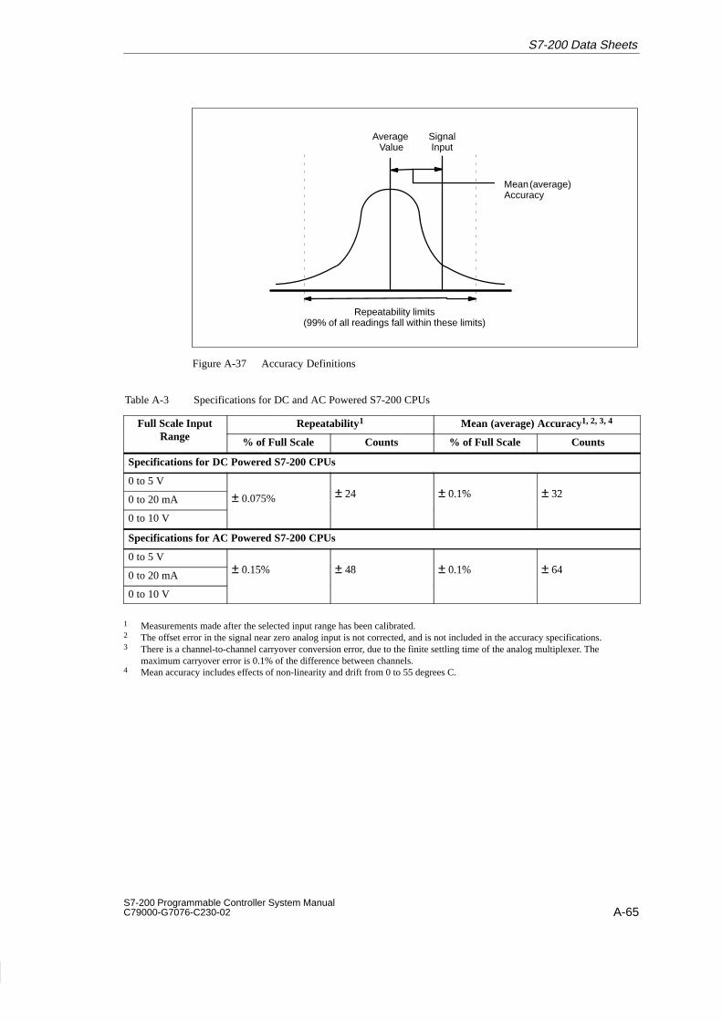
A-65S7-200 Programmable Controller System Manual C79000-G7076-C230-02
Repeatability limits(99% of all readings fall within these limits)
Average Value
Mean (average)Accuracy
SignalInput
Figure A-37 Accuracy Definitions
Table A-3 Specifications for DC and AC Powered S7-200 CPUs
Full Scale InputRange
Repeatability1 Mean (average) Accuracy1, 2, 3, 4
Range % of Full Scale Counts % of Full Scale Counts
Specifications for DC Powered S7-200 CPUs
0 to 5 V± 24 ± 0 1% ± 320 to 20 mA ± 0.075% ± 24 ± 0.1% ± 32
0 to 10 V
Specifications for AC Powered S7-200 CPUs
0 to 5 V± 0 15% ± 48 ± 0 1% ± 640 to 20 mA ± 0.15% ± 48 ± 0.1% ± 64
0 to 10 V
1 Measurements made after the selected input range has been calibrated.2 The offset error in the signal near zero analog input is not corrected, and is not included in the accuracy specifications.3 There is a channel-to-channel carryover conversion error, due to the finite settling time of the analog multiplexer. The
maximum carryover error is 0.1% of the difference between channels.4 Mean accuracy includes effects of non-linearity and drift from 0 to 55 degrees C.
S7-200 Data Sheets

A-66S7-200 Programmable Controller System Manual
C79000-G7076-C230-02
A.34 Expansion Module EM232 Analog Output AQ 2 x 12 Bits
Order Number: 6ES7 232-0HB00-0XA0
General Features
Physical size (L x W x D) 90 x 80 x 62 mm (3.54 x 3.15 x 2.44 in.)
Weight 0.2 kg (0.4 lbs.)
Power dissipation 2 W
Points1 2 analog outputs
Standards compliance UL 508 CSA C22.2 142FM Class I, Division 2VDE 0160 compliantCE compliant
Output Points
Signal rangeVoltage outputCurrent output
± 10 V0 to 20 mA
Resolution, full-rangeVoltage Current
12 bits11 bits
Resolution, full-scaleVoltage, bipolar
Current, unipolar
1 in 2000 counts, 0.5% offull-scale per count1 in 2000 counts, 0.5% offull-scale per count
Data word formatFull-range
Voltage, bipolarCurrent, unipolar
Full-scaleBipolarUnipolar
-32768 to + 327520 to +32752
-32000 to +320000 to + 32000
AccuracyWorst case, 0 to 55° C
Voltage outputCurrent output
Typical, 25° CVoltage outputCurrent output
± 2% of full-scale± 2% of full-scale
± 0.5% of full-scale± 0.5% of full-scale
Settling timeVoltage outputCurrent output
100 µs2 ms
Maximum drive @ 24 V user supply
Voltage outputCurrent output
5000Ω minimum500Ω maximum
Current Requirements
5 VDC logic current 70 mA from Base Unit
External power supply 60 mA, plus output currentof 40 mA from Base Unit orExternal Supply(24 VDC nominal, Class 2 orDC Sensor Supply)
Indicator LED, EXTF
Power supply fault Low voltage, out-of-range
1 The CPU reserves 2 analog output points for this module.
S7-200 Data Sheets

A-67S7-200 Programmable Controller System Manual C79000-G7076-C230-02
Figure A-38 shows the Connector Terminal Identification for EM232 Analog Output AQ 2 x 12Bits.
V0 I0 M V1 I1ANALOG
OUTPUT-PS L+ MM
EM232AQ 2 x 12 Bit
EXTF
+
-
24V
VLoad ILoad
Figure A-38 Connector Terminal Identification for Expansion Module EM232 Analog Output AQ 2 x 12 Bits
Output Data Word Format
Figure A-39 shows where the 12-bit data value is placed within the analog output word of theCPU.
15 4MSB LSB
0AQW XX
0
0 0 0
314
Data value 11 Bits
Current output data format
15 3MSB LSB
AQW XX
0
0 0 0Data value 12 Bits
Voltage output data format
4
0
0 Bipolar(voltage mode)
Bipolar(current mode)
Figure A-39 Output Data Word Format
NoteThe 12 bits of the digital-to-analog converter (DAC) readings are left-justified in the outputdata word format. The MSB is the sign bit: zero indicates a positive data word value. Thefour trailing zeros are truncated before being loaded into the DAC registers. These bitshave no effect on the output signal value.
S7-200 Data Sheets

A-68S7-200 Programmable Controller System Manual
C79000-G7076-C230-02
Output Block Diagram
Figure A-40 shows the EM232 output block diagram.
DATA11 0
VrefD/A converter
Digital-to-analog converter
+
-
R
R
Vout
-10.. +10 Volts
M
Voltage output buffer
+/- 2V
+
-
R
M
+
-
R
Iout
0..20 mA
100
+24 Volt
Voltage-to-current converter
1/4
Figure A-40 EM232 Output Block Diagram
Installation Guidelines for EM232
Use the following guidelines to ensure accuracy:
Ensure that the 24-VDC Sensor Supply is free of noise and is stable.
Use the shortest possible sensor wires.
Use shielded twisted pair wiring for sensor wires.
Terminate the shield at the sensor location only.
Avoid bending the wires into sharp angles.
Use wireways for wire routing.
Avoid placing signal wires parallel to high-energy wires. If the two wires must meet, crossthem at right angles.
Definitions of the Analog Specifications
Accuracy: deviation from the expected value on a given point.
Resolution: the effect of an LSB change reflected on the output.
S7-200 Data Sheets

A-69S7-200 Programmable Controller System Manual C79000-G7076-C230-02
A.35 Expansion Module EM235 Analog Combination AI 3/AQ 1 x 12 Bits
Order Number: 6ES7 235-0KD00-0XA0
General Features
Physical size (L x W x D) 90 x 80 x 62 mm (3.54 x 3.15 x 2.44 in.)
Weight 0.2 kg (0.4 lbs.)
Power dissipation 2 W
Points1 3 analog inputs1 analog output
Standards compliance UL 508 CSA C22.2 142FM Class I, Division 2VDE 0160 compliantCE compliant
Output Points
Signal rangeVoltage outputCurrent output
± 10 V0 to 20 mA
Resolution, full-rangeVoltage Current
12 bits11 bits
Data word format2
Bipolar range3
Unipolar range2-32000 to +320000 to + 32000
AccuracyWorst case, 0 to 60° c
Voltage outputCurrent output
Typical, 25° cVoltage outputCurrent output
± 2% of full-scale± 2% of full-scale
± 0.5% of full-scale± 0.5% of full-scale
Settling timeVoltage outputCurrent output
100 µs2 ms
Maximum drive @ 24 V user supply
Voltage outputCurrent output
5000Ω minimum500Ω maximum
Input Points
Input type Differential
Input impedance 10 MΩ
Input filter attenuation -3db @ 3.1 kHz
Maximum input voltage 30 V
Maximum input current 32 mA
Resolution 12 bit A/D converter
Isolation Non-isolated
Analog-to-digital conversion time < 250 µsec
Analog step response 1.5 ms to 95%
Common mode voltage Signal voltage plus commonmode voltage, less than orequal to 12 V
Common mode rejection 40 dB, DC to 60 Hz
Data word format2
Bipolar range3
Unipolar range2-32000 to +320000 to + 32000
Current Requirements
5 VDC logic current 70 mA from Base Unit
External power supply 60 mA, plus output currentof 20 mA, from Base Unitor External Supply(24 VDC nominal, Class 2 orDC Sensor Supply)
Indicator LED, EXTF
Power supply fault Low voltage, on external 24 VDC
1 The CPU reserves 4 analog input points and 2 analog output points for this module.2 Data word increments in 16 count steps, left justified ADC values. See Figure A-43 and Figure A-45.3 Data word increments in 8 count steps, left justified ADC values. See Figure A-43.
S7-200 Data Sheets

A-70S7-200 Programmable Controller System Manual
C79000-G7076-C230-02
RA A+ A – RB B+ANALOG
IN -OUT-PS L+ MB – RC C+ C – Vo Io
EM235AI 3 x 12 Bit
AQ 1 x 12 Bit
EXTF
Voltage transmitter
Current transmitter
Unusedinput+ -
+
-
V load
I load
24V
Figure A-41 Connector Terminal Identification for Expansion Module EM235 Analog Combination AI 3/AQ 1 x 12 Bits
Calibration and Configuration Location
The calibration potentiometers and configuration DIP switches are accessed through theventilation slots of the module, as shown in Figure A-42.
Expansion module
Offset Gain
OFFON
1 2 3 4 5 6 7 8 9 10 11
Figure A-42 Calibration Potentiometers and Configuration DIP Switches
S7-200 Data Sheets

A-71S7-200 Programmable Controller System Manual C79000-G7076-C230-02
Configuration
Table A-4 shows how to configure the module using the configuration DIP switches.Switches 1, 3, 5, 7, 9, and 11 select the analog input range and data format. All inputs are setto the same input range and format.
Table A-4 Configuration Switch Table for EM235 Analog Combination
Configuration SwitchFull -Scale Input Resolution
11 3 5 7 9 11Full -Scale Input Resolution
ON ON OFF ON OFF OFF 0 to 50 mV 12.5 V
ON ON OFF OFF ON OFF 0 to 100 mV 25 V
ON OFF ON ON OFF OFF 0 to 500 mV 125 V
ON OFF ON OFF ON OFF 0 to 1 V 250 V
ON OFF OFF ON OFF OFF 0 to 5 V 1.25 mV
ON OFF OFF ON OFF OFF 0 to 20 mA2 5 A
ON OFF OFF OFF ON OFF 0 to 10 V 2.5 mV
OFF ON OFF ON OFF OFF +25 mV 12.5 V
OFF ON OFF OFF ON OFF +50 mV 25 V
OFF ON OFF OFF OFF ON +100 mV 50 V
OFF OFF ON ON OFF OFF +250 mV 125 V
OFF OFF ON OFF ON OFF +500 mV 250 V
OFF OFF ON OFF OFF ON +1 V 500 V
OFF OFF OFF ON OFF OFF +2.5 V 1.25 mV
OFF OFF OFF OFF ON OFF +5 V 2.5 mV
OFF OFF OFF OFF OFF ON +10 V 5 mV
1 Switch 1 selects the input polarity: ON for unipolar and OFF for bipolar. CPU power cyclerequired when switching between unipolar and bipolar data formats. Switches 3, 5, 7, 9 and11 select voltage range.
2 0 to 20 mA measurements were made using the internal 250 current-sense resistor.
S7-200 Data Sheets

A-72S7-200 Programmable Controller System Manual
C79000-G7076-C230-02
Input Calibration
The calibration affects all three input channels, and there may be a difference in the readingsbetween the channels after calibration.
To calibrate the module accurately, you must use a program designed to average the valuesread from the module. Use the Analog Input Filtering wizard provided in STEP 7-Micro/WINto create this program (see Section 5.3). Use 64 or more samples in calculating the averagevalue.
To calibrate the input, use the following steps.
1. Turn off the power to the module. Select the desired input range.
2. Turn on the power to the CPU and module. Allow the module to stabilize for 15 minutes.
3. Using a transmitter, a voltage source, or a current source, apply a zero value signal toone of the input terminals.
4. Read the value reported to the CPU by the appropriate input channel.
5. Adjust the OFFSET potentiometer until the reading is zero, or the desired digital datavalue.
6. Connect a full-scale value signal to one of the input terminals. Read the value reportedto the CPU.
7. Adjust the GAIN potentiometer until the reading is 32000, or the desired digital datavalue.
8. Repeat OFFSET and GAIN calibration as required.
Input Data Word Format
Figure A-43 shows where the 12-bit data value is placed within the analog input word of theCPU.
A variance in repeatability of only ±0.50% of full scale can give a variance of ±160 counts inthe value read from the analog input.
15 3MSB LSB
0AIW XX
0
0 0 0
214
Data value 12 Bits
Unipolar data
15 3MSB LSB
AIW XX
0
0 0 0Data value 12 Bits
Bipolar data
4
0
Figure A-43 Input Data Word Format
NoteThe 12 bits of the analog-to-digital converter (ADC) readings are left-justified in the dataword format. The MSB is the sign bit: zero indicates a positive data word value. In theunipolar format, the three trailing zeros cause the data word to change by a count of eightfor each one-count change in the ADC value. In the bipolar format, the four trailing zeroscause the data word to change by a count of sixteen for each one count change in theADC value.
S7-200 Data Sheets

A-73S7-200 Programmable Controller System Manual C79000-G7076-C230-02
Input Block Diagram
Figure A-44 shows the EM235 input block diagram.
R
RC
CC
A+
RA
A-
Rloop
R
RC
CC
B+
RB
B-
Rloop
R
RC
CC
C+
RC
C-
Rloop
A=0
A=1
A=2
A=3
Buffer
+
- R
R
R
R
R
Input ifferential andcommon-mode filter Input selector
AGND
SW11
SW9
SW7
Attenuation stage
xGAIN
DATADATA011
VrefA/D Converter
BIPOLAR UNIPOLAR
SW1
Analog-to-digital converter
SW3OFFONOFFON
SW5OFFOFFONON
GAINx1x10x100Not Valid
Gain stage
Figure A-44 EM235 Input Block Diagram
S7-200 Data Sheets

A-74S7-200 Programmable Controller System Manual
C79000-G7076-C230-02
Output Data Word Format
Figure A-45 shows where the 12-bit data value is placed within the analog output word of theCPU. Figure A-46 shows the EM235 output block diagram.
15 4MSB LSB
0AQW XX
0
0 0 0
314
Data value 11 Bits
Current output data format
15 3MSB LSB
AQW XX
0
0 0 0Data value 12 Bits
Voltage output data format
4
0
0
Figure A-45 Output Data Word Format
NoteThe 12 bits of the digital-to-analog converter (DAC) readings are left-justified in the outputdata word format. The MSB is the sign bit: zero indicates a positive data word value. Thefour trailing zeros are truncated before being loaded into the DAC registers. These bitshave no effect on the output signal value.
Output Block Diagram
Figure A-46 shows the EM235 output block diagram.
DATA11 0
VrefD/A converter
Digital-to-analog converter
+
-
R
R
Vout
-10.. +10 Volts
M
Voltage output buffer
+/- 2V
+
-
R
M
+
-
R
Iout
0..20 mA
100
+24 Volt
Voltage-to-current converter
1/4
Figure A-46 EM235 Output Block Diagram
S7-200 Data Sheets

A-75S7-200 Programmable Controller System Manual C79000-G7076-C230-02
Installation Guidelines for EM235
Use the following guidelines to ensure good accuracy and repeatability:
Ensure that the 24-VDC Sensor Supply is free of noise and is stable.
Calibrate the module.
Use the shortest possible sensor wires.
Use shielded twisted pair wiring for sensor wires.
Terminate the shield at the Sensor location only.
Short the inputs for any unused channels, as shown in Figure A-41.
Avoid bending the wires into sharp angles.
Use wireways for wire routing.
Avoid placing signal wires parallel to high-energy wires. If the two wires must meet, crossthem at right angles.
Ensure that the input signals are floating, or referenced to the external 24V common ofthe analog module.
NoteThis expansion module is not recommended for use with thermocouples.
S7-200 Data Sheets

A-76S7-200 Programmable Controller System Manual
C79000-G7076-C230-02
Understanding and Using the Analog Inputs: Accuracy and Repeatability
The EM235 combination input/output module is a low-cost, high-speed 12 bit analog inputmodule. The module is capable of converting an analog input to its corresponding digitalvalue in 171 µsec for the CPU 212, and 139 µsec for all other S7-200 CPUs. Conversion ofthe analog signal input is performed each time the analog point is accessed by the userprogram. These times must be added to the basic execution time of the instruction used toaccess the analog input.
The EM235 provides an unprocessed digital value (no linearization or filtering) thatcorresponds to the analog voltage or current presented at the modules input terminals. Sincethe module is a high-speed module, it can follow rapid changes in the analog input signal(including internal and external noise). Reading-to-reading variations caused by noise for aconstant or slowly changing analog input signal can be minimized by averaging a number ofreadings. As the number of readings used in computing the average value increases, acorrespondingly slower response time to changes in the input signal will be observed.
You may use the STEP 7-Micro/WIN Analog Input Filtering wizard to add an averagingroutine to your program. Remember that an average value computed from a large number ofsamples will stabilize the reading while slowing down its response to changes in the inputsignal. For slowly changing analog input signals, a sample size of 64 or greater isrecommended for the averaging routine.
The specifications for repeatability describe the reading-to-reading variations of the modulefor an input signal that is not changing. The repeatability specification defines the limits withinwhich 99% of the readings will fall. The mean accuracy specification describes the averagevalue of the error (the difference between the average value of individual readings and theexact value of the actual analog input signal). The repeatability is described in Figure A-47by the bell curve. This figure shows the 99% repeatability limits, the mean or average valueof the individual readings and the mean accuracy in a graphical form. Table A-5 gives therepeatability specifications and the mean accuracy as they relate to each of the configurableranges.
Repeatability limits(99% of all readings fall within these limits)
Average Value
Mean (average)Accuracy
SignalInput
Figure A-47 Accuracy Definitions
S7-200 Data Sheets

A-77S7-200 Programmable Controller System Manual C79000-G7076-C230-02
Table A-5 Specifications for DC and AC Powered S7-200 CPUs
Full Scale InputRange
Repeatability1 Mean (average) Accuracy1, 2, 3, 4
Range % of Full Scale Counts % of Full Scale Counts
Specifications for DC Powered S7-200 CPUs
0 to 50 mV ± 0.25% ± 80
0 to 100 mV ± 0.2% ± 64
0 to 500 mV
0 to 1 V± 0 075% ± 24 ± 0.05% ± 16
0 to 5 V± 0.075% ± 24 ± 0.05% ± 16
0 to 20 mA
0 to 10 V
± 25 mV ± 0.25% ± 160
± 50 mV ± 0.2% ± 128
± 100 mV ± 0.1% ± 64
± 250 mV
± 500 mV ± 0.075% ± 48 ± 0.05% ± 32± 1 V
± 0.05% ± 32
± 2.5 V
± 5 V
± 10 V
Specifications for AC Powered S7-200 CPUs
0 to 50 mV ± 0.25% ± 80
0 to 100 mV ± 0.2% ± 64
0 to 500 mV
0 to 1 V± 0 15% ± 48 ± 0.05% ± 16
0 to 5 V± 0.15% ± 48 ± 0.05% ± 16
0 to 20 mA
0 to 10 V
± 25 mV ± 0.25% ± 160
± 50 mV ± 0.2% ± 128
± 100 mV ± 0.1% ± 64
± 250 mV
± 500 mV ± 0.15% ± 96 ± 0.05% ± 32± 1 V
± 0.05% ± 32
± 2.5 V
± 5 V
± 10 V
1 Measurements made after the selected input range has been calibrated.2 The offset error in the signal near zero analog input is not corrected, and is not included in the accuracy specifications.3 There is a channel-to-channel carryover conversion error, due to the finite settling time of the analog multiplexer. The
maximum carryover error is 0.1% of the difference between channels.4 Mean accuracy includes effects of non-linearity and drift from 0 to 55 degrees C.
S7-200 Data Sheets

A-78S7-200 Programmable Controller System Manual
C79000-G7076-C230-02
A.36 Memory Cartridge 8K x 8
Order Number: 6ES7 291-8GC00-0XA0
General Features
Physical size (L x W x D) 28 x 10 x 16 mm (1.1 x 0.4 x 0.6 in.)
Weight 3.6 g (0.01 lbs.)
Power dissipation 0.5 mW
Memory type EEPROM
User storage 4096 bytes program + 1024 bytes user data + internal system data
Standards compliance UL 508 CSA C22.2 142FM Class I, Division 2VDE 0160 compliantCE compliant
NoteThe 8K memory cartridge is produced in 4-pin and 5-pin versions. These versions areentirely compatible.
This memory cartridge can be used in any S7-200 CPU model, but the 8K memorycartridge will not store the maximum size program that is found in the CPU 215 or theCPU 216. To avoid problems with program size, it is recommended that you use the 8Kmemory cartridge only with the CPU 214 or the PDS 210.
Memory cartridges can only be used to transport programs betwen CPUs of the sameCPU type. (For example, a memory cartridge programmed by a CPU 214 can be used onlyon another CPU 214.)
Memory Cartridge Dimensions
28.5 mm(1.12 in.)
16.5 mm(0.65 in.)
11 mm(0.42 in.)
Figure A-48 Memory Cartridge Dimensions - 8K x 8
S7-200 Data Sheets

A-79S7-200 Programmable Controller System Manual C79000-G7076-C230-02
A.37 Memory Cartridge 16K x 8
Order Number: 6ES7 291-8GD00-0XA0
General Features
Physical size (L x W x D) 28 x 10 x 16 mm (1.1 x 0.4 x 0.6 in.)
Weight 3.6 g (0.01 lbs.)
Power dissipation 0.5 mW
Memory type EEPROM
User storage 8192 bytes program + 5120 bytes user data + internal system data
Standards compliance UL 508 CSA C22.2 142FM Class I, Division 2VDE 0160 compliantCE compliant
NoteThe 16K memory cartridge can be used in the PDS 210, the CPU 214, CPU 215, or theCPU 216.
Memory cartridges can only be used to transport programs betwen CPUs of the sameCPU type. (For example, a memory cartridge programmed by a CPU 214 can only be usedon another CPU 214).
Memory Cartridge Dimensions
28.5 mm(1.12 in.)
16.5 mm(0.65 in.)
11 mm(0.42 in.)
Figure A-49 Memory Cartridge Dimensions - 16K x 8
S7-200 Data Sheets

A-80S7-200 Programmable Controller System Manual
C79000-G7076-C230-02
A.38 Battery Cartridge
Order Number: 6ES7 291-8BA00-0XA0
General Features
Physical size (L x W x D) 28 x 10 x 16 mm (1.1 x 0.4 x 0.6 in.)
Weight 3.6 g (0.01 lbs.)
BatterySize (dia. x ht.)TypeShelf lifeTypical lifeReplacement
9.9 x 2.5 mm (0.39 x 0.10 in.)Lithium (< 0.6 grams)10 years200 days continuous usage*3V 30 mA/hr.(Renata CR 1025)1 year interval recommended
Standards compliance UL 508 CSA C22.2 142FM Class I, Division 2VDE 0160 compliantCE compliant
*The battery is operational only after the super capacitor in the CPU has discharged. Power outages that areshorter than the super capacitor’s data retention time will not subtract from the useful battery life.
Battery Cartridge Dimensions
28.5 mm(1.12 in.)
16.5 mm(0.65 in.)
11 mm(0.42 in.)
Figure A-50 Battery Cartridge Dimensions
S7-200 Data Sheets

A-81S7-200 Programmable Controller System Manual C79000-G7076-C230-02
A.39 I/O Expansion Cable
Order Number: 6ES7 290-6BC50-0XA0
General Features
Cable length 0.8 m (32 in.)
Weight 0.2 kg (0.5 lbs.)
Connector type Edge card
Typical Installation of the I/O Expansion Cable
Ground wire
UP
UP
0.8 m (32 in.)
Figure A-51 Typical Installation of an I/O Expansion Cable
CautionIncorrectly installing the I/O expansion cable can damage the equipment.
If you connect the I/O expansion cable incorrectly, the electrical current flowing through thecable can damage the expansion module.
Always orient the expansion cable so that the word “UP” on the connector of the cablefaces the front of the module, as shown in Figure A-51.
S7-200 Data Sheets
!
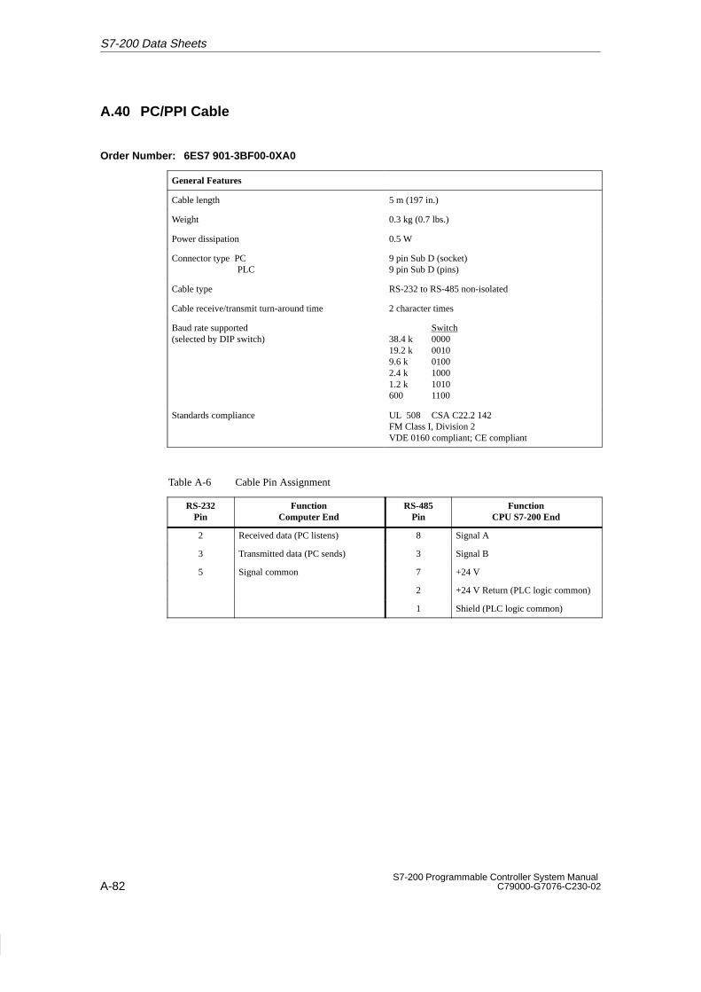
A-82S7-200 Programmable Controller System Manual
C79000-G7076-C230-02
A.40 PC/PPI Cable
Order Number: 6ES7 901-3BF00-0XA0
General Features
Cable length 5 m (197 in.)
Weight 0.3 kg (0.7 lbs.)
Power dissipation 0.5 W
Connector type PC PLC
9 pin Sub D (socket)9 pin Sub D (pins)
Cable type RS-232 to RS-485 non-isolated
Cable receive/transmit turn-around time 2 character times
Baud rate supported(selected by DIP switch)
Switch38.4 k 000019.2 k 00109.6 k 01002.4 k 10001.2 k 1010600 1100
Standards compliance UL 508 CSA C22.2 142FM Class I, Division 2VDE 0160 compliant; CE compliant
Table A-6 Cable Pin Assignment
RS-232Pin
FunctionComputer End
RS-485Pin
FunctionCPU S7-200 End
2 Received data (PC listens) 8 Signal A
3 Transmitted data (PC sends) 3 Signal B
5 Signal common 7 +24 V
2 +24 V Return (PLC logic common)
1 Shield (PLC logic common)
S7-200 Data Sheets

A-83S7-200 Programmable Controller System Manual C79000-G7076-C230-02
CautionInterconnecting equipment with different reference potentials can cause unwanted currentsto flow through the interconnecting cable.
These unwanted currents can cause communication errors or can damage equipment.
Be sure all equipment that you are about to connect with a communication cable eithershares a common circuit reference or is isolated to prevent unwanted current flows. See“Grounding and Circuit Referencing Guidelines for Using Isolated Circuits” in Section 2.3.
PC/PPI Cable Dimensions
0.1 m(4 in.)
0.3 m(12 in.)
RS-232 COMM RS-485 COMM
4.6 m(181 in.)
40 mm(1.6 in.)
Figure A-52 PC/PPI Cable Dimensions
S7-200 Data Sheets
!

A-84S7-200 Programmable Controller System Manual
C79000-G7076-C230-02
A.41 CPU 212 DC Input Simulator
Order Number: 6ES7 274-1XF00-0XA0
General Features
Physical size (L x W x D) 61 x 36 x 22 mm (2.4 x 1.4 x 0.85 in.)
Weight 0.02 Kg (0.04 lb.)
Points 8
User Installation
1
0
DC 24VINPUTS
DCSENSORSUPPLY
23 mm(0.9 in.)
1M 0.0 0.1 0.2 0.3 2M 0.4 0.5 M0.6 0.7 L+
Figure A-53 Installation of the CPU 212 DC Input Simulator
S7-200 Data Sheets

A-85S7-200 Programmable Controller System Manual C79000-G7076-C230-02
A.42 CPU 214 DC Input Simulator
Order Number: 6ES7 274-1XH00-0XA0
General Features
Physical size (L x W x D) 91 x 36 x 22 mm (3.6 x 1.4 x 0.85 in.)
Weight 0.03 Kg (0.06 lb.)
Points 14
User Installation
23 mm(0.9 in.) 1
0
DC 24VINPUTS
0.0 0.1 0.2 0.3 0.4 0.5 M0.6 0.7 L+ DCSENSORSUPPLY
2M 1.0 1.1 1.2 1.3 1.4 1.51M
Figure A-54 Installation of the CPU 214 DC Input Simulator
S7-200 Data Sheets

A-86S7-200 Programmable Controller System Manual
C79000-G7076-C230-02
A.43 CPU 215/216 DC Input Simulator
Order Number: 6ES7 274-1XK00-0XA0
General Features
Physical size (L x W x D) 147 x 36 x 25 mm (3.6 x 1.4 x 0.85 in.)
Weight 0.04 Kg (0.08 lb.)
Points 24
User Installation
L+1.4
1
0
DC 24VINPUTS
0.0 0.1 0.2 0.3 0.4 0.5 M0.6 0.7 DC 24V1.0 1.1 1.2 1.3 2M 1.51M
23 mm(0.9 in.)
0 1
1.6 1.7 2.0 2.1 2.2 2.3 2.4 2.5 2.6 2.7
Figure A-55 Installation of the CPU 215/216 DC Input Simulator
S7-200 Data Sheets