Embed Size (px)
Citation preview
S478-95 Guideline on Durability in Buildings Structures (Design)
'* General Instruction No. 1 S478-95 December 1 995
CSA Standard 5478-95, Guideline on Durability in Buildings, consists of 101 pages (viii preliminary and 93 text), each dated December 1995.
This Standard, like all CSA Standards, is subject to periodic review, and amendments in the form of replacement pages may be issued from time to time; such pages will be mailed automatically to those purchasers who complete and return the attached card.* Some Standards require frequent revision between editions, whereas others require none a t all. It is planned to issue new editions of the Standard, regardless of the amount of revision, a t intervals not greater than 5 years. Except in unusual circumstances, replacement pages will not be issued during the last year of that edition. *This card will appear with General Instruction No. I only.
Although any replacement pages that have been issued will be sold with the Standard, it is for the purchaser to insert them where they apply. The responsibility for ensuring that his or her copy is complete rests with the holder of the Standard, who should, for the sake of reference, retain those pages which have been replaced. Note: A General Instruction sheet will accompany replacement pages each time they are issued and will list the latest dote of each page of the Standard.
Cut along dotted line .......................................................................................... I I
ISSN 03 77-5669 Published in December 7 995 by Canadian Standards Association 7 78 Rexdale Boulevard Etobicoke, Ontario, Canada M9W 7R3
Guideline on Durability in Buildings
9 Contents
Technical Committee on Designing for Durability v
Preface vii
Foreword viii
1. Scope 7
2. Definitions 7
3. Reference Publications 2 3.1 Referenced Standards 2 3.2 Bibliography 3
4. Basic Durability Requirement 3
5. Quality Assurance 3 5.1 Durability and Quality Assurance Through the Building Life Cycle 3 5.2 Elements of Quality Assurance 3 5.3 Elements of Quality Management 4 5.3.1 Program 4 5.3.2 Documentation 4
6. Design Service Life of Buildings and Components 5 @ 6.1 Buildings and Components 5
6.2 Buildings 5 6.3 Components 6 6.3.1 Determination of Component Design Service Life 6 6.3.2 Difficulty and Expense of Maintenance 6 6.3.3 Consequences of Failure 6 6.3.4 Component Selection Related to Technical or Functional Obsolescence and Other Requirements 6 6.3.5 Component Service Life Related to Building Service Life 6 6.4 Specification of Design Service Life 7
7. Predicted Service Life of Components and Assemblies 8 7.1 General 8 7.2 Methods to Predict Service Life 8 7.3 Demonstrated Effectiveness 9 7.4 Modelling of the Deterioration Processes 9 7.5 Testing 9 7.6 Application of Building Science Principles to Modelling of the Deterioration Process 70 7.6.1 Local Environments 7 0 7.6.2 Movement 7 0 7.6.3 Deterioration and Damage Mechanisms 10 7.6.4 Failure 70
8. Design Considerations 7 7 8.1 General 11 8.2 Convention and Innovation 7 7 8.3 Materials Selection 7 7 8.4 Detailing 7 7
December 1995
8.5 Ease of Construction 7 7 8.6 Operation and Maintenance 7 7 8.7 Functional Obsolescence 12 8.8 Life Cycle Cost 72 9. Construction Considerations 72 9.1 Timing 72 9.2 Coordination 72 9.2.1 Bid Document Review 72 9.2.2 Quality control 72 9.2.3 Interaction Among Trades 72 9.2.4 Protection During Construction 73
10. Operation, Maintenance, and lnspection Programs 73 10.1 Operation 73 1 0.2 Maintenance and Inspections 7 3 10.3 Specification of Maintenence and lnspection Programs 73 1 0.4 Implementation 7 4 10.5 lnspection to Verify Maintenance 74 10.6 Timing 74
11. Investigation of Deterioration 7 4 1 1.1 lnvestigation 14 11.1.1 Purpose 74 1 1.1.2 Use of Routine Records of lnspection 74 11.1.3 Monitoring 74 1 1.1.4 Testing 7 4 11.2 Assessment of Deterioration 74 1 1.3 Recommendations for Actions 7 6
12. Repair Work 7 6
13. Renovation 76 13.1 General 76 13.2 Assessment of the Existing Building 76 1 3.3 Environmental Changes 7 7
Appendices A - How to Use the Guideline 78 B - Costs of Premature Deterioration in Buildings 49 C -Assessment of Environmental Conditions 50 D - Deterioration Mechanisms for Building Materials and Their Control 65 E - The Corrosion of Metals in Building Environments 73 F - The Building Envelope 8 7 C - Bibliography 85
December 7 995
Guideline on Durability in Buildings
Technical Committee on Designing for Durability
R.L. Booth*
W.A. Dalgliesht
D.E. Allen
E.F.P. Bumett
M.S. Cheung
C.A. Chown
P. Cicuto
G.P. Cody
J.C. Curtin
B.R. Darrah
L. Fomoville
J.R. Fowler
G. Grondin
S. Johnson
E.D. Jones
R.F. Maua
M. Navabi
Robert Booth Consulting, Etobicoke, Ontario
Calgary, Alberta
National Research Council of Canada, Ottawa, Ontario
University of Waterloo, Waterloo, Ontario
Public Works and Government Services Canada, Ottawa, Ontario
National Research Council of Canada, Ottawa, Ontario
E. & M. Precast Limited, Eto bicoke, Ontario
Construction Control Croup, Woodbridge, Ontario
National Defence Headquarters, Ottawa, Ontario
Society of the Plastics Industry of Canada, Mississauga, Ontario
Canada Brick, Streetsville, Ontario
Canadian Prestressed Concrete Institute, Ottawa, Ontario
University of Alberta, Edmonton, Alberta
Marathon Realty Co. Ltd., Toronto, Ontario
Canadian Wood Council, Ottawa, Ontario
Read .Jones Christoffersen Limited, Toronto, Ontario
City of Vaughan, Maple, Ontario
Chair
Chair
Associate
Associate
Associate
December 7 9 95
B.K. Nayyar
M.A. Patamia
R.L. Quirouette
R.S. Reel
J. Snell
G.R. Sturgeon
R.F. Taylor
C. Tham
J.A. Vlooswyk
W.L. Glover
Ministry of Government Services, Toronto, Ontario
Canadian Concrete Masonry Producers Association, Downsview, Ontario
Quirouette Building Specialists, Vanier, Ontario
Ministry of Transportation, Downsview, Ontario
Moriyama and Teshima Architects, Toronto, Ontario
Masonry Council of Canada, Calgary, Alberta
Morrison Hershfield Limited, North York, Ontario
Toronto Transit Commission, Toronto, Ontario
Building Envelope Engineering, Calgary, Alberta
Canadian Standards Association, Etobicoke, Ontario
Associate
Associate
Administrator
* Deceased. Chair from january 1 993 to October 7 994. t Retired; previously with the National Research Council of Canada, Ottawa. Chair from October 7 994 to present.
Acknowledgements Development of this Guideline was initiated at the request of Public Works and Government Services Canada (PWGSC). CSA acknowledges the major funding and background support provided by PWCSC, and funding support provided by the Department of National Defense, for the development of this first edition.
The Technical Committee acknowledges the contribution made by R. L. Booth. Through his drive and leadership until his resignation due to failing health, the draft was developed from a working concept to a near final document. This Guideline is dedicated to his memory.
December 1995 1

Guideline on Durability in Buildings
Preface
This is the first edition of CSA Standard S478, Guideline on Durability of Buildings. This Guideline sets forth for the first time in North America a set of recommendations to assist designers
in creating durable buildings. The Guideline provides a framework within which durability targets may be set and suggests criteria for specifying durability performance of buildings in terms that are commonly used, but that were previously undefined. To do so, the Guideline contains generic advice on the environmental and other design factors that have an impact on the durability of building components and materials. It identifies the need to consider initial and longterm costs, maintenance, and replaceability in the selection of materials and components.
The Guideline makes it clear that service life requirements and design choices which may affect durability should be thoroughly discussed and agreed upon by all concerned, in particular the owner, designer, and constructor. Model documents for recording these decisions are provided in Appendix A. Later Appendices discuss and expand upon issues related to identification and (relative) quantification of environmental loading, deterioration mechanisms, and damage avoidance strategies including the need for appropriate maintenance over the life of the building.
This Guideline was prepared by the CSA Technical Committee on Designing for Durability, operating under the Standards Steering Committee on Structures (Design) and was formally approved by those Committees.
December 7 995
Notes: (1) Use of the singular does not exclude the plural (and vice versa) when the sense allows. (2) Although the intended primary application of this Standard is stated in its Scope, it is important to note that it remains the responsibility of the user of the Standard to judge its suitability for any particular purpose. (3 ) CSA Standards are subject to periodic review, and suggestions for their improvement will be referred to the appropriate committee. (4) All enquiries regarding this Standard, including requests for interpretation, should be addressed to Canadian Standards Association, Standards Development, 7 78 Rexdale Boulevard, Etobicoke, Ontario M9W 7 R3.
Requests for interpretation should (a) define the problem, making reference to the specific clause, and, where appropriate, include an illustrative sketch; (b) provide an explanation of circumstances surrounding the actual field condition; and (c) be phrased where possible to permit a specific "yes" or "no" answer. Interpretations are published in CSA 's periodical Info Update. For subscription details, write to CSA Sales Promotion, l nfo
Update, at the address given above.
December 7 995 vii
Foreword
Premature deterioration of buildings, resulting in costly repairs and disruptions in use, is an increasing problem. The annual costs related to such repairs and disruptions have now reached multimillion dollar levels.
To a limited degree, the issue of durability is addressed in numerous public documents, including the National Building Code (NBC), materials and installation standards, and manuals of good practice. CSA Standard CANICSA-S413-87, Parking Structures (second edition, December 1 994), was the first Canadian building design standard written specifically to help designers achieve durability and avoid premature deterioration.
Consideration of the issue of durability, however, is often implicit rather than explicit, and is generally limited to particular phases in a building's life cycle and with respect to the implications of premature deterioration. The NBC, for example, is limited by its scope to addressing the issue only at the design and construction phases; it is precluded from addressing maintenance and repair or other factors that can limit deterioration after hand-over to the client. Furthermore, the Code is limited to addressing deterioration affecting the health and safety of building users. It does not address related costs and disruptions to building use.
This Guideline addresses the durability and premature deterioration issues throughout the life of the building, including the necessary maintenance procedures which should be anticipated. It expands, for new buildings, upon concepts relating service life expectations of owners, initial quality, and the impact of regular maintenance programs introduced in the 1993 CSA Standard 5448.1, Repair of Reinforced Concrete in Buildings.
Explicit in this Guideline are the notions that (a) the achievement of durability requires that life expectancy be considered in the design procedures for buildings and their components; f (b) the decisions taken during the life of a building, and even before the development of actual design documents, affect all subsequent decisions and resultant performance; and (c) beginning with the initial concept for a building, the design process should take into account the environmental loads and deleterious agents to which the building components will be exposed.
When new types of materials are introduced into buildings or when traditional materials are used in new applications, these factors are even more important.
This Guideline was developed as an aid to owners and designers. The information contained is neither new nor revolutionary. It is an attempt to put together in one document a realistic method to define and design durable buildings, and to provide guidance on factors to be considered and where answers may be found. Appendices have been provided to supplement, qualify, or expand upon various topics in the Guideline.
The Guideline is a first attempt at such a document, and users are encouraged and requested to submit any and all suggestions for improving and enhancing the information covered. A Proposal for Change form for this purpose is found inside the back cover.
December 7 995
Cuideline on Durability in Buildings
@ S478-95 Guideline on Durability in Buildings
1. Scope 1.1 This Guideline considers the agents and mechanisms related to durability and provides advice for incorporating requirements for durability into the design, operation, and maintenance provisions for buildings and their components.
1.2 The Guideline includes (a) definitions of performance, failure, service life, and other concepts related to building durability; and (b) guidance for designers, builders, owners, and operators on achieving durability by planning the design, construction, maintenance, repair, and renovation of buildings.
1.3 The durability of mechanical and electrical systems and services in buildings is not within the scope of this Guideline. Notes: (1) While not addressed specifically, it is recognized that durability of these systems and services should be included in an integrated design. The principles set forth herein may be considered for application to a building's systems and services provided the effects of internal loads resulting fiom their operation are also taken into appropriate account. (2) The loads on components and the building that result from the operation of the systems and services should be considered along with environmental and structural loads.
2. Definitions Agent -whatever acts on a building or its components that affects service life (eg, water, temperature).
Assembly - an arrangement of more than one material or component to serve specific overall purposes. Examples of assemblies include the total building envelope or individual walls, roofs, or parapets.
Building science - in the design of buildings and their assemblies, the study and application of principles governing physical, chemical, and electro-chemical behaviour in order to predict effects on an assembly due to loads placed on materials and components on and within the assembly, and their impact over time,
Component - any building unit. They may be manufactured, prefabricated, or built or formed onsite, and may be basic units such as nails, cladding anchors, reinforcing bars, and membranes or may be complex units such as cast reinforced concrete slabs or window and door units. A complex component such as a window unit can also be considered as an assembly, depending upon the context.
Defect - a deficiency in a building element that is critical to the performance of the element, eg, a gap in a barrier.
Design service life - the service life specified by the designer in accordance with the expectations (or requirements) of the owners of the building. For given materials and constructions exposed to identical loads, the design service lives for similar buildings are adjusted depending on the amount and nature of maintenance that the owners commit to carry out during the lives of the completed buildings.
December 7 995
Durability - the ability of a building or any of its components to perform its required functions in its service environment over a period of time without unforeseen cost for maintenance or repair.
Envelope - an environmental separator, generally between the inside and outside of a building (including the ground), but also between dissimilar environments within the building.
Environment - all conditions adjoining or permeating a building or any of its elements.
Failure -the loss of performance, as defined by the onset of any of the following limit states: (a) collapse, as related to human safety or to loss of function of the building; (b) local damage, as related to loss of function of the building component or to appearance; (c) displacement, as related to loss of function of the building component or to appearance; or (d) discolouration, as related to appearance of components having an aesthetic function.
Maintenance -the actions and measures taken periodically to maintain a desired level of performance. Maintenance includes a planned program of cleaning, repair, or replacement of identified components such as paint or gaskets.
Performance - the behaviour of a building or any of its components as'related to use.
Predicted service life - the service life forecast from recorded performance, previous experience, tests, or modelling.
Premature failure - failure occurring prior to achievement of the design service life.
Quality - the totality of features and characteristics of products or services that bear on their ability to meet specified requirements.
Quality assurance - all those planned and systematic actions needed to confirm that products or services will sa t i s j l specified requirements.
Quality management - the administrative system established to ensure that required quality assurance procedures have been followed and to direct appropriate corrective action(s) when the specified quality has not been achieved.
Renovation - a program of restoration or modernization of a building to satisfy current building code and functional requirements, with or without a change in use or occupancy of the building, and with or without structural changes.
Repair - action taken, including replacement, to bring the level of performance to a level acceptable to the designer and the owner. It may be part of the planned maintenance program for a building (eg, patching and painting of walls in access corridors) or may be initiated to remedy unexpected damage (eg, repair of a parking slab resulting from premature failure of part of a protective membrane).
Service life -the actual period of time during which the building or any of its components performs without unforeseen costs or disruption for maintenance and repair.
3. Reference Publications 3.1 Referenced Standards This Guideline makes reference to the following Standards:
CSA Standards S413-94, Parking Structures;
S448.1-93, Repair of Reinforced Concrete in Buildings.
December 7 9 95
Guideline on Durability in Buildings
y r ) I S 0 Standard IS0 9001 -94, Quality Systems Model for Quality Assurance in Design/Development, Production, Installation and Servicing.
3.2 Bibliography Appendix C is a bibliography of publications providing guidance and background information on durability in buildings and construction materials. It includes publications identified in the earlier Appendices to this Guideline.
4. Basic Durability Requirement 4.1 Buildings and their components shall be conceived, designed, constructed, and operated and maintained in such a way that, under foreseeable environmental conditions, they maintain their required performance during their design service lives. The predicted service life of buildings and building components and assemblies should meet or exceed
their design service life.
4.2 In the event of renovation, the design service life of the revised structure shall be reconsidered.
4.3 In the event of repairs necessary to correct damage or premature deterioration, the repairs shall be designed, constructed, and maintained to provide the required performance over the design service life agreed upon between the owner and the designer.
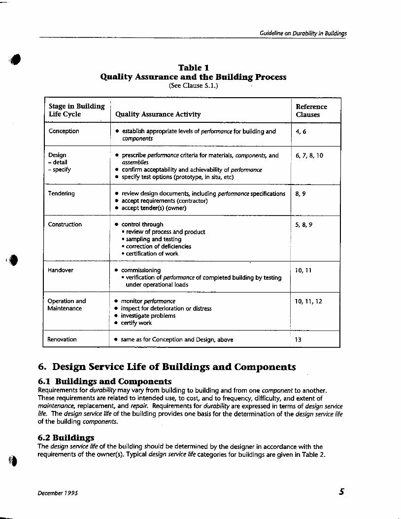
5. Quality Assurance 5.1 Durability and Quality Assurance Through the Building Life Cycle To achieve durability, quality assurance is essential a t every stage in the life of the building. Table 1 identifies the various stages in the life cycle and the specific quality assurance activities that should be completed a t each stage.
5.2 Elements of Quality Assurance
5.2.1 Durability can be achieved only if (a) the required quality of design is provided; (b) the required quality of materials is used throughout; (c) the required quality of workmanship is provided in the construction and maintenance of the building, its components, and assemblies; and (d) the building is operated within the limits for which it was designed.
5.2.2 A fundamental principle of quality assurance is that all persons accept responsibility for the standard of their own work. In order to avoid durability problems, adequate and coordinated quality control obligations should be imposed upon all persons involved and during all phases in the process of defining, planning, building, and operating and maintaining the structure until the end of its service life.
December 7 995
5.2.3 The quality assurance plan of a building should be consistent with its design service life category (see Table 2)) its complexity, and the aggressiveness of environments and agents to which it will be exposed.
5.2.4 Quality assurance requires the coordinated management of expertise, quality control activities, and communications between individuals responsible for different aspects in the overall quality assurance process, and implementation of corrective action when necessary. For this purpose, establishment of a quality management program in conformance with I S 0 Standard I S 0 9001 is recommended.
5.3 Elements of Quality Management I 5.3.1 Program A comprehensive quality management program should be created and im'plemented a t the initiation of every construction project. Its objective should be to verify that necessary quality assurance checks are made, and corrections are promptly made when specified quality is not provided, so that the building and all its components can meet expectations for their performance over their design service lives.
5.3.2 Documentation Communication of performance objectives, expectations, and decisions between owners, designers, and others involved in the different stages of the building process is critical to quality assurance. The development, a t the design stage, of a rational plan for the maintenance of building components, including planned repairs and replacements, will assist in defining the objectives for the designer and expectations of owners and operators (see Clauses 10 and 11). As an aid to this process, design life and maintenance data sheets are provided in Appendix A. It is recommended that these sheets or similar documentation be completed and updated as the design evolves. This documentation should reflect the objectives and expectations agreed to between the designer and the client, and should be provided on
8 completion to the building operators who should maintain and update the information as necessary during the operation and future modifications of the building.
December 7 995
Guideline on Durability in Buildings
Table 1 Quality Assurance and the Building Process
(See Clause 5.1.)
6. Design Service Life of Buildings and Components
Stage in Building Life Cycle
Conception
Design - detail - specify
Tendering
Construction
Handover
Operation and Maintenance
Renovation
6.1 Buildings and Components Requirements for durability may vary from building to building and from one component to another. These requirements are related to intended use, to cost, and to frequency, difficulty, and extent of maintenance, replacement, and repair. Requirements for durability are expressed in terms of design service life. The design service life of the building provides one basis for the determination of the design service life of the building components.
6.2 Buildings The design service life of the building should be determined by the designer in accordance with the
@b requirements of the owner@). Typical design service life categories for buildings are given in Table 2.
Quality Assurance Activity
establish appropriate levels of performance for building and components
prescribe performance criteria for materials, components, and assemblies confirm acceptability and achievability of performance specify test options (prototype, in situ, etc)
review design documents, including performance specifications accept requirements (contractor) accept tender(s) (owner)
control through review of process and product sampling and testing correction of deficiencies certification of work
commissioning verification of performance of completed building by testing under operational loads
monitor performance inspect for deterioration or distress investigate problems certify work
same as for Conception and Design, above
December 7 995
Reference Clauses
4, 6
6, 7, 8, 10
8, 9
5, 8,9
10,ll
10,11,12
13

6.3 Components
6.3.1 Determination of Component Design Service Life The appropriate design service life of each component of a building should be determined considering (a) exposure conditions (see Appendix C); (b) difficulty and expense of maintenance; (c) the consequences of failure of the component in terms of costs of repair, disruption in operation, and hazard to building users (see Table 3); (d) current and future availability of suitable components; (e) the design service life of the building (see Appendix A); and (f) technical or functional obsolescence.
6.3.2 Difficulty and Expense of Maintenance When determining the design service life for building components, it is suggested that a t least three categories (more, for more complex components) be used to describe necessary maintenance : "little or none", "significant", and "extensive". Individual components can then be classified under the appropriate category by considering costs, difficulty, extent, and frequency. The selection or design of components and the specification of the necessary maintenance should be determined by balancing initial costs, operations and maintenance costs, and acceptable levels of effort during maintenance. To extend the lifecycle, selection of components with inherent superior durability, implementation of a more comprehensive maintenance program, or both, should be specified.
6.3.3 Consequences of Failure Table 3 identifies eight categories of failure defined by the worst consequence of a failure in that category. Components whose failure threatens life or health should be designed to provide a greater reliability during the design service life than those whose failure does not threaten life or health. Structural assemblies or members, such as roof trusses over a swimming pool or load-bearing columns supporting a parking structure, are examples of components that would generally require both a longer design service life and greater reliability in provisions specified to ensure their durability. Note: The consequences of failure to maintain an assembly can be illustrated by the following example: a cladding anchor that corrodes prematurely because a sealant has unbonded or cracked may fail, causing injury or property damage. The cause may be lack of maintenance. If a detail is determined to be critical to durability, it may be prudent to design redundant protection, particularly if its cost is negligible and the risk of failure is greatly reduced.
6.3.4 Component Selection Related to Technical or Functional Obsolescence and Other Requirements The design service life of a component or assembly will also depend on the availability of durable components and knowledge of construction methods required for their proper installation. Even when components and assemblies whose predicted service lives approach that of the building are available, other considerations such as aesthetics or environmental impact may preclude their use.
6.3.5 Component Service Life Related to Building Service Life Permanent components of a building (foundations, basement walls, and main structural members) should be expected to perform for the life of the building. Moveable or removable components (partitions in an office building, interior finishes) should be designed to last only as long as they will remain useful. Exterior claddings can normally be expected to provide service lives of 20 or more years. A cladding system requiring little maintenance for temporary buildings may require extensive maintenance if used on "permanent" buildings. A rational plan for maintenance of building components, including repair and replacement, should be set
up as indicated in Clauses 10 and 11 and Appendix A. Note: Ideally, at the end of the service life of a building, each component and assembly in that building would reach the end of its service life and instantaneously biodegrade, leaving a clean site and no material disposal problems. In reality, the service l i ~ e s of components vary widely, depending on their exposure to damaging agents, and will have service lives longer
December 1 995

Guideline on Durability in Buildings
,@ or shorter than the building. The use of components and materials which lend themselves to recycling at the end of their functional lives may be a practicable solution.
6.4 Specification of Design Service Life A statement of the design service life, in years, for both the building and its components and assemblies should be established between the designer and the owner. The design life statement should be accompanied by information on (a) building, component and assembly design service lives; (b) exposure conditions, environments, and limits on use; (c) recommended maintenance, in accordance with Clause 10; (d) design exposure conditions (Clauses 7 and 8). The data sheets found in Appendix A may be modified and used to establish and record the necessary
data for a building. The information necessary to ensure that the design concept and objectives are realistic and achievable
should be communicated to all parties involved in the construction process, including consulting designers, contractors, fabricators and suppliers, and construction trades.
Table 2 Categories of Design Service Life for Buildings
(See Clauses 5.2.3 and 6.2.)
Parking structures should have a design service life at least equal to the building they serve, except parking structures serving long life category buildings may be designed for medium life provided they are not located directly under the long life superstructure or provided deterioration of the parking structure would not adversely affect the building served. See CSA Standard 54 13. t Buildings are not designed as a heritage structures but may be assigned the designation by virtue of their historical significance. One purpose of applying such a designation to a building is to ensure that, henceforth, it will be preserved permanently. The concepts contained in this Guideline will be of assistance in establishing appropriate maintenance and repair programs for designated buildings.
December 7 995
Examples
non-permanent construction buildings, sales offices, bunkhouses temporary exhibition buildings
most industrial buildings . most parking structures*
most residential, commercial, and office buildings health and educational buildings parking structures below buildings designed for long life category*
monumental buildings (eg, national museums, art galleries, archives) heritage? buildings
Category
Temporary
Medium life
Long life
Permanent
Design service life for building
Up to ten years
25 to 49 years
50 to 99 years
Minimum period, 1 00 years
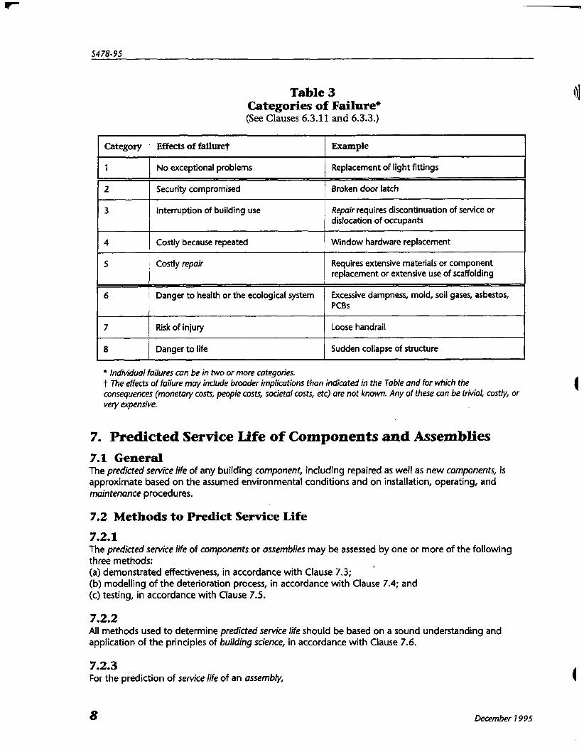
Table 3 Categories of Failure* (See Clauses 6.3.11 and 6.3.3.)
Individual failures can be in two or more categories, t The effects of failure may include broader implications than indicated in the Table and for which the consequences (monetary costs, people costs, societal costs, etc) are not known. Any of these can be trivial, costly, or 4 very expensive.
Category
1
2
3
4
5
6
7
8
7. Predicted Service Life of Components and Assemblies 7.1 General The predicted service life of any building component, including repaired as well as new components, is approximate based on the assumed environmental conditions and on installation, operating, and maintenance procedures.
Effects of failu*
No exceptional problems
Security compromised
Interruption of building use
Costly because repeated
Costly repair
Danger to health or the ecological system
Risk of injury
Danger to life
7.2 Methods to Predict Service Life
Example
Replacement of light fittings
Broken door latch -
Repair requires discontinuation of service or dislocation of occupants
Window hardware replacement
Requires extensive materials or component replacement or extensive use of scaffolding
Excessive dampness, mold, soil gases, asbestos, PCBs
Loose handrail
Sudden collapse of structure
7.2.1 The predicted service life of components or assemblies may be assessed by one or more of the following three methods: (a) demonstrated effectiveness, in accordance with Clause 7.3; (b) modelling of the deterioration process, in accordance with Clause 7.4; and (c) testing, in accordance with Clause 7.5.
7.2.2 All methods used t o determine predicted service life should be based on a sound understanding and application of the principles of building science, in accordance with Clause 7.6.
7.2.3 For the prediction of service life of an assembly,
December 7 995

Guideline on Durability in Buildinqs
yl) (a) demonstrated effectiveness may be applied where identical assemblies have been used (i) successfully; and (ii) in the same environments;
(b) modelling and demonstrated effectiveness should be applied where (i) a similar component or assembly has been used successfully in the same environments; or (ii) proven components or assemblies have been used successfully, but in moderately different
environments; and (c) modelling and testing should be applied where
(i) innovative components and assemblies are to be used; or (ii) proven components or assemblies are to be used in significantly different environments.
The degree to which an assembly or its components are innovative or the service environment is dissimilar to one previously experienced should be established by the application of building science principles.
7.3 Demonstrated Effectiveness
7.3.1 Requirements for durability of specific components are contained, although often not explicitly identified, in current codes, standards (see Appendix D), and other sources (see Appendix C). These requirements usually imply service lives of components which are consistent with current expectations and which may be considered appropriate for buildings of medium or long design service life.
7.3.2 The prediction of service life may also be based on documented records of successful performance and from information on deterioration problems reported in the literature. The latter also is particularly useful for assessing relatively innovative assemblies and for innovative components used in conventional
10 assemblies.
7.4 Modelling of the Deterioration Processes The prediction of service life of any component of an assembly by modelling of the deterioration processes requires consideration of (a) the function(s) of the component (eg, air and/or moisture barrier); (b) the environments adjacent to and within the components; (c) the relative movement of adjacent components or assemblies; (d) the deterioration or damage mechanisms that occur as a consequence of the environment, and interactions with adjacent assemblies; and (e) the limit states (eg, fracture, damage, movements, gaps, discolouration, etc) defining functional failure of the component in the assembly.
7.5 Testing
7.5.1 The purposes of testing are (a) to validate and quantify conclusions from modelling described in Clau~e 7.4; (b) for quality assurance purposes prior to and during construction; and (c) for investigation of existing buildings.
7.5.2 The following types of testing may be carried out: (a) laboratory tests to determine conditions on and within assemblies exposed to controlled simulated environments (eg, rain penetration, air leakage, and temperature differentials) adjacent to the assemblies; (b) durability tests of materials, components, and assemblies to determine their deterioration and failure mechanisms and time to failure under natural or simulated environments; or
December 1995
(c) field tests of constructed assemblies to determine transport and accumulation of agents, either during construction for quality assurance purposes or during the investigation of existing conditions in a building. Note: Simulated environments may represent extreme cases of natural environments or "acce1erated"extreme natural environments, Special care must be taken in extrapolating the results of testing based on naccelerated" methods ro the predicfion of service life.
7.6 Application of Building Science Principles to Modelling of the Deterioration Process
7.6.1 Local Environments Modelling of the deterioration process requires an understanding of the delivery mechanisms and accumulation rates of agents which promote deterioration. These will be based on knowledge about the immediate surroundings of components and their place in specific assemblies. Moisture, with or without contaminants, is the most important environmental agent causing premature
deterioration. The application of principles of building science permits the generation of models for predicting the mechanisms, paths, volumes, and forms of moisture which building assemblies will need to accommodate and resist. Guidance on the assessment of the environment and environmental agents, including moisture,
contaminants, and temperature is contained in Appendices C, Dl and E.
7.6.2 Movement The relative movement of adjacent components is determined from a consideration of dimensional changes of individual components due to material characteristics, temperature, moisture changes in materials and the atmosphere, and stresses due to service loads. The relative movement of adjacent assemblies is determined from a consideration of dimensional
changes of the assemblies due to temperature and moisture changes in materials comprising the assembly, temperature and moisture changes in the atmospheres, differential movements in supporting structures, and stress.
7.6.3 Deterioration and Damage Mechanisms Deterioration and damage mechanisms are consequences of the expected environmental conditions, the chemical and physical properties of the materials of the components, and the interaction of the different components, including chemical (eg, galvanic corrosion) and physical (eg, movements, deformations) interactions. Corrosion is currently a very costly unforeseen durability problem in buildings. It is only partially
addressed by current building codes and standards. An introduction to corrosion is provided in Appendix E. Guidance on the identification of deterioration or damage mechanisms and their control is provided in
Appendix D for materials and in Appendix F for building envelope assemblies.
7.6.4 Failure Failure is defined not by the occurrence of deterioration or damage mechanisms but by their effects. The effects depend on the functions of the component (eg, moisture barrier, drainage component) or on its visual appearance. A deterioration mechanism occurring on or inside an assembly does not necessarily mean failure. Therefore it is important to consider not only component environments and deterioration and damage mechanisms, but which limit states (eg, fracture, movements, gaps, appearance, material weakening) correspond to functional failure in the intended use. Some guidance is given in Appendix D on the forms of failure associated with prevalent deterioration mechanisms for materials and in Appendix F for building envelope assemblies.
December 7 995

Guideline on Durability in Buildings
, 8. Design Considerations 8.1 General Designers in particular should be aware of the issues related to durability. The design considerations identified herein should be of assistance in developing a strategy to assure durability generally. Appendix F contains additional information on the design aspects of the building envelope.
8.2 Convention and Innovation Designs should be based on existing Standards and proven design and construction practices wherever possible. This recommendation and Clauses 8.3 to 8.7 should not be interpreted as discouraging the use of new materials or approaches to the design or construction of buildings and their components. However, the use of innovative technology should be based on sufficient modelling or testing (see Clause 7) to ensure the likelihood of a high level of success in the application.
8.3 Materials Selection Materials should (a) have compatible physical and chemical properties when in contact or close association; (b) have physical and chemical properties appropriate for the environment; and (b) have physical properties compatible with anticipated differential movements.
8.4 Detailing Detailing should be provided using clear, concise, and complete drawings and specifications, and should, where necessary, (a) provide barriers and seals to resist the infiltration or deposition of moisture or other deleterious agents; (b) provide airseals, drainage, and venting between and through assemblies to minimize the
@ accumulation of moisture or other deleterious agents; (c) minimize the risk of local concentrations of moisture and deleterious materials through appropriate geometry, form, and placement of components; and (d) minimize exposure of components to environmental loads.
8.5 Ease of Construction The design concept for a building and its components must be buildable to achieve the necessary level of quality. Ease of construction may be improved when design documents (a) incorporate the input of contractors, fabricators, and suppliers knowledgable in the use and installation of materials and systems to be specified, and of the staff who will be responsible for the operation of the completed building; (b) use normally available and commonly used durable materials; (c) specify a realistic and achievable level of workmanship; (d) use standard approaches to, and methods of, construction; (e) use simple construction techniques; (f) consider sequence of construction; (g) incorporate flexibility to allow response to changes in design, construction, scheduling, conditions, or materials availability that may arise during construction; (h) recognize the allowable and expected construction tolerances of the components being designed and of adjacent building elements (which may exceed those of the component); and (i) minimize the frequency and extent of interfacing between work by different trades.
Components and techniques which are critical or difficult to install correctly should be clearly detailed and explained in design documents.
8.6 Operation and Maintenance iQ Designs for buildings, their components, and assemblies should
December 1 995

(a) allow for ease of access for inspections, testing, maintenance, repair, and replacement of components and assemblies, including mechanical and electrical systems and services, during the construction phase and throughout the service life of the building, its components, and its assemblies; (b) identify building components, including mechanical and electrical systems and services, that require special care through the construction and operation and maintenance phases.
8.7 Functional Obsolescence Designs for buildings expected to undergo changes in usage and tenancies over the service life of the building should make appropriate allowance for future alterations of the contained spaces, probability of obsolescence of installed services, and the desirability of recycling or reusing components.
8.8 Life Cycle Cost All decisions pertaining to materials selection, detailing, buildability, and operation and maintenance should take into consideration not only the first costs but all life cycle costs.
9. Construction Considerations 9.1 Timing Construction contractors, their suppliers, and the building operators should be involved in the design/construction process as early as possible, to achieve better understanding of the intended functions of the building and its components, and for better coordination of the construction methods and their sequence.
9.2 Coordination
9.2.1 Bid Document Review Prior to tender, those involved in tendering sRould review in detail all design documents. The designers should communicate to the contractors and suppliers the intended functions of the proposed design and point out aspects critical to the proper performance of the design. Prior to the start of construction, all design documents should again be reviewed in detail by the
successful contractors and suppliers, and the designers should again communicate the intended functions and critical aspects of the final design. The contractors and suppliers should confirm that they have a clear understanding of the proposed building and component functions, specified materials, and the proposed methods for fabrication of components and construction of the-building. Unclear items should be resolved with the designers before construction begins. The use of partial construction or mock-ups of critical building components prior to construction is recommended, particularly where innovative materials, products, or concepts are being introduced.
9.2.2 Quality Control Prior to the start of construction, those involved should establish quality control by adopting appropriate quality management procedures as described in Clause 5. The designer should remind the owner and the contractor to as;ign appropriate resources and
measures to achieve specified construction and installation details and tolerances. There should be on-going and continuous communication between all parties involved in the
construction to ensure that standards are being met and that appropriate corrective actions are selected and implemented if specifications cannot or have not been met.
9.2.3 Interaction Among Trades Prior to the start of construction, those involved should assign scopes of work to appropriate trades, establish coordination between trades, and schedule and phase the work to achieve proper construction
72 December 1 995

Guideline on Durability in Buildings
and installation of all building components and assemblies. The trades should be briefed on any new or unusual construction procedures or design innovations to ensure that they can be built as specified. Suppliers and fabricators should notify the designers, contractors, and installers when special
construction related procedures are required to protect components during construction. Before beginning its work, it is advisable that each trade examine preceding work of other trades to
confirm that conditions appear to provide a satisfactory base to its own work. New work contingent on preceding work should not be executed until preceding work identified as
unsatisfactory is corrected.
9.2.4 Protection During Construction During construction, those involved should provide for the proper and adequate transport, handling, and storage of materials, components, and assemblies, to protect them against damage or deterioration during the construction period. Designers should inform contractors and suppliers of components and assemblies which may require special care and protection prior to installation.
10. Operation, Maintenance, and Inspection Programs Note: Operation, maintenance, and inspection programs described in this Clause are intended for execution by the owner of the building.
10.1 Operation Operating conditions inside a building will have significant long-term impacts on component and assembly durabilities. Buildings should be operated within the design parameters of temperature, relative humidity, and pressure differentials for which the building was designed and fitted. In any event, the variance between operating and design conditions should be controlled within specified tolerances.
Operating procedures used outside of the building should be planned and carried out to avoid excessive exposure of the structure to damaging agents. For example, salt-laden snow should not be piled against exterior walls because the chlorides can increase the rate of deterioration, and high pressure water should not be used for cleaning where there is danger of damaging seals and sealants.
10.2 Maintenance and Inspections The objective of operations and maintenance programs should be to provide a t reasonable cost a clean, reliable, functional, safe, and healthy environment. Programs of routine maintenance and inspection are necessary to ensure that the building and its materials, components, and assemblies perform their required functions for the duration of their design service lives.
10.3 Specification of Maintenence and Inspection Programs
10.3.1 It is recommended that maintenance and inspection programs be prepared during the production of construction documents. This is an important exercise, especially for the owners of the completed building, in that it requires
these issues to be identified and considered prior to construction. Establishment of an appropriate maintenance and inspection budget should be a specific consideration.
As construction proceeds, these programs should be extended and revised to reflect as-constructed needs and results. (See Appendix A and Table A3.)
10.3.2 Though not currently included in the general scope of work in client-architect agreements, a maintenance and inspection database should be obtained by the owner and should include (a) as-built drawings; (b) shop drawings;
December 7 995

(c) Comprehensive Design Life and Maintenance Summary Table (see Appendix A); (d) work methods and operating manuals; (e) training information; (0 recommended schedules of inspection, preventative and corrective maintenance identifying tasks, and required resources (time, personnel, tools, materials, etc); and (g) appropriate forms for recording histories of maintenance and inspections conducted.
10.4 Implementation Once the building is completed and occupied, this comprehensive maintenance and inspection program should be implemented by the owner. Allowance for an adequate budget to do the necessary work will be required.
10.5 Inspection to Verify Maintenance Visual inspections should be conducted at regular intervals to verify that the maintenance is being carried out as required and to identify and document any signs of deterioration a t the earliest possibre stage. Frequency of inspection of a given building component should be specified based on the recommendation of the professional responsible for the design of that component. This recommendation is often based on manufacturer criteria, and depends on the installation and function of the component. Significant changes in the conditions of a material, component, or assembly observed between successive
visual inspections or over a series of inspections generally indicates the need for a more thorough visual inspection with additional data collection, or for a more detailed investigation. The prolonged presence of moisture should generally be a concern. Where a problem is identified during a regular inspection, a professional should be called in (see
Clause 11) to investigate.
10.6 Timing The timing of repairs with respect to the development of the defects is of paramount importance. Early detection of deterioration symptoms and determination and correction of the cause of problems is recommended.
11. Investigation of Deterioration Note: This Clause is intended for implementation by an appropriately qualified professional when the owner has identified symptoms of deterioration that may indicate problems that cannot be corrected by routine maintenance and repair work, or when a general assessment of the health of the building is wanted.
11.1 Investigation
11.1.1 Purpose The proper identification of the agents and mechanisms responsible for the deterioration is essential for the appropriate repair to be devised. An investigation is usually required for an accurate diagnosis and includes (a) recording the extent of the deterioration and the way in which the agent of the defect has manifested itself (the symptoms); (b) collecting and recording of all relevant data; (c) comparing the symptoms and the known behaviour of the materials, components, and assemblies involved; and (d) relating the symptoms to the environment to which the materials, components, and assemblies have been exposed.
All of these require the application of building science principles.
Guideline on Durability in Buildings
@ 11.1.2 Use of Routine Records of Inspection Routine documented visual inspections, recommended to be part of a regular maintenance program, provide the simplest means for identifying deterioration in materials, components, and assemblies.
11.1.3 Monitoring Monitoring of the damaged components through instrumentation and comparison against known benchmarks should be considered where it is not certain from visual inspections whether identified damage can be considered stabilized or can be expected to deteriorate further.
11.1.4 Testing Tests and measurements of conditions, properties, and performance of materials, components, and assemblies, may include (a) moisture determination; (b) chemical analysis; (c) physical analysis; and/or (d) simulation.
11.1.4.1 Non-Destructive Testing Non-destructive test methods, causing little or no disruption of the material, component, or assembly, may provide additional information on the extent of deterioration where visual inspection indicates an area of concern. Accuracy of the tests generally increases with the uniformity of the material. Since the assessment is largely qualitative, the amount and usefulness of the information gained generally increases with the knowledge and judgement of the investigator.
11.1.4.2 Partially Destructive Testing Partially destructive test methods may be preferred over non-destructive methods where greater accuracy or additional information is required. These tests usually involve the removal and destruction on-site of small samples from a representative area of the material, component, or assembly.
11.1.4.3 Off-Site Testing Off-site testing requires sampling, transporting, and testing of representative sections of the material, component, or assembly. It involves quantitative evaluation and usually provides a greater degree of accuracy than non-destructive or partially destructive testing. More properties can be evaluated under controlled laboratory conditions than in the field.
11.1.4.4 In-situ Testing In-situ testing provides a means of evaluating a full scale, undisturbed sample of the material, component, or assembly and provides an in-service measure of performance and conditions under a defined controlled constant or varying environment. The resistance of the component to both structural and environmental loads can be tested and measured. Sacrificing representative sections may be necessary to determine the current condition and extent of deterioration throughout a larger section or assembly.
11.2 Assessment of Deterioration The data obtained through investigation, monitoring, and testing requires assessment by qualified personnel to determine (a) the significance of the deterioration or failure in the context of the performance of the material, component, or assembly and of the building; (b) the cause and source of the deterioration; and (c) the scope and nature of repair work which may be required,
" 0 Note: Frequently more than one contributing factor may be responsible for the particular deterioration or failure being considered, and sources may be interactive.
December 7 995
11.3 Recommendations for Actions Based on the assessment, the investigator should prepare a written report including, when appropriate (a) the assessment of the effects of the damage or deterioration on the safety, serviceability, and intended
1 durability of the building; (b) recommendations for needed repairs or replacement of deteriorated components; (c) recommendations for correction of conditions which caused the deterioration; (c) recommendations for additional protection systems required to achieve the required design service life; and (e) recommendations for maintenance procedures required to achieve the design service life. Note: The design service life in this context is intended to be compatible with that originally scheduled for the component(s) affected, and may extend only until the next planned replacement date. I
12. Repair Work I 12.1 Repair work must be based on as accurate a diagnosis of the cause of the deterioration or failure as is reasonably possible. Unless this is done, the repairwork may prove to be inappropriate or short-lived, or may lead to other deterioration or failures. The scope and nature of repair depends upon
(a) the precise nature of the deterioration or failure and its impact on immediate and long-term use of the building; (b) the design service life for the repair; (c) the cost and disruption to use of the building during the course of the repair work; and (d) funding allocated in the maintenance budget. Note: The general concepts set forth in CSA Standard 5448.7 may be of use in considering the repair of buildings of all materials as well as those of reinforced concrete.
13. Renovation I I
13.1 General Renovation design should take fully into account the uses (and occupancies, in the context of the applicable building code) for which the building was originally designed and uses (occupancies) for which the design is to be altered. The renovated building and its components should be conceived, designed, constructed, and operated
and maintained so as to satisfy the durability guidelines of Clauses 4 to 10.
13.2 Assessment of the Existing Building The current condition of the building should be assessed in terms of its ability to provide acceptable performance to satisfy the uses for which the renovation will be designed. Such assessment must include (a) identification of all architectural and structural changes necessary to meet current codes and standards with respect to
(i) structure; (ii) environmental separators; (iii) serviceability; (iv) mechanical systems; and (v) electrical systems; and
(b) identification of needed repairs.
Guideline on Durability in Buildinrrs
'@ 13.3 Environmental Changes Changes to the indoor environment(s) resulting from changes to the use and occupancy or changes to interior heating, ventilation, and humidification systems should be identified and, so that the expected performance, predicted service life, and operating and maintenance requirements are appropriate for the revised design service life of the renovated building, (a) it should be confirmed that the existing envelope will provide the required separation between the altered interior and exterior environments; or (b) any alterations required to components of the building envelope should be identified and specified; and (c) the maintenance procedures necessary to attain that design service life should be identified and documented for the building operators.
December 7 995

Appendix A How to Use the Guideline
Note: This Appendix is included for information purposes only.
Al . Geheral This Guideline provides a framework within which design considerations related to building life and durability can be organized and addressed. The Guideline assumes that the objective of the designer will be to provide a building which will be durable and functional for a t least the time period required by the owner. Building codes do not currently establish explicit targets for the life of buildings. Table 2 in the
Guideline identifies and defines (in years) categories of design service life for typical building types. The building design service life should be specified by the owner. While the specified design service life establishes the overall objective for the design, it is neither
necessary nor desirable that all components of the building have the same design life. For example, the interior spaces of most commercial office buildings are expected to become functionally obsolescent, perhaps several times during the building's service life. If this will be the case, owners and designers should plan, therefore, for periodic redecoration and internal rearrangement to satisfy the needs of tenants. In this instance it is more cost efficient to set a target life for interior partitions based on the expected time until redecoration. Other factors which have an impact on design service life decisions are identified in the Guideline. The Guideline views the process of designing for durability as following a decision tree model, with the
determination of the final design being an iterative process that begins with the overall concept and culminates in working drawings which will ensure the required durability as well as meeting structural and other building code needs. The Guideline also identifies that the realization of design service life is
1 dependent on the operational practices and maintenance programs enacted by the owner. When conformance to this Guideline is specified, all parties involved in the design, construction, and
ownership of a building are required by Clause 4 to conscientiously carry out their respective responsibilities to ensure a reasonable probability that service life a t least achieves design service life.
A2. Design Information A2.1 General To ensure the intended degree of durability is achieved, decisions related to the design service life of the structure, its components, and assemblies, and to the operational and maintenance constraints acceptable to the owner should be documented and used as the basis for design. The use of Tables A1 tc, A3 is recommended as a means of recording and explaining durability design targets and assumptions for a building and its components and for communicating this information to future owners of the building. The sample documentation tables contained in this Appendix, or other formats providing the same
information, should be completed by the designer during the conceptual stage, and updated as required throughout the design, tendering, and construction process (see Clause 5). Such tables identify clearly the designer's intentions for the design durability of the building and its assemblies. They should advise the client and subsequent owners of
the designer's response to the client's stated needs; the need for maintenance of components of the building; the building's operational parameters and tolerances; and, the frequency and nature of recommended maintenance programs. The sets of documentation tables, described below in more detail, comprise
(a) Table A l , Building Design Data;
December 1 995
Guideline on Durabilitv in Buildinas
,.() (b) Table A2, Preliminary Design and Maintenance Option$ and (c) Table A3, Comprehensive Design and Maintenance Summary. To illustrate the process of documenting decisions, the tables contained in this Appendix are in the form
of completed examples for two typical structures - a highrise office building (Tables A (HRO)) and a lowrise residential condominium building (Tables A (LRR)). In practice, these design documentation tables are to be adapted and expanded as necessary to reflect the actual building and the structural and other systems to be utilized in its construction.
A2.2 Table A1 - Building Design Data Tables A1 (HRO) and A1 (LRR) are completed examples of Building Design Data sheets. Their intended function is to document the basic requirements for the building and the design variables the designer will need to work with, as agreed with the owner. The two aspects of the Building Design Data table that are uniquely necessary to the durability design process are the specification of design service life (see Clause 6.2 and Table 2) and the documentation of environmental variables for the purpose of identifying potentially harmful agents (Clause 7.6 and Appendices C, Dl E, and F). Once completed and accepted by both the designer and owner, the Building Design Data table would
normally not be altered unless there is a major alteration in the owner's requirements for use of the building or the construction system proposed, or unless the attendant operational and maintenance obligations are found to be too onerous or unworkable.
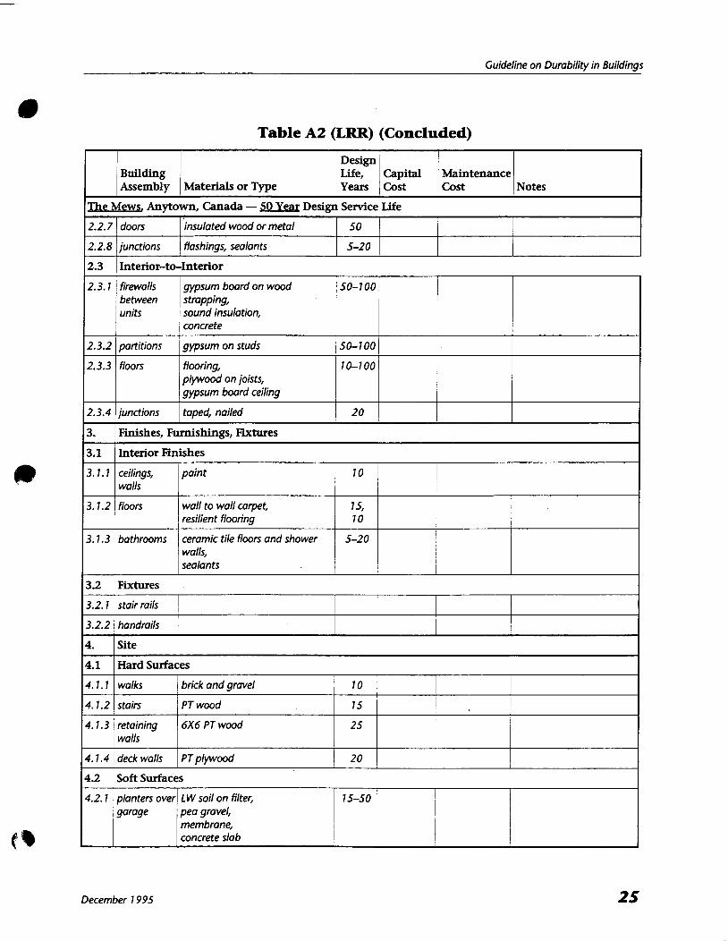
A2.3 Table A2 - Preliminary Design and Maintenance Options Table A2 is intended to record, in summary form, the assemblies and components options to be considered for design of the building documented in Table Al. Table A2 adds detail to the structural and other construction systems initially proposed in Table Al. In addition to describing the assemblies and principal components under consideration, the table
identifies their individual design service life. As noted previously, the service life of non-critical or readily @ replaceable components can be much shorter than that of the building. Clauses 6.3 and 8 and Table 3 in the Guideline provide information on the factors that need to be taken into account when determining (a) the design service life to be met by components or assemblies and (b) the materials and construction methods selected for preliminary design detailing. Initially the "costs" to be identified (capital and maintenance) could be stated either as rough estimates
or, if more than one option is being examined, in relative terms. The consequences of failures on the safety and serviceability of the building should be identified at this stage. As the design becomes more refined, insertion of actual projected capital and maintenance costs may be important in determining final materials, component, and assembly selections. Non-typical environmental separators should be identified and addressed when their environment signals
the needs for particular consideration to ensure protection against premature deterioration. Assemblies enclosing indoor swimming pools, walk-in freezers, chimneys, or manufacturing operations using acids or other caustic chemicals are four examples where special precautions to protect against premature deterioration, or to allow for economical replacement, may need to be taken.
A2.4 Table A3 - Comprehensive Design and Maintenance Summary Table A3, as shown for the two completed examples, provides a detailed summary of the principal components and their recommended maintenance and replacement schedules. This table also includes provision for indicating the nature of maintenance that will need to be done and to indicate any particular problems associated with carrying out the work. Minor components critical to the durability of assemblies or the building, or critical to the safe fun.ctioning of the building (eg, sealants required to control moisture or air leakage, and corrosion resistant structural hangers and connectors) should be identified. Completion of the component maintenance sections of Table A3 will serve to verify or correct the maintenance costs forecast in Table A2. The designer can indicate for each component in Table A3 the level of maintenance necessary to realize
their design service lives. The level and nature of the planned maintenance relate to cost, difficulty, or
December 7 995
frequency of the planned work. A benefit of the A3, Summary tables is that they identify explicitly for the client and subsequent owners the extent of maintenance necessary to ensure that design service lives are achieved. These maintenance activities may range in scope from simple regular inspection, to occasional cleaning, to unscheduled minor or major repairs, to planned component replacements. If Table A3 is reviewed with the owner during the detailing and specification stages of the design process (see Table 1 of the Guideline), decisions may be made to specify more durable components initially, substituting (normally) higher capital costs for reduced maintenance costs.
A3. Consequences of Failure The categories of failure, as suggested in Clause 6.3.3 and Table 3 of the Guideline, reflect the consequences of failure on the safety and serviceability of a building. This information also is intended to assist owners in arriving at the appropriate design service life and maintenance programs for the building and its components.
A4. Provision of Maintenance and Inspection Data Base On handover of the building, the Guideline recommends that complete documentation of the building's design and construction, as well as recommended maintenance schedules, be obtained by the owner. Tables A1 and A3 described in this Appendix and completed for the specific building are part of the database that should be provided to the future owners together with other relevant supporting documentation (see Clause 10.3.2). This information is expected to form the basis for an "owner's manual" which identifies the nature and extent of post-commissioning work necessary to ensure achievement of the design service life.
A5. Owner Responsibilities Because the operation of the building is not the responsibility of the designer, the fulfilment of the necessary maintenonce program should be verified by the owners by inspection and documentation. To minimize maintenance costs, repairs should be unciertaken early and as necessary to prevent progressive acceleration of deterioration, following correction of the root cause of the problem.
December 1995

Guideline on Durabilitv in Buildinas
Table A1 (LRR) Building Design Data
Building Identification (Complete in all cases.)
Name and location of building The Mews
Anytown
Canada
Designer (or Design Organization) ABC Desiqn
Date (current)
Replaces (previous date)
Related Documents CSA Guideline 5478-95, (Client's brief, standard requirements, etc.)
Design Service Life of Building (Complete in all cases.)
Category (Table 2) lonq
Design service life, in years (minimum period for the category or specified other) 50
Basis for choice of design service life (eg, owner's requirement, normal for category) normal, for residential building
General Building Information (Complete in all cases.)
Occupancy(ies); building uses residential
Primary structural system for building concrete foundations; block firewalls; wood frame
Other construction systems to be used brick and stained wood veneer
low enerqy consumption
(continued)
December 1995

Table A1 (LRR) (Continued)
General Building Information (Continued)
Height above grade 7 0 m approx. (3 storeys)
Depth below grade 2 m approx.
Areas in building requiring special consideration, none eg, agents potentially causing deterioration or damage
Environment (Complete in all cases. See the Supplement to the National Building Code of Canada.)
Outdoor Design Temperatures Indoor Design Conditions
2.5% January - 25°C indoor temperature - 22°C
2.5% July 30°C indoor humidity 30% RH
degree days below 18°C 4634
Seismic Data
Soil temperatures "C at mm Za 4
"C at mm Zv 2
"C at mm Zonal velocity ratio, v 0.70
Air-borne contaminants Other Vibration Sources and Loads
vehicular
raillsubway
Precipitation Wind
15 minute 23 mm design wind speed km/h
one day 93 mm 111 0 hourly pressure 0.30 kPa
total annual 846 mm 1/30 hourly pressure 0.37 kPa
driving rain index 111 00 hourly pressure kPa
snow load (53 2.2 kPa
snow load (SJ 0.4 kPa
Ground conditions
soil type(s) silt to depth of 8 m
shale to depth of 20 m
to depth of m
(Continued)
December 7 995

Guideline on Durability in Buildings
Table A1 (LRR) (Concluded)
Environment (continued)
Ground conditions
depth to water table 70 m contaminants none
site investigation report (cross reference)
Agents resulting from proposed uses (eg, industrial processes, large crowds, housing livestock) likely to have an adverse effect on durability
Other relevant environmental agents and factors (such as pollutants, flooding, vibrations, or mining subsidence)
December 7 995

Table A2 (LRR) Preliminary Design and Maintenance Options
(Continued)
December 7 995
Notes Building Assembly
Capital Cost
1.
1.1
1.2
1.3
1.4
2.
2.1
2.7.7
2.7.2
2.2
2.2.7
2.2.2
2.2.3
2.2.4
2.2.5
2.2.6
Materials or Type Maintenance Cost
Design Life, Years
Mews, Anytown, Canada - SO Yea Design Service Lie
Structure
none 7 00
7 00
50
Footings
Basement
Garage
concrete strip
poured concrete with some reinforcing
reinforced concrete or reinforced block
7 00 Above Basement
block firewalls, wood frame construction
Environmental Separations i
Interior-to-Ground
50
50
basement walls
floor
waterproofing of concrete wall, soil drainage
gravel below slab
Interior-to-Exterior
1
1
walls
roof
floor over garage
deck
roof deck
I
I windows,
brick/cedar siding, building paper over plywood, R20 butt insulation, poly bonier, gypsum board
shingles + flashings over plywood, R32 butt insulation, poly barrier, gypsum board
plywood on sleepers, rigid insulation, reinforced concrete slab
cedar deck, rigid insulation, membrane, reinforced concrete slab
cedar deck, rigid insulation, membrane & drain, plywood on joists
double or triple glazed wood
20- 50
20- 50
50-700
20-7 00
20-30
sliding glass doors I
Guideline on Durability in Buildings
Table A2 (LRR) (Concluded)
December 7 995
Design Building Life, Capital Maintenance Assembly Materials or Type Years Cost Cost Notes
The
2.2.7
2.2.8
2.3
2.3.1
2.3.2
2.3.3
2.3.4
3.
3.1
3.7.7
3.7.2
3.7.3
3.2
3.2.7
3.2.2 1
Mews Anytown, Canada -50 Yeax Design Service Life
doors
junctions
4.
4.1
4.7.1
4.7.2
4.7.3
4.7.4
4.2
4.2.1
insulated wood or metal
flashings, sealants
Site
Hard Surfaces
50
5-20
Interior-to-Interior
walks
stairs
retaining walls
deck walls
firewalls between units
partitions
floors
junctions
brick and gravel
PT wood
6x6 PT wood
PT plywood
gypsum board on wood strapping, sound insulation, concrete
gypsum on studs
flooring, plywood on joists, gypsum board ceiling
taped, nailed
Soft Surfaces
50-700
50-700
7 0-7 00
20
Finishes, Furnishings, Fixtures
Interior Finishes
10
75
25
20
planters over garage
ceilings, walls
floors
bathrooms
I
L W soil on filter, pea gravel, membrane, concrete slab
Fixtures
stair rails
handrails
paint
wall to wall carpet, resilient flooring
ceramic tile floors and shower walls, sealants
7 5-50
7 0
7 5, 7 0
5-20
I
I
i
I

Table A3 (LRR) Comprehensive Design Life and Maintenance Summary
(Continued)
The Mews, Anytown, Canada - 50 Year DSL Maintenance
1.
1.1 - -- - -
1.1.1
1.2
1.2.1
- .- -- -.
1.2.2
- - - ---
1.2.3 -- --
1.3
1.3.1
1.3.2
-
7.3.3
- -
1.3.3 - - - -
1.4 -- - -. -
1 .4.1
- -
1.4.2
---- .
1.4.3
1.4.4
Building Assembly
DSL, Years Category
MaterialsIType & Manufacturer
Cost
Failure Category Capital
Structure
Footings - - - - -- --
footings Lconcrete strip p i - 1 I e k a v a t e -
Basement --
slab
-- -~ pp
walls concrete safety, OK inside, health, excavate outside
- -- - --
appearance ---- - - - - --
connectors some reinforcing --- - -- - -- - - - - -
little
Garage -- -- - - - - -
slab R/C (mesh) disruption, significant clean
-
walls R/C or R/block appearance
-. - - -- -- - - -
roof little clean OK below, appearance
. -- - - -- - -- .- - - -- -
connectors some reinforcing 100 safety little - - - - - - - - - -- -- - -- -
Above Basement
Type Mainten- ance
-- -
- - - -
floors
.- - -
walls
firewalls
Frequency
- - -
plywood on wood joists - -- --
plywood on wood
-- studs
-- - -
concrete block -
7 00
-- - - -
100
Access
roof
safety
-- -- - -
safety, health
-
- - - - -- trusses
- -
none safety - - - -
removals
none
- - -- - -
none
- -
100 -- -.
100 1.4.5
none
none - - -- -
--
safety, health
safety, health -- -
- - -- -
plywood on wood
connectors nails, hangers
removals
-
--
- --
100
- - -.
-
- --- - -
-
removals ----
-
removals
--- - - --
removals
-
. - - - -
-- --
- - -
.- - -
- --
-

( a ~ o q ~ aas) 4 : r k
yJOMyJO/q PUnOJD
uo!jqnsu! P!@J
VJOMyYq
JO doj uo ~ U ! ~ S D / J
pJDOq ~ n s d h 6 z/1
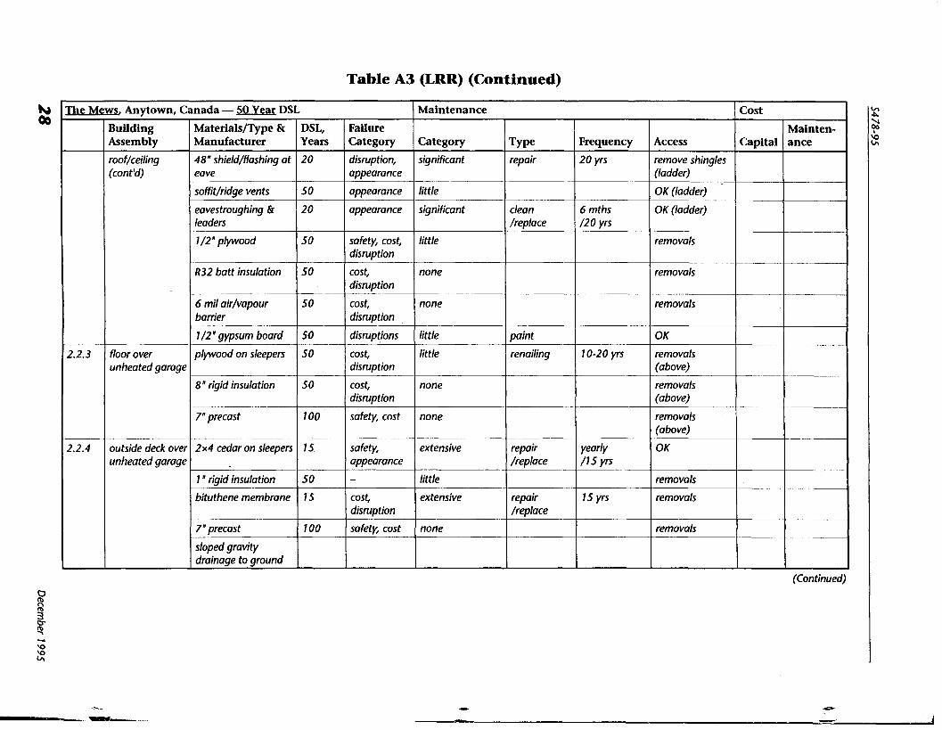
Table A3 (LRR) (Continued)
(Continued)
Failure Category
disruption, appearance
appearance
appearance
safety, cost, disruption
cost, disruption
cost, disruption
disruptions
cost, disruption
cost, disruption
safety, cost
safety, appearance - cost, disruption
safety, cost
The
2.2.3
2.2.4
Canada - SO Year DSL
MaterialsIType & Manufacturer
48 "shield/flashing at eave
soffit/ridge vents - eavestroughing & leaders
-.
1 /2" plywood
R32 butt insulation
6 mil air/vapour barrier
1 /2" gypsum board
plywood on sleepers
8 " rigid insulation
7"precast
2 x 4 cedar on sleepers
1 "rigid insulation
bituthene membrane
7" precast
sloped gravity drainage to ground
Mews, Anytown,
Building Assembly
roo f/ceiling (cont'd)
floor over unheated garage
outside deck over unheated garage
Maintenance
Category
significant
- -- little
significant
little
none
none
little
little
none
none
extensive
little
extensive
none
Cost
Capital DSL, Years
20
50
20
50
50
50
50
50
50
100
15
50
IS
100
TW repair
clean /replace
paint
renailing
repair /replace
repair /replace
Frequency
20 yrs
6 mths /20 yrs
10-20 yrs
yearly / I 5 yrs
15 yrs
Mainten- ance
--
-
Access
remove shingles (ladder)
OK (ladder)
OK (ladder)
removals
removals
removals
OK
removals (above)
removals (above)
removals (above)
OK
removals
removals
removals
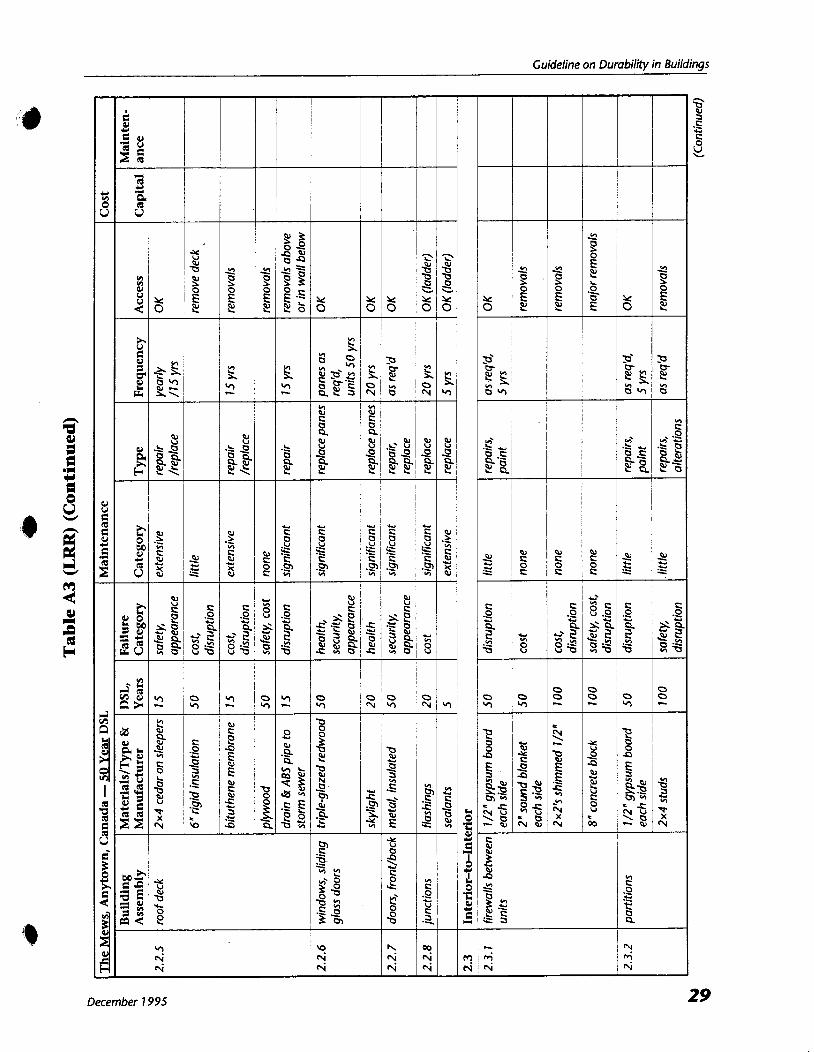
Guideline on Durabilitv in Buildinas
December 7 995 29

Table A3 (LRR) (Continued)
(Continued)
The Mews Anytown, Canada - SO Year DSL Cost Maintenance
Capital
-
3.
3.1
3.1.1
3.1.2
3.1.3
3.2
Failure Category
appearance, disruption
safety
safety
disruption, appearance
disruption, appearance
Category
none
little
none
little
significant
Mainten- ance -
2.3.3
2.3.4
Finishes, Furnishings, Fixtures
Interior Finishes
m e
renail
repairs
crack repair
MaterialslType & Manufacturer
1 /4 " subfloor (some areas)
5/8 " plywood
2x 1 0 joists
7/2" stippled gypsum board
taped, nailed
Building Assembly - floors
junctions
3.2.1
DSL, Years
100
100
100
1 00
20
pp
ceilings, walls
floors
bathrooms
-
Frequency
as req'd
as req'd
as req'd
Fixtures
paint
wall to wall carpet
tile shower walls
tile floors
sealants
Access
remove floor cover
remove floor cover
removals
OK
OK
10
15
20
20
5
appearance
appearance
health, appearance
disruption, appearance
appearance, health
safety, appearance
50 stair rails
significant
significant
significant
significant
-
safety, appearance
20
painted metal
3.2.2 exterior handrails
as req'd, repaint
2 weeks
20 yrs
20 yrs
touch-up repaint
clean/repair
repairs, regrout
repairs
significant
-- square steel anchored to wood parapet
significant
OK
OK
OK
OK
OK
extensive
paint
-
paint
replace
5 yrs
5 yrs
OK
- 5 yrs OK
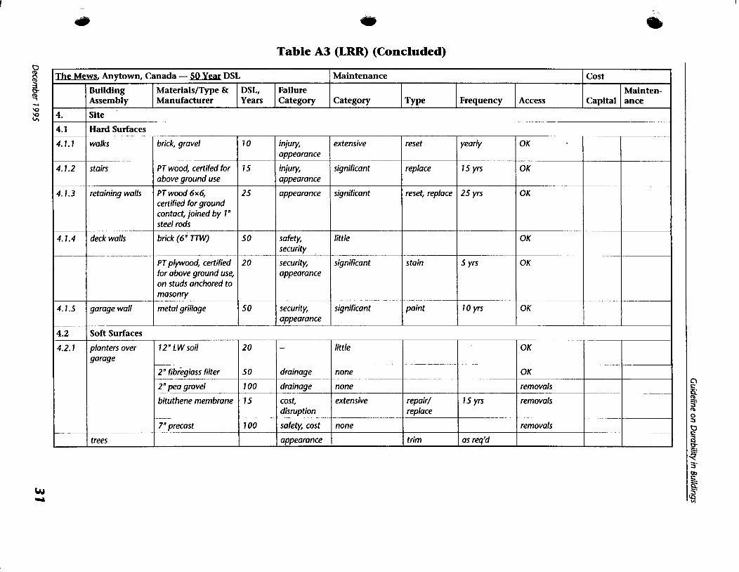
a Table A3 (LRR) (Concluded)
The Mews Anytown, Canada - 50 Year DSL
Failure Category
Maintenance
4.
4.1
4.1. 1
4.1.2
4.1.3
4.1.4
4.1.5
4.2
4.2.1
Category DSL, Years
Building Assembly
Cost
MaterialsIType & Manufacturer Capital
Site -
Hard Surfaces
' m e Mainten- ance
walks
stairs
retaining walls
deck walls
garage wall
Frequency Access
--
brick, gravel
PT wood, certifed for above ground use
PT wood 6x6, certified for ground contact, joined by 1 " steel rods
brick ( 6 W )
PT plywood, certified for above ground use, on studs anchored to masonry
metal grillage
extensive
significant
significant
little
significant
significant
Soft Surfaces
yearly
15 yrs
25 yrs
5 yrs
10 yrs
reset
replace
reset, replace
stain
paint
OK
OK
OK
OK
OK
OK
10
15
25
50
20
50
injuv, appearance
injurv, appearance
appearance
safety, security
security, appearance
security, appearance
-- -
15 yrs
as req'd
planters over garage
trees
20
50
100
15
100
OK
OK
removals
removals
removals
12 " L W soil
2 "fibrkglass filter ---
2" pea gravel --
bituthene membrane
7"precast
-
drainage
drainage
cost, d is~pt ion
safety, cost
appearance
little
none
none
extensive
none
repair/ replace
trim
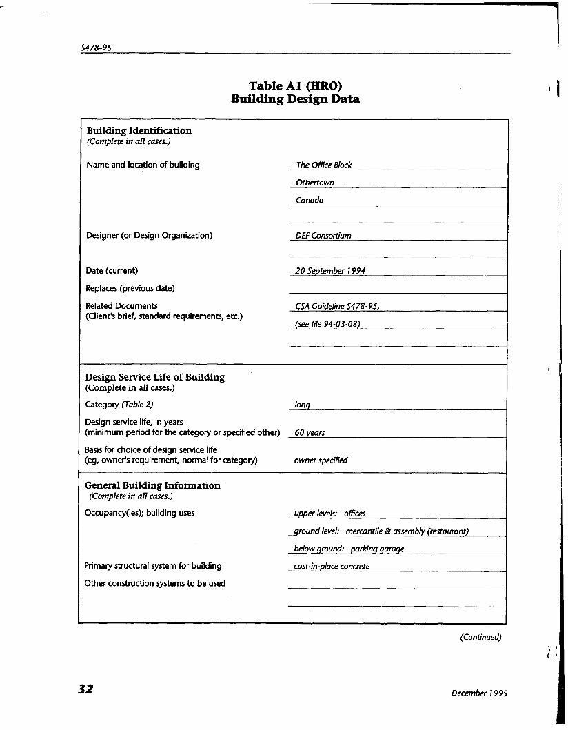
Table A1 (HRO) Building Design Data
Building Identification (Complete in all cases.)
Name and location of building The Office Block
Othertown
Canada
Designer (or Design Organization) DEF Consortium
Date (current) 20 September 1994
Replaces (previous date)
Related Documents CSA Guideline 5478-95, (Client's brief, standard requirements, etc.)
(see file 94-03-08)
Design Service Life of Building (Complete in all cases.)
Category (Table 2) long
Design service life, in years (minimum period for the category or specified other) 60 yean
Basis for choice of design service life (eg, owner's requirement, normal for category) owner specified
General Building Information (Complete in all cases.)
Occupancy(ies); building uses upper levels: offices
ground level: mercantile & assembly (restaurant)
below ground: parking garage
Primary structural system for building cast-in-place concrete
Other construction systems to be used
(Continued)
December 7 995
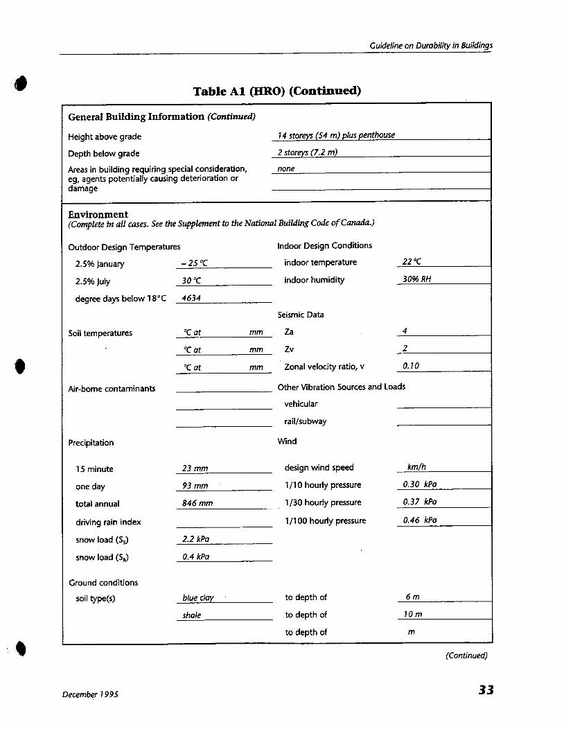
Guideline on Durability in Buildings
Table A1 (HRO) (Continued)
General Building Information (Continued)
Height above grade 7 4 storeys (54 m) plus penthouse
Depth below grade 2 storeys (7.2 m)
Areas in building requiring special consideration, none eg, agents potentially causing deterioration or damage
Environment (Complete in all cases. See the Supplement to the National Building Code of Canada.)
Outdoor Design Temperatures Indoor Design Conditions
2.5% January - 25 "C indoor temperature 22 "C
2.5% July 30 "C indoor humidity 30% RH
degree days below 18°C 4634
Seismic Data
Soil temperatures "C at mm Za 4
"C at mm Zv 2
"C at mm Zonal velocity ratio, v 0.70
Air-borne contaminants Other Vibration Sources and Loads
vehicular
raillsubway
Precipitation Wind
15 minute 23 mm design wind speed km/h
one day 93 mm 111 0 hourly pressure 0.30 kPa
total annual 846 mm 1 I30 hourly pressure 0.37 kPa
driving rain index 111 00 hourly pressure 0.46 kPa
snow load (SJ 2.2 kPa
snow load (53 0.4 kPa
Ground conditions
soil type(s) blue clay to depth of 6 m
shale to depth of 70 m
to depth of m
December 7 995
(Continued)
33
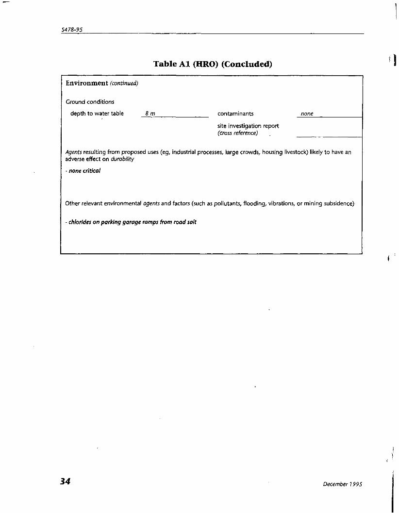
Table A1 (HRO) (Concluded)
Environment (continued)
Ground conditions
depth to water table 8 m contaminants none
site investigation report (cross reference) .
Agents resulting from proposed uses (eg, industrial processes, large crowds, housing livestock) likely to have an adverse effect on durability
- none critical
Other relevant environmental agents and factors (such as pollutants, flooding, vibrations, or mining subsidence)
- chlorides on parking garage ramps from road salt
December 7 995

Guideline on Durability in Buildinqs
Table A2 (HRO) Preliminary Design and Maintenance Options
(Continued)
December 7995
Notes Building Assembly Materials or Type
1.
1.1
1.2
1.3
1.4
2.
2.1
2.7.7
2.7.2
2.7.3
2.7.4
2.2
2.2.7
2.2.2
2.2.3
Maintenance Cost
Design Life, Years
m- Othertown, Canada - 5 0 Design Service Life
Structure ,
Capital Cost
Foundation
Parking Garage
mica1 Storey
Balconies
cast-in-place reinforced concrete
cast-in-place reinforced concrete
cast-in-place reinforced concrete
none
75
3-75
single ply membrane over rigid insulation over reinforced concrete
water barriers
I
note implications of failure
discuss slab protection to determine service life and capital vs maintenance costs
60+
60+ for vertical
Environmental Separations
Interior-to-Ground
2.2.4
none
high
roofs
basement walls
floor
junctions
*
roof
be greater or less than half- life of building
membrane is weak link; detailing is critical to DSL
detailing is critical
2.2.5 1 roof openings
2.2.6 1 roof junctions
:;n?o?ts; , slabs i
I
60+
i
waterproof bituminous membrane over reinforced concrete slab
none
20
Interior-to-Exterior (Above Ground)
waterproof bituminous membrane on concrete I 60
curtain wall - type 7
windows
curtain wall - type 2
reinforced concrete over granular fill
air, vapour, & water bummers
3 0
3 0
30-60
glass curtain wall
all tinted, sealed double glazed, non-opening
granite & glass curtain wall
60
major half-life replacement program
I DSL depends on mechanical support system selected; may
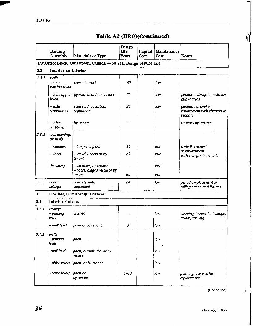
Table A2 (HRO)(Continued) 1 I'
(Continued) 2
December 1995
Notes Buiding Assembly
Design Life, Years Materials or 'I'ype
2.3
2.3.1
2.3.2
2.3.3
3.
3.1
3.7.1
3.1.2
Capital Cost
The Othertown, Canada - Design Service Life
Interior-to-Interior
Maintenance Cost
walls - core, parking levels
- core, upper levels
- suite separations
- other
concrete block
gypsum board on c. block
steel stud, acoustical separation
by tenant
60
20
20
- partitions , wall openings / (in mall)
3 0
60
- windows
low
low
low
- tempered glass
Finishes, Furnishings, Fixtures
Interior Finishes
periodic redesign to revitalize public areas
periodic removal or replacement with changes in tenants
changes by tenants
low
low
- I 60
60
periodic removal or replacement with changes in tenants
I - doors I - security doors or by 1 tenant
(in suites) / - windows, by tenant I - doors, hinged metal or by 1 tenant
ceilings - parking level
- mall level
walls - parking level
-mall level
- office levels
- office levels
floors,
low
low
low
1 low
1 low I 1 low
N/A
low
low concrete slab,
cleaning, inspect for leakage, delam, spalling
painting, acoustic tile replacement
finished I - paint or by tenant i s ( paint I paint, ceramic tile, or by tenant
periodic replacement of ceiling panels and fixtures ceilings , suspended
paint, or by tenant
paint or by tenant
5-1 0

Guideline on Durability in Buildings
Table A2 (HRO) (Concluded)
December 7 995
Buiding Assembly Materials or Type
T h e
3.7.3
3.2
3.2.7
3.3
3.3.7
3.3.2
4.
4.1
4.7.7
4.1.2
4.7.3
4.2 Soft
Maintenance Cost Notes
Design Life, Years
Office Block, Othertown, Canada - 50 Yea1 Design Service Life
Capital Cost
floors - parking '
level
- mall level
- ofice levels
4.2.7
4.2.2
grassed areas
flower and tree beds
5 60
60 5-20
7 0
low low
low low
low
Furnishings
fixed mall furniture
Fixtures
handrails
guards
low
low
60
60
cleaning, painting
cleaning, painting, inspection
Site
Hard Surfaces
resetting
resurfacing
Surfaces
60
60
pedestrian pavers, cast-in-place concrete
vehicular 1 asphalt over concrete
other
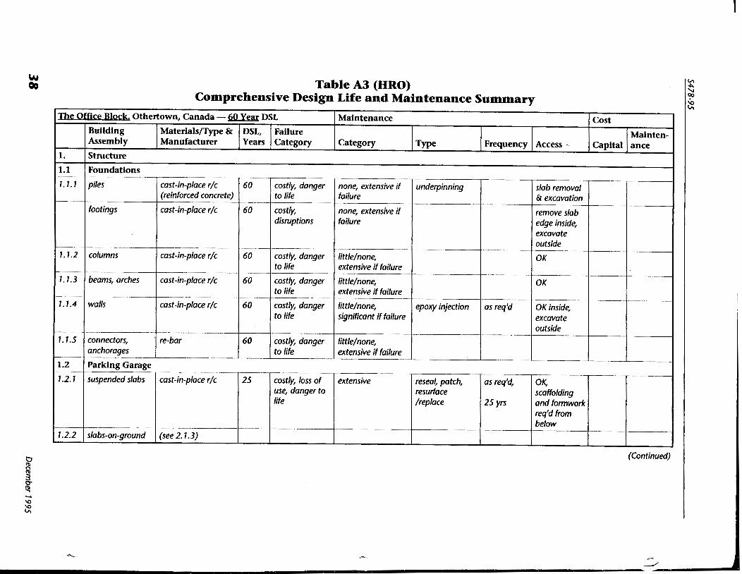
Table A3 (HRO) Comprehensive Design Life and Maintenance Summarv
1.1 1 Foundations I I
I
(Continued)
The Office Block. Othertown, Canada - 50 Year DSL
1.1.1
1.1.2
1.1.3
1.1.4
1.1.5
1.2
1.2.1
1.2.2
Maintenance Building
Cost
Mainten-
piles
footings
columns
beams, arches
walls
connectors, anchorages
Materials/Type & Assembly Capital
cast-in-place r/c (reinforced concrete)
cast-in-place r/c
cast-in-place r/c
cast-in-place r/c
cast-in-place r/c
re-bar
1.
DSL, Category ance
Parking Garage
Structure Manufacturer
Failure
60
60
60
60
60
60
suspended slabs
slabs-on-ground
Type Years
costly, danger to life
costly, disruptions
costly, danger to life
costly, danger to life
costly, danger to life
costly, danger to life
cast-in-place r/c
(see 2.1.3)
Category Frequency Access
none, extensive if failure
none, extensive if failure
little/none, extensive if failure
little/none, extensive if failure
little/none, significant if failure
little/none, extensive if failure
25
underpinning
epoxy injection
costly, loss of use, danger to life
as req'd
extensive
slab removal & excavation
remove slab edge inside, excavate outside
OK
OK
OK inside, excavate outside
reseal, patch, resurface /replace
as req'd,
25 yrs
OK, scaffolding and formwork req'd from below
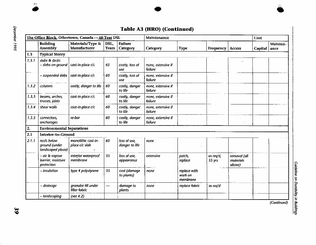
Table A3 (HRO) (Continued)
(Continued)
The
1.3
7.3.7
1.3.2
1.3.3
1.3.4
1.3.5
2.
2.1
2.1.1
Office Block. Othertown, Canada - 60 Yea DSL Maintenance Building Assembly Category
Cost
Capital Typical Storey
MaterialsIType & Manufacturer Type
Mainten- ance
slabs & decks - slabs-on-ground
- suspended slabs
columns
beams, arches, trusses, joists
shear walls
connectors, anchorages
DSL, Years Frequency
cast-in-place r/c
cast-in-place r/c
costly, danger to life
cast-in-place r/c
cast-in-place r/c
re-bar
Failure Category Access
Environmental Separations
Interior-to-Ground
60
60
60
60
60
60
roofs below ground (under landscaped plaza)
- air & vapour barrier, moisture protection
- insulation
- drainage
- landscaping
costly, loss of use
costly, loss of use
costly, danger to life
costly, danger to life
costly, danger to life
costly, danger to life
none, extensive if failure
none, extensive if failure
none, extensive if failure
none, extensive if failure
none, extensive if failure
none, extensive if failure
60
35
35
-
monolithic cast-in- place r/c slab
exterior waterproof membrane
type 4 polystyrene
granular fill under filter fabric
(see 4.2)
I
loss of use, danger to life
loss of use, appearance
cost (damage to plants)
damage to plants
patch, replace
replace with work on membrane
replace fabric
none
extensive
none
none
-
as req'd, 35 yrs
as req'd
removal (all materials above)
--
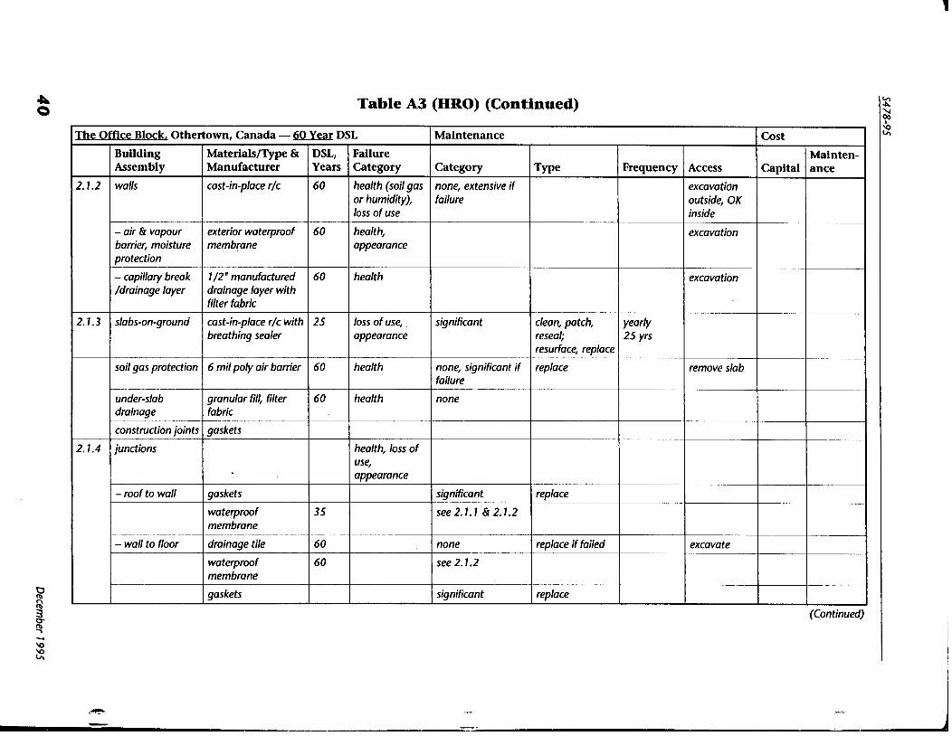
Q 0 Table A3 (HRO) (Continued)
(Continued)
The
2.1.2
2.1.3
Offlce Block, Othertown, Canada - 60 Year DSL Maintenance
Category
none, extensive if failure
significant
-
none, significant if failure
none
significant
see2.1.1 Sr2.1.2
none
see 2.1.2
significant
Building Assembly
walls
- air & vapour barrier, moisture protection
- capillary break /drainage layer
slabs-on-ground
soil gas protection
Cost
Capital
health
health, loss of use, appearance
Type
clean, patch, reseal; resurface, replace
replace
replace
replace if failed
replace
Mainten- ance
60
35
60
60
2.1.4
Failure Category
health (soil gas or humidity), loss of use
health, appearance
health
loss of use, appearance
health
Materialslm & Manufacturer
cast-in-place r/c
exterior waterproof membrane
1 /2 " manufactured drainage layer with filter fabric
cast-in-place r/c with breathing sealer
6 mil poly air barrier
Frequency
yearly 25 yrs
DSL, Years
60
60
60
25
60
Access
excavation outside, OK inside
excavation
excavation
remove slab
excavate
under-slab drainage
construction joints
junctions
- roof to wall
- wall to floor
granular fill, filter fabric
gaskets
gaskets
waterproof membrane
drainage tile
waterproof membrane
gaskets

Table A3 (HRO) (Continued)
(Continued)
The
2.2
2.2.1
2.2.2
Offlce Block. Othertown, Canada - 60 Yew DSL Maintenance
Building Assembly Category
Cost
Capital Interior-t+Exterior
type 7 (glass) curtain walls
- thermal insulation
- air/vapour barrier
- moisture protection
- cladding
- flashing
- seals
- drainage
- connectors, anchorages
windows
- glazing
- flashing
- seals
Materialsl'l'ype & Manufacturer w e
Mainten- ance
(Above Ground)
75 mm rigid glass fibre
22 ga prefinished metal pan
membrane between pan & window frame
6 mm tempered spandrel glass
stainless steel
tinted sealed double glazed units
prefinished aluminum
glazing beads
DSL, Years Frequency
Failure Category Access
30
60
30
75
30
60
30
60
7 0
costly, appearance, loss of use, loss of life
costly
costly, risk of injury costly, loss of use, danger to life
costly, danger to life
danger to life
costly
costly
costly
significant
extensive if failure
extensive if failure
extensive
extensive
none
significant
extensive if failure
significant
replace
replace
replace
clean, replace
replace
clean, replace
replace
replace
30 yrs
30 yrs
30 yrs
7 5 yrs
~ e a f - 1 ~ 30 yrs
-- -- -
-
30 yrs
seasonally, 30 yn
70 yrs
swing stage
removal of interior finish
swing stage
swing stage

Table A3 (HRO) (Continued)
2.2.3
Maintenance
Category
significant
extensive if failure
significant
significant
extensive
extensive
significant
none
significant
Othertown,
Building Assembly type 2 (granite & glass) curtain walls
- thermal insulation
- air/vapour barrier
- moisture protection
- cladding
- flashing
- seals
- connectors, anchorages
- windows (see 2.2.2)
- doors - swinging
- revolving
T y ~ e
replace
replace sealant
replace sealant
replace
replace
replace
replace
clean, lubricate, adjust hardware
Canada - 50
Materials/Type & Manufacturer
50 mm rigid glass fibre
--
sealant between precast backup panels
sealant between precast and window frame
granite panels
prefinished aluminum
sealant
stainless steel
metal, metal & glass metal & glass
Frequency 30 yrs
30 yrs
5 yrs
5 yrs
as reg 'd
as reg 'd
5 yrs
30 yrs
weekly 6 mths 6 mths
Yea DSL
DSL, Years
60
5
5
60
60
5
60
60
Access
swing stage
removal of interior finish
crane, swing stage
-
--
Failure Category costly, appearance, loss of use, loss of life
costly
costly, danger to life
costly, danger to life
-- costly, danger to life
costly
costly
danger to life
loss of use, security, risk of injury
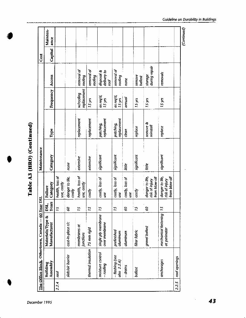
Guideline on Durabilitv in Buildinas
December 7 995

44 December 1995
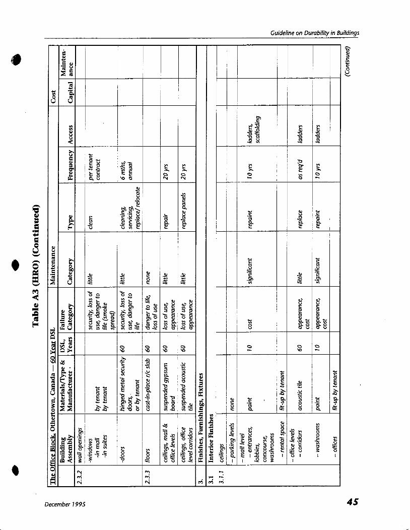
Guideline on Durability in Buildings
December 1995
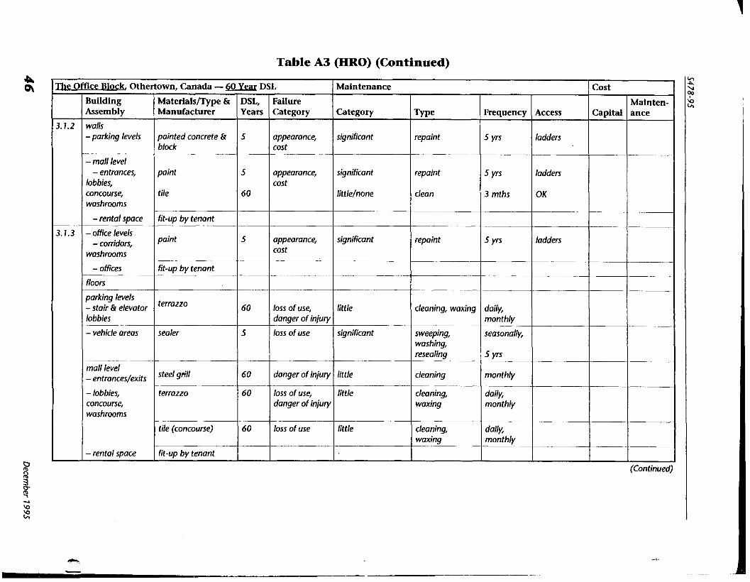
Table A3 (HRO) (Continued)
(Continued)
The
3.1.2
3.1.3
OLHce Block, Othertown,
Building Assembly
walls - parking levels
- mall level - entrances,
lobbies, concourse, washrooms
- rental space
- office levels - conidon,
washrooms
- offices
floon -- parking levels - stair & elevator lobbies
- vehicle areas
mall level - entrances/exits
- lobbies, concourse, washrooms
- rental space
Maintenance
Category
significant
significant
little/none
significant
little
significant
---
little
little
little
Cost
Capital
Canada - 60
Materialslme & Manufacturer
painted concrete & block
paint
tile
- fit-up by tenant
paint
fit-up by tenant -
terrazzo
sealer
steel grill
terrazzo
tile (concourse)
fit-up by tenant
Type
repaint
repaint
clean
repaint
cleaning, waxing
sweeping, washing, resealing
cleaning
cleaning, waxing
cleaning, waxing
Mdnten- ance
-
Year DSL
DSL, Years
5
5
60
5
. -
60
5
60
60
60
Frequency
5 yrs
5 yrs
3 mths
5 yrs
daily, monthly
~ea~onally,
5 yrs
monthly
daily, monthly
daily, monthly
Failure Category
appearance, cost
appearance, cost
appearance, cost
loss of use, danger of injury
loss of use
danger of injury
loss of use, danger of injury
loss of use
Access
ladders
ladders
OK
ladders
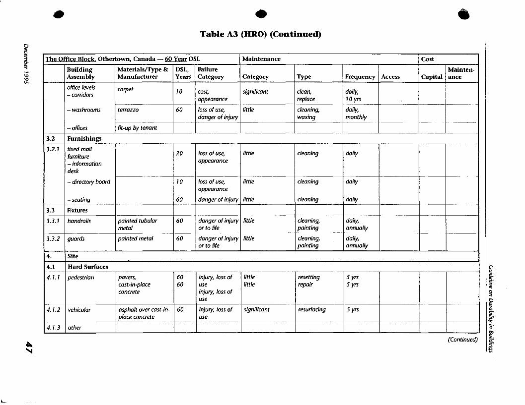
Table A3 (HRO) (Continued)
(Continued)
m e
3.2 - 3.2.7
3.3
3.3.1
3.3.2
4.
4.1
4.1. 1
4.1.2
4.1.3
Maintenance OWce Block, Othertown, Canada - 60 Year DSL
Category
significant
little
Building Assembly
office levels - corridors
- washrooms
- offices
Cost
Capital
Furnishings
' m e
clean, replace
cleaning, waxing
Materials/Type & Manufacturer
carpet
terrazzo
fit-up by tenant
Mainten- ance
fixed mall furniture - information desk
- directory board
- seating
Fixtures
handrails
guards
DSL, Years
10
60
Frequency
daily, 10 yrs
daily, monthly
loss of use, appearance
loss of use, appearance
danger of injury
danger of injury or to life
danger of injury or to life
Failure Category
cost, appearance
loss of use, danger of injury
Access
painted tubular metal
painted metal
Site
Hard Surfaces
2 0
10
60
60
60
little
little
little
little
little
cleaning
cleaning
cleaning
cleaning, painting
cleaning, painting
little little
significant
pedestrian
vehicular
other
daily
daily
daily
daily, annually
daily, annually
60 60
60
pavers, cast-in-place concrete
asphalt over cast-in- place concrete
injury, loss of use injury, loss of use
injury, loss of use
resetting repair
resurfacing
5 yrs S Y ~
5 yrs
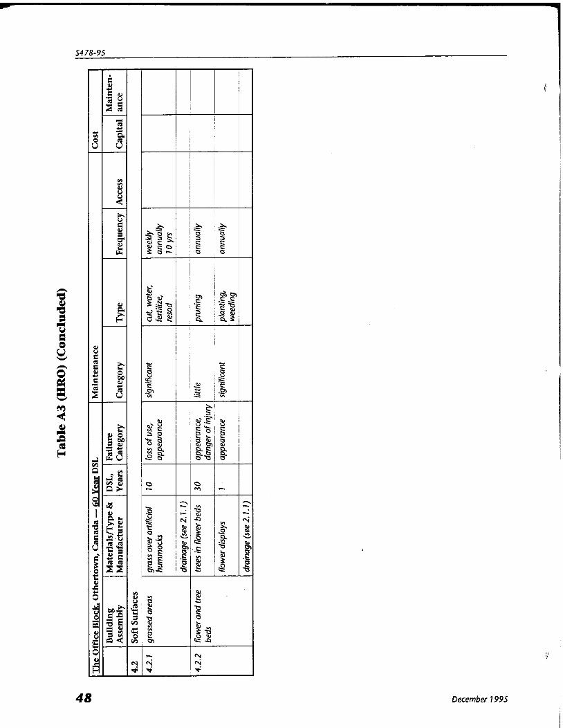
December 1995
Guideline on Durability in Buildings
4 Appendix B Costs of Premature Deterioration in Buildings
Note: This Appendix is included for information purposes only.
B1. The Costs of Repairs The costs arising from failing to achieve durability in buildings are both direct and indirect. The costs of unplanned major repairs or renovations required to reached the desired service life of a building are direct, but there are often substantial losses in revenue associated with disruptions to normal business while renovations and repairs take place. Information is hard to find on either category, but some indication of direct costs can be offered through two quite different approaches. One approach, used to assess the impact of ageing assets for the Advisory Board on the National
Research Council's (NRC) Construction Program (Dalgliesh, 1992), was to collect reports of rehabilitation projects, giving costs on a case-by-case basis. These reports indicated that the building envelope is generally the system most vulnerable to premature deterioration. In 1989, unsettled claims against Canadian architects and engineers for failing facades reached $50 million, and the Ontario New Home Warranty paid out $29 million for facades over a two year period. Only roofs give rise to more claims, but if the trend continues, facades will move into the lead. Office renovations deemed newsworthy usually report costs in the range of $5 - $30 million each, with some (Amoco Building in Chicago) going as high as $80 million (Clinton, 1991; Chevin, 1991). Upon identifying the building envelope as particularly vulnerable to durability problems, the Institute for Research in Construction of the NRC engaged a consultant to conduct a national assessment of the Canadian roofing and exterior cladding market (NRC, 1993), with instructions to estimate how much is being spent to correct premature failures. * In the end, this second approach was based on establishing expected service life benchmarks for roofing and cladding systems (Dell'lsola & Kirk, 1981). Premature failure was then defined as any performance condition requiring repair or replacement of the system before the benchmark date. The results of the study gave an average annual expenditure (in 1993 dollars), for roofing and exterior wall systems combined, of $7.5 billion. A conservative estimate of premature failure rate was calculated as 3% to 5%, ie, $235 - $380 million per year.
B2. Further Reading For reports referred to above and for further reading on the costs of premature deterioration, see Clause C2 in Appendix C.
December 1995

Appendix C Assessment of Environmental Conditions Note: This Appendix is included for information purposes only.
C l . General Environmental conditions are those chemical and physical exposures to which materials, components, or assemblies are subjected and which may result in failure due to material deterioration or movements. Service life of materials is determined by the interaction of the materials with their environments. Designing for durability implies the need to control or eliminate those agents promoting failure. In dealing with durability, two scales of environment must be considered: the macro-environment
adjacent to the assembly (atmospheric and ground conditions, including pollution, outside the building; heating, humidification, and ventilation conditions inside the building) and the micro-environment at the surface of, and within, materials and components. This Appendix provides information on
(a) the environmental agents which potentially can damage building materials and assemblies; (b) the assessment of component conditions and parameters; and (c) classifications of environmental severity for some common building materials.
C2. Environmenta l Agents That Can Affect Service Life Chemical action takes place continuously in many construction materials. These actions may be beneficial (gradual increase in concrete strength due to chemical changes in the cement) or detrimental (embrittlement of plastics exposed to ultraviolet radiation). Some chemical actions are entirely dependent upon constituents of the material but many are in response to agents such as moisture, temperature, and chemicals present in their environment, such as carbon dioxide (CO,) and sulphur dioxide (SO,). Frequently the action of one agent is dependent on the presence of another, moisture and oxygen being a common pairing. Table C1 lists the most common agents that may affect the durability of building components.
Physical action of environmental agents plays an important role in the deterioration of materials, components, and assemblies. The physical action of temperature and moisture fluctuation and/or gradient can either be direct (eg, cracking and joint movement (Beall, 1990; BRE, 1991) or indirect (eg, separation between cladding panels due to temperature drop or drying shrinkage can facilitate ingress of water and other agents into the wall assembly (ASTM, 1991) with the resulting damage being either chemical in nature (corrosion of cladding ties and anchors) or physical in nature (loss of thermal efficiency of insulation)).
C2.1 Water Water in the atmosphere in its various states (gas, liquid, or solid) interacts with material sutfaces in several forms: adsorbed moisture (low relative humidity); condensed water (high relative humidity eg, dew); and precipitation (eg, fog, rain, snow). Water plays a major role in the corrosion of metals, the decay of wood, and the deterioration of other materials, either as an agent of change or a means of transport of other agents. In the case of corrosion and other deterioration inside buildings and assemblies, the presence of water is usually a result of condensation on material surfaces. Most organic and many inorganic materials are porous and absorb moisture to varying degrees. Porous
materials which are saturated or nearly saturated may be fractured by the expansive forces exerted when the contained water freezes. Fluctuations in the moisture content of porous materials can cause them to I
expand and contract as moisture is absorbed and given off. These movements must be accommodated in the design. Thermal properties of insulation materials are detrimentally affected by absorption of $ 4
50 December 7 995 I
Guideline on Durability in Buildinqs
water. Organic materials such as wood will also decay if exposed to excessive moisture in the presence of oxygen and fungi. The formation of and growth of ice lenses in moist fine grained soils can lift buildings and cause serious
structural damage through frost heave of foundations and supported structures or by lateral displacement of retaining walls. The source of water may be from rainfall, moisture migration from the ground or the interior of a
building, or melt water when frost or ice formed on a surface melts. This latter source of water can be more damaging than the others since it produces saturation at just above the freezing point while leaving little opportunity for evaporation.
C2.2 Air Air, like water, is both an active environmental agent and a means of transport. Atmospheric oxygen (0,) acts as an agent which causes corrosion when present with moisture, and
allows decay to develop when in the presence of both fungi and adequate moisture. Carbon dioxide (CO,) acts as an agent of corrosion of reinforcing steel by reducing the alkalinity of concrete and, as a consequence, the passivity of the rebar surface. Air provides a means of transport of other environmental agents such as water and chlorides, with air
leakage through the building envelope being a major cause of problems.
C2.3 Air Contaminants The major air pollutants causing deterioration problems are oxides of nitrogen and sulphur, and salts. Precipitation becomes acidified as a result of dissolution of gases (Lipfert, 1987). Particulate matter in the air deposited on building surfaces can contribute to material deterioration. Hygroscopic deposits (eg, salts, dust, pollen) on material surfaces have been found to decrease the relative humidity at which a moisture film will form on a surface (ASTM, 1982).
@ Sulphur Dioxide The sulphur compounds, and especially sulphur dioxide (SO,), constitute the most important pollutant in the atmosphere today. The main source of sulphur dioxide has been identified as the use of fossil fuels (mainly coal with a relatively high sulphur content), including motor vehicle traffic. Consequently, the concentration of sulphur dioxide varies considerably depending on the distance from the sources of emission and the time of year. Its concentration in industrial areas and densely populated areas is sufficient to accelerate the deterioration of materials. The effect of SO, on the deterioration of materials is dependent on its deposition on material surfaces which in turn is dependent on other factors such as wind flow near the surface of the material, the presence of a film of moisture on the surface, and the nature of the surface. Proximity to a source of SO, has been demonstrated to be a major factor affecting deterioration of building materials.
Oxides of Nitrogen Oxides of nitrogen enter the atmosphere as a result of natural processes such as lightning and microbiological processes, through agricultural activities involving the use of nitrogen fertilizers, and by combustion of fossil fuel. In the presence of water, oxides of nitrogen can form nitric acid which could be detrimental for most building materials. However, the amount of nitric acid in the atmosphere is very small and its role on the deterioration of building materials is not clear.
Chlorides Although not normally considered as pollutants, chlorides from sea spray may be regarded as a form of particulate pollution. The carriage of sea-salt inland from coastal regions has long been recognized as an important contributor to atmospheric corrosion problems and stone deterioration in most maritime regions. It has been found that chloride deposition decreases with distance inland, with a consequent decrease in rate of corrosion. Although most of the decrease occurs within one to two kilometres from the shore, the effect can be significant a t much greater distances. Since sodium chloride can take up
December 7 995 51
water from the atmosphere at relatively low relative humidity, sea-salt deposits can pose severe durability hazards to metal building claddings, especially on surfaces sheltered from rain. Chlorides can also originate from industrial sources such as hydrochloric acid manufacturing plants and
from the combustion of coal, paper, and chlorine-containing plastics. These latter sources are also responsible for the presence of hydrochloric acid in the atmosphere. Chlorides from deicing salts are also found in abundance and are a major cause of much deterioration on North American roadway infrastructure.
C2.4 Soils and Ground Contaminants Any material placed in contact with contaminated soils and contaminated groundwater may be affected by the presence of the contaminants. The effect of soil contaminants depends on their combination, on their concentration, and on the soil type. Contaminants such as solvents (eg, gasoline) and oxidizing agents (eg, acids) can react chemically and dissolve or degrade plastics. Bacterial activity can affect directly or indirectly the deterioration of materials in soils. Sulphate reducing bacteria, found mostly on wet clay, boggy soils, and marshes, are a typical example of bacteria affecting corrosion of metals.
Naturally occurring constituents of the soil may promote deterioration of building materials, particularly in moist conditions. Salts dissolved in groundwater can migrate in porous materials in contact with the ground and cause efflorescence, a common problem with masonry in contact with the soil. Naturally occurring sulphates in some soils require the use of specially formulated concretes and masonry mortars to avoid their destruction due to the effects of the sulphates. Stray currents are extraneous direct electrical currents in the ground. When a metallic object is placed
in a strong current field, a potential difference develops across the object and accelerated corrosion occurs a t points where current leaves the object and enters the soil. This is especially pronounced in densely populated oil production fields and within industrial complexes containing numerous buried pipelines.
C2.5 Biological Agents Building materials can suffer from the direct action of living organisms (eg, deterioration of wood by fungi) or from the action of by-products of plant or animal life (eg, corrosion of metals by the action of sulphate reducing bacteria).
Microorganisms are usually classified according to their ability to grow in the presence or absence of oxygen. Fungi that cause deterioration of timber need oxygen and moisture (CBD 11 1, 1969). A moisture content of less than about 20% in timber is usually sufficient to prevent fungi from flourishing. Sulphate reducing bacteria are most prevalent in environments depleted of oxygen. Insect attack is predominantly a problem with timber and timber-based materials. The best known
insect problem with timber is attack by termites. Rodents such as mice and rats can cause considerable damage by gnawing organic materials and PVC
casings to electric cables. Birds and their nests and droppings can cause either mechanical damage (by pecking of soft materials) or by chemical damage (corrosion of steel bridges exposed to bird droppings). The major cause of damage from plants takes the form of disruption of foundations or clogging of
drains and gutters by roots. Trees absorb water from the soil which, for some soils, may result in differential settlement.
C2.6 Temperature One of the most significant effects of temperature is the thermal stress that is placed on all materials subject to variations in temperature. Roofing systems and cladding components are subjected to high temperatures in summer and very cold temperatures in winter and must expand and contract as the temperature cycles. Thermal stresses can cause buckling, bowing, and sometimes breakage of building components. Although most chemical processes are accelerated by an increase in temperature, a decrease in
temperature can also have a similar effect. This is the case for corrosion of metals where low surface
December 7 995
Guideline on Durability in Buildinqs
temperatures promote the condensation of vapour on the surface, providing an environment favourable to corrosion. However, if the surface temperature is high, drying of the surface will impede corrosion.
C2.7 Solar Radiation Organic materials such as polymers and wood may deteriorate if exposed to solar radiation. Solar radiation a t the earth's surface has been considerably altered by filtration through the atmosphere. The highest energy wavelengths, corresponding to the shortest ultraviolet wavelengths emitted by the sun, are absorbed by ozone in the upper atmosphere so that only UV radiation having the lowest energy is received at ground level. When a material absorbs radiation, the energy level of one particular atom is raised. The excited atom
may return to i ts unexcited state by dissipating the energy by heat or other types of radiation without damage to the molecules. This is what usually happens when materials are irradiated with longer wavelength radiation such as visible light or infra-red radiation. If radiation contains enough energy, however, it may cause a chemical reaction which is manifested by a gradual change of the material properties such as embrittlement, yellowing, or fading of the colour. Sealants, as a result of long molecule scission when exposed to UV and subsequent cross-linking of the shorter molecular chains, may either crack or lose adhesion at the interface. Before solar radiation can affect a material it is necessary for radiation to be absorbed. The opacity,
texture, and colour of the surface has a considerable effect on the ability of materials to absorb radiation. The molecular arrangement of the materials determines the amount and type of waves that are absorbed. The amount of high energy UV reaching the ground decreases as the sun angle decreases. Consequently, shading organic material surfaces when the sun is high is an effective way to decrease deterioration due to UV radiation.
UV radiation also interacts with other agents such as temperature and moisture to produce an effect greater than the sum of individual effects (CBD 122, 1970). Solar radiation on building surfaces has a very important effect on surface temperatures. The daily cycle 0 of solar radiation can cause building surfaces to experience large temperature swings. This in turn results
in cyclic dimensional changes to the building materials and it may also increase the number of freeze- thaw cycles.
C2.8 Chemical Incompatibility Two materials in contact may cause or accelerate deterioration as a result of chemical interaction. Some examples are (a) galvanic corrosion between dissimilar metals (see Appendix E); (b) crazing or fracture of plastic in contact with certain sealants (BRANZ 242, 1985); (c) accelerated corrosion of steel and zinc in certain woods and wood containing certain preservative chemicals (ASTM STP 691, 1 980); and (d) corrosion of lead and some aluminum alloys in contact with moist concrete or mortar.
C3. Environmental Parameters C3.1 Time-of-Wetness Time-of-wetness has been found to be one of the most important parameters in materials deterioration. Corrosion, for example, takes place when the surface of the metal is covered by a film of water. The presence of that film of water on the surface of metals exposed to the atmosphere has been found to occur when the relative humidity is above 80 to 90 percent and the temperature is above freezing. Also, the time-of-wetness depends on details (eg, retention of moisture between surfaces; gravity water traps). With natural ventilation, the indoor relative humidity (RH) can approach the outdoor relative humidity, whereas with air-conditioning and space heating, the indoor relative humidity can be significantly lower than the outdoor relative humidity, especially during cold weather.
December 7 995
C3.2 Driving Rain Index (and Driving Rain Wind Pressure) In the absence of wind, rain does not generally wet vertical walls; it is the combination of rain and wind that wets vertical surfaces. Wind impinging on a facade during a rain storm will cause water to migrate to vertical troughs and cavities and to accumulate as it channels its way downwards over a building facade. The product of the annual average rainfall and annual average wind speed is an indicator of the likelihood of rain penetration. Figure C1 shows the driving rain index (the product of annual rainfall, m, and average wind speed, m/sec) across Canada (Boyd, 1963). The regions of sheltered, moderate, and severe conditions are based solely on the index figures, and should be modified as follows according to local conditions: (a) sheltered conditions are in districts where the driving rain index is 3 or less, excluding areas that lie within 8 km of the sea or large estuaries, where the exposure should be regarded as moderate; (b) moderate conditions are located in districts where the driving rain index is between 3 and 7, except in areas which have an index of 5 or more and which are within 8 km of the sea or large estuaries, in which exposure should be regarded as severe; and (c) severe conditions are located in areas with driving-rain index of 7 or more. Also, in areas of sheltered or moderate exposure, high buildings which stand above their surroundings
or buildings of any height on hill slopes or hill tops should be regarded as having an exposure one grade more severe than that indicated by the map. A less well known but possibly more useful measure for assessing windIrain effects is the new Driving
Rain Wind Pressure (DRWP) data from Environment Canada. It is incorporated with explanation for its application in CSA Special Publication A440.1 -M1990.
C3.3 Acidity of Precipitation Acidity of precipitation, expressed as pH, is determined by the quantities of substances in the atmosphere. The normal pH of rain, as a result of equilibrium with carbon dioxide and carbonic acid, is approximately 5.6. Organic acids and background air pollution levels can act to reduce pH levels to below 5.0 In general, pH levels much greater than 5.0 will have been influenced by alkaline particles. Figure C2 is a plot of pH levels as measured by current networks operating for various agencies in North America. Urban pH levels, because of local sources of pollutants, can be somewhat below the values shown in Figure C2. The importance of pH with respect to metallic corrosion is discussed in Appendix E.
C4. Macro-Environments The outdoor macro-environment is characterized by climatological and ground conditions, including pollution. Environments in the ground are affected not only by climatological conditions and pollution sources, but also by the nature of the ground constituents. As a result, environments in the ground are very complex and very variable both in space and time. The nature of the indoor environment depends primarily on the operational conditions for heating,
humidification, and air conditioning of the building, and the presence of moisture sources such as swimming pools and contaminants such as chlorides. There may be several distinct indoor environments within any multi-functional building.
C5. Micro-Environments Materials are influenced by the environment in their immediate vicinity, ie, the micro-environment. The micro-environment to which a material or component is exposed reflects the macro-environment acting adjacent to the assembly, modified by the assembly itself and the porosity and permeability of the materials and components. The micro-environment results from the complex interaction between the macro-environment and the building component and assembly. Although little can be done to modify the macro-environment (except indoors), the micro-environment can be controlled. Control of the micro- environment can be achieved from a fundamental appreciation and understanding of the various transport mechanisms by which agents in the macro-environment gain access to building components.
December 7 995
Guideline on Durability in Buildinqs
(il) The mechanisms of concern are those which govern the flow of air, water, and heat. Further guidance on environmental transport mechanisms through building envelopes is contained in the Commentary to Part 5 of the NBCC. In designing for durability one can either select a material to resist the effects of the environment, or the
environment must be altered to suit the material. Figure C3 illustrates some instances where the micro- environment can be altered to suit the material by simple alterations in the design of a detail. Figure C3 (a) shows that by a relatively simple change in the design of a lap joint, an undesirable water trap can be avoided. A similar condition where a channel member, placed in a position which favours collection of water,.can be modified in various ways to alter the micro-environment which would cause deterioration of the member. Figure C3 (e) shows a condition where a material resistant to the detrimental micro-environment is used to alter the micro-environment at the base of a column.
C6. Classification of Environmental Severity Once the micro-environment has been assessed, by educated guess, by environmental simulation test, or by monitoring of existing buildings, the environment can be classified in terms of severity. Since different materials are affected differently by different environmental agents, it is hardly conceivable that a single environment classification system could be used for all materials in a building. The Decay Hazard Map for North America, Figure C4, shows the decay potential, based on the combined effects of average daily precipitation and temperatures above threshold levels, for exposed wood in above-ground applications. Table C2 presents the classification system used in the CIB-FIP Model Code for reinforced concrete.
Essentially, the level of humidity, chloride concentration, temperature, and the presence of chemical agents are the main factors affecting the rate of deterioration of reinforced concrete. Table C3 presents an environment classification system for metals (eg, steel, zinc, copper, aluminum)
based on time-of-wetness (Table C3 (a)), level of SO, contamination (Table C3 (b)), and concentration of chlorides in the atmosphere (Table C3 (c)). Table C3 (d) makes use of the categories obtained from the first three tables to classify the environment in terms of its corrosivity. The lowest level of corrosivity corresponds to an environment in which negligible amounts of metal loss would take place whereas the highest level, designated as very severe (VS), would result in a fast deterioration of the metal. The corresponding level of protection necessary to ensure adequate durability should be selected based on the severity of the environment. Metals in environments classified as VL would probably not need protection while a metal in an environment with a VS classification would probably need an elaborate protection system. The level of protection necessary, however, also depends on local rates of deposition of SO, (see Clause C2.3) and the type of metal.
C7. References For reports referred to above and for further reading on the assessment of environmental conditions affecting building components, see Section C3 in Appendix C.
December 1995

Table C1 Environmental Agents That Can Affect Service Life
(See Clause C2.)
December 7 995
Agent
Moisture
Air constituents
Air contaminants
Ground constituents
Ground contaminants
Biological agents
Temperature
Solar radiation
Incompatible chemicals
Differential movements
Use or exposure
Type
solid (ice, snow), liquid (rain, condensation), gas (water vapour, humidity)
02, c02
oxides, particulates, sea spray
sulphates and other salts, acids (from decomposition of organic matter)
chemicals from spills and leaks, chlorides from road salt, induced electrical currents
microorganisms, i nsects, other animals, plants
UV (ultraviolet) radiation
between components (shrinkage and swelling), within massive materials (temperature gradient response), creep/flow
loading, abrasion, overloading
Clause No.
c2.1
(2 .2
(2 .3
c2.4
(2.4
(2 .5
C2.6
(2.7
(2.8
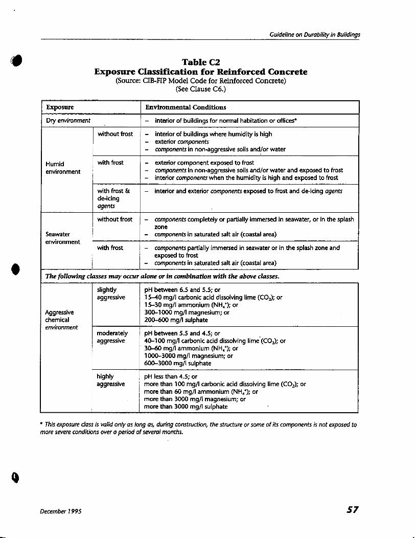
Guideline on Durability in Buildings
Table C2 Exposure Classification for Reinforced Concrete
(Source: CIB-FIP Model Code for Reinforced Concrete) (See Clause C6.)
This exposure class is valid only as long as, during construction, the structure or some of its components is not exposed to more severe conditions over a period of several months.
December 1995
Environmental Conditions
- interior of buildings for normal habitation or offices*
- interior of buildings where humidity is high - exterior components - components in non-aggressive soils andlor water
- exterior component exposed to frost - components in non-aggressive soils andlor water and exposed to frost - interior components when the humidity is high and exposed to frost
- interior and exterior components exposed to frost and de-icing agents
- components completely or partially immersed in seawater, or in the splash zone
- components in saturated salt air (coastal area)
- components partially immersed in seawater or in the splash zone and exposed to frost
- components in saturated salt air (coastal area)
Exposure
Dry environment
Humid environment
Seawater environment
without frost
with frost
with frost & de-icing agents
without frost
with frost
The following classes may occur alone or in combination with the above classes.
Aggressive chemical environment
slightly aggressive
moderately aggressive
highly aggressive
pH between 6.5 and 5.5; or 1540 mg/l carbonic acid dissolving lime (COJ; or 15-30 mgll ammonium (NH,'); or 300-1 000 mgll magnesium; or 200-600 mg/l sulphate
pH between 5.5 and 4.5; or 40-1 00 mgll carbonic acid dissolving l ime ' (~0~ ; or 30-60 mg/l ammonium (NH,'); or 1000-3000 mgll magnesium; or 600-3000 mgll sulphate
pH less than 4.5; or more than 100 mg/l carbonic acid dissolving lime (COJ; or more than 60 mgll ammonium (NH,'); or more than 3000 mg/l magnesium; or more than 3000 mg/l sulphate
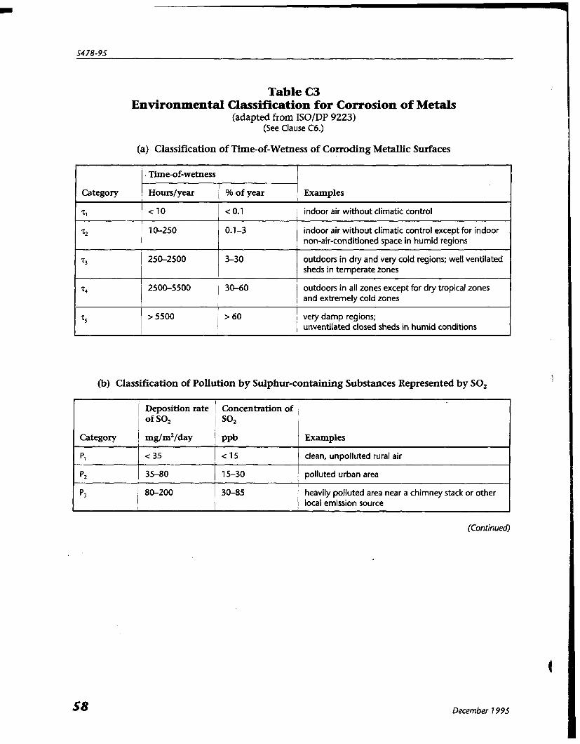
Table C3 Environmental Classification for Corrosion of Metals
(adapted from ISOIDP 9223) (See Clause C6.)
(a) Classification of Time-of-Wetness of Corroding Metallic Surfaces
(b) Classification of Pollution by Sulphur-containing Substances Represented by SO,
Category
71
22
=3
t
75
. Time-of-wetness
Hourslyear % of year Examples
c 10 c 0.1 indoor air without climatic control
10-250 0.1-3 indoor air without climatic control except for indoor non-air-conditioned space in humid regions
250-2500 3-30 outdoors in dry and very cold regions; well ventilated sheds in temperate zones
2500-5500 30-60 outdoors in all zones except for dry tropical zones and extremely cold zones
> 5500 > 60 very damp regions;
I unventilated closed sheds in humid conditions
(Continued)
Category
PI
p2
p 3
December 1995
Deposition rate Concentration of of SO2 SO2
mg/m2/day P P ~ Examples
c 35 < 15 clean, unpolluted rural air
35-80 15-30 I polluted urban area
80-200 30-85 / heavily polluted area near a chimney stack or other / local emission source
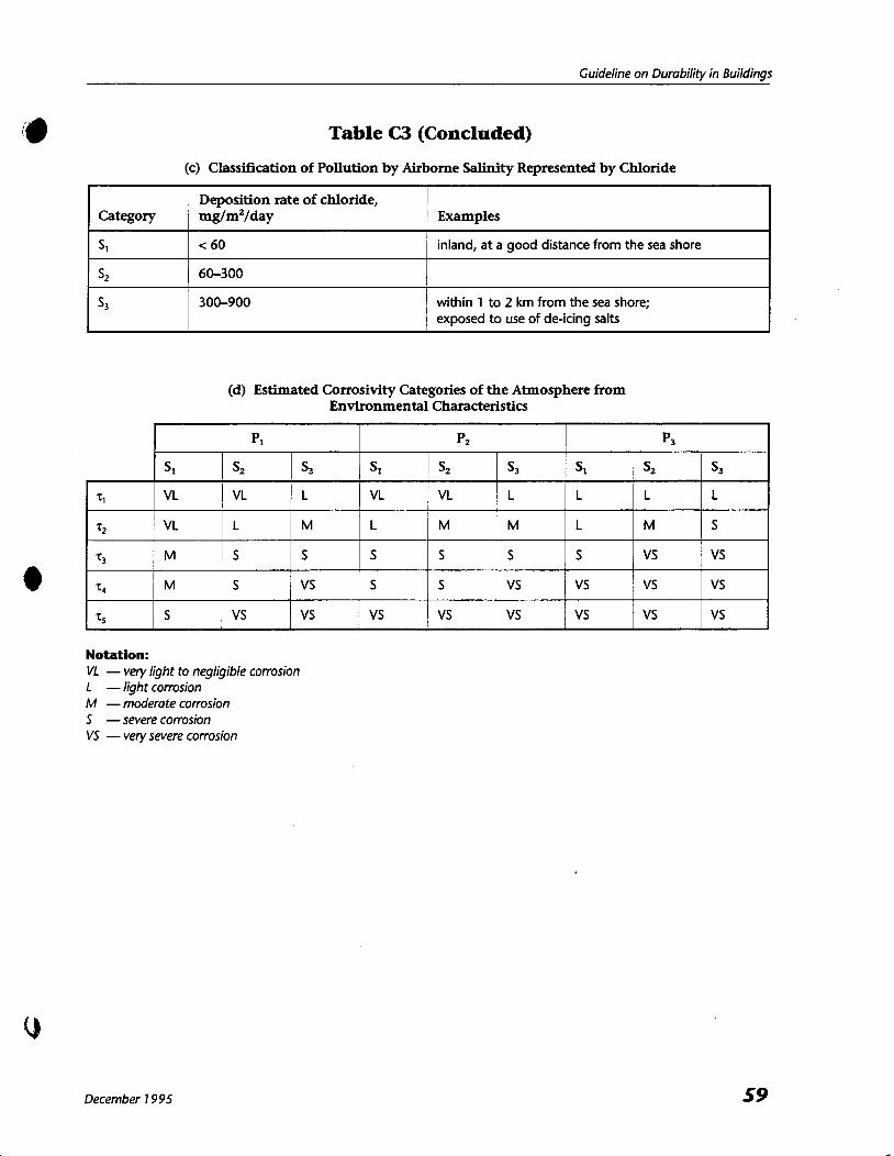
Guideline on Durability in Buildings
Table C3 (Concluded)
(c) Classification of Pollution by Airborne Salinity Represented by Chloride
(d) Estimated Corrosivity Categories of the Atmosphere from Environmental Characteristics
Category
s1
s2
s3
Notation: VL - very light to negligible corrosion L - light corrosion M - moderate corrosion 5 - severe corrosion VS - very severe corrosion
December 1 995
Deposition rate of chloride, mg/m2/day
< 60
60-300
300-900
Examples
inland, at a good distance from the sea shore
within 1 to 2 km from the sea shore; exposed to use of de-icing salts
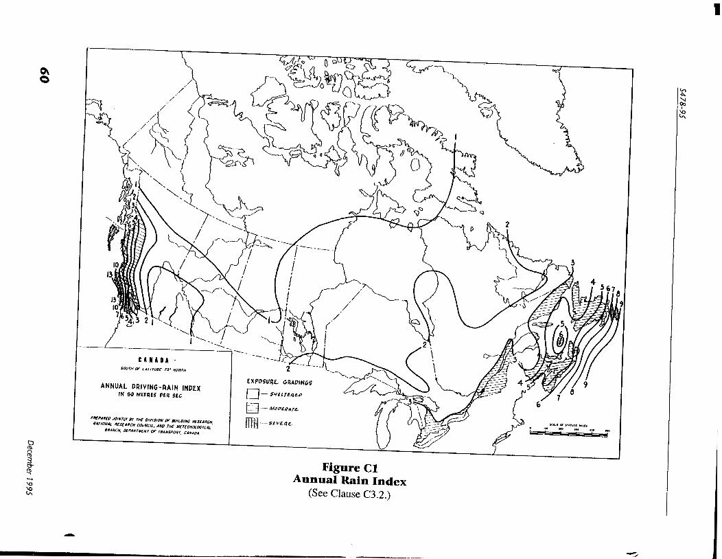
Figure C1 Annual Rain Index
(See Clause C3.2.)
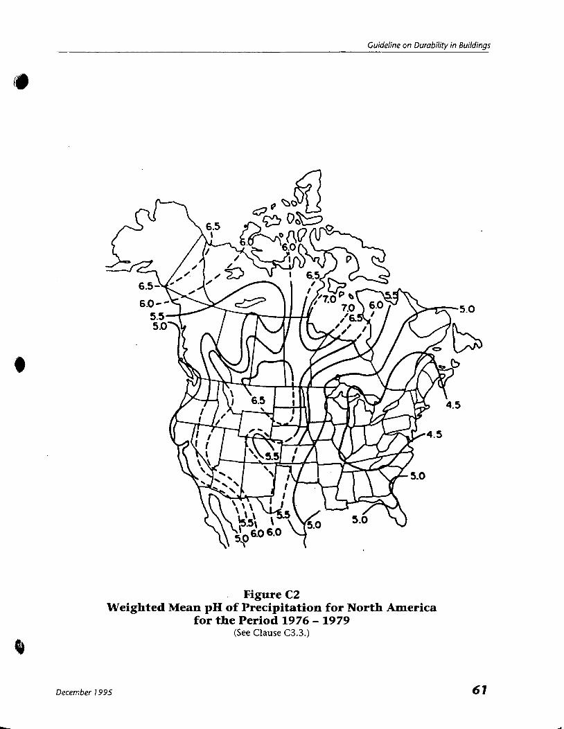
Guideline on Durability in Buildings
Figure C2 Weighted Mean pH of Precipitation for North America
for the Period 1976 - 1979 (See Clause C3.3.)
December 7 995
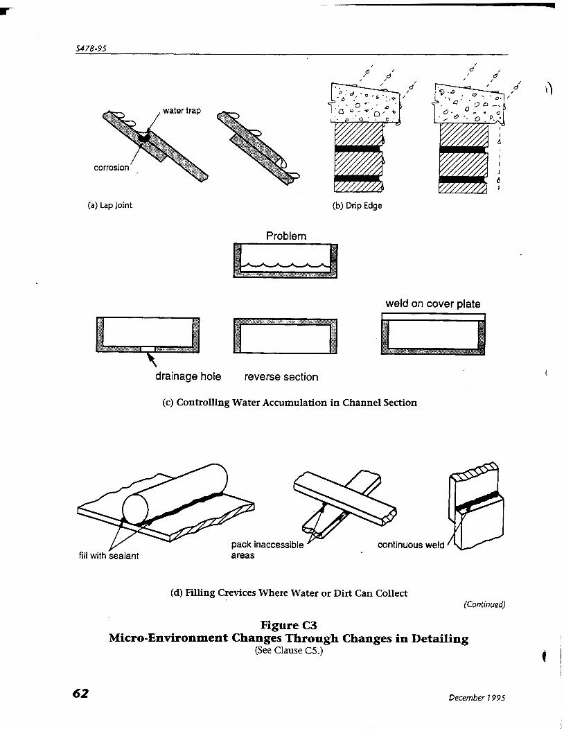
water trap
corrosion
(a) Lap Joint (b) Drip Edge
Problem
weld on cover plate
$ :* $9 1' I*.
drainage hole reverse section
(c) Controlling Water Accumulation in Channel Section
pack inaccessible continuous weld fill with sealant areas
(d) Filling Crevices Where Water or Dirt Can Collect (Continued)
Figure C3 Micro-Environment Changes Through Changes in Detailing
(See Clause C5.)
December 1995
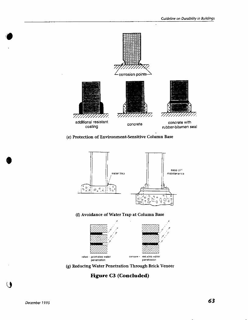
Guideline on Durability in Buildings
additional resistant concrete concrete with coating rubber-bitumen seal
(e) Protection of Environment-Sensitive Column Base
(f) Avoidance of Water Trap at Column Base
raked - promotes water concave - reduces water penetration penetration
(g) Reducing Water Penetration Through Brick Veneer
Figure C3 (Concluded)
December 1 995
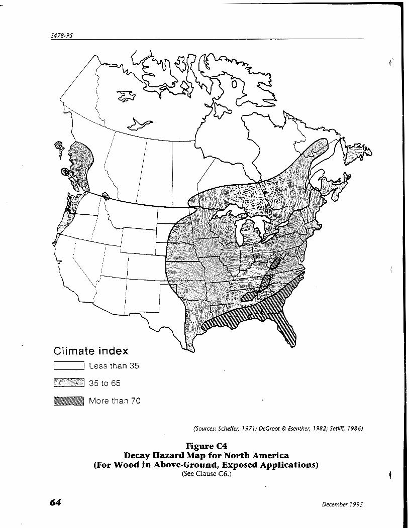
'-1 Less than 35
1-1 35 to 65 t ,... t ' . .
-74 More than 70
(Sources: Scheffer, 7 977; DeCroot & Esenther, 1982; Setlie 7 986)
Figure C4 Decay Hazard Map for North America
(For Wood in Above-Ground, Exposed Applications) (See Clause C6.)
December 7 9 95

+ Guideline on Durability in Buildings
Appendix D Deterioration Mechanisms for Building Materials and Control Note: This Appendix is included for information purposes only.
Dl . General This Appendix summarizes, in tabular form, the various possible mechanisms which may lead to the deterioration of building materials, conditions under which the deterioration process can proceed, and primary avoidance strategies. Initial sources for further reading are identified in the right hand column of the tables.
D2. Additional References The references in Section C4 of Appendix C provide additional reading on deterioration mechanisms and control strategies for various building materials.
December 7 9 95

Table D l Deterioration Mechanisms for Building Materials and Their Control
(Continued)
Material
Ground-soil
Ground-rock
Wood porous cracks due to shrinkage organic
Mechanism
Frost heave
Swelling and shrinkage of soils
Expansion of pyritic shales
Fungal decay
Subterranean Termites
Marine Borers
Thermal degradation
UV exposure
Drying shrinkage perpendicular to grain
Diierential movements due to changes in moisture content
Failures
Damage to building foundation or fabric, floor slope
Damage to building foundation or fabric, floor slope
Damage to building foundation or fabric, floor slope
Loss of material, strength, appearance
Loss of material, strength
Strength, loss of material
Strength
Surface degradation, coating breakdown
Splitting, damage to other components, floor misalignment, nail popping
Damage to interior fabric due to outward bowing of wood systems
Conditions for Process
Fine-grained soils & ground temperature <O°C
Expansive clays & changes in soil moisture content
Sustained moisture and oxygen with temperature 5-40°C
Access from ground, sustained moisture and oxygen, temperature S°C or more
---- Salt or brackish water (eg, piles)
Certain fire-retardants, high temperature and moisture (eg, unventilated roof spaces)
Exposure to sunlight
High initial moisture content, accumulated thicknesses perpen- dicular to grain (beams, stringers, plates)
Seasonal variations in moisture content, type of wood/slope of grain
Avoidance
Foundation location, type of soil
Drainage (avoid water traps), ventilation, preservatives
Preservatives, barriers, bait blocks
Preservatives, bamers
Stable fire-retardants, roof ventilation
Protective coatings and stains
Use dry wood, protective coatings, improved design
Use dry wood of good grade, design to allow movements
References
CBD 182
CBDs 62,84
CBD 152
USDA Wood Handbook CSA 080 Series CWC Wood Building Technology
CFS Canadian Woods, CBDs Ill, 112
ERE 299,345, CWC Wood Piles
CSA 080 Series ASTM ES20
CWC Wood Reference Handbook
Commentary D on NBC Part 4, CBD 244, CWC Wood Design Manual
Commentary D on NBC Part 4
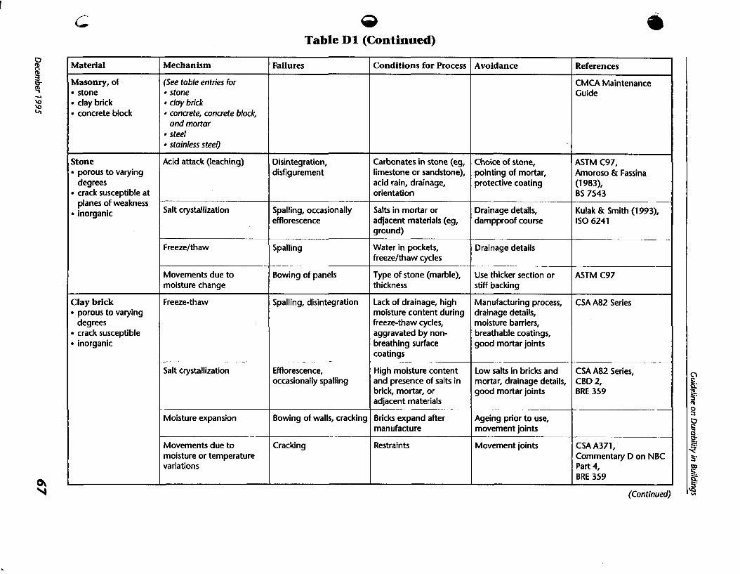
63 Table D l (Continued)
(Continued)
Material
Masonry, of stone clay brick concrete block
Stone porous to varying degrees crack susceptible at planes of weakness inorganic
Clay brick porous to varying degrees crack susceptible inorganic
Mechanism
(See table entries for stone clay brick concrete, concrete block, and mortar steel stainless steel)
Acid attack (leaching)
Salt crystallization
Freezelthaw
Movements due to moisture change
Freeze-thaw
Salt crystallization
Moisture expansion
Movements due to moisture or temperature variations
Failures
Disintegration, disfigurement
Spalling, occasionally efflorescence
Spalling
Bowing of panels
Spalling, disintegration
Efflorescence, occasionally spalling
Bowing of walls, cracking
Cracking
Conditions f o r Process
Carbonates in stone (eg, limestone or sandstone), acid rain, drainage, orientation
Salts in mortar or adjacent materials (eg, ground)
Water in pockets, freezelthaw cycles
Type of stone (marble), thickness
Lack of drainage, high moisture content during freeze-thaw cycles, aggravated by non- breathing surface coatings
High moisture content and presence of salts in brick, mortar, or adjacent materials
Bricks expand after manufacture
Restraints
Avoidance
Choice of stone, pointing of mortar, protective coating
Drainage details, dampproof course
Drainage details
Use thicker section or stiff backing
Manufacturing process, drainage details, moisture barriers, breathable coatings, good mortar joints
Low salts in bricks and mortar, drainage details, good mortar joints
Ageing prior to use, movement joints
Movement joints
References
CMCA Maintenance Guide
ASTM C97, Amoroso & Fassina (1 9831, BS 7543
Kulak & Smith (1 993), IS0 6241
ASTM C97
CSA A82 Series
CSA A82 Series, CBD 2, BRE 359
CSA A371, Commentary D on NBC Part 4, BRE 359

Table D l (Continued)
(Continued)
Material
Concrete, Concrete Block, and Mor ta r
porous to varying degrees cracks due to
shrinkage inorganic
Failures
Disintegration, appearance
Expansion, followed by disintegration
Expansion followed by disintegration
Strength, disintegration
Mechanism
Freeze-thaw
Sulphate attack
- Alkali-aggregate reaction
Acid attack
Condit ions fo r Process
High moisture content during freeze-thaw cycles, aggravated by chlorides and lack of drainage
Sulphates in ground water, bricks, coal stockpiles, or sea water
Leaching of lime Efflorescence, mortar disintegration
----
Biological attack Strength, disintegration
Vapour transfer, permeability
~
Contact with sewage (generation of acids)
High W/C ratio ~- - - -- - -
Shrinkage
Avoidance
Air entrainment, mix design, choice of aggregates, drainage details
Type of cement, mix design, drainage, low sulphate in brick
Cracking, damage of adjacent components (eg,
References
CSA A23.1, CBD 116
CSA A23.1, CBD 136
Silica or dolomite aggregates, requires moisture
Acids in industrial buildings - amount in contact. Permeability
CSA A23.1, S304.1, Commentary D on NBC Part 4
Appendix F of CSA 1423.1, CSA S413
Mix design, drainage details
Protective coatings
Mix design, construction
Creep
CSA A1 79
- - ---
CEB Bulletin 182
CSA A23.1, A371, A1 65 sequence, control joints, Series
Type of aggregates or cement additives, control of moisture
Protective coatings
brick veneer) reinforcement, curing and moisture control prior to use
CSA A23.1
CEB Bulletin 182
Deformation -- Design (greater thickness, pre-stressing)
Temperature movements
Abrasion
Large sections, hot climates
Heavy traffic, wind- driven particles
Cracking
Surface disintegration
Reinforcement, control joints
Protective toppings, choice of aggregate, additives

Table D l (Continued)
(Continued)
Material
Metals (all)
Mechanism
Galvanic corrosion
Diierential thermal movements
Failures
Many
Cladding damage
Steel non-porous inorganic
Drainage (avoid water traps), ventilation, protective coatings
Type of soil (test for resistivity, bacteria etc), protective coating, cathodic protection
Protective barriers, concrete mix, drainage details
Zinc coatings, stainless steel thickness
Drainage (avoid water traps), ventilation, protective coatings
Welding details, structural design
Conditions for Process
Electrolyte (moisture- filled porous material), metals electrically connected
Metals of different thermal coefficients connected to produce constraint stresses -
BS 5493, DIN 55928, CBD 170
BS 5493
ANSIIAWWA C105/A21.5
CSA A23.1, 541 3, CBD 224, 225
CSA A370, A371, Ailor (1 982), CIB 127
USDA Wood Handbook, BRE 301
CSA S16.1, Coveney (1 992), CIB 128
Corrosion: atmospheric environment
Corrosion: marine environment
-
Corrosion: soil environment
Corrosion: concrete environment
Corrosion: mhsonry envirbnment
Corrosion, timber environment
Fatigue
Avoidance
Choice of materials, electrical disconnection of adjoining metals
Design to allow movements, choice of metals
--- Connector failures, appearance, damage due to rust expansion
Corrosion of piles in splash zone
Pile failures, pipe failures
Failure of reinforcement or delamination of concrete
Failure of connectors, cracking of masonry
Failure of connectors and surrounding wood
Structural failure
References
Appendix F of this Guideline
Commentary D on NBC Part 4
Sustained moisture, oxygen, aggravated by acids and hygroscopic impurities
Sustained moisture, oxygen, aggravated by chlorides
Sustained moisture, oxygen or anaerobic bacteria, aggravated by soluble salts, stray electric currents
Sustained moisture, oxygen, chlorides or pH reduced by carbonation
Sustained moisture, '
oxygen, aggravated by salts
Sustained moisture, oxygen
Cyclic loads
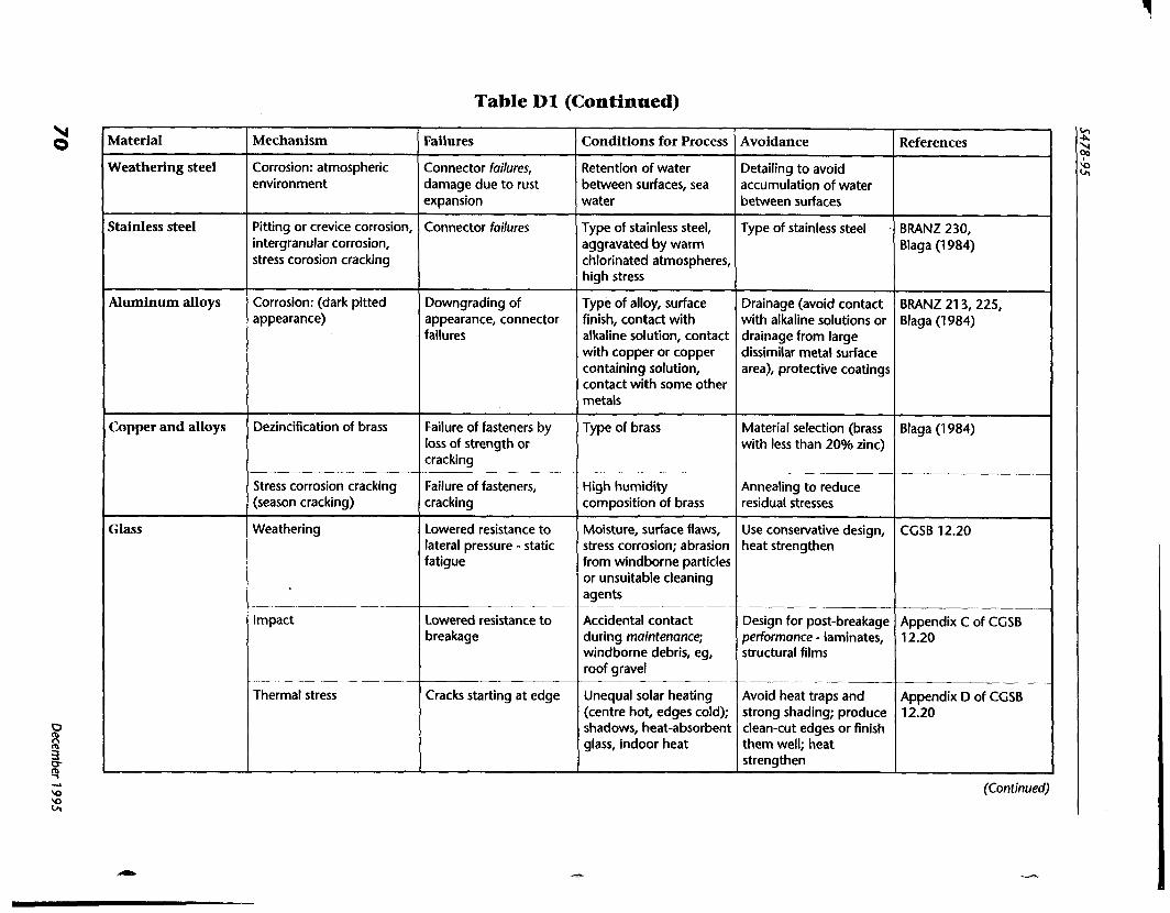
Table D l (Continued)
(Continued)
Material
Weathering steel
Stainless steel
Aluminum alloys
Copper and alloys
Glass
Mechanism
Corrosion: atmospheric environment
Pitting or crevice corrosion, intergranular corrosion, stress corosion cracking
Corrosion: (dark pitted appearance)
Dezincification of brass
--
Stress corrosion cracking (season cracking)
Weathering
Impact
Thermal stress
Failures
Connector failures, damage due to rust expansion
Connector failures
Downgrading of appearance, connector failures
Failure of fasteners by loss of strength or cracking
Failure of fasteners, cracking
Lowered resistance to lateral pressure - static fatigue
Lowered resistance to breakage
Cracks starting at edge
Conditions for Process
Retention of water between surfaces, sea water
Type of stainless steel, aggravated by warm chlorinated atmospheres, high stress
Type of alloy, surface finish, contact with alkaline solution, contact with copper or copper containing solution, contact with some other metals
Type of brass
High humidity composition of brass
Moisture, surface flaws, stress corrosion; abrasion from windborne particles or unsuitable cleaning agents
Accidental contact during maintenance; windborne debris, eg, roof gravel
Unequal solar heating (centre hot, edges cold); shadows, heat-absorbent glass, indoor heat
Avoidance
Detailing to avoid accumulation of water between surfaces
Type of stainless steel .
Drainage (avoid contact with alkaline solutions or drainage from large dissimilar metal surface area), protective coatings
Material selection (brass with less than 20% zinc)
Annealing to reduce residual stresses
Use conservative design, heat strengthen
Design for post-breakage performance - laminates, structural films
Avoid heat traps and strong shading; produce clean-cut edges or finish them well; heat strengthen
References
BRANZ 230, Blaga (1 984)
BRANZ 21 3, 225, Blaga (1 984)
Blaga (1 984)
CGSB 12.20
Appendix C of CGSB 12.20
Appendix D of CGSB 12.20
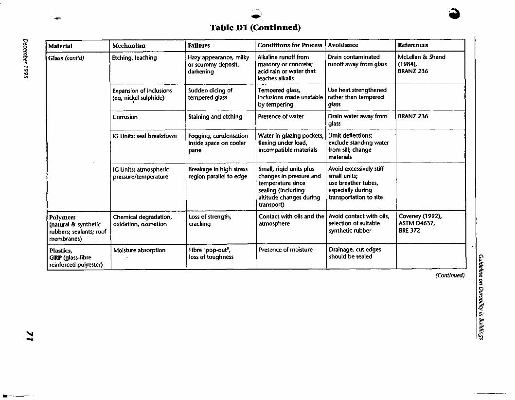
Table D l (Continued)
(Continued)
Avoidance
Drain contaminated runoff away tiom glass
Use heat strengthened rather than tempered glass
Drain water away from glass
Limit deflections; exclude standing water from sill; change materials
Avoid excessively stiff small units; use breather tubes, especially during transportation to site
Avoid contact with oils, selection of suitable synthetic rubber
Drainage, cut edges should be sealed
Conditions for Process
Alkaline runoff from masonry or concrete; acid rain or water that leaches alkalis
Tempered glass, inclusions made unstable by tempering
Presence of water
Water in glazing pockets, flexing under load, incompatible materials
Small, rigid units plus changes in pressure and temperature since sealing (including altitude changes during transport)
Contact with oils and the atmosphere
Presence of moisture
References
McLellan & Shand (1 984), BRANZ 236
BRANZ 236
Coveney (1992), ASTM D4637, BRE 372
Failures
Hazy appearance, milky or scummy deposit, darkening
Sudden dicing of tempered glass
Staining and etching
Fogging, condensation inside space on cooler pane
Breakage in high stress region parallel to edge
Loss of strength, cracking
Fibre npop-out", loss of toughness
Material
Glass (cont'd)
Polymers (natural & synthetic rubbers; sealants; roof membranes)
Plastics, GRP (glass-fibre reinforced polyester)
Mechanism
Etching, leaching
Expansion of inclusions (eg, nickel sulphide)
Corrosion
IG Units: seal breakdown
IG Units: atmospheric pressureltemperature
Chemical degradation, oxidation, ozonation
Moisture absorption

Table Dl (Concluded)
'Complete designations of referenced documents are listed in Section G4 of Appendix G. Acronyms for referenced documents are as listed below. ANSl/A WWA = American National Standards lnstitute/American Water Works Association ASTM = American Society for Testing and Materials RANZ = Building Research Association of New Zealand, Porirua NZ RE = Building Research Establishment Digest (U. K.) BS = British Standard (British Standards Institute) CBD = Canadian Building Digest (National Research Council of Canada) CEB = Comiti Euro-lnternational du Biton CFS = Canadian Forestry Service CGSB = Canadian General Standards Board CIS = Conseil Internationale du Bdtiment (International Council for Building Research Studies and Documentation) CMCA = Canadian Masonry Contractors' Association (of British Columbia and The Yukon) CSA = Canadian Standards Association CWC = Canadian Wood Council DIN = Deutsches lnstitut fur Normung (Germany) NBC = National Building ~ h d e (of Canada) USDA = United States Deportment of Agriculture (Forest Products Laboratory, Madison)
Material
GRp, other plastics, other FRP (fibre reinforced plastic)
Mechanism
Chemical attack under tensile stress
Fatigue induced by temperature and moisture fluctuation
Oxidation and photo- oxidation
Failures
Crazing and possible fracture
Surface cracking, degradation of mechanical properties
Degradation of mechanical properties, discolouration, hazing, dullness
Conditions for Process
Exposure to solvents or contact with some sealants, tensile stresses
Exposure to temperature and humidity fluctuation, U.V. light
Exposure to U.V. light
Avoidance
Avoid use of solvents, select compatible sealant
Surface protection from . U.V. exposure
Use of surface coating andlor U.V. absorber
References
CBD 122, BRANZ 241, Blaga (1 984)
BRE 69
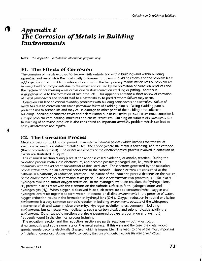
Guideline on Durability in Buildinqs
C) Appendix E The Corrosion of Metals in Building Environments
Note: This Appendix is included for information purposes only.
E l . The Effects of Corrosion The corrosion of metals exposed to environments outside and within buildings and within building assemblies and materials is the most costly unforeseen problem in buildings today and the problem least addressed by current building codes and standards. The two primary manifestations of the problem are failure of building components due to the expansion caused by the formation of corrosion products and the fracture of prestressing wires or ties due to stress corrosion cracking or pitting. Another is unsightliness due to the formation of rust products. This Appendix contains a short review of corrosion of metal components and should lead to a better ability to predict where failures may occur. Corrosion can lead to critical durability problems with building components or assemblies. Failure of
metal ties due to corrosion can cause premature failure of cladding panels. Falling cladding panels present a risk to human life and may cause damage to other parts of the building or to adjacent buildings. Spalling of concrete cover and delamination due to expansive pressure from rebar corrosion is a major problem with parking structures and coastal structures. Staining on surfaces of components due to leaching of corrosion products is also considered an important durability problem which can lead to costly maintenance and repairs.
E2. The Corrosion Process Metal corrosion of building components is an electrochemical process which involves the transfer of electrons between two distinct metallic sites: the anode (where the metal is corroding) and the cathode (the noncorroding metal). The essential elements of the electrochemical process involved in corrosion of metals are illustrated in Figure E l . The chemical reaction taking place at the anode is called oxidation, or anodic, reaction. During the
oxidation process metals lose electrons, e; and become positively charged ions, M+, which react chemically with the adjacent environment as discussed later. The electrons generated by the oxidation process travel through an electrical conductor to the cathode. Those electrons are consumed at the cathode in a cathodic, or reduction, reaction. The nature of the reduction process depends on the nature of the environment in which corrosion takes place. In acidic environments two processes can take place: hydrogen evolution and/or oxygen reduction. In the hydrogen evolution reaction, the hydrogen ions, H+, present in acids react with the electrons on the cathode surface to form hydrogen atoms and hydrogen gas (H,). When oxygen is dissolved in acid, electrons are also consumed when oxygen and hydrogen ions react together to form water. In neutral or alkaline environments in the presence of water, oxygen reduction results in the formation of hydroxyl ions (OH-). Oxygen'reduction in neutral or alkaline environments is a very common cathodic reaction in building environments because of the widespread occurrence of air and water in close proximity. Hydrogen evolution is less common in building environments, but can occur when pollutants such as carbon dioxide and sulphur dioxide acidify the environment. Other cathodic reactions are also encountered but are less common and are most frequently found in the chemical process industry. The oxidation reaction and the reduction reaction are partial reactions - both must occur
simultaneously and a t the same rate on the metal surface. If this were not the case, the metal would spontaneously become electrically charged, which is impossible. This leads to one of the most important principles of corrosion: during metallic corrosion, the rate of oxidation equals the rote of reduction.
December 1 995

The principal driving force for corrosion is the electrical potential difference existing between the anode and the cathode (the common battery is a corrosion cell which makes use of this potential difference to
(
generate electricity). The potential difference results from local variations within the environment to which a metal component is exposed andlor variations within the metal itself. These variations create a chemical imbalance which will provide the driving force for the current flow taking place during corrosion. Some of the most common variations are: variation in metal composition; variation of the concentration of dissolved elements in the electrolyte; and variation of temperature.
E2.1 Variation in Metal Composition This type of variation gives rise to dissimilar electrode, two-metal, or galvanic cells. A metal containing electrically conducting impurities on the surface as a separate phase, steel cladding fastened with copper fasteners, or steel coated with zinc are examples of this type of corrosion cell. Galvanic cells also include cold worked metal in contact with the same metal in its annealed condition or a stressed metal in contact with unstressed metal of the same composition. Some metals (eg, magnesium and zinc) or some phases of a given metal (eg, the ferrite phase in steel) have a greater potential to react with their environment than others (eg, copper and gold or the cementite phase in steel). If two metals or two metal phases in an electrolyte are connected together, a potential difference exists between the two metals. This potential difference produces electron flow between the two metals. The metal with greater potential to react (the more active metal) will become the anode and corrode while the other metal becomes the cathode. In the case of galvanized steel, for example, the zinc becomes the anode (which gradually corrodes but with little visible change) and the steel will act as the cathode and is therefore not affected until all the zinc is dissolved.
E2.2 Variation in the Concentration of Dissolved Elements in the Electrolyte This type of variation gives rise to concentration cells. These are cells having two electrodes of identical [ metal, each in contact with a solution of differing composition. The most important kind of concentration cell is called the differential aeration cell. The difference in oxygen concentration between two metal surfaces produces a potential difference and causes current to flow. The surfaces in contact with the solution containing the higher concentration of dissolved oxygen will become cathodic to the surfaces in contact with the solution containing the lower concentration of dissolved oxygen. The tendency of the corrosion process will be toward a reduction in oxygen concentration where it is highest.
E2.3 Variation in Temperature This results in the formation of differential temperature cells. Components of this type of corrosion cell are electrodes of the same metal, each a t a different temperature, in an electrolyte of uniform composition. This type of cell is of little practical implication for civil engineering structures. They are found in heat exchangers, boilers, and similar equipment.
E3. Factors Affecting Corrosion The major factors affecting metal corrosion encountered in building environments are passivation, solution acidity, dissolved oxygen, chlorides, and electrolyte resistivity.
E3.1 Passivation Passivation can be defined as the loss of chemical reactivity experienced by certain metals and alloys under specific environmental conditions. Certain metals and alloys become essentially inert under particular conditions and behave like the noble metals, eg, gold or platinum. The metals most subject to this kind of behaviour are the common engineering metals such as iron, aluminum, nickel, silicon, chromium, and alloys containing these metals. Although the phenomenon of passivation is complex in
t
December 7 995

Guideline on Durability in Buildinqs
, I ) nature and not yet completely understood, it is generally agreed that it results from the formation of a protective oxide film which acts as a barrier between the corrosive environment and the metal. It is this passive film which prevents many of the common metals such as stainless steel and aluminum from corroding rapidly in ordinary air. Some metals such as stainless steel and aluminum form their protective passive film in mildly corrosive environments such as the ambient air. However, other metals form their protective passive film only in more corrosive environments. This i s the case for iron which corrodes quite easily in moist air. When immersed in a highly concentrated nitric acid, a protective passive film is formed which protects the iron from further corrosion even in air. However, if the protective film is damaged, corrosion of the passivated iron would resume when exposed to moist air. As discussed later (see Clause E4.3), the corrosion of metals with a damaged passive layer may be more serious than without a passive layer. Steel also forms a protective passive film when exposed to an alkaline environment such as the one provided by cement paste. Metals not protected by a passive film are said to be active.
E3.2 Solution Acidity Solution acidity is a major factor affecting passivation and corrosion. Solution acidity is measured in terms of pH (negative logarithm of the concentration of H+ ions), where a pH of 0 is very acidic and a pH of 14 is very alkaline (high in OH- ions), with a pH of 7 being neutral (pure water). Rain is mildly acidic (pH 5.6), but SO, and CO, in the air can increase its acidity, especially in industrial areas (pH 3.5 to 4.5). Wet cementitious materials are strongly alkaline with pH greater than 12. Carbon dioxide in the air, however, can penetrate cementitious materials to react with Ca(OH), to remove the OH- ions (carbonation) thereby reducing the pH. With this variation in mind, aluminum passivates for pH between 4 and 8.5 and therefore corrodes in cementitious materials. Steel passivates for pH greater than approximately 10, and therefore does not corrode in concrete, except for porous concrete with little cover (eg, mortar) because of carbonation. Zinc passivates for pH between 8.5 and 12. Stainless steel
d passivates for pH between 3 and 14. Solution acidity also is a major factor affecting cathodic reaction. Hydrogen evolution is an important
cathodic process in acidic environments. As the solution acidity decreases, the amount of hydrogen available for the cathodic process decreases until, in a neutral or alkaline environment, hydrogen evolution i s not a contributing factor in corrosion. In solutions with a pH greater than 7, oxygen becomes essential in the corrosion process as discussed in the next section. The effect of pH on corrosion of steel and zinc is shown in Figure U.
E3.3 Dissolved Oxygen Oxygen reduction is the most common cathodic reaction. In acidic solutions the presence of oxygen increases the cathodic activity and, hence, the corrosion rate of non-passivated metals. For present building environments, dissolved oxygen from air (or from anaerobic bacteria in organic soils) is generally required for corrosion to occur. This is well illustrated by offshore structures where the greatest corrosion attack occurs at the water line where water, as an electrolyte, and oxygen are both abundant, while there is little corrosion in deep water because of the lack of oxygen. This is not always the case, however, since acidic conditions can occur in heavy industrial areas and corrosion can take place without dissolved oxygen.
E3.4 Chlorides Chlorides have the ability to create defects in the passive layer (not yet clearly understood) which become anodic, the passive layer becoming the cathode. This is called depassivation and occurs for reinforcing steel in concrete (alkaline solution) and for stainless steel. Corrosion of metals in the presence of chloride often takes the form of pitting which can lead to premature failure of structures subjected to cyclic loading or to leakage of containment structures. Failure of concrete parking structures due to chloride-induced corrosion (the rust expansion forces break the concrete cover) is one of the most expensive problems today.
December 7 995
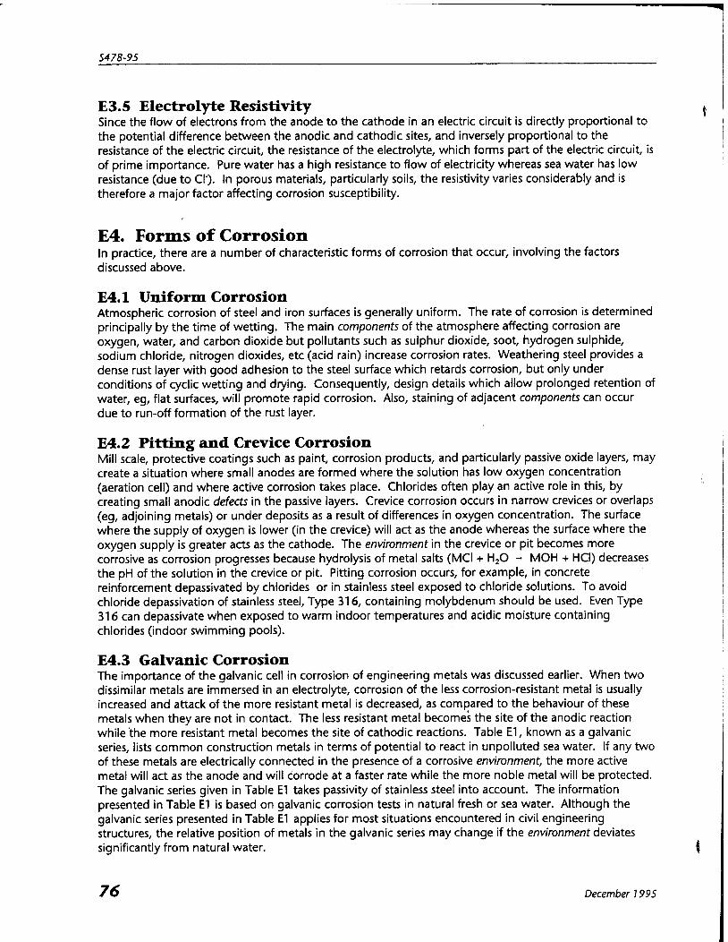
E3.5 Electrolyte Resistivity Since the flow of electrons from the anode to the cathode in an electric circuit is directly proportional to
6 the potential difference between the anodic and cathodic sites, and inversely proportional to the 1
I resistance of the electric circuit, the resistance of the electrolyte, which forms part of the electric circuit, is I
of prime importance. Pure water has a high resistance to flow of electricity whereas sea water has low I resistance (due to CI'). In porous materials, particularly soils, the resistivity varies considerably and is therefore a major factor affecting corrosion susceptibility.
E4. Forms of Corrosion In practice, there are a number of characteristic forms of corrosion that occur, involving the factors discussed above.
E4.1 Uniform Corrosion Atmospheric corrosion of steel and iron surfaces is generally uniform. The rate of corrosion is determined principally by the time of wetting. The main components of the atmosphere affecting corrosion are oxygen, water, and carbon dioxide but pollutants such as sulphur dioxide, soot, hydrogen sulphide, sodium chloride, nitrogen dioxides, etc (acid rain) increase corrosion rates. Weathering steel provides a dense rust layer with good adhesion to the steel surface which retards corrosion, but only under conditions of cyclic wetting and drying. Consequently, design details which allow prolonged retention of water, eg, flat surfaces, will promote rapid corrosion. Also, staining of adjacent components can occur due to run-off formation of the rust layer.
E4.2 Pitting and Crevice Corrosion Mill scale, protective coatings such as paint, corrosion products, and particularly passive oxide layers, may create a situation where small anodes are formed where the solution has low oxygen concentration (aeration cell) and where active corrosion takes place. Chlorides often play an active role in this, by creating small anodic defects in the passive layers. Crevice corrosion occurs in narrow crevices or overlaps (eg, adjoining metals) or under deposits as a result of differences in oxygen concentration. The surface where the supply of oxygen is lower (in the crevice) will act as the anode whereas the surface where the oxygen supply is greater acts as the cathode. The environment in the crevice or pit becomes more corrosive as corrosion progresses because hydrolysis of metal salts (MCI + H,O - MOH + HCI) decreases the pH of the solution in the crevice or pit. Pitting corrosion occurs, for example, in concrete reinforcement depassivated by chlorides or in stainless steel exposed to chloride solutions. To avoid chloride depassivation of stainless steel, Type 31 6, containing molybdenum should be used. Even Type 31 6 can depassivate when exposed to warm indoor temperatures and acidic moisture containing chlorides (indoor swimming pools).
E4.3 Galvanic Corrosion The importance of the galvanic cell in corrosion of engineering metals was discussed earlier. When two dissimilar metals are immersed in an electrolyte, corrosion of the less corrosion-resistant metal is usually increased and attack of the more resistant metal is decreased, as compared to the behaviour of these metals when they are not in contact. The less resistant metal become; the site of the anodic reaction while the more resistant metal becomes the site of cathodic reactions. Table E l , known as a galvanic series, lists common construction metals in terms of potential to react in unpolluted sea water. If any two of these metals are electrically connected in the presence of a corrosive environment, the more active metal will act as the anode and will corrode at a faster rate while the more noble metal will be protected. The galvanic series given in Table E l takes passivity of stainless steel into account. The information presented in Table E l is based on galvanic corrosion tests in natural fresh or sea water. Although the galvanic series presented in Table E l applies for most situations encountered in civil engineering structures, the relative position of metals in the galvanic series may change if the environment deviates significantly from natural water.
December 7 995

Guideline on Durability in Buildinqs
9 An important factor in a galvanic cell is the area effect. Because the rate of oxidation equals the rate of reduction in a corrosion cell, a small anode connected to a large cathode will corrode rapidly to provide the relatively large quantity of electrons that can be consumed in the reduction reaction taking place on the large cathode. In contrast, when a large anode is connected to a small cathode, the corrosion rate at the anode is relatively small because the amount of electrons that can be consumed at a small cathode is relatively small. In galvanized steel the zinc anode is large relative to the cathode (steel exposed by defects in the coating) and therefore corrodes slowly. A galvanized bolt connecting plain steel components, on the other hand, will lose its protective zinc coating rapidly. Similarly, a metal with a passive layer containing small defects or holes will corrode rapidly at the defects which are anodic to the cathodic passive layer. The distance between the anodic and cathodic areas also has an important effect on galvanic corrosion.
Accelerated corrosion due to galvanic effects is usually greatest near the junction, with attack decreasing with increasing distance from that point. The distance affected depends on the conductivity of the electrolyte.
E4.4 Intergranular Corrosion Intergranular corrosion occurs in stainless steels as a result of sensitization. Sensitization is a decrease of chromium content close to grain boundaries due to the precipitation of chromium carbides at the grain boundaries during heat treatment or welding. The precipitation of chromium rich carbides at grain boundaries sets up an intense galvanic reaction wherein the chromium depleted grain boundary acts as the anode and the chromium rich carbides act as the cathode. The methods used to control intergranular corrosion of stainless steels relate to the composition and heat treatment of the steel to minimize carbide precipitation. Certain aluminum-copper alloys may also show this type of corrosion.
E4.5 Stress Corrosion Cracking i Stress corrosion cracking of metals is defined as a cracking process resulting from the simultaneous action
of a corrosive environment and a sustained tensile stress. Steels with a tensile yield strength greater than 620 MPa are generally susceptible to stress corrosion cracking. Steels used in prestressing tendons and bridge cables are in this category. For the most part, the environments which are of major concern to the cracking of high strength steels are natural waters - rain water, sea water, and atmospheric moisture. Contamination with H,S (hydrogen sulphide) or nitrates following thunderstorms greatly increases susceptibility to stress corrosion cracking. Corrosion fatigue, which occurs under cyclic loading, is similar but occurs under a wider range of solution environments. Corrosion fatigue is generally not a problem in building environments.
E4.6 Hydrogen Embrittlement This is the only type of corrosion-related failure that occurs at the cathode. The processes involved in hydrogen embrittlement are not well understood One theory is that under certain conditions, atomic hydrogen, which forms a t the cathode due to reactions involving H+ ions, penetrates the steel and later combines as molecular hydrogen (H,) which expansively cracks the steel. Hydrogen embrittlement by itself is not often the cause of failures. However, since the source of atomic hydrogen is often corrosion, hydrogen embrittlement is often a contributing factor to stress corrosion cracking, as can occur in galvanized prestressing.
E5. Prevention of Corrosion The prevention of corrosion is achieved by. one or more of the following measures: (a) micro-environmental protection, including barriers, drainage, and ventilation as described in Clauses 7, 8, 9, and 11 of this Guideline; (b) choice of materials, for example to avoid galvanic corrosion cells or to resist the attack of corrosive
I solutions;
December 7 995

(c) protective coatings, including zinc, cadmium, or galvanum metal coatings which provide cathodic protection to steel. There are many other types of non-metallic coatings (see British Standard BS5493); C r and (d) methods, including cathodic protection by sacrificial anode or by impressed current using an inert anode, anodic protection for passivating metals, and additives which inhibit a chemical reaction or increase passivation.
E6. summary Corrosion is an electrochemical process involving anodic and cathodic chemical reactions, where corrosion takes place at the anode, and the flow of electricity through the metal, the solution, and across the anodic and cathodic interfaces. The process requires an aqueous solution containing dissolved
I I
oxygen (except in the case of acids). The process is retarded or stopped by the formation of a passive I I metal oxide layer which, however, may break down in the presence of chlorides or other agents (eg, SO,, CO,). The two basic types of corrosion cells causing building failures are differential aeration cells due to local differences in oxygen concentration in the solution and galvanic cells due to differences in oxidation potential of joined metals. I
The prevention of corrosion is achieved by a wide variety of measures involving design to avoid I
corrosive environments, choice of materials and protective coatings, and specialized methods such as 1 cathodic protection. I I
E7. References The references in Section C5 of Appendix C provide a more in-depth understanding of corrosion and corrosion prevention.
Table E l Galvanic Series for Metals and Alloys in Natural Fresh or Sea Water
(See Clause E4.3)
December 7 995 I

Guideline on Durability in Buildinas
Anode Cathode
7 - - - I - 0 - 9 -
I I
I I M-, M+ + e' I 2 ~ ' + 29; H p (acidic)
I I 0, + 4~ + 4e0+ 2H2 0 (acidic)
(passivity occurs if the I
metal oxide provides a 1 0, + 2H,0 + 4em+ 40Hg(neutral and protective layer) I
I alkaline) I \
\ Represents a change in the metal or solution
Figure E l The Corrosion Cell
(See Clause E2.)
December 1 995
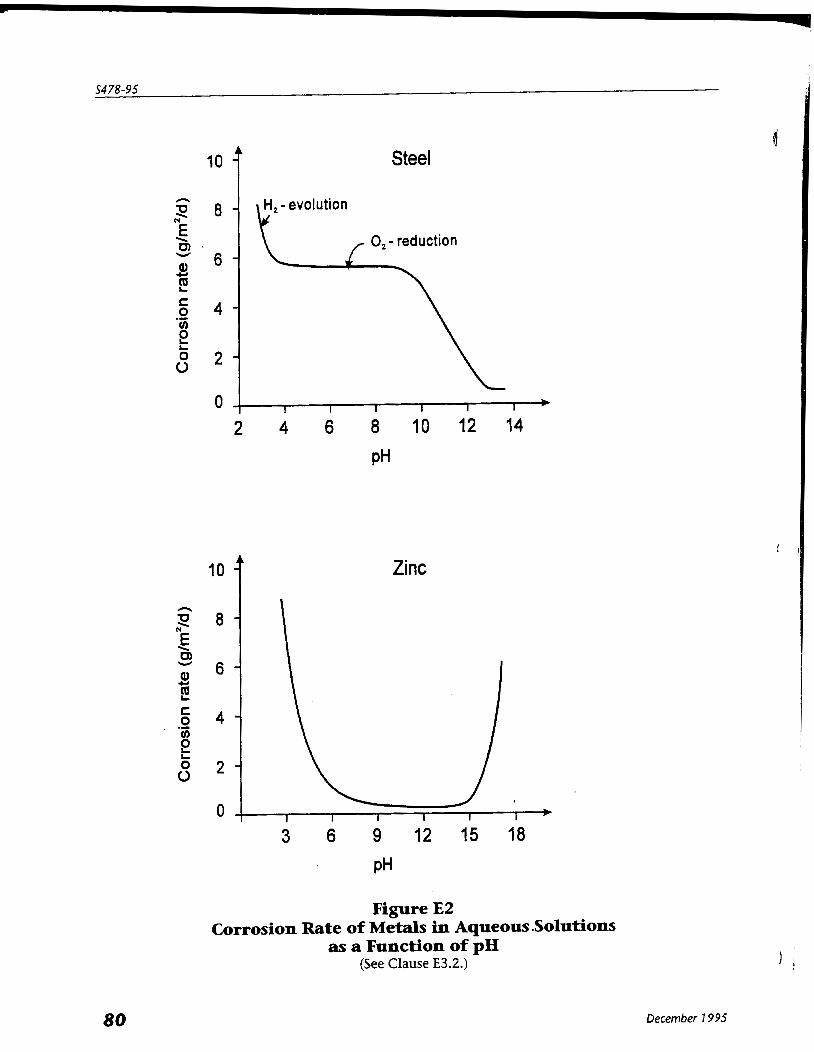
5478-95
A I 0 - Steel
m, C 0 4 - .- V)
2 L
0 2 - 0
Zinc
Figure E2 Corrosion Rate of Metals in Aqueous .Solutions
as a Function of pH (See Clause E3.2.)
December 7 995

Guideline on Durability in Buildings
AppendixF The Build3n.g Envelope
Note: This Appendix is included for information purposes only.
F1. General The building envelope is often the single most expensive component of current modern building, ranging from approximately 20% to 40% of the total cost. It also can be extremely difficult and expensive to repair. Building envelope failure most commonly reveals itself as moisture damaged cladding or roof components, condensation on walls and windows, drafts and uneven building temperatures, discolouration, and indoor air quality problems. The building envelope is composed of components and assemblies that are linked together in a
continuous plane to enclose conditioned space and to protect the contents and people within from the forces of the exterior environment. The building envelope can be divided into several parts, comprising (a) roofs above ground and their associated openings and penetrations including vents, hatches, and skylights; (b) exterior walls above ground and associated openings and penetrations including windows, doors, and vents; (c) soffits and cantilevered floors; (d) roofs below ground and their associated openings and penetrations including vents, hatches, and skylights; (e) exterior walls in contact with ground and their associated penetrations including vents; 3 (f) floors on ground; and (g) connecting joints and junctions.
None of these parts should be considered in isolation. Rather, an integrated "assembly approach" is necessary to ensure continuity between and among the multiple functions of each part at any location in a building. The principles for designing functional building envelopes were identified by Hutcheon (1 963) and are
illustrated by Brand (1 990). The principles governing envelope design also provide the key to identifying and eliminating or controlling the transport mechanisms that allow agents of deterioration to reach susceptible components.
F2. Roofs Not in Contact with Ground A principal function of the roof is to deflect and control moisture (rain, snow, ice).
Sloped roofs offer the easiest approach to handling rainwater and snow meltwater, and they can be easily waterproofed on the exterior with a variety of shingles, shakes, metal claddings, tiles, and slate. Minimizing leakage of moist air into enclosed spaces, eg, attics or interiors of closed roof panels, is critical to longterm durability; venting may be necessary to maintain dry conditions. ,
Flat (very low slope) roofs pose the greatest problems for managing rainwater, snow, and ice. Although flat roofs are the most difficult to waterproof, once provisions for gravity drainage have been provided, there are several waterproofing systems available for the purpose. A common system is the conventional three- or four-ply asphalt roof membrane. This assembly is set
over a layer of insulation which is protected from indoor air and moisture below by an effective air and vapour barrier applied over the structural roof deck. This traditional built up roofing system (BUR), has an expected service life of 20 years or more if there is a regular program of inspection and maintenance in effect. The protected membrane approach has been applied to many roofing membranes, with a resulting
4 increase in service life compared to the conventional BUR technology. In the protected membrane
December 1 995
system, the waterproofing and airlvapour barrier may be the same material, placed below the insulation instead of above it. Protected membrane systems are more costly to repair than BURS because it is more 0 difficult to trace and correct sources of leakage. There are several single- or double-ply waterproofing materials, such as PVC, EPDM, Hypolon, and
modified asphalt elastomeric membranes available as waierproofing for roofs. The durability of these materials has not been sufficiently tested to project service life expectancies. It is recommended that the evaluation of the various properties, performance, and method of installation of these products be carefully considered by the designer with expert input from the manufacturer. Building roofs used for vehicle parking, and all parking garage suspended floor slabs, though not part of
the building envelope, must be protected with traffic coating systems. These systems promote durability by waterproofing the deck, to protect against severe damage from corrosion of structural steel resulting from exposure to road salt, and by protecting the traffic surface from physical abrasion. Refer to CSA Standard S413, Parking Structures.
F3. Exterior Walls Not in Contact With Ground The common approach adopted for exterior walls for buildings in cold climates can be summarized as follows: (a) provide a continuous air barrier, with adequate structural support against wind loads; (b) ensure that the airlvapour barrier is flexible and allows for movement at joints; (c) provide continuous insulation, mechanically fastened to the supports and tight to the air barrier, preferably located so that the air barrier is on the warm side; (d) provide an effective and continuous vapour barrier on the high vapour pressure side; (e) provide an effective "rainscreen" cladding system to minimize rain penetration, supported in a way that minimizes the piercing of the insulation with thermal bridges; and (0 provide an air space when possible between the rainscreen and the insulation which is vented, drained, and pressure equalized to the exterior. Include tompartmentalization when required. A typical modern exterior wall system is made up of a cladding and supporting structure, incorporating
an insulation system together with vapour barrier and an air barrier system. The control of rain water penetration is achieved by either a rainscreen or a face seal approach. The traditional rainscreen wall assumes that water occasionally will enter the wall cavity behind the
cladding, but that drainage to the exterior will be provided through necessary flashings, drainage holeslgaps, and drips. For masonry cladding, this is st i l l the most common approach used in Canada and abroad. Shiplap and vertical siding panels of several materials perform under the same principles. The pressure equalized rainscreen approach was developed to control one of the major forces inducing
water penetration, air pressure difference across leakage paths in the cladding which drives water into the wall assembly. The face seal approach is reliant on all holes and joints being completely sealed, and requires frequent
inspections and maintenance with replacement of defective caulking. The durability of these systems varies according to geographic location and climate characteristics, the
indoor environment characteristics of humidity, temperature and pressure, materials chosen, and the design approach to obtain required performance characteristics, and quality of construction. Primary sources of high moisture levels in walls are rain water and snow meltwater that runs off the roof, window sills, or impermeable cladding directly onto the wall, and moisture carried by air leakage from within the building. Cracks in walls also may allow increased water ingress; therefore the design of the wall should incorporate appropriate movement joints to accommodate thermal, moisture, and structural movements. Unfortunately, the requirement for insulation of exterior walls of new buildings for the purpose of
energy conservation has durability implications in that claddings that do become wetted may take longer to dry out compared to similar claddings in uninsulated buildings where heat loss can assist the drying process, reducing the time-of-wetness. Experience has shown that different cladding systems have variable durability attributes and problems.
For example: 4
December 7 995
Guideline on Durabi/ity in Bui/dinqs
(a) The durability of masonry walls may be affected by high moisture levels, possibly leading to corrosion of metal components or to frost damage in masonry units subjected to freeze-thaw cycling while saturated. (b) The durability of precast wall systems requires inspection of anchorages potentially subject to corrosion or to movements related to creep of supporting structure, for extended life periods between 20 to 40 years. (c) Metal and glass curtain walls and structural glazing have evolved from face sealed systems to rainscreen technology. Well detailed systems may only require significant replacement of glazing after 20 to 25 years. (d) Metal building technologies are available either as a face sealed approach (traditional warehouse technology) or a structurally supported air barrier system and rainscreen cladding technology. The latter i s generally accepted as more durable, but corrosion control of anchorage systems needs to be well considered. (e) Exterior Insulation and Finish Systems (EIFS) are constructed with a polymer-modified stucco finish over a reinforcing mesh on an insulation board. Their durability is relianton high qualityworkmanship, especially at joints requiring use of site installed sealants to resist rain penetration. The design is essentially a face sealed system, although certain manufacturers have developed pressure equalized systems, and improved fire resistance ratings.
F4, Windows and Doors Durability is generally related to the individual components of frame and glass. Window frames made of aluminum or steel are required by CSA Standard CANICSA-A440 to be thermally broken for condensation control and typically have a life expectancy of 25 years or more. The deterioration of seals and gaskets leads to loss of ability of these assemblies to resist rain penetration and air leakage. The durability of sealed double glazed units is related to the edge seal and exposure to water, but they
) can perform satisfactorily for over 20 years.
F5. Roofs, Walls, and Floors in Contact With the Ground Assemblies in contact with the ground also form part of the protective envelope. In addition to their structural functions, they must be designed to manage or to prevent the entry of rain and ground water and control the entry of soil gases, to prevent ground contaminants such as radon gas from entering the building. Their durability is dependent on adequate drainage, well installed waterproofing systems, and special
attention to building perimeter tie-in details to prevent water infiltration.
F6, Soffits and Cantilevered Floors The common problem of corrosion of suspension systems and deterioration of components below cantilevered floors and within soffit spaces usually occurs when low temperatures within a "heated" soffit result in condensation of moisture attempting to exfiltrate the building through the enclosed space. In theory, the "hot soffit" design protects the soffit space components by making the enclosed space insulated and air-tight to the exterior (Cenge, 1990). In practice, unavoidable air leakage and numerous thermal bridges and penetrations into the space lower i t s temperature below the dew point of the building's air, leading to condensation and water related deterioration. The "cold soffit" approach can be a more effective solution to the problem. In this approach, the
exterior building wall system is insulated and sealed with an airlvapour barrier floor-to-floor, to minimize leakage into the soffit space, and the lower surface of the slab cantilevering over the soffit is insulated from below, leaving the space unheated. These precautions, plus airlvapour seals installed a t wall/floor slab intersections, are more structurally secure and easier to install than in the hot soffit system, and allow venting of the soffit so that components can dry out if some condensation does occur.
December 1 995
F7. Connecting Joints and Junctions The elements, components, and assemblies of a protective envelope are only as durable as the joints that connect them. joint design and construction is the most difficult task when assembling a protective envelope. The durability of joints is highly variable and depends on many factors including design, sequence of assembly, material suitability, and the service and environmental loads imposed. Connecting joints perform several important functions including the handling of thermal, moisture, and
load induced movements. They may, if so designed, facilitate the removal and replacement of deteriorated components or assemblies during maintenance or repair work, and simplify rainscreen detailing. Effettive joints can enhance the durability of abutting materials and assemblies, and should therefore be no less durable than the elements connected.
FS. References and Recommended Reading The references in Section G6 of Appendix C provide additional reading on the particular deterioration mechanisms and control strategies particularly associated with the building envelope.
December 7 995

Guideline on Durability in Buildings
3 Appendix G Bibliography
Note: This Appendix is included for information purposes only.
GI. General Supplemental Reading All, 1 993, Principle Guide for Service Life Planning of Buildings, (English edition available), Architectural Institute of Japan, Tokyo.
ASTM, 1982, Standard Practice for Developing Accelerated Tests to Aid Prediction of the Service Life of Building Components and Materials, ASTM Standard E632-82 (Reapproved 1988), American Society for Testing and Materials.
BSI, 1992, Guide to Durability of Buildings and Building Elements, Products and Components, British Standard BS7543:1992, British Standards Institute, London.
CIB, 1990, Feedback from Practice of Durability Data - Inspection of Buildings, CIB Report, Publication 127, lnternational Council for Building Research Studies and Documentation (Conseil lnternationale du Bbtiment).
CIB, 1 991, Feedback from Practice of Durability Data (Appendix) - hamples of Field Investigations, CIB Report, Publication 128, lnternational Council for Building Research Studies and Documentation (Conseil lnternationale du Bbtiment).
0 CMHC, 1 992, Review of Non-Destructive Test Methods for Assessing Strength, Serviceability and Deterioration in Buildings, Client Report A-801 3.1, Canada Mortgage and Housing Corporation, May 29, 1992.
ISO, 1984, Performance Standards on Building - Principles for their Preparation and Factors to be Considered, lnternational Standard I S 0 6241, lnternational Standards Organization.
Lacy, R.E., 1965, Driving-rain Maps and the Onslaught of Rain on Buildings, Building Research Current Paper 54, presented to the RILEMICIB Symposium on Moisture in Buildings, Helsinki, 1 6-1 9 August, 1965.
NBCC, 1 990 Supplement to National Building Code of Canada 1990, Commentaries on Part 4, Commentary D, Effects of Deformations in Building Components, Associate Committee of the National Building Code, National Research Council of Canada.
NBCC, 1 994, Commentary on Part 5, Wind, Water and Vapour Protection, of the National Building Code of Canada, 7990, Canadian Commission on Building and Fire Codes, National Research Council of Canada.
PWC, 1 990, Premature Failure of Building Envelopes and Structural Components, Public Works and Government Services Canada, April 1990 (287 pp).
PWC, 1993a, Cladding Study, Vol. 1 - A Literature Search (51 pp), Vol. 1 - Field Condition Survey (54 pp), Vol. 3 - Performance Monitoring (26 pp), Vol. 4 - Guidelines and Advisory Documents (48 pp), Public Works and Government Services Canada, March 1993.
PWC, 1 993 b, Performance and Durability of Building Materials, Public Works Canada, July 1 993 (61 4 pp).
PWC, 1 99 3c, Durability Guidelines for Design, Construction, Repair, and Maintenance of Parking Structures, Public Works and Government Services Canada, November 1993 (1 97 pp).
PWC, 1994a, Durability of Exterior Wall Systems, Public Works and Government Services Canada, March
, 1994 (1 97 pp).
December 7 995
PWC, 1 994 b, Performance and Durability of Window/Wall Assemblies, Public Works and Government \
Services Canada, May 1994 (1 50 pp).
Scott, P.J.B. and Davies, M., 1992, Microbially Induced Corrosion, Civil Engineering, Vol. 62, No. 5, American Society of Civil Engineering.
62. Supplemental References to Appendix B, Costs of Premature Deterioration in Buildings Anon, 1990, Spalling Brick Prompts Canadian Intervention, Engineering News Record, March 15, 1990, p. 17,18.
Anon, 1991, $30 Million Window Project, Class Digest, October 15, 1991.
Anon, 1 991, The Recent Renovation of 20-Storey First Interstate Bank Tower, Phoenix, Class Digest, October 15,1991.
Chevin, D., 1991, Non-Performing Seals - Britain Spends f 1 Billion/Year Resealing Failed Cladding, Building Magazine (UK), November 29, 1991.
Clinton, j., 1991 Facelift for a Towering Landmark - Coit Memorial Tower, Son Francisco, Concrete International, Vol. 13 No. 11.
Dalgliesh, W.A., 1992, Impact of Aging Building Assets, Advisory Board on the NRC Construction Program, Institute for Research in Construction, National Research Council of Canada.
Dell'lsola, A.J. and Kirk, S.J., 1981, Life Cycle Costing for Design Professionals, by McCraw-Hill Book Company.
Fairweather V., 1991, Chicago Tower Gets a New Skin, Civil Engineering, Vol. 61 No. 5, American Society D of Civil Engineering.
Halsall, P. and Kataila, J., 1988, Evaluation and Repair of a 60 Year Old Stone Veneer Cladding, Proceedings, Fourth Conference on Building Science and Technology, Toronto, February 18 and 19, 1988, p. 291 -306.
Mauarantani, R., 1991, Panels Speed Cladding job, Engineering News Record Vol. 227 No. 8.
NRC, 1993, National Roofing & Exterior Cladding Market Assessment, Hanscomb Consultants Inc., for the National Research Council of Canada, November 1993.
PMI, 1990, An Analysis of a Failure: The Structural Collapse at the Station Square Development, Wideman, M. Editor, Project Management Institute, February 1 990.
Post, N.M., 1991, Big job on Big Exterior in Big Appie - Manhattan Municipal Building, Engineering News Record, December 9, 1991.
Pym, D.V., 1 989, Yesterday, Today, The Future: From Roofs to Curtain Walls, presented at Encon I nsurance Managers Inc. Loss Control Seminars, Canada 1989-1 990.
63. Supplemental References to Appendix C, Assessment of Environmental Conditions ASTM, 1 980, Corrosion of Metal in Wood Products, Durability of Building Materials and Components, ASTM STP 691, Baker, A.J., ed., American Society for Testing and Materials.
ASTM, 1 982, Atmospheric Corrosion of Metals, ASTM STP 767, Dean, S.W. jr., and Rhea, E.C., eds., American Society for Testing and Materials.
December 7 995
Guideline on Durability in Buildings
ASTM, 1991, Water in Exterior Building Walls: Problems and Solutions, ASTM STP 1 107, T.A. Schwartz, ed. American Society for Testing and Materials, 1991.
Beall, C., 1 990, Building joint Movement, in Serviceability and Durability of Construction Materials, Proceedings of the ~i rst Materials Engineering congress, Denver, CO. August 13-1 5 1990, Vol. 1, pp. 51 7-526.
Boyd, D.W., 1963, Driving-Rain Map of Canada, Technical Note No. 398, Division of Building Research, National Research Council of Canada.
BRANZ, 1985, Glazing Plastics - 2. Design and Fixing, Building Information Bulletin 242, Building Research Association of New Zealand.
BRE, 1 991, Why do Buildings Crack?, BRE Digest 361, Building Research Establishment, May 1991.
CBD 1 1 1, 1 969, Decay of Wood, Baker, M.C., Canadian Building Digest 1 1 1, Division of Building Research, National Research Council of Canada.
CBD 1 22, 1 970, Radiation and Other Weather Factors, Ashton, H. E., Canadian Building Digest 122, Division of Building Research, National Research Council of Canada.
CBD 126, 1970, Influence of Orientation on Exterior Cladding, Crocker, C.R., Candian Building Digest 126, Divison of Building Research, National Research Council of Canada.
CSA A440.1 -M1990, User Selection Guide to CSA Standard CAN/CSA-A440-M90, Windows, Canadian Standards Association, Etobicoke, Ontario.
DeCroot, R.C. and Esenther, C.R., 1982, Microbial and Entomological Stresses on the Structural Use of Wood, pp 21 9-245 in Structural Use of Wood in Adverse Environments, Meyer, R.W. and Kellog, R.M. (eds),
I Van Nostrand Reinhold Co., New York.
Li pfert, F.W., 1 987, Effects of Acidic Deposition on the Atmospheric Deterioration of Materials, Materials Performance, Vol. 26, No. 7, July 1987, pp. 12-1 9.
NBCC, 1990, Supplement to the National Building Code of Canada 3 990, Commentaries on Part 4, Effects of Deformations in Building Components, Associate Committee of the National Building Code, National Research Council of Canada.
NBCC, 1994, Commentary on Part 5, Wind, Water and Vapour Protection, of the National Building Code of Canada, 7 990, Canadian Commission on Building and Fire Codes, National Research Council of Canada.
Robinson, C., and Baker, M.C., 1975, Wind-Driven Rain and Buildings, Technical Paper 445, NRCC 14792, Divison of Building Research, National Research Council of Canada.
Scheffer, T.C., 1971, A Climate lndex for Estimating Potential for Decay in Wood Structures Above Ground, Forest Products Journal, November, 1971.
Setliff, E.C., 1986, Wood Decay Hazard in Canada Based on Scheffer's Climate lndex Formula, The Forestry Chronicle, October 1986.
64. Supplemental References to Appendix D, Deterioration Mechanisms for Building Materials and Their Control 64.1 Referenced and Supplemental Documents Ailor, W.H., ed., 1982, Atmospheric Corrosion, John Wiley & Sons, New York.
Amoroso, C.C. and Fassina, V., 1 983, Stone Decay and Conservation: Atmospheric Pollution, Cleaning, I Consolidation and Protection, Materials Science Monographs, 1 1, Elsevier.
December 7 995
Ashurst, J. and N., 1 988, Stone Masonry in Vol. 1 of Practical Building Conservation, Halsted Press, New York.
Blaga, A., 1 984, Effect of the Environment on the Durability of Plastic-Based Materials, DBR Paper No. 1 22 1 , Division of Building Research, National Research Council Canada.
Coveney, V.A., 1 992, Natural and Synthetic Rubbers, Chapter 3 7 in Construction Materials Reference Book, Doran, D.K., ed., Butterworth-Heinemann Ltd.
Keenan, F.J., Boyd, S.]., Cooper, P.A., and Taylor, R.A., 1986, Limit States of Wood Structures, Morrison Hershfield ~imited, (out of print), Toronto, Canada.
Kulak, C.L. and Smith, I.F.C., 1 993, Analysis and Design of Fabricated Steel Structures for Fatigue: A Primer for Civil Engineers, Structural Engineering Report No. 190, University of Alberta, Canada.
Maurenbrecher, A.H.P. and Brousseau, R.]., 1993, Review of Corrosion Resistance of Metal Components in Masonry Cladding on Buildings, Internal Report No. 640, Institute for Research in Construction, National Research Council of Canada.
McLellan and Shand, 1984, Class Engineering Handbook.
Society of Wood Science and Technology, 1982, Structural Use of Wood in Adverse Environments, Van Nostrand Reinhold Co., Toronto, Canada.
USDA, 1 987, Wood Handbook, Forest Products Laboratory, United States Department of Agriculture, Superintendent of Documents, US Government Printing Office, Washington, DC.
64.2 Referenced Bulletins, Codes, and Standards
64.2.1 American National Standards Institute/American Water Works Association - ANSI/AWWA ClO5/A21.5-93, Polyethylene Encasement for Ductile-Iron Pipe Systems.
64.2.2 American Society for Testing and Materials - ASTM C97-90, Test Methods for Absorption and Bulk Specific Gravity of Dimension Stone;
D463 7-87, Specification for Vulcanized Rubber Sheet Used in Single Ply Roof Membrane;
ES20-91, Test Method for Evaluating the Mechanical Properties of Fire-Retardant Treated Softwood Plywood Exposed to Elevated Temperatures.
64.2.3 British Standards Institute - BSI BS5493:1977, Code of Practice for Protective Coating of Iron and Steel Structures;
BS7543:1992, Guide to Durability of Buildings and Building Elements, Products, and Components.
64.2.4 Building Research Association of New Zealand - BRANZ BRANZ 21 3, Use of Anodized Aluminum, Information Bulletin, 1 979;
December 7 995
Guideline on Durability in Buildings
BRANZ 225, Aluminum Windows: Do's and Don'ts, lnformation Bulletin, 1981;
BRANZ 230, Stainless Steel for Building Claddings, lnformation Bulletin, 1992;
BRANZ 236, Corrosion and Staining of Class Windows, lnformation Bulletin, 1984;
BRANZ 241, Glazing Plastics - (7) ~ i ~ e s and Durability, lnformation Bulletin, 1985.
64.2.5 Building Research Establishment (U.K.) - BRE BRE 69, Applications and Durability of Plastics, Digest April 1 966;
BRE 299, Dry Rot: Its Recognition and Control, Digest July 1985;
BRE 301, Corrosion of Metals by Wood, Digest September 1985;
BRE 345, Wet Rots: Recognition and Control, Digest June 1989;
BRE 359, Repairing Brick and Masonry, Digest March 1 991 ;
BRE 372, Flat Roof Design: Waterproof Membranes, Digest June 1992.
64.2.6 Canadian Forestry Service - CFS Canadian Woods, 1 981.
64.2.7 Canadian General Standards Board CANICCSB-12.20-M89, Structural Design of Class for Buildings.
64.2.8 Canadian Masonry Contractors Association* - CMCA CMCA Report # 89, February 1994, Maintenance Manual.
British Columbia & Yukon Chapter, Vancouver, British Columbia
64.2.9 Canadian Wood Council - CWC Wood Design Manual, 1 990;
Wood Piles, 1 991 ;
Wood Reference Handbook, 1 991 ;
Wood Building Technology, 1 993.
64.2.10 Canadian Standards Association - CSA A23.1-94, Concrete Materials and Methods of Concrete Construction;
., A82 Standards Series on Brick (R 1992).
December 7 995
A1 65 Series-94, CSA Standards on Concrete Masonry Units;
A1 79-94, Mortar and Grout for Unit Masonry;
A370-94, Connectors for Masonry;
A371 -94, Masonry Construction for Buildings;
CANICSA-080 Series-M89, Wood Preservation;
CAN/CSA-S16.1-94, Limit States Design of Steel Structures;
5304.1 -94, Masonry Design for Buildings (Limit States Design);
541 3-94, Parking Structures.
64.2.11 Conseil Internationale du BBtiment - CIB Publication 127, 1 990 Feedback from Practice of Durability Data - Inspection of Buildings;
Publication 128, 1991 Feedback from Practice of Durability Data (Appendix) - Examples of Field Investigations.
64.2.12 - ComitC Euro-International du B6ton - CEB Bulletin 182, Durable Concrete Structures Design Guide, Thomas Telford, London.
64.2.13 Deutsches Institut fiir Normung - DIN DIN 55928.
64.2.14 International Standards Organization - IS0 I S 0 6241 :1984, Performance Standards on Buildings - Principles for Their Preparation and Factors to be Considered.
64.2.15 National Research Council of Canada CBD 2, Efflorescence, Baker, M.C., 1 960, Division of Building Research;
CBD 62, Trees and Buildings, Legget, R.F. dT Crawford, C.B., 1965, Division of Building Research;
CBD 84, Swelling and Shrinking Subsoils, Hamilton, I.)., 1966, Division of Building Research;
CBD 111, Decay of Wood, Baker, M.C., 1969, Division of Building Research;
CBD 1 12, Designing Wood Roofs to Prevent Decay, Baker, M.C., 1969, Division of Building Research;
December 7 995
Guideline on Durability in Buildings
CBD 1 16, Durability of Concrete under Winter Conditions, Swenson, E.C., 1971, Division of Building Research;
CBD 122, Radiation and Other Weather Factors, Ashton, H.E., 1970, Division of Building Research;
CBD 136, Concrete in Sulphate Environments, Swenson, E.G., 1971, Division of Building Research;
CBD 152, Expansion of Pyritic ~ha lk , Penner, E., Eden, W.J., & Crattan-Bellew, P.E., 1972, Division of Building Research;
CBD 1 70, Atmospheric Corrosion of Metals, Sereda, P. J., 1 975, Division of Building Research;
CBD 182, Frost Action and Foundations, Burn, K.N., 1976, Division of Building Research;
CBD 224, Deterioration of Indoor Parking Garages, Litvan, C.C., 1982, Division of Building Research;
CBD 225, Evaluation and Repair of Deteriorated Garage Floors, Litvan, C.C ., 1 982, Division of Building Research;
CBD 244, Effects of Wood Shrinkage on Buildings, Hansen, A.T., 1 987, Division of Building Research;
NBCC 1 990, Supplement to National Building Code of Canada 7 990, Commentaries on Part 4, Commentary D, Effects of Deformations in Building Components.
65. Supplemental References to AppendixeE, The Corrosion of Metals in Building Environments BSI, 1 977, Code of Practice for Protective Coating of Iron and Steel Structures Against Corrosion, British Standard BS5493:1977, British Standards Institute.
Derrien, F., 1 990, La Corrosion des matiriaux me'talliques dons le bbtiment, Collections Sciences d u bdtiment, CSTB, Paris.
Fontana, M.C., 1986, Corrosion Engineering, Third edition, McCraw-Hill, Inc.
Ceilings, P.J., 1985, Introduction to Corrosion Prevention and Control, Delft University Press.
NACE, 1984, Corrosion Basics: An Introduction, National Association of Corrosion Engineers, Houston, Texas.
66. Supplemental References to Appendix F, The Building Envelope Baker, M.C. 1984, New Roofing Materials, Building Product Note BPN No. 50, Division of Building Research, National Research Council of Canada.
Baker, M.C., 1989, Roofs: Design, Application and Maintenance, Multi-Science Publications Ltd.
Brand, R., 1 990, Architectural Details for Insulated Buildings, Van Nostrand Rein hold.
CBD 21, 1961, Cavity Walls, Ritchie, T.C., Canadian Building Digest 21, Division of Building Research, National Research Council of Canada.
December 1 995
CBD 40, 1963, Rain Penetration and its Control, Garden, C.K., Canadian Building Digest 40, Division of Building Research, National Research Council of Canada.
1' CBD 48, 1963, Performance Requirements for Exterior Walls, Hutcheon, N.B., Canadian Building Digest 48, Division of Building Research, National Research Council of Canada.
CBD 50, 1964, Principles Applied to an Insulated Masonry Wall, Hutcheon, N.B., Canadian Building Digest 50, Division of Building Research, National Research Council of Canada.
CBD 55, 1964; Glazing Design, Garden, C.K., Canadian Building Digest 55, Division of Building Research, National Research Council of Canada.
CBD 72, 1965, Control of Air Leakage is Important, Garden, C.K., Canadian Building Digest 72, Division of Building Research, National Research Council of Canada.
CBD 95, 1967, Roofing Membrane Design, Baker, M.C., Canadian Building Digest 95, Division of Building Research, National Research Council of Canada.
CBD 96, 1967, Use of Sealants, Garden, G.K., Canadian Building Digest 96, Division of Building Research, National Research Council of Canada.
CBD 149, 1972, Thermal Resistance of Building Insulation, Shirtliffe, C.J., Canadian Building Digest 149, Division of Building Research, National Research Council of Canada.
CBD 150, 1972, Protected-Membrane Roofs, Baker, M.C. & Hedlin, C.P., Canadian Building Digest 150, Division of Building Research, National Research Council of Canada.
CBD 151, 1972, Drainage from Roofs, Baker, M.C., Canadian Building Digest 151, Division of Building Research, National Research Council of Canada.
CBD 21 1, 1 989, Bituminous Roofing Membranes - Practical Considerations, Turenne, R.C., Candian Building Digest 21 1, Division of Building Research, National Research Council of Canada.
Chown, G .A., 1 990, Roof Functions, Requirements, and Components, Construction Canada, Vol. 32, No. 1 , ]an/Feb 1990.
CMHC, 1988, Moisture Problems, CMHC Builders Series NHA 601 0, Canada Mortgage and Housing Corporation.
CMHC, 1 990, A study of the Rainscreen Concept Applied to Cladding Systems on Wood Frame Wolls, prepared by Morrison Hershfield Ltd. for Canada Mortgage and Housing Corporation, August 3, 1990.
Drysdale, R.C. and Suter, C., 1 991, Exterior Wall Construction in High-Rise Buildings (Brick Veneer on Concrete Masonry or Steel Stud Walls) NHA 5450, Canada Mortgage and Housing Corporation.
Cenge, j., 1990, Hot Soffits, Construction Canada, Vol. 32, No. 4, JulyIAugust 1990.
Handegord, C.O., 1982, The Need for Improved Airtightness in Buildings, Building Research Note No. 151, Division of Building Research, National Research Council of Canada.
Hutcheon, N.B. and Handegord, C.O., 1983, Building Science for a cold Climate, Construction Technology Centre Atlantic Inc., Fredericton, NB, Canada.
NBCC, 1994, Commentary on Part 5, Wind, Water and Vapour Protection, of the National Building Code of Canada, 7990, Canadian commission on Building and Fire Codes, National Research Council of Canada.
NRCC, 1 983, Exterior Walls: Understanding the Problems, Proceedings #6 of the Division of Building Research, NRCC 21203, National Research Council of Canada.
NRCC, 1986, Performance of Materials in Use, Proceedings #11, Building Science Insight 1984, Division of Building Research, National Research Council of Canada.
December 7 995
Guideline on Durabilitv in Buildinas
1 NRCC, 1989a, Window Performance and New Technology, Proceedings #15, Building Science lnsight 1986, Division of Building Research, National Research Council of Canada.
NRCC, 1989b, An Air Barrier for the Building Envelope, Proceedings #13, Building Science lnsight 1986, Division of Building Research, National Research Council of Canada, Ottawa.
NRCC, 1989c, Roofs that Work, Proceedings, Building Science lnsight '89, Institute for Research in Construction, National Research Council of Canada.
Quirouette, R.L., 1985, .The Difference Between a Vapour Barrier and an Air Barrier, BPN No. 54, Division of Building Research, National Research Council of Canada.
December 7 995