Embed Size (px)
Citation preview

S321 Smart AntennaUser's Guide
Part No. 875-0357-D Rev. A1
EnvironmentalTemperature – operating -30°C to +60°CTemperature – storage -40°C to +80°CHumidity MIL-STD-810F Method 5-7.4Vibration MIL-STD-810FG Method. 514.6E-1Loose cargo MIL-STD-810F FIG. 514.5C-5
Regulatory Compliance
CE Compliance
• IEC 60950-1: 2005
• EN 301 113-1 / EN 301 113-2
• EN 301 489-1 v1.9.2
• EN301 489-3 v1.6.1
• EN301 489-7 v1.3.1
• EN 301489-17 v2.2.1
• EN301 489-24 v1.5.1
• EN55022:2010
• EN55024:2010
• EN 300440-1 v1.6.1 / EN 300440-2 v1.4.1
• EN 300 328 V1.9.1
• EN 301 511 v9.0.2
• EN 301 908-1 v6.2.1 / EN 301 908-2 v6.2.1
•
FCC Compliance• FCC Part 15, Subpart B
• FCC Part 15, Subpart C :2015
• FCC Part 15, Subpart C :2014
• FCC Part 2
• FCC Part 22H
• FCC Part 24E
IC Compliance
• ICES-003:2012 Issue 5
• RSS-247 Issue 1
• RSS-GEN Issue 4
• RSS 132 Issue 3
• RSS 133 Issue 6
CertificationsS321 UHF
• Model: S321 UHF
• FCC ID: ZC8S321UHF
• IC: 9586A-S321UHF
S321 Non-UHF
• Model: S321 Network
• FCC ID: ZC8S321Network
• IC: 9586A-S321Network
If your S321 is equipped with a 400 MHz radio you may be required to obtain a valid radio license for your jurisdiction. Only set the radio to the frequency and power you are licensed to use at your location.

USA- Federal Communication Commission (FCC)Radio frequency radiation exposure Information:
This equipment complies with FCC radiation exposure limits set forth for an uncontrolled environment.
GSM Mode
• When using the GSM to receive correction data, this equipment should be installed and operated with a minimum distance of 20 cm between the radiator and your body.
UHF Radio Mode
• When using the 400 MHz radio, M3-TR4 from Satel™, this equipment should be installed and operated with a minimum distance of 24 cm.
This transmitter must not be co-located or operating in conjunction with any other antenna or transmitter.
Modifications not expressly approved by Hemisphere GNSS could void the user's authority to operate the equipment.
This device complies with Part 15 of the FCC Rules. Operation is subject to the following two conditions: (1) this device may not cause harmful interference, and (2) this device must accept any interference received, including interference that may cause undesired operation.
This equipment has been tested and found to comply with the limits for a Class B digital device, pursuant to Part 15 of FCC Rules. These limits are designed to provide reasonable protection against harmful interference in a residential installation.
This equipment generates, uses, and can radiate radio frequency energy. If not installed and used in accordance with the instructions, it may cause harmful interference to radio communications. However, there is no guarantee that interference will not occur in a particular installation.
If this equipment does cause harmful interference to radio or television reception, which can be determined by tuning the equipment off and on, the user is encouraged to try and correct the interference by one or more of the following measures:
• Reorient or relocate the receiving antenna.
• Increase the distance between the equipment and the receiver.
• Connect the equipment to an outlet on a circuit different from that to which the receiver is connected.
• Consult the dealer or an experienced radio/TV technician for help.
Any changes or modifications not expressly approved by the party responsible for compliance could void the user's authority to operate the equipment.
Caution: Exposure to Radio Frequency Radiation.
This device must not be co-located or operating in conjunction with any other antenna or transmitter.
Canada - Industry Canada (IC)This device complies with RSS 210 of Industry Canada. Operation is subject to the following two conditions: (1) this device may not cause interference, and (2) this device must accept any interference, including interference that may cause undesired operation of this device.
L ' utilisation de ce dispositif est autorisée seulement aux conditions suivantes: (1) il ne doit pas produire d'interference et (2) l' utilisateur du dispositif doit étre prêt à accepter toute interference radioélectrique reçu, même si celle-ci est susceptible de compromettre le fonctionnement du dispositif.
Caution: Exposure to Radio Frequency Radiation.
The installer of this radio equipment must ensure that the antenna is located or pointed such that it does not emit RF field in excess of Health Canada limits for the general population; consult Safety Code 6, obtainable from Health Canada's website http://www.hc-sc.gc.ca/rpb.
Europe – Declaration of Conformity
This device is in compliance with the essential requirements of the R&TTE Directive 1999/5/EC.
Copyright NoticeHemisphere GNSS
Copyright © Hemisphere GNSS (2016). All rights reserved.
No part of this manual may be reproduced, transmitted, transcribed, stored in a retrieval system or translated into any language or computer language, in any form or by any means, electronic,

mechanical, magnetic, optical, chemical, manual or otherwise, without the prior written permission of Hemisphere GNSS.
TrademarksHemisphere GNSS®, the Hemisphere GNSS logo, A100TM, A20TM, A21TM, A30TM, A31TM, A42TM, A52TM, COASTTM, Crescent®, EclipseTM, e-Dif®, H102TM, H320TM, L-DifTM, LV101TM, LX-1TM, LX-2TM, PocketMax PCTM, PocketMaxTM, PocketMax3TM, R100TM, R131TM, R220TM, R320TM, S321TM, SBX-4TM, SLXMonTM, SureTrack®, V101TM, V102TM, V103TM, V111TM, V113TM, VS101TM, VS111TM, VectorTM are proprietary trademarks of Hemisphere GNSS. Other trademarks are the properties of their respective owners.
PatentsHemisphere GNSS products may be covered by one or more of the following U.S. Patents:
Other U.S. and foreign patents pending.
Notice to CustomersContact your local dealer for technical assistance. To find the authorized dealer near you:
Hemisphere GNSS8515 East Anderson DriveScottsdale, Arizona 85255Phone: 480-348-6380Fax: [email protected]
Technical SupportIf you need to contact Hemisphere GNSS Technical Support:
8515 East Anderson DriveScottsdale, Arizona 85255Phone: 480-348-6380Fax: [email protected]
Documentation FeedbackHemisphere GNSS is committed to the quality and continuous improvement of our products and services. We urge you to provide Hemisphere GNSS with any feedback regarding this guide by writing to the following email address: [email protected].
6,111,549 6,397,147 6,469,663 6,501,346 6,539,303
6,549,091 6,631,916 6,711,501 6,744,404 6,865,465
6,876,920 7,142,956 7,162,348 7,277,792 7,292,185
7,292,186 7,373,231 7,400,956 7,400,294 7,388,539
7,429,952 7,437,230 7,460,942

Contents
Chapter 1 Introduction . . . . . . . . . . . . . . . . . . . . . . . . . . . . . . 1Product Overview and Features . . . . . . . . . . . . . . . . . . . . . . . . . . . . 2
What’s Included . . . . . . . . . . . . . . . . . . . . . . . . . . . . . . . . . . . . . . . . . 3
Chapter 2 Installation . . . . . . . . . . . . . . . . . . . . . . . . . . . . . . . 6Ports and Connections . . . . . . . . . . . . . . . . . . . . . . . . . . . . . . . . . . . . 7
Installing/Connecting the S321 . . . . . . . . . . . . . . . . . . . . . . . . . . . . . 8
Installing Batteries . . . . . . . . . . . . . . . . . . . . . . . . . . . . . . . . . . . 8
Installing UHF and GSM Antennas . . . . . . . . . . . . . . . . . . . . . . 9
Installing Tribrach . . . . . . . . . . . . . . . . . . . . . . . . . . . . . . . . . . . 10
Vertical Extension . . . . . . . . . . . . . . . . . . . . . . . . . . . . . . . . . . . 11
Range Pole. . . . . . . . . . . . . . . . . . . . . . . . . . . . . . . . . . . . . . . . . 11
Connecting to a Power Source . . . . . . . . . . . . . . . . . . . . . . . . 12
Connecting to External Devices . . . . . . . . . . . . . . . . . . . . . . . 13
Turning S321 On/Off. . . . . . . . . . . . . . . . . . . . . . . . . . . . . . . . . 14
Removing and Inserting SD and Sim Cards . . . . . . . . . . . . . . 15
Update Firmware vis SD . . . . . . . . . . . . . . . . . . . . . . . . . . . . . 16
Updating Frimware via Serial Port . . . . . . . . . . . . . . . . . . . . . 16
Resetting S321 . . . . . . . . . . . . . . . . . . . . . . . . . . . . . . . . . . . . . 17
Chapter 3 Setup and Configuration . . . . . . . . . . . . . . . . . . . 19Control Panel Overview . . . . . . . . . . . . . . . . . . . . . . . . . . . . . . . . . . 20
Setting Up the S321 . . . . . . . . . . . . . . . . . . . . . . . . . . . . . . . . . . . . . 24
Bluetooth Communication . . . . . . . . . . . . . . . . . . . . . . . . . . . . . . . . 25
Web UI . . . . . . . . . . . . . . . . . . . . . . . . . . . . . . . . . . . . . . . . . . . . . . . . 26
Web UI Start-up. . . . . . . . . . . . . . . . . . . . . . . . . . . . . . . . . . . . . . . . . 27
Web UI Settings . . . . . . . . . . . . . . . . . . . . . . . . . . . . . . . . . . . . . . . . 31
Working Modes. . . . . . . . . . . . . . . . . . . . . . . . . . . . . . . . . . . . . . . . . 31
Device Configuration . . . . . . . . . . . . . . . . . . . . . . . . . . . . . . . . . . . . 41
NMEA Messages . . . . . . . . . . . . . . . . . . . . . . . . . . . . . . . . . . . . . . . . 42
Satellites . . . . . . . . . . . . . . . . . . . . . . . . . . . . . . . . . . . . . . . . . . . . . . 43
GSM/NTRIP . . . . . . . . . . . . . . . . . . . . . . . . . . . . . . . . . . . . . . . . . . . . 45
Downloading Static Data . . . . . . . . . . . . . . . . . . . . . . . . . . . . . . . . . 50
Appendix A Troubleshooting . . . . . . . . . . . . . . . . . . . . . . . . . . 53
Appendix B Technical Specifications . . . . . . . . . . . . . . . . . . . 55
Warranty Notice . . . . . . . . . . . . . . . . . . . . . . . . . . . . . . . . . . . . . . 60
End User License Agreement . . . . . . . . . . . . . . . . . . . . . . . . . . . . 61
S321 User Guide i PN 875-0357-D Rev A1


Chapter 1: IntroductionProduct Overview and Features
What’s Included
S321 User Guide 1 PN 875-0357-D Rev A1
Chapter 1: Introduction
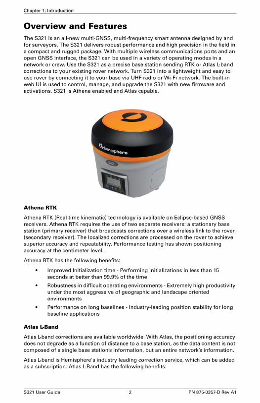
Overview and FeaturesThe S321 is an all-new multi-GNSS, multi-frequency smart antenna designed by and for surveyors. The S321 delivers robust performance and high precision in the field in a compact and rugged package. With multiple wireless communications ports and an open GNSS interface, the S321 can be used in a variety of operating modes in a network or crew. Use the S321 as a precise base station sending RTK or Atlas L-band corrections to your existing rover network. Turn S321 into a lightweight and easy to use rover by connecting it to your base via UHF radio or Wi-Fi network. The built-in web UI is used to control, manage, and upgrade the S321 with new firmware and activations. S321 is Athena enabled and Atlas capable.
Athena RTK
Athena RTK (Real time kinematic) technology is available on Eclipse-based GNSS receivers. Athena RTK requires the use of two separate receivers: a stationary base station (primary receiver) that broadcasts corrections over a wireless link to the rover (secondary receiver). The localized corrections are processed on the rover to achieve superior accuracy and repeatability. Performance testing has shown positioning accuracy at the centimeter level.
Athena RTK has the following benefits:
• Improved Initialization time - Performing initializations in less than 15 seconds at better than 99.9% of the time
• Robustness in difficult operating environments - Extremely high productivity under the most aggressive of geographic and landscape oriented environments
• Performance on long baselines - Industry-leading position stability for long baseline applications
Atlas L-Band
Atlas L-band corrections are available worldwide. With Atlas, the positioning accuracy does not degrade as a function of distance to a base station, as the data content is not composed of a single base station’s information, but an entire network’s information.
Atlas L-band is Hemisphere's industry leading correction service, which can be added as a subscription. Atlas L-Band has the following benefits:
S321 User Guide 2 PN 875-0357-D Rev A1

Chapter 1: Introduction
• Positioning accuracy - Competitive positioning accuracies down to 2 cm RMS in certain applications
• Positioning sustainability - Cutting edge position quality maintenance in the absence of correction signals, using Hemisphere’s patented technology
• Scalable service levels - Capable of providing virtually any accuracy, precision and repeatability level in the 2 to 100 cm range
• Convergence time - Industry-leading convergence times of 10-40 minutes
S321 is supported by our easy-to-use Atlas Portal (www.atlasgnss.com), which empowers you to update firmware and enable functionality, including Atlas subscriptions for accuracies from meter to sub-decimeter levels.
For more information about Athena RTK, see: http://hemispheregnss.com/Technology
For more information about Atlas L-band, see: http://hemispheregnss.com/Atlas
If your S321 is equipped with a 400 MHz radio you may be required to obtain a valid radio license for your jurisdiction.
aRTK Position Aiding
aRTK is an innovative feature available in Hemisphere’s S321 smart antenna that greatly mitigates the impact of land-based communication instability. Powered by Hemisphere’s Atlas L-Band system service, aRTK provides an additional layer of communication redundancy to RTK users, assuring that productivity is not impacted by intermittent data connectivity.
S321 receives the aRTK augmentation correction data over satellite, while also receiving the land-based RTK correction data. With this, the receiver internally operates with two sources of RTK correction, creating one additional layer of correction redundancy as compared to typical RTK systems. Once that process is established (which takes as less as a few seconds), the receiver is able to operate in the absence of either correction source, or in other words, and the receiver is able to continue generating RTK positions in case the land-based RTK correction source becomes unavailable for a period of time.
SureFix RTK Position
In order to provide high fidelity quality indicators to the users, Hemisphere created an additional processor that runs in combination with the RTK engine, called the SureFix processor. The SureFix processor takes several inputs, such as GNSS data, data preprocessing results, and generated RTK solutions. The SureFix processor takes all available information and, by using functional and stochastic analysis methods, it determines the quality of the current RTK engine solution. These are shown as “SufreFix quality indicators” in the diagram below. The SureFix indicators are then combined with the RTK solution before being provided to the user. At the end of the process, the user has access to high fidelity information about the quality of the RTK solution.
S321 User Guide 3 PN 875-0357-D Rev A1
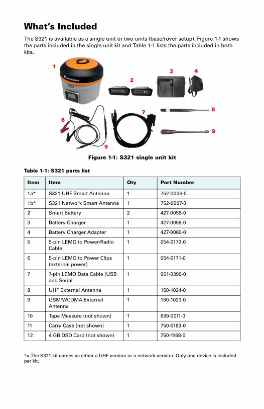
What’s IncludedThe S321 is available as a single unit or two units (base/rover setup). Figure 1-1 shows the parts included in the single unit kit and Table 1-1 lists the parts included in both kits.
Figure 1-1: S321 single unit kit
*= The S321 kit comes as either a UHF version or a network version. Only one device is included per kit.
Table 1-1: S321 parts list
Item Item Qty Part Number
1a* S321 UHF Smart Antenna 1 752-0006-0
1b* S321 Network Smart Antenna 1 752-0007-0
2 Smart Battery 2 427-0058-0
3 Battery Charger 1 427-0059-0
4 Battery Charger Adapter 1 427-0060-0
5 5-pin LEMO to Power/Radio Cable
1 054-0172-0
6 5-pin LEMO to Power Clips (external power)
1 054-0171-0
7 7-pin LEMO Data Cable (USB and Serial
1 051-0390-0
8 UHF External Antenna 1 150-1024-0
9 GSM/WCDMA External Antenna
1 150-1023-0
10 Tape Measure (not shown) 1 699-0011-0
11 Carry Case (not shown) 1 750-0183-0
12 4 GB DSD Card (not shown) 1 750-1168-0
1
2
3 4
5
67 8
9

Chapter 1: Introduction
S321 User Guide 5 PN 875-0357-D Rev A1

Chapter 2: InstallationPorts and Connections
Installing Batteries
Installing UHF and GSM Antenna
Installing on a Tribrach
Installing on a Range Pole
Connecting to a Power Source
Connecting to an External Device
Turning S321 On/Off
Inserting and Removing the SD and SIM Card
S321 User Guide 6 PN 875-0357-D Rev A1
Chapter 2: Installation
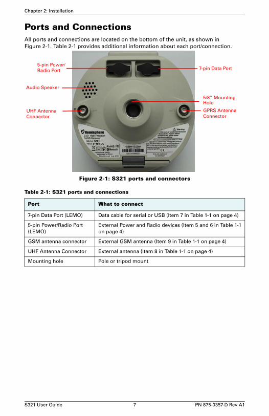
Ports and ConnectionsAll ports and connections are located on the bottom of the unit, as shown in Figure 2-1. Table 2-1 provides additional information about each port/connection.
Figure 2-1: S321 ports and connectors
Table 2-1: S321 ports and connections
Port What to connect
7-pin Data Port (LEMO) Data cable for serial or USB (Item 7 in Table 1-1 on page 4)
5-pin Power/Radio Port (LEMO)
External Power and Radio devices (Item 5 and 6 in Table 1-1 on page 4)
GSM antenna connector External GSM antenna (Item 9 in Table 1-1 on page 4)
UHF Antenna Connector External antenna (Item 8 in Table 1-1 on page 4)
Mounting hole Pole or tripod mount
GPRS Antenna
5-pin Power/
5/8” Mounting
7-pin Data Port
Audio Speaker
UHF Antenna Connector Connector
Hole
Radio Port
S321 User Guide 7 PN 875-0357-D Rev A1

Chapter 2: Installation
Installing/Connecting S321
Installing BatteriesThe S321 allows for one battery (11.1 V - 37.74 Wh) to be installed at a time. When installing the battery, ensure the contact points are facing up towards the “Hemisphere” logo. Slide the battery into the designated spot until the “battery tension bar” clicks into place. The projected run time of the battery is 6 hours, while running in UHF receive mode. The S321 kit provides two batteries, as noted in the “What’s Included?” portion of this user guide.
Figure 2-2: Battery installation
Battery Tension Bar
S321 User Guide 8 PN 875-0357-D Rev A1
Chapter 2: Installation
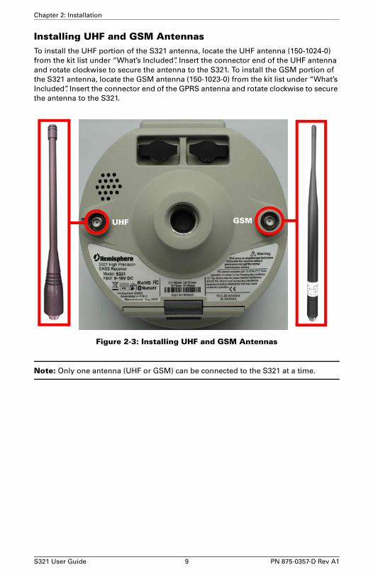
Installing UHF and GSM AntennasTo install the UHF portion of the S321 antenna, locate the UHF antenna (150-1024-0) from the kit list under “What’s Included”. Insert the connector end of the UHF antenna and rotate clockwise to secure the antenna to the S321. To install the GSM portion of the S321 antenna, locate the GSM antenna (150-1023-0) from the kit list under “What’s Included”. Insert the connector end of the GPRS antenna and rotate clockwise to secure the antenna to the S321.
Figure 2-3: Installing UHF and GSM Antennas
Note: Only one antenna (UHF or GSM) can be connected to the S321 at a time.
UHF GSM
S321 User Guide 9 PN 875-0357-D Rev A1
Chapter 2: Installation
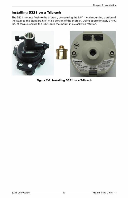
Installing S321 on a TribrachThe S321 mounts flush to the tribrach, by securing the 5/8” metal mounting portion of the S321 to the standard 5/8” male portion of the tribrach. Using approximately 3-4 ft./lbs. of torque, secure the S321 onto the mount in a clockwise rotation.
Figure 2-4: Installing S321 on a Tribrach
S321 User Guide 10 PN 875-0357-D Rev A1

Chapter 2: Installation
Vertical Extension for the Base
The vertical extension is a 25cm aluminum pole that mounts to the top of a tripod tribrach. This allows the S321 to have a similar height to the rover and also provides better access to the bottom of the S321 unit. Having more access to the bottom of the S321 makes for easier cable connections and adjustments to UHF or GPRS antennas.
Figure 2-5: Vertical base Extension
Installing the S321 on a Range Poleusing the standard 5/8” mount on the bottom of the S321, you can secure the unit to a field standard 5/8” range pole. the S321 should be placed carefully on the range pole, to ensure cross-threading does not occur, while rotating the unit in a clockwise direction. Apply approximately 3-4 ft./lbs. of torque to the unit.
Figure 2-6: Range Pole Installation
Vertical Extension
S321 User Guide 11 PN 875-0357-D Rev A1

Chapter 2: Installation
Connecting to a Power SourceThe S321 has two main power sources. The first being an internal, removable battery which is described in the earlier portion of this chapter. The second source of power is the external power cable (054-0171-0). The 5-pin (Lemo) connector allows 9 to 24V of power into the S321. Connecting external power maybe a reasonable solution when setting up a permanent base or setting a long term base in a remote area.
Figure 2-7: External Power Connector
5-pin Power Cable
S321 User Guide 12 PN 875-0357-D Rev A1

Chapter 2: Installation
Connecting to an External DeviceUsing the web UI to enable the S321 to receive outside communications, requires setting the S321 unit to “OEM” mode is the web UI. This can be accomplished by, selecting “Settings” in the top right portion of the web UI. Using your finger or mouse, locate the “Device Configuration” tab at the top of the “Settings” screen. Under the “Direct Link Mode” drop down list, select the “OEM” mode. After making the “OEM” selection, press the green “Save” button in the bottom of the “Settings” screen. Once saved, the S321 is ready to communicate over the 7-pin data port external DB9 or USB cable. The S321 has a standard baud rate of 115,200 when talking in OEM mode. Please make sure to set any interface or potential programs to 115,200 when talking to the S321. Directly connecting the external device to the S321 requires the use of the 7-pin (Lemo) data port, on the bottom of the unit. The external data cable (051-0390-0) allows you to connect via a DB9 serial connection.
Figure 2-8: External Device Connector
7-pin Data Cable
S321 User Guide 13 PN 875-0357-D Rev A1

Chapter 2: Installation
Using the on Device FN and I KeysThe on device menu can be navigated by using the on device keys. The FN key allows you to scroll through each item on the device menu display. The I key acts as an enter key for selecting to required menu option. The I key also acts as a power key when the menu option of “power” is selected. (See turning the S321 on/off below).
Turning the S321 On/OffIt has powers on/off the receiver function and has a confirm function.
• Power on receiver: Press I key for 1 second, the device will beep three times.
• Power off receiver: Press I key for 0.5 seconds in order to navigate to the main menu screen. Once on the main menu screen push the FN key to work the menu box to the I icon. When the box is located over the I icon, press the I key for 0.5 seconds to turn the device off.
Note: If you hold the I button for longer than 0.5 seconds, the device will go into self-check mode. (See “Self-Check” below for more information).
Self-Check: It is a procedure for verifying the correct working of the instrument devices. The program is mainly to predict whether the receiver modules works normal ahead of time or not. The self-checking includes status reviews of GPS, Wi-Fi, Bluetooth, radio, network and sensor, a total of six parts?
Note: The frequency setting of the internal UHF module is set back to factory default on self-test. Please contact your local dealer to obtain the frequency information in your country.
S321 User Guide 14 PN 875-0357-D Rev A1

Chapter 2: Installation
Removing/Inserting the Micro SD Card / SIM Card
Caution: Use electrostatic discharge (ESD) protection, such as by wearing an ESD strap that is attached to an earth ground, before inserting or removing the SIM card on the S321. If an ESD strap is not available then touch a metal object prior to accessing the SIM card holder.
The Micro SD card and the SIM card are only accessible by first opening the battery door, where the:
• The “SIM” card slot is positioned on the left side of the battery opening
• The “SD” card slot is positioned on the right side of the battery opening.
To remove the Micro SD card or SIM card:
1. Open the battery door.
2. Gently push the card in; it will then snap back and slightly out.
3. Remove the card.
Note: When you insert either card make sure the contacts on the card are facing upwards, towards the top of the unit and the side of the card with the notch goes in first.
To insert the Micro SD card or SIM card:
1. Place the card in its appropriate card slot.
2. Gently push the card in until it clicks.
3. Close and secure the battery door.
SIM CardCard
Micro SD
S321 User Guide 15 PN 875-0357-D Rev A1
Chapter 2: Installation
Micro SD Card Firmware UpdatePlace the upgrade files under “update” folder of the Micro SD card. Version info must be place after the file name and separated by “_”. The name must follow the naming convention listed below:
Receiver firmware:
S321_update_YYMMDD.bin
YY: Year
MM: Month
DD: Day
e.g. S321_update_160202.bin
OEM board firmware:
P306_OEM_XXXXX.bin
XXXXX: version
e.g. P306_OEM_5.2Aa3.bin
Radio firmware:
SATEL_update_XXXXX.bin
XXXXX: version
e.g. SATEL_update_V07.27.2.0.8.6.bin
3G module firmware:
PHS_update_XXXXX.bin
XXXXX: version
e.g. PHS_update_03.001.bin
Upgrading S321 Firmware via Serial PortUsing the web UI to enable the S321 to receive updated firmware for the GNSS board, requires setting the S321 unit to “OEM” mode. This can be accomplished by, selecting “Settings” in the top right portion of the web UI. Using your finger or mouse, locate the “Device Configuration” tab at the top of the “Settings” screen. Under the “Direct Link Mode” drop down list, select the “OEM” mode. After making the “OEM” selection, press the green “Save” button in the bottom of the “Settings” screen. Once saved, the S321 is ready to communicate over the 7-pin data port external DB9 or USB cable. The S321 has a standard baud rate of 115,200 when talking in OEM mode. Directly connecting the external device to the S321 requires the use of the 7-pin (Lemo) data port, on the bottom of the unit. The external data cable (051-0390-0) allows you to connect via a DB9 serial connection. Using Hemisphere’s standard RightArm and Autloader firmware tools, the device is ready to be updated. New versions of firmware can be found at www.hgnss.com, under the Resources & Support page.
S321 User Guide 16 PN 875-0357-D Rev A1
Chapter 2: Installation
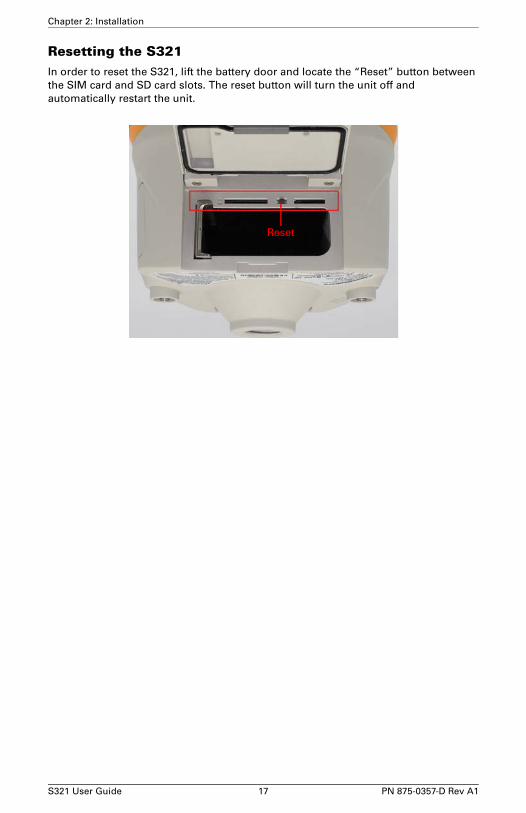
Resetting the S321In order to reset the S321, lift the battery door and locate the “Reset” button between the SIM card and SD card slots. The reset button will turn the unit off and automatically restart the unit.
Reset
S321 User Guide 17 PN 875-0357-D Rev A1

Chapter 2: Installation
S321 User Guide 18 PN 875-0357-D Rev A1

Chapter 3: Setup and ConfigurationControl Panel Overview
Connecting via Bluetooth
Connecting via Wi-Fi
Web UI Instructions
Setting-up the Unit
Base Setup
Rover Setup
Downloading Static Data
S321 User Guide 19 PN 875-0357-D Rev A1

Chapter 3: Setup and Configuration
Control Panel OverviewYou operate the S321 using the control panel shown below.
Figure 3-1: Control Panel and Display
Satellite LED (Green)The LED illuminates and stays a solid green color to indicate a signal/satellite lock has been achieved.
Figure 3-2: Satellite LED
Satellite LED
Power Button
Radio LED
GSM/WCDMA LED Wi-Fi LED
Bluetooth LED Static Logging LED
Function Button
S321 User Guide 20 PN 875-0357-D Rev A1

Chapter 3: Setup and Configuration
Static LED (Green)It switches on if the static mode is selected and it starts to blink when the receiver is recording data, with the same frequency of the sample rate.
Figure 3-3: Static LED
Bluetooth LED (Blue)Once you have connected the receiver with the data controller, this LED will illuminate.
Figure 3-4: Bluetooth LED
S321 User Guide 21 PN 875-0357-D Rev A1

Chapter 3: Setup and Configuration
Wi-Fi LED (Green)This is indicates the S321 is emitting a Wi-Fi network and is ready to be paired with a Wi-Fi enabled controller or device. By connecting to the S321 device network, you are able to control the S321 via web UI. For more information on the web UI, please see page 22
Figure 3-5: Wi-Fi LED
External Data Link or Internal UHF Radio LED (Green)The LED is green when the device is selected as an RTK data link, via an external data link or an internal UHF radio link. It begins blinking when the S321 is either transmitting data as a base, or receiving data as a rover.
Figure 3-6: Internal UHF Radio LED
S321 User Guide 22 PN 875-0357-D Rev A1

Chapter 3: Setup and Configuration
Network LED (Green)The light is on when the network module is selected as RTK data link. It starts to blink when receiving and transmitting data. (Download in rover mode and upload in base mode)
Figure 3-7: Network LED
PowerIncludes t modes of function:
1. LED Display On: Power supply is functioning at full capacity
2. Blinking LEDs and Beeping: Very low power (below 10%)
When the power is below 10%, the LEDs will flash according to sample interval (default is 1 second) and you also hear three beeps every 60 seconds.
S321 User Guide 23 PN 875-0357-D Rev A1
Chapter 3: Setup and Configuration
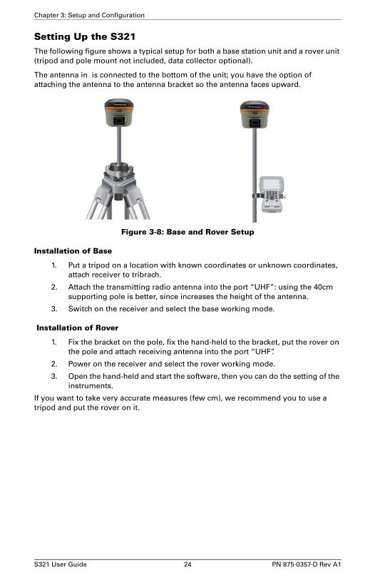
Setting Up the S321The following figure shows a typical setup for both a base station unit and a rover unit (tripod and pole mount not included, data collector optional).
The antenna in is connected to the bottom of the unit; you have the option of attaching the antenna to the antenna bracket so the antenna faces upward.
Figure 3-8: Base and Rover Setup
Installation of Base
1. Put a tripod on a location with known coordinates or unknown coordinates, attach receiver to tribrach.
2. Attach the transmitting radio antenna into the port “UHF”: using the 40cm supporting pole is better, since increases the height of the antenna.
3. Switch on the receiver and select the base working mode.
Installation of Rover
1. Fix the bracket on the pole, fix the hand-held to the bracket, put the rover on the pole and attach receiving antenna into the port “UHF”.
2. Power on the receiver and select the rover working mode.
3. Open the hand-held and start the software, then you can do the setting of the instruments.
If you want to take very accurate measures (few cm), we recommend you to use a tripod and put the rover on it.
S321 User Guide 24 PN 875-0357-D Rev A1
Chapter 3: Setup and Configuration
Bluetooth CommunicationIf you have a Bluetooth-enabled device, such as a data collector, you can wirelessly communicate with the S321.
When you attempt to connect the S321 to a Bluetooth-enabled device, such as a hand-held data collector, the following S321 Bluetooth information appears on the device:
S321 XXXXXX
where “XXXXXX” is the serial number
To complete the connection you must use the correct PIN/Passkey, which is 1234.
S321 User Guide 25 PN 875-0357-D Rev A1
Chapter 3: Setup and Configuration
Hemisphere Web UIThe web UI can work on any PC, Tablet, or Phone that has Wi-Fi network capabilities.
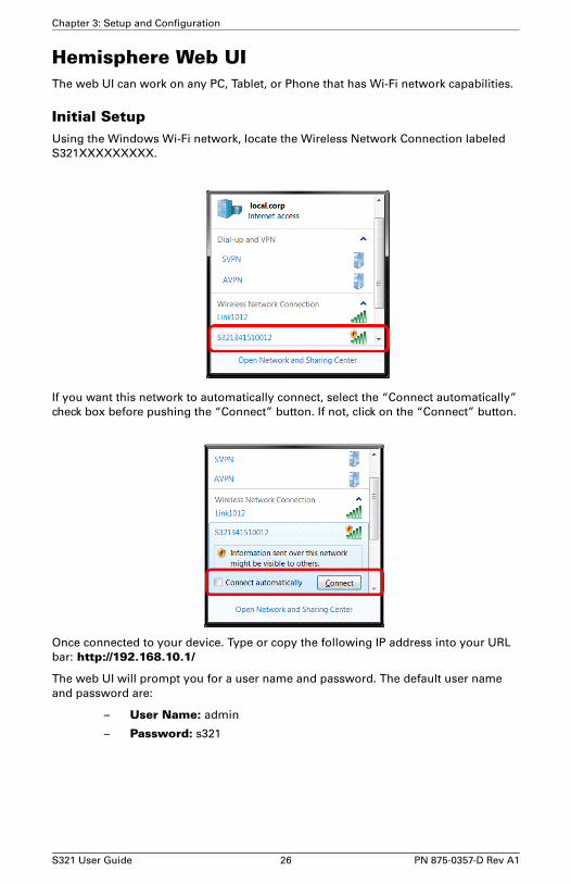
Initial SetupUsing the Windows Wi-Fi network, locate the Wireless Network Connection labeled S321XXXXXXXXX.
If you want this network to automatically connect, select the “Connect automatically” check box before pushing the “Connect” button. If not, click on the “Connect” button.
Once connected to your device. Type or copy the following IP address into your URL bar: http://192.168.10.1/
The web UI will prompt you for a user name and password. The default user name and password are:
– User Name: admin
– Password: s321
S321 User Guide 26 PN 875-0357-D Rev A1

Chapter 3: Setup and Configuration
Web UI StartupThe “Status” tab, provides general GNSS information including System mode, Latitude, Longitude, and Height.
S321 User Guide 27 PN 875-0357-D Rev A1

Chapter 3: Setup and Configuration
The “Information” tab, contains device and module information, in addition to current software and firmware versions.
S321 User Guide 28 PN 875-0357-D Rev A1

Chapter 3: Setup and Configuration
The “Download” tab, allows you to log and review multiple data files from the on-board memory of the device.
The “Management” tab, provides access to the firmware update tools, a terminal to register authorization codes, and password customization in order to properly secure your device moving forward.
Install New Firmware:
This feature allows you to update the menu application software. Once the correct software is selected under the “choose file” browser, the “Upload” button initiates the update procedure and restarts the S321 device.
Registration:
This displays the expiration date of different features which have been subscribed to the S321. More specifically, if the S321 has been activated for Atlas, the appropriate
S321 User Guide 29 PN 875-0357-D Rev A1

Chapter 3: Setup and Configuration
Atlas expiration date will be displayed under this field. In addition, the ability to update the S321 with new subscriptions is available under the “AuthCode” field. Enter the new Atlas code and the device will automatically update.
Security:
The security field allows the user to enable or disable login requirements. The user is able to reset or customize a new password for their device. By filling in the required fields to change the password, Old Password, New Password and Confirm Password.
View Logs:
The view logs field allows you to track any activity at the application and OS level. This is important when troubleshooting any issues.
Formatting / Self Test / Reset:
The Format internal disk button allow you to reformat the internal hard drive in the S321. Self test, provides an application review to ensure the device functioning properly (See self-check for more information). Reset, initiates a complete device shut down. Creating a hard reset to the device and stopping any application activity. (See resetting the S321 for more information).
S321 User Guide 30 PN 875-0357-D Rev A1

Chapter 3: Setup and Configuration
Web UI SettingsWorking Modes:
Base/UHF
Tip: When using a UHF datalink, selecting “Channel 8” allows you to manually input the radio frequency. This option is available below under “Radio Channel”..
S321 User Guide 31 PN 875-0357-D Rev A1
Chapter 3: Setup and Configuration
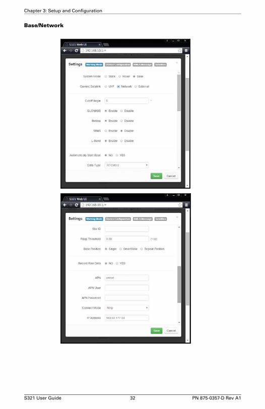
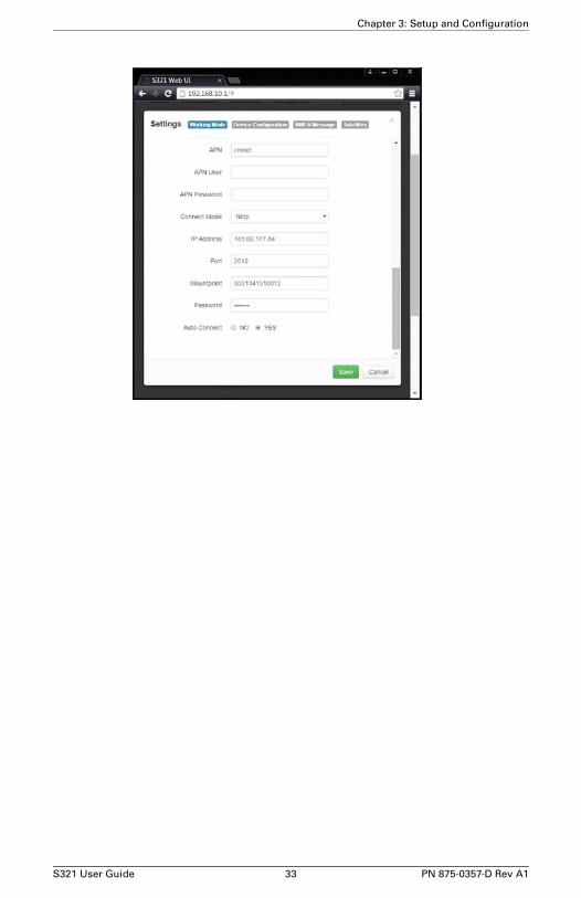
Base/Network
S321 User Guide 32 PN 875-0357-D Rev A1
Chapter 3: Setup and Configuration
S321 User Guide 33 PN 875-0357-D Rev A1

Chapter 3: Setup and Configuration
Base/External
S321 User Guide 34 PN 875-0357-D Rev A1

Chapter 3: Setup and Configuration
Rover/UHF
Tip: When using a UHF datalink, selecting “Channel 8” allows you to manually input the radio frequency. This option is available below under “Radio Channel”
S321 User Guide 35 PN 875-0357-D Rev A1

Chapter 3: Setup and Configuration
Rover/Network
S321 User Guide 36 PN 875-0357-D Rev A1

Chapter 3: Setup and Configuration
S321 User Guide 37 PN 875-0357-D Rev A1
Chapter 3: Setup and Configuration
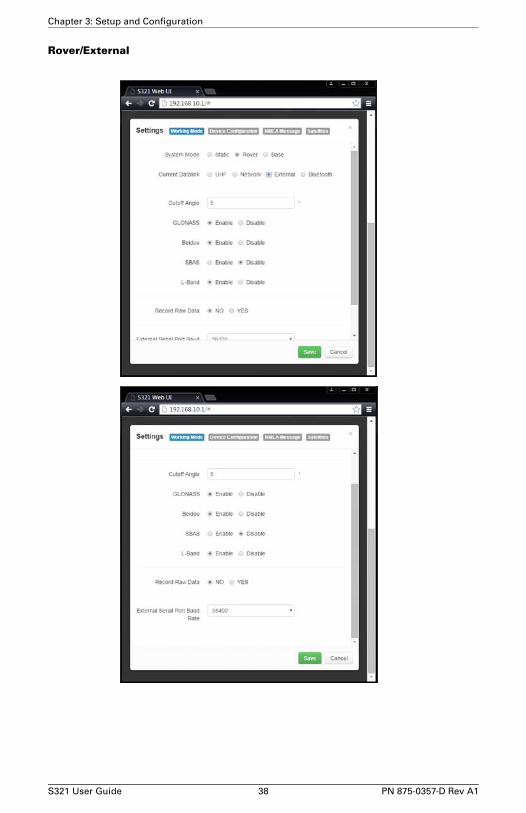
Rover/External
S321 User Guide 38 PN 875-0357-D Rev A1

Chapter 3: Setup and Configuration
Rover/Bluetooth
S321 User Guide 39 PN 875-0357-D Rev A1

Chapter 3: Setup and Configuration
Static
S321 User Guide 40 PN 875-0357-D Rev A1

Chapter 3: Setup and Configuration
Device ConfigurationThe device configuration tab allows for custom settings in terms of language, time zones, storage, and a number of other options.
When enabling the speaker, the S321 relays the status of the positioning via voice updates. Specifically, the S321 will audibly indicate when the receiver is in Base or Rover mode. Voice indication covers, logging data, and declaring when the S321 has achieved RTK float and RTK fix. This is important when working in a low visibility environment.
Some of the most important portions of the device configuration is the ability to select your Direct Link Mode, giving you the option to connect via external serial devices (OEM), radio (UHF), and TTS. In addition, the easy to use radio buttons allow you to use tracker, remote debug, and select which mode of data logging storage you wish to use, SD or Internal.
S321 User Guide 41 PN 875-0357-D Rev A1
Chapter 3: Setup and Configuration
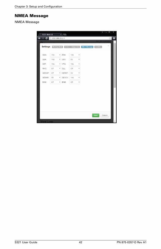
NMEA MessageNMEA Message
S321 User Guide 42 PN 875-0357-D Rev A1

Chapter 3: Setup and Configuration
Satellites
Satellites
S321 User Guide 43 PN 875-0357-D Rev A1

Chapter 3: Setup and Configuration
S321 User Guide 44 PN 875-0357-D Rev A1

Chapter 3: Setup and Configuration
GSM / NTRIP FunctionalityThis section provides advanced GSM information that requires connecting to the web UI. Using the web UI, press the “Settings” button in the top right portion of the screen. Then navigate to the “Working Mode” tab and select the “Network” radio button to put the device in Network mode. By selecting the Network button, the screen has been altered to accept GSM or NTRIP information. See Base/Network or Rover/Network in the web UI walk-through above.
This section covers the following topics:
• GSM overview
• GSM modes
• Configuring GSM for NTRIP
• Configuring GSM for TCP/IP
GSM OverviewGlobal System for Mobile Communications (GSM) is a network technology for mobile phone communications. The GSM modem in the S321 is what allows you to connect to a GSM carrier.
The Access Point Name (APN) is a protocol that allows the S321 to access the internet using the mobile phone network. It is a configurable network identifier used when connecting to a GSM carrier. The specific APN required by the S321 depends on your mobile carrier. Check with your mobile provider for details.
GSM ModesThe GSM module operates in four modes:
• NTRIP - Used to provide differential correction information to the GNSS receiver.
• TCP/IP - For users to establish a link between two S321 modules directly, where the BASE has a dynamic IP address. You should only use this mode on the rover in a base station / rover setup.
• The dynamic IP address is available when TCP/IP is selected under the base configuration. Allowing the cell modem to reach the secondary device and report the IP address.
Configuring GSM for NTRIPNTRIP (Networked Transport of RTCM via Internet Protocol) is the protocol for transmitting GNSS data over the internet.
Note: To configure NTRIP you must connect the S321 via Wi-Fi to the web UI.
To configure NTRIP fill in the following fields under the “Network” screen in the web UI. For instructions to access the web UI see page 23.
S321 User Guide 45 PN 875-0357-D Rev A1

Chapter 3: Setup and Configuration
Base/Network (NTRIP)
• APN User name and password - authentication with a user name and password is required for most NTRIP casters. You can leave both blank to specify that no authentication is required. The user name and password are case sensitive.
• Mount point - caster stream name from NTRIP Caster Source Table. If you leave this field blank, the S321 will fetch the caster source table and select the mount point closest to its current position.
S321 User Guide 46 PN 875-0357-D Rev A1

Chapter 3: Setup and Configuration
Rover/Network (NTRIP)
• APN User name and password - authentication with a user name and password is required for most NTRIP casters. You can leave both blank to specify that no authentication is required. The user name and password are case sensitive.
• Mount point - Select “Get Mountpoint” button and the correct mountpoint will be delivered from the base.
• User and Password - Required before for talking to the selected mountpoint.
S321 User Guide 47 PN 875-0357-D Rev A1

Chapter 3: Setup and Configuration
Base/Network (TCP/IP)
• APN User name and password - authentication with a user name and password is required for most network based work. You can leave both blank to specify that no authentication is required. The user name and password are case sensitive..
S321 User Guide 48 PN 875-0357-D Rev A1
Chapter 3: Setup and Configuration
Rover/Network (TCP/IP)
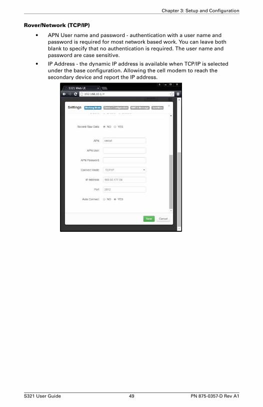
• APN User name and password - authentication with a user name and password is required for most network based work. You can leave both blank to specify that no authentication is required. The user name and password are case sensitive.
• IP Address - the dynamic IP address is available when TCP/IP is selected under the base configuration. Allowing the cell modem to reach the secondary device and report the IP address.
S321 User Guide 49 PN 875-0357-D Rev A1

Chapter 3: Setup and Configuration
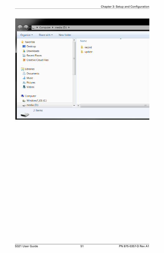
How to download Static DataYou can download static data by web UI “Download” tab and by USB. For a correct connection between receiver and PC, follow the procedure described below.
At first turn off the receiver, then connect the cable to the communication interface of the receiver (7-pin Lemo) port, then insert the USB port in the PC. Turn the S321 back on and the following task-bar will show as follows:
The PC considers the receiver as a “media disk”, so open the “media disk”, and then you can get the data files in the memory.
S321 User Guide 50 PN 875-0357-D Rev A1
Chapter 3: Setup and Configuration
S321 User Guide 51 PN 875-0357-D Rev A1

Chapter 3: Setup and Configuration
S321 User Guide 52 PN 875-0357-D Rev A1
Appendix A: Troubleshooting
S321 User Guide 53 PN 875-0357-D Rev A1
Appendix A: Troubleshooting
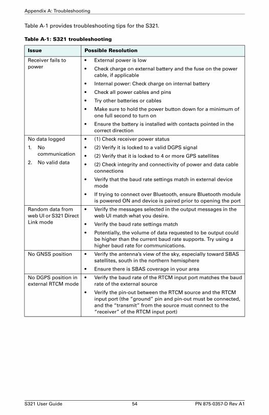
Table A-1 provides troubleshooting tips for the S321.
Table A-1: S321 troubleshooting
Issue Possible Resolution
Receiver fails to power
• External power is low
• Check charge on external battery and the fuse on the power cable, if applicable
• Internal power: Check charge on internal battery
• Check all power cables and pins
• Try other batteries or cables
• Make sure to hold the power button down for a minimum of one full second to turn on
• Ensure the battery is installed with contacts pointed in the correct direction
No data logged
1. No communication
2. No valid data
• (1) Check receiver power status
• (2) Verify it is locked to a valid DGPS signal
• (2) Verify that it is locked to 4 or more GPS satellites
• (2) Check integrity and connectivity of power and data cable connections
• Verify that the baud rate settings match in external device mode
• If trying to connect over Bluetooth, ensure Bluetooth module is powered ON and device is paired prior to opening the port
Random data from web UI or S321 Direct Link mode
• Verify the messages selected in the output messages in the web UI match what you desire.
• Verify the baud rate settings match
• Potentially, the volume of data requested to be output could be higher than the current baud rate supports. Try using a higher baud rate for communications.
No GNSS position • Verify the antenna’s view of the sky, especially toward SBAS satellites, south in the northern hemisphere
• Ensure there is SBAS coverage in your area
No DGPS position in external RTCM mode
• Verify the baud rate of the RTCM input port matches the baud rate of the external source
• Verify the pin-out between the RTCM source and the RTCM input port (the “ground” pin and pin-out must be connected, and the “transmit” from the source must connect to the “receiver” of the RTCM input port)
S321 User Guide 54 PN 875-0357-D Rev A1

Appendix B: Technical Specifications
S321 User Guide 55 PN 875-0357-D Rev A1

Appendix B: Technical Specifications
The following tables provide information on the technical specifications of the S321.
Table B-1: GNSS receiver specifications
Item Specification
Receiver type Multi Frequency GNSS
Channels 372
Positioning modes RTK, L-band DGNSS, SBAS, External RTCM, Autonomous
RTK formats RTCM3.0, CMR, CMR+, ROX
L-band formats Atlas H100, Atlas H30, and Atlas H10
Update rate / recording interval Selectable from 1, 2, 4, 5, 10, 20 Hz
Table B-2: Performance Specifications
Mode Specification
Horizontal Vertical
RTK
Performance
8mm + 1 ppm 15mm + 1 ppm
Static
Performance
(long occupation)
3mm + 0.1 ppm 3.5mm + 0.4 ppm
Static
Performance (rapid occupation)
3mm + 0.5 ppm 5mm + 0.5 ppm
L-band
Performance3
0.08 m 0.16m
SBAS
Performance1
0.3 m 0.6 m
Autonomous, no
SA2
1.2 m 2.4 m
Table B-3: Satellite Tracking
Satellites
GPS L1C/A, L1P, L2P, L2C
GLONASS L1C/A, L2C/A
BeiDou B1, B2
QZSS With future firmware upgrade
Galileo With future firmware upgrade
S321 User Guide 56 PN 875-0357-D Rev A1
Appendix B: Technical Specifications
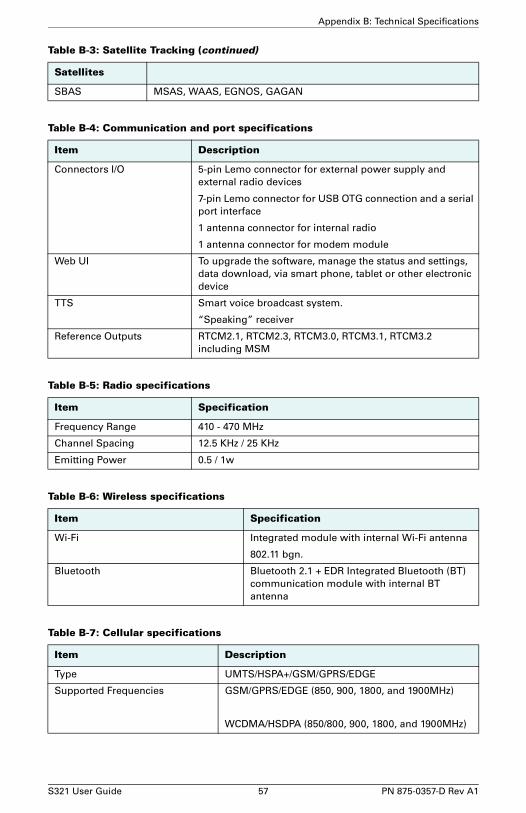
SBAS MSAS, WAAS, EGNOS, GAGAN
Table B-4: Communication and port specifications
Item Description
Connectors I/O 5-pin Lemo connector for external power supply and external radio devices
7-pin Lemo connector for USB OTG connection and a serial port interface
1 antenna connector for internal radio
1 antenna connector for modem module
Web UI To upgrade the software, manage the status and settings, data download, via smart phone, tablet or other electronic device
TTS Smart voice broadcast system.
“Speaking” receiver
Reference Outputs RTCM2.1, RTCM2.3, RTCM3.0, RTCM3.1, RTCM3.2 including MSM
Table B-5: Radio specifications
Item Specification
Frequency Range 410 - 470 MHz
Channel Spacing 12.5 KHz / 25 KHz
Emitting Power 0.5 / 1w
Table B-6: Wireless specifications
Item Specification
Wi-Fi Integrated module with internal Wi-Fi antenna
802.11 bgn.
Bluetooth Bluetooth 2.1 + EDR Integrated Bluetooth (BT) communication module with internal BT antenna
Table B-7: Cellular specifications
Item Description
Type UMTS/HSPA+/GSM/GPRS/EDGE
Supported Frequencies GSM/GPRS/EDGE (850, 900, 1800, and 1900MHz)
WCDMA/HSDPA (850/800, 900, 1800, and 1900MHz)
Table B-3: Satellite Tracking (continued)
Satellites
S321 User Guide 57 PN 875-0357-D Rev A1

1 Depends on multi-path environment, number of satellites in view, satellite geometry, and ionospheric activity
Table B-8: Power specifications
Item Specification
Battery Rechargeable 11.1 V - 37.74 Wh
Battery Life 6 hours with one battery and UHF radio in Rx mode
Voltage 9 to 22V DC external power input with over-voltage protection
Charge Time Typically 7 hours
Table B-9: Memory specifications
item Specification
SIM Card Accessible SIM card slot
Memory Internal 4GB. Accessible through USB and Wi-Fi
External Micro SD card slot supports up to 64 GB.
Table B-10: Environmental specifications
Item Specification
Operating Temperature -30°C to 60°C (-22°F to 140°F)
Storage Temperature -40°C to 80°C (-22°F to 176°F)
Water / Dust Proof IP67
Shock Resistance MIL-STD-810G, method 516.6
Vibration MIL-STD-810G, method 514.6E-I
Humidity Up to 100%
Table B-11: Mechanical specifications
Item Specification
Size 14.1 D x 14.0 H (cm)
5.5 D x 5.5 H (in)
Weight <1.38 kg (<3.05 lbs
Mounting 5/8”x11, 55 ° thread angle, stainless steel insert
Phase Center Offset GPS L1 and L2 offset below 2.5mm

Appendix B: Technical Specifications
2 Depends also on baseline length
3 Requires a subscription from Hemisphere GNSS
S321 User Guide 59 PN 875-0357-D Rev A1

Warranty NoticeCOVERED PRODUCTS: This warranty covers all products manufactured by Hemisphere GNSS and purchased by the end purchaser (the "Products"), unless otherwise specifically and expressly agreed in writing by Hemisphere GNSS.
LIMITED WARRANTY: Hemisphere GNSS warrants solely to the end purchaser of the Products, subject to the exclusions and procedures set forth below, that the Products sold to such end purchaser and its internal components shall be free, under normal use and maintenance, from defects in materials, and workmanship and will substantially conform to Hemisphere GNSS’s applicable specifications for the Product, for a period of 12 months from delivery of such Product to such end purchaser (the ”Warranty Period”). Repairs and replacement components for the Products are warranted, subject to the exclusions and procedures set forth below, to be free, under normal use and maintenance, from defects in material and workmanship, and will substantially conform to Hemisphere GNSS’s applicable specifications for the Product, for 90 days from performance or delivery, or for the balance of the original Warranty Period, whichever is greater.
EXCLUSION OF ALL OTHER WARRANTIES. The LIMITED WARRANTY shall apply only if the Product is properly and correctly installed, configured, interfaced, maintained, stored, and operated in accordance with Hemisphere GNSS’s relevant User’s Manual and Specifications, AND the Product is not modified or misused. The Product is provided “AS IS” and the implied warranties of MERCHANTABILITY and FITNESS FOR A PARTICULAR PURPOSE and ALL OTHER WARRANTIES, express, implied or arising by statute, by course of dealing or by trade usage, in connection with the design, sale, installation, service or use of any products or any component thereof, are EXCLUDED from this transaction and shall not apply to the Product. The LIMITED WARRANTY is IN LIEU OF any other warranty, express or implied, including but not limited to, any warranty of MERCHANTABILITY or FITNESS FOR A PARTICULAR PURPOSE, title, and non-infringement.
LIMITATION OF REMEDIES. The purchaser’s EXCLUSIVE REMEDY against Hemisphere GNSS shall be, at Hemisphere GNSS’s option, the repair or replacement of any defective Product or components thereof. The purchaser shall notify Hemisphere GNSS or a Hemisphere GNSS’s approved service center immediately of any defect. Repairs shall be made through a Hemisphere GNSS approved service center only. Repair, modification or service of Hemisphere GNSS products by any party other than a Hemisphere GNSS approved service center shall render this warranty null and void. The remedy in this paragraph shall only be applied in the event that the Product is properly and correctly installed, configured, interfaced, maintained, stored, and operated in accordance with Hemisphere GNSS’s relevant User’s Manual and Specifications, AND the Product is not modified or misused. NO OTHER REMEDY (INCLUDING, BUT NOT LIMITED TO, SPECIAL, INDIRECT, INCIDENTAL, CONSEQUENTIAL OR CONTINGENT DAMAGES FOR LOST PROFITS, LOST SALES, INJURY TO PERSON OR PROPERTY, OR ANY OTHER INCIDENTAL OR CONSEQUENTIAL LOSS) SHALL BE AVAILABLE TO PURCHASER, even if Hemisphere GNSS has been advised of the possibility of such damages. Without limiting the foregoing, Hemisphere GNSS shall not be liable for any damages of any kind resulting from installation, use, quality, performance or accuracy of any Product.
HEMISPHERE IS NOT RESPONSIBLE FOR PURCHASER’S NEGLIGENCE OR UNAUTHORIZED USES OF THE PRODUCT. IN NO EVENT SHALL Hemisphere GNSS BE IN ANY WAY RESPONSIBLE FOR ANY DAMAGES RESULTING FROM PURCHASER’S OWN NEGLIGENCE, OR FROM OPERATION OF THE PRODUCT IN ANY WAY OTHER THAN AS SPECIFIED IN Hemisphere GNSS’S RELEVANT USER’S MANUAL AND SPECIFICATIONS. Hemisphere GNSS is NOT RESPONSIBLE for defects or performance problems resulting from (1) misuse, abuse, improper installation, neglect of Product; (2) the utilization of the Product with hardware or software products, information, data, systems, interfaces or devices not made, supplied or specified by Hemisphere GNSS; (3) the operation of the Product under any specification other than, or in addition to, the specifications set forth in Hemisphere GNSS’s relevant User’s Manual and Specifications; (4) damage caused by accident or natural events, such as lightning (or other electrical discharge) or fresh/salt water immersion of Product; (5) damage occurring in transit; (6) normal wear and tear; or (7) the operation or failure of operation of any satellite-based positioning system or differential correction service; or the availability or performance of any satellite-based positioning signal or differential correction signal.
THE PURCHASER IS RESPONSIBLE FOR OPERATING THE VEHICLE SAFELY. The purchaser is solely responsible for the safe operation of the vehicle used in connection with the Product, and for maintaining proper system control settings. UNSAFE DRIVING OR SYSTEM CONTROL SETTINGS CAN RESULT IN PROPERTY DAMAGE, INJURY, OR DEATH. The purchaser is solely responsible for his/her safety and for the safety of others. The purchaser is solely responsible for maintaining control of the automated steering system at all times. THE PURCHASER IS SOLELY RESPONSIBLE FOR ENSURING THE PRODUCT IS PROPERLY AND CORRECTLY INSTALLED, CONFIGURED, INTERFACED, MAINTAINED, STORED, AND OPERATED IN ACCORDANCE WITH Hemisphere GNSS’S RELEVANT USER’S MANUAL AND SPECIFICATIONS. Hemisphere GNSS does not warrant or guarantee the positioning and navigation precision or accuracy obtained when using Products. Products are not intended for primary navigation or for use in safety of life applications. The potential accuracy of Products as stated in Hemisphere GNSS literature and/or Product specifications serves to provide only an estimate of achievable accuracy based on performance specifications provided by the satellite service operator (i.e. US Department of Defense in the case of GPS) and differential correction service provider. Hemisphere GNSS reserves the right to modify Products without any obligation to notify, supply or install any improvements or alterations to existing Products.
GOVERNING LAW. This agreement and any disputes relating to, concerning or based upon the Product shall be governed by and interpreted in accordance with the laws of the State of Arizona.
OBTAINING WARRANTY SERVICE. In order to obtain warranty service, the end purchaser must bring the Product to a Hemisphere GNSS approved service center along with the end purchaser's proof of purchase. Hemisphere GNSS does not warrant claims asserted after the end of the warranty period. For any questions regarding warranty service or to obtain information regarding the location of any of Hemisphere GNSS approved service center, contact Hemisphere GNSS at the following address:
Hemisphere GNSS8515 E. Anderson DriveScottsdale, AZ 85255Phone: 480-348-6380 Fax: [email protected]

End User License AgreementIMPORTANT - This is an agreement (the "Agreement") between you, the end purchaser ("Licensee") and Hemisphere GNSS Inc. ("Hemisphere") which permits Licensee to use the Hemisphere software (the "Software") that accompanies this Agreement. This Software may be licensed on a standalone basis or may be embedded in a Product. Please read and ensure that you understand this Agreement before installing or using the Software Update or using a Product.
In this agreement any product that has Software embedded in it at the time of sale to the Licensee shall be referred to as a "Product". As well, in this Agreement, the use of a Product shall be deemed to be use of the Software which is embedded in the Product.
BY INSTALLING OR USING THE SOFTWARE UPDATE OR THE PRODUCT, LICENSEE THEREBY AGREES TO BE LEGALLY BOUND BY THE TERMS OF THIS AGREEMENT. IF YOU DO NOT AGREE TO THESE TERMS, (I) DO NOT INSTALL OR USE THE SOFTWARE, AND (II) IF YOU ARE INSTALLING AN UPDATE TO THE SOFTWARE, DO NOT INSTALL THE UPDATE AND PROMPTLY DESTROY IT.
HEMISPHERE PROVIDES LIMITED WARRANTIES IN RELATION TO THE SOFTWARE. AS WELL, THOSE WHO USE THE EMBEDDED SOFTWARE DO SO AT THEIR OWN RISK. YOU SHOULD UNDERSTAND THE IMPORTANCE OF THESE AND OTHER LIMITATIONS SET OUT IN THIS AGREEMENT BEFORE INSTALLING OR USING THE SOFTWARE OR THE PRODUCT.
1. LICENSE. Hemisphere hereby grants to Licensee a non-transferable and non-exclusive license to use the Software as embedded in a Product and all Updates (collectively the "Software"), solely in binary executable form.
2. RESTRICTIONS ON USE. Licensee agrees that Licensee and its employees will not directly or indirectly, in any manner whatsoever:
a. install or use more copies of the Software than the number of copies that have been licensed;
b. use or install the Software in connection with any product other than the Product the Software was intended to be used or installed on as set out in the documentation that accompanies the Software.
c. copy any of the Software or any written materials for any purpose except as part of Licensee's normal backup processes;
d. modify or create derivative works based on the Software;
e. sub-license, rent, lease, loan or distribute the Software;
f. permit any third party to use the Software;
g. use or operate Product for the benefit of any third party in any type of service outsourcing, application service, provider service or service bureau capacity;
h. reverse engineer, decompile or disassemble the Software or otherwise reduce it to a human perceivable form;
i. Assign this Agreement or sell or otherwise transfer the Software to any other party except as part of the sale or transfer of the whole Product.
3. UPDATES. At Hemisphere's discretion Hemisphere may make Updates available to Licensee. An update ("Update") means any update to the Software that is made available to Licensee including error corrections, enhancements and other modifications. Licensee may access, download and install Updates during the Warranty Period only. All Updates that Licensee downloads, installs or uses shall be deemed to be Software and subject to this Agreement. Hemisphere reserves the right to modify the Product without any obligation to notify, supply or install any improvements or alterations to existing Software.
4. SUPPORT. Hemisphere may make available directly or through its authorized dealers telephone and email support for the Software. Contact Hemisphere to find the authorized dealer near you. As well, Hemisphere may make available user and technical documentation regarding the Software. Hemisphere reserves the right to reduce and limit access to such support at any time.
5. BACKUPS AND RECOVERY. Licensee shall back-up all data used, created or stored by the Software on a regular basis as necessary to enable proper recovery of the data and related systems and processes in the event of a malfunction in the Software or any loss or corruption of data caused by the Software. Licensee shall assume all risks of loss or damage for any failure to comply with the foregoing.
6. OWNERSHIP. Hemisphere and its suppliers own all rights, title and interest in and to the Software and related materials, including all intellectual property rights. The Software is licensed to Licensee, not sold.
7. TRADEMARKS. "Hemisphere GNSS", "Outback Guidance", "BEELINE", "Crescent", "Eclipse" and the associated logos are trademarks of Hemisphere. Other trademarks are the property of their respective owners. Licensee may not use any of these trademarks without the consent of their respective owners.
8. LIMITED WARRANTY. Hemisphere warrants solely to the Licensee, subject to the exclusions and procedures set forth herein below, that for a period of one (1) year from the original date of purchase of the Product in which it is embedded (the "Warranty Period"), the Software, under normal use and maintenance, will conform in all material respects to the documentation provided with the Software and any media will be free of defects in materials and workmanship. For any Update, Hemisphere warrants, for 90 days from performance or delivery, or for the balance of the original Warranty Period, whichever is greater, that the Update, under normal use and maintenance, will conform in all material respects to the documentation provided with the Update and any media will be free of defects in materials and workmanship. Notwithstanding the foregoing, Hemisphere does not warrant that the Software will meet Licensee's requirements or that its operation will be error free.
9. WARRANTY EXCLUSIONS. The warranty set forth in Section (8) will not apply to any deficiencies caused by (a) the Product not being used as described in the documentation supplied to Licensee, (b) the Software having been altered, modified or converted in any way by anyone other than Hemisphere approved by Hemisphere, (c) any malfunction of Licensee's equipment or other software, or (d) damage occurring in transit or due to any accident, abuse, misuse, improper installation, lightning (or other electrical discharge) or neglect other than that caused by Hemisphere. Hemisphere GNSS does not warrant or guarantee the precision or accuracy of positions obtained when using the Software (whether standalone or embedded in a Product). The Product and the Software is not intended and should not be used as the primary means of navigation or for use in safety of life applications. The
potential positioning and navigation accuracy obtainable with the Software as stated in the Product or Software documentation serves to provide only an estimate of achievable accuracy based on specifications provided by the US Department of Defense for GPS positioning and DGPS service provider performance specifications, where applicable.
10. WARRANTY DISCLAIMER. EXCEPT AS EXPRESSLY SET OUT IN THIS AGREEMENT, HEMISPHERE MAKES NO REPRESENTATION, WARRANTY OR CONDITION OF ANY KIND TO LICENSEE, WHETHER VERBAL OR WRITTEN AND HEREBY DISCLAIMS ALL REPRESENTATIONS, WARRANTIES AND CONDITIONS OF ANY KIND INCLUDING FITNESS FOR A PARTICULAR PURPOSE, MERCHANTABILITY, ACCURACY, RELIABILITY OR THAT THE USE OF THE SOFTWARE WILL BE UNINTERRUPTED OR ERROR-FREE AND HEREBY DISCLAIMS ALL REPRESENTATIONS, WARRANTIES AND CONDITIONS ARISING AS A RESULT OF CUSTOM, USAGE OR TRADE AND THOSE ARISING UNDER STATUTE.
11. LIMITS ON WARRANTY DISCLAIMER. Some jurisdictions do not allow the exclusion of implied warranties or conditions, so some of the above exclusions may not apply to Licensee. In that case, any implied warranties or conditions which would then otherwise arise will be limited in duration to ninety (90) days from the date of the license of the Software or the purchase of the Product. The warranties given herein give Licensee specific legal rights and Licensee may have other rights which may vary from jurisdiction to jurisdiction.
12. CHANGE TO WARRANTY. No employee or agent of Hemisphere is authorized to change the warranty provided or the limitation or disclaimer of warranty provisions. All such changes will only be effective if pursuant to a separate agreement signed by senior officers of the respective parties.
13. WARRANTY CLAIM. In the event Licensee has a warranty claim Licensee must first check for and install all Updates that are made available. The warranty will not otherwise be honored. Proof of purchase may be required. Hemisphere does not honor claims asserted after the end of the Warranty Period.
14. LICENSEE REMEDIES. In all cases which involve a failure of the Software to conform in any material respect to the documentation during the Warranty Period or a breach of a warranty, Hemisphere's sole obligation and liability, and Licensee's sole and exclusive remedy, is for Hemisphere, at Hemisphere's option, to (a) repair the Software, (b) replace the Software with software conforming to the documentation, or (c) if Hemisphere is unable, on a reasonable commercial basis, to repair the Software or to replace the Software with conforming software within ninety (90) days, to terminate this Agreement and thereafter Licensee shall cease using the Software. Hemisphere will also issue a refund for the price paid by Licensee less an amount on account of amortization, calculated on a straight-line basis over a deemed useful life of three (3) years.
15. LIMITATION OF LIABILITY. IN NO EVENT WILL HEMISPHERE BE LIABLE TO LICENSEE FOR ANY INCIDENTAL, CONSEQUENTIAL, SPECIAL OR INDIRECT DAMAGES INCLUDING ARISING IN RELATION TO ANY LOSS OF DATA, INCOME, REVENUE, GOODWILL OR ANTICIPATED SAVINGS EVEN IF HEMISPHERE HAS BEEN INFORMED OF THE POSSIBILITY OF SUCH LOSS OR DAMAGE. FURTHER, IN NO EVENT WILL HEMISPHERE'S TOTAL CUMULATIVE LIABILITY HEREUNDER, FROM ALL CAUSES OF ACTION OF ANY KIND, EXCEED THE TOTAL AMOUNT PAID BY LICENSEE TO HEMISPHERE TO PURCHASE THE PRODUCT. THIS LIMITATION AND EXCLUSION APPLIES IRRESPECTIVE OF THE CAUSE OF ACTION, INCLUDING BUT NOT LIMITED TO BREACH OF CONTRACT, NEGLIGENCE, STRICT LIABILITY, TORT, BREACH OF WARRANTY, MISREPRESENTATION OR ANY OTHER LEGAL THEORY AND WILL SURVIVE A FUNDAMENTAL BREACH.
16. LIMITS ON LIMITATION OF LIABILITY. Some jurisdictions do not allow for the limitation or exclusion of liability for incidental or consequential damages, so the above limitation or exclusion may not apply to Licensee and Licensee may also have other legal rights which may vary from jurisdiction to jurisdiction.
17. BASIS OF BARGAIN. Licensee agrees and acknowledges that Hemisphere has set its prices and the parties have entered into this Agreement in reliance on the limited warranties, warranty disclaimers and limitations of liability set forth herein, that the same reflect an agreed-to allocation of risk between the parties (including the risk that a remedy may fail of its essential purpose and cause consequential loss), and that the same forms an essential basis of the bargain between the parties. Licensee agrees and acknowledges that Hemisphere would not have been able to sell the Product at the amount charged on an economic basis without such limitations.
18. PROPRIETARY RIGHTS INDEMNITY. Hemisphere shall indemnify, defend and hold harmless Licensee from and against any and all actions, claims, demands, proceedings, liabilities, direct damages, judgments, settlements, fines, penalties, costs and expenses, including royalties and attorneys' fees and related costs, in connection with or arising out of any actual infringement of any third party patent, copyright or other intellectual property right by the Software or by its use, in accordance with this Agreement and documentation, PROVIDED THAT: (a) Hemisphere has the right to assume full control over any action, claim, demand or proceeding, (b) Licensee shall promptly notify Hemisphere of any such action, claim, demand, or proceeding, and (c) Licensee shall give Hemisphere such reasonable assistance and tangible material as is reasonably available to Licensee for the defense of the action, claim, demand or proceeding. Licensee shall not settle or compromise any of same for which Hemisphere has agreed to assume responsibility without Hemisphere's prior written consent. Licensee may, at its sole cost and expense, retain separate counsel from the counsel utilized or retained by Hemisphere.
19. INFRINGEMENT. If use of the Software may be enjoined due to a claim of infringement by a third party then, at its sole discretion and expense, Hemisphere may do one of the following: (a) negotiate a license or other agreement so that the Product is no longer subject to such a potential claim, (b) modify the Product so that it becomes non-infringing, provided such modification can be accomplished without materially affecting the performance and functionality of the Product, (c) replace the Software, or the Product, with non-infringing software, or product, of equal or better performance and quality, or (d) if none of the foregoing can be done on a commercially reasonable basis, terminate this license and Licensee shall stop using the Product and Hemisphere shall refund the price paid by Licensee less an amount on account of amortization, calculated on a straight-line basis over a deemed useful life of three (3) years.
The foregoing sets out the entire liability of Hemisphere and the sole obligations of Hemisphere to Licensee in respect of any claim that the Software or its use infringes any third party rights.
20. INDEMNIFICATION. Except in relation to an infringement action, Licensee shall indemnify and hold Hemisphere harmless from any and all claims, damages, losses, liabilities, costs and expenses (including reasonable fees of lawyers and other professionals) arising out of or in connection with Licensee's use of the Product, whether direct or indirect, including without limiting the foregoing, loss of data, loss of profit or business interruption.
21. TERMINATION. Licensee may terminate this Agreement at any time without cause. Hemisphere may terminate this Agreement on 30 days notice to Licensee if Licensee fails to materially comply with each provision of this Agreement unless such default is cured within the 30 days. Any such termination by a party shall be in addition to and without prejudice to such rights and remedies as may be available, including injunction and other equitable remedies. Upon receipt by Licensee of written notice of termination from Hemisphere or termination by Licensee, Licensee shall at the end of any notice period (a) cease using the Software; and (b) return to Hemisphere (or destroy and provide a certificate of a Senior Officer attesting to such destruction) the Software and all related material and any magnetic or optical media provided to Licensee. The provisions of Sections 6), 7), 8), 9), 10), 15), 21), 26) and 27) herein shall survive the expiration or termination of this Agreement for any reason.
22. EXPORT RESTRICTIONS. Licensee agrees that Licensee will comply with all export control legislation of Canada, the United States, Australia and any other applicable country's laws and regulations, whether under the Arms Export Control Act, the International Traffic in Arms Regulations, the Export Administration Regulations, the regulations of the United States Departments of Commerce, State, and Treasury, or otherwise as well as the export control legislation of all other countries.
23. PRODUCT COMPONENTS. The Product may contain third party components. Those third party components may be subject to additional terms and conditions. Licensee is required to agree to those terms and conditions in order to use the Product.
24. FORCE MAJEURE EVENT. Neither party will have the right to claim damages as a result of the other's inability to perform or any delay in performance due to unforeseeable circumstances beyond its reasonable control, such as labor disputes, strikes, lockouts, war, riot, insurrection, epidemic, Internet virus attack, Internet failure, supplier failure, act of God, or governmental action not the fault of the non-performing party.
25. FORUM FOR DISPUTES. The parties agree that the courts located in Calgary, Alberta, Canada and the courts of appeal there from will have exclusive jurisdiction to resolve any disputes between Licensee and Hemisphere concerning this Agreement or Licensee's use or inability to use the Software and the parties hereby irrevocably agree to attorn to the jurisdiction of those courts. Notwithstanding the foregoing, either party may apply to any court of competent jurisdiction for injunctive relief.
26. APPLICABLE LAW. This Agreement shall be governed by the laws of the Province of Alberta, Canada, exclusive of any of its choice of law and conflicts of law jurisprudence.
27. CISG. The United Nations Convention on Contracts for the International Sale of Goods will not apply to this Agreement or any transaction hereunder.
28. GENERAL. This is the entire agreement between Licensee and Hemisphere relating to the Product and Licensee's use of the same, and supersedes all prior, collateral or contemporaneous oral or written representations, warranties or agreements regarding the same. No amendment to or modification of this Agreement will be binding unless in writing and signed by duly authorized representatives of the parties. Any and all terms and conditions set out in any correspondence between the parties or set out in a purchase order which are different from or in addition to the terms and conditions set forth herein, shall have no application and no written notice of same shall be required. In the event that one or more of the provisions of this Agreement is found to be illegal or unenforceable, this Agreement shall not be rendered inoperative but the remaining provisions shall continue in full force and effect.