Embed Size (px)
Citation preview

DEIMOS Engenharia S.A.
Av. D. João II, Lote 1.17.01, Edifício Torre Zen, 10º
1998-023 Lisboa, PORTUGAL
Tel.: +351 21 893 3010 / Fax: +351 21 896 9099
E-mail: [email protected]
© DEIMOS Engenharia S.A.
RESTRICTED
DME-DQS-SUPTR05-TNO-20-E
SS22GG DDaattaa VViieewweerr
UUsseerr MMaannuuaall
Code : S2G-DME-TEC-SUM023
Issue : 1.I
Date : 20/04/2020
Name Function Signature
Prepared by Eduardo Lopes Project Engineer
Reviewed by Sérgio Saraiva Project Manager
Approved by Sérgio Saraiva Project Manager
Signatures and approvals on original

SS22GG DDaattaa VViieewweerr
UUsseerr MMaannuuaall
Code : S2G-DME-TEC-SUM023
Issue : 1.I
Date : 20/04/2020
Page : 2 of 55
© DEIMOS Engenharia S.A..
RESTRICTED
DME-DQS-SUPTR05-TNO-20-E
This page intentionally left blank

SS22GG DDaattaa VViieewweerr
UUsseerr MMaannuuaall
Code : S2G-DME-TEC-SUM023
Issue : 1.I
Date : 20/04/2020
Page : 3 of 55
© DEIMOS Engenharia S.A..
RESTRICTED
DME-DQS-SUPTR05-TNO-20-E
DDooccuummeenntt IInnffoorrmmaattiioonn
Contract Data
Contract Number: 4000104594/11/NL/CT/ef
Contract Issuer: ESA/ESTEC
Internal Distribution
Name Unit Copies
Internal Confidentiality Level (DME-COV-POL05)
Unclassified Restricted Confidential
External Distribution
Name Organisation Copies
Michele Zundo ESA 1 (electronic)
Archiving
Word Processor: MS Word 2000
File Name: S2G-DME-TEC-SUM023-1I.doc.doc

SS22GG DDaattaa VViieewweerr
UUsseerr MMaannuuaall
Code : S2G-DME-TEC-SUM023
Issue : 1.I
Date : 20/04/2020
Page : 4 of 55
© DEIMOS Engenharia S.A..
RESTRICTED
DME-DQS-SUPTR05-TNO-20-E
DDooccuummeenntt CChhaannggee LLoogg
Issue Change description Date Pages Affected
1.A First issue of the document. 29/03/2012 All
1.B Updated the contents of the document to cover the new features developed under CCN1, namely:
21/06/2013 All
- Quality Report § 5.9
- Data Plotting § 5.10
- Data Transformation § 5.11
1.C Updated the contents of the document to cover the new features developed under CCN2, namely:
- Mission Configuration Management;
- On-demand quality check
- Find data unit
- Execution of external scripts
- Propagate errors from ISPs and TFs to upper levels
01/12/2014 All
1.D Updated the contents of the document to cover the new features developed under CCN3, namely:
- Limit Display;
- Propagate errors to upper levels;
- Visual clue for checked files;
- Plotting capabilities extended;
- Mask Editor.
13/11/2015 All
1.E Updated according to feedback from ESA 25/11/2015 All
1.F Updated the contents of the document to cover the new features developed under CCN5, namely:
- set error colour;
- generate reports in batch mode;
- extract N units parts of a file (TF, ISPs).
06/05/2016 All
1.G Updated the contents of the document to cover the new features developed under CCN7, namely:
24/05/2018
- How to install S2G in Mac
- New output error
- New labels in “Highlight Data Unit Error” (Preferences)
- Different display help page for linux
- Progress bar when loading files
§ 3.2
§ 4.1.4
§ 4.1.7
§ 4.1.8
§ 5.6

SS22GG DDaattaa VViieewweerr
UUsseerr MMaannuuaall
Code : S2G-DME-TEC-SUM023
Issue : 1.I
Date : 20/04/2020
Page : 5 of 55
© DEIMOS Engenharia S.A..
RESTRICTED
DME-DQS-SUPTR05-TNO-20-E
1.H - Add Time Code Field’ as UTC Time Code
- Add time displayed as UTC time string
- Add command line arguments section
24/06/2019 § 4.1.4
§ 4.1.5
§ 6
1.I - Content removed and referenced to section 3.3 of [RD.3]
20/04/2020 § 5.13

SS22GG DDaattaa VViieewweerr
UUsseerr MMaannuuaall
Code : S2G-DME-TEC-SUM023
Issue : 1.I
Date : 20/04/2020
Page : 6 of 55
© DEIMOS Engenharia S.A..
RESTRICTED
DME-DQS-SUPTR05-TNO-20-E
TTaabbllee ooff CCoonntteennttss
1. Introduction ____________________________________________________________________ 10
1.1. Acronyms and Abbreviations ______________________________________________________ 10
2. Related Documents ______________________________________________________________ 12
2.1. Applicable Documents ____________________________________________________________ 12
2.2. Reference Documents ____________________________________________________________ 12
3. Getting Started _________________________________________________________________ 14
3.1. Introduction ____________________________________________________________________ 14
3.2. Installation _____________________________________________________________________ 14
3.3. How to Start S2G ________________________________________________________________ 15
3.3.1. Windows ____________________________________________________________________ 16
3.3.2. Linux _______________________________________________________________________ 16
3.3.3. Mac OS _____________________________________________________________________ 16
3.4. Inspection of Data Unit Files _______________________________________________________ 17
4. S2G Data Viewer ________________________________________________________________ 18
4.1. S2G GUI _______________________________________________________________________ 18
4.1.1. Application Window ___________________________________________________________ 18
4.1.2. Menu and Toolbar _____________________________________________________________ 19
4.1.2.1. Menu Contents ____________________________________________________________ 20
4.1.2.2. Toolbar Contents __________________________________________________________ 21
4.1.3. Product Files view _____________________________________________________________ 21
4.1.4. Data Units List view ___________________________________________________________ 22
4.1.5. Data Unit Details view _________________________________________________________ 25
4.1.6. Hexadecimal view _____________________________________________________________ 26
4.1.7. Preferences __________________________________________________________________ 28
4.1.7.1. Mission Configuration ______________________________________________________ 30
4.1.8. Help and About _______________________________________________________________ 30
4.2. Mission Configuration ____________________________________________________________ 31
4.2.1. Mission Definition File _________________________________________________________ 32
4.2.2. Mission Data Definition Schemas _________________________________________________ 33
5. Operations _____________________________________________________________________ 35
5.1. Installation Procedure ____________________________________________________________ 35
5.2. Launch S2G ____________________________________________________________________ 35

SS22GG DDaattaa VViieewweerr
UUsseerr MMaannuuaall
Code : S2G-DME-TEC-SUM023
Issue : 1.I
Date : 20/04/2020
Page : 7 of 55
© DEIMOS Engenharia S.A..
RESTRICTED
DME-DQS-SUPTR05-TNO-20-E
5.3. Exit S2G _______________________________________________________________________ 35
5.4. Select Active Mission _____________________________________________________________ 35
5.5. Mission Configuration Management ________________________________________________ 36
5.5.1. Export Mission _______________________________________________________________ 36
5.5.2. Discard Mission_______________________________________________________________ 37
5.5.3. Import Mission _______________________________________________________________ 37
5.6. Open File _______________________________________________________________________ 37
5.7. Data Unit Inspection _____________________________________________________________ 39
5.7.1. Inspect a Data Unit ____________________________________________________________ 39
5.7.2. Inspect Data Unit fields _________________________________________________________ 39
5.7.3. Clear Data Unit field selection ___________________________________________________ 40
5.8. Search _________________________________________________________________________ 40
5.8.1. Field Value __________________________________________________________________ 40
5.8.2. Hexadecimal Value ____________________________________________________________ 40
5.9. Quality Report __________________________________________________________________ 41
5.9.1. Description of the Quality Report contents __________________________________________ 42
5.9.1.1. File Properties _____________________________________________________________ 42
5.9.1.2. Summary _________________________________________________________________ 43
5.9.1.3. Events ___________________________________________________________________ 44
5.9.2. Batch Quality Report Generation _________________________________________________ 45
5.10. Data Plotting ___________________________________________________________________ 45
5.11. Data Transformation ____________________________________________________________ 47
5.12. Close File ______________________________________________________________________ 48
5.13. Customize Mission Data Specification ______________________________________________ 48
5.14. Add a script to S2G _____________________________________________________________ 49
5.15. Mask Editor ___________________________________________________________________ 49
6. Command line __________________________________________________________________ 52
6.1. How to run from command line: ___________________________________________________ 52
6.2. Where is the "s2g" command in the different target environments: ______________________ 52
7. TroubleShooting ________________________________________________________________ 53
7.1. Problem: Unable to find CADU sync marker _________________________________________ 53
7.2. Problem: Unable to load mission definition schema ____________________________________ 53
7.3. Problem: Corrupted workspace ____________________________________________________ 54
7.4. Problem: Synchronization related issues _____________________________________________ 54

SS22GG DDaattaa VViieewweerr
UUsseerr MMaannuuaall
Code : S2G-DME-TEC-SUM023
Issue : 1.I
Date : 20/04/2020
Page : 8 of 55
© DEIMOS Engenharia S.A..
RESTRICTED
DME-DQS-SUPTR05-TNO-20-E
LLiisstt ooff TTaabblleess
Table 1: Applicable documents ....................................................................................................................... 12
Table 2: Reference documents ........................................................................................................................ 12
Table 3: Installation Archives.......................................................................................................................... 15
Table 4: Minimum System Requirements ....................................................................................................... 15
Table 5: File Properties in the Quality Report ................................................................................................. 43
Table 6: Summary information in the Quality Report ..................................................................................... 43
Table 7: Events in the Quality Report ............................................................................................................. 44
LLiisstt ooff FFiigguurree
Figure 1: Hierarchy of Data received by the Ground Sensor Stations ............................................................. 14
Figure 2: S2G Data Viewer Application Window ........................................................................................... 16
Figure 3: Components of the Application Window ......................................................................................... 19
Figure 4: Menu and Toolbar ............................................................................................................................ 19
Figure 5: Menu Details .................................................................................................................................... 21
Figure 6: Toolbar Details ................................................................................................................................. 21
Figure 7: Product View ................................................................................................................................... 22
Figure 8: Data Units List View........................................................................................................................ 23
Figure 9: Details of the Data Unit List View ................................................................................................... 24
Figure 10: Data stream synchronization error highlighting (red background) in the Data Unit List View. .... 25
Figure 11: Schema syntactic error highlighting (orange background) in the Data Unit List View. ................ 25
Figure 12: Minor inconsistencies error highlighting (red font) in the Data Unit List View. ........................... 25
Figure 13: Contents Details View (ISP Example) ........................................................................................... 26
Figure 14: Hexadecimal View with Standard Sections ................................................................................... 27
Figure 15: Hexadecimal View with First Packet in TF ................................................................................... 28
Figure 16: Preferences (Mission Configuration) ............................................................................................. 29
Figure 17: Preferences (Mission Explorer) ..................................................................................................... 29
Figure 18: Preferences (Application Settings) ................................................................................................. 30
Figure 19: Mission Configuration ................................................................................................................... 30
Figure 20: Help Dialog (in Linux platform) .................................................................................................... 31
Figure 21: About Dialog .................................................................................................................................. 31
Figure 22: Mission Configuration files structure............................................................................................. 32

SS22GG DDaattaa VViieewweerr
UUsseerr MMaannuuaall
Code : S2G-DME-TEC-SUM023
Issue : 1.I
Date : 20/04/2020
Page : 9 of 55
© DEIMOS Engenharia S.A..
RESTRICTED
DME-DQS-SUPTR05-TNO-20-E
Figure 23: Example of Mission Definition file ............................................................................................... 33
Figure 24: Active Mission Configuration ........................................................................................................ 36
Figure 25: Mission Configuration ................................................................................................................... 36
Figure 26: Open file dialog (with types of files) ............................................................................................. 38
Figure 27: Progress bar when loading file ....................................................................................................... 38
Figure 28: S2G Main Window displaying file contents .................................................................................. 38
Figure 29: Warning dialog when Synchronization Errors are detected ........................................................... 39
Figure 30: Find Bar for Field Search ............................................................................................................... 40
Figure 31: Find Bar for Hexadecimal Search .................................................................................................. 41
Figure 32: Finished Quality report dialog ....................................................................................................... 41
Figure 33: Quality report displayed in external Web Browser ........................................................................ 42
Figure 34: Data plotting dialog – XY Chart .................................................................................................... 46
Figure 35: Data plotting dialog – Pie Chart ..................................................................................................... 46
Figure 36: Transformation Dialogs ................................................................................................................. 48
Figure 37: Mask Editor – TF V1 screen .......................................................................................................... 49
Figure 38: Error dialog (Unable to find CADU Sync Marker). ...................................................................... 53
Figure 39: Error dialog (Unable to load mission definition schema). ............................................................. 53

SS22GG DDaattaa VViieewweerr
UUsseerr MMaannuuaall
Code : S2G-DME-TEC-SUM023
Issue : 1.I
Date : 20/04/2020
Page : 10 of 55
© DEIMOS Engenharia S.A..
RESTRICTED
DME-DQS-SUPTR05-TNO-20-E
11.. IINNTTRROODDUUCCTTIIOONN
The Space to Ground Data Viewer (S2G) [AD.1, AD.2, AD.3, AD.4, AD.5, AD.6, AD.7] is an
extensible utility tool to support ground systems engineers during the test campaigns to inspect the
contents of the communication channels between the signal-in-space and the ground systems apparatus.
This manual provides detailed information on how to use S2G to inspect files storing CADUs, TFs and
ISPs. Apart from describing the several components of the S2G application itself, this manual provides
also information about nominal operations and procedures to extend S2G to support other missions (i.e.
data formats).
The following sections of this document are organized as follows:
➢ Section 2 lists applicable and reference documents
➢ Section 3 provides instructions to install and launch the application.
➢ Section 4 presents the several components of S2G.
➢ Section 5 provided a detailed description of the S2G operations and related customization
procedures.
➢ Section 6 shows some troubleshooting procedures.
11..11.. AAccrroonnyymmss aanndd AAbbbbrreevviiaattiioonnss
The acronyms and abbreviations used in this document are the following ones:
Acronym Description
CADU Channel Access Data Unit
DME DEIMOS Engenharia
GUI Graphical User Interface
ISP Instrument Source Packet
S2G Space to Ground
SoW Statement of Work
TF Transfer Frame

SS22GG DDaattaa VViieewweerr
UUsseerr MMaannuuaall
Code : S2G-DME-TEC-SUM023
Issue : 1.I
Date : 20/04/2020
Page : 11 of 55
© DEIMOS Engenharia S.A..
RESTRICTED
DME-DQS-SUPTR05-TNO-20-E
This page intentionally left blank
SS22GG DDaattaa VViieewweerr
UUsseerr MMaannuuaall
Code : S2G-DME-TEC-SUM023
Issue : 1.I
Date : 20/04/2020
Page : 12 of 55
© DEIMOS Engenharia S.A..
RESTRICTED
DME-DQS-SUPTR05-TNO-20-E
22.. RREELLAATTEEDD DDOOCCUUMMEENNTTSS
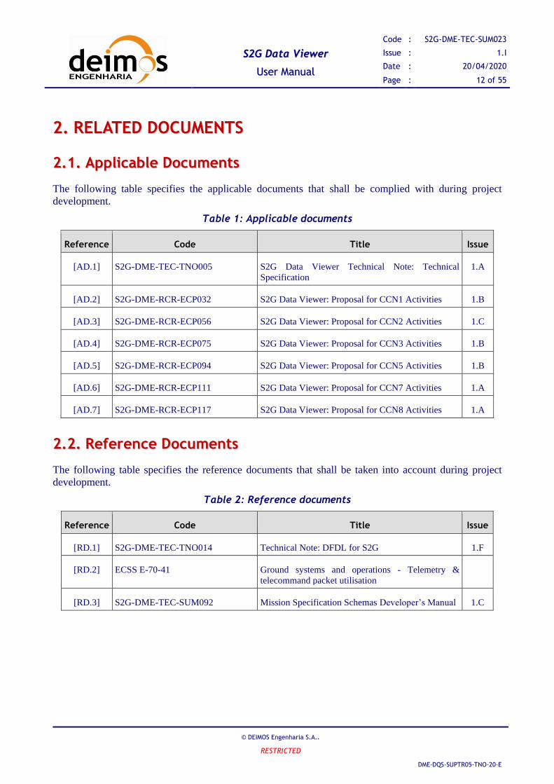
22..11.. AApppplliiccaabbllee DDooccuummeennttss
The following table specifies the applicable documents that shall be complied with during project
development.
Table 1: Applicable documents
Reference Code Title Issue
[AD.1] S2G-DME-TEC-TNO005 S2G Data Viewer Technical Note: Technical
Specification
1.A
[AD.2] S2G-DME-RCR-ECP032 S2G Data Viewer: Proposal for CCN1 Activities 1.B
[AD.3] S2G-DME-RCR-ECP056 S2G Data Viewer: Proposal for CCN2 Activities 1.C
[AD.4] S2G-DME-RCR-ECP075 S2G Data Viewer: Proposal for CCN3 Activities 1.B
[AD.5] S2G-DME-RCR-ECP094 S2G Data Viewer: Proposal for CCN5 Activities 1.B
[AD.6] S2G-DME-RCR-ECP111 S2G Data Viewer: Proposal for CCN7 Activities 1.A
[AD.7] S2G-DME-RCR-ECP117 S2G Data Viewer: Proposal for CCN8 Activities 1.A
22..22.. RReeffeerreennccee DDooccuummeennttss
The following table specifies the reference documents that shall be taken into account during project
development.
Table 2: Reference documents
Reference Code Title Issue
[RD.1] S2G-DME-TEC-TNO014 Technical Note: DFDL for S2G 1.F
[RD.2] ECSS E-70-41 Ground systems and operations - Telemetry &
telecommand packet utilisation
[RD.3] S2G-DME-TEC-SUM092 Mission Specification Schemas Developer’s Manual 1.C

SS22GG DDaattaa VViieewweerr
UUsseerr MMaannuuaall
Code : S2G-DME-TEC-SUM023
Issue : 1.I
Date : 20/04/2020
Page : 13 of 55
© DEIMOS Engenharia S.A..
RESTRICTED
DME-DQS-SUPTR05-TNO-20-E
This page intentionally left blank

SS22GG DDaattaa VViieewweerr
UUsseerr MMaannuuaall
Code : S2G-DME-TEC-SUM023
Issue : 1.I
Date : 20/04/2020
Page : 14 of 55
© DEIMOS Engenharia S.A..
RESTRICTED
DME-DQS-SUPTR05-TNO-20-E
33.. GGEETTTTIINNGG SSTTAARRTTEEDD
33..11.. IInnttrroodduuccttiioonn
Satellite house-keeping telemetry or science instruments data is transmitted to the ground sensor stations
in a packets hierarchy (see Figure 1) that is defined according to a standard format, e.g. [RD.2]. Based
on that standard format, each mission customizes the packets hierarchy to according to its specific needs
and instruments.
Sync
Marker
Reed
Solomon
Check
Symbols
CADU
VCDU
Frame
Header
End of
Packet
k-1
Packet
k
More Packets
...
Start of
Packet
m
Frame/VCDU
Packet
Header
Secondary
HeaderData
ISP
CRC
Figure 1: Hierarchy of Data received by the Ground Sensor Stations
The Space to Ground Data Viewer (S2G) displays the contents of the communication channels between
the signal-in-space and the ground systems apparatus. It interprets files containing concatenated
CADUs, TFs or ISPs, and lists of available data units and displays the fields and associated values
inside each data unit. The tool also provides a hexadecimal viewer to allow low-level data inspection.
This document uses the designation of data unit when the type of the data item (CADUs, TFs or ISPs) is
not relevant for the context.
33..22.. IInnssttaallllaattiioonn
To install S2G proceed as follows:
Linux & Windows
1. Unzip the distribution archive (list of available archives Table 3) into the installation directory.
Mac OS
1. Open dmg and drag the s2g folder from the dmg window into Application folder.
To start the application, follow the instructions in Section 3.3 (How to Start S2G).
SS22GG DDaattaa VViieewweerr
UUsseerr MMaannuuaall
Code : S2G-DME-TEC-SUM023
Issue : 1.I
Date : 20/04/2020
Page : 15 of 55
© DEIMOS Engenharia S.A..
RESTRICTED
DME-DQS-SUPTR05-TNO-20-E
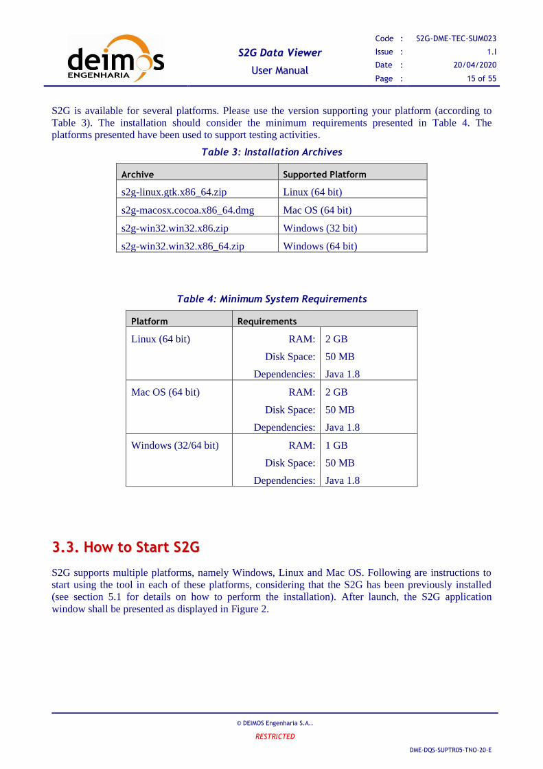
S2G is available for several platforms. Please use the version supporting your platform (according to
Table 3). The installation should consider the minimum requirements presented in Table 4. The
platforms presented have been used to support testing activities.
Table 3: Installation Archives
Archive Supported Platform
s2g-linux.gtk.x86_64.zip Linux (64 bit)
s2g-macosx.cocoa.x86_64.dmg Mac OS (64 bit)
s2g-win32.win32.x86.zip Windows (32 bit)
s2g-win32.win32.x86_64.zip Windows (64 bit)
Table 4: Minimum System Requirements
Platform Requirements
Linux (64 bit) RAM:
Disk Space:
Dependencies:
2 GB
50 MB
Java 1.8
Mac OS (64 bit) RAM:
Disk Space:
Dependencies:
2 GB
50 MB
Java 1.8
Windows (32/64 bit) RAM:
Disk Space:
Dependencies:
1 GB
50 MB
Java 1.8
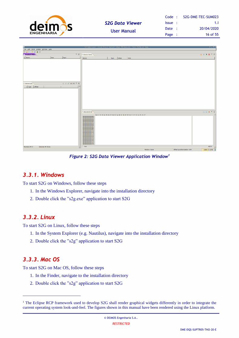
33..33.. HHooww ttoo SSttaarrtt SS22GG
S2G supports multiple platforms, namely Windows, Linux and Mac OS. Following are instructions to
start using the tool in each of these platforms, considering that the S2G has been previously installed
(see section 5.1 for details on how to perform the installation). After launch, the S2G application
window shall be presented as displayed in Figure 2.
SS22GG DDaattaa VViieewweerr
UUsseerr MMaannuuaall
Code : S2G-DME-TEC-SUM023
Issue : 1.I
Date : 20/04/2020
Page : 16 of 55
© DEIMOS Engenharia S.A..
RESTRICTED
DME-DQS-SUPTR05-TNO-20-E
Figure 2: S2G Data Viewer Application Window1
33..33..11.. WWiinnddoowwss
To start S2G on Windows, follow these steps
1. In the Windows Explorer, navigate into the installation directory
2. Double click the ”s2g.exe” application to start S2G
33..33..22.. LLiinnuuxx
To start S2G on Linux, follow these steps
1. In the System Explorer (e.g. Nautilus), navigate into the installation directory
2. Double click the ”s2g” application to start S2G
33..33..33.. MMaacc OOSS
To start S2G on Mac OS, follow these steps
1. In the Finder, navigate to the installation directory
2. Double click the ”s2g” application to start S2G
1 The Eclipse RCP framework used to develop S2G shall render graphical widgets differently in order to integrate the
current operating system look-and-feel. The figures shown in this manual have been rendered using the Linux platform.
SS22GG DDaattaa VViieewweerr
UUsseerr MMaannuuaall
Code : S2G-DME-TEC-SUM023
Issue : 1.I
Date : 20/04/2020
Page : 17 of 55
© DEIMOS Engenharia S.A..
RESTRICTED
DME-DQS-SUPTR05-TNO-20-E
33..44.. IInnssppeeccttiioonn ooff DDaattaa UUnniitt FFiilleess
The S2G Main Window provides all the functionalities supporting the inspection of files storing
CADUs, TFs and ISPs. Follow through to the section 4 for a detailed presentation of the interface
components. For information about configuring and operating S2G refer to section 5.

SS22GG DDaattaa VViieewweerr
UUsseerr MMaannuuaall
Code : S2G-DME-TEC-SUM023
Issue : 1.I
Date : 20/04/2020
Page : 18 of 55
© DEIMOS Engenharia S.A..
RESTRICTED
DME-DQS-SUPTR05-TNO-20-E
44.. SS22GG DDAATTAA VVIIEEWWEERR
S2G is composed of a window GUI that contains several views, each presenting different details of the
data stored in the binary data files – details of this GUI are presented in section 4.1.
The mission configuration files are described in section 4.2. The configuration file is an XML file that
provides information required by the GUI to display the data. The definition of the mission binary data,
namely the data fields for CADU, TF and ISPs, is defined using DFDL [RD.1].
44..11.. SS22GG GGUUII
44..11..11.. AApppplliiccaattiioonn WWiinnddooww
The S2G graphical user interface is composed of a main application window that contains several views
used to display specific information about data files. The application main window also provides the
application menu and a tool bar with shortcuts to most common actions.
Figure 3 highlights the following components of the main application window:
1. Menu
2. Tool bar
3. Product Files View
4. Data Unit List View
5. Data Unit Details View
6. Hexadecimal View
7. Status Bar
8. Memory Indicator

SS22GG DDaattaa VViieewweerr
UUsseerr MMaannuuaall
Code : S2G-DME-TEC-SUM023
Issue : 1.I
Date : 20/04/2020
Page : 19 of 55
© DEIMOS Engenharia S.A..
RESTRICTED
DME-DQS-SUPTR05-TNO-20-E
Figure 3: Components of the Application Window
S2G has been developed using the Eclipse RCP framework which renders graphical widgets differently
depending on the underlying operating system. As such, the operating system configurations, namely
the windows style and font selection, are expected to change the application’s look-and-feel.
44..11..22.. MMeennuu aanndd TToooollbbaarr
The menu and toolbar shown in Figure 4 enable the user to operate the tool. They provide actionable
menu items and buttons that allow operations such as open and close product files, or configure the
active mission.
Figure 4: Menu and Toolbar

SS22GG DDaattaa VViieewweerr
UUsseerr MMaannuuaall
Code : S2G-DME-TEC-SUM023
Issue : 1.I
Date : 20/04/2020
Page : 20 of 55
© DEIMOS Engenharia S.A..
RESTRICTED
DME-DQS-SUPTR05-TNO-20-E
44..11..22..11.. MMeennuu CCoonntteennttss
The main menu provides six sub-menus each containing specific operations – as presented Figure 5. The
menu is organized as follows:
➢ Main Menu, contains sub-menus:
o File, with operations
▪ Open File, opens a selection dialog enabling the user to choose the file to open –
see section 5.6 for details on how to open a file.
▪ Close File, closes the currently selected file – see section 5.9 for details on how to
close a file.
▪ Export, outputs to file the data units currently limited in the Data Unit List.
▪ Exit, closes the application.
o Edit
▪ Preferences…, opens the preferences dialog to edit the tool configuration
▪ Mission Configuration…, opens the configuration dialog to manage mission
configuration files.
o Tools
▪ Transform, opens the transformation dialog to transform the currently selected file
▪ Transform File…, opens the transformation dialog to transform the a file to be
selected by the user
▪ Show Report, starts the analysis of the selected file to produce a data quality report
▪ Batch Report, produces a data quality report for a selected set of files or folders
containing a given data type files.
▪ Show Plot, starts the analysis of the selected file to produce 2D data plot
▪ Mask Editor, launches the support tool to help define the synchronization masks.
o Scripts
▪ Execute Script, shows the list of scripts available for execution on S2G. The
selected script shall be executed over the selected product file.
o Window
▪ Reset Views, allows the user to reset the default location of the several views.
▪ Toggle Find Bar, shows/hides the find bars associated with field details and
hexadecimal views.
o Help
▪ Open Help, displays the S2G help page
▪ Documentation, links to support documentation for S2G/DFDL.
▪ About S2G, displays the S2G development credits dialog.
▪ Check for updates, connects to S2G server to check for an updated version of the
software or the mission configuration files.

SS22GG DDaattaa VViieewweerr
UUsseerr MMaannuuaall
Code : S2G-DME-TEC-SUM023
Issue : 1.I
Date : 20/04/2020
Page : 21 of 55
© DEIMOS Engenharia S.A..
RESTRICTED
DME-DQS-SUPTR05-TNO-20-E
Figure 5: Menu Details
44..11..22..22.. TToooollbbaarr CCoonntteennttss
The toolbar provides easy access to usual operations. As observed in Figure 6, the following operations
are available (in sequence):
➢ Open File
➢ Close File
➢ Edit Preferences
➢ Toggle Find Bars
➢ Show Report
➢ Show Plot
➢ Transform
Figure 6: Toolbar Details
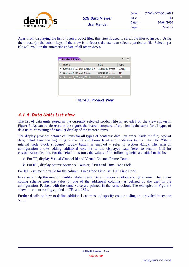
44..11..33.. PPrroodduucctt FFiilleess vviieeww
The Product Files view (presented in Figure 7) displays the list of open files in a tabular form. The view
provides information about file size and, when hovering the mouse pointer over the file name, shows a
tooltip with the complete file path. Additionally the view contains a visual clue on whether the file has
already been checked for errors by producing the Quality Report (refer to section 5.9) – ‘V’ for checked,
‘?’ for not yet checked.
SS22GG DDaattaa VViieewweerr
UUsseerr MMaannuuaall
Code : S2G-DME-TEC-SUM023
Issue : 1.I
Date : 20/04/2020
Page : 22 of 55
© DEIMOS Engenharia S.A..
RESTRICTED
DME-DQS-SUPTR05-TNO-20-E
Apart from displaying the list of open product files, this view is used to select the files to inspect. Using
the mouse (or the cursor keys, if the view is in focus), the user can select a particular file. Selecting a
file will result in the automatic update of all other views.
Figure 7: Product View
44..11..44.. DDaattaa UUnniittss LLiisstt vviieeww
The list of data units stored in the currently selected product file is provided by the view shown in
Figure 8. As can be observed in the figure, the overall structure of the view is the same for all types of
data units, consisting of a tabular display of the content items.
The display provides default columns for all types of contents: data unit order inside the file; type of
data, offset from the beginning of the file and lower level error indicator (active when the “Show
internal code block structure” toggle button is enabled – refer to section 4.1.5). The mission
configuration allows adding additional columns to the displayed data (refer to section 5.13 for
customization details). For the default missions, the values of the following fields are added to the list:
➢ For TF, display Virtual Channel Id and Virtual Channel Frame Count
➢ For ISP, display Source Sequence Counter, APID and Time Code Field
For ISP, assume the value for the column ‘Time Code Field’ as UTC Time Code.
In order to help the user to identify related items, S2G provides a colour coding scheme. The colour
coding scheme uses the value of one of the additional columns, as defined by the user in the
configuration. Packets with the same value are painted in the same colour. The examples in Figure 8
show the colour coding applied to TFs and ISPs.
Further details on how to define additional columns and specify colour coding are provided in section
5.13.

SS22GG DDaattaa VViieewweerr
UUsseerr MMaannuuaall
Code : S2G-DME-TEC-SUM023
Issue : 1.I
Date : 20/04/2020
Page : 23 of 55
© DEIMOS Engenharia S.A..
RESTRICTED
DME-DQS-SUPTR05-TNO-20-E
Figure 8: Data Units List View
The Data Units List enables the user to select a data unit by: clicking over the data unit with the mouse;
through cursor keys (when the view is in focus); or pressing next/previous buttons – see Figure 9. Upon
selection of a unit, the data unit details view and hexadecimal view are automatically synchronized with
the newly selected item: the data unit details view displays the internal structure of the item; and the
hexadecimal view auto-scrolls the show the beginning of the item.
After selecting a specific field in the Content Details view, the user can re-focus the selection on the
content item by double-clicking on the item – this action clears any existing field selection.
The view enables three functionality buttons:
➢ On demand quality check (signalled by a check mark): apply the Reed-Solomon check (at CADU
level) or the CRC check (TF level) for the selected data unit. Upon executing the quality check
the status of the RS and CRC fields in the Data Unit details view changes depending on the result
of the check (refer to section 4.1.5). The check applies only for the data level of the open file, i.e.,
if a CADU file is open displaying also the CRC fields of the underlying TF, then the quality
check shall only apply to the RS at CADU level;
➢ Find data unit (signalled by the bull’s-eye mark): allows jumping to a given data unit given its
order number inside the file. When this function is activated the indication “Jump to data unit:” is
displayed in the information bar allowing the user to enter the intended unit number, confirming
with “Enter” or cancelling with “Esc” key.
➢ Limit Range (signalled by the narrowing icon): allows limiting the display of data to a given time
window. The user is requested an interval of data unit numbers and the Data Unit List shall
display only the data units within that interval. This limitation can then be switched on/off.
➢ Export Range (signalled by the file icon): outputs to file the data units currently limited in the
Data Unit List (as per the Limit Range capability).
The view provides an information bar in the lower part of the window, were the number of available
units is displayed. The information bar also displays the order index of the currently selected unit. The
latter is a helpful indication to the user as the unit selection is not affected when the unit goes out of
view.

SS22GG DDaattaa VViieewweerr
UUsseerr MMaannuuaall
Code : S2G-DME-TEC-SUM023
Issue : 1.I
Date : 20/04/2020
Page : 24 of 55
© DEIMOS Engenharia S.A..
RESTRICTED
DME-DQS-SUPTR05-TNO-20-E
Select Next/Previous ItemView Title indicates the type of item
Number of available items Currently selected item
Additional columns,
defined in configuration
Colour coding helps
identify related items
Figure 9: Details of the Data Unit List View
When S2G detects problems or inconsistencies in a data unit, it is highlighted in the view as follows:
➢ data units with problems in data stream synchronization, are highlighted by the entire background
of the row in red - Figure 10 (this colour can be consulted in the Preferences, refer to section
4.1.7).
➢ data units with schema syntactic errors (such as expressions malformed or element paths not
found), are highlighted by the entire background of the row in orange - Figure 11 (this colour
can be consulted in the Preferences, refer to section 4.1.7).
➢ data units with minor inconsistencies (such as having fields with unexpected values), are
highlighted using a red font - Figure 12 (this colour can be configured in the Preferences, refer
to section 4.1.7).

SS22GG DDaattaa VViieewweerr
UUsseerr MMaannuuaall
Code : S2G-DME-TEC-SUM023
Issue : 1.I
Date : 20/04/2020
Page : 25 of 55
© DEIMOS Engenharia S.A..
RESTRICTED
DME-DQS-SUPTR05-TNO-20-E
Figure 10: Data stream
synchronization error
highlighting (red background) in
the Data Unit List View.
Figure 11: Schema syntactic error
highlighting (orange background)
in the Data Unit List View.
Figure 12: Minor inconsistencies
error highlighting (red font) in
the Data Unit List View.
S2G identifies idle data units highlighting them in the list with an italic grey font.
44..11..55.. DDaattaa UUnniitt DDeettaaiillss vviieeww
Each data unit inside a file is defined in the mission data schema through a hierarchical structure, in
which leafs are the actual fields of the item. These fields are then grouped into sequences of fields, or
with other groups. The hierarchical structure of each item is displayed in the Contents Details view –
Figure 13 shows the content of an ISP.
The hierarchy of nodes can be expanded to display details of field organization and values. Each
element of the hierarchy is represented in a tabular way, with the following attributes:
➢ The name
➢ The type of the representation (this type is defined by the user, and defines how the value is
represented in the value column.
➢ The value, according to the type of representation
➢ The size of the element (the actual size of the element if a field; otherwise the sum of the size of
child elements).
The values are represented according to default representation types specified in [RD.1]. To enhance
data inspection, the tool displays a tooltip (as shown in Figure 13) that shows alternative representations
of the field values in Binary, Hexadecimal and Unsigned Integer.
When representation type is of ‘Time’ type, time is displayed as UTC time string (as shown in Figure
13).
In the Binary representation the octets assigned to the field are fully represented, replacing the irrelevant
bits with a ‘.’. For both Hexadecimal and Unsigned Integer representations the underlying octets is
cleaned of the irrelevant bits and then right shifted before displayed in the tooltip.

SS22GG DDaattaa VViieewweerr
UUsseerr MMaannuuaall
Code : S2G-DME-TEC-SUM023
Issue : 1.I
Date : 20/04/2020
Page : 26 of 55
© DEIMOS Engenharia S.A..
RESTRICTED
DME-DQS-SUPTR05-TNO-20-E
Each element representing a field or a group of fields can be selected using the mouse or the cursor keys
(when view is in focus). When an element is selected, the bytes in which it is stored are highlighted in
the Hexadecimal view.
Figure 13: Contents Details View (ISP Example)
When S2G detects inconsistencies in a data unit field, the field is highlighted by being show in red (as
shown in Figure 13).
Error detection fields like Reed-Solomon field in CADUs or CRC field in TF are highlighted by being
shown in blue. This colour means the quality check hasn’t been performed for that particular data unit.
Upon performing the quality check either by generating a report or by using the on-demand quality
check functionality (see section 4.1.4) the colour shall change to red in case of failed check or green in it
passed.
The underlying tree structure that supports the contents details can be expanded or collapsed using the
tree button on the top right corner. The lock button enables/disables showing internal block code
structure (e.g. in a TF showing the contained ISPs).
The view enables four functionality buttons:
➢ Show internal code block structure (signalled by a lock icon): show/hide the underlying structure
of data levels contained in the current file data level (e.g. ISPs inside a TF);
➢ Expand/Collapse the entire tree structure (signalled by the hierarchy icon);
➢ Show Packet Details Colouring (signalled by the colour palette icon): Colours the tree structure
highlighting the predefined sections of the shown packet;
➢ Visually propagate lower level errors (signalled by the beacon icon): highlight in error indication
dolour the whole path from the lower level field containing an error up to the tree structure top.
44..11..66.. HHeexxaaddeecciimmaall vviieeww
The Hexadecimal view, shown in Figure 14, displays the bytes of the files in two areas, indexed by the
offset from the beginning of the file:

SS22GG DDaattaa VViieewweerr
UUsseerr MMaannuuaall
Code : S2G-DME-TEC-SUM023
Issue : 1.I
Date : 20/04/2020
Page : 27 of 55
© DEIMOS Engenharia S.A..
RESTRICTED
DME-DQS-SUPTR05-TNO-20-E
➢ On the left, a table with the bytes/octets (displayed in hexadecimal)
➢ On the right, a table with the text representation of the file contents.
In order to assist inspection of the file contents it is important to map the structure of the file contents
(i.e. CADUs, TFs, and ISPs) to the actual raw data. The Hexadecimal view provides this mapping
mechanism. This view provides the following highlights.
➢ The bytes related to the selected item in the Contents List View are highlighted – the fields
directly below the parent node of the hierarchy are highlighted with different colours. Figure 14
shows these fields (usually representative of standard packet sections) in green, yellow and
blue.
➢ The bytes related to the selected element in the Content Details View are highlighted. This
selection is represented in pink on Figure 14.
Figure 14: Hexadecimal View with Standard Sections
Additionally to the automatic highlight provided by S2G, the user can also select a group of bytes using
mouse gestures (i.e. click-and-drag selection). When performing mouse selection, the selected area is
highlight in grey.
Besides selection, the tool allows a jump to functionality in which the user can jump to the item related
to a specific byte. This functionality is activated by double-clicking on a previously mouse selected area.
This action results in automatic selection of the item in the Content List View and auto-scroll of the
Hexadecimal view to the beginning of the selected item. Any field selection in Content Details view is
cleared by this action.
The hexadecimal view provides an information bar with information about the current selection. Notice
that the provided information (Offset, Value and Selection) is related to: in first place, the mouse
selection if any; otherwise the information represents the selection related to the field in Content Details
view.
The values of the offsets on the left of the octet table and, on the information bar, the offset and value of
current selection can be displayed in either decimal or hexadecimal. To toggle between these two
modes, the user has just to double click over the Representation label – “Hex” on the bottom left of

SS22GG DDaattaa VViieewweerr
UUsseerr MMaannuuaall
Code : S2G-DME-TEC-SUM023
Issue : 1.I
Date : 20/04/2020
Page : 28 of 55
© DEIMOS Engenharia S.A..
RESTRICTED
DME-DQS-SUPTR05-TNO-20-E
Figure 14. The value of the label is either “Hex” or “Dec” according to selected representation
(Hexadecimal or Decimal, respectively).
The Hexadecimal view also provides functionality to Find Position (signalled by the bull’s-eye mark in
Figure 15): allowing jumping to a given data unit given its offset. When this function is activated the
indication “Jump to data unit:” is displayed in the information bar allowing the user to enter the intended
offset either in Hexadecimal or Decimal format depending on the selected display mode.
The user can modify the number of columns visible, by clicking on the plus/minus buttons on the top
right of the view.
For the specific case of Transfer Frames, the Hexadecimal View highlights the first byte of the
instrument source packet that begins in the frame data. This byte is highlighted by placing a red box at
the octet corresponding location (see near mouse pointer in Figure 15)
Figure 15: Hexadecimal View with First Packet in TF
44..11..77.. PPrreeffeerreenncceess
The preferences or configuration parameters of the tool can be updated by activating the menu item
“Edit” → “Preferences” to display the preferences page. The dialog to select the active mission is shown
in Figure 16. More details on how to select active mission on section 5.4.

SS22GG DDaattaa VViieewweerr
UUsseerr MMaannuuaall
Code : S2G-DME-TEC-SUM023
Issue : 1.I
Date : 20/04/2020
Page : 29 of 55
© DEIMOS Engenharia S.A..
RESTRICTED
DME-DQS-SUPTR05-TNO-20-E
Figure 16: Preferences (Mission Configuration)
S2G provides a Mission Explorer interface as part of the preferences page – see Figure 17. This allows
the user to check some details of the configuration without having to open the xml files with the mission
data configuration.
Figure 17: Preferences (Mission Explorer)
S2G provides general Application Settings as part of the preferences page – see Figure 18. This allows
the user change basic behaviour of the tools, namely: data unit offset synchronization, enable/disable the
update check at startup, disable/enable the generation of debug information; configure the number of
events to be stored in the quality report, manage the parameters the configure the offset file cache (set
maximum cached files and reset the cache), enable/reset ambiguous data definition selection and also
select the colour used to highlight severe errors in the Data Unit List.

SS22GG DDaattaa VViieewweerr
UUsseerr MMaannuuaall
Code : S2G-DME-TEC-SUM023
Issue : 1.I
Date : 20/04/2020
Page : 30 of 55
© DEIMOS Engenharia S.A..
RESTRICTED
DME-DQS-SUPTR05-TNO-20-E
Figure 18: Preferences (Application Settings)
44..11..77..11.. MMiissssiioonn CCoonnffiigguurraattiioonn
The mission specification available in the tool can be configured by activating the menu item “Edit” →
“Mission Configuration” to display the configuration page. This functionality enables the user to extend
S2G to support custom missions. How to configure new missions is described on section 5.5
(customization of mission data is covered in section 5.13).
Figure 19: Mission Configuration
44..11..88.. HHeellpp aanndd AAbboouutt
The help can be displayed through the menu item “Help” -> “Open Help”. How the help is displayed
depends on the Platform/OS. In Windows a window with the help is displayed, while in Mac and Linux
OS the help information is accessed through the pre-defined web browser. Since help is provided
through a built-in webpage client, firewall access must be granted to the tool for correct usage. Figure
20 provides an example of the Help interface in Linux.

SS22GG DDaattaa VViieewweerr
UUsseerr MMaannuuaall
Code : S2G-DME-TEC-SUM023
Issue : 1.I
Date : 20/04/2020
Page : 31 of 55
© DEIMOS Engenharia S.A..
RESTRICTED
DME-DQS-SUPTR05-TNO-20-E
Figure 20: Help Dialog (in Linux platform)
The about dialog is accessible through the menu item “Help” -> “About”. Figure 21 provides the about
dialog.
Figure 21: About Dialog
44..22.. MMiissssiioonn CCoonnffiigguurraattiioonn
S2G takes a set of mission configurations as inputs, composed of several separate files. The tool
provides a set of default mission configurations, that the user can expand by following the procedure
described in section 5.5.
The default mission configuration files are available inside the workspace location, which is a folder
containing auxiliary data, created during the first execution of the application. The location of the
workspace depends on the installation platform, as follows:
➢ For Windows and Linux, the workspace location is created inside the installation directory

SS22GG DDaattaa VViieewweerr
UUsseerr MMaannuuaall
Code : S2G-DME-TEC-SUM023
Issue : 1.I
Date : 20/04/2020
Page : 32 of 55
© DEIMOS Engenharia S.A..
RESTRICTED
DME-DQS-SUPTR05-TNO-20-E
➢ For Mac OS, the workspace location is created inside the app directory related to S2G.
Inside the workspace, each mission configuration is stored in a separate directory available through
$WORKSPACE/resources/data.
The files composing the Mission Configuration (Figure 22) provide a wide range of configuration
parameters used by the application, and can be divided in two groups:
➢ the Mission Definition file is an xml file that contains the mission definition parameters used by
the GUI (such as mission name, the list of searchable or hidden fields); this file also contains the
reference to the schemas defining the structure of the binary data.
➢ the Mission Data Definition schema files are a set of schemas that define the binary contents of
the several levels of packages (CADU, TF and ISP) based on the DFDL [RD.1].
mission_CADU.xsd
mission_VCDU.xsd
mission_ISP.xsd
mission_CADUtypes.xsd
mission_TFtypes.xsd
mission_ISPtypes.xsd
includes
includes
includes
Includes
mission.xml
refers
refe
rs
refers
mission_ISPData.xsd
includes
CCSDSTIme.xsd
includes
Figure 22: Mission Configuration files structure
The following sections present details of the two types of configuration files.
44..22..11.. MMiissssiioonn DDeeffiinniittiioonn FFiillee
The Mission Definition file is an xml file (see Figure 23 for an example) that specifies list of schemas
used to interpret the binary data. The file stores the mission name, and it also provides for each type of
file, additional information used by the GUI.
Each schema element in the file defines:
➢ The file, which is the actual file containing the schema definition
➢ The search element, that stores the list of fields that should appear as option in the find bar
➢ The invisible element that stores the list of fields that should be hidden from the hierarchical
representation in the Content Details view.
➢ The packet_list_columns element that stores the list of fields to be displayed as extra columns in
the Contents List view.
➢ The masks element specifies the mask(s) used for synchronization detection.
➢ The plots element defines the charts applicable to the data.
➢ The transformation element specifies the data transformation applicable to the data.

SS22GG DDaattaa VViieewweerr
UUsseerr MMaannuuaall
Code : S2G-DME-TEC-SUM023
Issue : 1.I
Date : 20/04/2020
Page : 33 of 55
© DEIMOS Engenharia S.A..
RESTRICTED
DME-DQS-SUPTR05-TNO-20-E
A field is defined by a name attribute, with the path of the field as value. The path of the field is defined
by the concatenation of the several item names in the hierarchical structure defining the binary data.
Only a field, defined under the packet_list_columns, can have an attribute indicator (with value colour).
The presence of this indicator is used to select the value during colour coding of the packets.
Figure 23: Example of Mission Definition file
44..22..22.. MMiissssiioonn DDaattaa DDeeffiinniittiioonn SScchheemmaass
The Mission Data Definition schemas are XSD schemas adapted (according to [RD.1]) to describe the
structure of the binary items inside the data files. Although each schema file could have been defined
independently, considering that they can share schema types, the structure shown in Figure 22 has been
used for the default missions provided with S2G. Section 5.13 provides some guidelines on how the user
can customize an existing mission configuration.
SS22GG DDaattaa VViieewweerr
UUsseerr MMaannuuaall
Code : S2G-DME-TEC-SUM023
Issue : 1.I
Date : 20/04/2020
Page : 34 of 55
© DEIMOS Engenharia S.A..
RESTRICTED
DME-DQS-SUPTR05-TNO-20-E
This page intentionally left blank

SS22GG DDaattaa VViieewweerr
UUsseerr MMaannuuaall
Code : S2G-DME-TEC-SUM023
Issue : 1.I
Date : 20/04/2020
Page : 35 of 55
© DEIMOS Engenharia S.A..
RESTRICTED
DME-DQS-SUPTR05-TNO-20-E
55.. OOPPEERRAATTIIOONNSS
55..11.. IInnssttaallllaattiioonn PPrroocceedduurree
See section 3 (Getting Started).
55..22.. LLaauunncchh SS22GG
See section 3 (Getting Started).
55..33.. EExxiitt SS22GG
To close S2G proceed as follow:
1. Select menu “File” → “Exit”.
55..44.. SSeelleecctt AAccttiivvee MMiissssiioonn
The file types available when opening a data file is related to the currently active mission. To change the
active mission, proceed as follow:
1. Open the preferences pages (“Edit” → “Preferences”).
2. Inside the “S2G Data Viewer”, select the “Mission Configuration” page.
3. Select the new active mission using the combo box “Selected Mission” shown in Figure 24.
4. Press OK to finish configuration setup.

SS22GG DDaattaa VViieewweerr
UUsseerr MMaannuuaall
Code : S2G-DME-TEC-SUM023
Issue : 1.I
Date : 20/04/2020
Page : 36 of 55
© DEIMOS Engenharia S.A..
RESTRICTED
DME-DQS-SUPTR05-TNO-20-E
Figure 24: Active Mission Configuration
55..55.. MMiissssiioonn CCoonnffiigguurraattiioonn MMaannaaggeemmeenntt
S2G enables the use of customized missions, loading their data at startup. This functionality is available
by activating the menu item “Edit” → “Mission Configuration” (shown in Figure 25). The user is able
to: export an existing mission (to have access to the defining files); import a new mission; and discard
an existing mission. From the point of view of S2G there are two categories of mission definitions: the
standard missions and the custom missions.
Figure 25: Mission Configuration
55..55..11.. EExxppoorrtt MMiissssiioonn
To export existing mission files proceed as follow:

SS22GG DDaattaa VViieewweerr
UUsseerr MMaannuuaall
Code : S2G-DME-TEC-SUM023
Issue : 1.I
Date : 20/04/2020
Page : 37 of 55
© DEIMOS Engenharia S.A..
RESTRICTED
DME-DQS-SUPTR05-TNO-20-E
1. Launch the Mission Configuration dialog through menu “Edit” → “Mission Configuration”
(Figure 25)
2. Select the mission category to manage (custom or standard) in the left hand side of the dialog;
3. Select the mission file to be exported in the missions list;
4. Press button “Export Mission” and select the directory where to save the file, finishing with OK.
After this step, the mission jar file shall be available in the chosen location.
55..55..22.. DDiissccaarrdd MMiissssiioonn
To discard existing mission files proceed as follow:
1. Launch the Mission Configuration dialog through menu “Edit” → “Mission Configuration”
(Figure 25)
2. Select the mission category to manage (custom or standard) in the left hand side of the dialog;
3. Select the mission file to be discarded in the missions list;
4. Press button “Discard Mission” confirming with OK the deletion message that is shown. After
this step, the mission is no longer available in the application.
55..55..33.. IImmppoorrtt MMiissssiioonn
To import a new mission file proceed as follow:
1. Launch the Mission Configuration dialog through menu “Edit” → “Mission Configuration”
(Figure 25)
2. Select the mission category to manage (custom or standard) in the left hand side of the dialog;
3. Press button “Import Mission”;
4. Select the file to import from the file open dialog and finish with OK. After this step the new
mission shall be available in the application.
55..66.. OOppeenn FFiillee
To open a data file proceed as follow:
1. Launch the Open file dialog through menu “File” → “Open” (Figure 26)
Note: this step can also be performed thought the “Open File” button in the toolbar; or using the
keyboard shortcut (Ctrl-O).
2. Select the type of file to be open, in the file type combo box.
3. Select the file to open, and finish with OK. After this step, a progress dialog is shown while
loading the file (Figure 27), and the file will appear listed in the Product Files view (Figure 28).

SS22GG DDaattaa VViieewweerr
UUsseerr MMaannuuaall
Code : S2G-DME-TEC-SUM023
Issue : 1.I
Date : 20/04/2020
Page : 38 of 55
© DEIMOS Engenharia S.A..
RESTRICTED
DME-DQS-SUPTR05-TNO-20-E
Figure 26: Open file dialog (with types of files)
Figure 27: Progress bar when loading file
Figure 28: S2G Main Window displaying file contents

SS22GG DDaattaa VViieewweerr
UUsseerr MMaannuuaall
Code : S2G-DME-TEC-SUM023
Issue : 1.I
Date : 20/04/2020
Page : 39 of 55
© DEIMOS Engenharia S.A..
RESTRICTED
DME-DQS-SUPTR05-TNO-20-E
While opening a file, S2G may try (if data unit offset synchronisation is enabled in the Preferences) to
match the bit patterns (if any) defined by the mission definition file (see section 4.2.1 for details) in
order to check for data units synchronization. When synchronization errors are detected S2G will issue a
warning to the user, as seen in Figure 29. The user can then generate the full quality report to access
detailed information about synchronization errors. Note that the current offset synchronisation status
(on/off) is indicated in the status bar at the bottom of the main screen.
Figure 29: Warning dialog when Synchronization Errors are detected
55..77.. DDaattaa UUnniitt IInnssppeeccttiioonn
To inspect the content of a file in the Product Files list view, consider the following operations.
55..77..11.. IInnssppeecctt aa DDaattaa UUnniitt
To inspect the contents of a file, proceed as follow:
1. In the Data Unit list view, scroll to the packet to inspect.
2. Select by clicking over the row of the desired data unit
Note: This selection can also be performed with the cursor keys; and the packet selection is
highlighted in a shade of pink.
After step 2), the selected item is represented in the Data Unit Details view in a hierarchical structure,
and the Hexadecimal view is automatically scrolled to show the beginning of the packet in the file.
55..77..22.. IInnssppeecctt DDaattaa UUnniitt ffiieellddss
To inspect the field of a content item, proceed as follow:
1. In the Data Unit Details view, expand the nodes of the item structure to display the field to
inspect.
Note: The content item structure is shown only if a file and data unit is selected.
2. Select by clicking over the desired item field. Passing the mouse over the field value displays
alternate representations of the field value in a tooltip.
Note: the data unit field selection is highlighted in a shade of pink.
After step 2), the byte storing the selected item field is highlighted with a pink shade in the hexadecimal
view.

SS22GG DDaattaa VViieewweerr
UUsseerr MMaannuuaall
Code : S2G-DME-TEC-SUM023
Issue : 1.I
Date : 20/04/2020
Page : 40 of 55
© DEIMOS Engenharia S.A..
RESTRICTED
DME-DQS-SUPTR05-TNO-20-E
55..77..33.. CClleeaarr DDaattaa UUnniitt ffiieelldd sseelleeccttiioonn
To clear the selection of Data Unit field, proceed as follow:
1. In the Data Unit List view, scroll the currently selected item into view
2. Double click on the currently selected data unit.
55..88.. SSeeaarrcchh
55..88..11.. FFiieelldd VVaalluuee
S2g enables the search by value of specific data unit fields. Section 5.13 describes how to customize
searchable fields. To search for a specific value proceed as follows:
1. Display the find bar (by activating the menu item “Window” → “Toggle Find Bar” or through the
keyboard shortcut Ctrl + “F”) – the find bar is shown on top of the Data Unit Details view as in
Figure 30.
2. Select the field to search in the combo listing the searchable fields
3. Enter the value to search in the text box labeled “Find:”
Note: if the data unit has no searchable fields the list will be available, and any search will fail.
4. Press enter to activate the forward search. Forward and backward search can also be activated
using down and up arrow, respectively.
Figure 30: Find Bar for Field Search
55..88..22.. HHeexxaaddeecciimmaall VVaalluuee
S2G enables the search by hexadecimal and text file content. To search for a raw file content proceed as
follows:
1. Display the find bar (by activating the menu item “Window” → “Toggle Find Bar” or through the
keyboard shortcut Ctrl + “F”) – the find bar is shown on top of the Hexadecimal view as in
Figure 31.
2. Select the search mode from the combo box listing: Hexadecimal to search for hexadecimal
values (contents on the left side of the view); Text to search for text (contents on the right side of
the view).
3. Enter the value to search in the text box labeled “Find:”

SS22GG DDaattaa VViieewweerr
UUsseerr MMaannuuaall
Code : S2G-DME-TEC-SUM023
Issue : 1.I
Date : 20/04/2020
Page : 41 of 55
© DEIMOS Engenharia S.A..
RESTRICTED
DME-DQS-SUPTR05-TNO-20-E
Note 1: Hexadecimal values cannot contain spaces (e.g. search for AE3B to find the two next bytes
“AE 3B” in the file.
Note 2: Non-printable characters are represented by the dot (‘.’) character. As such, the dot
character cannot be used for matching during search.
4. Press enter to activate the forward search. Forward and backward search can also be activated
using down and up arrow, respectively.
Figure 31: Find Bar for Hexadecimal Search
55..99.. QQuuaalliittyy RReeppoorrtt
To generate a quality report proceed as follows:
1. Select the file in the Product View.
2. Select menu “Tools” → “Show Report” (or click the “Show Report” button in the toolbar). After
this step, while the report is being generated the user can evaluate the progress in a progress
dialog.
3. When the report is finished, a dialog is shown (Figure 32) to the user that enables opening the
report in an external browser from a default location, or save it in a user specified location.
Figure 32: Finished Quality report dialog
In order to avoid a consumption of a large amount of memory, S2G limits the number of events in the
report (this number can be configured in the Application Settings preferences). The information about
the size of the report is provided in the dialog, in order to help the user evaluate if displaying the report
in a web browser is feasible.
The report is stored in XML format, which when rendered by a Web Browser with the style sheet
provided by S2G is displayed as shown in Figure 33.

SS22GG DDaattaa VViieewweerr
UUsseerr MMaannuuaall
Code : S2G-DME-TEC-SUM023
Issue : 1.I
Date : 20/04/2020
Page : 42 of 55
© DEIMOS Engenharia S.A..
RESTRICTED
DME-DQS-SUPTR05-TNO-20-E
Figure 33: Quality report displayed in external Web Browser
55..99..11.. DDeessccrriippttiioonn ooff tthhee QQuuaalliittyy RReeppoorrtt ccoonntteennttss
The Quality Report is divided in 3 sections:
➢ File Properties, containing information about the file selected for quality check;
➢ Summary, presenting a list of items summarizing the result of the quality check;
➢ Events, containing a list of detailed information items for each event detected during the quality
check.
The content of each section is detailed in the next sections of this document. Please note that the checks
performed by the quality report are done over uncorrected data. Also, Reed-Solomon and CRC fields are
not checked on-the-fly (errors reported in the quality report, are not highlighted in the data unit fields
view). These checks are only performed in the scope of the quality report.
55..99..11..11.. FFiillee PPrrooppeerrttiieess
This section is equal for all file types and contains the items in Table 5.

SS22GG DDaattaa VViieewweerr
UUsseerr MMaannuuaall
Code : S2G-DME-TEC-SUM023
Issue : 1.I
Date : 20/04/2020
Page : 43 of 55
© DEIMOS Engenharia S.A..
RESTRICTED
DME-DQS-SUPTR05-TNO-20-E
Table 5: File Properties in the Quality Report
File Properties Scrambled
CADU Unscrambled
CADU TF ISP
File Name x x x x
File Path x x x x
File Size x x x x
Report Date x x x x
Report Generation Time x x x x
55..99..11..22.. SSuummmmaarryy
The items listed in the Summary section of the quality report depend on the type of the input product.
Table 6 presents a description of the listed items for each type.
Table 6: Summary information in the Quality Report
Item Scrambled
CADU Unscrambled
CADU TF ISP
Total Nr of Synchronization Errors x x x x
Number of CADUs x x
Number of RS errors in the header x x
Total Number of TFs x
Number of Idle TFs x
Number of Frame Counter Discontinuities x
Total Number of ISPs x
Number of Idle ISPs x
First Timestamp x
Last Timestamp x
Number of SSC gaps x
Number of Duplicated ISPs x
Number of ISPs Timestamp Discontinuities x
Number of CRC errors x

SS22GG DDaattaa VViieewweerr
UUsseerr MMaannuuaall
Code : S2G-DME-TEC-SUM023
Issue : 1.I
Date : 20/04/2020
Page : 44 of 55
© DEIMOS Engenharia S.A..
RESTRICTED
DME-DQS-SUPTR05-TNO-20-E
55..99..11..33.. EEvveennttss
This section contains the detailed information of detected events. If no event is detected, the section is
empty. The events that can be detected and displayed depend on the type of the input product.
Each event is presented in the form of a table, containing always (among other relevant fields specific of
the event):
➢ Report entry number;
➢ The event message;
➢ Data unit number (i.e., number of the CADU, TF or ISP within the file);
➢ Data unit offset (i.e., the offset in bytes from the CADU, TF or ISP file origin);
Table 7 shows the description of the main events detected by S2G according to the product type.
Table 7: Events in the Quality Report
Event Message Description Scrambled
CADU Unscrambled
CADU TF ISP
Stream
Synchronization
The synchronization was lost at some point.
The lost offset where the sync was lost is
detailed in the event, as well as the re-sync
offset.
x x x x
Reed Solomon
uncorrectable
errors detected
(during quality
check)
Reed-Solomon errors that cannot be corrected
were detected in the data unit (due to the
large amount of the incorrect bits, the RS
algorithm is unable to recover all errors). x
Reed Solomon
errors detected
(during quality
check)
Correctable Reed-Solomon errors were
detected in the data unit.
The interleaving level, symbol offset,
expected value and found value are provided
for each correctable error detected in the data
unit.
x
CRC error
detected
The calculation of the CRC over the data unit
fields does not match the CRC value
provided.
SSC, APID and Time Code Field values are
provided in the event details.
x x
Frame Counter
discontinuity
A jump from the previous transfer frame
number and the current one was detected,
indicating a discontinuity.
Information about the previous TF and the
current one is provided in the event details.
x
Unknown APID
detection
An invalid APID value was detected. x

SS22GG DDaattaa VViieewweerr
UUsseerr MMaannuuaall
Code : S2G-DME-TEC-SUM023
Issue : 1.I
Date : 20/04/2020
Page : 45 of 55
© DEIMOS Engenharia S.A..
RESTRICTED
DME-DQS-SUPTR05-TNO-20-E
Event Message Description Scrambled
CADU Unscrambled
CADU TF ISP
Invalid SSC Gap
detected
A jump in the SSC between the previous ISP
and the current one was detected.
Information about the previous ISP and the
current one is provided in the event details.
x
Timestamp
discontinuity
A jump between the previous Time Code
Field and the current one was detected,
indicating a discontinuity. The timestamp is
expected to be continuously increasing.
Information about the previous ISP and the
current one is provided in the event details.
x
Duplicated ISP An ISP with the same SSC, APID and Time
Code Field values as a previously analyzed
ISP is detected.
Information about the original ISP and the
current one is provided in the event details.
x
55..99..22.. BBaattcchh QQuuaalliittyy RReeppoorrtt GGeenneerraattiioonn
The user can also generate quality reports in batch mode for a: (a) set of selected files or (b) all files in a
set of selected folders. When choosing to generate the report for a set of folder the user may choose to
iterate recursively into existing sub-folders. In either mode the user is prompted to select of given file
type and the report generation proceeds assuming all selected files correspond to that data type. The
quality report file is stored in the same location of the source data file, with the same name and
extension ‘xml’.
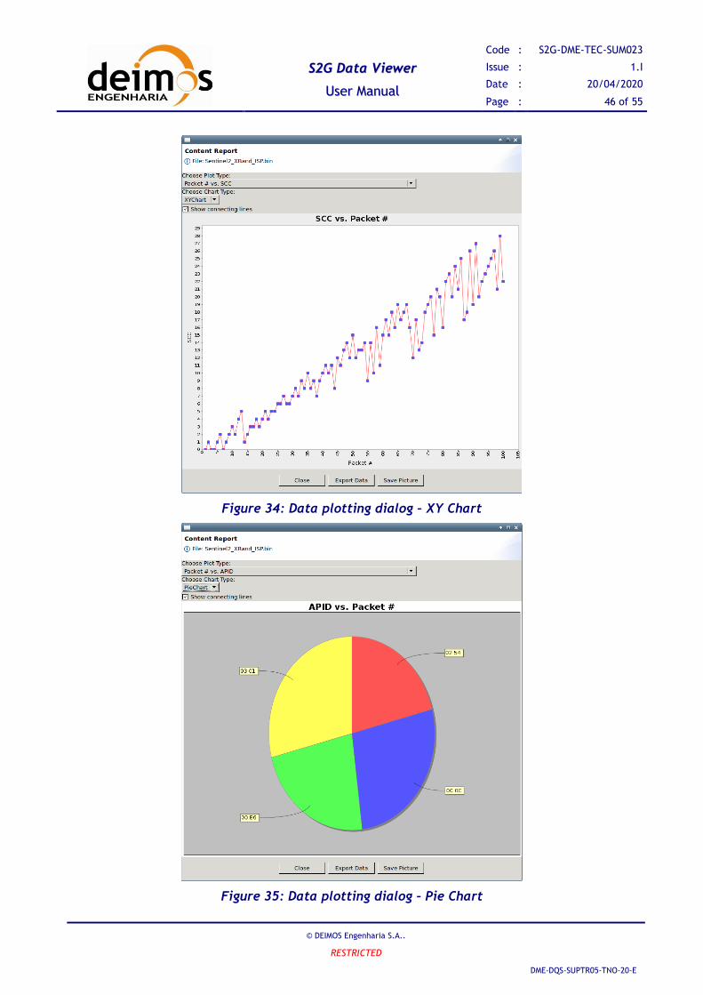
55..1100.. DDaattaa PPlloottttiinngg
To generate a plot of the data proceed as follows:
1. Select the file in the Product View.
2. Select menu “Tools” → “Show Plot” (or click the “Show Plot” button in the toolbar). After this
step, while the plot is being generated the user can evaluate the progress in a progress dialog.
3. When finished, the plot is shown in dialog (Figure 34). The user can display the several plot types,
by selecting them in the top combo box. The user can also select between the available chart
types: XY Chart and Pie Chart.
4. The user can store the plot data (stored in XML format similar to the quality report), or save the
plot image using the button at the bottom of the dialog.
Note: the user can zoom in/out using the popup menu activated by a left click in the plot area.
SS22GG DDaattaa VViieewweerr
UUsseerr MMaannuuaall
Code : S2G-DME-TEC-SUM023
Issue : 1.I
Date : 20/04/2020
Page : 46 of 55
© DEIMOS Engenharia S.A..
RESTRICTED
DME-DQS-SUPTR05-TNO-20-E
Figure 34: Data plotting dialog – XY Chart
Figure 35: Data plotting dialog – Pie Chart

SS22GG DDaattaa VViieewweerr
UUsseerr MMaannuuaall
Code : S2G-DME-TEC-SUM023
Issue : 1.I
Date : 20/04/2020
Page : 47 of 55
© DEIMOS Engenharia S.A..
RESTRICTED
DME-DQS-SUPTR05-TNO-20-E
55..1111.. DDaattaa TTrraannssffoorrmmaattiioonn
To perform a data transformation operation proceed as follows:
1. Select the file in the Product View.
2. Select menu “Tools” → “Transform” (or click the “Transform” button in the toolbar), to show the
transformation dialog (Figure 36). Depending on the type of file selected as source of
transformation the dialog will request different transformation parameters.
a. Scrambled CADU to Descrambled CADU
i. “Polynomial” is the descrambling polynomial to be used
ii. “Apply RS correction” activates RS correction; otherwise data is not checked
after descrambling
iii. “Generate report” to generate a report containing all inconsistencies of the source
file plus all issues detected during the actual transformation
b. CADU to TF
i. “Cutoff file” activates a cutoff of the size of the file; this cutoff is based on the
values of “Cutoff size (Mb)” and “Cutoff # data units”. Cutoff value of 0 means
that no cutoff is to be applied. S2G with consider both cutoffs at the same time.
ii. “Discard idle frames” allows filtering idle frames
iii. “Split output files by SCID” allows to generate separate files containing data units
related to a single Spacecraft ID
iv. “Split output files by VCID” allows to generate separate files containing data
units related to a single Virtual Channel ID
v. “Generate report” to generate a report containing all inconsistencies of the source
file plus all issues detected during the actual transformation
c. TF to ISP
i. “Cutoff file” activates a cutoff of the size of the file; This cutoff is based on the
values of “Cutoff size (Mb)” and “Cutoff # data units”. Cutoff value of 0 means
that no cutoff is to be applied. S2G with consider both cutoffs at the same time.
ii. “Split output files by APID” allows to generate separate files containing data units
related to a single APID
iii. “Discard idle packets” allows filtering idle ISPs
iv. “Generate report” to generate a report containing all inconsistencies of the source
file plus all issues detected during the actual transformation
3. Once the transformation is properly configured (including the target file), click the “Transform”
button, and confirm the parameters in the confirmation dialog. After this step, while the
transformation is being performed the user can evaluate the progress in a progress dialog.
4. When the transformation is finished, if the report generation was activated, a dialog is shown to
the user that enables opening the report in an external browser from a default location, or save it
in a user specified location.

SS22GG DDaattaa VViieewweerr
UUsseerr MMaannuuaall
Code : S2G-DME-TEC-SUM023
Issue : 1.I
Date : 20/04/2020
Page : 48 of 55
© DEIMOS Engenharia S.A..
RESTRICTED
DME-DQS-SUPTR05-TNO-20-E
Figure 36: Transformation Dialogs
55..1122.. CClloossee FFiillee
To close a data file proceed as follows:
1. Select the file in the Product View.
2. Select menu “File” → “Close”. After this step, the file will disappear from the list in the Product
Files view.
Note: this step can also be performed thought the “Close File” button in the toolbar.
55..1133.. CCuussttoommiizzee MMiissssiioonn DDaattaa SSppeecciiffiiccaattiioonn
The information is provided in section 3.3 of [RD.3].
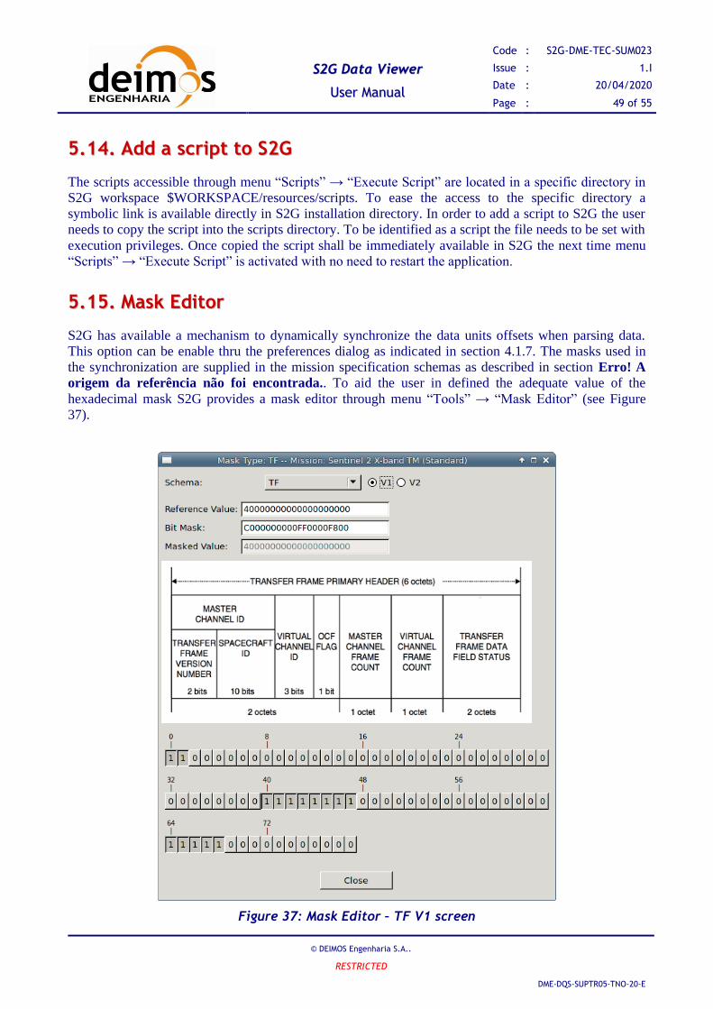
SS22GG DDaattaa VViieewweerr
UUsseerr MMaannuuaall
Code : S2G-DME-TEC-SUM023
Issue : 1.I
Date : 20/04/2020
Page : 49 of 55
© DEIMOS Engenharia S.A..
RESTRICTED
DME-DQS-SUPTR05-TNO-20-E
55..1144.. AAdddd aa ssccrriipptt ttoo SS22GG
The scripts accessible through menu “Scripts” → “Execute Script” are located in a specific directory in
S2G workspace $WORKSPACE/resources/scripts. To ease the access to the specific directory a
symbolic link is available directly in S2G installation directory. In order to add a script to S2G the user
needs to copy the script into the scripts directory. To be identified as a script the file needs to be set with
execution privileges. Once copied the script shall be immediately available in S2G the next time menu
“Scripts” → “Execute Script” is activated with no need to restart the application.
55..1155.. MMaasskk EEddiittoorr
S2G has available a mechanism to dynamically synchronize the data units offsets when parsing data.
This option can be enable thru the preferences dialog as indicated in section 4.1.7. The masks used in
the synchronization are supplied in the mission specification schemas as described in section Erro! A
origem da referência não foi encontrada.. To aid the user in defined the adequate value of the
hexadecimal mask S2G provides a mask editor through menu “Tools” → “Mask Editor” (see Figure
37).
Figure 37: Mask Editor – TF V1 screen

SS22GG DDaattaa VViieewweerr
UUsseerr MMaannuuaall
Code : S2G-DME-TEC-SUM023
Issue : 1.I
Date : 20/04/2020
Page : 50 of 55
© DEIMOS Engenharia S.A..
RESTRICTED
DME-DQS-SUPTR05-TNO-20-E
The Mask Editor is composed of the following elements:
➢ A Schema Type selection (CADU, TF, ISP). For TF selection the user can also select among V1
and V2 format;
➢ A ‘Reference Value’ hexadecimal field, which the user can edit to represent a typical value of the
data to be synchronized;
➢ A ‘Bit Mask’ hexadecimal field, which corresponds to the mask to apply to the data;
➢ A ‘Masked Value’ field, showing the application of the mask to the reference value;
➢ A figure summarizing the structure of the selected schema type header;
➢ A set of bit buttons, which the user can toggle to edit the bit mask on a bit by bit level.

SS22GG DDaattaa VViieewweerr
UUsseerr MMaannuuaall
Code : S2G-DME-TEC-SUM023
Issue : 1.I
Date : 20/04/2020
Page : 51 of 55
© DEIMOS Engenharia S.A..
RESTRICTED
DME-DQS-SUPTR05-TNO-20-E
This page intentionally left blank

SS22GG DDaattaa VViieewweerr
UUsseerr MMaannuuaall
Code : S2G-DME-TEC-SUM023
Issue : 1.I
Date : 20/04/2020
Page : 52 of 55
© DEIMOS Engenharia S.A..
RESTRICTED
DME-DQS-SUPTR05-TNO-20-E
66.. CCOOMMMMAANNDD LLIINNEE
66..11.. HHooww ttoo rruunn ffrroomm ccoommmmaanndd lliinnee::
S2G can be called with command line arguments to easy the opening of the S2G window GUI with a
product file loaded.
Those commands line arguments will set the mission schema, the schema type and the product file to be
loaded.
To call S2G with arguments use:
s2g -cli -schema_type “type” -mission_file “path/to/file” -product_file “path/to/file/”
Where:
1. “-cli” flag indicates whether to use command line arguments or not
2. “-schema-type” can have one of five values: Scrambled_CADU, CADU, TF, ISP, Annotated_ISP
3. “-mission_file” is the path to the mission schemas
4. “-product_file” is the path to the product file
66..22.. WWhheerree iiss tthhee ""ss22gg"" ccoommmmaanndd iinn tthhee ddiiffffeerreenntt ttaarrggeett
eennvviirroonnmmeennttss::
The "s2g" command is handled differently, depending of the target environment. Check where to find
the "s2g" command for your case:
• Mac: ./s2g.app/Contents/MacOS/s2g
• Linux: ./s2g
• Windows: ./s2g.exe
Due to behavior of Windows Command Line, when executing an ‘.exe’ the command line will not wait
to finish its execution. Due to this behavior, messages sent to standard output (like validation of
command line arguments), will not be shown. It is recommended to add “| more” at the end of the
command. Example command: “s2g.exe -cli -schema_type "type" -mission_file "path/to/file" -
product_file "path/to/file | more"

SS22GG DDaattaa VViieewweerr
UUsseerr MMaannuuaall
Code : S2G-DME-TEC-SUM023
Issue : 1.I
Date : 20/04/2020
Page : 53 of 55
© DEIMOS Engenharia S.A..
RESTRICTED
DME-DQS-SUPTR05-TNO-20-E
77.. TTRROOUUBBLLEESSHHOOOOTTIINNGG
77..11.. PPrroobblleemm:: UUnnaabbllee ttoo ffiinndd CCAADDUU ssyynncc mmaarrkkeerr
The first step performed when opening a CADU file is to find the sync marker to calculate the offset of
the beginning of the first CADU stored in the file. The error dialog in Figure 38 is displayed if the tool
is unable to find the sync marker.
To correct this issue, consider:
➢ verifying that the selected file does in fact contain CADU packets
➢ verifying that the value for the sync marker is correctly specified in the mission data schemas (refer
to section 5.13 for details on how to customize mission data schemas)
Figure 38: Error dialog (Unable to find CADU Sync Marker).
77..22.. PPrroobblleemm:: UUnnaabbllee ttoo llooaadd mmiissssiioonn ddeeffiinniittiioonn sscchheemmaa
When a data file is open, the tool interprets the file contents according to the mission data schema. If a
syntax problem is found while loading the schema, an error dialog is shown indicating the problem’s
cause – see example in Figure 39.
This issue can be corrected by editing the XSD schema file indicated in the error dialog.
Figure 39: Error dialog (Unable to load mission definition schema).
SS22GG DDaattaa VViieewweerr
UUsseerr MMaannuuaall
Code : S2G-DME-TEC-SUM023
Issue : 1.I
Date : 20/04/2020
Page : 54 of 55
© DEIMOS Engenharia S.A..
RESTRICTED
DME-DQS-SUPTR05-TNO-20-E
77..33.. PPrroobblleemm:: CCoorrrruupptteedd wwoorrkkssppaaccee
The contents of the workspace created automatically when S2G is launched for the first time are not
expected to be edited by the user. However, if the workspace content becomes corrupted by some
external reason, the user can revert to the default by proceeding as follows:
1. Delete the workspace directory.
2. Restart the application.
Note: Upon restart, S2G rebuilds the workspace contents with default values.
77..44.. PPrroobblleemm:: SSyynncchhrroonniizzaattiioonn rreellaatteedd iissssuueess
While opening a file, S2G may try (if data unit offset synchronisation is enabled in the Preferences) to
match the bit patterns (if any) defined by the mission definition file (see section 4.2.1 for details) in
order to check for data units synchronization. To optimize the loading operation the synchronization
result is stored in a cache for future use when re-loading the same file.
In case the cached data becomes inadequate for the originally loaded data the application may show
some misbehaviour: the quality report signals errors while looking at the data there is no underlying
problem or even several executions of the quality report result in different set of errors.
This issue can be corrected by clearing the synchronization offset cache (refer to section 4.1.7, Figure
18)

SS22GG DDaattaa VViieewweerr
UUsseerr MMaannuuaall
Code : S2G-DME-TEC-SUM023
Issue : 1.I
Date : 20/04/2020
Page : 55 of 55
© DEIMOS Engenharia S.A..
RESTRICTED
DME-DQS-SUPTR05-TNO-20-E
End of Document


![Take-3000-Installationsanleitung-Spiegelschrank-7 · A [mm] 500 mm 600 mm 800 mm 1.000 mm 1.200 mm Ø6mm B [mm] 400 mm 500 mm 700 mm 900 mm 1.100 mm](https://img.dokumen.tips/doc/110x75/5e1a362e3bfd1320474f235f/take-3000-installationsanleitung-spiegelschrank-7-a-mm-500-mm-600-mm-800-mm-1000.jpg)


