Embed Size (px)
Citation preview
S24SP series 60W Single Output DCDC Converter
DS_S24SP_60W_01052017 E-mail dcdcdeltawwcom
httpwwwdeltawwcomdcdc P1
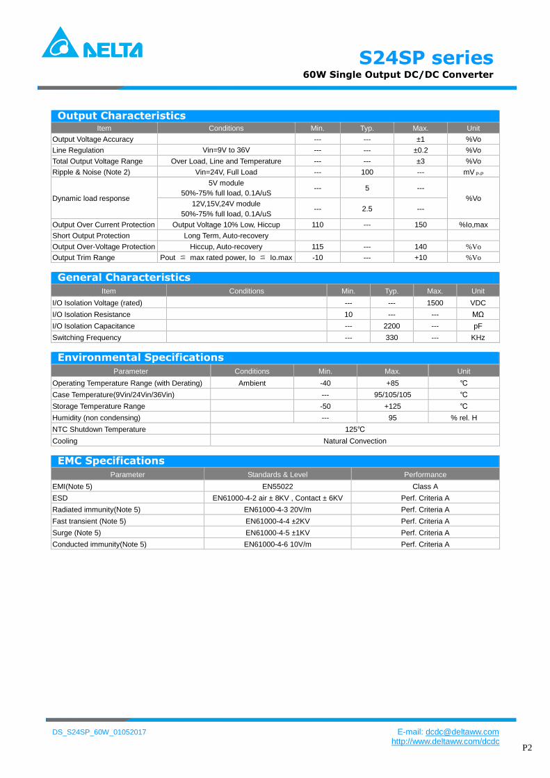
Model List Model
Number
Input
Voltage
(Range)
Output
Voltage
Output Current Input Current
(typ input voltage)
Load
Regulation
Maxcapacitive Load
(Cap ESRgt=10mohmFull
load5overshoot of Vout
at startup)
Efficiency
(typ)
Max Min Max Load No Load Max Load
VDC VDC mA mA mA(typ) mA(typ) mV(max) uF
S24SP05012 24
(9 ~ 36)
5V 12000 0 2700 70 plusmn25 20000 924
S24SP12005 12V 5000 0 2695 60 plusmn60 6000 928
S24SP15004 15V 4000 0 2680 60 plusmn75 4000 933
S24SP24003 24V 2500 0 2688 40 plusmn120 2000 93
Input Characteristics Item Model Min Typ Max Unit
Input Surge Voltage (100 msec) All Models --- --- 50 VDC
Input Turn-On Voltage Threshold All Models 8 85 9 VDC
Input Turn-Off Voltage Threshold All Models 7 75 8 VDC
Input Under-Voltage Lockout Hysteresis All Models 04 1 17 VDC
Off-Converter Input Current All ModelsVin=24V --- 10 --- mA
Input reflected ripple current All Modelswith 12uH 20MHz --- 15 30 mA
Reverse Polarity Input Current All Models --- --- 05 A
ONOFF Control Logic High All Models 24 --- 10 VDC
ONOFF Control Logic Low All Models -07 --- 08 VDC
Input Filter All Models Internal LC Filter
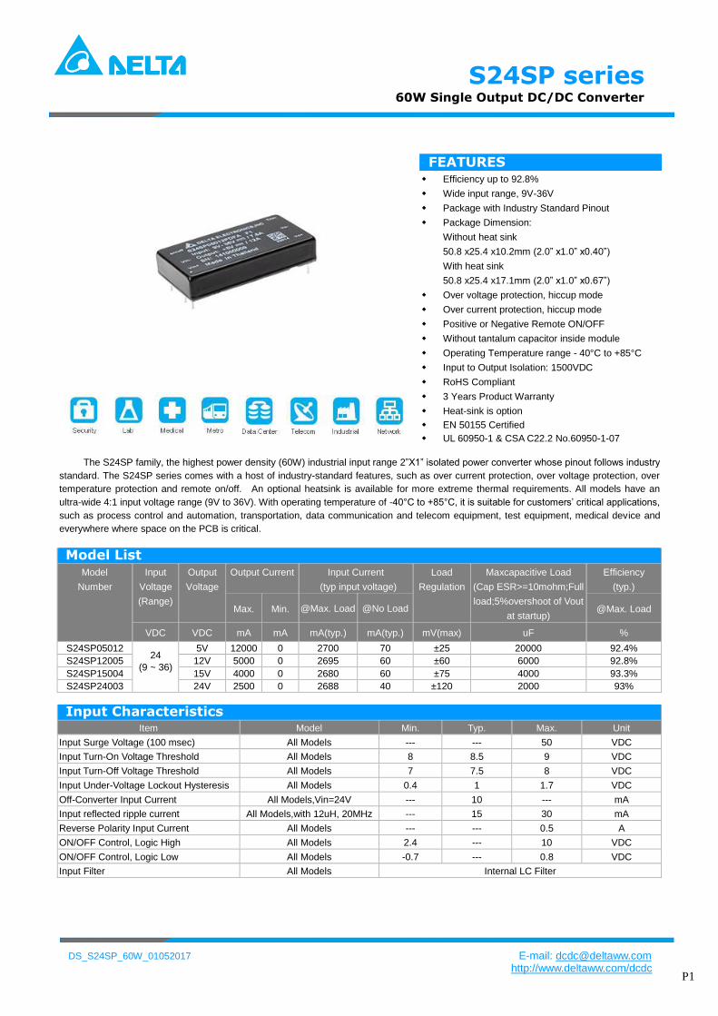
FEATURES
Efficiency up to 928
Wide input range 9V-36V
Package with Industry Standard Pinout
Package Dimension
Without heat sink
508 x254 x102mm (20rdquo x10rdquo x040rdquo)
With heat sink
508 x254 x171mm (20rdquo x10rdquo x067rdquo)
Over voltage protection hiccup mode
Over current protection hiccup mode
Positive or Negative Remote ONOFF
Without tantalum capacitor inside module
Operating Temperature range - 40degC to +85degC
Input to Output Isolation 1500VDC
RoHS Compliant
3 Years Product Warranty
Heat-sink is option
EN 50155 Certified
UL 60950-1 amp CSA C222 No60950-1-07
The S24SP family the highest power density (60W) industrial input range 2rdquoX1rdquo isolated power converter whose pinout follows industry
standard The S24SP series comes with a host of industry-standard features such as over current protection over voltage protection over
temperature protection and remote onoff An optional heatsink is available for more extreme thermal requirements All models have an
ultra-wide 41 input voltage range (9V to 36V) With operating temperature of -40degC to +85degC it is suitable for customersrsquo critical applications
such as process control and automation transportation data communication and telecom equipment test equipment medical device and
everywhere where space on the PCB is critical
S24SP series 60W Single Output DCDC Converter
DS_S24SP_60W_01052017 E-mail dcdcdeltawwcom
httpwwwdeltawwcomdcdc P2
Output Characteristics
Item Conditions Min Typ Max Unit
Output Voltage Accuracy --- --- plusmn1 Vo
Line Regulation Vin=9V to 36V --- --- plusmn02 Vo
Total Output Voltage Range Over Load Line and Temperature --- --- plusmn3 Vo
Ripple amp Noise (Note 2) Vin=24V Full Load --- 100 --- mV P-P
Dynamic load response
5V module
50-75 full load 01AuS --- 5 ---
Vo 12V15V24V module
50-75 full load 01AuS --- 25 ---
Output Over Current Protection Output Voltage 10 Low Hiccup 110 --- 150 Iomax
Short Output Protection Long Term Auto-recovery
Output Over-Voltage Protection Hiccup Auto-recovery 115 --- 140 Vo
Output Trim Range Pout ≦ max rated power Io ≦ Iomax -10 --- +10 Vo
General Characteristics
Item Conditions Min Typ Max Unit
IO Isolation Voltage (rated) --- --- 1500 VDC
IO Isolation Resistance 10 --- --- MΩ
IO Isolation Capacitance --- 2200 --- pF
Switching Frequency --- 330 --- KHz
Environmental Specifications
Parameter Conditions Min Max Unit
Operating Temperature Range (with Derating) Ambient -40 +85
Case Temperature(9Vin24Vin36Vin) --- 95105105
Storage Temperature Range -50 +125
Humidity (non condensing) --- 95 rel H
NTC Shutdown Temperature 125
Cooling Natural Convection
EMC Specifications
Parameter Standards amp Level Performance
EMI(Note 5) EN55022 Class A
ESD EN61000-4-2 air plusmn 8KV Contact plusmn 6KV Perf Criteria A
Radiated immunity(Note 5) EN61000-4-3 20Vm Perf Criteria A
Fast transient (Note 5) EN61000-4-4 plusmn2KV Perf Criteria A
Surge (Note 5) EN61000-4-5 plusmn1KV Perf Criteria A
Conducted immunity(Note 5) EN61000-4-6 10Vm Perf Criteria A
S24SP series 60W Single Output DCDC Converter
DS_S24SP_60W_01052017 E-mail dcdcdeltawwcom
httpwwwdeltawwcomdcdc P3
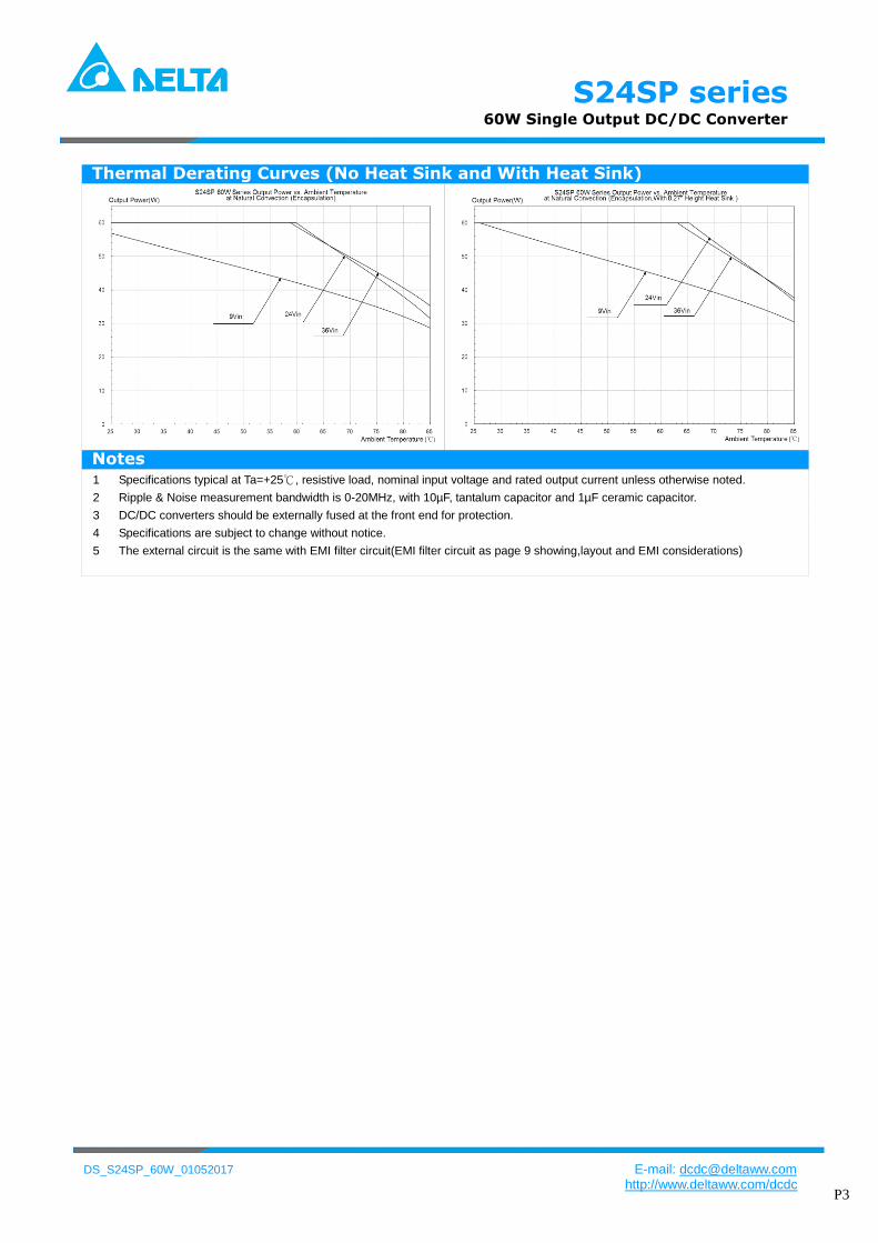
Thermal Derating Curves (No Heat Sink and With Heat Sink)
Notes 1 Specifications typical at Ta=+25 resistive load nominal input voltage and rated output current unless otherwise noted
2 Ripple amp Noise measurement bandwidth is 0-20MHz with 10microF tantalum capacitor and 1microF ceramic capacitor
DCDC converters should be externally fused at the front end for protection 3rlmrlm
4 Specifications are subject to change without notice
5 The external circuit is the same with EMI filter circuit(EMI filter circuit as page 9 showinglayout and EMI considerations)
S24SP series 60W Single Output DCDC Converter
DS_S24SP_60W_01052017 E-mail dcdcdeltawwcom
httpwwwdeltawwcomdcdc P4
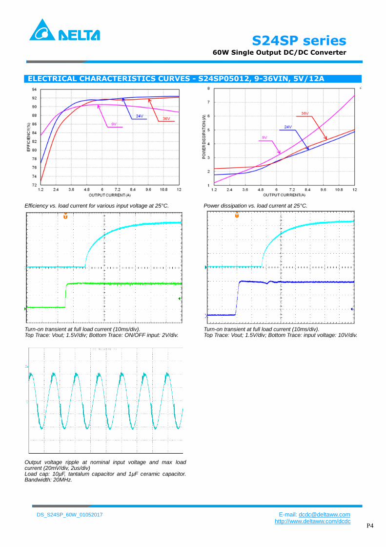
ELECTRICAL CHARACTERISTICS CURVES - S24SP05012 9-36VIN 5V12A
Efficiency vs load current for various input voltage at 25degC Power dissipation vs load current at 25degC
Turn-on transient at full load current (10msdiv) Top Trace Vout 15Vdiv Bottom Trace ONOFF input 2Vdiv
Turn-on transient at full load current (10msdiv) Top Trace Vout 15Vdiv Bottom Trace input voltage 10Vdiv
Output voltage ripple at nominal input voltage and max load current (20mVdiv 2usdiv) Load cap 10microF tantalum capacitor and 1microF ceramic capacitor Bandwidth 20MHz
S24SP series 60W Single Output DCDC Converter
DS_S24SP_60W_01052017 E-mail dcdcdeltawwcom
httpwwwdeltawwcomdcdc P5
ELECTRICAL CHARACTERISTICS CURVES - S24SP12005 9-36VIN 12V5A
74
76
78
80
82
84
86
88
90
92
94
05 1 15 2 25 3 35 4 45 5
EF
FIC
IEN
CY
()
OUTPUT CURRENT(A)
24Vin 36Vin
9Vin
Efficiency vs load current for various input voltage at 25degC Power dissipation vs load current at 25degC
Turn-on transient at full load current (20msdiv) Top Trace Vout 5Vdiv Bottom Trace ONOFF input 5Vdiv
Turn-on transient at full load current (20msdiv) Top Trace Vout 3Vdiv Bottom Trace input voltage 30Vdiv
Output voltage ripple at nominal input voltage and max load current (20mVdiv 2usdiv) Load cap 10microF tantalum capacitor and 1microF ceramic capacitor Bandwidth 20MHz
0
0
0
0
0
S24SP series 60W Single Output DCDC Converter
DS_S24SP_60W_01052017 E-mail dcdcdeltawwcom
httpwwwdeltawwcomdcdc P6
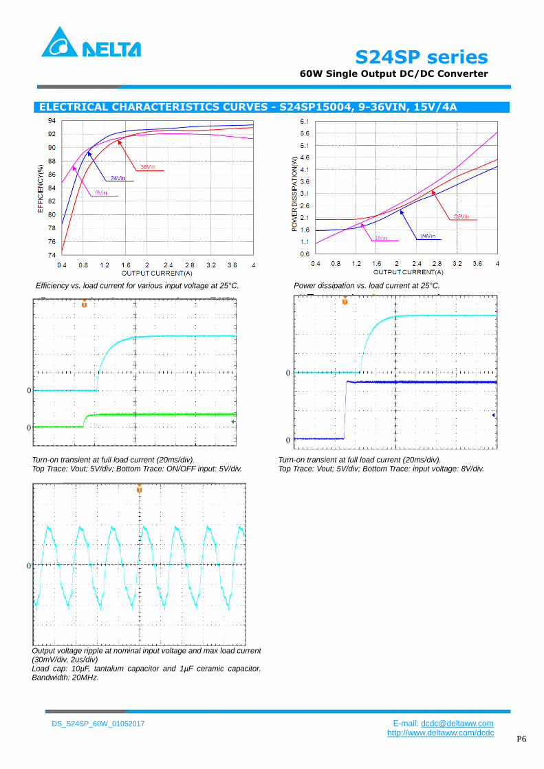
ELECTRICAL CHARACTERISTICS CURVES - S24SP15004 9-36VIN 15V4A
Efficiency vs load current for various input voltage at 25degC Power dissipation vs load current at 25degC
Turn-on transient at full load current (20msdiv) Top Trace Vout 5Vdiv Bottom Trace ONOFF input 5Vdiv
Turn-on transient at full load current (20msdiv) Top Trace Vout 5Vdiv Bottom Trace input voltage 8Vdiv
Output voltage ripple at nominal input voltage and max load current (30mVdiv 2usdiv) Load cap 10microF tantalum capacitor and 1microF ceramic capacitor Bandwidth 20MHz
0
0
0
0
0
S24SP series 60W Single Output DCDC Converter
DS_S24SP_60W_01052017 E-mail dcdcdeltawwcom
httpwwwdeltawwcomdcdc P7
ELECTRICAL CHARACTERISTICS CURVES - S24SP24003 9-36VIN 24V25A
Efficiency vs load current for various input voltage at 25degC Power dissipation vs load current at 25degC
Turn-on transient at full load current (10msdiv) Top Trace Vout 5Vdiv Bottom Trace ONOFF input 1Vdiv
Turn-on transient at full load current (10msdiv) Top Trace Vout 5Vdiv Bottom Trace input voltage 10Vdiv
Output voltage ripple at nominal input voltage and max load current (20mVdiv 2usdiv) Load cap 10microF tantalum capacitor and 1microF ceramic capacitor Bandwidth 20MHz
0 0
0
S24SP series 60W Single Output DCDC Converter
DS_S24SP_60W_01052017 E-mail dcdcdeltawwcom
httpwwwdeltawwcomdcdc P8
DESIGN CONSIDERATIONS Input Source Impedance The impedance of the input source connecting to the DCDC power modules will interact with the modules and affect the stability A low ac-impedance input source is recommended If the source inductance is more than a few μH we advise a 100μF electrolytic capacitor mounted close to the input of the module to improve the stability
Input Reflected Ripple Current
Vin+
Vin-
is ic
100uF
ESR=02 ohm
25oC 100KHz
Cs 220uF
+ +
Vin+
Vin-
is ic
100uF
ESR=02 ohm
25oC 100KHz
Cs 220uF
+ +
is ic
100uF
ESR=02 ohm
25oC 100KHz
Cs 220uF
++ ++
Test set-up diagram showing measurement points for Input Terminal Ripple Current and Input Reflected Ripple Current Measured input reflected-ripple current with a simulated source Inductance (LTEST) of 12 μH Capacitor Cs offset possible battery impedance
Input Terminal Ripple Current ic at full rated output current and nominal input voltage with 12microH source impedance and 100microF electrolytic capacitor (250 mAdiv 4usdiv)
Input reflected ripple current is through a 12microH source inductor at nominal input voltage and rated load current (25 mAdiv 4usdiv)
Output Ripple Noise
Output voltage ripple test setup Load capacitance 1microF ceramic capacitor and 10microF tantalum capacitor Bandwidth 20 MHz Scope measurements should be made using a BNC cable (length shorter than 20 inches) Position the load between 51 mm to 76 mm (2 inches to 3 inches) from the module
S24SP series 60W Single Output DCDC Converter
DS_S24SP_60W_01052017 E-mail dcdcdeltawwcom
httpwwwdeltawwcomdcdc P9
DESIGN CONSIDERATIONS Layout and EMI considerations Deltarsquos DCDC power modules are designed to operate in a wide variety of systems and applications For design assistance with EMC compliance and related PWB layout issues please contact Deltarsquos technical support team An external input filter module is available for easier EMC compliance design Below is the reference design for an input filter to pass EN55022 (VDE0878) class A (both q peak and average)
EMI filter circuit
Cin=100uF50VNippon chemi-conESR 85 mohm
L1=47uHPCMC063T-4R7MN
C1=68uF50V1812MLCC
CY1=68nF2KV1210MLCC
Test Result
1 MHz 10 MHz1501 kHz 30 MHz
100
200
300
400
500
600
700
00
800
dBμV
Limits
55022MAV
55022MQP
Transducer
8130
Traces
PK+
AV
At T = +25C Typical input voltage and full load
Recommended PCB Layout
It is suggested to use multiple layers PCB and large
size copper on system board which connects to pins of
module that can achieve better thermal performance
FEATURES DESCRIPTIONS Over-Current Protection
The modules include an internal output over-current protection circuit which will endure current limiting for an unlimited duration during output overload If the output current exceeds the OCP set point the modules will shut down (hiccup mode) The modules will try to restart after shutdown If the overload condition still exists the module will shut down again This restart trial will continue until the overload condition is corrected
Over-Voltage Protection
The modules include an internal output over-voltage protection circuit which monitors the voltage on the output terminals If this voltage exceeds the over-voltage set point the modules will shut down and then restart after a hiccup-time (hiccup mode) If latch mode is needed please contact with Delta
Over-Temperature Protection
The over-temperature protection consists of circuitry that provides protection from thermal damage If the temperature exceeds the over-temperature threshold the module will shut downThe module will restart after the temperature is within specification
Remote OnOff
The remote onoff feature on the module can be either negative or positive logic depend on the part number options on the last page For Negative logic version turns the module on
during a external logic low and off during a logic high If the remote onoff feature is not used please short the onoff pin to Vi (-)
For Postive logic version turns the modules on during a external logic high and off during a logic low If the remote onoff feature is not used please leave the onoff pin to floating
Remote onoff can be controlled by an external switch between the onoff terminal and the Vi (-) terminal The switch can be an open collector or open drain
S24SP series 60W Single Output DCDC Converter
DS_S24SP_60W_01052017 E-mail dcdcdeltawwcom
httpwwwdeltawwcomdcdc P10
For 15V signle output (Kohm)
For 24V single output (Kohm)
For example When need trim up to 52V then the external resistor should be 952Kohm between trim pin and Vout- pin When need trim down to 49V then the external resistor should be 2912Kohm between trim pin and Vout+ pin
THERMAL CONSIDERATIONS
Thermal de-rating curve is a standard for customer to make thermal evaluation and make sure the modulersquos components are operated under allowed temperature The modulersquos cooling condition is natural convection In thermal de-rating curve if we know the modulersquos input voltage and output power we can find the allowed maximum ambient temperature
The modulersquos case temperature is a reference to make thermal evaluation If the case temperature exceed the allowed maximum value the moldule may probably have thermal issue
Remote onoff implementation Output Voltage Adjustment (TRIM) Only single output modules have output adjust function To increase the output voltage set point connect an external resistor between the TRIM pin and the Vout(-) To decrease the output voltage set point connect an external resistor between the TRIM pin and the Vout(+) The maximum adjust range is plusmn10 the TRIM pin should be left open if this feature is not used For 5V single output (Kohm)
For 12V single output (Kohm)
S24SP series 60W Single Output DCDC Converter
DS_S24SP_60W_01052017 E-mail dcdcdeltawwcom
httpwwwdeltawwcomdcdc P11
Mechanical Drawing(without heat sink) Mechanical Dimensions Pin Connections
Pin Function
1 Vin+
2 Vin-
3 Onoff
4 Trim
5 Vout-
6 Vout+
Physical outline
Case Size 508254102(20rdquo10rdquo04rdquo)
Case material Al alloy anodize black
Baseplate material Non-conductive FR-4
Pin material Brass finish Matte Tin
plating and Nickel under plating Pin length refer part numbering system
Weight 34grams
All dimensions in mm (inches)
Tolerance XXplusmn05 (XXXplusmn002)
XXXplusmn025 ( XXXXplusmn0010)
Pins Diameter plusmn010(plusmn0004)
Mechanical Drawing(with heat sink) Mechanical Dimensions Physical Outline
1 Heat sink
Material Al-6063
Finish anodize black
Weight 103grams
2 Model weight 46grams
All dimensions in mm (inches)
Tolerance XXplusmn05 (XXXplusmn002)
XXXplusmn025 ( XXXXplusmn0010)
Note
1 add heat sink to help heat dissipation and increase reliability of convert operating at high ambient temperature
2 please refer derating curve while upgrate the operating temperature of converter
S24SP series 60W Single Output DCDC Converter
DS_S24SP_60W_01052017 E-mail dcdcdeltawwcom
httpwwwdeltawwcomdcdc P12
Application notice For modules with through-hole pins they are intended for wave soldering assembly onto system boards
please do not subject such modules through reflow temperature profile
Recommended layout refer below
S24SP series 60W Single Output DCDC Converter
DS_S24SP_60W_01052017 E-mail dcdcdeltawwcom
httpwwwdeltawwcomdcdc P13
Part Numbering System
S 24 S P 050 12 P D F A
Form
factor
Input
voltage
Number
of output
Product
series
Output
voltage
Output
current Onoff logic
Pin
length Option Code
S 24 ndash 9~36V S - Single
P - Series
Number
050 ndash 5V 12 ndash 12A N ndash Negative
P ndash Positive
D - 024rdquo
T - 022rdquo
R - 017rdquo
F - RoHS 66
(Lead Free)
A ndash Standard
(with metal
case)
H ndash With heat
sink
CONTACT wwwdeltawwcomdcdc Email dcdcdeltawwcom
USA
Telephone East Coast 978-656-3993 West Coast 510-668-5100 Fax (978) 656 3964
Europe
Phone +31-20-655-0967 Fax +31-20-655-0999
Asia amp the rest of world
Telephone +886 3 4526107 ext 6220~6224 Fax +886 3 4513485
WARRANTY
Delta offers a three (3) years limited warranty Complete warranty information is listed on our web site or is available upon
request from Delta
Information furnished by Delta is believed to be accurate and reliable However no responsibility is assumed by Delta for
its use nor for any infringements of patents or other rights of third parties which may result from its use No license is
granted by implication or otherwise under any patent or patent rights of Delta Delta reserves the right to revise these
specifications at any time without notice
S24SP series 60W Single Output DCDC Converter
DS_S24SP_60W_01052017 E-mail dcdcdeltawwcom
httpwwwdeltawwcomdcdc P2
Output Characteristics
Item Conditions Min Typ Max Unit
Output Voltage Accuracy --- --- plusmn1 Vo
Line Regulation Vin=9V to 36V --- --- plusmn02 Vo
Total Output Voltage Range Over Load Line and Temperature --- --- plusmn3 Vo
Ripple amp Noise (Note 2) Vin=24V Full Load --- 100 --- mV P-P
Dynamic load response
5V module
50-75 full load 01AuS --- 5 ---
Vo 12V15V24V module
50-75 full load 01AuS --- 25 ---
Output Over Current Protection Output Voltage 10 Low Hiccup 110 --- 150 Iomax
Short Output Protection Long Term Auto-recovery
Output Over-Voltage Protection Hiccup Auto-recovery 115 --- 140 Vo
Output Trim Range Pout ≦ max rated power Io ≦ Iomax -10 --- +10 Vo
General Characteristics
Item Conditions Min Typ Max Unit
IO Isolation Voltage (rated) --- --- 1500 VDC
IO Isolation Resistance 10 --- --- MΩ
IO Isolation Capacitance --- 2200 --- pF
Switching Frequency --- 330 --- KHz
Environmental Specifications
Parameter Conditions Min Max Unit
Operating Temperature Range (with Derating) Ambient -40 +85
Case Temperature(9Vin24Vin36Vin) --- 95105105
Storage Temperature Range -50 +125
Humidity (non condensing) --- 95 rel H
NTC Shutdown Temperature 125
Cooling Natural Convection
EMC Specifications
Parameter Standards amp Level Performance
EMI(Note 5) EN55022 Class A
ESD EN61000-4-2 air plusmn 8KV Contact plusmn 6KV Perf Criteria A
Radiated immunity(Note 5) EN61000-4-3 20Vm Perf Criteria A
Fast transient (Note 5) EN61000-4-4 plusmn2KV Perf Criteria A
Surge (Note 5) EN61000-4-5 plusmn1KV Perf Criteria A
Conducted immunity(Note 5) EN61000-4-6 10Vm Perf Criteria A
S24SP series 60W Single Output DCDC Converter
DS_S24SP_60W_01052017 E-mail dcdcdeltawwcom
httpwwwdeltawwcomdcdc P3
Thermal Derating Curves (No Heat Sink and With Heat Sink)
Notes 1 Specifications typical at Ta=+25 resistive load nominal input voltage and rated output current unless otherwise noted
2 Ripple amp Noise measurement bandwidth is 0-20MHz with 10microF tantalum capacitor and 1microF ceramic capacitor
DCDC converters should be externally fused at the front end for protection 3rlmrlm
4 Specifications are subject to change without notice
5 The external circuit is the same with EMI filter circuit(EMI filter circuit as page 9 showinglayout and EMI considerations)
S24SP series 60W Single Output DCDC Converter
DS_S24SP_60W_01052017 E-mail dcdcdeltawwcom
httpwwwdeltawwcomdcdc P4
ELECTRICAL CHARACTERISTICS CURVES - S24SP05012 9-36VIN 5V12A
Efficiency vs load current for various input voltage at 25degC Power dissipation vs load current at 25degC
Turn-on transient at full load current (10msdiv) Top Trace Vout 15Vdiv Bottom Trace ONOFF input 2Vdiv
Turn-on transient at full load current (10msdiv) Top Trace Vout 15Vdiv Bottom Trace input voltage 10Vdiv
Output voltage ripple at nominal input voltage and max load current (20mVdiv 2usdiv) Load cap 10microF tantalum capacitor and 1microF ceramic capacitor Bandwidth 20MHz
S24SP series 60W Single Output DCDC Converter
DS_S24SP_60W_01052017 E-mail dcdcdeltawwcom
httpwwwdeltawwcomdcdc P5
ELECTRICAL CHARACTERISTICS CURVES - S24SP12005 9-36VIN 12V5A
74
76
78
80
82
84
86
88
90
92
94
05 1 15 2 25 3 35 4 45 5
EF
FIC
IEN
CY
()
OUTPUT CURRENT(A)
24Vin 36Vin
9Vin
Efficiency vs load current for various input voltage at 25degC Power dissipation vs load current at 25degC
Turn-on transient at full load current (20msdiv) Top Trace Vout 5Vdiv Bottom Trace ONOFF input 5Vdiv
Turn-on transient at full load current (20msdiv) Top Trace Vout 3Vdiv Bottom Trace input voltage 30Vdiv
Output voltage ripple at nominal input voltage and max load current (20mVdiv 2usdiv) Load cap 10microF tantalum capacitor and 1microF ceramic capacitor Bandwidth 20MHz
0
0
0
0
0
S24SP series 60W Single Output DCDC Converter
DS_S24SP_60W_01052017 E-mail dcdcdeltawwcom
httpwwwdeltawwcomdcdc P6
ELECTRICAL CHARACTERISTICS CURVES - S24SP15004 9-36VIN 15V4A
Efficiency vs load current for various input voltage at 25degC Power dissipation vs load current at 25degC
Turn-on transient at full load current (20msdiv) Top Trace Vout 5Vdiv Bottom Trace ONOFF input 5Vdiv
Turn-on transient at full load current (20msdiv) Top Trace Vout 5Vdiv Bottom Trace input voltage 8Vdiv
Output voltage ripple at nominal input voltage and max load current (30mVdiv 2usdiv) Load cap 10microF tantalum capacitor and 1microF ceramic capacitor Bandwidth 20MHz
0
0
0
0
0
S24SP series 60W Single Output DCDC Converter
DS_S24SP_60W_01052017 E-mail dcdcdeltawwcom
httpwwwdeltawwcomdcdc P7
ELECTRICAL CHARACTERISTICS CURVES - S24SP24003 9-36VIN 24V25A
Efficiency vs load current for various input voltage at 25degC Power dissipation vs load current at 25degC
Turn-on transient at full load current (10msdiv) Top Trace Vout 5Vdiv Bottom Trace ONOFF input 1Vdiv
Turn-on transient at full load current (10msdiv) Top Trace Vout 5Vdiv Bottom Trace input voltage 10Vdiv
Output voltage ripple at nominal input voltage and max load current (20mVdiv 2usdiv) Load cap 10microF tantalum capacitor and 1microF ceramic capacitor Bandwidth 20MHz
0 0
0
S24SP series 60W Single Output DCDC Converter
DS_S24SP_60W_01052017 E-mail dcdcdeltawwcom
httpwwwdeltawwcomdcdc P8
DESIGN CONSIDERATIONS Input Source Impedance The impedance of the input source connecting to the DCDC power modules will interact with the modules and affect the stability A low ac-impedance input source is recommended If the source inductance is more than a few μH we advise a 100μF electrolytic capacitor mounted close to the input of the module to improve the stability
Input Reflected Ripple Current
Vin+
Vin-
is ic
100uF
ESR=02 ohm
25oC 100KHz
Cs 220uF
+ +
Vin+
Vin-
is ic
100uF
ESR=02 ohm
25oC 100KHz
Cs 220uF
+ +
is ic
100uF
ESR=02 ohm
25oC 100KHz
Cs 220uF
++ ++
Test set-up diagram showing measurement points for Input Terminal Ripple Current and Input Reflected Ripple Current Measured input reflected-ripple current with a simulated source Inductance (LTEST) of 12 μH Capacitor Cs offset possible battery impedance
Input Terminal Ripple Current ic at full rated output current and nominal input voltage with 12microH source impedance and 100microF electrolytic capacitor (250 mAdiv 4usdiv)
Input reflected ripple current is through a 12microH source inductor at nominal input voltage and rated load current (25 mAdiv 4usdiv)
Output Ripple Noise
Output voltage ripple test setup Load capacitance 1microF ceramic capacitor and 10microF tantalum capacitor Bandwidth 20 MHz Scope measurements should be made using a BNC cable (length shorter than 20 inches) Position the load between 51 mm to 76 mm (2 inches to 3 inches) from the module
S24SP series 60W Single Output DCDC Converter
DS_S24SP_60W_01052017 E-mail dcdcdeltawwcom
httpwwwdeltawwcomdcdc P9
DESIGN CONSIDERATIONS Layout and EMI considerations Deltarsquos DCDC power modules are designed to operate in a wide variety of systems and applications For design assistance with EMC compliance and related PWB layout issues please contact Deltarsquos technical support team An external input filter module is available for easier EMC compliance design Below is the reference design for an input filter to pass EN55022 (VDE0878) class A (both q peak and average)
EMI filter circuit
Cin=100uF50VNippon chemi-conESR 85 mohm
L1=47uHPCMC063T-4R7MN
C1=68uF50V1812MLCC
CY1=68nF2KV1210MLCC
Test Result
1 MHz 10 MHz1501 kHz 30 MHz
100
200
300
400
500
600
700
00
800
dBμV
Limits
55022MAV
55022MQP
Transducer
8130
Traces
PK+
AV
At T = +25C Typical input voltage and full load
Recommended PCB Layout
It is suggested to use multiple layers PCB and large
size copper on system board which connects to pins of
module that can achieve better thermal performance
FEATURES DESCRIPTIONS Over-Current Protection
The modules include an internal output over-current protection circuit which will endure current limiting for an unlimited duration during output overload If the output current exceeds the OCP set point the modules will shut down (hiccup mode) The modules will try to restart after shutdown If the overload condition still exists the module will shut down again This restart trial will continue until the overload condition is corrected
Over-Voltage Protection
The modules include an internal output over-voltage protection circuit which monitors the voltage on the output terminals If this voltage exceeds the over-voltage set point the modules will shut down and then restart after a hiccup-time (hiccup mode) If latch mode is needed please contact with Delta
Over-Temperature Protection
The over-temperature protection consists of circuitry that provides protection from thermal damage If the temperature exceeds the over-temperature threshold the module will shut downThe module will restart after the temperature is within specification
Remote OnOff
The remote onoff feature on the module can be either negative or positive logic depend on the part number options on the last page For Negative logic version turns the module on
during a external logic low and off during a logic high If the remote onoff feature is not used please short the onoff pin to Vi (-)
For Postive logic version turns the modules on during a external logic high and off during a logic low If the remote onoff feature is not used please leave the onoff pin to floating
Remote onoff can be controlled by an external switch between the onoff terminal and the Vi (-) terminal The switch can be an open collector or open drain
S24SP series 60W Single Output DCDC Converter
DS_S24SP_60W_01052017 E-mail dcdcdeltawwcom
httpwwwdeltawwcomdcdc P10
For 15V signle output (Kohm)
For 24V single output (Kohm)
For example When need trim up to 52V then the external resistor should be 952Kohm between trim pin and Vout- pin When need trim down to 49V then the external resistor should be 2912Kohm between trim pin and Vout+ pin
THERMAL CONSIDERATIONS
Thermal de-rating curve is a standard for customer to make thermal evaluation and make sure the modulersquos components are operated under allowed temperature The modulersquos cooling condition is natural convection In thermal de-rating curve if we know the modulersquos input voltage and output power we can find the allowed maximum ambient temperature
The modulersquos case temperature is a reference to make thermal evaluation If the case temperature exceed the allowed maximum value the moldule may probably have thermal issue
Remote onoff implementation Output Voltage Adjustment (TRIM) Only single output modules have output adjust function To increase the output voltage set point connect an external resistor between the TRIM pin and the Vout(-) To decrease the output voltage set point connect an external resistor between the TRIM pin and the Vout(+) The maximum adjust range is plusmn10 the TRIM pin should be left open if this feature is not used For 5V single output (Kohm)
For 12V single output (Kohm)
S24SP series 60W Single Output DCDC Converter
DS_S24SP_60W_01052017 E-mail dcdcdeltawwcom
httpwwwdeltawwcomdcdc P11
Mechanical Drawing(without heat sink) Mechanical Dimensions Pin Connections
Pin Function
1 Vin+
2 Vin-
3 Onoff
4 Trim
5 Vout-
6 Vout+
Physical outline
Case Size 508254102(20rdquo10rdquo04rdquo)
Case material Al alloy anodize black
Baseplate material Non-conductive FR-4
Pin material Brass finish Matte Tin
plating and Nickel under plating Pin length refer part numbering system
Weight 34grams
All dimensions in mm (inches)
Tolerance XXplusmn05 (XXXplusmn002)
XXXplusmn025 ( XXXXplusmn0010)
Pins Diameter plusmn010(plusmn0004)
Mechanical Drawing(with heat sink) Mechanical Dimensions Physical Outline
1 Heat sink
Material Al-6063
Finish anodize black
Weight 103grams
2 Model weight 46grams
All dimensions in mm (inches)
Tolerance XXplusmn05 (XXXplusmn002)
XXXplusmn025 ( XXXXplusmn0010)
Note
1 add heat sink to help heat dissipation and increase reliability of convert operating at high ambient temperature
2 please refer derating curve while upgrate the operating temperature of converter
S24SP series 60W Single Output DCDC Converter
DS_S24SP_60W_01052017 E-mail dcdcdeltawwcom
httpwwwdeltawwcomdcdc P12
Application notice For modules with through-hole pins they are intended for wave soldering assembly onto system boards
please do not subject such modules through reflow temperature profile
Recommended layout refer below
S24SP series 60W Single Output DCDC Converter
DS_S24SP_60W_01052017 E-mail dcdcdeltawwcom
httpwwwdeltawwcomdcdc P13
Part Numbering System
S 24 S P 050 12 P D F A
Form
factor
Input
voltage
Number
of output
Product
series
Output
voltage
Output
current Onoff logic
Pin
length Option Code
S 24 ndash 9~36V S - Single
P - Series
Number
050 ndash 5V 12 ndash 12A N ndash Negative
P ndash Positive
D - 024rdquo
T - 022rdquo
R - 017rdquo
F - RoHS 66
(Lead Free)
A ndash Standard
(with metal
case)
H ndash With heat
sink
CONTACT wwwdeltawwcomdcdc Email dcdcdeltawwcom
USA
Telephone East Coast 978-656-3993 West Coast 510-668-5100 Fax (978) 656 3964
Europe
Phone +31-20-655-0967 Fax +31-20-655-0999
Asia amp the rest of world
Telephone +886 3 4526107 ext 6220~6224 Fax +886 3 4513485
WARRANTY
Delta offers a three (3) years limited warranty Complete warranty information is listed on our web site or is available upon
request from Delta
Information furnished by Delta is believed to be accurate and reliable However no responsibility is assumed by Delta for
its use nor for any infringements of patents or other rights of third parties which may result from its use No license is
granted by implication or otherwise under any patent or patent rights of Delta Delta reserves the right to revise these
specifications at any time without notice
S24SP series 60W Single Output DCDC Converter
DS_S24SP_60W_01052017 E-mail dcdcdeltawwcom
httpwwwdeltawwcomdcdc P4
ELECTRICAL CHARACTERISTICS CURVES - S24SP05012 9-36VIN 5V12A
Efficiency vs load current for various input voltage at 25degC Power dissipation vs load current at 25degC
Turn-on transient at full load current (10msdiv) Top Trace Vout 15Vdiv Bottom Trace ONOFF input 2Vdiv
Turn-on transient at full load current (10msdiv) Top Trace Vout 15Vdiv Bottom Trace input voltage 10Vdiv
Output voltage ripple at nominal input voltage and max load current (20mVdiv 2usdiv) Load cap 10microF tantalum capacitor and 1microF ceramic capacitor Bandwidth 20MHz
S24SP series 60W Single Output DCDC Converter
DS_S24SP_60W_01052017 E-mail dcdcdeltawwcom
httpwwwdeltawwcomdcdc P5
ELECTRICAL CHARACTERISTICS CURVES - S24SP12005 9-36VIN 12V5A
74
76
78
80
82
84
86
88
90
92
94
05 1 15 2 25 3 35 4 45 5
EF
FIC
IEN
CY
()
OUTPUT CURRENT(A)
24Vin 36Vin
9Vin
Efficiency vs load current for various input voltage at 25degC Power dissipation vs load current at 25degC
Turn-on transient at full load current (20msdiv) Top Trace Vout 5Vdiv Bottom Trace ONOFF input 5Vdiv
Turn-on transient at full load current (20msdiv) Top Trace Vout 3Vdiv Bottom Trace input voltage 30Vdiv
Output voltage ripple at nominal input voltage and max load current (20mVdiv 2usdiv) Load cap 10microF tantalum capacitor and 1microF ceramic capacitor Bandwidth 20MHz
0
0
0
0
0
S24SP series 60W Single Output DCDC Converter
DS_S24SP_60W_01052017 E-mail dcdcdeltawwcom
httpwwwdeltawwcomdcdc P6
ELECTRICAL CHARACTERISTICS CURVES - S24SP15004 9-36VIN 15V4A
Efficiency vs load current for various input voltage at 25degC Power dissipation vs load current at 25degC
Turn-on transient at full load current (20msdiv) Top Trace Vout 5Vdiv Bottom Trace ONOFF input 5Vdiv
Turn-on transient at full load current (20msdiv) Top Trace Vout 5Vdiv Bottom Trace input voltage 8Vdiv
Output voltage ripple at nominal input voltage and max load current (30mVdiv 2usdiv) Load cap 10microF tantalum capacitor and 1microF ceramic capacitor Bandwidth 20MHz
0
0
0
0
0
S24SP series 60W Single Output DCDC Converter
DS_S24SP_60W_01052017 E-mail dcdcdeltawwcom
httpwwwdeltawwcomdcdc P7
ELECTRICAL CHARACTERISTICS CURVES - S24SP24003 9-36VIN 24V25A
Efficiency vs load current for various input voltage at 25degC Power dissipation vs load current at 25degC
Turn-on transient at full load current (10msdiv) Top Trace Vout 5Vdiv Bottom Trace ONOFF input 1Vdiv
Turn-on transient at full load current (10msdiv) Top Trace Vout 5Vdiv Bottom Trace input voltage 10Vdiv
Output voltage ripple at nominal input voltage and max load current (20mVdiv 2usdiv) Load cap 10microF tantalum capacitor and 1microF ceramic capacitor Bandwidth 20MHz
0 0
0
S24SP series 60W Single Output DCDC Converter
DS_S24SP_60W_01052017 E-mail dcdcdeltawwcom
httpwwwdeltawwcomdcdc P8
DESIGN CONSIDERATIONS Input Source Impedance The impedance of the input source connecting to the DCDC power modules will interact with the modules and affect the stability A low ac-impedance input source is recommended If the source inductance is more than a few μH we advise a 100μF electrolytic capacitor mounted close to the input of the module to improve the stability
Input Reflected Ripple Current
Vin+
Vin-
is ic
100uF
ESR=02 ohm
25oC 100KHz
Cs 220uF
+ +
Vin+
Vin-
is ic
100uF
ESR=02 ohm
25oC 100KHz
Cs 220uF
+ +
is ic
100uF
ESR=02 ohm
25oC 100KHz
Cs 220uF
++ ++
Test set-up diagram showing measurement points for Input Terminal Ripple Current and Input Reflected Ripple Current Measured input reflected-ripple current with a simulated source Inductance (LTEST) of 12 μH Capacitor Cs offset possible battery impedance
Input Terminal Ripple Current ic at full rated output current and nominal input voltage with 12microH source impedance and 100microF electrolytic capacitor (250 mAdiv 4usdiv)
Input reflected ripple current is through a 12microH source inductor at nominal input voltage and rated load current (25 mAdiv 4usdiv)
Output Ripple Noise
Output voltage ripple test setup Load capacitance 1microF ceramic capacitor and 10microF tantalum capacitor Bandwidth 20 MHz Scope measurements should be made using a BNC cable (length shorter than 20 inches) Position the load between 51 mm to 76 mm (2 inches to 3 inches) from the module
S24SP series 60W Single Output DCDC Converter
DS_S24SP_60W_01052017 E-mail dcdcdeltawwcom
httpwwwdeltawwcomdcdc P9
DESIGN CONSIDERATIONS Layout and EMI considerations Deltarsquos DCDC power modules are designed to operate in a wide variety of systems and applications For design assistance with EMC compliance and related PWB layout issues please contact Deltarsquos technical support team An external input filter module is available for easier EMC compliance design Below is the reference design for an input filter to pass EN55022 (VDE0878) class A (both q peak and average)
EMI filter circuit
Cin=100uF50VNippon chemi-conESR 85 mohm
L1=47uHPCMC063T-4R7MN
C1=68uF50V1812MLCC
CY1=68nF2KV1210MLCC
Test Result
1 MHz 10 MHz1501 kHz 30 MHz
100
200
300
400
500
600
700
00
800
dBμV
Limits
55022MAV
55022MQP
Transducer
8130
Traces
PK+
AV
At T = +25C Typical input voltage and full load
Recommended PCB Layout
It is suggested to use multiple layers PCB and large
size copper on system board which connects to pins of
module that can achieve better thermal performance
FEATURES DESCRIPTIONS Over-Current Protection
The modules include an internal output over-current protection circuit which will endure current limiting for an unlimited duration during output overload If the output current exceeds the OCP set point the modules will shut down (hiccup mode) The modules will try to restart after shutdown If the overload condition still exists the module will shut down again This restart trial will continue until the overload condition is corrected
Over-Voltage Protection
The modules include an internal output over-voltage protection circuit which monitors the voltage on the output terminals If this voltage exceeds the over-voltage set point the modules will shut down and then restart after a hiccup-time (hiccup mode) If latch mode is needed please contact with Delta
Over-Temperature Protection
The over-temperature protection consists of circuitry that provides protection from thermal damage If the temperature exceeds the over-temperature threshold the module will shut downThe module will restart after the temperature is within specification
Remote OnOff
The remote onoff feature on the module can be either negative or positive logic depend on the part number options on the last page For Negative logic version turns the module on
during a external logic low and off during a logic high If the remote onoff feature is not used please short the onoff pin to Vi (-)
For Postive logic version turns the modules on during a external logic high and off during a logic low If the remote onoff feature is not used please leave the onoff pin to floating
Remote onoff can be controlled by an external switch between the onoff terminal and the Vi (-) terminal The switch can be an open collector or open drain
S24SP series 60W Single Output DCDC Converter
DS_S24SP_60W_01052017 E-mail dcdcdeltawwcom
httpwwwdeltawwcomdcdc P10
For 15V signle output (Kohm)
For 24V single output (Kohm)
For example When need trim up to 52V then the external resistor should be 952Kohm between trim pin and Vout- pin When need trim down to 49V then the external resistor should be 2912Kohm between trim pin and Vout+ pin
THERMAL CONSIDERATIONS
Thermal de-rating curve is a standard for customer to make thermal evaluation and make sure the modulersquos components are operated under allowed temperature The modulersquos cooling condition is natural convection In thermal de-rating curve if we know the modulersquos input voltage and output power we can find the allowed maximum ambient temperature
The modulersquos case temperature is a reference to make thermal evaluation If the case temperature exceed the allowed maximum value the moldule may probably have thermal issue
Remote onoff implementation Output Voltage Adjustment (TRIM) Only single output modules have output adjust function To increase the output voltage set point connect an external resistor between the TRIM pin and the Vout(-) To decrease the output voltage set point connect an external resistor between the TRIM pin and the Vout(+) The maximum adjust range is plusmn10 the TRIM pin should be left open if this feature is not used For 5V single output (Kohm)
For 12V single output (Kohm)
S24SP series 60W Single Output DCDC Converter
DS_S24SP_60W_01052017 E-mail dcdcdeltawwcom
httpwwwdeltawwcomdcdc P11
Mechanical Drawing(without heat sink) Mechanical Dimensions Pin Connections
Pin Function
1 Vin+
2 Vin-
3 Onoff
4 Trim
5 Vout-
6 Vout+
Physical outline
Case Size 508254102(20rdquo10rdquo04rdquo)
Case material Al alloy anodize black
Baseplate material Non-conductive FR-4
Pin material Brass finish Matte Tin
plating and Nickel under plating Pin length refer part numbering system
Weight 34grams
All dimensions in mm (inches)
Tolerance XXplusmn05 (XXXplusmn002)
XXXplusmn025 ( XXXXplusmn0010)
Pins Diameter plusmn010(plusmn0004)
Mechanical Drawing(with heat sink) Mechanical Dimensions Physical Outline
1 Heat sink
Material Al-6063
Finish anodize black
Weight 103grams
2 Model weight 46grams
All dimensions in mm (inches)
Tolerance XXplusmn05 (XXXplusmn002)
XXXplusmn025 ( XXXXplusmn0010)
Note
1 add heat sink to help heat dissipation and increase reliability of convert operating at high ambient temperature
2 please refer derating curve while upgrate the operating temperature of converter
S24SP series 60W Single Output DCDC Converter
DS_S24SP_60W_01052017 E-mail dcdcdeltawwcom
httpwwwdeltawwcomdcdc P12
Application notice For modules with through-hole pins they are intended for wave soldering assembly onto system boards
please do not subject such modules through reflow temperature profile
Recommended layout refer below
S24SP series 60W Single Output DCDC Converter
DS_S24SP_60W_01052017 E-mail dcdcdeltawwcom
httpwwwdeltawwcomdcdc P13
Part Numbering System
S 24 S P 050 12 P D F A
Form
factor
Input
voltage
Number
of output
Product
series
Output
voltage
Output
current Onoff logic
Pin
length Option Code
S 24 ndash 9~36V S - Single
P - Series
Number
050 ndash 5V 12 ndash 12A N ndash Negative
P ndash Positive
D - 024rdquo
T - 022rdquo
R - 017rdquo
F - RoHS 66
(Lead Free)
A ndash Standard
(with metal
case)
H ndash With heat
sink
CONTACT wwwdeltawwcomdcdc Email dcdcdeltawwcom
USA
Telephone East Coast 978-656-3993 West Coast 510-668-5100 Fax (978) 656 3964
Europe
Phone +31-20-655-0967 Fax +31-20-655-0999
Asia amp the rest of world
Telephone +886 3 4526107 ext 6220~6224 Fax +886 3 4513485
WARRANTY
Delta offers a three (3) years limited warranty Complete warranty information is listed on our web site or is available upon
request from Delta
Information furnished by Delta is believed to be accurate and reliable However no responsibility is assumed by Delta for
its use nor for any infringements of patents or other rights of third parties which may result from its use No license is
granted by implication or otherwise under any patent or patent rights of Delta Delta reserves the right to revise these
specifications at any time without notice

S24SP series 60W Single Output DCDC Converter
DS_S24SP_60W_01052017 E-mail dcdcdeltawwcom
httpwwwdeltawwcomdcdc P5
ELECTRICAL CHARACTERISTICS CURVES - S24SP12005 9-36VIN 12V5A
74
76
78
80
82
84
86
88
90
92
94
05 1 15 2 25 3 35 4 45 5
EF
FIC
IEN
CY
()
OUTPUT CURRENT(A)
24Vin 36Vin
9Vin
Efficiency vs load current for various input voltage at 25degC Power dissipation vs load current at 25degC
Turn-on transient at full load current (20msdiv) Top Trace Vout 5Vdiv Bottom Trace ONOFF input 5Vdiv
Turn-on transient at full load current (20msdiv) Top Trace Vout 3Vdiv Bottom Trace input voltage 30Vdiv
Output voltage ripple at nominal input voltage and max load current (20mVdiv 2usdiv) Load cap 10microF tantalum capacitor and 1microF ceramic capacitor Bandwidth 20MHz
0
0
0
0
0
S24SP series 60W Single Output DCDC Converter
DS_S24SP_60W_01052017 E-mail dcdcdeltawwcom
httpwwwdeltawwcomdcdc P6
ELECTRICAL CHARACTERISTICS CURVES - S24SP15004 9-36VIN 15V4A
Efficiency vs load current for various input voltage at 25degC Power dissipation vs load current at 25degC
Turn-on transient at full load current (20msdiv) Top Trace Vout 5Vdiv Bottom Trace ONOFF input 5Vdiv
Turn-on transient at full load current (20msdiv) Top Trace Vout 5Vdiv Bottom Trace input voltage 8Vdiv
Output voltage ripple at nominal input voltage and max load current (30mVdiv 2usdiv) Load cap 10microF tantalum capacitor and 1microF ceramic capacitor Bandwidth 20MHz
0
0
0
0
0
S24SP series 60W Single Output DCDC Converter
DS_S24SP_60W_01052017 E-mail dcdcdeltawwcom
httpwwwdeltawwcomdcdc P7
ELECTRICAL CHARACTERISTICS CURVES - S24SP24003 9-36VIN 24V25A
Efficiency vs load current for various input voltage at 25degC Power dissipation vs load current at 25degC
Turn-on transient at full load current (10msdiv) Top Trace Vout 5Vdiv Bottom Trace ONOFF input 1Vdiv
Turn-on transient at full load current (10msdiv) Top Trace Vout 5Vdiv Bottom Trace input voltage 10Vdiv
Output voltage ripple at nominal input voltage and max load current (20mVdiv 2usdiv) Load cap 10microF tantalum capacitor and 1microF ceramic capacitor Bandwidth 20MHz
0 0
0
S24SP series 60W Single Output DCDC Converter
DS_S24SP_60W_01052017 E-mail dcdcdeltawwcom
httpwwwdeltawwcomdcdc P8
DESIGN CONSIDERATIONS Input Source Impedance The impedance of the input source connecting to the DCDC power modules will interact with the modules and affect the stability A low ac-impedance input source is recommended If the source inductance is more than a few μH we advise a 100μF electrolytic capacitor mounted close to the input of the module to improve the stability
Input Reflected Ripple Current
Vin+
Vin-
is ic
100uF
ESR=02 ohm
25oC 100KHz
Cs 220uF
+ +
Vin+
Vin-
is ic
100uF
ESR=02 ohm
25oC 100KHz
Cs 220uF
+ +
is ic
100uF
ESR=02 ohm
25oC 100KHz
Cs 220uF
++ ++
Test set-up diagram showing measurement points for Input Terminal Ripple Current and Input Reflected Ripple Current Measured input reflected-ripple current with a simulated source Inductance (LTEST) of 12 μH Capacitor Cs offset possible battery impedance
Input Terminal Ripple Current ic at full rated output current and nominal input voltage with 12microH source impedance and 100microF electrolytic capacitor (250 mAdiv 4usdiv)
Input reflected ripple current is through a 12microH source inductor at nominal input voltage and rated load current (25 mAdiv 4usdiv)
Output Ripple Noise
Output voltage ripple test setup Load capacitance 1microF ceramic capacitor and 10microF tantalum capacitor Bandwidth 20 MHz Scope measurements should be made using a BNC cable (length shorter than 20 inches) Position the load between 51 mm to 76 mm (2 inches to 3 inches) from the module
S24SP series 60W Single Output DCDC Converter
DS_S24SP_60W_01052017 E-mail dcdcdeltawwcom
httpwwwdeltawwcomdcdc P9
DESIGN CONSIDERATIONS Layout and EMI considerations Deltarsquos DCDC power modules are designed to operate in a wide variety of systems and applications For design assistance with EMC compliance and related PWB layout issues please contact Deltarsquos technical support team An external input filter module is available for easier EMC compliance design Below is the reference design for an input filter to pass EN55022 (VDE0878) class A (both q peak and average)
EMI filter circuit
Cin=100uF50VNippon chemi-conESR 85 mohm
L1=47uHPCMC063T-4R7MN
C1=68uF50V1812MLCC
CY1=68nF2KV1210MLCC
Test Result
1 MHz 10 MHz1501 kHz 30 MHz
100
200
300
400
500
600
700
00
800
dBμV
Limits
55022MAV
55022MQP
Transducer
8130
Traces
PK+
AV
At T = +25C Typical input voltage and full load
Recommended PCB Layout
It is suggested to use multiple layers PCB and large
size copper on system board which connects to pins of
module that can achieve better thermal performance
FEATURES DESCRIPTIONS Over-Current Protection
The modules include an internal output over-current protection circuit which will endure current limiting for an unlimited duration during output overload If the output current exceeds the OCP set point the modules will shut down (hiccup mode) The modules will try to restart after shutdown If the overload condition still exists the module will shut down again This restart trial will continue until the overload condition is corrected
Over-Voltage Protection
The modules include an internal output over-voltage protection circuit which monitors the voltage on the output terminals If this voltage exceeds the over-voltage set point the modules will shut down and then restart after a hiccup-time (hiccup mode) If latch mode is needed please contact with Delta
Over-Temperature Protection
The over-temperature protection consists of circuitry that provides protection from thermal damage If the temperature exceeds the over-temperature threshold the module will shut downThe module will restart after the temperature is within specification
Remote OnOff
The remote onoff feature on the module can be either negative or positive logic depend on the part number options on the last page For Negative logic version turns the module on
during a external logic low and off during a logic high If the remote onoff feature is not used please short the onoff pin to Vi (-)
For Postive logic version turns the modules on during a external logic high and off during a logic low If the remote onoff feature is not used please leave the onoff pin to floating
Remote onoff can be controlled by an external switch between the onoff terminal and the Vi (-) terminal The switch can be an open collector or open drain
S24SP series 60W Single Output DCDC Converter
DS_S24SP_60W_01052017 E-mail dcdcdeltawwcom
httpwwwdeltawwcomdcdc P10
For 15V signle output (Kohm)
For 24V single output (Kohm)
For example When need trim up to 52V then the external resistor should be 952Kohm between trim pin and Vout- pin When need trim down to 49V then the external resistor should be 2912Kohm between trim pin and Vout+ pin
THERMAL CONSIDERATIONS
Thermal de-rating curve is a standard for customer to make thermal evaluation and make sure the modulersquos components are operated under allowed temperature The modulersquos cooling condition is natural convection In thermal de-rating curve if we know the modulersquos input voltage and output power we can find the allowed maximum ambient temperature
The modulersquos case temperature is a reference to make thermal evaluation If the case temperature exceed the allowed maximum value the moldule may probably have thermal issue
Remote onoff implementation Output Voltage Adjustment (TRIM) Only single output modules have output adjust function To increase the output voltage set point connect an external resistor between the TRIM pin and the Vout(-) To decrease the output voltage set point connect an external resistor between the TRIM pin and the Vout(+) The maximum adjust range is plusmn10 the TRIM pin should be left open if this feature is not used For 5V single output (Kohm)
For 12V single output (Kohm)
S24SP series 60W Single Output DCDC Converter
DS_S24SP_60W_01052017 E-mail dcdcdeltawwcom
httpwwwdeltawwcomdcdc P11
Mechanical Drawing(without heat sink) Mechanical Dimensions Pin Connections
Pin Function
1 Vin+
2 Vin-
3 Onoff
4 Trim
5 Vout-
6 Vout+
Physical outline
Case Size 508254102(20rdquo10rdquo04rdquo)
Case material Al alloy anodize black
Baseplate material Non-conductive FR-4
Pin material Brass finish Matte Tin
plating and Nickel under plating Pin length refer part numbering system
Weight 34grams
All dimensions in mm (inches)
Tolerance XXplusmn05 (XXXplusmn002)
XXXplusmn025 ( XXXXplusmn0010)
Pins Diameter plusmn010(plusmn0004)
Mechanical Drawing(with heat sink) Mechanical Dimensions Physical Outline
1 Heat sink
Material Al-6063
Finish anodize black
Weight 103grams
2 Model weight 46grams
All dimensions in mm (inches)
Tolerance XXplusmn05 (XXXplusmn002)
XXXplusmn025 ( XXXXplusmn0010)
Note
1 add heat sink to help heat dissipation and increase reliability of convert operating at high ambient temperature
2 please refer derating curve while upgrate the operating temperature of converter
S24SP series 60W Single Output DCDC Converter
DS_S24SP_60W_01052017 E-mail dcdcdeltawwcom
httpwwwdeltawwcomdcdc P12
Application notice For modules with through-hole pins they are intended for wave soldering assembly onto system boards
please do not subject such modules through reflow temperature profile
Recommended layout refer below
S24SP series 60W Single Output DCDC Converter
DS_S24SP_60W_01052017 E-mail dcdcdeltawwcom
httpwwwdeltawwcomdcdc P13
Part Numbering System
S 24 S P 050 12 P D F A
Form
factor
Input
voltage
Number
of output
Product
series
Output
voltage
Output
current Onoff logic
Pin
length Option Code
S 24 ndash 9~36V S - Single
P - Series
Number
050 ndash 5V 12 ndash 12A N ndash Negative
P ndash Positive
D - 024rdquo
T - 022rdquo
R - 017rdquo
F - RoHS 66
(Lead Free)
A ndash Standard
(with metal
case)
H ndash With heat
sink
CONTACT wwwdeltawwcomdcdc Email dcdcdeltawwcom
USA
Telephone East Coast 978-656-3993 West Coast 510-668-5100 Fax (978) 656 3964
Europe
Phone +31-20-655-0967 Fax +31-20-655-0999
Asia amp the rest of world
Telephone +886 3 4526107 ext 6220~6224 Fax +886 3 4513485
WARRANTY
Delta offers a three (3) years limited warranty Complete warranty information is listed on our web site or is available upon
request from Delta
Information furnished by Delta is believed to be accurate and reliable However no responsibility is assumed by Delta for
its use nor for any infringements of patents or other rights of third parties which may result from its use No license is
granted by implication or otherwise under any patent or patent rights of Delta Delta reserves the right to revise these
specifications at any time without notice
S24SP series 60W Single Output DCDC Converter
DS_S24SP_60W_01052017 E-mail dcdcdeltawwcom
httpwwwdeltawwcomdcdc P6
ELECTRICAL CHARACTERISTICS CURVES - S24SP15004 9-36VIN 15V4A
Efficiency vs load current for various input voltage at 25degC Power dissipation vs load current at 25degC
Turn-on transient at full load current (20msdiv) Top Trace Vout 5Vdiv Bottom Trace ONOFF input 5Vdiv
Turn-on transient at full load current (20msdiv) Top Trace Vout 5Vdiv Bottom Trace input voltage 8Vdiv
Output voltage ripple at nominal input voltage and max load current (30mVdiv 2usdiv) Load cap 10microF tantalum capacitor and 1microF ceramic capacitor Bandwidth 20MHz
0
0
0
0
0
S24SP series 60W Single Output DCDC Converter
DS_S24SP_60W_01052017 E-mail dcdcdeltawwcom
httpwwwdeltawwcomdcdc P7
ELECTRICAL CHARACTERISTICS CURVES - S24SP24003 9-36VIN 24V25A
Efficiency vs load current for various input voltage at 25degC Power dissipation vs load current at 25degC
Turn-on transient at full load current (10msdiv) Top Trace Vout 5Vdiv Bottom Trace ONOFF input 1Vdiv
Turn-on transient at full load current (10msdiv) Top Trace Vout 5Vdiv Bottom Trace input voltage 10Vdiv
Output voltage ripple at nominal input voltage and max load current (20mVdiv 2usdiv) Load cap 10microF tantalum capacitor and 1microF ceramic capacitor Bandwidth 20MHz
0 0
0
S24SP series 60W Single Output DCDC Converter
DS_S24SP_60W_01052017 E-mail dcdcdeltawwcom
httpwwwdeltawwcomdcdc P8
DESIGN CONSIDERATIONS Input Source Impedance The impedance of the input source connecting to the DCDC power modules will interact with the modules and affect the stability A low ac-impedance input source is recommended If the source inductance is more than a few μH we advise a 100μF electrolytic capacitor mounted close to the input of the module to improve the stability
Input Reflected Ripple Current
Vin+
Vin-
is ic
100uF
ESR=02 ohm
25oC 100KHz
Cs 220uF
+ +
Vin+
Vin-
is ic
100uF
ESR=02 ohm
25oC 100KHz
Cs 220uF
+ +
is ic
100uF
ESR=02 ohm
25oC 100KHz
Cs 220uF
++ ++
Test set-up diagram showing measurement points for Input Terminal Ripple Current and Input Reflected Ripple Current Measured input reflected-ripple current with a simulated source Inductance (LTEST) of 12 μH Capacitor Cs offset possible battery impedance
Input Terminal Ripple Current ic at full rated output current and nominal input voltage with 12microH source impedance and 100microF electrolytic capacitor (250 mAdiv 4usdiv)
Input reflected ripple current is through a 12microH source inductor at nominal input voltage and rated load current (25 mAdiv 4usdiv)
Output Ripple Noise
Output voltage ripple test setup Load capacitance 1microF ceramic capacitor and 10microF tantalum capacitor Bandwidth 20 MHz Scope measurements should be made using a BNC cable (length shorter than 20 inches) Position the load between 51 mm to 76 mm (2 inches to 3 inches) from the module
S24SP series 60W Single Output DCDC Converter
DS_S24SP_60W_01052017 E-mail dcdcdeltawwcom
httpwwwdeltawwcomdcdc P9
DESIGN CONSIDERATIONS Layout and EMI considerations Deltarsquos DCDC power modules are designed to operate in a wide variety of systems and applications For design assistance with EMC compliance and related PWB layout issues please contact Deltarsquos technical support team An external input filter module is available for easier EMC compliance design Below is the reference design for an input filter to pass EN55022 (VDE0878) class A (both q peak and average)
EMI filter circuit
Cin=100uF50VNippon chemi-conESR 85 mohm
L1=47uHPCMC063T-4R7MN
C1=68uF50V1812MLCC
CY1=68nF2KV1210MLCC
Test Result
1 MHz 10 MHz1501 kHz 30 MHz
100
200
300
400
500
600
700
00
800
dBμV
Limits
55022MAV
55022MQP
Transducer
8130
Traces
PK+
AV
At T = +25C Typical input voltage and full load
Recommended PCB Layout
It is suggested to use multiple layers PCB and large
size copper on system board which connects to pins of
module that can achieve better thermal performance
FEATURES DESCRIPTIONS Over-Current Protection
The modules include an internal output over-current protection circuit which will endure current limiting for an unlimited duration during output overload If the output current exceeds the OCP set point the modules will shut down (hiccup mode) The modules will try to restart after shutdown If the overload condition still exists the module will shut down again This restart trial will continue until the overload condition is corrected
Over-Voltage Protection
The modules include an internal output over-voltage protection circuit which monitors the voltage on the output terminals If this voltage exceeds the over-voltage set point the modules will shut down and then restart after a hiccup-time (hiccup mode) If latch mode is needed please contact with Delta
Over-Temperature Protection
The over-temperature protection consists of circuitry that provides protection from thermal damage If the temperature exceeds the over-temperature threshold the module will shut downThe module will restart after the temperature is within specification
Remote OnOff
The remote onoff feature on the module can be either negative or positive logic depend on the part number options on the last page For Negative logic version turns the module on
during a external logic low and off during a logic high If the remote onoff feature is not used please short the onoff pin to Vi (-)
For Postive logic version turns the modules on during a external logic high and off during a logic low If the remote onoff feature is not used please leave the onoff pin to floating
Remote onoff can be controlled by an external switch between the onoff terminal and the Vi (-) terminal The switch can be an open collector or open drain
S24SP series 60W Single Output DCDC Converter
DS_S24SP_60W_01052017 E-mail dcdcdeltawwcom
httpwwwdeltawwcomdcdc P10
For 15V signle output (Kohm)
For 24V single output (Kohm)
For example When need trim up to 52V then the external resistor should be 952Kohm between trim pin and Vout- pin When need trim down to 49V then the external resistor should be 2912Kohm between trim pin and Vout+ pin
THERMAL CONSIDERATIONS
Thermal de-rating curve is a standard for customer to make thermal evaluation and make sure the modulersquos components are operated under allowed temperature The modulersquos cooling condition is natural convection In thermal de-rating curve if we know the modulersquos input voltage and output power we can find the allowed maximum ambient temperature
The modulersquos case temperature is a reference to make thermal evaluation If the case temperature exceed the allowed maximum value the moldule may probably have thermal issue
Remote onoff implementation Output Voltage Adjustment (TRIM) Only single output modules have output adjust function To increase the output voltage set point connect an external resistor between the TRIM pin and the Vout(-) To decrease the output voltage set point connect an external resistor between the TRIM pin and the Vout(+) The maximum adjust range is plusmn10 the TRIM pin should be left open if this feature is not used For 5V single output (Kohm)
For 12V single output (Kohm)
S24SP series 60W Single Output DCDC Converter
DS_S24SP_60W_01052017 E-mail dcdcdeltawwcom
httpwwwdeltawwcomdcdc P11
Mechanical Drawing(without heat sink) Mechanical Dimensions Pin Connections
Pin Function
1 Vin+
2 Vin-
3 Onoff
4 Trim
5 Vout-
6 Vout+
Physical outline
Case Size 508254102(20rdquo10rdquo04rdquo)
Case material Al alloy anodize black
Baseplate material Non-conductive FR-4
Pin material Brass finish Matte Tin
plating and Nickel under plating Pin length refer part numbering system
Weight 34grams
All dimensions in mm (inches)
Tolerance XXplusmn05 (XXXplusmn002)
XXXplusmn025 ( XXXXplusmn0010)
Pins Diameter plusmn010(plusmn0004)
Mechanical Drawing(with heat sink) Mechanical Dimensions Physical Outline
1 Heat sink
Material Al-6063
Finish anodize black
Weight 103grams
2 Model weight 46grams
All dimensions in mm (inches)
Tolerance XXplusmn05 (XXXplusmn002)
XXXplusmn025 ( XXXXplusmn0010)
Note
1 add heat sink to help heat dissipation and increase reliability of convert operating at high ambient temperature
2 please refer derating curve while upgrate the operating temperature of converter
S24SP series 60W Single Output DCDC Converter
DS_S24SP_60W_01052017 E-mail dcdcdeltawwcom
httpwwwdeltawwcomdcdc P12
Application notice For modules with through-hole pins they are intended for wave soldering assembly onto system boards
please do not subject such modules through reflow temperature profile
Recommended layout refer below
S24SP series 60W Single Output DCDC Converter
DS_S24SP_60W_01052017 E-mail dcdcdeltawwcom
httpwwwdeltawwcomdcdc P13
Part Numbering System
S 24 S P 050 12 P D F A
Form
factor
Input
voltage
Number
of output
Product
series
Output
voltage
Output
current Onoff logic
Pin
length Option Code
S 24 ndash 9~36V S - Single
P - Series
Number
050 ndash 5V 12 ndash 12A N ndash Negative
P ndash Positive
D - 024rdquo
T - 022rdquo
R - 017rdquo
F - RoHS 66
(Lead Free)
A ndash Standard
(with metal
case)
H ndash With heat
sink
CONTACT wwwdeltawwcomdcdc Email dcdcdeltawwcom
USA
Telephone East Coast 978-656-3993 West Coast 510-668-5100 Fax (978) 656 3964
Europe
Phone +31-20-655-0967 Fax +31-20-655-0999
Asia amp the rest of world
Telephone +886 3 4526107 ext 6220~6224 Fax +886 3 4513485
WARRANTY
Delta offers a three (3) years limited warranty Complete warranty information is listed on our web site or is available upon
request from Delta
Information furnished by Delta is believed to be accurate and reliable However no responsibility is assumed by Delta for
its use nor for any infringements of patents or other rights of third parties which may result from its use No license is
granted by implication or otherwise under any patent or patent rights of Delta Delta reserves the right to revise these
specifications at any time without notice

S24SP series 60W Single Output DCDC Converter
DS_S24SP_60W_01052017 E-mail dcdcdeltawwcom
httpwwwdeltawwcomdcdc P7
ELECTRICAL CHARACTERISTICS CURVES - S24SP24003 9-36VIN 24V25A
Efficiency vs load current for various input voltage at 25degC Power dissipation vs load current at 25degC
Turn-on transient at full load current (10msdiv) Top Trace Vout 5Vdiv Bottom Trace ONOFF input 1Vdiv
Turn-on transient at full load current (10msdiv) Top Trace Vout 5Vdiv Bottom Trace input voltage 10Vdiv
Output voltage ripple at nominal input voltage and max load current (20mVdiv 2usdiv) Load cap 10microF tantalum capacitor and 1microF ceramic capacitor Bandwidth 20MHz
0 0
0
S24SP series 60W Single Output DCDC Converter
DS_S24SP_60W_01052017 E-mail dcdcdeltawwcom
httpwwwdeltawwcomdcdc P8
DESIGN CONSIDERATIONS Input Source Impedance The impedance of the input source connecting to the DCDC power modules will interact with the modules and affect the stability A low ac-impedance input source is recommended If the source inductance is more than a few μH we advise a 100μF electrolytic capacitor mounted close to the input of the module to improve the stability
Input Reflected Ripple Current
Vin+
Vin-
is ic
100uF
ESR=02 ohm
25oC 100KHz
Cs 220uF
+ +
Vin+
Vin-
is ic
100uF
ESR=02 ohm
25oC 100KHz
Cs 220uF
+ +
is ic
100uF
ESR=02 ohm
25oC 100KHz
Cs 220uF
++ ++
Test set-up diagram showing measurement points for Input Terminal Ripple Current and Input Reflected Ripple Current Measured input reflected-ripple current with a simulated source Inductance (LTEST) of 12 μH Capacitor Cs offset possible battery impedance
Input Terminal Ripple Current ic at full rated output current and nominal input voltage with 12microH source impedance and 100microF electrolytic capacitor (250 mAdiv 4usdiv)
Input reflected ripple current is through a 12microH source inductor at nominal input voltage and rated load current (25 mAdiv 4usdiv)
Output Ripple Noise
Output voltage ripple test setup Load capacitance 1microF ceramic capacitor and 10microF tantalum capacitor Bandwidth 20 MHz Scope measurements should be made using a BNC cable (length shorter than 20 inches) Position the load between 51 mm to 76 mm (2 inches to 3 inches) from the module
S24SP series 60W Single Output DCDC Converter
DS_S24SP_60W_01052017 E-mail dcdcdeltawwcom
httpwwwdeltawwcomdcdc P9
DESIGN CONSIDERATIONS Layout and EMI considerations Deltarsquos DCDC power modules are designed to operate in a wide variety of systems and applications For design assistance with EMC compliance and related PWB layout issues please contact Deltarsquos technical support team An external input filter module is available for easier EMC compliance design Below is the reference design for an input filter to pass EN55022 (VDE0878) class A (both q peak and average)
EMI filter circuit
Cin=100uF50VNippon chemi-conESR 85 mohm
L1=47uHPCMC063T-4R7MN
C1=68uF50V1812MLCC
CY1=68nF2KV1210MLCC
Test Result
1 MHz 10 MHz1501 kHz 30 MHz
100
200
300
400
500
600
700
00
800
dBμV
Limits
55022MAV
55022MQP
Transducer
8130
Traces
PK+
AV
At T = +25C Typical input voltage and full load
Recommended PCB Layout
It is suggested to use multiple layers PCB and large
size copper on system board which connects to pins of
module that can achieve better thermal performance
FEATURES DESCRIPTIONS Over-Current Protection
The modules include an internal output over-current protection circuit which will endure current limiting for an unlimited duration during output overload If the output current exceeds the OCP set point the modules will shut down (hiccup mode) The modules will try to restart after shutdown If the overload condition still exists the module will shut down again This restart trial will continue until the overload condition is corrected
Over-Voltage Protection
The modules include an internal output over-voltage protection circuit which monitors the voltage on the output terminals If this voltage exceeds the over-voltage set point the modules will shut down and then restart after a hiccup-time (hiccup mode) If latch mode is needed please contact with Delta
Over-Temperature Protection
The over-temperature protection consists of circuitry that provides protection from thermal damage If the temperature exceeds the over-temperature threshold the module will shut downThe module will restart after the temperature is within specification
Remote OnOff
The remote onoff feature on the module can be either negative or positive logic depend on the part number options on the last page For Negative logic version turns the module on
during a external logic low and off during a logic high If the remote onoff feature is not used please short the onoff pin to Vi (-)
For Postive logic version turns the modules on during a external logic high and off during a logic low If the remote onoff feature is not used please leave the onoff pin to floating
Remote onoff can be controlled by an external switch between the onoff terminal and the Vi (-) terminal The switch can be an open collector or open drain
S24SP series 60W Single Output DCDC Converter
DS_S24SP_60W_01052017 E-mail dcdcdeltawwcom
httpwwwdeltawwcomdcdc P10
For 15V signle output (Kohm)
For 24V single output (Kohm)
For example When need trim up to 52V then the external resistor should be 952Kohm between trim pin and Vout- pin When need trim down to 49V then the external resistor should be 2912Kohm between trim pin and Vout+ pin
THERMAL CONSIDERATIONS
Thermal de-rating curve is a standard for customer to make thermal evaluation and make sure the modulersquos components are operated under allowed temperature The modulersquos cooling condition is natural convection In thermal de-rating curve if we know the modulersquos input voltage and output power we can find the allowed maximum ambient temperature
The modulersquos case temperature is a reference to make thermal evaluation If the case temperature exceed the allowed maximum value the moldule may probably have thermal issue
Remote onoff implementation Output Voltage Adjustment (TRIM) Only single output modules have output adjust function To increase the output voltage set point connect an external resistor between the TRIM pin and the Vout(-) To decrease the output voltage set point connect an external resistor between the TRIM pin and the Vout(+) The maximum adjust range is plusmn10 the TRIM pin should be left open if this feature is not used For 5V single output (Kohm)
For 12V single output (Kohm)
S24SP series 60W Single Output DCDC Converter
DS_S24SP_60W_01052017 E-mail dcdcdeltawwcom
httpwwwdeltawwcomdcdc P11
Mechanical Drawing(without heat sink) Mechanical Dimensions Pin Connections
Pin Function
1 Vin+
2 Vin-
3 Onoff
4 Trim
5 Vout-
6 Vout+
Physical outline
Case Size 508254102(20rdquo10rdquo04rdquo)
Case material Al alloy anodize black
Baseplate material Non-conductive FR-4
Pin material Brass finish Matte Tin
plating and Nickel under plating Pin length refer part numbering system
Weight 34grams
All dimensions in mm (inches)
Tolerance XXplusmn05 (XXXplusmn002)
XXXplusmn025 ( XXXXplusmn0010)
Pins Diameter plusmn010(plusmn0004)
Mechanical Drawing(with heat sink) Mechanical Dimensions Physical Outline
1 Heat sink
Material Al-6063
Finish anodize black
Weight 103grams
2 Model weight 46grams
All dimensions in mm (inches)
Tolerance XXplusmn05 (XXXplusmn002)
XXXplusmn025 ( XXXXplusmn0010)
Note
1 add heat sink to help heat dissipation and increase reliability of convert operating at high ambient temperature
2 please refer derating curve while upgrate the operating temperature of converter
S24SP series 60W Single Output DCDC Converter
DS_S24SP_60W_01052017 E-mail dcdcdeltawwcom
httpwwwdeltawwcomdcdc P12
Application notice For modules with through-hole pins they are intended for wave soldering assembly onto system boards
please do not subject such modules through reflow temperature profile
Recommended layout refer below
S24SP series 60W Single Output DCDC Converter
DS_S24SP_60W_01052017 E-mail dcdcdeltawwcom
httpwwwdeltawwcomdcdc P13
Part Numbering System
S 24 S P 050 12 P D F A
Form
factor
Input
voltage
Number
of output
Product
series
Output
voltage
Output
current Onoff logic
Pin
length Option Code
S 24 ndash 9~36V S - Single
P - Series
Number
050 ndash 5V 12 ndash 12A N ndash Negative
P ndash Positive
D - 024rdquo
T - 022rdquo
R - 017rdquo
F - RoHS 66
(Lead Free)
A ndash Standard
(with metal
case)
H ndash With heat
sink
CONTACT wwwdeltawwcomdcdc Email dcdcdeltawwcom
USA
Telephone East Coast 978-656-3993 West Coast 510-668-5100 Fax (978) 656 3964
Europe
Phone +31-20-655-0967 Fax +31-20-655-0999
Asia amp the rest of world
Telephone +886 3 4526107 ext 6220~6224 Fax +886 3 4513485
WARRANTY
Delta offers a three (3) years limited warranty Complete warranty information is listed on our web site or is available upon
request from Delta
Information furnished by Delta is believed to be accurate and reliable However no responsibility is assumed by Delta for
its use nor for any infringements of patents or other rights of third parties which may result from its use No license is
granted by implication or otherwise under any patent or patent rights of Delta Delta reserves the right to revise these
specifications at any time without notice
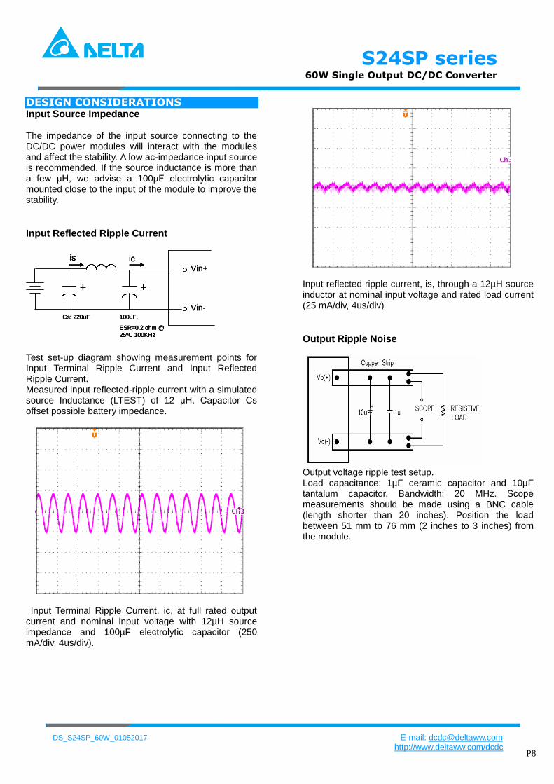
S24SP series 60W Single Output DCDC Converter
DS_S24SP_60W_01052017 E-mail dcdcdeltawwcom
httpwwwdeltawwcomdcdc P9
DESIGN CONSIDERATIONS Layout and EMI considerations Deltarsquos DCDC power modules are designed to operate in a wide variety of systems and applications For design assistance with EMC compliance and related PWB layout issues please contact Deltarsquos technical support team An external input filter module is available for easier EMC compliance design Below is the reference design for an input filter to pass EN55022 (VDE0878) class A (both q peak and average)
EMI filter circuit
Cin=100uF50VNippon chemi-conESR 85 mohm
L1=47uHPCMC063T-4R7MN
C1=68uF50V1812MLCC
CY1=68nF2KV1210MLCC
Test Result
1 MHz 10 MHz1501 kHz 30 MHz
100
200
300
400
500
600
700
00
800
dBμV
Limits
55022MAV
55022MQP
Transducer
8130
Traces
PK+
AV
At T = +25C Typical input voltage and full load
Recommended PCB Layout
It is suggested to use multiple layers PCB and large
size copper on system board which connects to pins of
module that can achieve better thermal performance
FEATURES DESCRIPTIONS Over-Current Protection
The modules include an internal output over-current protection circuit which will endure current limiting for an unlimited duration during output overload If the output current exceeds the OCP set point the modules will shut down (hiccup mode) The modules will try to restart after shutdown If the overload condition still exists the module will shut down again This restart trial will continue until the overload condition is corrected
Over-Voltage Protection
The modules include an internal output over-voltage protection circuit which monitors the voltage on the output terminals If this voltage exceeds the over-voltage set point the modules will shut down and then restart after a hiccup-time (hiccup mode) If latch mode is needed please contact with Delta
Over-Temperature Protection
The over-temperature protection consists of circuitry that provides protection from thermal damage If the temperature exceeds the over-temperature threshold the module will shut downThe module will restart after the temperature is within specification
Remote OnOff
The remote onoff feature on the module can be either negative or positive logic depend on the part number options on the last page For Negative logic version turns the module on
during a external logic low and off during a logic high If the remote onoff feature is not used please short the onoff pin to Vi (-)
For Postive logic version turns the modules on during a external logic high and off during a logic low If the remote onoff feature is not used please leave the onoff pin to floating
Remote onoff can be controlled by an external switch between the onoff terminal and the Vi (-) terminal The switch can be an open collector or open drain
S24SP series 60W Single Output DCDC Converter
DS_S24SP_60W_01052017 E-mail dcdcdeltawwcom
httpwwwdeltawwcomdcdc P10
For 15V signle output (Kohm)
For 24V single output (Kohm)
For example When need trim up to 52V then the external resistor should be 952Kohm between trim pin and Vout- pin When need trim down to 49V then the external resistor should be 2912Kohm between trim pin and Vout+ pin
THERMAL CONSIDERATIONS
Thermal de-rating curve is a standard for customer to make thermal evaluation and make sure the modulersquos components are operated under allowed temperature The modulersquos cooling condition is natural convection In thermal de-rating curve if we know the modulersquos input voltage and output power we can find the allowed maximum ambient temperature
The modulersquos case temperature is a reference to make thermal evaluation If the case temperature exceed the allowed maximum value the moldule may probably have thermal issue
Remote onoff implementation Output Voltage Adjustment (TRIM) Only single output modules have output adjust function To increase the output voltage set point connect an external resistor between the TRIM pin and the Vout(-) To decrease the output voltage set point connect an external resistor between the TRIM pin and the Vout(+) The maximum adjust range is plusmn10 the TRIM pin should be left open if this feature is not used For 5V single output (Kohm)
For 12V single output (Kohm)
S24SP series 60W Single Output DCDC Converter
DS_S24SP_60W_01052017 E-mail dcdcdeltawwcom
httpwwwdeltawwcomdcdc P11
Mechanical Drawing(without heat sink) Mechanical Dimensions Pin Connections
Pin Function
1 Vin+
2 Vin-
3 Onoff
4 Trim
5 Vout-
6 Vout+
Physical outline
Case Size 508254102(20rdquo10rdquo04rdquo)
Case material Al alloy anodize black
Baseplate material Non-conductive FR-4
Pin material Brass finish Matte Tin
plating and Nickel under plating Pin length refer part numbering system
Weight 34grams
All dimensions in mm (inches)
Tolerance XXplusmn05 (XXXplusmn002)
XXXplusmn025 ( XXXXplusmn0010)
Pins Diameter plusmn010(plusmn0004)
Mechanical Drawing(with heat sink) Mechanical Dimensions Physical Outline
1 Heat sink
Material Al-6063
Finish anodize black
Weight 103grams
2 Model weight 46grams
All dimensions in mm (inches)
Tolerance XXplusmn05 (XXXplusmn002)
XXXplusmn025 ( XXXXplusmn0010)
Note
1 add heat sink to help heat dissipation and increase reliability of convert operating at high ambient temperature
2 please refer derating curve while upgrate the operating temperature of converter
S24SP series 60W Single Output DCDC Converter
DS_S24SP_60W_01052017 E-mail dcdcdeltawwcom
httpwwwdeltawwcomdcdc P12
Application notice For modules with through-hole pins they are intended for wave soldering assembly onto system boards
please do not subject such modules through reflow temperature profile
Recommended layout refer below
S24SP series 60W Single Output DCDC Converter
DS_S24SP_60W_01052017 E-mail dcdcdeltawwcom
httpwwwdeltawwcomdcdc P13
Part Numbering System
S 24 S P 050 12 P D F A
Form
factor
Input
voltage
Number
of output
Product
series
Output
voltage
Output
current Onoff logic
Pin
length Option Code
S 24 ndash 9~36V S - Single
P - Series
Number
050 ndash 5V 12 ndash 12A N ndash Negative
P ndash Positive
D - 024rdquo
T - 022rdquo
R - 017rdquo
F - RoHS 66
(Lead Free)
A ndash Standard
(with metal
case)
H ndash With heat
sink
CONTACT wwwdeltawwcomdcdc Email dcdcdeltawwcom
USA
Telephone East Coast 978-656-3993 West Coast 510-668-5100 Fax (978) 656 3964
Europe
Phone +31-20-655-0967 Fax +31-20-655-0999
Asia amp the rest of world
Telephone +886 3 4526107 ext 6220~6224 Fax +886 3 4513485
WARRANTY
Delta offers a three (3) years limited warranty Complete warranty information is listed on our web site or is available upon
request from Delta
Information furnished by Delta is believed to be accurate and reliable However no responsibility is assumed by Delta for
its use nor for any infringements of patents or other rights of third parties which may result from its use No license is
granted by implication or otherwise under any patent or patent rights of Delta Delta reserves the right to revise these
specifications at any time without notice
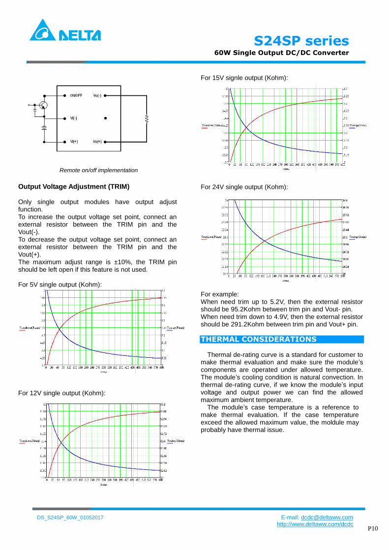
S24SP series 60W Single Output DCDC Converter
DS_S24SP_60W_01052017 E-mail dcdcdeltawwcom
httpwwwdeltawwcomdcdc P10
For 15V signle output (Kohm)
For 24V single output (Kohm)
For example When need trim up to 52V then the external resistor should be 952Kohm between trim pin and Vout- pin When need trim down to 49V then the external resistor should be 2912Kohm between trim pin and Vout+ pin
THERMAL CONSIDERATIONS
Thermal de-rating curve is a standard for customer to make thermal evaluation and make sure the modulersquos components are operated under allowed temperature The modulersquos cooling condition is natural convection In thermal de-rating curve if we know the modulersquos input voltage and output power we can find the allowed maximum ambient temperature
The modulersquos case temperature is a reference to make thermal evaluation If the case temperature exceed the allowed maximum value the moldule may probably have thermal issue
Remote onoff implementation Output Voltage Adjustment (TRIM) Only single output modules have output adjust function To increase the output voltage set point connect an external resistor between the TRIM pin and the Vout(-) To decrease the output voltage set point connect an external resistor between the TRIM pin and the Vout(+) The maximum adjust range is plusmn10 the TRIM pin should be left open if this feature is not used For 5V single output (Kohm)
For 12V single output (Kohm)
S24SP series 60W Single Output DCDC Converter
DS_S24SP_60W_01052017 E-mail dcdcdeltawwcom
httpwwwdeltawwcomdcdc P11
Mechanical Drawing(without heat sink) Mechanical Dimensions Pin Connections
Pin Function
1 Vin+
2 Vin-
3 Onoff
4 Trim
5 Vout-
6 Vout+
Physical outline
Case Size 508254102(20rdquo10rdquo04rdquo)
Case material Al alloy anodize black
Baseplate material Non-conductive FR-4
Pin material Brass finish Matte Tin
plating and Nickel under plating Pin length refer part numbering system
Weight 34grams
All dimensions in mm (inches)
Tolerance XXplusmn05 (XXXplusmn002)
XXXplusmn025 ( XXXXplusmn0010)
Pins Diameter plusmn010(plusmn0004)
Mechanical Drawing(with heat sink) Mechanical Dimensions Physical Outline
1 Heat sink
Material Al-6063
Finish anodize black
Weight 103grams
2 Model weight 46grams
All dimensions in mm (inches)
Tolerance XXplusmn05 (XXXplusmn002)
XXXplusmn025 ( XXXXplusmn0010)
Note
1 add heat sink to help heat dissipation and increase reliability of convert operating at high ambient temperature
2 please refer derating curve while upgrate the operating temperature of converter
S24SP series 60W Single Output DCDC Converter
DS_S24SP_60W_01052017 E-mail dcdcdeltawwcom
httpwwwdeltawwcomdcdc P12
Application notice For modules with through-hole pins they are intended for wave soldering assembly onto system boards
please do not subject such modules through reflow temperature profile
Recommended layout refer below
S24SP series 60W Single Output DCDC Converter
DS_S24SP_60W_01052017 E-mail dcdcdeltawwcom
httpwwwdeltawwcomdcdc P13
Part Numbering System
S 24 S P 050 12 P D F A
Form
factor
Input
voltage
Number
of output
Product
series
Output
voltage
Output
current Onoff logic
Pin
length Option Code
S 24 ndash 9~36V S - Single
P - Series
Number
050 ndash 5V 12 ndash 12A N ndash Negative
P ndash Positive
D - 024rdquo
T - 022rdquo
R - 017rdquo
F - RoHS 66
(Lead Free)
A ndash Standard
(with metal
case)
H ndash With heat
sink
CONTACT wwwdeltawwcomdcdc Email dcdcdeltawwcom
USA
Telephone East Coast 978-656-3993 West Coast 510-668-5100 Fax (978) 656 3964
Europe
Phone +31-20-655-0967 Fax +31-20-655-0999
Asia amp the rest of world
Telephone +886 3 4526107 ext 6220~6224 Fax +886 3 4513485
WARRANTY
Delta offers a three (3) years limited warranty Complete warranty information is listed on our web site or is available upon
request from Delta
Information furnished by Delta is believed to be accurate and reliable However no responsibility is assumed by Delta for
its use nor for any infringements of patents or other rights of third parties which may result from its use No license is
granted by implication or otherwise under any patent or patent rights of Delta Delta reserves the right to revise these
specifications at any time without notice
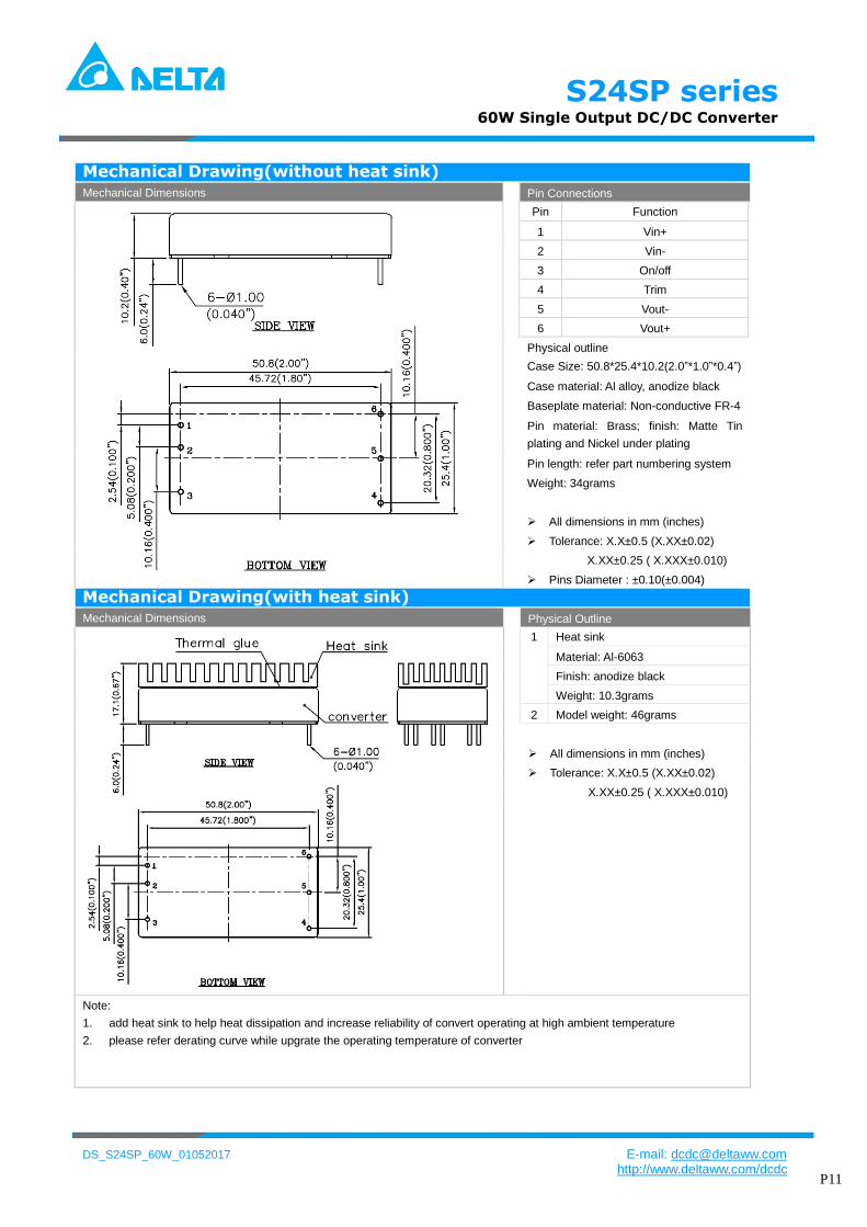
S24SP series 60W Single Output DCDC Converter
DS_S24SP_60W_01052017 E-mail dcdcdeltawwcom
httpwwwdeltawwcomdcdc P11
Mechanical Drawing(without heat sink) Mechanical Dimensions Pin Connections
Pin Function
1 Vin+
2 Vin-
3 Onoff
4 Trim
5 Vout-
6 Vout+
Physical outline
Case Size 508254102(20rdquo10rdquo04rdquo)
Case material Al alloy anodize black
Baseplate material Non-conductive FR-4
Pin material Brass finish Matte Tin
plating and Nickel under plating Pin length refer part numbering system
Weight 34grams
All dimensions in mm (inches)
Tolerance XXplusmn05 (XXXplusmn002)
XXXplusmn025 ( XXXXplusmn0010)
Pins Diameter plusmn010(plusmn0004)
Mechanical Drawing(with heat sink) Mechanical Dimensions Physical Outline
1 Heat sink
Material Al-6063
Finish anodize black
Weight 103grams
2 Model weight 46grams
All dimensions in mm (inches)
Tolerance XXplusmn05 (XXXplusmn002)
XXXplusmn025 ( XXXXplusmn0010)
Note
1 add heat sink to help heat dissipation and increase reliability of convert operating at high ambient temperature
2 please refer derating curve while upgrate the operating temperature of converter
S24SP series 60W Single Output DCDC Converter
DS_S24SP_60W_01052017 E-mail dcdcdeltawwcom
httpwwwdeltawwcomdcdc P12
Application notice For modules with through-hole pins they are intended for wave soldering assembly onto system boards
please do not subject such modules through reflow temperature profile
Recommended layout refer below
S24SP series 60W Single Output DCDC Converter
DS_S24SP_60W_01052017 E-mail dcdcdeltawwcom
httpwwwdeltawwcomdcdc P13
Part Numbering System
S 24 S P 050 12 P D F A
Form
factor
Input
voltage
Number
of output
Product
series
Output
voltage
Output
current Onoff logic
Pin
length Option Code
S 24 ndash 9~36V S - Single
P - Series
Number
050 ndash 5V 12 ndash 12A N ndash Negative
P ndash Positive
D - 024rdquo
T - 022rdquo
R - 017rdquo
F - RoHS 66
(Lead Free)
A ndash Standard
(with metal
case)
H ndash With heat
sink
CONTACT wwwdeltawwcomdcdc Email dcdcdeltawwcom
USA
Telephone East Coast 978-656-3993 West Coast 510-668-5100 Fax (978) 656 3964
Europe
Phone +31-20-655-0967 Fax +31-20-655-0999
Asia amp the rest of world
Telephone +886 3 4526107 ext 6220~6224 Fax +886 3 4513485
WARRANTY
Delta offers a three (3) years limited warranty Complete warranty information is listed on our web site or is available upon
request from Delta
Information furnished by Delta is believed to be accurate and reliable However no responsibility is assumed by Delta for
its use nor for any infringements of patents or other rights of third parties which may result from its use No license is
granted by implication or otherwise under any patent or patent rights of Delta Delta reserves the right to revise these
specifications at any time without notice
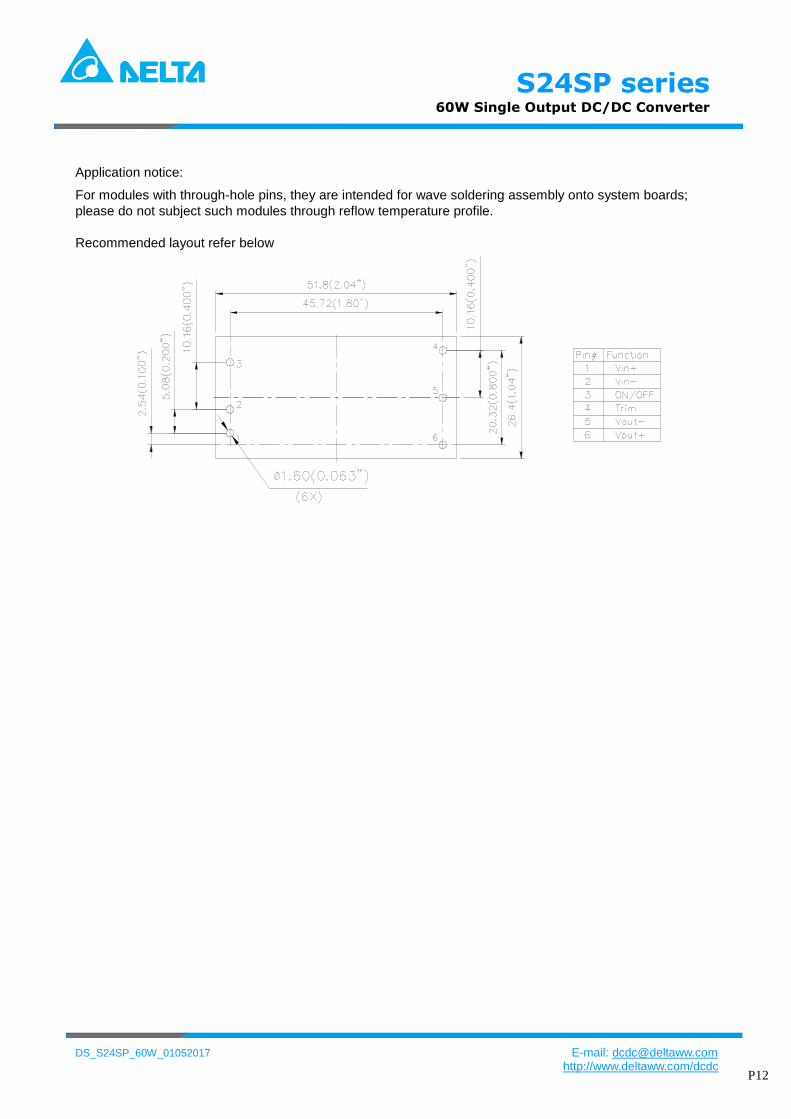
S24SP series 60W Single Output DCDC Converter
DS_S24SP_60W_01052017 E-mail dcdcdeltawwcom
httpwwwdeltawwcomdcdc P12
Application notice For modules with through-hole pins they are intended for wave soldering assembly onto system boards
please do not subject such modules through reflow temperature profile
Recommended layout refer below
S24SP series 60W Single Output DCDC Converter
DS_S24SP_60W_01052017 E-mail dcdcdeltawwcom
httpwwwdeltawwcomdcdc P13
Part Numbering System
S 24 S P 050 12 P D F A
Form
factor
Input
voltage
Number
of output
Product
series
Output
voltage
Output
current Onoff logic
Pin
length Option Code
S 24 ndash 9~36V S - Single
P - Series
Number
050 ndash 5V 12 ndash 12A N ndash Negative
P ndash Positive
D - 024rdquo
T - 022rdquo
R - 017rdquo
F - RoHS 66
(Lead Free)
A ndash Standard
(with metal
case)
H ndash With heat
sink
CONTACT wwwdeltawwcomdcdc Email dcdcdeltawwcom
USA
Telephone East Coast 978-656-3993 West Coast 510-668-5100 Fax (978) 656 3964
Europe
Phone +31-20-655-0967 Fax +31-20-655-0999
Asia amp the rest of world
Telephone +886 3 4526107 ext 6220~6224 Fax +886 3 4513485
WARRANTY
Delta offers a three (3) years limited warranty Complete warranty information is listed on our web site or is available upon
request from Delta
Information furnished by Delta is believed to be accurate and reliable However no responsibility is assumed by Delta for
its use nor for any infringements of patents or other rights of third parties which may result from its use No license is
granted by implication or otherwise under any patent or patent rights of Delta Delta reserves the right to revise these
specifications at any time without notice
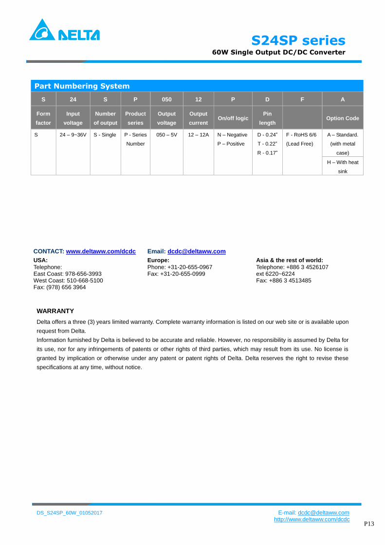
S24SP series 60W Single Output DCDC Converter
DS_S24SP_60W_01052017 E-mail dcdcdeltawwcom
httpwwwdeltawwcomdcdc P13
Part Numbering System
S 24 S P 050 12 P D F A
Form
factor
Input
voltage
Number
of output
Product
series
Output
voltage
Output
current Onoff logic
Pin
length Option Code
S 24 ndash 9~36V S - Single
P - Series
Number
050 ndash 5V 12 ndash 12A N ndash Negative
P ndash Positive
D - 024rdquo
T - 022rdquo
R - 017rdquo
F - RoHS 66
(Lead Free)
A ndash Standard
(with metal
case)
H ndash With heat
sink
CONTACT wwwdeltawwcomdcdc Email dcdcdeltawwcom
USA
Telephone East Coast 978-656-3993 West Coast 510-668-5100 Fax (978) 656 3964
Europe
Phone +31-20-655-0967 Fax +31-20-655-0999
Asia amp the rest of world
Telephone +886 3 4526107 ext 6220~6224 Fax +886 3 4513485
WARRANTY
Delta offers a three (3) years limited warranty Complete warranty information is listed on our web site or is available upon
request from Delta
Information furnished by Delta is believed to be accurate and reliable However no responsibility is assumed by Delta for
its use nor for any infringements of patents or other rights of third parties which may result from its use No license is
granted by implication or otherwise under any patent or patent rights of Delta Delta reserves the right to revise these
specifications at any time without notice