Embed Size (px)
Citation preview
Silverline
S110 Operators Manual Rev: 910
by

Table of Contents
• Machine warranty Page 1
• Safety Instructions Page 2 – 4
• Brief Introduction Page 5
• Machine Configuration Page 6
• Installation and Calibration Page 7– 9
• Machine Operation Page 10-18
• Machine Maintenance Page 19
• Electrical Diagram Page 20
• Pneumatic Diagram Page 21
• Simple Problems/ Oil and Lube Data Page 22

Warranty
This warranty will cover parts, labor and mileage up to 6 months for any mechanical machine part that fails
due to manufacturing.
Excluded from the warranty are all normal wear and consumable items. (bead-breaking bumpers, hoses
and all plastic accessories)
Any machine damage incurred during shipping is not the responsibility of the manufacturer or seller.
(Any damage incurred during shipping is the responsibility of the Freight Company)
Any damaged or injury caused by operator error, misuse, lack of maintenance or faulty utilities
(electrical or air supply) is not the responsibility of the manufacturer or seller.
For all of your service and parts needs please contact Wheel Products by McCourt at 1-800-232-2190
1

Safety Instructions
WARNING - This instruction manual is the most important part of the product. Please read it carefully
and keep it properly.
USE - This machine is only to be used to mount, demount and inflate the tire in the specified scope
and not for any other purpose.
The manufacturer will not be responsible for the damage or injury caused by misuse or improper
operation of the machine.
NOTE - This machine should be operated by trained personnel. When operating, all unauthorized
personnel should be kept far away from the machine.
Please read all safety labels on the machine.
Operators should wear safety protective gear such as working suit, protective glasses, ear
plugs and safety shoes. Keep your hands and body away from the movable parts of the
machine. Necklace, bracelet and loose clothing may cause danger to the operators.
The tire changer should be installed and mounted to a flat and solid floor. Leave at least 20 inches
between the rear and side of the machine to guarantee perfect air flow and enough operating
space.
Do not place the machine in an area of high temperature, high humidity, dust, or with
flammable and corrosive gas.
Do not use any unauthorized machine parts without the permission from the manufacturer. Use
of any unauthorized parts may cause injury to the machine or operator.
Only operate the tire changer with the specified voltage and air pressure.
If you want to move the tire changer, you should ask for guidance from your local service center.
2

Safety Label Instructions
KEEP HANDS FAR FROM
MACHINE WHEN OPERATING
CAREFULLY READ THE
OPERATORS MANUAL
BEFORE OPERATING
WEAR PROTECTIVE GEAR
WHEN OPERATING MACHINE
ELECTRIC SHOCK
DO NOT REACH ANY PART OF YOUR BODY UNDER THE DEMOUNT TOOL.
WHEN BREAKING BEAD, THE BEAD BREAKING BLADE WILL QUICKLY MOVE LEFTWARDS.
WHEN BREAKING THE TIRE BEAD THE BEAD BREAKING BLADE MAY INJUR THE HAND OF THE OPERATOR. REMEMBER: DO NOT TOUCH THE SIDE WALL OF THE TIRE.
WHEN CLAMPING THE RIM, DO NOT REACH YOUR HAND OR OTHER BODY PARTS BETWEEN THE CLAMP AND THE RIM.
DO STAND BEHIND THE COLUMN TO AVOID THE COLUMN FROM INJURING TO THE PERSON WHEN THE SWING ARM IS MOVED.
WHEN BLASTING THE
BOTTOM BEAD OF THE TIRE,
MAKE SURE THE WHEEL IS
CLAMPED.
WHEN OPERATING THE
MACHINE, DO NOT WEAR
LONG HAIR, LOOSE
CLOTHING, OR JEWELRY.
WHEN OPERTING THE
MACHINE, DO NOT REACH
YOUR HAND UNDER THE
MOUNT/DISMOUNT HEAD.
3
Safety Label Instructions
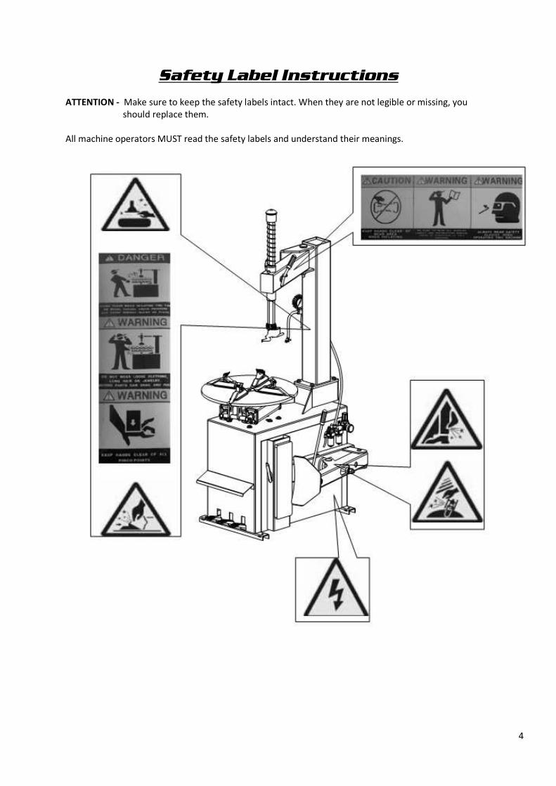
ATTENTION - Make sure to keep the safety labels intact. When they are not legible or missing, you
should replace them.
All machine operators MUST read the safety labels and understand their meanings.
4

Brief Introduction
1.1 BRIEF INTRODUCTION
This series of equipment is the tire changer with fixed column and swing arm. It is suitable to mount, demount and inflate all types of motorcycle and automotive tires with tubes & tubeless. The operation is easy, convenient, safe and reliable. It is the correct equipment for an automotive and tire service shop.
1.2 EQUIPMENT OVERALL DIMENSION (EXCLUDING THE ASSISTANT)
MODEL HEIGHT (mm) LENGTH (mm) WIDTH (mm) NET WEIGHT
LC (GT) 800 73” (1858mm) 38’ (975mm) 35” (895mm) 462/486lbs (210/220KG
1.3 TECHNICAL PARAMETER
Operation Pressure: 120 – 150PSI (8-10bar)
Motor: (standard) 60Hz 110V 1.1Kw
Turntable Speed (6rpm
Noise: <70db (A)
1.4 APPLICATION SCOPE
MODEL MAX. WHEEL DIAMETER MAX. WHEEL WIDTH RIM DIAMTERTER
(OUTER CLAMP)
RIM DIAMETER
(INNER CLAMP)
LC800 960mm (37”) 305mm (12”) 8”-20” 10”-22”
GT800 960mm (37”) 305mm (12”) 10”-20” 12”-23”
(LC800 has adopted the enlargement of the movement base and clamp diameter for the demounting
and mounting the motorcycle tires.)
1.5 ENVIROMENT REQUIREMENT
Ambient Temperature 32°F- 113° (0°C-45°C)
Relative Humidity 30-95%
Sea Level – Max.1000M
Without dust and flammable and explosive gas
The operation space around the machine should not be smaller
the indication in FIG1
If the Machine is installed outdoors, you must have the protective sheds to protect it from
the rain and sun. It is forbidden to use in the site with flammable gas!
FIG 1
5

Configuration and Operation
1. Vertical Shaft Spring 7. Operation Label 13. Column 19. Tire Pressure Arm
2. Rocker Valve 8. Turntable Pedal 14. Inflation Gun 20. Bead Breaking Blade
3. Hexagon Shaft 9. Clamp Pedal 15. Clamp Cylinder 21. Crowbar
4. Demount Head 10. Tire Pressure Pedal 16. Blade Handle 22. Air Tank
5. Jaw 11. Limit Handle 17. Air Source Fitting 23. Inflation Gauge Box
6. Turntable 12. Lock Handle 18. Bead Breaking Cylinder
FIG 2 FIG 3
6
Installation and Calibration
Before installing and servicing, carefully read this manual. The unauthorized change of any spare parts of
the machine may cause damage to the machine.
Installation and Service personnel should have the specific electrical knowledge.
Operators must be trained and authorized.
Before installation, carefully read the equipment list. If you have any questions, please contact your
distributor.
To ensure the success of the installation and servicing, please have the following common tools:
- Two crescent wrenches
- One set of metric socket wrenches
- One set of metric hex wrenches
- One torque wrench
- One set of screw drivers
- One hammer
- One multi-purpose volt meter
3.1 UNPACKING
3.1.1 According to the unpacking instructions, remove the crate and all packaging material to check if the
machine is damaged and to be sure all parts are present.
3.1.2 Keep the package material away from the working area and discard them properly.
3.2 INSTALLATION
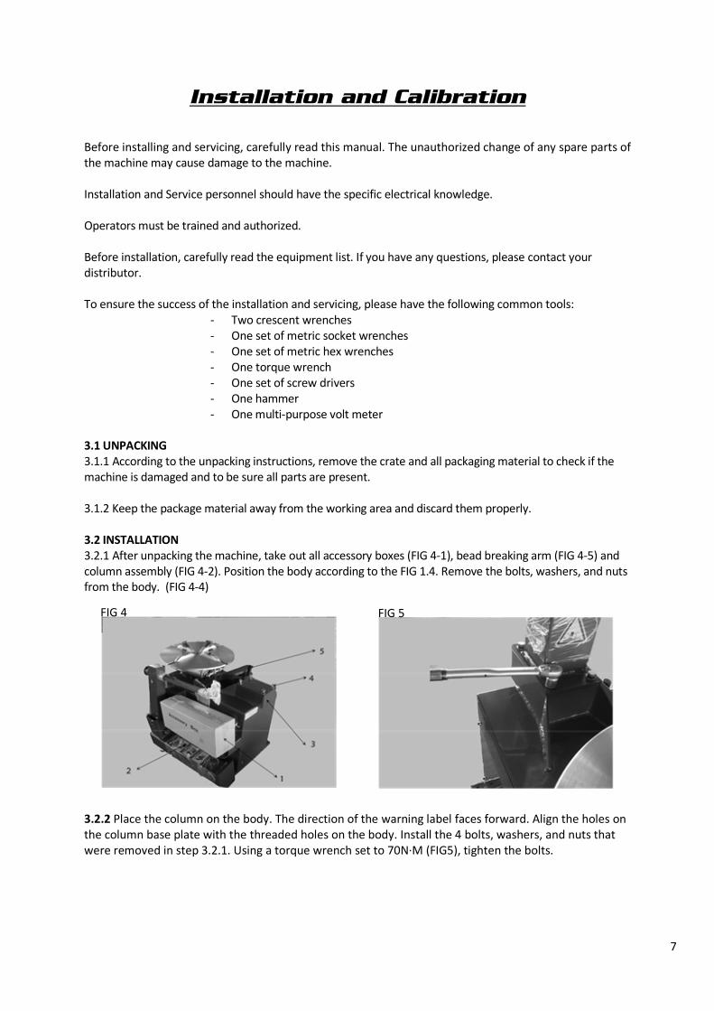
3.2.1 After unpacking the machine, take out all accessory boxes (FIG 4-1), bead breaking arm (FIG 4-5) and
column assembly (FIG 4-2). Position the body according to the FIG 1.4. Remove the bolts, washers, and nuts
from the body. (FIG 4-4)
3.2.2 Place the column on the body. The direction of the warning label faces forward. Align the holes on
the column base plate with the threaded holes on the body. Install the 4 bolts, washers, and nuts that
were removed in step 3.2.1. Using a torque wrench set to 70N·M (FIG5), tighten the bolts.
FIG 4 FIG 5
7
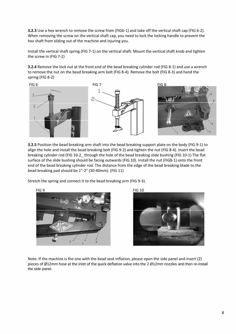
3.2.3 Use a hex wrench to remove the screw from (FIG6-1) and take off the vertical shaft cap (FIG 6-2).
When removing the screw on the vertical shaft cap, you need to lock the locking handle to prevent the
hex shaft from sliding out of the machine and injuring you.
Install the vertical shaft spring (FIG 7-1) on the vertical shaft. Mount the vertical shaft knob and tighten
the screw in (FIG 7-2)
3.2.4 Remove the lock nut at the front end of the bead breaking cylinder rod (FIG 8-1) and use a wrench
to remove the nut on the bead breaking arm bolt (FIG 8-4). Remove the bolt (FIG 8-3) and hand the
spring (FIG 8-2)
3.2.5 Position the bead breaking arm shaft into the bead breaking support plate on the body (FIG 9-1) to
align the hole and install the bead breaking bolt (FIG 9-2) and tighten the nut (FIG 8-4). Insert the bead
breaking cylinder rod (FIG 10-2_ through the hole of the bead breaking slide bushing (FIG 10-1) The flat
surface of the slide bushing should be facing outwards (FIG 10). Install the nut (FIG8-1) onto the front
end of the bead breaking cylinder rod. The distance from the edge of the bead breaking blade to the
bead breaking pad should be 1”-2” (30-40mm). (FIG 11)
Stretch the spring and connect it to the bead breaking arm (FIG 9-3).
Note: If the machine is the one with the bead seat inflation, please open the side panel and insert (2)
pieces of Ø12mm hose at the inlet of the quick deflation valve into the 2 Ø12mm nozzles and then re-install the side panel.
FIG 6 FIG 7 FIG 8
FIG 9 FIG 10
8

3.3 AIR SOURCE FITTING INSTALLATION
When the machine is shipped from the factory, the air supply fitting has been removed and places in the
accessory box (that will need to be re-installed). You may need to install your air fitting that matches up
to your quick connect in your facility.
3.3.1 Install your air supply fitting into the regular assembly of the machine.
3.3.3 Connect the inflation gauge box to the elbow of the fitting on the rear of the tire changer.
3.3.4 The Filter Regulator Assembly has been adjusted at the factory. If it needs changed, lift it up on the
pressure adjustable button (FIG 16-1), twist, and the air pressure will increase. Turn it counterclockwise
to decrease the pressure. Oil Feed: Use a screw driver to turn the screw (FIG 16-2). If clockwise, the oil
drip speed will slow down. If counterclockwise, it will drip faster.
Note: The correct drip flow is 1-2 drops per stroke of the bead breaking shaft.
FIG 11
FIG 16
9
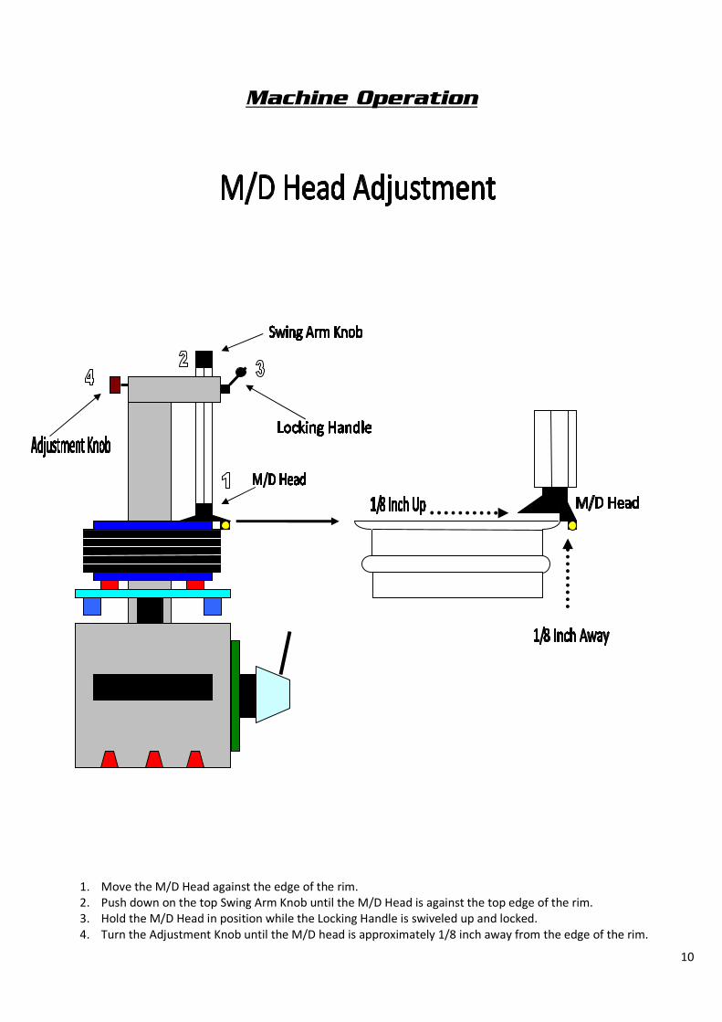
1. Move the M/D Head against the edge of the rim.
2. Push down on the top Swing Arm Knob until the M/D Head is against the top edge of the rim.
3. Hold the M/D Head in position while the Locking Handle is swiveled up and locked.
4. Turn the Adjustment Knob until the M/D head is approximately 1/8 inch away from the edge of the rim.
Machine Operation
10
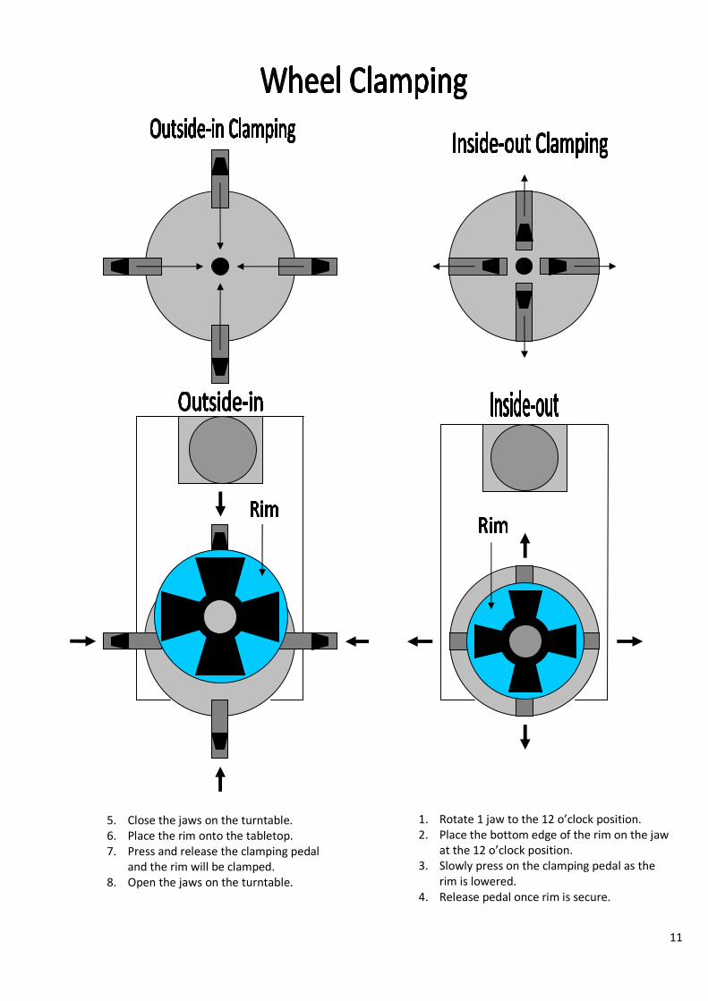
1. Rotate 1 jaw to the 12 o’clock position.
2. Place the bottom edge of the rim on the jaw
at the 12 o’clock position.
3. Slowly press on the clamping pedal as the
rim is lowered.
4. Release pedal once rim is secure.
5. Close the jaws on the turntable.
6. Place the rim onto the tabletop.
7. Press and release the clamping pedal
and the rim will be clamped.
8. Open the jaws on the turntable.
11
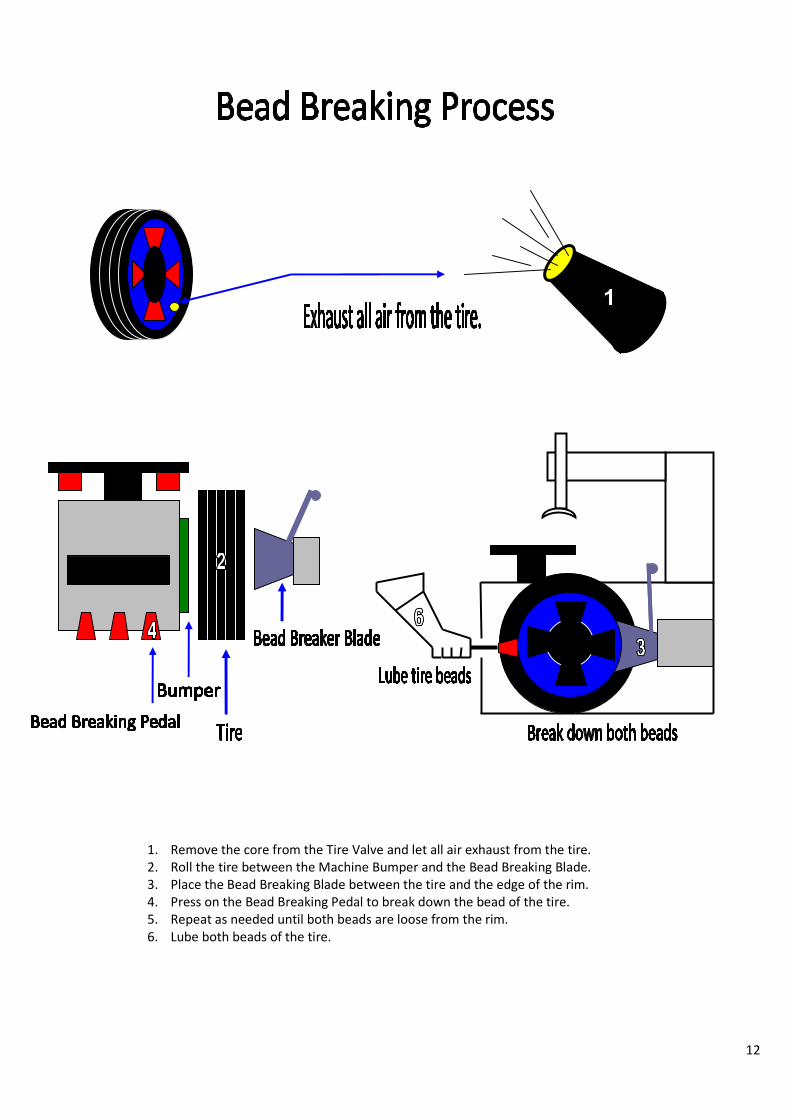
1. Remove the core from the Tire Valve and let all air exhaust from the tire.
2. Roll the tire between the Machine Bumper and the Bead Breaking Blade.
3. Place the Bead Breaking Blade between the tire and the edge of the rim.
4. Press on the Bead Breaking Pedal to break down the bead of the tire.
5. Repeat as needed until both beads are loose from the rim.
6. Lube both beads of the tire.
12

"Demounting the Top Bead"
13

1. Lube both tire beads.
2. Clamp the Wheel and adjust the M/D Head.
3. Place the tire iron between the top bead of the tire and the finger on the M/D Head.
4. Pry down and then rotate the tire until the top bead is loose from the rim.
5. Place the tire iron between the bottom bead of the tire and rim.
6. Lift up on the bottom of the tire, pry down and rotate until the tire is removed from the rim.
“Demounting the Bottom Bead”
14

-15-
15

1. Lube both beads of the tire.
2. Place the bottom bead of the tire on an angle over the M/D Head shoulder and under the knuckle of
the M/D Head finger.
3. Give the tire a slight clockwise twist and then step on the rotation pedal.
4. Continue to rotate until the bottom bead of the tire is mounted.
5. Place the top bead of the tire over the M/D Head shoulder and the knuckle.
6. Give the tire a slight clockwise twist and then step on the rotation pedal.
7. Take care that the top bead of the tire stays down in the drop center of the tire is mounted.
16

17

Note: Tire inflation is a two stage process.
1. Bead seating - Sealing the beads of the tire to the rim.
2. Tire inflation - Inflating the tire to the recommended air pressure.
1. Connect the inflation hose to the valve core of the tire.
2. Pull the tire up until the top bead of the tire is sealed.
3. Step down hard onto the inflation pedal and the blast jets on the tabletop will seat the beads of
the tire.
*Note: The bead blast jets are not needed to seat the beads on all tires.
a. Step lightly on the inflation pedal and air comes out the inflation hose.
b. Step hard on the inflation pedal and air comes out the inflation hose and the blast jets on
the tabletop at the same time.
c. Once tire beads are sealed lift up on the pedal slightly to continue inflating the tire to the
recommended air pressure.
4. Watch the air gauge to see how much air pressure is being put into the tire. *Note: Never inflate any tire on the tire changer over 40PSI.
Note: NEVER inflate over 40 PSI
on the tire machine. Any tire
requiring inflation over 40 PSI
must be placed into a safety
cage.
18
19
Maintenance and Repair
NOTE: Before any maintenance, cut off all power supplies (air and electric). Then, push and hold the
Inflation Pedal to completely deflate the residual air in the machine. To correctly use the tire machine
and prolong its working life, it is necessary to periodically maintain and make adjustments according the
instruction manual. Otherwise, the running life of the machine will be affected and the personnel using
the machine could be injured.
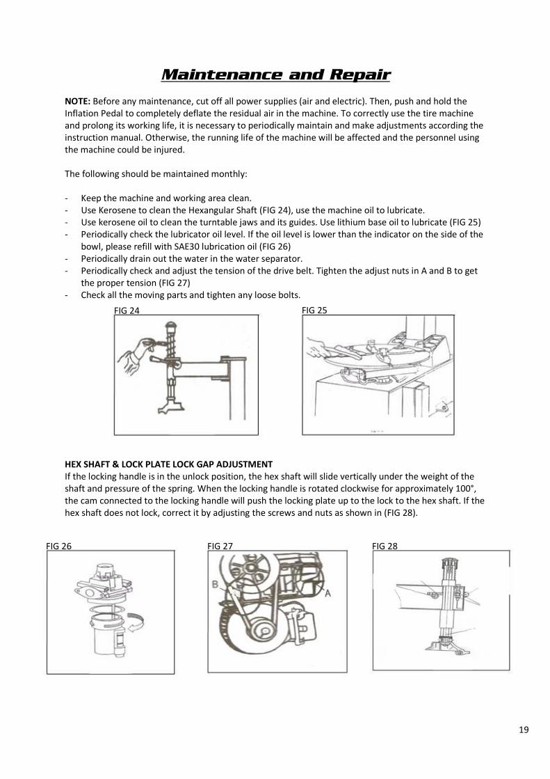
The following should be maintained monthly:
- Keep the machine and working area clean.
- Use Kerosene to clean the Hexangular Shaft (FIG 24), use the machine oil to lubricate.
- Use kerosene oil to clean the turntable jaws and its guides. Use lithium base oil to lubricate (FIG 25)
- Periodically check the lubricator oil level. If the oil level is lower than the indicator on the side of the
bowl, please refill with SAE30 lubrication oil (FIG 26)
- Periodically drain out the water in the water separator.
- Periodically check and adjust the tension of the drive belt. Tighten the adjust nuts in A and B to get
the proper tension (FIG 27)
- Check all the moving parts and tighten any loose bolts.
HEX SHAFT & LOCK PLATE LOCK GAP ADJUSTMENT
If the locking handle is in the unlock position, the hex shaft will slide vertically under the weight of the
shaft and pressure of the spring. When the locking handle is rotated clockwise for approximately 100°,
the cam connected to the locking handle will push the locking plate up to the lock to the hex shaft. If the
hex shaft does not lock, correct it by adjusting the screws and nuts as shown in (FIG 28).
FIG 24 FIG 25
FIG 26 FIG 27 FIG 28

20
110V/220V Electrical Principal Drawing
PE AC
110V
L1 L2 By Customer
FU2 FU1
220V
110V
40A
VOLTAGE SWITCH
2W30A
0
1 2
3
4 2 12 8 6 10
9 5 7 11 1
MOTOR SWITCH
LW5-40
40A/500V
Ye
llow
Gre
en
Re
d
Blu
e
FU₁ FU₂
U₁ U₂ U₃ U₄ Z₁ Z₂
U₁
U₂ U₃
U₄
Z₁
Z₂ PE
M1
TB-2506L
600V/25A
NE BANK
1.1KW 4P
110V 60HZ
TIRE CHANGER DUAL VOLTAGE MOTOR (II)

21

22
TROUBLESHOOTING ANALYSIS AND SOLUTION
LC SERIES MACHINE OIL SAFETY DATA SHEET
MOBIL XHP222
ITEM QUALITY STANDARD
Penetration rate 25° mm/10 280
Dropping point °C 280
Anticorrosion Passed
Basic Oil Viscosity 220
Oxidize stability 100h pressure-drop kpa 35
Water lose percentage 79% 5
Copper corrosion 1A
ISSUE REASON TROUBLESHOOTING
Turntable rotates in one
direction.
Rotation switch contact burned. Change Resolution Switch
Turntable does not rotate. - Belt Damage
- Belt too loose
- Motor or power source has
problems
- Rotation switch contact
damaged
- Change belt
- Adjust the tension of the belt
- Check motor, power source
and power source cable
- Change motor, if motor is
burned change rotation
switch.
Turntable cannot clamp the rim
as normal.
- Jaw Worn
- Clamp cylinder air leakage.
- Change Jaws
- Change the cylinder seats
Quadric and hexangular shaft
cannot lock.
Lock plate not in position Refer to chapter 5
Chassis Pedal does not return. Pedal return spring damage Change Torsion Spring
Motor does not rotate of the
output torque is weak.
- Drive system jammed
- Capacitor failed
- Voltage is too low
- Short-circuit
- Remove the jam
- Change the capacitor
- Wait for power to be restored
- Contact service technician
Cylinder force is too weak. - Air leakage
- Mechanical problem
- Air pressure is low
- Change cylinder seals
- Contact service technician
- Adjust the air pressure to meet
the requirement of 120-150PSI
Air Leakage - Air hose broken
- Pipe fitting broken
- Bad seals
- Oiler low or out of oil
- Change broken parts
- Refill oiler with recommended
SAE30

23
SAE# LUBRICATION OIL
ITEM QUALITY STANDARD
Density 15°C 0.893
Flash Point 224
Pour Point °C -18
Viscosity 40°C 100
Viscosity 100°C 11.2
Viscosity Index 97
2# LITHIUM BASE GREASE
ITEM QUALITY STANDARD
Penetration Rate mm/10 278
Dropping Point °C 187
Copper Corrosion 100°C No Change
Oxidize Stability (99°C 100h) 0.2
Anticorrosion (52°C 48h) 1 Level
Similarity Viscosity (-15°C 10Sˉ¹) / (P a ·S) 800
Water Lose (35°C 1h)% 8
CKC460 INDUSTRIAL GEAR OIL
ITEM QUALITY STANDARD
Viscosity 40°C 461
Viscosity Index 92
Flash Point °C 212
Freezing Point °C -26
Copper Corrosion 100°C 3h 1A
Mechanical Impurity 0.007
Pour Point -10