Embed Size (px)
Citation preview

330kV XLPE Cable Specific Testing Protocol Requirements
K. TANG* D. PATON G. BUCEA TransGrid Australia
S. MASHIO
Y. MURAMATSU J-Power Systems
Japan
SUMMARY Generally, the testing requirements and testing methods of underground power cables with extruded insulation for rated voltages above 150kV are conducted in accordance with the recommendations of IEC 62067. While this Standard does include performance of type tests of XLPE insulation of up to 100oC for 2 hours, it does not make provision for tests at emergency operating temperature of 105ºC or for extended periods, nor does it make provision for the measurement of micro-defects and contaminants in the XLPE and semi-conducting screens. Furthermore, IEC 62067 does not include some specific mechanical and electrical tests which could provide critical data needed to improve confidence in the cable system design over its life. As a result, some utilities may request additional testing in accordance with national standards or their own specifications. In early 2014 TransGrid completed the design, manufacture and installation of a double 330kV XLPE cable circuit and associated condition monitoring system (CMS) across a 15.5km long route in Sydney, Australia. This cable system is the first major 330kV XLPE cable installation in Australia. Given the high reliability requirements within the TransGrid high voltage network, in addition to the IEC 62067 recommended tests, a range of specific tests were introduced to gain a better understanding the performance of the cable system particularly at higher temperature. These additional tests were:
a) Heating Cycle Voltage Test (HCVT) – in this test the cable, cable accessories and CMS were tested as a whole system simulating the actual installation conditions on site.
The HCVT assembly was subjected to 4 separate heating and cooling cycle stages between the ambient and emergency temperatures to simulate operational conditions while a voltage of 2U0 (420kV) was continuously applied as shown in Table 2.1.
21, rue d’Artois, F-75008 PARIS B1_102_2014 CIGRE 2014 http : //www.cigre.org

2
The cable temperature and partial discharges (PD) were measured after each stage of the test. At the completion of the test, the trial assembly was subjected to a step-up voltage breakdown test to determine the system performance limitations after the electrical and thermal stresses applied during the accelerated aging process.
b) Pre-moulded Joint Pressure Test – the intent of this test was to measure and verify the maximum and minimum compression force at the interface of the cable insulation and the EPR rubber mould under minimum and maximum (105oC) operating temperature conditions over the duration of the heating cycles.
c) Friction Coefficient Test – the purpose of this test was to measure the level of friction generated between the cable-core and the corrugated metallic sheath at predetermined operating temperatures.
d) Short Circuit Bonding Test –this test was to verify the thermal stability of the bonding connections between the cable metallic sheath and joint metallic sleeve.
The outcomes of these tests were very beneficial in verifying the cable system design over the full range of operating conditions expected over its operational life; in providing valuable reference data for on-going condition assessments and cable system management and also in simplifying installation work on site in terms of cable snaking and application of pre-moulded joints and bonding connections. KEYWORDS EHV Cable Testing, Heating Cycle Voltage Test (HCVT), Friction Coefficient, Short Circuit Bonding Connection, Joint Interface Pressure.

3
1. Introduction In 2012, when additional 330kV cable circuits were being planned for Sydney – Australia, TransGrid made the decision to install XLPE cables between its Holroyd and Rookwood Road substations. The cable project consisted of a double 330kV cable circuit installed within concrete encased conduits along a 15.5 km route. Given TransGrid’s high network reliability requirements and the importance of these circuits to Sydney’s future power supply needs, it was considered that the testing procedure for these cables had to go beyond the requirements of IEC 62067. The additional tests undertaken by TransGrid, in conjunction with cable manufacturer J-Power Systems included the following:
a) Heating Cycle Voltage Test (HCVT) b) Pre-moulded Joint Pressure Test c) Friction Coefficient Test d) Short Circuit Bonding Test
These tests were designed to verify that the installed cable system would be suitable to perform under all specified operating conditions including cyclic and 72 hour continuous emergency operation.
2. Heating Cycle Voltage Test (HCVT) This test was designed to assess the performance of the 330kV XLPE cable system when subjected to the expected normal and emergency operating conditions. In essence, the HCVT is an accelerated aging test. It also tests and validates the calibration of the CMS with actual measured cable core and joint temperatures. The main loop of the HCVT assembly was approximately 100m in length and incorporated all of the main system components including the 330kV cable, joints (pre-moulded), SF6 terminations, Distributed Temperature Sensing (DTS) and Condition Monitoring System (CMS). The loop was terminated in two outdoor laboratory terminations suitable for 420kV voltage application from a high voltage power transformer. The dummy or “reference” loop, consisting of a short cable section and a pre-moulded joint, was fitted with an array of thermocouples to allow direct measurement of the conductor temperature and temperature gradients over the joint component parts (see Figure 2.1). A section of main and dummy cable loops was installed in 10m long concrete encased ducts to replicate the actual site installation. The specified testing conditions required that the temperature of the hottest section of the trial assembly, i.e. the cable conductor in the duct bank, be in range of 105±3ºC, while the three joint conductor connectors (ferrules) were maintained between 100-105ºC. The two loops of the trial assembly were heated by induced currents in the cable conductors via a series of current transformers. Due to the different thermal characteristics of the cable in the duct bank and of the cable joints, external electric heaters were required to maintain the specified temperatures. Furthermore, during the 72 hour test cycle, it was necessary to consider and manage the impact of the heating resulting from dielectric losses in the main loop as a result of the applied voltage.
4
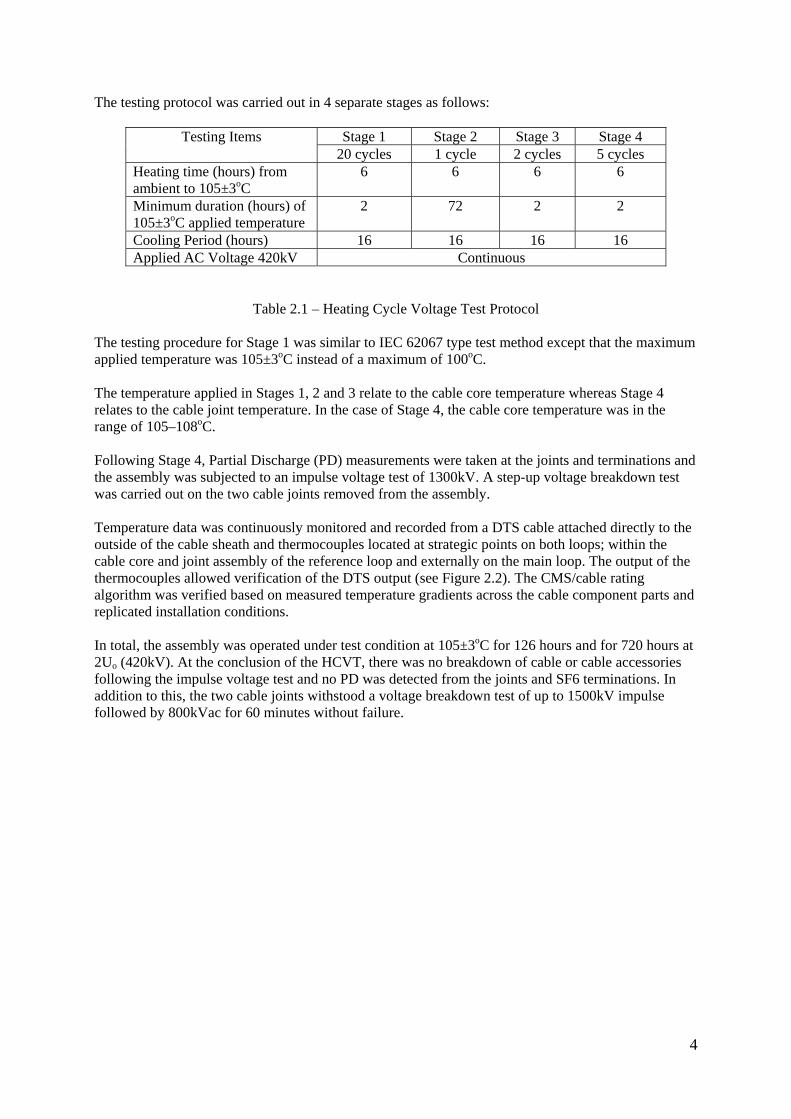
The testing protocol was carried out in 4 separate stages as follows:
Testing Items Stage 1 Stage 2 Stage 3 Stage 4 20 cycles 1 cycle 2 cycles 5 cycles
Heating time (hours) from ambient to 105±3oC
6 6 6 6
Minimum duration (hours) of 105±3oC applied temperature
2 72 2 2
Cooling Period (hours) 16 16 16 16 Applied AC Voltage 420kV Continuous
Table 2.1 – Heating Cycle Voltage Test Protocol The testing procedure for Stage 1 was similar to IEC 62067 type test method except that the maximum applied temperature was 105±3oC instead of a maximum of 100oC. The temperature applied in Stages 1, 2 and 3 relate to the cable core temperature whereas Stage 4 relates to the cable joint temperature. In the case of Stage 4, the cable core temperature was in the range of 105–108oC. Following Stage 4, Partial Discharge (PD) measurements were taken at the joints and terminations and the assembly was subjected to an impulse voltage test of 1300kV. A step-up voltage breakdown test was carried out on the two cable joints removed from the assembly. Temperature data was continuously monitored and recorded from a DTS cable attached directly to the outside of the cable sheath and thermocouples located at strategic points on both loops; within the cable core and joint assembly of the reference loop and externally on the main loop. The output of the thermocouples allowed verification of the DTS output (see Figure 2.2). The CMS/cable rating algorithm was verified based on measured temperature gradients across the cable component parts and replicated installation conditions. In total, the assembly was operated under test condition at 105±3oC for 126 hours and for 720 hours at 2Uo (420kV). At the conclusion of the HCVT, there was no breakdown of cable or cable accessories following the impulse voltage test and no PD was detected from the joints and SF6 terminations. In addition to this, the two cable joints withstood a voltage breakdown test of up to 1500kV impulse followed by 800kVac for 60 minutes without failure.

5
Figure 2.1 – Aerial layout of HCVT trial assembly and reference loop
Figure 2.2 – DTS temperature record during Stage 1
Outdoor Laboratory Cable Terminations
Reference Loop GIS Terminations
Current Transformers
Cable Joints
Cable in Duct Embankment

6
3. Pre-moulded Joint Pressure Test
This test was designed to measure the pressure variations at the interface of the joint pre-moulded Ethylene Propylene Rubber (EPR) insulation with the cable XLPE insulation over a series of heating and cooling cycles between the ambient and emergency operating temperatures. The trial assembly for this test incorporated a series of pressure and temperature sensors (see Figure 3.1) embedded into specially cut groves within the cable insulation prior to placement of the joint insulation (rubber unit). Heating cycles consistent with the first 3 stages of the HCVT (see Table 1.1) were applied with the pressure and temperature outputs from the sensors across the joint continuously monitored with the maximum temperature in the range of 105±3ºC. A summary of the pressure results is shown in Figure 3.2. This test found that the interface pressure between the joint insulation and cable insulation was maintained within the designed range under all test conditions. The pressure remained stable under sustained high temperature, returning to the initial pressure following the repeated heating and cooling cycles. There were no measurable deformations or visible discolorations of the XLPE insulation along the length of the joint rubber unit (see Figure 3.3).
Figure 3.1 – Diagrammatic representation of trial assembly for joint pressure test and friction coefficient test

7
Figure 3.2 – Average pressure measured during heating and cooling cycles
Figure 3.3 – Final appearance of cable insulation (note the temperature and pressure sensors)
4. Friction Coefficient Test This test was designed to determine the friction co-efficient between the cable core and the cable sheath and from this allow an assessment of the likelihood of differential movements of the cable core and sheath when subjected to cyclic rating or from external factors such as heavy vehicular traffic or inclined ground. For this test, a 10m cable sample was cut, straightened and then fixed rigidly to a support frame using a series of cleats (see Figure 3.1). A hydraulic ram was used to push and pull the cable core approximately 300mm from and into the Al sheath respectively. The pull and push operation was planned to be carried out at temperatures ranging from ambient and up to 90oC. Figure 4.1 shows the applied force and displacement of the cable core during the push phase at ambient temperature. It is noted the regular variations of the applied force during the push operation was due to the additional friction between the Al sheath corrugations and the Cu wires inserted in the bedding tape. A similar pattern was observed for the pull test and at 50oC.

8
The test could only be carried out at up to 50oC due to the significant increase in friction coefficient at higher temperatures. At 50oC, the cable core buckled under the force. The results of this series of tests demonstrated that the friction coefficient was much higher than expected in normal design analysis and increased significantly with temperature. Considering the measured results, it was determined that the extent of cable snaking either side of the joint bays could be significantly reduced as could the number of joints required to incorporate core movement sensors. The direct effect of these design changes allowed for a shorter duration of cable installation works and a reduced risk to cable integrity during installation.
Figure 4.1 – Measurement graph for the push test at ambient temperature
5. Short Circuit Bonding Test
This test was designed to verify the thermal and electro-dynamic stability of the connections between copper casing of the cable joint and the aluminium sheath of the cable under a 50kA fault current for 1.0 second. The initial design incorporated a large number of separate copper braided meshes soldered onto the aluminium sheath. The proposed design was difficult to implement on site during cable installation. A test assembly consisted of two 4m long cable sections jointed by a pre-moulded cable joint and fixed rigidly to a support frame via a series of cleats (see Figure 5.1). The braided meshes were installed as designed and during the testing program the number of connections was progressively reduced with each revised assembly retested. The test results are shown in Table 5.1 and a photo in Figure 5.2. Based on the test results, the optimum design for connection of the copper casing with aluminium cable sheath was chosen, leading to substantial time savings in cable jointing, with no loss in performance.

9
Figure 5.1 – Trial assembly general layout
Design Sample 1 Sample 2 Sample 3
Fault current 50kA 50kA 50kA 50kA 50kA 50kA
Fault duration (second)
0.5 1.0 0.5 1.0 0.5 1.0
Test results Pass Pass Pass Pass Pass Failed
Table 5.1 – Testing configurations and results
Figure 5.2 – Breakdown sample of the connection point of Sample 3
Cable Sheath Failed Braided Connections
Joint Casing

10
6. Conclusion IEC 62067 is an internationally recognised standard for the testing of power cable systems for usual conditions and operation. However, it does not make provision for tests at emergency operating temperatures of 105oC or for extended periods. The tests and testing protocols specified by TransGrid and completed by J -Power Systems and discussed above have provided valuable data and information on the cable design and the potential impact of high temperature operation on the cable system and its reliability over its operational life. Also, the test outcomes provided the basis for a number of design modifications and simplification of installation and associated cost savings. The authors would like to recognise the efforts and commitment of the staff in the J-Power Systems testing facilities at the Osaka and Hitaka laboratories for their invaluable assistance and advice during the test program. End of text BIBLIOGRAPHY [1] IEC 62067 – Power cables with extruded insulation and their accessories for rated voltages
above 150kV (Um = 170kV) up to 500kV (Um = 550kV) – Test methods and requirements. [2] JEC-3408-1997 High voltage tests on cross-linked polyethylene insulated cables and their
accessories for rated voltage from 11kV to 275kV. [3] AEIC CS9-06 Specification for extruded insulation power cables and their accessories rated
above 46kV through 345kVac.