Embed Size (px)
Citation preview
FSCM NO. 82918
THIS DOCUMENT IS:
CONTROLLED BY S/V Nuclear Hardentnq - -
ALL REVISIONS TO- THIS DOCUMENT SHALL BE APPROVEO
BY THE ABOVE ORGANIZATION PRIOR TO RELEASE
PREPARED UNDER ] QONTRACT NO. F34601-85-D-3427
1 IR&D
0 OTHER
PREPARED ON Xerox Memlrywriter FILED UNDER
DOCUMENT NO.D500-11659-1 MODEL 8-52
TITLE Nuclear Weaoons Effects Seminar.-,/
< DTIC.MA& LECTE -S AUG 0 11989
ORIGINAL RELEASE DATE DISSUE NO. TO DATE
ADDITIONAL LIMITATIONS IMPOSED ON THIS DOCUMENTWILL BE FOUND ON A SEPARATE LIMITATIONS SHEET.
PREPARED BY eter(ihen .\ 7WP40
".Patton 0 7WP40
B. De~oss 71.P40
T. Siria 7Wp'an
CHECKED BY O~4iu4' -
-om Hewett 7A470
oHaney- 7WP40
SUPERVISED BYOf40Toji ia,--- 7WP40
APPROVED BY i'--y 4 ie--Dale German 7A470
Dr~?.Br~'~ vE~ ~ SIGNATURE QRGN' DATE -
Ar;srv'ei for public releaselDisinuticn Unlimited
DO 6000 2160 REV 3/84 -
Nuclear Weapons Effects Seminar
Document Number D500-11659-1
April 10, 1987
Accesion ForNTIS CRA&IDTIC TAB 0
Ui;annoi rlced 0JustifiCdlIofl
By 57) -j
Oklahoma City Air Logistics Center Avaldbiity CodesMateriel Management Engineering Avail j:'dforS&rvivabiltiy Section Dist A
Tinker Air Force Base, Oklhaoma 73145 Dist
ACKNOWLEDGMENT:
Boeing Military Airplane CompanyOC-ALC S/V Progrwm Off.ce.-- -
3000 Tower Drive, Suite 500Del City, Oklahoma 73115
D500-11659-1
FOREWORD
"Don't worry. It can't happen."Those words were the title of an article by Jean Harrington that appeared in Scien-
tific American in 1940. The statement is in reference to the fears that an explosionmight occur as the result of a chain reaction of uranium fissions. Only about a yearbefore the article was written, two German physicists, Hahn and Strassmann, had managedto split a uranium atom, releasing 200,000,000 electron volts of energy. Follow-upresearch by Paris scientists Joliot, von Halban, Kowarski, and Perrin provided evidencethat, due to the superheat created in fission, a chain reaction could not happen. Mostof the scientific community agreed their findings were probably true.
But then, on December 2, 1942, scientists assigned to the World War II "ManhaLtanProject" managed to build up a nuclear pile to critical mass, subsequently achievingthe first self sustaining atomic chain reaction. Less than three years later, on July16, 1945, the first nuclear bomb was exploded in the Trinity test at Alamogordo, NewMexico. Next, not even one full month later, on August 6 at 8:16 a.m., Hiroshima, Japanexperienced the destructive power of a nuclear explosion when it was used for the firsttime as a weapon. With these, events, America was launched into the "nuclear age"and the nuclear threat became a reality.
The impact of this nuclear threat and how to survive it is a growing area of concern.Increasing importance is being placed on making our weapon systems hardened to theeffects and monitoring and maintaining that hardness. An example of the Air Force'srecognition of the "Survivability" problem is found in AFR 80-38 which says each AirLogistic Center (ALC) Materiel Management Engineering Division (MME) will designatea survivability Office of Prime Responsibility (OPR) within the division, thus providinga central core of engineering survivability expertise for the System Program Managers(SPM's) and Item Managers (IM's) support after Program Management responsibilityTransfer (PMRT). At Oklahoma City Air Logistic Center (OC-ALC), the section assignedthis responsibility is MMEAS.
The material presented herein is intended to be used in conjunction with and supple-mental to the "Nuclear Weapons Effects" seminar developed for the U.S. Air Forceby the Boeing Military Airplane Company (BMAC). Development of the seminar materialwas performed under OC-ALC/MME contract F3460185-D-3427, Engineering AssignmentMMEAS 85-004.
The purpose of the seminar is to provide the following information to newly assigned
MMEAS survivability engineers:
a. An awareness of the magnitude and complexity of the varied nuclear threats.
b. An overview of general and specific Air Force policies and procedures inthese areas:
1. A.F. Tech Order system2. Maintenance Data Collection system3. Hardness Maintenance/Hardness Surveillance4. Configuration control
iD500-1 1659-1
c. A detailed look at the "electronic" threat, Electromagnetic Pulse (EMP),and how to safeguard against it.
d. Methods of detecting degradations in the hardness of a system or sub-systemthrough testing and inspection.
The seminar includes some theoretical background data, but focuses on practicalapplications.
Material presented during this seminar is provided as guidance and is not to betaken as directive in nature.
Acknowledgment is hereby given to the following people. for their contributionto the preparation of this document: Brent DeMoss, Jim Patton, Torn S.-ia, Bob Haneyand Peter Richeson.
Dii
D500-1 1659-1

TABLE OF CONTENTS
PAGE
FOREWORD i
TABLE OF CONTENTS iii
LIST OF ACRONYMS AND ABBREVIATIONS iv
NOMENCLATURE vii
CHAPTER 1: THE THREAT 1
SECTION 1 Weapon Types 2
Energy Forms 2
SECTION 2 Blast and Shock 5
SECTION 3 Thermal 18
SECTION 4 Radiation 30
Initial Radiation 30
Residual Radiation 44
SECTION 5 EMP 53
SECTION 6 TREE 122
CHAPTER 2: THE DEFENSE (Hardening Against the Threat)
SECTION 7 Hardness Critical Items 141
SECTION 8 Hardness Maintenance/Hardness Surveillance 149
SECTION 9 Testing 160
GLOSSARY 167
REFERENCES 177
PROBLEMS 181
SOLUTIONS 185
iii05D500-1 1659-1

ACRONYMS AND ABBREVIATIONS
A/C Aircraft
AFB Air Force Base
AFLC Air Force Logistics Command
AFR Air Force Regulation
AFSC Air Force Systems Command
AFWL Air Force Weapons Lab
ALC Air Logistics Center
ANSI American National Standards Institute
ASD Aeronautical Systems Division
ASTM American Society for Testing and Materials
BMAC Boeing Military Airplane Company
CI Configuration Item
CI Critical Item 9DDI Direct Drive Injection
DESC Defense Electronics Supply Center
DITMCO Drive-In Theater Movie Company
DNA Defense Nuclear Agency
DOD Department of Defense
DODISS Department of Defense Index of Specifications and Standards
ECP Engineering Change Proposal
EMI Electromagnetic Interference
EMP Electromagnetic Pulse
FET Field Effect Transistor
FSC Federal Supply Class
FSD Full Scale Development
FSED Full Scale Engineering Development
iv
D500-11659-1

HA Hardness Assurance
HADD Hardness Assurance Design Documentaition
HCI Hardness Critical Item
HCP Hardness Critical Process
HDI Hardness Dedicated Item
HM Hardness Maintenance
HOB Height of. Burst
HPD Horizontally Polarized Dipole
HS Hardness Surveillance
IEEE Institute of Electrical and Electronics Engineers
IM Item Manager
LCS Life Cycle Survivability
LPA Log Periodic Antenna
LRU Line Replaceable Unit
MDC Maintenance Data Collection
MM E Material Management Engineering
MMICS Maintenance Management Information and Control System
NSN National Stock Number
OC-ALC Oklahoma City Air Logistics Center
OPR Office of Prime Responsibility
PMD Program Management Directive
PMRT Program Management Responsibility Transfer
PTO Preliminary Technical Order
R & D Research and Development
RFP Request for Proposal
SAC Strategic Air Command
SAP System Analysis Program
SCORCH Source for Component Overstress Response Characteristics
V
D500-1 1659-1

SCR Silicon Controlled Rectifier
SEU Single Event Upset
SGEMP System Generated Electromagnetic Pulse
SMR Source, Maintenance, and Recoverability
SON Statement of Operational Need
SPM System Program Manager
SPO System Program Office
SR U Shop Replaceable Unit
TAC Tactical Air Command
TCTO Time Compliance Technical Order
T.O. Technical Order
TPD Terminal Protection Device
TREE Transient - Radiation Effects on Electronics
USAF United States Air Force
UV Ultraviolet
VAR Vulnerability Analysis Report
VPD Vertically Polarized Dipole
VSWR Voltage Standing Wave Ratio
WUC Work Unit Code
vi
D500-11659-1
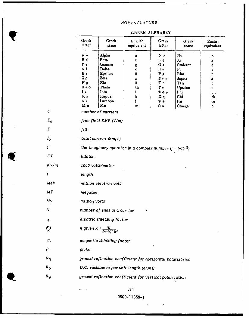
NOMENCLATURE
_GREEK ALPHABET
Greek Greek English Greek Greek Englishletter name equivalent letter name equivalent
Aa Alpha a N s Nu nB Beta b I E Xi xP t Gamma g 0o Omicron 6A 8 Delta d fI r Pi pEE Epsilon 6 Pp Rho rZ Zeta Z X-a, I Sigma aH !7 Eta e Tr Tau t0 0 0 Theta th T u Upsilon u
Iota i 00,0 Phi phKappa k X X Chi ch
A X Lambda I * % Psi psM Mu m Omega 5
c number of carriers
Eo free field EMP (V/m)
F fill
10 total current (amps)
j the imaginary operator in a complex number (j = (-1).5)
KT kiloton
KV/m 1000 volts/meter
I length
MeV million electron volt
MT megaton
Mv million volts
N number of ends in a carrier
e electric shielding factor
(n) n given k = n!(n-k)! k!
m magnetic shielding factor
P picks
Rh ground reflection coefficient for horizontal polarization
R o D.C. resistance per unit length (ohms)
Rground reflection coefficient for vertical polarization
vii
DSO0-11659-1

NOMENCLATURE (contd)
S shield effectiveness (dB)
V/m volts per meter
Vo voltage between cable and ground plane (volts)
Voc open-circuit voltage
W weapon yield
Zc characteristic impedance (ohms)
Zg internal impedance per unit length of a ground plane (ohms)
Zm Impedance of a metal shield
Zt transfer impedance (ohms)
real part of propagation constant
0 imaginary part of propagation constant
Y propagation constant 96 skin depth (meters)
permitivity (farad/meter)
Ipermeability (henry/meter)
a conductivity (mhos)
"' frequency (radians/sec.)
pviii
0500-1 1659-1

CHAPTER 1: THE THREAT
The destructive power of a weapon is due to the rapid release of high levels ofenergy in a small area when the weapon explodes. The magnitude and form of damageresulting from a w.apon detonation are dependent upon the weapon type, the amountof energy being released from the weapon, the distance from the explosion, and theamount of time elapsed between the time of explosion and the time the effects of theexplosion reach the target.
There are two primary types of explosive devices: chemical, such as T.N.T., andnuclear. For either of these, the "output," or the effective yield, is measured in termsof the total amount of energy released in the explosion, relative to the amount by weightof TNT. which would produce the same total energy. The yield for a nuclear deviceis typically given in terms of kilo-tons (thousand tons), or mega-tons (million tons).These are abbreviated as KT and MT respectively. In terms of energy, one KT yieldsapproximately 1012 calories. The energy output from an explosion is detectable inthe forms: blast and shock, the change in pressure due. to an explosion; thermal, thesudden increase in temperature; and nuclear radiation, the result of radioactive elementsin a nuclear explosion.
10500-11659-1
SECTION 1PRINCIPLES OF NUCLEAR EXPLOSIONS
Nuclear explosions are classified as fission reactions or fusion reactions. Fissionrefers to the splitting of the nucleus of a fissionable atom. Fusion is accomplishedby the uniting of two Zight nuclei to form the nucleus of a heavier atom. In either case,the resultant nuclei have less mass than the original with the difference being convertedto energ?. That energy appears in the form of blast, heat, x-rays, gamma rays, neutrons,etc., all of which will be discussed later.
Fission occurs when a free neutron, while traveling through the isotope materialstrikes the nucleus of one of the atoms and causes the nucleus to break in two. Whenthis fission occurs, there is an energy release of approximately 200 MeV or 32 x 10- 6
Joules and there will also be 2 or 3 neutrons thrown free from the split atom. The neu-trons freed by the fission process are then able to move in such a manner as to possiblycollide with another nucleus, thus causing another fission. A fission created by a neutronreleased from a previous fission constitutes a chain reaction. When the number of fissionsoccurring during one generation is equal to or greater than the number of fissions whichtook place in the preceding generation, the chain reaction is said to be self sustaining.Using select isotopes of uranium and plutonium, a fission or fusion explosion can emitabout 2 x 1026 neutrons per megaton yield.
The history of the split uranium atom goes back to just prior to January 26, 1939.It was on this date that the news was released to the Fifth Washington Conference onTheorptical Physics that Dr. Otto Hahn had, only a few wee.cs earlier, shattered a uranium 9atom using neutron bombardment. Dr. Hahn, a noted German physicist working at theKaiser Wilhelm Institute in Berlin, was rummaging through the remains of one of hisexperiments and found that barium was one of the products resulting from neutron bulletsblasting a uranium nucleus in two. Barium is only slightly heavier than half the weightof uranium. Others, having inside information, scrambled to duplicate Hahn's find.Ten days before the conference, Frisch and Meitner, in Copenhagen, verified the resultsand on January 25, one day before the conference, a group of Columbia University physi-cists carried out a similar experiment. By the termination of the conference on January28, Carnegie Institution of Washington, Johns Hopkins, and the University of Californialaboratories had provided three more confirmations.
Whether or not a fission takes place and whether or not a chain reaction of fissionsoccurs and whether or not the number of fissions increase rapidly enough to have anexplosion are all dependent upon the mass of the fissionable material, the containerin which the material is housed, and the presence of other elements having lighter nuclei.For large amounts of nuclear energy to be released, a chain reaction of fissions mustoccur. The fission of one pound of uranium or plutonium produces approximately an8 KT burst.
The mass factor is divided into three classifications: subcritical, critical, andsupercritical. For the purposes of this discussion, the symbol "f" will be used to representthe fission rate factor which will define the criticality of the mass. This factor in equa-tion form is given as:
= number of fissions in generation n 9f number of fissions in generation n-I
2
D500-11659-i
When "f" is less than 1, the mass is considered subcritical, for 'If" greater than1, the mass is supercritical, Lnd a factor "f" of unity represents critical mass. When
the mass is critical, the chain reaction is such that no explosion will occur, but theheat generated by the fissions will cause the substance to melt down or alter in form
toward subcritical. To crease an explosion, supercritical mass is required. Subcritical
mass provides for a non-explosive decay of the radioactive material. The decay takes
place as neutrons are lost by escaping from the substance.
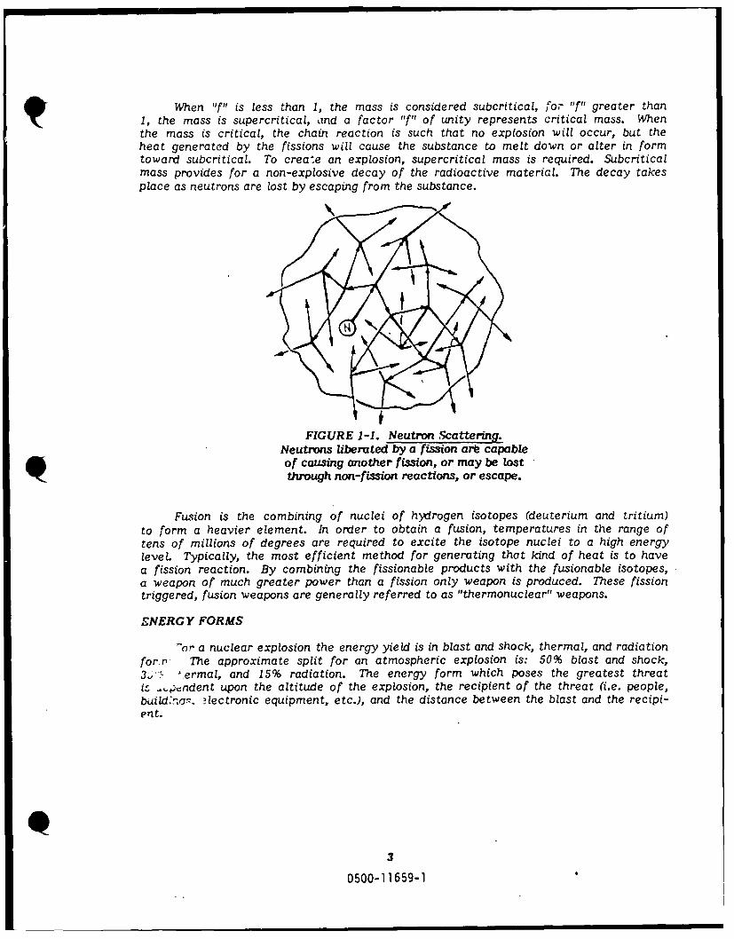
FIGURE 1-1. Neutron Scattering.
Neutrons liberated by a fission ar capableof causing another fission, or may be lostthrough non-fission reactions, or escape.
Fusion is the combining of nuclei of hydrogen isotopes (deuterium and tritium)
to form a heavier element. In order to obtain a fusion, temperatures in the range of
tens of millions of degrees are required to excite the isotope nuclei to a high energy
level. Typically, the most efficient method for generating that kind of heat is to have
a fission reaction. By combining the fissionable products with the fusionable isotopes,a weapon of much greater power than a fission only weapon is produced. These fissiontriggered, fusion weapons are generally referred to as "thermonuclear" weapons.
ENERGY FORMS
-or a nuclear explosion the energy yield is in blast and shock, thermal, and radiation
for r The approximate split for an atmospheric explosion is: 50% blast and shock,
3.-. lermal, and 15% radiation. The energy form which poses the greatest threat
it, _.,pndent upon the altitude of the explosion, the recipient of the threat (i.e. people,build'nar. ?lectronic equipment, etc.), and the distance between the blast and the recipi-ent.
3
D500-11659-1

BURST CLASSIFICATION
Because the nuclear threat factors are a function of the height of burst, explosionsare classified as one of the four: subsurface, surface, air, or high altitude. For example,blast, shock, and thermal threats are more significant from a surface burst than froma high altitude burst. EMP, on the other hand, is a greater concern as a result of ahigh altitude blast.
A subsurface burst is one in which the weapon's center of gravity is beneath theground or under the surface of water. A fully contained subsurface burst is one in whichthe fireball does not reach the surface. A surface burst is one which occurs either onthe earth's surface or slightly above. The allowable distance above the surface whichwill differentiate between a surface burst and an air burst is determined by the sizeof the fireball. When the altitude is such that the burst is within the atmosphere (under100,000 feet), and the fireball, at its greatest intensity no longer touches land or water,the explosion is called an air burst. A fireball can grow to over one mile across at itsmaximum brilliance, requiring a detonation altitude of over 2,500 feet to be an air burst.A high altitude burst is generally defined as one which occurs above 100,000 feet (abovethe altitude where there is any significant atmosphere).
4
D500-11659-1
SECTION 2
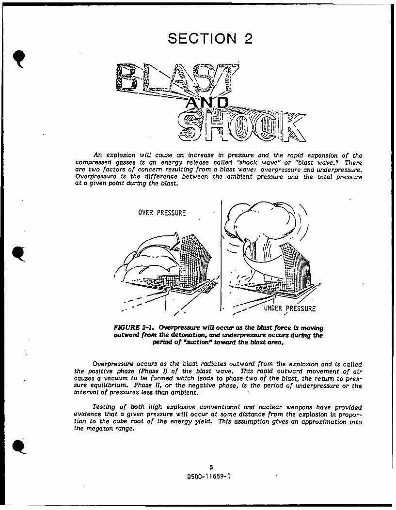
An explosion will cause an increase in pressure and the rapid expansion of thecompressed gasses is an energy release called "shock wave" or "blast wave." Thereare two factors of concern resulting from a blast wave: overpressure and underpressure.Overiressure is the difference between the ambient pressure and the total pressureat a given point during the blast.
OVER PRESSURE -
PRESSURE
FIGURE 2-1. Overpressure will occur as the blast force is movingoutward from the detonation, and underpre3sure occurs during the
period of "suctonn toward the blast area.
Overpressure occurs as the blast radiates outward from the explosion and is calledthe positive phase (Phase ) of the blast wave. This rapid outward movement of aircauses a vacuum to be formed which leads to phase two of the blast, the return to pres-sure equilibrium. Phase II, or the negative phase, is the period of underpressure or theinterval of pressures less than ambient.
Testing of both high explosive conventional and nuclear weapons have providedevidence that a given pressure will occur at some distance from the explosion in propor-tion to the cube root of the energy yield. This assumption gives an approximation intothe megaton range.
50500-11659-1

(r/rl) = (W/W 1)1/3 (Eqtn 2-1)
Where r I and W1 are the reference slant range and energy yield, respectively,W is the energy yield of the weapon in question, and r is the slant range at the pressureof interest.
EXAMPLE 2-1:
GIVEN: A 1KT weapon produces a 200 psi overpressure 275 feet fromthe blast.
FIND: At what distance would a IOKT blast provide the same level
of overpressure?
SOLUTION: r I = 275ft, W1 = 1KT, W = 1OKT
r = r (WIW1)11 3
r = 592 feet.
The same relationship exists between the time of arrival of the positive phase ofthe blast and the energy yields, as shown in Equation 2-2.
(t/t 1 ) = (W/W 1)1 / 3 (Eqtn 2-2)
Where t I is the reference time and t is the time in question.
The preceding relationships are very simplistic and do not take into account suchfactors as height of burst, reflection of the blast front off of a surface, etc.
Typical physical characteristics of a blast wave are shown in Figure 2-2. As shown,the shock front moves away from the burst center and the incident wave is reflected bythe earth. When the reflected wave intercepts the incident wave, a combining of pressuresis created. The point where this combination occurs is known as the "triple point" andthe area below the triple point is called the "Mach Stem Region".
0 1
0500-11 ]659-1

TRIPLE PODINT ,PATH OF
REGULAR REFLECTIONI
FIGURE 2-2. The Mach Sterm Reqion, (shaded area),is the region inl which the incident blast wave and the
reflected wave result in additive pressure&.
Ideally, the pressure generated at the shock front would be the simple addition ofthe incident and reflected wave pressures, but this is not the case. The pressure belowthe triple point is dependent on the incident overpressure, P, and the angle of incidence,
The following graph (2-1) shows the relationship between the incident and reflectedpressures for angles of incidence between zero and 90 0. Pr is the reflected blastoverpressures and P is the initial peak incident overpressure.
CT4
2 INIDENT OVERPRESSURE -5 PSI_ _0j 2I __
o-----------------------W
LA.
0 10 20 30 40 50 ISO 70 so 90
ANGLE OF INCIDENCE.aGRAPH 2-1. Reflected Overprmaures Ratio.
T0500-1 1659-1
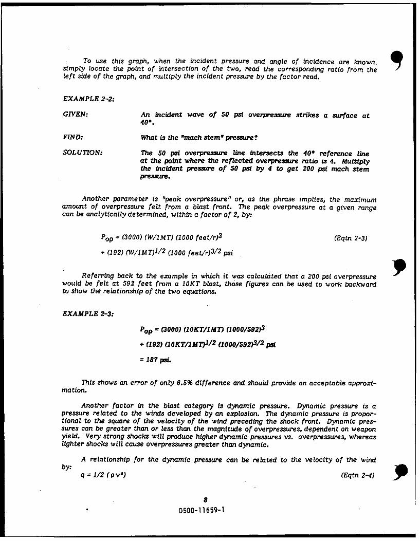
To use this graph, when the incident pressure and angle of incidence are known, qsimply locate the point of intersection of the two, read the corresponding ratio from theleft side of the graph, and multiply the incident pressure by the factor read.
EXAMPLE 2-2:
GIVEN: An incident wave of 50 psi overpresiure strikes a surface at
400.
FIND: What is the "mach stem" pressure?
SOLUTION: The 50 psi overpressure line intersects the 400 reference lineat the point where the reflected overpressure ratio is 4. Multiplythe incident pressure of 50 psi by 4 to get 200 psi mach stempre ue.
Another parameter is "peak overpressure" or, as the phrase implies, the maximumamount of overpressure felt from a blast front. The peak overpressure at a given rangecan be analytically determined, within a factor of 2, by:
Pop = (3000) (W/1MT) (1000 feet/r)3 (Eqtn 2-3)
+ (192) (W/IMT)1 / 2 (1000 feet/r)3 / 2 psi
Referring back to the example in which it was calculated that a 200 psi overpressurewould be felt at 592 feet from a IOKT blast, those figures can be used to work backwardto show the relationship of the two equations.
EXAMPLE 2-3:
Pop = (3000) (1OKT/1MT) (1000/592)3
+ (192) (1OKT/1MT)1 1 2 (1000/592)3/2 psi
= 187 psi.
This shows an error of only 6.5% difference and should provide an acceptable approxi-mation.
Another factor in the blast category is dynamic pressure. Dynamic pressure is apressure related to the winds developed by an explosion. The dynamic pressure is propor-tional to the square of the velocity of the wind preceding the shock front. Dynamic pres-sures can be greater than or less than the magnitude of overpressures, dependent on weaponyield. Very strong shocks will produce higher dynamic pressures vs. overpressures, whereaslighter shocks will cause overpressures greater than dynamic.
A relationship for the dynamic pressure can be related to the velocity of the windby:
q = 1/2 (Pv 5 ) (Eqtn 2-4)
8
D500-11659-1

Where p is the density of air behind the shock front, and v is the velocity of the
air moving behind the shock front.
RELATIONSHIPS OF BLAST FACTORS
As engineers at an Air Logistics Center (ALC), your involvement with the effectsof shock will likely be minimal, if not nonexistent. The information provided is therefore,only introductory. Since imitation is the sincerest form of flattery, Messrs. Glasstoneand Dolan should feel gratified that nearly all material herein on shock (and thermalradiation) is a condensed version of their "The Effects of Nuclear Weapons."
103 V. 1 / -00
7 70
-4 40
2 , 20J
7 -
o~ V .i~Ll
z 10'04! z
o )-
re
0 L
I0001.0659-
D 0
a. AP Y-.BatWv hmtraisqWD500-11-5.7
I .I

The "Blast Wave Characteristics" graph (2-2) allows a comparison look at the variousfactors making up the blast and shock threat. Some examples of the things that are shownin this graph include:
1) Peak overpressure and reflected pressure start at about the same magnitudewhen pressures are low, but at maximum values shown, reflected pressure isfive times greater than peak overpressure.
2) Dynamic pressure is less than peak overpressure in ranges below 70 psi,-and -largerthan peak overpressure for ranges above 70 psi.
The following pages contain various graphs showing blast factor relationships. Witheach graph, there is a description, as well as a problem solving example.
Graph 2-3 shows peak overpressure as a function of Height of Burst (HOB) and distancefrom ground zero. These values are scaled to a I KT burst using the cube root rule:
S = W 3 (Eqtn 2-4)
dl tl hl
An example illustrating the use of this graph is shown below:
EXAMPLE 2-4:
GIVEN: An 80 KT detonation at a height of 860 feet.
FIND: The distance from ground zero to which 1,000 psi overpressureextend&
SOLUTION: The corresponding height of burst for I KT, i.e., the scaled height,is:
hl - h 860 = 200 feet.w1' 3 (80)1/3
From graph 2-3, an overpressure of 1,000 psi extends 110 feet from ground zerofor a 200-foot burst height for a 1 KT weapon., The corresponding distance for 80 KTburst is:
d =dlW1 / 3 = 110 X (80)1/3 = 475 feet.
10
0500-11659-1
200 REFLECTION
20
0 100 200. 300 400
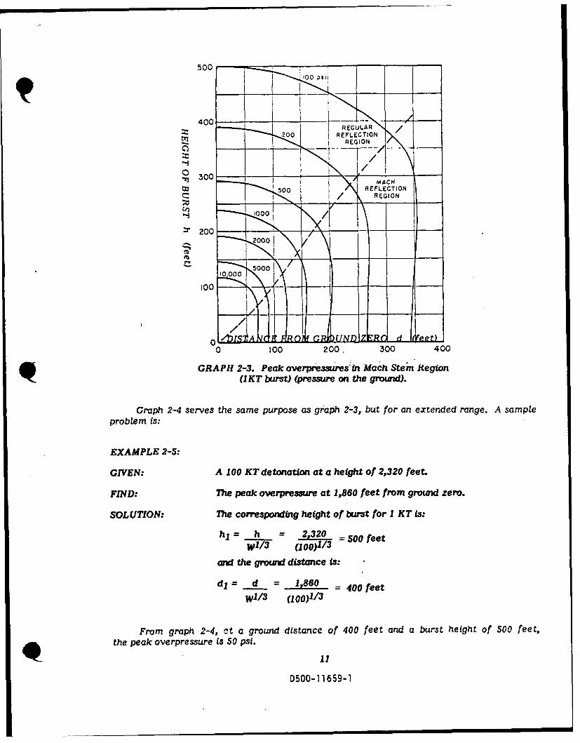
GRAPH 2-3. Peak overpressures nr Mach Stem Region(I KT burst) (pressure on the ground).
Graph 2-4 ser'ves the same purpose as graph 2-3, but for an extended range. A sampleproblem is:
EXAMPLE 2-5:
GIVEN: A 100 KT detonation at a height of 2,320 feet.
FIND: 7Te peak overpressure at 1,860 feet from ground zero.
SOLUTION:- The corresponding height of burst for 1 KT is:
hl h t 2,320 = 500 feetW1' 3 (100)1/3
and the ground distance is:
dl d = 1,860 =400 feetW11 3 (100)1/3
From graph 2-4, at a ground distance of 400 feet and a burst height of 500 feet,the peak overpressure is 50 psi.
D500-1 1659-1
,000 -
REGULAR
400 _ _ _
EGO
~~~20 20 _ _ _ '
0 200 400 600 800 1,000 1,200 1,400DISTANCE FROM GROUND ZERO d (feet)
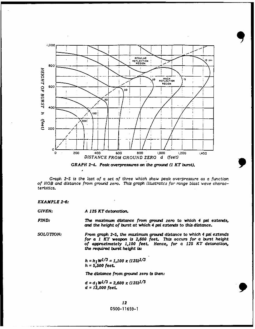
GRAPH 2-4. Peak overpressures on the ground (1 KT burst)..1
Graph 2-S is the last of a set of three which show peak overpressure as a functionof HOB and distance from ground zero. This graph illustratcs far range blast wave charac-teristics.
EXAMPLE 2-6:
GIVEN: A 125 KT detonation.
FIND: The maximum distance fromt ground zero to which 4 psi extends,and the height of burst at which 4 psi extends to this distance.
SOLUT7ON: From graph 2-5, the maximum ground distance to which 4 psi extendsfor a 1 KT weapon is 2,600 feet. This occurs for a burst heightof approximately 1,100 feet. Hence, for a 125 KT detonation,the required burst height is:
ht = ht1 W1 3 = 1,100 x (1 25)1/3h=5,500 feet.
T'he distance from ground zero is then:
d = dl w113 = 2,600 x (125)1/3
d = 13,000 feet.
12D500-1 1659-1
5,000-
I I I I
4,000
03,000
2,000
00o0 2,000 3,000 4,000 5,000 6,000 7,000
DISTANCE FROM GROUND ZERO d (feet)
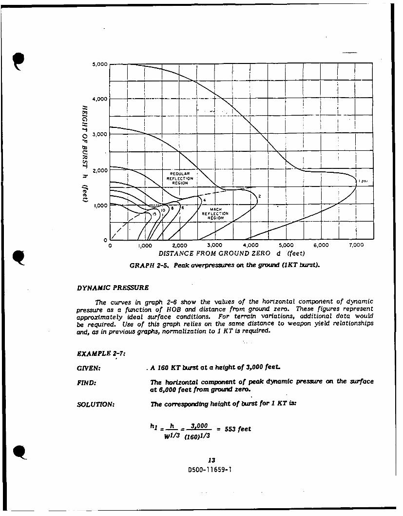
GRAPH 2-5. Peak overpressures on the ground (1KT burst).
DYNAMIC PRESSURE
The curves in graph 2-6 show the values of the horizontal component of dynamicpressure as a function of HOB and distance from ground zero. These figures representapproximately ideal surface conditions. For terrain variations, additional data wouldbe required. Use of this graph relies on the same distance to weapon yield relationshipsand, as in previous graphs, normalization to 1 KT is required.
EXAMPLE 2-7:
GIVEN: A 160 KT burst at a height of 3,000 feet.
FIND: The horizontal component of peak dynamic pressure on the surfaceat 6,000 feet from ground zero.
SOLUTION: The corresponding heiqht of burst for I KT is:
h= h.h= 3,000 = 553 feet
wi, 3 (160)1/3
13D500-11659-1
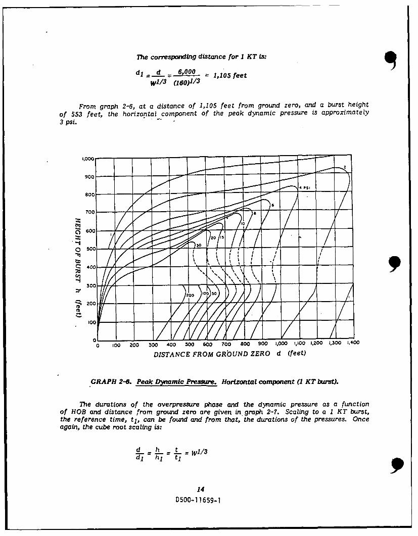
The corresponding distance for I KT is:
dl=d 6,000 =1,105 feet
wi'3 (160)1/3
From graph 2-6, at a distance of 1,105 feet from ground zero, arnd a burst heightof 553 feet, the horizontal component of the peak dynamic pressure is approximately3 psi. -
1,00
0-0 -1 90
40 10 20 3040 5060 70 8090 ,0 ,0 ,0 ,0 ,
300NE RMGbUDZR d(et
d- -00
1014
050115-

EXAMPLE 2-8:
GIVEN: A 160 KT explosion at a height of 3,000 feet.
FIND: The positive phase duration on the ground at a distance of 4,000feet from ground zero of (a) the overpressure, (b) the dynamicpressure.
SOLUTION: The corresponding height of burst for I KT is:
hl = h = 3,000 = 553 feet.
W11 3 (160)1/3
and the corresponding distance from ground zero is:
dl d - 4,000 = 737 feet.
W1 1 3 (160)1/3
(a) From graph 2-7, the positive phase duration of the overpressurefor a 1 KT at 737 feet from ground zero and a burst heightof 553 feet is 0.18 seconds. The corresponding duration ofthe overpressure positive phase for 160 KT is, therefore:
t = t 1 W1 / 3 = 0.18 X (160) 1 / 3
t = 0.98 seconds.
(b) Also from graph 2-7, the positive phase duration of the dynamicpressure for 1KT at 737 feet from ground zero and a burstheight of 553 feet is 0.34 second. The corresponding durationof the dynamic pressure positive phase for 160 KT is, therefore:
t = tlWl/ 3 = 0.34 Z (160)1/3t = 1.8 seconds.
EXAMPLE 2-9:
GIVEN: A 1 MT explosion at a height of 5,000 feet.
FIND: The time of arrival of the blast wave at a distance of 10 miles
from ground zero.
1s
D500-1 1659-1

SOLUTION: The corresponding burst height for 1 KT is:
h 5,000hl 5=00 = 500 feet.W1 / 3 (1,000)1/3
The corresponding distance from ground zero for I KT is:
d, = d.! = 5,280 feet/mile X 10 miles = 5,280 feet.wi/ 3 (1,000)1/3
From Graph 2-9, at a height of burst of 500 feet, and a dist.mceof 5,280 feet from ground zero, the arriVal time is 4.0 secondsfor I KT. The corresponding arrival time for I MT is:
t = tlW1 / 3 = 4.0 z (1,000) 1/ 3
t = 40 seconds.
1,600
1,400 - - . -,.,..
M 1,200 o--o rpr ssurE0i 0.30
XV(0.39)o000
dy amic pres ure0/4 00 - ' 0.4|
" 2 00 7 0" 0. 0
GRAPH 2-7. ration of overpressure on ground (1 KT burst).
The curves on Graphs 2-8 and 2-9 show the length of time required for a blast frontto hit a specific point on the ground, which is dependent upon the HOB and the distancefrom ground zero to the point. Differences in the two graphs are in the ranges covered.Both are used similarly and both are scaled to I KT.
16
0500-11659-1

800
02000600 eo 100 S 2E 0
(n40001\03
30003\023
~200
0.0 0,00
0 2,00 2,00 3,00 4,00, 1,000 6,200
DISTANCE FROM GROUND ZERO d (feet)
GRAPH 2-8. Blast wave travel time to ground(1 KT burst).
450-0069-
SECTION 3
In_ Ii= 91Cj1,l pw ,'A
A conventional explosion produces thermal energy with temperatures of a fewthousand degrees. In contrast, the fireball of a nuclear detonation will typically beas hot as the surface of the sun, having temperatures of tens of millions of degrees.Heat from the fireball is high in intensity and short in duration. Due to the high intensity,heat caused by air absorption is rapidly generated. The short period of exposure timedoes not allow for very much heat conduction and the heat is therefore not transferredvery deep within a material The result of these factors is a very high surface tempera-ture. Estimates of the effects of explosions in Japan indicate the ground surface temper-atures directly beneath the burst reached 5,000 to 7,000 degrees F and as much as 3,300degrees F as far as 0.6 miles -away.
Another hazard related to the thermal radiation of a nuclear blast is flash blindnessfrom the brilliance of the fireball. As with the blast and shock energy, the effectsof thermal radiation experienced are dependent upon the distance from the explosion,and the amount of elapsed time since the blast.
Thermal radiation contacting any object is either reflected from, absorbed by,or transmitted through that object. The absorption is what causes damage. Absorptionlevels depend upon the objects consistency, color, shape, etc. Dark objects will absorbmore than light ones. Smooth, highly polished objects are more reflective than roughsurfaced, porous materials, and so on. Absorption, put very simply, increases the temper-ature of the object which is absorbing. Increased temperatures can cause burns, ignitecombustible materials, and melt some materials.
Other factors influencing the effects of thermal radiation are the attenuationfactors: absorption and scattering of the air. The attenuation of thermal effects arerelated to the square of the distance. For example, the thermal energy present 2 milesfrom a nuclear explosion is four times greater than that felt at 4 miles. Ultraviolet(UV) energy, because of its short wavelength, is especially susceptible to being absorbedby atoms and molecules in the air. Reradiation of the UV is likely to occur after absorp-tion. However, it would be in all directions thereby 'diluting' the concentration in anygiven area. Attenuation of the UV is particularly important to biological survival, asit is more harmful than the infrared or visible ray forms of energy. Attenuation byscattering is simply the diffusion of the radiation as it encounters particles in the airor obstacles between the blast and the area of concern.
Attenuation depends on the concentration and size of the particles and the wave-length of the rays. UV, infrared (IR), and visible rays will all attenuate differently,but for analytical purposes, a uniform attenuation across the spectrum is assumed.
18D500-11659-1
Prompt thermal radiation is emitted in two pulses. The first is very short in dura-tion (micro - milli seconds) and contains only apnroximately one percent of the totalenergy yield of the weapon. The second, longer pulse, accounts for about one thirdof the total yield. The duration of the two pulses is proportional to the weapon yield,ranging from less than a half second for a 1 KT blast to around half a minute for a 10MT yield.
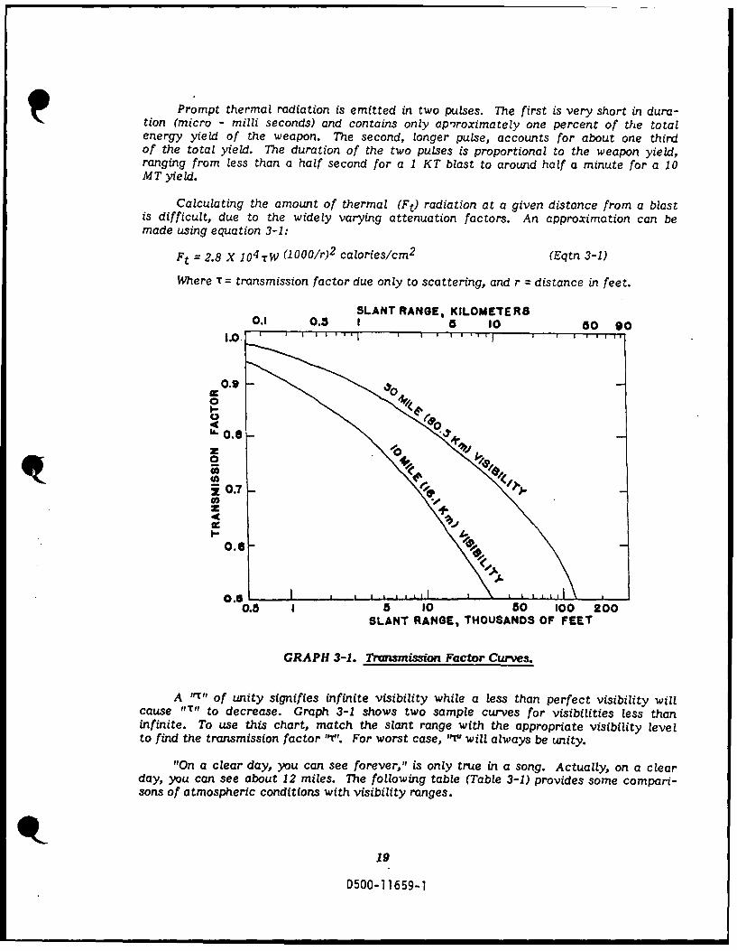
Calculating the amount of thermal (Ft) radiation at a given distance from a blastis difficult, due to the widely varying attenuation factors. An approximation can bemade using equation 3-1:
Ft = 2.8 X 10⁴ TW (1000/r)2 calories/cm2 (Eqtn 3-1)
Where T= transmission factor due only to scattering, and r = distance in feet.
SLANT RANGE, KILOMETlER80.1 0.3 I 5 10 50 90
1.0 . 1 1 ' 'I I I I I r "
0.9 _0
I-
0.8z 0
20.6
0.5-
0.5 I 5 10 50 100 200SLANT RANGE, THOUSANDS OF FEET
GRAPH 3-1. Transmission Factor Curwes.
A ,r, of unity signifies infinite visibility while a less than perfect visibility willcause IT" to decrease. Graph 3-1 shows two sample curves for visibilities less thaninfinite. To use this chart, match the slant range with the appropriate visibility levelto find the transmission factor ''. For worst case, Iqu will always be unity.
"On a clear day, you can see forever," is only true in a song. Actually, on a clearday, you can see about 12 miles. The following table (Table 3-1) provides some compari-sons of atmospheric conditions with visibility ranges.
19
D500-11659-1
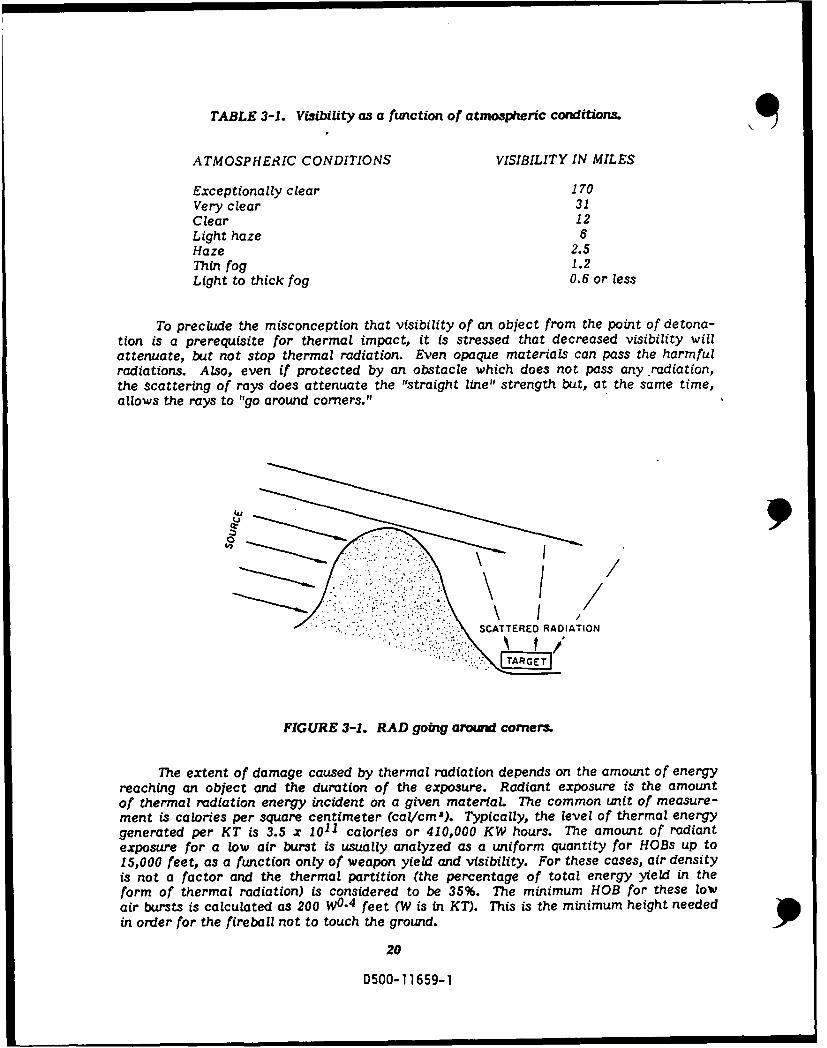
TABLE 3-1. Visibility as a function of atmospheric conditions.I\
ATMOSPHERIC CONDITIONS VISIBILITY IN MILES
Exceptionally clear 170Very clear 31Clear 12Light haze 6Haze 2.5Thin fog 1.2Light to thick fog 0.6 or less
To preclude the misconception that visibility of an object from the point of detona-tion is a prerequisite for thermal impact, it is stressed that decreased visibility willattenuate, but not stop thermal radiation. Even opaque materials can pass the harmfulradiations. Also, even if protected by an obstacle which does not pass any radiation,the scattering of rays does attenuate the "straight line" strength but, at the same time,allows the rays to "go around comers."
SCATTERED RADIATION
FIGURE 3-1. RAD going aroul comer
The extent of damage caused by thermal radiation depends on the amount of energyreaching an object and the duration of the exposure. Radiant exposure is the amountof thermal radiation energy incident on a given material The common unit of measure-ment is calories per square centimeter (cal/cm'). Typically, the level of thermal energygenerated per KT is 3.5 x 10¹¹ calories or 410,000 KW hours. The amount of radiantexposure for a low air burst is usually analyzed as a uniform quantity for HOBs up to15,000 feet, as a function only of weapon yield and visibility. For these cases, air densityis not a factor and the thermal partition (the percentage of total energy yield in theform of thermal radiation) is considered to be 35%. The minimum HOB for these lowair bursts is calculated as 200 W 0. 4 feet (W is in KT). This is the minimum height neededin order for the fireball not to touch the ground.
20
0500-11659-1
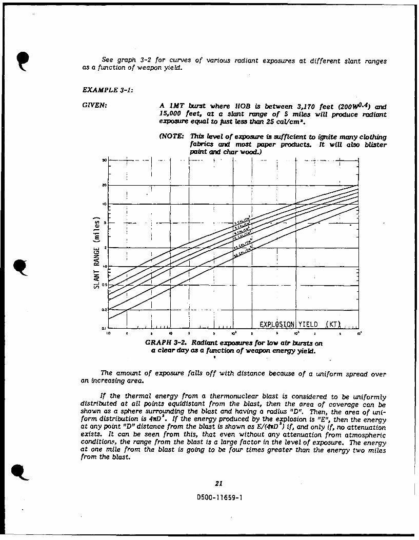
See graph 3-2 for curves of various radiant exposures at different slant rangesas a function of weapon yield.
EXAMPLE 3-1:
GIVEN: A IMT burst where HOB is between 3,170 feet (200W4. 4 ) and15,000 feet, at a slant range of 5 miles will produce radiantexposure equal to Just less than 25 cal/cm2.
(NOTE: This level of exposure is sufficient to ignite many clothingfabrics and most paper products. It will also blisterpaint and char wood.)
20
E
a 2
'a a a '0 2 S 0 IZ SI IC
GRAPH 3-2. Radiant exposures for law air bursts ona clear day as a function of weapon energy yield.
The amount of exposure falls of f with distance because of a uniform spread overan increasing area.
If the thermal energy from a thermonuclear blast is considered to be uniformlydistributed at all points equidistant from the blast, then the area of coverage can beshown as a sphere surrounding the blast and having a radius "D". Then, the area of uni-form distribution is 4irD . If the energy produced by the explosion is "E"t, then the energyat any point "D" distance from the blast is shown as E/(4irD') if, and only if, no attenuationexists. It can be seen from this, that even without any attenuation from atmosphericcondition.s, the range from the blast is a large factor in the level of exposure. The energyat one mile from the blast is going to be four times greater than the energy two milesfrom the blast.
D01
050- 059-
TECHNICAL ASPECTS OF THERMAL RADIATION
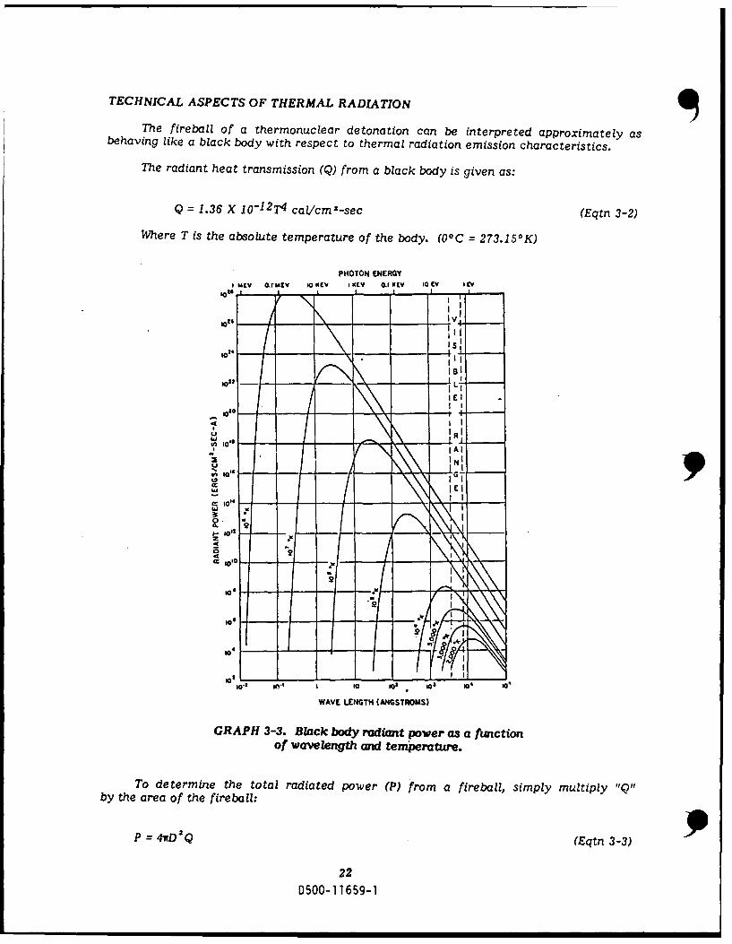
The fireball of a thermonuclear detonation can be interpreted approximately asbehaving like a black body with respect to thermal radiation emission characteristics.
The radiant heat transmission (Q) from a black body is given as:
Q = 1.36 X 10⁻¹²T4 cal/cm'-sec (Eqtn 3-2)
Where T is the absolute temperature of the body. (00 C = 273.150 K)
PHOTON ENERGYI uEV okrutv 10OKCV IKIEV Q KIEV IQ V I CV
IS
In~ IC,
2R
UE I
02
to
WAVE LENGTH (ANGSTROMS)
GRAPH 3-3. Black body radiant power as a functionof wave length and temperature.
To determine the total radiated power (P) from a fireball, simply multiply T'Q"by the area of the fireball:
P = 41tD aQ (Eqtn 3-.3)p
220500-11659-1
P = 1.71 x 10⁻¹ 1 T4 D2 cal/sec. (Eqtn 3-4)
D = Radius of fireball.
Where "T" is the absolute temperature and D is given in cm.
This equation represents the total power of all wavelengths radiated from a blackbody. Comparison curves which show the power contribution for different wavelengthsand different temperatures are shown in Graph 3-3.
Experiments have provided substantial data to use the approximations:
Pmax = 3.18W0 "5 6 kilotons/sec (Eqtn 3-5)
Where Pmax is the maximum thermal power at the time "tmax" of the secondphase maximum, and:
tmax = 0.0417 W0. 4 4 sec (Eqtn 3-6)
for HOB between 200W0 . 4 and 15,000 feet.
Calculations for bursts above 15,000 feet must take air density into account.Actual data is not abundant, but theoretical calculations indicate the following relation-ships will suffice.
3.56(W)0 . 5 9 kilotonsPmax = [p(h po]0.45 second (Eqtn 3-7)
Where "Rh)" is the ambient air density at HOB and 1.225 x 10- g/cm2 is normalsea level air density Po.
tmax = 0.038(W) 0' 4 4 [p (h)/po]0 3 6 sec. (Eqtn 3-8)
Atmospheric density ratios are provided in Table 3-2.
23
D500-11659-1

TABLE 3-2. Atmospheric Density Ratios.
Density DensityAItitude Ratio, A 1 titude Ratio,
(feet) 0(hYpo (feet) P(h)'Po
15,000 0.63 60,000 0.095
20,000 0.53 65,000 0.07525,000 0.45 70,000 0.059
30,000 0.37 75,000 0.046
35,000 0.31 80,000 0.036
40,000 0.24 85,000 0.028
45,000 0.19 90,000 0.022
50,000 0.15 95,000 0.01755,000 0.12 100,000 0.014
The two sets of equations for Pmax provide a discontinuity at 15,000 feet. Forthat altitude, both should be tried to determine which to use, based on how conservativethe calculations need be.
Thermal partition (f), the percentage of the total energy yield which is in theform of thermal radiation, varies with HOB and with total yield. The thermal partitionfor various combinations is shown in Table 3-3.
TABLE 3-3. Thermal Partition for various explosionyields at different altitudes.
Therma I Partition, f
Height of Total Yield (kilotons)Burst
(kilofeet) 1 10 100 1,000 10,000
Up to 15 0.35 0.35 0.35 0.35 0.3520 0.35 0.36 0.39 0.41 0.4330 0.35 0.36 0.39 0.41 0.4340 0.35 0.36 0.38 0.40 0.42
50 0.35 0.36 0.38 0.40 0.4260 0.35 0.37 0.38 0.40 0.4270 0.36 0.37 0.39 0.40 0.4280 0.37 0.38 0.39 0.41 0.4390 0.38 0.39 0.40 0.41 0.43
100 0.40 0.40 0.41 0.42 0.45
Thermal partition values for heights between 100,000 feet and 160,000 feet are
f 0.6. This is due to the fact that high altitude shock waves form less readily in the
thinner air nd the fireball is able to radiate thermal energy that normally at lower
24
D500-11659-1

altitudes would be transferred to hydrodynamic energy of the blast wave.
Above 160,000 feet, thermal x-rays become important and f = 0.25 at 200,000feet and remains at this value up to 260,000 feet. This results from the x-rays travelinggreater distances in the thinner air before being absorbed and therefore make no contribu-tion to the energy in the fireball.
Scaled power and time are given as P/Pmax and t/tmax, respectively.
Graph 3-4 is used to predict rate of thermal energy emission and total thermalenergy emitted at a given time independent of the yield of the explosion.
10
Q6 6__ w'-
,. W 0.4 ,.j.
0
02 I1
0 1 2 3 4 5 6 7 69 10
NORMALIZED TIME (I/,,moi)
GRAPH 3-4. Normalized power and thermal energyam a function of normalized time.(For bursts under 100,000 feet.)
Calculation of the total thermal energy, Etot, generated by a nuclear explosion,can be determined for all cases of burst height by the relationship of:
Etot = fW (Eqtn 3-9)
Where "f" is the thermal partition function and "W" is the weapon yield.
25
D500-1 1659-1
EXAMPLE 3-2:
GIVEN: A 500KT burst at an altitude of 5,000 feet.
FIND: a) The rate of emission of thermal energy.
b) The total amount of thermal energy emitted at 1 secondafter the explosion.
SOL UTION: tma = .0417 W0 4 4 sec (for bursts under 15,000 feet)
= .0417 (500)0.44 sec
= 0.64 sec
Pmax = 3.18 WO- 5 6 (for bursts under 15,000 feet)
= 3.18 (500)0.56
= 103 kilotons/sec
a) t/tmax = 1/0.64 sec (normalized time)
= 1.56 sec
from graph 3-4 at t/tma 1.56, P/Pma= : 0.59
P = 0.59 Pma,
= 0.59 X 10³ kilotons/sec
= 60.8 kilotons/sec
Using 1KT =. 1012 cal,
P = 60.8 x 10¹² cal/ec
b) from thermal partition table (3-3), f = 0.35
f = Etot/W
Etot =f W = 0.35 (500)
= 175 KT
at scaled time = 1.56,
From graph 3-4
ElEtot = 0.40
E = 0.40 X 175 70 kilotons
= 70x10 1 2 cal
26
D500-11659-1
RADIANT EXPOSURE AS A FUNCTION OF DISTANCE
If R = radiant exposure, d = slant range distance from explosion, and Etot = thermalradiation energy, then without attenuation:
R = Etot (Eqtn 3-10)
41rd
For attenuation due only to absorption in a uniform atmosphere, the attenuationfactor, e- Kd would be multiplied to the quantity R.
Where K = average absorption coefficient, averaged over the whole spectrumof wavelengths. This results in the following equation:
R = Etot e "Kd (Eqtn 3-11)
4wd2
for an exponential decay with distance.
Addition of scattering causes the attenuation factor to change with distance,visibility, and so on.
By replacing the exponential factor, e - Kd, with T where T is a complex functionof:
visibility (scattering factor)absorptiondistance
and is given in Graph 3-5 then,
R = Etot T (Eqtn 3-12)
47rda
since Etot = f W
where f = thermal partition,
then,
R = TW- (Eqtn 3-13)4wd'
and since
1KT = 1012 cal,
R (caVcm2 ) = fTW (1012) (Eqtn 3-14)~4wd'
27
0500-11659-1

Where W is in KT, and d in cm.
Other forms of this equation are:
R (cal/cm2) = 85.6 f W T (d in kilo feet), (Eqtn 3-15)
d2and,
R (cal/cm2 ) = 3.07 f W r(d in miles). (Eqtn 3-16)
d2
Graph 3-5 below, shows transmittance vaL4..s (T) for a clear day.
250 - - - - - - - - - - - - - - -
w00
00
10
5 1 0 - - - - - - -
00 50 100 150 200 250 300 350
DISTANCE FROM GROUND ZERO (KILOFEET)
GRAPH 3-5. Tranmittance, Tr, to a targeton the ground (visibility = 12 miles).
28
D500-1 1659-1
EXAMPLE 3-3:
GIVEN: A I MT blast at 28 miles from ground zero when the HOB is25,000 feet. (Asume a clear day.)
FIND: Radiant ezposure for above.
SOLUTION: Since the distance is in miles, use Equation 3-16. Next, findthe value of the thermal partition, fo. This is found in Table3-3 on page 24, and is 0.41. T can be found on Graph 3-5, andis 0.4. Putting these values into Equation 3-16 and crnching,the radiant exposure s found to be 0.64 cal/cm'.
R = 3.07(.41)(1000)(0.4) = 0.64 cal/cm"(28)2
Now, assume the same conditions except set D =14 miles
R = 3.07(.41)(1000)(0.64) = 4.11 caL/cma142
29
D500-1 1659-1

SECTION 4
BURST
X-RAYS
ALPHA AND BETAPARTICLES
NUCLEAR RADIAT/ON
The third form of energy of which a thermonuclear detonation is comprised isnuclear radiation. Nuclear radiation includes: X-rays, gamma rays, alpha and betaparticles and neutrons. Because the differences in effects from nuclear radiation aredependent upon time, nuclear radiation is categorized as initial radiation or residualradiation. Initial radiation is that which occurs during the first minute after a detonation,and residual being that which exists beyond the one minute boundary. Each of theseare explained separately in the following pages.
INITAL RADIATION
Invisible, penetrating energy, called "initial radiation" accounts for approximately3% of the total energy yield. This ionizing radiation is in the form of neutrons, gammaphotons, and fission fragments. "Prompt" is used to describe the various radiation ele-ments during the initial radiation period, e.g., prompt neutrons are those neutrons emittedduring the first minute after an explosion. The initial radiation is the only portion ofnuclear radiation which contributes to the weapon's total energy yield. Residual radiationis not a part of that measurement.
.The fission and fusion processes taking place during the explosion generate mostof the neutrons and part of the gamma rays. Alpha and beta particles are emitted duringthe radioactive decay of unfissioned uranium or plutonium or the fragments producedduring fission. Alpha and beta particles have such a short range that, generally speaking,they are not considered important in analyzing the nuclear environment threat. X-raysbehave much the same as gamma rays, and are therefore not discussed separately.
The gamma rays and neutrons are far reaching and offer the greatest threat to
30
D500-11659-1
both electronic and biological systems.
Shielding against gamma rays and neutrons is a more difficult probiem than shield-ing against thermal radiation. Due to the penetrating capabilities of each, the onlyeffective shields would be, in most cases, too thick, bulky, etc. to be practical. Asan example, 1 mile from a 1 MT blast, a 24 inch concrete barrier 'would far exceed therequirement for shielding against thermal radiation, but would pass enough nuclearradiation to be a lethal dose to humans behind the barrier. The effects of both of theseradiation forms will be discussed separately.
GAMMA RAYS
A large percentage of the prompt gammas developed during the explosion areabsorbed by the weapon material residue and only about 1 percent manage to get beyondthe blast area. However, there are other sources for the gamma rays that are a partof initial nuclear radiation. One of these "other sources is due to a neutron strikingthe nucleus of some non-fissionable material which leaves that nucleus in a high energystate. As that nucleus attempts to return to a stable state, the excess energy is thrownoff as gamma radiation. This neutron capture process yields what is termed "capturegamma rays." The process is called radiative capture.
A second source also involves the collision of a neutron with a nucleus, but inthis case, the neutron is a "fast" neutron or one having a high level of kinetic energy.Instead of neutron capture, the neutron merely transfers a portion of its energy to thenucleus, leaving the nucleus in an excited state. Once again, the energy is releasedfrom the nucleus in the form of gamma radiation. This process is known as inelasticscattering. Inelastic scattering can take place with nuclei in the weapon material orin the air.
Gamma rays are also produced through the natural radioactive decay of someof the "excited" fragments resulting from the fission reaction.
There is a time dependence of the gamma ray production which is related to thevarious half-lives of the radionuclides. Graph 4-1 shows a predicted rate of gammaenergy production as a function of time. The solid line curve is for an atmosphericburst where there would be more interaction with air and nitrogen. The dotted linecurve shows the absence of those interactions such as might be experienced in a veryhigh (exoatmospheric) burst.
31
D500-11659-1
10I I i I I I I
1029 TPROMPT
t I INCLAIIIC SCAITCRING of NCUVIRONS01 NUCLEI Of AIR AIOWS
tOl
10,"6jC ISOMC RIC DECAYS
W101
U NEUTRON CAPIUA[
IM It IN NITROCEN
z
lot I
FISSION PRODUCT
logo -
i0"
10 is
to' I I I I LI I I -, I I a f
0 tO"
10" io-
0 10to (0" I to 109
TIME (SEC)
GRAPH 4-1. Predicted gamma-ray energy, perIdloton yield, as a function of time.
In addition to time, gamma ray dose is dependent upon weapon yield and distance.As with thermal radiation, the dose will decrease with distance from the blast, accordingto the inverse square law, simply because of the larger area of coverage. Attenuationdue to scattering and absorption also applies to gamma radiation.
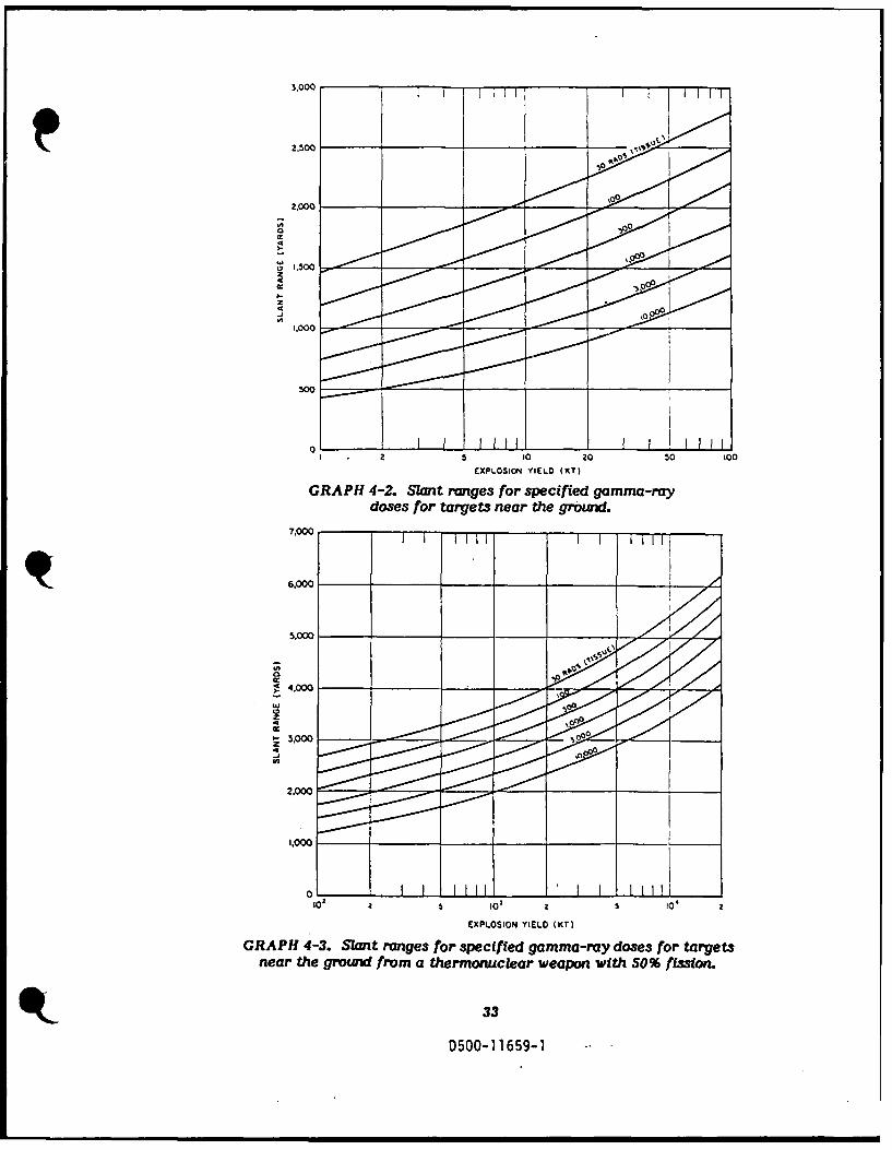
Testing and measurement of gamma radiations and computer calculations of theresults have provided enough data to predict gamma doses as a function of weapon yieldand distance from the detonation. Graph 4-2 shows various dose curves for an air burstfission device as related to slant range and yield (in kilotons). Graph 4-3 shows thesame information for a 50% fission, thermonuclear device.
The sharp increase is due to the sustained low air density following the passageof the positive phase of the shock wav, particularly for explosions of high energy yields.
Both of these graphs are based on an air density equal to 90% of normal sea levelvalue. Gamma dose will increase or decrease, according to any deviations from airdensity as calculated.
32
D500-11659-1
2,.000_
2.000
U.500
.0
2 1 0 000
EXPLOSION YIELD (KT)
GRAPH 4-2. Slant ranges for specified gamma-raydoses for targets near the groud.
7.000 1mT
6.000
c.1
z
I-3.000
2.000
i0
EXPLOSION YIELD (KT)
GRAPH 4-3. Slant ranges for specified gamma-ray doses for targetsnear the ground from a thermonuclear weapon with S0% fission.
33
D500-11659-1
SHIELDING AGAINST GAMMA RAYS
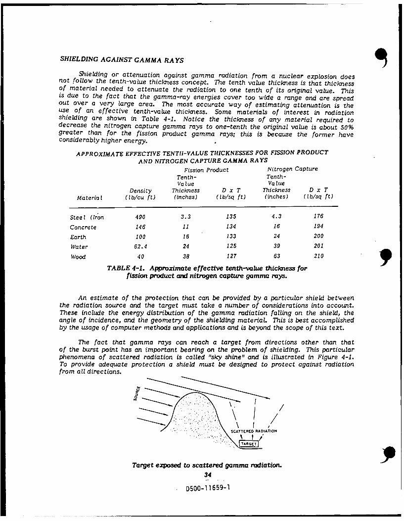
Shielding or attenuation against gamma radiation from a nuclear explosion doesnot follow the tenth-value thickness concept. The tenth value thickness is that thicknessof material needed to attenuate the radiation to one tenth of its original value. Thisis due to the fact that the gamma-ray energies cover too wide a range and are spreadout over a very large area. The most accurate way of estimating attenuation is theuse of an effective tenth-value thickness. Some materials of interest in radiationshielding are shown in Table 4-1. Notice the thickness of any material required todecrease the nitrogen capture gamma rays to one-tenth the original value is about 50%greater than for the fission product gamma rays; this is because the former haveconsiderably higher energy.
APPROXIMATE EFFECTIVE TENTII-VALUE THICKNESSES FOR FISSION PRODUCTAND NITROGEN CAPTURE GAMMA RAYS
Fission Product Nitrogen CaptureTenth- Tenth-Value Value
Density Thickness D x T Thiclness D x TMaterial (lb/cu ft) (inches) (lb/sq ft) (inches) (Ib/sq ft)
Steel (Iron 490 3.3 135 4.3 176
Concrete 146 11 134 16 194
Earth 100 16 133 24 200
Water 62.4 24 125 39 201
Wood 40 38 127 63 210
TABLE 4-1. Approximate effective tenth-value thickness forfission product and nitrogen capture gamma rays.
An estimate of the protection that can be provided by a particular shield betweenthe radiation source and the target must take a number of considerations into account.These include the energy distribution of the gamma radiation falling on the shield, theangle of incidence, and the geometry of the shielding material This is best accomplishedby the usage of computer methods and applications and is beyond the scope of this text.
The fact that gamma rays can reach a target from directions other than thatof the burst point has an important bearing on the problem of shielding. This particularphenomena of scattered radiation is called "sky shine" and is illustrated in Figure 4-1.To provide adequate protection a shield must be designed to protect against radiationfrom all directions.
0f
\ I.
SCATTEREO RAOIATION
Target exposed to scattered gamma radiation.
34
D500-11 6 59 -1

1 H+ 1 N IH+ 1+N+e-
This interaction with hydrogen (or with any substance containing hydrogen) cancause indirect ionization or excitation to occur.
Neutrons in the low to moderate speeds can produce ionization and excitationindirectly by combining (capture) with lighter isotopes.
6Li + 1 N 3 H + 2 He2
SHIELDING AGAINST NEUTRONS
Neutron shielding is a different and more difficult problem than shielding againstgamma rays. As discussed earlier, by placing. a sufficient mass of material betweenthe gamma ray source and the target, a good reduction in dosage can be obtained. How-ever, this method is not quite as satisfactory for neutron shielding. First, the veryfast neutrons must be slowed down into the moderately fast range. This requires asuitable (inelastic) scattering material, such as barium or iron. Then, the moderatelyfast neutrons have to be decelerated (by elastic scattering) into the slow range by meansof a low atomic weight element. Water is useful in this respect since hydrogen andoxygen have low atomic weights. The slow thermal neutrons must then be absorbed,which hydrogen within the water could accomplish. However, inelastic scatteringreactions of neutrons and most neutron captures result in the emission of gamma raysqwhich must be accounted for in the overall shielding scheme.
Estimates of the shielding by various structures are given in terms called a dosetransmission factor, which is the ratio of the dose received behind the shield to thedose at the same location in the absence of shielding (see Table 4-2).
InitialStructure Gamma Rays Neutrons
Three fcc[ underground 0.002-0.004 0.002-0.01Frame House 0.8-1.0 0.3-0.8Basement 0.1-0.6 0.1-0.8Multistory building(apartment type):
Upper stories 0.8-0.9 0.9-1.0Lower stories 0.3-0.6 0.3-0.8
Concrete blockhouse shelter:9-in. walls 0.1-0.2 0.3-0.512-in. walls 0.05-0.1 0.2-0.424-in. walls 0.007-0.02 0.1-0.2
Shelter. partlyabove grade:
With 2 ft earth cover 0.03-0.07 0.02-0.08With 3 ft earth cover 0.007-0.02 0.01-0.05
TABLE 4-2. Dose trunsmission factors forvarious structures.
4L. Once again, the inverse square law, absorption, scattering, and weapon yield become
35
D500-1 1659-1

2.00
2,0000
1,000
300
01 2 5 to 20 50 0
EXPLOSION YIELD (KT)CP 4PH 4-4. Slanzt ranges for specified neutron
doses for targets near the earth.
2,50
0 0
1.336
550-065-

factors in the rate of neutron dose. Graphs 4-4, and 4-5 give approximations of neutrondoses as a function of distance from the blast and the energy yield of the blast. Thefirst, is for a low air-burst from a fission device. The second is for a thermonucleardevice with 50% fission. Each is based on a 90% sea-level air density.
It is evident that the actual number of neutrons emitted per kiloton 'f e.'p!osionyield, as well as their energy distribution, may differ not only for weapons of differenttypes (fission, fusion), but also for weapons of the same kind. Therefore, these curvesthat indicate the variation of neutron dose with yield and distance cannot be correctfor all situations and reliability factors should be taken into account.
Graphs 4-4 and 4-5 may be applied to air bursts directly. For contact surfaceburst, the prompt neutron dose may be taken as one half the value for a correspondingair burst. For HOB below 300 feet, the dose may be interpolated between the valuesfor an air burst and a contact surface burst.
INITIAL RADIATION DOSE
Various methods have been found to be effective in predicting initial radiationdose with reasonable accuracy. The total initial radiation dose is composed of threetypes of radiation: neutron (Din), secondary gamma Dys, and fission products gamma(Dy f). Some example problems with accompanying graphs are included on the followingpages. All of these assume a .9 normal sea-level air density and low air burst.
This first radiation dose graph, (Graph 4-6), is a prediction of iritial neutron dosefor a fission weapon. It is scaled to a 1 kiloton burst and a HOB of 300 feet or higher.For a contact surface burst, one in which the device is detonated on the ground, a correc-tion factor of 0.5 is required. For heights between 0 and 300 feet, interpolation ofthe scaling factor should be made.
EXAMPLE 4-1:
GIVEN: A 10 KT fission weapon is exploded at a height of 300 feet.
FIND: The neutron dose at a slant range of 1,500 yards that is conserva-tive from the defensive standpoint.
SOLUTION: Since the height of burst is 300 feet, no height correction isnecessary. From the upper ("defense") curve in Graph 4-6, theneutron dose per Idloton yield at a slant range of 1,500 yardsfrom an explosion is 16 rods. The corresponding dose, D, froma 10 KT explosion is then 10 times the amont:
D = 10 X 16 = 160 rods. (tissue)
for h < 300 a correction factor must be used.
for h = 0 the correction factor is 0.5.
37
D500-11 659-1

10
103 10'I
0 10
10 1074
SS
30" 3I
Z
I-A2 5
S -
0 1,000 2Po 3.000 4,000
SLANT RANGE FROM EXPLOSION (YARDS)
GRAPH 4-6. Initial neutron dose per Idloton from fission device.
It is suggested that the upper curve be used to obtain a conservative estimateof the neutron dose from fission weapons for defensive purposes and that the lowercurve be used for a conservative estimate for offensive purposes.
For a contact surface burst, the values in Graph 4-6 and 4-7 should be multipliedby 0.5 and can be linearly interpolated to HOB of 300 feet where the exact graph valuecan be used.
The next graph is also a prediction of initial neutron dose. The only difference
is that Graph 4-7 is for a 50% fission thermonuclear device.
38
D500-11659-1

-0 1 __1I -
1 0
10 ,I -
10 104
2 --- _
-' IO
S -----
Z
o
SLAN RAG RO-XLOIN(YRS
fro a hroncereie
l-
ls -- --- " -_------- 3
01,0030 2,000 3,000 4.000
SLANT RANGE FROM EXPLOSION (YAROS)
GRAPH 4-T. Initial neutron dose per kilotonfrom a thermonuclear device.
The following example, and graphs 4-8 and 4-9 are used for finding the secondarygamma contribution to initial radiation dose. They are also scaled to 1KT and 300 feet.
EXAMPLE 4-2:
GIVEN: A 20 KT fission weapon is exploded on the surface (contact surfaceburst).
FIND: The secondary gamma-ray dose at a slant range of 1,000 yardsthat is conservative from the offensive standpoint.
SOLUTION: Since this is a contact surface burst, a correction factor of 0.5must be applied to the value obtained from graph 4-8. Fromthe lower ("offense") curve in Graph 4-8, the secondary gamma-raydose per kiloton yield at a slant range of 1,000 yards from anexplosion at or above 300 feet is 30 rods. The correspondingdose, D, from a surface burst 20 KT explosion is:
D(total dose) = 20KT X 0.5 X 30 rfds.= 300 rods.
39
0500-11659-1

103
- \ \. -S4 .s
10 3 10 D
10 t
Iot
$ $
o 1I \\-
0 1.000 2000 1000 4000'
SLANT RANGE; FROM EXPLOSION (YARDS)
GRAPH 4-8. Air-secondary gamm-ray component of initial radiationas a function of slant range for a fission weapon."
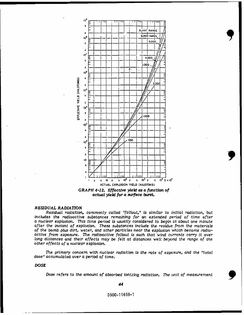
The third factor in initial radiation dose, fission product gamtna dose, is calculatedas using graphs 4-10 and 4-11, or 4-12.Graph 4-11 is used to find the effective yield of a low air fission weapon. Graph4-12 is for a surface burst. The effective yield is then used with graph 4-10 to find.the fission product gamma-ray component.
EXAMPLE 4-3:GIVEN: A 20 KT fission weapon Is exploded on the surface (contact surface
FIND: Thie fission product gamma-ry dose at a slant range of 1,000yards.
0
aD5- 11659-1-
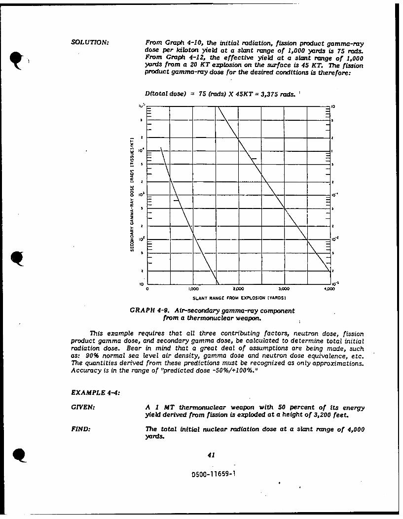
SOLUTION: From Graph 4-10, the initial radiation, fission product gamma-raydose per kiloton yield at a slant range of 1,000 yards is 75 rads.From Graph 4-12, the effective yield at a slant range of 1,000yards from a 20 KT explosion on the surface is 45 KT. The fissionproduct gamma-ray dose for the desired conditions is therefore:
D(total dose) 75 (rads) X 45KT = 3,375 rads.
,1 "
o a trnl weapon
from a hroula epn
This example requires that all three contributing factors, neutron dose, fissionproduct gamma dose, and secondary gamma dose, be calculated to determine total initialradiation dose. Bear in mind that a great deal of assumptions are being made, suchas: 90% normal sea level air density, gamma dose and neutron dose equivalence, etc.The quantities derived from these predictions must be recognized as only approximations.Accuracy is in the range of "predicted dose -50%1+100%."
EXAMPLE 4-4:
GIVEN: A I MT thermonuclear weapon with 50 percent of its energyyield derived from fission is exploded at a height of 3,200 feet.
FIND: he total initial nuclear radiation dose at a slant range of 4,000yards.
41
D500-11659-1
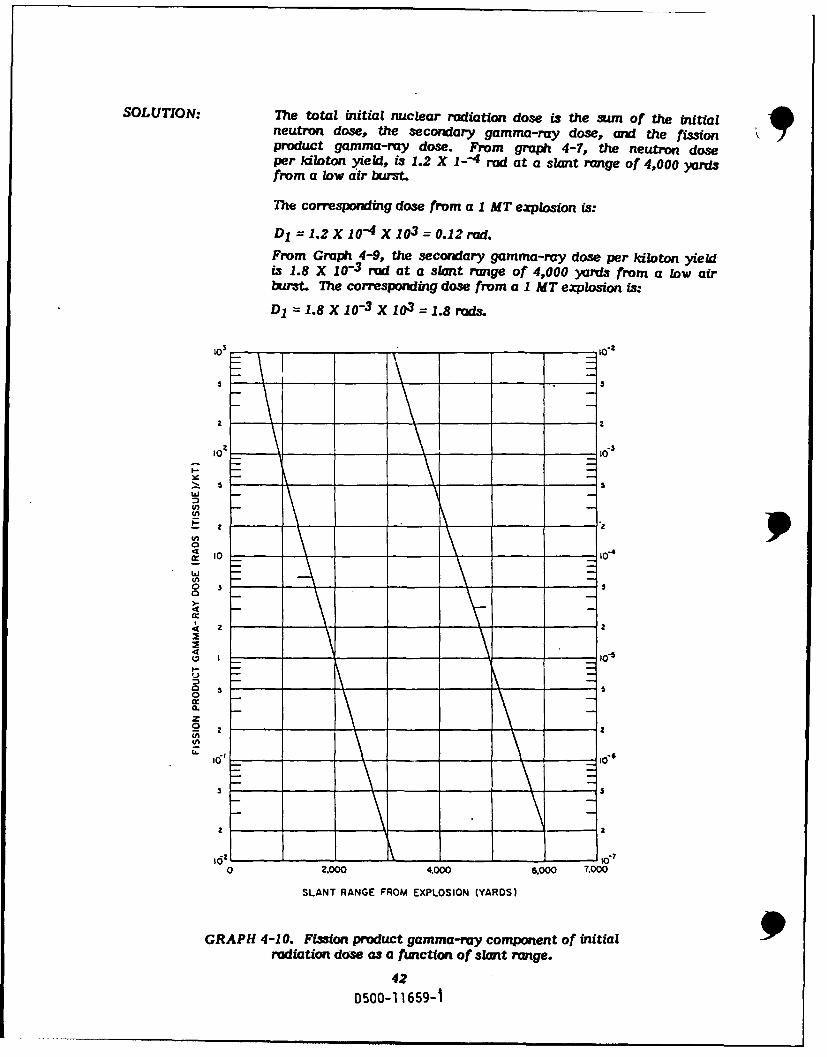
SOLUTION: The total initial nuclear radiation dose is the sum of the initialneutron dose, the secondary gamma-ray dose, and the fissionproduct gamma-ray dose. From graph 4-7, the neutron doseper kiloton yield, is 1.2 X 1--4 rod at a slant range of 4,000 yardsfrom a low air burst.
The corresponding dose from a 1 MT explosion is:
D1 = 1.2 X 10-4 X 10 3 = 0.12 Fad.
From Graph 4-9, the secondary gamma-ray dose per lokiton yieldis 1.8 X 10⁻³ rod at a slant range of 4,000 yards from a low airbust. The corresponding dose from a 1 MT ezplosion is:
D1 1.8 X 10-3 X 103 = 1.8 rods.
105
I-1
5 5
w
10 , io-4
10-
~ 0
o s s
Sz
0
o I
I-
.z
I ___0"
_$
___ _
S S
2o 2
0 2.000 4000 6,000 T,000
SLANT RANGE FROM EXPLOSION (YARDS)
GRAPH 4-10. Fission product gamma-ray component of initialradiation dose as a function of slant range.
42
0500-11 659-1

From Graph 4-10, the fission product gamma-ray dose per kilotonfission yield at a slant range of 4,000 yards from the explosionis 3.2 X 10⁻⁴ rod. The height of burst, 3,200 feet, is sufficientlyclose to the scaled height of 200 W. 4 , i.e., 3,170 feet, that graph4-11 should provide an accurate value of the effective yield.From graph 4-11, the effective yield at a slant range of 4,000yards from a low air burst 1 MT explosion is 4 X P KT (or 40MT). Since only 50 percent of the total yield is derived fromfission, a correction factor of 0.5 must be applied. The fissionproduct gamma-ray dose is:D2 = 0.5 X 3.2 X 10-4 X 4 X 104 = 6.4 rod.
The total initial nuclear radiation dose is:D = D O +D +D 2
= 0.12 + 1.8 + 6.4= 8.3 rods.
3
SLANT RANGE
O g.006YAROS
4,00 0
o--J - - - - - - - -
50 - - -- - --- -z 2000
I.
0
i-. 2 - - - - - - - - - -
_ 0 5
SI0 S- -- -- 0- - -o -
-/
W
'I --
,033
5
10- 65 -
502 5 X a
50 - -D500-115-1--- 1-
10 -1 1 rr H, •rr r i mw-rll i-1 iii
SLANT RANGE
0 6.000 YARDS
.. 5.0
.000)
2 -- - - - - . - - -106
zI-Z
0 2.000 _
0
o Z
-JI
t,. /,oo
1.000
2
10 - 2 0
ReI II 0all ll ou, I s i i t aACTUAL EXPLOSION YIELD (KILOTONS)
GRAPH 4-12. Effective yzel as a fwnction ofactual yield for a surface hurst.
RESIDUAL RADIATIONResidual radiation, commonly called "fallout," is similar to initial radiation, but
includes the radioactive substances remaining for an extended period of time aftera nuclear explosion. This time period is usually considered to begin at about one minuteafter the instant of explosion. These substances include the residue from the materialsof the bomb plus dirt, water, and other particles near the explosion which become radio-active from exposure. The radioactive fallout is such that wind currents carry it overlong distances and their effects may be felt at distances well beyond the range of theother effects of a nuclear explosion.
The primary concern with nuclear radiation is the rate of exposure, and the "totaldose" accumulated over a period of time.
DOSE
Dose refers to the amount of absorbed ionizing radiation. The unit of measurement 944
D500-11659-1

for dose is the rad. One rod is the measure of absorption of 100 ergs of radiation pergram of absorbing substance and 1 erg is equal to 10f Joules. Dose rate is the amountof absorbed radiation per unit time commonly referred to as rads per hour.
A dose rate nomograph can be used for calculating approximate dose rates, giventhat a unit-time reference value is known. A dose rate nomograph is shown in Graph4-13, below:
1.000 1.000
700 700
400 -400
200 - 200
UNIT-TIME REFERENCE100 DOSE RATE (RAOS/HR) .'100
70 10,000 -707,000
40 4,000 "402.000
1.00020 700 -20
DOSE RATE 400 TIME
(RADS/HR) 10 200 (HR)
10101007 70 -7
40
4- 20 4
107
2. 4 -2
2
1. 1 1I0.7
0.71 0.4 0.7
0.2
0.4 0.1 -0.4
0.070.04
0.2 "0.20.02
0.010.11 .0.1
GRAPH 4-13. Dose Rate Nomograph.
EXAMPLE 4-5:
GIVEN: A dose rate is known to be 8 rods per hour, 6 hours after a nuclearexplosion.
FIND: (a) the dose rate 24 hours after the burst.(b) the t me after the burst at which the dcse rate is 1 rad/hour.
SOLUTION: First, establish the unit-time reference dose rate on the nomograph
45
D500-11659-1

by connecting the "8" on the dose rate line with the "60 on thetime line with a straight line. The reference number as readfrom the unit-time reference dose rate line is "69." To findthe dose rate 24 hours after the burst, draw another straightline from "24" on the time line, through the reference "69," andacross to the dose rate line. Read "1.5" as the dose rate at thepoint of intersection. A third straight Line from 1 rad/hr., throughreference "69" and to the time line. Where the intersectionoccurs, read 34 hours.
1.000-- 1.000
700 700
400 400
200-' 200
UNIT-TIME REFERENCE100 ' OOSE RATE (RA0S/HR) 100
70 10.000 707.000
40. 4,000 402,000
20-, 1.00020-700 •20
DOSE RATE 400 TIME(RADS/HR) 10- 10 R)
7- 7
410I
2-4 2.2
'0.070.7-- 0.04- .
0.2.
0.07
0.1 0.041.0.0.2
GRAPH 4-14. Dose Rate Nomograph.
DELAY OF RADIATION
Graphs 4-15 and 4-16 show the time dependence of the exposure dose. rate. Thefirst graph covers the period of time between one tenth of an hour and 1000 hours fol-lowing a detonation. The second graph covers 100 hours through 1 million hours (roughly115 years). There are two curves shown on the graphs. The solid line shows the predictedrate based on complex calculations which is not within the scope of this text. The dashed
46
D500-11659-1

line is just a straight line approximation from KT -1 "2 where "K" is the normalized rateat 1 hour after the explosion and "t" is the time, in hours, following the explosion.
IIW 10' • [-
4 - -\ . . ..- - -
,I ,,, - - - - - --
",,,, - -
-U- \ W -
4 Z L
4, ,',O , i ,., :" , I !
W. WU
c-c W I"j4 z a- - - -,- - - --
- - - I.,
IC ,"- - - - - . - . \-' , ,---
-7 M \J 1 ? 0 i ~ I
IDAY IWK a -- "tO", 1 .1 I i , I . 1. .... ill 6 MO I YR 525YR ooYR
10. I 0 4 r to 2 2 7 10 i0"
_ 4 ', I I ]III I -- A " 414d
TIME AFTER EXPLOSION (HOURS) '2 10 4 T OC , ?iOs
4 e
TIME AFTER EXPLOSION (HOURS)
GRAPHS 4-15 and 4-16. Time dependence of nuclearradiation dose rate.
Each curve in these graphs uses a unity factor for t = 1 hour. The value read fromthe graph for a given time would therefore be a multiplier for the actual dose rate atone hour after the explosion. It can be seen on Graph 4-16 that the straight line approxi-mation does not fall off as rapidly as the more closely approximated curve startingat about the four month time frame.
Another way to approximate the dose rate is called the "sevenfold rule." It statesthat for each multiple of seven hours from the explosion time, a decade decrease indose rate will occur. The following equation shows this expression:
Kn = 0.1nK 0 when t = 7n hours (Eqtn 4-1)
Where K0 is the dose rate at one hour after explosion, Kn is the new dose rate,and n =1, 2, 3 & 4. For time, t = 7n hours.
The next graph (Graph 4-17) is used in conjunction with Graphs 4-15 and 4-16to calculate the total dose accumulated over a given period of time after entering acontaminated area.
47
D500-11659-1

I0 , T ri * r 9** I .jq
0 W0-
o 6 -' --
C,,>
4W
_ _ • ,. . ._'_
I-
I MM I MIN Z0OMIN DY' IWE
0* ' 10 ,I I I 10 ,, I ,J
TIME AFTER EXPLOSION (HOURS)
GRAPH 4-17. Curve for calculating total accumulated dose. 9
In order to use this graph, the dose rate at the time of entering the contaminatedarea and the length of stay must both be 1onown.
To explain the use of this graph, the following example will be calculated:
EXAMPLE 4-6:
GIVEN: Suppose an individual becomes exposed to a certain quantityof radiation 2 hours after a nuclear explosion and the dose rate,measured at that time, is found to be 1.5 rads/hr
FIND: The total dose accumulated during the subsequent 12 hours, i.e.,by 14 hours after the explosion? The first step is to determinethe wuait -time reference dose rate. From Graph 4-15 it is seenthat:
SOLUTION: Dose rate at 2 hours after explosion = 0.40Unit-time reference dose rate
and, since the dose rate at 2 hours is blown to be 1.5 rad s/br,the reference value is 1.5/0:40 = 3.8 rosb. Next, from Graph4-17, it is found that for 2 hours and 14 hours, respectively, after
48
D500-1 1659-1
M I

the explosion:
Accumulated dose at 14 hours after explosion = 7.1Unit-time reference dose rate
Accumulated dose at 2 hours after explos3ion _ 58Unit-time reference dose rate
Hence, by subtraction:
Accumulated dose between 2 and 14 hours after explosion = 1.3Unit-time reference dose rate
7.1 - 5.8 = 1.3
The unit-time reference dose rate is 3.8 rads/hr, and so the ac-cumulated dose received in the 12 hours, between 2 and 14 hoursafter the explosion, is 3.8 X 1.3 = 4.9 reds.
The total accumulated radiation dose received from early fallout during any speci-fied exposure in a contaminated area can be estimated if the dose rate at some definitetime after the explosion is Iown. Also, the time can be calculated for commencingan operation requiring a specified stay in a defined total radiation dose.
On the following pages, examples are provided to illustrate the use of two additionalgraphs (Graphs 4-18 and 4-19,' for calculating total radiation dose.
49
D500-11659-1

ENTRY TIME (DAYS AFTER EXPLOSION)
0.1 0.5 1 2 3 5 10 30 60 ye
0
- 7 I
LL.
o 2E
,o- 2 \ T \ • ''. .o I , X\
z\
10 " 4 7 I 2 4 7 to 2 4 7 102 2 4 7 10 4 7 10 4
ENTRY TIME (HOURS AFTER EXPLOSION )
GRAPH 4-18. Curves for calculating total accumulated
dose, based on unit-time reference dose rate.
EXAMPLE 4-7:
GIVEN: The dose rate at I hours after a nuclear explosion is 6 fads/hr.
FIND: (a) The total accumulated dose received during a Period of2 hours commencing at 6 hours after the explosion.
(b) 7he time after the explosion when an operation requiringa stay of 5 hours can be started if the total dose is to be4 rads.
SOLUTION: 7he first step is to determine the unit-time reference dose rate(RI). From Graph 4-13, a straight line connecting 6 ashon the left scale with 4 hours on the right scale intersects themiddle scale at 32 radls/hr, this is the value of R1.
(a) Enter Graph 4-18 at 6 hours after the explosion (horizontalscale) and move up to the curve representing a time ofstay of 2 hours. 7Te corresponding reading on the verticalscale, which gives the multiplying factor to convert RIto the required total dose, is seen to be 0.19. Hence, the ]accumulated dose is: 1
so
D500-11659-1

0.19 X 32 = 6.1 reds.
(b) Since the accumulated dose is given as 4 rods and R1 is32 rads/hr, the multiplying factor is 4/32 = 0.125. EnteringGraph 4-18 at this point on the vertical scale and movingacross until the (interpolated) curve for 5 hours stay isreached, the corresponding reading on the horizontal scale,giving the time after the explosion, is seen to be 21 hours.
ENTRY TIME (DAYS AFTER EXPLOSION)
0.1 0.5 I 2 3 5 10 30 60 1 yr
7 EXPOSURE TIME "
-0 4 -- A
U OAI
0
I0I
z . 0 20-
Io~ m-OUR S!
ENTRY TIME 4 HOURS
GRAPH'4-1.uvefocacltntoaacu ltd
'€[ ' -- 2 HOURS2I0I s tabe a fu g b
w 7 r es t a u a b o t u
I" 12 PA INUTES
trt min0 ter.TerfrI
hr may b a cng ini t qunit fl alota
a givenlocationnduringrthe timeiof exposure.
GItN Upesnta oneteng a cotamiaesd aireagate12ahours afdte ncaleuar10-1 1D0- 1659-110
tions of radiation dose rates, and doses in which they are used, are based on the assump-tion that a target is exposed to a certain quantity of early fallout and remains exposedcontinuously (without protection) to this same quantity for a period of time. In an actualfallout situation, these conditions probably would not exist. Shelters would attenuateradiation and weather conditions will disperse fallout particles in some areas and concen-trate them in others. Therefore, there may be a change in the quantity of fallout ata given location during the time of exposure.
EXAMPLE 4-8:
GIVEN: Upon entering a contaminated area at 12 hours after a nuclear
51
D500-11659-1

explosion, the dose rate is 5 rads/hr.
FIND: (a) The total accumulated radiation dose received for a stayof 2 hours.
(b) The time of stay for a total accumulated dose of 20 rads.
SOLUTION: (a) Start at the point on Graph 4-19 representing 12 hoursafter the explosion on the horizontal scale and move upto the curve representing a time of stay of 2 hours. Themultiplying factor for the dose rate at the time of entry,as read from the vertical scale, is seen to be 1.9. Hence,the total accumulated dose received is:
1.9 X S = 9.5 rads.
(b) The total accumulated dose i3 20 rads and the dose rateat the time of entry is 5 radshr, hence, the multiplyingfactor is 20/5 = 4.0. Enter Graph 4-19 at the pointcorresponding to 4.0 on the vertical scale and movehorizontally to meet a vertical line which starts from thepoint representing 12 hours after the explosion on thehorizontal scale. The two lines are found to intersect ata point indicating a time of stay of about 4 1 hours.
952
D500-1 1659-1

BSECTION 5
/ATMOSPHERE
BASIC ELECTROMAGNE77C THEORY
In order to better grasp the sections to follow, a. very brief, general discussionof electromagnetic field theory is required. There are basically only 4 topics that needto be reviewed; vectors, electric fields, magnetic fields, and the combined electromag-netic fields.
VECTORS
A vector is a quantity that has both magnitude and direction associated with it.This differs from the scalar, in that the scalar only describes the magnitude of properties,and is independent of the direction. Vectors are geometrically represented by arrows,
~whose length indicates magnitude and whose orientation indicates direction. They can
be represented in any coordinate system, but for this text will only be presented inthe cartesi.an coordinate system. Vectors may be separated into individual components,each showing one coordinate direction and its corresponding magnitude. Vectors areuseful in simplifying the abstraction associated with the behavior of electromagneticfields.
ELECTRIC FIELDS
In 1784, Augustine de Coulomb studied the interacting forces between two pointcharges. By moving a "test point charge" about a fixed charge, he could measure exertedforces on the test charge. The well known phenomenon can be explained by statingthat within a vicinity of any charge, there exists a medium of electric field. This electricfield exerts forces on charges within the field, in proportion to the magnitude of charges,and inversely proportional to the square of distance between them.
The electric field is said to exist at a:point, if a force of electrical origin is exerted
on a stationary charged body placed at that point.
Michael Faraday introduced the concept of field lines to represent the electricfield. The field lines are imaginary lines drawn in uch a way that their direction atany point is the same as the direction of the field at that point. The magnitude of thefield is proportional to the number of field lines per unit area crossing a surface atright angles to the direction of the field.
D)500-1 1659-1
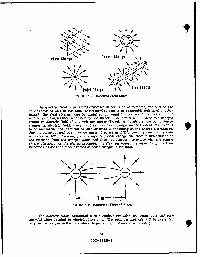
Plane Charge Sphere Charge
Point Charge A Line ChargeFIGURE 5-1. Electric Field.Lines.
The electric field is generally expressed in terms of volts/meter, and will be theonly expression used in this text. (Newtons/Coulomb is an acceptable unit used in othertexts.) The field strength can be explained by imagining two point charges with a 1volt potential difference separated by one meter. (See Figure 5-2.) These two chargescreate an electric field of one volt per meter (iV/m). Although a single point chargecreates an electric field, there must be additional charge located where the field isto be measured. The field varies with distance R depending on the charge distribution. pFor the spherical and point charge cases, it varies as 1/R2. For the line charge caseit varies as I/R. However, for the infinite planar charge the field is independent ofthe distance from the charged plane and does not decrease inversely with the squareof the distance. As the charge producing the field increases, the intensity of the fieldincreases, as does the force exerted on other charges in the field.
10
FIGURE 5-2. Electrical Field of 1 VIM
The electric fields associated with a nuclear explosion are tremendous and veryharmful when coupled to electrical systems. The coupling methods will be presentedlater in the text, as well as procedures to protect against unwanted coupling.
54
0500-11659-1
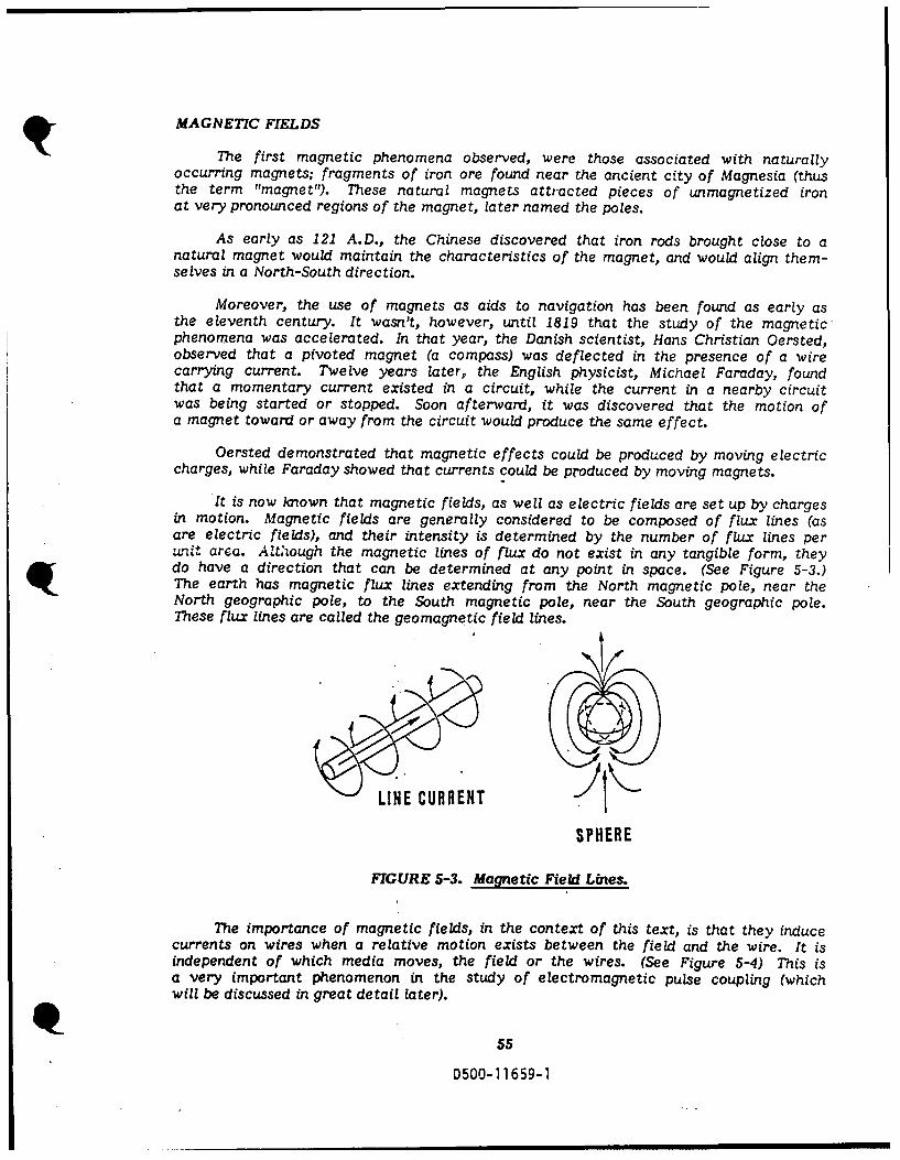
MAGNETIC FIELDS
The first magnetic phenomena observed, were those associated with naturallyoccurring magnets; fragments of iron ore found near the ancient city of Magnesia (thusthe term "magnet"). These natural magnets attracted pieces of unmagnetized ironat very pronounced regions of the magnet, later named the poles.
As early as 121 A.D., the Chinese discovered that iron rods brought close to anatural magnet would maintain the characteristics of the magnet, and would align them-selves in a North-South direction.
Moreover, the use of magnets as aids to navigation has been found as early asthe eleventh century. It wasn't, however, until 1819 that the study of the magneticphenomena was accelerated. In that year, the Danish scientist, Hans Christian Oersted,observed that a pivoted magnet (a compass) was deflected in the presence of a wirecarrying current. Twelve years later; the English physicist, Michael Faraday, foundthat a momentary current existed in a circuit, while the current in a nearby circuitwas being started or stopped. Soon afterward, it was discovered that the motion ofa magnet toward or away from the circuit would produce the same effect.
Oersted demonstrated that magnetic effects could be produced by moving electriccharges, while Faraday showed that currents could be produced by moving magnets.
It is now known that magnetic fields, as well as electric fields are set up by chargesin motion. Magnetic fields are generally considered to be composed of flux lines (asare electric fields), and their intensity is determined by the number of flux lines perutnit area. Although the magnetic lines of flux do not exist in any tangible form, theydo have a direction that can be determined at any point in space. (See Figure 5-3.)The earth has magnetic flux lines extending from the North magnetic pole, near theNorth geographic pole, to the South magnetic pole, near the South geographic pole.These flux lines are called the geomagnetic field lines.
LINE CURRENT
SPHERE
FIGURE 5-3. Magnetic Field Lines.
The importance of magnetic fields, in the context of this text, is that they inducecurrents on wires when a relative motion exists between the field and the wire. It isindependent of which media moves, the field or the wires. (See Figure 5-4) This isa very important phenomenon in the study of electromagnetic pulse coupling (whichwill be discussed in great detail later).
55
0500-11659-1

jx x x x:-x XeX X Moving WireOx', X ×
Stationary Field
Moving Field
Stationary Wire
FIGURE 5-4. Relatve motion induces currents.
ELECTROMAGNETIC FIELDS
An electromagnetic field is a combination of electric and magnetic fields, withthe electric lines of force perpendicular to the magnetic lines of force at all pointsin space. (See Figure 5-5.) As this "plane wave" propagates through space, it movesin a direction perpendicular to both the electric and magnetic components.
Propagating electromagnetic fields are produced when charged particles are sub-jected to acceleration. The most familiar example of an accelerating charged particle,is an electron in a conductor carrying an alternating current. Since the electron's velocityis constantly changing, a fluctuating magnetic field is generated, resulting in a propagat-ing electromagnetic field outward from the conductor. The frequency of the field isthe same as the frequency of the alternating current in the conductor.
Radiated electromagnetic fields will be considered to be plane waves in the re-mainder of this text. A plane wave is simply a propagating field, which is uniform overany plane, perpendicular to the direction of propagation.
There are many forms of an electromagnetic field, from visible light and infraredrays, to gamma rays, x-rays, radio waves, and the major concern of this text, electromag-netic pulse from a nuclear explosion.
DD5O0-1 1659-1

E
FIGURE 5-5. Electromagnetic Fields.
GENERAL THEORY
The electromagnetic pulse (EMP) is a very harmful and often little noticed effectof a nuclear detonation. It is roughly comparable to the electromagnetic fields associatedwith lightning, but with several significant differences. It is a narrow pulse with a veryfast rise time (generally a few nanoseconds), while a lightning pulse is much wider (2orders of magnitude), and has a slower rise time (approximately 1-5 microseconds).EMP is on the order of 50,000 V/m, while lightning is roughly 100 to 1000 V/m, andthe area of coverage from EMP is very large and capable of covering the entire UnitedStates, where that of a lightning strike is confined to a small, localized area.
Operating regions for the purpose of EMP analysis are categorized as: Ground, loweratmosphere (less than 20 kin), upper atmosphere (20-50 kn), and exoatmosphere (greaterthan 50 kin).
57
D500-1 1659-1

MAJOR DIFFERENCES BETWEEN LIGHTNING tAND ELECTROMAGNETIC PULSE
ELECTROMAGNETIC PULSE LIGHTNING
Narrow Pulse (1 to 2 microseconds) Wide pulse (hundreds of microseconds)Very fast rise time (nanoseconds) Slow rise time (1 to 5 microseconds)Large amplitudes (50,C00 Small amplitudes (100 to 1000volts/meter) volts/meter)Large area of coverage (possibly Small area of coverage (very localizedentire U.S.) area)Large frequency spectrum Small frequency spectrum
EMP can have a very harmful effect, even at altitudes where there are no otherappreciable weapon effects. In fact, the most harmful EMP comes from high altitudebursts where the blast, shock, and thermal radiations are unnoticeable on the earth.
EMP is most harmful to devices which use integrated circuits, semiconductors,or other solid state circuitry. Digital computers, intercom systems, and electronicsensors are but a few of those devices. Devices which use vacuum tubes and inductors,rather than solid state electronics are much less susceptible to the EMP, but can stillbe damaged. Power supplies and transmitters or receivers fall into .this categor-,. Alsosomewhat susceptible are devices which use low current switches, relays, and meters,such as: life support systems, panel indicators, status boards, and power distributionsystems, all of which can be found to some extent on Military aircraft. Many devices,however, are not susceptible to EMP. These include those devices which are designedfor high power, high current operation, such as transformers, and motors. These devicesare capable of withstanding the EMP without any added protection.
DEGREE OF SUSCEPTIBILITY TO EMP
VERY SUSCEPTIBLE NOT AS SUSCEPTIBLE NOT SUSCEPTIBLE
DEVICES THAT USE: DEVICES THAT USE: DEVICES THAT USE:
- INTEGRATED CIRCUITS - VACUUM TUBES AND - HIGH CURRENT/HIGH- SEMICONDUCTORS INDUCTORS POWER OPERATION, SUCH
OTHER SOLID STATE - LOW CURRENT AS TRANSFORMERS ANDCOMPONENTS SWITCHES MOTORS
- LOW CURRENTRELAYS AND METERS
EMP from a nuclear detonation is divided into the following three regions: burst,source, and radiating. (See Figure 5-6.)
958
D500-11659-1

___ BURST --------
SOURCE
....... .
q.FIGURE 5-6. Detonation Regions.
The Burst region is where the blast initiates. This is, for HEMP, at or aboveapproximately 40 km.
The deposition source region is where approximately all of the gamma rays willbe absorbed and EMP generated.
The accompanying diagram (Graph 5-1) shows how the source region varies withboth weapon yield and height of burst. The cross sections shown are for weapon yieldsof I and 1OMT, with various burst heights. These curves were computed from estimatedgamma-ray emissions from the explosions and the kcnown absolution coefficients ofthe air at various altitudes. The deposition region is thicker at small ground distancesfrom ground zero, i.e. immediately below the burst and then thins as the ground distanceincreases.
The third region is the radiating region. The radiating region has 3 generalcharacteristics: 1) The direction of propagation is radially outward from the burst;2) The electric field and the magnetic field vectors are in a plane perpendicular tothe direction of propagation; and 3) The fields have a far-field range dependence of11R. (See Figure 5-7).
59
D500-1 1659-1

SOURCE REGION FCR HEMPFOR VA"IOUS BURST HEIGHTS
70S60 so-T
0 - HOB-50 KM ROB-100 HOB 200 HOB-300 KM0-
0 JoL , p I i i I
0 200 400 600 800 1000 1200 1400
DISTANCE PARALLEL TO SURFACE (KM)
90 10 MT
70
0.H-100 KM HQB-200 Km HOB-300 Km
10-
06o 800oo 1o00 1200 500
DISTANCE PARALLEL TO SURFACE (KM)
GRAPH 5-1. Source region for HEMP for various burst heights.
E M P BEHAVES LOCALLY AS A PLANE WAVEB
DIRCTION Of PROPOGATION{AA I ALLT OUTWARD)
POII|T OF OSSZlVATION
FIGURE 5-7. Propagation of EMP.
60
D500-11659-1
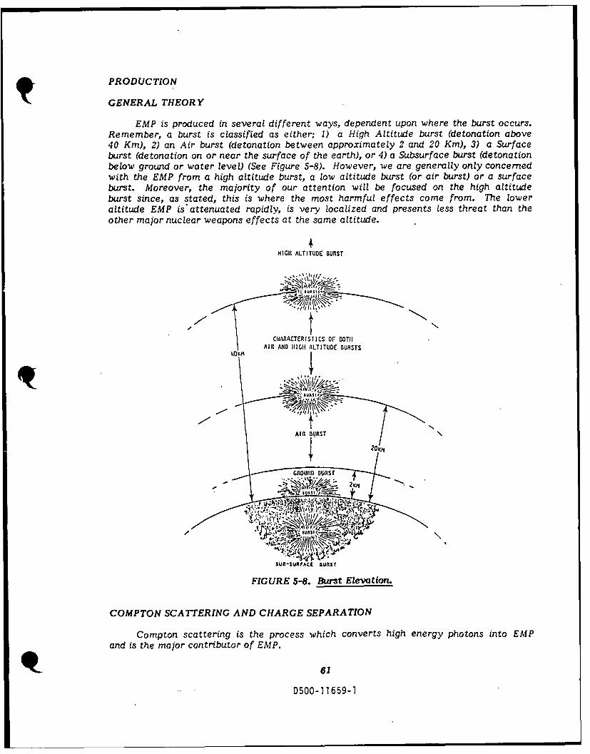
PRODUCTION
GENERAL THEORY
EMP is produced in several different ways, dependent upon where the burst occurs.Remember, a burst is classified as either; 1) a High Altitude burst (detonation above40 Kin), 2) an Air burst (detonation between approximately 2 and 20 Kin), 3) a Surfaceburst (detonation on or near the surface of the earth), or 4) a Subsurface burst (detonationbelow ground or water level) (See Figure 5-8). However, we are generally only concernedwith the EMP from a high altitude burst, a low altitude burst (or air burst) or a surfaceburst. Moreover, the majority of our attention will be focused on the high altitudeburst since, as stated, this is where the most harmful effects come from. The loweraltitude EMP is attenuated rapidly, is very localized and presents less threat than theother major nuclear weapons effects at the same altitude.
4HIGH ALTITUDE BUIST
CHIARACTERISTICS OF BOTHAIRl AIO HIGH ALTITUDE BURSTS
':'"
AUIURAC BURS
I-GROUND UST
and" SUIIIF iis t a o u f
FIGURE 5-8. Burst Elevation.
COMPTON SCATTERING AND CHARGE SEPARATION
Compton scattering is the process which converts high energy photons into EMPand is the major contributor of EMP.
61
0500-11659-1
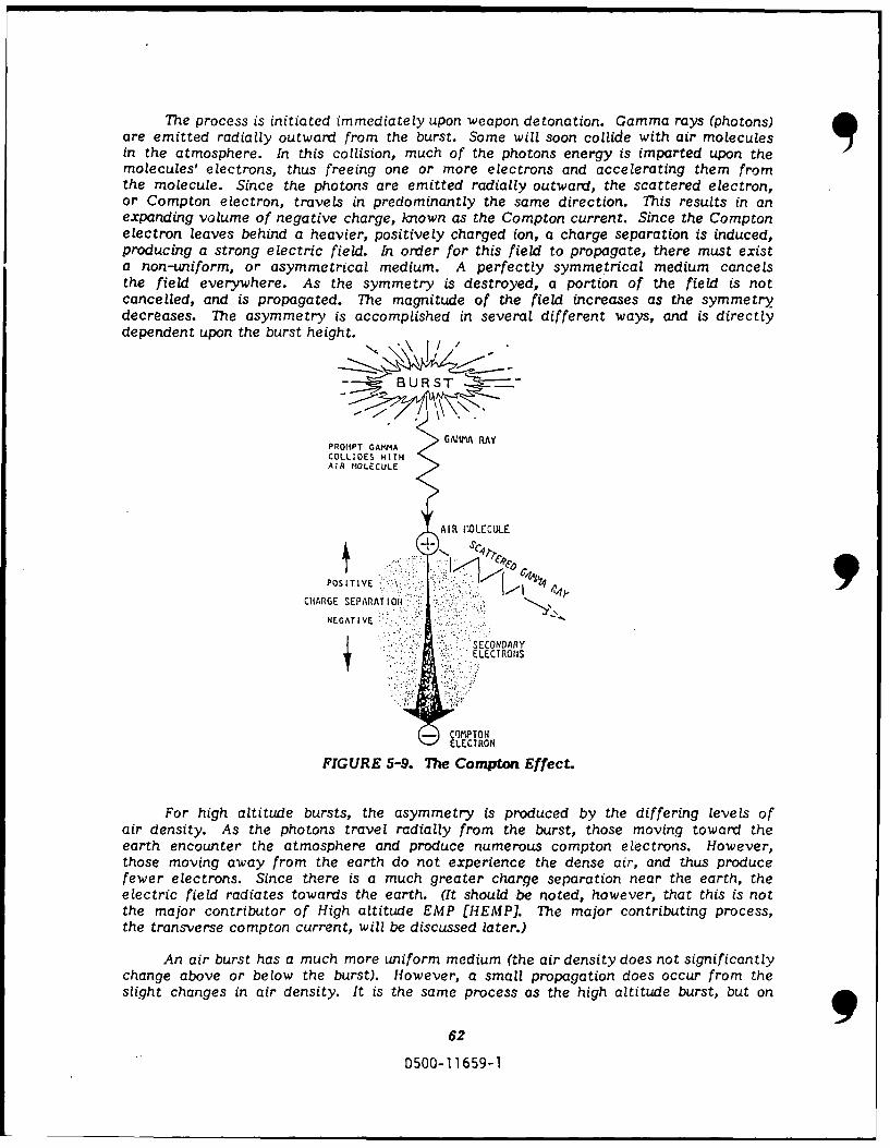
The process is initiated immediately upon weapon detonation. Gamma rays (photons)are emitted radially outward from the burst. Some will soon collide with air moleculesin the atmosphere. In this collision, much of the photons energy is imparted upon themolecules' electrons, thus freeing one or more electrons and accelerating them fromthe molecule. Since the photons are emitted radially outward, the scattered electron,or Compton electron, travels in predominantly the same direction. This results in anexpanding volume of negative charge, known as the Compton current. Since the Comptonelectron leaves behind a heavier, positively charged ion, a charge separation is induced,producing a strong electric field. In order for this field to propagate, there must exista non-uniform, or asymmetrical medium. A perfectly symmetrical medium cancelsthe field everywhere. As the symmetry is destroyed, a portion of the field is notcancelled, and is propagated. The magnitude of the field increases as the symmetrydecreases. The asymmetry is accomplished in several different ways, and is directlydependent upon the burst height.
- BUR
PROMPT GAMMA GAiA RAY
COLLIOS WITHAIR tIOLECULE
AIR ,",OLECULE
POSITIVE 2-fl')eCHARGE SEPARATI lON. 9
NEGATIVE
SECONDARY
ELECTRONS
- COMPTONELECTRON
FIGURE 5-9. The Compton Effect.
For high altitude bursts, the asymmetry is produced by the differing levels ofair density. As the photons travel radially from the burst, those moving toward theearth encounter the atmosphere and produce numerous compton electrons. However,those moving away from the earth do not experience the dense air, and thus producefewer electrons. Since there is a much greater charge separation near the earth, theelectric field radiates towards the earth. (It should be noted, however, that this is notthe major contributor of High altitude EMP [HEMP]. The major contributing process,the transverse compton current, will be discussed later.)
An air burst has a much more uniform medium (the air density does not significantlychange above or below the burst). However, a small propagation does occur from theslight changes in air density. It is the same process as the high altitude burst, but on
62
0500-11659-1
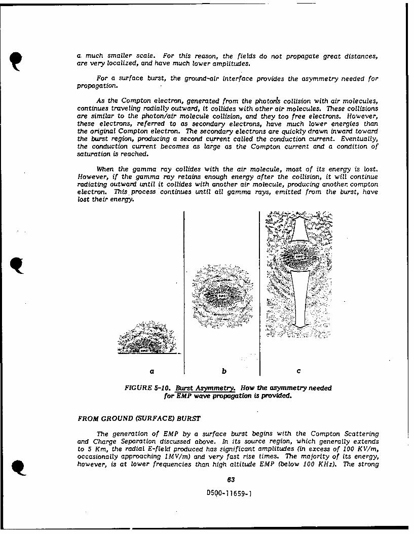
a much smaller scale. For this reason, the fields do not propagate great distances,are very localized, and have much lower amplitudes.
For a surface burst, the ground-air interface provides the asymmetry needed forpropagation.
As the Compton electron, generated from the photons collision with air molecules,continues traveling radially outward, it collides with other air molecules. These collisionsare similar to the photon/air molecule collision, and they too free electrons. However,these electrons, referred to as secondary electrons, have much lower energies thanthe original Compton electron. The secondary electrons are quickly drawn inward towardthe burst region, producing a second current called the conduction current. Eventually,the conduction current becomes as large as the Compton current and a condition ofsaturation is reached.
When the gamma ray collides with the air molecule, most of its energy is lost.However, if the gamma ray retains enough energy after the collision, it will continueradiating outward until it collides with another air molecule, producing another comptonelectron. This. process continues until all gamma rays, emitted from the burst, havelost their energy.
-A4. ' .. >.
5
b- -
. . . . . .. .-. " . .. '.................... .......,
',-..,'. '.: . ;. :: - .' :.-
• :-.., .'* - - •...'
FIGURE 5-10. Burst Asymmetry. How the asymmetry neededfor EMP wave propagation is provided.
FROM GROUND (SURFACE) BURST
The generation of EMP by a surface burst begins with the Compton Scatteringand Charge Separation discussed above. In its source region, which generally extendsto 5 Km, the radial E-field produced has significant amplitudes (in excess of 100 KV/m,occasionally approaching IMV/m) and very fast rise times. The majority of its energy,however, is at lower frequencies than high altitude EMP (below 100 KHz). The strong
63
D500-11659-1

radial field causes the conduction currents to flow in the ground (since the ground ismuch more highly conducting than the air at early times), in opposite directions to theCompton current in the air. These resultant current loops (the Compton current travelingoutward and the conduction current traveling inward) produce azimuthal magnetic fieldswhich are strongest at the earth's surface, and diffuse both upward and downward fromthe ground-air interface. A vertical E-field is also generated and propagated (in theradiating region, which may be extended beyond 10 Km) because of this interface.By not allowing the Compton electrons to travel downward, there is a net positive chargeon the ground and a net negative charge in the air. This separation creates what behaveslike a net vertical dipole, which in turn radiates a vertical electrical field. Thus, fora surface burst, there are radial and vertical electric fields and an azimuthal magneticfield.
There are other components in the EMP produced, due to surface irregularitiesand varying ground properties, that complicate its analysis. The soil and air conductivity,for example, will greatly vary depending on whether the burst occurs in the dry Arizonadesert or the humid coastal regions. The analysis is further complicated by the EMPintroduced within or near a system, by the impinging gamma rays from the nearby burst.This is kn-,,)-n as system generated EMP, and will be discussed later in more detail.Surface burst EMP has very large electric and magnetic field intensities, but is verylocalized. Because of this smaller area of coverage, it presents less of a threat thanhigh altitude EMP. However, since surface burst EMP radiates a vertical electric field,and has a very large portion of it in the lower frequencies, the system impact maysupersede that of HEMP for some systems (even though HEMP field magnitudes aregenerally larger).
CHARGE SEPARATIONPRODUCES RADIALELECTRIC FIELDS
COkPC~t ELECTRONS
/' _;WEAPONr ER N fl> :{:': r
\ I E, I.
f . - -. . : . : . : . .
GROUND
CURRENT LOOPS CURRENTSPRODUCE AZIMUTHLLMAGNETIC FIELOS
FIGURE 5-11. Charge separation.
FROM AN AIR BURST
The generation of EMP by an air burst also begins with the Cornpton Scattering9
64
D500-11659-1

and Charge separation processes (see Figure 5-12). The radial electric field behavesmuch like that of a surface burst, except in an air burst, there is no return path throughground for the conduction current. Thus, no current loops are formed, and the largeazimuthal magnetic fields, characteristic of the surface burst, are not generated. Theasymmetry needed to propagate the radial electric field is provided by the atmosphericdensity gradient. Different densities permit the Compton electrons to travel furtherupward than downward. The asymmetry is reinforced by the typical decrease in watervapor density with increasing altitude. However, even with these two effects combined,the asymmetry produced is much weaker than that of a surface burst, and typical fieldstrengths are much smaller (approximately 300 V/m at 5 Kin)., Since there is a slightasymmetry, there is a small vertical electric field which, in turn produces a small, veryweak azimuthal magnetic field. These fields share characteristics of both surface burstEMP and HEMP, but are much less significant. Any system hardened to withstand HEMPcan also withstand Air Burst EMP. Therefore, we will now turn our attention to HighAltitude EMP.
ppf{ .
FIGURE 5-12. Air Burst EMP.
FROM HIGH ALTITUDE BURST
The generation of EMP by a high altitude burst begins as the surface burst andair burst with Compton Scattering and Charge Separation. Thb asymmetry requiredfor field propagation is produced by the space-atmosphere interface. However, theelectric field due to the charge separation is not the major contributor of HEMP. Themajor contribution is a result of a new phenomenon called Transverse Compton Current.
65D500-11659-1
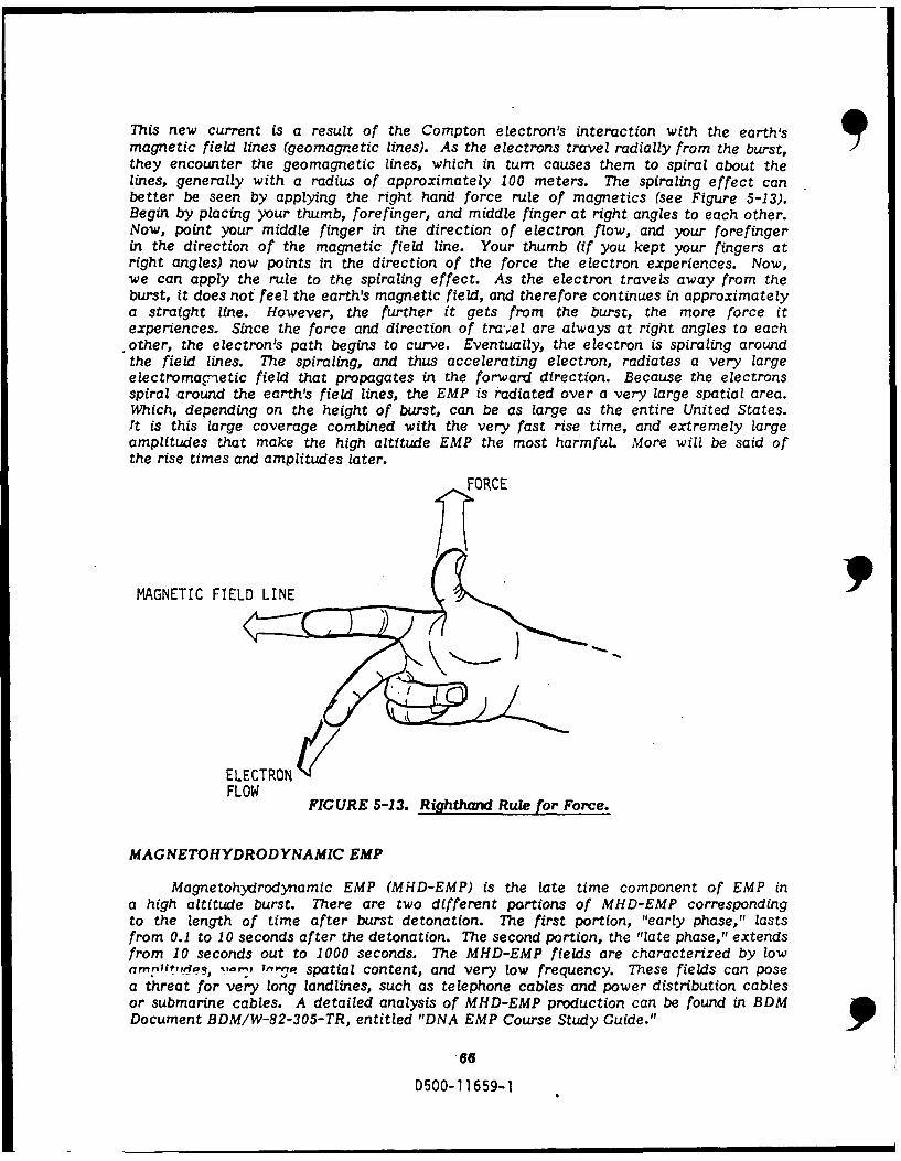
This new current is a result of the Compton electron's interaction with the earth'smagnetic field lines (geomagnetic lines). As the electrons travel radially from the burst,they encounter the geomagnetic lines, which in turn causes them to spiral about thelines, generally with a radius of approximately 100 meters. The spiraling effect canbetter be seen by applying the right hand force rule of magnetics (see Figure 5-13).Begin by placing your thumb, forefinger, and middle finger at right angles to each other.Now, point your middle finger in the direction of electron flow, and your forefingerin the direction of the magnetic field line. Your thumb (if you kept your fingers atright angles) now points in the direction of the force the electron experiences. Now,we can apply the rule to the spiraling effect. As the electron travels away from theburst, it does not feel the earth's magnetic field, and therefore continues in approximatelya straight line. However, the further it gets from the burst, the more force itexperiences. Since the force and direction of tra-'el are always at right angles to eachother, the electron's path begins to curve. Eventually, the electron is spiraling aroundthe field lines. The spiraling, and thus accelerating electron, radiates a very largeelectromagnetic field that propagates in the forward direction. Because the electronsspiral around the earth's field lines, the EMP is radiated over a very large spatial area.Which, depending on the height of burst, can be as large as the entire United States.it is this large coverage combined with the very fast rise time, and extremely largeamplitudes that make the high altitude EMP the most harmful. More will be said ofthe rise times and amplitudes later.
FORCE
MAGNETIC FIELD LINE
ELECTRONFLOW
FIGURE 5-13. RighhaVad Rule for Force.
MAGNETOHYDRODYNAMIC EMP
Magnetohydrodynamic EMP (MHD-EMP) is the late time component of EMP ina high altitude burst. There are two different portions of MHD-EMP correspondingto the length of time after burst detonation. The first portion, "early phase," lastsfrom 0.1 to 10 seconds after the detonation. The second portion, the "late phase," extendsfrom 10 seconds out to 1000 seconds. The MHD-EMP fields are characterized by lowamplPitPfes, -, 7-on, ' spatial content, and very low frequency. These fields can posea threat for very long landlines, such as telephone cables and power distribution cablesor submarine cables. A detailed analysis of MHD-EMP production can be found in BDMDocument BDM/W-82-305-TR, entitled "DNA EMP Course Study Guide."
-66D500-11659-1

AIRSECONDARY MOLECULESSELECTRONS SECONJDARY
ELECTRONS
COMPTON COMPTONELECTRONS ELECTRONS
GEOMAGNET IC FIELD
EARTH
FIGURE 5-14. Transverse Compton. Currents.
SYSTEM GENERATED EMP
The EMP that has been addressed thus far arises from the interaction of gammarays with the atmosphere. There is, however, another type of EMP that arises fromthe interaction of the explosion's gamma rays and x-rays with the system. This "SystemGenerated EMP" (SGEMP) begins when the rays come in contact with the systems outersurface. Whether this is the actual solid material of the electronic system or the shieldingdesigned to protect the system, their atoms are heavier than those present in the air.Consequently, interaction with the rays produce electrons by the Cornpton andphotoelectric effects. The Compton effect has been discussed in detail: The photoelectriceffect is the phenomenon associated with the excitation of electrons and their removalfrom a metal after being exposed to light of sufficiently short wavelengths. In turn,these electrons produce secondary electrons by ionizing more of the metals atoms. Someelectrons produced, whether directly or indirectly, will have a velocity componentperpendicular to the surface and will be emitted from the system. As a result, an electricfield is generated near the surface. Internal EMP (JEMP) is also generated in the systemfrom electrons emitted from internal walls. Appreciable currents and voltages capableof causing failure or disruption of the system can be developed from SGEMP or IEMPjust as it could with the other types of EMP.
67
0500-11659-1

MISSILE IN FLIGHT
S * PRIMARY ELECTRON
e SECONDARY ELECTRON
FIGURE 5-15. System Generated EMP.
ANALYSIS METHODS
GROUND COVERAGE FOR HEMP
EMP from transverse Compton current can travel great distances around the earth.
However, the most harmful effects cover the line of sight region from the burst to the
earth. (See Figure 5-16).
Assuming the earth to be a sphere, the edge of this region is a circle with a radius
of Rt. This is known as the tangent radius because the line of sight from the burst is
at a tangent to the earth. If the height of burst is known, the tangent radius can easily
be determined from equation 5-1. Graph 5-2a shows the tangent radius as a function
of the height of burst.
R t = Re Cos- ' (Re/(Re + HOB) (Eqtn 5-1)
Where Rt is the Tangent Radius (in Kin), Re is the Earth's Radius (approximately
6370 Kin) and HOB is the Height of Burst (in Kin).
The surface area of coverage can be found from the following equation:
At= 2wRp' HOB (Eqtn 5-2)
Re + HOB
Where: At is the Surface Area (in KM'), Re is the Radius of Earth (approximately
6370 Kin), is 3.1415, and HOB is the Height of Burst (in Kin).
68
D500-11659-1
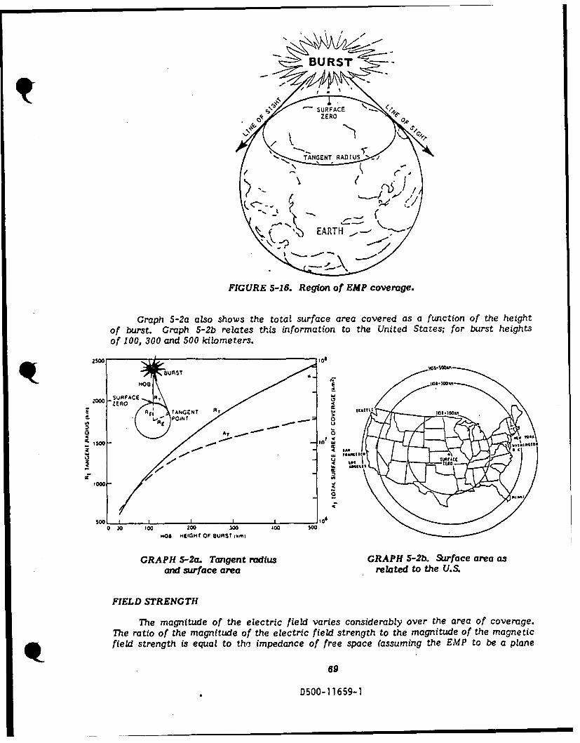
FIGURE 5-16. Region fEPcoeg.
2000 SRFACE N~ SURFNTCE
0< ZEO C!0
of 1030 an 500 kilometer00
SUR0AC A EGTO SATI
FIELD STRNGETM C ~nThe mantd>fteeeti l aiscosdrbyoe h rao oeae
TheraioOTmantdofteeetifilsteghtthmantdofheantcfildstenthiseqaltotMimednc o re sac (ssmig heEM t b apln
A69
ism- 65-

wave over the area of coverage). There are many factors which affect the magnitudeof the EMP, including: Height of burst, weapon yield, geometric location of the burst,and point of observation of the burst. However, the electric field waveform can closelybe approximated with the following equation:
E(t) = EoK(e'0t-e-Bt)V/m (Eqtn 5-3)
for t > = 0
Where B is the Rise constant of 4.76 X 10⁸ s - 1, a is the Decay rate of 4 X 10⁶
s - 1, K is 1.050 (Constant allowing E(t) to reach Eo), t is Time in seconds, and Eo is thePeak Electric Field
Substituting these values into the equation, and assuming a peak Electric field(Eo ) of 50 KV/m, provides the equation for a high yield, high altitude burst.
E(t) = 5.25 X 10⁴ (exp(-4 X 10⁶ t)-exp(-4.76 X 10⁸ t))(V/m) (Eqtn 5-4)
This equation has a rise time of 5 nanoseconds and a time to half value of 200nanoseconds. Graph 5-3 shows the time waveform of the EMP for equation 5-3 and alsorelates the magnetic field to the electric field. 9
50
120
100
30 - 80
E-FIELD KV/d H-FIELD A/i
6020
40
10 20I20
0
1040 10 6
TIME (S)
GRAPH 5-3. Generalized EMP time waveform.
FREQUENCY RESPONSE
A great deal of EMP collectors are frequency selective. Therefore, it is very
70
D500-11659-1

important to determine the distribution of EMP energy in the frequency domain. Thisis easily accomplished by obtaining the Fourier transform of equation 5-3. This yieldsthe following equation:
E(w) 2.47 X 10¹³ (Eqtn 5-5)
(jw+ 4 X 10⁶) (jw+ 4.76 X 10⁸) V-s-m - 1
Where w is radian frequency.
A bode plot of this equation is shown in Graph 5-4 below. This diagram shows thatthe electric field strength is relatively constant between 10 and 100 kHz, decreases bya factor of 100 between 1 MHz and 100 MHz and then continues to rapidly decrease forfrequencies greater than 100 MHz. Moreover, the majority of the fields energy canbe seen to lie below about 100 MHz.
90
80>- C"J
LELECTRICAL FIELD 1UJO
l = " UMULASPECTRUM"> ~ - La -C
bo--
,.,0NORMALIZED
'CUM ULATIVE/ J (J <
io1 105 106 107 108 101
FREQUENCY (HZ)
GRAPH 5-4. Frequency domain plot of EMP energy.
SMILE DIAGRAMS
The smile diagram is a convenient method of determining relative field strengths.The accompanying Figure 5-17 is an example of a smile diagiam for high altitude bursts,ranging in heights from 100 to 500 Km. The results in this figure apply for a groundzero location between approximately 300 and 600 North latitude; or approximately overthe continental United States. The reason ground zero must be specified, is that theCompton electrons must intersect the geomagnetic field lines in order to produce anyEMP. Thus, the Compton electrons parallel to the field lines will not produce any EMP.The null area directly north of ground zero is because of this parallel effect. The typicaldip angle of the geomagnetic field over the United States is approximately 670.
0 i
D500-11659
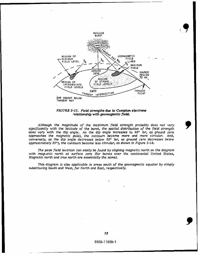
NUCLEARBURST
-... *, IiRS\ p'±,."
REGION OF ' " GEOMAGNETIC
-MI N IMUM , BO 4"K P B FIELD "•FIELD LEVEL 10 ... DvO "lO LINES
EMP ABSENT BELOWTANGENT RAY
FIGURE 5-17. Field strengths due to Compton electronsrelationzship with geomagnetic field.
Although the magnitude of the maximum field strength probably does not vary 9significantly with the latitude of the burst, the spatial distribution of the field strengthdoes vary with the dip angle. As the dip angle increases to 900 (or, as ground zeroapproaches the magnetic pole), the contours become more and more circular. And,conversely, as the dip angle decreases below 500 (or, as ground zero decreases belowapproximately 300), the contours become less circular, as shown in Figure 5-18.
The peak field location can easily be found by aligning magnetic north on the diagramwith magetic north at swrface zero (for bursts over the continental United States,Magnetic north and true north are essentially the same).
This diagram is also applicable in areas south of the geomagnetic equator by simplysubstituting South and West, for North and East, respectively.
72
D7500-1 1659-1
• ,, I 30 Im

MAX . t MAX
GROUND DI STANCETO TANGENT POINT MAGNETIC GROUND DISTANCE
NORTH TO TANGENT POINT
x .foo . GROUND
0, \5 MAX ZERO,, I 1nos MAGNETIC
2 x 1106
EMAX
4 x lOB
GROUND DISTANCETO TANGENT POINT
0.S MAX
FIGURE 5-18. Smile dagram shoving relative
electric field strengths.
73
D500-11659-1

COUPLING THEORY
An electric field is measured in volts per meter (v/m). A potential of one volt,separated by one meter, produces an E field of 1 v/r. If the electric field vector isin the plane of incidence, then the field is said to be vertically polarized. If it is perpen-dicular to the plane of incidence, then iL is horizontally polarized.
HORIZONTAL POLARIZED WAVE VERTICAL POLARIZED WA E
E X X
-H
FIGURE 5-19. Horizontal and vertical polarized waves.
A conducting media, such as a piece of wire, exposed to this field will have avoltage induced on it and a current flowing in it. The amount of the current is dependenton the voltage that is induced on it and the resistance of the wire. The voltage inducedis dependent on the electric field and the angle that the field makes with the wire.This field will induce a voltage and a current on any conducting media it encounters,such as an airplane skin, an antenna, power lines, etc. The induced current will producea secondary electromagnetic field, but this field is small compared to the EMP andcan, in most instan es, be ignored. There are a few exceptions that will be pointedout later.
There are two types of coupling devices: intentional (antennas), and nonintentional(power lines, telephone lines, etc.). Coupling through an antenna is a straightforwardexercise in antenna theory, and will not be covered. A very good distinction of howEMP couples to antenna's can be found in the "DNA EMI- Handbook," (DNA-3466F).
EMP can be coupled into a protected area by anything penetrating the area, suchas: power or telephone lines, or cabling (both electrical and mechanical). Also, coblingthat is totally inside the protected area but passes next to a door, or a non-protectedpenetration, i.e. a control cable, can pick up a sufficient amount of EMP to cause damage.This is why it is important to decouple all penetrations. For instance, the energy coupledfrom a control cable to a data bus is from the secondary electromagnetic field mentionedearlier.
A mathematical model will be developed to define the voltage induced on overheadpower lines by EMP. From this model, the voltages and currents induced in differenttypes of lines can be estimated. Mathematical models will then be developea for currentscoupled to inner conductors of shielded cables. Next, different types of shielded cables
74
D500-11659-1
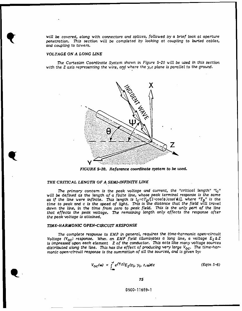
will be covered, along with connectors and splices, followed by a brief look at aperturepenetration. This section will be completed by looking at coupling to buried cables,and coupling to towers.
VOLTAGE ON A LONG LINE
The Cartesian Coordinate System shown in Figure 5-20 will be used in this sectionwith the Z axis representing the wire, and where the yz plane is parallel to the ground.
FIGURE 5-20. Reference coordinate system to be used.
THE CRITICAL LENGTH OF A SEMI-INFINITE LINE
The primary concern is the peak voltage and current, the "critical length" "1 c"will be defined as the length of a finite line, whose peak terminal response is the sameas if the line were infinite. This length is lc=cTp/(1-cos(e)cos(*), where "Tp" is thetime to peak and c is the speed of light. This is the distance that the field will traveldown the line, in the time from zero to peak field. This is the only part of the linethat effects the peak voltage. The remaining length only affects the response afterthe peak voltage is attained.
TIME-HARMONIC OPEN-CIRCUIT RESPONSE
The complete response to EMP in general, requires the time-harmonic open-circuitVoltage (Voc) response. Whey. an EMP field illuminates a long line, a voltage EzAZis impressed upon each element Z of the conductor. This acts like many voltage sourcesdistributed along the line. This has the effect of producing very large Voc. The time-har-monic open-circuit response is the summation of all the sources, and is given by:
Voc(w) = j e ( YZ)Ez(xi, yi, z,uadz (Eqtn 5-6)~-"
75
D500-11659-1

Where Ez is the total longitudinal electric field at the average height of the line.The e(Yz) term is a scaling factor produced by the progression of the primary wave,toward the terminal, and the reflected wave coming from the open terminal. This waveis, in general, composed of both a vertical and a horizontal component, and each com-ponent has an incident and a reflected part. The horizontally polarized part of thewave is given by:
Eih(x,y,z, w = F4(x,yz,w) [Yocos(O) + Zosin(e)]
The z component is therefore:
Eih = Eosin(e)
The z component of the ground-reflected electric-field vector is found by multi-plying Eih
z by the reflection coefficient. For horizontal, it will be:
Erh= Eosin(e)Rhe-2jkhsin(*)
Rh Sin() - C(E + a - cos'(4)isin(M +) + +r(1 + Oq/,j- - cos2( )]
Where k is the wave number, h is the height of the wire, er is the relative permotiv-ity and og is the conductivity of the ground.
Rh is the ground reflection coefficient for horizontal polarization. The totallongitudinal electric field at the conductor for horizontal polarization is the sumof the incident, and reflected component, and is:
h= Eosin(O)+Rhe-j2 khsin(*))e- kzcos(O)cos(o) (Eqtn 5-7)
Where [eIkzcOs(O )cos(*)] accounts for the pho lance down the line, and "k"is the wave number, and is equivalent to one over ,ve length).
Similarly, the total longitudinal electric field at the conductor for vertical polariza-tion is:
EY = Eosin(W)cos(e)[1-Rve-i2khsin($)Je-]7zcos(e)cos(*) (Eqtn 5-8)
Where Rv is the ground reflection coefficient for vertical polarization.
R= r( 1 + og/jujsin(#)-c r(l +ag/j1w)-cos 2 (V1)] (Eqtn 5-9)
r(1+ ag/iwJsin(*)+[ ¢ r( +og/jiwV-cos' ( )]
76
D500-11659-1

IMPULSE RESPONSE
Substituting equations (5-7) and (5-8) into equation (5-6) setting Eo=1 and takinginto account the phase variation gives the common-mode Voc at the terminals for horizon-tal and vertical polarizations, where Y=Y0 H(j w):
vj c = sin(O)[( +Rhe-j2 khsin(0)] (Eqtn 5-10)
Y -jkcos(O)cos(O)
VQ'c = sin(*)cos(O)(1-Rve-j 2 khsin(0)] (Eqtn 5-11)
y -jkcos(O)cos(O)
If the line and ground planes are perfect conductors, the propagation constantY= jk = ]w/c and the reflection coefficients Rh and Rv become -1 and +1, respectively.Equations (5-10) and (5-11) then become:
Voh = cDh(O,*)(1-e-J' Tc)lj /
Vov = cDv(O,*)(-e WTc)/j W
Where Tc is the time delay between incident and reflected planes of equal phase,qalso called- the clear time, and Dh, Dv are the directivity functions.
Tc = 2hsin(*)/c
Dh(O,*) = sin(O)/[1 -cos(O)cos(*)]
Dv( ,4 = sin(T)cos(O)/(l-cos()cos(m)J
The inverse Fourier transformations of V9c and Vvc yield the system impulseresponse:
ch(O), 0) 0 <_ t<Tc
ho (Eqtn 5-12)
0 t>Tc
and
cDv(O, ) 0 < t<Tc
h~c (Eqtn 5-13)
0 t>Tc
77
0500-11659-1

To find the power-line Voc response to EMP, you must convolve the system response,equation (5-12) or (5-13), with the EMP time dependent waveform.
This convolution produces:
(1/8) (e-St-1)-(1/a) (e-at-1) OSt < Tc (Eqtn 5-14a)
Vo4(t) = cDh(O,A) Eo
(1/,) e-Bt(1-e8Tc)-(1/az)e-at(1-e Q'Tc) t > Tc (Eqtn 5-14b)
(1/8) e-t-1)-(1/)(e-t-1) OSt < TC (Eqtn 5-14c)
Voc(t) = cDvZQ,*)Eo
(1/B )e-St(1-eB Tc)-(1/a)e-at(1-e T C) t > Tc (Eqtn 5-14d)
Where a and 8 are the time constants for the EMP, and Tc is the clear time.
These equations show that the Voc for a lossless line depends on the directionof incidence, the time for the reflected wave front to reach the conductors, and theparameters of the EMP time waveform. The response before Tc is due only to the directincident wave front. The response after Tc is the result of the combination of two wave-fronts, one traveling in the positive direction, and one traveling in the negative direction.The combination of these two waves has a limiting effect on the maximum Voc.
EXAMPLE 5-1:
GIVEN: A cable that is 5-cm in diameter, and ft 0.5 meters above a metalground plane, i3 illuminated by a 15kv/m EMP wave. The anglesof incidence, e and * are 00 and 300, respectively. Find the peakVoc at )-= 0.83X10⁻⁹ec.
FIND: Using equation 5-14d, the first value to find is Tc, the clear
time.
SOLUTION: Tc = 2(0.5)sin(30o)/3x10 8 = 1.667z1O- 9
Next, find the directivity function value:
Dv(0,300) = [in(30)cos(O0)]Ki-cos(O0)cos(30°)J = 3.732
The Vvoc can now be found by:
Voc = (15x103 )(3z10 8 )(3.732)
e-476 X 06(10.83X O"9 ) (1-e 4 7 6 X 1 0 6 (1 . 6 6 7 X I 0- 9 )
476 X 106
e- 4 X 10⁶(10.83 X 10--9)(1e 4 X 10⁶(1.667 X 10⁹))] 78
4 X 10 6
D500-1 1659-1

= 16.79 X 10¹² [12.12 X 10⁻¹² (-1.211)] - [239.4 X 10⁻⁹(-6.69 X 10⁻³)]= 16.79 X 10¹² [-14.68 X 10⁻¹²) - [-1.602 X 10⁻⁹.= 16.79 X 10¹² [1.59 X 10⁻⁹] = 26.70 Ic
To generalize, for a line that has an average height of 0 meters, a * of 900,(directly overhead), the Voc for a horizontal polarized wavefront, peaks at about 900kvolts in 70 nanoseconds. At grazing, (*=0) the peak is about I megavolt in about 10nanoseconds. For a vertical polarized wavefront, the peak can be as much as 2 megavolts.
It can be shown that the horizontal directivity function is greatest with respectto 0 when 0 = @ for a fixed elevation angle.
Dh (0,@) = 1/sin (41) (Eqtn 5-15)e=*
The combination of equations (5-14b) and (5-15) gives an expression for the maxi-mum voj as a function of *.
Voh I = [cEolsin(4i)][(1/ 8)e- tp(1-e B3Tc)-(/a)e-atp(1-e a T c )]
Peak
Where tp is the time to peak.
tp = [1/(O-a)]ln[(1 -e aTc)]
The theoretical maximum peak Voc occurs at grazing, O(=0, and is 2hE o.
The peak Voc for vertical polarization for a given angle * is maximized with respectto a, when 0 = 0. As with horizontal polarization, the peak of the Voc increases, andthe time to peak decreases as the elevation angle approaches grazing.
The peak Voc for vertical polarization is:
VYcEo sin(* ((1 aet24.. Tcr(/j) (~ ))oc Peak E )-(l/)e- p(i c)(l-cos(*)J/
The Voc for vertical ranges from about 900kv at normal incidence, to a maximumof 2 megavolts at grazing. The time to peak also increases from about 70 nanosecondsfor 0=30, to 10 nanoseconds for 40=0. The maximum Voc for vertical is given as:
,,v = 4hEo
This is twice as large as the peak voltage for horizontal.
79
D500-11659-1

SEMI-INFINITE LOSSY LINE
Up to this point, all the materials have been perfect: perfect conductors and perfectinsulators. In the "real world" there is no such thing as a perfect conductor or insulator.Therefore, if a "real world" voltage is to be found, "real world" material must be con-sidered. This means that the assumption that T =1 can no longer be made.
Substitution of the "real world" lossy line propagation constant (Y= Y H(jw)) intoequations (5-10) and (5-11), yields the Voc transfer function for a lossy line:
Voh (j)=c sin (e)[(1 +Rhe - j WTc)] / jw[H (jM)-cos(O)cos(*))
Vvc(jw)=c sin()cos(O)(-RveJ(4Tc)] / jW[H(jw)-cos(O)cos(*)J
Noting that the Fourier transform of the EMP waveform is:
F(w) = (O )W +
The complete "real world" response can now be found. To get the time domainresponse, the inverse Fourier transform must be found. This is no easy matter. Equation5-16 and 5-17 show the integral that must be solved.
Voh(t) = 1_fVoc(jw) E(w)ejt.,tdw (Eqtn 5-16)2w-r
VoVc(t) = _1 Vc(j ) E(w)ejWtdw (Eqtn 5-17)
Numerical techniques must be used to evaluate the integrals in equation (5-16)and (5-17). A fast fourier inversion routine was used to obtain results for worst-caseangles of incidence over a range of typical earth conductivities, (10- 3 to 10-1 mhosper meter) and a nominal line height of 10 meters for which the results follow:
The maximum peak Voc for vertically polarized waves increases from about 2Mvto more than 7Mv. This change is caused by the fact that the reflection coefficientis not unity, and thus the reflected wave does not completely cancel the incident wave.The horizontal reflection coefficient does not change very much in magnitude or phase,and therefore, the cancellation of the incident wave is more like the ideal case. Table5-1 gives peak Voc, peak short circuit currents, time to peak, critical length of lineand angle of incidence for maxima for both polarizations for a typical power line tometers high with Zc = 500 ohms.
p80
D500-11659-1
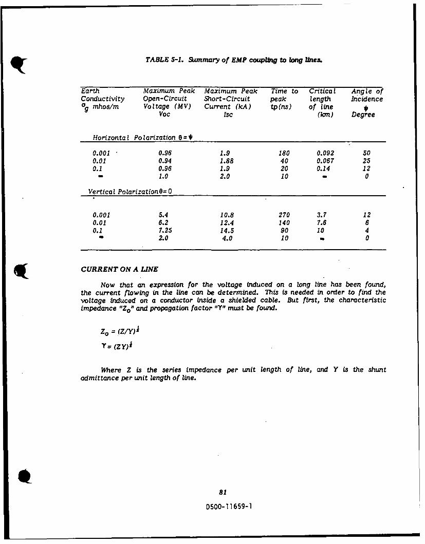
TABLE 5-1. Sunmary of EMP coupiIng to long lnes.
Earth Maximum Peak Maximum Peak Time to Critical Angle ofConductivity Open-Circuit Short-Circuit peak length Incidence
m nhos/m Voltage (MV) Current (kA) tp(ns) of lineVoc Isc (Ian) Degree
Horizontal Polarization 0=
0.001 0.96 1.9 180 0.092 500.01 0.94 1.88 40 0.067 250.1 0.96 1.9 20 0.14 12
- 1.0 2.0 10 - 0
Vertical Polarization 6=0
0.001 5.4 10.8 270 3.7 120.01 6.2 12.4 140 7.6 60.1 7.25 14.5 90 10 4
2.0 4.0 10 0
CURRENT ON A LINE
Now that an expression for the voltage induced on a long line has been found,the current flowing in the line can be determined. This is needed in order to find thevoltage induced on a conductor inside a shielded cable. But first, the characteristicimpedance "ZO" and propagation factor "'" must be found.
Z = (Z/Y)
Y= (ZY)i
Where Z is the series impedance per unit length of line, and Y is the shuntadmittance per unit length of line.
81
D500-11659-1
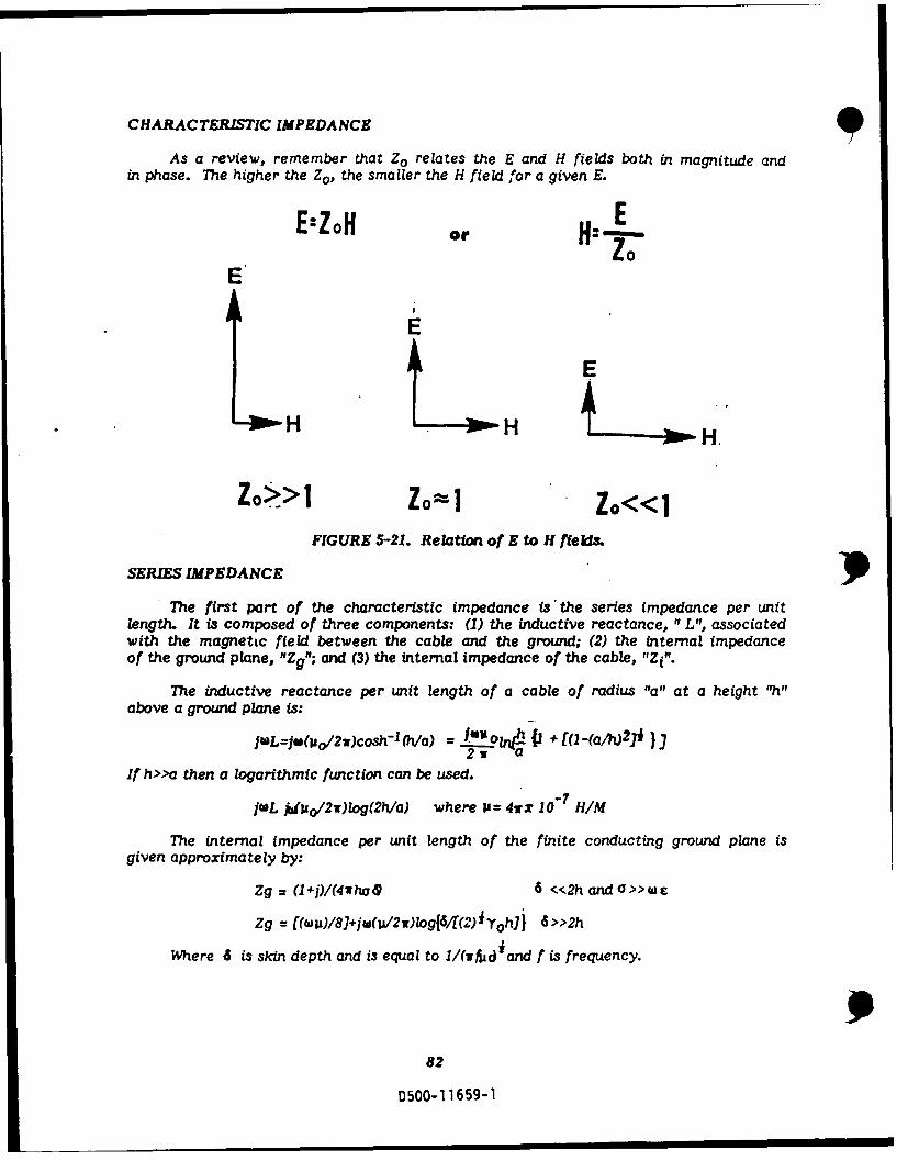
CHARACTERISTIC IMPEDANCE
As a review, remember that Zo relates the E and H fields both in magnitude andin phase. The higher the Z., the smaller the H field for a given E.
E:ZoH oEE'
EE
E E
H A HL H
Zo>> Zo=l Zo<<
FIGURE 5-21. Relation of E to H flekis
SERIES IMPEDANCE
The first part of the characteristic impedance is the series impedance per unitlength. It is composed of three components: (1) the inductive reactance, "L", associatedwith the magnettc field between the cable and the ground; (2) the internal impedanceof the ground plane, "Zg"; and (3) the internal impedance of the cable, "Zi".
The inductive reactance per unit length of a cable of radius "a" at a height "h"above a ground plane is:
jwL=jw(&o/2w)cosh-l (h/a) = I'. Ol4! F + [(1 -(alh)2J* }2~ a
If h>>a then a logarithmic function can be used.
JUL j~mo/2)log(2h/a) where i= 41rx 10- 7 HIM
The internal impedance per unit length of the finite conducting ground plane isgiven approximately by:
Zg = (1+j)/(4wha4 6 <<2handO>>wc
Zg = ((w u)/8)+jw(U/2w)log{6/[(2) iYoh]j 6>>2h
Where 6 is skin depth and is equal to 1/(lfd i and f is frequency.
982
D500-11659-1
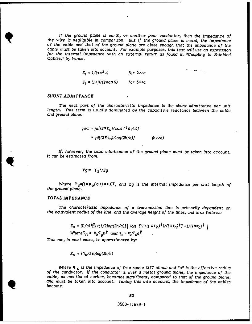
If the ground plane is earth, or another poor conductor, then the impedance ofthe wire is negligible in comparison. But if the ground plane is metal, the impedanceof the cable and that of the ground plane are close enough that the impedance of thecable must be taken into account. For example purposes, this text will use an expressionfor the internal impedance with an external return as found in "Coupling to ShieldedCables," by Vance.
Zi = i/(wa2 o) for S>>a
Zi = (1+)/(2vaod) for 6<<a
SHUNT ADMITTANCE
The next part of the characteristic impedance is the shunt admittance per unitlength. This term is usually dominated by the capacitive reactance between the cableand ground plane.
jw C =w[(2 I Eo)/cosh- 1 (?/a)]
jwf(2 Teo/log(2h/a)]
If, however, the total admittance of the ground plane must be taken into account,
it can be estimated from:
Yg = Y s 1/Zg
Where TS=[j'o(a+jWE)], and Zg is the internal impedance per unit length ofthe ground plane.
TOTAL IMPEDANCE
The characteristic impedance of a transmission line is primarily dependent onthe equivalent radius of the line, and the average height of the lines, and is as follows:
Zo = (L/c)iff u-f1/2log(2h/a)]J lqg [(1+(j WTh)i)/(jWTh)i ] +1/(j 4ta)i
WhereTh = ha and ?. - oca.
This can, in most cases, be approximated by:
Zo =(rno/2w)Iog(2h/a)
Where n o is the impedance of free space (377 ohms) and "a" is the effective radiusof the conductor. If the conductor is over a metal ground plane, the impedance of thecable, as mentioned earlier, becomes significant, compared to that of the ground plane,and must be taken into account. Taking this into account, the impedance of the cablesbecome:
83
D500-11659-1

Zo = 60coshI1 (h/a) or Zo= 60 log (2 h/a) for (h>>a)
PROPAGATION CONSTANT
The propagation constant "'1I" relates how the wave behaves as it travels downthe cable. It is, in general, a complex number, composed of a real part "a",, and animaginary part "8 ". The real part is the attenuation. corl.tant, and the imaginary partis the phase constant.
Y= rA+]j
Where 8 is the phase. constant given by:
1= Im(ZY)i where Im means the imaginary part of (ZY)
and
c= 1/(2Zo)[1/2va (if- C) i + (1/4 h (.L.) i)]a
Where Uc is the permeability of the cable shield, c is the conductivity of thecable shield, 1A is the permeability of the ground plane, a is the conductivity of theground plane, and f is frequency. p
The value of the attenuation constant, given above, is applicable to high frequenciessuch that:
2f>1/(TicOcTc )
and
f)1/(VO/Tg )
Where Tc and Tg are the wall thickness of the cable shield and the ground plane,respectively.
The attenuation constant a and the phase factor B are needed for the directivityfunction. The equations given earlier were good approximations when 0 =k, and whenM/k is negligible. Where I" is the wave number and is equal to W/c, these assumptionsare safe for good conducting ground planes such as metal or aerial transmission lineswhen the angles of incidence are large. If the ground plane is not a good conductor,as in composite skinned aircraft, for cos(e) cos(#)-1, you must take the propagationconstant into account. The complete directivity functions are given by:
Dh(e,@*) = sin(e)/((c/jw) + (8/k)-cos(*)cos(e)]
Dv(o,*) = sin(*)cos(e)/[(cc/jw) + (0/k)-cos (*)cos(8)]
84
0500-11659-1

If we use the +:bove equations, we can find a more exact approximation of thevoltage induced on a long line. If we divide this voltage by the characteristic impedance,we will get the current flowing through the cable which may be the outer shield of ashielded cable and can be expressed as the following equation:
0Isc(w) = (1/Zo) f e("fZ)Ez(z,w)dz
COUPLING TO SHIELDED CABLES
One way that EMP can be coupled to the inner conductor of a shielded cable,is by the field produced by the current which flows in the shield. Another, is by holesin the shield; i.e., braided shields. The first can be modeled as a voltage source thatis equal to the current flowing in the shield, times a transfer impedance(Zt). The second,is a current source that is equal to the voltage between the internal conductor, andthe external structure, times a transfer admittance. This voltage is very close to thevoltage of the shield, because the voltage between the shield, and the inner conductoris small, compared to Vo. If IoZt>>VoYtZi,2 , the transfer admittance term can beneglected. Z 1 ,2 stands for the load impedance at either end of the line. Both ends mustmeet this requirement.
ZT 1 0 dz Z dz [ +aldz
az
V + LV daz
V Ydz -V oy. dz
Ji~ dz-
FIGURE 5-22. Equivalent circuit for the internal circuitwhen both the transfer impedance and the
transfer admittance are included.
TYPES OF SHIELDS
The following types of shields will be discussed: Solid thin walled tube, braidedwire and tape-wound or spiral shields. The use of ferromagnetic shields will then bediscussed briefly.
The general form of the transfer impedance is given by:
Zt 1 dV
10 dz 1=0
85
0500-1 1659-1

Where Io is the total current flowing in the cable, I is the current flowing in theconductor, and dV/dz is the voltage per unit length generated by this current flowingalong the transmission line formed by the shield, and the conductors inside the shield.The transfer impedance gives the Voc developed between the internal conductors, andthe shield for one ampere of shield current in a cable, one meter long (at wavelengthsmuch greater than one meter).
SOLID TUBULAR CABLE
In a solid, thin walled, tubular shield, the only way EMP can be coupled to theinner conductor, is by diffusion of the electromagnetic fields :hrough the walls of thetube. Thus the current source can be neglected. The transfer impedance of a thin walledtubular shield is given as:
Zt = [1/(2ia aT)l [(1 +I)T/61/ sinh[(l +j)(T/6)J
Where "a" is the rddius of the shield, "T" is the thickness of the wall of the shield,is the conductivity of the shield, and 6 is the skin depth in the shield, given by:
6 = (WfI' a)-
It is assumed that the wall thickness T is small, compared to the radius "a" ofthe tube. At low frequencies, such that T/6<<I, the magnitude of the transfer impedanceis:
IZtF1/1(2wa aT) =R 0, (T/6<<1)
Where Ro is the dc resistance of the tube per unit length. Some values of Ro
for typical shielding materials can be obtained from Graph 5-5.
8690500-11659-1
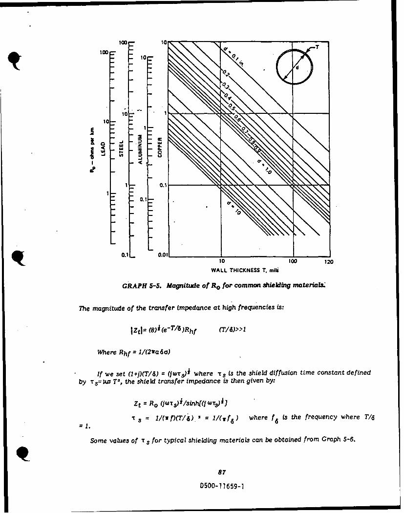
1000
10
10-
IA - i 0
1C -b
4.0.1 _ _
WALL THICKNESS T. mili
GRAPH 5-5. Magnitude of R0 for common sh~ielding materiaL&
The magnitudie of the transfer impedance at high frequencies is:
Where Rhf = 1/(2wa6a)
If we set (1+1)(T/6S) = (jWT5 )' where TS is the shield diffusion time constant definedby Tr s= ka T2, the shieldc transfer impedance is then given by:
Zt R.~ (jWT5)1/sinh(j WT&)iJ
1 = 1/Cu M)T/ 6) 2 = 1/(wf 6 ) where f6 is the frequency where T16
Some values Of T s for typical shielding materials can be obtained from Graph 5-6.
87
D500-1 1659-1

0 a aT $
- -
1.3 x 10 7 J- Z--3.6 X 10 7
GRAPH 5-6. Dif/kiio time for vaiu metaLs.
RESPONSE OF SHORT CABLE
Thie response of an electrically short cable that has a shield dc resistance perunit length Ro, and the total shield current flowing in it is of the form Ioe-t/T , is given
by: V() = f(IoRol)12] (jWT)i /[(JW+j/-)3nh(j Wr)i l
This equation attunes a current peak at the center conductor, which has a matchedload or open at both ends.
"here 1o is the peak current flowing in the shield. This equation gives the voltagedeveloped between the center conductor and the shield.
The length "I", for which the electrically short cable approximation is v([lid, isa function of the diffusion time constant, and the wall thickness. If 1<<cT3/(Erd , thenthe short cable approximation is valid.
For completeness, the current in the center conductor is found by:
l(W)= V(()/Z oWhere Zo is the characteristic impedance of the center conductor for a matched load j
at the far end and at the near end.
88
D500-11659-1
I-I
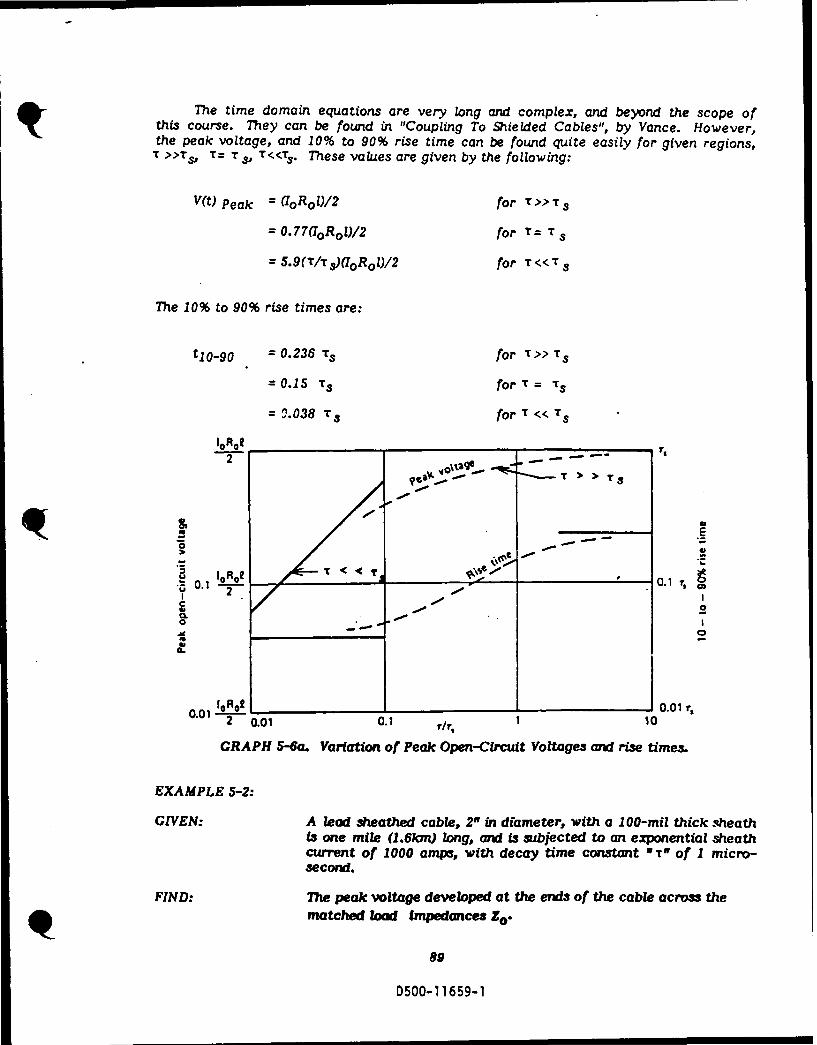
The time domain equations are very long and complex, and beyond the scope ofthis course. They can be found in "Coupling To Shielded Cables", by Vance. However,the peak voltage, and 10% to 90% rise time can be found quite easily for given regions,
T >>TSO T= T Sp T<<TS" These values are given by the following:
V(t) Peak = (IoR0 1)/2 for t >>Ts
= 0.77 0 Rool)/2 for T= T s
= 5.9(T/T5 )aOROl)/2 for T<<T 3
The 10% to 90% rise times are:
t10_90 = 0.236 T s for T >> T s
=0.15 Ts forT= Ts
= 0.038 T for T << Ts
S>
C..,-~ - -
0I
IoR 0 0.01 r,
2 0.01 0.1 1, 10
GRAPH 5-6a. Variation of Peak Open-Circuit Voltages and rise times.
EXAMPLE 5-2:
GIVEN: A lead sheathed cable, 2w in diameter, with a 100-mil thick sheathis one mile (1.6km) long, and is subjected to an exponential sheathcurrent of 1000 amps, with decay time constant R TO of 1 micro-second.
FIND: The peak voltage developed at the ends of the cable across thematched load Impedances Zo .
89
D500-11659-1

SOLUTION: From Graph 5-6, T s = 3.5 x 10⁻⁵ for the lead sheath, mid Tc 7
= 1O.skm, so the 1.6kn segment (3 electrically short for thepenetrating frequencies, and for low dielectric constmt Inumation.The diffusion time constant TS is much larger than T, T/ T =2.86 z 10-2. The peak voltage can be approximated by 5.9(T/ s)(7oR0 /2). From Graph 5-5, Ro is 0.55 ohms/an. Therefore,10 ROV2 = 0.274 z 1000 x 1.6 2 440v. LookAng at Graph 5-6a, theopen circuit voltage is estimated to be Voc 0.1.69(440) = 74volta. The 10% to 90% rise time L0.038T 31.33 X 0-6. ewaveform wou be the form of that Omm in -Figure 5-23a.
Figure 5-23 shows the normalized waveforms of a short cable for the three casesgiven above. tp .Its tp =3.5 X M4
6~~~t .. -. -. _.I .I-I-
- << II-- 4 l r > > r l
3 .,. - -",, "~ I IU . ,' -- . -. ' * . . . . .
a 0.1 0.2 0.3 0.4 0.5 0.6 0.7 0.8 00 0.1 0.2 0.3 0.4 0.! TIME - 1I/t
TIME - tt (Ib) STEP FUNCTION RESPONSE 1Io0 u(11
l IMPULSE RESPONSE IrIo61hl
TIME - trs
iX E PONENTIAL CURVE I"1.0i 2
FIUE52. Nomlzd aeom f r oT "e
BRAIED.WRE SIELD
T t 0.4 i ty
L., I Lj0 0.1 0.2 0.:3 0.4 O.S 0.6 0.7 0.9 0.9 '1.0
TIME - tits
(a EXPON ENTIA L RESPON S E (1o0
FIGURE 5-23. Normalized waveforms for a short cable.
BRAIDED-WIRE SHIELDS
The most common type of shield used, is a braided-wire type. When properly
made, this type of shield is almost, but not quite, as good as the solid tubular type ofshield. The weaving of the braided-wire shield is described in terms of the number pof carriers (bands Cr groups of wires) that makc up the shield, the number of ends (strandsof wire) in each carrier, the number of picks (carrier crossings) per unit length, andthe weave angle or angle between the carrier, and the axis of the shield.
9013nniiA. K£0.1

Vs -Vo(Z) Vo(Z)
FIGURE 5-24. Sample of a typical braided-wire sield.
WEAVE CHARACTERISTICS
The five properties of a braided shield needed to define its characteristics are:(1) the radius "a" of the shield, (2) the number of carriers "C" in the braid, (3) the picks"P?, (4) the ends "N", and (5) the wire diameter "d".
The principal characteristics of interest are:
4v(a +d) PWeave angle: Q= tan-, 4va+ )Eqtn 5-18)
NCFill: F = (PNd)/sin(a) = 4W(a )Eqtn 5-19)
Optical coverage: K = 2F-F2 (Eqtn 5-20)
volume of metal: v = w'adF (Eqtn 5-21)
In the above expressions, and all the following discussions, it is assumed that thestrand diameter "d", and the aperture dimensions are small compared to the shield radius"a" and that the shield radius "a" is small, compared to the shortest wavelength ofinterest.
EXAMPLE 5-3:
GIVEN: The weaving data for a braided wire shield are:
Shield radius: a = 1 cm = 0.01 mStrand Diameter: d = 6.3 mils = 1.6 X 10⁻⁴ metersWeave angle: a = 300Number of carriers: C = 48Strands per carrier: N = 11
FIND: The optical coverage *K," and the Picks "p".
91
D500-11659-1
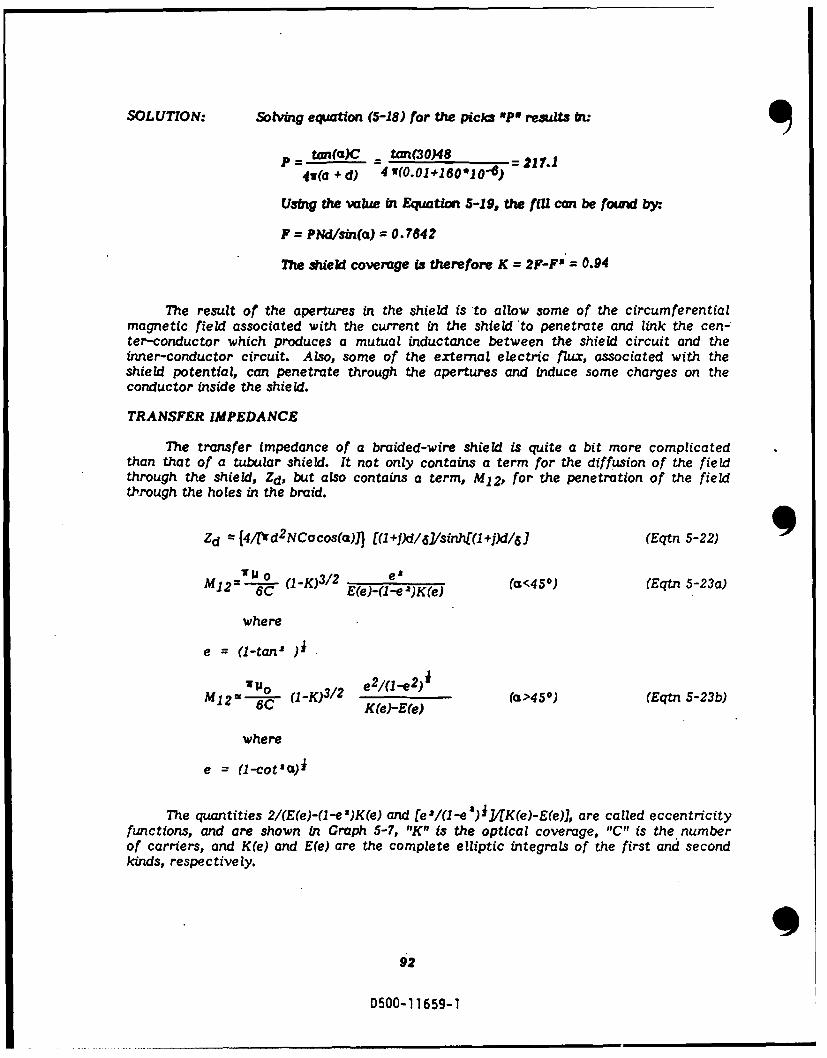
SOLUTION: Solving equation (5-18) for the picks 'Pff results bu
p = tan(c)C = tan(3O)48 = 217.4v(a + d) 4 ir(0.01+160*10-6)
Using the value in Equation 5-19, the fill can be found by:
F = PNd/in(a) = 0.7842
The shield coverage is therefore K = 2F-F2 = 0.94
The result of the apertures in the shield is to allow some of the circumferentialmagnetic field associated with the current in the shield to penetrate and link the cen-ter-conductor which produces a mutual inductance between the shield circuit and theinner-conductor circuit. Also, some of the external electric flux, associated with theshield potential, can penetrate through the apertures and induce some charges on theconductor inside the shield.
TRANSFER IMPEDANCE
The transfer impedance of a braided-wire shield is quite a bit more complicatedthan that of a tubular shield. It not only contains a term for the diffusion of the fieldthrough the shield, Zd, but also contains a term, M12, for the penetration of the fieldthrough the holes in the braid.
Zd ={4/Wd2NCacos(a)1J [(1+])d/61/sinh[(1+J)d/61 (Eqtn 5-22)
E12=m)( -1K 2e (-(<45O) (Eqtn 5-23a)
where
e = (1-tan' ]i
= 1-° e/-ee) (a>450 ) (Eqtn 5-23b)6C I-)/ K[e)-E(e)
where
e = (1-cot'a)i
The quantities 2/(E(e)-(1-e ")K(e) and [e'1(1 -e ') i/(K(e)-E(e), are called eccentricityfunctions, and are shown in Graph 5-7, "K" is the optical coverage, "C" is the numberof carriers, and K(e) and E(e) are the complete elliptic integrals of the first and secondkinds, respectively.
992
D500-11659-1

C2 1 tan ? 1 2 COt 2 ac
WEV NLK(e) E()
C1
E lei
0 10 20 30 40 50 60 70
WEAVE ANGLE. 0 - deg
GRAPH 5-7. Eccentricity Functions.for Braided-Wire Shields.
The diffusion term Zd is based on the assumption that the shield behaves as atubular shield with the same dc resistance per unit length as the braided shield, andthe same high frequency characteristics as a tubular shield that is one wire diameterthick.
The mutual inductance term is based on the assumption that the shield behavesthe same as a tubular one, with holes of the same size, shape, and placement as thatmade by the braided wire types.
These expressions can be considered accurate, to within a factor of 3 for highfrequencies, when w M12>>lZdI, and very accurate at low frequencies (d/ 6 <<I) (where"d" is the strand diameter and 6 is the skin depth. As you probably noticed, for lowfrequencies, the Zd term is just the Zt term given previously with R o replaced with4/rw d'NCacos(a). You would, therefore, expect the response to be similar. Graph5-8 shows a relation between "K" and "C" to Zj. As you can see, the braided shieldtransfer impedance approaches that of a solid tubular type, as the coverage, "k",approaches 100%, and the frequency goes down. The nulls in the plot are caused byresonance in the cable.
93
D500-1 1659-1
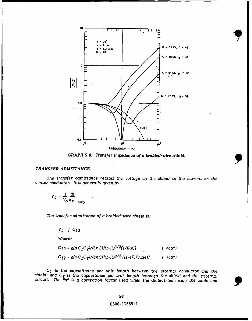
100
* . 30*
nd 63 mils K " 85.4%. e - 42
N t o
K - 9.5%. * 46
K - 94S%, @ -S2
-- /K - 97.8%. •5
0.1
lo a1 107
FREQUENCY - M&
GRAPH 5-8. Tranfer impedance of a braided-wire shield.
TRANSFER ADMITTANCE
The transfer admittance relates the voltage on the shield to the current on thecenter conductor. It is generally given by:
I dIv° dz v=o
The transfer admittance of a braided-wire shield is:
yt = ) C12
Where:
C 1 2 = g[wClC 2 )/(6cC))(1-K)3 / 2 [I1/E(e)) ( <450)
C 1 2 = g[njCC 2)/(6C)I(I-K)3 ! 2 [(1-e2)i /E(e)) ( >450)
C 1 is the capacitance per unit length between the internal conductor and theshield, and C 2 is the capacitance per unit length between the shield and the externalcircuit. The "g" is a correction factor used when the dielectrics inside the cable and
94
D500-11659-1

outside the cable are not the same. This is given as: g = 2 1/(1+,2). Where e1 isthe dielectric of the inner insulator, and c2 is the dielectric of the outer insulator ormedia (the outer jacket, if it is thick). If the outer jacket is thick, and is the sameas the inner insulator, g--1. For typical polyethylene insulated cable, this factor is 1.4.The transfer admittance can, in most cases, be omitted if an exact solution is not needed.EXAMPLE 5-4:
GIVEN: The cable in the preceding example is subjected to a shield currentthat rises exponentially to a 1KA with a time constant ," of2.5n, if the shield is woven from copper wire.
• ~ , A ( fall time)Where I(t) = 100e - tA and - a
FIND: The open-circuit voltage induced between the internal conductorand the shield for a 1 meter cable. We will neglect the mutualcapacitance.
SOLUTION: From the preceding example, the fill Is 0.776, and the coverageis 95%. The dc resistance is given by [(4/rd2 NCacos(a)] = 1.87milli-ohms/meter, and the diffusion time constant is T3 =au od2 = 1.87 microseconds. From Graph 5-7, and equation 5-20,the value of the eccentricity function is 1.14, and the value of(l-K)3 / 2 = 0.011. Using these -values in equation 5-23a, M 1 21.7 x 10⁻¹⁰. The transfer impedance can now be written:
Zt=1.87 x 10 - 3 (1.87 x 10⁻⁶jw)/sinh(1.87 lO"jw j)fi + jw(1.7 x 10- 10)
Where the first term is due to the diffusion of the field throughthe shield and the second term is from the inductive couplingof the field through the shield.
The responses to the two terms can be solved separately, andcombined by superposition later. The Voc induced by theinductance term can be obtained directly in the time domain,and i3:
Vm(t) = M121 di°(t) 3 5 e-t/T (volt-)2 dt
The response to the diffusion term is
Vd(t) I a 0.942
T > > Ts
TAPE-WOUND AND SPIRAL SHIELDS
Tape, or spiral shields are often used where flexibility of the shielded cable isrequired. However, they make a poor shield for preventing coupling of current to theinner conductor. This occurs because the shield spirals around the center conductor,creating a large mutual coupling term. For a large dio/dt(jw Io) the voltcze can become
95
DS00-11659-1

large enough to arc between the turns. This will reduce the inductance and actuallyimprove the shielding; however, the arc not only produces RF on the cable, which maybe a problem, (i.e., create RF in the passband of a receiver), but may damage the cable.For a single layer tape-wound shield, in which the turns do not overlap, or even touch,the voltage produced on the internal conductor is comprised of three (3) parts:
1) The diffusion of the axial part of the shield current through the wall of theshield.
2) The azimuthal internal impedance drop produced by the axial magnetic fieldinside the shield.
3) The inductance drop, resulting from the axial magnetic flux flowing throughthe spiral.
The parameters of a spiral shield are given as follows:
cos k = Where W is shield width, (Eqtn 5-24)2wa a is radius, and a is the
spiral angle -
N = sin C Where N is the number of (Eqtn 5-25)w turns per unit length.
ginHFIGURE 5-25. Important parameters of a spiral shield.
FIGURE 5-26. Spiral Shield.
96
Il~nn- 11 , i I

The transfer impedance Zt normalized to the dc resistance per unit length Roof a tubular shield of the same thickness T and radius a is:
Zt = [(I + P)T/611 + tan2s] + j(T/6o)2 (a/T)tan2 (a) i"M12Ro iinh [(I + j)T/4 Ro
Where is the skin di-pth -in the shield, and So is the skin depth for an equivalentnonferrous shield ( Uj= Po).
For low frequencies, T/6o<<, the transfer impedance increases with increasingspiral angle i. This could be expected, due to the fact that with a larger spiral angle,comes a more narrow tape width, and thus more turns per inch. At high frequencies,(T/6 D)>>I), the transfer impedance is dominated by the inductance term. It also increasesas the spiral angle increases. NOTE: THE CAPACITANCE BETWEEN THE TURNSHAS BEEN NEGLECTED IN DERIVING THE ABOVE EQUATION. This capacitanceis important at high frequencies, where the spiral-wound tape becomes self resonant.
EXAMPLE 5-5:
GIVEN: A tape- wound shield on a 1 cm radius cable is wound with a 10mil thick, 1 cm wide, copper tape, without overlap.
FIND: The dc resistance and the mutual inductance per unit lengthfor this shield.
SOLUTION: From equation 5-24, cos(a) = w/2a = 0.159 , or , = 80.80.The dc resistance with t/6 << !1&W
Rdc = RJ1 + tan20 O8)J = 42.7 milli-ohm/rm.
The mutual inductance is:
M12 =(Po/410tan 2 (a) = 3.85 z 10- 6 H/m.
Thi is four orders of magnitude greater than the value obtainedfor the braded-wilre aiekL
OVERLAPPED TAPE
-The HF characteristics of a single-layer overlapped shield with an overlap widthw o can be obtained by substituting w-w o for w in equations 5-24 and 5-25. The resultanttransfer impedance will be too large at low frequencies, by a factor of w/(W-wo), andthe capacitance between the overlap must be taken into account for very high frequenciesbecause it will begin to short out the inductance so that the magnitude of the transferimpedance will reach a maximum and then begin to decrease.
TAPE WITH GAP
If the tape-wound shield has a gap between the turns, it can be treated in a similarmanner as the overlapped tape. Just replace w in equations 5-24 and 5-25 with (w+Wo).For low frequencies, this "fix" will produce a value that is too low, by an amount
97
D500-1 1659-1

w/(w+wo). The leakage inductance of this shield is so large that the low frequencydiffusion is often of only passing interest. Since the optical coverage is less than 100%,there is a transfer admittance as well. This admittance is:
Yt = jwC 1 2
with
C 1 2 = (CiClwo2)/r64rEa2 cos(c)]
Where C1 and C2 are the capacitances per unit length, as previously defined andwhere:
C = permativity of insulation inside the cablea = shield radiusw o = gap between turnsa = spiral angle
This is good for all tape wound shields.
FERROMAGNETIC
The use of tubular shields made of ferromagnetic materials may be attractivefrom the viewpoint of high frequency shielding. However, the shielding is lost when pthe material becomes saturated. Also, ferromagnetic materials do not have the highconductivity that other materials have, therefore, they are not as good a shield as areconductive materials such as copper or aluminum. So they are not used generally asshielding materia
MULTIPLE SHIELDS
In order to improve the shielding of a cable, often times more than one shieldand/or type of shield is used. One way to find the transfer impedance and admittanceis to analyze each shield separately, until all shields have been accounted for. Anequivalent transfer impedance and admittance can usually be obtained in this mannerfor two layer shields, assuming that a standing wave is not supported in the transmissionline formed by the shields. In practice, this is a safe assumption if one of the followingis satisfied:
a. The frequencies that stimulate standing waves cannot penetrate the outershield (e.g., solid tubular).
b. The shields are in contact with each other at electrically short spacingsalong the cable.
c. The shield-to-shield transmission line is very long, and terminated in itscharacteristic impedance, or very lossy, so that reflections from the endsdo not build up standing waves.
98
D500-11659-1

CONNECTORS AND SPLICES
The connector or splice is also a source of EMP coupling. It can be visualizedas a region in the cable that may contain cracks or splits in the shielding, allowing theexternal EMP to couple to the internal region. Connectors and splices form such acomplex configuration that their transfer impedance and admittance are almost alwaysfound by testing. A typical connector test set-up is shown in Figure 5-27..
INSULATING% SUPPORT
• OUTER
RECTINNECR10 CONDUCTOR
TUBED
j/ PLATE
CORE OR SENSING
i . PLUG 0 ",
BULKHEAD .RECEPTACLE SHEL
TUBE
FIGURE 5-27. Connector Test Device.
MEASUREMENT OF SHIELDING
The transfer impedance of a cable shield is, as defined earlier, the Voc per unitlength induced on a conductor inside the shield by one ampere of shield current. Thetransfer admittance is the short circuit current per unit length produced by one voltof external shield potential. The most common method used to obtain these parameters,is by testing a section of the cable. One way to to test a cable is to use what is calledthe "rough test". In this test the cable in question is suspended in a conductive trough.It ... ,n driven in one of two ways depending on if the transfer impedance or admittance
. ," obtained.
!n the transfer impedance configuration, the conductive trough is connected tothe , - and drives the shield with a current (I,) negligible voltage, and the open circuit.oltog. (V )induced on the center conductor is recorded. The transfer impedanceis approxiaCted by:
Z = Voc/lo s (s << X))
99D500-] 1659-1

In the transfer admittance configuration, the conductive trough is isolated fromthe shield and developes a Voltage V, between the shield and trough. A short circuitcurrent I is then induced in the center conductor which has one end connected toground. ie transfer admittance can be found by:
Yt = Isc/Vols (Is<A
Where Vo is the voltage difference between the shield and the test set.
In both of the test configurations, the test sample "I" must be short, comparedto the wavelength of the excitation signal.
Another test currently being studied involves the use of a network analyzer suchas the HP3577A. The output of the network analyzer is connected to an inductivecoupling probe. This drives the cable shield. Another probe is used to measure thecurrent induced on the shield. This current is then divided into the voltage induced onthe center conductor. Figure 5-27a shows a typical set-up of the above described test.
NETWORKANALYZER
TERMINATIONC..ABLE
BOX
LRU
FIGURE 5-27a. Shielded cable tester setup.
A commonly used definition of the quality of a cable shield, is the shieldingeffectiveness, which is, for the purpose of this text, defined as:
S(dB) = 2 OlogIo/f
Where 10 is the current in the shield, and I is the current in the conductor insidethe shield.
APERTURE PENETRATION
Because the study of aperture penetration is best left to numerical methods, thissection will be more informative than theoretical It is intended to provide an insightto one method of modeling how EMP can be coupled through an aperture.
It can be shown that the electromagnetic field that penetrates through a smallhole in a conducting surface can be represented approximately by the radiation from
100.
D500-11659-1
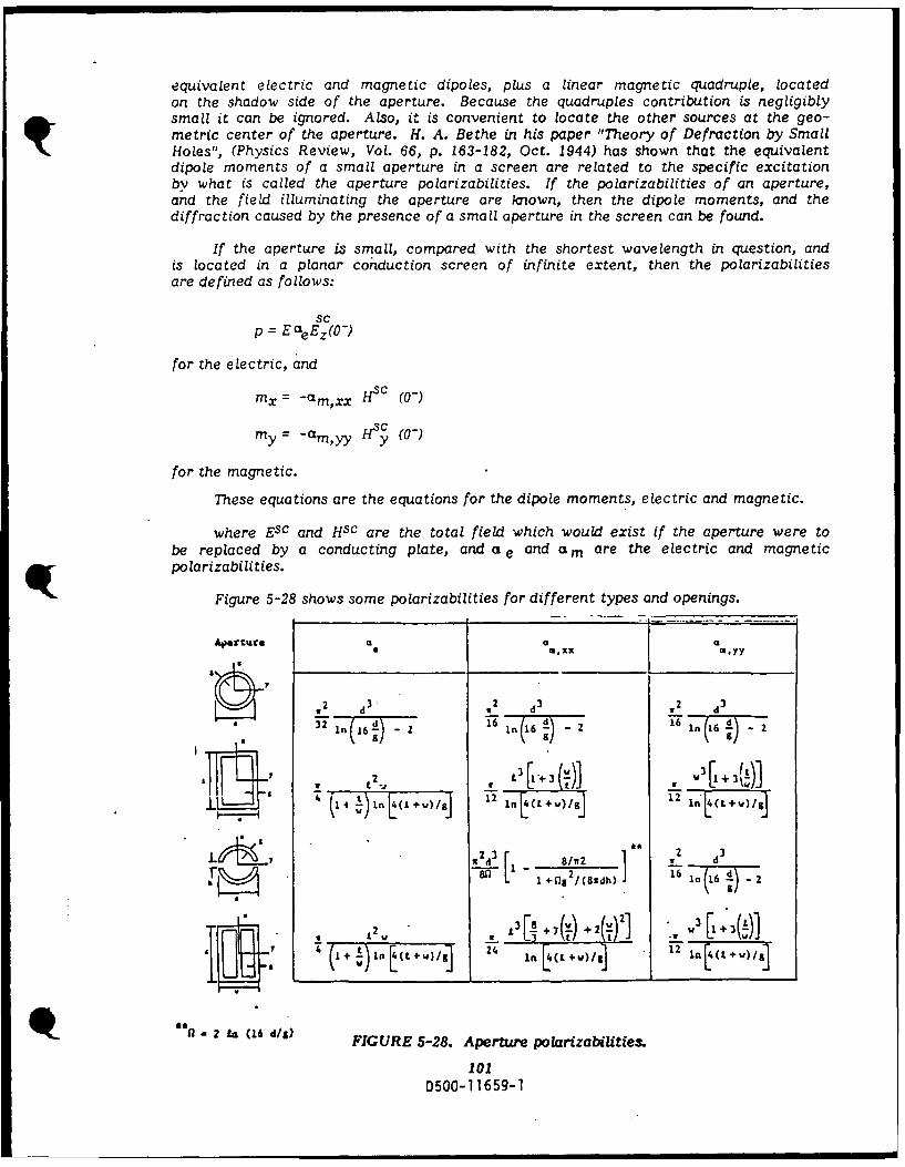
equivalent electric and magnetic dipoles, plus a linear magnetic quadruple, locatedon the shadow side of the aperture. Because the quadruples contribution is negligiblysmall it can be ignored. Also, it is convenient to locate the other sources at the geo-metric center of the aperture. H. A. Bethe in his paper "Theory of Defraction by SmallHoles", (Physics Review, Vol. 66, p. 163-182, Oct. 1944) has shown that the equivalentdipole moments of a small aperture in a screen are related to the specific excitationby what is called the aperture polarizabilities. If the polarizabilities of an aperture,and the field illuminating the aperture are known, then the dipole moments, and thediffraction caused by the presence of a small aperture in the screen can be found.
If the aperture is small, compared with the shortest wavelength in question, andis located in a planar conduction screen of infinite extent, then the polarizabilitiesare defined as follows:
sc
p = Ecefz(O-)
for the electric, and
mx = -am,xx Hsc (0-)
my = -am H (0-)
for the magnetic.
These equations are the equations for the dipole moments, electric and magnetic.
where Esc and Hsc are the total field which would exist if the aperture were tobe replaced by a conducting plate, and a e and am are the electric and magneticpolarizabilities.
Figure 5-28 shows some polarizabilities for different types and openings.
s 1M.XX m.yy
2 d 3 ,- 2 d- 832 d,3
-2 L3 - [ILW[I+3!t)] -
' 77}nJ2-)~J I (Lw/ 12
an 1 + 8fl2/(8"dh) 76 6 -2
O w 3 + d/.)7 ( + 2 w 3
W i q n [4(L +V)I a]2
f- 2 fa (16 dg) FIGURE 5-28. Aperture polarizabittie&
101D500-11659-1

The radiation from these dipoles is computed by standard methods, taking intoaccount the presence of the screen, and its effects. After some algebra, it can be shownthat the field produced by the dipole model is:
2W r 2 r 2 . nm I ( 2 J
EK e -J (rY- k2 3k ,m 3 (k2k~y 2w r E 2 - r 2 r r
1 e-j kr k.F 2 k 2 k2 L
(PC- r r m r
+n (x (k2.- J
for the electric field; and for the magnetic:
e - --Jyr + ym k 2 3k _
yx -P Y- ( k2 -J + M.(k2 J2 r 2
X 2w r ciq r r 2c r " r)
Hj 21 r _S_ (x) + m 2 _ j 3k) )
Z 2x r r2 x YY )
Any object which scatters energy back into- the aperture, further complicatesthe computation as it must be taken into account.
This model is good for distances far from the hole, i.e., greater than 5 to 10 timesthe hole size. However, caution must be used if it is applied close to the hole. Figure5-29 gives an idea of how the model varies from an accurate numerical solution fora iv/m incident field.
102
0500-11659-1

zz>0
dipole moment approximation - - - -
accurate numerical solution
, %IE9(r,0,9&,90°)
G-90 ° , 0
0.04 0.08 0.12
2. r-233. r-l0a
FIGURE 5-29. Electric field on shadow side of square aperture.
QPROTECTVE FEATURES
Now that we know how EMP is produced, what the waveform looks like, and howit can be coupled into a circuit, it is time to look at how to protect sensitive circuitsfrom the large voltages and currents. One type of protection, the shielded cable, hasalready been covered. However, shielded cables are only one kind of protective devicethat are at our disposal. Other types of devices are; filters, door seals, and screenson windows, just to name a few.
All of these will be discussed, and how they are used in combination to form acomplete protective barrier around the circuit.
ROOM OR CONTAINER
The room, or container, is the first line of protection against EMP penetration.It should be a perfectly conducting metal shield, completely enclosing the equipmentto be protected. This type of "box" is called a Faraday Shield. There are two problemswith this. First, there is no such thing as a perfect conductor. In a perfect conductor,a very thin "sheet" of metal would completely stop the EMP. In real metal, the EMPis reduced in an exponential form, exp(-Tz). Where Y is a complex value, and th.s hasan attenuation and a phase associated with it. The attenuation part is exp -[(wij01/2] .Where u is the permability, a is the conductivity, w is the radian frequency and z isthe distance the wave travels into the metal shield. Therefore, the thickness of themetal is important. It must be thick enough to stop the EMP, or at least reduce it toan amount that is acceptable, and not increase the weight more than necessary. Second,in most cases there are penetrations into the "box". Some are by conducting media
103D500-11659-1
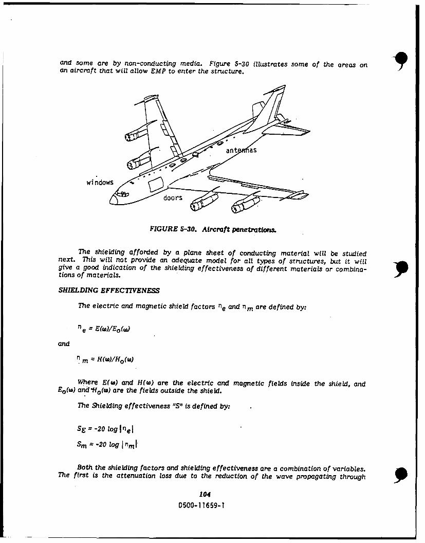
and some are by non-conducting media. Figure 5-30 illustrates some of the areas onan aircraft that will allow EMP to enter the structure.
wi ndows
FIGURE 5-30. Aircraft penetrations.
The shielding afforded by a plane sheet of conducting material will be studiednext. This will not provide an adequate model for all types of structures, but it willgive a good indication of the shielding effectiveness of different materials or combina-tions of materials.
SHIELDING EFFECTIVENESS
The electric and magnetic shield factors ne and nm are defined by:
e = E~W)/Eo(w)
and
n m H(w)/Ho(w)
Where E(W) and H(w) are the electric and magnetic fields inside the shield, andEo(w) and *Ho(w) are the fields outside the shield.
The Shielding effectiveness "S" is defined by:
SE -20 log Inel
sm -20 log I n,,
Both the shielding factors and shielding effectiveness are a combination of variables.The first is the attenuation loss due to the reduction of the wave propagating through
104
0500-11659-1
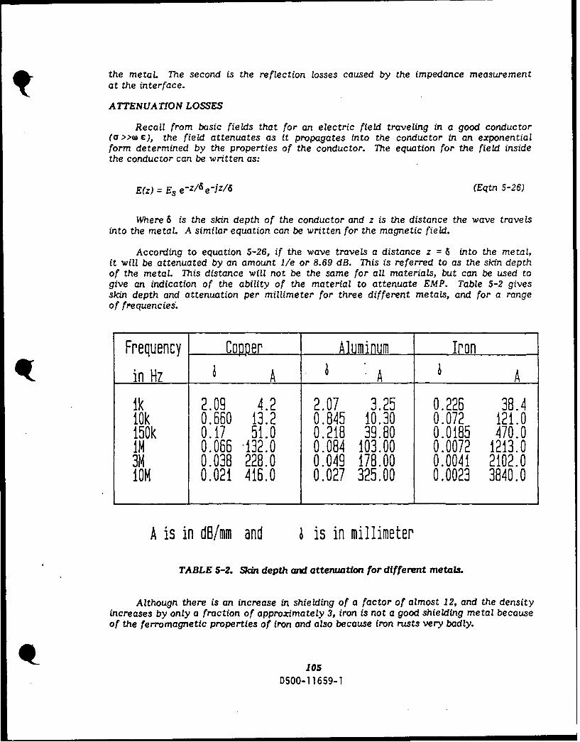
the metal. The second is the reflection losses caused by the impedance measurement
at the interface.
ATTENUATION LOSSES
Recall from basic fields that for an electric field traveling in a good conductor(7 >>w c), the field attenuates as it propagates into the conductor in an exponentialform determined by the properties of the conductor. The equation for the field insidethe conductor can be written as:
E(z) = Es e - z/ 6 ejz/6 (Eqtn 5-26)
Where 6 is the skin depth of the conductor and z is the distance the wave travelsinto the metal. A similar equation can be written for the magnetic field.
According to equation 5-26, if the wave travels a distance z = 6 into the metal,it will be attenuated by an amount lie or 8.69 dB. This is referred to as the skin depthof the metal. This distance will not be the same for all materials, but can be used togive an indication of the ability of the material to attenuate EMP. Table 5-2 givesskin depth and attenuation per millimeter for three different metals, and for a rangeof frequencies.
Frequency Copper Aluminum Iron
in Hz A A A
1k 2.09 4.2 2.07 3.25 0.226 38.41Ok 0.660 13.2 0.845 10.30 0.072 121.0150k 0.17 51.0 0.218 39.80 0.0185 470.0IN 0.066 '132.0 0.084 103.00 0.0072 1213.03M 0.038 228.0 0.049 178.00 0.0041 2102.0ION 0.021 416.0 0.027 325.00 0.0023 3840.0
A is in dB/mm and 4 is in millimeter
TABLE 5-2. Skin depth and attenuation for different metaL.
Although there is an increase in shielding of a factor of almost 12, and the densityincreases by only a fraction of approximately 3, iron is not a good shielding metal becauseof the ferromagnetic properties of iron and also because iron rusts very badly.
105D500-1 1659-1

REFLECTIVE LOSSES
The second factor mentioned earlier were the losses due to reflection. Wheneveran electromagnetic wave is incident on a boundary of materials with different impedancesthere will be a reflected wave and a transmitted wave. This reflection is, in general,dependent on not only the material, but also the angle of incident. The maximum trans-mitted wave will result from a normal incident. We will, therefore, concern ourselveswith this situation.
Because the transmitted wave, which is the part of primary concern, is dependenton the field at the interface, the field at the interface must be found. This field isaffected by the reflected wave. Skipping the intermediate math, and going directlyto the end result, the ratio of the total electric field at the surface to the incidentfield can be found. It is:
Te I Es = 2 Zm/Zoz = 0 Ei 1+Zm/Zo
= 2 Zm forZm << Z0
Zo
If the material is of finite thicless there is a second interface, and thereforea second reflection. Assuming a finite thickness, the overall shielding factor for a con-ducting sheet is:
e = Et = (4Zm/Zoe-Z/6 e-Jz/6 (Eqtn 5-27)
Ei (1+Zm/Zo)2
TOTAL LOSSES
For IZmI<< Zo . The shielding effectiveness can be expressed in the form:
S=A +R
Where A is the attenuation loss
A = 8.69z/6
and R, the reflection loss
R = 108 + lOlog(orlurf)
ar and Vr are conductivity and permeability values relative to copper, and f isfrequency in megahertz.
Equation 5-27 above is a good approximation, but only takes the first two reflectionsinto account.
The shielding factor for a plane of conducting material when all reflections aretaken into account is:
106D500-11659-1
l I I MM
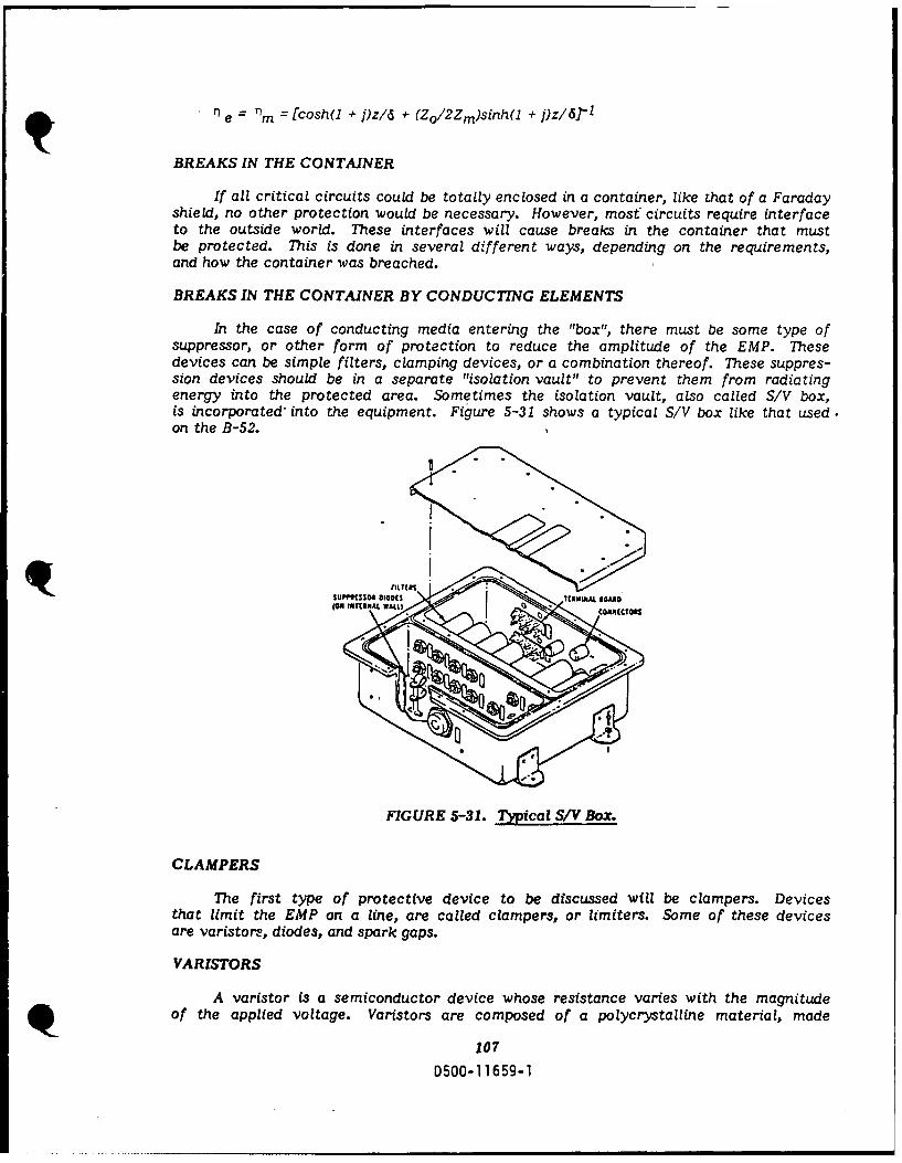
n e = nm = [cosh(l + j)z/6 + (Zo/2Zm)sinh(l + 1)z/d -
BREAKS IN THE CONTAINER
If all critical circuits could be totally enclosed in a container, like that of a Faradayshield, no other protection would be necessary. However, most circuits require interfaceto the outside world. These interfaces will cause breaks in the container that mustbe protected. This is done in several different ways, depending on the requirements,and how the container was breached.
BREAKS IN THE CONTAINER BY CONDUCTING ELEMENTS
In the case of conducting media entering the "box", there must be some type ofsuppressor, or other form of protection to reduce the amplitude of the EMP. Thesedevices can be simple filters, clamping devices, or a combination thereof. These suppres-sion devices should be in a separate "isolation vault" to prevent them from radiatingenergy into the protected area. Sometimes the isolation vault, also called S/V box,is incorporated' into the equipment. Figure 5-31 shows a typical S/V box like that used.on the B-52.
SUPPI!SsOd 010015(04 10I11UAL WrAu)
FIGURE 5-31. 7Tpical S/V Box.
CLAMPERS
The first type of protective device to be discussed will be clampers. Devicesthat limit the EMP on a line, are called clampers, or limiters. Some of these devicesare varistors, diodes, and spark gaps.
VARISTORS
A varistor is a semiconductor device whose resistance varies with the magnitudeof the applied voltage. Varistors are composed of a polycrystalline material, made
107D500-11659-1

by pressing and heating special mixtures of either silicon carbide, or oxides of zincand bismuth. This mixture produces a resistor that has a very large resistance whensmall currents are flowing, and a small resistance for large currents.
These devices can respond in nanoseconds. Metal-oxide varistors have a clampingvoltage, ranging from about 40 to 1500 volts, continuous power of up to 5 watts, anda peak energy of up to 160 joules. The bad thing about a varistor is that it reacts toany voltage change, and therefore is continually changing the impedance of the line.Impedance matching is very important on data, video and antenna lines. Figure 5-32shows the symbol and V-I characteristics of two different types of varistors.
Device Symbol V-I Characteristics
a) HOY(Metal- VOxide abVaristor]
1..
bi SiliconCarbide b_ ..Varistor "4 -3;, b(SiC]
FIGURE 4-'.'.. Symbols and V-1 characteristics of some variors.
DIODES
Diodes are also semiconductors, but they are junction devices (two or more typesof materials put together) as opposed to varistors that are bulk devices (all the sametype of material). Diodes perform the same function as do varistors; that of drainingoff the EMP energy. Diodes, however, act as switches. They do not effect the circuituntil the voltage reaches a threshold value. After this value is reached, the diode turnson, and limits the voltage on the line to some value determined by the type and numberof diodes in the circuit. It will also react to any voltage over the threshold, such aslightning or generator surges. The problem with diodes is that they can be damagedmore easily than varistors. After a large voltage surge, holes can be made in the barrierbetween the two materials. This has the effect of lowering the breakdown voltage.If enough holes are punched in the junction, the diode will start to "turn on" at a voltagethat is in the operation range of the circuit it is connected to. A more likely resultis after sufficient holes are "punched" in the junction of the device, it will fail in ashorted mode and send all signals above the new threshold to ground. There are severaldifferent types of diodes that are used. Standard rectifiers, bipolar forward, reversebreakdown (Zeners), and bidirectional breakdown (Duel Zeners). These devices canbe used individually or in combination to give the desired protection.
Figure 5-33 shows the symbol and V-I level for the four types of devices mentionedabove.
9108
D500-11659-1
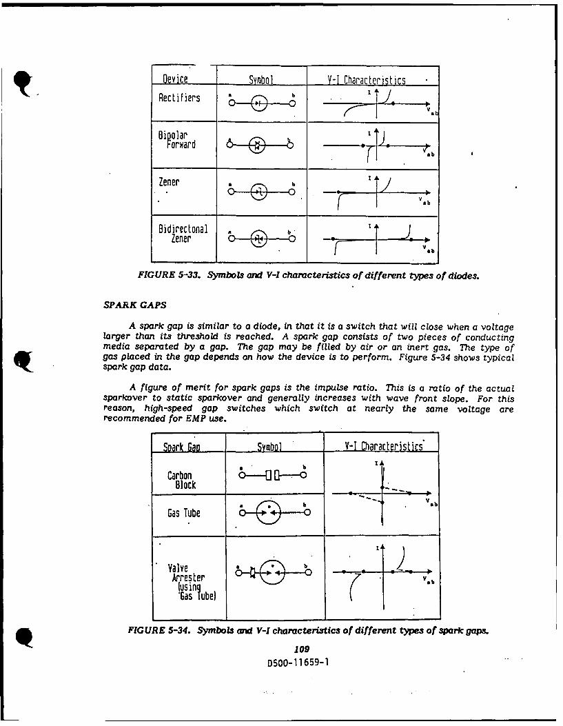
Device Symbol Y-I Characteristics
Rectifiers JVa
Bipolar o.
Zener J
Bidirectonal T JZener - :
ilab
FIGURE 5-33. Symbols and V-I characteristics of different types of diodes.
SPAK GAPS
A spark gap is similar to a diode, in that it is a switch that will close when a voltagelarger than its threshold is reached. A spark gap consists of two pieces of conductingmedia separated by a gap. The gap may be filled by air or an inert gas. The type ofgas placed in the gap depends on how the device is to perform. Figure 5-34 shows typicalspark gap data.
A figure of merit for spark gaps is the impulse ratio. This is a ratio of the actualsparkover to static sparkover and generally increases with wave front slope. For thisreason, high-speed gap switches which switch at nearly the same voltage arerecommended for EMP use.
Spark Gap Symbol V-I Characteristics
Carbon 0--- G-- -0Block
V, bGas Tube
ValveIrrester v, b(using .•.*Gas ?Ube)
FIGURE 5-34. SymboLs and V-I characteristics of different types of spark gaps.
109
D500-11659-1

FILTERS
Filters are used to selectively remove energy from the frequency spectrum. Theyare most often used after a clamping device to smooth out the signal that passes theclamping device. They also provide some EMP protection by their inherent filter proper-ties. Some of the different types of filters used are shown in Figures 5-35a & b. Thetype shown in Figure 5-35a is called a "T" filter. The type in Figure 5-35b, is a "pi"filter. The type in Figure 5-35b is the type used most often.
T. T TFIGURE 5-35a. T-Filter. FIGURE 5-35b. Pi-Filter.
CIRCUMVENTION
Circumvention is a technique in which the circuit is removed or shut off untilthe danger has passed. This method is widely used in computer circuits and in trans-mitters/receivers. Although this method is primarily used for EMP protection, it isalso used for TREE protection.
Other breaks in the container that fall into this classification are control cablesand hydraulic lines. Neither of these normally carry currents, but both are capableof having EMP energy coupled onto them and then transporting this energy into a pro-tected area.
CONTROL CABLES
There are many ways to prevent EMP from entering a protected area via controlcables. The first is by the use of conducting pulleys. Figure 5-36 shows a typical place-ment of conducting pulleys. These were found in the Boeing 747. Another device usedis a Dielectric Insertion Device (DID). The DID will isolate the inside part of the cablefrom the outside part. DIDs can be a problem in installation due to required mechanicalclearances for the control cables. A third way is by the use of a "guard tube" on theinput side of the Bulkhead. This guard tube acts as a waveguide below cutoff.
9110
D500-11659-1
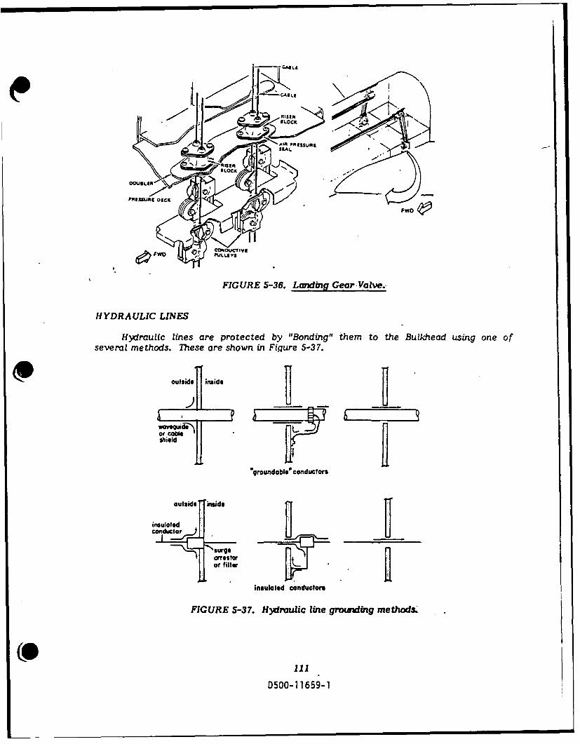
1LCAL.
.,SI~ ~
AIR PRESSURESEAL
PRISSUJI1 DICKc
FwO
O OUC7VE
FIGURE 5-36. Laninmg Gear Valve.-
HYDRAULIC LINES
Hydraulic lines are protected by "Bonding" them to the Bulkhead using one ofseveral methods. Thiese are shown in Figure 5-37.
outside inside
shield
groundabl* conductors
outside' iuide
insulated
or filterL
insulated conductors
FIGURE 5-37. Hydraulic Mie gmounding methods.
D500-1 1659-1

BREAKS IN THE CONTAINER BY NON-CONDUCTING ELEMENTS
Breaks in the container by non-conducting media still require some attention be-cause any break in the shield will allow EMP to enter the container. Some of the typesof breaks are: air vents, doors, access panels, and windows. Each of these will be lookedat separately, as each is approached differently.
AIR VENTS
Air vents require two types of protection. They must have EMP and radiationprotection. The latter will be discussed in the next sections. The most common formof EMP protection used on air vents is metal honeycomb ducting. (See Figure 5-39).This ducting acts as a waveguide below cutoff and prevents most of the energy fromentering the protected areas. The length of the ducting should be at least three timesthe size of the hole.
shield shieldshield
0 p
(a) singl aperture (b)many small (clarray of waveguidesapertures beyond cutoff
FIGURE 5-39. EMP penetration through different types of air vents.
ACCESS WAYS
Doors and access panels are another way EMP energy can penetrate a protectedarea. The gaps/voids between the door and door frame will allow EMP energy to enterthe structure. To prevent this from occurring, an RF shield in the fcrm of a seal orgasket is placed in this gap to attenuate the energy. Figure 5-39 shows a typical hardenedand non-hardened door.
112
D500-1 1659-1

WIR.E MESH OR
CONDUCTIVE FINISH
SEAL RETAINER
. BULB SEAL
SEAL. RET'A I EA
DOORRU STIBUBSA
DOOR
FIGURE 5-40. Hardened aid non-hardened doors.
The wire mesh or conductive finish and rub strips form an EMP seal around thedoor or panel. If this seal is damaged or improperly installed, the hardening will becompromised. It is also very important not to paint the area of the door frame wherethe rubber strip makes contact with the air frame. This will cause a potential. resistancebuild up.
WINDOWS
Windows are probably the most difficult penetration to harlen. They are necessaryto allow the pilot to see out, but the same opening that lets light in, will also let EMPenter. Unlike air vents, the window opening cannot be made a waveguide below cutoff.This would not allow the pilot to see out the window. Therefore, we must find anothersolution. One solution would be to cover the opening when the craft is in danger fromEMP. However, the craft could be in danger, and the crew not know it. Therefore,this is not a good plan. The next best thing is to embed a very conductive screen inthe window. This is a compromise between the ideal and a no solution. This will notcompletely stop the pulse, but will reduce it significantly. Figure 5-41 shows a typicalhardened window. This screen should be made of as highly a conducting material aspossible.
113
D500- 11659-1

OUTER SEAL
OUTER WINDOW PANE
0 WINDOW GRID FOR EPP PROTECTION
SPRING ASSY
/ SEAL
/..
SPRING RETAINER /1!'1
pAE/ / / iillRE ALI)
INNER WINDOW PANE
SEA
RETAINER
REVEAL
ETCHED GRIDWORK IS HELD IN PLACE AGAINST THE
STANDARD 707 WINDOW, USING A STAINLESS STEEL
RETAINER AROUND THE PERIPHERY. THE BRACKET CON-
TACTS NUTPLATES RIVETED ON THE PATCH STRUCTURE.
FIGURE 5-41. Overwmg Escape Hatch Window.
SUMMARY
EMP is generated by any above ground detonation, but only a high altitudedetonation will cause a pulse that extends far enough from the blast to be of concern.This HEMP is a by-product of a high energy explosion. It is a result of the Comptoneffect, gamma rays stripping off electrons. These Compton electrons spiral aroundthe earth's magnetic field. The resulting current, called "Compton current", is whatproduces the EMP.
The EMP has, in general, a double exponential form. It has a rise time of about10 nanoseconds and a time to one-half power of about 200 nanoseconds. This field canbe as high as 50kv/m and can, if detonated high enough, cover the continental UnitedStates.
If this field encounters any conductive material, it will induce a voltage and acurrent. The maximum theoretical voltage can be as high as 7.25 MV. This voltagecan only be obtained in a vacuum. The actual voltage and current must be obtainedby numerical methods. p
114
D500-11659-1
Protection from these large voltages and currents can be provided in a numberof ways, ranging from shielded cables, to protection at the terminating end of the cable.The cables can be solid tubes, braided wire, or spiral wound. Spiral wound cables,however, are not as good protection from EMP. Other forms of protection are Faradayshields, clamps, filters, and EMP gaskets for doors and access ways.
EMP can be coupled to buried cables because they are normally less than oneskin depth deep. The way EMP is coupled to buried cables will be briefly covered next.
9. 115
D500-11659-1
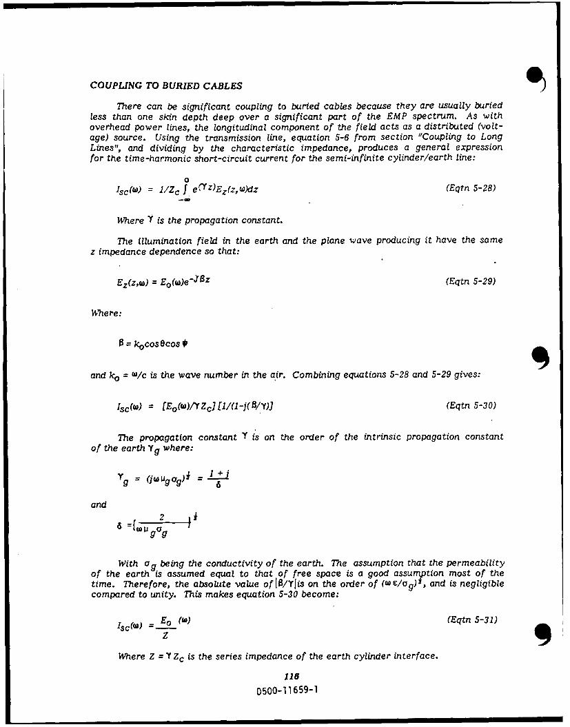
COUPLING TO BURIED CABLES
There can be significant coupling to buried cables because they are usually buriedless than one skin depth deep over a significant part of the EMP spectrum. As withoverhead power lines, the longitudinal component of the field acts as a distributed (volt-age) source. Using the transmission line, equation 5-6 from section "Coupling to LongLines", and dividing by the characteristic impedance, produces a general expressionfor the time-harmonic short-circuit current for the semi-infinite cylinder/earth line:
0
Isc(w) = I /Zc f e,'Z)Ez(zw )dz (Eqtn 5-28)
Where Y is the propagation constant.
The illumination field in the earth and the plane wave producing it have the samez impedance dependence so that:
Ez(z,w) = Eo(w)e- J 6Z (Eqtn 5-29)
Where:
8= kocosOcos,
and ko = w/c is the wave number in the air. Combining equations 5-28 and 5-29 gives:
Isc(w) = [Eo(W)/YZcJ[1/(1i-j(A/Y) (Eqtn 5-30)
The propagation constant Y is on the order of the intrinsic propagation constantof the earth Yg where:
g = (iuJgag) - 6
and
2
With ag being the conductivity of the earth. The assumption that the permeabilityof the earth is assumed equal to that of free space is a good assumption most of thetime. Therefore, the absolute value of 1/Ylis on the order of (w clOg) , and is negligiblecompared to unity. This makes equation 5-30 become:
Isc (w) = Eo (W) (Eqtn 5-3 1)
Where Z = Y Zc is the series impedance of the earth cylinder interface.
116
D500-1 1659-1

COATED CYLINDER
To obtain an explicit expression for the series impedance in a coated cylinder,wave scattering theory must be applied to the transmission-line formulation. The coatingrepresents a nonmetallic protective covering, usually placed on buried cables. Thecylinder, with a radius of "al" and a dielectric sleeve outer radius of "a", is assumedto be perfectly conducting. When the radius "a" is small, compared to the wavelengthsin both the medium i.e., copper, aluminum, etc., and the dielectric coating, the totallongitudinal current induced in the cylinder is:
= Ez/Z (Eqtn 5-32)
Where "Z" is a complex value given by:
Z = j° cos2(*)IntYokacos(P)1 + j w eclc - (k/w)2sin2 (*) In ao
2w T 2 w c a I
FIGURE 5-42. Coordinate systems for buried cables.
Where c c, i c, are the permativity and permeability of the coating, and k =CW(1)is the wave number in the medium. Y. = 1.781, and Ez is the component of the incidentelectric field, parallel to the cylinder. Equation 5-32 can also be applied to a cylinderthat is buried in the earth, provided that the radius is small relative to the skin depth 6and that the interactions between the field scattered by the cylinder, and the interfacecan be neglected. Ez is the electric field that penetrates to the cylinder, and k is thewave number in earth
k = -jYg = (1-j)/(6)
117
D500-1 1659-1
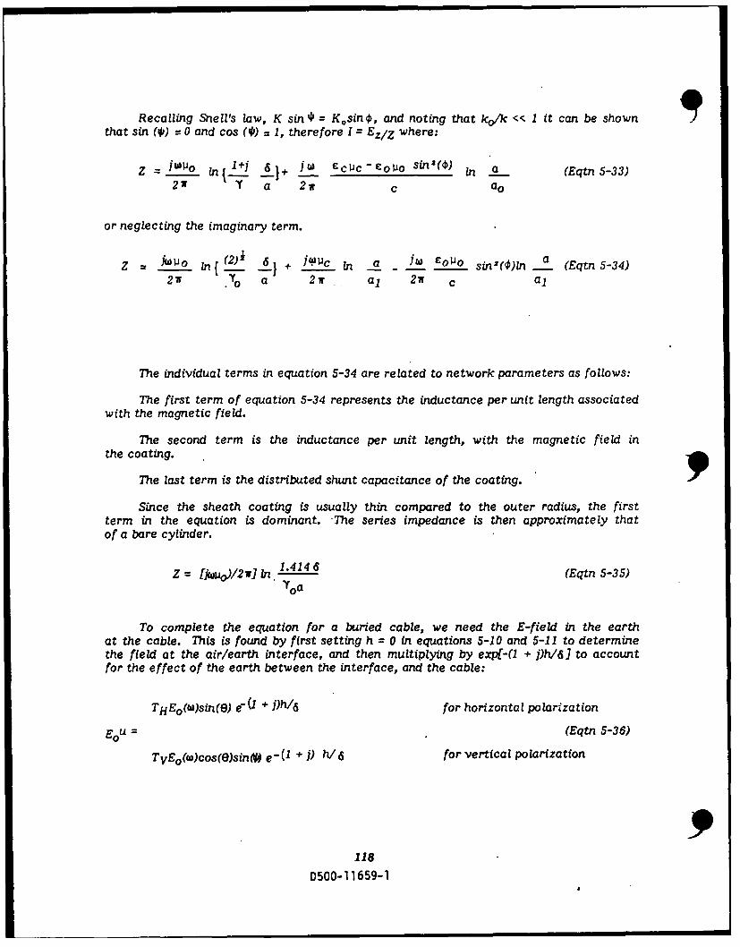
Recalling Snell's law, K sin * = Kosin 0, and noting that ko/k << 1 it can be shownthat sin (4p) = 0 and cos (I') = 1, therefore I = EzZI where:
Z = I 1in1+ j 6} 1JW £CUCc-Col o sin'() in .a (Eqtn 5-33)2w Y a 2w c ao
or neglecting the imaginary term.
Z 0 In{ (2) } + 14.'c In a - oJo sin(O)ln a (Eqtn 5-34)211 .{o a 2w a1 2w c al
The individual terms in equation 5-34 are related to network parameters as follows:
The first term of equation 5-34 represents the inductance per unit length associatedwith the magnetic field.
The second term is the inductance per unit length, with the magnetic field in
the coating.
The last term is the distributed shunt capacitance of the coating.
Since the sheath coating is usually thin compared to the outer radius, the firstterm in the equation is dominant. The series impedance is then approximately thatof a bare cylinder.
Z = Nion)/ 2 ) , 1.4146 (Eqtn 5-35)YOa
To complete the equation for a buried cable, we need the E-field in the earthat the cable. This is found by first setting h = 0 in equations 5-10 and 5-11 to determinethe field at the air/earth interface, and then multiplying by exp[-( + j)h/] to accountfor the effect of the earth between the interface, and the cable:
THEo(w)sin(O) e7 + j)h/ 6 for horizontal polarization
Eou = (Eqtn 5-36)
TVEo(w)cos(e)sin(# e-(1 + ) h/ 6 for vertical polarization
118
D500-11659-1

where
TH =I + RH 2(JwVj g)iSin(*)
TV 1 - RV 2(jbWo/Og)4[1/sin(0)]
At low frequencies, the ratio h/6 is small, therefore, the exponential functionvaries slowly. The losses in the earth are then negligible, and the field that penetratesto the cable is determined by the transmission coefficient (Th, Tv) at the interface.This coefficient increases with increasing frequencies at a rate of 10 dB per decade.At high frequencies where hi6 is no longer small, the exponential factor dominates.
SHORT-CIRCUIT CURRENT
The combination of equations 5-31, 5-35 and 5-36 gives the short-circuit sheathcurrent in a semi-infinite cable.
Isc( W) Eo(w) W e
Y . n (2 )i 6 6
"oa
Where Dh(*, e) = sin()sin(O), and Dv(* ,0)=cos(e) and no = 377 ohms. To obtainthe time-dependent current response to an incident pulse, the inverse transform mustbe evaluated (generally by numerical methods).
COUPLING TO TOWERS AND WAVEGUIDE RUNS
When a tower, or other tall conducting structure, is illuminated by an EMP, currentsare induced on the structure. Most of these currents will follow the low impedancepath to ground provided by the tower legs, and tower-ring ground shorting straps. Someof the current, however, will enter the building if precautions are not taken. Not onlythe tower, but the waveguide. runs can act as collectors of the EMP. Tests run by theBell System on a 100 meter high repeater station tower, with four waveguides and twoac conduits in Midlothian, Texas produced the following:
The measured currents were approximately damped sinusoids whose main frequencycomponent corresponded to the quarter-wavelength resonant frequency of the tower.Higher frequencies associated with the raceway and possibly the tower base were alsorecorded. The test results indicate that total penetration currents from horizontalfields are about 3500 amperes peak (when scaled to 50 Kv/m incident field). Half ofthis current was carried by the four waveguides and half by the two ac conduits. Thepenetration current for vertical fields is about 11,000 amperes, peak (scaled to 50 Kv/m).
An upper bound on induced tower current can be estimated by making two assump-tions; (1) The tower monopole and earth (the ground plane) are perfect conductors (nolosses in either), and (2) The incident EMP electric field vector is parallel to the axisof the cylinder, producing maximum coupling. With these assumptions, we can treata tower, or any tall metallic structure, as a simple receiving antenna.
119
D500-11659-1

IIN
~r
FIGURE 5-43. Typical tower tnaation. 9The induced dipole current in the frequency domain is: ID(W) = YD(w) E(w)
Where YD1W is the dipole-system transfer function and E(W) is the Foulier transform
of the incident EMP.YD = 'h so
30r [(0.I 2+ao2]
2 C[ 0.500 _Go =2where in tj T3 4 4 6 J .o h'P3.464h~~ ~ ~ -T 3.4419 6-
The magnitude of the dipole transfer function is a function of the height and
the radius, and is given as:n(2h/a)
Where 'h" is the height of the structure and a Is the radius.
Evaluating this equation shows that it peaks sharply near the fundamental half-wavelength resonant frequency of an ideal dipole. For a fixed 'h", the fundamentalresonance peak, and its associated bandwidth, increase as the dipole factor decreases(physical thicless increases). In general, the fatter dipole has a greater induced current.However, the antenna Q is higher for the thinner dipole, so that the induced currentoscillations do not damp out as rapidly on the thinner dipole. The induced tower currentcan be expressed as:
It= Io e-otsin(2v0ot) where Io = 3 T E o
120
0500-11659-1

Where so t.j the damping constant, fo = v/02K , c/h is the ringing frequency,and Io is the amplitude.
Za
hh
FIGURE 5-44. Comparison of tower aid a monopole antenna.
121
D500-11659-1

SECTION 6..
TRANSIENT RADIATION EFFECTS IN ELECTRONICS
With the increased use of solid state electronic devices in military aircraft, andan increasing awareness of nuclear events, the need for parts that are "hard" to radiationis becoming evident.
This section will look at how the different types of radiation produced by a nucleardetonation effects solid state devices. The first part of this section will cover howsemiconductors work. Next, how radiation affects semiconductors will be covered.Lastly, hardening measures will be covered. This will demonstrate how, by device selec-tion and design guidelines, a circuit can be made "hard" to Transient Radiation Effectsin Electronics (TREE).
TREE
"Transient Radiation Effects in Electronics," commonly abbreviated TREE, refersto the effects occurring in an electronics system as a result of exposure to the transientinitial radiation from a nuclear weapon explosion. (Note: transient applies to the radia-tion as it persists for only a short duration [I minute], not the response which may bepermanent.) The two types of radiation that are of most interest are: Gamma rays,and neutrons. Both of these can have detrimental effects on electronic devices andare present in many different energy levels. "TREE" is also the name applied to theconcept of developing information and techniques for predicting the effect of radiation
process in electronic materials.
In order to perform work on radiation hardening, a knowledge of how semiconductorswork is needed. To learn about how semiconductors work, a general knowledge of mater-ials is required. This section will therefore, start with a review of electronic propertyof materials. After this general base has been laid, there will be a quick discussionof how semiconductors work. This ground work allows the reader to better understandhow the effects of radiation on matter causes damage.
NATURE OF SOLIDS
All solids can be put into one of three classes; 1) Amorphous, 2) Polycrystalline,or 3) Crystalline. Amorphous materials are solids that have no discernible periodicstructures. An example of amorphous materials is sandstone. Polycrystalline materialshave patches of crystalline structures in them. Crystalline materials are those whichhave one complete constant periodic structure. The semiconductor studied in this textwill be of a crystalline type.
Although a pure crystalline structure would be ideal, this is very difficult to obtain.Companies go to great extremes to get as close as possible to a pure crystal.
The smallest unit cell that can be repeated to form the lattice is called a primitivecell. Three of the basic forms of a primitive cell are: 1) Simple cubic, 2) Body-centeredcubic, and 3) Face centered cubic. These are shown in Figure 6-1.
122D500-11659-1

Simple cubic Body-centered cubic Face-centered cubic
FIGURES 6-1a, b & c. Different types of cubes.
Each dot in the cube represents an atom. Any disturbance in this structure willalter the electrical characteristics.
Semiconductor materials have a diamond lattice structure, which can be describedas a face-centered cubic with four extra atoms at (a/4, b/4, c/4) from each atom ina fcc form.
a
FIGURE 6-1d. Diamond Lattice Structure.
Figure 6-1d shows how a diamond lattice structure can be drawn from a face-cen-tered cubic. The white dots stand for the atoms in an fcc unit. The black dots arethe added atoms from the fcc unit to become a complete diamond unit.
HOW SEMICONDUCTORS WORK
Electrons orbiting a single atom occupy distinct energy states, and no two electrons9can occupy the same energy state. As two or more atoms are brought close, these energy
123
D500-11659-1

states start to blur and become energy bands. Within the bands, are still distinct energystates. These electrons obey Fermi-Dirac statistics. The Fermi-Dirac distributionfunction gives the probability that an available energy state E will be occupied. Theprobability is given by equation 6-1.
F(E) = I (Eqtn 6-1)1 + exp(E-Ef)/KT
Where E is the energy state in question, Ef is the fermi level of the material,K = 8.62 X 10⁻⁵ev/OK = 1.35 X 10⁻²³ J/0 K. The fermi level, Ef, is the energy levelwhere the probability of the energy state being occupied, is 0.5. The energy bands andthe fermi levels are used to explain how semiconductors work.
The fermi level is halfway between the valence band and the conduction bandin intrinsic material. This is shown graphically in Figure 6-2a. In the figure, the valenceband represents the energy level of valence electrons in the outermost shell of an atom.There cannot be any conduction if all valence electrons are in this band. The conductionband is the energy band where electrons will be if conduction is to take place.
An atom of a pure intrinsic semiconductor material shares it's valence electronsto four adjacent atoms to produce covalent bonds for a stable form. There are no freeelectrons that have an energy level in or nec the conduction band, so that they canbe set free at OK. Semiconductor materials can be given electrical characteristicsto make them more useful by "doping" them with impurity atoms that create eitheran excess of free electrons or holes.
A semiconductor material, which is doped with atoms that have excess free elec-trons is n-type semiconductor, or holes, making it a p-type semiconductor. Figures6-2b and c show the energy bands of an n-type and p-type semiconductor, respectively.For n-type material, the fermi level will be closer to the conduction band, and p-typecloser to the valence band.
Ec
EF -
P-TYPE NORMAL -N-TYPE
FIGURE 6-2ab & c. Energy diagrams for different types of materiaL.
DIODES
A diode is made by combining an n-type and p-type semiconductor. When p-typeand n-type materials are combined, the fermi levels line up and produces a "potentialbarrier" across the junction, as shown in Figure 6-3a. 9
124
D500-11659-1

When a sufficient voltage source is connected to the diode in a way such thatthe negative terminal of the source is connected to the n-type material, and positiveterminal to the p-type, the majority of the carriers will overcome the "potential barrier"and produce a current. The applied voltage is called the forward bias, and is shownin Figure 6-3b.
If an external source is applied opposite to the above connection, the positiveterminal of the source to n-type and negative, p-type, the barrier will become larger,and very little current will flow. This applied voltage is called the reverse bias, andis shown in Figure 6-3c.
POTENTIALBARRIER
4 -4-
DIODE CONFIGURATION (A)
N P G
SCONVENTIONAL---CURRENT --
CIRCUIT CONNECTIONFORWARD BIASING
(a)
POTENTIALBARRIER
NO CURRENT FLOWFLOlW
CIRCUIT CONNECTIONREVERSE BIASING
(C)
FIGURES 6-3a, b & c. Energy diagram of a diode.
125D500-11659-1

TRANSISTORS
There are two types of bipolar transistors, n-p-n, and p-n-p. All of this discussionwill be over p-n-p, but the same principles apply to n-p-n.
A junction transistor is a semiconductor device composed of three adjoining, alter-nately doped regions. The first region, the emitter, is a heavily doped p-type. Thenext region, the base, is a doped n-type, but not as heavily as the emitter. The lastregion, the collection, is doped p-type, but not as heavily as the emitter. This producesa p-n-p configuration, or back to back diode.
This p-n-p setup is what allows a transistor to provide power gain. Figure 6-5shows an energy diagram for a p-n-p transistor in thermal equilibrium.
•+4- -4- +±4 + -4- 44-+ + + p EMITECOLLECTOR + - ++P EITTER
+ 4- 4 4- - -4- -4-
BASE
FIGURE 6-4. Transistor configuration.
As can be seen in Figure 6-5a, there is a "potential barrier" preventing the flowof either holes or electrons. If a forward bias voltage is applied to the Emitter-Basejunction, and a reverse bias voltage to the Collector-Base junction, as shown in Figure6-5b, the barrier between the base and the emitter is lowered, and the barrier betweenthe base and the colkuctor is increased. This will allow charge to flow in only one direc-tion. After a charge has passed the "junction of origin", it is, for the most part, quicklyswept away by the field produced in the transistor. For a very small base current, alarge collector current can be contracted.
* go
00 0
FIGURE 6-5a. Energy diagram of a transistor. 9126
D500-11659-1

MAJORITY MAJORITY-CARRIERS CARRIERS
EMITTER e 0C 0 0 ® P OLLECTOR
N p__( OG
BASEFORWARD REVERSE
CURRENT CURRENT
r~ 1+FIGURE 6-Sb. Biasing a transistor.
FIELD EFFECT TRANSISTOR
A Field Effect Transistor (FET), operates on a different principle than the transis-tor. An FET operates by changing the width of a channel through which the chargeflows. For example, look at a p-channel Field Effect Transistor (PFET), Figure 6-6a.
+++ +0+ + +++ + -_-+ ++Np -+ + + +++1+L- +--- ++ -+ -+P+ + + + +P+ N + + + + 3
Z + + +--+++Z: ZZ + +P. + + -
FIGURES 6-6a & b. Field Effect ransistors.
As the size of the N region in Figure 6-6a grows, the resistance from the sourceto drain goes up. Some FET's are designed to be normally conducting as shown in Figure6-6a, and some are designed to be normally non-conducting as shown in Figure 6-6b,but they both work on the same principle.
SILICON CONTROLLED RECTIFIER
A Silicon Controlled Rectifier (SCR) is a device composed of four alternatelydoped layers. This arrangement produces a device which, in it's off state, blocks currentflow from either direction because there are two potential barriers. It can, however,be enabled to conduct in one direction by appropriate signal being applied to it's gate.This signal reduces one of the barriers, and allows current to flow.
127D500-11659-1

E.. \ ..
EFoo 00
0 00
Figure 6-7. SCR Energy diagram at rest.
After the proper signal is applied to the gate and the current starts to flow, thecurrent flow itself will, if above the hold current, keep the SCR on.
EC - --
Ec
0 000
0
FIGURE 6-8. SCR energy diagram in lon" state.
HOW RADIATION EFFECTS SEMICONDUCTORS
Radiation can be measured in two different ways. One is the exposure level ofradiation that is measured in Roentgen and defined by:
1 Roentgen = 2.58 10- 4 coulomb/kg
The other is by the total dose, Rad, and is equivalent to:
I Rad = 100 ergs per gram
Different materials absorb this energy at different rates. Therefore, you mustnot only know the exposure level roentgens, but also, the way the particular materialabsorbs radiation, before you can discuss the total dose.
A more in-depth look into the nature of solids can be found in "Solid State ElectronicDevices," by Ben G. Streetman, or in "Physical Electronics," by Ferry-Fannin.
Of all the nuclear radiation released from a burst, alpha, beta, gamma andneutrons, only the last two are of primary concern. Alpha and beta particles are stoppedby a very thin piece of material, whereas gamma and neutrons are not as easily stopped.Of these two, neutrons generally cause most of the permanent structural damage.Although gammas can produce structural damage, the effects are small, so they willbe ignored. Also, neutrons can produce gamma rays, but again the amount producedis small
Neutron Fluence is defined as, "The time integral of neutron flux over total exposuretime". Neutron Flux is the product of the Neutron density and average velocity (Fluenceis flux times time). Since Fluence and Flux units do not indicate it's energy, the neutronsof interest must be specified. Therefore, a I Mev equilibrium ratio is a common refer-ence. Table 6-1 shows some common radiation and how they compare.
128
D500-11659-1
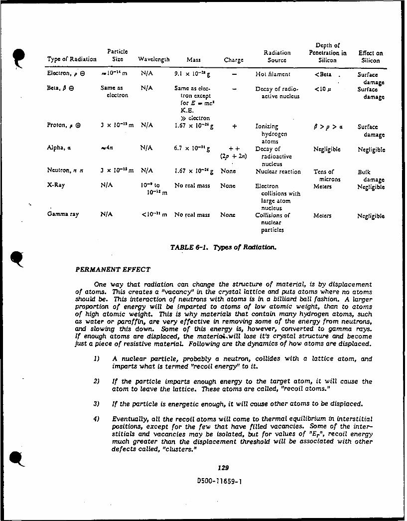
Depth ofParticle Radiation Pcnetration in Effect on
Type or Radiation Size Wavelength Mass Charge Source Silicon Silicon
Electron, P e 10-1 m N/A 9.1 x 10- 8 g - Hot filament <Beta Surfacedamage
Beta, P E Same as N/A Same as clec- - Decay of radio. < 10 u Surfaceelectron tron except active nucleus damage
for E - mcK.E.>> clectron
Proton, p (9 3 x 10-"rm N/A 1.67 x 10⁻²¹g + Ionizing P >p > a Surfacehydrogen damageatoms
Alpha, c w4n N/A 6.7 x 10" g + + Decay of Negligible Negligible(2p + 2n) radioactive
nucleusNeutron, n n 3 x 10- 1 Sm N/A 1.67 x 10⁻²⁴ g None Nuclear reaction Tens or Bulk
microns damageX-Ray N/A 10- to No real mass None Electron Meters Negligible
10-" im collisions with
large atomnucleus
Gamma ray N/A <10-11m No real mass None Collisions of Meters Negligiblenuclearparticles
TABLE 6-1. Types of Radiation.
PERMANENT EFFECT
One way that radiation can change the structure of material, is by displacementof atoms. This creates a "vacancy" in the crystal lattice and puts atoms where no atomsshould be. This interaction of neutrons with atoms is in a billiard ball fashion. A largerproportion of energy will be imparted to atoms of low atomic weight, than to atomsof high atomic weight. This is why materials that contain many hydrogen atoms, suchas water or paraffin, are very effective in removing some of the energy from neutrons,and slowing this down. Some of this energy is, however, converted to gamma rays.If enough atoms are displaced, the materiaA.will lose it's crystal structure and becomejust a piece of resistive material Following are the dynamics of how atoms are displaced.
1) A nuclear particle, probably a neutron, collides with a lattice atom, andimparts what is termed "recoil energy" to it.
2) If the particle imparts enough energy to the target atom, it will cause the
atom to leave the lattice. These atoms are called, "recoil atoms."
3) If the particle is energetic enough, it will cause other atoms to be displaced.
4) Eventually, all the recoil atoms will come to thermal equilibrium in interstitialpositions, except for the few that have filled vacancies. Some of the inter-stitials and vacancies may be isolated, but for values of "Er", recoil energymuch greater than the displacement threshold will be associated with otherdefects called, "clusters."
129
D500-11659-1

5) Thermal energy of the crystal causes some of the defects and defect clustersto migrate through to the crystal
6) Eventually, the mobile defects will either anneal by recombination of vacan-cy-interstitial pairs, become immobilized by the formation of stable clusters,or escape to a free surface.
As defect clusters are forrmed, the electrical characteristic of the device is de-graded. After the Neutron radiation is removed, the material will start to return tothe preradiated condition. It will not, however, return completely to the preradiatedstate.
TRANSIENT EFFECT
The other type of damage and ionization is primarily caused by gamma radiation.The primary interaction of gammd and x-rays with material occurs through the mechanicsof; 1) Photoelectric Effects, 2) Compton Scattering, and 3) Pair Production. Photoelec-trons are produced by Electromagnetic Waves (EMW), light, x-rays, and gamma raysstriking the material If the energy of the EMW is equal to or greater than the bandgap, one or more electrons are placed into the conduction band, thus raising the con-ductivity of the material. Photoelectrons are produced by low level gamma rays. Gammarays of higher energy levels interact by the Compton effect. The Compton effect,as described earlier, is where electrons are stripped off the atom. For very high energygamma, Pair Production is the method of energy transfer. This can occur with energiesof 1.02 Mev or greater, but it is a rare event and is normally neglected.
DIODES
Diodes can be affected by both displacement and ionization. Displacement effectcauses degradation in crystalline structure of the diode and converts the structure tothe polycrystalline form. In this structure, the fermi level will tend toward a commonvalue and the barrier is reduced. Ionization effect generates electron-hole pairs inthree regions: P, N and depletion region of a diode. Minority carriers in the bulk Pand N regions diffuse to the junction, and are swept across the depletion region by thebarrier potential across the junction. Carriers that are generated within the depletionregion also drift by the field associated with the depletion region. Figure 6-9 showsthe traveling direction of carriers in all three regions under the field across the depletionregion.
The nuclear radiation effects on a diode in a particular circuit can be realizedby:
1. The forward voltage of the diode is usually increased because of changes in resistivi-ty and mobility of the semiconductor material
2. The dynamic forward resistance will increase because of changes in resistivityand mobility modulation.
3. The reverse current increases because of increasing in carrier generation in semi-conductor material.
4. Since the resistivity increases, the reverse breakdown voltage will increase.
5. The switching characteristic of the diode will be changed due to an increcase inthe rise time and decrease in the storage time caused by lifetime damage.
130
D500-11659-1
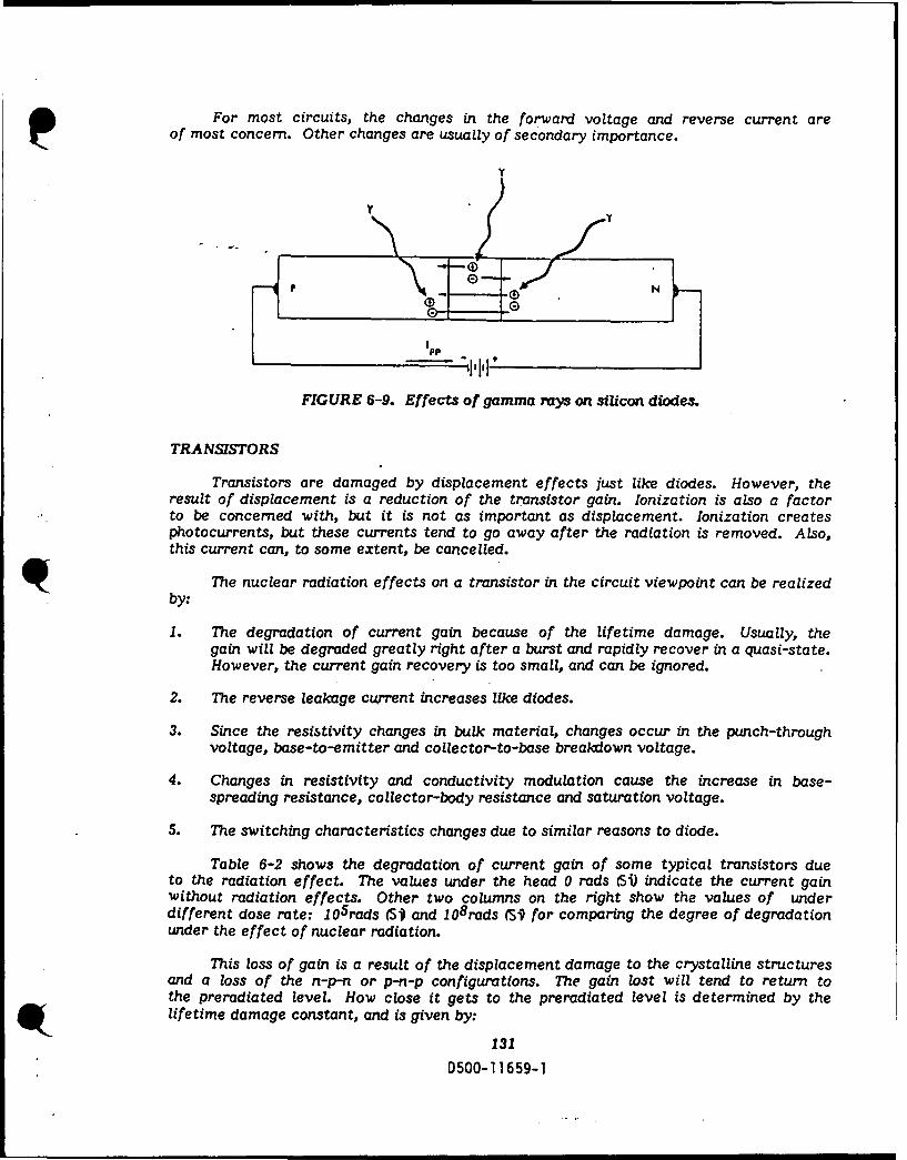
For most circuits, the changes in the forward voltage and reverse current areof most concern. Other changes are usually of secondary importance.
Y
FIGURE 6-9. Effects of gamma rays on silicon diodes.
TRANSISTORS
Transistors are damaged by displacement effects just like diodes. However, theresult of displacement is a reduction of the transistor gain. Ionization is also a factorto be concerned with, but it is not as important as displacement. Ionization createsphotocurrents, but these currents tend to go away after the radiation is removed. Also,this current can, to some extent, be cancelled.
The nuclear radiation effects on a transistor in the circuit viewpoint can be realizedby:
1. The degradation of current gain because of the lifetime damage. Usually, thegain will be degraded greatly right after a burst and rapidly recover in a quasi-state.However, the current gain recovery is too small, and can be ignored.
2. The reverse leakage current increases like diodes.
3. Since the resistivity changes in bulk material, changes occur in the punch-throughvoltage, base-to-emitter and collector-to-base breakdown voltage.
4. Changes in resistivity and conductivity modulation cause the increase in base-spreading resistance, collector-body resistance and saturation voltage.
5. The switching characteristics changes due to similar reasons to diode.
Table 6-2 shows the degradation of current gain of some typical transistors dueto the radiation effect. The values under the head 0 rads (Si) indicate the current gainwithout radiation effects. Other two columns on the right show the values of underdifferent dose rate: 105 rads (S and l08 rads (S for comparing the degree of degradationunder the effect of nuclear radiation.
This loss of gain is a result of the displacement damage to the crystalline structuresand a loss of the n-p-n or p-n-p configurations. The gain lost will tend to return tothe preradiated level. How close it gets to the preradiated level is determined by thelifetime damage constant, and is given by:
131D500-11659-1

TOTAL DOSE INDUCE 8 DEGRADATION IN ACTIVELY IRRADIATED TRANSISTOR
ISAMPLE IMEASUREMENT MAVERAGE)TYPE/MFG. SIZE IC 0 rads(Sl) 105 rads(Si) 106 rads(Si)
12N2222A/MOT 10 5 103 52.8 36.9
N 50 109 86.5 66.42N2369A/NAT 0 66.5 60 41.8
1 50 59.5 54.5 40.5
2N2432A/TI 10 0.1 138 - 8.84
10 201 - 682N2484/MOT 10 0.02 175 69.1 31.9
5 348 221 148
2N2605/NAT 8 0.1 199 163 751 206 181 103
2N2658/SOL 10 5 147 60 29500 225 181 138
2N2812/AP 8 10 115 65 33
I 1000 136 113 862N2857/MOT 10 0.1 61.4 28.5 17.5
2 80.9 51.5 35.1
2N2905A/MOT "10 10 132 131 127100 147 145 140
2N2907A/FC 10 0.2 112 118 81.8
10 149 161 1262N2920/TI 20 0.1 292 168 44.5
I1 326 235 103
2N2946A/T1 10 1 188 145 42.810 146 124 56.3
2N3019/MOT 10 10 116 89.9 59.950 135 123 92.9
2N3055/SEN 8 300 107.5 102.5 753000 46 44 32
2N3499/MOT 8 30 205 175 117150 106 103 77
2N3501/MOT 10 1 93.5 52.3 30.7
10 132 90.4 66.1
2N3506/MOT 8 100 96 85 521000 107.5 104 82
2N3507/MOT 8 100 65 50.5 33
1000 64 60 48
2N3509/MOT 5 1 59.2 34.8 28.310 88.1 62.4 49.2
2N3553/RCA 10 10 20.2 15.3 9.22100 35 29.9 20.7
2N3700/PCH 10 1 96.3 62.4 43.850 151 121 103
2N3749/AP 8 100 62 59 44.5
500 72 67.5 50
2N3752/SOL 10 100 117 87.4 78.5
1000 97.4 89.6 76.9
2N3810/MOT 10 0.1 217 198 140
2 2 T 31 220 177
TABLE 6-2.
132
0500-11659-1

TOTAL DOSE INDUCE 8 DEGRADATION IN ACTIVELY IRRADIATED TRANSISTORS
SAMPLE MEASUREMENT _ _ AVERAGE _
TYPE/MFG. SIZE Ir 0 rads(SI) 1O5 rads(Si) 100 rads(Si)
2N3866A/RCA 8 10 76 62.5 35100 71 63 43.5
2N3960/MOT 6 1 155 133 6530 122 112 82.5
2N3997/TI 8 10 118 78 46
1000 170 148 1052N4150/UNI 4 10 70 35 0.5
100 86 62 32.5
2N4405/INT 8 0.1 128 90 3610 165 147 106
2N5003/SOL 10 10 77.2 70.1 41.7
500 84 779 54.92N5005/SOL 10 1 77.2 70 . 41.72N5090/RCA 10 2 51.5 43.5 26.72N5108/MOT 8 1 27 15.8 4.5
100 30.8 25.4 152N5152/ 4 10 61 50 36
100 75 69 572N5153/SOL 10 1 98.7 86.9 57.9
100 152 143 1012N5237/GS 8 100 83.5 78 58
300 90 89 702N5250/SOL 4 200 70 44.5 25.5
2000 78 67 48.52N5326 /TRW I050 98.4 88.8 78.8
1500 116 115 108
2N5347/MOT 40 100 82 74.5 63500 85 79.5 71
2N5470/RCA 10 5 57.1 41 28.550 53.1 45.5 35.9
2N6187/MOT 14 300 91 72 46
3000, 76 59.5 39.52N6266/RCA 10 50 36.8 27.5 12.9
100 37 28.1 14.7
2N6267/RCA 10 10 49.7 35.3 13.7
100 53.3 41.5 20.9
TABLE 6-2. continued.
133
D500-11659-1
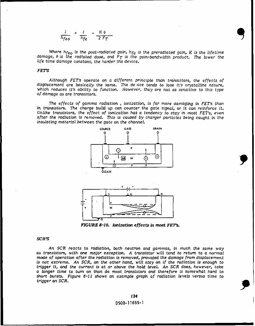
S =I +KO
hfeo hfe 2 FT
Where hfeo is the post-radiated gain, hfe is the preradiated gain, K is the lifetimedamage, 0 is the radiated dose, and FT is the gain-bandwidth product. The lower thelife time damage constant, the harder the device.
FET'S
Although FET's operate on a different principle than trahsistors, the effects ofdisplacement are basically the same. The de ice tends to lose it's crystalline nature,which reduces it's ability to function. However, they are not as sensitive to this typeof damage as are transistors.
The effects of gamma radiation , ionization, is far more damaging in FET's thanin transistors. The charge build up can counter the gate signal, or it can reinforce it.Unlike transistors, the effect of ionization has a tendency to stay in most FET's, evenafter the radiation is removed. This is caused by charger particles being caught in theinsulating material between the gate on the channel.
SOURCE GATE DRAIN
P
G N"
P
TGATE
FIGURE 6-10. Ionization effects in most FET&
SCR'S
An SCR reacts to radiation, both neutron and gammas, in much the same wayas transistors, with one major exception. A transistor will tend to return to a normalmode of operation after the radiation is removed, provided the damage from displacementis not extreme. An SCR, on the other hand, will stay on if the radiation is enough totrigger it, and the current is at or above the hold level. An SCR does, however, takea longer time to turn on than do most transistors and therefore is somewhat hard toshort bursts. Figure 6-11 shows an example graph of radiation levels versus time totrigger an SCR.
134
0500-11659-1

~TURN -ON'j
/L RN-ONNL/7
PULSE WIDTII
FIGURE 6-11. Typical SCR dose rate threshold characteristics.
HOW TO HARDEN AGAINST TREE
Circuit hardening can be described as any method that improves the radiationtolerance of the circuit. In order to engage in a hardening program, a knowledge ofthe following areas is mandatory.
a. The anticipated radiation environmentb. Functional requirements of the circuit including acceptable operationc. Component response to radiation
Without an understanding in all three areas, no worthwhile hardening programcan exist. One of the problems that an S/V engineer (who is not knowledgeable in allthree areas) may have is: hardening to one variable, several orders of magnitude morethan another. e.g. Does it make sense to harden to an exposure rate of 101 2rad/sec,only to have the circuit fail due to neutron displacement?
An S/V engineer who has a good understanding of all these areas can maintaina balanced hardening program.
Radiation effects on semiconductor devices are best explained by obtaining thegeneral admittance matrix equations containing all of the basic semiconductor propertiesthat undergo changes when exposed to the radiated environment. This can be very hardto obtain and difficult to work out by hand for complicated circuits.
Still, hand calculations can be used for simple circuits to get a ball park figureas to how the circuit will behave. However, if "exact" solutions are needed, or if thecircuit is complex, computer programs are needed. Figure 6-12 shows a typical modelfor a diode. This figure is intended to give an insight as to how complicated radiationmodels are.
135
D500-1 1659-1
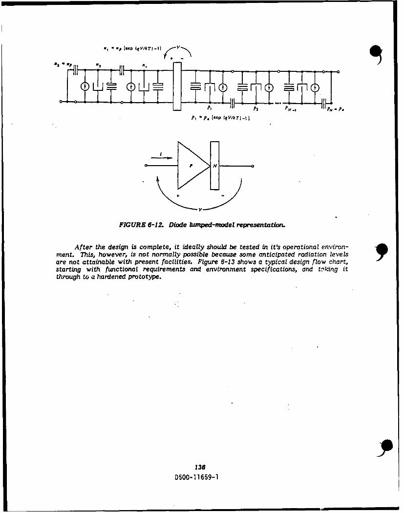
M - I xp (q /I-1 I I I
LP2 PH .1 P P,
P1 e, (exp (qV/kT) -I]
V_
FIGURE 6-12. Diode lumped-model representation.
After the design is complete, it ideally should be tested in it's operational environ-mernt. This, however, is not normally possible because some anticipated radiation levelsare not attainable with present facilities. Figure 6-13 shows a typical design flow chart,starting with functional requirements and environment specifications, and t,,Yking itthrough to a hardened prototype.
136
0500-1 1659-1
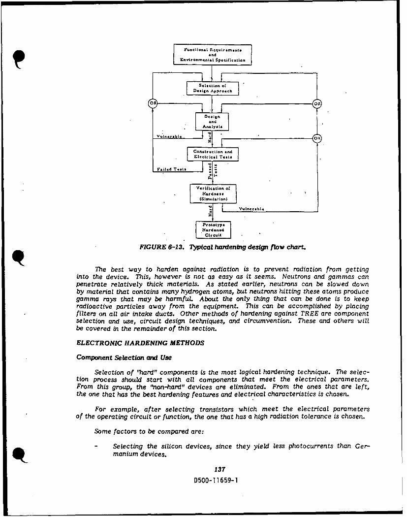
T onc t Rquirementin~andEnvironmenl l Specifcation
,I .I F_
Sosterection ofad
C eSlectionnSetnnU
Selectio of "har" compo esisn tpahemsloiahrdngtcnqu.Teee-
arales en t ue a
of the opeating ciruit orfu Conton tata ihraito oeanei hsn
maniumica devices
137
eri ficato o 1Hardness
(Simnulation)
I] Vulnerable
.HardltedLCircuit
FIGURE 6-13. Typcal hardentg deign flow charM
The best way to harden against radiation is to prevent radiation from getting
into the device. This, however is not as easy as it seems. Neutrons and gammas can
penetrate relatively thick materials. As stated earlier, neutrons can be slowed down
by material that contains many hydrogen atoms, but neutrons hitting these atoms produce
gamma rays that may be harmful. About the only thing that can be done is to keep
radioactive particles away from the equipment. This can be accomplished by placing
filters on all air intake duct. Other methods of hardening against TREE are component
selection and use, circuit design techniques, and circumvention. These and others will
be covered in the remainder of this section.
ELECTRONIC HARDENING METHODS
Component Selection ard Use
Selection of "ard" components is the most logical hardening technique. The selec-
tion process should start with all components that meet the electrical parameters.
From this group, the non-hard" devices are eliminated. From the ones that are left,
the one that has the best hardening features and electrical characteristics is chosen.
For example, after selecting transistors which meet the electrical parameters
of the operating circuit or function, the one that has a high radiation tolerance is chosen.
Some factors to be compared are:
Selecting the silicon devices, since they yield less photocurrents than Ger-
~manium devices.
137
D500-11]659-1

Selecting devices with high cut-off frequencies, which have a narrow band-
width.
- Selecting transistors with low base-spreading resistance.
- Selecting transistors with small geometric parameters-junction area.
- Selecting gold-doped devices (gold doping reducing the storage time).
Device selection may mean comparing different types of devices and choosingthe hardest type, if having alternate devices For example, a tunnel diode instead ofa transistor, or a zener diode used instead of a capacitor for coupling two circuits withdifferent dc potential.
Circuit Design Techniques
There are several ways to design a circuit to be hard. One way to improve thetolerance to ionization-radiation is by the use of low impedance circuits. However,care must be taken to handle the current transients by some other method. Other me-thods follow.
Feedback
Feedback is good for maintaining a constant gain in an amplifier against a changein beta due to displacement. It will also stabilize the amplifier against other problems.A transistor of higher than needed gain and feedback is used to stabilize the gain atsome lower levels.
Clamping
Large transients can be prevented from being passed on to the next stage by clamp-ing. However, this method may induce other transient effects, ringing and harmonics.This method only stops the radiation induced spike from being sent on down the line.
Cancellation
Even the best semiconductor devices may suffer permanent change in charac-teristics or create unacceptable transients. This problem may be corrected by a seconddevice that produces a signal that is opposite of the unacceptable transient. This methodrequires careful matching of devices. A problem with this technique is that it maycause another transient at another radiation level. Also, remember that no more than90% cancellation should be anticipated on a production basis.
With respect to complementary pairs, it should be realized that matching boththe radiation and the electrical characteristic of n-p-n and p-n-p is difficult, at best.Figure 6-14 shows some typical cancellation techniques.
138D500-11659-1

v<:, V, +'-Vcc
iipp
Ip'sp 1 'lisp
ip:pp 1 ip
Compensation with Load and BaseD-Eitter Shunts Complementary Pair
V. ,, -, 1op,,+ +++V2p Ip= sp + Ipp 3
Circumvention
Circumvention, in its most common form, amounts to disconnection or shutting
down of critical circuits during the pulse, or for some fixed time, measured from theinstant of radiation arrival. Because a total loss of a circuit function may be unaccepta-ble, there may be a second system operating in "parallel" with the primary. This secondunit may be inferior in performance, but radiation hard. This will allow the systemto continue at a reduced Performance level. The major problem with circumventionis "Single Event Upset" (SEU). This is when a single neutron or gamma photon strikesa transistor and changes it's state. This cannot be protected against, it can only bedetected after-the-fact by methods like parity check or redundancy.
139
0500-11659-1

CHAPTER 2: THE DEFENSEThe threat of a nuclear event (or events), such as an attack against the United
States is an unpleasant thought, at best. However, the possibility is very real. Thebest protection against a hostile nuclear environment is prevention of it's existence.Should prevention fail, the next best solution is to render the effects of that environmentas harmless as possible. This portion of the text is intended to show some of themeasures taken to harden against the nuclear environment, and equally important,how to retain that hardness throughout the life of the weapon system. Life CycleSurvivability (LCS) is the phrase used to describe the hardening concept. The hardeningapproach used on any weapon system takes into account all possible factors that havean impact on LCS. Some of those factors include: the mission requirements, costof initial hardening, and cost of maintaining hardness level. LCS must be consideredthrough all stages of development, production and deployment.
This chapter examines many of the areas with which the OC-ALC engineer shouldhave familiarity. Many of the topics discussed are not unique to nuclear survivabilityengineering, but because this text is aimed at new-hire engineers, the coverage o'some items will be slightly more descriptive than merely a study of S/V specifics.
To paraphrase AFR 80-38, any new system must be evaluated for the level ofsurvivability required for it to be capable of fulfilling it's mission when exposed toa man-made hostile environment. These survivability requirements are identifiedin the Statement of Operational Need (SON). Following validation of the SON, thesesame survivability requirements are stated in the implementing document, the "ProgramManagement Directive," (PMD). The responsibilities for implementation of thesurvivability design lie with the research and development (R&D) engineers.
140
0500-11659-1

SECTION 7
HARDNESS CRITICAL ITEMS
After a hardened system has been put into operation, the next step is to ensureretention of the original level of survivability. This is done, in part, through closemonitoring of those hardware items within a system which have been designated as"Hardness Critical Items," (HCIs). HCIs are defined by DOD-STD-1OOC as, "...anyitems at any assembly level which are mission critical and could be designed, repaired,manufactured, installed or maintained for normal operation, and yet degrade systemsurvivability in a nuclear environment if hardness were not considered." Otherdefinitions can be found in other documents, such as, DOD-STD-1766 andSAMSO-STD-77-8. While worded differently, they still say about the same thing.
MANUFACTURE ASSEMBLY
INSTALLATIO' CHECKOUT
FIGURE 7-1. System nuclear survivability can be degradedduring any operation which neglects consideration of hardness.
Whenever a task exists within a company (including the government) which requiresthat numerous persons are to perform a task, and that it be performed repetitively,there is a tendency to try to standardize the procedures for the task. Indisputably,the final results of the performance of a particular operation are more predictableif a detailed instruction set is provided and followed exclusively.
Any increase in the amount of detail, especially the addition of a magnitudeand a unit of measurement as a standard against which comparisons may be made,will naturally contribute to an increase in predictability.
141
D500-1 1659-1

Unfortunately, hardness criticality is an area in which an exact quantitativereference is difficult to obtain. Whether or not a piece of hardware is classified asan HCI is left as a decision influenced by the human factor. What one individualenvisions as an HCI, another may not. There have been numerous attempts to definethe requirements to be levied on an item to qualify it as an HCI, but to date, humanjudgment is still required to specify HCIs.
The first problem encountered in defining HCIs is mission criticality. The flightcrew on an aircraft might think the switch used to lower the landing gear is missionessential, where the mission essential planners might think that as long as the aircraftcan get airborne and deliver the weapons, the landing gear doesn't need to come backdown. But the seecond strike capability might be a fqctor. If the aircraft is going tobe needed for a second sortie, it will need to land safely to take on another load. Thisis only one example out of many of possible controversial items. Redundancy is anotherquestionable area. A subsystem or circuit, when it's the only one on an aircraft, maybe mission essential. Does it retain that criticality when a backup subsystem or circuitexists? Also, the question arises, does the redundant system assume the samecriticality? Another discrepancy in designating HCIs is that involving HardnessDedicated Items (HDI's). An HDI is an item having as it's only function, a safeguardor protection against the nuclear environment threat. Normally, survival in a nuclearenvironment is not considered a mission critical function. However, any item thatis solely dedicated to hardness should also be classified as an HCL
HC? HCI? HCI?
HCI HC?HCCI?
HCI"
FIGURE 7-2. Classification of an item as "Hardness Critical"is complicated by many factors.
142
D500-1 1659-1
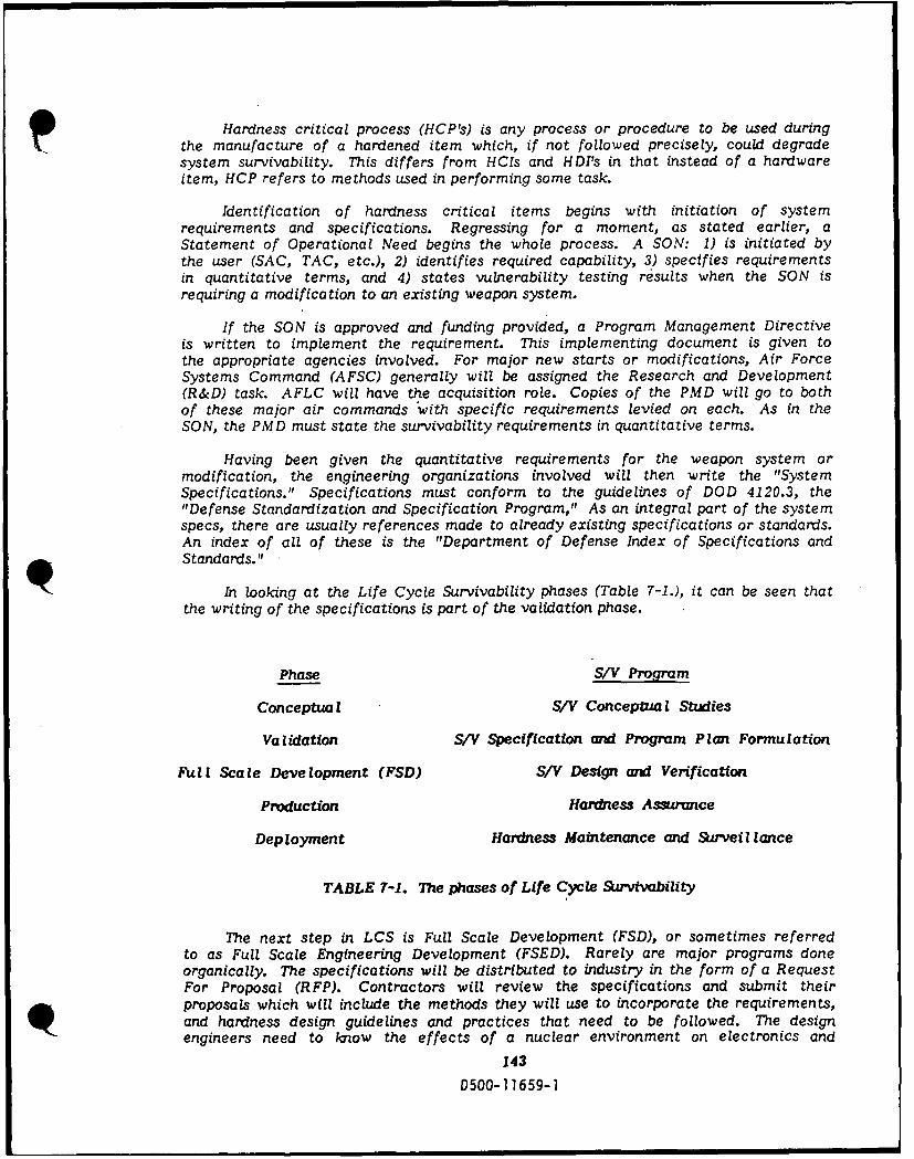
Hardness critical process (HCP's) is any process or procedure to be used duringpthe manufacture of a hardened item which, if not followed precisely, could degradesystem survivability. This differs from HCIs and HDI's in that instead of a hardwareitem, HCP refers to methods used in performing some task.
Identification of hardness critical items begins with initiation of systemrequirements and specifications. Regressing for a moment, as stated earlier, aStatement of Operational Need begins the whole process. A SON: 1) is initiated bythe user (SAC, TAC, etc.), 2) identifies required capability, 3) specifies requirementsin quantitative terms, and 4) states vulnerability testing results when the SON isrequiring a modification to an existing weapon system.
If the SON is approved and funding provided, a Program Management Directiveis written to implement the requirement. This implementing document is given tothe appropriate agencies involved. For major new starts or modifications, Air ForceSystems Command (AFSC) generally will be assigned the Research and Development(R&D) task. AFLC will have the acquisition role. Copies of the PMD will go to bothof these major air commands "with specific requirements levied on each. As in theSON, the PMD must state the survivability requirements in quantitative terms.
Having been given the quantitative requirements for the weapon system ormodification, the engineering organizations involved will then write the "SystemSpecifications." Specifications must conform to the guidelines of DOD 4120.3, the"Defense Standardization and Specification Program," As an integral part of the systemspecs, there are usually references made to already existing specifications or standards.An index of all of these is the "Department of Defense Index of Specifications andStandards."
In looking at the Life Cycle Survivability phases (Table 7-1.), it can be seen thatthe writing of the specifications is part of the validation phase.
Phase S/V Program
Conceptua L S/V Conceptual Studies
Validation S/V Specification and Program Plan Formulation
Full Scale Development (FSD) S/V Design and Verification
Production Hardness Assurance
Deployment Hardness Maintenance and Surveillance
TABLE 7-1. The phases of Life Cycle Survivability
The next step in LCS is Full Scale Development (FSD), or sometimes referredto as Full Scale Engineering Development (FSED). Rarely are major programs doneorganically. The specifications will be distributed to industry in the form of a RequestFor Proposal (RFP). Contractors will review the specifications and submit theirproposals which will include the methods they will use to incorporate the requirements,and hardness design guidelines and practices that need to be followed. The designengineers need to know the effects of a nuclear environment on electronics and
143
0500-11659-1

materials. They must also understand the function of the system or circuit to answerthe questions: 1) must the system/circuit operate during the nuclear event?, 2) 1.:illthe system/circuit be temporarily upset during the nuclear events?, and 3) how fastwill the system recover to normal operation after an upset?
Hardness design practices which need to be considered include:
EMP/SGEMP DESIGN PRACTICES
0 MINIMIZATION OF ELECTROMAGNETIC PICKUP
0 SHIELDING AND GROUNDING TECHNOLOGY
0 PACKAGE SHIELDING METHODS
0 CABLE SHIELDING METHODS
0 GROUNDING METHODS
0 TRANSIENT SUPPRESSION
0 CIRCUIT DESIGN
RADIATION DESIGN PRACTICES
0 PART SELECTION
0 PHOTOCURRENT LIMITING
0 DERATING PARAMETERS PRIOR TO DESIGN
0 CIRCUIT CONFIGURATIONS
MECHANICAL DESIGN PRACTICES
0 MATERIAL SELECTION
0 EQUIPMENT LOCATION
0 POSITIONING OF COMPONENTS ON CARDS
0 SHOCK ISOLATION
0 PROTECTION AGAINST DUST PARTICLES
Quite often, a flight test program will be an integral part of an R&D effort.Even with no actual flights, some form of testing must be done prior to acceptanceof a new weapon system or modification. The reference for testing is AF Regulation80-14, "Research and Development Test and Evaluation."
144
D500-11659-1

During the concept phase, all analyses done regarding hardness are recordedin a series of documents called the "Hardness Assurance Design Documentation" (HADD).As the design work and development progress, all data pertaining to the nuclear hardnessis incorporated in the HADD. As the weapon system goes into the acquisition phase,the HADD accompanies the hardware and is the basic document (s) for hardnessmanagement of the weapon system. Hardness Assurance (HA) is defined as: "proceduresapplied during the production and deployment phase to ensure the end product is inaccordance with the hardness design specifications or requirements." The HADDcontains an HCI listing, HCI design criteria, Vulnerability Analysis Reports (VAR)on each mission essential system, a Hardness Assurance Plan, and an HM/HS ProgramPlan. The HM/HS Program Plan is more or less a summary of the entire HADD.Elements of the HM/HS Program Plan are: background, hardening approach,organizational responsibilities, parts control, configuration control,repair/reprocure ment, maintenance plan, and surveillance plan.
HCI/HCP SYMBOLS
Identification of HCIs and HCP's is necessary for configuration control and toflag potential degradations in hardness if proper hardness maintenance techniquesare not followed. DOD-STD-100C, "Engineering Drawing Practices," has a requirementthat the following statement be placed on engineering drawings having HCIs or HCP's.
"This drawing depicts Hardness Critical Items (HCI) orHardness Critical Processes (HCP). All changes to or proposedsubstitutions of HCIs or HCP's must be evaluated for hardnessimpacts by the engineering activity responsible forsurvivability."
Technical Orders must also be flagged so that maintenance personnel are madeaware that their maintenance actions could have an impact on nuclear hardness.
Drawings and technical orders will be labeled by having the letters "HCI" or "HCP"enclosed in a box, as shown in Figure 7-3.
HCI
HCPFIGURE 7-3. HCI/HCP Markings.
Engineering drawings and technical orderswill have HCPs and HCP's flagged with these symbols.
Figure 7-4 is an illustration taken from a tech order page which describes the"HCP" flag and how it is used. Figure 7-5 is a sample from a tech order showing theHCP markings in an actual maintenance procedure.
145
D500-11659-I
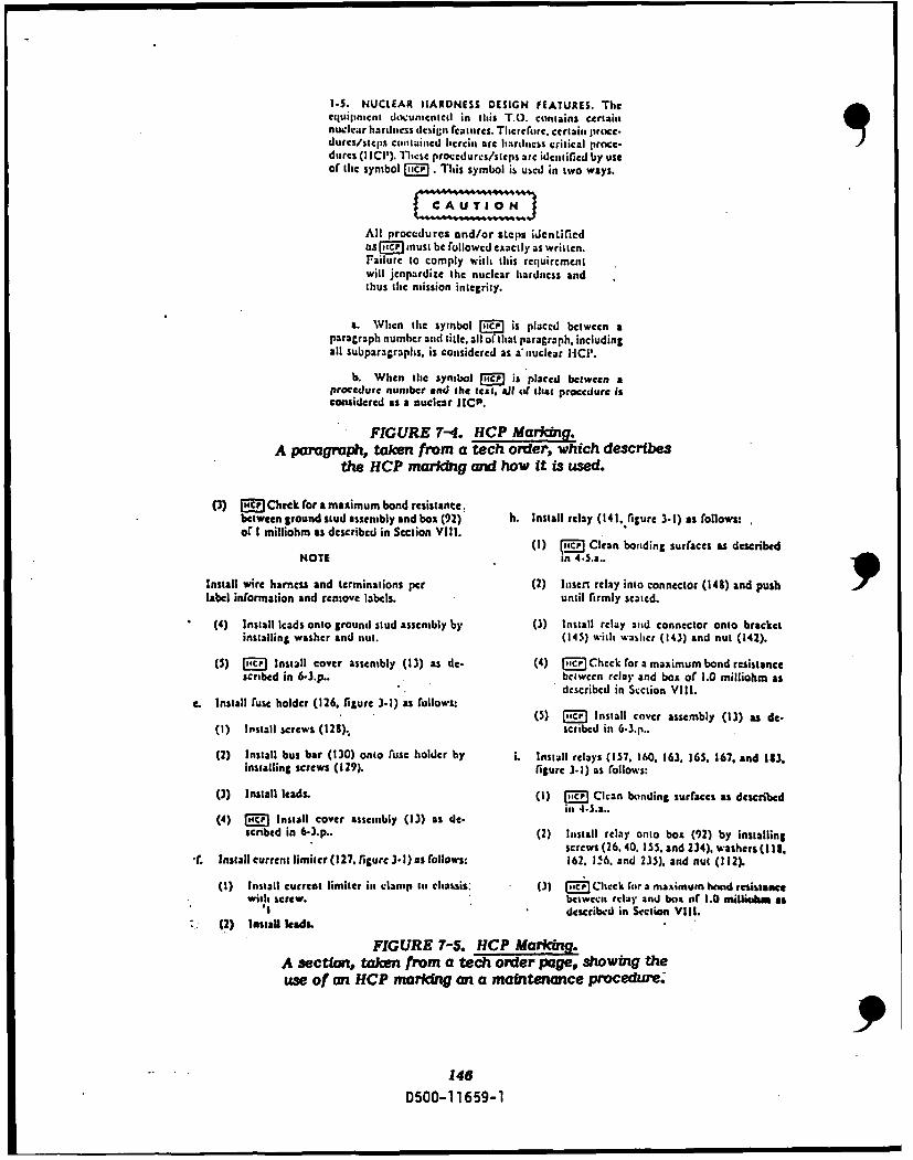
M.. NUCLEAR HIARDNESS DESIGN FEATURES. Theequsinment docinitl in Imes T.(). contains certaindurcs/stcgis cntained licrcin are hardness critical prncc.
durcs (1 I01). I'licse procedfurcs/steps arc identfired by useof tire symbol mmv.This symbol is used in two ways.
All proce~dures and/or steps identifiedus Micr must be followed exactly as written.Failure to comply wetl this requiecmentwill jeopairdize the nuclear hardness andthus tire mission integrity.
a. Whlen the symbol MR is placed between aparagraph number and title, all of that paragraph, includingall subparagraphs, is considered as aLouclear I-IC'.
b. When tire symbol Mg~ is placed between aprocedure nunmber and the teat. aJll# m(dist procedure isconsidered as a nuclear id'P.
FIGURE 7-4. HCP Marking.A paragraPh, taken from a tech order, which describes
the HCP markig and how it is used.
(3) Muc, Check for a maximum bond resistance,between ground stud assembly and box (92) h. Install relay (141..igure 3.1) as (allows:of I milliohm as described in Section Vill. () M C a odn ufcsa ecie
NOTE in 4.5.a..
Install wire harness and terminations per (2) hisen relay into connector (148) and push9label informsation and rentove labels. until firmly seated.
(4) Install leads onto ground stud assembly by (3) Install relay and connector onto bracketinstalling washer and nut. (145) with washer (143) and nut (142).
(5) MC Install cover assembly (13) as de- (4) mIC Chcck ror A maximum bond resistancescribed in 6-J.p- bctween relay and boa or 1.0 milliahms as
described in Scction Vill.c. Install ruse holder (126. .figure .3.1) as rollows:(5 iO nsalcvrsemy(1)sd.
(I) Install screws (128).. .scribed in 6 -3.p..
(2) Install bus bar (130) onto ruse holder by L. install relays (157. 160. 163. 165. 167. and 1113.installing screws (129). figure 3.1) as rolows;
(3) Install leads. (I) [cr Clean bonding surface& as describedin 4-5.a..
(4) "c,' Install cover assembly (13) as ale.seribed in 6-3-.. (2) Install relay onto box (92) by installing
screws (26. 40, 15 '5. and 234), washers (I 18.SInstall current limiter (127. figure 3-.1) as follows: 162. I 6. and 235). and nut (112).
(1) Install current limiter is, clamp to chassis, (3) Mc Check foir a msaximum bond resistanewith screw. betweCas rMay and baa uOf 1.0 MilliblhM11 as
* describcd in Section Vill.(2) Install leads.
FIGURE 7-5. HCP Marking.A section, taken from a tech order page, showing theuse of an HCP marking an a matntenance procedure.
146D500-1 1659-1
CONFIGURATION MANAGEMENT
Configuration management involves configuration identification and configurationcontrol. The first order of business is to provide some definitions. Following thedefinitions will be an explanation of the Air Force's configuration management approach.
Definitions (per MIL-STD-480, "Configuration Control")
ConfigurationThe functional and/or physical characteristics of hardware or software asset forth in technical documentation and achieved in a product.
Configuration Item (CI)An aggregation of hardware/software, or any of its discrete portions whichsatisfies an end use function and is designated by the Government forconfiguration management.
Configuration IdentificationThe current approved or conditionally approved technical documentationfor a configuration item as set forth in specifications, drawings and associatedlists and documents referenced therein.
Configuration ControlThe systematic evaluation, coordination, approval, or disapproval, andimplementation of all approved changes in the configuration of a CI afterformal establishment of its configuration identification.
Configuration ManagementA discipline applying technical and administrative direction and surveillanceto (1) identify and document the functional and physical characteristicsof a configuration item, (2) control changes to those characteristics, and(3) record and report change processing and implementation status.
Critical ItemAn item within a configuration item which, because of special engineeringor logistic considerations, requires an approved specification to establishtechnical or inventory control at the component level.
Engineering ChangeAn alteration in the configuration of a configuration item or item delivered,to be delivered, or under development after formal establishment of itsconfiguration identification.
Engineering Change ProposalA term which includes both a proposed engineering change and thedocumentation by which the change is described and suggested.
Form, Fit and FunctionThat configuration comprising the physical and functional characteristicsof the item as an entity but not including any characteristics of the elementsmaking up the item.
Base LineA configuration identification document or a set of such documents formallydesignated and fixed at a specific time during a Cl's life cycle. Base lines,plus approved changes from those base lines, constitute the currentconfiguration identification.
147D500-1 1659-1

In accordance with AFR 65-3, "Configuration Management," all echelons of theMilitary Services and Defense Agencies and DOD Industry interfaces shall exerciseconfiguration control.
After a baseline has been established, any change to a configuration item (CI)must take into consideration, the life cycle of that CI. Any proposed change to a CIwill be evaluated by all affected activities, such as engineering, logistic support,production, quality assurance, reliability, maintenance, procurement, and operations.
Engineering changes to the configuration of a CI need to conform to one or moreof the following:
Change or changes will:
a. Correct deficiencies.b. Satisfy change in operational or logistics support requirements.c. Effect substantial life cycle cost savings.d. Prevent or allow desired slippage in an approved schedule.
A recommended change will be in the form of an Engineering Change Proposal(ECP) prepared and submitted in accordance with MIL-STD-480 or MIL-STD-481. TheECP will be evaluated by a Configuration Cohtrol Board (CCB). The CCB membershipwill consist of representatives from all affected organizations and those members willtake approval/disapproval and implementation (if approved) steps required.
HCIs, a subset of configuration items, having an ECP against them, must beevaluated closely to determine whether or not the nuclear hardness is degraded as aresult of the proposed change. In some cases, a change in the mission of a weapon systemmay result in a reduction in the hardness requirements. The changes which must beguarded against are those that inadvertently lead to a hardness degradation.
For a more detailed explanation of configuration management and the evaluationof ECPs, review AFR 65-3, "Configuration Management," MIL-STD-480, "ConfigurationControl," and MIL-STD-483, "Configuration Management Practices for SystemsEquipment, Munitions, and Computer Software."
148
0500-11659-1

SECTION 8HAR DNESS MAINTENANCE/HARDNESS SURVEILLANCE
"HARDNESS.
NA MEASURE OF A SYSTEM'S ABILITY TO WITHSTAND EXPOSURETO ONE OR MORE EFFECTS OF NUCLEAR WEAPONS."
Per AFR 80-38, Hardness Maintenance (HM) consists of "procedures applied duringthe operational phase to make sure that the system's operation, logistics support, andmaintenance do not degrade the system's designed and fielded hardness." One of theprimary difficulties in applying these "procedures", is that hardness does not readilyfall into the traditional "form-fit-function" concept of maintaining a weapon system.Much of the equipment used in systems currently being built or modified, plays a dualrole; one, to perform some specific function as a factor in the every day operationalrequirements, and two, provide for a shield against the threats of a nuclear environment.In the past, if a new part would fit where the original part fit, looked the same as theold part, and performed the same operational functions, it could be used as as suitablereplacement. With nuclear hardening, the need has come for a closer look at the methodsemployed in the selection of substitute parts, such that a hardness criteria is includedwith the form-fit function requirement.
Another maintenance problem created with the inclusion of hardness is that oftesting. Testing of a non-hardened system is typically accomplished by performingan operational check-out of functional requirements. Under normal circumstances,routine maintenance does not include testing of the level of hardness. How then, canthere be any assurance that there has been no degradation in a system's hardness?
The first step is through the Hardness Surveillance Program. Hardness Surveillance(HS) is defined by AFR 80-38 as: "Scheduled tests and inspections performed duringthe operational phase to ensure the system's designed hardness is not degraded throughoperational use, logistics support, maintenance actions, or natural causes." HS is requiredfor detection of system hardness degradation because the hardness design features arenot exercised or monitored during normal system operation.
By performing surveillance on the hardness condition of a system, an 'on the spot'determination can be made and recorded in a log as to the amount of degradationsexperienced on the particular sample being evaluated. Additionally, with the properdocumentation and record keeping, the results of surveillance testing can be accumulatedinto a data base to provide guidance in establishing periodic inspection schedules, basedon predicted failure rates.
The success of a Hardness Maintenance/Hardness Surveillance plan is dependentupon making conscientious efforts to familiarize oneself with all aspects of the LifeCycle Survivability concept. The particular job of an engineer in the HM/HS organizationis very specialized. It certainly does not require that you "work" all requirements ofa total program. However, it is advantageous to to be aware of the many supportorganizations and the "tools" available which will smooth the accomplishment of thisengineering job. Some of the "tools"
149 "
D500-11659-1

are: 1) the Air Force Technical Order System, 2) specifications, 3) standards, 4) AirForce Regulations, and 5) the Maintenance Data Collection System. Each of thesetools is managed and controlled by an organization or organizations having experts onthe use of the tools. It is not necessary to become the expert in all aspects of a programbut awareness of the different areas.involved is needed to enlist the aid of those experts.
The following pages provide an introduction to some of the aforementioned"systems." It is not all inclusive but should direct the engineer in pursuit of additionalknowledge.
-----------_ JL.%&.
V..1.
AF
TECHNICAL ORDER
SYSTEM-AFR 8-2 levies a requirement for all systems and equipment to be maintained
in accordance with Technical Orders (T.O.'s). Due to the large numbers of technicalorders which are needed to support this requirement, a T.O. management system wasestablished for the purpose of numbering, tracing, and controlling the T.O.s. As withany complex system, it might appear that the tech order system is difficult to use.However, armed with a few basic facts, you should be able to use the system with fewdifficulties.
There are. two very general categories of tech orders; those which provideinformation and instructions for operating, installing, maintaining, inspecting, ormodifying system and equipment items, and those which specify policy, procedures,and use of all T.O.s.
The Air Force Technical Order system is dk -cribed in T.O. 00-5-1. In this T.O.,you will find the purpose and concept of the tech order system, a description of thevarious types of tech orders, procedures for tech order development, and explanationof the tech order numbering system, procedures for recommending T.O. improvementsor corrections, and other policies/procedures for the T.O. system. As engineers onAir Force weapon systems, it is important to be familiar with T.O. 00-5-1, and the T.O.system.
10
0500-11659-1
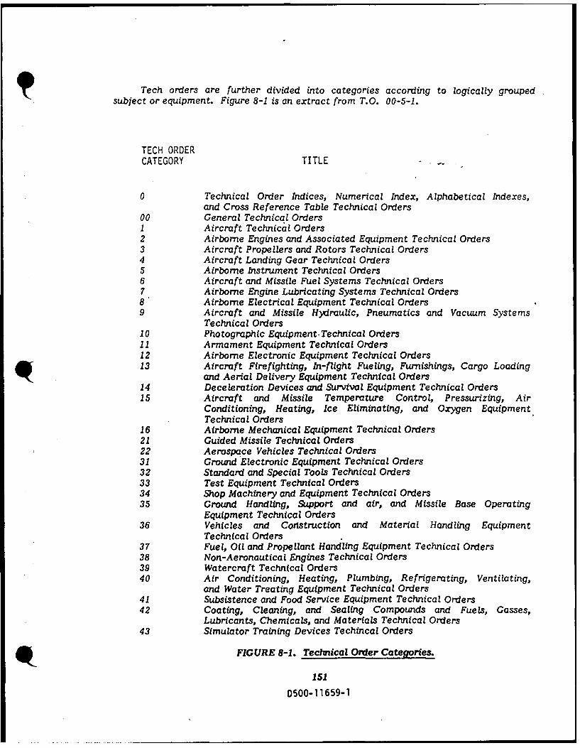
Tech orders are further divided into categories according to logically groupedsubject or equipment. Figure 8-1 is an extract from T.O. 00-5-1.
TECH ORDERCATEGORY TITLE
0 Technical Order Indices, Numerical Index, Alphabetical Indexes,and Cross Reference Table Technical Orders
00 General Technical Orders1 Aircraft Technical Orders2 Airborne Engines and Associated Equipment Technical Orders3 Aircraft Propellers and Rotors Technical Orders4 Aircraft Landing Gear Technical Orders5 Airborne Instrument Technical Orders6 Aircraft and Missile Fuel Systems Technical Orders7 Airborne Engine Lubricating Systems Technical Orders8 Airborne Electrical Equipment Technical Orders9 Aircraft and Missile Hydraulic, Pneumatics and Vacuum Systems
Technical Orders10 Photographic Equipment.Technical Orders11 Armament Equipment Technical Orders12 Airborne Electronic Equipment Technical Orders13 Aircraft Firefighting, In-flight Fueling, Furnishings, Cargo Loading
and Aerial Delivery Equipment Technical Orders14 Deceleration Devices and Survival Equipment Technical Orders15 Aircraft and Missile Temperature Control, Pressurizing, Air
Conditioning, Heating, Ice Eliminating, and Oxygen EquipmentTechnical Orders
16 Airborne Mechanical Equipment Technical Orders21 Guided Missile Technical Orders22 Aerospace Vehicles Technical Orders31 Ground Electronic Equipment Technical Orders32 Standard and Special Tools Technical Orders33 Test Equipment Technical Orders34 Shop Machinery and Equipment Technical Orders35 Ground Handling, Support and air, and Missile Base Operating
Equipment Technical Orders36 Vehicles and Cortstruction and Material Handling Equipment
Technical Orders37 Fuel, Oil and Propellant Handling Equipment Technical Orders38 Non-Aeronautical Engines Technical Orders39 Watercraft Technical Orders40 Air Conditioning, Heating, Plumbing, Refrigerating, Ventilating,
and Water Treating Equipment Technical Orders41 Subsistence and Food Service Equipment Technical Orders42 Coating, Cleaning, and Sealing Compounds and Fuels, Gasses,
Lubricants, Chemicals, and Materials Technical Orders43 Simulator Training Devices Techincal Orders
FIGURE 8-1. Technical Order Categories.
151
D500-11659-1

TECH ORDERCATEGORY TITLE
44 Common Hardware Equipment Technical Orders45 Railroad Equipment Technical Orders46 Office, Duplicating, Printing and Binding Equipment Technical
Orders47 Agriculture Equipment Technical Orders49 Optical Instruments, Timekeeping,. and Navigational Equipment
Technical Orders50 Special Service Equipment Technical Orders51 Automatic Test System Technical Orders60 Explosive Ordinance Disposal Technical Orders
FIGURE 8-1. (continued)
The least effective method for locating the appropriate T.O. for the task at handis to go to the T.O. library and start scanning the shelves. That would be closelyequivalent to searching for a particular book in a public library by merely walking upand down the aisles except that finding the T.O. would probably be more difficult.In the T.O. library, typically all that is exposed to view in passing is the T.O. number;no title, no distinguishing size; color, etc.
Even when very little information is available concerning the T.O. -needed, thereare systematic approaches to be taken. T.O. 0-1-01 is the "Index of Indexes." In thisT.O., a listing of other indexes appears according to the category breakdown as shownin Table 8-1. By knowing the type equipment for which a tech order is needed, a categorycan be selected which most closely describes the equipment. Occasionally however,a piece of equipment might fit more than one category and may require a little extrainvestigation. Having located the index by category, that index can then be scannedfor the T.O. number for the applicable volume.
T.O. 0-1-01
NUMERICAL INDEX
ALPHABETICAL INDEX
CROSS-REFERENCE TABLE
TABLE 8-1. List of Indexe3 for T.O.'&
If either the part number )r the National Stock Number (NSN) for the equipmentis known, the task of locating the correct T.O. becomes a matter of simply lookingthat number up on micro-fiche available in the T.O. library and with that number, willbe listed all T.O.s having pertinence.
152D500-1 1659-1

TECH ORDER TYPES
There are five types of technical orders: 1) "Methods and Procedures," 2) "TechnicalManuals," 3)"Abbreviated Technical Orders," 4) "Index," and 5) "Time Compliance TechOrders" (TCTOs). Figure 8-2 shows a diagram of the five types as well as examplesfor each of the five. Preliminary Tech Orders (PTOs) are under the Air Force T.O.system, but do not fit into any of the "type" classifications. PTOs are used on a newweapon system or a modification as a means of doing the validation and verificationof the equipment and also the tech order data. After the equipment has been acceptedand the pertinent corrections made to the technical data, PTOs are published in thefinal versions which will fit into one of the five types.
AIR FORCE
TECHNICAL ORDER SYSTEM
TECHNI MATHODS AND PROCEDURES ABBREVIATED
TECHNi 'ORDERS TECHNICAL ORDERS
TIME COMPLIANCE [ INDEX TYPE 1TECHNICAL ORDERS TECHNICAL ORDERS INSPECTION WORK CARDS
AND WORKSHEETS
LUBRICATION CHARTS
AIRCRAFT AF TECHNICAL ORDER SYSTEM~CHECKLISTS
MISSILES DI TRIOUTION AND STORAGE
OF AF TECHNICAL ORDERCE SYSTEM PUBLICATIONS PRELIMINARY TO% ARE NOT CONSID.
ERED A TYPE OF TO. BUT ARE PREPAREDSPECIAL WEAPONS VISUAL INSPECTION SYSTEM IN LIMITED OTY TO TEST AND VERIFY
THE PROCEDURES CONTAINED THEREIN
OTHER EQUIPMENT HI.VALUE ITEM LISTS THEY ARE NOT NORMALLY USED FOROPERATION AND MAINTENANCE UN.
JOB GUIDE MANUALS (OTHER) LESS THEY HAVE BEEN VERIFIED ANDAPPROVED BY HQ MAJOR COMMAND.
COMMERCIAL TYPE AFSC. AFLC.PUBLICATIONS
IMMEDIATE ACTION TO INDEXES
URGENT ACTION, _ _ALPHARETICAL
ROUTINE ACTIONCROSS REFERENCE TABLES
RECORDLIST OF APPLICABLE
INTERIM PUBLICATIONS (LOAP)
FIGURE 8-2. Types of Technical Orders.
153D500-11659-1

MAINTENANCE DATA COLLECTION SYSTEM
One of the most important segments of a good Hardness Maintenance/HardnessSurveillance program is accurate documentation of maintenance actions. TheMaintenance Data Collection System (MDC System) provides for a documented historyof all maintenance actions, both on and off equipment. T.O. 00-20-2 is the MDC Systemtech order, and it states that the objectives of the MDC Systems are:
a. Collecting base level maintenance production data.b. Storing base level maintenance production data.c. Retrievintg base level maintenance production data.
FIGURE 8-3. Maintenance Data Collection System.
Rules and procedures governing the operations of the MDC System are found inthe 00-20-2-XX series of tech orders, AFM 66-267, AFM 66-278, AFM 171-267,AFM 1 71-278, and AFM 1 71-114.
The collection process involves documenting all maintenance actions on an AFTOForm 349 (see Figure 8-4) and processing that data into a computer data base.
154
D500-11659-1
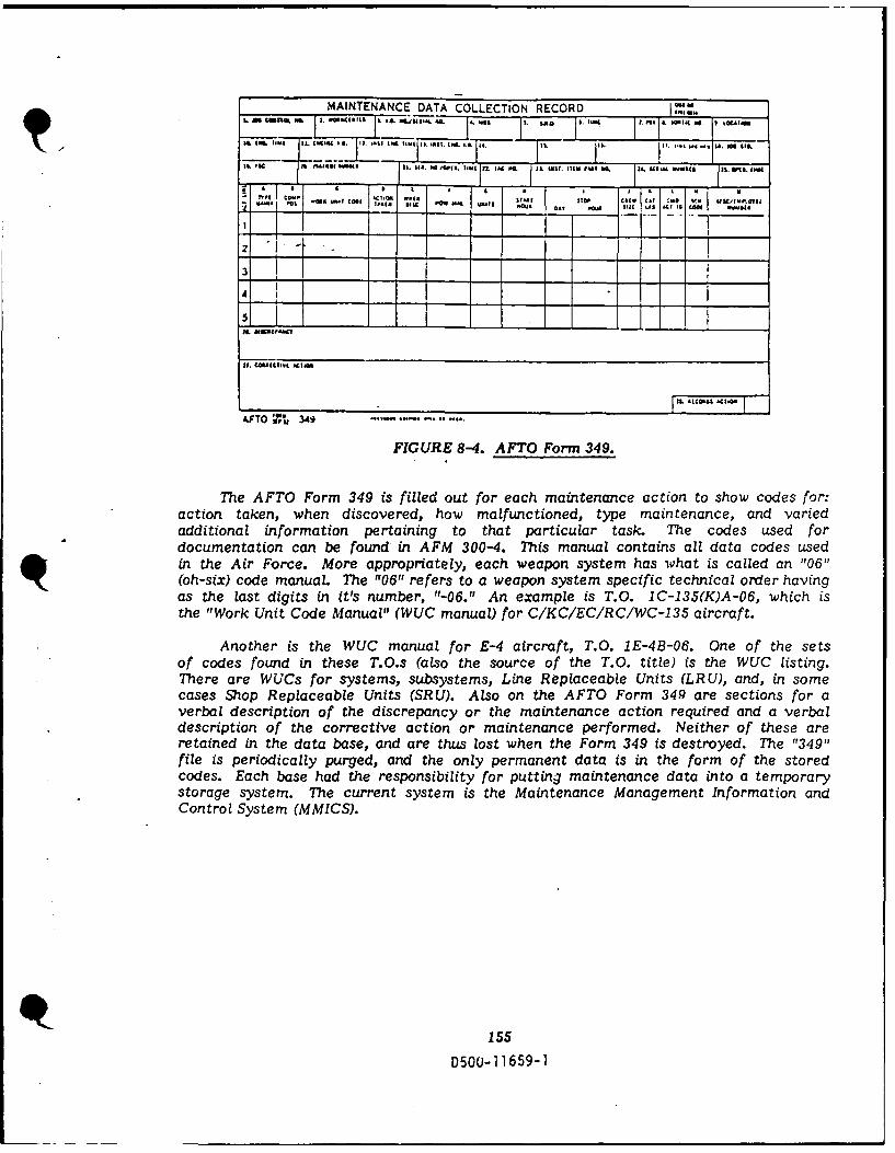
MAINTENANCE DATA COLLECTION RECORD. 0 4 2 . U . . 01 L..... 14. .A 108,
ILI/2.0 IL 180102i I I. I1 11 £11 01 IM I). Il$|l. |1L I.mL .g. IL II. i*., ,.c i. 1
IL so jjf1 rru0a.. 08042 IS. 14.. IA Wi . 11. Z 1. Ad, . .IL WIS. Il11 14 34. .11 " I -
in Ic ...b~ . *I
3I I
I,. 11081l1l l
AFTO , A 349
FIGURE 8-4. AFTO Form 349.
The AFTO Form 349 is filled out for each maintenance action to show codes for:action taken, when discovered, how malfunctioned, type maintenance, and variedadditional information pertaining to that particular task. The codes used fordocumentation can be found in AFM 300-4. This manual contains all data codes usedin the Air Force. More appropriately, each weapon system has what is called an "06"(oh-six) code manual The "06" refers to a weapon system specific technical order havingas the last digits in it's number, "-06." An example is T.O. IC-135(K)A-06, which isthe "Work Unit Code Manual" (WUC manual) for C/KC/EC/RC/WC-135 aircraft.
Another is the WUC manual for E-4 aircraft, T.O. 1E-4B-06. One of the setsof codes found in these T.O.s (also the source of the T.O. title) is the WUC listing.There are WUCs for systems, subsystems, Line Replaceable Units (LRU), and, in somecases Shop Replaceable Units (SRU). Also on the AFTO Form 349 are sections for averbal description of the discrepancy or the maintenance action required and a verbaldescription of the corrective action or maintenance performed. Neither of these areretained in the data base, and are thus lost when the Form 349 is destroyed. The "349"file is periodically purged, and the only permanent data is in the form of the storedcodes. Each base had the responsibility for putting maintenance data into a temporarystorage system. The current system is the Maintenance Management Information andControl System (MMICS).
155D5O0-11659-1
IA ICI3slIa
TECHNICAL MANUAL
AIRCRAFT MAINTENANCE
WORK UNIT CODE MANUAL
USAF SERIESCIC/[CIRCIWC-I1S
AIRCRAFT
Im MI H~ltqi meee I S
, Pss nS. . SM .
- IS I - I AWIll
FIU t 8M Wok Ui C M u
a~s * PU'sS
PCC 5 fe l U PSe r
aw. I .II -I SUIIMII I1
1. I PIS.II Ill
FIGURE 8-5. Work Unit Code Manual
(Title page of the -135 Series Aircraft WUC ManuaL)
The storage process involves gathering all base level maintenance data and storingit in a centrally located, permanent data base. The system for permanent storage isthe DO-56, Product Performance System. It is located at OC-ALC, and managed byMMMMB. The DO-56 system is not a real time system, and will therefore have a certainamount of lag time between the time a maintenance action is performed, and the timethat the data is available for retrieval. Transfer of data from MMICS to DO-56 isnormally accomplished once every 30 days.
Retrieval of maintenance data from the DO-56 can be a benefit to LCS in thatthe frequency of maintenance actions can be monitored, high maintenance (or lowreliability) items ,ill be visible, and inspections (frequency and results) can be tracked,etc. Data is coded by fields and the retrieval process allows for "calling up" all datahaving specified codes in specified fields. There are currently no codes which isolatehardness peculiar problems/maintenance. Efforts are on-going to investigate andrecommend modifications to the current DO-56 to allow pinpointing maintenance actionsdue specifically to nuclear hardness deficiencies. OC-ALCIMMEAP is the "product"manager for the output of DO-56 system.
STANDARDIZATION
Standardization is the act of bringing something into conformity with a standard.A standard is defined as, "something set up and established by authority as a rule forthe measure of quantity, weight, extent, value, or quality."
156
D500-11659-1

FIGURE 8-6. Standards provide a measurable guideline forthe development of hardware, software and documentation.
Standardization is not limited to the government. Examples of commonly knownstandards in industry are ANSI (American National Standards Institute), ASTM (AmericanSociety for Testing and Materials), and IEEE (The Institute of Electrical and ElectronicsEngineers). Within the government, there is certainly an abundance of guidance forstandardization. For anything you do, as a part of your job, you can almost be certainthat one of two possibilities exists: there is some form or standard to guide you, oryou are the first to do it.
The AF Tech Order System, which has already been discussed, is one form ofstandardization. Tech orders give step-by-step instructions for the performance ofa task, they give descriptions, by assigned part numbers and National Stock Numbers(NSNs), of the acceptable replacement parts which can be used in the repair of equipment,or they specify tolerance limit for items being inspected.
There are other media used to provide standards. One of them is called a "militarystandard." Another is called a "military specification." The Defense Standardizationand Specification Program is described in the document, Standardization Directory,(SD-1), published by the Department of Defense (DOD). Items in the Air Force inventoryare assigned unique identifying numbers called National Stock Numbers (NSN) consistingof 13 digits. The first four of those digits represent the Federal Supply Classification(FSC) or a grouping of items by a class. SD-1 distributes the responsibility forstandardization, by FSC, to various agencies within DOD. As an example, resistorsare in the "5905" FSC. The assigned activity responsible for standardization of thisFSC is the "Defense Electronics Supply Center" (DESC) in Dayton, Ohio. DESC hasthe responsibility for a large portion of the electronics components used by DOD. The
157
D500-1 1659-1

"Defense Nuclear Agency" (DNA) is another organization having standardizationresponsibilities.
Not all standardization requirements for a given FSC are handled solely by onegroup. In many instances, one ogranization will be prime with numberous other groupshaving secondary or support functions. All of these agencies, as well as their assignedrequirements, are listed in the Standardization Directory.
Standards typically are given designations such as MIL-STD-XXXX orDODSTD-XXXX where "XXXX" is a unique number to differentiate one document fromanother. MIL-STD-143B is one standard. This one is titled "Order of Precedence forthe Selection of Standards and Specifications." There is a standard, MIL-STD-12D,which governs the use of abbreviations on drawings and in specifications, standards,and technical documents. MIL-STD-490 is the standard for "Specification Practices."
Specifications are done similarly. Usually a specification will be designated"MIL-S-XXX, "again where "XXX" is a unique number. MIL-S-83490, "Specifications,Types and Forms, "describes the different types of specs according to Table 8-2.
Type A - System SpecificationType B - Development Specifications
Type B1 - Prime ItemType B2 - Critical ItemType B3 - Non-Complex ItemType B4 - Facility or ShipType B5 - Computer Program
Type C - Product SpecificationsType Cla - Prime Item FunctionType Clb - Prime Item FabricationType C2a - Critical Item FunctionType C2b - Critical Item FabricationType C3 - Non-Complex Item FabricationType C4 - Inventory ItemType CS - Computer Program
Type D - Process SpecificationType E - Material Specification
TABLE 8-2. Types of Specifications.
It is not at all uncommon for a Standard or a Specification to reference otherStandards or Specifications as part of the requirements. A System Specification onan electronic sub-system may reference a standard on aircraft wiring, one or moreon electronic components, another one on the format for documentation, and so on.
As with tech orders, Specifications and Standards are indexed. They can be foundin an alphabetical listing (Part I) see Figure 8-7.. and a numerical listing (Part II) ofthe "Department of Defense, Index of Specifications and Standards" (DODISS).
p158
D500-1 1659-1

DEPARTMENT OF DEFENSE
PART. I
ALPHABETICAL LISTING
1JULY. 1985-*
FIGURE 8-7. Ihdex of Specifications arid Stanldards.
DOD Manual 4120.3-M is another important document to follow in order to complywith standardization requirements. The title is "Standardization Policies, Procedures,and Instructions."
159D500-1 1659-1
SECTION 9TESTING
The Air Force has thousands of electronic solid state components. The complexityof the systems coupled with high maintenance cost are drivers toward EMI-EMC testingand repairing rather than replacing the item.
During the everyday operation of a hardened system, few failures of the EMPprotection devices would have an adverse effect on operation. If the EMP failure dideffect system operation, the effect would be "written up" and maintenance would acton the problem. Operational degrades or failures are covered bythe T.O.'s.
So why add an extra work load? Obviously, the answer is "To insure that theassigned mission can be accomplished, if an EMP event should occur."
If we are going to test aircraft or systems, then the testers that are used shouldhave outputs that resemble the EMP pulse, or, at least as a minimum, test frequenciesof concern to EMP.
As stated earlier in the text, the EMP has a double exponential form. It rises,peaks, and decays in an exponential manner. The rise time is around 10 nsec., pulsewidth of 1 u sec, and the amplitude is such that a voltage field of 50,000 V/m may befelt close to the earth's surface. (These are standard numbers, not classified and areused by many companies.) This type of pulse will produce a broadband of frequenciesat the system or devices we want to protect.
When an EM Pulse strikes an aircraft, it radiates down the airframe, setting upa field (+ to -, or - to +), similar to the way a wave travels down a transmission line.When it reaches the end of the aircraft, a reflected wave is transmitted back up theairframe, because the "transmission line" was not terminated in it's characteristic imped- 7,ance. This wave is out of phase and will cancel a portion of the forward traveling wave,thus forming a damped sine wave.
Presently, there are few EMP hardened systems which have Hardness Mainten-ance/Hardness Surveillance test procedures in T.O. format and as importantly, the equip-ment is not readily available to do the testing.
There are test facilities being used by the Air Force, which evaluate a completeairframe, or missile system. For example, Kirkland AFB has facilities, TRESTLE andthe Horizontally Polarized Dipole (HPD) or the Vertically Polarized Dipole (VPD). Themost prevelant use of the larger test facilities are to evaluate individual airframesor vehicles and apply the results to like airframes or vehicles.
Also, there are more portable types of equipment which allows testing in the shop,on the aircraft, or in a laboratory environment, such as; Time Domain Reflectometers,EM, Sniffers, and DITMCO to name a few. We will discuss more types further intothe text.
If EMP is to be protected against, then the test facilites (fixed or portable) shouldgenerate signals that resemble the EMP pulse. As previously stated, this pulse is broad-banded or consists of many frequencies. This can be seen graphically in Figure 9-1.The varied peak amplitudes, resonant frequencies, along with pulse decay time, compli-cate the identifying and application of impedance matching functions, thus making
160
D500-11659-1
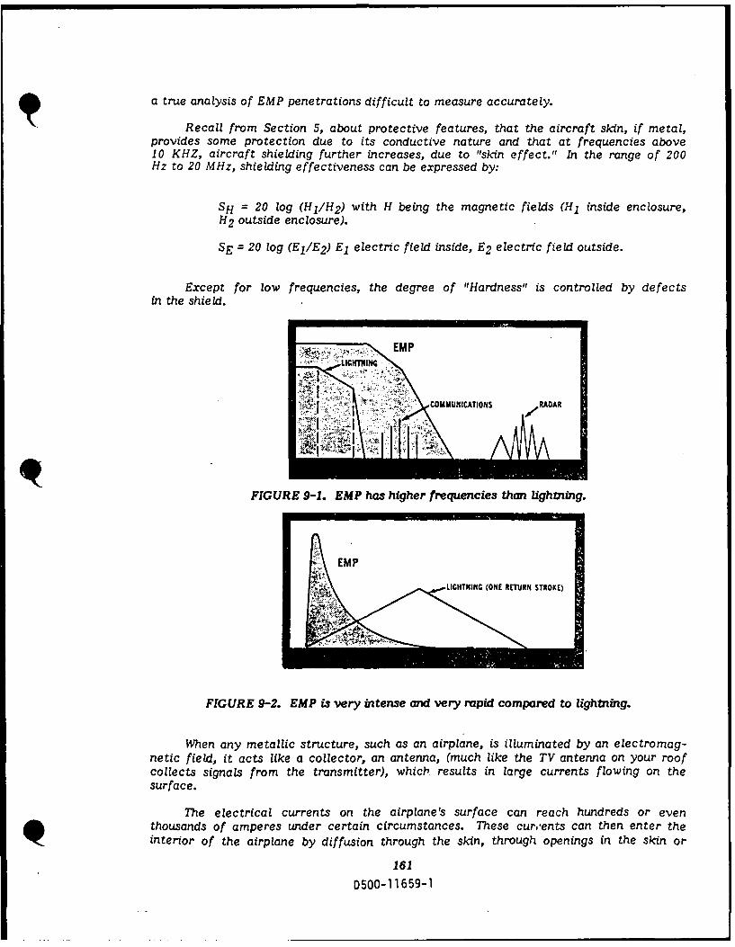
a true analysis of EMP penetrations difficult to measure accurately.
Recall from Section 5, about protective features, that the aircraft skin, if metal,provides some protection due to its conductive nature and that at frequencies above10 KHZ, aircraft shielding further increases, due to "skin effect." In the range of 200Hz to 20 MHz, shielding effectiveness can be expressed by:
SH = 20 log (H1 /H 2 ) with H being the magnetic fields (HI inside enclosure,H2 outside enclosure).
SE = 20 log (El/E2 ) El electric field inside, E2 electric field outside.
Except for low frequencies, the degree of "Hardness" is controlled by defectsin the shield.
~EMP
COMMUNICATIONS RAAR
FIGURE 9-1. EMP has higher frequencies than lightning.
EMP
LIGHTNING (ONE RURN STROKE)
FIGURE 9-2. EMP is very intense and very rapid compared to lightning.
When any metallic structure, such as an airplane, is illuminated by an electromag-netic field, it acts like a collector, an antenna, (much like the TV antenna on your roofcollects signals from the transmitter), which results in large currents flowing on thesurface.
The electrical currents on the airplane's surface can reach hundreds or eventhousands of amperes under certain circumstances. These curents can then enter theinterior of the airplane by diffusion through the skin, through openings in the skin or
161
D500-11659-1

by antennas. Fields from these sources will induce currents on the wire bundles andcables located nearby. On unshieded cables, the current is induced directly onto thewires; on shielded cables, the current is induced onto the shields and then coupled tothe wires at a reduced level. It is the current and voltage induced on the wires whichthen cause the system upsets or damage to components inside the electronic boxes orLR Us.
Hardness Verification testing will generally be done during the design and full-scaledevelopment stages. To a large extent analysis substitutes for testing this phase,particularly, when high frequency protection is the concern.
Hardness Assurance testing is performed in the production phase type of testing.i.e., to evaluate if the equipment will function as designed for its weapon system.
Hardness Surveillance and Hardness Maintenance are the two (2) categories oftesting that Air Force Logistic Command and their bases are most concerned with,as they impact the day to day deployment and storage of weapon systems.
EMP TESTING
Two major concerns of EMP Testing are that personnel at the base facilities arenot aware of the impact of EMP to their systems and secondly, EMP Testing is veryrarely built into the purchase contract. Hardness Surveillance is currently anafter-thought, but is a real concern to be addressed.
The EMP frequency range, as stated earlier, extends through the EMI range, andinto the 200 MHz range. Frequencies above 100 MHz are not considered a concern,due to the rapid attenuation of signals, without a matched transmission line. Wetherefore, limit testing to the range of frequencies from 100 MHz down to 100 KHz.
Types of testing which will be discussed, along with their advantages and disadvan-tages are:
DipoleMonopoleLog periodicParallel stripsDirect DeviceLoop transmitter (small & large)sniffercable testcontinuity checkingTPD
p162
D500-11659-1

TOTAL ILLUMINATION
The first type of testing to be covered will be total illumination. This is whenthe entire aircraft is exposed to a simulated EMP. The most talked about total illumina-tion test device is the TRESTLE. TRESTLE testing more closely resembles an in-flightenvironment. The incident field is somewhat different from a plane wave, and the woodenstructural members have a different dielectric constant than unity. The propagationnear the TRESTLE is not the same as free space, but the overall simulation is a fairapproximation of the free flight condition.
The TRESTLE test involves the use of a high power pulse network to bombarda system (KC-135R-M60 tank, etc.) with a near threat level damped sine wave pulse.Sensors are placed on the outside skin, fuselage, wing, antennas, etc. The purpose isto determine the power and frequencies that are felt at each part external to the testbody. For internal sensing, probes are positioned internal to the test body at entrypoints, breaks in the body (door, windows, bomb bays, wheel wells, etc.). Additionalinductive probes may be connected internally and externally to cables, wires, and coax,for LRUs. Sensors are also placed in air conditioning vents and conduit, inside and outsidefilters (mechanical and electronic) etc. The system under test has a hardness designfigure. As an example only, we will use a hardness margin of 30db. If an EMP eventcauses a signal to be felt at the skin of our aircraft, then through the aircraft skin inducedinto a cable, traveling down the cable to INS LRU pin D of plug P75201, the EMP signallevel must be a minimum of 30dB lower than the skin level signal.
> 30db = 20 log E outE in
The HPD and VPD are also total illumination tests, but do not get as close toa true inflight conductor as does the trestle. Signal ranges are from 3 KHz to 20 0Hz.The dipole provides a means to illuminate a complete airframe, or a black box. Thetest equipment is easily obtainable, and as different frequencies are used, antenna selec-tion is relatively easy.
The main disadvantage is susceptibility to reflections from surrounding objects.Daily atmospheric conditions also effect the wave front. Because of antenna selection,when shifting from frequency to frequency, the bandwidth is relatively narrow.
MONOPOLE
The wave impedance generated is greater than free space, lending a truer highimpedance incident field test. Both monopole and dipole wave impedance are easilycalculated from known formulas. As in the dipole, tests equipment is easy to obtain,and test set-ups are simple. The enclosure size is also greatly variable, and the testmay be internal or external to the system being tested.
Disadvantages are a non-uniform field, and their susceptibility to reflection andbandwidth are the same as in the dipole systems.
163D500-11659-1

DIRECT DRIVE INJECTION (DDD
This is one of the more commonly used methods of testing for EMP. DDI equipmentis compatible to the laboratory environment when subsystem boxes are being developed.It also works well in field testing. The test element is closely tied to the source andit is easier to deliver a more uniform and repeatable test pulse.
A damped sine or an oscillatory decaying pulse at the specified level is injectedinto a component by Direct Drive Injection and can be monitored by either a sensingwire inside a cable or an inductive sensor. The detected signal will be normally a dampedsine. The amount of protection provided by a protective device such as a zener diodeor a cable shield per meter length can be calculated in dB by:
.E out .P outdB= 20 log -or dBlO log Pin
The frequencies to be tested if a au , ed sine test is used should all be resonancefrequencies. These will be dependent on the impedence of the device under test foran aircraft, as well as length of the airframe or antenna. The aircraft resonancefrequency can be calculated using the following equation:
fres = 150 (1 + I
h 2 12
Where Ih" is the height of the aircraft, and "I" is it's length.
The other resonance frequencies for the components under test can be determinedfrom a network analyzer that provides impedance vs frequency.
LOG PERIODIC ANTENNAS (LPA)
The elements for generating an LPA test requires the Transmitter and Receiverto be log periodic. Gain of the LP is greater than a monopole of the same type, byapproximate 8db. The antenna is more broadband then the dipole or monopole antenna.
Disadvantages are that the physical size in the EMP ranges are impracticallylarge. The matching of the antenna to the system for an acceptable VSWR is hard toachieve.
PARALLEL STRIPS
Laying transmission and receiver strips parallel to the test item allows forgeneration and detection of the current induced on the surface of the test item. Theprimary test application would be to doors, hatches, windows, seamscables, etc.
Disadvantages are the difficulty in using and obtaining meaningful data in theEMP range 30 MHZ and above. Also, there is no way to account for reflective waveloss.
This type of testing is used by Hill AFB on the missile cables. 9164
D500-1 1659-1

In the case of missile cable repair for the minute man, ALCM and SRAM missiles,Hill AFB has prime responsibility. Their facility is unique in that cable troughs havebeen built which require each individual cable to be laid into its test bed. Testing ofthe cable assembly requires a computer and signal transmission/receiving equipment.The computer controls the power and frequencies to be transmitted into the trough.At the same time, a co-program is selecting the appropriate impedance matching forboth transmitter and receiver for the frequency being applied.
Each of the following frequencies covering the EMP bandwidth generated by aHigh Altitude Burst (HAB), 100 MHz, 75 MHz, 50 MHz, 25 MHz, I MHz and 100 KHz,are injected into the trough at different time intervals. The computer monitors thewires and the coaxial cables within the bundle. Missile cables are designed to give "X"protection against EMP. Any EMP signal felt at the surface of the cable, must be "X"dbdown at the inner conductor of the hardened cable. The computer program will monitorsurface voltage levels, and compare the inner conductor voltage level together. Then,by performing the mathematics, and with the aide of a comparator program, the computerwill make the determination of whether or not the shielding effectiveness is being met.
LARGE AND SMALL LOOP TRANSMITTING TO SELECTOR LOOP
Use of the large loop systems is to evaluate complete enclosures, and may beused in the 3 KHz to I MHz range. The small loop systems are effective in evaluatingdoor and hatches in the 100 HZ to 10 MHZ ranges.
Large loop advantages:
a. Total current at seams in one measurement.b. Uniformity of fields increase over small loop.c. Repeatability of tests are improved over small loops.
Small Loop Advantages
a. Large field strength can be obtained.b. Impedance of field may be calculated by common formulas.c. Shielding Effectiveness (SE) measurements obtainable at low impedance
fields.d. Minimize reflections, wall to wall.e. Placement of transmitter may be inside or outside enclosure.f. No special equipment required.
Large Loop Disadvantages:
a. Complex test set-ups.b. As the shape of the enclosure changes, test set-up must change.c. Frequency range is limited.
Small Loop Disadvantages:
a. Non-uniformity of fields.b. Difficult to test joints and seams with repeatability.c. Phase changes due to reflection effect shields.d. SE is not easily described from data.
165
D500-11659-1
SNIFFER TEST
This type of test is relatively simple. Set-ups are cheaper, and quicker to achievethan most other forms. Aids in identifying areas to be tested in more detail.
Disadvantages include:
a. Results are a relative scale in determining leakage. No S.E. qualitativeresults.
b. Credibility is not good.
SHIELDED CABLE TESTING
Recall from Section 5, under Coupling to Shielded Cables, the term called TransferImpedance. This transfer impedance is used to indicate how well the cable shield isworking. A test currently being studied by the Air Force is a method to check a shieldedcable while it is on the aircraft. This test not only checks the cable, but also the cqn-nectors at each end.
The test involves use of a network analyzer and inductive coupling probes. Oneprobe drives the shield, and the other probe measures the current. Then, the voltageon one of the inner wires is measured. The network analyzer sweeps the cable from5 Hz to 200 MHz and graphs the transfer impedance out on the screen or to the plotter.
Different types of degrading damage are supposed to produce different transferimpedance plots.
CONTINUITY TESTING
Continuity testing is mainly an operational check. It is very important to maintainsystem operation, and also necessary to maintain the hardness of the system. As strandsof wire break, they can become antennas. In addition, the VSWR of the cable may change,causing unwanted line reflections. DITMCO uses DC levels to test dielectric constants,and also checks continuity of the cable.
TERMINAL PROTECTION DEVICES (TPDs)
Terminal Protection Devices (TPDs), installed in S/V boxes can be easily testedon an individual basis. One such tester is the Joslyn 182 tester. This device pulsesthe individual circuits of an S/V box and tells the operator how good the TPDs are.It is currently under development and testing.
166
D500-11659-1

GLOSSARY
AIR BURST An atmospheric detonation of a nuclear weapon wherethe fireball does not reach the earth's surface.
ALPHA PARTICLE A spontaneously emitted particle from the nucleiof a radioactive element.
AMBIENT To surround on all sides.
ATOM The ultimate (or smallest) particle of an elementstill retaining the characteristics of that element.
ATOMIC BOMB A nuclear weapon utilizing fission energy only.
ATOMIC MASS The quantity of matter in a body, as measured inits relation to inertia. Mass is determined for a givenbody by dividing the weight of the body by the accelera-tion due to gravity.
ATOMIC NUMBER (See nucleus)
ATOMIC WEIGHT The relative mass of an atom of the given element.
BETA PARTICLE A spontaneously emitted charged particle from thenuclei of certain radioactive elements.
BLAST WAVE An air blast with sharply increased pressure at thefront edge, followed by strong, but transient winds,generated by an explosion.
BLAST YIELD The total energy that manifests itself as a shock(or blast) wave generated by a nuclear explosion.
CHAIN REACTION A series of nuclear reactions in which the productsof each reaction activate additional quantities ofthe reactants, thus causing new reactions. It canbe started by bombardment with alpha particles fromradium, etc.
CIRCUMVENTION The disconnecting of critical circuits during the radiat-ion pulse or for some fixed time measured from theinstant of radiation arrival
COMPTON CURRENT The generation of electron current as a result ofCompton processes.
COMPTON EFFECT The scattering of photons (gamma or x-rays) by theorbital electrons of atoms.
COMPTON ELECTRON The result of a Compton interaction with a p~hotoncreates an electron of increased energy ejectcd froman otom.
167
D500-11659-1

CONTAMINATION Following a nuclear or atomic explosion, the depositsof radioactive material on the surfaces of structures,areas, objects, or personnel. This material generallyconsists of fallout, in which fission products and otherweapon debris have become part of the particlesof dirt and etc.
COSMIC RAYS Rays at extremely short wave lengths and great pene-trating power, which bombard the earth from beyondits atmosphere.
CRITICAL MASS Under precisely specified conditions creating a mini-mum mass of a fissionable material that will justmaintain a fission chain reaction. The system mustbe supercritical for an explosion to occur.
CURIE A unit of radioactivity where the activity of a quantityof any radioactive species in which 3.700 x 10¹⁶ nucleardisintegrations occur per second.
DECAY, RADIOACTIVE The decrease in activity of any radioactive materialwith the passage of time, due to the spontaneousemission from the atomic nuclei of either alpha ofbeta particles, accompanied by gamma radiation.
DEPLETION REGION When p and n-type semiconductors are combined,the mobile charges around the junction in each sectionare attracted by the mobile charges across the junction.Since free electrons in the n-section have a higherenergy than the holes, the electrons drift across thejunction to fill the holes. This process neutralizesthe junction between the two sections. This neutralregion is called the depletion region.
DEUTERIUM The hydrogen isotope having an atomic weight ofapproximately 2 units. Combined with oxygen, itforms deuterium oxide, D2 0 (heavy water).
DISPLACEMENT A permanent effect is attributed to physical propertychanges or the irradiated material caused by energeticparticles (neutrons and secondary electrons).
DOPING Doping is the addition of impurity materials tosemiconductor substances. Doping alters the mannerin which such substances conduct currents. Thismakes the semiconductor, such as Germanium orSilicon, into an N-type or P-type substance.
DOSE A total quantity of ionizing or nuclear radiation.
DOSE RATE The amount of ionizing or nuclecr radiation whichan individual or material would receive per unit oftime, usually referred to or expressed as rads (orreins) per hour.
168
D500-1 1659-1
DOSIMETER An instrument for measuring and registering thetotal accumulated doses of ionizing radiations.
DYNAMIC PRESSURE The air pressure which results from the mass airflow behind the shock front of a blast wave.
ELASTIC SCATTERING The neutron strikes the nucleus in its ground state,then reappears without disrupting it.
ELECTROMAGNETIC PULSE Produced when an explosion occurs in an unsymmetricalenvironment by generating a sharp pulse of radiofrequency (long wavelength) electromagnetic radiation.This occurs especially at or near the earth's surfaceor at high altitudes.
ELECTRON A particle carrying a unit negative or positive chargeof very small mass.
ELECTRON VOLT (eV) The electron, when moved through a potential differ-ence of 1 volt, creates imparted energy. The equivalentis 1.6 x lu - 1 2 erg.
ELEMENT The basic variety of matter occurring in nature whichcompose substances of all kinds, either individuallyor in combination.
EMP (see electromagnetic pulse)
ENERGY The capacity for doing work and overcoming resistance.
ERG The unit of wc.rk or energy in the C.G.S. (metric)system, being the amount of work done by one dyneacting through a distance at one centimeter.
EXOATMOSPHERE "Outside, outer, outer part" - air surrounding theearth.
EXTRINSIC SEMICONDUCTOR An extrinsic semiconductor is a semiconductor towhich an impurity has been deliberately added. N-typeand P-type semiconductors are considered extrinsicsemiconductors.
FALLOUT The descent of particles, contaminated with radioactivematerial from the radioactive cloud, to the earth'ssurface. The contaminated particulate matter itselfis a term also used.
FIREBALL The result of the absorption by the surrounding mediumof the thermal x-rays emitted by the extremely hot(several tens of million degrees) weapon residuescreates a luminous sphere of hot 4 asses that forma few millionths of a second after a nuclear or atomicexplosion.
FISSILE One that can be split or easily cleft.
169
D500-11659-1

FISSION The process where by the nucleus of a particularheavy element, with the release of substantial amountsof energy, generally splits into two nuclei of lighterelements.
FISSION PRODUCTS A complex mixture of substances produced as a resultof nuclear fission.
FLUENCE The product of particle flux and time (units are parti-cles per square centimeter per second).
FLUX The product of particle density (particles per cubiccentimeter) and particle velocity (meters per second).
FORWARD BIAS In any diode or semiconductor junction, forward biasis a voltage applied so that current flows. EXAMPLE:For a diode, if negative voltage is applied to thecathode, and a positive voltage to the anode.
FREE AIR OVERPRESSURE The unreflected pressure, in excess of the ambientatmospheric presure, created in the air by the blastwave from an explosion.
FUSION With the release of substantial amounts of energy,the nuclei of light elements, especially those of the.isotopes of hydrogen, combine to form the nucleusof a heavier element.
GAMMA RAYS Electromagnetic radiations of high photon energyoriginating in atomic nuclei and accompanying manynuclear reactions.
GEIGER COUNTER An instrument for detecting and counting ionizingparticles that pass through it.
GROUND ZERO The point vertically above or below the center ofa burst, or a nuclear or atomic weapon, on the surfaceof land.
HALF LIFE The time required for the activity of a given radio-active species to decrease to half of its initial value,due to radioactive decay.
HARDNESS The state or quality of being hard in various senses,specifically radiation or EMP.
HARDNESS CRITICAL ITEM A piece of hardware which is both mission criticaland is essential to maintaining system survivability.
HARDNESS CRITICAL PROCESS Processes, specifications, and procedures which arehardness critical and which, if changed, could degradenuclear hardness.
HARDNESS DEDICATED ITEMS Items having no function beyond nuclear environmentdefense. They are also Hardness Critical Items.
170D500-11659-1

HEAVY HYDROGEN (See Deuterium)
HEAVY WATER A compound. like water, composed of oxygen andthe isotope of hydrogen, with the atomic weight oftwo.
HIGH-ALTITUDE BURST A detonation at an altitude of over 100,000 feet.
HYDROGEN BOMB A nuclear weapon in which the explosive energy isobtained from both nuclear fusion and nuclear fissionreactions.
INELASTIC SCATTERING This process is identical to elastic scattering, withthe exception of, the nucleus is left in an excitedstate.
INFRARED Electromagnetic radiations of wave lengths betweenthe longest red (7,000 angstroms, or 7 X 10- 4
millimeter) and about 1 millimeter.
INITIAL RADIATION Nuclear radiation, during the first minute after anuclear or atomic explosion, emitted from the fireballand the cloud column.
INTRINSIC SEMICONDUCTOR A pure semiconductor material containing no addedimpurities.
INVERSE SQUARE LAW The law which states that where thermal or nuclearradiation from a point is emitted uniformly in alldirections, the amount received per unit area at anygiven distance from the source, assuming no absorption,is inve-sely proportional to the square of that distance.
IONIZATION The separation of a normally electrically neutralatom or molecule into electrically charged components.
IONIZING RADIATION Electromagnetic radiation or particulate radiationcapable of producing ions, i.e., electrically chargedparticles, directly or indirectly, in its passage throughmatter. (see Nuclear Radiation).
ISOTOPES Forms of the same element having identical chemicalproperties, but differing in their atomic masses (dueto different numbers of neutrons in their respectivenuclei) and in their nuclear properties.
KILO-ELECTRON VOLT (KEY) The amount of energy equivalent to 1,000 electronvolts.
KILOTON ENERGY Defined strictly as 1012 calories (or 4.2 x 10¹⁹ ergs).Approximately the amount of energy released by1000 tons of TNT.
LATCHUP A phenomenon associated with some types of integratedcircuits wherein ionization may induce an abnormal,high current conduction state within internal elementsof the circuit which in turn inhibits normal operation.
171D500-1 '699-1
MACH STEM Formulation of a shock front created by the mergingof the incident and reflected shock fronts from an )explosion.
MAJORITY CARRIER All semiconductors carry current in two ways.Electrons transfer negative charge from the negativepole to the positive pole; holes carry positive chargefrom the positive pole to the negative pole. Electronsand holes are known as charge carriers. In an N-typesemiconductor material, electrons are the dominantcharge carriers. The dominant charge carrier is calledthe majority carrier.
MANHATTAN PROJECT During World War II, the U.S. Government launcheda $2 billion effort for the purpose of producing anatomic bomb (A-Bomb).
MASS (see Atomic Mass)
MEGATON ENERGY Equal to the energy that would be released by theexplosion of 1,000 kilotons (1,000,000 tons) of TNTor defined strictly as 1015 calories (or 4.2 x 10²²ergs).
MeV A commonly used unit of energy, equivalent to 1.6
x 10- 6 erg, utilized in nuclear physics.
MICRO- A one-millionth part of a given factor.
MILLI- A one-thousandth part of a given factor.
MINORITY CARRIER In an N-type semiconductor material, most of thecharge is carried by electrons, and relatively littleby holes. Thus, holes are called the minority carrierin N-type material Conversely, in P-type material,the electrons are the minority carriers.
MOLECULE The smallest particle of an element or compoundthat can exist in the free state, and still retain thecharacteristics of the element or compound.
NEGATIVE PRESSURE PHASE The second pho-' shock wave where the pressurefalls below an,,., and then returns to the ambientvalue.
NEUTRON A particle with no electric charge, but with a massapproximately the same as a pro tron. The effectof a neutron environment is to cause permanentdegradations in semiconductor devices.
NEUTRON CAPTURE Here the neutron is captured by the nucleus, andone or more -rays - called capture -rays - are emitted.This is an exothermic interaction, and is denotedb y (N , ). -
172
D500-1 1659-1

NUCLEAR RADIATION Particulate and electromagnetic radiation emittedfrom atomic nuclei in various nuclear processes.
NUCLEAR WEAPON A term used to identify any weapon in which theexplosion results from the energy released by reactionsinvolving atomic nuclei, either fission or fusion.
NUCLEUS The central part of an atom with the fundamentalparticles being the proton and neutron. It carriesa positive charge and constitutes almost all of themass of the atom.
ORGANIC MAINTENANCE Maintenance performed by the Air Force using AirForce owned or controlled facilities, tools, test equip-ment, spares, repair parts, and personnel.
OVERPRESSURE The mansient pressure exceeding the ambient pressureexpressed in pounds per square inch, being manifestedin the shock wave from an explosion.
PEAK OVERPRESSURE The maximum value of the overpressure at a givenlocation, and experienced at the instant the shockwavereaches that location.
PLUTONIUM A radioactive chemical element formed by the trans-formation of neptunium.
POSITIVE PRESSURE PHASE The first part of a blast wave during which the pressurerises sharply to a value that is higher than ambient,and then decreasing rapidly to the ambient pressure.
PROMPT Defines particles, rays, and neutrons emitted essentiallyat the instant of fission.
PROTON A particle of mass unity carrying a unit positive chargethat is identical physically with the nucleus of theordinary hydrogen atom.
RAD A unit of absorbed dose of radiation representingthe absorption of 100 ergs of nuclear or ionizing radia-tion per gram of absorbing material, such as bodytissue.
RADIATION The process in which energy in the form of rays oflight, heat, etc., is sent out from atoms and moleculesas they undergo internal change. (also see ionizingradiation, nuclear radiation, thermal radiation).
RADIOACTIVE CAPTURE (see neutron capture)
RADIOACTIVE The giving if, or capable of giving off, radiant energyin the form of particles or rays, as alpha, beta, andgamma rays, by the disintegration of atomic nuclei.
RADIOACTIVITY The process or property of being radioactive.
173
D500-11659-1
REM A unit of biological dose of radiation; the name isderived from the initial letters of the term "Roentgenequivalent man (or mammal)."
RESIDUAL RADIATION Nuclear radiation, chiefly beta particles andgamma-rays, which persists for some time followingan atcmic (or nuclear) explosion.
REVERSE BIAS When a semiconductor P-N junction is biased in thenon-conducting direction, the function is said to bereverse biased. Under conditions of rever~e bias,the P-type region has a negative voltage appliedto it, with respect to the N-type region. This createsan ion-depletion region at the junction, thereforeno current can flow.
ROENTGEN The unit used in measuring radiation, as of x-rays.
SCATTERING The diversion of radiation from its original path asa result of interactions with atoms, molecules, orlarger particles in the atmosphere or other mediumbetween the source of the radiactions and a pointat some distance away.
SHIELDING Any material or obstruction which absorbs radiation,and thus tends to protect personnel or materials fromthe effects of a nuclear or atomic explosion. 9
SHOCK FRONT The sharp boundary between the ambient atmosphere,water, or earth, respectively, and the pressuredisturbance created by an explosion.
SHOCK WAVE A continuously propagated pressure pulse or wavein the surrounding medium which may be air, water,or earth initiated by the expansion of the hot gasesproduced in an explosion.
SLANT RANGE A distance from a given location to the point at whichthe explosion occurred.
SPECIFICATION A specific acquisition support document which clearlyand accurately describes essential technical require-ments for purchased material.
SPECTRUM The series of colored bands diffracted and arrangedin the order of their respective wave lengths by thewhite light through a prism or other diffracting mediumand shading continuously from red (produced by thelongest wave visible) to violet (produced by theshortest).
STANDARD A document establishing engineering and technicalrequirements for processes, procedures, practices,and methods adopted for standard use.
174D500-11659-1

.SUBCRITICAL The quantity of a fissionable isotope of uranium (orplutonium) is such that the ratio of the surface areato the mass is large, the proportion of neutrons lostby escape will be so great that the propagation ofa nuclear fission chain, and hence the productionof an explosion, will not be possible.
SUBSURFACE BURST The explosion of a nuclear or atomic weapon withits center beneath either ground, or surface of water.
SUPERCRITICAL To describe the state of a given fission system whenthe quantity of fissionable material is greater thanthe critical mass under the existing conditions.
SURFACE BURST The explosion, at a height above the surface lessthan the radius of the fireball at maximum luminosity,of a nuclear or atomic weapon.
SURVEILLANCE Scheduled tests and inspections performed duringthe operational phase to assure the system is notdegraded through operational use, logistic support,maintenance actions, or natural causes.
SURVIVABILITY The capability of a system to withstand an unnaturalhostile environment (man-made), and not sufferabortive impairment of its ability to accomplish itsdesignated mission.
THERMAL RADIATION Electromagnetic radiation emitted from the fireballas a consequence of its very high temperatureconsisting essentially of ultraviolet, visible, andinfrared radiations.
THERMONUCLEAR An adjective referring to the process in which veryhigh temperatures are used to bring about the fusionof light nuclei, such as those of the hydrogen isotopes,with the accompanying liberation of energy.
TNT EQUIVALENT The mass of TNT which would release the same amountof energy when exploded as the measure of the energyreleased in the detonation of a nuclear or atomicweapon.
TRANSMISSION FACTOR The ratio of the dose received behind the shield tothe dose at the same location in the absence of shield-ing.
TREE The effects occurring in an electronics system asa result of exposure to the transient initial radiationfrom a nuclear weapon explosion.
TRIPLE POINT The intersection of the incident, reflected, and mergedshock fronts accompanying an air burst.
175D500-11659-1

TRITIUM A radioactive isotope of hydrogen produced in nuclearreactors by the action of neutrons on lithium nucleiand having a mass of 3 units.
ULTRAVIOLET An electromagnetic radiation of a wave length betweenthe shortest visible violet (about 3,850 angstroms)and soft X-rays (about 100 angstroms).
UNDERGROUND BURST (See subsurface burst)
UNDERPRESSURE At some distance behind the shock front, the overpres-sure has a negative value. In this region, the airpressure is below that of the original atmosphere.
UNDERWATER BURST (See subsurface burst)
URANIUM A very hard, heavy and moderately malleable, radio-active metallic chemical element found only, incombination chiefly in pitchblend, and is importantin work on atomic energy projects.
VULNERABILITY The characteristics of a system which causes it tosuffer finite degradation in its capability to performits designated mission as a result of having beensubjected to a hostile environment.
X-RAY A non-luminous electromagnetic ray or radiationof extremely short wave length, generally less than2 angstroms, produced by the bombardment of asubstance by a stream of electrons moving at greatvelocity, as in a vacuum tube.
YIELD The total effective energy released in a nuclear oratomic explosion.
1 76
D500-1 1659-1

REFERENCES
1. AFR 65-3Configuration Management, Department of Defense, 1 July 1974
2. AFR 66-1Maintenance Management Policy, Department of the Air Force, 21 April1983
3. AFR 66-14Equipment Maintenance Policies, Objectives, and Responsibilities, Departmentof the Air Force, 15 November 1978
4. AFR 80-38Management of the Air Force Systems Surviva.ility Program, Departmentof the Air Force, 2 August 1982
5. AFR 81-10Engineering Drawing Systems, Department of the Air Force, 23 September1985
6. AFR 310-3Acquisition and Management of Data for Follow-on Procurements, Departmentof the Air Force, 4 November 1968
7. AFR 800-2Acquisition Program Management, Department of the Air Force, 16 September1985
8. AFR 800-4Transfer of Program Management Responsibility, Department of the. AirForce, 15 June 1982
9. AFSCM 500-8Systems Applications of Nuclear Technology Effects of Airblast,. Cratering,Ground Shock, and Radiation on Hardened Structures, Department of theAir Force, 1976
10. AFWAL-TR-84-301SDesign Guide for Survivable Structures in Combat Aircraft, Air Force SystemsCommand, April 1984
11. AFWL-TR-78-60EMP Assessment Handbook, BDM, 1980
177
D500-11659-1

12. AFWL-TR-84-XX3 (DRAFT)Hardness Criticality Definition and Application, Air Force WeaponsLaboratory, 1984
13. AFWL-TR-86-26Guidelines to Hardness Assurance for Nuclear Radiation, Blast and ThermalEffects in Systems with Moderate Requirements, Air Force WeaponsLaboratory, February 1986
14. BDM/W-82-305-TRDNA EMP Course, Defense Nuclear Agnecy, 1983
15. Bell LaboratoriesEngineering and Design Principles, Tpchnical Pubilcation Department, 1975
16. Beyer, W.CRC Standard Mathematical Tables, CRC Press, 1978
17. D458-40XXX-XKC-135R Hardness Assurance Design Documentation (HADD)
18. DNA 3466FElectromagnetic-Pulse Handbook for Electric Power Systems, Stanford 9Research Institute, 1975
19. DOD-STD-100CEngineering Drawing Practices, Department of Defense, 15 October 1975
20. DOD-STD-1766 (USAF)Nuclear Hardness and Survivability Program Requirements for ICBM WeaponSystems, U.S. Government Printing Office, 1981
21. Duncan, L.Nuclear Hardening Seminar, IRT
22. Federal Emergency Management AgencyRadiological Defense Manual, U.S. Government Printing Office, 1981
23. Federal Emergency Management AgencyFundamentals Course for Radiological Response Teams, U.S. GovernmentPrinting Office, 1977
24. Glasstone, S. and P. DolanThe Effects of Nuclear Weapons, U.S. Government Printing Office, 1977
178D500-1 1659-1

25. Guida, R. A., (Lt. Cmdr, Ret.)"Nuclear Survivability," Proceedings, 1985
26. Harrington, J."Don't Worry - It Can't Happen," Scientific American, May 1940
27. Harrington, J."Two Elements For One," Scientific American, October 1939
28. Hodgman, C.Handbook of Chemistry and Physics, Chemical Rubber Publishing Co., 1961
29. Johnk, C.Engineering Electromagnetic Fields and Waves, John Wiley and Sons, 1975
30. Lamarsh, J.Introduction to Nuclear Engineering, Addison-Wesley Publishing Co., 1983
31. Millman, J.Microelectronics, McGraw-Hill Book Co., 1979
32. Ramo, S., J. Whinnery, T. VanDuzerFields and Waves in Communication Electronics, John Wiley & Sons, 1965
33. Rudie, N.Principles and Techniques of Radiation Hardening, Wstern PeriodicalsCompany, 1980
34. Sutter, C."EMP and the Offensive Avionics System," Boeing Service News,
April-May-June 1985.
35. T.O. 0-1-01Technical Order Index, Department of the Air Force, December 10, 1985
36. T.O. 00-5-1Air Force Technical Order System, Department of the Air Force
37. T.O. 00-20-2-2On Equipment Maintenance Documentation for Aircraft; Air-LaunchedMissiles; Ground-Launched Missiles, Except ICBMs; Drones; and RelatedTraining Equipment, Department of the Air Force, August 15, 1985
179D500-11659-1

38. T.O. lB-52G-2-23Electronic Wiring Diagrams and Data, B-52G and B-52H Aircraft, Departmentof the Air Force, December 15, 1985
39. T.O. 1C-135(K)A-06Aircraft Maintenance Work Unit Code Manual, C/KC/EC/RC/WC-135Aircraft, Department of the Air Force, January 1, 1986
40. Wehr, M., J. Richards, Jr., and T. Adair, IIIPlysics of the Atom, Addison-Wesley Publishing Co-, 1984
180
D500-11659-1
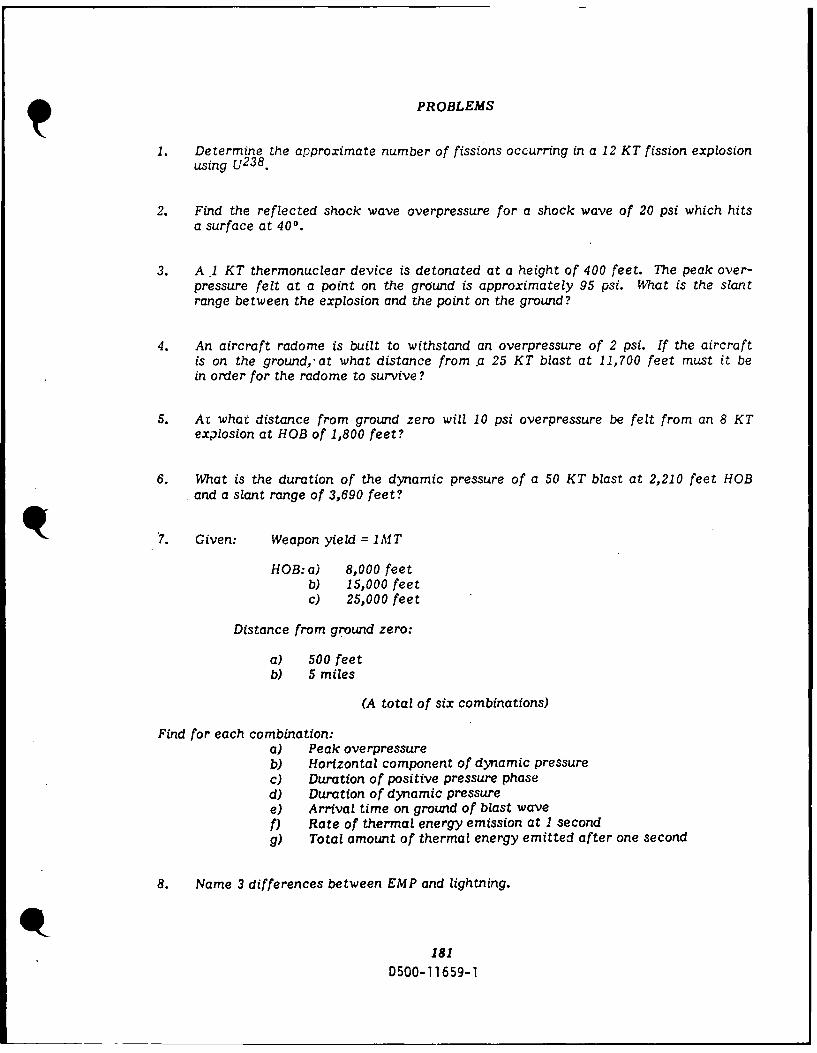
PROBLEMS
1. Determine the approximate number of fissions occurring in a 12 KT fission explosionusing U2 3 8 .
2. Find the reflected shock wave overpressure for a shock wave of 20 psi which hitsa surface at 40.
3. A .1 KT thermonuclear device is detonated at a height of 400 feet. The peak over-pressure felt at a point on the ground is approximately 95 psi. What is the slantrange between the explosion and the point on the ground?
4. An aircraft radome is built to withstand an overpressure of 2 psi. If the aircraftis on the ground,'at what distance from .a 25 KT blast at 11,700 feet must it bein order for the radome to survive?
5. At what distance from ground zero will 10 psi overpressure be felt from an 8 KTexplosion at HOB of 1,800 feet?
6. What is the duration of the dynamic pressure of a 50 KT blast at 2,210 feet HOBand a slant range of 3,690 feet?
7. Given: Weapon yield = 1MT
HOB: a) 8,000 feetb) 15,000 feetc) 25,000 feet
Distance from ground zero:
a) 500 feetb) 5 miles
(A total of six combinations)
Find for each combination:a) Peak overpressureb) Horizontal component of dynamic pressurec) Duration of positive pressure phased) Duration of dynamic pressuree) Arrival time on ground of blast wavef) Rate of thermal energy emission at 1 secondg) Total amount of thermal energy emitted after one second
8. Name 3 differences between EMP and lightning.
181D500-11659-1
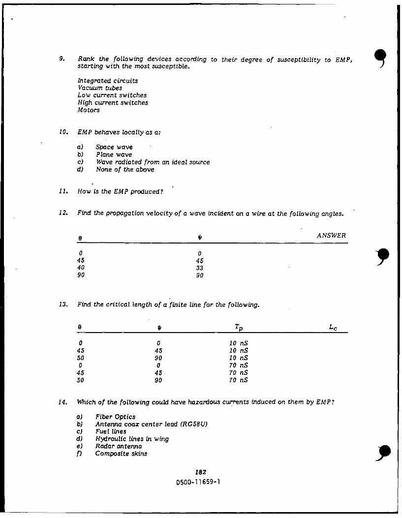
9. Rank the following devices according to their degree of susceptibility to EMP,starting with the most susceptible.
Integrated circuitsVacuum tubesLow current switchesHigh current switchesMotors
10. EMP behaves locally as a:
a) Space waveb) Plane wavec) Wave radiated from an ideal sourced) None of the above
11. How is the EMP produced?
12. Find the propagation velocity of a wave incident on a wire at the following angles.
'1 ANSWER
0 045 4540 33
90 90
13. Find the critical length of a finite line for the following.
9 Tp Lc
0 0 10 nS45 45 10 nS50 90 10 nS0 0 70 nS
45 45 70 nS50 90 70 nS
14. Which of the following could have hazardous currents induced on them by EMP?
a) Fiber Opticsb) Antenna coax center lead (RG58U)c) Fuel linesd) Hydraulic lines in winge) Radar antennaf) Composite skins
182
D500-11659-1
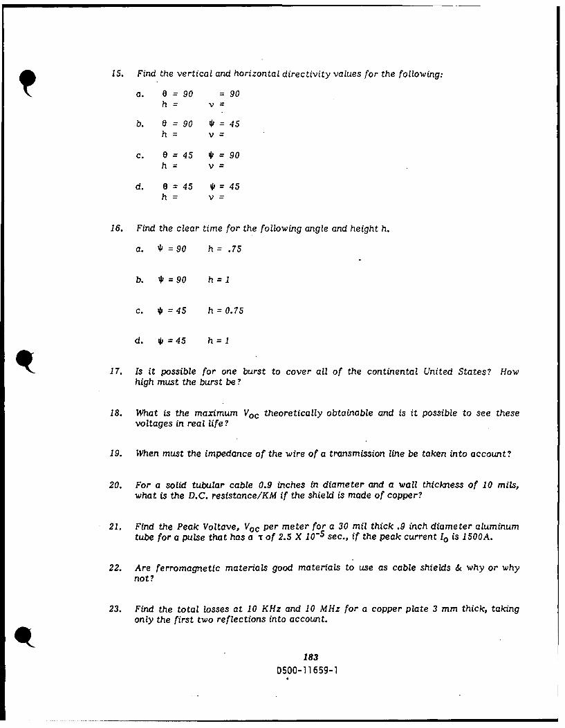
15. Find the vertical and horizontal directivity values for the following:
a. = 90 =90
b. 0= 90 4 =45
c. e =45 * = 90h= v=
d. 0= 45 41=45
16. Find the clear time for the following angle and height h.
a. 41=90 h = .75
b. 41=90 h=1
c. 41=45 h=0.75
d. 41=45 h=1
17. Is it possible for one burst to cover all of the continental United States? Howhigh must the burst be?
18. What is the maximum Voc theoretically obtainable and is it possible to see thesevoltages in real life?
19. When must the impedance of the wire of a transmission line be taken into account?
20. For a solid tubular cable 0.9 inches in diameter and a wall thickness of 10 mils,what is the D.C. resistance/KM if the shield is made of copper?
21. Find the Peak Voltave, Voc per meter for a 30 mil thick .9 inch diameter aluminumtube for a pulse that has a T of 2.5 X 10- 5 sec., if the peak current 10 is 1500A.
22. Are ferromagnetic materials good materials to use as cable shields & why or whynot?
23. Find the total losses at 10 KHz and 10 MHz for a copper plate 3 mm thick, takingonly the first two reflections into account.
183
0500-11659-1

24. A contractor wants to replace a spark gap on an antenna with a varistor.a. Is this safe ?b. Will it effect the performance of the system?c. Why or why not?
25. What is the purpose of conducting gaskets on doors and access panels?
26. Find what the skin depth is in earth at 1 MHz if the earth's conductivity 0=10 "
mhos and p = P o.
27. What would the main frequency component be for a tower that is 500 feet tall?
28. A transistor has an original hfe of 100, a life time damage constant "K" of 3.25.This transistor is exposed to 10 rads of radiation. It has a gain-bandwidth productof 100 x 106. What is the post radiation hfeo.
29. How much: a) steel, b) concrete, c) wood; is necessary to attenuate fission productradiation by 40 dB?
a)b)C)
30. A mod will replace cmos memory with "bubble" memory. If the same hardnessis to be maintained, is this a safe mod?
31. For the following circuits, the current transistor 2N3749 can no longer be obtained.Based only on the voltage gain, is a 2N3507 a suitable replacement? The outputvoltage must stay within f 10% of normal operating voltage.
V+ - 25Y
15K
V0
Sy
1
5K
1845SO0-11659-1
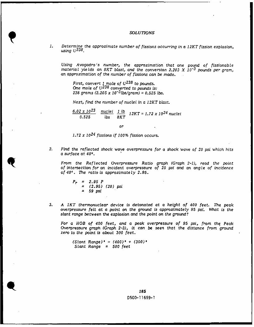
SOLUTIONS
1. Determine the approximate number of fissions occurring in a 12KT fission explosion,using U2 3 8 .
Using Avogadro 's number, the approximation that one pound of fissionablematerial yie lds an 8KT blast, and the conversion 2.203 X 10⁻³ pounds per gram,an approximation of the number of fissions can be made.
First, convert 1 mole of U2 3 8 to pounds.One mole of U2 3 8 converted to pounds is:238 grams (2.205 x i0-3lbs/gram) = 0.525 lbs.
Next, find the number of nuclei in a 12KT blast.
6.02 x 10²³ nuclei lZb 12KT = 1.72 x 1024 nuclei0.525 lbs 8KT
or
1.72 x 1024 fissions if 100% fission occurs.
2. Find the reflected shock wave overpressure for a shock wave of 20 psi which hitsa surface at 400.
From the Reflected Overpressure Ratio graph (Graph 2-i), read the pointof intersection for an incident overpressure of 20 psi and an angle of incidenceof 400. The ratio is approximately 2.95.
Pr = 2.95 P= (2.95) (20) psi= 59 psi
3. A 1KT thermonuclear device is detonated at a height of 400 feet. The peakoverpressure felt at a point on the ground is approximately 95 psi. What is theslant range between the explosion and the point on the ground?
For a HOB of 400 feet, and a peak overpressure of 95 psi, from the PeakOverpressure graph (Graph 2-3), it can be seen that the distance from groundzero to the point is about 300 feet.
(Slant Range)2 = (400)2 + (300)2Slant Range - 500 feet
185
D500-11659-1

4. An aircraft radome is built to withstand an overpressure of 2 psi. If the aircraftis on the ground, at what distance from a 25KT blast at 11,700 feet must it bein order for the radome to survive?
Using the Peak Overpressures on Ground graph (Graph 2-5), and normalizingto 1 KT:
h= h = 11700 = 4000 feetW1/ 3 (25)1/3
All distances from ground zero at 4000 feet HOB are less than 2 psi,therefore, the radome will survive at any distance.
5. At what distance from ground zero will 10 psi overpressure be felt from an 8KTexplosion at a HOB of 1,800 feet?
Using Peak Overpressure Graph 2-5, and:
h _ 1,800 = 900 feetWi1/ 3 81/3
10 psi is felt at dl < 930 feet and again at dl = 1250 feet.
d = d1 W1/ 3 = (930)(2) = 1860 feet or less
and
d = dwW I / 3 = (1250) (2) = 2500 feet
6. What is the duration of the dynamic pressure of a 5OKT blast at 2,210 feet HOBand a slant range of 3,690 feet?
Normalizing HOB and slant range
h 2,210 = 600 feethI = 1/3 = (50)1/3
= SR 3,690 1,000 feetSR 1 = W1 1 3 (50)1/3
r I = ((1,000)2 - (600)2) = 800 feet
from Graph 2-7:
Scaled dynamic pressure at HOB = 600 feet and r = 800 feet is 0.34 sec.
t = tI W 1/ 3 = .34 x 5011 3
= 1.25 sec.
186D500-11659-1

7. Given: Weapon yield = 1MT
HOB: a) 8,000 ftb) 15,000 ftC) 25,000 ft
Distance from ground zero:
a) 500 ftb) 5 mi
(A total of six combinations)
Find for each combination:
a) Peak overpressureb) Horizontal component of dynamic pressurec) Duration of positive pressure phased) Duration of dynamic pressuree) Arrival time on ground of blast wavef) Rate of thermal energy emissiong) Total amount of thermal energy emitted after one second
(1) W = 1 MT = 1000 KTHOB = 8000 ftr = 500 ft
r - W113 1,I000113 = 1
rI W1 15=10
rI -50 = 50.feet10
h= 10
hl
hi 8,000 = 800 feet10
(a) Peak overpressure (from Graph 2-4) = 29 psi
(b) Horizontal component (from Graph 2-6) = <I psi
c/d) From "pressure duration" Graph 2-7:
Positive phase duration = 0.16 Wi' 3 = 1.6 sec
Dynamic pressure duration = 0.33 W1/ 3 = 3.3 sec
187D500-11659-1
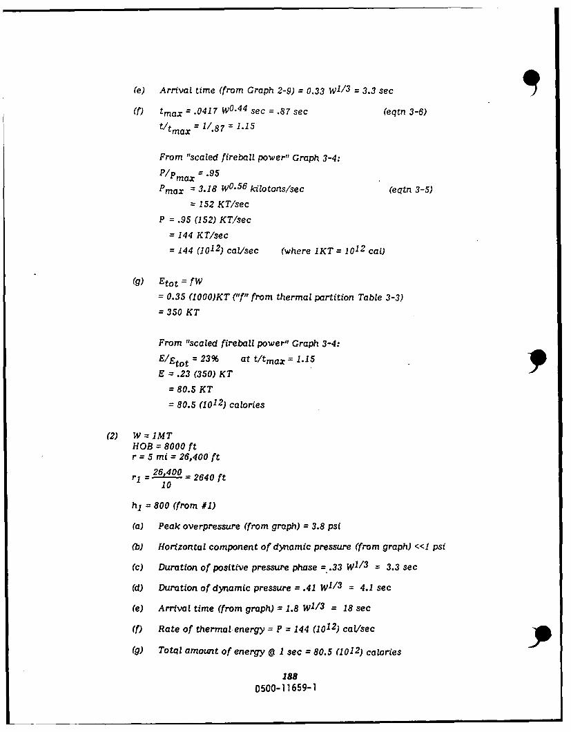
(e) Arrival time (from Graph 2-9) = 0.33 W1/ 3 = 3.3 sec
(f) tmax = .0417 W0"4 4 sec = .87 sec (eqtn 3-6)
t/tmax = 1/.87 = 1.15
From "scaled fireball power" Graph 3-4:P/Pmax = .95
Pmax = 3.18 W0 *5 6 kilotons/sec (eqtn 3-5)= 152 KT/sec
P = .95 (152) KT/sec
= 144 KT/sec
= 144 (1012) cal/sec (where 1KT = 1012 cal)
(g) Etot = fW
= 0.35 (1000)KT ("f" from thermal partition Table 3-3)
= 350 KT
From "scaled fireball power" Graph 3-4:
E/Etot = 23% at t/tmax = 1.15
E = .23 (350) KT
= 80.5 KT
= 80.5 (1012) calories
(2) W=1MTHOB = 8000 ftr = 5 mi = 26,400'ft
rl =26,400_ 2640 ft
10
h1 = 800 (from #1)
(a) Peak overpressure (from graph) = 3.8 psi
(b) Horizontal component of dynamic pressure (from graph) <<I psi
(c) Duration of positive pressure phase = .33 W1/ 3 = 3.3 sec
(d) Duration of dynamic pressure = .41 W1 / 3 = 4.1 sec
(e) Arrival time (from graph) = 1.8 W1 13 = 18 sec
(f) Rate of thermal energy = P = 144 (1012) cal/sec
(g) Total amount of energy 1 sec = 80.5 (1012) calories
188
D500-1 1659-1

NOTE: (f) and (g) are the same for part 2 of the problem as they werefor part 1, because ,,PI, and "Ell are assumed to be dependentupon only weapon yield and time for explosions up to 15,000feet.
(3) W=IMTHOB = 15,000 ftr = 500 ft
r, - - 50 ft10
h,= 15,000 = 1500 ft10
(a) Peak overpressure = 7.5 psi
(b) Horizontal component of dynamic pressure << 1 psi (off scale of availabledata)
(c) Duration of positive pressure = .30 (10) 3 sec
(d) Duration of dynamic pressure = .39 (10) 3.9 sec
(e) Arrival time = .9 (10) = 9 sec
(f) Rate of thermal emission:
(1) Without considering air density
P = 144 (1012) cal/sec (same as 1 and 2)
(2) considering air density
tmax = .038 W. 4 4 (air density ratio). 3 6 sec
= .038 (20.9)(.85) sec (air density ratio from chart)
= .68 sec
P/Pmax = .6 (from Graph 3-4
Pmax = (3.56 W 5 9 )/(air density ratio). 4 5 (eqtn 3-7)
= 2101.81
259 KT/sec
P = .6 (259) = 155 KT/bec
= 155 (1012) cal/sec
(NOTE: difference = 11 (10 1 2 )cal/sec)
(g) Total energy:
(1) without considering air density: (t/tmax 1.15)
E = 80.5 (1012) calories
189
D500-11659-1
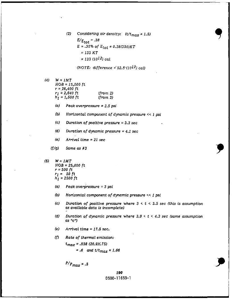
(2) Considering air density: (t/tmax = 1.5)
E/Etot = .38
E = .38% of Etot = 0.38(350)KT
= 133 KT
= 133 (1012) cal
(NOTE: difference -52.5-(102) cal)
(4) W=IMTHOB = 15,000 ftr =.26,400 ftrI = 2,640 ft (from 2)hl = 1,500 ft (from 3)
(a) Peak overpressure = 2.5 psi
(b) Horizontal component of dynamic pressure << 1 psi
(c) Duration of positive pressure = 3.3 sec
(d) Duration of dynamic pressure = 4.1 sec
(e) Arrival time = 21 sec
(fig) Same as #3
(5) W=IMTHOB = 25,000 ftr = 500 ftr= 50 fthl = 2500 ft
(a) Peak overpressure = 3 psi
(b) Horizontal component of dynamic pressure << 1 psi
(c) Duration of positive pressure where 3 < t < 3.5 sec (this is assumptionas available data is incomplete)
d) Duration of dynamic pressure where 3.9 < t < 4.3 sec (same assumptionas "C")
(e) Arrival time = 17.5 sec.
(f) Rate of thermal emission:
tmax = .038 (20.9)(.75)
= .6 and t/tmax = 1.66
P/Pmax = .5
190D500-11659-1

P = .5 (3.56W' 5 9 /.45. 4 5)KT/sec
= 150 KT/sec
= 150 (1012) caL/sec
(g) Total thermal energy (t/tmax 1.66)
E/Etot = 4
E = 0.14 FW
= 0.14 (.41)(1000)
= 164 KT
= 164 (1012) calories
(6) W= 1 MTHOB = 25,000 ftr = 26,400 ftr= 2640 fth= 2500 ft
(a) Peak overpressure = 1.75 psi
(b) Horizontal component of dynamic pressure <<I psi
(c) Duration of positive pressure = unknown
(d) Duration of dynamic pressure = unknown
(NOTE: data insufficient for "c" and "d")
(e) Arrival time = 26 sec.
(f/g) Same as #5
8. Name 3 differences between EMP and lightning.
a) Pulse with I to 2 microseconds vs. 100's of microseconds.b) Rise time is in the nanoseconds for EMP vs. microseconds for lightning.c) EMP has a larger amplitude, 50K Vim vs. 100 to 1,000 V/m.d) area of coverage.e) frequency spectrum
9. Rank the following devices according to their degree of susceptibility to EMP,starting with the most susceptible.
1. Integrated circuits5. Vacuum tubes2. Low current switches3. High current switches4. Motors
191
D500-11659-1

10. EMP behaves locally as a:
a) Space waveb) Plane wavec) Wave radiated from an ideal sourced) None of the above
11. How is the EMP produced?
Gamma-rays strip off electrons by the compton effect. These electrons spiralaround the earth's magnetic fields. This produces a net current.
12. Find the propagation velocity of a wave incident on a wire at the following angles.
V = C c=3x10⁸ m /secCos C Cos *
ANSWER6 cos e cos *
0 1 0 1 3 x 10⁸
45 .707 45 .707 6 x 10⁸
40 .766 33 .839 4.67 x 10896 0 90 0 M
13. Find the critical length of a finite line for the following:
Lc = cTP1 1-cos8 cos *J c = 3 x 10⁸ m/sec
9 Tp Lc
0 0. 10 nS (very long)45 45 10 nS 6 METERS50 90 10 nS 3 METERS0 0 70 nS (very long)
45 45 70 nS 42 METERS50 90 70 nS 21 METERS
14. Which of the following could have hazardous currents induced on them by EMP?
a) Fiber Opticsb) Antenna coax center lead (Rg58u)c) Fuel linesd) Hydraulic lines in winge) Radar antenna77 Composite skins
192
D500-11659-1
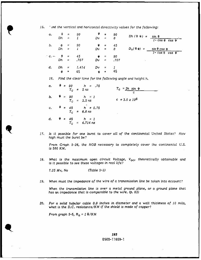
15. 'Lnd the vertical and horizontal directivity values for the following:
a. a = 90 0 = 90Dh = 1 Dv = 0 Dh (04@) = sin 81- cos O cos 0
b. 0 90 4 = 45Dh I Dv = 0 Dv( O ) = sin 4 cose
1-cose cos 40C.-- 0 = 45 4 = 90
Dh = .707 Dv = .707
d. Dh = 1.414 Dv = 1
e = 45 * = 45
16. Find the clear time for the following angle and height h.
a. o = 90 h = .75Tc = 5ns Tc =2h sin 4
c
b. *= 90 h =1Tc = .5nsc =3.0x10⁸T c = 3.5 ns
C. 4 45 h = 0.75Tc = 6.6ns
d. 4'= 45 h =1Tc = 4.714 ns
17. Is it possible for one burst to cover all of the continental United States? Howhigh must the burst be?
From Graph 5-26, the HOB necessary to completely cover the continental U.S.is 500 KM.
18. What is the maximum open circuit Voltage, Voc, theoretically obtainable andis it possible to see these voltages in real life?
7.25 Mv, No (Table 5-1)
19. When must the impedance of the wire of a transmission line be taken into account?
When the transmission line is over a metal ground plane, or a ground plane thathas an impedance that is comparable to the wire. (p. 83)
20. For a solid tubular cable 0.9 inches in diameter and a wall thickness of 10 mils,what is the D.C. resistance/KM if the shield is made of copper?
From graph 5-5, R O = I I7/KM
193D500-11659-1

21. Find the peak voltage, Voc per meter for a 30 mil thick .9 inch diameter aluminumtube for a pulse that has a of 2.5 X 10- 5 sec., if the peak current 1o is 1500A.
R= 4,621 volts/r R. from fig 5.5; T from fig 5.6, T = T
ocp { .77 4.6.2.1 v/m
22. Are ferromagnetic materials good materials to use as cable shields & why or whynot?
NO. Ferromagnetic materials loose their shield effectiveness when they become-aturated.
23. Find the total losses at 10 KHz and 10 MHz for a copper plate 3 mm thick, takingonly the first two reflections into account. Table 5-2 and handbook values
~~ +R- (8,69z )+SIOK =A10K + R10K =39.5 + 128 = I67.5dB., Using S = A + '1R =%.-z) + R
6S10M = A0M + RIOM = 1241.4 + 118 1,359.4dB T =5.8x mhos/m
cuR,= 108 + 10 log t= 0 = 4 x 10- 7 h e n r y s m , f in MHz
24. A contractor wants to replace a spark gap on an antenna with a varistor.a. Is this safe?b. Will it effect the performance of the system?c. Why or why not?
a. If the varistor is fast enough, yes.b. YesC. It is in the line all the time and effects the impedance.
25. What is the purpose of conducting gaskets on doors and access panels?
To prevent EMP energy from entering the gap between the door and door frame.
26. Find what the skin depth is in earth at 1 MHz if the earth's conductivity (og) is1O" mhos and U= L 0 .
6 2 2 1 .915m
o 9 (2wf)(410-)(I0- ) 2(1 00
27. What would the main frequency component be for a tower that is 500 feet tall?
c=9.84x10⁸ /sec 8 =4x500=2000'f,. - 9.84 x 10⁸
A 2000 since antenna is J wave length
f = 49z KHz (using antenna constant 234, f = 2-34 - 468 KI-r)
500
194
0500-11659-1
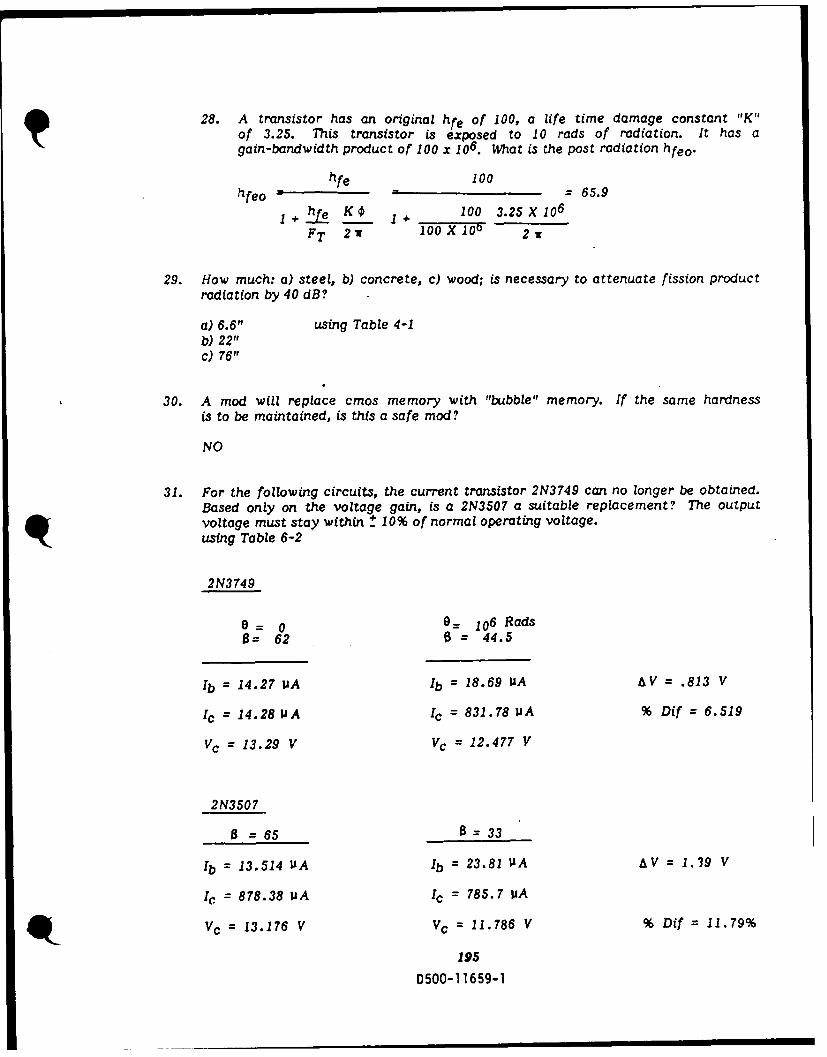
28. A transistor has an original hfe of 100, a life time damage constant "K"of 3.25. This transistor is exposed to 10 rads of radiation. It has again-bandwidth product of 100 x 106. What is the post radiation hfeo.
hfe 100
hfeo - 100 = 65.9
+ hfe K I 1 100 3.25X 10⁶
FT 2 w 100 X 106 2:
29. How much: a) steel, b) concrete, c) wood; is necessary to attenuate fission productradiation by 40 dB?
a) 6.6" using Table 4-1b) 22"c) 76"
30. A mod will replace cmos memory with "bubble" memory. If the same hardnessis to be maintained, is this a safe mod?
NO
31. For the following circuits, the current transistor 2N3749 can no longer be obtained.Based only on the voltage gain, is a 2N3507 a suitable replacement? The outputvoltage must stay within + 10% of normal operating voltage.using Table 6-2
2N3749
a = 0 G= 1 06 RadsO= 62 = 44.5
Ib = 14.27 P1A Ib = 18.69 UA A V = .813 V
1c = 14.28 IJA Ic = 831.78 v A % Dif = 6.519
Vc = 13.29 V Vc = 12.477 V
2N3507
0 = 65 8=33
Ib = 13.514 UA Ib = 23.81 IsA AV = 1.39 V
Ic = 878.38 MA Ic = 785.7 1IA
Vc = 13.176 V Vc = 11.786 V % Dif = 11.79%
195
D500-11 659-1
ACTIVE SHEET RECORD
ADDED SHEETS ADDED SHEETS
SHEET SHEET SHEET . SHEET SHEET SHEETNO. > NO. > NO. > NO. > NO. > NO. >
LU Lu Lu U. u Lcr 0:1
1 46472 48
3 494 506 516 527 538 549 5510 56
11 5712 5813 5914 60is 6116 6217 6318 6419 6920 6421 6722 6823 6924 6925 7026 7127 7228 7329 7530 7631 7632 7833 7834 7935 8036 8137 8238 8339 8440 8541 8642 8743 8844 8945 g
196D500-11659-1
00 0 a CRI 3. 4/7
THE " A W COMPANY
ACTIVE SHEET RECORD
ADDED SHEETS ADDED SHEETS
SHEET SHEET SHEET SHEET SHEET SHEET iNO. > NO. > NO. > NO. > NO. > NO. >
91 13692 13793 13894 13995 14096 14197 14298 14399 144100 145101 146102 147103 148104 149105 150106 151107 152108 153109 154110 15511115
ill 156112 157113 158114 159115 160116 161117 162118 163119 164120 165121 166122 167123 168124 169125 170126 171127 172128 173129 174130 175131 176132 177133 178134 179135 180
197D500-11659-1
00 4000 a Is$ CR10. 4/ 71

-ACUJ'VE SREEC j9RfS
ADDED SHEETS ._ ADDED-SHEETS
SHEET SHEET SHEET SH5 H HET SHEETNO. > NO. > NO. > NO > NO >
LU UL LU - L NO. NO
181182183184185186187188189-190191192-193194195196197:198-
4,L:
198
D500-11 659 l..-
00 OOO 2111 0iG. 4/t


![Compact and Discreet - yaesu.ru · Battery Life [5-5-90 duty with battery saver]MDC-1200® Features: - MDC-1200® ANI - MDC-1200® Call Alert - MDC-1200® Sel Call - MDC-1200® Radio](https://img.dokumen.tips/doc/110x75/5e80d3de6005c20fb639820d/compact-and-discreet-yaesuru-battery-life-5-5-90-duty-with-battery-savermdc-1200.jpg)