Embed Size (px)
Citation preview
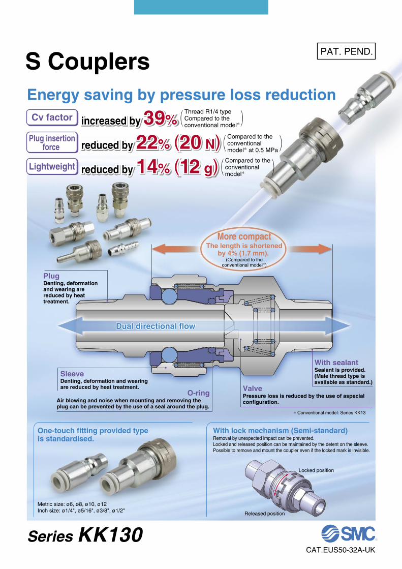
increased by 39%
reduced by 22% (20 N)
reduced by 14% (12 g)
increased by 39%
reduced by 22% (20 N)
reduced by 14% (12 g)
Series KK130
S Couplers
increased by 39%
reduced by 22% (20 N)
reduced by 14% (12 g)
Air blowing and noise when mounting and removing the plug can be prevented by the use of a seal around the plug.
Denting, deformation and wearing are reduced by heat treatment.
Denting, deformation and wearing are reduced by heat treatment.
Sealant is provided. (Male thread type is available as standard.)
Dual directional flowDual directional flow
∗ Conventional model: Series KK13
ValveO-ring
Sleeve
With sealant
Pressure loss is reduced by the use of aspecial configuration.
Plug
Energy saving by pressure loss reduction
Lightweight
One-touch fitting provided type is standardised.
With lock mechanism (Semi-standard)Removal by unexpected impact can be prevented. Locked and released position can be maintained by the detent on the sleeve. Possible to remove and mount the coupler even if the locked mark is invisible.
Locked position
Released position
Metric size: ø6, ø8, ø10, ø12Inch size: ø1/4", ø5/16", ø3/8", ø1/2"
More compact
(Compared to theconventional model∗)
Plug insertionforce
Cv factor
PAT. PEND.
The length is shortened by 4% (1.7 mm).
Thread R1/4 typeCompared to the conventional model∗
Compared to the conventional model∗ at 0.5 MPa
Compared to the conventional model∗
CAT.EUS50-32A-UK
0
0.5
0.6
0.5 1 1.2 1.5 2
Inle
t pre
ssur
e (M
Pa)
Outlet flow rate (m3/min (ANR))
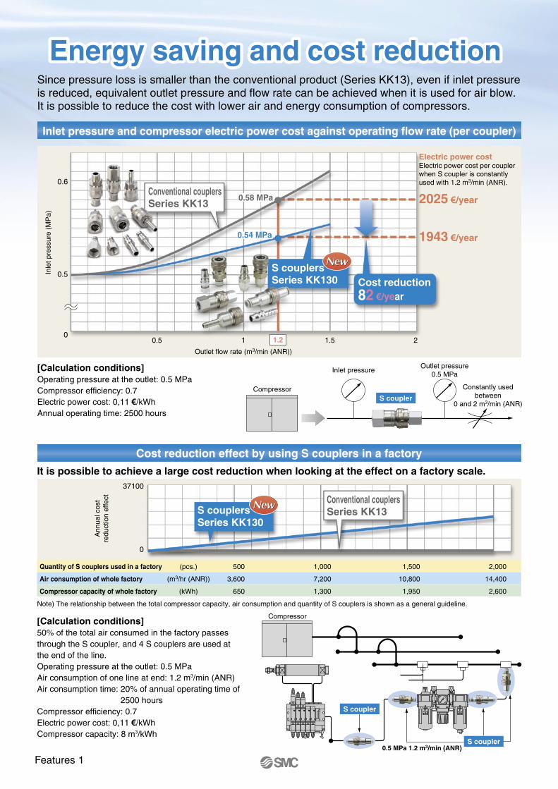
Electric power costElectric power cost per coupler when S coupler is constantly used with 1.2 m3/min (ANR).
2025 €/year
1943 €/year
0.58MPa
0.54MPa
0.58 MPa
0.54 MPa
Cost reduction82 €/year
S couplersSeries KK130
Conventional couplersSeries KK13
Quantity of S couplers used in a factory
Air consumption of whole factory
Compressor capacity of whole factory
(pcs.)
(m3/hr (ANR))
(kWh)
500
3,600
650
1,000
7,200
1,300
1,500
10,800
1,950
2,000
14,400
2,600
Ann
ual c
ost
redu
ctio
n ef
fect
S couplersSeries KK130
Conventional couplersSeries KK13
37100
0
Inlet pressureOutlet pressure
0.5 MPa
Constantly usedbetween
0 and 2 m3/min (ANR)S coupler
Compressor
Compressor
0.5 MPa 1.2 m3/min (ANR)
S coupler
S coupler
Since pressure loss is smaller than the conventional product (Series KK13), even if inlet pressure is reduced, equivalent outlet pressure and flow rate can be achieved when it is used for air blow. It is possible to reduce the cost with lower air and energy consumption of compressors.
Inlet pressure and compressor electric power cost against operating flow rate (per coupler)
[Calculation conditions] Operating pressure at the outlet: 0.5 MPaCompressor efficiency: 0.7Electric power cost: 0,11 €/kWhAnnual operating time: 2500 hours
Cost reduction effect by using S couplers in a factory
It is possible to achieve a large cost reduction when looking at the effect on a factory scale.
Note) The relationship between the total compressor capacity, air consumption and quantity of S couplers is shown as a general guideline.
[Calculation conditions] 50% of the total air consumed in the factory passes through the S coupler, and 4 S couplers are used at the end of the line. Operating pressure at the outlet: 0.5 MPaAir consumption of one line at end: 1.2 m3/min (ANR)Air consumption time: 20% of annual operating time of
2500 hoursCompressor efficiency: 0.7Electric power cost: 0,11 €/kWhCompressor capacity: 8 m3/kWh
Energy saving and cost reduction Energy saving and cost reduction
Features 1
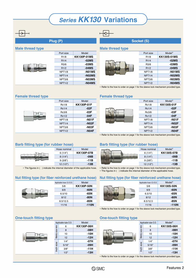
Male thread type
Female thread type
Male thread type
Female thread type
Barb fitting type (for rubber hose) Barb fitting type (for rubber hose)
Nut fitting type (for fiber reinforced urethane hose)Nut fitting type (for fiber reinforced urethane hose)
One-touch fitting typeOne-touch fitting type
Plug (P) Socket (S)
Port size
R1/8
R1/4
R3/8
R1/2
NPT1/8
NPT1/4
NPT3/8
NPT1/2
KK130P-01MS-02MS-03MS-04MS-N01MS-N02MS-N03MS-N04MS
Model
Port size
Rc1/8
Rc1/4
Rc3/8
Rc1/2
NPT1/8
NPT1/4
NPT3/8
NPT1/2
KK130P-01F-02F-03F-04F-N01F-N02F-N03F-N04F
Model
Hose nominal
6 (1/4")
8 (1/4")
9 (3/8")
12 (1/2")
∗ The figures in ( ) indicate the internal diameter of the applicable hose.
KK130P-07B-09B-11B-13B
Model
Applicable hose I.D./O.D.
5/8
6/9
6.5/10
8/12
8.5/12.5
11/16
KK130P-50N-60N-65N-80N-85N-110N
Model
Port size
R1/8
R1/4
R3/8
R1/2
NPT1/8
NPT1/4
NPT3/8
NPT1/2
KK130S-01MS-02MS-03MS-04MS-N01MS-N02MS-N03MS-N04MS
Model∗
Port size
Rc1/8
Rc1/4
Rc3/8
Rc1/2
NPT1/8
NPT1/4
NPT3/8
NPT1/2
KK130S-01F-02F-03F-04F-N01F-N02F-N03F-N04F
Model∗
Hose nominal
6 (1/4")
8 (1/4")
9 (3/8")
12 (1/2")
KK130S-07B-09B-11B-13B
Model∗
Applicable hose I.D./O.D.
5/8
6/9
6.5/10
8/12
8.5/12.5
11/16
KK130S-50N-60N-65N-80N-85N-110N
Model∗
Applicable tube O.D.
6
8
10
12
1/4"
5/16"
3/8"
1/2"
KK130P-06H-08H-10H-12H-07H-09H-11H-13H
Model
Met
ric s
ize m
mIn
ch s
ize
Met
ric s
ize m
mIn
ch s
ize
Applicable tube O.D.
6
8
10
12
1/4"
5/16"
3/8"
1/2"
KK130S-06H-08H-10H-12H-07H-09H-11H-13H
Model∗
∗ Refer to the how to order on page 1 for the sleeve lock mechanism provided type.
∗ Refer to the how to order on page 1 for the sleeve lock mechanism provided type.
∗ Refer to the how to order on page 1 for the sleeve lock mechanism provided type.∗ The figures in ( ) indicate the internal diameter of the applicable hose.
∗ Refer to the how to order on page 1 for the sleeve lock mechanism provided type.
∗ Refer to the how to order on page 1 for the sleeve lock mechanism provided type.
Series KK130 Variations
Features 2
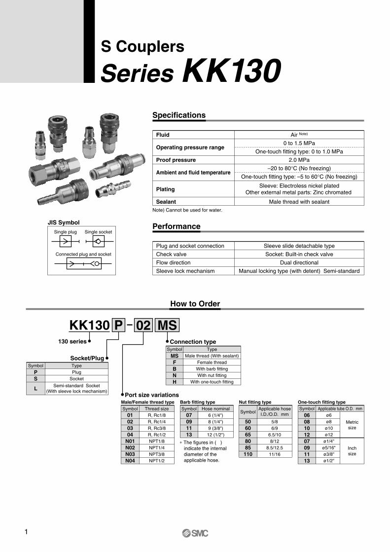
S Couplers
Series KK130Specifications
Performance
Sleeve slide detachable type
Socket: Built-in check valve
Dual directional
Manual locking type (with detent) Semi-standard
Plug and socket connection
Check valve
Flow direction
Sleeve lock mechanism
JIS Symbol
Single plug Single socket
Connected plug and socket
Air Note)
0 to 1.5 MPa
One-touch fitting type: 0 to 1.0 MPa
2.0 MPa
–20 to 80°C (No freezing)
One-touch fitting type: –5 to 60°C (No freezing)
Male thread with sealant
Fluid
Operating pressure range
Proof pressure
Ambient and fluid temperature
Plating
SealantNote) Cannot be used for water.
Sleeve: Electroless nickel platedOther external metal parts: Zinc chromated
How to Order
130 series
KK130 P
Socket/Plug
Hose nominal6 (1/4")8 (1/4")9 (3/8")
12 (1/2")
Barb fitting typeSymbol
07091113
∗ The figures in ( ) indicate the internal diameter of the applicable hose.
Port size variations
02 MSConnection type
Nut fitting typeApplicable tube O.D. mm
ø6ø8
ø10ø12
ø1/4"ø5/16"ø3/8"ø1/2"
Metricsize
Inchsize
One-touch fitting typeSymbol
0608101207091113
Thread sizeR, Rc1/8R, Rc1/4R, Rc3/8R, Rc1/2NPT1/8NPT1/4NPT3/8NPT1/2
Male/Female thread typeSymbol
01020304
N01N02N03N04
TypePlug
Socket
Semi-standard Socket(With sleeve lock mechanism)
Symbol
PS
L
TypeMale thread (With sealant)
Female threadWith barb fittingWith nut fitting
With one-touch fitting
Symbol
MSFBNH
Applicable hoseI.D./O.D. mm
5/86/9
6.5/108/12
8.5/12.511/16
Symbol
5060658085110
Construction
No.123456789
101112
Description MaterialSocket bodySleeveValveMain bodySleeve springValve springHolderPlug O-ringSealSteel ballCassetteSeal
Structural steelSteel wireSteel wireSteel wire
Stainless steelStainless steel
Steel bandNBRNBRSUJ—
NBR
NoteZinc chromated
Electroless nickel platedZinc chromatedZinc chromated
Zinc chromated
No.1
1112
Description MaterialPlugCassetteSeal
Structural steel—
NBR
NoteZinc chromated
Flow-rate Characteristics [Representative Value]
Plug Socket
Plug
<With one-touch fitting> <With one-touch fitting>
Socket
Figure: Connected plug and socket
KK130P KK130Sq
!1!1 !2!2
qw ert youi!0
Malethread
Femalethread
With nutfitting
Withone-touch
fitting
With barbfitting
Connection type
ConnectionSymbolType
-01MS-02MS-03MS-04MS-01F-02F-03F-04F-07B-09B-11B-13B-50N-60N-65N-80N-85N-110N-06H-08H-10H-12H
R1/8R1/4R3/8R1/2Rc1/8Rc1/4Rc3/8Rc1/2
6 (1/4")8 (1/4")10 (3/8")12 (1/2")
5/86/9
6.5/108/12
8.5/12.511/16
ø6ø8ø10ø12
SonicconductanceC [dm3/(s·bar)]
Criticalpressureratio b
Flowcoefficient
Cv
Effectivearea
S [mm2]
4.27.07.07.06.07.07.07.02.03.06.07.02.03.54.27.07.07.02.04.47.07.0
0.40.40.50.50.50.50.50.50.40.40.50.50.40.40.40.40.40.50.40.50.50.5
1.21.92.12.11.82.12.12.10.50.81.82.10.51.01.21.91.92.10.51.31.82.1
21353535303535351015303510182135353510223535
∗ This flow-rate characteristic test method complies with JIS B 8390 (Pneumatic fluid power – Components using compressible fluids – Determination of flow-rate characteristics)
∗ The figures are representative values when the same type of plug and socket are connected.
0
1
2
3
4
5
0 0.1 0.2 0.3 0.4 0.5 0.6 0.7 0.8 0.9 1
Pressure MPa
Flo
w r
ate
m3 /
min
(A
NR
)
KK130P-01MS+KK130S-01MS
KK130P-02MS+KK130S-02MSKK130P-03MS+KK130S-03MSKK130P-04MS+KK130S-04MS
S Couplers Series KK130
1

S Couplers
Series KK130Specifications
Performance
Sleeve slide detachable type
Socket: Built-in check valve
Dual directional
Manual locking type (with detent) Semi-standard
Plug and socket connection
Check valve
Flow direction
Sleeve lock mechanism
JIS Symbol
Single plug Single socket
Connected plug and socket
Air Note)
0 to 1.5 MPa
One-touch fitting type: 0 to 1.0 MPa
2.0 MPa
–20 to 80°C (No freezing)
One-touch fitting type: –5 to 60°C (No freezing)
Male thread with sealant
Fluid
Operating pressure range
Proof pressure
Ambient and fluid temperature
Plating
SealantNote) Cannot be used for water.
Sleeve: Electroless nickel platedOther external metal parts: Zinc chromated
How to Order
130 series
KK130 P
Socket/Plug
Hose nominal6 (1/4")8 (1/4")9 (3/8")
12 (1/2")
Barb fitting typeSymbol
07091113
∗ The figures in ( ) indicate the internal diameter of the applicable hose.
Port size variations
02 MSConnection type
Nut fitting typeApplicable tube O.D. mm
ø6ø8
ø10ø12
ø1/4"ø5/16"ø3/8"ø1/2"
Metricsize
Inchsize
One-touch fitting typeSymbol
0608101207091113
Thread sizeR, Rc1/8R, Rc1/4R, Rc3/8R, Rc1/2NPT1/8NPT1/4NPT3/8NPT1/2
Male/Female thread typeSymbol
01020304
N01N02N03N04
TypePlug
Socket
Semi-standard Socket(With sleeve lock mechanism)
Symbol
PS
L
TypeMale thread (With sealant)
Female threadWith barb fittingWith nut fitting
With one-touch fitting
Symbol
MSFBNH
Applicable hoseI.D./O.D. mm
5/86/9
6.5/108/12
8.5/12.511/16
Symbol
5060658085
110
Construction
No.123456789
101112
Description MaterialSocket bodySleeveValveMain bodySleeve springValve springHolderPlug O-ringSealSteel ballCassetteSeal
Structural steelSteel wireSteel wireSteel wire
Stainless steelStainless steel
Steel bandNBRNBRSUJ—
NBR
NoteZinc chromated
Electroless nickel platedZinc chromatedZinc chromated
Zinc chromated
No.11112
Description MaterialPlugCassetteSeal
Structural steel—
NBR
NoteZinc chromated
Flow-rate Characteristics [Representative Value]
Plug Socket
Plug
<With one-touch fitting> <With one-touch fitting>
Socket
Figure: Connected plug and socket
KK130P KK130Sq
!1!1 !2!2
qw ert youi!0
Malethread
Femalethread
With nutfitting
Withone-touch
fitting
With barbfitting
Connection type
ConnectionSymbolType
-01MS-02MS-03MS-04MS-01F-02F-03F-04F-07B-09B-11B-13B-50N-60N-65N-80N-85N-110N-06H-08H-10H-12H
R1/8R1/4R3/8R1/2Rc1/8Rc1/4Rc3/8Rc1/2
6 (1/4")8 (1/4")
10 (3/8")12 (1/2")
5/86/9
6.5/108/12
8.5/12.511/16
ø6ø8ø10ø12
SonicconductanceC [dm3/(s·bar)]
Criticalpressureratio b
Flowcoefficient
Cv
Effectivearea
S [mm2]
4.27.07.07.06.07.07.07.02.03.06.07.02.03.54.27.07.07.02.04.47.07.0
0.40.40.50.50.50.50.50.50.40.40.50.50.40.40.40.40.40.50.40.50.50.5
1.21.92.12.11.82.12.12.10.50.81.82.10.51.01.21.91.92.10.51.31.82.1
21353535303535351015303510182135353510223535
∗ This flow-rate characteristic test method complies with JIS B 8390 (Pneumatic fluid power – Components using compressible fluids – Determination of flow-rate characteristics)
∗ The figures are representative values when the same type of plug and socket are connected.
0
1
2
3
4
5
0 0.1 0.2 0.3 0.4 0.5 0.6 0.7 0.8 0.9 1
Pressure MPa
Flo
w r
ate
m3 /
min
(A
NR
)
KK130P-01MS+KK130S-01MS
KK130P-02MS+KK130S-02MSKK130P-03MS+KK130S-03MSKK130P-04MS+KK130S-04MS
S Couplers Series KK130
2
AL2Plug dimension when socket is connected.
L1
ø13
H
T
L1
L2Plug dimension when socket is connected.
ø13
H
T
L1øD
1øD
2
24L2Plug dimension when socket is connected.
ø13
L1
ø26
A
H
T
ø26
L1H
T
ø26
L124
øD
L3
L3
L3
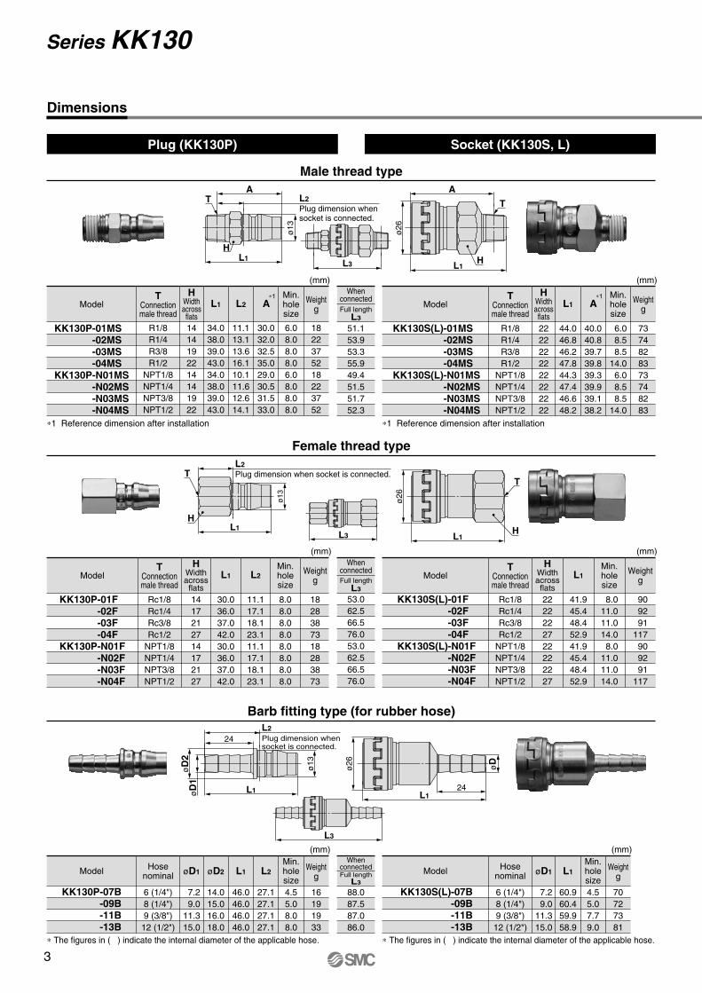
Dimensions
Male thread type
Plug (KK130P) Socket (KK130S, L)
Female thread type
Barb fitting type (for rubber hose)
Hosenominal
6 (1/4")8 (1/4")9 (3/8")12 (1/2")
7.2 9.011.315.0
øD2
14.015.016.018.0
L1 L2
46.046.046.046.0
27.127.127.127.1
øD1
16191933
4.55.08.08.0
Min.holesize
Weightg
Model
KK130P-07B-09B-11B-13B
Hosenominal
6 (1/4")8 (1/4")9 (3/8")12 (1/2")
7.2 9.011.315.0
L1
60.960.459.958.9
øD1
70727381
4.55.07.79.0
Min.holesize
Weightg
Model
KK130S(L)-07B-09B-11B-13B
88.087.587.086.0
∗ The figures in ( ) indicate the internal diameter of the applicable hose. ∗ The figures in ( ) indicate the internal diameter of the applicable hose.
(mm) (mm)
53.062.566.576.053.062.566.576.0
TConnectionmale thread
Rc1/8Rc1/4Rc3/8Rc1/2
NPT1/8NPT1/4NPT3/8NPT1/2
1417212714172127
L1
30.036.037.042.030.036.037.042.0
L2
11.117.118.123.111.117.118.123.1
HWidthacrossflats
1828387318283873
8.08.08.08.08.08.08.08.0
Min.holesize
WeightgModel
KK130P-01F-02F-03F-04F
(mm)
TConnectionmale thread
Rc1/8Rc1/4Rc3/8Rc1/2
NPT1/8NPT1/4NPT3/8NPT1/2
2222222722222227
L1
41.945.448.452.941.945.448.452.9
HWidthacrossflats
90 92 91117 90 92 91117
8.011.011.014.0 8.011.011.014.0
Min.holesize
WeightgModel
KK130S(L)-01F-02F-03F-04F
(mm)
51.153.953.355.949.451.551.752.3
Full lengthL3
Whenconnected
Full lengthL3
Whenconnected
Full lengthL3
Whenconnected
TConnectionmale thread
R1/8R1/4R3/8R1/2
NPT1/8NPT1/4NPT3/8NPT1/2
1414192214141922
34.038.039.043.034.038.039.043.0
11.113.113.616.110.111.612.614.1
HWidthacrossflats
L1 L2 A∗1
30.032.032.535.029.030.531.533.0
1822375218223752
6.08.08.08.06.08.08.08.0
Min.holesize
WeightgModel
KK130P-01MS-02MS-03MS-04MS
∗1 Reference dimension after installation
TConnectionmale thread
R1/8R1/4R3/8R1/2
NPT1/8NPT1/4NPT3/8NPT1/2
2222222222222222
44.046.846.247.844.347.446.648.2
HWidthacrossflats
L1 A∗1
40.040.839.739.839.339.939.138.2
7374828373748283
6.0 8.5 8.514.0 6.0 8.5 8.514.0
Min.holesize
WeightgModel
KK130S(L)-01MS-02MS-03MS-04MS
KK130S(L)-N01MS-N02MS-N03MS-N04MS
∗1 Reference dimension after installation
(mm) (mm)
KK130P-N01MS-N02MS-N03MS-N04MS
KK130P-N01F-N02F-N03F-N04F
KK130S(L)-N01F-N02F-N03F-N04F
Series KK130
ø13øD
M
L2Plug dimension when socket is connected.
L1
ø13
L2Plug dimension when socket is connected.
ML1
H1H2
L3
L3
ø26
L1
M
H2H1
ø26
L1
øD
M
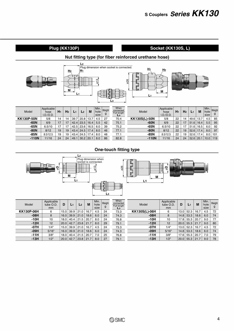
Nut fitting type (for fiber reinforced urethane hose)
Plug (KK130P) Socket (KK130S, L)
70.475.175.277.177.182.8
One-touch fitting type
73.374.376.879.173.374.376.879.1
Applicablehose
I.D./O.D.5/86/9
6.5/108/12
8.5/12.511/16
141717191924
H2H1
141717191924
L1
39.742.442.543.443.449.1
L2
20.823.523.624.524.530.2
274239464886
4.55.56.08.08.08.0
13.716.416.517.417.420.1
M Weightg
Min.holesize
Model
KK130P-50N -60N -65N -80N -85N -110N
Applicablehose
I.D./O.D.5/86/9
6.5/108/12
8.5/12.511/16
222222222224
H2
141717191924
H1 L1 M
49.651.651.652.652.652.6
85 95 92 97101119
13.716.416.517.417.420.1
Weightg
Model
KK130S(L)-50N -60N -65N -80N -85N -110N
4.5 5.5 6.0 8.0 8.010.0
Min.holesize
Applicabletube O.D.
mm68
1012
1/4"5/16"3/8"1/2"
13.014.817.820.013.014.817.620.0
L1
52.353.355.355.352.353.355.355.3
D M
7274778072747978
16.718.620.721.716.718.620.721.7
Weightg
Min.holesize
Model
KK130S(L)-06H-08H-10H-12H-07H-09H-11H-13H
4.56.09.09.04.56.07.09.0
Applicabletube O.D.
mm681012
1/4"5/16"3/8"1/2"
15.016.018.020.015.016.018.020.0
L1D
39.939.940.442.739.939.940.442.7
L2
21.021.021.523.821.021.021.523.8
2424242924242527
16.718.620.721.716.718.620.721.7
4.56.08.08.04.56.07.08.0
M Weightg
Model
KK130P-06H-08H-10H-12H-07H-09H-11H-13H
Min.holesize
Full lengthL3
Whenconnected
Full lengthL3
Whenconnected
S Couplers Series KK130
3
AL2Plug dimension when socket is connected.
L1
ø13
H
T
L1
L2Plug dimension when socket is connected.
ø13
H
T
L1øD
1øD
2
24L2Plug dimension when socket is connected.
ø13
L1
ø26
A
H
T
ø26
L1H
T
ø26
L124
øD
L3
L3
L3
Dimensions
Male thread type
Plug (KK130P) Socket (KK130S, L)
Female thread type
Barb fitting type (for rubber hose)
Hosenominal
6 (1/4")8 (1/4")9 (3/8")12 (1/2")
7.2 9.011.315.0
øD2
14.015.016.018.0
L1 L2
46.046.046.046.0
27.127.127.127.1
øD1
16191933
4.55.08.08.0
Min.holesize
Weightg
Model
KK130P-07B-09B-11B-13B
Hosenominal
6 (1/4")8 (1/4")9 (3/8")
12 (1/2")
7.2 9.011.315.0
L1
60.960.459.958.9
øD1
70727381
4.55.07.79.0
Min.holesize
Weightg
Model
KK130S(L)-07B-09B-11B-13B
88.087.587.086.0
∗ The figures in ( ) indicate the internal diameter of the applicable hose. ∗ The figures in ( ) indicate the internal diameter of the applicable hose.
(mm) (mm)
53.062.566.576.053.062.566.576.0
TConnectionmale thread
Rc1/8Rc1/4Rc3/8Rc1/2
NPT1/8NPT1/4NPT3/8NPT1/2
1417212714172127
L1
30.036.037.042.030.036.037.042.0
L2
11.117.118.123.111.117.118.123.1
HWidthacrossflats
1828387318283873
8.08.08.08.08.08.08.08.0
Min.holesize
WeightgModel
KK130P-01F-02F-03F-04F
(mm)
TConnectionmale thread
Rc1/8Rc1/4Rc3/8Rc1/2
NPT1/8NPT1/4NPT3/8NPT1/2
2222222722222227
L1
41.945.448.452.941.945.448.452.9
HWidthacrossflats
90 92 91117 90 92 91117
8.011.011.014.0 8.011.011.014.0
Min.holesize
WeightgModel
KK130S(L)-01F-02F-03F-04F
(mm)
51.153.953.355.949.451.551.752.3
Full lengthL3
Whenconnected
Full lengthL3
Whenconnected
Full lengthL3
Whenconnected
TConnectionmale thread
R1/8R1/4R3/8R1/2
NPT1/8NPT1/4NPT3/8NPT1/2
1414192214141922
34.038.039.043.034.038.039.043.0
11.113.113.616.110.111.612.614.1
HWidthacrossflats
L1 L2 A∗1
30.032.032.535.029.030.531.533.0
1822375218223752
6.08.08.08.06.08.08.08.0
Min.holesize
WeightgModel
KK130P-01MS-02MS-03MS-04MS
∗1 Reference dimension after installation
TConnectionmale thread
R1/8R1/4R3/8R1/2
NPT1/8NPT1/4NPT3/8NPT1/2
2222222222222222
44.046.846.247.844.347.446.648.2
HWidthacrossflats
L1 A∗1
40.040.839.739.839.339.939.138.2
7374828373748283
6.0 8.5 8.514.0 6.0 8.5 8.514.0
Min.holesize
WeightgModel
KK130S(L)-01MS-02MS-03MS-04MS
KK130S(L)-N01MS-N02MS-N03MS-N04MS
∗1 Reference dimension after installation
(mm) (mm)
KK130P-N01MS-N02MS-N03MS-N04MS
KK130P-N01F-N02F-N03F-N04F
KK130S(L)-N01F-N02F-N03F-N04F
Series KK130
ø13øD
M
L2Plug dimension when socket is connected.
L1
ø13
L2Plug dimension when socket is connected.
ML1
H1H2
L3
L3
ø26
L1
M
H2H1
ø26
L1
øD
M
Nut fitting type (for fiber reinforced urethane hose)
Plug (KK130P) Socket (KK130S, L)
70.475.175.277.177.182.8
One-touch fitting type
73.374.376.879.173.374.376.879.1
Applicablehose
I.D./O.D.5/86/9
6.5/108/12
8.5/12.511/16
141717191924
H2H1
141717191924
L1
39.742.442.543.443.449.1
L2
20.823.523.624.524.530.2
274239464886
4.55.56.08.08.08.0
13.716.416.517.417.420.1
M Weightg
Min.holesize
Model
KK130P-50N -60N -65N -80N -85N -110N
Applicablehose
I.D./O.D.5/86/9
6.5/108/12
8.5/12.511/16
222222222224
H2
141717191924
H1 L1 M
49.651.651.652.652.652.6
85 95 92 97101119
13.716.416.517.417.420.1
Weightg
Model
KK130S(L)-50N -60N -65N -80N -85N -110N
4.5 5.5 6.0 8.0 8.010.0
Min.holesize
Applicabletube O.D.
mm681012
1/4"5/16"3/8"1/2"
13.014.817.820.013.014.817.620.0
L1
52.353.355.355.352.353.355.355.3
D M
7274778072747978
16.718.620.721.716.718.620.721.7
Weightg
Min.holesize
Model
KK130S(L)-06H-08H-10H-12H-07H-09H-11H-13H
4.56.09.09.04.56.07.09.0
Applicabletube O.D.
mm681012
1/4"5/16"3/8"1/2"
15.016.018.020.015.016.018.020.0
L1D
39.939.940.442.739.939.940.442.7
L2
21.021.021.523.821.021.021.523.8
2424242924242527
16.718.620.721.716.718.620.721.7
4.56.08.08.04.56.07.08.0
M Weightg
Model
KK130P-06H-08H-10H-12H-07H-09H-11H-13H
Min.holesize
Full lengthL3
Whenconnected
Full lengthL3
Whenconnected
S Couplers Series KK130
4
Socket
Plug
Sleeve
Socket
90° rotation
90° rotation
Plug
Sleeve
1
2 2
1
1
2 2
1
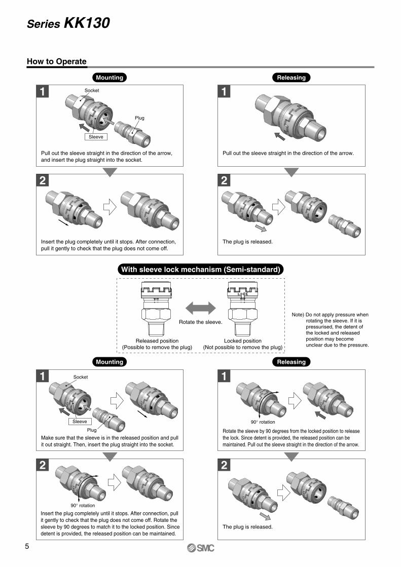
How to Operate
Mounting
With sleeve lock mechanism (Semi-standard)
Releasing
Mounting Releasing
Pull out the sleeve straight in the direction of the arrow, and insert the plug straight into the socket.
Insert the plug completely until it stops. After connection, pull it gently to check that the plug does not come off.
Pull out the sleeve straight in the direction of the arrow.
The plug is released.
Make sure that the sleeve is in the released position and pull it out straight. Then, insert the plug straight into the socket.
Insert the plug completely until it stops. After connection, pull it gently to check that the plug does not come off. Rotate the sleeve by 90 degrees to match it to the locked position. Since detent is provided, the released position can be maintained.
Rotate the sleeve by 90 degrees from the locked position to release the lock. Since detent is provided, the released position can be maintained. Pull out the sleeve straight in the direction of the arrow.
The plug is released.
Rotate the sleeve.
Released position(Possible to remove the plug)
Locked position(Not possible to remove the plug)
Note) Do not apply pressure when rotating the sleeve. If it is pressurised, the detent of the locked and released position may become unclear due to the pressure.
Series KK130
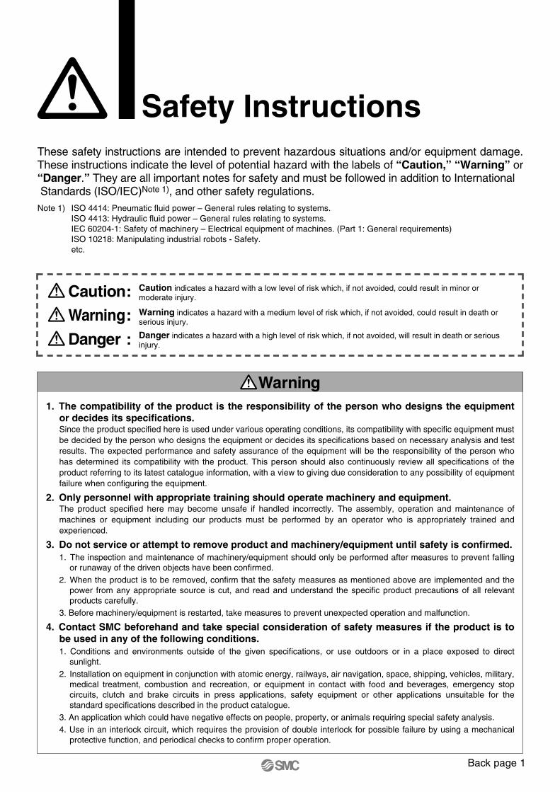
Safety InstructionsThese safety instructions are intended to prevent hazardous situations and/or equipment damage. These instructions indicate the level of potential hazard with the labels of “Caution,” “Warning” or “Danger.” They are all important notes for safety and must be followed in addition to International Standards (ISO/IEC)Note 1), and other safety regulations.Note 1) ISO 4414: Pneumatic fluid power – General rules relating to systems.
ISO 4413: Hydraulic fluid power – General rules relating to systems.IEC 60204-1: Safety of machinery – Electrical equipment of machines. (Part 1: General requirements)ISO 10218: Manipulating industrial robots - Safety.etc.
1. The compatibility of the product is the responsibility of the person who designs the equipment or decides its specifications.Since the product specified here is used under various operating conditions, its compatibility with specific equipment must be decided by the person who designs the equipment or decides its specifications based on necessary analysis and test results. The expected performance and safety assurance of the equipment will be the responsibility of the person who has determined its compatibility with the product. This person should also continuously review all specifications of the product referring to its latest catalogue information, with a view to giving due consideration to any possibility of equipment failure when configuring the equipment.
2. Only personnel with appropriate training should operate machinery and equipment.The product specified here may become unsafe if handled incorrectly. The assembly, operation and maintenance of machines or equipment including our products must be performed by an operator who is appropriately trained and experienced.
3. Do not service or attempt to remove product and machinery/equipment until safety is confirmed.1. The inspection and maintenance of machinery/equipment should only be performed after measures to prevent falling
or runaway of the driven objects have been confirmed. 2. When the product is to be removed, confirm that the safety measures as mentioned above are implemented and the
power from any appropriate source is cut, and read and understand the specific product precautions of all relevant products carefully.
3. Before machinery/equipment is restarted, take measures to prevent unexpected operation and malfunction.
4. Contact SMC beforehand and take special consideration of safety measures if the product is to be used in any of the following conditions. 1. Conditions and environments outside of the given specifications, or use outdoors or in a place exposed to direct
sunlight.2. Installation on equipment in conjunction with atomic energy, railways, air navigation, space, shipping, vehicles, military,
medical treatment, combustion and recreation, or equipment in contact with food and beverages, emergency stop circuits, clutch and brake circuits in press applications, safety equipment or other applications unsuitable for the standard specifications described in the product catalogue.
3. An application which could have negative effects on people, property, or animals requiring special safety analysis. 4. Use in an interlock circuit, which requires the provision of double interlock for possible failure by using a mechanical
protective function, and periodical checks to confirm proper operation.
Warning
Caution:
Danger :
Warning:
Caution indicates a hazard with a low level of risk which, if not avoided, could result in minor or moderate injury.
Danger indicates a hazard with a high level of risk which, if not avoided, will result in death or serious injury.
Warning indicates a hazard with a medium level of risk which, if not avoided, could result in death or serious injury.
5
Safety InstructionsThese safety instructions are intended to prevent hazardous situations and/or equipment damage. These instructions indicate the level of potential hazard with the labels of “Caution,” “Warning” or “Danger.” They are all important notes for safety and must be followed in addition to International Standards (ISO/IEC)Note 1), and other safety regulations.Note 1) ISO 4414: Pneumatic fluid power – General rules relating to systems.
ISO 4413: Hydraulic fluid power – General rules relating to systems.IEC 60204-1: Safety of machinery – Electrical equipment of machines. (Part 1: General requirements)ISO 10218: Manipulating industrial robots - Safety.etc.
1. The compatibility of the product is the responsibility of the person who designs the equipment or decides its specifications.Since the product specified here is used under various operating conditions, its compatibility with specific equipment must be decided by the person who designs the equipment or decides its specifications based on necessary analysis and test results. The expected performance and safety assurance of the equipment will be the responsibility of the person who has determined its compatibility with the product. This person should also continuously review all specifications of the product referring to its latest catalogue information, with a view to giving due consideration to any possibility of equipment failure when configuring the equipment.
2. Only personnel with appropriate training should operate machinery and equipment.The product specified here may become unsafe if handled incorrectly. The assembly, operation and maintenance of machines or equipment including our products must be performed by an operator who is appropriately trained and experienced.
3. Do not service or attempt to remove product and machinery/equipment until safety is confirmed.1. The inspection and maintenance of machinery/equipment should only be performed after measures to prevent falling
or runaway of the driven objects have been confirmed. 2. When the product is to be removed, confirm that the safety measures as mentioned above are implemented and the
power from any appropriate source is cut, and read and understand the specific product precautions of all relevant products carefully.
3. Before machinery/equipment is restarted, take measures to prevent unexpected operation and malfunction.
4. Contact SMC beforehand and take special consideration of safety measures if the product is to be used in any of the following conditions. 1. Conditions and environments outside of the given specifications, or use outdoors or in a place exposed to direct
sunlight.2. Installation on equipment in conjunction with atomic energy, railways, air navigation, space, shipping, vehicles, military,
medical treatment, combustion and recreation, or equipment in contact with food and beverages, emergency stop circuits, clutch and brake circuits in press applications, safety equipment or other applications unsuitable for the standard specifications described in the product catalogue.
3. An application which could have negative effects on people, property, or animals requiring special safety analysis. 4. Use in an interlock circuit, which requires the provision of double interlock for possible failure by using a mechanical
protective function, and periodical checks to confirm proper operation.
Warning
Caution:
Danger :
Warning:
Caution indicates a hazard with a low level of risk which, if not avoided, could result in minor or moderate injury.
Danger indicates a hazard with a high level of risk which, if not avoided, will result in death or serious injury.
Warning indicates a hazard with a medium level of risk which, if not avoided, could result in death or serious injury.
Back page 1

Safety Instructions
Limited warranty and Disclaimer/Compliance Requirements The product used is subject to the following “Limited warranty and Disclaimer” and “Compliance Requirements”.Read and accept them before using the product.
1. The product is provided for use in manufacturing industries.The product herein described is basically provided for peaceful use in manufacturing industries. If considering using the product in other industries, consult SMC beforehand and exchange specifications or a contract if necessary. If anything is unclear, contact your nearest sales branch.
Caution
Limited warranty and Disclaimer
1. The warranty period of the product is 1 year in service or 1.5 years after the product is delivered.Note 2)
Also, the product may have specified durability, running distance or replacement parts. Please consult your nearest sales branch.
2. For any failure or damage reported within the warranty period which is clearly our responsibility, a replacement product or necessary parts will be provided. This limited warranty applies only to our product independently, and not to any other damage incurred due to the failure of the product.
3. Prior to using SMC products, please read and understand the warranty terms and disclaimers noted in the specified catalogue for the particular products.
Note 2) Vacuum pads are excluded from this 1 year warranty.A vacuum pad is a consumable part, so it is warranted for a year after it is delivered. Also, even within the warranty period, the wear of a product due to the use of the vacuum pad or failure due to the deterioration of rubber material are not covered by the limited warranty.
Compliance Requirements1. The use of SMC products with production equipment for the manufacture of weapons of mass destruction (WMD) or
any other weapon is strictly prohibited.
2. The exports of SMC products or technology from one country to another are governed by the relevant security laws and regulations of the countries involved in the transaction. Prior to the shipment of a SMC product to another country, assure that all local rules governing that export are known and followed.
KK13KK130
Series KK KKH KKA KKG KK130
—
—
—
—
—
—
—
—
KK13
η =L – D
2d1– x 100
Here, η : Deformation ratio (%)d : Tube O.D. (mm)L : Measured length (mm)D: Mandrel diameter (mm)
(Twice against the minimum bending radius)
Test temperature: 20 ±5°CRelative humidity: 65 ±5%
Tube deformation ratio at theminimum bending radius
Mandrel
Series KK130Specific Product Precautions 1Be sure to read before handling.Refer to back pages 1 and 2 for Safety Instructions, “Handling Precautions for SMC Products” (M-E03-3) for Fittings and Tubing Precautions.
Selection
Warning1. Make sure to confirm the specifications.
Do not use with pressures or temperatures outside the range of specifications, as this may result in damage and malfunc-tion. (Refer to the specifications on page 1.) SMC takes no responsibility for damage incurred by use in excess of the specification range.
2. Prohibition of disassembly and modificationDo not disassemble or modify (including additional machining) the main body. False use may cause an injury or accident.
3. Confirm that PTFE can be used in application.Thread sealant contains PTFE (polytetrafluoroethylene) pow-der. Confirm if the use of it may cause any adverse effect on the system.
4. Cannot be used as a stop valve that requires zero leakage.A certain amount of leakage is allowed during operation.
5. Refer to the table below for whether the S coupler can be connected.
When the KK130 series is connected to other companies’ pro-ducts, confirm manufacturers and other information before using it.
Caution1. When connecting the plug to the socket, select the
series suitable for the connection.If the series are not matched, they cannot be connected. Mis-matches will cause leakage, damage, and disconnection of the plug. Inserting a plug other than the specialised plug into the socket may result in equipment damage.
2. Do not rotate or turn the S coupler and piping to which it is connected.The connection of the piping might be damaged or come un-done.
3. Do not use couplers with flammable, explosive, or toxic substances, such as gas, gas fuel, and refri-gerant. They may leak from the S coupler or from inside the tubing to the outside.
4. Operate with a surge pressure of no more than the maximum operating pressure.If the surge pressure exceeds the maximum operating pressu-re, it will cause damage to couplers and tubing.
5. Do not use the S coupler with water or steam.Corrosion of the metal material and deterioration of the sea-ling material may result from long-term use with water or steam.
6. The tube bending radius in the vicinity of the fitting should be at least the minimum bending radius of the tube.If the bending radius is less than the minimum value, fittings may damage, or tube may crack or be crushed. The minimum bending radius, with the exception of TU polyurethane tube, TUH hard polyurethane tube, TUS soft polyurethane tube, TRBU FR double layer polyurethane tube, TH FEP tube, TL PFA tube, TD modified PTFE tube, is measured as following in accordance with JIS B 8381-1995.Tube deformation ratio at the minimum bending radius is ob-tained through the following formula, based on tube diameter and mandrel diameter by wrapping the same radius mandrel tube.
7. Applicable for air.Consult with SMC if using other fluids.
1. Instruction manualMount and operate the product after reading the instruction manual carefully and understanding its contents. Also, keep the manual where it can be referred to as necessary.
2. Ensure sufficient space for maintenance.Be sure to allow the space required for maintenance and ins-pection.
3. Tightening torqueWhen installing the products, tighten the screw with the re-commended tightening torque.
4. During use, pipe deterioration or damage to S cou-plers can result in disconnection of the piping and uncontrollable behavior of the piping.To stop the piping from going out of control, use a protective cover or fix the piping in place.
5. Do not use couplers where rotation normally oc-curs.The couplers may be damaged.
6. Avoid applications in which vibration or shock is directly applied to the fittings.When mounting the S coupler to a piece of equipment that generates impact or vibration, do not connect the S coupler to the equipment directly. In that case, connect a hose whose length is 300 mm or more between the S couplers.
Mounting
Warning
Back page 2

Safety Instructions
Limited warranty and Disclaimer/Compliance Requirements The product used is subject to the following “Limited warranty and Disclaimer” and “Compliance Requirements”.Read and accept them before using the product.
1. The product is provided for use in manufacturing industries.The product herein described is basically provided for peaceful use in manufacturing industries. If considering using the product in other industries, consult SMC beforehand and exchange specifications or a contract if necessary. If anything is unclear, contact your nearest sales branch.
Caution
Limited warranty and Disclaimer
1. The warranty period of the product is 1 year in service or 1.5 years after the product is delivered.Note 2)
Also, the product may have specified durability, running distance or replacement parts. Please consult your nearest sales branch.
2. For any failure or damage reported within the warranty period which is clearly our responsibility, a replacement product or necessary parts will be provided. This limited warranty applies only to our product independently, and not to any other damage incurred due to the failure of the product.
3. Prior to using SMC products, please read and understand the warranty terms and disclaimers noted in the specified catalogue for the particular products.
Note 2) Vacuum pads are excluded from this 1 year warranty.A vacuum pad is a consumable part, so it is warranted for a year after it is delivered. Also, even within the warranty period, the wear of a product due to the use of the vacuum pad or failure due to the deterioration of rubber material are not covered by the limited warranty.
Compliance Requirements1. The use of SMC products with production equipment for the manufacture of weapons of mass destruction (WMD) or
any other weapon is strictly prohibited.
2. The exports of SMC products or technology from one country to another are governed by the relevant security laws and regulations of the countries involved in the transaction. Prior to the shipment of a SMC product to another country, assure that all local rules governing that export are known and followed.
KK13KK130
Series KK KKH KKA KKG KK130
—
—
—
—
—
—
—
—
KK13
η =L – D
2d1– x 100
Here, η : Deformation ratio (%)d : Tube O.D. (mm)L : Measured length (mm)D: Mandrel diameter (mm)
(Twice against the minimum bending radius)
Test temperature: 20 ±5°CRelative humidity: 65 ±5%
Tube deformation ratio at theminimum bending radius
Mandrel
Series KK130Specific Product Precautions 1Be sure to read before handling.Refer to back pages 1 and 2 for Safety Instructions, “Handling Precautions for SMC Products” (M-E03-3) for Fittings and Tubing Precautions.
Selection
Warning1. Make sure to confirm the specifications.
Do not use with pressures or temperatures outside the range of specifications, as this may result in damage and malfunc-tion. (Refer to the specifications on page 1.) SMC takes no responsibility for damage incurred by use in excess of the specification range.
2. Prohibition of disassembly and modificationDo not disassemble or modify (including additional machining) the main body. False use may cause an injury or accident.
3. Confirm that PTFE can be used in application.Thread sealant contains PTFE (polytetrafluoroethylene) pow-der. Confirm if the use of it may cause any adverse effect on the system.
4. Cannot be used as a stop valve that requires zero leakage.A certain amount of leakage is allowed during operation.
5. Refer to the table below for whether the S coupler can be connected.
When the KK130 series is connected to other companies’ pro-ducts, confirm manufacturers and other information before using it.
Caution1. When connecting the plug to the socket, select the
series suitable for the connection.If the series are not matched, they cannot be connected. Mis-matches will cause leakage, damage, and disconnection of the plug. Inserting a plug other than the specialised plug into the socket may result in equipment damage.
2. Do not rotate or turn the S coupler and piping to which it is connected.The connection of the piping might be damaged or come un-done.
3. Do not use couplers with flammable, explosive, or toxic substances, such as gas, gas fuel, and refri-gerant. They may leak from the S coupler or from inside the tubing to the outside.
4. Operate with a surge pressure of no more than the maximum operating pressure.If the surge pressure exceeds the maximum operating pressu-re, it will cause damage to couplers and tubing.
5. Do not use the S coupler with water or steam.Corrosion of the metal material and deterioration of the sea-ling material may result from long-term use with water or steam.
6. The tube bending radius in the vicinity of the fitting should be at least the minimum bending radius of the tube.If the bending radius is less than the minimum value, fittings may damage, or tube may crack or be crushed. The minimum bending radius, with the exception of TU polyurethane tube, TUH hard polyurethane tube, TUS soft polyurethane tube, TRBU FR double layer polyurethane tube, TH FEP tube, TL PFA tube, TD modified PTFE tube, is measured as following in accordance with JIS B 8381-1995.Tube deformation ratio at the minimum bending radius is ob-tained through the following formula, based on tube diameter and mandrel diameter by wrapping the same radius mandrel tube.
7. Applicable for air.Consult with SMC if using other fluids.
1. Instruction manualMount and operate the product after reading the instruction manual carefully and understanding its contents. Also, keep the manual where it can be referred to as necessary.
2. Ensure sufficient space for maintenance.Be sure to allow the space required for maintenance and ins-pection.
3. Tightening torqueWhen installing the products, tighten the screw with the re-commended tightening torque.
4. During use, pipe deterioration or damage to S cou-plers can result in disconnection of the piping and uncontrollable behavior of the piping.To stop the piping from going out of control, use a protective cover or fix the piping in place.
5. Do not use couplers where rotation normally oc-curs.The couplers may be damaged.
6. Avoid applications in which vibration or shock is directly applied to the fittings.When mounting the S coupler to a piece of equipment that generates impact or vibration, do not connect the S coupler to the equipment directly. In that case, connect a hose whose length is 300 mm or more between the S couplers.
Mounting
Warning
Back page 3
Air Supply
1. Do not use in atmospheres of corrosive gases, che-micals, sea water, water, water steam, or where the-re is direct contact with any of these.
2. Do not use in direct sunlight.3. In locations near heat sources, protect against ra-
diated heat.4. Do not use in locations where static electric char-
ges will be a problem.This may cause system failure. Consult with SMC regarding use in this kind of environment.
5. Do not use in locations where spatter occurs.There is a danger of spatter causing a fire. Consult with SMC regarding use in this kind of environment.
6. Do not use in environments where there is direct contact with liquids such as cutting oil, lubricating oil, coolant oil, or paints, etc.This may cause connection and release failure and/or leaka-ge. Consult with SMC regarding use in this kind of environ-ment.
7. Do not use in locations influenced by vibrations or impacts.This may cause air leakage and S couplers damage. Consult with SMC regarding use in this kind of environment.
8. Do not use in an environment where foreign matter such as spatter, metal powder or sand splashes on-to or enters the product.This may cause connection and release failure and/or leaka-ge.
9. Do not use in an environment where the product is constantly exposed to water.Rust may occur.
10. When the socket and plug are stored or not in use, make sure dust does not get stuck to them. This may cause connection and release failure and/or leaka-ge.
Operating Environment
Warning
1. Install an air filter.Install an air filter upstream, near the valve. Select an air filter with a filtration degree of 5 µm or finer.
2. As a countermeasure, install an aftercooler, air dryer or water separator.Compressed air containing large amounts of drainage can cause malfunction of pneumatic equipment. As a counter-measure, install an aftercooler, air dryer or water separator.
3. Ensure that the fluid and ambient temperature are within the specified range.If the fluid temperature is 5°C or below, the moisture in the cir-cuit could freeze, causing damage to the seals and leading to equipment malfunction. Therefore, take appropriate measures to prevent freezing.
Refer to SMC's “Air Preparation Equipment” catalogue for further details on compressed air quality.
Caution
1. Excessive drainageCompressed air containing large amounts of drainage can cau-se malfunction of pneumatic equipment. As a counter-measure, install an air dryer or water separator before the filter.
2. Drain flushingIf the drain removal from air filter is missed, drain will be flown out to the outlet side and may result in malfunction of pneu-matic equipment. When removing drain is difficult, use of a fil-ter with an auto drain is recommended.
Refer to SMC's “Air Preparation Equipment” catalogue for further details on compressed air quality.
3. Use clean air.If the compressed air includes chemicals, synthetic oils contai-ning organic solvents, salt or corrosive gases, etc., it can cau-se damage or malfunction in the system.
Air Supply
Warning
Wrapping direction
Pipe tape
Leave approximately
one length of screw
exposed.
7. S couplers with sleeve lock mechanism must be lo-cked during operation in order to prevent sudden disconnection.
8. Install a stop valve at the supply pressure side of the socket.Emergency shutdown may not be possible without it.
Mounting
Warning
1. Preparation before pipingBefore piping is connected, it should be thoroughly blown out by air (flushed) or washed to eliminate cutting chips, cutting oil, and other debris from inside the pipe.
2. Before mounting, confirm the model and size, etc.Also, confirm that there are no blemishes, nicks or cracks in the product.
3. When connecting a pipe, consider factors such as changes in the piping length due to pressure, and allow sufficient leeway.
4. Mount so that S couplers and piping are not subjec-ted to twisting, pulling or moment loads.This can cause damage to S couplers and flattening, bursting or disconnection of piping, etc.
5. Mount so that piping is not damaged due to tan-gling and abrasion.This can cause flattening, bursting or disconnection of piping, etc.
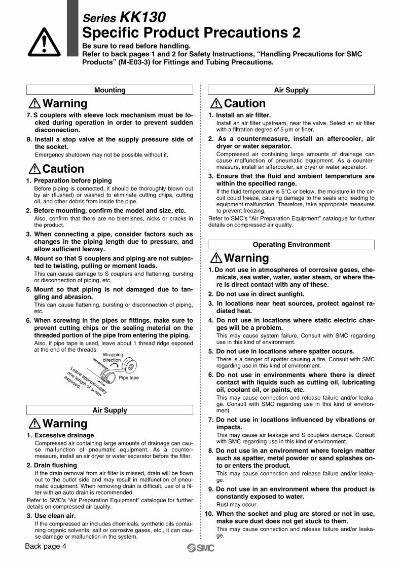
6. When screwing in the pipes or fittings, make sure to prevent cutting chips or the sealing material on the threaded portion of the pipe from entering the piping.Also, if pipe tape is used, leave about 1 thread ridge exposed at the end of the threads.
Caution
Series KK130Specific Product Precautions 2Be sure to read before handling.Refer to back pages 1 and 2 for Safety Instructions, “Handling Precautions for SMC Products” (M-E03-3) for Fittings and Tubing Precautions.
1. When connecting the plug, hold the plug securely. The plug may be uncoupled due to reaction at the time of con-nection.
2. When connecting the plug, pull out the sleeve straight and insert the plug completely until it stops.After the connection, gently pull the plug to see whether it will release. If not securely inserted, the plug may pop out due to the pressure.
3. When connecting the plug, insert it straight into the socket.If not inserted straight, the socket and/or plug may be dama-ged or cause a disconnection.
4. When releasing the plug, hold it securely.When releasing the plug, hold it securely. The connection pipe may go out of control due to reacting stress and/or residual pressure on the plug side.
5. Do not press the inside of the socket with an incom-patible plug and/or with a tool.The internal fluid may be ejected and cause a dangerous si-tuation. Also, the ejecting internal fluid may cause the sealings to come apart resulting in the product not functioning.
6. Do not connect and remove the coupler when it is pressurised and residual pressure exists.The coupler may fly out.
7. Do not apply lateral load vertically to the connec-tion direction of the plug or socket.This may cause leakage and damage the coupler.
8. Never pressurise when the plug is removed.This may cause the connection piping to flap and be dange-rous.
9. When removing the plug, fluid in the piping leaks out.Handle the fluid carefully, especially when using dangerous fluids such as a fluid with high temperature and pressure. The use of a stop valve is recommended.
10. When using a fluid with high temperature, the S coupler will be heated, too.Do not touch the coupler to prevent burning.
11. When sleeve lock mechanism is provided, do not apply pressure when rotating the sleeve.If it is pressurised, the detent of the locked and released posi-tion may become unclear due to the pressure.
12. Do not disassemble the S coupler.
Handling
Warning11. Do not use in places or environments where fo-
reign matter sticks to the product or gets inside the product.It may cause air leakage or tube release.
Operating Environment
Warning
1. Maintenance workIf handled improperly, compressed air can be dangerous. As-sembly, handling, repair and element replacement of pneuma-tic systems should be performed by qualified personnel only.
2. Drain flushingRemove drainage from air filters regularly.
3. Removal of equipment, and supply/exhaust of com-pressed airWhen components are removed, first confirm that measures are in place to prevent workpieces from dropping, run-away equipment, etc. Then, cut the supply pressure and power, and exhaust all compressed air from the system using the residual pressure release function.When machinery is restarted, proceed with caution after con-firming that appropriate measures are in place to prevent cylinders from sudden movement.
4. Be absolutely sure to wear safety glasses when conducting periodic inspections.
5. Check for the following during regular maintenance, and replace components as necessary.a) Scratches, gouges, abrasion, corrosion, rustb) Leakagec) Twisting, flattening or distortion of tubes and hosesd) Hardening, deterioration or softening
6. Do not repair or patch the replaced tubing, hoses or couplers for reuse.Do not disassemble the S coupler.
Maintenance
Caution
Series KK130Specific Product Precautions 3Be sure to read before handling.Refer to back pages 1 and 2 for Safety Instructions, “Handling Precautions for SMC Products” (M-E03-3) for Fittings and Tubing Precautions.
Back page 4
Air Supply
1. Do not use in atmospheres of corrosive gases, che-micals, sea water, water, water steam, or where the-re is direct contact with any of these.
2. Do not use in direct sunlight.3. In locations near heat sources, protect against ra-
diated heat.4. Do not use in locations where static electric char-
ges will be a problem.This may cause system failure. Consult with SMC regarding use in this kind of environment.
5. Do not use in locations where spatter occurs.There is a danger of spatter causing a fire. Consult with SMC regarding use in this kind of environment.
6. Do not use in environments where there is direct contact with liquids such as cutting oil, lubricating oil, coolant oil, or paints, etc.This may cause connection and release failure and/or leaka-ge. Consult with SMC regarding use in this kind of environ-ment.
7. Do not use in locations influenced by vibrations or impacts.This may cause air leakage and S couplers damage. Consult with SMC regarding use in this kind of environment.
8. Do not use in an environment where foreign matter such as spatter, metal powder or sand splashes on-to or enters the product.This may cause connection and release failure and/or leaka-ge.
9. Do not use in an environment where the product is constantly exposed to water.Rust may occur.
10. When the socket and plug are stored or not in use, make sure dust does not get stuck to them. This may cause connection and release failure and/or leaka-ge.
Operating Environment
Warning
1. Install an air filter.Install an air filter upstream, near the valve. Select an air filter with a filtration degree of 5 µm or finer.
2. As a countermeasure, install an aftercooler, air dryer or water separator.Compressed air containing large amounts of drainage can cause malfunction of pneumatic equipment. As a counter-measure, install an aftercooler, air dryer or water separator.
3. Ensure that the fluid and ambient temperature are within the specified range.If the fluid temperature is 5°C or below, the moisture in the cir-cuit could freeze, causing damage to the seals and leading to equipment malfunction. Therefore, take appropriate measures to prevent freezing.
Refer to SMC's “Air Preparation Equipment” catalogue for further details on compressed air quality.
Caution
1. Excessive drainageCompressed air containing large amounts of drainage can cau-se malfunction of pneumatic equipment. As a counter-measure, install an air dryer or water separator before the filter.
2. Drain flushingIf the drain removal from air filter is missed, drain will be flown out to the outlet side and may result in malfunction of pneu-matic equipment. When removing drain is difficult, use of a fil-ter with an auto drain is recommended.
Refer to SMC's “Air Preparation Equipment” catalogue for further details on compressed air quality.
3. Use clean air.If the compressed air includes chemicals, synthetic oils contai-ning organic solvents, salt or corrosive gases, etc., it can cau-se damage or malfunction in the system.
Air Supply
Warning
Wrapping direction
Pipe tape
Leave approximately
one length of screw
exposed.
7. S couplers with sleeve lock mechanism must be lo-cked during operation in order to prevent sudden disconnection.
8. Install a stop valve at the supply pressure side of the socket.Emergency shutdown may not be possible without it.
Mounting
Warning
1. Preparation before pipingBefore piping is connected, it should be thoroughly blown out by air (flushed) or washed to eliminate cutting chips, cutting oil, and other debris from inside the pipe.
2. Before mounting, confirm the model and size, etc.Also, confirm that there are no blemishes, nicks or cracks in the product.
3. When connecting a pipe, consider factors such as changes in the piping length due to pressure, and allow sufficient leeway.
4. Mount so that S couplers and piping are not subjec-ted to twisting, pulling or moment loads.This can cause damage to S couplers and flattening, bursting or disconnection of piping, etc.
5. Mount so that piping is not damaged due to tan-gling and abrasion.This can cause flattening, bursting or disconnection of piping, etc.
6. When screwing in the pipes or fittings, make sure to prevent cutting chips or the sealing material on the threaded portion of the pipe from entering the piping.Also, if pipe tape is used, leave about 1 thread ridge exposed at the end of the threads.
Caution
Series KK130Specific Product Precautions 2Be sure to read before handling.Refer to back pages 1 and 2 for Safety Instructions, “Handling Precautions for SMC Products” (M-E03-3) for Fittings and Tubing Precautions.
1. When connecting the plug, hold the plug securely. The plug may be uncoupled due to reaction at the time of con-nection.
2. When connecting the plug, pull out the sleeve straight and insert the plug completely until it stops.After the connection, gently pull the plug to see whether it will release. If not securely inserted, the plug may pop out due to the pressure.
3. When connecting the plug, insert it straight into the socket.If not inserted straight, the socket and/or plug may be dama-ged or cause a disconnection.
4. When releasing the plug, hold it securely.When releasing the plug, hold it securely. The connection pipe may go out of control due to reacting stress and/or residual pressure on the plug side.
5. Do not press the inside of the socket with an incom-patible plug and/or with a tool.The internal fluid may be ejected and cause a dangerous si-tuation. Also, the ejecting internal fluid may cause the sealings to come apart resulting in the product not functioning.
6. Do not connect and remove the coupler when it is pressurised and residual pressure exists.The coupler may fly out.
7. Do not apply lateral load vertically to the connec-tion direction of the plug or socket.This may cause leakage and damage the coupler.
8. Never pressurise when the plug is removed.This may cause the connection piping to flap and be dange-rous.
9. When removing the plug, fluid in the piping leaks out.Handle the fluid carefully, especially when using dangerous fluids such as a fluid with high temperature and pressure. The use of a stop valve is recommended.
10. When using a fluid with high temperature, the S coupler will be heated, too.Do not touch the coupler to prevent burning.
11. When sleeve lock mechanism is provided, do not apply pressure when rotating the sleeve.If it is pressurised, the detent of the locked and released posi-tion may become unclear due to the pressure.
12. Do not disassemble the S coupler.
Handling
Warning11. Do not use in places or environments where fo-
reign matter sticks to the product or gets inside the product.It may cause air leakage or tube release.
Operating Environment
Warning
1. Maintenance workIf handled improperly, compressed air can be dangerous. As-sembly, handling, repair and element replacement of pneuma-tic systems should be performed by qualified personnel only.
2. Drain flushingRemove drainage from air filters regularly.
3. Removal of equipment, and supply/exhaust of com-pressed airWhen components are removed, first confirm that measures are in place to prevent workpieces from dropping, run-away equipment, etc. Then, cut the supply pressure and power, and exhaust all compressed air from the system using the residual pressure release function.When machinery is restarted, proceed with caution after con-firming that appropriate measures are in place to prevent cylinders from sudden movement.
4. Be absolutely sure to wear safety glasses when conducting periodic inspections.
5. Check for the following during regular maintenance, and replace components as necessary.a) Scratches, gouges, abrasion, corrosion, rustb) Leakagec) Twisting, flattening or distortion of tubes and hosesd) Hardening, deterioration or softening
6. Do not repair or patch the replaced tubing, hoses or couplers for reuse.Do not disassemble the S coupler.
Maintenance
Caution
Series KK130Specific Product Precautions 3Be sure to read before handling.Refer to back pages 1 and 2 for Safety Instructions, “Handling Precautions for SMC Products” (M-E03-3) for Fittings and Tubing Precautions.
Back page 5

200
150
100
50
00
Charging pressure MPa0.5 1.5
Inse
rtio
n fo
rce
N
1
1. Screw the fitting into the hexagonal face of the S coupler, applying the appropriate wrench as close to the thread as possible.Place the wrench as close as possible to the thread. Do not apply pliers and pipe wrench to any other part other than the wrench flats. This may cause breakage or leakage.
2. Tightening torqueTighten fittings with sealant using the proper tightening tor-ques in the table below. As a rule, they should be tightened 2 to 3 turns with a tool after first tightening by hand.
Handling of Thread Type
Caution
Plug Insertion Force in Pressurised Condition
Insertion Force of Series KK130
3. When a fitting is over tightened, more of the sealant material is squeezed out.Remove the squeezed out sealant material.
4. When tightening is not sufficient, it will cause sea-ling failure or a loose fitting.
5. Re-using1) Normally, a fitting with sealant can be re-used 2 to 3 times.2) Remove the sealant material that is separated and adhe-
ring to a removed fitting with air blow, etc. If the separated sealant enters into nearby equipment, it will cause air lea-kage or malfunction.
3) When the sealant is no longer effective, wrap pipe tape over the sealant material and re-use the fitting. Do not use a sealant material other than pipe tape.
6. In cases where positioning is required, turning the fitting in the reverse direction after tightening will cause air leakage.
Connection thread size
NPT, R, Rc1/8
NPT, R, Rc1/4
NPT, R, Rc3/8
NPT, R, Rc1/2
Proper tightening torque N·m
7 to 9
12 to 14
22 to 24
28 to 30
1. Prepare a hose band separately when using a barb fitting.If the hose band is not used, the hose may come off.
2. When using a nut fitting, insert the hose all the way to the end and securely tighten it with the nut.When the insertion of the hose or the tightening of the nut are not sufficient, the hose may come off.
3. Disconnection may occur depending on the mate-rial or the O.D. accuracy of the hose; therefore be sure to confirm the applicability of the hose.
Handling of Barb Fittings and Nut Fittings
Caution
Series KK130Specific Product Precautions 4Be sure to read before handling.Refer to back pages 1 and 2 for Safety Instructions, “Handling Precautions for SMC Products” (M-E03-3) for Fittings and Tubing Precautions.
Straight section
Mounting pitch A
Fig. 1 Recommended piping
Fig. 2 When using a unifying band to bind together the pipes
Recommended NG
1. When using tubing brands other than SMC, confirm that the tube outside diameter tolerances satisfy the following specifications.1) Nylon tube within ±0.1 mm2) Soft nylon tube within ±0.1 mm3) Polyurethane tube within +0.15 mm, within –0.2 mmIf the tube O.D. accuracy is satisfactory but measurement of the internal diameter dimensions does not match the dimen-sions provided by SMC, do not use. The tube may not connect, or leaks, tube disconnection, or damage to fittings may occur.
Precautions on Other Tubing Brands
Caution
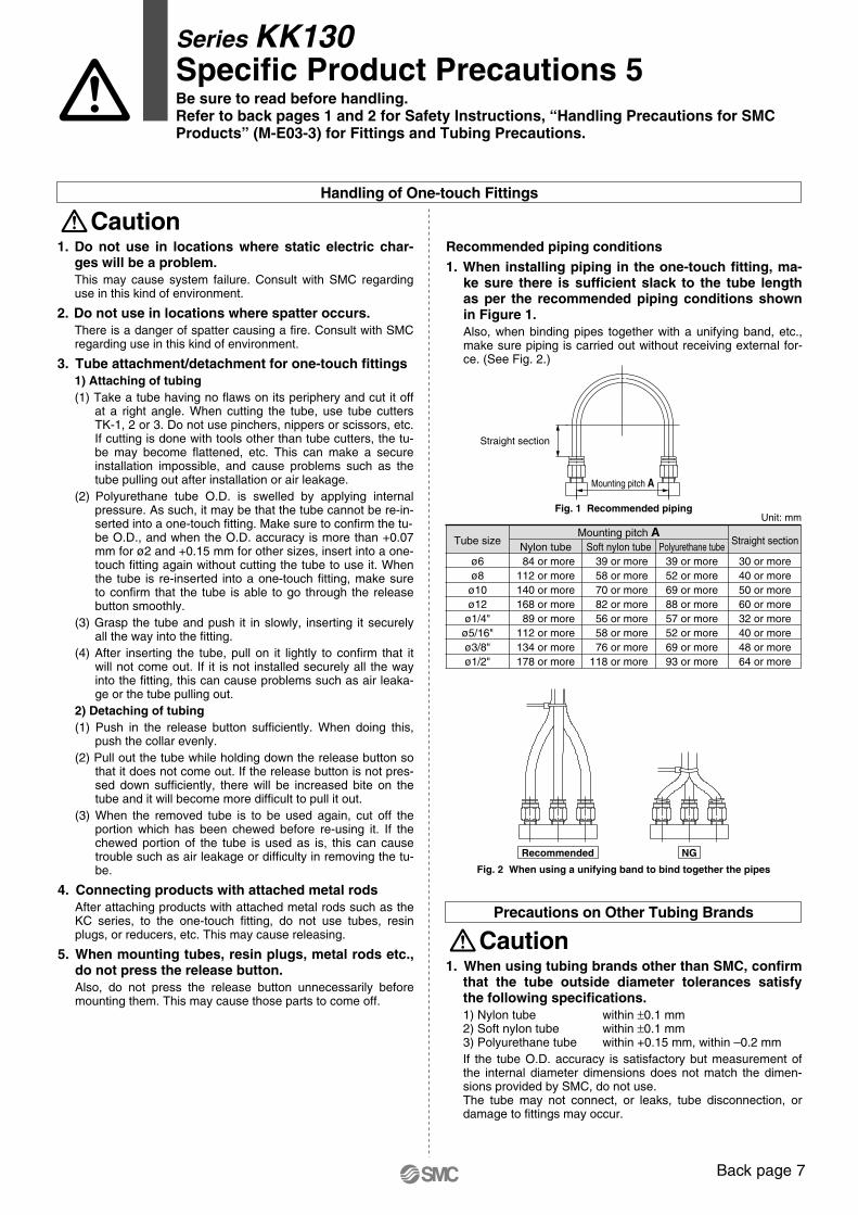
Recommended piping conditions1. When installing piping in the one-touch fitting, ma-
ke sure there is sufficient slack to the tube length as per the recommended piping conditions shown in Figure 1.Also, when binding pipes together with a unifying band, etc., make sure piping is carried out without receiving external for-ce. (See Fig. 2.)
Tube sizeMounting pitch A
Unit: mm
Nylon tube Soft nylon tube Polyurethane tube84 or more
112 or more140 or more168 or more89 or more
112 or more134 or more178 or more
39 or more58 or more70 or more82 or more56 or more58 or more76 or more
118 or more
39 or more52 or more69 or more88 or more57 or more52 or more69 or more93 or more
Straight section
ø6ø8
ø10ø12
ø1/4"ø5/16"ø3/8"ø1/2"
30 or more40 or more50 or more60 or more32 or more40 or more48 or more64 or more
1. Do not use in locations where static electric char-ges will be a problem.This may cause system failure. Consult with SMC regarding use in this kind of environment.
2. Do not use in locations where spatter occurs.There is a danger of spatter causing a fire. Consult with SMC regarding use in this kind of environment.
3. Tube attachment/detachment for one-touch fittings1) Attaching of tubing(1) Take a tube having no flaws on its periphery and cut it off
at a right angle. When cutting the tube, use tube cutters TK-1, 2 or 3. Do not use pinchers, nippers or scissors, etc. If cutting is done with tools other than tube cutters, the tu-be may become flattened, etc. This can make a secure installation impossible, and cause problems such as the tube pulling out after installation or air leakage.
(2) Polyurethane tube O.D. is swelled by applying internal pressure. As such, it may be that the tube cannot be re-in-serted into a one-touch fitting. Make sure to confirm the tu-be O.D., and when the O.D. accuracy is more than +0.07 mm for ø2 and +0.15 mm for other sizes, insert into a one-touch fitting again without cutting the tube to use it. When the tube is re-inserted into a one-touch fitting, make sure to confirm that the tube is able to go through the release button smoothly.
(3) Grasp the tube and push it in slowly, inserting it securely all the way into the fitting.
(4) After inserting the tube, pull on it lightly to confirm that it will not come out. If it is not installed securely all the way into the fitting, this can cause problems such as air leaka-ge or the tube pulling out.
2) Detaching of tubing(1) Push in the release button sufficiently. When doing this,
push the collar evenly.(2) Pull out the tube while holding down the release button so
that it does not come out. If the release button is not pres-sed down sufficiently, there will be increased bite on the tube and it will become more difficult to pull it out.
(3) When the removed tube is to be used again, cut off the portion which has been chewed before re-using it. If the chewed portion of the tube is used as is, this can cause trouble such as air leakage or difficulty in removing the tu-be.
4. Connecting products with attached metal rodsAfter attaching products with attached metal rods such as the KC series, to the one-touch fitting, do not use tubes, resin plugs, or reducers, etc. This may cause releasing.
5. When mounting tubes, resin plugs, metal rods etc., do not press the release button.Also, do not press the release button unnecessarily before mounting them. This may cause those parts to come off.
Handling of One-touch Fittings
Caution
Series KK130Specific Product Precautions 5Be sure to read before handling.Refer to back pages 1 and 2 for Safety Instructions, “Handling Precautions for SMC Products” (M-E03-3) for Fittings and Tubing Precautions.
Back page 6
200
150
100
50
00
Charging pressure MPa0.5 1.5
Inse
rtio
n fo
rce
N
1
1. Screw the fitting into the hexagonal face of the S coupler, applying the appropriate wrench as close to the thread as possible.Place the wrench as close as possible to the thread. Do not apply pliers and pipe wrench to any other part other than the wrench flats. This may cause breakage or leakage.
2. Tightening torqueTighten fittings with sealant using the proper tightening tor-ques in the table below. As a rule, they should be tightened 2 to 3 turns with a tool after first tightening by hand.
Handling of Thread Type
Caution
Plug Insertion Force in Pressurised Condition
Insertion Force of Series KK130
3. When a fitting is over tightened, more of the sealant material is squeezed out.Remove the squeezed out sealant material.
4. When tightening is not sufficient, it will cause sea-ling failure or a loose fitting.
5. Re-using1) Normally, a fitting with sealant can be re-used 2 to 3 times.2) Remove the sealant material that is separated and adhe-
ring to a removed fitting with air blow, etc. If the separated sealant enters into nearby equipment, it will cause air lea-kage or malfunction.
3) When the sealant is no longer effective, wrap pipe tape over the sealant material and re-use the fitting. Do not use a sealant material other than pipe tape.
6. In cases where positioning is required, turning the fitting in the reverse direction after tightening will cause air leakage.
Connection thread size
NPT, R, Rc1/8
NPT, R, Rc1/4
NPT, R, Rc3/8
NPT, R, Rc1/2
Proper tightening torque N·m
7 to 9
12 to 14
22 to 24
28 to 30
1. Prepare a hose band separately when using a barb fitting.If the hose band is not used, the hose may come off.
2. When using a nut fitting, insert the hose all the way to the end and securely tighten it with the nut.When the insertion of the hose or the tightening of the nut are not sufficient, the hose may come off.
3. Disconnection may occur depending on the mate-rial or the O.D. accuracy of the hose; therefore be sure to confirm the applicability of the hose.
Handling of Barb Fittings and Nut Fittings
Caution
Series KK130Specific Product Precautions 4Be sure to read before handling.Refer to back pages 1 and 2 for Safety Instructions, “Handling Precautions for SMC Products” (M-E03-3) for Fittings and Tubing Precautions.
Straight section
Mounting pitch A
Fig. 1 Recommended piping
Fig. 2 When using a unifying band to bind together the pipes
Recommended NG
1. When using tubing brands other than SMC, confirm that the tube outside diameter tolerances satisfy the following specifications.1) Nylon tube within ±0.1 mm2) Soft nylon tube within ±0.1 mm3) Polyurethane tube within +0.15 mm, within –0.2 mmIf the tube O.D. accuracy is satisfactory but measurement of the internal diameter dimensions does not match the dimen-sions provided by SMC, do not use. The tube may not connect, or leaks, tube disconnection, or damage to fittings may occur.
Precautions on Other Tubing Brands
Caution
Recommended piping conditions1. When installing piping in the one-touch fitting, ma-
ke sure there is sufficient slack to the tube length as per the recommended piping conditions shown in Figure 1.Also, when binding pipes together with a unifying band, etc., make sure piping is carried out without receiving external for-ce. (See Fig. 2.)
Tube sizeMounting pitch A
Unit: mm
Nylon tube Soft nylon tube Polyurethane tube84 or more
112 or more140 or more168 or more
89 or more112 or more134 or more178 or more
39 or more58 or more70 or more82 or more56 or more58 or more76 or more
118 or more
39 or more52 or more69 or more88 or more57 or more52 or more69 or more93 or more
Straight section
ø6ø8ø10ø12
ø1/4"ø5/16"ø3/8"ø1/2"
30 or more40 or more50 or more60 or more32 or more40 or more48 or more64 or more
1. Do not use in locations where static electric char-ges will be a problem.This may cause system failure. Consult with SMC regarding use in this kind of environment.
2. Do not use in locations where spatter occurs.There is a danger of spatter causing a fire. Consult with SMC regarding use in this kind of environment.
3. Tube attachment/detachment for one-touch fittings1) Attaching of tubing(1) Take a tube having no flaws on its periphery and cut it off
at a right angle. When cutting the tube, use tube cutters TK-1, 2 or 3. Do not use pinchers, nippers or scissors, etc. If cutting is done with tools other than tube cutters, the tu-be may become flattened, etc. This can make a secure installation impossible, and cause problems such as the tube pulling out after installation or air leakage.
(2) Polyurethane tube O.D. is swelled by applying internal pressure. As such, it may be that the tube cannot be re-in-serted into a one-touch fitting. Make sure to confirm the tu-be O.D., and when the O.D. accuracy is more than +0.07 mm for ø2 and +0.15 mm for other sizes, insert into a one-touch fitting again without cutting the tube to use it. When the tube is re-inserted into a one-touch fitting, make sure to confirm that the tube is able to go through the release button smoothly.
(3) Grasp the tube and push it in slowly, inserting it securely all the way into the fitting.
(4) After inserting the tube, pull on it lightly to confirm that it will not come out. If it is not installed securely all the way into the fitting, this can cause problems such as air leaka-ge or the tube pulling out.
2) Detaching of tubing(1) Push in the release button sufficiently. When doing this,
push the collar evenly.(2) Pull out the tube while holding down the release button so
that it does not come out. If the release button is not pres-sed down sufficiently, there will be increased bite on the tube and it will become more difficult to pull it out.
(3) When the removed tube is to be used again, cut off the portion which has been chewed before re-using it. If the chewed portion of the tube is used as is, this can cause trouble such as air leakage or difficulty in removing the tu-be.
4. Connecting products with attached metal rodsAfter attaching products with attached metal rods such as the KC series, to the one-touch fitting, do not use tubes, resin plugs, or reducers, etc. This may cause releasing.
5. When mounting tubes, resin plugs, metal rods etc., do not press the release button.Also, do not press the release button unnecessarily before mounting them. This may cause those parts to come off.
Handling of One-touch Fittings
Caution
Series KK130Specific Product Precautions 5Be sure to read before handling.Refer to back pages 1 and 2 for Safety Instructions, “Handling Precautions for SMC Products” (M-E03-3) for Fittings and Tubing Precautions.
Back page 7

SMC CORPORATION Akihabara UDX 15F, 4-14-1, Sotokanda, Chiyoda-ku, Tokyo 101-0021, JAPAN Phone: 03-5207-8249 FAX: 03-5298-5362Specifications are subject to change without prior notice
and any obligation on the part of the manufacturer.
ARGENTINA, AUSTRALIA, BOLIVIA, BRASIL, CANADA, CHILE,CHINA, HONG KONG, INDIA, INDONESIA, MALAYSIA, MEXICO,NEW ZEALAND, PHILIPPINES, SINGAPORE, SOUTH KOREA,
TAIWAN, THAILAND, USA, VENEZUELA
OTHER SUBSIDIARIES WORLDWIDE:
© DiskArt™ 1988
© DiskArt™ UKSMC Pneumatics (UK) LtdVincent Avenue, Crownhill, Milton Keynes, MK8 0ANPhone: +44 (0)800 1382930 Fax: +44 (0)1908-555064E-mail: [email protected]://www.smcpneumatics.co.uk
AustriaSMC Pneumatik GmbH (Austria).Girakstrasse 8, A-2100 KorneuburgPhone: +43 2262-622800, Fax: +43 2262-62285E-mail: [email protected]://www.smc.at
Czech RepublicSMC Industrial Automation CZ s.r.o.Hudcova 78a, CZ-61200 BrnoPhone: +420 5 414 24611, Fax: +420 5 412 18034E-mail: [email protected]://www.smc.cz
PortugalSMC Sucursal Portugal, S.A.Rua de Engº Ferreira Dias 452, 4100-246 PortoPhone: +351 226 166 570, Fax: +351 226 166 589E-mail: [email protected]://www.smc.eu
BelgiumSMC Pneumatics N.V./S.A.Nijverheidsstraat 20, B-2160 WommelgemPhone: +32 (0)3-355-1464, Fax: +32 (0)3-355-1466E-mail: [email protected]://www.smcpneumatics.be
LithuaniaSMC Pneumatics Lietuva, UABOslo g.1, LT-04123 VilniusPhone: +370 5 2308118, Fax: +370 5 2648126E-mail: [email protected]://www.smclt.lt
LatviaSMC Pneumatics Latvia SIADzelzavas str. 120g, Riga LV-1021, LATVIAPhone: +371 67817700, Fax: +371 67817701E-mail: [email protected]://www.smclv.lv
SwedenSMC Pneumatics Sweden ABEkhagsvägen 29-31, S-141 71 HuddingePhone: +46 (0)8-603 12 00, Fax: +46 (0)8-603 12 90E-mail: [email protected]://www.smc.nu
FranceSMC Pneumatique, S.A.1, Boulevard de Strasbourg, Parc Gustave EiffelBussy Saint Georges F-77607 Marne La Vallee Cedex 3Phone: +33 (0)1-6476 1000, Fax: +33 (0)1-6476 1010E-mail: [email protected]://www.smc-france.fr
FinlandSMC Pneumatics Finland OyPL72, Tiistinniityntie 4, SF-02231 ESPOOPhone: +358 207 513513, Fax: +358 207 513595E-mail: [email protected]://www.smc.fi
EstoniaSMC Pneumatics Estonia OÜLaki 12, 106 21 TallinnPhone: +372 6510370, Fax: +372 65110371E-mail: [email protected]://www.smcpneumatics.ee
GreeceSMC Hellas EPEAnagenniseos 7-9 - P.C. 14342. N. Philadelphia, AthensPhone: +30-210-2717265, Fax: +30-210-2717766E-mail: [email protected]://www.smchellas.gr
TurkeyEntek Pnömatik San. ve Tic. A*.Perpa Ticaret Merkezi B Blok Kat:11 No: 1625, TR-34386, Okmeydani, IstanbulPhone: +90 (0)212-444-0762, Fax: +90 (0)212-221-1519E-mail: [email protected]://www.entek.com.tr
PolandSMC Industrial Automation Polska Sp.z.o.o.ul. Poloneza 89, PL-02-826 Warszawa, Phone: +48 22 211 9600, Fax: +48 22 211 9617E-mail: [email protected]://www.smc.pl
NetherlandsSMC Pneumatics BVDe Ruyterkade 120, NL-1011 AB AmsterdamPhone: +31 (0)20-5318888, Fax: +31 (0)20-5318880E-mail: [email protected]://www.smcpneumatics.nl
IrelandSMC Pneumatics (Ireland) Ltd.2002 Citywest Business Campus, Naas Road, Saggart, Co. DublinPhone: +353 (0)1-403 9000, Fax: +353 (0)1-464-0500E-mail: [email protected]://www.smcpneumatics.ie
HungarySMC Hungary Ipari Automatizálási Kft.Torbágy út 19, H-2045 TörökbálintPhone: +36 23 511 390, Fax: +36 23 511 391E-mail: [email protected]://www.smc.hu
SwitzerlandSMC Pneumatik AGDorfstrasse 7, CH-8484 WeisslingenPhone: +41 (0)52-396-3131, Fax: +41 (0)52-396-3191E-mail: [email protected]://www.smc.ch
ItalySMC Italia S.p.AVia Garibaldi 62, I-20061 Carugate, (Milano)Phone: +39 (0)2-92711, Fax: +39 (0)2-9271365E-mail: [email protected]://www.smcitalia.it
GermanySMC Pneumatik GmbHBoschring 13-15, D-63329 EgelsbachPhone: +49 (0)6103-4020, Fax: +49 (0)6103-402139E-mail: [email protected]://www.smc-pneumatik.de
SloveniaSMC industrijska Avtomatika d.o.o.Mirnska cesta 7, SI-8210 TrebnjePhone: +386 7 3885412 Fax: +386 7 3885435E-mail: [email protected]://www.smc.si
SlovakiaSMC Priemyselná Automatizáciá, s.r.o.Fatranská 1223, 01301 Teplicka Nad VáhomPhone: +421 41 3213212 - 6 Fax: +421 41 3213210E-mail: [email protected]://www.smc.sk
RomaniaSMC Romania srlStr Frunzei 29, Sector 2, BucharestPhone: +40 213205111, Fax: +40 213261489E-mail: [email protected]://www.smcromania.ro
NorwaySMC Pneumatics Norway A/SVollsveien 13 C, Granfos Næringspark N-1366 LysakerTel: +47 67 12 90 20, Fax: +47 67 12 90 21E-mail: [email protected]://www.smc-norge.no
DenmarkSMC Pneumatik A/SEgeskovvej 1, DK-8700 HorsensPhone: +45 70252900, Fax: +45 70252901E-mail: [email protected]://www.smcdk.com
RussiaSMC Pneumatik LLC.4B Sverdlovskaja nab, St. Petersburg 195009Phone.:+7 812 718 5445, Fax:+7 812 718 5449E-mail: [email protected]://www.smc-pneumatik.ru
SpainSMC España, S.A.Zuazobidea 14, 01015 VitoriaPhone: +34 945-184 100, Fax: +34 945-184 124E-mail: [email protected]://www.smc.eu
http://www.smc.euhttp://www.smcworld.com
EUROPEAN SUBSIDIARIES:
BulgariaSMC Industrial Automation Bulgaria EOODBusiness Park Sofia, Building 8 - 6th floor, BG-1715 SofiaPhone:+359 2 9744492, Fax:+359 2 9744519E-mail: [email protected]://www.smc.bg
CroatiaSMC Industrijska automatika d.o.o.Crnomerec 12, HR-10000 ZAGREBPhone: +385 1 377 66 74, Fax: +385 1 377 66 74E-mail: [email protected]://www.smc.hr
1st printing NT printing NT 00 Printed in Spain


![Wide range and fast delivery - SMC ETechcontent2.smcetech.com/pdf/ISO-VDMA-A_EU.pdf · Series ActionType Bore size [mm] ... • Wide range of made to order specifications • Strokes](https://img.dokumen.tips/doc/110x75/5a81a0247f8b9a38478d6b8b/wide-range-and-fast-delivery-smc-actiontype-bore-size-mm-wide-range.jpg)


