Embed Size (px)
Citation preview

S-72.227 Digital Communication Systems
The Viterbi algorithm, optimum coherent bandpass modulation

Timo O. Korhonen, HUT Communication Laboratory
Topics today
Revision of convolutional codes state diagrams Viterbi decoding: phase trellis and surviving path, ending the decoding Principle of convolutional code error rate bound determination Bandpass digital transmission
– ASK, QAM, PSK, FSK, MSK
– waveforms (LP-presentation) and constellation diagrams
– modulator blocks
– spectral properties, transmission BW
– binary and M-ary cases Optimum coherent detection
– Matched filter and correlator principle
– Matched filter impulse response

Timo O. Korhonen, HUT Communication Laboratory
Representing convolutional code compactly: code trellis and state diagram
2 1'
j j j jx m m m
2''
j j jx m m
Shift register states
0 0 1 -> 1 10 1 1 -> 0 11 1 0 -> 0 1 1 0 1 -> 0 0
...

Timo O. Korhonen, HUT Communication Laboratory
Exercise: State diagrams
,,,,
2
3 1
'
''
'''
j j
j j j
j j j
x m
x m m
x m m

Timo O. Korhonen, HUT Communication Laboratory
a
b
c
d
e
f
g
h
a=000
b=001
c=010
d=011
e=100
f=101
g=110
h=111
2
3 1
'
''
'''
j j
j j j
j j j
x m
x m m
x m m
111
100
011
101
' '' '''j j j
x x x
For instance from d to h you go with the input mj=1, thus xj’=1,
xj’’=1+d’’=0, and xj’’’=d’+d’’’=1

Timo O. Korhonen, HUT Communication Laboratory
The Viterbi algorithm
Exhaustive maximum likelihood method must search all paths in phase trellis for 2k bits for a (n,k,L) code
By Viterbi-algorithm search depth can be decreased to comparing surviving paths where 2L is the number of nodes and 2k is the number of branches coming to each node (see the next slide!)
Problem of optimum decoding is to find the minimum distance path from the initial stage back to initial stage (below from S0 to S0). The minimum distance is the sum of all path metrics
that is maximized by the correct path The Viterbi algorithm gets its
efficiency via concentrating intosurvivor paths of the trellis
0ln ( , ) ln ( | )jm j mjp p y x
y x
Channel output sequenceat the RX
TX Encoder output sequencefor the m:th path
2 2k L

Timo O. Korhonen, HUT Communication Laboratory
The survivor path Assume for simplicity a convolutional code with k=1, and up to 2k = 2
branches can enter each stage in trellis diagram Assume optimal path passes S. Metric comparison is done by adding the
metric of S into S1 and S2. At the survivor path the accumulated metric is naturally smaller (otherwise it could not be the optimum path)
For this reason the non-survived path canbe discarded -> all path alternatives need notto be considered
Note that in principle whole transmittedsequence must be received before decision.However, in practice storing of states for input length of 5L is quite adequate
2 branches enter each nodek
2 nodesL

Timo O. Korhonen, HUT Communication Laboratory
Example of using the Viterbi algorithm
Assume received sequence is
and the (n,k,L)=(2,1,2) code shown below. Determine the Viterbi decoded output sequence!
01101111010001y
(Note that for this encoder code rate is 1/2 and memory depth L = 2)
states

Timo O. Korhonen, HUT Communication Laboratory
The maximum likelihood path
The decoded ML code sequence is 11 10 10 11 00 00 00 whose Hamming distance to the received sequence is 4 and the respective decoded sequence is 1 1 0 0 0 0 0 (why?). Note that this is the minimum distance path.(Black circles denote the deleted branches, dashed lines: '1' was applied)
(1)
(1)
(0)
(2)
(1)
(1)
1
1
Smaller accumulated metric selected
First depth with two entries to the node
After register length L+1=3branch pattern begins to repeat
(Branch Hamming distancein parenthesis)

Timo O. Korhonen, HUT Communication Laboratory
How to end-up decoding?
In the previous example it was assumed that the register was finally filled with zeros thus finding the minimum distance path
In practice with long code words zeroing requires feeding of long sequence of zeros to the end of the message bits: wastes channel capacity & introduces delay
To avoid this path memory truncation is applied:– Trace all the surviving paths to the
depth where they merge
– Figure right shows a common pointat a memory depth J
– J is a random variable whosemagnitude shown in the figure (5L) has been experimentally tested fornegligible error rate increase
– Note that this also introduces thedelay of 5L! 5 stages of the trellisJ L

Timo O. Korhonen, HUT Communication Laboratory
Error rate determination of convolutional codes
Error rate depends on
– channel SNR
– input sequence length, numberof errors is scaled to sequence length
– code trellis topology These determine which path in trellis was followed while decoding Assume all-zero sequence is transmitted and so far no errors have not
been occurred. Hence the maximum likelihood path having the minimum distance dfree is followed.
Now, all the paths producing errors must have a distance that is larger than the all-zero path distance (dfree), e.g. there exists the bound
2( )
free
e dd d
p a p d
Number of paths at the Hamming distance d
Probability of the d:th path at the Hamming distance d

Timo O. Korhonen, HUT Communication Laboratory
Selected convolutional code error rates
Probability of the d:th path at the Hamming distance d depends on decoding method. For antipodal (polar) signaling it is bounded by
that can be further simplified for low error probability channels by remembering that then the following bound works well:
Here is a table of selected convolutional codes and their associative code gains RCdf /2 (df = dfree):
2
0
2( ) b
C
Ep d Q R d
N
21( ) exp / 2
2Q x x
We return to both convolutional code and block code error rates after discussing bandpass modulation
( 0)x
2( )
free
e dd d
p a p d
21( ) exp( / 2)
2 xQ x d
where

Timo O. Korhonen, HUT Communication Laboratory
Bandpass digital transmission
Carrier wave modulation is required to transmit messages via suitable, usually long distance medium as air, copper or coaxial cable, fiber class or even water
The message reserves a transmission band around the allocated carrier that depends on message bandwidth or amount of information
Discuss
– modulated carrier spectral properties
– amplitude, frequency and phase shift keying
– binary and M-ary signaling
– coherent and noncoherent detection Compare various methods with respect of their
– spectral efficiency
– error rate performance in AWGN channel
– hardware complexity
Timo O. Korhonen, HUT Communication Laboratory
CW binary waveforms
Timo O. Korhonen, HUT Communication Laboratory
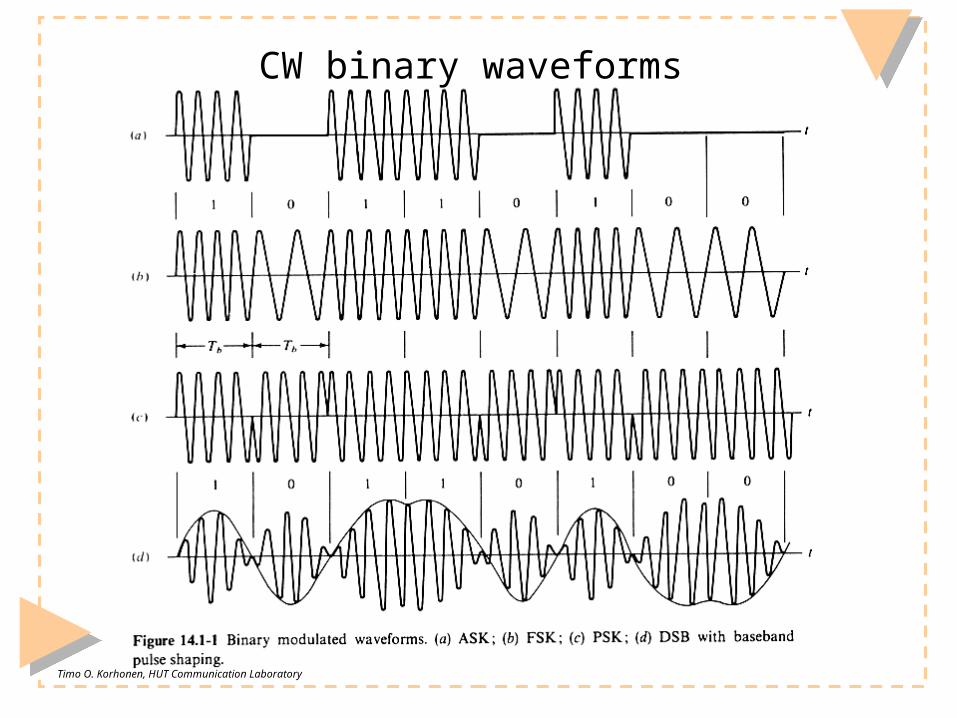
Spectral analysis of CW signals
Apply the quadrature-carrier (complex envelope) form that separates the slow and fast varying parts of the carrier:
The spectra can be decomposed by using modulation theorem
to the following four components:
( ) cos( ( ) )
( ) cos( )cos ( ) si
( )sin(
n( )sin ( )
)( )co ( )( ) s
C C C
C C C C C
C qi CC
x t A t t
x t A t
x t t
t A t t
x tx t t
2
( ) () ( ( )(4
) )i
C
q CCC qi C CG f f G f f G f f G f f
AX t
1( )cos( ) ( )exp ( )exp2C C Cv t t V f f j V f f j

Timo O. Korhonen, HUT Communication Laboratory
M-ary signal equivalent low-pass spectrum: general expression
The respective equivalent lowpass spectra is
M-ary (M-level) baseband signal with the rate r=1/D is represented by
For which the spectra is can be shown to be
where relate to inter-symbol correlation properties for the transmitted symbols ak by
For rectangular NRZ-pulses with Fourier transform yields the PSD:
( ) ( ) ( )lp i q
G f G f G f
( ) ( )i k
kx t a p t kD
2 22 2( ) ( ) ( ) ( ) ( )i a a
nG f r P f m r P nr f nr
2 anda a
m2 2
2
, 0( ) E[ ]
, 0a a
a k k n
a
m nR n a a
m n
Pulse PSD
22 2 2 2
2
1( ) ( ) sinc sinc
D D
fP f p t D fD
r r =F
( ) / 2 / 2D
p t u t D u t D

Timo O. Korhonen, HUT Communication Laboratory
M-ary amplitude shift keying (ASK)
Take the I-component to be an unipolar NRZ signal, hence
For this signal the mean and variance are
( ) ( ), 0,1,..., 1i k D k
kx t a p t kD a M
( 1) / 2a
m M 2 2( 1) /12a
M
22
2 11( ) ( ) sinc ( / ) ( )
12 4lp i
MMG f G f f r f
r
2/ log
T bB r M
2M
Spectral efficiency:
2/ log
b Tr B M
Note the carrier component that does not convey information
2 22 2( ) ( ) ( ) ( ) ( )i a a
nG f r P f m r P nr f nr
2 2
2
1( ) sinc
D
fP f
r rhence
Transmission BW:
Spectral width inversely proportional to the number of bits
For high spectral efficiencystrive to get a rapiddecay

Timo O. Korhonen, HUT Communication Laboratory
Binary Quadrature Amplitude Modulation (QAM)
Note that the orthogonal branch rates are half of the data rate Hence for
Therefore QAM is twice as spectral efficient as ASK Also, impulse that wastes power is missing
20, 1a a
m 2 22 2
,
2 22 2
2 2
0
( ) ( ) ( ) ( ) ( )
1 1( ) sinc ( ) sinc
( / 2) / 2
i q a b a b b bn
D
b b
G f r P f m r P nr f nr
f fP f P f
r r r r
22 24 2( ) ( ) sinc
lp a b
b b
fG f r P f
r r

Timo O. Korhonen, HUT Communication Laboratory
Binary phase reversal keying (PRK)
For two phases PRK is called as binary phase shift keying (BPSK) Modulated carrier can be expressed by
This is in quadrature carrier form
The phases are
Note that phase shift keying has always constant envelope, still for N=1, M=4, phase constellation of PRK and QAM are similar
PRK has however better overall error rate performance due to missing carrier component
( ) ( )cos( )C C D C k
kx t A p t kD t
( ) ( )cos
( ) ( )sin
i D kk
q D kk
x t p t kD
x t p t kD
2, 0,1,... 1, 0 or 1k
k k
a Na M N
M
BPSK =0, =2
0,k
N M
( ( ))
( ) cos( ( ) )
( ) cos ( )cos( ) sin ( )sin( )C C C
C C C C C
i qx tt x
x t A t t
x t A t t A t t

Timo O. Korhonen, HUT Communication Laboratory
PRK constellations
Below PRK with M=4 and M=8 and QAM constellations
2, 0,1,... 1k
k k
a Na M
M M QAM constellation
N=1, no constant envelope

Timo O. Korhonen, HUT Communication Laboratory
Example
Draw the signal constellation and spectrum for a 2-PSK signal with
2 , 4, 0,1k
k k
aM a
M M
cos 1/ 2 / 4
sin 1/ 2
k k
k
k k
I
Q
1( ) ( ) / 2 ( ) ( ), ( ) 12i i b i i bk
x t p t kT G f f p t kT
1 2 1 2
0 0
( ) 0, ( ) 1/ 2T T
k q k qQ T x t dt Q T x t dt
221( ) ( ) sinc /2 2
bq q b
b
rG f P f f rr
21 1( ) ( ) sinc /2 2lp bb
G f f f rr
Note the unnecessary DC-component
2 22 2
,( ) ( ) ( ) ( ) ( )
i q a an
G f r P f m r P nr f nr
2 2
2
1( ) sinc
D
fP f
r r
I
Q
Timo O. Korhonen, HUT Communication Laboratory
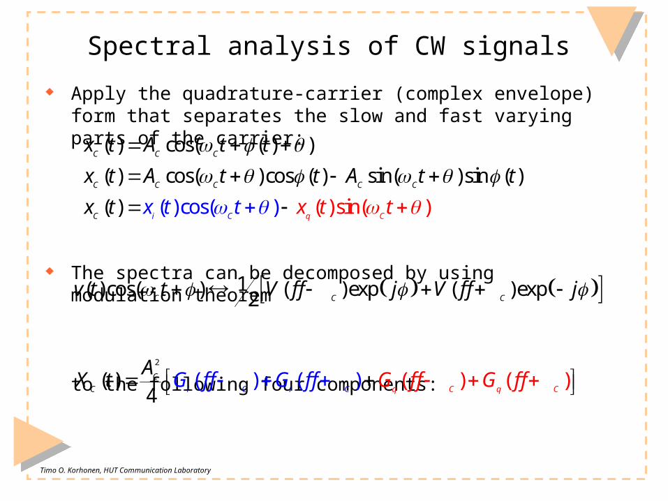
Determining variance < Qi2 > in Maple®

Timo O. Korhonen, HUT Communication Laboratory
Frequency Shift Keying (FSK)
Two frequency modulation methods can be used:
M-ary FSK signal is defined by
Adjacent frequencies are space by 1/Ts=2fd
Phase continuity can be obtained by selecting generator frequencies asmultiples of data rate r=1/D:
Discrete generator M-ary FSK Continuous phase FSK
( ) cos( ) ( )C C C d k D
kx t A t a t p t kD
, 1, 2,... ( 1)k C d k k
f f f a a M
2
/ , 1/(2 )
d
d
S S d
D N
f D N
D T N T f
2d d
f

Timo O. Korhonen, HUT Communication Laboratory
Example of continuous discrete generator M-ary FSK signals
2 4,6,8Hzd
f
bD T
/ , 1/(2 )S S d
D T N T f
1, 2,... ( 1)k C d k
k
f f f a
a M
kf
1f
2f
3f

Timo O. Korhonen, HUT Communication Laboratory
Binary FSK (Sunde’s FSK)
For Sunde’s FSK select Assume rectangular data-pulses:
The lowpass i and q components are obtained from the general FSK expression (constant envelope!):
2, 1/ , 1,b
M D r N 2D b
f r
( ) cos( )
cos( )cos( ) sin( )sin( )i
C C C d kk
C C d k C d kk
qx x
x t A t a t
A t a t t a t
( ) cos( ), / 2i C d k d b
k
dt
x t A a t f r
2
( )
( ) sin( )
sin ( ), 1 0, 1
q C d kk
C k b D b k k kk
kQ p t
x t A a t
A a r t p t kT a Q Q
( ) ( ) ( )D b
p t u t u t kT
/ 2b
rconstant rate: produces at two sided spectra impulses at

Timo O. Korhonen, HUT Communication Laboratory
Sunde’s FSK PSD
PSD was defined by
where now
2 22 2
0
( ) ( ) ( ) ( ) ( )q a b a b b b
nG f r P f m r P nr f nr
( ) ( ) ( )lp i q
G f G f G f
2
2
2
2
22 2
( ) sin ( ), / 2 & modulation theorem
1 / 2 / 2( ) sinc sinc
4
4 cos /
2 / 1
d D b d b
b b
b b b
b
b b
p t t p t kT f r
f r f rP f
r r r
f rr f r
21( ) ( )
4 2 2b b
lp b
r rG f f f r P f
For high spectral efficiencystrive to get a rapid decay

Timo O. Korhonen, HUT Communication Laboratory
Continuous phase FSK
The baseband waveform is defined by
and the modulated carrier is
Substituting x(t) into the integral yields then by using piecewise integration
Thus the CPFSK can be expressed as
0( ) ( ), 1, 2,... ( 1)
k D kk
x t a p t kD a M
0( ) cos x( )
C C C d
t
x t A t d
0
( ) cos ( ) ( )C C C k d k D
kx t A t a t kD p t kD
1
0
k
k d jj
D a
0
0 1
10
, 0
x( ) ( ), 2
( ), ( 1)k
j kj o
ta t t D
d a D a t D D t D
a D a t kD kD t k D
Why does this term enables continuous phase?

Timo O. Korhonen, HUT Communication Laboratory
Minimum-shift keying (MSK)
Analyze CFSK by MSK that is its frequently used form. Now
and its PSD can be shown to be
Note that continuous carrier phase can be illustrated as a phase trellis:
1
02 / 2, 1,
2
k
d b k k jj
f r a a
2
/ 4 / 41( ) sinc sinc
/ 2 / 2b b
lp
b b b
f r f rG f
r r r

Timo O. Korhonen, HUT Communication Laboratory
Coherent binary systems: Error rate analysis
Coherent systems utilize carrier phase information to recover data, thus optimum error rate can be obtained carrier reconstruction required at the receiver carrier reconstruction must be precise
Non-coherent systems decode data without carrier phase reference, thus error rate is deteriorated detection easier when carrier phase recovery related circuits omitted
A good compromise of the coherent and non-coherent techniques are the differentially coherent systems
Concentrate first on AWGN system only Focus on OOK, FSK, PSK Band-limited channels are considered later. Then techniques are introduced to
alleviate or remove produced Inter Symbolic Interference (ISI) Important special case are fading channels that are characterized by statistical
multipath propagation

Timo O. Korhonen, HUT Communication Laboratory
Optimum binary detection
Any bandpass signal can be presented by
This can be expressed by using different waveforms for ‘0’ and ‘1’ bits:
Received waveforms, that indicate the transmitted bits, are recovered coherently by using matched filtering or correlation receiver:
0 0
( ) ( )cos( ) ( )sin( )C C k i b C k q b C
k kx t A I p t kT t Q p t kT t
( ) ( ), 0,1
( ) ( )cos( ) ( )sin( )
C m bk
m C k i C k q C
x t s t kT m
s t A I p t t Q p t t

Timo O. Korhonen, HUT Communication Laboratory
Bases of optimum detection
Received signal consist of bandpass filtered signal and noise, that is then sampled at the time instants tk :
Assuming that the BPF has the impulse response h(t), the signal at the sampling instant is then expressed by
How the bandpass filter impulse response should be selected to maximize received SNR at the time instant of sampling? Let’s first have a look on optimum binary error rate:
( )k m
Y y t z n
( 1)
0
( ) ( )
( ) ( ) ( ( ) x( ) ( ) )
( ) ( )
b
b
b
m m b
m k
m b
k
b
k T
kT A
T
t tz s t kT h t
s h t d x y t y t d
s h d
kT
T
Note how this expression shows
the MF and correlator reception!

Timo O. Korhonen, HUT Communication Laboratory
Optimum binary error rate
Assuming ‘0’ and ‘1’ reception is equally likely, error happens whenthe H0 signal hits the dashed region (or H1 its left-hand side). The decision threshold is at 1 0( ) / 2optV z z
2 20 1 0
1exp / 2 / 2
2opt
e
V
p z d Q z z
Therefore for equally likely ‘0’ or/and ‘1’ the error rate is
For optimum performancewe wish to maximize the
SNR
21 0 / 2z z

Timo O. Korhonen, HUT Communication Laboratory
Impulse response of matched filtering
The signal part of the SNR expression is the difference signal after the bandpass filter (z1 and z0 are convoyed by s1 and s0 respectively):
The noise component of the SNR after the bandpass filter is
And the SNR after the matched filter is:
2
2
1 0 1 0( ) ( ) ( )
bz z s s h dT
22 ( )2
h d
2
21 0
1 2
22
( ) ( ) ( )
4 ( )2
b
b
s s h dz z
h T d
T
( ) ( )cos( ) ( )sin( ) , 0,1
m C k i C k q Cs t A I p t t Q p t t m

Timo O. Korhonen, HUT Communication Laboratory
Using Schwarz’s inequality for optimum filtering
Schwarz’s inequality:
Therefore SNR is maximized at the time instant of sampling by using
2
21 0
21 2
1 022
( ) ( ) ( )( ) ( )
4 ( )2
b
b
s s h dz zK s s d
h T d
T
2
22
2
( ) ( )( )
( )2
V W dV d
W d
1 0( ) ( ) ( )
opt b bh t K s T t s T t
provided that ( ) ( )W KV
1 0that holds when ( ) ( ) ( ) ( ) ( )
bW KV h T K s s

Timo O. Korhonen, HUT Communication Laboratory
Matched filtering and correlator reception
Note that both circuits fulfil the expression0
( ) ( )b
m m opt b
T
z s h dT
Correlator
Matched filter
1 0( ) ( ) ( )
opt b bh t K s T t s T t