Embed Size (px)
Citation preview
USB-Output (Computer):This connects RX2SIM to the computer and also supplies power to RX2SIM. Connect RX2SIM either by plugging it into a USB socket of the PC directly or by using a stan-
PPM-Output:This connector outputs the control signals to your simulator interface. The functionality matches the trainer port of your RC transmitter.
USB-Input (Dongle):Here you can connect the USB interface or dongle of your simulator software. In operating mode “Simulator-Dongle”, RX2SIM connects this port with the computer’s USB port. In operating mode “Game Controller”, this port is not active. If needed, connect your simulator dongle to another USB port of your computer.
RX 2SIM
Fine
st R
C Eq
uipm
ent
AUX
PPM
SRXL
SBUS
MODE
DSM2DSMX
SINGLE CHANNELSUSBPPM
OUT
– + 1 2 3 4 5 6 7 8RX 2SIM
Fine
st R
C Eq
uipm
ent
AUX
PPM
SRXL
SBUS
MODE
DSM2DSMX
SINGLE CHANNELSUSBPPM
OUT
– + 1 2 3 4 5 6 7 8RX 2SIM
Fine
st R
C Eq
uipm
ent
AUX
PPM
SRXL
SBUS
MODE
DSM2DSMX
SINGLE CHANNELSUSBPPM
OUT
– + 1 2 3 4 5 6 7 8
Finest RC Equipment
USB -Output
(Computer)
USB -Input
(Dongle)
Spektrum®DSM2/DSMXremote satellite
JR® DMSSsatellite (RJ01)
• PPM
• SRXL
• S.Bus / S.Bus2
• USB2SYS
Servosingle channels
PPM -Output
(Dongle)
Push button
Manual 1.2 EN
1.2 OVERVIEW
– + K1 K2. . . . . . . . . . . . K8
RX2S
IM
Finest RC Equipment
AUX
PPM
SRXL
SBUS
MOD
E
DSM
2DS
MX
Inpu
t cha
nnel
USBPPM OUT
–+
12
34
56
78
RX2S
IM
Finest RC Equipment
AUX
PPM
SRXL
SBUS
MOD
E
DSM
2DS
MX
SINGL
E CHA
NNEL
S
USBPPM OUT
–+
12
34
56
78
RX 2SIM
Fine
st R
C Eq
uipm
ent
AUX
PPM
SRXL
SBUS
MODE
DSM2DSMX
Input channelUSBPPM
OUT
– + 1 2 3 4 5 6 7 8
RX2SIM
Fine
st R
C Eq
uipm
ent
AUX
PPM
SRXL
SBUS
MODE
DSM2DSMX
SINGLE CHANNELSUSBPPM
OUT
– + 1 2 3 4 5 6 7 8
1.1 SPECIFICATION
• Operating Voltage: 3.8V – 6.0V (typical 5.0V)
• Dimensions (LxWxH): 92 x 42 x 20 mm• Weight: 32g
signalground
3,5mm phone jack, 2-pole (mono)
RX2SIMRX2SIM
This instruction manual only applies to the latest RX2SIM �rmware version! Perform a �rmware update with the StudioX software prior the �rst usage.
dard type A USB extension cable. If the connection is made through a USB hub, the hub should provide a separate power supply in order to avoid current overload of the PC’s USB port in case more than one USB device is active at the same time.
Receiver:RX2SIM supports various types of RC receivers. Either you connect a receiver with up to eight separate servo channels or the functions are transmitted by one single line using a special Single-Line protocol. Here RX2SIM supports Futaba® S.Bus/S.Bus2, SRXL, PPM-serial signal (SPPM) or you can also connect one single Spektrum® DSM2/DSMX remote satellite or a JR® RJ01 DMSS satellite.
In general the receiver does not need a separate power supply as RX2SIM supplies 5V power to the receiver. Other devices (like servos) must not be connected to the receiver in order to avoid excessive current consumption! To prevent damage to RX2SIM or to the USB port the output current is limited to 100mA at port [- + 1]. If your receiver requires higher current or voltage you must power it separately. In this case the (+) pole (red wire) between receiver and RX2SIM must be cut or unplugged to prevent from damaging the USB port due to overvoltage.
2.1 CONNECTING A RECEIVER WITH SEPARATE SERVO OUTPUT CHANNELS
three-wire patch cable. This connection also supplies voltage for the receiver. Connect channels 2 to 8 using the 7-wire patch cable. On these servo plugs only the signal line (orange wire) is connected.
Please refer to your receiver’s manual or the imprint on its case to determine which pin is the impulse line on each servo connector.
• Satellite port: 3.3V, max. 100mA (unlimited)

2.2 RECEIVER WITH S.BUS, S.BUS2, SRXL OR SERIAL PPM PORT2.1 CONNECTING A RECEIVER WITH SEPARATE SERVO OUTPUT CHANNELS
Computer · Computer ·
S.Bus, S.Bus2 or
SRXL-Receiver or
Receiver with serial PPM signal
Patch cable(3-wire)
Computer · Computer ·
Simulator-Interface*
Simulator-Interface*
Functional description:The control signals are transmitted through the patch cable from the receiver to RX2SIM, which forwards the controls via USB to the computer as game controller axes and buttons.
Functional description:The control signals are transmitted from the satellite to RX2SIM, which forwards the controls via USB to the computer as game controller axes and buttons.
Connect RX2SIM with the receiver by using the 3-wire patch cable.
Connect RX2SIM to the Satellite by using the appropriate Spektrum Satellite cable.
Connect RX2SIM with the receiver by using the 3-wire patch cable.
Connect RX2SIM to the satellite by using the appropriate Spektrum® remote satellite cable.
Functional description:The control signals are transmitted through the patch cable from the receiver to RX2SIM, which combines them into a serial PPM signal that is fed into the simula-tor interface. The simulator interface forwards the PPM signal via USB to the computer.
Functional description:The control signals are transmitted from the satellite to RX2SIM, which combines them into a serial PPM signal that is fed into the simulator interface. The simulator interface forwards the PPM signal via USB to the computer.
MODUS „GAME CONTROLLER“MODUS „GAME CONTROLLER“ MODUS „GAME CONTROLLER“
MODUS „SIMULATOR DONGLE“MODUS „SIMULATOR DONGLE“ MODUS „SIMULATOR DONGLE“
Patch cable (3-wire)
Satellite cable (3-wire)
Computer ·
RC Receiver
Simulator-Interface*
Functional description:The control signals are transmitted separately (one line for each servo channel) from the receiver to RX2SIM, which combines them to a serial PPM signal that is fed into the simulator interface. The simulator interface forwards the PPM signal via USB to the computer.
Patch cable (7-wire)
Patch cable (3-wire)
Computer ·
RC Receiver
Patch cable (7-wire)
Patch cable(3-wire)
Functional description:The control signals are transmitted separately (one line for each servo channel) from the receiver to RX2SIM, which forwards the controls via USB to the computer as game controller axes and buttons.
S.Bus, S.Bus2 or
SRXL-Receiver or
Receiver with serial PPM signal
RX2S
IM
Finest RC Equipment
AUX
PPM
SRXL
SBUS
MOD
E
DSM
2DS
MX
Inpu
t cha
nnel
USBPPM OUT
–+
12
34
56
78
RX2S
IM
Finest RC Equipment
AUX
PPM
SRXL
SBUS
MOD
E
DSM
2DS
MX
SINGL
E CHA
NNEL
S
USBPPM OUT
–+
12
34
56
78
RX2S
IMFinest RC Equipment
AUX
PPM
SRXL
SBUS
MOD
E
DSM
2DS
MX
Inpu
t cha
nnel
USBPPM OUT
–+
12
34
56
78
RX2S
IMFinest RC Equipment
AUX
PPM
SRXL
SBUS
MOD
E
DSM
2DS
MX
SINGL
E CHA
NNEL
S
USBPPM OUT
–+
12
34
56
78
RX2S
IM
Finest RC Equipment
AUX
PPM
SRXL
SBUS
MOD
E
DSM
2DS
MX
Inpu
t cha
nnel
USBPPM OUT
–+
12
34
56
78
RX2S
IM
Finest RC Equipment
AUX
PPM
SRXL
SBUS
MOD
E
DSM
2DS
MX
SINGL
E CHA
NNEL
S
USBPPM OUT
–+
12
34
56
78
RX2S
IM
Finest RC Equipment
AUX
PPM
SRXL
SBUS
MOD
E
DSM
2DS
MX
Inpu
t cha
nnel
USBPPM OUT
–+
12
34
56
78
RX2S
IM
Finest RC Equipment
AUX
PPM
SRXL
SBUS
MOD
E
DSM
2DS
MX
SINGL
E CHA
NNEL
S
USBPPM OUT
–+
12
34
56
78
RX2S
IM
Finest RC Equipment
AUX
PPM
SRXL
SBUS
MOD
E
DSM
2DS
MX
Inpu
t cha
nnel
USBPPM OUT
–+
12
34
56
78
RX2S
IM
Finest RC Equipment
AUX
PPM
SRXL
SBUS
MOD
E
DSM
2DS
MX
SINGL
E CHA
NNEL
S
USBPPM OUT
–+
12
34
56
78
RX2S
IM
Finest RC Equipment
AUX
PPM
SRXL
SBUS
MOD
E
DSM
2DS
MX
Inpu
t cha
nnel
USBPPM OUT
–+
12
34
56
78
RX2S
IM
Finest RC Equipment
AUX
PPM
SRXL
SBUS
MOD
E
DSM
2DS
MX
SINGL
E CHA
NNEL
S
USBPPM OUT
–+
12
34
56
78
Spektrum® satellite
orJR® RJ01satellite
Satellite cable (3-wire)
* Simulator-Interface (Dongle) not included. This is part of your RC �ight simulator.
Spektrum® satellite
orJR® RJ01satellite
2.3 SPEKTRUM® OR JR® REMOTE SATELLITE
RX 2SIM
Fine
st R
C Eq
uip
men
tAUX
PPM
SRXL
SBUS
MODE
DSM2DSMX
Input channelUSBPPM
OUT
– + 1 2 3 4 5 6 7 8
RX 2SIM
Fine
st R
C Eq
uip
men
tAUX
PPM
SRXL
SBUS
MODE
DSM2DSMX
SINGLE CHANNELSUSBPPM
OUT
– + 1 2 3 4 5 6 7 8
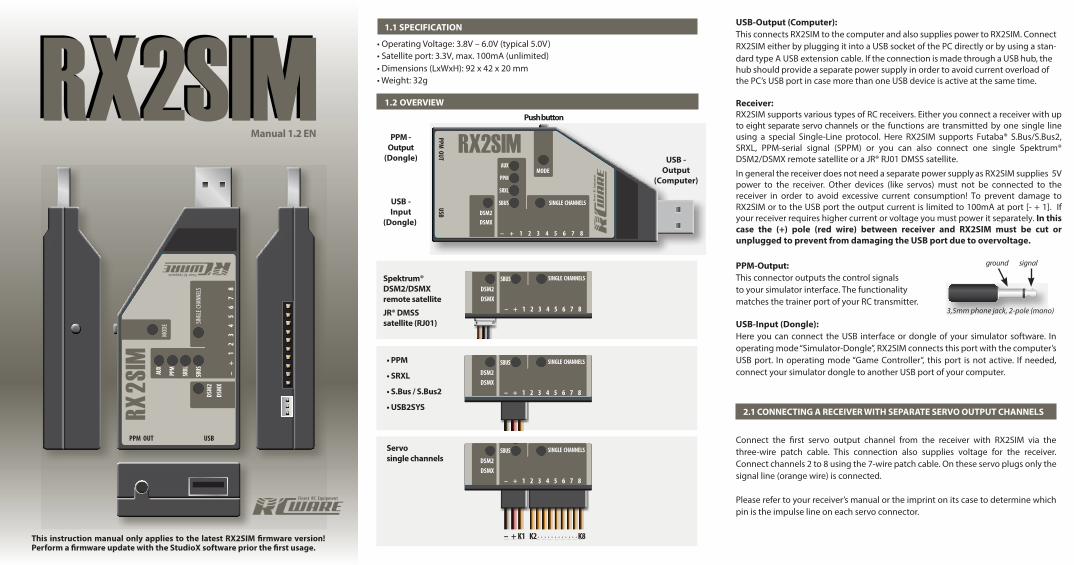
3 SETUP PROCEDURE
Connect RX2SIM to your RC receiver and simulator interface according to the appli-cable picture. Then plug RX2SIM to an available USB port of your computer.
3.1 OPERATION MODE
3.2 RECEIVER TYPE SELECTION
In order to decode the control signals from the connected receiver RX2SIM has to be set to the appropriate receiver type.
1. PPM (serial signal)2. SRXL3. Futaba S.Bus/S.Bus2
Green = Simulator-Dongle (USB looped through)
Purple = Game Controller (RX2SIM acts as USB-Joystick)
Orange = USB2SYS(for connection PC->SYS port)
IMPORTANT:
4 ADDITIONAL OPTIONS
4.1 RECEIVER BINDING
In order to reset RX2SIM to factory defaults press and hold the button while4.2 RESET TO FACTORY DEFAULTS
connecting it to the computer. Then release the button. Two blue LEDs will light up.
4.3 FIRMWARE UPDATE/INSTALLATION OF ADDITIONAL FUNCTIONS
4.4 ENABLE OR DISABLE OPERATING MODES
DECLARATION OF CONFORMITY
Select receiver type (section 2.2): Press button for a long period
Select operation mode(section 2.1):Brie�y press button
Single servo channels
Push button
Please do not press the button on RX2SIM at this time. Otherwise you may enter �rmware update mode.
Green: Simulator-Dongle
The receiver output signals are available at the PPM output jack. Any simulator interface or USB-Dongle that is connected to RX2SIM will be connected through RX2SIM with the computer’s USB port. So this operation mode can be used for �ying your RC �ight simulator wireless and without the need for connecting the simulator to your transmitter‘s trainer port.
Purple: Game Controller
In this mode RX2SIM operates as a USB game controller. The various RC servo channels are mapped to the di�erent axes and buttons of the game controller. So you can use your RC transmitter as wireless joystick for computer games or di�erent �ight simulators. Also the controls are available at the PPM output jack but in comparance to the „Simulator-Dongle“ mode the USB-input port will not be powered and is not connected to the USB-output.
Orange: USB2SYS
In this mode RX2SIM acts as BEASTX USB2SYS interface and can be used as communication interface for MICROBEAST/MICROBEAST PLUS. Connect the 3-wire patch cable to the very left port at RX2SYS marked [- + 1]. The other end of the cable connects to the SYS port of MICROBEAST/MICROBEAST PLUS. Watch out for correct polarity! Note: You mustn‘t connect any servos to MICROBEAST when RX2SIM is used to power the device. Otherwise when MICROBEAST is powered by a separate power supply (i. e. for power the servos) this must not provide more than 6V output voltage! Otherwise RX2SIM or the computer‘s USB port will get damaged. So when you power MICROBEAST with a higher voltage level disconnect or cut the (+) pole (red wire) between RX2SIM and SYS port.
4. Spektrum®DSM2/DSMX or JR® RJ01 DMSSsatellite
become active and the mode LED stops �ashing. The selected mode will stay selected even when the device is powered o�. By default you can choose between the following operation modes: The selected receiver type will stay selected even when the device is powered o�.
To bind the receiver to the transmitter please follow the instruction manual of your radio control system. There is one specialty when using a single Spektrum® remote satellite connected to RX2SIM. In this case the bind sequence on the receiver must be initiated by RX2SYS. For this connect RX2SIM to the computer and set „Spektrum®“ as receiver type on the RX2SIM (see section 3.2) before connecting the Spektrum® satellite to RX2SIM. When using a DSM2 remote satellite additionaly connect the 3-wire patch cable to the very left port marked [- + 1] on RX2SIM. The other end of the patch cable plugs into one of the other ports on the right. To bind a DSMX remote satellite you don‘t connect the patch cable. Now please plug in the satellite connector quickly, so that all contacts connect nearly at the same time. This will place the satellite in bind mode (satellite LED �ashing quickly) and you can initiate bind sequence on the transmitter. If this does not work immediately, repeat plugging the satellite out and in again for another trial.
By brie�y pressing the button you can change the operation mode. RX2SIM will
mode. After a few seconds without further button press the preselected mode will
(applicable for operating modes Simulator-Dongle and Game Controller)
Press and hold RX2SIM’s button for a long period (> 5 seconds) until Then release the button.
- The LED will light up continuously if RX2SIM detects proper signals from the receiver.
- T-
ration of the receiver itself.
nuous light. Release the button now to restore RX2SIM’s factory defaults. -
The �rmware of RX2SIM can be upgraded or updated to newer releases by using the StudioX software. To start RX2SIM in �rmware update mode press and hold the button before and while connecting RX2SIM to the computer. Then immediately release the button so that the two blue LEDs will light up constantly. Now start StudioX on the computer and follow the update instructions of the software. When the update was �nished successfully RX2SIM will restart automatically with the new or updated �rmware.
Unused operating modes can be disabled so you don’t have to skip them anytime when switching between operating modes. Likewise, disabled modes can be enabled again. Press and hold the button while connecting RX2SIM to the computer. Holdthe button until the Mode LED shows the color of the mode you wish to enable or disable. To enable the mode release the button while the blue LEDs are on. To disa-
This device conforms to the basic requirements and other relevant regulations of corresponding CE directives.
The original Declaration of Conformity can be found on the Internet at www.rcware.de at the respective product description.