Embed Size (px)
Citation preview

TWO DIMENSIONAL MESOSCALE SIMULATIONS OF PROJECTILE
INSTABILITY DURING PENETRATION OF DRY SAND
By
RUSSELL DANIEL TEETER M.S.
A thesis submitted in partial fulfillment of
the requirements for the degree of
MASTER OF SCIENCE IN MECHANICAL ENGINEERING
WASHINGTON STATE UNIVERSITY School of Mechanical and Materials Engineering
December 2007

ii
To the Faculty of Washington State University:
The members of the Committee appointed to examine the thesis of RUSSELL DANIEL TEETER and find it satisfactory and recommend that it be accepted.
___________________________________ Chair
___________________________________
___________________________________

iii
ACKNOWLEDGMENTS
I first thank my advisor, Dr. Yogendra M. Gupta whose experience and support
have been instrumental in the completion of this thesis. Dr. Gupta has always placed my
personal development as a graduate student above all else, for this I am truly grateful. I
would also like to thank Dr. Conrad W. Felice whose valuable input has guided this
work. I also express appreciation to my Graduate Committee members, Dr. Jow-Lian
Ding and Dr. David P. Field, for their guidance and time spent evaluating this thesis.
The time that Dr. Sunil Dwivedi has invested in me has been significant. It is he
who introduced me to the mesoscale problem as an undergraduate and whose
computational expertise has been invaluable for my graduate work. Over the years I have
developed a deep respect for Dr. Dwivedi, and thank him for always having acted in my
best interest.
I would also like to thank my parents, Verna and Gerald Teeter, for 25 years of
love and guidance (as well as four and a half years of undergraduate tuition payments). I
am greatly indebted to my wife, Trista Teeter, for her unwavering support during my
graduate work. Last of all, I thank my daughter, Brooklyn, whose very existence has
brought me happiness on even my most trying days.
This work was supported by AFOSR and DOE.

iv
TWO DIMENSIONAL MESOSCALE SIMULATIONS OF PROJECTILE
INSTABILITY DURING PENETRATION OF DRY SAND
ABSTRACT
By Russell Daniel Teeter M.S. Washington State University
December 2007
Chair: Yogendra M. Gupta
Projectiles penetrating geologic media can experience instabilities characterized
by divergence from their initial path and projectile bending. To gain insight into the
effects of geologic features on projectile instability, a set of 2D non-continuum
(mesoscale) simulations which account for the granular nature of sand was completed.
The physical features of dry sand were accounted for by explicitly modeling and tracking
each grain of sand in the target created using the program ISP-SAND. Penetration
simulations were performed using the Lagrangian multi-body finite element code ISP-
TROTP. Projectile instability was examined using projectile rotational momentum,
unbalanced off-axis forces, and projectile deviation from path. Specific variables of
interest were penetration velocity, grain size, grain distribution, target porosity, inter-
granular friction, material properties, and sand grain randomness. Results show that the
granular system can produce unbalanced radial forces which cause a projectile to become
unstable. In all cases where penetration velocity was considered, projectiles became
increasingly unstable as penetration velocities increased from 0.5 km/s to 1.5 km/s. For
the cases considered, the effect of different target properties on projectile instability have

v
been quantified with reference to a set of baseline simulations. Throughout the
simulations, which consider an elastic penetrator, an oscillation is seen with a uniform
length scale that correlates with the lowest projectile bending mode.

vi
TABLE OF CONTENTS
ACKNOWLEDGMENTS ................................................................................................. iii
ABSTRACT....................................................................................................................... iv
LIST OF FIGURES ........................................................................................................... ix
LIST OF TABLES........................................................................................................... xiv
SECTION 1 Introduction.................................................................................................... 1
1.1 Motivation................................................................................................................. 1
1.2 Objective and Approach ........................................................................................... 3
1.3 Organization of the Thesis........................................................................................ 4
SECTION 2 Background .................................................................................................... 5
2.1 Experimental Evidence of Projectile Instability....................................................... 5
2.2 Instability Explanations ............................................................................................ 7
2.3 Mesoscale Description.............................................................................................. 9
SECTION 3 Methodology ................................................................................................ 12
3.1 Target Size and Boundary Conditions .................................................................... 16
3.2 Penetrator Geometry ............................................................................................... 17
3.3 Material Models...................................................................................................... 19
3.4 Measures of Instability............................................................................................ 25
3.5 Parameters Studied ................................................................................................. 26
SECTION 4 Mesoscale Target Creation........................................................................... 29
4.1 Overview of Mesoscale Target Development ........................................................ 29
4.2 ISP-SAND .............................................................................................................. 31
4.2.1 Initial Grain Site Placement ............................................................................. 31

vii
4.2.2 Modified Voronoi Tessellation........................................................................ 42
4.2.3 Mesh Generation.............................................................................................. 49
4.2.4 Process Validation ........................................................................................... 52
4.2.5 Regular and Irregular Grain Placement ...........................................................56
4.2.6 ISP-SAND Conclusion .................................................................................... 57
4.3 Projectile Properties................................................................................................ 57
SECTION 5 Results and Discussion................................................................................. 60
5.1 1-3 Baseline Simulations (inelastic grains, plastic impactor at three velocities)... 60
5.1.1 Inelastic Deformation of the Projectile ............................................................ 64
5.1.2 Stress Fingers ................................................................................................... 65
5.1.3 Instability Measures......................................................................................... 66
Another measure of instability, the projectile rotational momentum, is shown in Figure
5.4. Examining the projectile rotational momentum shows that, increasing projectile
velocity results in increasing rotational momentum. The rotational momentum shown
is again obscured by the large inelastic deformation of the projectile. However, the
trend of increasing instability with increasing velocity remains when considering
elastic projectiles........................................................................................................... 66
5.2 4-6 Baseline Simulations (inelastic grains, elastic impactor at three velocities)... 67
5.3 Effect of Sand Grain Strength:................................................................................ 75
5.4 Effect of Grain Size and Grain Size Distribution: .................................................. 78
5.5 Effect of Random Placement of Sand Grains: ........................................................81
5.6 Effect of Porosity: ................................................................................................... 85
5.7 Effects of Friction: .................................................................................................. 87

viii
5.8 Deep Penetration Results ........................................................................................ 89
5.9 Examination of the Oscillations.............................................................................. 89
5.9.1 Projectile Resonance........................................................................................ 92
SECTION 6 Summary and Conclusions .......................................................................... 99
BIBLIOGRAPHY........................................................................................................... 101
Appendix A : Finite Element Mesh Size Selection ........................................................ 106
Appendix B : Vibration Mode Code Validation ............................................................. 111
Appendix C : Matlab Bending Mode Program............................................................... 113

ix
LIST OF FIGURES
Figure 2.1: Penetrator positioned above a sand target. Individual sand grains and porous
regions are represented explicitly in the mesoscale approach. .........................................10
Figure 3.1: A typical 2D projectile and sand target created by ISP-SAND. The target has
a porosity of 30% and each grain is modeled as simple (no phase change and non-
damaging) quartz. The projectile is hardened steel having a tip modified 3.5 CRH
Projectile with an l/d ratio of 3.85 and is modeled as hardened steel. .............................. 13
Figure 3.2: Geometric construction of a tangent ogive projectile ................................... 18
Figure 3.3: Linear fit of power law yield strength........................................................... 21
Figure 3.4: Mean stress dependent equilibrium yield strength ......................................... 23
Figure 4.1: 2-D Gaussian function centered at GS1 and showing overlapping GS2........ 34
Figure 4.2: Grain sites shown after initial overlap checking. Vectors represent the
direction of displacement.................................................................................................. 37
Figure 4.3: Grain sites shown after 20 displacement iterations. ......................................37
Figure 4.4: Grain sites shown after 40 displacement iterations. .......................................38
Figure 4.5: Grain sites shown after 100 displacement iterations. Patterns can now clearly
be seen in the grain sites. .................................................................................................. 38
Figure 4.6: Overlap energy as a function of iterations. Each line shows different
maximum step sizes which correspond to the mean grain size multiplied by a scaling
factor. As step size increases, the convergence rate increases until a point at which
convergence no longer occurs........................................................................................... 39
Figure 4.7: Large domain segmented into smaller sub domains. The orange box contains
points that are being checked and the green boxes contain points that can interact with the
points in the orange box.................................................................................................... 41

x
Figure 4.8: Schematic of steps used to produce a Voronoi tessellation. A: Points that
will be tessellated, B: Neighbor search to define contributing points, C: Bisection of lines
connecting contributing points. D: Location of bisector intersections, E: Final tessellation
........................................................................................................................................... 43
Figure 4.9: VT of sites generated with ISP-SAND. Dots represent the sites and the lines
represent the VT. In this domain, the small sub zones will be removed to yield a porous
sample. Notice that the tessellation has an averaging effect on the grain size. Grains and
voids that border one another have been distorted in a way that decreases the grain size
and increases the void size................................................................................................ 44
Figure 4.10: Optimization of Voronoi tessellation. The VP is shifted to minimize the
difference between the assigned radius of the GS and the distance between the GS and
the VP................................................................................................................................ 47
Figure 4.11: Modified VT of sites generated with ISP-SAND. Grain and void sites are
clearly visible. Grain sites are expanded to their assigned diameters and void sites have
been condensed to their assigned diameters. .................................................................... 48
Figure 4.12: Mesh produced by connecting VPs to grain centers of area. ....................... 51
Figure 4.13: Tridelaunay mesh created using Cubit 9.1. .................................................. 51
Figure 4.14: Grain size distribution for input of 60µm grain size. The mean grain size is
59.87 and shows close correspondence to input parameters............................................. 53
Figure 4.15: 60µm uniform grains ................................................................................... 53
Figure 4.16: Grain size distribution for input of 45 -75um grain size. The mean grain size
is 60.07um and shows close correspondence to input parameters.................................... 55
Figure 4.17: Grains ranging in size from 45 – 75 um....................................................... 55
Figure 4.18: Grain size distribution for input of 45-75µm grain size. These grains were
placed initially in a more normal way than those seen in previous tests. ......................... 58

xi
Figure 4.19: Grains ranging in size from 45-75 µm with more homogeneous porosity and
grains................................................................................................................................. 58
Figure 4.20: Tangent ogive projectile with 10um triangular mesh................................... 59
Figure 5.1: Plastic penetrator entering inelastic grains at, left 500 m/s, center 1000 m/s,
right 1500 m/s. Showing contours of Y velocity, X velocity, and effective stress.......... 61
Figure 5.2: Plastic penetrator entering inelastic grains at, left 500 m/s, center 1000 m/s,
right 1500 m/s. Showing contours of X Stress, Y Stress, and shear stress...................... 63
Figure 5.3 Lateral forces on the plastic penetrator from simulations 1 and 3 show large
lateral forces at increased penetration velocity. ................................................................ 68
Figure 5.4 Rotational Momentum curves corresponding to the projectiles in simulations
1-3 ..................................................................................................................................... 69
Figure 5.5 Elastic penetrator entering inelastic grains at, left 500 m/s, center 1000 m/s,
right 1500 m/s. Showing contours of Y velocity, X velocity, and effective stress.......... 70
Figure 5.6: Elastic penetrator entering inelastic grains at, left 500 m/s, center 1000 m/s,
right 1500 m/s. Showing contours of X Stress, Y Stress, and shear stress...................... 71
Figure 5.7 Rotational momentum curves corresponding to the projectiles in simulations
4-6 showing greater instability at higher velocities .......................................................... 73
Figure 5.8: Lateral forces applied to elastic projectile in runs 4-6. Forces increase
significantly with velocity................................................................................................. 74
Figure 5.9: Plastic (left) and elastic (right) penetrators entering elastic grains at 1500 m/s.
Showing contours of Y velocity, X velocity, and effective stress. ................................... 76
Figure 5.10: Rotational momentum for plastic and elastic penetrators entering elastic
grains at 1500 m/s. ............................................................................................................ 77

xii
Figure 5.11: showing contours of effective stress Left: Elastic Penetrator into inelastic
60µm uniform grains (Run 10), Right: Elastic Penetrator into 84-156 µm grains (Run 12)
........................................................................................................................................... 79
Figure 5.12: Rotational momentum curves for A: Elastic penetrator entering inelastic
60µm uniform grains (Run 10), B: Elastic penetrator entering inelastic 84-156 µm grains
(Run 12) ............................................................................................................................ 80
Figure 5.13: Elastic penetrators fired into 42-78µm targets with random seed variation,
showing contours of effective stress. Runs 13, 15, and 16. .............................................. 82
Figure 5.14: Rotational Momentum of 5 projectiles fired into targets with similar grain
sizes and porosities. .......................................................................................................... 83
Figure 5.15: Rotational momentum of penetrators fired into clustered grains. Showing 1:
Plastic Penetrator (Run 17) and, 2: Elastic Penetrator (Run 18).......................................84
Figure 5.16: plots showing effective stress at one depth of penetration in 40% porous
target Left: Plastic Projectile (Run 19), Right: Elastic Projectile (Run 20)...................... 85
Figure 5.17: Rotational Momentum curves for plastic and elastic projectiles penetrating
40% porous targets............................................................................................................ 86
Figure 5.18: Plots showing effective stress at one depth of penetration in frictionless
targets Left: plastic projectile (simulation 21), Right: elastic projectile (simulation 22) . 87
Figure 5.19: Rotational momentum plots of plastic and elastic projectiles penetrating
frictionless targets ............................................................................................................. 88
Figure 5.20: Deep penetration runs showing contours of effective stress, considering an
elastic penetrator and elastic grains. A: frictionless penetration displays little instability
B: frictional penetration shows instable behavior............................................................. 90
Figure 5.21: Rotational momentum curves of elastic penetrators impacting frictional and
frictionless targets up to 3.5 penetration lengths.............................................................. 91

xiii
Figure 5.22: First three bending shapes arranged from lowest (left) to highest (right)
showing contours of effective stress 3
2 ij ijS S ................................................................. 94
Figure 5.23: Calculated rotational momentum for projectiles with different densities ... 96
Figure 5.24: Calculated radial momentum for projectiles with different densities .......... 97
Figure A.1: Snapshot at .65 us showing the deformation field in the 10µm mesh size
penetrator and grains....................................................................................................... 108
Figure A.2: Snapshot at .65 us showing the deformation field in the 5µm mesh size
penetrator and grains....................................................................................................... 109
Figure A.3: Rotational momentum curves emphasizing projectile mesh size effects. .. 110
Figure B.1 First three calculated bending modes showing contours of effective stress
(arbitrary units) ............................................................................................................... 112

xiv
LIST OF TABLES
Table 3.1: Artificial viscosity values ............................................................................... 15
Table 3.2: Material properties for the steel projectile...................................................... 24
Table 3.3: Material properties used for the quartz sand grains........................................ 24
Table 3.4: List of Simulations........................................................................................... 28
Table 5.1: List of simulations displaying average lateral forces and final x displacements.
........................................................................................................................................... 62
Table 5.2: Projectile resonant modes ................................................................................ 93
Table 5.3: approximate oscillation periods for various density penetrators .................... 97
Table B.1: Bending modes for a cantilever beam.......................................................... 111

1
SECTION 1 Introduction Introduction
This work constituted the initial phase of an ongoing effort to develop insight into
possible causes of projectile instability when penetrating dry granular media (sand). To
accomplish this, 2D finite element mesoscale simulations of projectile penetration into
dry sand were conducted, and the sand grains were modeled explicitly to account for their
response and interactions. A number of simulations were performed to quantify the
effects of target parameters on projectile response. The work related to these simulations
is presented here.
1.1 Motivation
Penetration of geologic media has been long studied with a focus on predicting
depth of penetration (DOP). Starting in the eighteenth century[1], Robins[2] and Euler
modeled penetration assuming that projectiles continued along their initial paths and
experienced a constant deceleration. Since then a number of different DOP predication
methods have been developed. These methods include the Poncelet[3, 4] method and
cavity expansion[5] methods to name two approaches. In many cases, these types of
methods work well and accurately predict penetration depth. However, there are a
growing number of cases where these simple models fail and significantly overestimate
penetration depth.
As a new generation of earth penetrators are developed, an emphasis has been
placed on increased penetration depth and decreased damage to surrounding structures.
Although these two requirements seem to be in opposition, one possible solution would
be to use relatively small size high velocity projectiles[6]. To implement such a strategy,

2
a number of issues need to be understood. One of these issues, and the topic of this work,
is a trend found in which projectiles become unstable when they decrease in size or
increase in velocity[1, 7-11].
Projectile instability is characterized by severely bent or failed projectiles as well
as projectile tumbling and deviation from the expected path[8, 10, 11]. This type of
instability cannot be explained using the above DOP methods because unstable
projectiles violate the implicit assumption (in these approaches) that projectiles remain on
a nearly straight path during penetration. For this reason, the approach taken in this work
was to simulate the early stages of penetration using a 2D approximation while taking
into account the particulate nature of the targets: mesoscale features. The term mesoscale
means that each randomly placed sand grain was simulated as it moved and interacted in
the target. The inclusion of the sand grains in the model is necessary because it provides
a realistic description of the sand media. The resulting heterogeneous loading on the
projectile may cause the observed instability[12].
In these simulations, there are a number of variables which are not readily known.
For example, determining the coefficient of friction between two sand grains at high
relative velocities and large contact forces is not simple. Another feature that is not
readily known is the material description of a grain of sand. Because there are a number
of parameters, like these that are unknown, the intent of this work was not to accurately
predict penetration depth. Instead, it was develop an understanding of the possible
features which can causes projectile instability.

3
1.2 Objective and Approach
This work is the initial phase of a project to understand projectile instability
during penetration. To begin developing this understanding, this work numerically
examined the effects of grain scale heterogeneities (intergranular friction, grain size,
grain shape, target porosity, etc) on projectile response during high velocity (1500 m/s)
penetration of granular media. Specifically, three objectives were completed:
1. To realistically model the grain scale features of a granular media.
2. To simulate penetration into the granular media using tangent ogive projectiles.
3. To quantify the effects of grain scale features on projectile instability.
The first objective was completed using a Fortran program ISP-SAND, adapted from
an earlier code written to produce polycrystalline metal domains. ISP-SAND uses an
energy minimization technique along with Voronoi tessellation to place and construct the
individual sand grains.
The simulations were carried out using the Lagrangian finite element code ISP-
TROTP developed by Dr. Sunil Dwivedi. ISP-TROTP is an explicit multi-body wave
propagation code with a robust contact algorithm which is a requirement for these
simulations. These simulations required considerable computing power and ISP-TROTP
was run on an Altix 4700 super computer, utilizing between 4 and 16 processors.
The effects of the mesoscale features on the projectile response were quantified in a
number of ways. The simplest method was by visual inspection of the simulation results.
If the projectile appeared to be tilted after one penetration depth then it was likely
experiencing instability. Besides visual inspection, a number of more quantitative
methods were also used to examine projectile instability. These methods quantified the

4
projectile rotational momentum, lateral displacement of the projectile center of mass, and
the average lateral force applied to the projectile.
1.3 Organization of the Thesis
The ensuing sections provide the following information. Section two presents
background information and cites instances when penetrator instability was found during
penetration of geologic media. Methods used to explain projectile instability are
discussed, and an overview of the mesoscale is given.
Section three contains a description of the simulation procedure. Topics such as
target boundary conditions, target parameters, and measures of instability are discussed.
Also, a discussion of the material models which were used is given
Section four has an in depth explanation of ISP-SAND. and discusses the sand
placement method and the creation of the grain geometry. Section four also includes a
verification of the numerical approach to produce specific targets as well as the meshing
procedures used for both the target and penetrator geometry.
Section five details the simulation results, discusses the effects of various
parameters on the penetration event and penetrator instability, and also discusses a
possible cause of projectile instability. Finally, section six provides a summary and
conclusions.

5
SECTION 2 Background Background
A compilation of the relevant literature is presented here. Section 2.1 discusses
various experimental results where penetrator instability has been found. Section 2.2
discusses different explanations of projectile instability found in the literature. Section
2.3 is a description and explanation of the mesoscale simulation procedure developed by
Dwivedi[13] and used in this work.
2.1 Experimental Evidence of Projectile Instability
A number of authors have reported penetrator instability during penetration into
sand and geologic materials. In some cases, producing penetrator instability was the
intent of the experiment. In others, the intent of the experiments was to avoid unstable
penetration, but incremental increases in penetration velocity caused the penetrators to
become unstable.
Allen et al.[1] fired 13mm diameter steel projectiles with length to diameter (l/d)
ratios of 10 into unconfined sand targets. These projectiles had conical nose cones with
varying nose cone angles. It was noted that the projectiles with nose cone angles less
than 90 degrees became unstable (the smaller the angle the sharper the projectile) at
velocities above 600 m/s, deviating from straight path and showing a decrease in
penetration depth. It was also noted that projectiles left a trail of fine powered dust,
illustrating sand grain fracture.
Biele[7] fired 13 mm diameter projectiles with 7.7 l/d ratios and conical tips into
sand targets at 300 m/s and found that projectiles diverged from their expected paths.
Byers et al.[9] displayed instability in a full scale projectile with a diameter of 155 mm

6
and an l/d ratio of 10. The penetrator was fired normally into a hard lake bed using a
Davis gun at 300 m/s. The projectile had an ogive tip and became unstable leading to
catastrophic failure. Frew et al.[14] found bending in steel and Aermet 100 projectiles
with diameters of 7.1mm and 12.7mm. These projectiles had a 3 Caliber Radius Head
(CRH) nose geometry and l/d ratios of 10. They were fired into limestone targets at 1600
and 1700 m/s and had initial pitch and yaw of less than 1 degree. Penetrators were found
to be severely bent and to diverge from the initial path.
Savvateev et al.[11] fired tungsten alloy bullets with diameters of 4.7 mm and
steel bullets with diameters of 6 mm, and length to diameter (l/d) ratios of 4.5 and 13.75
into dry sand at velocities ranging from 1.3 to 4 km/s. The recovered bullets were found
to remain on a nearly straight path (shown using witness plates) but were highly
deformed, possibly melted (depending upon initial kinetic energy), and had tumbled
during penetration. It was also found that penetration depth decreased after a critical
penetration velocity was reached.
Jones et al.[10] observed severe penetrator bending in 4.2mm and 12.7mm
diameter projectiles with l/d ratios of approximately 10. The 12.7 mm diameter projectile
was a steel ogive projectile and was fired into Eglin sand at 1500 m/s. The 4.2 mm
diameter projectile was an aluminum ogive projectile and was fired into alumina power at
700 m/s. Both projectiles revealed similar bending upon final inspection. Along with
bending, projectiles also deviated from their initial path.
As seen from the above reports of penetration experiments, there is a wide range
of cases where projectiles exhibit instability. In each of these cases, projectile instability
limited the penetration velocity at which projectiles could be fired effectively into

7
geologic targets. To mitigate this limitation, the underlying causes of penetrator
instability need to be understood.
2.2 Instability Explanations
Explaining the causes of projectile instability is complicated due to the intense
environment created during penetration. During penetration, projectiles experience large
decelerations and can undergo intense heating[11]. These two features as well as others
make obtaining data from the penetration event difficult. Simulating unstable penetration
is also complicated because penetrators do not follow a straight path during unstable
penetration. Thus, the degrees of freedom cannot be reduced in the simulation using the
standard axi-symmetric approach[15, 16]. Further, standard continuum approaches
cannot reproduce instability for initially normal penetration events because all applied
loads to the projectile will remain symmetric.
Even with the above difficulties, a few authors have provided possible
phenomenological explanations of penetrator instability in geologic media. In
developing their explanations, authors focused on one of two types of instability. The
first type describes projectiles, mostly retaining their shape, but veering off course. The
second type is characterized by severe projectile bending or failure. Because these two
types have distinct features, different explanations have been put forward for each.
Jones et al.[10] and Graham et al.[17] developed a projectile stability criterion
for the case when penetrators show large amounts of bending. Their method is based on
the dynamic buckling of long rods[18-21]. They postulated that if the loads applied to
the penetrator were great enough to dynamically buckle the projectile then large amounts
of bending would occur causing projectile instability. The results of their buckling

8
analysis are valid only for solid rod penetrators of constant diameter. However, their
stability criterion was applied to two unstable penetration events and produced reasonable
results.
Simonov and Osipenko[22] studied the case where projectiles retain their shape
but diverge from their path. In their analysis, they use the frame work of separated flow
to model penetration into elastic-plastic media. Their calculations consider frictional and
normal forces which are focused at the nose cone of the projectile by the un-separated
target material. When the authors introduce a perturbation to the forces at the projectile
tip the projectile can turn drastically and even rotate a full 180 degrees. This analysis
illustrates the unstable nature of penetrators when the target material is only interacting
with the tip of the projectile.
Bishop et al.[23] used the Arbitrary Lagrangian Eulerian (ALE) code Alegra to
model penetration of 7.1mm diameter 10 l/d ogive nosed projectiles into semi-infinite
aluminum targets. Even though these simulations do not involve geologic media, they
are of some value. Two simulations of interest involve 4340 steel penetrators impacting
with a 2 degree angle of attack. Traveling at speeds of 570 m/s and 1580 m/s, the
penetrators show drastically different results. The penetrator with the lower
velocity performs much like a perfectly normal impact, while the high velocity penetrator
turns and deforms so excessively that the simulation terminates early. This result
indicates that small perturbations greatly increase in importance with penetration speed.
The above approaches are useful and make good use of available experimental
data. However, what is lacking is the detailed description of the geologic target being
penetrated. Because geologic media are intrinsically heterogeneous (or particulate), they

9
contain features which can contribute to projectile instability. It is the inclusion of the
heterogenous features, inherent in geologic media, though the use of a mesoscale
simulation technique that serves as the basis of the work reported here.
2.3 Mesoscale Description
While penetrating a geologic media such as sand, complex interactions of a
system of heterogeneous interacting particles need to be considered. This particulate
system cannot be properly described by complex continuum models developed to model
two phase or porous materials[24-28]. Continuum models such as the P-α model[28] and
Resnyansky’s model[25] focus on mean stress volume relationships completely
neglecting deviatoric stresses. Both dual-phase models work by averaging the properties
of the two constituent materials (solid and void in this case) for application in a
continuum framework. Because these models do not explicitly consider the interactions
between the two phases, material surface effects such as wave reflections and complex
material interactions at interfaces are neglected. These types of continuum models are
not appropriate for penetration events in granular media.
A mesoscale or particulate representation, shown in Figure 2.1, is the more
appropriate description of the target. This description is completed by explicitly
considering individual constituents (grains) in a target. In the mesoscale approach,
individual grains are allowed to interact with their neighbors and with the penetrator
during the numerical simulations. The mesoscale approach automatically includes
phenomena which are related to complex particle interactions and to local material
boundary reflections that occur in the bulk of the material. These complex phenomena

10
Figure 2.1: Penetrator positioned above a sand target. Individual sand grains and porous regions are represented explicitly in the mesoscale approach.

11
cannot be included in continuum simulations where the particulate target is replaced by a
continuum.
Conducting mesoscale simulations is difficult and requires two main elements. The
first component is a finite element hydrocode[29] capable of simulating multi-body
contact, material nonlinearity, transient response, and the boundary conditions applied to
each individual body. This requirement is fulfilled by the finite element code ISP-
TROTP[13], developed and maintained at the Institute for Shock Physics (ISP) by Dr.
Sunil Dwivedi. To date, ISP-TROTP is a two-dimensional (2-D) code. This issue is
discussed in the next section.
The second requirement is a preprocessor to rapidly produce mesoscale target geometries.
This role is filled by the program ISP-SAND, developed as part of this work from new
algorithms and portions of another code ISP-VORN. ISP-SAND can produce targets
with variable grain size, grain size distribution, porosity, and granular clustering.

12
SECTION 3 Methodology Methodology
Although many different types of geologic media are of interest for penetration
studies, the present work is restricted to a particular granular material (dry sand). Dry
sand was chosen as the target material for the following reasons:
1. Penetrator instability has been observed experimentally during penetration of
granular media.
2. Each discrete sand particle can be modeled using an available single phase
material model. Bulk material parameters are automatically implemented by
considering targets at a granular level.
3. Because the granular media consists of a discrete set of bodies, simulation of
penetration is facilitated without applying numerical techniques such as target
erosion or projectile erosion.
4. Target parameters can be changed by simply changing the inter-granular
properties of the grains or the grain morphology in the target.
The 2-D plane strain finite element simulation setup featuring penetration in a
sand target can be seen in Figure 3.1. In these simulations, both the projectile and sand
grains have been scaled down from experimental sizes. This was done so that a
reasonable number (400,000) of plain strain triangular elements could be used while
retaining numerical accuracy. In all cases, the projectile is a 3.5 caliber radius head
(CRH) (discussed later) ogive projectile with a length to diameter ratio (l/d) of 3.85
where the length is defined

13
Figure 3.1: A typical 2D projectile and sand target created by ISP-SAND. The target has
a porosity of 30% and each grain is modeled as simple (no phase change and non-damaging) quartz. The projectile is hardened steel having a tip modified 3.5 CRH
Projectile with an l/d ratio of 3.85 and is modeled as hardened steel.
W
H
L
d

14
from projectile tip to projectile rear surface. The length of the actual simulated
projectiles is 1.7 mm, which is scaled down from bullet sizes by about 10 to 15 times.
In many of the simulations, the sand grains comprising the target range in size
from 45 – 75 µm. When scaled up by 10 - 15 times, these sand grains would be about .6 -
.9 mm representing a medium to coarse sand.
As stated previously, these simulations consider 2-D projectiles and sand grains.
Physically this means that the projectile is not a cylinder and the grains are not closed 3-
D polygons. Instead, all the materials shown in Figure 3.1 are rods extending to infinity
normal to the plain of the paper.
Selection of the finite element mesh size is complicated by the contact algorithm
and the simulation of a chaotic environment. In these simulations, a 10um mesh size was
used throughout; a justification is provided in appendix A. To give a scale of the mesh
size, there are four element faces across each small flat section of the modified projectile
tip shown in Figure 3.1.
A standard feature of wave propagation codes is the use of artificial viscosity [30-
33] to avoid formation of shocks and to remove high frequency oscillations in the
simulations. In a mesoscale code, artificial viscosity becomes particularly important
because the contact algorithm cannot tolerate high frequency vibrations. The artificial
viscosity values used here are typical values and were found to be acceptable for
mesoscale simulations by Dwivedi et. al.[13] who used ISP-TROTP to simulate shock
response in polycrystalline aluminum. The linear and quadratic artificial viscosity terms
used here are listed in Table 3.1.

15
Table 3.1: Artificial viscosity values
Linear Artificial Viscosity Coeff. L
q 0.5
Quadratic Artificial Viscosity Coeff. qq 4.0

16
3.1 Target Size and Boundary Conditions
Experimental evidence has shown projectile instability within one depth of
penetration [8]. Because of these findings, it is assumed that simulated projectiles will
show signs of instability within one complete depth of penetration. To simulate one
penetration depth, the target has to behave as a semi-infinite body during the simulation
time. To produce the required target dimensions (H and W in Figure 3.1), the size of the
sand box was fixed so that a projectile traveling at 500 m/s (lowest projectile velocity
requires the longest simulation time and the largest target) could complete one full length
of penetration prior to edge effects influencing the simulations. The required target
depth and height were approximated using the elastic wave speed of quartz, and this
proved to be sufficient. Using this method, the standard target width was 7.076 mm and
the height was 3.538 mm.
Fixed boundary conditions were applied to nodes at the left, right, and bottom
edges of the target. However, these boundary conditions proved unnecessary as the
particulate nature of the target slowed the transmission of stresses, and they never
reached the target boundaries during simulation times.
Projectile placement was complicated by the changing surface geometry
depending on the grain morphology used. To produce unbiased results, the same
projectile placing procedure was used throughout the simulations. First, the x location of
the projectile tip was positioned at the center of the target (W/2). Second, the y location
of the tip was found by placing the projectile above the target and moving it down until
contact was made between the sand grains and the projectile.

17
3.2 Penetrator Geometry
There are a large number of penetrator tip geometries which have been used.
These include conical, bi-conic, power series, tangent ogive, secant ogive, elliptical, and
parabolic[34]. This work only considers tangent ogive projectiles. The ogive tip, shown
in Figure 3.2, is constructed by drawing two equal radii intersecting circles, creating a
surface of revolution from the intersecting geometry; ρ is the circle/tip radius and D is the
projectile diameter. With the ogive nose cone defined, two types of projectiles can be
created. A tangent ogive is created when the location where the tip and shaft of the
projectile meet (shoulder) are tangent to one another. This is not the case for the
alternative nose shape called a secant ogive, where the projectile shoulder is moved
forward making the nose cone shorter.
The ogive geometry shown in Figure 3.2 is expressed using Equations 3.1 and 3.2
below,
2 2
4
D L
Dρ += (3.1)
2 2( ) ( )
2
Dy x Lρ ρ= − − + − (3.2)
where L is the nose length from tip to shoulder and x is centered at the projectile tip. In
this case y represents the upper curve of the projectile tip.

18
Figure 3.2: Geometric construction of a tangent ogive projectile

19
Ogive type projectiles are often characterized by a measure called caliber radius head
(CRH) which is defined[35] as the nose cone ballistic length(tip to shoulder) divided by
the nose cone radius of curvature ρ. The higher the CRH value, the sharper the nose
cone. The smallest CRH value is 1 for which the projectile tip would be perfectly
hemispherical.
3.3 Material Models
As indicated earlier, single phase and relatively simple material models were used
to describe the individual grains in the mesoscale simulations. The complexity of the
simulations is not due to the material models but due to the interaction of thousands of
discrete interacting grains. The material models used in this work are fairly standard
models, and the material properties were compiled by Dwivedi [36] from various
literature sources. The material properties of a sand grain are not known precisely and
quartz properties were used. The purpose of this work was to simulate penetration into a
reasonable granular target and to determine the features that facilitate projectile
instability. A brief description of the material models is given next.
The steel impactor was modeled as an elastic-plastic solid[37, 38] with material
properties taken from Dwivedi et al. [39]. In the linear elastic region of the material the
stresses are represented using Hook’s law, shown in incremental form in Equation 3.3.
2i i
V
Vσ λ µε= +
ɺ
ɺɺ (3.3)
In this case λ and µ are Lamé material constants, V is the volume, and iε is the strain
in the three principal directions (direction where shear stresses are not present).

20
As is standard practice, stress can be considered in two separate portions[31]. Stresses
which contribute to a dilatation of the material (hydrostatic stresses) and the stress which
correspond to shear distortion (deviatoric stress) of the material, shown in Equation 3.4,
ij ij ijp Sσ δ= + (3.4)
where ijσ is the stress tensor (no longer in principal coordinates) and p is the mean
stress or pressure, ijδ is the identity matrix, and ijS is the deviatoric stress tensor. The
mean stress p was modeled using the Mie-Gruneisen equation of state (EOS) [31, 40-42]
which takes the form of Equation 3.5.
2 31 2( )(1 )
2p K K K E
µµ µ µ ρΓ= + + − + Γ (3.5)
The terms in the Mie-Gruneisen EOS are as follows K, 1K , 2K are bulk modulus constants
and can be found in Table 3.2. Γ is the Gruneisen parameter and can also found in Table
3.2. The terms ρ and E are material density and internal energy defined by Equation 3.6.
2 3
1 2
1( )( )
2 oE K K K V Vµ µ µ= + + − (3.6)
Finally, µ is a ratio of initial to final density as defined by Equation 3.7.
1 1o
o
V
V
ρµρ
= − = − (3.7)
In Equation 3.7, V and oV is the volume at the compressed and initial states. Deviator
stresses are calculated using Equation 3.8.
'2ij ijS Ge= (3.8)
In this model the material is assumed to have a constant shear modulus G which can be
found in Table 3.2. In equation 3.8'ije is the deviatoric strain tensor.

21
Plastic flow was incorporated through a Von-Mises plasticity rule. Using this rule the
material transitions to elastic/plastic when the effective stress (a measure of distortional
energy in the body) shown in Equation 3.9 exceeded the materials yield strength[31, 33,
37, 42].
3
2eff ij ijS Sσ = (3.9)
The yield strength used for the steel penetrator is a function of effective stress and
was modified from the power form found in [39] to make a linearly increasing yield
strength. This manipulation can be seen in Figure 3.3.
0
0.2
0.4
0.6
0.8
1
1.2
1.4
1.6
0 0.5 1 1.5 2Effective Stress
Yie
ld S
tren
gth
(G
PA
)
Power Law Yield Strength
Linear Yield Strength
Figure 3.3: Linear fit of power law yield strength
The material model for the sand grains employs the same stress decompositions
and Hook’s law relations as in the steel model above, with a few key differences. In the
sand grain model, the shear modulus is no longer constant and varies with mean stress.

22
The relationship between the shear modulus and the mean stress can be seen in equation
3.10.
21 2G G G P G P= + + (3.10)
Here G, G1,and G2 are constants found in Table 3.3 andP is defined by equation 3.11.
2 31 2P K K Kµ µ µ= + + (3.11)
The parameters for these two relations were taken from Winey [43] and are from work
done on quartz single crystals.
The sand grain strength model is a time and mean stress dependent overstress
model discussed in references [40, 44, 45]. The time dependency enters into the
calculation through the deviator stresses in equation 3.12.
1 1i iij iji
ij ij e eRij ij
S S tS S
TS S
∆ = − −
(3.12)
Where t∆ is the current time increment, RT is the relaxation time, superscript i
denotes instantaneous values, and superscript e denotes equilibrium values.
The equilibrium yield strength is of a bilinear form which is a function of mean
stress rather than effective strain. These material strength properties as summarized by
Dwivedi[36] were taken from a number of sources pertaining to quartz[46-48]. Prior to
these strength parameters, material parameters from work done by Hari and Gupta[45] on
soda-lime glass were used. However, excessive deformation in the sand grains hampered
the simulations. Figure 3.4 shows a plot of the equilibrium yield strength used in the
simulations, the numerical values can be found in Table 3.3 where the yield strength is
defined in the following way '23Y J= .

23
0
0.5
1
1.5
2
2.5
3
3.5
4
4.5
5
0 1 2 3 4 5 6
Mean Stress (GPa)
Yie
ld S
tren
gth
Y (
GP
a)
Figure 3.4: Mean stress dependent equilibrium yield strength

24
Table 3.2: Material properties for the steel projectile
Properties Steel Unit
Density ρ 7823.0 Kg/m3
Shear Modulus G 77.50 GPa
Initial Yield Strength Y 1.160 GPa
Hardness Parameter M .120 GPa
Bulk Modulus K 163.9 GPa
First Order Bulk Modulus K1 294.3 GPa
Second Order Bulk Modulus K2 500.0 GPa
Gruneisen Parameter Γ 1.16 -
Pressure Cut-off Kc 0.0 GPa
Table 3.3: Material properties used for the quartz sand grains
Properties Quartz Unit
Density ρ 2648.5 Kg/m3
Shear Modulus G 46.92 GPa
First Shear Stress Coefficient G1 1.873 -
Second Shear Stress Coefficient G2 3.459e-10 -
Midpoint for Mean Stress Dependent Yield Y1 4.4 GPa
Yield with Zero Mean Stress B 2.353 GPa
Hardness Parameter with Mean Stress Dependence M .667 -
Relaxation Time TR 3.5 ns
Bulk Modulus K 43.19 GPa
First Order Bulk Modulus K1 156.2 GPa
Second Order Bulk Modulus K2 48.6 GPa
Gruneisen Parameter γo .675 -
Pressure Cut-off Kc 0.0 GPa
25
3.4 Measures of Instability
After one penetration depth, instability can be seen qualitatively as a turning or
unsymmetric deformation of the projectile in many cases. To gauge the instability,
quantitative methods are required for establishing and comparing projectile instability. In
this work, whenever quantities are plotted over the entire penetration event they are
nondimensionalized by dividing the penetration depth by the penetrator length.
Penetration depth is considered as the deepest point of penetration on the projectile, and
the penetrator length refers to the initial length of the penetrator. This can become
important if penetrators experience large deformations.
One measure of instability is projectile deviation from its path. If during
penetration, the center of mass of the projectile shifts laterally it must have experienced a
non-zero lateral force. In some cases, plots of lateral force during penetration will be
presented.
A second measure of instability is characterized by projectile turning. To
quantify projectile turning, the rotational momentum of the projectile was calculated
throughout the simulations. The formula used to calculate the projectile rotational
momentum at time t is shown in Equation 3.13
1
( )i n
t t to i i i
i
H r m v=
=
= ×∑ (3.13)
where i is a node in the projectile, r is the vector connecting the projectile center of mass
to node i, and im and iv are the mass and velocity corresponding to node i.
A third method used to quantify projectile instability is to average the lateral
forces applied on the projectile. As with projectile rotational momentum, the closer this

26
average is to zero, the more stable the penetration event was. The formula for calculating
the average lateral forces can be seen in Equation 3.14
1 11
1( )
2
i n
x xi i ii
F F t t=
+ −=
= −∑ (3.14)
where xiF is the x component of the lateral force for time step i and it is the time at step i.
It should be noted that equation 3.14 only holds for projectiles that remain nearly vertical.
A projectile fired in the x direction would have a very large value of xF .
3.5 Parameters Studied
Mesoscale calculations increase tremendously the number of variables in the
simulations. In solely continuum simulations, standard properties of interest are material
properties. In mesoscale simulations, in addition to material properties, many other
parameters influence the final simulation result. Here the focus was on the effects of the
mesoscale parameters. Continuum material properties were not parametrically studied.
To understand the effects of the mesoscale properties on projectile instability, a
baseline set of simulations was completed. The characteristics of these simulations were
to some extent arbitrary, and are denoted as simulations 1-6 in Table 3.4. Simulations 1-
3 were completed using the same sand target with three different projectile velocities.
Simulations 4-6 were similar to 1-3. However, they considered a perfectly elastic
penetrator in response to an interesting result found in simulations 1-3, where the
projectile deformed more than expected at high velocity.
After completion of the baseline simulations, a number of variables were varied
and results compared against the baseline tests. These variables were grain strength,
grain size distribution, grain size, target porosity, Coulomb type inter-granular friction,

27
grain clustering, and the effects of random grain placement on instability. The results and
more details of the simulation parameters are given in Section five.
In the present study, a number of assumptions were made. Essentially, these
assumptions constitute the limitations of this work. A major assumption involves the use
of a two dimensional representation of the projectile and grains for a 3-D problem. A
second assumption or limitation is that thermal effects have not been included in these
calculations. A third assumption or limitation is that granular failure and penetrator
erosion were neglected.

28
Table 3.4: List of Simulations
Grain Size
Projectile Velocity (m/s)
Projectile Type
Grain Type Placement Porosity
Friction (µ)
1 42-78 µm 500 Plastic Plastic Regular 30% 0.3 2 42-78 µm 1000 Plastic Plastic Regular 30% 0.3
3 42-78 µm 1500 Plastic Plastic Regular 30% 0.3 4 42-78 µm 500 Elastic Plastic Regular 30% 0.3
5 42-78 µm 1000 Elastic Plastic Regular 30% 0.3 6 42-78 µm 1500 Elastic Plastic Regular 30% 0.3
7 42-78 µm 1500 Plastic Elastic Regular 30% 0.3 8 42-78 µm 1500 Elastic Elastic Regular 30% 0.3
9 60 µm 1500 Plastic Plastic Regular 30% 0.3 10 60 µm 1500 Elastic Plastic Regular 30% 0.3
11 84-156 µm 1500 Plastic Plastic Regular 30% 0.3 12 84-156 µm 1500 Elastic Plastic Regular 30% 0.3
13 42-78 µm 1500 Elastic Plastic Regular - 2 30% 0.3 14 42-78 µm 1500 Elastic Plastic Regular - 3 30% 0.3
15 42-78 µm 1500 Elastic Plastic Regular - 4 30% 0.3 16 42-78 µm 1500 Elastic Plastic Regular - 5 30% 0.3
17 42-78 µm 1500 Plastic Plastic Clustered 30% 0.3 18 42-78 µm 1500 Elastic Plastic Clustered 30% 0.3
19 42-78 µm 1500 Plastic Plastic Regular 40% 0.3 20 42-78 µm 1500 Elastic Plastic Regular 40% 0.3
21 42-78 µm 1500 Plastic Plastic Regular 30% 0.0 22 42-78 µm 1500 Elastic Plastic Regular 30% 0.0 3 Depths of penetration 23 42-78 µm 1500 Elastic Elastic Regular 30% 0.3 24 42-78 µm 1500 Elastic Elastic Regular 30% 0.0 Variable mass simulations 25 42-78 µm 1500 Elastic Plastic Regular 30% 0.3 Mass Multiplied by 2 26 42-78 µm 1500 Elastic Plastic Regular 30% 0.3 Mass Multiplied by 1/2

29
SECTION 4 Mesoscale Target Creation Mesoscale Target Creation
Modeling of a granular media during impact loading required robust
preprocessing capabilities. In these simulations each grain was modeled as a convex
polygon, and each polygon was considered as its own continuum body. When
constructing the grains, granular shape, grain aspect ratio, inter-granular friction, grain
size, grain size distribution, porosity, and granular irregularity are important. These
variables were specified and controlled in the preprocessing phase of the simulation and
gave rise to additional requirements.
4.1 Overview of Mesoscale Target Development
The development of the sand generation process was conducted with the need to
represent a sand target as closely as possible.
1. Grain distribution: The generation method need to produce targets containing
both large and small grains [6, 49, 50].
2. Porosity: The method should be able to produce targets containing variable
amounts of porosity [25, 26].
3. Random placement: grain placement needs to be random for unbiased results.
4. The grains need to be in a configuration.
5. Grain shape: the possibility of grain folding is increased if the grains are
abnormally shaped or concave[51], this is not acceptable in the current simulation
framework.

30
6. Boundary definition: Grains should be defined with straight boundary segments
that are not smaller than the minimum mesh size (important for simulation
efficiency).
To speed the development of the target creation software, a previously developed
code at ISP for creating polycrystalline metal domains was used[52, 53]. The two main
portions of the original code used for this work are the Voronoi tessellation algorithm and
the Voronoi optimization algorithm. Other portions of the code are new and were written
specifically for this work. What follows is a brief overview of the sand creation process
used in ISP-SAND.
The production of a realistic sand domain begins with grain site (GS) and void site
(VS) placement. Each GS corresponds to one grain and each VS corresponds to an area
of porosity. The placement of these points affects the final grain sizes and shapes. The
second process makes use of a Voronoi tessellation[54] (VT), a process that discretizes a
domain containing a set of points in such a way as to encapsulate each point in a unique
discrete sub domain (grain). The third process is the modification of the VT to enhance
the ability to match the required grain size distribution. After modification, the sub
domains corresponding to VS’s are removed and the remaining sub domains
corresponding to sand grains are then processed by CUBIT (Sandia mesh generation
code) for meshing.
This process has been refined many times and is encapsulated in the code ISP-
SAND. Initially, the process required approximately 24 hours to create targets with
20,000 grains and meshing with Cubit was not possible. Currently, the code is capable of
producing a large number of sand grains (1,000,000) in a short time (2-4 hours).

31
Meshing has also become possible due to a batch processing technique that has been
developed. In the following section, a detailed description of the sand generation process
is given.
4.2 ISP-SAND
4.2.1 Initial Grain Site Placement
Grain sites are points that are used by the VT and define the locations of the
individual grains. Because the placement of these sites controls grain size, shape, and
porosity, the placement of GS plays a major role in the production of the target. The
creation of the grain placement algorithm was facilitated by a few assumptions:
1. Grains can initially be assumed to be circles with a specified grain diameter.
2. The number of grains needed to fill a target could be found by dividing the area of
the target by the area of the circular grains.
3. Placing grains in the target to minimize their radial tolerance conflicts would
result in the final VT producing grains with reasonable diameters.
An initial attempt at grain placement spreads points randomly throughout the
domain. The only placement criteria was on the grain diameters associated with each GS.
For example, if 3 sites are placed in the domain, GS1 would be randomly placed. GS2
would be randomly placed and checked for proximity with respect to GS1. If the average
of the two radii are greater than the distance (D) between the two points, then point two
will be removed. If D is greater than the average radii, GS2 will be accepted. Next, GS3
will be randomly placed and proximity checked against all of the previously accepted GS.
This process would be carried out until all of the grains are placed and checked. The

32
points which are removed would then be randomly placed again until all of the sites are
placed in the domain or a specific number of placement cycles had been reached.
This process was sufficient for generating grains of comparable size. However,
the process failed to accurately reproduce a grain size distribution. Another drawback of
this process was that the method could only produce grains larger than those specified.
Consequently, a bit of guess and check work was required to make grains of a specific
size.
A second and more sophisticated process yielded the currently used method for
placing points. This method uses an iterative technique to move the GS in a way that best
satisfies the overall grain diameters at each point.
The first step in this process is the specification of the desired target properties:
target size, grain size, and porosity. With this information, the number of GS needed to
fill the domain is calculated assuming circular grains. Each site is then randomly placed
throughout the target irrespective of the other grains. Porosity is addressed at this stage
by adding a number of void sites (VS). The VS have diameters smaller than the mean
grain size and are treated similarly to GS. The difference being that these sites represent
porous area. From this point forward, no distinction will be made between grain sites and
void sites and all points will be called GS.
As GS are initially randomly placed, a great deal of overlap between the grains
can occur. In order to minimize this overlap, the grains are each assigned a potential
function in the shape of a Gaussian[55] and incrementally moved in directions that
minimize their tolerance conflicts (overlap). The process is outlined as follows.
• Distance Checking: GS1 is checked for proximity with every other site.
33
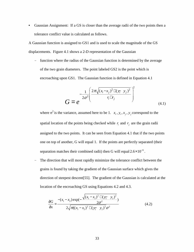
• Gaussian Assignment: If a GS is closer than the average radii of the two points then a
tolerance conflict value is calculated as follows.
A Gaussian function is assigned to GS1 and is used to scale the magnitude of the GS
displacements. Figure 4.1 shows a 2-D representation of the Gaussian
- function where the radius of the Gaussian function is determined by the average
of the two grain diameters. The point labeled GS2 is the point which is
encroaching upon GS1. The Gaussian function is defined in Equation 4.1
22 2
2
2 ( ) ( )1
2
i j i j
i j
x x y y
r r
G e
π
σ
− + − − + = (4.1)
where σ2 is the variance, assumed here to be 1. ix , iy , jx , jy correspond to the
spatial location of the points being checked while ir and jr are the grain radii
assigned to the two points. It can be seen from Equation 4.1 that if the two points
one on top of another, G will equal 1. If the points are perfectly separated (their
separation matches their combined radii) then G will equal 92.6 10−× .
- The direction that will most rapidly minimize the tolerance conflict between the
grains is found by taking the gradient of the Gaussian surface which gives the
direction of steepest descent[55]. The gradient of the Gaussian is calculated at the
location of the encroaching GS using Equations 4.2 and 4.3.
2 21 2 1 2
1 2 2
2 2 21 2 1 2
( ) ( )( )exp( )
22 (( ) ( )
x x y yx xG
x x x y y
σπ σ
− + −− − −∂ =
∂ − + − (4.2)

34
Figure 4.1: 2-D Gaussian function centered at GS1 and showing overlapping GS2.

35
2 21 2 1 2
1 2 2
2 2 21 2 1 2
( ) ( )( )exp( )
22 (( ) ( )
x x y yy yG
y x x y y
σπ σ
− + −− − −∂ =
∂ − + − (4.3)
- The direction vectors are then converted into unit vectors. This vector is then
scaled by the previously calculated magnitude of the Gaussian and stored for
future use as a conflict vector.
• Loop through each point: This process is repeated until the conflict vectors for each
point have been calculated. GS with more than one conflict vector have their vectors
summed together to produce a composite conflict vector that gives the direction that
will minimize GS overlap.
• Normalize: At this stage of the process, each GS has a vector assigned to it that will
define the direction and the relative magnitude of the GS displacement. Prior to
displacing the grains the vectors must be normalized as they were defined irrespective
to any scale. To do this, the vector with the maximum magnitude is found and used
as a scaling factor for the displacement of all other grains. After scaling, the vector
magnitudes are all less than or equal to one. These vectors are again scaled to
incorporate the length scale of the problem. This final scaling factor is 1/100 of the
average grain diameter.
• Displacement: GS are displaced according to their displacement vectors.
• Iterate: The entire process is then repeated until the system reaches a local minimum
overlap value.

36
Snapshots of this process are shown in Figure 4.2 through Figure 4.5. These figures
show the GS after progressively more displacement iterations. The arrows denote the
direction in which the points will be displaced and are proportional to the magnitude of
the displacement. By the 100th iteration, an obvious structure can be seen. The domain
shown in these figures was specified to have 30% porosity. The porosity is
manifested as the clusters of GS interspersed with the larger GS.
Because grain placement is an explicit process (stepping forward), the size of
each step is important. If the points are moved a large distance (corresponding to a large
final scaling factor) in one iteration, they will not converge to a local minimum.
However, if the points are moved too small a distance, the number of steps to
convergence will grow and increase the run time of the code.
Figure 4.6 is a plot of overlap magnitude versus iterations, and illustrates
convergence behaviors of different step sizes. Each step size corresponds to the mean
grain diameter multiplied by a scaling factor. Once the optimum scaling factor is
determined, it can be used for a domain containing grains of any diameter. The pink line
corresponds to the largest step size tested and demonstrates that convergence will not
occur when the scaling factor becomes too large. The lack of convergence is expected as
grains will not be able to take the gradual steps to convergence. Instead, they will be
moved with large displacements that do not minimize the tolerance conflicts between
grains. As the scaling factor decreases, the energy converges quickly in less than 100
steps. As expected, when the step size is decreased further, the overlap continues to
converge, but requires many more steps. Figure 4.6 shows that a scale factor ranging
between 1 and 0.1 produces the fastest convergence.

37
Figure 4.2: Grain sites shown after initial overlap checking. Vectors represent the direction of displacement.
Figure 4.3: Grain sites shown after 20 displacement iterations.

38
Figure 4.4: Grain sites shown after 40 displacement iterations.
Figure 4.5: Grain sites shown after 100 displacement iterations. Patterns can now clearly be seen in the grain sites.

39
Figure 4.6: Overlap energy as a function of iterations. Each line shows different maximum step sizes which correspond to the mean grain size multiplied by a scaling factor. As step size increases, the convergence rate increases until a point at which
convergence no longer occurs.

40
Because GS greater than their average diameter apart do not interact, a significant
performance increase can be attained by selectively checking for tolerance conflicts. A
minimal checking option was created to segment the target into several smaller domains.
Segmenting the target enables the large domain to be bisected into smaller domains
which have an edge length equal in size to that of the maximum grain diameter. When
bisecting the domain in this manner, points need only be checked against sites located
within their specific domains and with the sites in adjacent domains (Figure 4.7). The
orange colored box contains sites being checked for tolerance conflicts and the green
boxes contain points which can possibly interact with those in the orange box.
To demonstrate the increase in speed, 356 GS and 1485 void sites were subjected
to 1000 iterations. When the selective checking algorithm was implemented the domain
was segmented into 169 small domains and ran for approximately 17 seconds. Without
selective checking the algorithm ran for 194 seconds, an increase of nearly 11.5 times.
This difference in run time is dramatic and increases with the number of GS that are
placed. One unfortunate property of this type of domain sorting is that with increasing
grain size distribution, the improvements are diminished as sub-domains must not be
smaller than the largest grain radii.

41
Figure 4.7: Large domain segmented into smaller sub domains. The orange box contains points that are being checked and the green boxes contain points that can interact with the
points in the orange box.

42
4.2.2 Modified Voronoi Tessellation
The second major process in the generation of the sand grains uses a VT.
A VT is a process that can be used to bisect a space into a set of unique subspaces[54].
Figure 4.8 shows a simple schematic of the tessellation process. In Figure 4.8 A the
grains sites that are to be tessellated are displayed. In this schematic view only the site
located in the center will be tessellated. The initial step in the tessellation determines the
nearest sites relative to the site being tessellated (see Figure 4.8B). Next, bisecting lines
are created at the midpoints between the center site and the contributing sites as seen in
Figure 4.8C. These bisecting lines and their intersections, called Voronoi points (VP)
make up the tessellation of the center grain which, in this case, takes the form of the
octagon in Figure 4.8E. This process can be performed on any arrangement of points
with the only restriction being that the points do not lie directly upon one another.
Figure 4.9 shows the tessellation of the GSs in Figure 4.5 and demonstrates the
capability of the tessellation process. The tessellation shown in Figure 4.9 contains
grains sites as well as void sites and highlights one aspect of the VT that is not desirable.
Due to the way in which the Voronoi tessellation is produced (perpendicular bisectors),
there is an averaging effect between bordering large and small grains. When a small cell
is in contact with a large cell the two are distorted so that the large cell loses area and the
small cell gains area. In order to minimize this effect, the tessellation goes though an
augmentation process which relocates the Voronoi points to best match the surrounding
GS tolerances.

43
Figure 4.8: Schematic of steps used to produce a Voronoi tessellation. A: Points that will be tessellated, B: Neighbor search to define contributing points, C: Bisection of lines connecting contributing points. D: Location of bisector intersections, E: Final tessellation
A
E
C D
B

44
Figure 4.9: VT of sites generated with ISP-SAND. Dots represent the sites and the lines represent the VT. In this domain, the small sub zones will be removed to yield a porous sample. Notice that the tessellation has an averaging effect on the grain size. Grains and voids that border one another have been distorted in a way that decreases the grain size
and increases the void size.

45
The augmentation is carried out with an iterative approach that converges to a minimum
residual error. Figure 4.10 shows the difference between the Voronoi tessellation (green)
and the post augmentation tessellation (blue). In this case, GS1 was assigned a smaller
radius during point placement than GS2 and GS3. However, because a tessellation is
created irrespective of the point radii the Voronoi cells are distorted and not of the correct
size. The process to enforce the grain radii is as follows:
• The association between each GS and VP are found. In Figure 4.10, the VP is
associated with GS1, GS2, and GS3 because it lies on the boundaries of their
Voronoi cells.
• The distance D between each GS and the VP are checked against the grain site
radii to produce error terms for each GS and VP pair. The error term E between
GS1 and the VP is displayed in Equation 4.4,
2 2
1 1( 1 ) ( 1 )GS VP x x y y GSE GS VP GS VP r− = − + − − (4.4)
where the subscripts denote the x and y coordinate of the points.
• A unit vector parallel to a line connecting the VP and GS is created and scaled by
the error term E.
• The error vectors created for each VP are added together and the final error vector
is non-dimensionalized by the minimum grain diameter multiplied by .01.
• Each VP is then moved according to the corresponding composite error vector.
• The process of moving this point is repeated until the error vector becomes
approximately 0 denoting a minimum error between all the surrounding GS and
the VP.
• The process is then repeated for each VP.

46
The end result of this process can be seen in Figure 4.11. In this augmented tessellation,
grain sites as well as void sites are easily distinguishable and match the input diameters
reasonably well (to be demonstrated later).
Two difficulties were discovered with the augmentation process. First, the process is
capable of producing overlapping grains. This problem was simply solved by combining
the two overlapping points and submitting the new site to the augmentation algorithm.
Second is the issue of concave grains. Concavity can be found in real sand grains [49,
50] and increases the likelihood of a grain folding upon itself [51]. This cannot currently
be simulated with ISP-TROTP. This problem is addressed by simply removing the point
causing concavity from the target. The result of this is straight faces where the concave
portions previously occurred. This simple solution works well when concavity is
minimal. However, strangely shaped grains can be produced when concavity is extreme.
In this process, concavity is associated with the breadth of the size distribution between
placed points and can be minimized by keeping the size difference between GS and VS
relatively small. Void sites that are ¼ the size of the grains produce reasonable porosity
results. As can be seen in Figure 4.11, concavity does not appear, even when grains are
surrounded by voids 25% of their size.
As with the GS placement in the previous step, the tessellation process can be
made more efficient by only considering the points closest to the point being tessellated.
To implement this strategy, the same approach is taken as in the grain placement
algorithm of dividing the domain into a set of smaller domains. The sizing of these
domains is not as straightforward as in the grain placement process. This is because there
is not an exact criterion for point interaction. Points which may interact in the

47
Figure 4.10: Optimization of Voronoi tessellation. The VP is shifted to minimize the difference between the assigned radius of the GS and the distance between the GS and
the VP.

48
Figure 4.11: Modified VT of sites generated with ISP-SAND. Grain and void sites are clearly visible. Grain sites are expanded to their assigned diameters and void sites have
been condensed to their assigned diameters.

49
tessellation could be farther away than their average grain diameters. To ensure an
adequate sub domain size, the sub domains were given dimensions twice the size of the
largest grain diameter. To validate the adequacy of the sub domain size, a number of
cases were run comparing tessellations with and without the smaller sub domains. Each
case was found to yield the same tessellation. This algorithm increased the speed of
tessellation immensely. For example, when a tessellation of 3,183 uniform sized grains
was completed, the tessellation which divided the domain created 576 boxes and took 5
seconds. The undivided domain took approximately 180 seconds. The necessity of this
optimization grows with the number of grains being tessellated. The sub domain size is
dependent upon the largest grain in the domain. Unfortunately, the algorithm
effectiveness diminishes with increased grain size distribution or with a small number of
large grains in the domain.
With the tessellation phase completed the void grains are removed from the
target, and VP that are closer together than that the desired mesh size are combined.
Combining points is a necessary step to ensures that the finite element mesh will not be
excessively small in any location. After these two steps, the sand generation is complete
and ready for mesh generation.
4.2.3 Mesh Generation
These simulations used constant strain triangles which were created in one of two
ways. If a course mesh was desired, a simple algorithm was used which connected the
centroids of the grains to each of their associated VPs, as shown in Figure 4.12. This can
produce mesh elements that are elongated wedges if the grain has more than six divisions

50
around its circumference or is distorted. If a refined mesh was desired, Sandia National
Laboratories code Cubit 9.1 was used. Initially, meshing with Cubit was found to be
slow (possibly greater than 24 hours for 20,000 grains) and unreliable (caused the
workstation to crash). However, a substantial speed increase was achieved by meshing
each grain individually and disabling Cubits display window. This process was
completed by creating a script file for each grain. These script files were then executed
in Cubit and produced a small mesh file for each sand grain. The small files are then
processed and combined to create the final mesh. Meshing in this way enables Cubit to
complete a job of 20,000 grains in approximately 1 hour and also gives it the ability to
create meshes with millions of elements. An added benefit is that numerous copies of
cubit can work on the same sand target, enabling the efficient use of a multi-core
workstation. A mesh produced in this manner is displayed in Figure 4.13.

51
Figure 4.12: Mesh produced by connecting VPs to grain centers of area.
Figure 4.13: Tridelaunay mesh created using Cubit 9.1.

52
4.2.4 Process Validation
Due to the complexity of the process described above, it is necessary to compare
the initial specifications for the target with those produced in the finished product. The
two parameters that were initially specified were the grain size and target porosity. Grain
size is found by calculating the area of the grain and making the approximation that the
grain is equiaxed [56]. This allows for the diameter of the grain to be calculated using
the simple area of a circle equation4A
Dπ
= . Target porosity is calculated by
subtracting the total area of the grains from the rectangular target area as follows in
Equation 4.5
T G
T
A Ap
A
−= (4.5)
where AT is the area of the target and AG is the combined area of the grains.
One test to demonstrate the code capability was to input a uniform grain size and
a specified porosity value. In this case, a grain diameter of 60µm and a porosity of 30
percent were used with the over all target size specified as a 5mm by 5mm box. The
finished target contained 6189 grains and a porosity of 30.32 percent. The mean diameter
of the grains was 59.87, and the grain size distribution is shown in Figure 4.14. The
distribution shown in Figure 4.14 has a standard deviation of 1.73µm assuming that a
normal distribution, about 68%[55] of the grains, lie within plus or minus 1.73µm of the
mean diameter. The sand grains produced in this test can be seen in Figure 4.15.

53
Figure 4.14: Grain size distribution for input of 60µm grain size. The mean grain size is 59.87 and shows close correspondence to input parameters.
Figure 4.15: 60µm uniform grains

54
A second test of the validity involves a target with a distributed sand size. In this
example, the porosity is again specified as 30 percent but instead of specifying a constant
grain size, grains ranging in diameter from 45 – 75 µm are specified. The finished 5mm
by 5mm target contained 6189 grains and had a porosity of 29.84 percent. When the
grain sizes were calculated, the distribution shown in Figure 4.16 was produced. The
grain size distribution had a standard deviation of 8.7 from the mean diameter of
60.07µm, which as expected, is much larger than the uniform grain size standard
deviation. The sand grains in this target can be seen in Figure 4.17.
The above two tests demonstrate that for targets with 30% porosity and moderate
grain size distributions, ISP-SAND produces targets with correct grain sizes and
porosities.

55
Figure 4.16: Grain size distribution for input of 45 -75um grain size. The mean grain size is 60.07um and shows close correspondence to input parameters
Figure 4.17: Grains ranging in size from 45 – 75 um

56
4.2.5 Regular and Irregular Grain Placement
Experimental characterization of sand samples can produce data on grain size and
sample porosity[56]. These two properties are bulk parameters and can be satisfied by an
infinite number of sand grain layouts. Without any modifications, ISP-SAND produces
targets with grains that are clustered together producing relatively large concentrations of
grains surrounded by large porous regions as can be see in Figure 4.15 and Figure 4.17.
To study the effects of targets with less grain clustering, a small change was made to ISP-
SAND. The addition was made to the grain placement algorithm and it changed the way
in which grains were placed in the target. In the standard technique, grains were initially
placed randomly throughout the target. When the change was implemented, the target
was divided into N subsections where N is the number of grains. Within each subsection,
one grain was randomly placed and V/N void sites were placed where V is the number of
void sites. If the target could not be divided evenly, extra points were randomly placed in
the target.
When this change was implemented, grains still satisfied the bulk distribution and
porosity parameters but were more dispersed than before. A test case is shown here with
the same parameters as given previously with 45-75 µm grains. The grain size
distribution in the 5mm by 5mm target can be seen in Figure 4.18 and compares closely
to the distribution shown in Figure 4.16. The target was calculated to have a porosity of
29.5% and a mean grain size of 60.19µm. The standard deviation of this distribution is
8.6µm which is close to the standard deviation in the non distributed grains. Figure 4.19
shows the actual grains that were produced. Comparing Figure 4.19 with Figure 4.17
shows that grains are more evenly spread and large clusters of grains no longer occur.
57
Grains produced when this algorithm was implemented will be referred to as regular
grains otherwise the grains will be referred to as clustered.
4.2.6 ISP-SAND Conclusion
ISP-SAND was tested and it demonstrated the ability to produce large numbers of
grains (in excess of 1,000,000) that can reproduce input grain sizes and porosities. ISP-
SAND can produce different grain layouts in which grains can either be clustered or
evenly spread throughout the target. By changing the initial random seed used in the
grain placement algorithm, the code is able to produce an infinite number of different
targets with relatively similar bulk parameters.
4.3 Projectile Properties
The projectile used in the simulations, shown in Figure 4.20, was a tip modified
3.5 caliber radius head (CRH)[35] tangent ogive[34] projectile with a l/d ratio of 3.85.
The tip of the projectile is modified so that θ = 60º. This modification was completed to
limit the deformation at the projectile tip. Similar modifications can be seen in the
literature[57, 58]. The projectile, like the grains, was meshed using Cubit 9.1. A number
of different meshing schemes were compared and Tridelaunay was determined to be
optimal. This assertion was made as no mesh biasing and only minimal mesh seams (two
seams can be seen formed at the back end of the projectile) were produced. The mesh
used on the projectiles is the same size as that used on the grains and consists of triangles
with edge lengths of approximately 10µm.

58
Figure 4.18: Grain size distribution for input of 45-75µm grain size. These grains were placed initially in a more normal way than those seen in previous tests.
Figure 4.19: Grains ranging in size from 45-75 µm with more homogeneous porosity and grains.

59
Figure 4.20: Tangent ogive projectile with 10um triangular mesh.
D
L
θ
θ

60
SECTION 5 Results and Discussion Results and Discussion
This section displays and discusses the results from the numerical simulations. In
most cases, snap shots of the penetrator and surrounding sand grains will be displayed
after one full depth of penetration. These plots will be discussed and the important
features found in them will be described. Plots of the instability parameters calculated
during the penetration will be displayed and the various differences seen between
simulations will be highlighted. For each simulation the average lateral force applied to
the projectile and the final x displacement for the projectile are displayed in Table 5.1
5.1 1-3 Baseline Simulations (inelastic grains, plastic impactor at three velocities)
The baseline simulations, 1-3, considered elastic-plastic projectiles and inelastic
sand grains. The targets were all identical and had a porosity of approximately 30%.
Sand grains ranged in size between 45-75µm. Inter-granular friction was implemented
using a Coulomb friction law with a coefficient of µ=.3. Snapshots of these simulations
at one depth of penetration (except the 1000 m/s case) are shown in Figure 5.1 and Figure
5.2. These figures show the same three simulation results with different contour values
being displayed. The 1000 m/s simulation did not achieve a full depth of penetration due
to a contact problem in ISP-TROTP. It is shown at its deepest penetration prior to the
contact problems (approximately 60% of one penetration length).

61
Figure 5.1: Plastic penetrator entering inelastic grains at, left 500 m/s, center 1000 m/s, right 1500 m/s. Showing contours of Y velocity, X velocity, and effective stress.

62
Table 5.1: List of simulations displaying average lateral forces and final x displacements.
Grain Size
Projectile Velocity (m/s)
Projectile Type
Grain Type Placement Porosity
Friction (µ)
Average Lateral Force (N)
x Diplacement (mm)
1 42-78 µm 500 Plastic Plastic Regular 30% 0.3 2950 0.0053 2 42-78 µm 1000 Plastic Plastic Regular 30% 0.3 -38800 -
3 42-78 µm 1500 Plastic Plastic Regular 30% 0.3 -35390 0.0055 4 42-78 µm 500 Elastic Plastic Regular 30% 0.3 2850 0.0003
5 42-78 µm 1000 Elastic Plastic Regular 30% 0.3 -19650 0.0004 6 42-78 µm 1500 Elastic Plastic Regular 30% 0.3 -58630 0.0054
7 42-78 µm 1500 Plastic Elastic Regular 30% 0.3 105000 0.0062 8 42-78 µm 1500 Elastic Elastic Regular 30% 0.3 11240 0.0013
9 60 µm 1500 Plastic Plastic Regular 30% 0.3 25980 0.0062 10 60 µm 1500 Elastic Plastic Regular 30% 0.3 102200 0.0157
11 84-156 µm 1500 Plastic Plastic Regular 30% 0.3 67350 0.0126 12 84-156 µm 1500 Elastic Plastic Regular 30% 0.3 63800 0.0176
13 42-78 µm 1500 Elastic Plastic Regular - 2 30% 0.3 17720 0.0035 14 42-78 µm 1500 Elastic Plastic Regular - 3 30% 0.3 -73590 0.0020
15 42-78 µm 1500 Elastic Plastic Regular - 4 30% 0.3 41660 0.0045 16 42-78 µm 1500 Elastic Plastic Regular - 5 30% 0.3 37950 0.0039
17 42-78 µm 1500 Plastic Plastic Clustered 30% 0.3 -23670 0.0094 18 42-78 µm 1500 Elastic Plastic Clustered 30% 0.3 -130700 0.0147
19 42-78 µm 1500 Plastic Plastic Regular 40% 0.3 56280 0.0054 20 42-78 µm 1500 Elastic Plastic Regular 40% 0.3 -30890 0.0012
21 42-78 µm 1500 Plastic Plastic Regular 30% 0.0 46200 0.0035 22 42-78 µm 1500 Elastic Plastic Regular 30% 0.0 13510 0.0001 3 Depths of penetration 23 42-78 µm 1500 Elastic Elastic Regular 30% 0.3 24 42-78 µm 1500 Elastic Elastic Regular 30% 0.0 Variable mass simulations 25 42-78 µm 1500 Elastic Plastic Regular 30% 0.3 Mass Multiplied by 2 26 42-78 µm 1500 Elastic Plastic Regular 30% 0.3 Mass Multiplied by 1/2

63
Figure 5.2: Plastic penetrator entering inelastic grains at, left 500 m/s, center 1000 m/s, right 1500 m/s. Showing contours of X Stress, Y Stress, and shear stress.

64
5.1.1 Inelastic Deformation of the Projectile
A notable feature in Figure 5.1 and 5.2 is the increasing inelastic deformation of
the projectile with increasing velocity. The type of deformation shown here has been
seen by Forrestal et al. [58] who conducted reverse ballistic shots using a gas gun. In
Forrestal’s work, foundry core impactors were fired at tungsten projectiles and showed
increasing deformation with impact velocity. However, this large mushrooming effect is
likely not physical in semi infinite target penetration as a number of other authors do not
report such deformation [1, 7, 9, 11, 14].
The large projectile deformation could be caused by a number of factors. One
reasonable explanation may be a flaw in the material models being used. As stated
previously, the material model for a sand grain is not known. Another explanation may
be the lack of projectile erosion and grain fracture. Neglecting erosion and failure may
affect the penetration resistance of the media and lead to the greater than expected
deformations. A third cause of the deformation may be an effect of the 2-D geometry. 2-
D simulations may constrain the sand to displace under the projectile in only two
directions. This may lead to a media that is more difficult to penetrate.
Whatever the cause of the deformation, it can be understood as a self-proliferating
process. As the penetrator becomes deformed, its tip broadens and the amount of
material which must be displaced increases. This further increases the penetration
resistance and the inelastic deformation of the penetrator. To study the effects of target
parameters without such large projectile deformations, each simulation used both
inelastic and elastic projectiles.

65
The deformed projectile in the 1500 m/s case has taken on a wedge shape that is
not centered at the projectile axis. This strange deformation is characteristic of a mesh
effect. To check if this feature was a mesh based effect an alternate simulation was
performed. In this alternate simulation, the projectile mesh was changed by using a
different Cubit meshing algorithm. When the second simulation was completed, the
deformation fields were similar and the wedge point on the deformed projectile occurred
at the same location. Upon examining step by step simulation snap shots it was found
that during the simulation, a region of empty space formed under one portion of the
projectile and caused the formation of this deformed tip. This shows that this
deformation is not merely a mesh effect but caused by the sand target.
5.1.2 Stress Fingers
Another qualitative feature shown in Figure 5.1 and Figure 5.2 is the presence of
stress fingers. Stress fingers are commonly seen in granular materials [59, 60] and are
caused by networks of individual grains which line up and transmit stresses along their
length. Stress fingers may be an important indicator of instability as they are a direct
evidence of the inhomogeneous loads placed on the projectile. When grains are not
symmetrically placed around the impactor, differences will be manifested in the size of
the stress finger networks. Large stress chain networks allow for the efficient
transmission of stresses away from the projectile and will result in the application of
increased loads on the sides of the projectile. This may cause deviation from the path and
result in projectile bending.
Another feature of interest is the deformation zone around the penetrator.
Unfortunately, the 1000 m/s simulation terminated early. Comparing the zones in the

66
500 and 1500 m/s cases is still informative. The affected zone in the 500 m/s case is
larger than in the 1500 m/s case. This is reasonable as the grains have had three times as
much time for displacment in the lower velocity simulations. This added displacement
time may help to stabilize the projectile as the grains have had added time to become
more homogonous.
5.1.3 Instability Measures
As previously discussed, a number of quantitative measures were used to gauge
projectile instability. Figure 5.3 shows the lateral forces in kilonewtons incurred by the
projectiles in the 500 and 1500 m/s simulations. From this figure it can be seen that the
500 m/s projectile experiences smaller lateral forces than the 1500 m/s projectile. Also,
forces are applied evenly to both sides of the 500 m/s projectile while this is not the case
in the 1500 m/s projectile. This is demonstrated by the average lateral force applied to
the projectile throughout the simulation, presented in Table 5.1. The average lateral force
applied to the 1500 m/s projectile is more than an order of magnitude larger than that
applied to the 500m/s projectile.
The total projectile deviation from its path after one depth of penetration can also
be used as a measure of instability. These values are displayed in Table 5.1. In this case,
the deviation from the path for the two projectiles is relatively close. However, the
deviation from the path in these simulations is obscured and may not implicate instability
but rather the large asymmetric deformation of the 1500m/s projectile.
Another measure of instability, the projectile rotational momentum, is shown in Figure
5.4. Examining the projectile rotational momentum shows that, increasing projectile
velocity results in increasing rotational momentum. The rotational momentum shown is

67
again obscured by the large inelastic deformation of the projectile. However, the trend of
increasing instability with increasing velocity remains when considering elastic
projectiles.
5.2 4-6 Baseline Simulations (inelastic grains, elastic impactor at three velocities)
As just discussed, elastic-plastic penetrators display an unrealistic amount of
mushrooming. To investigate the stability of projectiles which retain their original shape,
plastic deformation was removed artificially by increasing the yield strength of the
projectile material. Figure 5.5 and Figure 5.6 shows various contour plots for simulations
4-6. These simulations again show the “finger” effect seen in the elastic/plastic
simulations. In these simulations, the highest stresses are focused at the projectile tip and
are more localized than in the case with the highly deformed penetrator. Comparing
simulations 3 and 6 shows that the affected zone size around the projectile is similar in
size, but the elastic projectile has penetrated into the highly stressed grains while the
plastic penetrator has deformed laterally.
The deformation in the affected zones of the high velocity simulations can be
qualitatively compared with experiments shown by Grantham et al. [61] who tracked the
deformation fields produced during penetration using speckle correlation methods.
Speckle correlation is a technique using X-ray detectable particles (lead) imbedded in a
media which can be tracked using X-ray cameras and correlation software. This method
allowed the authors to study the deformation fields around flat nosed projectiles during
penetration experiments into sand at 1500 m/s. Grantham’s experiments have features
that are qualitatively similar to these simulations and show material flowing initially

68
Figure 5.3 Lateral forces on the plastic penetrator from simulations 1 and 3 show large lateral forces at increased penetration velocity.

69
Figure 5.4 Rotational Momentum curves corresponding to the projectiles in simulations 1-3

70
Figure 5.5 Elastic penetrator entering inelastic grains at, left 500 m/s, center 1000 m/s, right 1500 m/s. Showing contours of Y velocity, X velocity, and effective stress.

71
Figure 5.6: Elastic penetrator entering inelastic grains at, left 500 m/s, center 1000 m/s, right 1500 m/s. Showing contours of X Stress, Y Stress, and shear stress.

72
vertically with the projectile and then laterally outwards as the projectile continues to
move into the media.
In these simulations, there is a region of highly stressed and compressed grains
directly under the undeformed projectile tip. The location of this region is far away from
the projectile center of mass. Because of this, the forces created by this region on the
projectile have a large moment arm, and the ability to impart large changes in rotational
moment to the projectile. This effect is seen in Figure 5.7 and can be compared with the
rotational momentum of the plastic projectile fired into the same medium shown in
Figure 5.4.
Lateral forces applied to the projectile through out the simulations were plotted
for these simulations and can be seen in Figure 5.8. Similar to simulations 1-3, lateral
forces increase with projectile velocity showing an increased tendency towards instability
at high velocities. Also, with increasing velocity the forces become less centered about
the zero axis. The average lateral forces on the projectile show that increasing
penetration velocity causes the forces to become more focused on one side of the
projectile than the other. This can be seen by comparing the average lateral forces in
Table 5.1.

73
Figure 5.7 Rotational momentum curves corresponding to the projectiles in simulations 4-6 showing greater instability at higher velocities

74
Figure 5.8: Lateral forces applied to elastic projectile in runs 4-6. Forces increase significantly with velocity

75
5.3 Effect of Sand Grain Strength:
To investigate the effects of grain strength on instability, two cases were
considered in which the grains were defined as an elastic material (simulations 7 and 8 in
Table 5.1). Plots at one depth of penetration showing velocity and effective stress
contours are shown in Figure 5.9. Rotational momentum for these two cases is displayed
in Figure 5.10.
In simulation 7 it can be seen that penetration resistance has increased and caused
larger deformation if the projectile than in the case considering inelastic grains. In
simulation 8, there is a focused region of stressed grains under the penetrator tip;
however, to a lesser extent than in case 6 with elastic projectile and inelastic grains. This
is notable because the penetrator shows less instability and may allude to one cause of
instability: the formation of non-centered accumulation of compacted soil particles under
the projectile tip. This type of formation would increase the amount of off-axis forces on
the projectile and cause instability.
The rotational momentum plots show that the projectiles in these simulation are
relatively stable as compared to the previous case with inelastic grains. In this case, the
elastic-plastic projectile has received a relatively large amount of rotational momentum
as compared to the elastic penetrator case. However, this can again be explained by the
large asymmetric plastic deformation experienced by the projectile. The rotational
momentum of the elastic projectile remains low when compared to the previous cases.
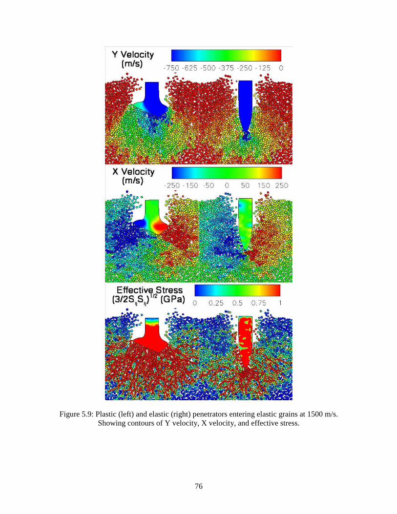
76
Figure 5.9: Plastic (left) and elastic (right) penetrators entering elastic grains at 1500 m/s. Showing contours of Y velocity, X velocity, and effective stress.
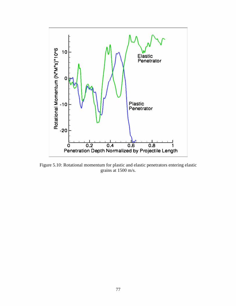
77
Figure 5.10: Rotational momentum for plastic and elastic penetrators entering elastic grains at 1500 m/s.

78
5.4 Effect of Grain Size and Grain Size Distribution:
Sand grains have different shapes and sizes. To probe the effects of grain size
distribution, simulations 9 and 10 were performed with a uniform 60µm grain size. An
interesting result occurred in simulation 10, as shown in Figure 5.11. It seems that the
grains were not able to shift and move as easily as in the distributed grain size case. This
effect is manifested in the large cluster that formed under the projectile tip.
It is clear that some numerical effects occur that influence the cluster size and
shape. At this point, it is unlikely that grains would have failed (fracture). This said, the
simulation can be compared with the case considering distributed grains. Although the
same type of clustering occurs in both cases, the cluster size is much larger in this case.
As seen in Figure 5.11, the large cluster happens to be off axis from the projectile and
creates a large lateral force on the projectile as seen in Table 5.1. The rotational
momentum of the projectile seen in Figure 5.12 also shows the effects of this large cluster
as a large increase in projectile rotational momentum.
In these simulations, the effects of grain size was found to have a marked effect
on instability. In simulations 11 and 12, projectiles were fired into grains ranging
between 84 – 156 µm. As seen from the angle of projectile tilt in Figure 5.11, the larger
grains produce an increased amount of instability. The instability caused by the large
grains is comparable to the instability caused in the case of uniform grains, even though a
large grouping of grains does not form.

79
Figure 5.11: showing contours of effective stress Left: Elastic Penetrator into inelastic 60µm uniform grains (Run 10), Right: Elastic Penetrator into 84-156 µm grains (Run 12)

80
Figure 5.12: Rotational momentum curves for A: Elastic penetrator entering inelastic 60µm uniform grains (Run 10), B: Elastic penetrator entering inelastic 84-156 µm grains
(Run 12)

81
5.5 Effect of Random Placement of Sand Grains:
To probe the effects of variations in grain placement, simulations 13 – 16 were
completed. These simulations consider elastic projectiles with initial velocities of 1500
m/s. Targets have similar porosity and grain size distributions are those in simulation 6
but have a different granular arrangement. Three snapshots of these simulations are
displayed in Figure 5.13 and can be compared with Figure 5.5. All the simulations have
similar “finger” patterns and show variable amounts of rotational momentum displayed in
Figure 5.14. As expected, these simulations demonstrate that different arrangements of
sand particles affect the simulation results. However, instability seems to still occur
regardless of the granular layout.
To further examine the effects of grain placement, targets were modified to
produce grains with the same porosity and size distribution as before: but with larger
clusters of sand grains and larger regions of empty space. These grains can be seen in
Figure 4.17. The rotational momentum results for these simulations (17 & 18) displayed
in Figure 5.15 show increased instability when compared to the cases with a more
uniform distribution of grains and porosity.

82
Figure 5.13: Elastic penetrators fired into 42-78µm targets with random seed variation,
showing contours of effective stress. Runs 13, 15, and 16.

83
Figure 5.14: Rotational Momentum of 5 projectiles fired into targets with similar grain
sizes and porosities.

84
Figure 5.15: Rotational momentum of penetrators fired into clustered grains. Showing 1: Plastic Penetrator (Run 17) and, 2: Elastic Penetrator (Run 18)

85
5.6 Effect of Porosity: The porosity of sand is variable. To examine the effects of target porosity two
simulations were given with 20% and 40 % porosity. Upon testing the 20% porous
targets deformation was so severe the simulations could not be completed. Simulations
involving 40% porous targets can be seen in Figure 5.16 and are given as simulations 19
and 20. The plastic projectile shows less deformation than the 30% porous simulation
shown in Figure 5.5. Also, stress and deformation fields surrounding the projectile are
greatly reduced. Figure 5.17 shows the rotational momentum of the projectiles. It can be
seen that the elastic projectile displays less instability than in simulation 6 considering
targets with 30% porosity.
Figure 5.16: plots showing effective stress at one depth of penetration in 40% porous target Left: Plastic Projectile (Run 19), Right: Elastic Projectile (Run 20)

86
Figure 5.17: Rotational Momentum curves for plastic and elastic projectiles penetrating
40% porous targets.

87
5.7 Effects of Friction:
The frictional coefficient acting between grains during high speed sliding is not
known. Friction [62-64] can be governed by a number of effects including surface
roughness, contact velocity, localized heating, etc. For this reason, in all other cases a
constant friction coefficient of .3 was used. To examine the effects of friction,
simulations 21 and 22 were performed with frictionless grains and penetrator. The
simulations shown in Figure 5.18 behave much like the higher porosity simulations.
Deformation of the elastic-plastic projectile was reduced and the instability in the elastic
projectile was reduced as demonstrated by the rotational momentum shown in Figure
5.19. One apparent feature is the relative lack of stress fingers. Compared with previous
cases (Figure 5.13) these two runs show fewer long stressed chains of material
demonstrating a more homogeneous target ahead of the projectile.
Figure 5.18: Plots showing effective stress at one depth of penetration in frictionless targets Left: plastic projectile (simulation 21), Right: elastic projectile (simulation 22)

88
Figure 5.19: Rotational momentum plots of plastic and elastic projectiles penetrating frictionless targets

89
5.8 Deep Penetration Results Up to this point only one depth of penetration has been considered. It has been
shown that a single depth of penetration is enough to show the onset of instability.
However, in pursuit of further evidence of instability, two simulations were performed
that incorporated approximately 3 penetration depths. These simulations have over
20,000 grains and 800,000 finite elements. Because computation time becomes an issue
with simulations of this magnitude, the two runs consider elastic penetrators and elastic
grains. The target consisted of 42-78 um grains with a porosity of 30%. The only
difference between the two runs was the coefficient of friction which was 0.0 and 0.3.
These two runs can be seen in Figure 5.20. The effect of friction on instability is quite
apparent as the frictional penetrator on the right has tilted to almost a 30 degree angle.
Rotational momentum plots shown in Figure 5.21 show that in the frictional case the
projectile gains rotational momentum at a rate grater than the projectile in the frictionless
case. This leads to the projectile in the frictional case having a greater angle of tilt than
in the frictionless case. Tilted projectile are direct evidence of projectile instability.
5.9 Examination of the Oscillations An interesting feature can be found in many of the rotational momentum plots that
consider elastic projectiles impacting at 1500 m/s. This feature is a periodicity in the
rotational momentum seen in Figures 5.7, 5.10, 5.12, 5.14, 5.17, and 5.21. Periodicity
can also be seen in the lateral force plots shown in Figure 5.8. In each plot, the
periodicity was seen to occur at roughly the same frequency. Thus, the oscillations may
correspond to the properties and geometry of the penetrator.

90
Figure 5.20: Deep penetration runs showing contours of effective stress, considering an elastic penetrator and elastic grains. A: frictionless penetration displays little instability
B: frictional penetration shows instable behavior
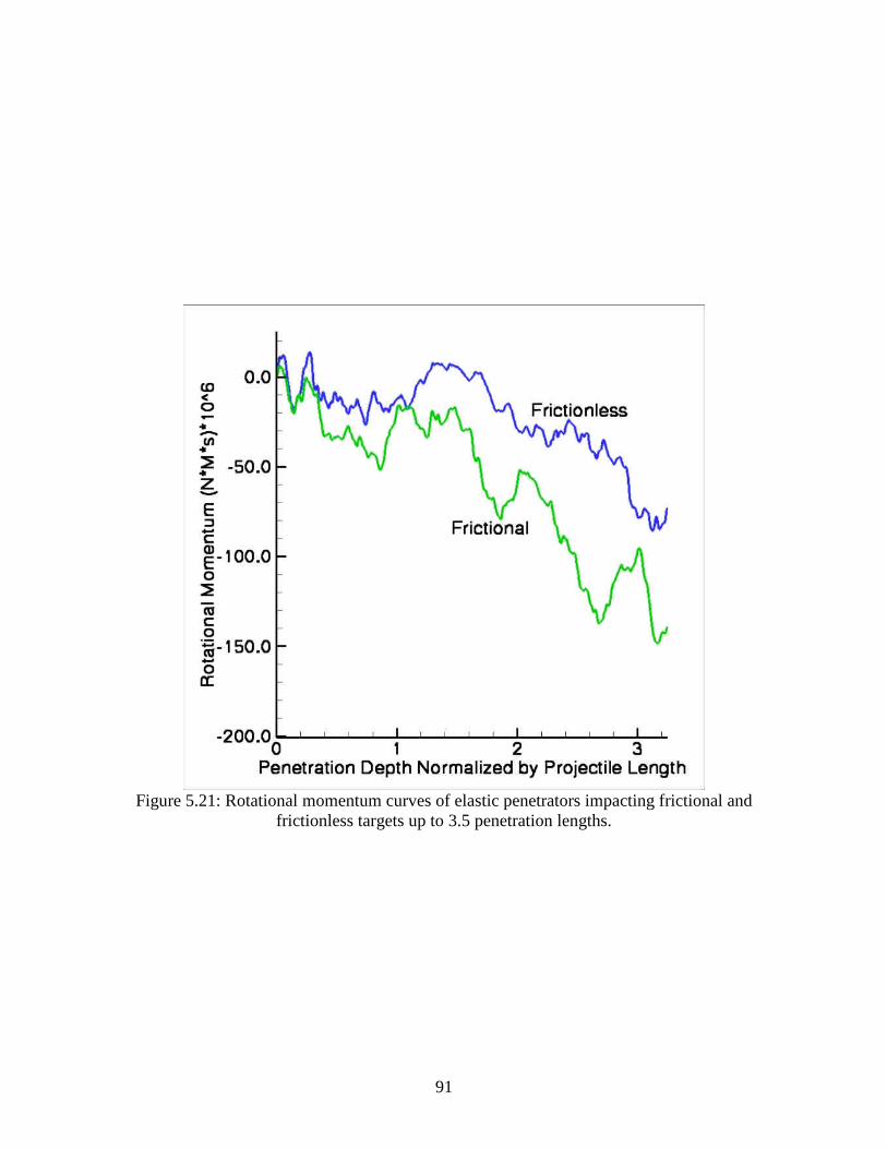
91
Figure 5.21: Rotational momentum curves of elastic penetrators impacting frictional and
frictionless targets up to 3.5 penetration lengths.

92
5.9.1 Projectile Resonance
The physical phenomena that can cause such oscillations are not understood.
However, it is useful to consider a projectile in contact with the sand grains, from the tip
of the projectile to the end of the projectile. If this were the case, these oscillations could
be explained simply. The projectile could begin to rotate and than be restored to its
initial orientation by grains acting on the projectile shaft behind the center of mass. In
this case, this idea is incorrect. Looking at the figures of the penetration event, it can be
seen that the sand grains only contact the nose of the projectile. This being the case an
alternate cause of projectile oscillation must be considered.
A possible solution to this question is that a resonant mode of the penetrator is
becoming activated. To test the feasibility of this idea, resonant frequencies for the
undamped free projectile were calculated by solving the Eigenvalue[16, 65] problem.
[ ] [ ]( )[ ]2 0K M Dω− = (5.1)
[K] and [M] are the finite element stiffness and lumped mass matrices, D is the
displacement matrix for the nodes and ω is the modal frequency in Hz.
This calculation was completed using a program written in Matlab [66] which can
calculate the Eigenvalues and Eigenvectors for a system with a large number of degrees
of freedom. The code was validated by calculating the vibrational frequencies and mode
shapes for a beam and comparing them with their analytic counterparts. This validation
can be found in appendix B, the program itself can be found in appendix C.
The lowest three vibrational frequencies for the projectile were calculated and are
shown in Table 5.2. Also shown in Table 5.2 are the depth of penetrations corresponding

93
to one complete resonant cycle of the modes (assuming a projectile velocity of 1500m/s).
The first three resonant mode shapes are displayed in Figure 5.22 where the first two
modes correspond to projectile bending and the third mode corresponds to projectile
extension and compression. When these modes are compared to the oscillations shown in
the rotational momentum plots, it can be seen that the first mode corresponds to the
oscillations, while the 2nd and 3rd modes are not obviously visible.
Table 5.2: Projectile resonant modes Frequency
MHz Depth of Penetration per cycle
1ω 5.278 .17
2ω 10.785 .084
3ω 11.5 .078
1ω Mass x 2 3.732 .242
1ω Mass x 1/2 7.463 .121

94
Figure 5.22: First three bending shapes arranged from lowest (left) to highest (right)
showing contours of effective stress 3
2 ij ijS S

95
To further probe these oscillations, simulations 25 and 26 were performed. These
simulations have the same target and properties as those in simulation 6 with the variable
of interest being the projectile density. Simulation 25 has a projectile with twice the
density of steel and simulation 26 has a projectile with half the density of steel. This
variable was examined as density affects the vibrational frequencies in beam bending
theories.
In the Euler-Bernoulli beam theory, bending frequencies are given by.
4i i
EIc
ALω
ρ= (5.2)
Where ic is a constant, I is the projectile moment inertia, E is the projectiles modulus
of elasticity, A is the projectiles cross sectional area, and L is the projectile length.
Assuming that the projectile can be modeled with this equation, doubling the density of
the projectile should decrease the modal frequencies by 1/ 2 and halving the projectile
density should increase the modal frequencies by2 . Calculated lowest mode resonant
frequencies from the Eigenvalue analysis compared well to the beam theory.
When the rotational momentum plot shown in Figure 5.23 is examined, a
difference in the oscillation period can be seen. In the interest of comparing these
oscillations with bending theory, a plot of radial momentum is shown in Figure 5.24
where the oscillations are more apparent. The trend of this difference is predicted by
beam bending theory. The denser projectile showed oscillations with a larger period and
the half dense projectile showed oscillations with shorter periods. Approximate periods
were calculated from the points in Figure 5.24 and can be found in Table 5.3.

96
Figure 5.23: Calculated rotational momentum for projectiles with different densities

97
Figure 5.24: Calculated radial momentum for projectiles with different densities
Table 5.3: approximate oscillation periods for various density penetrators Density
3/kg m Scaled Depth of Penetration per Cycle
7823 .2347 15646 .3154 3911.5 .1790

98
It should be noted that the calculated modes correspond to a fully unconstrained
projectile. In the mesoscale simulations the projectile will be constrained by its
interactions with the sand grain; it is not known what effect this may have on the bending
frequencies of the projectile.
These calculations cannot confirm the possibility of the projectile resonating
during penetration. They also say nothing about resonance (if occurring) as a cause of
instability. However, the correspondence of the period of oscillation found in the
projectile rotational momentum plots with the first bending mode does support the idea of
projectile resonance. If projectile resonance is occurring it supports the ideas of Jones et
al.[10] and Graham et al.[17] who predict projectile instability using a simple buckling
analysis.

99
SECTION 6 Summary and Conclusions Summary and Conclusions
During high speed penetration of granular media, projectile motion becomes
unstable due to divergence from initial path or projectile bending. To gain insight into the
causes of projectile instability, a set of 2D mesoscale simulations was conducted
accounting for the physical features in a sand target. In these simulations, the granularity
of the media was incorporated by modeling each discrete particle as they moved and
interacted during the simulations.
The mesoscale simulations were carried out using the 2D Lagrangian finite
element code ISP-TROTP. The discrete sand targets were created using the code ISP-
SAND, developed as part of this work. ISP-SAND can rapidly produce sand targets
containing millions of sand grains with random morphologies.
Using the above capabilities penetration simulations were conducted and the
effect of target parameters on projectile instability was examined. Projectile instability
was quantified using projectile rotational momentum, average lateral forces applied to the
projectile, and final projectile deviation from the expected path. It was demonstrated,
through 2D simulations, that target granularity can produce projectile instability even for
normal impact on the target.
Simulations predicted known phenomena such as stress fingers and highly
compacted target regions under the projectile tip. Simulations considering elastic/plastic
penetrators over-predicted projectile deformation. This may be due to deficiencies in
material models, a lack of penetrator erosion and grain fragmentation, or 2D effects.

100
The heterogeneous response inherent in the mesoscale simulations, results in
unbalanced forces on the impactor causing instability and deviation from the vertical path
that increases with impact velocity. The simulations carried out in this work showed the
following features of penetrator instability:
• Increases with projectile velocity
• Decreases with porosity
• Increases with grain size
• Increases with inter-granular friction coefficient
• Increases with uniform grain size distributions
• Is minimally affected by the random placement of sand grains with similar
distributions
• Is affected by changing the distribution of grains and porosity
In many of the cases, the rotational momentum plots show oscillations with a
similar length scale during penetration at 1500 m/s. These oscillations were found to
correlate with the first unrestrained bending mode of the projectile, and they follow
expected trends predicted by the Euler-Bernoulli beam theory (change depending upon
projectile density). These two results suggest projectile resonance; however, further
work is required to confirm this phenomenon and to determine its effects on instability.
101
BIBLIOGRAPHY
1. Allen, W.A., E.B. Mayfield, and H.L. Morrison, Dynamics of a Projectile Penetrating Sand. J. Appl. Phys., 1957. 28(3): p. 6.
2. Robins, B., New Principals of Gunnery. 1742, London
3. Poncelet, J.V., Cours de Mecanique Industrielle. Vol. first edition. 1829.
4. Poncelet, J.V., Introduction d la Mechanique Industrielle 1839, Bruselles.
5. Davie, N.T., A Method for Describing Nearly Normal Penetration of an OGIVE Nosed Penetrator into Terrestrial Targets. 1979, Sandia Laboratories: Albuquerque NM. p. 60.
6. Feliece, C.W., Personal Communication. 2006: Pullman.
7. Biele, A., An investigation of the terradynamic stability of a scaled-model projectile, in Mechanical Engineering. 1976, Mississippi State University: Starkville.
8. Boulet, R.B. and C.W. Young, Deep Earth Penetration Technology (DEPT). 1999, US Air Force Research Laboratory: Albuquerque.
9. Byers, R.K., P. Yarrington, and A.J. Chabai, Dynamic Penetration of Soil Media by Slender Projectiles. Int. J. Engng. Sci., 1978. 16: p. 11.
10. Jones, S.E., et al., Dynamic Buckling and Instability in Soil and Sand Penetration. PVP, 2004. 489: p. 6.
11. Savvateev, A.F., et al., High-Speed Penetration Into Sand. Int. J. Imp. Engng., 2001. 26: p. 8.
12. Gupta, Y.M., C.W. Feliece, and S.K. Dwivedi, Personal Communication. 2006.
13. Dwivedi, S.K., J.R. Asay, and Y.M. Gupta, Two-dimensional mesoscale simulations of quasielastic reloading and unloading in shock compressed aluminum. J. Appl. Phys., 2006. 100: p. 15.
14. Frew, D.J., M.J. Forrestal, and S.J. Hanchak, Penetration Experiments with Limestone Targets and Ogive-Nose Steel Projectiles J. Appl. Mech., 2000. 67: p. 5.
15. Bathe, K., Finite Element Procedures. 2 ed. 1995: Prentice Hall.
16. Cook, R.D., et al., Concepts and Applications of Finite Element Analysis. 4 ed. 2002: Wiley.

102
17. Graham, C.H., et al., Further Results on the Analysis of Penetrator Stability in Sand and Soil Targets. PVP, 2005: p. 6.
18. Abrahamson, G.R. and J.N. Goodier, Dynamic Flexural Buckling of Rods Within an Axial Plastic Compression Wave. J. Appl. Mech., 1966: p. 7.
19. Gladden, J.R., et al., Dynamic Buckling and Fragmentation in Brittle Rods. PRL 2005. 94: p. 4.
20. Lindberg, H.E., Impact Buckling of a Thin Bar. J. Appl. Mech., 1965: p. 8.
21. Lindberg, H.E. and A.L. Florence, Dynamic Pulse Buckling. 1987: Martinus Nijhoff Publishers.
22. Simonov, I.V. and K.Y. Osipenko, Stability, Paths, and Dynamic Bending of a Blunt Body of Revolution Penetration into an Elastoplastic Medium. J. Appl. Mech. Tech. Phys., 2004. 45(3): p. 11.
23. Bishop, J.E., T.E. Voth, and K.H. Brown, Semi-Infinite Target Penetration by Ogive-Nose Penetrators: Alegra/SHISM Code Predications for Ideal and Non-Ideal Impacts. PVP, 2005: p. 10.
24. Resnyansky, A.D. and N.K. Borune, Shock-wave Compression of a Porous Material. J. Appl. Phys., 2004. 94(4): p. 10.
25. Resnyansky, A.D. and N.K. Bourne, Shock Compression of Dry and Hydrated Sand, in Shock Compression of Condensed Matter. 2003.
26. Tsembelis, K., et al., The Behavior of Sand Under Shock Wave Loading: Experiments and Simulations, in 14 Technical Meeting, DYMAT. 2002: Sevilla, Spain.
27. Vorobiev, O.Y., et al., Simulation of Penetration into Porous Geologic Media. International Journal of Impact Engineering 2007. 34: p. 10.
28. Herrmann, W., Constitutive Equation for the Dynamic Compaction of Ductile Porous Materials. J. Appl. Phys., 1969. 40(6): p. 10.
29. Zukas, J., Introduction to Hydrocodes. 2004: Elsevier Science.
30. Neumann, J.V. and R.D. Richtmyer, A Method for the Numerical Calculation of Hydrodynamic Shocks. J. Appl. Phys, 1950. 21: p. 6.
31. Wilkins, M.L., Calculation of Elastic-Plastic Flow, L.R.L. University of California, Editor. 1963.
32. Wilkins, M.L., Use of Artificial Viscosity in Multidimensional Fluid Dynamic Calculations. J. Comp. Phys., 1980. 36: p. 22.

103
33. Wilkins, M.L. and M.W. Guinan, Impact of Cylinders on a Rigid Boundary. J. Appl. Phys, 1973. 44(3): p. 6.
34. Crowell, G.A., The Descriptive Geometry of Nose Cones. 1996.
35. DiGiulian, T. Calculating CRH. 2004 [cited 2006 7-19-2006]; Available from: http://www.navweaps.com/index_tech/tech-094.htm.
36. Dwivedi, S.K., Material Model for Sand Grains. April 24, 2007, Institute for Shock Physics: Pullman.
37. Khan, A.S. and S. Huang, Continuum Theory of Plasticity. 1995, New York: Wiley-Interscience
38. Malvern, L.E., Introduction to the Mechanics of a Continuous Medium 1969, Englewood Cliffs, New Jersey: Prentice-Hall.
39. Dwivedi, S.K., J.L. Ding, and Y.M. Gupta, Computational Study of Interface Effect on Impact Load Spreading in SiC Multi-Layered Targets. Int. J. Comp. Meth, 2005. 2(3): p. 32.
40. Gupta, Y.M., Physics 592, Wave Propagation Seminar 2006.
41. Johnson, J.N., Single-Particle Model of a Solid: The Mie-Gruneisen Equation Am. J. Phys 1968. 36: p. 3.
42. Seaman, L. and D.R. Curran, TROTT Computer Program for Two-Dimensional Stress Wave Propagation. 1978, SRI International: Menlo Park, CA.
43. Winey, J.M., R. Feng, and Y.M. Gupta, Isotropic Material Models for the Elastic Response of Sapphire and Quartz Single Crystals Under Shock Wave Loading. 2001, Institute for Shock Physics. p. 14.
44. Feng, R., G.F. Raiser, and Y.M. Gupta, Shock Response of Polycrystalline Silicon Carbide Undergoing Inelastic Deformation. J. Appl. Phys, 1996. 79(3): p. 10.
45. Simha, C.H.M. and Y.M. Gupta, Time-Dependent Inelastic Deformation of Shocked Soda-Lime Glass. J. Appl. Phys, 2004. 96(4): p. 10.
46. Frondel, C., Dana's System of Mineralogy, Vol. III - Silica Materials 1962, New York: John Wiley & Sons.
47. Swegle, J.W., Irreversible Phase Transitions and Wave Propagation in Silicate Geologic Materials. J. Appl. Phys, 1990. 64(4): p. 17.
48. Ward, R.W., in 14th Piezoelectric Devices Conference and Exhibition. 1992.
49. Krinsley, D.H. and J.C. Doornkamp, Atlas of Quartz Sand Surface Textures. 1973: Cambridge University Press.

104
50. Mahaney, W.C., Atlas of Sand Grain Surface Textures and Applications. 2002, New York Oxford University Press.
51. Dwivedi, S.K., Personal Communication, R.D. Teeter, Editor. 2005: Pullman.
52. Teeter, R.D., Voronoi Tessellation with Varying Grain Sizes and Voids. 2004, ISP: Pullman.
53. Teeter, R.D. and K. Perkins, ISP-VORN. 2005: Pullman.
54. Okabe, A., Spatial Tessellations: Concepts and Applications of Voronoi Diagrams. 2000, Chichester; New York: Wiley.
55. Kreyszig, E., Advanced Engineering Mathematics. 8 ed. 1999: John Wiley & Sons.
56. ASTM, Manual on Test Sieving Methods. Guidelines for Establishing Sieve Analysis Procedures, ed. C. E-29. 1972, Philadelphia, Pa: ASTM.
57. Allen, W.A., E.B. Mayfield, and H.L. Morrison, Dynamics of a Projectile Penetrating Sand. Part 2. J. Appl. Phys, 1957. 28(11): p. 5.
58. Forrestal, M.J., L.M. Lee, and B.D. Jenrette, Laboritory-Scale Penetration Experiments into Geological Targets to Impact Velocities of 2.1 km/s. J. Appl. Mech., 1986. 53: p. 4.
59. Bardenhagen, S.G. and J.U. Brackbill, Dynamic Stress Bridging in Granular Material. J. Appl. Phys, 1998. 83(11): p. 9.
60. Geng, J., et al., Memory in Two-Dimensional Heap Experiments. Phys. Rev. E, 2001. 64: p. 4.
61. Grantham, S.G., W.G. Proud, and J.E. Field. The Study of Internal Deformation Fields in Materials Using Digital Speckle Radiography. in 25th International Congress on High-Speed Photography and Photonics. 2003: SPIE.
62. Bowden, F.P. and E.H. Freitag, The Friction of Solids at Very High Speeds I. Metal on Metal; II. Metal on Diamond. Proceedings of the Royal Society of London. Series A, Mathamatical and Physical Sciences, 1958. A: p. 17.
63. Bowden, F.P. and P.A. Persson, Deformation, Heating and Melting of Solids in High-Speed Friction. Proceedings of the Royal Society of London. Series A, Mathamatical and Physical Sciences, 1961. 260(A): p. 25.
64. Jones, S.E., et al., A One-Dimensional Analysis of Rigid-Body Penetration With High-Speed Friction. Proceeding of the Institution of Mechanical Engineers, 2003. 217(C): p. 11.

105
65. Sehmi, N.S., Large Order Structural Eigenanalysis Techniques Algorithms for Finitie Element Systems. 1989: Ellis Horwood Limited.
66. MathWorks, Matlab 7.1. 2007.
67. Bottega, W.J., Engineering Vibrations. 1 ed. 2006: Taylor & Francis.

106
Appendix A: Finite Element Mesh Size Selection
To probe the effects of mesh size on the simulation results, two simulations were
run keeping all things constant varying only the mesh size in the penetrator. The
simulations were run using the materials properties given in Table 3.1 and Table 3.2. The
constant simulation parameters included an inelastic penetrator entering inelastic 60um
grains at 1000 m/s. Mesh sizes used in the penetrators were 10 and 5µm.
Upon analyzing the results of the simulations it was found that there was some
difference in the final result. This is as expected. These simulations are considering
chaotic grain interactions and because of this, small changes in grain morphology or
mesh size can have a large effect on the final result. As this is expected, in this work an
emphasis has been put on the trends seen in the results rather than phenomenon seen in
each individual result.
Figure A.1 and A.2 show the results for the 10 and 5 µm mesh sizes at
approximately .4 depths of penetration. This time was chosen as contact problems arose
in the 5 µm mesh sized projectile after this time. It can be seen that the deformation
fields have some differences and that the projectile with the fine mesh is showing strange
deformations at the tip where single elements have become highly deformed and protrude
from the penetrator. Figure A.3 shows rotational momentum plots from the two cases. It
can be seen that the trends are reasonably similar up to the termination point for the 5 µm
mesh simulations. However, trends may continually grow apart at further times.
Small perturbations added to the initial simulations can cause differences in the
final simulation results. Also these perturbations can be added from various factors such

107
as grain morphology, mesh size, mesh structure, initial penetrator position, as well as
others. To eliminate mesh size as a variable a single mesh size was used. Due to the
unrealistic deformation features (mesh folding) found in the 5 µm mesh size penetrator a
mesh size of 10 µm was used through out the simulations.

108
Figure A.1: Snapshot at .65 us showing the deformation field in the 10µm mesh size penetrator and grains.

109
Figure A.2: Snapshot at .65 us showing the deformation field in the 5µm mesh size penetrator and grains.
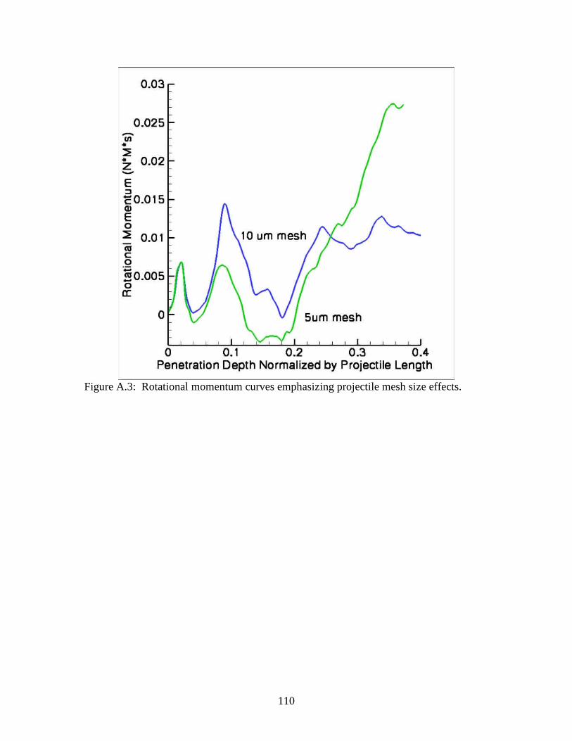
110
Figure A.3: Rotational momentum curves emphasizing projectile mesh size effects.

111
Appendix B: Vibration Mode Code Validation
The Finite Element Program (FE) used to calculate the projectile vibrational
modes was written using Matlab and can be found in appendix 3. To verify that no
programming mistakes were made and that the method is sound, the code was used to
calculate the first three bending modes for the problem of a cantilever beam.
The beam was fixed at it left side and had dimensions of .1 m high, 1 m deep, and
5 m long. The slenderness ratio of the beam was 50 making Euler-Bernoulli beam theory
applicable. Using beam theory Bottega [67] analytically calculated the first three
bending modes for this problem, results can be found in Table B.1 in the analytic row.
The first three bending modes of the beam were calculated using three different
mesh sizes of 50, 25, and 10 mm. Results for these calculations can again be found in
Table B.1 and compared against the theoretical values. As the mesh is refined the FE
calculations converge to the theoretical value and have a relative error of less than 1.008
for the lowest mode. The first three calculated mode shapes can be seen in Figure B.1
and conform to theory.
Table B.1: Bending modes for a cantilever beam Solution
1ω Hz Error 1ω 2ω Hz Error 2ω 3ω Hz Error 3ω
Analytic 20.57 - 128.9 - 361.0 - 50 mm mesh 25.468 1.238 159.3 1.235 440.6 1.231 25 mm mesh 21.665 1.053 135.4 1.050 378.35 1.048 10 mm mesh 20.727 1.008 129.7 1.006 362.26 1.004

112
Figure B.1 First three calculated bending modes showing contours of effective stress (arbitrary units)

113
Appendix C: Matlab Bending Mode Program %Eigen Solver for to find structural bending modes using constant strain triangle finite elements clc clear format long fid=fopen('ogive.mesh', 'r');%Read in the mesh val=fscanf(fid, '%d %d', 2) pts=fscanf(fid, '%e %e', [2,val(1)]); con=fscanf(fid, '%d %d', [3,val(2)]); pts=pts'; pts=pts/1000.0;%convert to meters con=con'; cnta=0 fclose(fid); %produce materail properties matrix Kmod=163.9e9;%Pa Gmod=77.5e9;%Pa ro=7823.0*2 Emod=9*Kmod/(1+3*Kmod/Gmod); poi=(1-2*Gmod/(3*Kmod))/(2+(2*Gmod)/(3*Kmod)); %poi=0.0 E=[1.0-poi,poi,0;poi,1.0-poi,0;0,0,(1.0-2.0*poi)/2.0]*Emod/((1.0+poi)*(1.0-2.0*poi)); K(1:val(1)*2,1:val(1)*2)=0.0; mass(1:val(1)*2,1:val(1)*2)=0.0; Atot=0.0; for i=1:val(2); %Formulate B matrix for CST B(1,1)=pts(con(i,2),2)-pts(con(i,3),2); B(1,2)=0.0; B(1,3)=pts(con(i,3),2)-pts(con(i,1),2); B(1,4)=0.0; B(1,5)=pts(con(i,1),2)-pts(con(i,2),2); B(1,6)=0.0; B(2,1)=0.0; B(2,2)=pts(con(i,3),1)-pts(con(i,2),1); B(2,3)=0.0; B(2,4)=pts(con(i,1),1)-pts(con(i,3),1); B(2,5)=0.0; B(2,6)=pts(con(i,2),1)-pts(con(i,1),1); B(3,1)=pts(con(i,3),1)-pts(con(i,2),1); B(3,2)=pts(con(i,2),2)-pts(con(i,3),2); B(3,3)=pts(con(i,1),1)-pts(con(i,3),1); B(3,4)=pts(con(i,3),2)-pts(con(i,1),2); B(3,5)=pts(con(i,2),1)-pts(con(i,1),1); B(3,6)=pts(con(i,1),2)-pts(con(i,2),2); %Calculate Area of the CST A=.5*det([pts(con(i,1),1),pts(con(i,1),2),1.0;pts(c on(i,2),1),pts(con(i,2),2),1.0;pts(con(i,3),1),pts(con(i,3),2),1.0]); B=B/(2.0*A); Atot=Atot+A; %Produce the Mass Matrix

114
mass(con(i,1)*2-1,con(i,1)*2-1)=mass(con(i,1)*2-1,c on(i,1)*2-1)+ro*A*1.0/3.0; mass(con(i,1)*2,con(i,1)*2)=mass(con(i,1)*2,con(i,1 )*2)+ro*A*1.0/3.0; mass(con(i,2)*2-1,con(i,2)*2-1)=mass(con(i,2)*2-1,c on(i,2)*2-1)+ro*A*1.0/3.0; mass(con(i,2)*2,con(i,2)*2)=mass(con(i,2)*2,con(i,2 )*2)+ro*A*1.0/3.0; mass(con(i,3)*2-1,con(i,3)*2-1)=mass(con(i,3)*2-1,c on(i,3)*2-1)+ro*A*1.0/3.0; mass(con(i,3)*2,con(i,3)*2)=mass(con(i,3)*2,con(i,3 )*2)+ro*A*1.0/3.0; Kelem=A*transpose(B)*E*B;%K for the element %build K with Kelem for j=1:3 for m=1:3 K(con(i,j)*2-1,con(i,m)*2-1)=K(con(i,j)*2-1 ,con(i,m)*2-1)+Kelem(j*2-1,m*2-1); K(con(i,j)*2,con(i,m)*2-1)=K(con(i,j)*2,con (i,m)*2-1)+Kelem(j*2,m*2-1); K(con(i,j)*2-1,con(i,m)*2)=K(con(i,j)*2-1,con(i,m)*2)+Kelem(j*2-1,m*2); K(con(i,j)*2,con(i,m)*2)=K(con(i,j)*2,con(i,m)*2)+K elem(j*2,m*2); end end end solve=2 if(solve==1)%Solve for with constraints (used to co nstrain the beam problem) %find u constraints ucon(1:val(1)*2)=0; u(1:val(1)*2)=0.0; for i=1:val(1); if(pts(i,1)<-10.00001)%impose displacement constraints u(i*2)=0.0; u(i*2-1)=0.0; ucon(i*2)=1; ucon(i*2-1)=1; cnta=cnta+2; end end %find F constraints Fcon(1:val(1)*2)=0; F(1:val(1)*2)=0.0; load=1000000.0; nds=0 for i=1:val(1); if(pts(i,1)>100.9999)%find nodes that will have applied loads nds=nds+1 end end for i=1:val(1); if(pts(i,1)>100.9999)%Apply loads to the me sh F(i*2)=load/nds; %load=load+F(i*2-1) Fcon(i*2)=1; end end

115
%find constrained stiffness matrix KF(1:val(1)*2-cnta,1:val(1)*2-cnta)=0.0; massF(1:val(1)*2-cnta,1:val(1)*2-cnta)=0.0; Fsrt(1:val(1)*2-cnta,1)=0.0; cnta=0; cntb=0; for i=1:val(1)*2 i/(val(1)*2) if(ucon(i)==1); cnta=cnta+1; continue end cntb=0; Fsrt(i-cnta,1)=F(i); for j=1:val(1)*2 if(ucon(j)==1); cntb=cntb+1; continue end KF(i-cnta,j-cntb)=K(i,j); massF(i-cnta,j-cntb)=mass(i,j); end end %UFin=inv(KF)*Fsrt; cnta=0; %for i=1:val(1)*2 % if(ucon(i)==1); % cnta=cnta+1; % continue % end %u(i)=UFin(i-cnta); %end dpts(val(1),2)=0; cnta=0.0 % for i=1:val(1); % if(ucon(i)==1); % cnta=cnta+1; % continue % end %dpts(i,1)=pts(i,1)+u(i*2-1); %dpts(i,2)=pts(i,2)+u(i*2); % end %for i=1:val(1)*2 % if(Fcon(i)==1) % u(i); % end % end [V,D] = eigs(KF,massF,50,'sm'); end if(solve==2)%unconstrained body %KF=K;

116
%massF=mass; cntb=0; cnta=0; ucon(1:val(1)*2)=0; u(1:val(1)*2)=0.0; opts.tol=1e-50; [V,D] = eigs(K,mass,50,'sm',opts); end clear K mass KF massF for i=1:6%val(1)*2-cnta if(D(i,i)<inf) i sqrt(D(i,i)) end end %calculate theoretical W's for a cantilever beam w1=3.516*(Emod*(.1^3/12)/(.1*ro*5^4))^.5 w2=22.03*(Emod*(.1^3/12)/(.1*ro*5^4))^.5 w3=61.70*(Emod*(.1^3/12)/(.1*ro*5^4))^.5 %Calculate Error between calculated and theoretical W e1=sqrt(D(1,1))/w1 e1=sqrt(D(2,2))/w2 e1=sqrt(D(3,3))/w3

117
Visualization program used to plot mode shapes
%This M-file is used to plot the results of the pre viously performed eiganvalue analysis mode=6 cont=4; %1 strain x, 2 strain y, 3 strain xy , 4 se f cnta=0; ncnt(1:val(1))=0; nstrn(1:val(1),1:4)=0.0; %V(:,mode)/1000.0 Estrn(val(2),1:3)=0.0; for i=1:val(1); if(ucon(i*2)==1) Ufin(i,1)=0.0; Ufin(i,2)=0.0; dpts(i,1)=pts(i,1); dpts(i,2)=pts(i,2); cnta=cnta+1; continue end Ufin(i,1)=V((i-cnta)*2-1,mode); Ufin(i,2)=V((i-cnta)*2,mode); dpts(i,1)=pts(i,1)+V((i-cnta)*2-1,mode)/1000000 .00; dpts(i,2)=pts(i,2)+V((i-cnta)*2,mode)/1000000.0 0; end for i=1:val(2); %Find local dispacment Uloc(1,1)=Ufin(con(i,1),1); Uloc(2,1)=Ufin(con(i,1),2); Uloc(3,1)=Ufin(con(i,2),1); Uloc(4,1)=Ufin(con(i,2),2); Uloc(5,1)=Ufin(con(i,3),1); Uloc(6,1)=Ufin(con(i,3),2); %Formulate B matrix for CST B(1,1)=pts(con(i,2),2)-pts(con(i,3),2); B(1,2)=0.0; B(1,3)=pts(con(i,3),2)-pts(con(i,1),2); B(1,4)=0.0; B(1,5)=pts(con(i,1),2)-pts(con(i,2),2); B(1,6)=0.0; B(2,1)=0.0; B(2,2)=pts(con(i,3),1)-pts(con(i,2),1); B(2,3)=0.0; B(2,4)=pts(con(i,1),1)-pts(con(i,3),1); B(2,5)=0.0; B(2,6)=pts(con(i,2),1)-pts(con(i,1),1); B(3,1)=pts(con(i,3),1)-pts(con(i,2),1); B(3,2)=pts(con(i,2),2)-pts(con(i,3),2); B(3,3)=pts(con(i,1),1)-pts(con(i,3),1); B(3,4)=pts(con(i,3),2)-pts(con(i,1),2); B(3,5)=pts(con(i,2),1)-pts(con(i,1),1); B(3,6)=pts(con(i,1),2)-pts(con(i,2),2);

118
A=.5*det([pts(con(i,1),1),pts(con(i,1),2),1.0;pts(c on(i,2),1),pts(con(i,2),2),1.0;pts(con(i,3),1),pts(con(i,3),2),1.0]); B=B/(2.0*A); %Compute Element Strains Estrn(i,1:3)=B*Uloc; for j=1:3 nstrn(con(i,j),1)=nstrn(con(i,j),1)+Estrn(i,1); nstrn(con(i,j),2)=nstrn(con(i,j),2)+Estrn(i,2); nstrn(con(i,j),3)=nstrn(con(i,j),3)+Estrn(i,3); end ncnt(con(i,1))=ncnt(con(i,1))+1; ncnt(con(i,2))=ncnt(con(i,2))+1; ncnt(con(i,3))=ncnt(con(i,3))+1; end for i=1:val(2) sigz=(Estrn(i,1)-Estrn(i,2))*poi*Emod/((1.0+poi )*(1.0-2.0*poi)); strn(1,1)=Estrn(i,1); strn(2,1)=Estrn(i,2); strn(3,1)=Estrn(i,3); Estress=E*strn; Estrn(i,4)=1/sqrt(2)*((Estress(1)-Estress(2))^2 +(Estress(2)-sigz)^2+(sigz-Estress(1))^2+6*(Estress(3)^2))^.5; end for i=1:val(1); for j=1:3; nstrn(i,j)=nstrn(i,j)/ncnt(i); end sigz=(nstrn(i,1)-nstrn(i,2))*poi*Emod/((1.0+poi )*(1.0-2.0*poi)); strn(1,1)=nstrn(i,1); strn(2,1)=nstrn(i,2); strn(3,1)=nstrn(i,3); stress=E*strn; nstrn(i,4)=1/sqrt(2)*((stress(1)-stress(2))^2+( stress(2)-sigz)^2+(sigz-stress(1))^2+6*(stress(3)^2))^.5; end trisurf(con,dpts(:,1),dpts(:,2),[],Estrn(:,cont),'L ineStyle', 'none') view(0,90) daspect([1 1 1])