Embed Size (px)
Citation preview

BUREAU OF DESIGN AND ENVIRONMENT MANUAL
Chapter Forty-seven
RURAL TWO-LANE/MULTILANE STATE HIGHWAYS
(New Construction/Reconstruction)

Illinois RURAL TWO-LANE/MULTILANE STATE HIGHWAYS September 2010
HARD COPIES UNCONTROLLED

Illinois RURAL TWO-LANE/MULTILANE STATE HIGHWAYS September 2010
47-i HARD COPIES UNCONTROLLED
Chapter Forty-seven RURAL TWO-LANE/MULTILANE STATE HIGHWAYS
(New Construction/Reconstruction)
Table of Contents
Section Page 47-1 GENERAL ............................................................................................................... 47-1.1 47-2 TWO-LANE HIGHWAYS ......................................................................................... 47-2.1
47-2.01 General .................................................................................................. 47-2.1 47-2.02 Typical Sections .................................................................................... 47-2.1 47-2.03 Passing Sight Distance .......................................................................... 47-2.1
47-2.03(a) Design Derivation ........................................................... 47-2.1 47-2.03(b) Applications .................................................................... 47-2.7
47-2.04 Passing Lanes ....................................................................................... 47-2.7
47-2.04(a) General .......................................................................... 47-2.7 47-2.04(b) Warrants ........................................................................ 47-2.8 47-2.04(c) Design ............................................................................ 47-2.8
47-2.05 Two-Way, Left-Turn Lanes (TWLTL) ..................................................... 47-2.12 47-2.06 Tables of Design Criteria ....................................................................... 47-2.12
47-3 MULTILANE HIGHWAYS ....................................................................................... 47-3.1
47-3.01 General .................................................................................................. 47-3.1 47-3.02 Design Speed ........................................................................................ 47-3.1 47-3.03 Typical Sections .................................................................................... 47-3.1 47-3.04 Tables of Design Criteria ....................................................................... 47-3.2
47-4 REFERENCES ........................................................................................................ 47-4.1
Illinois RURAL TWO-LANE/MULTILANE STATE HIGHWAYS September 2010
47-ii HARD COPIES UNCONTROLLED

Illinois RURAL TWO-LANE/MULTILANE STATE HIGHWAYS September 2010
47-1.1 HARD COPIES UNCONTROLLED
Chapter Forty-seven RURAL TWO-LANE/MULTILANE
STATE HIGHWAYS (New Construction/Reconstruction)
Chapter 47 provides guidance in the design of rural two-lane principal arterials, multilane minor arterials, two-lane minor arterials, and collectors on the State highway system. Information that is also applicable to these facilities is included in the following chapters:
Chapter 11 discusses the procedures for determining the facility location.
Chapter 14 discusses intersection design studies.
Chapters 31, 32, 33, 34, and 39 provide guidance on geometric design elements that are also applicable to these facilities.
Chapter 35 provides guidelines for access control along interchange crossroads and intersections. It also discusses the procedures for preparing access control plans.
Chapter 36 provides information on the design of intersections including left- and right-turn lanes, channelization, and intersection sight distance.
Chapter 38 provides guidelines on roadside safety issues.
Chapter 45 discusses the procedures for designing expressways.
47-1 GENERAL
Construction of new two-lane State highways, full reconstruction of long segments of existing two-lane State highways, or new construction of rural multilane State highways without access control are no longer common highway designs in Illinois. Instead, existing two-lane highways are more commonly improved using 3R guidelines (Chapter 49) or upgraded to a four-lane expressway design with partial access control (Chapter 45).

Illinois RURAL TWO-LANE/MULTILANE STATE HIGHWAYS September 2010
47-1.2 HARD COPIES UNCONTROLLED

Illinois RURAL TWO-LANE/MULTILANE STATE HIGHWAYS October 2015
47-2.1 HARD COPIES UNCONTROLLED
47-2 TWO-LANE HIGHWAYS
47-2.01 General
The minimum design for a State route is a two-lane, two-way highway. In some areas of the State, the two-lane highway system carries a large portion of the rural traffic. Many of these highways are located near major urbanized areas and are experiencing rapid growth in traffic.
The following describes some of the more common situations where new construction or reconstruction projects might be proposed for a two-lane highway improvement:
realigning of an existing low-speed horizontal curve;
raising the profile gradeline of a roadway to remedy flooding problems;
providing a bypass around a small community;
modifying the vertical profile or improving an intersection to enhance safety;
upgrading a major route (i.e., arterial or collector) approaching an urbanized area where the current ADT is 5000 or greater, and where there is a small probability of traffic growth warranting four lanes in 20 years; and/or
increasing passing opportunities to break up platoons and to reduce delay.
47-2.02 Typical Sections
Figures 47-2.A and 47-2.B illustrate typical schematic cross sections for two-lane highways. The tables in Section 47-2.06 provide the minimum criteria for lane widths, shoulder widths, and other cross section elements that should be used on rural two-lane highways.
47-2.03 Passing Sight Distance
47-2.03(a) Design Derivation
Passing sight distance considerations are limited to two-lane, two-way highways. On these facilities, vehicles may overtake slower moving vehicles, and the passing maneuver must be accomplished on a lane used by opposing traffic.
The minimum passing sight distance for two-lane highways is determined from the sum of four distances as illustrated in Figure 47-2.C. Figure 47-2.D and the following provides the basic assumptions used to develop passing sight distance values for design:

Illinois RURAL TWO-LANE/MULTILANE STATE HIGHWAYS October 2015
47-2.2 HARD COPIES UNCONTROLLED
TYPI
CA
L TA
NG
ENT
SEC
TIO
N F
OR
RU
RA
L TW
O-L
AN
E H
IGH
WA
YS
Figu
re 4
7-2.
A

Illinois RURAL TWO-LANE/MULTILANE STATE HIGHWAYS October 2015
47-2.3 HARD COPIES UNCONTROLLED
TYPI
CA
L SE
CTI
ON
FO
R S
UPE
REL
EVA
TED
RU
RA
L TW
O-L
AN
E H
IGH
WA
YS
Figu
re 4
7-2.
B

Illinois RURAL TWO-LANE/MULTILANE STATE HIGHWAYS October 2015
47-2.4 HARD COPIES UNCONTROLLED
Note: The Illinois MUTCD definition for passing sight distance uses only the second phase of
signing and pavement markings distances.
ELEMENTS OF PASSING DISTANCE (Two-Lane Highways)
Figure 47-2.C

Illinois RURAL TWO-LANE/MULTILANE STATE HIGHWAYS October 2015
47-2.5 HARD COPIES UNCONTROLLED
Not
e:
See
Fig
ure
33-4
.D fo
r K-v
alue
s fo
r pas
sing
sig
ht d
ista
nces
for p
asse
nger
car
s on
cre
st v
ertic
al c
urve
s.
MIN
IMU
M D
ESIG
N P
ASS
ING
SIG
HT
DIS
TAN
CE
(Ass
umes
Ent
ire M
aneu
ver i
s C
ompl
eted
)
Figu
re 4
7-2.
D

Illinois RURAL TWO-LANE/MULTILANE STATE HIGHWAYS October 2015
47-2.6 HARD COPIES UNCONTROLLED
1. Initial Maneuver Distance (d1). This is the distance traversed during the perception and reaction time and during the initial acceleration to the point of encroachment on the left lane. For the initial maneuver, the overtaken vehicle is assumed to be traveling at a uniform speed, and the passing vehicle is accelerating at a rate from 1.41 mph/sec to 1.47 mph/sec (2.25 km/h/sec to 2.37 km/h/sec). The average speed of the passing vehicle is assumed to be 10 mph (15 km/h) greater than the overtaken vehicle. Use Equation 47-2.1 to determine d1:
2at
mvt47.1d 111 (US Customary) Equation 47-2.1
2at
mv6.3
td 11
1 (Metric) Equation 47-2.1
where: t1 = time of initial maneuver, sec a = average acceleration, mph/sec (km/h/sec) v = average speed of passing vehicle, mph (km/h) m = difference in speed of passed vehicle and passing vehicle, mph (km/h)
2. Distance of Passing Vehicle in Left Lane (d2). This is the distance traveled by the passing vehicle while it occupies the left lane. Use Equation 47-2.2 to determine d2:
22 vt47.1d (US Customary) Equation 47-2.2
6.3
vtd 2
2 (Metric) Equation 47-2.2
where: t2 = time passing vehicle occupies the left lane, sec v = average speed of passing vehicle, mph (km/h) 3. Clearance Distance (d3). This is the distance between the passing vehicle at the end of
its maneuver and the opposing vehicle. Based on various studies, this clearance distance at the end of the passing maneuver is assumed to be between 100 ft and 250 ft (30 m and 75 m).
4. Opposing Vehicle Distance (d4). This is the distance traversed by an opposing vehicle during the time the passing vehicle occupies the left lane. As shown in Figure 47-2.C, the opposing vehicle appears after approximately one-third of the passing maneuver (d2) has been accomplished. The opposing vehicle is assumed to be traveling at the same speed as the passing vehicle. Therefore, d4 = 0.67 d2.
Illinois RURAL TWO-LANE/MULTILANE STATE HIGHWAYS October 2015
47-2.7HARD COPIES UNCONTROLLED
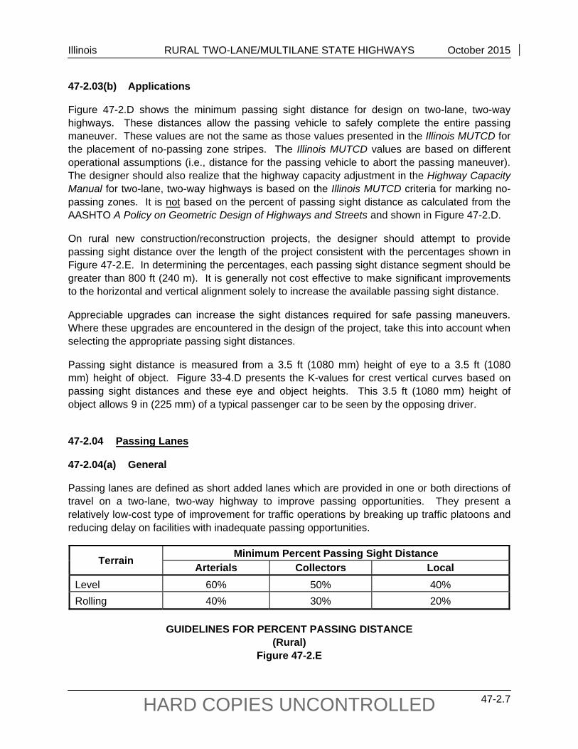
47-2.03(b) Applications
Figure 47-2.D shows the minimum passing sight distance for design on two-lane, two-way highways. These distances allow the passing vehicle to safely complete the entire passing maneuver. These values are not the same as those values presented in the Illinois MUTCD for the placement of no-passing zone stripes. The Illinois MUTCD values are based on different operational assumptions (i.e., distance for the passing vehicle to abort the passing maneuver). The designer should also realize that the highway capacity adjustment in the Highway Capacity Manual for two-lane, two-way highways is based on the Illinois MUTCD criteria for marking no-passing zones. It is not based on the percent of passing sight distance as calculated from the AASHTO A Policy on Geometric Design of Highways and Streets and shown in Figure 47-2.D.
On rural new construction/reconstruction projects, the designer should attempt to provide passing sight distance over the length of the project consistent with the percentages shown in Figure 47-2.E. In determining the percentages, each passing sight distance segment should be greater than 800 ft (240 m). It is generally not cost effective to make significant improvements to the horizontal and vertical alignment solely to increase the available passing sight distance.
Appreciable upgrades can increase the sight distances required for safe passing maneuvers. Where these upgrades are encountered in the design of the project, take this into account when selecting the appropriate passing sight distances.
Passing sight distance is measured from a 3.5 ft (1080 mm) height of eye to a 3.5 ft (1080 mm) height of object. Figure 33-4.D presents the K-values for crest vertical curves based on passing sight distances and these eye and object heights. This 3.5 ft (1080 mm) height of object allows 9 in (225 mm) of a typical passenger car to be seen by the opposing driver.
47-2.04 Passing Lanes
47-2.04(a) General
Passing lanes are defined as short added lanes which are provided in one or both directions of travel on a two-lane, two-way highway to improve passing opportunities. They present a relatively low-cost type of improvement for traffic operations by breaking up traffic platoons and reducing delay on facilities with inadequate passing opportunities.
Terrain Minimum Percent Passing Sight Distance Arterials Collectors Local
Level 60% 50% 40%Rolling 40% 30% 20%
GUIDELINES FOR PERCENT PASSING DISTANCE (Rural)
Figure 47-2.E

Illinois RURAL TWO-LANE/MULTILANE STATE HIGHWAYS October 2015
47-2.8 HARD COPIES UNCONTROLLED
Truck-climbing lanes are one type of passing lane used on steep grades to provide passenger cars with an opportunity to pass slow-moving vehicles. The warrant and design criteria for truck-climbing lanes are discussed in Chapter 33. Procedures for developing the climbing lane capacity analysis are also shown in Chapter 33.
Passing lanes may serve to improve safety on a segment of two-lane highway. Three-lane roadways may be considered an intermediate solution to the ultimate expansion to a four-lane highway. The various methods of providing the third lane are shown in Figure 47-2.F.
47-2.04(b) Warrants
Passing lanes other than truck-climbing lanes may be warranted on two-lane facilities where passing opportunities are not adequate. Passing lanes also may be warranted, based on an engineering study that includes judgment, operational experience, and a capacity analysis. The use of a passing lane will be determined on a case-by-case basis. For more information on passing lane warrants, see the FHWA publication Low Cost Methods for Improving Traffic Operations on Two-Lane Roads, Report No. FHWA-IP-87-2.
47-2.04(c) Design
1. Capacity Analysis. Low Cost Methods for Improving Traffic Operations on Two-Lane Roads presents approximate adjustments that can be made to the capacity methodology in the Highway Capacity Manual. These adjustments can be used to estimate the level-of-service benefits from adding passing lanes to two-lane facilities.
2. Spacing. When passing lanes are provided to improve the overall traffic operations over a length of roadway, they should be constructed systematically at regular intervals. Typical spacing for passing lanes may range from 3 miles to 10 miles (5 km to 15 km). Actual spacing of passing lanes will depend on the traffic volumes, right-of-way availability, and existing passing opportunities.
3. Location. When determining where to locate passing lanes, the designer should consider the following factors:
a. Costs. Locate passing lanes to minimize costs. Rough terrain will generally increase the costs for construction of passing lanes.
b. Appearance. The passing lane location should appear logical to the driver. The value of passing lanes is more obvious to the driver at locations where passing sight distances are restricted or where opposing volumes are significant.
c. Horizontal Alignment. Avoid locating passing lanes on highway sections with low-speed horizontal curves.

Illinois RURAL TWO-LANE/MULTILANE STATE HIGHWAYS October 2015
47-2.9 HARD COPIES UNCONTROLLED
TYPICAL CONFIGURATIONS FOR PASSING LANES
Figure 47-2.F

Illinois RURAL TWO-LANE/MULTILANE STATE HIGHWAYS October 2015
47-2.10 HARD COPIES UNCONTROLLED
d. Vertical Alignment. Where practical, construct passing lanes on a sustained upgrade. The upgrade will generally cause a greater speed differential between slow moving vehicles and passing vehicles. However, passing lanes in level terrain still should be considered where the demand for passing opportunities exceeds supply.
e. Sight Distance. Locate the passing lane where there will be adequate sight distance to both the entrance and exit tapers of the additional lane. Because of sight distance concerns, do not locate exit tapers just beyond a crest vertical curve.
f. Intersections. Use special care when designing passing lanes through intersections and high-volume commercial entrances.
g. Structures. Avoid placing passing lanes where structures (e.g., large culverts, bridges) will restrict the overall width of the traveled way, passing lane, and shoulders.
h. Alternative Configurations. See Figure 47-2.F for various configurations of passing lanes.
4. Widths. Passing lane widths should be the same width as the adjacent travel lane width. Paved shoulder widths next to the passing lane should be a minimum of 4 ft (1.2 m).
5. Tapers. Design passing lanes by providing an additional lane to the right side of the traveled way; see Figure 47-2.G. Develop the additional lane with an entrance taper of 25:1. For the exit taper, the most commonly used taper rate is 50:1. However, where a location warrants an extended length of taper, the following equation may be used:
L = WS (US Customary) Equation 47-2.3 L = 0.6WS (Metric) Equation 47-2.3 where: L = length of taper, ft (m) W = width of passing lane, ft (m) S = design speed, mph (km/h)
6. Length. The length of the passing lane will be determined by traffic volumes, length of the platoon, location of major intersections, geometrics, and distances between successive passing opportunities. The optimal length of passing lanes is usually between ½ mile and 1 mile (1 km and 1.5 km). At a minimum, passing lanes should not be less than 1000 ft (300 m) long. On the other hand, passing lane lengths greater than 1 mile (1.5 km) tend to have diminishing reductions in platooning per unit length.

Illinois RURAL TWO-LANE/MULTILANE STATE HIGHWAYS October 2015
47-2.11 HARD COPIES UNCONTROLLED
TYPI
CA
L D
ESIG
N L
AYO
UT
FOR
ON
E D
IREC
TIO
N P
ASS
ING
LA
NE
Figu
re 4
7-2.
G
Not
e:
For f
inal
sig
ning
and
pav
emen
t mar
king
s, c
onta
ct th
e B
urea
u of
Ope
ratio
ns.

Illinois RURAL TWO-LANE/MULTILANE STATE HIGHWAYS October 2015
47-2.12 HARD COPIES UNCONTROLLED
7. Typical Design Layout. Figure 47-2.G illustrates a typical design for a passing lane in one direction. Advance signing is necessary to indicate to drivers that passing opportunities exist ahead (e.g., PASSING LANE 1/2 MILES AHEAD). Coordinate the final signing and pavement marking placement with the Bureau of Operations.
8. Typical Sections. Figure 47-2.G illustrates a cross section design for one directional passing lanes and Figure 47-2.H illustrates side-by-side passing lanes.
9. Four-Lane Sections. Short segments of a four-lane cross section, designated as side-by-side passing lanes in Figure 47-2.F, may be constructed along a two-lane highway to break up platoons, to provide the desired frequency of safe passing zones, and to eliminate interference from low-speed vehicles. These sections may be advantageous in rolling terrain, where the alignment is winding, or where the profile includes critical grades in both directions. The decision to use a short four-lane segment, as compared to using a three-lane option, should be based on long-range planning objectives for the facility, the availability of right-of-way, the existing cross section, topography, and the desire to reduce platooning and passing problems.
Provide sufficient sight distance (e.g., 1000 ft (300 m)) in the transition area from the two-lane section to the four-lane section to allow a driver to anticipate the passing opportunity. Four-lane sections of 1 mile to 1.5 miles (1.5 km to 2.5 km) in length are usually sufficient to dissipate most queues formed by slow vehicles and terrain conditions.
47-2.05 Two-Way, Left-Turn Lanes (TWLTL)
TWLTL may be appropriate at isolated rural locations, where the highway is transitioning into a suburban or urban area having sizable left-turn volumes, or where there are several closely spaced driveways. Rural facilities will typically consist of a three-lane cross section illustrated in Figure 47-2.I. For posted speeds greater than 45 mph, exercise caution in designing the TWLTL. See Sections 48-4 and 34-3 for TWLTL design criteria.
47-2.06 Tables of Design Criteria
Figures 47-2.J through 47-2.L present the Department’s design criteria for rural two-lane principal arterials, two-lane minor arterials, and two-lane collectors. Note that Figures 47-2.J, 47-2.K, and 47-2.L also provide criteria for existing design elements allowed to remain in place. The designer should realize that some of the cross section elements included in the figures (e.g., TWLTL) are not automatically warranted in the project design. The values in the figures only apply after the decision has been made to include the element in the highway cross section.

Illinois RURAL TWO-LANE/MULTILANE STATE HIGHWAYS October 2015
47-2.13 HARD COPIES UNCONTROLLED
TYPI
CA
L SE
CTI
ON
FO
R F
OU
R-L
AN
E PA
SSIN
G S
EGM
ENT
Figu
re 4
7-2.
H

Illinois RURAL TWO-LANE/MULTILANE STATE HIGHWAYS October 2015
47-2.14 HARD COPIES UNCONTROLLED
TYPI
CA
LRU
RA
L SE
CTI
ON
WIT
H T
WLT
L
Figu
re 4
7-2.
I

Illinois RURAL TWO-LANE/MULTILANE STATE HIGHWAYS October 2015
47-2.15 HARD COPIES UNCONTROLLED
GEO
MET
RIC
DES
IGN
CR
ITER
IA F
OR
RU
RA
L TW
O-L
AN
E PR
INC
IPA
L A
RTE
RIA
LS
(New
Con
stru
ctio
n/R
econ
stru
ctio
n)
(US
Cus
tom
ary)
Figu
re 4
7-2.
J

Illinois RURAL TWO-LANE/MULTILANE STATE HIGHWAYS October 2015
47-2.16 HARD COPIES UNCONTROLLED
GEO
MET
RIC
DES
IGN
CR
ITER
IA F
OR
RU
RA
L TW
O-L
AN
E PR
INC
IPA
L A
RTE
RIA
LS
(New
Con
stru
ctio
n/R
econ
stru
ctio
n)
(Met
ric)
Figu
re 4
7-2.
J

Illinois RURAL TWO-LANE/MULTILANE STATE HIGHWAYS October 2015
47-2.17 HARD COPIES UNCONTROLLED
GEO
MET
RIC
DES
IGN
CR
ITER
IA F
OR
RU
RA
L TW
O-L
AN
E PR
INC
IPA
L A
RTE
RIA
LS
(New
Con
stru
ctio
n/R
econ
stru
ctio
n)
Foot
note
s fo
r Fig
ure
47-2
.J
(1)
Des
ign
Crit
eria
. Th
e cr
iteria
in th
is c
olum
n ar
e th
e m
inim
um c
ross
-sec
tion
elem
ents
allo
wed
to re
mai
n in
pla
ce p
rovi
ded
it is
cos
t ef
fect
ive
and
the
safe
ty re
cord
is s
atis
fact
ory.
(2
) Tr
affic
Vol
umes
. Th
e de
sign
hou
rly v
olum
es (D
HV
) ass
umes
bas
e co
nditi
ons
(exc
ept f
or 8
% h
eavy
veh
icle
s) a
nd a
PH
F =
1 fo
r LO
S sh
own.
Adj
ust t
hese
val
ues
acco
rdin
g to
the
actu
al fa
ctor
s.
(3)
Des
ign
Spe
ed.
a.
In
rolli
ng te
rrai
n, a
min
imum
des
ign
spee
d of
60
mph
(100
km
/h) m
ay b
e co
nsid
ered
with
stu
dy a
nd ju
stifi
catio
n.
b.
To
dete
rmin
e th
e m
inim
um d
esig
n sp
eed
allo
wed
to re
mai
n in
pla
ce, s
ee S
ectio
n 45
-2.0
2.
(4)
Acc
ess
Con
trol.
For
byp
ass
rout
es o
n ne
w a
lignm
ent,
desi
gn th
e ro
adw
ay w
ith p
artia
l acc
ess
cont
rol.
(5)
Cro
ss S
lope
s. C
ross
slo
pes
for a
uxili
ary
lane
s sh
ould
be
1/16
/ft
(0.5
%) g
reat
er th
an th
e ad
jace
nt tr
avel
lane
. (6
) C
lear
Zon
e. T
he c
lear
zon
e w
ill v
ary
acco
rdin
g to
des
ign
spee
d, tr
affic
vol
umes
, sid
e sl
opes
, and
hor
izon
tal c
urva
ture
. (7
) D
itch
Bot
tom
Wid
th.
Pro
vide
a w
ider
out
side
ditc
h bo
ttom
whe
re d
eten
tion
stor
age
of s
torm
wat
er is
a c
onsi
dera
tion.
(8
) B
ack
Slo
pe.
Whe
re th
e he
ight
of c
ut e
xcee
ds 1
0 ft
(3 m
), co
nsid
er u
sing
a 1
V:2
H b
ack
slop
e be
yond
the
clea
r zon
e. A
lso,
for h
eigh
ts
of c
ut g
reat
er th
an 3
0 ft
(9 m
), co
nsid
er th
e us
e of
ben
chin
g.
(9)
Fill
Slo
pe.
For f
ill h
eigh
ts g
reat
er th
an 3
0 ft
(9 m
), us
e a
1V:2
H u
nifo
rm s
lope
with
a ro
adsi
de b
arrie
r. A
lso,
for h
eigh
ts g
reat
er th
an 3
0 ft
(9 m
), co
nsid
er th
e us
e of
ben
chin
g.
(10)
New
and
Rec
onst
ruct
ed B
ridge
Wid
ths.
C
lear
roa
dway
brid
ge w
idth
s ar
e m
easu
red
from
fac
e to
fac
e of
par
apet
s or
rai
ls.
Brid
ge
wid
ths
are
norm
ally
def
ined
as
the
sum
of t
he a
ppro
ach
trave
led
way
wid
th a
nd th
e w
idth
of t
he p
aved
sho
ulde
rs.
See
Fig
ure
39-6
.A.
(11)
Exi
stin
g B
ridge
Wid
ths
to R
emai
n in
Pla
ce.
Cle
ar ro
adw
ay b
ridge
wid
ths
mea
sure
d fa
ce to
face
of p
arap
ets
or ra
ils.
Impl
ies
elem
ents
al
low
ed to
rem
ain
in p
lace
with
out a
des
ign
exce
ptio
n w
hen
cost
effe
ctiv
e an
d w
hen
safe
ty re
cord
is s
atis
fact
ory.
See
Fig
ure
39-6
.A.
(12)
Ver
tical
Cle
aran
ce (A
rteria
l Und
er).
a. T
he c
lear
ance
mus
t be
avai
labl
e ov
er th
e tra
vele
d w
ay a
nd a
ny p
aved
sho
ulde
rs.
b.
Tab
le v
alue
incl
udes
an
addi
tiona
l allo
wan
ce fo
r fut
ure
over
lays
.

Illinois RURAL TWO-LANE/MULTILANE STATE HIGHWAYS October 2015
47-2.18 HARD COPIES UNCONTROLLED
GEO
MET
RIC
DES
IGN
CR
ITER
IA F
OR
RU
RA
L TW
O-L
AN
E M
INO
R A
RTE
RIA
LS
(New
Con
stru
ctio
n/R
econ
stru
ctio
n)
(US
Cus
tom
ary)
Figu
re 4
7-2.
K

Illinois RURAL TWO-LANE/MULTILANE STATE HIGHWAYS October 2015
47-2.19 HARD COPIES UNCONTROLLED
GEO
MET
RIC
DES
IGN
CR
ITER
IA F
OR
RU
RA
L TW
O-L
AN
E M
INO
R A
RTE
RIA
LS
(New
Con
stru
ctio
n/R
econ
stru
ctio
n)
(Met
ric)
Figu
re 4
7-2.
K

Illinois RURAL TWO-LANE/MULTILANE STATE HIGHWAYS October 2015
47-2.20 HARD COPIES UNCONTROLLED
GEO
MET
RIC
DES
IGN
CR
ITER
IA F
OR
RU
RA
L TW
O-L
AN
E M
INO
R A
RTE
RIA
LS
(New
Con
stru
ctio
n/R
econ
stru
ctio
n)
Foot
note
s fo
r Fig
ure
47-2
.K
(1)
Des
ign
Crit
eria
. Th
e cr
iteria
in th
is c
olum
n ar
e th
e m
inim
um c
ross
-sec
tion
elem
ents
allo
wed
to re
mai
n in
pla
ce p
rovi
ded
it is
cos
t effe
ctiv
e an
d th
e sa
fety
reco
rd is
sat
isfa
ctor
y.
(2)
Traf
fic V
olum
es.
The
desi
gn h
ourly
vol
umes
(DH
V) a
ssum
es b
ase
cond
ition
s (E
xcep
t for
8%
hea
vy v
ehic
les)
and
a P
HF
=1 fo
r LO
S s
how
n. A
djus
t th
ese
valu
es a
ccor
ding
to th
e ac
tual
fact
ors.
(3
) D
esig
n S
peed
.
a.
In ro
lling
terra
in, a
min
imum
des
ign
spee
d of
55
mph
(90
km/h
) may
be
cons
ider
ed w
ith s
tudy
and
just
ifica
tion.
b.
To d
eter
min
e th
e m
inim
um d
esig
n sp
eed
allo
wed
to re
mai
n in
pla
ce, s
ee S
ectio
n 45
-2.0
2.
(4)
Acc
ess
Con
trol.
For
byp
ass
rout
es o
n ne
w a
lignm
ent,
desi
gn th
e ro
adw
ay w
ith p
artia
l acc
ess
cont
rol.
(5)
Cro
ss S
lope
s.
a.
Tr
avel
ed W
ay.
Cro
ss s
lope
s fo
r aux
iliar
y la
nes
shou
ld b
e 1/
6/ft
(0.5
%) g
reat
er th
an th
e ad
jace
nt tr
avel
lane
.
b.
Shou
lder
. W
here
an
aggr
egat
e sh
ould
er is
par
t of t
he s
houl
der w
idth
, slo
pe th
e ag
greg
ate
porti
on o
f the
sho
ulde
r at 3
/4/
ft (6
%).
(6)
Cle
ar Z
one.
The
cle
ar z
one
will
vary
acc
ordi
ng to
des
ign
spee
d, tr
affic
vol
umes
, sid
e sl
opes
, and
hor
izon
tal c
urva
ture
. (7
) D
itch
Bot
tom
Wid
th.
Pro
vide
a w
ider
out
side
ditc
h bo
ttom
whe
re d
eten
tion
stor
age
of s
torm
wat
er is
a c
onsi
dera
tion.
(8
) B
ack
Slo
pe.
Whe
re th
e he
ight
of c
ut e
xcee
ds 1
0 ft
(3 m
), co
nsid
er u
sing
a 1
V:2H
bac
k sl
ope
beyo
nd th
e cl
ear z
one.
Als
o, fo
r hei
ghts
of c
ut g
reat
er
than
30
ft (9
m),
cons
ider
the
use
of b
ench
ing.
(9
) Fi
ll S
lope
. Fo
r fil
l hei
ghts
gre
ater
than
30
ft (9
m),
use
a 1V
:2H
uni
form
slo
pe w
ith a
roa
dsid
e ba
rrier
. A
lso,
for
heig
hts
grea
ter
than
30
ft (9
m),
cons
ider
the
use
of b
ench
ing.
(1
0)
New
and
Rec
onst
ruct
ed B
ridge
Wid
ths.
C
lear
roa
dway
brid
ge w
idth
s ar
e m
easu
red
from
fac
e to
fac
e of
par
apet
s or
rai
ls.
Brid
ge w
idth
s ar
e no
rmal
ly d
efin
ed a
s th
e su
m o
f the
app
roac
h tra
vele
d w
ay w
idth
and
the
wid
th o
f the
pav
ed s
houl
ders
. S
ee F
igur
e 39
-6.A
. (1
1)
Exi
stin
g B
ridge
Wid
ths
to R
emai
n in
Pla
ce.
Cle
ar r
oadw
ay b
ridge
wid
ths
mea
sure
d fa
ce to
face
of p
arap
ets
or r
ails
. Im
plie
s el
emen
ts a
llow
ed to
re
mai
n in
pla
ce w
ithou
t a d
esig
n ex
cept
ion
whe
n co
st e
ffect
ive
and
whe
n sa
fety
reco
rd is
sat
isfa
ctor
y. S
ee F
igur
e 39
-6.A
. (1
2)
Ver
tical
Cle
aran
ce (A
rteria
l Und
er).
a.
The
clea
ranc
e m
ust b
e av
aila
ble
over
the
trave
led
way
and
any
pav
ed s
houl
ders
.
b.
Tabl
e va
lue
incl
udes
an
addi
tiona
l allo
wan
ce fo
r fut
ure
over
lays
.

Illinois RURAL TWO-LANE/MULTILANE STATE HIGHWAYS October 2015
47-2.21 HARD COPIES UNCONTROLLED
GEO
MET
RIC
DES
IGN
CR
ITER
IA F
OR
RU
RA
L TW
O-L
AN
E C
OLL
ECTO
RS
(New
Con
stru
ctio
n/R
econ
stru
ctio
n)
(US
Cus
tom
ary)
Figu
re 4
7-2.
L

Illinois RURAL TWO-LANE/MULTILANE STATE HIGHWAYS October 2015
47-2.22 HARD COPIES UNCONTROLLED
GEO
MET
RIC
DES
IGN
CR
ITER
IA F
OR
RU
RA
L TW
O-L
AN
E C
OLL
ECTO
RS
(New
Con
stru
ctio
n/R
econ
stru
ctio
n)
(Met
ric)
Figu
re 4
7-2.
L

Illinois RURAL TWO-LANE/MULTILANE STATE HIGHWAYS October 2015
47-2.23 HARD COPIES UNCONTROLLED
GEO
MET
RIC
DES
IGN
CR
ITER
IA F
OR
RU
RA
L TW
O-L
AN
E C
OLL
ECTO
RS
(New
Con
stru
ctio
n/R
econ
stru
ctio
n)
Foot
note
s fo
r Fig
ure
47-2
.L
(1)
Des
ign
Crit
eria
. Th
e cr
iteria
in th
is c
olum
n ar
e th
e m
inim
um c
ross
-sec
tion
elem
ents
allo
wed
to re
mai
n in
pla
ce p
rovi
ded
it is
cos
t effe
ctiv
e an
d th
e sa
fety
reco
rd is
sat
isfa
ctor
y.
(2)
Traf
fic V
olum
es.
The
desi
gn h
ourly
vol
umes
(DH
V) a
ssum
es b
ase
cond
ition
s (e
xcep
t for
8%
hea
vy v
ehic
les)
and
a P
HF
= 1
for L
OS
sho
wn.
A
djus
t the
se v
alue
s ac
cord
ing
to th
e ac
tual
fact
ors.
(3
) D
esig
n S
peed
.
a.
In ro
lling
terra
in, a
min
imum
des
ign
spee
d of
55
mph
(90
km/h
) may
be
cons
ider
ed w
ith s
tudy
and
just
ifica
tion.
b.
To d
eter
min
e th
e m
inim
um d
esig
n sp
eed
allo
wed
to re
mai
n in
pla
ce, s
ee S
ectio
n 45
-2.0
2.
(4)
Acc
ess
Con
trol.
For
byp
ass
rout
es o
n ne
w a
lignm
ent,
desi
gn th
e ro
adw
ay w
ith p
artia
l acc
ess
cont
rol.
(5)
Cro
ss S
lope
s.
a.
Tr
avel
ed W
ay.
Cro
ss s
lope
s fo
r aux
iliar
y la
nes
shou
ld b
e 1/
16/
ft (0
.5%
) gre
ater
than
the
adja
cent
trav
el la
ne.
b.
Sh
ould
er.
Whe
re a
n ag
greg
ate
shou
lder
is p
art o
f the
sho
ulde
r wid
th, s
lope
the
aggr
egat
e po
rtion
of t
he s
houl
der a
t 3/4/
ft (6
%).
(6)
Cle
ar Z
one.
The
cle
ar z
one
will
vary
acc
ordi
ng to
des
ign
spee
d, tr
affic
vol
umes
, sid
e sl
opes
, and
hor
izon
tal c
urva
ture
. (7
) D
itch
Bot
tom
Wid
th.
Pro
vide
a w
ider
out
side
ditc
h bo
ttom
whe
re d
eten
tion
stor
age
of s
torm
wat
er is
a c
onsi
dera
tion.
(8
) B
ack
Slo
pe.
Whe
re t
he h
eigh
t of
cut
exc
eeds
10
ft (3
m),
cons
ider
usi
ng a
1V:
2H b
ack
slop
e be
yond
the
cle
ar z
one.
Al
so,
for
heig
hts
of c
ut
grea
ter t
han
30 ft
(9 m
), co
nsid
er th
e us
e of
ben
chin
g.
(9)
Fill
Slo
pe.
For
fill h
eigh
ts g
reat
er th
an 3
0 ft
(9 m
), us
e a
1V:2
H u
nifo
rm s
lope
with
a r
oads
ide
barri
er.
Als
o, fo
r he
ight
s gr
eate
r th
an 3
0 ft
(9 m
), co
nsid
er th
e us
e of
ben
chin
g.
(10)
N
ew a
nd R
econ
stru
cted
Brid
ge W
idth
s.
Cle
ar r
oadw
ay b
ridge
wid
ths
are
mea
sure
d fro
m f
ace
to f
ace
of p
arap
ets
or r
ails
. B
ridge
wid
ths
are
norm
ally
def
ined
as
the
sum
of t
he a
ppro
ach
trave
led
way
wid
th a
nd th
e w
idth
of t
he p
aved
sho
ulde
rs.
See
Fig
ure
39-6
.A.
(11)
E
xist
ing
Brid
ge W
idth
s to
Rem
ain
in P
lace
. C
lear
road
way
brid
ge w
idth
s m
easu
red
face
to fa
ce o
f par
apet
s or
rai
ls.
Impl
ies
elem
ents
allo
wed
to
rem
ain
in p
lace
with
out a
des
ign
exce
ptio
n w
hen
cost
effe
ctiv
e an
d w
hen
safe
ty re
cord
is s
atis
fact
ory.
See
Fig
ure
39-6
.A.
. (12)
V
ertic
al C
lear
ance
(Col
lect
or U
nder
).
a.
The
clea
ranc
e m
ust b
e av
aila
ble
over
the
trave
led
way
and
any
pav
ed s
houl
ders
.
b.
Tabl
e va
lue
incl
udes
an
addi
tiona
l allo
wan
ce fo
r fut
ure
over
lays
.

Illinois RURAL TWO-LANE/MULTILANE STATE HIGHWAYS October 2015
47-2.24 HARD COPIES UNCONTROLLED
ALI
GN
MEN
T C
RIT
ERIA
FO
R R
UR
AL
TWO
-LA
NE
HIG
HW
AYS
(U
S C
usto
mar
y)
Figu
re 4
7-2.
M
Illinois RURAL TWO-LANE/MULTILANE STATE HIGHWAYS October 2015
47-2.25 HARD COPIES UNCONTROLLED
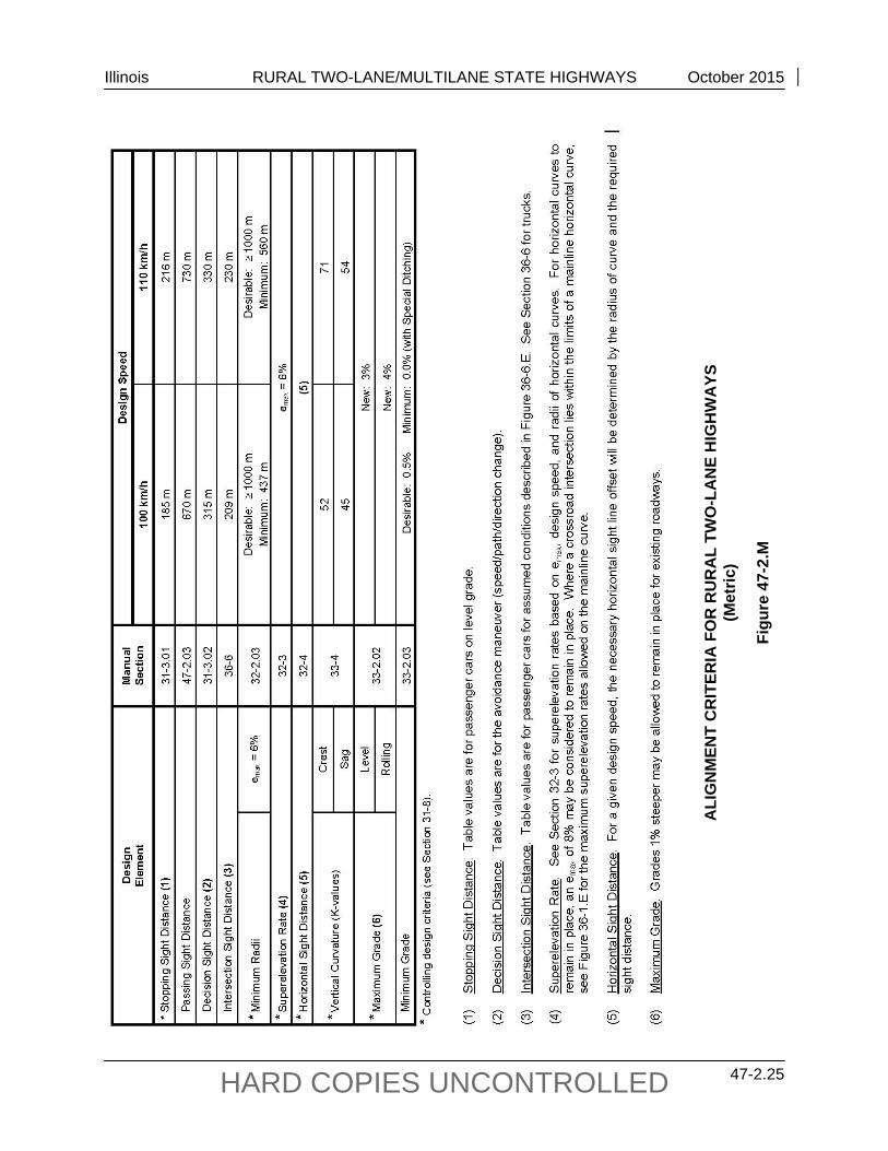
ALI
GN
MEN
T C
RIT
ERIA
FO
R R
UR
AL
TWO
-LA
NE
HIG
HW
AYS
(M
etric
)
Figu
re 4
7-2.
M
Illinois RURAL TWO-LANE/MULTILANE STATE HIGHWAYS October 2015
47-2.26 HARD COPIES UNCONTROLLED

Illinois RURAL TWO-LANE/MULTILANE STATE HIGHWAYS November 2014
47-3.1 HARD COPIES UNCONTROLLED
47-3 MULTILANE HIGHWAYS
47-3.01 General
New rural four-lane highways with depressed medians and without access control are not a common highway design in Illinois. For construction or reconstruction projects, the following are descriptions of some of the more likely situations where a four-lane highway design might be proposed:
1. SRA Routes. Where rural routes are designated as Strategic Regional Arterials (SRA). See Chapter 46 for the details of SRA design.
2. Suburban Areas. Where highways are located in an open-suburban area, where reconstruction is required to satisfy capacity demands, and where a design speed of 50 mph (80 km/h) is desired. These highways will most likely be classified as either a minor arterial or as a collector route. Chapter 43 discusses open-suburban guidelines, and Chapter 34 provides general cross section information.
3. Passing Lanes. Where passing lanes are needed in both directions on a two-lane highway and right-of-way and topography favor using a four-lane section. Also, more desirable traffic operations can be accomplished by designing a four-lane section which consists of side-by-side passing lanes; see Figure 47-2.F.
47-3.02 Design Speed
The selected design speed depends on the type of proposed project and on the following:
1. Rural SRA. Where an arterial route is designated as a rural SRA, the desirable design speed for new and existing roadways is 60 mph (100 km/h). To determine the minimum elements allowed to remain in place in conjunction with the design speed, see Section 45-2.02.
2. Open Suburban Area. Where a route is proposed for reconstruction in an open-suburban area and a high-speed design is preferred, use a rural-type cross section with a 50 mph (80 km/h) design speed. See Section 34-3.04(c) for the median design details and Figure 47-3.C for other geometric elements.
3. Passing Lanes. Where a two-lane highway requires additional passing opportunities and side-by-side passing lanes are proposed, provide a design speed of 60 mph (100 km/h) or greater. See Section 47-2.04 for design details.
47-3.03 Typical Sections
Figures 47-3.A and 47-3.B illustrate typical schematic cross sections for rural multilane highways. The tables in Section 47-3.04 provide the minimum criteria for lane widths, shoulder widths, median widths, and other cross section elements.
Illinois RURAL TWO-LANE/MULTILANE STATE HIGHWAYS November 2014
47-3.2 HARD COPIES UNCONTROLLED
47-3.04 Tables of Design Criteria
Figures 47-3.C and 47-3.D present the Department’s design criteria for rural multilane highways. Note that Figure 47-3.C also provides criteria for an existing roadway to remain in place. The designer should realize that some of the cross section elements included in the figures (e.g., flush concrete barrier) are not automatically warranted in the project design. The values in the figures only apply after the decision has been made to include the element in the highway cross section.

Illinois RURAL TWO-LANE/MULTILANE STATE HIGHWAYS November 2014
47-3.3 HARD COPIES UNCONTROLLED
Not
e:
See
Fig
ure
45-2
.C fo
r des
ign
of fl
ush
med
ians
with
con
cret
e ba
rrie
r.
TYPI
CA
L TA
NG
ENT
SEC
TIO
N F
OR
RU
RA
L M
ULT
ILA
NE
HIG
HW
AYS
(D
epre
ssed
Med
ian)
Figu
re 4
7-3.
A

Illinois RURAL TWO-LANE/MULTILANE STATE HIGHWAYS November 2014
47-3.4 HARD COPIES UNCONTROLLED
TYPI
CA
L SE
CTI
ON
FO
R S
UPE
REL
EVA
TED
RU
RA
L M
ULT
ILA
NE
HIG
HW
AYS
(D
epre
ssed
Med
ian)
Figu
re 4
7-3.
B
Not
e:
See
Fig
ure
45-2
.F fo
r des
ign
of fl
ush
med
ians
with
con
cret
e ba
rrie
r.

Illinois RURAL TWO-LANE/MULTILANE STATE HIGHWAYS November 2014
47-3.5 HARD COPIES UNCONTROLLED
GEO
MET
RIC
DES
IGN
CR
ITER
IA F
OR
RU
RA
L FO
UR
-LA
NE
MIN
OR
AR
TER
IALS
(N
ew C
onst
ruct
ion/
Rec
onst
ruct
ion)
(U
S C
usto
mar
y)
Figu
re 4
7-3.
C

Illinois RURAL TWO-LANE/MULTILANE STATE HIGHWAYS November 2014
47-3.6 HARD COPIES UNCONTROLLED
GEO
MET
RIC
DES
IGN
CR
ITER
IA F
OR
RU
RA
L FO
UR
-LA
NE
MIN
OR
AR
TER
IALS
(N
ew C
onst
ruct
ion/
Rec
onst
ruct
ion)
(M
etric
)
Figu
re 4
7-3.
C

Illinois RURAL TWO-LANE/MULTILANE STATE HIGHWAYS November 2014
47-3.7 HARD COPIES UNCONTROLLED
GEO
MET
RIC
DES
IGN
CR
ITER
IA F
OR
RU
RA
L FO
UR
-LA
NE
MIN
OR
AR
TER
IALS
(N
ew C
onst
ruct
ion/
Rec
onst
ruct
ion)
Foot
note
s fo
r Fig
ure
47-3
.C
(1)
Des
ign
Crit
eria
:
a.
Whe
n up
grad
ing
an e
xist
ing
two-
lane
hig
hway
to a
four
-lane
faci
lity,
use
the
crite
ria in
the
new
lane
s co
lum
n fo
r the
des
ign
of th
e ne
w ro
adw
ay
and
med
ian.
b.
The
crite
ria i
n th
is c
olum
n ar
e th
e m
inim
um c
ross
-sec
tion
elem
ents
allo
wed
to
rem
ain
in p
lace
for
rec
onst
ruct
ion
of a
n ex
istin
g ro
adw
ay
prov
ided
it is
cos
t effe
ctiv
e an
d sa
fety
reco
rd is
sat
isfa
ctor
y.
(2)
Traf
fic V
olum
es.
The
desi
gn h
ourly
vol
umes
(DH
V) a
ssum
es b
ase
cond
ition
s (e
xcep
t for
8%
hea
vy v
ehic
les)
and
a P
HF
= 1.
0. A
djus
t the
se v
alue
s us
ing
loca
l fac
tors
. (3
) D
esig
n S
peed
. To
det
erm
ine
the
min
imum
des
ign
spee
d al
low
ed to
rem
ain,
see
Sec
tion
45-2
.02.
(4
) A
cces
s C
ontro
l. In
vest
igat
e an
d co
nsid
er p
rovi
ding
par
tial a
cces
s co
ntro
l; se
e S
ectio
ns 4
5-2.
06 th
roug
h 45
-2.0
9.
Byp
asse
s ar
ound
a c
omm
unity
sh
ould
be
fully
acc
ess
cont
rolle
d if
the
inst
alla
tion
of tr
affic
sig
nals
is li
kely
at a
ny in
ters
ectio
n du
ring
the
20-y
ear d
esig
n pe
riod.
(5
) S
houl
der W
idth
(Lef
t). I
n m
ost c
ases
, lef
t sho
ulde
rs s
houl
d be
6 ft
(1.8
m) w
ide.
Thi
s al
low
s fo
r the
use
of 1
V:6
H s
lope
s in
the
med
ian.
How
ever
, if
the
20-y
ear l
evel
of s
ervi
ce a
ppro
ache
s Le
vel C
, the
n co
nsid
er a
8 ft
(2.4
m) w
ide
left
shou
lder
, and
dec
reas
e th
e m
edia
n sl
opes
to 1
V:5
H.
(6)
Trav
el L
ane
Cro
ss S
lope
. Fo
r eac
h ad
ditio
nal l
ane
away
from
the
crow
n la
nes,
incr
ease
the
cros
s sl
ope
by 1
/16
/ft (0
.5%
) per
add
ition
al la
ne u
p to
a
max
imum
of 5
/16
/ft (2
.5%
). (7
) D
epre
ssed
Med
ian
Wid
th.
a.
Med
ian
wid
th b
ased
on
1V:5
H m
edia
n sl
opes
, 2 ft
(600
mm
) ditc
h w
idth
, 3 ft
(900
mm
) ditc
h de
pth,
and
6 ft
(1.8
m) l
eft s
houl
ders
.
b.
Med
ian
wid
th b
ased
on
1V:5
H m
edia
n sl
opes
, exi
stin
g 2
ft (6
00 m
m) d
itch
wid
th, 3
ft (9
00 m
m) d
itch
dept
h, a
nd 4
ft (1
.2 m
) lef
t sho
ulde
rs..
(8)
Flus
h M
edia
n W
idth
. O
nly
use
flush
med
ians
with
CM
B w
here
rig
ht-o
f-way
or
topo
grap
hy r
estri
cts
the
use
of a
dep
ress
ed m
edia
n.
Con
side
r pr
ovid
ing
wid
er m
edia
ns w
here
requ
ired
for s
now
sto
rage
. (9
) C
lear
Zon
e. T
he c
lear
zon
e w
ill va
ry a
ccor
ding
to d
esig
n sp
eed,
traf
fic v
olum
es, s
ide
slop
es, a
nd h
oriz
onta
l cur
vatu
re.
(10)
D
itch
Bot
tom
Wid
th.
Pro
vide
a w
ider
out
side
ditc
h bo
ttom
whe
re d
eten
tion
stor
age
of s
torm
wat
er is
a c
onsi
dera
tion.
(1
1)
Bac
k S
lope
. W
here
the
heig
ht o
f cut
exc
eeds
10
ft (3
m),
cons
ider
usi
ng a
1V:
2H b
ack
slop
e be
yond
the
clea
r zon
e. A
lso,
for h
eigh
ts g
reat
er th
an
30 ft
(9 m
), co
nsid
er th
e us
e of
ben
chin
g.
(12)
Fi
ll S
lope
. Fo
r fil
l hei
ghts
gre
ater
tha
n 30
ft (
9 m
), us
e a
1V:2
H u
nifo
rm s
lope
with
a r
oads
ide
barri
er.
Als
o, fo
r he
ight
s gr
eate
r th
an 3
0 ft
(9 m
), co
nsid
er th
e us
e of
ben
chin
g.

Illinois RURAL TWO-LANE/MULTILANE STATE HIGHWAYS November 2014
47-3.8 HARD COPIES UNCONTROLLED
GEO
MET
RIC
DES
IGN
CR
ITER
IA F
OR
RU
RA
L FO
UR
-LA
NE
MIN
OR
AR
TER
IALS
(N
ew C
onst
ruct
ion/
Rec
onst
ruct
ion)
Foot
note
s fo
r Fig
ure
47-3
.C
(Con
tinue
d)
(13)
N
ew a
nd R
econ
stru
cted
Brid
ge W
idth
s.
Cle
ar r
oadw
ay b
ridge
wid
ths
are
mea
sure
d fro
m fa
ce to
face
of p
arap
ets
or r
ails
. B
ridge
wid
ths
are
norm
ally
def
ined
as
the
sum
of t
he a
ppro
ach
trave
led
way
wid
th a
nd th
e w
idth
of t
he p
aved
sho
ulde
rs.
See
Fig
ure
39-6
.A.
(14)
E
xist
ing
Brid
ge W
idth
s to
Rem
ain
in P
lace
:
a.
Cle
ar ro
adw
ay b
ridge
wid
ths
mea
sure
d fro
m fa
ce to
face
of p
arap
ets
or ra
ils.
Impl
ies
elem
ents
allo
wed
to re
mai
n in
pla
ce w
ithou
t a d
esig
n ex
cept
ion
whe
n co
st e
ffect
ive
and
whe
n sa
fety
reco
rd is
sat
isfa
ctor
y. S
ee F
igur
e 39
-6A
.
b.
Brid
ges
with
tota
l len
gths
gre
ater
than
250
ft (
75 m
) or
any
spa
n lo
nger
than
120
ft (
36 m
) ty
pica
lly s
houl
d ha
ve a
cle
ar r
oadw
ay b
ridge
w
idth
of 3
8 ft
(11.
4 m
) or 4
0 ft
(12.
0 m
). (1
5)
Ver
tical
Cle
aran
ce (A
rteria
l Und
er).
a.
Th
e cl
eara
nce
mus
t be
avai
labl
e ov
er th
e tra
vele
d w
ay a
nd a
ny p
aved
sho
ulde
r.
b.
Tabl
e va
lue
incl
udes
allo
wan
ce fo
r fut
ure
over
lays
.

Illinois RURAL TWO-LANE/MULTILANE STATE HIGHWAYS November 2014
47-3.9 HARD COPIES UNCONTROLLED
ALI
GN
MEN
T C
RIT
ERIA
FO
R R
UR
AL
FOU
R-L
AN
E M
INO
R A
RTE
RIA
LS
(US
Cus
tom
ary)
Figu
re 4
7-3.
D

Illinois RURAL TWO-LANE/MULTILANE STATE HIGHWAYS November 2014
47-3.10 HARD COPIES UNCONTROLLED
ALI
GN
MEN
T C
RIT
ERIA
FO
R R
UR
AL
FOU
R-L
AN
E M
INO
R A
RTE
RIA
LS
(Met
ric)
Figu
re 4
7-3.
D

Illinois RURAL TWO-LANE/MULTILANE STATE HIGHWAYS September 2012
47-4.1 HARD COPIES UNCONTROLLED
47-4 REFERENCES
1. A Policy on Geometric Design of Highways and Streets, AASHTO, 2011.
2. Low-Cost Methods for Improving Traffic Operations on Two-Lane Roads: Informational Guide, Report No. FHWA-IP-87-2, FHWA, 1987.
3. Highway Capacity Manual 2010, Transportation Research Board, 2010.
4. NCHRP 605 Passing Sight Distance Criteria, TRB, 2008.
Illinois RURAL TWO-LANE/MULTILANE STATE HIGHWAYS September 2012
47-4.2 HARD COPIES UNCONTROLLED