Embed Size (px)
Citation preview

RUNTIME DETECTION OF A BANDWIDTH DENIAL ATTACK FROM A
ROGUE NETWORK-ON-CHIP
by
Rajesh JayashankaraShridevi
A thesis submitted in partial fulfillmentof the requirements for the degree
of
MASTER OF SCIENCE
in
Computer Engineering
Approved:
Dr. Koushik Chakraborty Dr. Sanghamitra RoyMajor Professor Committee Member
Dr. Rajnikant Sharma Dr. Mark R. McLellanCommittee Member Vice President for Research and
Dean of the School of Graduate Studies
UTAH STATE UNIVERSITYLogan, Utah
2015

ii
Copyright c© Rajesh JayashankaraShridevi 2015
All Rights Reserved
iii
Abstract
Runtime Detection of a Bandwidth Denial Attack from a Rogue Network-on-Chip
by
Rajesh JayashankaraShridevi, Master of Science
Utah State University, 2015
Major Professor: Dr. Koushik ChakrabortyDepartment: Electrical and Computer Engineering
Network-on-Chip, the de-facto industry standard for connecting on-chip components
in forthcoming System-on-Chips plays a central role in providing a robust, reliable and
secure communication fabric. Conceptual similarities of NoCs to well established computer
networks makes the former vulnerable to security threats similar to those confronted during
the evolution of computer networks. Further, growing importance of NoC has triggered a
constant scrimmage between exploiting new potent security threats and identification of
techniques to prevent these threats.
This work explores a covert threat model for multi-processor system on chips de-
signed using 3rd party NoCs. The proposed malicious NoC can disrupt the availability of
on-chip resources, thereby causing large performance bottlenecks for software running on
MPSoC platform. This research rationalizes the potency and relevance of such threat and
propose techniques that enables a MPSoC integrator to monitor the trustworthiness of the
deployed NoC throughout the chip lifetime.
(56 pages)

iv
Public Abstract
Runtime Detection of a Bandwidth Denial Attack from a Rogue Network-on-Chip
by
Rajesh JayashankaraShridevi, Master of Science
Utah State University, 2015
Major Professor: Dr. Koushik ChakrabortyDepartment: Electrical and Computer Engineering
Chips with high computational power are the crux of today’s pervasive complex dig-
ital systems. Microprocessor circuits are evolving towards many core designs with the
integration of hundreds of processing cores, memory elements and other devices on a sin-
gle chip to sustain high performance computing while maintaining low design costs. Two
decisive paradigm shifts in the semiconductor industry have made this evolution possible:
(a) architectural and (b) organizational.
At the heart of the architectural innovation is a scalable high speed data communica-
tion structure, the network-on-chip (NoC). NoC is an interconnect network for the glueless
integration of on-chip components in the modern complex communication centric designs.
In the recent days, NoC has replaced the traditional bus based architecture owing to its
structured and modular design, scalability and low design cost. The organizational revo-
lution has resulted in a globalized and collaborative supply chain with pervasive use of
third party intellectual properties to reduce the time-to-market and overall design costs.
Despite the advantages of these paradigm shifts, modern system-on-chips pose a
plethora of security vulnerabilities. This work explores a threat model arising from a
malicious NoC IP embedded with a hardware trojan affecting the resource availability
of on-chip components. A rigorous simulation infrastructure is established to evaluate

v
the feasibility and potency of such an attack. Further, a non-invasive runtime monitoring
technique is proposed and thoroughly investigated to ensure the trustworthiness of a third
party NoC IP with low overheads.

vi
Acknowledgments
I would like to express my sincere gratitude to my adviser, Dr. Chakraborty, for his
insightful advice and patient guidance. Without his motivation and insights this work
would have never been complete. Also, I would like to thank Dr. Roy for her useful cri-
tiques of this research, as well as her valuable inputs which helped me tremendously in
framing this work. Also, I would like to express my appreciation to my committee mem-
ber: Dr. Rajnikant Sharma, for his valuable comments on this research. I would like to
thank various student members of Bridge Lab for their constant support, encouragement,
as well as making Bridge Lab such a pleasant and rewarding place to work. Specifically, I
would like to thank Dean for his technical guidance throughout this research, Yiding and
Hu for their constant support. I wish also to acknowledge the help provided by Manzi,
Chidambaranathan, Prabal, Shamik, Kurt, Harshitha, Brian, and Shayan. I would like to
express my great appreciation to the ECE department and all of the staff members, for of-
fering me this opportunity of Masters research, as well as the financial assistance towards
my tuition. I am particularly grateful for the assistance given by Mary Lee Anderson and
Tricia Brandenburg, who have helped me through numerous paper works and format-
ting of the dissertation. I would also like to extend my thanks to Trent Johnson and Scott
Kimber for providing technical support and maintaining the computer laboratory.
Last but not least, special thanks to my parents and my brother Swamy for their con-
stant support, encouragement and guidance throughout my study.
Rajesh Jayashankara Shridevi

vii
Contents
Page
Abstract . . . . . . . . . . . . . . . . . . . . . . . . . . . . . . . . . . . . . . . . . . . . . . . . . . . . . . . . . . . iii
Public Abstract . . . . . . . . . . . . . . . . . . . . . . . . . . . . . . . . . . . . . . . . . . . . . . . . . . . . . . iv
Acknowledgments . . . . . . . . . . . . . . . . . . . . . . . . . . . . . . . . . . . . . . . . . . . . . . . . . . . vi
List of Tables . . . . . . . . . . . . . . . . . . . . . . . . . . . . . . . . . . . . . . . . . . . . . . . . . . . . . . . . ix
List of Figures . . . . . . . . . . . . . . . . . . . . . . . . . . . . . . . . . . . . . . . . . . . . . . . . . . . . . . . x
Acronyms . . . . . . . . . . . . . . . . . . . . . . . . . . . . . . . . . . . . . . . . . . . . . . . . . . . . . . . . . . xi
1 Introduction . . . . . . . . . . . . . . . . . . . . . . . . . . . . . . . . . . . . . . . . . . . . . . . . . . . . . 11.1 Organization of the Thesis . . . . . . . . . . . . . . . . . . . . . . . . . . . . . 2
2 Background . . . . . . . . . . . . . . . . . . . . . . . . . . . . . . . . . . . . . . . . . . . . . . . . . . . . . . 42.1 Network-on-chip . . . . . . . . . . . . . . . . . . . . . . . . . . . . . . . . . . 4
2.1.1 Evolution of NoC . . . . . . . . . . . . . . . . . . . . . . . . . . . . . . 42.1.2 Conceptual View of the NoC . . . . . . . . . . . . . . . . . . . . . . . 52.1.3 Advantages of NoC . . . . . . . . . . . . . . . . . . . . . . . . . . . . 8
2.2 Collaborative Innovation Model in the Semiconductor Industry . . . . . . . 92.3 Literature Review . . . . . . . . . . . . . . . . . . . . . . . . . . . . . . . . . . 10
2.3.1 Stage of Trojan Insertion . . . . . . . . . . . . . . . . . . . . . . . . . . 112.3.2 Source of Threat . . . . . . . . . . . . . . . . . . . . . . . . . . . . . . . 122.3.3 Nature and Potency of Attack . . . . . . . . . . . . . . . . . . . . . . . 122.3.4 NoC Security . . . . . . . . . . . . . . . . . . . . . . . . . . . . . . . . 12
3 rNoC design . . . . . . . . . . . . . . . . . . . . . . . . . . . . . . . . . . . . . . . . . . . . . . . . . . . . . 15
3.1 Operational Phases . . . . . . . . . . . . . . . . . . . . . . . . . . . . . . . . . 153.2 Realizing a rNoC . . . . . . . . . . . . . . . . . . . . . . . . . . . . . . . . . . 16
3.2.1 Activation Module . . . . . . . . . . . . . . . . . . . . . . . . . . . . . 163.2.2 Victim IP Selection . . . . . . . . . . . . . . . . . . . . . . . . . . . . . 173.2.3 Traffic Flow Manipulation . . . . . . . . . . . . . . . . . . . . . . . . . 18
3.3 rNoC: Threat Model and Potency . . . . . . . . . . . . . . . . . . . . . . . . . 193.3.1 Potency Evaluation Methodology . . . . . . . . . . . . . . . . . . . . 203.3.2 Results and Significance . . . . . . . . . . . . . . . . . . . . . . . . . . 213.3.3 Area and Power Footprint . . . . . . . . . . . . . . . . . . . . . . . . . 213.3.4 Third-Party NoC IP Usage Trend . . . . . . . . . . . . . . . . . . . . . 22
viii
4 Runtime Latency Auditor for NoCs (RLAN) . . . . . . . . . . . . . . . . . . . . . . . . . . . . . 234.1 Design Challenges . . . . . . . . . . . . . . . . . . . . . . . . . . . . . . . . . 234.2 Design of RLAN . . . . . . . . . . . . . . . . . . . . . . . . . . . . . . . . . . . 24
4.2.1 Tagging Timestamps . . . . . . . . . . . . . . . . . . . . . . . . . . . . 254.2.2 Creating Source/Destination in RLAN . . . . . . . . . . . . . . . . . 26
4.3 Variants of RLAN . . . . . . . . . . . . . . . . . . . . . . . . . . . . . . . . . . 284.4 Scalability of RLAN . . . . . . . . . . . . . . . . . . . . . . . . . . . . . . . . . 294.5 Role of the SoC Firmware . . . . . . . . . . . . . . . . . . . . . . . . . . . . . 31
5 Methodology . . . . . . . . . . . . . . . . . . . . . . . . . . . . . . . . . . . . . . . . . . . . . . . . . . . . . 32
6 Results . . . . . . . . . . . . . . . . . . . . . . . . . . . . . . . . . . . . . . . . . . . . . . . . . . . . . . . . . 33
6.1 Efficacy . . . . . . . . . . . . . . . . . . . . . . . . . . . . . . . . . . . . . . . . 336.2 Multiple Application Environment . . . . . . . . . . . . . . . . . . . . . . . . 356.3 CDF-NLD Threshold . . . . . . . . . . . . . . . . . . . . . . . . . . . . . . . . 366.4 Performance Overhead . . . . . . . . . . . . . . . . . . . . . . . . . . . . . . . 376.5 Area and Power . . . . . . . . . . . . . . . . . . . . . . . . . . . . . . . . . . . 37
7 Conclusion . . . . . . . . . . . . . . . . . . . . . . . . . . . . . . . . . . . . . . . . . . . . . . . . . . . . . . 39
References . . . . . . . . . . . . . . . . . . . . . . . . . . . . . . . . . . . . . . . . . . . . . . . . . . . . . . . . . 40
ix
List of Tables
Table Page
2.1 Comparison of Threats in NoCs. . . . . . . . . . . . . . . . . . . . . . . . . . 14
6.1 False Positive (FP) and False Negative (FN) rates . . . . . . . . . . . . . . . . 37
6.2 Power Overhead due to RLAN configurations . . . . . . . . . . . . . . . . . 38

x
List of Figures
Figure Page
2.1 Paradigm shift from bus based architecture to interconnect networks . . . . 6
2.2 Block diagram of typical virtual channel NoC router . . . . . . . . . . . . . . 7
2.3 A typical packet format used in NoC communication . . . . . . . . . . . . . 7
2.4 Examples for network-on-chip topologies . . . . . . . . . . . . . . . . . . . . 8
2.5 Block diagram illustrating the SoC design flow . . . . . . . . . . . . . . . . . 10
3.1 rNoC router with the embedded hardware trojan . . . . . . . . . . . . . . . . 17
3.2 Hierarchical approach for Victim Selection in rNoC . . . . . . . . . . . . . . 18
3.3 Threat scenario : 3PIP vendor sabotaging a SoC integrator . . . . . . . . . . 20
3.4 Application performance degradation due to rNoC . . . . . . . . . . . . . . . 22
4.1 Real world example to illustrate RLAN technique . . . . . . . . . . . . . . . 25
4.2 Block diagram of SoC firmware with RLAN control . . . . . . . . . . . . . . 26
4.3 Overview and operation of RLAN . . . . . . . . . . . . . . . . . . . . . . . . 28
4.4 Detection point comparison for variants of RLAN . . . . . . . . . . . . . . . 30
4.5 Scalability of RLAN . . . . . . . . . . . . . . . . . . . . . . . . . . . . . . . . . 30
6.1 Efficacy of RLAN under single application environment . . . . . . . . . . . 34
6.2 Magnified cross-section of Figure 6.1 for analysis . . . . . . . . . . . . . . . . 34
6.3 Efficacy of RLAN under multi-program environment . . . . . . . . . . . . . 35
6.4 Magnified cross-section of Figure 6.3 for analysis . . . . . . . . . . . . . . . . 36
6.5 Runtime Overhead of the RLAN technique . . . . . . . . . . . . . . . . . . . 38

xi
Acronyms
3PIP third party intellectual property
CDF cumulative distribution function
DoS denial of service
FN false negative
FP false positive
IC integrated circuit
IP intellectual property
MPSoC multiprocessor system-on-chip
NLD network latency differential
NoC network-on-chip
PAP proximal analogous packet
QoS quality of service
RLAN runtime latency auditor for NoC
rNoC rogue network-on-chip
SoC system-on-chip
TTM time-to-market
VC virtual channel

1
Chapter 1
Introduction
Emerging global semiconductor environment represents a competitive arena where
the collaborative innovation model grows in prominence to sustain ubiquitous computing.
In the modern economic landscape, tightening supply chain budgets and growing design
complexity are the by-products of the semiconductor industry’s doctrine: smaller, faster and
cheaper. A remarkable technology trend that captures this interplay is the rapid growth in
demand for multi-processor system on chips (MPSoC) [1, 2]. With unprecedented pres-
sure of time-to-market, modern MPSoCs integrate many different Third Party Intellectual
Property (3PIP) components within a single die. These components are obtained from a
diverse pool of design houses, with a wide array of in-built functionality. Needless to say,
such a practice has far reaching implications toward the security and trustworthiness of
an entire chip [3–5]. Security assurance and verification of 3PIPs are challenging due to
the limited design information available from the respective 3PIP providers who want to
preserve their technological innovations. Consequently, many existing techniques based
on internal signal inspection are useless for detecting trojans embedded in 3PIP (e.g., [6]).
While many components in an MPSoC can be 3PIP, including the processing elements,
hardware accelerators, and memory modules, recent trends show a growing use of 3PIP
on-chip interconnects. Vast majority of these interconnect designs employ Network-on-Chip
(NoC), which facilitates glue-less integration of various hardware modules within a single
substrate. For example, Arteris, a NoCs IP provider, has experienced a tremendous growth
of 797% in their sales over the last few years [7]. Given this trend, it is now critical to
carefully consider the security implications of a 3PIP NoC in an MPSoC.
NoC 3PIPs present several unique challenges in trustworthy computing, compared to
3PIP processing elements, hardware accelerators, and memory modules. First, a NoC has

2
direct access to all the components in a SoC, and therefore plays a central role in resource
availability of a chip. Second, unlike processing elements or specialized components, there
is only one instance of a NoC in a MPSoC. Consequently, validating its security assurance
and performance guarantee becomes hard, as one cannot deploy 3PIP trustworthiness
based on replicated execution [1]. These unique aspects conspire to create a perfect secu-
rity storm when the NoC assumes a malicious role in a MPSoC. A rogue 3PIP NoC (rNoC)
can cause a plethora of damages like data corruption, denial of service, and information
stealing.
A secure system must provide three central aspects of trustworthiness: confidentiality,
integrity and availability [8]. This research focuses on the impact of rNoCs maliciously ma-
nipulating the availability of on-chip resources through a focused bandwidth denial attack
in the NoC. Such an attack can directly translate to application performance degradation in
modern many-core systems as they employ rudimentary in-order cores that lack the ability
to tolerate large on-chip communication latency [9,10]. Using rigorous circuit-architectural
methodology, it is demonstrated that a potent rNoC can be designed with a negligible foot-
print. Further, to counter this imminent threat, a novel run-time technique is proposed to
detect this attack and ascertain the trustworthiness of a NoC.
1.1 Organization of the Thesis
The rest of this thesis is organized as follows:
• Background: Chapter 2 equips the reader with necessary basics on the network-on-
chip and the backdrop of the system-on-chip (SoC) supply chain flow to reveal the
security loopholes. In order to show the novelty of this research, a thorough review
of the contemporary research in SoC and 3PIP security is presented.
• rNoC Design: In Chapter 3, the implementation details of the proposed threat model
is discussed. The rNoC’s potency and design footprint is investigated to show the
trojan’s feasibility and significance in modern SoC environment.

3
• RLAN Design: Chapter 4 details the proposed runtime latency monitoring tech-
nique to detect a focused bandwidth denial attack. The variants and scalability of
the non-invasive trojan detection technique are discussed in detail.
• Methodology: Chapter 5 describes the simulation infrastructure and the tools used
to evaluate the threat model and monitoring technique.
• Results: In Chapter 6, the efficacy of the proposed monitoring technique is evaluated
along with the overheads incurred for the security assurance of a 3PIP NoC. The
results indicate modest overheads of 12.73% in area, 9.84% in power and 5.4% in
terms of network latency.
• Conclusion: Chapter 7 concludes by highlighting the contribution of this research
and its significance in the modern MPSoC environment.

4
Chapter 2
Background
This chapter aims to establish the bedrock for the research presented in this thesis.
Section 2.1 presents an outline on the concepts of NoC and emphasizes on the advantages
of the NoC fabric in emerging MPSoCs. Section 2.2 scrutinizes the collaborative innovation
model and globalized supply chain adopted by the semiconductor industry to sustain high
performance computing. It further outlines the security loopholes that have surfaced as a
by-product of the newly adopted system-on-chip (SoC) supply chain model.
The comprehensive review of contemporary research presented in Section 2.3, under-
lines the novelty and importance of this research.
2.1 Network-on-chip
Network-on-chip is a layered and scalable on-chip communication fabric designed
to replace the traditional bus and crossbar based interconnection platforms in modern
many-core systems. Basic NoCs heavily borrow the concepts and techniques from the age-
old distributed computer networks paradigm. Critical parameters such as performance,
power consumption and reliability along with the fundamental differences between the
on-chip networks and computer networks has shaped the research in NoC domain. To
fully comprehend the operation and importance of a NoC, the section is further subdi-
vided to briefly outline the evolution of NoC (Section 2.1.1), present a conceptual view of
NoC, its components and operation (Section 2.1.2) and finally highlight the merits of NoC
(Section 2.1.3).
2.1.1 Evolution of NoC
The advent of sub nanometer semiconductor processing technology along with high

5
density transistor integration brought about several critical challenges to the fore. Firstly,
to meet the resource demands of growing computation-intensive applications and to sus-
tain high performance, the number of on-chip components and the design complexity of
a computing system increased exponentially. Secondly, with technology scaling, global
interconnect design issues of delay, power consumption, noise, scalability and reliability
began to plague the complex MPSoC designs. Thirdly, the traditional shared bus based
on-chip communication architectures where bus accesses by all connected components are
serialized, reached the limits of scalability. All these factors colluded together to cause
a critical bottleneck in system integration and productivity. To counter these crucial is-
sues and sustain high performance, researchers and industry experts conceived a shift in
the architectural paradigm (i.e, birth of on-chip interconnection network) as well as in
the organizational paradigm (growth of the collaborative innovation, described in Section
2.2). The birth of interconnection network encouraged the addition of more on-chip com-
ponents. Swiftly, NoC flourished as the de-facto standard for on-chip communication in
modern many-core computing systems.
2.1.2 Conceptual View of the NoC
Figure 2.1 illustrates the paradigm shift from bus based architecture to NoCs in many-
core systems as discussed above. A typical NoC constitutes multiple routers and network
interfaces (NI) that connect different intellectual property (IP) blocks through physical
links (wires). An IP block and NI are together known as a tile/node. A closer look at
the building blocks of a NoC follows:
• Router : A typical NoC router consists of buffers, an interconnection matrix, func-
tional and control units. Figure 2.2 shows the block diagram of a typical virtual-
channel router broadly partitioned as datapath and control plane. The datapath consists
of input buffers, crossbar and the output buffers and as the name suggests it handles
the storage and movement of packets of data/signal. The control plane on the other
hand, consists of route calculation, virtual channel (VC) allocation and switch alloca-

6
PE 1 PE 2
PE 3 PE 4
C�O���A�
S�I���
L1 Cache L1 Cache
L1 Cache L1 Cache
ME
MO
RY
CO
NT
RO
LL
ER
QU
EU
E, U
NP
E &
I/O
SHA
RE
D C
AC
HE
Designer components
R
R
R
R
R
R
R
R
R
PEL1 Cache
PEL1 Cache
PEL1 Cache
PEL1 Cache
PEL1 Cache
PEL1 Cache
PEL1 Cache
PEL1 Cache
PEL1 Cache
R
R
R
R
R
R
�
�
R
PE
PE
MC PE
HA
MC PE
PE
PE
R
R
R
MC
PE
MC
R R R
HA PE PE
R
PE
HA PE
PE MC
R 3rd Party IP components
~2000: multicore
bus based designs
~2010: many core
NoC centric design
~2015: MPSoC
NoC centric + 3rd party IP
Fig. 2.1: Paradigm shift from bus based architecture to interconnect networks. Bus basedarchitecture design connecting a few cores (e.g., Intel nehalem) was replaced by NoC cen-tric designs connecting many cores (e.g., Intel SCC). To maintain high performance com-puting at low design cost emphasis is shifting towards pervasive use of 3rd party IPs.
tion blocks. These blocks make decisions pertaining to the route taken by the packets
and also manage arbitration and resource allocation when multiple packets contend
for limited physical resources.
Each flit 1 of a packet 2 arrives at the input buffers of a router from an upstream router.
The route computation module determines the output port to which the packet must
be forwarded. The packet then requests for an output virtual channel and the VC
allocation module allocates the required resource after evaluating all requests. The
switch allocation module provides a time slot during which each flit of a packet is
forwarded from the input buffers to the output port. Finally, the flits are transmitted
from the output buffers to the downstream router’s input port.
• Network Interface : NI serves as the interface between the communication network
and the IP blocks. NI generally handles the packetization, packet re-ordering and
1Flit: Flow control digit, is the smallest unit of data recognized by the flow control method2Packet: A fixed length of flits, that encapsulates the information to be transmitted along with destination
address and other critical information

7
Route Computation
VC Allocator
Switch Allocator
CONTROL PLANE
DATAPATH
C�O���A�
SW����
V� �
�
V� �
V� �
V�
V� �
Input 1
Input 5
Output 1
Output 5
INPUT BUFFERS
Fig. 2.2: Block diagram of typical virtual channel NoC router.
retransmissions. It splits the incoming data into packets and augments critical infor-
mation required for routing the packets to the correct destination. Along with the
destination address, the NI can augment error detection/correction information and
any other monitoring information required by the designer into the packet header.
Figure 2.3 illustrates an example packet format for the NoC.
• Link : Links are the physical wires connecting the routers in a network. There exists
two kinds of links: serial and parallel.
NoCs can be tuned in a variety of parameters such as topology, buffering, data widths,
arbitration techniques, routing algorithms, etc. based on the application requirement. An
Fig. 2.3: A typical packet format used in NoC communication.

8
overview of important architectural aspects follows:
• Topology : Topology determines the physical layout and the connections between
network components. Figure 2.4 illustrates some of the well-known topologies. The
topology choice depends on the cost-performance trade off of the applications.
• Routing : Routing algorithms compute the path taken by the data from the source to
destination. Routing algorithms have been efficiently used to increase performance
under different load scenarios (congestion based routing algorithms e.g., [11–13]
among others), provide fault tolerance (e.g., [14–16], etc.) and improve reliabil-
ity [17, 18].
• Flow Control : Flow control ensures the effective utilization of network resources
such as buffers and link bandwidth, thereby play a critical role in determining the
performance and power consumption of a NoC. Some typical flow control tech-
niques are circuit-switching (message based), store-and-forward (packet based) and
wormhole (flit based).
2.1.3 Advantages of NoC
A summary of the benefits of the NoC architecture in modern MPSoCs are as follows:
Fig. 2.4: Examples for network-on-chip topologies: 3x3 mesh, 3x3 torus, 3-fly-2-ary butter-fly and irregular network.

9
• Abstraction : NoCs provide a clear demarcation between computation and commu-
nication in a MPSoC.
• Structured and Customizable : The NoC topology, buffer size, data widths, routing
algorithms and various other parameters are customizable according to application
requirement and have a lower complexity due to a structured design.
• Parallelism : Concurrent spatial reuse of links and routers allow parallelism in data
flow.
• Scalable : NoC architecture can be scaled to accommodate hundreds of on-chip com-
ponents. They exhibit better performance under load as communication flows can
be handled in parallel.
• Wire Routing Congestion : NoC significantly reduces the number of wires required
to route data and signals in a SoC thereby increasing wire utilization and efficiency.
• Modular : NoC architecture makes it easy to swap different IP blocks and create
derivative chips based on the need of each application. This in turn reduces the
time-to-market (TTM) due the modular nature of system design and increases pro-
ductivity.
2.2 Collaborative Innovation Model in the Semiconductor Industry
Globalization, rapidly changing consumer demands, shrinking product life cycles and
fierce competition has changed the dynamics and organization of the semiconductor in-
dustry’s supply chain. Integrated circuits (IC) are no longer designed and manufactured
by the same firm but the IC/SoC supply chain is distributed worldwide. Modern SoC de-
signs are a combination of numerous on-chip devices that come from various third party
design houses as well as those designed in-house. To keep pace with the consumer de-
mands, constantly reduce the time-to-market(TTM) and at the same time reduce cost of
design and manufacturing in the competitive market, semiconductor industry has adopted
a globalized collaborative innovation model where firms specialize in a specific stage or

10
specific component in the SoC design flow. Hence, many firms must work together to de-
velop, manufacture and supply a finished IC. Figure 2.5 illustrates the globally distributed
SoC design flow. The figure also shows that there are multiple stages within the supply
chain which are untrustworthy. The globalized supply chain is vulnerable to many dif-
ferent security threats such as IP piracy, reverse engineering, counterfeiting, insertion of
hardware trojans, etc. Researchers, academicians and industry experts have explored an
overabundance of threat models, metrics and remedies, but with the exponential growth in
the use of 3PIPs and deeper understanding of devices, more covert and potent threat mod-
els are conceived. With billions of dollars spent for security assurance in today’s environ-
ment, it is imperative to investigate low cost and low overhead techniques to strengthen
the trustworthiness and ensure secure system designs.
2.3 Literature Review
This section presents a comprehensive study of contemporary works related to this
research. As seen above, security assurance of on-chip hardware components is an obstacle
of growing magnitude and importance. The contemporary research in hardware security
Fig. 2.5: Block diagram illustrating the SoC design flow.

11
can be broadly classified on three major axes based on their underlying assumptions:
• Stage of trojan insertion : Hardware trojans can be embedded in the integrated cir-
cuit in many stages during the life cycle of chip design and manufacturing process
(Section 2.3.1).
• Source of threat : A potent hardware trojan can be effectively embedded in any of the
numerous on-chip components such as the processing elements, memory, hardware
accelerators, communication network, etc. (Section 2.3.2).
• Nature and potency of security violation : The nature of attack is limited only by the
trojan designer’s imagination and the trojan’s source. A plethora of potent attacks
such as information stealing, total chip failure, data manipulation, resource availability, etc.
can be envisaged (Section 2.3.3).
The first and second component can be assessed by inspecting the threat model pro-
posed in the work, where as the third component can be determined by understand-
ing the malicious activity from the perspective of the security properties of a system—
confidentially, integrity, and availability.
2.3.1 Stage of Trojan Insertion
Several recent works protect against untrusted foundries by detecting malicious cir-
cuit modifications (e.g., [19–24] among others). Further, there has also been research to
avoid cloning the chip design and counterfeiting using physically unclonable functions
(PUF) (e.g., [25–29], among others). But as semiconductor industry adopts the collaborative
innovation model, these mechanisms are ineffective to protect against design time mali-
cious 3PIP in an MPSoC. To offer security in such a scenario Chen et al. proposed task
duplication so as to verify the validity of one execution [1]. While this work is an im-
portant step forward in 3PIP security assurance, research in this domain needs immediate
attention to design novel and scalable solutions with low overhead.

12
2.3.2 Source of Threat
Security researchers and trojan designers have explored embedding the hardware tro-
jan in a variety of on-chip components. An overabundance of research focused on detec-
tion of trojans in processing and storage elements (e.g., [30–43]). As computing systems
evolved with the addition of more on-chip components research on hardware security
broadened with the aim to ensure trustworthiness. Similarly, with the advent of NoC, re-
search on NoC security gathered steam. Section 2.3.4 summarizes the recent works in NoC
security, highlighting the novelty and importance of the research presented in this thesis.
2.3.3 Nature and Potency of Attack
Hardware trojans can be designed to violate one of the three central aspects of trust-
worthiness: (a) confidentiality, (b) integrity, and (c) availability. Trojans that attack the con-
fidentiality of a system aim to steal data from on-chip devices either through direct in-
formation leakage or side channel analysis of signals and circuit behavior. Demme et
al. investigated metrics to measure information leakage attacks [44] while many research
works focused on detection and prevention of such attacks [45, 46]. Though theft of data
is the most profitable attack for a trojan designer, there have been several cases of covert
data manipulation. Previous works explore techniques to ensure data integrity in storage
memories [42, 47] and program code integrity [30, 48, 49]. Another class of trojans influ-
ence the availability of resources, making them unavailable when the system demands it.
Denial-of-service attacks are the most common type of attacks that affect resource avail-
ability. The potency of these trojan attacks can range from simple loss of performance and
energy efficiency to catastrophic system wide irreversible failures.
2.3.4 NoC Security
A vast majority of recent works assume a secure NoC, where the threat is assumed to
rise from the software or the processing elements. Data Protection Unit (DPU) proposed
by Fiorin et al. [50] and Secure Network Interface (SNI) by Diguet et al. [51]) are two such

13
works that analyze secure access control on memory banks. Few works employ encrypted
data transmission over the NoC (e.g., [52, 53]) or partition the NoC into separate zones
based on trust [54, 55]. On the other hand, some works have looked into creating efficient
chip resource partitioning to isolate secure and non-secure applications [54, 56]. These
works are also primarily concerned with the confidentiality of the data transmitted on the
system. Another class of works inspects security threats violating the availability of the on-
chip NoC bandwidth, and explores techniques within the scope of a secure NoC. Diguet et
al.’s work on SNI can protect from denial of service (DoS) attack caused by replay, livelock,
deadlock and incorrect path. Fiorin et al. propose the use of DoS probe as a part of the NoC
monitoring architecture [57]. Parallel to these works in security, there have been numerous
proposals to provide quality of service (QoS) guarantees in a NoC [58]. While these works
are conceptually closer to the work presented in this thesis, the proposed mechanisms
are impractical for the threat model explored in this work, as the NoCs derived from a
3PIP cannot be modified. Similarly, recent work by Ancajas et al. explores a rNoC [59], but
their threat model and protection mechanisms are focused on confidentiality and are unable
to detect or thwart malicious manipulation of resource availability from a rNoC. Table 2.1
summarizes the different threat in NoCs.
This work explores a new threat model based on a key underlying assumption: a
rogue NoC manipulating the availability of the on-chip communication bandwidth. With
NoCs being such an integral part of present and future MPSoCs, the need to investigate
trustworthiness of a third party NoC IP is immense. The work presented here is distinct
from contemporary secure 3PIP works, primarily in two aspects.
• In the light of proliferation of 3PIP NoCs, this research explores a threat where the
NoC is malicious. Consequently, unlike a majority of existing works, the security
measures cannot be placed inside the NoC architecture.
• The threat model presented in this research is concerned with the availability of on-
chip resources.

14
Table 2.1: Comparison of Threats in NoCs.
Trojan Locationa Attackb Protectionc Activationd
rNoC(This work) NoC Malign IP NI Time
DPU [50] [57] S/W IT(Mem)/DC/DoS NI —
surfNoC [54] S/W IT(S/W) NoC —
AE [53] S/W IT(Mem) NI —
IMP [60] µP IT(µP/Mem) — S/W
NoC-MPU [61] S/W IT(Mem) NI —a The part of the system where a trojan is inserted.b The type of attack carried out in the NoC.(IT-Information Theft,DoS-Denial of Service)c The part of the system where a protection mechanism is implemented to prevent an attack.d The activation mechanism employed in case of a hardware trojan.

15
Chapter 3
rNoC design
This Chapter discusses the design of the proposed rogue NoC (rNoC), elaborating
on its operational phases (Section 3.1), and the router micro-architecture modifications re-
quired for the implementation of the trojan (Section 3.2). Further, Section 3.3 discusses the
threat posed by a rNoC for the SoC integrators and other IP providers, demonstrates the
potency of the proposed rNoC design and motivates the need for research in this domain.
The trojan design overhead is evaluated in terms of area and power to show that a potent
rNoC can be designed with negligible footprint.
3.1 Operational Phases
A rNoC broadly follows a set of phases as described below.
• Trojan insertion: The NoC 3PIP provider creates a rNoC by inserting a malicious circuit
in the NoC router during the design or verification phase. The Trojan is designed to
engage in a focused bandwidth denial attack targeting either one or a few key on-chip
resources. This threat model can be realized by one or two malicious design and
verification engineers in the NoC IP design team [6].
• Identifying Client: The NoC provider must then identify a client SoC integrator to sup-
ply a rogue version of their IP. At first glance, this may appear counter-productive as
clearly the NoC IP provider may lose their SoC integrator client eventually. However,
given the growing role of a NoC 3PIP, other SoC integrators may pay off the NoC IP
provider for monopolizing a niche market. For example, in Figure 3.3, SoC Integrator
3 might pay off the NoC provider to victimize SoC Integrator 4, and steal its clients.
The notion of a disgruntled employee inserting a malicious design or a sabotage from
competitors to harm the company’s prospects is not new. Such practices have seen
16
the light of the day in other industries including the software domain [62, 63], and it
is not unreasonable to expect a similar trend in the hardware domain.
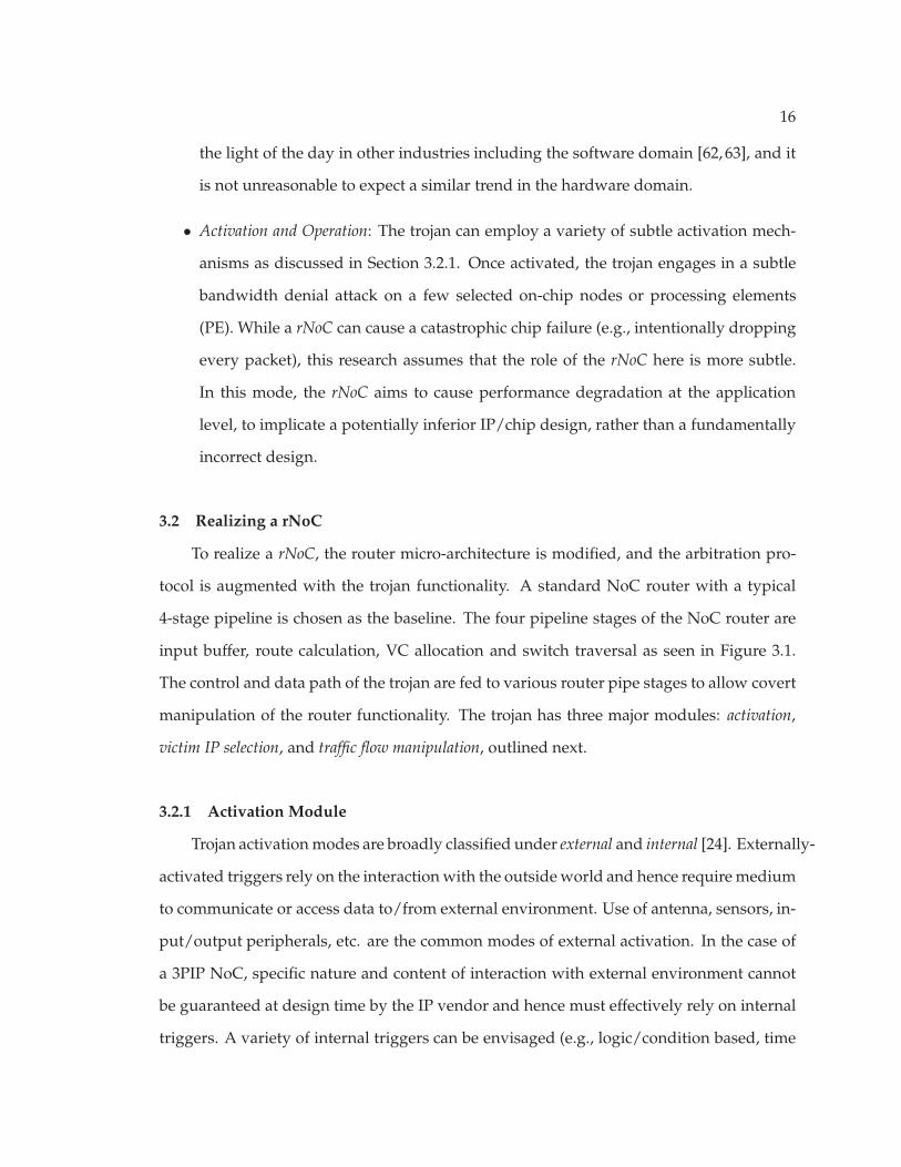
• Activation and Operation: The trojan can employ a variety of subtle activation mech-
anisms as discussed in Section 3.2.1. Once activated, the trojan engages in a subtle
bandwidth denial attack on a few selected on-chip nodes or processing elements
(PE). While a rNoC can cause a catastrophic chip failure (e.g., intentionally dropping
every packet), this research assumes that the role of the rNoC here is more subtle.
In this mode, the rNoC aims to cause performance degradation at the application
level, to implicate a potentially inferior IP/chip design, rather than a fundamentally
incorrect design.
3.2 Realizing a rNoC
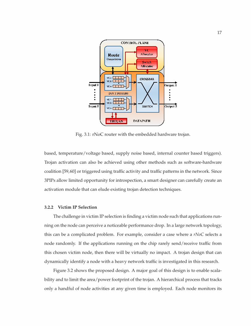
To realize a rNoC, the router micro-architecture is modified, and the arbitration pro-
tocol is augmented with the trojan functionality. A standard NoC router with a typical
4-stage pipeline is chosen as the baseline. The four pipeline stages of the NoC router are
input buffer, route calculation, VC allocation and switch traversal as seen in Figure 3.1.
The control and data path of the trojan are fed to various router pipe stages to allow covert
manipulation of the router functionality. The trojan has three major modules: activation,
victim IP selection, and traffic flow manipulation, outlined next.
3.2.1 Activation Module
Trojan activation modes are broadly classified under external and internal [24]. Externally-
activated triggers rely on the interaction with the outside world and hence require medium
to communicate or access data to/from external environment. Use of antenna, sensors, in-
put/output peripherals, etc. are the common modes of external activation. In the case of
a 3PIP NoC, specific nature and content of interaction with external environment cannot
be guaranteed at design time by the IP vendor and hence must effectively rely on internal
triggers. A variety of internal triggers can be envisaged (e.g., logic/condition based, time
17
Fig. 3.1: rNoC router with the embedded hardware trojan.
based, temperature/voltage based, supply noise based, internal counter based triggers).
Trojan activation can also be achieved using other methods such as software-hardware
coalition [59,60] or triggered using traffic activity and traffic patterns in the network. Since
3PIPs allow limited opportunity for introspection, a smart designer can carefully create an
activation module that can elude existing trojan detection techniques.
3.2.2 Victim IP Selection
The challenge in victim IP selection is finding a victim node such that applications run-
ning on the node can perceive a noticeable performance drop. In a large network topology,
this can be a complicated problem. For example, consider a case where a rNoC selects a
node randomly. If the applications running on the chip rarely send/receive traffic from
this chosen victim node, then there will be virtually no impact. A trojan design that can
dynamically identify a node with a heavy network traffic is investigated in this research.
Figure 3.2 shows the proposed design. A major goal of this design is to enable scala-
bility and to limit the area/power footprint of the trojan. A hierarchical process that tracks
only a handful of node activities at any given time is employed. Each node monitors its
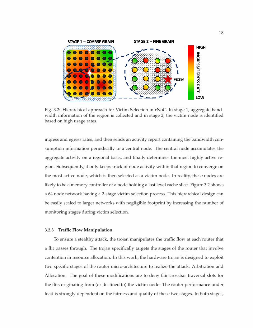
18
Fig. 3.2: Hierarchical approach for Victim Selection in rNoC. In stage 1, aggregate band-width information of the region is collected and in stage 2, the victim node is identifiedbased on high usage rates.
ingress and egress rates, and then sends an activity report containing the bandwidth con-
sumption information periodically to a central node. The central node accumulates the
aggregate activity on a regional basis, and finally determines the most highly active re-
gion. Subsequently, it only keeps track of node activity within that region to converge on
the most active node, which is then selected as a victim node. In reality, these nodes are
likely to be a memory controller or a node holding a last level cache slice. Figure 3.2 shows
a 64 node network having a 2-stage victim selection process. This hierarchical design can
be easily scaled to larger networks with negligible footprint by increasing the number of
monitoring stages during victim selection.
3.2.3 Traffic Flow Manipulation
To ensure a stealthy attack, the trojan manipulates the traffic flow at each router that
a flit passes through. The trojan specifically targets the stages of the router that involve
contention in resource allocation. In this work, the hardware trojan is designed to exploit
two specific stages of the router micro-architecture to realize the attack: Arbitration and
Allocation. The goal of these modifications are to deny fair crossbar traversal slots for
the flits originating from (or destined to) the victim node. The router performance under
load is strongly dependent on the fairness and quality of these two stages. In both stages,

19
inducing minor delay by unfair resource allocation to flits originating/destined from/to
victim IPs will remain inconspicuous and at the same time, inflicting flit delays at each
hop will have a significant effect on the packet latency. This distributed model of traffic
flow manipulation is harder to detect as it bears resemblance to delays due to resource
contention and can be misinterpreted as traffic congestion related delays.
• Arbiter: The role of an arbiter is to resolve multiple requests to a single resource
shared by many agents. In particular, arbiter allocates the virtual channel from in-
put buffer to output buffers for flit traversal. Round Robin (RR) is one of the com-
mon mechanisms used, which allows flits to reserve the crossbar traversal slots uni-
formly. To enable the attack, the trojan circuit de-prioritizes the flits destined to (or
sourced from) the victim node, deviating slightly from the uniform scheduling. Con-
sequently, flits may be delayed at a given router for a pre-designated number of cy-
cles. This delay must be restricted to a low number of cycles at each hop to prevent
it from being perceived as anomalous behavior.
• Allocator: An allocator matches resources to requesters under constraints to allow
flits to traverse through the crossbar. Flits must request the allocator for time slots
for the switch traversal. By suppressing the request made by a flit from the victim
node for a pre-determined number of cycles, the trojan induces a delay in allocation.
Since both stages are internal specifications of a router design, a SoC integrator will
not be able to inspect its fairness or operation. Unfortunately, a 3PIP rNoC cannot be de-
tected by internal signal inspection (e.g, [6]) as modern IP providers are reluctant to release
their proprietary RTL containing the internal specifics of the IP design.
3.3 rNoC: Threat Model and Potency
A rNoC poses a potent threat on the economic health of SoC integrators, as well as,
on other on-chip IP providers by directly controlling the perceived availability of various
on-chip resources. The performance of various applications on an MPSoC can often de-
pend heavily on a few IPs. For example, an application with a heavy memory footprint

20
has a strong dependence on the on-chip memory controllers, as well as, on SoC nodes with
cache slices housing pertinent data. If the traffic to these nodes are thwarted by a rNoC,
the application may suffer a substantial performance loss, resulting in potentially unhappy
clients for the SoC integrators. In this scenario, only applications with high memory re-
quirement suffers while other applications in the same network perform correctly. This
inconsistent behavior, combined with the lack of non-invasive techniques to introspect the
performance of each IP at runtime denounces the blame on a faulty memory controller,
memory module or an inefficient integration of 3PIP components. Figure 3.3 shows a clas-
sic scenario for this threat, where the SoC integrator 4 may suffer a hefty business loss due
to a rNoC.
3.3.1 Potency Evaluation Methodology
To evaluate the performance degradation seen by applications due to a focused band-
width denial attack from a rNoC, Booksim2.0—a cycle-accurate interconnection network
simulator— is used. Flit delays are simulated in the crossbar allocation stage, for those
Analog
MemHA
PE Analog
HA
AAAAAAAAAAAAAn
MMMMMMMMMMMMMAA
E
NoC
Mem
PE
Mem
SoC Integrator 2 SoC Integrator 3 SoC Integrator 4
PE
Pool of 3PIPs
NoC
Analog
3PIIPPss
C Analog
Analog
ooggggggg Analog
Mem
PPooool o
NNMem
PE PEAAAAAAAAAAAAAn
AA MMMMMMMMMMMMMM
EE
NoC
PE
HA
rNoC
HA HA
HA
E
MMMMMMMMMMMM
AAAAAAAAAAAAAn
AAAAAAA
NoC
MMA Mem Mem
SoC Integrator 1
Victimized
Fig. 3.3: Threat scenario : 3PIP vendor sabotaging a SoC integrator. A NoC provider se-lectively provides a rNoC to one of its SoC integrators. Subsequently, the rNoC causes abandwidth denial attack for applications running on the chip produced by the SoC inte-grator 4, damaging its reputation.

21
flits originating from a node under attack, and the average latency overhead of these pack-
ets are calculated. Booksim2.0 [64], coupled with network packet traces of multithreaded
applications in the PARSEC suite released by Netrace0.9 [65] is used to simulate real world
application behavior. To accurately model different degrees of the proposed distributed at-
tack and to estimate the potency, a range of delays (e.g., one cycle to four cycle delay per
flit at each hop) are inflicted on the flits belonging to the victim nodes. The results of these
simulations are discussed next.
3.3.2 Results and Significance
Figure 3.4 shows the increase in packet latency caused by bandwidth denial attacks.
The packet latency overhead ranges from 14.5% to 72%, based on the additional delay
inflicted per hop. It can be observed that the latency degradation remains fairly consis-
tent across benchmarks. These latency degradation directly translate to application perfor-
mance degradation in modern many-core systems, with rudimentary in-order cores that
are unable to hide on-chip communication latency. Given this remarkable threat potency
from a rNoC design on future MPSoC platforms, it is important to investigate the feasibility
and stealth of the trojan design embedded in the 3PIP NoC module.
3.3.3 Area and Power Footprint
The area and power footprint of the RTL design is carefully investigated to better
comprehend the trojan’s feasibility. To evaluate the overhead of the Trojan design footprint
in a NoC, the RTL of an open-source Stanford Verilog model of a modern NoC router [66]
is augmented with the modules described in Section 3.2. The router is used as a part of
a mesh topology with 5-input/output ports (4 cardinal directions + 1 local) and 5 virtual
channels in each port. The RTL design is synthesized with the TSMC 45nm library using
Synopsys Design Compiler. Synthesis results show that the embedded trojan design has
negligible overheads of 4.32% and 0.014% in area and power, respectively. Hence a rNoC
presents a potent threat to impact the performance while using a low design footprint.

22
blackscholes
bodytrack
canneal
fluida
nimate
swaptions vip
sx264
Avera
ge
Latency Degradation
0
10
20
30
40
50
60
70
80D1 D2 D3 D4
Fig. 3.4: Application performance degradation due to rNoC. Communication latencydegradation incurred due to bandwidth denial attack. [D1,D2,D3,D4] implies [1,2,3,4] cy-cle additional delay at each hop introduced by a 64-node rNoC.
3.3.4 Third-Party NoC IP Usage Trend
To fully comprehend the significance of rNoC, one needs to recognize the growth of
third-party NoC IPs. In the past decade, the use of NoC IPs in SoCs has grown exponen-
tially. The turn-key solutions provided by companies such as Sonics and Arteris enable
design firms to improve their methodology and shorten time-to-market schedules by al-
lowing ease of integration of different SoC components. NoC IPs are used increasingly
in a wide array of market segments such as mobile phones, tablets, automotive and gen-
eral purpose processing to name a few. In 2014, Gartner Inc–an independent technology
research firm–has ranked NoC IP sales of Sonics as #7 based on Design IP revenue with
a 44.8% profit growth compared to the previous year [67] and Arteris has experienced a
growth in sales of 797% over the last few years [7]. Given this ubiquity of IC devices us-
ing NoCs, it becomes more important to preserve the trustworthiness and security of such
systems. Hence, this work proposes a non-invasive runtime technique to detect focused
bandwidth denial attacks in a 3PIP NoCs.

23
Chapter 4
Runtime Latency Auditor for NoCs (RLAN)
This chapter details the proposed runtime technique RLAN to detect traffic abnormal-
ities in the NoC caused by a malicious NoC IP. While the performance degradation due to
unfair bandwidth allocation is evident at the application level (Section 3.3), runtime detec-
tion of such malicious activities has several key challenges, outlined in Section 4.1. These
challenges lay the foundation for the proposed technique RLAN (Section 4.2). RLAN is a
non-invasive technique that can work without any modification to a 3PIP NoC IP. To realize this
goal, the technique is integrated in the SoC firmware module that interfaces the process-
ing element to the network interface (NI) of the NoC IP. Section 4.3 discusses the RLAN
variants, while Section 4.4 and Section 4.5 outlines the scalability and role of SoC firmware
design.
4.1 Design Challenges
The crux of the detection technique is to identify the latency elongation of network
packets caused by a bandwidth denial attack. There are three key challenges in runtime
detection, outlined next.
• Understanding Attack Semantics: An ongoing attack on any given node cannot be de-
tected simply by comparing the latencies of various packets sourced (or destined) to
that node. This is because, once under attack, there will be little anomaly in latencies
between similar packets from/to the victim node, thereby defeating the purpose of
the detection mechanism. Also, comparing latencies of other packets in the network
will not serve the purpose due the difference in spatial and temporal characteristics
of the network.

24
• Limiting False Positives: False positives may arise because the latencies of network
packets between a given source-destination incur variations based on normal net-
work level activities. In particular, in an MPSoC environment, different applications
may coexist at different times, resulting in a wide variation in network level conges-
tion during their runtime. As a result, RLANs must distinguish latency elongation
due to normal network activities from those of malicious activities. Furthermore,
claiming a 3PIP provider is engaged in malicious activities has potential legal impli-
cations, and therefore must be backed by strong irrefutable evidence.
• Managing Overhead: To create a practical solution technique, it is critical to manage
its circuit-architectural overhead in terms of performance impact on other traffic, and
area and power. With growing network size, scalability of the proposed technique
is another important consideration. Several RLAN variants are explored to balance
overhead and efficacy in Section 4.3.
4.2 Design of RLAN
The insight of the proposed RLAN design is that packets traversing routes with significant
overlap (spatial similarity) around the same time (temporal similarity) have comparable latencies.
Figure 4.1 gives a real world example to illustrate the concept. At 5PM, the time taken
between the three routes between same source and destination varies. This is due to the
difference in spatial traffic congestion (spatial variation). Comparing just the highlighted
routes (similar routes) at 5PM and 3AM, it is seen that there is still a variation in the time
taken for the travel. The difference in traffic congestion at different times is responsible
for the effect (temporal variation). To counter these variations, RLAN uses routes with sig-
nificant overlap. This phenomenon is exploited to devise the proposed solution. Essen-
tially, given an existing packet, a Proximal Analogous Packet (PAP) is created by slightly
altering the source and/or destination. PAP have similar priority and hop count to the
original packets and contain information to help relate to their original counterparts. Sub-
sequently, the latencies of the original packets are compared to their Pips and statistics

25
are gathered over a significant sample size to detect malicious activities. The proposed
design involves two major steps: (a) Tagging timestamps (Section 4.2.1); and (b) Creating
source/destination in RLAN (Section 4.2.2).
4.2.1 Tagging Timestamps
To compare latencies, during the operational phase of RLAN, all packets are tagged
with a timestamp. Figure 4.2 illustrates the required design. During the operation, the
PE forwards the data to be communicated to the SoC Firmware, where a clock module
tags a timestamp and dispatches it to the NI for packetization and injection into the net-
work. At a destination, the incoming packet is depacketized in the NI and forwarded to
the SoC firmware where timestamps are extracted. By scrutinizing extracted timestamps,
RLAN establishes healthy interconnect latency thresholds and detects irregularities in the
NoC fabric. An auxiliary benefit obtained from tagging timestamps is isolation of com-
munication time from the computation time in a SoC. This aids in dynamic assessment of
Fig. 4.1: Real world example to illustrate RLAN technique. RLAN solution works on aprinciple similar to road traffic. At 5PM, there is a variation in the time taken to reacha destination between three routes of same distance (spatial variation). Comparing thetraffic at 5PM and 3AM, the time taken for the same route varies due to the difference intraffic at different time (temporal variation).

26
performance levels of different IPs as well.
4.2.2 Creating Source/Destination in RLAN
During the design of RLAN it was observed that there can be three subtle variations in
the attack semantics. These variations in attack scenario outlined below are used to guide
the creation of PAP. In particular, packets of a victim node may observe excess latency on
their egress path, ingress path, or both. It turns out that these variations lead to intricate
design implications for creating an effective PAP. Hence, it becomes essential to create
topology aware monitoring packets to weed out false negatives. The proposed approach
to tackle all of these variations are outlined next. An underlying theme of this approach is
limiting the complexity through maximal use of local network activities and minimizing
the need for global information.
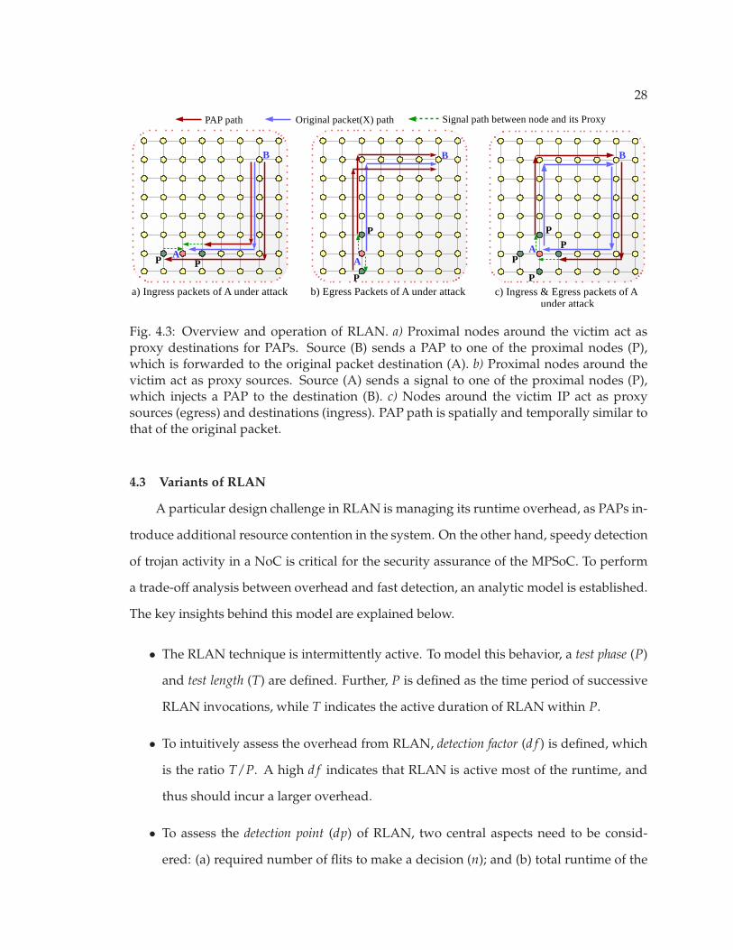
• Scenario 1–Attack on ingress packets: The trojan targets packets that are destined to
the victim node (A). Figure 4.3(a) illustrates the operation of RLAN, where the victim
node A’s ingress packets suffer from latency elongation. Consider that node B sends
a packet (X) to node A. A PAP is created and injected from B directed to one of the
nodes (P) proximal to X’s destination. When the PAP arrives at P, the SoC firmware
Fig. 4.2: Block diagram of SoC firmware with RLAN control. The SoC integrator augmentsthe RLAN control logic in the SoC Firmware. The SoC Firmware pads a timestamp to thedata before forwarding it to the NI for packetization.

27
identifies and re-injects it towards A. At A, the SoC firmware stores the arrival time
and compares it with the arrival time of X. Repeated deviations of packet arrival
times are flagged as abnormal network activities.
• Scenario 2–Attack on egress packets: The trojan targets packets originating from
the victim node (A). In this scenario, a PAP cannot be injected from the same source
as previously done, as all packets originating from the source are under attack (i.e,
delayed). To tackle this case, a node close to the source is used as a proxy. Figure
4.3(b) illustrates the operation, where the original source A sends a signal to any one
of the proximal nodes (P) every time it injects a packet (X). P interprets the signal and
injects a PAP to the same destination (B) as that of (X). At B, the SoC firmware com-
pares the arrival time and flags abnormal activity if repeated large deviations occur.
The solution complexity is higher, as the proximal nodes are unaware of neighboring
activities and need a signal from A. During the design of RLAN for this scenario, an-
other solution was deliberated upon where PAP is injected as a reply to an original
packet and their latency compared. But the solution is inaccurate due to variation in
sporadic network congestion as the path taken by the two packets is different both
spatially and temporally.
• Scenario 3–Attack on egress & ingress packets: In this scenario, the embedded tro-
jan attacks all packets originating from and destined to the victim node. This varia-
tion escalates solution complexity further as PAPs should neither originate nor travel
to the victim node directly. The first two solution variants are combined together to
tackle the complexity. Here, the SoC firmware is responsible for sending a signal to
generate an effective PAP, as well as, comparing arrival time of PAP. Figure 4.3(c) il-
lustrates the operation. Consider A as the victim node. For the egress packets, a PAP
is created at a node proximal to A and directed towards the destination. Whereas all
flits that are destined to A are first sent to the proximal node before being re-injected
towards A.
28
Fig. 4.3: Overview and operation of RLAN. a) Proximal nodes around the victim act asproxy destinations for PAPs. Source (B) sends a PAP to one of the proximal nodes (P),which is forwarded to the original packet destination (A). b) Proximal nodes around thevictim act as proxy sources. Source (A) sends a signal to one of the proximal nodes (P),which injects a PAP to the destination (B). c) Nodes around the victim IP act as proxysources (egress) and destinations (ingress). PAP path is spatially and temporally similar tothat of the original packet.
4.3 Variants of RLAN
A particular design challenge in RLAN is managing its runtime overhead, as PAPs in-
troduce additional resource contention in the system. On the other hand, speedy detection
of trojan activity in a NoC is critical for the security assurance of the MPSoC. To perform
a trade-off analysis between overhead and fast detection, an analytic model is established.
The key insights behind this model are explained below.
• The RLAN technique is intermittently active. To model this behavior, a test phase (P)
and test length (T) are defined. Further, P is defined as the time period of successive
RLAN invocations, while T indicates the active duration of RLAN within P.
• To intuitively assess the overhead from RLAN, detection factor (d f ) is defined, which
is the ratio T/P. A high d f indicates that RLAN is active most of the runtime, and
thus should incur a larger overhead.
• To assess the detection point (dp) of RLAN, two central aspects need to be consid-
ered: (a) required number of flits to make a decision (n); and (b) total runtime of the
29
program, modeled as m phases of length P. Both are application dependent, as n is
driven by the packet injection rate (i) of the program. dp is the percentage of total
runtime required to accurately identify the presence of the trojan.
d f =
T
P(4.1)
dp =
n
d f × i×
1
mP(4.2)
Equation 4.1 and Equation 4.2 presents the analytic model to explore the trade-off
between dp and d f . The first term of Equation 4.2 (for dp) denotes the total time for n
samples to be taken, while mP in the second term shows the total runtime of the program.
Ideally, the detection point should be low so that the embedded trojan can be quickly
detected.
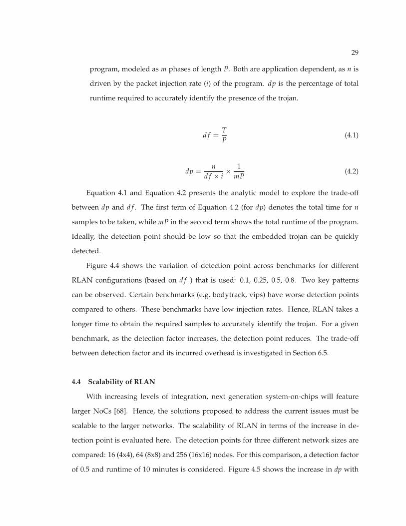
Figure 4.4 shows the variation of detection point across benchmarks for different
RLAN configurations (based on d f ) that is used: 0.1, 0.25, 0.5, 0.8. Two key patterns
can be observed. Certain benchmarks (e.g. bodytrack, vips) have worse detection points
compared to others. These benchmarks have low injection rates. Hence, RLAN takes a
longer time to obtain the required samples to accurately identify the trojan. For a given
benchmark, as the detection factor increases, the detection point reduces. The trade-off
between detection factor and its incurred overhead is investigated in Section 6.5.
4.4 Scalability of RLAN
With increasing levels of integration, next generation system-on-chips will feature
larger NoCs [68]. Hence, the solutions proposed to address the current issues must be
scalable to the larger networks. The scalability of RLAN in terms of the increase in de-
tection point is evaluated here. The detection points for three different network sizes are
compared: 16 (4x4), 64 (8x8) and 256 (16x16) nodes. For this comparison, a detection factor
of 0.5 and runtime of 10 minutes is considered. Figure 4.5 shows the increase in dp with

30
0
0.04
0.08
0.12
0.16
0.2
blacksch
oles
bodytrack
cannealferret
fluida
nimate
swaptions vip
sx264
avera
ge
Detection Point
0.1 0.25 0.5 0.8
0.36 0.29
df
Fig. 4.4: Detection point comparison for variants of RLAN. Variation of the detection point(dp) across benchmarks with n=100000. Detection point is evaluated for the 4 RLAN vari-ants represented by detection factors (df) of 0.1, 0.25, 0.5 and 0.8 (lower is better). Theruntime is considered to be 10 minutes.
increase in network size. Since each node in the network has to be assessed individually,
detection point increases as a factor of network size. It is observed that for a network con-
sisting of 256 nodes, the average detection point is at 8.2% of the total runtime compared
to 2% for 64 node NoC for the considered simulation parameters.
0
2
4
6
8
10
blacksch
oles
bodytrack
cannealferret
fluida
nimate
swaptions vip
sx264
avera
ge
Detection Point
4x4 8x8 16x16NoC Size18.72 15.03
Fig. 4.5: Scalability of RLAN. Variation of detection point for three NoC sizes: 4x4, 8x8 and16x16 for a detection factor (df) of 0.5 (lower is better).

31
4.5 Role of the SoC Firmware
The SoC firmware is an integral component of the proposed solution. Its role, listed
next, helps to explore the design trade-offs to successfully realize RLAN.
• The SoC integrator must decide parameters (test length and test phase) to limit over-
head. The SoC firmware must have provisions to hold the above test parameters and
inject PAPs at suitable periods.
• In all scenarios, proximal nodes serve as proxy nodes to mask the original source/
destination of the victim node. The SoC firmware must have the capability to inject,
identify and forward PAPs. At the same time, it must encode adequate information
to associate PAPs to their original counterparts, for arrival time comparison.
• Another prominent role is to accurately identify abnormal network activity. The SoC
firmware must only flag repeated deviations and be able to distinguish abnormal
activity from intermittent delays caused by sporadic congestion in the network.
These functions are implemented in a standard SoC OCP interface [69], and overhead
from its synthesized hardware is evaluated in Section 6.5.

32
Chapter 5
Methodology
This Chapter describes the simulation infrastructure that combines multiple tools to
obtain a rigorous and accurate analysis of the proposed trojan design and also the latency
monitoring system to identify the presence of such a trojan.
A meticulous cross-layer methodology is employed combining application induced
traffic simulation on a cycle-accurate NoC simulator with detailed circuit level analysis
from the synthesized hardware.
Architecture Layer: First, a traditional NoC without any security features is considered
as the baseline to evaluate the design cost. An open-source Stanford Verilog model of a
modern NoC router [66] is used for this evaluation. Further, the NoC routers are assumed
to be arranged as a 8x8 mesh topology (i.e, 64 nodes). The router has a 4 stage pipeline of
route computation, virtual channel allocation, switch allocation and switch traversal. The
RLAN technique is carefully modeled in Booksim 2.0 and real world application traces
(PARSEC benchmarks) from Netrace0.9 [65] are simulated. The network latency overhead
includes the effect of routing resource contention arising from the additional traffic intro-
duced through the proposed techniques.
Circuit Layer: The area/power overheads of the rNoC design is evaluated by augment-
ing the open-source Stanford Verilog model of a modern NoC router, and subsequently
synthesizing it using the Synopsys Design Compiler and a 45nm TSMC standard cell li-
brary. To assess the area/power overhead from the proposed techniques, the schemes are
implemented in a standard SoC OCP interface [69], and subsequently the design footprint
of the synthesized hardware is compared to the original footprint.

33
Chapter 6
Results
In this Chapter, the results on the efficacy of RLAN (Section 6.1) are discussed along
with the area, power and performance overheads of RLAN (Sections 6.4 and 6.5).
6.1 Efficacy
Network Latency Differential (NLD) is the difference in packet latency between a PAP
and its original counterpart. Figure 6.1 presents the CDF (cumulative distribution func-
tion) of PAPs with respect to NLD1. The figure shows the CDF for four cases: a no-attack
scenario (NA) and three attack scenarios (T1, T2 and T3 with 1, 2 and 3 cycle delay per
hop per flit belonging to victim node). Figure shows that in the absence of a bandwidth
denial attack (AVG NA cluster), a large percentile of PAPs will have small to negligible
NLDs. The NLD for no-attack scenario is a non-zero value as a PAP can be created only
after the SoC firmware processes the original data. Further, the created PAP must travel in
the same path as the original packet and contend for the same resources during this travel.
The attack cases on the other hand, have a noticeable NLD due to the delay inflicted by
the trojan at each hop. Hence, a clear distinction is seen between the CDF of no-attack case
and the attack cases.
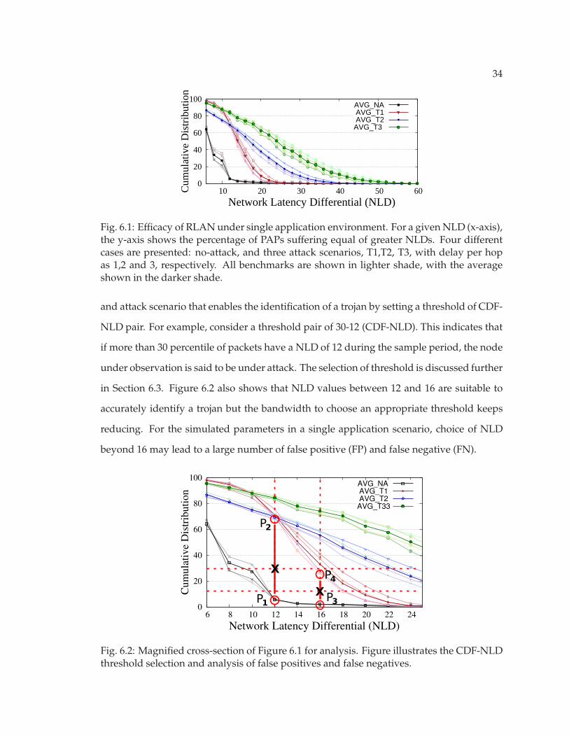
In Figure 6.2, it is observed that only 4% of packets have an NLD greater than 12
for the no-attack case (represented by point P1). However, during an attack, a significant
percent of PAPs are expected to have a higher NLD. This contrast in an attack scenario,
where more than 60% of packets have an NLD greater than the chosen NLD(12) is clearly
noticeable (represented by point P2). Hence, there is a clear separation between a no-attack
1To eliminate obvious noise, the presented data is truncated to a minimum NLD of 6.
34
0
20
40
60
80
100
10 20 30 40 50 60Cum
ulat
ive
Dis
trib
utio
n
Network Latency Differential (NLD)
AVG_NAAVG_T1AVG_T2
AVG_T3
Fig. 6.1: Efficacy of RLAN under single application environment. For a given NLD (x-axis),the y-axis shows the percentage of PAPs suffering equal of greater NLDs. Four differentcases are presented: no-attack, and three attack scenarios, T1,T2, T3, with delay per hopas 1,2 and 3, respectively. All benchmarks are shown in lighter shade, with the averageshown in the darker shade.
and attack scenario that enables the identification of a trojan by setting a threshold of CDF-
NLD pair. For example, consider a threshold pair of 30-12 (CDF-NLD). This indicates that
if more than 30 percentile of packets have a NLD of 12 during the sample period, the node
under observation is said to be under attack. The selection of threshold is discussed further
in Section 6.3. Figure 6.2 also shows that NLD values between 12 and 16 are suitable to
accurately identify a trojan but the bandwidth to choose an appropriate threshold keeps
reducing. For the simulated parameters in a single application scenario, choice of NLD
beyond 16 may lead to a large number of false positive (FP) and false negative (FN).
0
20
40
60
80
100
6 8 10 12 14 16 18 20 22 24
Cumulative Distribution
Network Latency Differential (NLD)
AVG_NAAVG_T1AVG_T2
AVG_T33
X
XP1
P2
P3
P4
Fig. 6.2: Magnified cross-section of Figure 6.1 for analysis. Figure illustrates the CDF-NLDthreshold selection and analysis of false positives and false negatives.

35
6.2 Multiple Application Environment
Given that an MPSoC may have multiple co-scheduled applications, it is imperative
to study the efficacy of the proposed schemes under such an environment. The proposed
technique is subjected to rigorous testing by superimposing heavy random traffic with an
injection rate of 0.25, on top of application induced traffic to simulate multiple applications
running simultaneously. Figure 6.3 shows the CDF plot for such a situation. There is an
observable amount of disturbance in the CDF compared to the results obtained for single
application environment. A very high injection rate of 0.25 was chosen to simulate the net-
work under significant load and carry out a worst case analysis to assess the performance
of the proposed technique. Even under this scenario, a less but clear distinction is noticed
between the attack and no-attack scenarios.
For example, in Figure 6.4 if the NLD of 12 is considered again, the percentage of
packets above the NLD in the no-attack case increases to 8% (denoted by point M1). In
contrast, for the three different attack scenarios, the corresponding percentile is still over
40% (denoted by point M2) for all benchmarks. It can be observed that the point M2 in
the figure is obtained for a specific benchmark that observes significant disturbance due
to co-scheduled applications and not the average of all benchmarks. This is done to limit
the FP and FN that can arise due to a wrong choice of threshold. Another noticeable factor
is that the NLD bandwidth for accurate trojan detection has reduced due to the increased
variance in packet latency caused by increased traffic in the NoC (now between 12 and 14).
0
20
40
60
80
100
10 20 30 40 50 60Cum
ulat
ive
Dis
trib
utio
n
Network Latency Differential (NLD)
AVG_NAAVG_T1AVG_T2AVG_T3
Fig. 6.3: Efficacy of RLAN under multi-program environment.

36
0
20
40
60
80
100
6 8 10 12 14 16 18 20 22 24
Cumulative Distribution
Network Latency Differential (NLD)
AVG_NAAVG_T1AVG_T2AVG_T3
X
M1
M2
M3
M4
X
Fig. 6.4: Magnified cross-section of Figure 6.3 for analysis. Figure illustrates the selectionof CDF-NLD threshold and analysis of false positives and false negatives.
6.3 CDF-NLD Threshold
To accurately identify the presence of a trojan, CDF-NLD threshold is carefully se-
lected to minimize the FP and FN. In Figure 6.2 (single application), point P1 denotes the
maximum percentile of packets with NLD-12 under no-attack and P2 denotes the per-
centile of packets having the same NLD (12) under an attack scenario. The difference in
CDF for these two scenarios is more than 50%. By choosing a CDF threshold of 30% (for
NLD 12), it is ensured that there are no FP or FN. Due to the clear distinction between
no-attack and attack scenario, the CDF threshold of 16% can also be used for a NLD of 16.
Hence, if more than 16% of packets have NLD greater than 16, the NoC’s availability is
said to be compromised by trojan activity.
Under the simultaneous application environment, it is seen that the contrast between
no-attack and attack scenarios reduces considerably. Increased network traffic and inter-
ference due to multiple applications induces sporadic delays in the network. If the same
threshold of 16% is retained for NLD of 16, it is observed that the false negative rate is
2.74% for ferret benchmark. Under this scenario, an attack having delay of 1 cycle per hop
may not be flagged as trojan activity. By re-evaluating the threshold to 23%(CDF) for NLD
of 12, zero FP and FN can be guaranteed. Figure 6.4 illustrates two threshold combina-
tions that can result in accurate identification of trojan activity. Points (M1, M2) and (M3,

37
M4) denote the extremes of CDF for NLD of 12 and 14 respectively.
Table 6.1 presents the false positive(FP) and false negative(FN) rates in both single
and multiple application environments. A CDF threshold of 30% is considered to assess
the FP and FN rates for four different NLD values: 10, 12 14 and 16. It is observed that
for NLD value of 12, the FP and FN are zero in both environments. NLD of 10 results in a
high false positive rate in the multiple application environment. Network congestion due
to multiple application will result in sporadic delays which are wrongly flagged as trojan
activity. On the other hand, selecting a high NLD threshold(16) can result in FN of 1.8%
and 6.2% in the two environments.
6.4 Performance Overhead
Figure 6.5 presents a comparative analysis of performance overhead across different
RLAN variants. The maximum overhead (10.48%) is seen in x264 when the detection factor
is 0.8. This configuration ensures high detectability as the test is active for a majority of
the application runtime. On an average, for d f = 0.8, the overhead incurred is 5.47%. The
variation in overheads for different benchmarks is due to the different injection rates of
the applications. At low injection rates, the relative impact of PAP induced congestion is
larger, resulting in higher RLAN overhead.
6.5 Area and Power
The overheads are evaluated by adding the security features in a standard SoC OCP
Table 6.1: False Positive (FP) and False Negative (FN) rates. FP and FN is shown withCDF threshold of 30% and four NLD values: 10, 12, 14 and 16 for both Single and multipleapplication environment.
NLDSingle Application Multiple Application
FP FN FP FN
10 2.13% 0% 17.88% 0%12 0% 0% 0% 0%14 0% 0% 0% 0.76%16 0% 1.83% 0% 6.21%

38
0
2
4
6
8
10
blackscholes
bodytrackcannealferret
fluidanimate vip
sx264
Average
Performance
Overhead(%)
0.1 0.25 0.5 0.8df
Fig. 6.5: Runtime Overhead of the RLAN technique. The performance overhead is evalu-ated for detection factors of 0.1, 0.25, 0.4 and 0.8.
interface [69]. RLAN incurs an area overhead of 12.73% due to the hardware for PAP
creation and latency comparison. Table 6.2 shows the power overhead for different config-
urations of RLAN. The RLAN circuit is active only for the length of the test and is power
gated for the rest of the application execution time. Hence, the detection factor plays a role
in deciding the power overhead incurred. For a detection factor of 0.8, the RLAN circuit is
active for 80% of the test phase and incurs a power overhead of 9.84%.
Table 6.2: Power Overhead due to RLAN configurations. The standard OCP interface isconsidered as the baseline.
df 0.1 0.25 0.5 0.8
Power Overhead 1.49% 3.28% 6.26% 9.84%
39
Chapter 7
Conclusion
This research explores a novel security threat stemming from the pervasive use of
3PIP NoC, where a rogue NoC can disrupt the perceived on-chip resource availability. The
following contributions are made to the domain of 3PIP NoC security.
• Established a potent and covert threat model in the on-chip communication infras-
tructure that can have a significant impact on application performance.
• Implemented a detailed design of a rogue NoC, analyzed its design footprint and
threat significance to demonstrate that a potent rNoC design is feasible with negligi-
ble footprint and scalable to larger networks.
• Designed a non-invasive technique (RLAN) to systematically monitor trustworthi-
ness of a 3PIP NoC during runtime and effectively counter the emerging security
threat.
• Analyzed the circuit-architectural impact of the proposed monitoring scheme under
realistic environments and showed that the proposed solution can provide security
assurance with modest overheads of 12.73% in area, 9.34% in power and 5.4% in
terms of network latency.
40
References
[1] C. Liu, J. Rajendran, C. Yang, and R. Karri, “Shielding heterogeneous mpsocs fromuntrustworthy 3pips through security-driven task scheduling,” in IEEE Symposiumon Defect and Fault-Tolerance in VLSI Systems (DFT), pp. 101–106, 2013.
[2] Knowledge@Wharton, “Collaborative innovation holds key to semicon-ductor industry growth,” http://knowledge.wharton.upenn.edu/article/
collaborative-innovation-holds-key-semiconductor-industry-growth/, 2013.
[3] M. Abramovici and P. Bradley, “Integrated circuit security: new threats and solu-tions,” in CSIIRW, p. 55, 2009.
[4] J. L. Funk, “Systems, components and modular design: the case of the us semicon-ductor industry,” IJTM, vol. 42, no. 4, pp. 387–413, 2008.
[5] G. Linden and D. Somaya, “Systemonachip integration in the semiconductor indus-try: industry structure and firm strategies,” Industrial and Corporate Change, vol. 12,no. 3, pp. 545–576, 2003.
[6] A. Waksman, M. Suozzo, and S. Sethumadhavan, “Fanci: identification of stealthymalicious logic using boolean functional analysis,” in ACM Conference on Computerand Communications Security (CCS), pp. 697–708, 2013.
[7] “Arteris leaps onto inc. 500 list of americas fastest-growing private companies,http://www.arteris.com/.”
[8] N. I. of Standards and Technology, An Introduction to Computer Security: The NISTHandbook.
[9] Y. Hoskote, S. R. Vangal, A. Singh, N. Borkar, and S. Borkar, “A 5-ghz mesh intercon-nect for a teraflops processor,” IEEE Micro, vol. 27, no. 5, pp. 51–61, 2007.
[10] D. Wentzlaff, P. Griffin, H. Hoffmann, L. Bao, B. Edwards, C. Ramey, M. Mattina, C.-C. Miao, J. F. Brown III, and A. Agarwal, “On-chip interconnection architecture of thetile processor,” IEEE/ACM International Symposium on Microarchitecture (MICRO), pp.15–31, 2007.
[11] P. Lotfi-Kamran, A.-M. Rahmani, M. Daneshtalab, A. Afzali-Kusha, and Z. Navabi,“Edxy - a low cost congestion-aware routing algorithm for network-on-chips,” Journalof Systems Architecture - Embedded Systems Design, vol. 56, no. 7, pp. 256–264, 2010.
[12] M. Ebrahimi, M. Daneshtalab, P. Liljeberg, J. Plosila, and H. Tenhunen, “Catra-congestion aware trapezoid-based routing algorithm for on-chip networks,” inIEEE/ACM Design Automation & Test in Europe (DATE), pp. 320–325, 2012.
41
[13] M. Li, Q.-A. Zeng, and W.-B. Jone, “Dyxy: a proximity congestion-aware deadlock-free dynamic routing method for network on chip,” in IEEE/ACM Design AutomationConference (DAC), pp. 849–852. ACM, 2006.
[14] Z. Shi, X. Zeng, and Z. Yu, “A scalable and reconfigurable fault-tolerant distributedrouting algorithm for nocs,” IEICE Transactions, vol. 94-D, no. 7, pp. 1386–1397, 2011.
[15] F. Chaix, D. Avresky, N.-E. Zergainoh, and M. Nicolaidis, “A fault-tolerant deadlock-free adaptive routing for on chip interconnects,” in IEEE/ACM Design Automation &Test in Europe (DATE), pp. 909–912, 2011.
[16] D. Fick, A. DeOrio, G. K. Chen, V. Bertacco, D. Sylvester, and D. Blaauw, “A highlyresilient routing algorithm for fault-tolerant nocs,” in IEEE/ACM Design Automation& Test in Europe (DATE), pp. 21–26, 2009.
[17] A. Alaghi, M. Sedghi, N. Karimi, M. Fathy, and Z. Navabi, “Reliable noc architectureutilizing a robust rerouting algorithm,” in Design Test Symposium (EWDTS), 2008 East-West, pp. 200–203, 2008.
[18] A. DeOrio, D. Fick, V. Bertacco, D. Sylvester, D. Blaauw, J. Hu, and G. K. Chen, “Areliable routing architecture and algorithm for nocs,” IEEE Transactions on Computer-Aided Design of Integrated Circuits and Systems (TCAD), vol. 31, no. 5, pp. 726–739, 2012.
[19] K. Hu, A. N. Nowroz, S. Reda, and F. Koushanfar, “High-sensitivity hardware trojandetection using multimodal characterization,” in IEEE/ACM Design Automation & Testin Europe (DATE), pp. 1271–1276, 2013.
[20] M. Li, A. Davoodi, and M. Tehranipoor, “A sensor-assisted self-authentication frame-work for hardware trojan detection,” in IEEE/ACM Design Automation & Test in Europe(DATE), pp. 1331–1336, 2012.
[21] S. Wei, K. Li, F. Koushanfar, and M. Potkonjak, “Provably complete hardware tro-jan detection using test point insertion,” in IEEE International Conference on Computer-Aided Design (ICCAD), pp. 569–576, 2012.
[22] S. Wei and M. Potkonjak, “The undetectable and unprovable hardware trojan horse,”in IEEE/ACM Design Automation Conference (DAC), p. 144, 2013.
[23] X. Zhang and M. Tehranipoor, “Ron: An on-chip ring oscillator network for hardwaretrojan detection,” in IEEE/ACM Design Automation & Test in Europe (DATE), pp. 1638–1643, 2011.
[24] M. Tehranipoor and F. Koushanfar, “A survey of hardware trojan taxonomy and de-tection,” IEEE Design and Test for Computers, vol. 27, no. 1, pp. 10–25, 2010.
[25] J. A. Roy, F. Koushanfar, and I. L. Markov, “Epic: Ending piracy of integrated circuits,”in IEEE/ACM Design Automation & Test in Europe (DATE), pp. 1069–1074, 2008.
[26] M. Potkonjak, S. Meguerdichian, A. Nahapetian, and S. Wei, “Differential publicphysically unclonable functions: Architecture and applications,” in IEEE/ACM De-sign Automation Conference (DAC), pp. 242–247, 2011.

42
[27] Y. Yao, M. Kim, J. Li, I. L. Markov, and F. Koushanfar, “Clockpuf: physical unclonablefunctions based on clock networks,” in IEEE/ACM Design Automation & Test in Europe(DATE), pp. 422–427, 2013.
[28] D. Forte and A. Srivastava, “On improving the uniqueness of silicon-based physicallyunclonable functions via optical proximity correction,” in IEEE/ACM Design Automa-tion Conference (DAC), pp. 96–105, 2012.
[29] R. Kumar and W. Burleson, “Litho-aware and low power design of a secure current-based physically unclonable function,” in ACM International Symposium on Low PowerElectronic Devices (ISLPED), pp. 402–407, 2013.
[30] R. Huang, D. Y. Deng, and G. E. Suh, “Orthrus: efficient software integrity protectionon multi-cores,” SIGARCH Comput. Archit. News, vol. 38, no. 1, pp. 371–384, Mar. 2010.
[31] M.-K. Yoon, S. Mohan, J. Choi, J.-E. Kim, and L. Sha, “Securecore: A multicore-basedintrusion detection architecture for real-time embedded systems,” in Real-Time andEmbedded Technology and Applications Symposium (RTAS), 2013 IEEE 19th, pp. 21–32,2013.
[32] D. Y. Deng, D. Lo, G. Malysa, S. Schneider, and G. E. Suh, “Flexible and efficientinstruction-grained run-time monitoring using on-chip reconfigurable fabric,” inIEEE/ACM International Symposium on Microarchitecture (MICRO), pp. 137–148. IEEEComputer Society, 2010.
[33] M. Ozsoy, D. Ponomarev, N. Abu-Ghazaleh, and T. Suri, “Sift: Low-complexityenergy-efficient information flow tracking on smt processors,” Computers, IEEE Trans-actions on, vol. PP, no. 99, pp. 1–1, 2012.
[34] X. Zhang, L. van Doorn, T. Jaeger, R. Perez, and R. Sailer, “Secure coprocessor-basedintrusion detection,” in Proceedings of the 10th workshop on ACM SIGOPS Europeanworkshop, pp. 239–242. ACM, 2002.
[35] B. Salamat, T. Jackson, A. Gal, and M. Franz, “Orchestra: intrusion detection usingparallel execution and monitoring of program variants in user-space,” in Proceedingsof the 4th ACM European conference on Computer systems, pp. 33–46. ACM, 2009.
[36] B. Salamat, T. Jackson, G. Wagner, C. Wimmer, and M. Franz, “Runtime defenseagainst code injection attacks using replicated execution,” Dependable and Secure Com-puting, IEEE Transactions on, vol. 8, no. 4, pp. 588–601, 2011.
[37] Q. Zeng, D. Wu, and P. Liu, “Cruiser: concurrent heap buffer overflow monitoringusing lock-free data structures,” SIGPLAN Not., vol. 46, no. 6, pp. 367–377, June 2011.
[38] A. Waksman and S. Sethumadhavan, “Tamper evident microprocessors,” inIEEE/ACM International Symposium on Security and Privacy, pp. 173–188, 2010.
[39] Y.-Y. Chen, P. A. Jamkhedkar, and R. B. Lee, “A software-hardware architecture forself-protecting data,” in ACM Conference on Computer and Communications Security(CCS), pp. 14–27, 2012.

43
[40] R. Elbaz, D. Champagne, C. H. Gebotys, R. B. Lee, N. R. Potlapally, and L. Torres,“Hardware mechanisms for memory authentication: A survey of existing techniquesand engines,” Transactions on Computational Science, vol. 4, pp. 1–22, 2009.
[41] S. Chen, J. Xu, N. Nakka, Z. Kalbarczyk, and R. K. Iyer, “Defeating memory corrup-tion attacks via pointer taintedness detection,” in IEEE Dependable Systems and Net-works (DSN), pp. 378–387, 2005.
[42] G. E. Suh, D. E. Clarke, B. Gassend, M. van Dijk, and S. Devadas, “Efficient memoryintegrity verification and encryption for secure processors,” in IEEE/ACM Interna-tional Symposium on Microarchitecture (MICRO), pp. 339–350, 2003.
[43] B. Gassend, G. E. Suh, D. E. Clarke, M. van Dijk, and S. Devadas, “Caches and hashtrees for efficient memory integrity verification,” in Proceedings of High PerformanceComputer Architecture (HPCA), pp. 295–306, 2003.
[44] J. Demme, R. Martin, A. Waksman, and S. Sethumadhavan, “Side-channel vulnerabil-ity factor: A metric for measuring information leakage,” in ISCA, pp. 106–117, 2012.
[45] T. E. Levin, J. S. Dwoskin, G. Bhaskara, T. D. Nguyen, P. C. Clark, R. B. Lee, C. E.Irvine, and T. Benzel, “Securing the dissemination of emergency response data withan integrated hardware-software architecture,” in TRUST, pp. 133–152, 2009.
[46] O. Gelbart, E. Leontie, B. Narahari, and R. Simha, “Architectural support for secur-ing application data in embedded systems,” in IEEE International Conference on Elec-tro/Information Technology (EIT), pp. 19–24, 2008.
[47] B. Rogers, C. Yan, S. Chhabra, M. Prvulovic, and Y. Solihin, “Single-level integrityand confidentiality protection for distributed shared memory multiprocessors,” inProceedings of High Performance Computer Architecture (HPCA), pp. 161–172, 2008.
[48] Y. Fei and Z. J. Shi, “Microarchitectural support for program code integrity monitor-ing in application-specific instruction set processors,” in IEEE/ACM Design Automa-tion & Test in Europe (DATE), pp. 815–820, 2007.
[49] A. Seshadri, M. Luk, A. Perrig, L. Doom, and P. Khosla, “Pioneer: Verifying codeintegrity and enforcing untampered code execution on legacy systems,” in MalwareDetection, ser. Advances in Information Security. Springer US, 2007, vol. 27, pp. 253–289.
[50] L. Fiorin, G. Palermo, S. Lukovic, V. Catalano, and C. Silvano, “Secure memory ac-cesses on networks-on-chip,” IEEE Transactions on Computers (TC), vol. 57, no. 9, pp.1216–1229, 2008.
[51] J.-P. Diguet, S. Evain, R. Vaslin, G. Gogniat, and E. Juin, “Noc-centric security of re-configurable soc,” in NOCS, pp. 223–232, 2007.
[52] C. H. Gebotys and R. J. Gebotys, “A framework for security on NoC technologies,” inIEEE Computer Society Annual Symposium on VLSI, pp. 113–117, 2003.
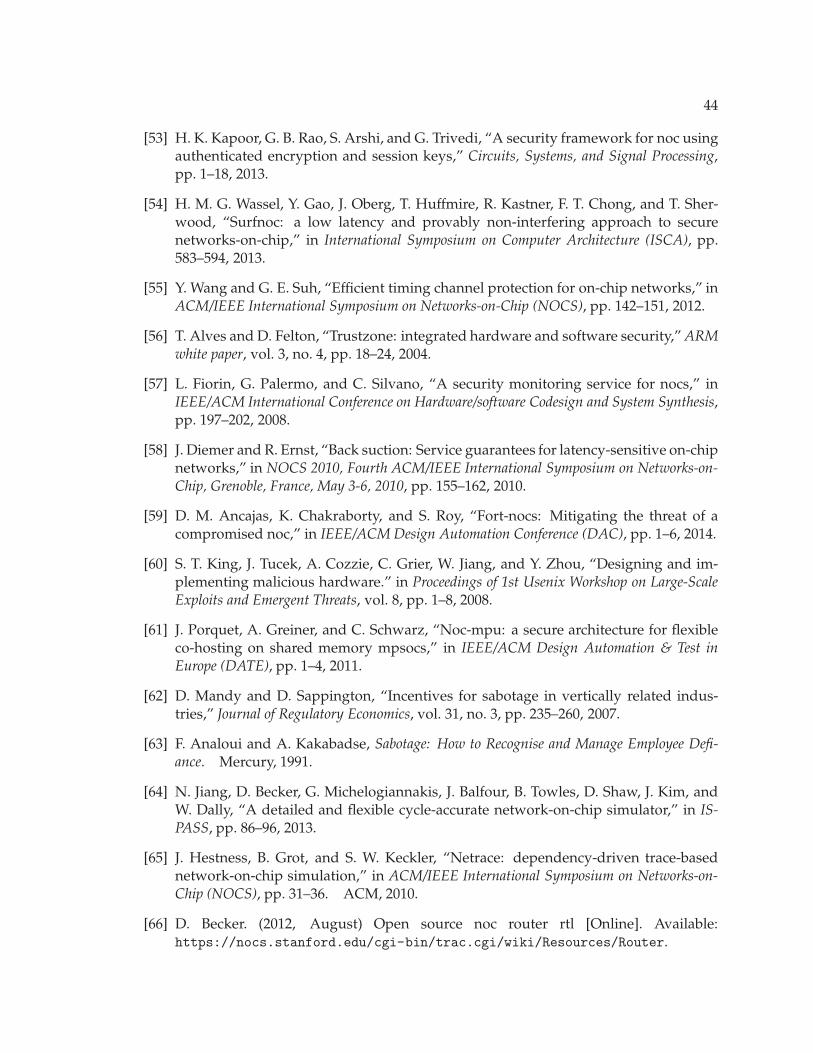
44
[53] H. K. Kapoor, G. B. Rao, S. Arshi, and G. Trivedi, “A security framework for noc usingauthenticated encryption and session keys,” Circuits, Systems, and Signal Processing,pp. 1–18, 2013.
[54] H. M. G. Wassel, Y. Gao, J. Oberg, T. Huffmire, R. Kastner, F. T. Chong, and T. Sher-wood, “Surfnoc: a low latency and provably non-interfering approach to securenetworks-on-chip,” in International Symposium on Computer Architecture (ISCA), pp.583–594, 2013.
[55] Y. Wang and G. E. Suh, “Efficient timing channel protection for on-chip networks,” inACM/IEEE International Symposium on Networks-on-Chip (NOCS), pp. 142–151, 2012.
[56] T. Alves and D. Felton, “Trustzone: integrated hardware and software security,” ARMwhite paper, vol. 3, no. 4, pp. 18–24, 2004.
[57] L. Fiorin, G. Palermo, and C. Silvano, “A security monitoring service for nocs,” inIEEE/ACM International Conference on Hardware/software Codesign and System Synthesis,pp. 197–202, 2008.
[58] J. Diemer and R. Ernst, “Back suction: Service guarantees for latency-sensitive on-chipnetworks,” in NOCS 2010, Fourth ACM/IEEE International Symposium on Networks-on-Chip, Grenoble, France, May 3-6, 2010, pp. 155–162, 2010.
[59] D. M. Ancajas, K. Chakraborty, and S. Roy, “Fort-nocs: Mitigating the threat of acompromised noc,” in IEEE/ACM Design Automation Conference (DAC), pp. 1–6, 2014.
[60] S. T. King, J. Tucek, A. Cozzie, C. Grier, W. Jiang, and Y. Zhou, “Designing and im-plementing malicious hardware.” in Proceedings of 1st Usenix Workshop on Large-ScaleExploits and Emergent Threats, vol. 8, pp. 1–8, 2008.
[61] J. Porquet, A. Greiner, and C. Schwarz, “Noc-mpu: a secure architecture for flexibleco-hosting on shared memory mpsocs,” in IEEE/ACM Design Automation & Test inEurope (DATE), pp. 1–4, 2011.
[62] D. Mandy and D. Sappington, “Incentives for sabotage in vertically related indus-tries,” Journal of Regulatory Economics, vol. 31, no. 3, pp. 235–260, 2007.
[63] F. Analoui and A. Kakabadse, Sabotage: How to Recognise and Manage Employee Defi-ance. Mercury, 1991.
[64] N. Jiang, D. Becker, G. Michelogiannakis, J. Balfour, B. Towles, D. Shaw, J. Kim, andW. Dally, “A detailed and flexible cycle-accurate network-on-chip simulator,” in IS-PASS, pp. 86–96, 2013.
[65] J. Hestness, B. Grot, and S. W. Keckler, “Netrace: dependency-driven trace-basednetwork-on-chip simulation,” in ACM/IEEE International Symposium on Networks-on-Chip (NOCS), pp. 31–36. ACM, 2010.
[66] D. Becker. (2012, August) Open source noc router rtl [Online]. Available:https://nocs.stanford.edu/cgi-bin/trac.cgi/wiki/Resources/Router.

45
[67] Gartner Inc., Semiconductor Design IP Revenue, Chip Infrastructure, Worldwide, 2012 and2013. Gartner Research, March 2014.
[68] B. Grot, J. Hestness, S. W. Keckler, and O. Mutlu, “Kilo-noc: a heterogeneous network-on-chip architecture for scalability and service guarantees,” in International Symposiumon Computer Architecture (ISCA), pp. 401–412, 2011.
[69] OCP International Partnership. (2009) Open Core Protocol Specification: Release 3.0[Online]. Available: www.ocpip.org.