Embed Size (px)
Citation preview

Wiadomo ci Konserwatorskie Conservation News 26/2009 147
NAUKA SCIENCE
Antonio Borri , Marco Corradi
Emanuela Speranzini , Andrea Giannantoni
Rubble stone masonry strengthened using “reticolatus” system
Mur z kamienia amanego wzmocniony za pomoc systemu „reticolatus”
1. Introduction
The consolidation and strengthening of masonry
walls that are subjected not only to their own
weight but also to possible dynamic stresses
constitute one of the most important reinforcement
works for achieving an adequate level of safety.
This is because poor quality in the mechanical
characteristics of the masonry (compressive strength,
shear strength, etc.), especially in old historic
buildings, has often been the cause of collapsing
or of serious damage, for example during seismic
events.
Another element that has a considerable
impact on the seismic behaviour of a masonry
construction is the connection between vertical
walls and between these and the horizontal
elements. If these connections are present and
effective, they can allow the structure to respond
adequately to dynamic stress by means of a “box-
-like” behaviour, without a loss of balance in the
individual sections. If these connections are
lacking, each individual element (a wall, floor
slab, etc.) will be more vulnerable, since it will be
free to collapse separately from the rest of the
construction.
The techniques used for restoring or reinforc-
ing masonry structures, such as the “scuci-cuci”
(patching) of the masonry, the repairing of cracks
by means of perforations reinforced with metal
bars, circling with strips of composite material, in-
jection into the masonry of cement grout or lime-
-based mixtures, reinforced plaster, etc., present
1. Wst p
Jednym z g ównych sposobów zapewnienia od-
powiedniego poziomu bezpiecze stwa budowlom
jest wzmocnienie ich cian murowanych, które nie
tylko obci one s w asnym ci arem, ale tak e
mog by nara one na obci enia dynamiczne.
S abe w asno ci mechaniczne (wytrzyma o
na ciskanie, wytrzyma o na cinanie, itd.) mu-
ru, szczególnie w starych budowlach zabytko-
wych, cz sto by y przyczyn ich zawalenia si lub
powa nego uszkodzenia, na przyk ad podczas trz -
sienia ziemi.
Inny czynnik maj cy du y wp yw na sejs-
miczne zachowanie si budowli murowanych to
po czenia pionowych cian ze sob i po czenia
cian z elementami poziomymi. Je li takie po-
czenia wyst puj i s skuteczne, budowla mo e
dzi ki pracy skrzynkowej odpowiednio zarea-
gowa na obci enia dynamiczne, nie trac c rów-
nowagi w swoich poszczególnych cz ciach. Je-
eli takich po cze nie ma, ka dy indywidualny
element ( ciana, p yta stropowa, itd.) b dzie bar-
dziej podatny na zawalenie si , niezale nie od
reszty budowli.
Techniki stosowane w celu odrestaurowania
lub wzmocnienia konstrukcji murowanych, takie
jak szpachlowanie (scuci-cuci), naprawa p k-
ni za pomoc otworów zbrojonych pr tami
metalowymi, wzmacniane ta mami z materia-
ów kompozytowych, wstrzykiwanie zaprawy
cementowej lub mieszanek bazuj cych na wap-
nie, tynk zbrojony itd., maj swoje ograniczenia.
Praca dopuszczona do druku po recenzjach Article accepted for publishing after reviews
Wiadomo ci Konserwatorskie Conservation News 26/2009 148
some limits and problems. This is especially true
in the case of irregular masonry in which it is
desired to keep the exterior facing unaltered.
The technique of the deep repointing of the
mortar joints that consists of stripping the joints in
the masonry by removing the original poor-quality
mortar and then repointing the joints with a good
quality mortar can be used when the fair-face
masonry must be kept. Its effectiveness, however,
is limited as regards the increase in the mechanical
properties of the masonry, especially if the walls
are very thick.
This paper describes a new reinforcement
system, called “reticolatus”, which is proposed
separately or in addition to other techniques (such
as injections) and it allows the reinforcement of
both regular and irregular masonry, with a limited
impact.
As is demonstrated in the experiments presented
below, it can make important contributions as
regards both horizontal stresses, such as those
caused by earthquakes, as well as static vertical
loads.
2. Description
of the reinforcement system
The reinforcement system consists of a continuous
mesh of tiny cords made of high strength steel,
which are inserted into the mortar joints and thus
embedded in the wall.
2.1. Materials used
The system is based on the use of following ma-
terials:
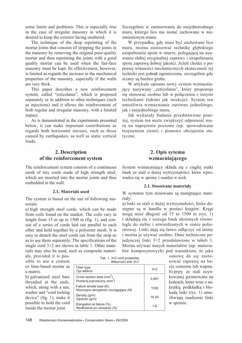
a) high strength steel cords, which can be made
from coils found on the market. The coils vary in
length from 15 m up to 1500 m (fig. 1), and con-
sist of a series of cords laid out parallel to each
other and held together by a polyester mesh. It is
easy to detach the steel cords out from the strip so
as to use them separately. The specifications of the
single cord 3×2 are shown in table 1. Other mate-
rials may also be used, such as composite materi-
als, provided it is pos-
sible to use a cement
or lime-based mortar as
a matrix.
b) galvanized steel bars
threaded at the ends,
which, along with a nut,
washer and “cord locking
device” (fig. 1), make it
possible to hold the cord
inside the mortar joint.
Szczególnie w zastosowaniu do niejednorodnego
muru, którego lico ma zosta zachowane w nie-
zmienionym stanie.
W przypadku, gdy musi by zachowane lico
muru, mo na zastosowa technik g bokiego
uzupe niania spoin w murze, polegaj c na usu-
waniu s abej oryginalnej zaprawy i uzupe nianiu
spoin zapraw dobrej jako ci. Je eli chodzi o po-
praw w asno ci mechanicznych skuteczno tej
techniki jest jednak ograniczona, szczególnie gdy
ciany s bardzo grube.
W artykule opisano nowy system wzmacnia-
j cy nazywany „reticolatus”, który proponuje
si stosowa osobno lub w po czeniu z innymi
technikami (takimi jak iniekcje). System ten
umo liwia wzmacnianie zarówno jednolitego,
jak i niejednolitego muru.
Jak wykaza y badania przedstawione poni-
ej, system ten mo e zwi kszy odporno mu-
ru na napr enia poziome (np. spowodowane
trz sieniem ziemi) i pionowe obci enia sta-
tyczne.
2. Opis sytemu
wzmacniaj cego
System wzmacniaj cy sk ada si z ci g ej siatki
linek ze stali o du ej wytrzyma o ci, które wpro-
wadza si w spoiny i osadza w nich.
2.1. Stosowane materia y
W systemie tym stosowane s nast puj ce mate-
ria y:
a) linki ze stali o du ej wytrzyma o ci, które do-
st pne s w handlu w postaci kr gów. Kr gi
mog mie d ugo od 15 to 1500 m (rys. 1)
i sk adaj si z szeregu linek u o onych równo-
legle do siebie i utwierdzonych w siatce polie-
strowej. Linki daj si atwo od czy od ta my
i mo na je u ywa osobno. Dane techniczne po-
jedynczej linki 3×2 przedstawiono w tabeli 1.
Mo na u ywa innych materia ów (np. materia-
ów kompozytowych) pod warunkiem, e jako
osnow da si zasto-
sowa zapraw na ba-
zie cementu lub wapna.
b) pr ty ze stali ocyn-
kowanej gwintowane na
ko cach, które wraz z na-
kr tk , podk adk i blo-
kad linki (rys. 1) umo-
liwiaj osadzenie linki
w spoinie.
Tab. 1. 3×2 cord properties W asno ci linki 3×2
Fiber type Typ w ókna
3×2
Cross section area (mm2)
Przekrój poprzeczny (mm2)
0.481
Failure tensile load (N) Niszcz ce obci enie rozci gaj ce (N)
1539
Density (g/m) G sto (g/m)
18.45
Elongation at failure (%) Wyd u enie po zerwaniu (%)
1.6
Wiadomo ci Konserwatorskie Conservation News 26/2009 149
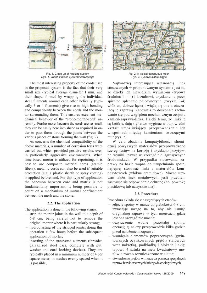
The most interesting property of the cords used
in the proposed system is the fact that their very
small size (typical average diameter 1 mm) and
their shape, formed by wrapping the individual
steel filaments around each other helically (typi-
cally 3 or 4 filaments) give rise to high bonding
and compatibility between the cords and the mor-
tar surrounding them. This ensures excellent me-
chanical behavior of the “stone-mortar-cord” as-
sembly. Furthermore, because the cords are so small,
they can be easily bent into shape as required in or-
der to pass them through the joints between the
various pieces of stone forming the wall (fig. 2).
As concerns the chemical compatibility of the
above materials, a number of corrosion tests were
carried out which provided positive results, even
in particularly aggressive environments. When
lime-based mortar is utilized for repointing, it is
best to use composite material cords (aramid
fibers); metallic cords can also be used if suitable
protection (e.g. a plastic sheath or spray coating)
is applied beforehand. For this type of application
the adhesion between cord and matrix is not
fundamentally important, it being possible to
count on a mechanism of mutual confinement
between the mesh and the stone.
2.2. The application
The application is done in the following stages:
– strip the mortar joints in the wall to a depth of
6-8 cm, being careful not to remove the
original mortar where it is particularly strong;
– hydroblasting of the stripped joints, doing this
operation a few hours before the subsequent
application of mortar;
– inserting of the transverse elements (threaded
galvanized steel bars, complete with nut,
washer and cord locking device). They are
typically placed in a minimum number of 4 per
square meter, in meshes evenly spaced when it
is possible;
Najbardziej interesuj c w asno ci linek
stosowanych w proponowanym systemie jest to,
e dzi ki ich niewielkim wymiarom (typowa
rednica 1 mm) i kszta towi, uzyskanemu przez
spiralne splecenie pojedynczych (zwykle 3-4)
w ókien, dobrze cz i wi si one z otacza-
j c je zapraw . Zapewnia to doskona e zacho-
wanie si pod wzgl dem mechanicznym zespo u
kamie -zaprawa-linka. Dzi ki temu, e linki te
s krótkie, daj si atwo wygina w odpowiedni
kszta t umo liwiaj cy przeprowadzenie ich
w spoinach mi dzy kamieniami tworz cymi
mur (rys. 2).
W celu zbadania kompatybilno ci chemi-
cznej powy szych materia ów przeprowadzono
szereg testów na korozj i uzyskano pozytyw-
ne wyniki, nawet w szczególnie agresywnych
rodowiskach. W przypadku stosowania za-
prawy na bazie wapna do uzupe niania spoin,
najlepiej stosowa linki z materia ów kom-
pozytowych (w ókna aramidowe). Mo na u y-
wa tak e linek metalowych, je li przedtem
zastosuje si odpowiedni ochron (np. pow ok
plastikow lub natryskiwan ).
2.2. Procedura
Procedura sk ada si z nast puj cych etapów:
– zdj cie spoiny w murze do g boko ci 6-8 cm,
zwracaj c uwag na to, aby nie usun
oryginalnej zaprawy w tych miejscach, gdzie
jest ona szczególnie mocna;
– oczyszczenie wodne pozosta ej spoiny;
operacj t nale y przeprowadzi kilka godzin
przed na o eniem zaprawy;
– wsuni cie elementów poprzecznych (gwin-
towanych ocynkowanych pr tów stalowych
wraz nakr tk , podk adk i blokad linki);
typowo 4 sztuki na metr kwadratowy mo-
liwie równo rozmieszczone w siatce;
– utwierdzenie pr tów w murze za pomoc specjalnych
zapraw bezskurczowych lub ywic epoksydowych;
Fig. 1. Close-up of hooking system
Rys. 1. Widok z bliska systemu kotwi cego Fig. 2. A typical continuous mesh
Rys. 2. Typowa siatka ci g a

Wiadomo ci Konserwatorskie Conservation News 26/2009 150
– fixing of the bars to the wall using specific
non-shrink mortars or epoxy resins;
– first repointing with mortar;
– insertion of the UHTSS cords into the stripped
joints, passing them through the cord locking
devices, proceeding horizontally or vertically
across the entire facing being reinforced. If the
individual cords are not long enough, they can
be joined with resin or simply overlapped with
each other by about 20 cm;
– if considered necessary additional cords can be
applied diagonally in both directions;
– tightening of the nuts to lightly tension the
cords;
– second repointing of the mortar in the joints,
completely covering both the cords and the
heads of the eyebolts or bars;
– aesthetic finishing of the joints by brushing them
with a metal brush.
From a mechanical perspective, the benefits
that can be expected are: improved mechanical
characteristics (both compression and shear strength,
as well as flexural strength for loads both in and
out of the plane of the masonry panel), the ability
to extensively connect the vertical walls to one
another and the vertical walls to the horizontal
elements, the possibility of giving the masonry
tensile strength, transverse connections between
the facings of the masonry.
The system proposed can be used either locally,
for example on single wall panels in existing
structures (boundary walls, city walls, etc.), or
overall, i.e. as a reinforcement system for a masonry
construction for improving the overall behavior of
entire buildings, especially as regards structural
behavior during earthquakes.
3. Experiments
In order to investigate the effectiveness of the
proposed reinforcement technique, three different
series of tests were planned: compression tests
using two flat jacks, diagonal tests and flexural
tests.
3.1. Compression tests
The compression tests were carried out on the city
walls of Trevi (Perugia – Italy). Masonry portions
of walls about 50 cm thick were tested by being
subjected to compression on a single vertical axis
using two flat jacks. During the test the values of
the applied pressure and the deflection of the
masonry were recorded at each load step. These
values were processed to give the stress-strain
diagrams (fig. 3), from which the compression
– pierwsze uzupe nienie spoiny zapraw ;
– wprowadzenie linek ze stali o du ej wytrzy-
ma o ci w szczelin po usuni tej spoinie
i przewleczenie ich przez bloki linki, id c po-
ziomo lub pionowo, w ca ym wzmacnianym
licu; je eli pojedyncze linki nie s wystar-
czaj co d ugie, mo na je po czy za pomoc
ywicy lub po prostu zastosowa 20 cm d ug
zak adk ;
– w razie potrzeby mo na zastosowa dodatkowe
linki po przek tnej w obu kierunkach;
– dokr cenie nakr tek w celu lekkiego napi cia
linek;
– drugie uzupe nienie zaprawy w spoinach, tak
aby ca kowicie pokry linki, by rub oczko-
wych i pr ty;
– wyko czenie estetyczne spoin przez oczysz-
czenie ich szczotk drucian .
Z punktu widzenia w asno ci mechanicz-
nych mo na oczekiwa nast puj cych korzy ci:
lepsze charakterystyki mechaniczne (wytrzyma-
o na ciskanie, cinanie i zginanie w przypad-
ku obci e dzia aj cych zarówno w p aszczy-
nie, jak i poza p aszczyzn p yty muru), mo-
liwo po czenia w szerokim zakresie cian
pionowych ze sob oraz cian pionowych z ele-
mentami poziomymi, mo liwo nadania wy-
trzyma o ci na rozci ganie poprzecznym po -
czeniom mi dzy licami muru.
Proponowany system mo na stosowa lo-
kalnie, np. na pojedynczych p ytach ciennych
w istniej cych konstrukcjach (mury graniczne,
mury miasta, itd.) lub globalnie, tzn. jako sy-
stem wzmacniaj cy ca e konstrukcje murowane
w celu poprawy ich pracy, szczególnie podczas
trz sie ziemi.
3. Próby
W celu zbadania skuteczno ci proponowanej tech-
niki wzmacniania, zaplanowano i przeprowadzono
trzy ró ne serie prób: próby ciskania z u yciem
dwóch podno ników p askich, próby cinania
i próby zginania.
3.1. Próby ciskania
Próby ciskania przeprowadzono na murach
miejskich Trevi (Perugia, W ochy). Bloki mu-
ru o grubo ci 50 cm poddawano próbie ciska-
nia w jednej osi pionowej za pomoc dwóch
podno ników p askich. Podczas próby w ka -
dym kroku obci ania rejestrowano warto ci
nacisku i ugi cia muru. Na podstawie tych war-
to ci sporz dzano wykresy rozci gania (rys. 3)
i obliczano wytrzyma o na ciskanie oraz

Wiadomo ci Konserwatorskie Conservation News 26/2009 151
resistance and Young’s modulus calculated at
33% of the maximum stress were determined.
The results shown in table 2 and in figure 3,
regard: the unreinforced masonry (URM), the
deep repointed masonry (REP) and the masonry
reinforced with the reticolatus technique (SRE).
Upon analysis of the results, it can be stated that
the reticolatus technique is able to increase
significantly the compressive strength max of the
masonry: a mean value of 1.29 MPa was measured,
corresponding to an increase of compression
strength of 116% compared to the unreinforced
panels ( max = 0.595 MPa). Furthermore, the mean
increase of the masonry reinforced with repointing
alone ( max = 0.834 MPa) is about 40% compared
to unreinforced panel.
As concerns the failure mechanism, it was seen
that a series of vertical cracks formed between the
two flat jacks. Furthermore, there was no substantial
differentiation of the type of failure between the
unreinforced masonry, the repointed masonry and
the masonry reinforced with metal fibers. Whereas
in the cases of the unreinforced masonry and of
the repointed joints the failure occurred with a small
number of fairly large vertical cracks, in the case
of reticolatus reinforced masonry a larger number
of smaller vertical cracks occurred, indicating
an improvement in the mechanical behavior of
the masonry due to a probable decrease in the
concentration of the maximum stresses within
the masonry.
3.2. Shear tests
The diagonal compression test defined by the
ASTM E 519-81 Standard was designed in order
to evaluate the effectiveness of the reinforcement
as regards shear stress. The tests were performed
on site on three stone masonry panels cut from
a 17th
century building in Pale, near Foligno
(Perugia – Italy).
The panels, having a thickness of 53 cm and
modu Younga przy 33% maksymalnego na-
pr enia.
Wyniki przedstawione w tabeli 2 i na rysunku 3
dotycz muru niewzmocnionego (URM), muru
z g boko uzupe nionymi spoinami (REP) i muru
wzmocnionego przy zastosowaniu techniki retico-
latus (SRE). Na podstawie analizy tych wyników
mo na stwierdzi , e stosuj c technik reticolatus
mo na znacznie zwi kszy wytrzyma o na cis-
kanie max muru – rednia warto zmierzona 1,29
MPa odpowiada a wytrzyma o ci na ciskanie rz -
du 116% w stosunku do p yt niewzmocnionych
( max = 0,595 MPa). Ponadto, redni wzrost wy-
trzyma o ci muru wzmocnionego tylko poprzez
uzupe nienie spoin ( max = 0,834 MPa) wynosi
oko o 40% w stosunku do p yty niewzmocnionej.
Je eli chodzi o mechanizm zniszczenia, to poja-
wi o si kilka pionowych p kni w murze mi dzy
dwoma podno nikami p askim. Ponadto nie zaobser-
wowano istotnych ró nic w typie zniszczenia mi dzy
murem niewzmocnionym, murem z uzupe nionymi
spoinami i murem wzmocnionym za pomoc w ókien
metalowych. W przypadku muru niewzmocnionego
i muru z uzupe nionymi spoinami zniszczeniu towa-
rzyszy o powstanie kilku stosunkowo du ych p kni
a w przypadku muru wzmocnionego za pomoc sys-
temu reticolatus wyst pi a wi ksza liczba drobnych
sp ka , co wskazuje na popraw pracy mechanicz-
nej tego muru, prawdopodobnie dzi ki zmniejszeniu
si koncentracji napr e maksymalnych w tym
murze.
3.2. Próby cinania
Próby cinania przeprowadzono zgodnie z norm
ASTM E 519-81 w celu oceny skuteczno ci pro-
ponowanego wzmocnienia w przypadku napr e
cinaj cych. Próby przeprowadzono na miejscu na
trzech p ytach murowych wyci tych z siedem-
nastowiecznego budynku w Pale ko o Foligno
(Perugia, W ochy).
P yty mia y grubo 53 cm i zbudowane by y
0
2
4
6
8
10
12
14
0,000 0,002 0,004 0,006 0,008 0,010
Normal strain
Ve
rtic
al str
ess
[kg
/cm
2]
SRE 05
SRE 04
REP 03
URM 01
REP 02
Tab. 2. Results of the tests with double flat jacks Wyniki prób ciskania za pomoc dwóch podno ników p askich
Max compression stress
max (MPa) Maksymalne obci enie ciskaj ce max (MPa)
Young’s modulus E1/3 (MPa) Modu Younga E1/3 (MPa)
URM 01 0.595 480
REP 02 0.807 393
REP 03 0.857 512
SRE 04 1.261 486
SRE 05 1.312 2416
Fig. 3. Diagram ( - ) resulting from the tests with double flat jacksRys. 3. Wykres ( - ) sporz dzony na podstawie wyników próby
ciskania (napr enie pionowe, odkszta cenie normalne)
Wiadomo ci Konserwatorskie Conservation News 26/2009 152
consisting of very roughly hewn stone (travertine
and compact limestones) and lime-based mortar
with weak mechanical properties, were consisted
of two weakly toothed facings without cross
blocks.
The panels were cut to a size of 120×120 cm,
and a series of metal beams were then applied
at the two edges of one of the two diagonals of
the panel, connected by bars. A jack was applied
at one of the edges in order to stress the panel
until it failed along one of the two diagonals.
The diagonals on both faces of the panel were
instrumented with two inductive displacement
transducers. During testing the load applied and
the variation in the length of the diagonals were
recorded.
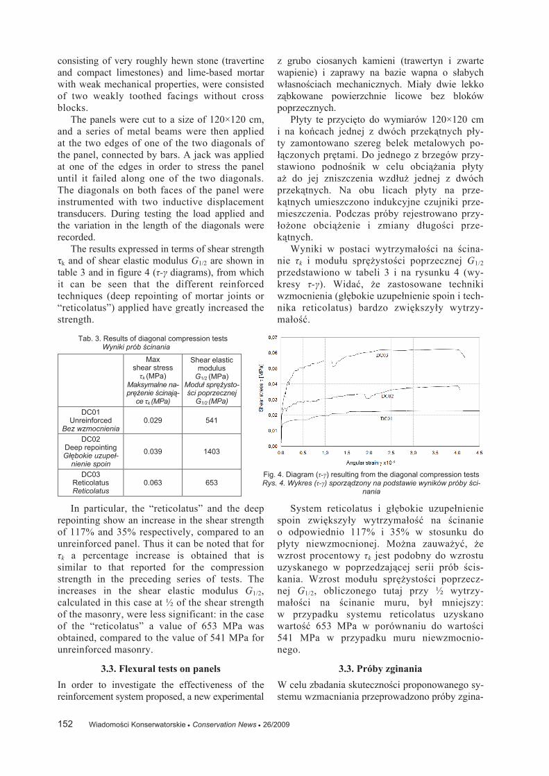
The results expressed in terms of shear strength
k and of shear elastic modulus G1/2 are shown in
table 3 and in figure 4 ( - diagrams), from which
it can be seen that the different reinforced
techniques (deep repointing of mortar joints or
“reticolatus”) applied have greatly increased the
strength.
In particular, the “reticolatus” and the deep
repointing show an increase in the shear strength
of 117% and 35% respectively, compared to an
unreinforced panel. Thus it can be noted that for
k a percentage increase is obtained that is
similar to that reported for the compression
strength in the preceding series of tests. The
increases in the shear elastic modulus G1/2,
calculated in this case at ½ of the shear strength
of the masonry, were less significant: in the case
of the “reticolatus” a value of 653 MPa was
obtained, compared to the value of 541 MPa for
unreinforced masonry.
3.3. Flexural tests on panels
In order to investigate the effectiveness of the
reinforcement system proposed, a new experimental
z grubo ciosanych kamieni (trawertyn i zwarte
wapienie) i zaprawy na bazie wapna o s abych
w asno ciach mechanicznych. Mia y dwie lekko
z bkowane powierzchnie licowe bez bloków
poprzecznych.
P yty te przyci to do wymiarów 120×120 cm
i na ko cach jednej z dwóch przek tnych p y-
ty zamontowano szereg belek metalowych po-
czonych pr tami. Do jednego z brzegów przy-
stawiono podno nik w celu obci ania p yty
a do jej zniszczenia wzd u jednej z dwóch
przek tnych. Na obu licach p yty na prze-
k tnych umieszczono indukcyjne czujniki prze-
mieszczenia. Podczas próby rejestrowano przy-
o one obci enie i zmiany d ugo ci prze-
k tnych.
Wyniki w postaci wytrzyma o ci na cina-
nie k i modu u spr ysto ci poprzecznej G1/2
przedstawiono w tabeli 3 i na rysunku 4 (wy-
kresy - ). Wida , e zastosowane techniki
wzmocnienia (g bokie uzupe nienie spoin i tech-
nika reticolatus) bardzo zwi kszy y wytrzy-
ma o .
System reticolatus i g bokie uzupe nienie
spoin zwi kszy y wytrzyma o na cinanie
o odpowiednio 117% i 35% w stosunku do
p yty niewzmocnionej. Mo na zauwa y , e
wzrost procentowy k jest podobny do wzrostu
uzyskanego w poprzedzaj cej serii prób cis-
kania. Wzrost modu u spr ysto ci poprzecz-
nej G1/2, obliczonego tutaj przy ½ wytrzy-
ma o ci na cinanie muru, by mniejszy:
w przypadku systemu reticolatus uzyskano
warto 653 MPa w porównaniu do warto ci
541 MPa w przypadku muru niewzmocnio-
nego.
3.3. Próby zginania
W celu zbadania skuteczno ci proponowanego sy-
stemu wzmacniania przeprowadzono próby zgina-
Tab. 3. Results of diagonal compression tests Wyniki prób cinania
Max shear stress
k (MPa) Maksymalne na-pr enie cinaj -
ce k (MPa)
Shear elasticmodulus
G1/2 (MPa) Modu spr ysto-
ci poprzecznej G1/2 (MPa)
DC01 Unreinforced
Bez wzmocnienia 0.029 541
DC02 Deep repointing G bokie uzupe -
nienie spoin
0.039 1403
DC03 Reticolatus Reticolatus
0.063 653
Fig. 4. Diagram ( - ) resulting from the diagonal compression tests Rys. 4. Wykres ( - ) sporz dzony na podstawie wyników próby ci-
nania

Wiadomo ci Konserwatorskie Conservation News 26/2009 153
test was conducted, building two rubble stone wall
panels reinforced using the “reticolatus” technique.
The two panels were then rotated and placed
horizontally, thus subjecting them to a particularly
severe flexural test, given the great weight of this
wall type.
The panels were built with rough-hewn limestone
rubble coming from the demolition of existing walls
and cement-lime mortar with modest mechanical
properties. The panels are made up of two facings,
one (panel 1) without any headers, and the other
(panel 2) weakly toothed. Once they had set, the
two panels were reinforced with the “reticolatus”
technique, using the same 3×2 cords manufactured
by Hardwire LLC used previously, according to
the stages previous described.
In the first panel, built to investigate the
flexural behavior (dimensions: 50 × 268 × 100 cm),
in the longitudinal direction 24 cords/meter were
applied to the intrados and 12 cords/meter to the
extrados, whereas in the transversal direction 24
cords/meter were inserted, for a total of 324 cords
applied (fig. 5).
The second panel, built to investigate the shear
behavior (40 × 180 × 198 cm), was reinforced in
a manner similar to the first panel, again with 12
cords/m on both faces and in both directions, and
integrating the face that will be on the inside with
an equal number of cords, thus obtaining 24
cords/meter in the two directions on the intrados
and 12 cords/meter in the two directions on the
extrados, for a total of 175 cords applied (fig. 6).
Repointing was done on both panels with
cement-lime mortar with modest mechanical
properties, with an average depth of about 7 cm.
The cords were inserted at a depth of 3-4 cm.
The first panel was placed on a horizontal plane,
supporting it at the ends. The four-point bending
nia na dwóch p ytach zbudowanych z kamienia
amanego, wzmocnionych za pomoc techniki re-
ticolatus.
P yty te obrócono i u o ono poziomo, poddaj c
je w ten sposób ci kiej (bior c pod uwag wielki
ci ar p yty tego rodzaju) próbie zginania.
P yty wykonano z grubo ciosanych kamieni
wapiennych (pochodz cych z rozbiórki istnie-
j cych murów) stosuj c zapraw cementowo-
wapnow o s abych w asno ciach mechani-
cznych. P yty mia y dwa lica. Jedna p yta (p yta
nr 1) by a bez jakichkolwiek g ówek a druga
p yta (p yta nr 2) by a lekko z bkowana. Po ich
wykonaniu p yty wzmocniono stosuj c technik
reticolatus i takie same linki 3×2 (wyproduko-
wane przez firm Hardwire LLC) i etapy jak
poprzednio.
W pierwszej p ycie (50 × 268 × 100 cm) w kie-
runku wzd u nym zastosowano 12 linek na metr
na podniebieniu i 12 linek na metr na grzbiecie,
a w kierunku poprzecznym 24 linki na metr.
W sumie zastosowano 324 linki (rys. 5).
Drug p yt (40 × 180 × 198 cm) wzmocniono
w podobny sposób jak pierwsz , stosuj c 24 lin-
ki/metr w obu kierunkach na podniebieniu i 12 li-
nek/metr w obu kierunkach na grzbiecie. W sumie
zastosowano 175 linek (rys. 6).
Spoiny w obu p ytach uzupe niono zapraw
cementowo-wapnow o s abych w asno ciach me-
chanicznych, do redniej g boko ci oko o 7 cm.
Linki wsuni to na g boko 3-4 cm.
Pierwsz p yt umieszczono w p aszczy nie
poziomej, podpieraj c j na ko cach. Podda-
no j próbie czteropunktowego zginania przy
rozpi to ci 208 cm i obci eniach oddalonych
38 cm od siebie (rys. 7). P yta by a obci ona
ci arem w asnym (oszacowanym na 2200 kg/m3)
Fig. 5. Panel 1: front and side views
Rys. 5. P yta 1: widok z przodu i z boku Fig. 6. The second panel subjected to flexural tests
Rys. 6. Druga p yta poddana próbie zginania

Wiadomo ci Konserwatorskie Conservation News 26/2009 154
test was done, with a span of 208 cm and with the
loads spaced 38 cm apart (fig. 7). The panel was
stressed by its own weight (calculable at 2200 Kg/m3)
as well as by the application of a load increased by
increments of 150 kg, distributed among the two
loading devices. The displacement was measured
by six centesimal comparators placed on both sides
of the panel, at midpoint, ¼ and ¾ of the span.
The panel reached a critical situation with a load
of about 600 kg, corresponding to a maximum
flexural moment of 255 kgm, which are added to
the 595 kgm deriving from its own weight.
As regards the panel failure mode, various
observations can be made. Some cracks parallel to
the supports opened in the tension zone, starting
with the third load step (450 kg), and these cracks
widened progressively up to the 650 kg load,
when, due to the deformation of the intrados,
some pieces of the intrados contained inside the
mesh of the “reticolatus” fell by gravity, and then
the masonry itself crumbled apart (fig. 8).
In comparison with a situation of an evenly
distributed load equivalent to that applied in
the case being examined, the panel failed with
a uniform load (inclusive of its own weight) of
1610 kg/m.
The second panel (40 × 180 × 198 cm) was
also subjected to a four-point bending flexural
test. In this case the panel was significantly
shorter and wider than the first panel. The load,
almost entirely concentrated in the middle, has
a punching effect on the panel that mobilizes
mainly the out-of-plane shear resistance.
The panel was tested over a span of 124 cm
(along the 180 cm side), and the load was applied
by means of two HEA metal beams spaced 35 cm
apart, with loads increasing by steps of 100 kg
(fig. 9).
The test results seem especially significant for
the purposes of demonstrating the effectiveness of
oraz przy o onym obci eniem zwi kszanym
stosuj c przyrosty wielko ci 150 kg, roz o o-
nym mi dzy dwoma urz dzeniami obci aj -
cymi. Przemieszczenie mierzono sze cioma
komparatorami umieszczonymi po obu stronach
p yty w rodku rozpi to ci, w ¼ rozpi to ci i ¾
rozpi to ci. P yta osi gn a stan krytyczny pod
obci eniem oko o 600 kg, odpowiadaj cym ma-
ksymalnemu momentowi zginaj cemu 255 kgm,
dodanym do 595 kgm pochodz cych od ci aru
w asnego.
Je eli chodzi o symptomy zniszczenia p yty
to zaobserwowano co nast puje: kilka rys rów-
noleg ych do podpór pojawi o si w strefie roz-
ci gania, poczynaj c od trzeciego kroku obci -
ania (450 kg) i rysy te rozszerza y si stop-
niowo do osi gni cia obci enia 650 kg, kiedy
to na skutek odkszta cenia podniebienia kilka
fragmentów podniebienia uj tych w siatce reti-
colatus wypad o pod w asnym ci arem, po czym
mur rozpad si (rys. 8).
W kategoriach równomiernie roz o onego ob-
ci enia, równowa nego obci eniu zastosowane-
mu w próbie opisanej powy ej, p yta uleg a zni-
szczeniu pod równomiernym obci eniem (wlicza-
j c w to jej ci ar w asny) wynosz cym 1610 kg/m.
Druga p yta (40 × 180 × 198 cm) równie zo-
sta a poddana próbie zginania czteropunktowego.
W tym przypadku p yta by a znacznie krótsza i
szersza ni pierwsza p yta. Obci enie, prawie
ca kowicie skoncentrowane po rodku oddzia ywa-
o przebijaj co na p yt , mobilizuj c g ównie nie-
p aski opór cinania.
P yta ta by a poddana próbie na rozpi to ci
124 cm (wzd u boku o d ugo ci 180 cm), a obci -
enie przyk adano za pomoc dwóch metalowych
belek HEA oddalonych 35 cm od siebie, stosuj c
kroki o wielko ci 100 kg (rys. 9).
Wyniki próby wyra nie pokazuj skuteczno
proponowanej techniki wzmacniania. P yta nie
Fig. 7. Panel 1, placed horizontally, on two supports
Rys. 7. P yta 1 u o ona poziomo na dwóch podporach Fig. 8. Failure of panel 1
Rys. 8. Zniszczenie p yty 1

Wiadomo ci Konserwatorskie Conservation News 26/2009 155
the reinforcement technique
proposed. Indeed, the panel did
not reach the failure point, even
though a load of about 2000 kg
was applied, corresponding to
an equivalent uniform load
(inclusive of its own weight) of
4100 kg/m.
The panel was not brought to
the collapsing point so that it could
be used in a subsequent test.
The two experimental tests
described above gave excellent
results, considering that the panels
were tested by placing them
horizontally and subjecting them
to flexure, a very difficult situation
for structures of this type.
A preliminary evaluation of the failure loads,
based on the simplified flexural checking of the
two reinforced structures, and considering, for
simplicity’s sake, the cords as being arranged
parallel in the direction of the flexural stress (i.e.
as if it were a reinforced masonry beam), it would
have provided values of about 1800 kg for panel 1
and 8000 kg for panel 2, assuming a typical
average value for the compression strength of the
masonry for the type in question.
These values correspond, however, to failure
due to tensile stress of the cords in the tension
area, a mechanism that was not reached for the
case examined (panel 1) because it was anticipated
by the falling of pieces and crumbling of the
masonry at the intrados.
The crumbling of the masonry in the tension
zone was also facilitated in this particular situation
(masonry placed horizontally) by the rather large
size of the blocks, which “hang” from the intrados
and thus tend to fall downward, sliding along the
mortar joints, facilitated by their weight. In real
situations, with the wall set vertically, the
behavior is obviously much different, given than
its own weight acts in the plane of the panel.
4. Design
The results of the experiment showed the
necessity of finding a model that can describe, in
a manner consistent with the real situation, the
mechanical behavior of the masonry reinforced
using the reticolatus technique.
Diverse methods, from the simplest to the most
sophisticated, are being tried regarding this aspect.
It should be said however that in works in which
all that is proposed is an overall improvement of
uleg a zniszczeniu nawet po
obci eniu ci arem 2000 kg,
odpowiadaj cemu równowa -
nemu obci eniu równomier-
nemu (w czaj c w to ci ar
w asny p yty) wynosz cemu
4100 kg/m.
P yta nie zosta a doprowa-
dzona do zniszczenia, aby mo-
na j by o podda nast pnej
próbie.
Wyniki obu prób opisanych
powy ej by y bardzo dobre, bio-
r c pod uwag fakt, e p yty
poddawano próbie zginania w po-
zycji poziomej, co jest bardzo
ci k prób dla konstrukcji te-
go typu.
Wst pna ocena obci e niszcz cych, doko-
nana na podstawie uproszczonego sprawdzianu
zginania tych dwóch wzmocnionych konstrukcji
i przy za o eniu, e linki s u o one równolegle
w kierunku napr enia zginaj cego (tzn. tak
jakby by a to zbrojona belka murowana), da a
warto ci rz du 1800 kg dla p yty nr 1 i 8000 kg
dla p yty nr 2 (przyjmuj c redni warto wy-
trzyma o ci na ciskanie dla rozwa anego typu
muru).
Jednak warto ci te odpowiadaj zniszczeniu
spowodowanemu napr eniem rozci gaj cym li-
nek w strefie rozci gania, a mechanizm ten nie
zosta osi gni ty w badanym przypadku (p yta nr 1)
poniewa wcze niej wyst pi o wypadni cie kawa -
ków muru podniebienia i jego kruszenie si .
W analizowanym przypadku (mur po o ony
poziomo) kruszeniu si muru w strefie roz-
ci gania sprzyja y tak e du e rozmiary kamieni
w podniebieniu, które na skutek du ego ci aru
w asnego odspaja y si i wypada y. W rzeczy-
wistych sytuacjach, gdy mur stoi pionowo jego
zachowanie si jest zdecydowanie inne ponie-
wa jego ci ar w asny dzia a w p aszczy nie
p yty.
4. Modelowanie
Wyniki prób wskazuj na potrzeb opraco-
wania modelu, który opisywa by mechaniczne
zachowanie si w rzeczywistych sytuacjach
muru wzmocnionego za pomoc systemu re-
ticolatus.
Próbowane s ró ne podej cia (od najprost-
szych do najbardziej zaawansowanych).
Nale y jednak zauwa y , e w przypadkach,
gdzie celem jest jedynie ogólna poprawa pracy
Fig. 9. Testing of panel 2 Rys. 9. Próba zginania p yty 2

Wiadomo ci Konserwatorskie Conservation News 26/2009 156
the performance of the masonry, some suggestions
of a qualitative type will be sufficient, deriving
from the experiments done and from the comparison
with the RC jacket technique, which, although
entirely different, does have some similarities with
the proposed technique. Indeed, the RC jacket
technique consists of two separated reinforced
concrete thin walls, external to the existing walls.
In case of the proposed technique, definitely there
are no reinforced concrete facing walls but improved
face shell reinforced masonry walls, enabling much
better continuity and compatibility with the existing
material.
Following this analogy, the minimum number
of nodes in the mesh must not be less than 4/sq.m.
and the area of the cords in the single side of the
mesh must not be less than 19.60 sq.mm. per
meter.
When a very precise strength increment is
required instead, the mesh size and the size of the
cords must be determined by means of a structural
analysis that considers in a precise manner the
different project requirements (flexure, shear,
sliding). The analysis method is omitted here for
the sake of brevity; let it suffice to say that in the
two improved face shell reinforced masonry walls
the cords work under tension and the masonry
confined inside the mesh can work under
compression. Various models can be followed,
from a Morsch-type design to an FEM model in a
nonlinear field.
5. Conclusions
The result of the presented technique is that of a
reinforced masonry, for which there is an
increase in compressive and shear strength. The
improvement does not concern solely the
mechanical characteristics of the masonry thus
reinforced, but affects the entire masonry
construction, since in addition to reinforcing the
wall panel, the “skeleton” of the continuous grid
inside the masonry connects the various
contiguous masonry walls to one another, thus
forming a reinforcement system. Furthermore,
the small size of the reinforcement cords and the
fact that they are easy to insert into the mortar
joints makes it possible to apply this technique
on an extensive, which avoids dangerous
concentrations of stress.
The upgrading work is not very invasive and is
reversible. It is compatible with preservation of
the original material of the building and is
therefore particularly suitable for fair-face walls of
buildings registered as being of historical and/or
muru, wystarcz pewne jako ciowe zalecenia opar-
te na badaniach do wiadczalnych i na porównaniu
z technik p aszcza elbetowego, która, chocia
bardzo ró ni ca si od proponowanej techniki,
wykazuje pewne podobie stwa do niej. W tech-
nice p aszcza elbetowego stosuje si dwie od-
dzielne cienkie cianki z betonu zbrojonego na
zewn trz istniej cych cian. W przypadku pro-
ponowanej techniki nie wyst puj cianki licowe z
betonu zbrojonego, ale ulepszone ciany murowa-
ne zapewniaj ce lepsz ci g o i kompatybilno
z istniej cym materia em.
Z tej analogii wynika, e liczba w z ów siatki
powinna by nie mniejsza ni 4 na metr kwa-
dratowy, a pole powierzchni linek w jednym boku
siatki nie powinno by mniejsze ni 19,60 mm2 na
metr.
W przypadku gdy trzeba uzyska ci le
okre lony wzrost wytrzyma o ci, wielko siatki
i wielko ci linek powinny by wyznaczone za po-
moc statyki budowli, uwzgl dniaj c precyzyjnie
ró ne wymagania (zginanie, cinanie, po lizg)
danego projektu. Ze wzgl du na ograniczon
obj to ci referatu, nie opisano tu metody takiej
analizy. Wystarczy powiedzie , e w przypadku
ulepszonych dwóch lic ciany murowanej linki
s rozci gane, a mur uj ty w siatk mo e by
ciskany. Do analizy mo na zastosowa ró ne
modele, np. model typu Morscha lub model
oparty na metodzie elementów sko czonych
w dziedzinie nieliniowej.
5. Wnioski
Dzi ki zastosowaniu proponowanej techniki
zwi ksza si wytrzyma o muru na ciskanie
i cinanie. Poprawa obejmuje nie tylko cha-
rakterystyki mechaniczne w ten sposób wzmoc-
nionego muru, ale tak e ca konstrukcj mu-
rowan poniewa oprócz wzmocnienia p yty
ciany, „szkielet” ci g ej siatki wewn trz muru
czy ró ne przyleg e ciany murowane ze so-
b , tworz c w ten sposób system wzmocnienia.
Ponadto ma e rozmiary linek zbrojeniowych
i fakt, e daj si atwo wprowadza w spoiny
umo liwiaj ekstensywne zastosowanie tej tech-
niki, przez co unika si niebezpiecznej kon-
centracji napr e .
Prace wzmacniaj ce s ma o inwazyjne i od-
wracalne. Zachowany jest pierwotny materia
budowli i dlatego technika ta nadaje si
szczególnie do wzmacniania reprezentacyjnych
cian budynków zarejestrowanych jako obiekty
zabytkowe lub interesuj ce pod wzgl dem
architektonicznym. W przypadku takich obiek-

Wiadomo ci Konserwatorskie Conservation News 26/2009 157
architectural interest. Therefore historical and
archeological buildings and structures may find
the system proposed to be an appropriate
solution for some of their structural problems,
as it is able to combine the need to obtain high
safety levels with the demands of protection and
preservation.
tów proponowana technika mo e rozwi za
niektóre ich problemy konstrukcyjne, zapew-
niaj c wysoki poziom bezpiecze stwa i jedno-
cze nie spe niaj c wymogi ochrony i konser-
wacji.
References • Literatura
[1] Binda, L., Modena, C., Baronio, G. and Abbaneo, S. (1997) Repair and investigation techniques for
stone masonry walls, Construction and Building Materials, Elsevier, 11, (3), 133-142.
[2] Borri, A. and Castori, G. (2009) Durabilità dei rinforzi strutturali con materiali compositi:
sperimentazione e monitoraggio, III Conf. Mechanics of Masonry Structures Strengthened with
FRP Materials: Modeling, Testing, Design, Control., Venice, in press.
[3] Cecchi, A., Milani, G. and Tralli, A. (2004) In-plane loaded CFRP reinforced masonry walls: Me-
chanical characteristics by homogenisation procedures, Comp. Science and Technology, (64), 13-
14, 2097-2112.
[4] Chiostrini, S. and Vignoli, A. (1994). In-situ determination of the strength properties of masonry
walls by destructive shear and compression tests, Masonry International, 7, (1) 87-96.
[5] Corradi, M., Tedeschi, C., Binda, L. and Borri, A. (2008). Experimental evaluation of shear and
compression strength of masonry wall before and after reinforcement: deep repointing. Construc-
tion and Building Materials, Elsevier, 22/4, 463-472.
[6] Corradi, M., Borri A., Speranzini E., and Giannantoni A. (2008). Consolidation and reinforcement
of stone walls using a reinforced repointing grid”, Proc. of the 6° ICSAHC, Bath, UK, 2-4 July,
2008.
[7] Elgawady, M.A., Lestuzzi, P. and Badoux, M. (2006). Analytical model for the in-plane shear be-
havior of URM walls retrofitted with FRP, Composites Science and Technology, Elsevier, (66),
459-474.
[8] Gregorczyk, P., Lourenço, P.B. (2000). A review on flat jack testing, Engenharia Civil, n.9. 39-50.
[9] Turco, V., Secondin, S., Morbin, A., Valluzzi, M.R., Modena C. (2006). Flexural and shear
strengthening of un-reinforced masonry with FRP bars, Comp. Science and Technology, Elsevier,
66, 290-296.
[10] Tassios, P.T. 1988. Masonry mechanics , Liguori Publ., Napoli, (Italian Translation).
Department of Civil and Environmental Engineering, University of Perugia, Perugia, Italy UniLAB srl, Foligno, Italy

Wiadomo ci Konserwatorskie Conservation News 26/2009 158
Abstract
A new technique is proposed for reinforcing
rubble stone masonry walls (double and triple-leaf
walls), when the fair-face masonry must be kept.
The reinforcement technique consists of embedding
a continuous mesh of high strength steel cords
in the mortar joints after a first repointing, and
then anchoring this to the wall by means of
transversal steel bars. A second repointing covers
the cords and the heads of the steel bars. This
gives a reinforced fair-face masonry wall in which
there is increased compression, shear and flexural
strength, an effective transverse connection
between the masonry leaves due to the presence of
the steel bars, and the capacity to withstand tensile
stresses, as was confirmed by the first tests. The
reinforcement is non-invasive and reversible, and
is aimed at integrating the masonry rather than
transforming it. Various experimental tests, briefly
presented here, have clearly demonstrated the
structural effectiveness of this technique.
Streszczenie
Zaproponowano now technik wzmacniania mu-
rowanych cian (szczelinowych cian dwu- i trój-
warstwowych) przy zachowaniu oryginalnego lica
muru. Proponowana technika wzmacniania polega
na wprowadzeniu ci g ej siatki z linek stalowych
o wysokiej wytrzyma o ci w spoiny po ich pierw-
szym uzupe nieniu i zakotwiczeniu jej w murze za
pomoc poprzecznych pr tów stalowych. Drugie
uzupe nienie spoin pokrywa linki i by pr tów
stalowych. Uzyskuje si wzmocnion cian muru
z zachowanym oryginalnym licem, charakteryzu-
j c si zwi kszon wytrzyma o ci na ciskanie,
cinanie i zginanie, skutecznym poprzecznym po-
czeniem mi dzy warstwami muru (dzi ki obec-
no ci pr tów stalowych) i zdolno ci wytrzymy-
wania napr e rozci gaj cych, co potwierdzi y
wyniki bada do wiadczalnych. Wzmocnienie jest
nieinwazyjne i odwracalne i jego celem jest sca-
lenie muru, a nie jego przekszta cenie. Ró ne ba-
dania do wiadczalne (opisane tutaj w skrócie) jas-
no wykaza y skuteczno tej techniki.


![[pgconf.ru 2015] OPM and PoWA: Keep an eye on your PostgreSQL clusters](https://img.dokumen.tips/doc/110x75/55a6868d1a28abe2088b46b6/pgconfru-2015-opm-and-powa-keep-an-eye-on-your-postgresql-clusters.jpg)


![Õ ÁY{ cPÌÅ Ä¿Zy Ì]{ - .:: Seo.irÕ ÁY{ cPÌÅ Ä¿Zy Ì]{3 قاروا و سروب نامزاس یقوقح تنواعم یرواد تأـیه هناخرـیبد قاروا و](https://img.dokumen.tips/doc/110x75/6107f8cd3a9eff7cc11daabe/-y-cpoe-zy-oe-seoir-y-cpoe-zy-oe3-.jpg)