Embed Size (px)
Citation preview

Ru-33 RTU
Recording Telemetry Unit
Product Specification and User Guide
Revision 2
July 18, 2006
Telog Instruments, Inc. 830 Canning Parkway, Victor, NY 14564, USA Phone: 585-742-3000·Fax: 585-742-3006 E-mail: [email protected]

Table of Contents Product Overview ....................................................................................................................... 4 Ru-33 Specifications ................................................................................................................... 5 Support Software ........................................................................................................................ 6 Telogers Overview...................................................................................................................... 7 Smart Meter and Sensor Support ................................................................................................ 8 Currently Supported Meters and Sensors via ComSensor Interface ........................................... 8 Universal Input Connectors ........................................................................................................ 9 ComSensor Interface................................................................................................................... 9 Analog Input ............................................................................................................................... 9 Digital Input .............................................................................................................................. 10 External Power Input ................................................................................................................ 10 Battery Life ............................................................................................................................... 11 Available Input Cables.............................................................................................................. 13 Ultrasonic Sensor Option .......................................................................................................... 17 Ru-33-1x Quick Start ................................................................................................................ 19
Connect Ru-33 to PC............................................................................................................ 19 Configure Comport ............................................................................................................... 19 Communicate and Collect Data ............................................................................................ 20 Communicate Remotely ....................................................................................................... 20
How To Configure PT-1030u Pressure Sensor To Work With Ru-33 ..................................... 21 Access Recorder Configuration ............................................................................................ 21 Set Configuration.................................................................................................................. 22 Define Recording.................................................................................................................. 23 Set Alarms ............................................................................................................................ 24
How To Configure Locally Connected Ru-33 To Interface With Sigma Flowmeter ............... 26 Configure COM Port ............................................................................................................ 26 Auto-add Recorder—Collect Data........................................................................................ 27 Enable TCC To Program Recorder....................................................................................... 27 Assign Template ................................................................................................................... 28 Configure Channels .............................................................................................................. 29 Configure Communications.................................................................................................. 31 Set The Security.................................................................................................................... 33 Program Locally Connected Recorder.................................................................................. 33
Ru-33 Specification and User Guide Page 2

How To Configure Locally Connected Ru-33 To Interface With ADS FlowShark ................. 36
Configure COM Port ............................................................................................................ 36 Auto-add Recorder—Collect Data........................................................................................ 37 Enable TCC To Program Recorder....................................................................................... 37 Assign Template ................................................................................................................... 38 Configure Channels .............................................................................................................. 40 Configure Communications.................................................................................................. 41 Set The Security.................................................................................................................... 44 Program Locally Connected Recorder.................................................................................. 44
How To Configure Conductivity Sensor To Work With Ru-33 ............................................... 46 Access Recorder Configuration ............................................................................................ 47 Set Configuration.................................................................................................................. 47
Ru-33 Specification and User Guide Page 3

Product Overview
The Telog Instruments Ru-33 Data Recorder is an environmentally packaged, low power RTU (Recording Telemetry Unit) intended to monitor meters and sensors in underground applications. The Ru-33 is a member of the Telog R-3300 Recorder family and supported by Telogers for Windows and Telog Enterprise host application software programs. Primary applications for the Ru-33 include: Wastewater level, flow and water quality Irrigation level and flow Water vault pressure, flow and water quality The Ru-33 employs a NEMA 6 (IP-67) environmentally rated enclosure intended for the harsh underground monitoring applications of sewers and water vaults. Connections to external sensors and instruments are provided via IP-67 rated bulkhead connectors. All exposed material is non-corrosive plastic, PVC or 316 stainless steel. The RTU is powered from a single 6-volt alkaline lantern battery installed in a separate sealed compartment from the RTU electronics. The battery compartment is user accessed by unthreading one end of the cylindrical enclosure. The electronics compartment is sealed and need not be opened once the RTU leaves the factory. The RTU may also be powered by external DC voltage. Communication options include switched circuit and switched packet cellular, landline telephone and local RS-232. When using switched packet cellular (e.g. 1xRTT) and forwarding data to the host every two hours, five-month battery life can be achieved. The Ru-33 supports many popular open-channel wastewater flowmeters via the meter’s local serial interface port. The RTU employs the meter’s proprietary interface protocol collecting flow, level and velocity measures at user-defined intervals. The RTU may also collect meter specific measures; e.g. battery voltage, measurement quality and velocity sensor FFT. Telog also provides a growing list of optional sensors that may be directly attached to the Ru-33 including an ultrasonic level transmitter, pressure level transmitter, pH, conductivity and temperature sensors, float level switches and rain gauge. When monitoring the level of calibrated flumes and weirs, the RTU may additionally be configured to compute and record flow. This document provides detailed information on the Ru-33, including specifications, application and installation procedures.
Ru-33 Specification and User Guide Page 4
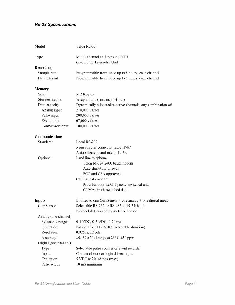
Ru-33 Specifications Model Telog Ru-33 Type Multi- channel underground RTU (Recording Telemetry Unit) Recording Sample rate Programmable from 1/sec up to 8 hours; each channel Data interval Programmable from 1/sec up to 8 hours; each channel Memory Size: 512 Kbytes Storage method Wrap around (first-in; first-out), Data capacity Dynamically allocated to active channels, any combination of: Analog input 270,000 values Pulse input 200,000 values Event input 67,000 values ComSensor input 100,000 values Communications Standard: Local RS-232 5 pin circular connector rated IP-67 Auto-selected baud rate to 19.2K Optional Land line telephone Telog M-324 2400 baud modem Auto-dial/Auto-answer FCC and CSA approved Cellular data modem Provides both 1xRTT packet switched and CDMA circuit switched data. Inputs Limited to one ComSensor + one analog + one digital input ComSensor Selectable RS-232 or RS-485 to 19.2 Kbaud. Protocol determined by meter or sensor Analog (one channel) Selectable ranges 0-1 VDC, 0-5 VDC, 4-20 ma Excitation Pulsed +5 or +12 VDC, (selectable duration) Resolution 0.025%; 12 bits Accuracy ±0.1% of full range at 25º C ±50 ppm Digital (one channel) Type Selectable pulse counter or event recorder Input Contact closure or logic driven input Excitation 5 VDC at 20 µAmps (max) Pulse width 10 mS minimum
Ru-33 Specification and User Guide Page 5

Battery Factory installed Single 6V alkaline lantern battery Eveready Energizer model 529 Battery Life Example: Input ComSensor Sigma 900 series flowmeter Sample rate Five minutes Communication Wireless 1xRTT Call schedule 5 minutes Battery life=1 month 15 minutes Battery life=3 months 2 hours Battery life=1 year 24 hours Battery life=2 years External Power Input 9 to 15 VDC @ 1 amp max Enclosure Size Cylindrical 4.5” x 15.4” Weight 7 lbs. Material PVC Environmental Temperature 0 to 70º C -30 to +70º C powered externally Submersible IP67 (NEMA 6) Support Software S-3PC Telogers for Windows S-3EP Telogers Enterprise Data transfer Unit IP-67 rated PDA running Palm OS and Telog application program
Support Software
The Ru-33 is supported by two Telog host software application products; Telogers for Windows and Telogers Enterprise. The Ru-33 was first introduced in October of 2005 with software version V3.47 of Telogers for Windows and Enterprise TCC (Telogers Communications and Configuration Module). This initial version does not provide support for all features discussed in this User Guide. Consult Telog or the Telog website for notification of current software version.
Note that Telogers for Windows and the TCC Module of Telogers Enterprise are functionally similar products and are referred to interchangeably throughout this document as either Telogers for Windows, or TCC.
Ru-33 Specification and User Guide Page 6

Telogers Overview Telogers is a data collection, communications and information management system. It is an automated system optimized for data access, communications economy, information sharing, and convenient user management. Key benefits of the Telogers system include:
• Remote site real-time and historic data access • Alarm notification and alarm forwarding management • Choice of communication technologies • Common data platform for all collection system parameters • Compatibility with proprietary flowmeters • Low power remote site operation • System scalability • Automated operation • Low procurement and lifetime operating cost of ownership
The Telogers system product model consists of three elements: the remote data recorder, communications and information management. The RTU or data recorder provides the following general functions:
• Accept a variety of analog or discrete signals from sensors and instruments • Directly interrogate digital meters and sensors via RS-232/485 • Provide configurable signal conditioning of inputs • Sample and store each input at user selectable rates • Compute statistics (i.e. min, max, averages, totals) at synchronized intervals • Provide error-free communications with the host computer Support plug-in communication modules including
Local RS-232 Cellular - Switched circuit and/or switched packet Radio – unlicensed or licensed narrow-band or spread-spectrum Ethernet Satellite
• Initiate scheduled data calls and alarm exceedance calls to the host computer • Respond to SCADA/HMI polling • Provide password protection for data access and/or configuration changes • Maintain a recorder log of all significant events, e.g. computer communications,
reprogramming events, alarm calls, fault conditions, time-clock adjustments etc. Telog RTUs may be supplied in NEMA 4x rated enclosures for above ground applications; NEMA 6 (IP-67) rated immersible enclosures for underground installations or as stand alone instruments to be mounted in existing enclosures on site. Since the Telog RTU consumes very little energy, it may be powered from battery, solar or utility power options.
Ru-33 Specification and User Guide Page 7

Smart Meter and Sensor Support The Ru-33 RTU provides support for one each of three input types; one analog input (e.g. temperature, pressure, pH sensor etc.), one discrete digital input (e.g. rain gauge, float switch, pulse output flow meter etc.) and one computer controlled sensor/meter via serial data communications, what Telog refers to as a ComSensor. The ComSensor input provides interface support for many digital sensors and meters that permit external interrogation. This includes flowmeters; smart sensors (e.g. ultrasonic and pressure transmitters with embedded micro-controllers) water quality sondes etc. The Ru-33 is configured with the firmware protocol drivers to interrogate a growing list of popular sensors and meters. ComSensor communications with external sensors and meters is performed using industry standard RS-232 or RS-485 communication protocol. The Ru-33 will auto select the appropriate serial interface protocol, baud rate and flow control methodology depending on the user selected sensor or meter. The Ru-33 is supplied with many sensor/meter protocol drivers installed and has the capacity to add support for additional sensors and meters in the future. A list of currently supported sensors and meters follows.
Currently Supported Meters and Sensors via ComSensor Interface
Manufacturer
Product Model(s) Sensor/Meter Type
Hach 910, 920, 930, 950 Wastewater Flowmeters ISCO
2150
Wastewater Flowmeter
MGD
ADFM & accQmin
Wastewater Flowmeter
Marsh McBirney
FloStations (Flodar & Flotote3)
Wastewater Flowmeters
ADS Environmental
FlowShark
Wastewater Flowmeters
Hach Hydrolab DataSonde & MiniSonde 4a
DS5X, DS5, MS5 WDM Pipe Sonde
Water Quality Sondes
Telog/Massa UT-33u/95 Ultrasonic Level Sensor
Ru-33 Specification and User Guide Page 8
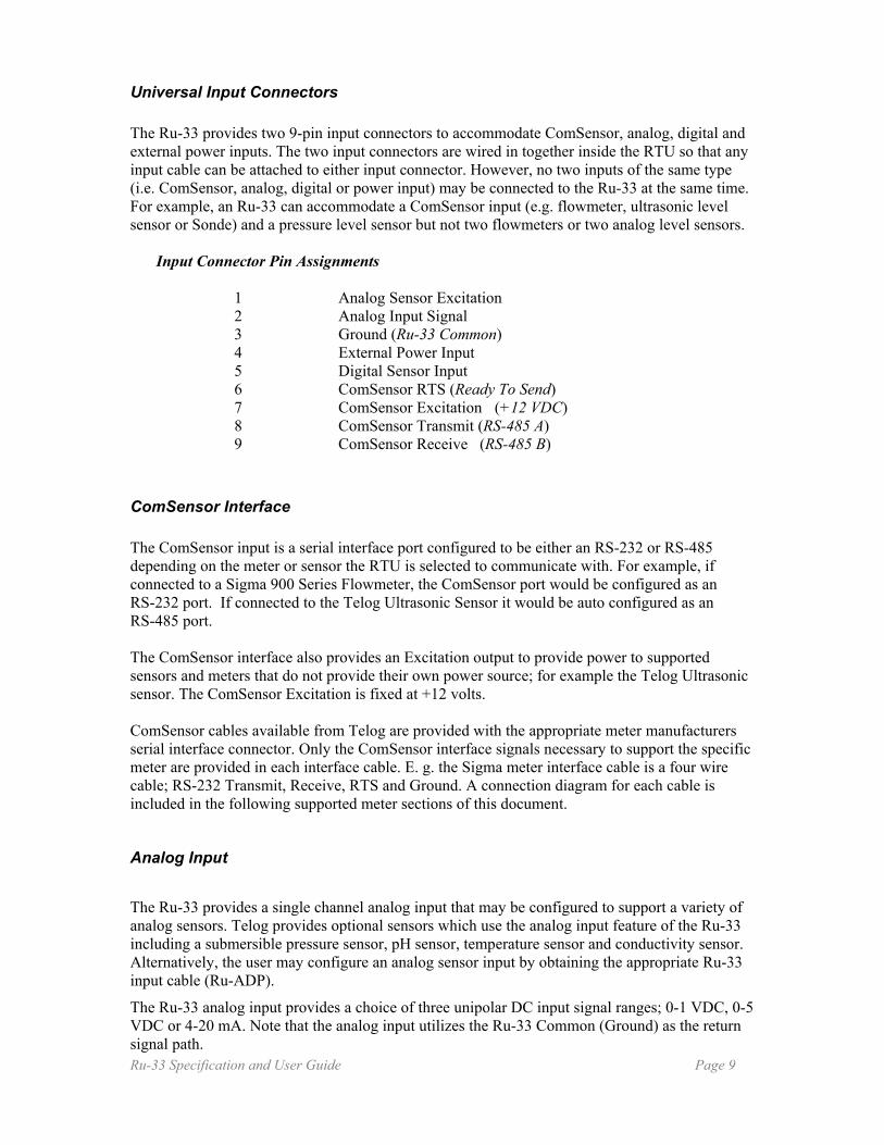
Universal Input Connectors The Ru-33 provides two 9-pin input connectors to accommodate ComSensor, analog, digital and external power inputs. The two input connectors are wired in together inside the RTU so that any input cable can be attached to either input connector. However, no two inputs of the same type (i.e. ComSensor, analog, digital or power input) may be connected to the Ru-33 at the same time. For example, an Ru-33 can accommodate a ComSensor input (e.g. flowmeter, ultrasonic level sensor or Sonde) and a pressure level sensor but not two flowmeters or two analog level sensors.
Input Connector Pin Assignments
1 Analog Sensor Excitation 2 Analog Input Signal 3 Ground (Ru-33 Common) 4 External Power Input 5 Digital Sensor Input 6 ComSensor RTS (Ready To Send) 7 ComSensor Excitation (+12 VDC) 8 ComSensor Transmit (RS-485 A) 9 ComSensor Receive (RS-485 B)
ComSensor Interface The ComSensor input is a serial interface port configured to be either an RS-232 or RS-485 depending on the meter or sensor the RTU is selected to communicate with. For example, if connected to a Sigma 900 Series Flowmeter, the ComSensor port would be configured as an RS-232 port. If connected to the Telog Ultrasonic Sensor it would be auto configured as an RS-485 port. The ComSensor interface also provides an Excitation output to provide power to supported sensors and meters that do not provide their own power source; for example the Telog Ultrasonic sensor. The ComSensor Excitation is fixed at +12 volts. ComSensor cables available from Telog are provided with the appropriate meter manufacturers serial interface connector. Only the ComSensor interface signals necessary to support the specific meter are provided in each interface cable. E. g. the Sigma meter interface cable is a four wire cable; RS-232 Transmit, Receive, RTS and Ground. A connection diagram for each cable is included in the following supported meter sections of this document.
Analog Input
The Ru-33 provides a single channel analog input that may be configured to support a variety of analog sensors. Telog provides optional sensors which use the analog input feature of the Ru-33 including a submersible pressure sensor, pH sensor, temperature sensor and conductivity sensor. Alternatively, the user may configure an analog sensor input by obtaining the appropriate Ru-33 input cable (Ru-ADP).
The Ru-33 analog input provides a choice of three unipolar DC input signal ranges; 0-1 VDC, 0-5 VDC or 4-20 mA. Note that the analog input utilizes the Ru-33 Common (Ground) as the return signal path. Ru-33 Specification and User Guide Page 9

The Ru-33 samples the analog input at a user selected rate from once per second to once per eight hours. The input sample is resolved to a 12 bit digital value (0.025% of full scale) and stored in memory. At a user defined interval rate equal to or greater than the sample rate, the recorder will compute and record a choice of statistical computations including the minimum, maximum, average and/or total value from the recorded samples, store these computed values in memory and discard the sample values used to create the interval statistics.
For example, the user may configure the RTU to sample the output of a submersible lever sensor once per second and store the maximum and average level every 5 minutes from the 300 one second samples collected during the previous interval. The sensor’s engineering units may be stored in the recorder so that all data transferred from the RTU to the host computer would appear as inches or feet of level instead of 0 to 1 volts, which might be the sensor analog output.
The analog sensor interface is also provided with an excitation level to power the sensor during a measurement. The excitation is selectable as either +5 volts or +12 volts with a user defined duration. For example, the Telog submersible pressure sensor is powered by +5 volts for a period of 5 milliseconds during each sample. This low duty cycle excitation duration permits the Ru-33 to operate from battery for extended periods.
Digital Input
The Ru-33 provides a single digital input to monitor the output of a contact closure or logic driven switch or sensor. The digital input may be selected to operate in a pulse totalizing mode or event recording mode.
In pulse totalizing mode, the RTU counts the number of events (contact closures or pulses) that occur during a user defined interval period. For example, counting the number of tips from a rain gauge in 15 minute intervals or the number of pulses per minute produced by a water meter.
In the event recording mode, the RTU will record the time stamp of a positive and/or negative transition. For example, monitoring a float switch to identify when a site goes into surcharge and when it recovers. Event recorded data is provided with a date and time stamp to one second resolution.
The digital input provides a positive voltage excitation through a high impedance (5 volts through 350k ohms) to permit detection of uncommitted contact closure inputs (switches and relays, etc.). The input will also accept voltage driven inputs and is protected to +/- 50 volts. The detection threshold of the digital input is + 2 volts.
The minimum pulse width for detection is 100 milliseconds and the maximum number of pulses per interval is 65,000.
External Power Input
The Ru-33 is powered from an internal alkaline 6 volt lantern battery. Although any common 6 volt alkaline lantern battery meeting ANSI 908 size standards can be used, we recommend and supply the Energizer 529 which is rated at 26 Amp-Hours of capacity. This is not to be confused with the Energizer EN529 which is rated at 20 Amp-Hours of capacity.
The Ru-33 may also be externally powered by a voltage source ranging from 9 VDC to 15 VDC that can source up to 1 Amp. When externally powered, the internal lantern battery will not source power to the Ru-33 and therefore acts as a back-up power source or UPS. Normal self-discharge of the Energizer 529 lantern battery is specified to be 3%/year at 20°C although Telog recommends that this battery be changed at least every 5 years when externally powered.
Ru-33 Specification and User Guide Page 10
Telog provides an optional Auxiliary Input Cable, P/N Cu-ADP (see diagram below) which can be used to connect external power to the Ru-33 as well as connect an external analog and/or digital sensor.
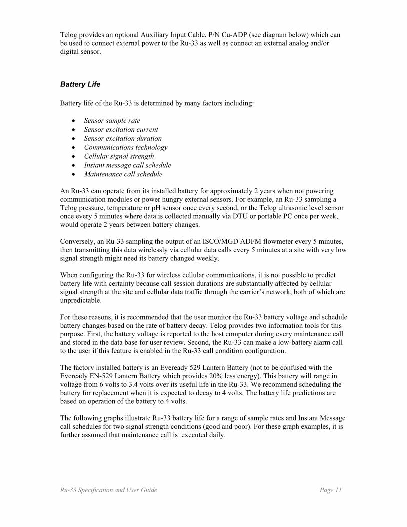
Battery Life Battery life of the Ru-33 is determined by many factors including:
• Sensor sample rate • Sensor excitation current • Sensor excitation duration • Communications technology • Cellular signal strength • Instant message call schedule • Maintenance call schedule
An Ru-33 can operate from its installed battery for approximately 2 years when not powering communication modules or power hungry external sensors. For example, an Ru-33 sampling a Telog pressure, temperature or pH sensor once every second, or the Telog ultrasonic level sensor once every 5 minutes where data is collected manually via DTU or portable PC once per week, would operate 2 years between battery changes. Conversely, an Ru-33 sampling the output of an ISCO/MGD ADFM flowmeter every 5 minutes, then transmitting this data wirelessly via cellular data calls every 5 minutes at a site with very low signal strength might need its battery changed weekly. When configuring the Ru-33 for wireless cellular communications, it is not possible to predict battery life with certainty because call session durations are substantially affected by cellular signal strength at the site and cellular data traffic through the carrier’s network, both of which are unpredictable. For these reasons, it is recommended that the user monitor the Ru-33 battery voltage and schedule battery changes based on the rate of battery decay. Telog provides two information tools for this purpose. First, the battery voltage is reported to the host computer during every maintenance call and stored in the data base for user review. Second, the Ru-33 can make a low-battery alarm call to the user if this feature is enabled in the Ru-33 call condition configuration. The factory installed battery is an Eveready 529 Lantern Battery (not to be confused with the Eveready EN-529 Lantern Battery which provides 20% less energy). This battery will range in voltage from 6 volts to 3.4 volts over its useful life in the Ru-33. We recommend scheduling the battery for replacement when it is expected to decay to 4 volts. The battery life predictions are based on operation of the battery to 4 volts. The following graphs illustrate Ru-33 battery life for a range of sample rates and Instant Message call schedules for two signal strength conditions (good and poor). For these graph examples, it is further assumed that maintenance call is executed daily.
Ru-33 Specification and User Guide Page 11

Ru-33 Specification and User Guide Page 12

Available Input Cables
Open Channel Wastewater Flowmeter Interface Cables
Cu-HAS Hach/ American Sigma 900 Series Flowmeters
CU-T/I ISCO 2150
Cu-MGD MGD ADFM & accQmin
Ru-33 Specification and User Guide Page 13

Cu-MMI Marsh McBirney Flow Logger
Cu-ADS ADS FlowShark
Water Quality Sonde Interface Cable
Cu-HHL Hach/Hydrolab Sondes (Data Sonde 4a, Mini 4a, WMD Pipe Sondes)
u
Ru-33 Specification and User Guide Page 14
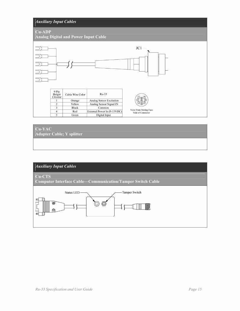
Auxiliary Input Cables
Cu-ADP Analog Digital and Power Input Cable
Cu-YAC Adapter Cable; Y splitter
Auxiliary Input Cables
Cu-CTS Computer Interface Cable—Communication/Tamper Switch Cable
Ru-33 Specification and User Guide Page 15

Ultrasonic Sensor Option Telog offers an ultrasonic sensor option to the Ru-33 to monitor water level in wastewater and surface water applications. If monitoring the level in a calibrated flume or weir, or if the level to flow relationship of an open channel is known, the Ru-33 can additionally compute and record flow in addition to level. Key features of the Telog Ru-33 with the ultrasonic sensor option include:
• Very low power operation • Digital ultrasonic sensor output • Computes flow for weirs and flumes • Easy calibration • Environmentally rugged • Low cost
The Telog ultrasonic sensor/transmitter, Model UT-33u/95 is manufactured by Massa Products Corp. (Hingham, MA), model MassaSonic™ M-5002/95 Smart Ultrasonic Sensor. The Telog ultrasonic transmitter assembly is provided with a circular environmental connector completely tested and ready to be attached to an Ru-33. The MassaSonic Smart Ultrasonic Sensor integrates an ultrasonic ranging sensor, microprocessor based sensor and transmitter electronics circuit, automatic temperature compensation, self-diagnostic software and automatic range measurement software. It is packaged in an IP-67 rated CPVC housing approximately 1-inch diameter by 4 inches in length. The Ru-33 with UT-33u/95 Ultrasonic Transmitter is intended to monitor surface or open-channel water level over a 12-foot range. Accuracy is ±0.25% of any portion of this range (exceeding 1 foot) when site calibrated in accordance with the method described in this document. This assumes a homogeneous measurement environment (temperature & humidity). Operationally, the Ru-33 executes an ultrasonic measurement by applying 12-volt excitation to the ultrasonic transmitter along with a sample command to the sensor via RS-485 over the ComSensor interface. The sensor executes multiple distance measurements and transmits these values along with the reflected ultrasonic pulse signal strength to the RTU. The RTU reviews the consistency of distance values and their signal strength then using a proprietary algorithm, computes and records the distance value. At the user’s option, the Ru-33 may record distance or level. The sample process occurs in approximately one second. The energy consumed by the ultrasonic transmitter during the sample is less than 100 µWatt-Hours permitting long-term operation on battery power. The sample rate is user configurable from once every two seconds to once every 8 hours.
Ru-33 Specification and User Guide Page 17

Ultrasonic Sensor Summary Specifications
Ultrasonic Frequency: Beam Angle Target Detection: Minimum Distance Maximum Distance Accuracy Resolution Operating Power Sampling Rate Communications Housing Dimensions Housing Material Operating Temperature Temperature Comp.
95 kHz 8° conical 1 foot (0.3 m) 13 feet (4.0 m) ± 0.25% of any measured range in homogeneous environment when calibrated per Telog procedure. .04 inches (1 mm) 12 VDC at 80 mAmps, maximum 0.1 Hz to 20 Hz RS-485, transient protected, multi-drop 30 mm Dia M-30X1.5 threaded tube, 100 mm long CPVC -20°C to 65°C Internal probe
Ru-33 Specification and User Guide Page 18

Ru-33-1x Quick Start
Connect Ru-33 to PC
The Ru-33 is typically shipped with the battery installed and the unit fully operational. The antenna (A-CBA or A-PMA) and tamper cable (Cu-CTS) are required for wireless and serial communications respectively. The serial cable connects to the five-pin circular connector. This cable provides the serial link for communications between the Ru-33 and a PC running Telogers for Windows software.
Illustration 1. Recorder ID and Serial Number is indicated on two labels; one installed on the connector cover, the second inside the battery chamber.
1. Connect the Cu-CTS serial communication cable to the Ru-33 2. Connect other end to an RS-232 port on a PC running Telogers for Windows.
The Status LED on the cable next to the Tamper Button should be flashing once per second.
Configure Comport
1. On the PC start Telogers for Windows
2. Click Setup | Options | Communications
3. Check Enable Local Comm
Ru-33 Specification and User Guide Page 19
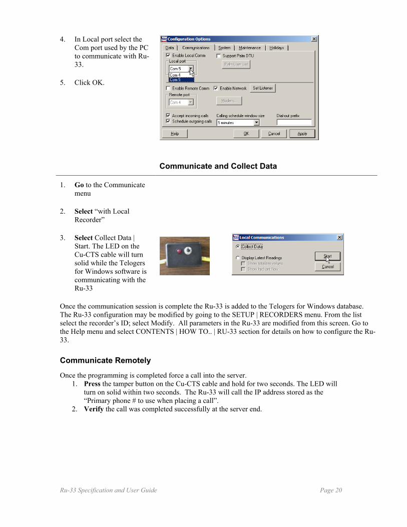
4. In Local port select the Com port used by the PC to communicate with Ru-33.
5. Click OK.
Communicate and Collect Data
1. Go to the Communicate menu
2. Select “with Local Recorder”
3. Select Collect Data | Start. The LED on the Cu-CTS cable will turn solid while the Telogers for Windows software is communicating with the Ru-33
Once the communication session is complete the Ru-33 is added to the Telogers for Windows database. The Ru-33 configuration may be modified by going to the SETUP | RECORDERS menu. From the list select the recorder’s ID; select Modify. All parameters in the Ru-33 are modified from this screen. Go to the Help menu and select CONTENTS | HOW TO.. | RU-33 section for details on how to configure the Ru-33. Communicate Remotely
Once the programming is completed force a call into the server.
1. Press the tamper button on the Cu-CTS cable and hold for two seconds. The LED will turn on solid within two seconds. The Ru-33 will call the IP address stored as the “Primary phone # to use when placing a call”.
2. Verify the call was completed successfully at the server end.
Ru-33 Specification and User Guide Page 20

How To Configure PT-1030u Pressure Sensor To Work With Ru-33
Telog Instruments provides the PT-1030u Submersible Level Transmitter as one of the optional sensors that can be attached to Ru-33. The sensor can be connected to either one of the sensor/power ports but only one analog sensor can be connected to the RTU at a time.
Every recorder must be configured prior to collecting data from the sensor. During that
process you should enter the calibration information provided by the factory with the sensor. Configuration can be performed locally by programming the RTU using Telogers for Windows, or remotely by configuring the host support software, Telogers for Windows or Telogers Enterprise TCC. The recorder must be added to the database either manually or automatically prior to host configuration.
Although all off the recorder’s channels can be modified during the configuration process, only Channel 1 of the Ru-33 is specific to the analog input. This configuration procedure describes connecting the PT-1030u as a stand alone device with the Ru-33. To learn how to add a recorder to the Telogers software review the steps for automated Ru addition: (steps and screens from the QuickStart). Once the Ru-33 is in the Telogers database you must perform the following steps to configure the analog input for the channel 1:
1. Access Recorder Configuration 2. Set Configuration 3. Define Recording 4. Set Alarms
Steps required for configuring the Communication and Security of the recorder are the same for any other type of input device.
Access Recorder Configuration 1. In TCC select: Setup|
Recorders.
2. From the dropdown menu of recorders choose the RTU you want to configure. Click Modify.
Ru-33 Specification and User Guide Page 21

Set Configuration
1. Select Channels tab. Channels configuration tab defines each input to the RTU and permits scaling of the data
2. In Configuration check the first On/Off box under turn On/Off label to permit storing sensors input.
3. In the “Channel Type” select the first choice: Voltage to collect sensor’s input.
4. Set “Channel Range” to the 0-5 Volts range
5. To define scaling click on scaling button. In the Channel scaling enter the scaling provided by the factory. Note: If you receive an advisory about changing the alarms, accept it. You will configure alarms in the next step.
6. Under “Enunciation Type” select the voltage appropriate for the input: 5 Volts.
7. Set the “Excitation Delay (ms)” to 10 .
Ru-33 Specification and User Guide Page 22

8. To save the changes to Channel 1 click OK, or if the recorder is connected locally, click program. If you want to continue configuring recording select another tab.
Define Recording
1. Select Recording tab.
2. Ensure that check is present in the following three settings for Channel 1: Min, Avg, Max.
3. Select Mode button must be used if the recording has to be performed in Alarm conditions only. Review the settings for recording modes.
4. Click the arrow next to Sample Rate button to adjust how often the sensor will sample the pressure. Select desirable time interval.
5. Set the time of recording interval under Rec Intvl. This setting will delineate how often the recorder will store the data from the sample readings.
Ru-33 Specification and User Guide Page 23

6. Click “Capacity…” to review the impact a recording interval setting has on the storage capacity of the recorder.
7. To save the changes to Channel 1 click OK, or if the recorder is connected locally click program. If you want to continue configuring a recording select another tab.
Set Alarms
1. Select Alarms tab.
2. To review the levels and dwell time scroll the bar below the configuration box. Four sets of alarms are available: Lo-Lo, Lo, Hi and Hi-Hi.
3. To prompt the recorder to send an alarm message check the box below the alarm’s name: i.e.: Hi.
4. Type in the required number under Alarm Level.
Ru-33 Specification and User Guide Page 24

5. Select the Dwell Time you want the recorder to wait before setting the alarm. Note: Dwell time is the multiplication of the Recording Interval set during the configuration of the Record tab.
6. To change the message associated with the alarm click the “Message” button. Note: By default two messages will be sent: One at the time the alarm condition was logged and the second at the time the recorder logged return to normal state.
7. Repeat steps three through six for all alarm conditions you want to set.
8. To save the changes to Channel 1 click OK, or if recorder is connected locally click program. If you want to continue configuring recording select another tab.
Ru-33 Specification and User Guide Page 25
How To Configure Locally Connected Ru-33 To Interface With Sigma Flowmeter Flexibility of the Ru-33 design allows for configuring remotely or locally. Telog Instruments recommends that all recorders, prior to deployment, are configured and added to the database using local communication. The following process describes steps for configuring and adding the recorder to the database.
Configure COM Port ....................................................................................... page 26 Auto Add Recorder—Collect Data.................................................................. page 27 Enable TCC To Program Recorder.................................................................. page 27 Assign Template .............................................................................................. page 28 Configure Channels ......................................................................................... page 29 Configure Communications............................................................................. page 31 Set The Security............................................................................................... page 33 Program Locally Connected Recorder............................................................. page 33
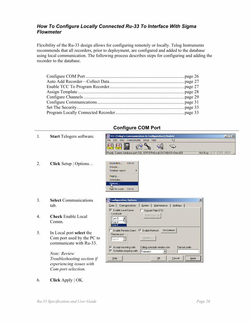
Configure COM Port 1. Start Telogers software.
2. Click Setup | Options…
3. Select Communications tab.
4. Check Enable Local Comm.
5. In Local port select the Com port used by the PC to communicate with Ru-33. Note: Review Troubleshooting section if experiencing issues with Com port selection.
6. Click Apply | OK.
Ru-33 Specification and User Guide Page 26

Auto-add Recorder—Collect Data
1. Click on Communicate | with Local recorder…
2. Ensure that LED on the Serial Interface & Tamper Cable flashes every second. Select Collect Data and click Start.
Note: If the annunciation window appears during programming, investigate the message in Help File | Alarm Enunciate.
Note: When communication is successful the status bar displays messages describing the stages of communication: i.e.: “Auto-adding recorder 291173 to the database. Busy”. Another indication of successful communication is the LED staying on when the software and recorder are communicating. If communication has not been successful (no change to the status bar) verify the cables connecting the recorder to PC are secure and review the steps in Configure COM port to change COM port.
Enable TCC To Program Recorder
1. To enable programming of the recorder click lock icon to set it in open position.
2. Once lock is in open position recorder can be programmed.
Ru-33 Specification and User Guide Page 27

Assign Template
1. Click on Setup.
2. Select Recorders…
3. Scroll down the list and select the recorder you want to modify.
4. Click Modify…
5. In Recorder tab Click Templates… Note: Review the summary of the steps for configuring Ru-33. To remove the summary click “X”.
6. Scroll down in Available Templates window to the template you want to assign to a recorder then select this template.
Ru-33 Specification and User Guide Page 28

7. Click Restore.
8. Click Yes.
9. To complete modifications click OK, if there are changes you want to implement in other areas of recorder you can select appropriate tab. Note: Recorder Type will change to flowmeter specific information. If you want to accept the default settings of the template click OK. To continue configuration of the recorder review and change the settings in other tabs.
Configure Channels 1. To adjust input channels
select Channels tab. Note: The recorder configuration is set to factory defaults. Review the settings and adjust them to meet your requirements. If Telogers software is open use F1 function key to access the page in the Help file that corresponds with the active window.
Ru-33 Specification and User Guide Page 29

Note: If required to view additional portions of the screen scroll the bar to the right to see all of the configuration settings, or select standard operating system expand icon to get a full widow view.
2. In the Configuration tab click the boxes under turn On/Off label to permit or disallow storing sensor’s data. Note: Telog recommends maintaining factory setting for channel 3 to permit local power supply monitoring.
3. Adjust the scaling if required.
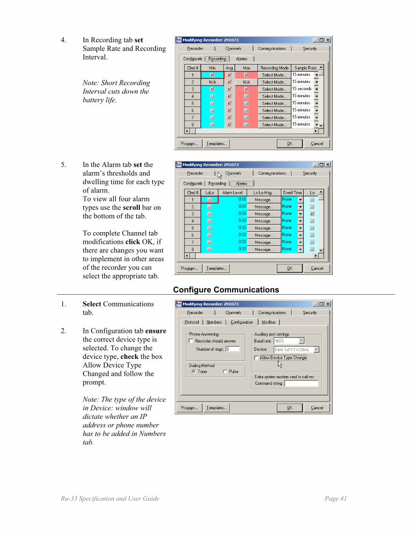
4. In Recording tab set Sample Rate and Recording Interval. Note: Short Recording Interval cuts down the battery life.
5. In the Alarm tab set the alarm’s thresholds and dwelling time for each type of alarm. To view all four alarm types use the scroll bar on the bottom of the tab. To complete Channel tab modifications click OK, if there are changes you want to implement in other areas of recorder you can select appropriate tab.
Ru-33 Specification and User Guide Page 30

Configure Communications
1. Select Communications tab.
2. In Configuration tab ensure the correct device type is selected. To change the device type, check the box Allow Device Type Changed and follow the prompt. Note: The type of the device in Device: window will dictate whether an IP address or phone number has to be added in Numbers tab.
3. For the battery operated systems remove check box from the Phone Answering check box. Note: Removing the check from the “Recorder should answer”, prevents the device from draining the battery.
4. Select Numbers tab. Make no changes to “IP or Phone...” area nor to the “Call schedule…” settings. Note: Most recorders shipped from the factory have a default configuration that will connect them to the Telog host. Review the settings and adjust them to meet your requirements. If Telogers software is open use F1 function key to access the page in the Help file that corresponds with the active window.
Ru-33 Specification and User Guide Page 31

5. Click inside of area titled IP address of primary workstation and enter the IP address/TCP port of the server the Ru-33 will communicate with. If necessary configure the secondary IP entry. Note: Choice of the device in Configuration | Device: window will dictate whether an IP address or phone number has to be added.
7. Click “Use when…” and select the triggers to initiate a call each number. Click OK to accept the changes. Note: At a minimum Telog recommends using triggers selected in the graphic. To select settings best fitting your application review Telogers Help File | When To Call.
8. Select the same baud rate that is used in the Sigma meter the recorder connects to.
Ru-33 Specification and User Guide Page 32

9. Unless advised by Telog technician, make no changes to the Protocol tab. To complete the Communication tab modifications click OK, if there are changes you want to implement in other areas of recorder you can select the appropriate tab.
Set The Security 1. In Modifying Recorder:
select Security. Note: Before making changes to the Security settings read security and password information in Telogers Help.
2. Set the security passwords and select appropriate permissions. To complete the Security tab modifications click OK.
Program Locally Connected Recorder 1. Remember that to enable
programming of the local recorder the lock icon in the control panel has to be in open position.
2. Ensure that Serial Interface & Tamper Cable is connected to PC and that LED on the cable flashes every second.
Ru-33 Specification and User Guide Page 33
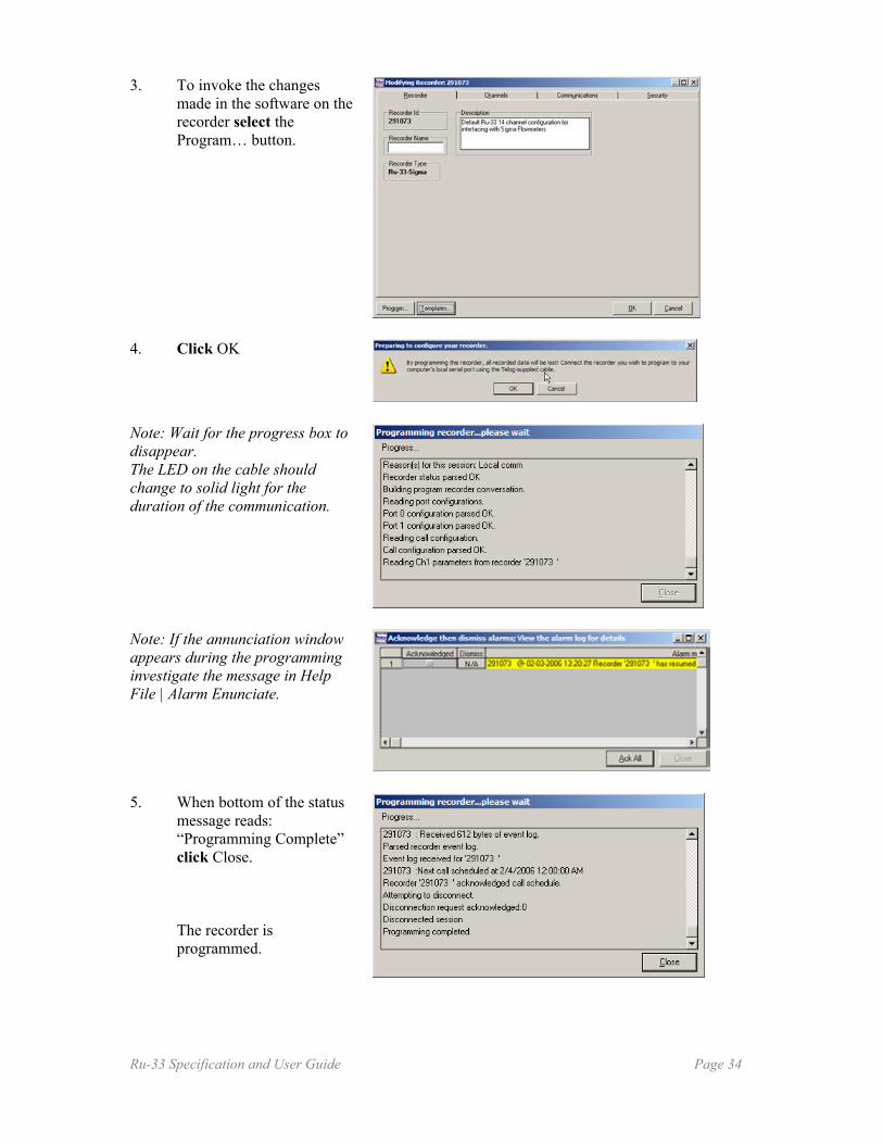
3. To invoke the changes made in the software on the recorder select the Program… button.
4. Click OK
Note: Wait for the progress box to disappear. The LED on the cable should change to solid light for the duration of the communication.
Note: If the annunciation window appears during the programming investigate the message in Help File | Alarm Enunciate.
5. When bottom of the status message reads: “Programming Complete” click Close. The recorder is programmed.
Ru-33 Specification and User Guide Page 34
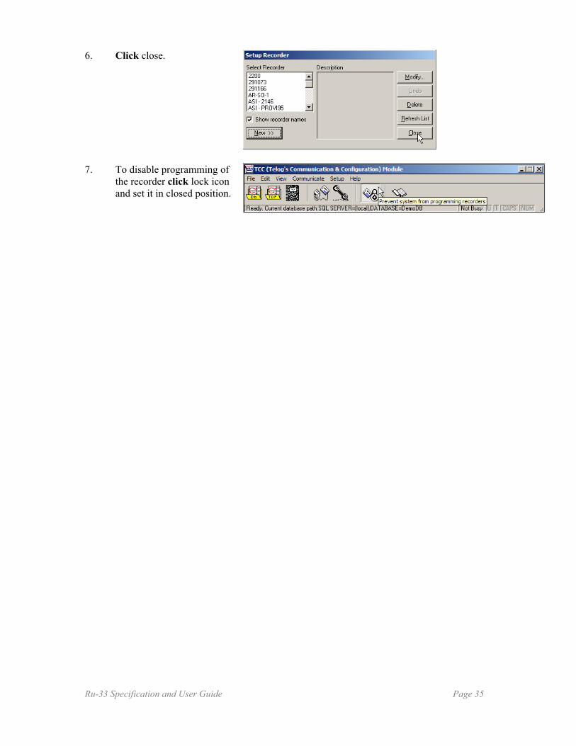
6. Click close.
7. To disable programming of the recorder click lock icon and set it in closed position.
Ru-33 Specification and User Guide Page 35
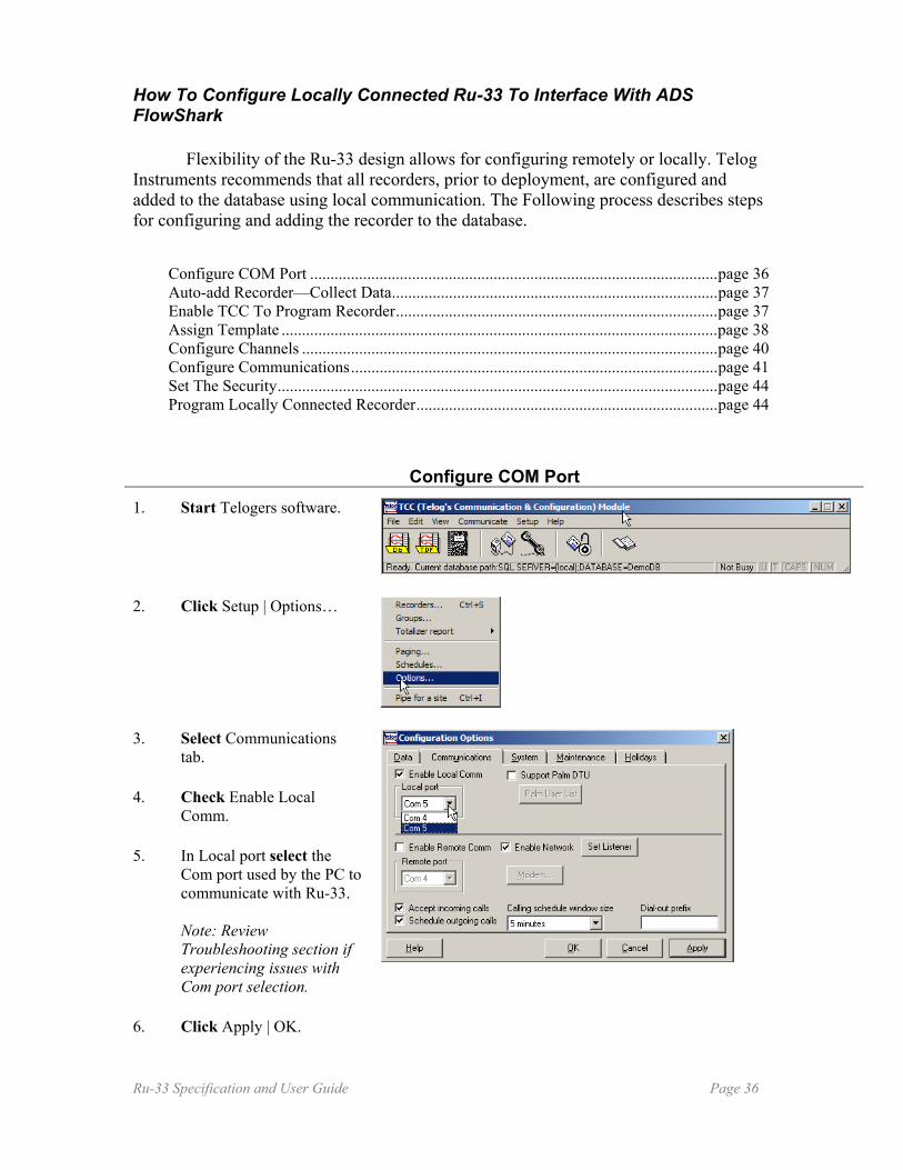
How To Configure Locally Connected Ru-33 To Interface With ADS FlowShark
Flexibility of the Ru-33 design allows for configuring remotely or locally. Telog Instruments recommends that all recorders, prior to deployment, are configured and added to the database using local communication. The Following process describes steps for configuring and adding the recorder to the database.
Configure COM Port ....................................................................................................page 36 Auto-add Recorder—Collect Data................................................................................page 37 Enable TCC To Program Recorder...............................................................................page 37 Assign Template ...........................................................................................................page 38 Configure Channels ......................................................................................................page 40 Configure Communications..........................................................................................page 41 Set The Security............................................................................................................page 44 Program Locally Connected Recorder..........................................................................page 44
Configure COM Port 1. Start Telogers software.
2. Click Setup | Options…
3. Select Communications tab.
4. Check Enable Local Comm.
5. In Local port select the Com port used by the PC to communicate with Ru-33. Note: Review Troubleshooting section if experiencing issues with Com port selection.
6. Click Apply | OK.
Ru-33 Specification and User Guide Page 36
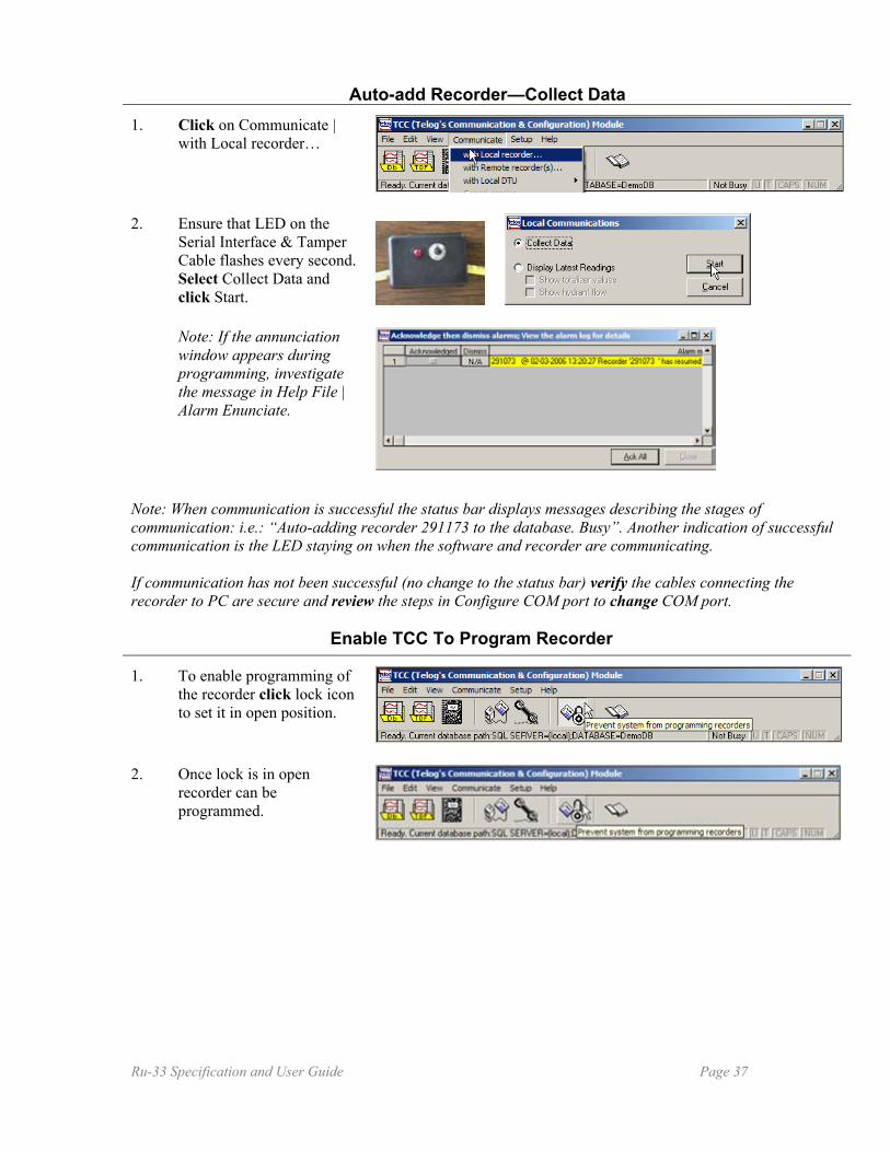
Auto-add Recorder—Collect Data
1. Click on Communicate | with Local recorder…
2. Ensure that LED on the Serial Interface & Tamper Cable flashes every second. Select Collect Data and click Start.
Note: If the annunciation window appears during programming, investigate the message in Help File | Alarm Enunciate.
Note: When communication is successful the status bar displays messages describing the stages of communication: i.e.: “Auto-adding recorder 291173 to the database. Busy”. Another indication of successful communication is the LED staying on when the software and recorder are communicating. If communication has not been successful (no change to the status bar) verify the cables connecting the recorder to PC are secure and review the steps in Configure COM port to change COM port.
Enable TCC To Program Recorder
1. To enable programming of the recorder click lock icon to set it in open position.
2. Once lock is in open recorder can be programmed.
Ru-33 Specification and User Guide Page 37
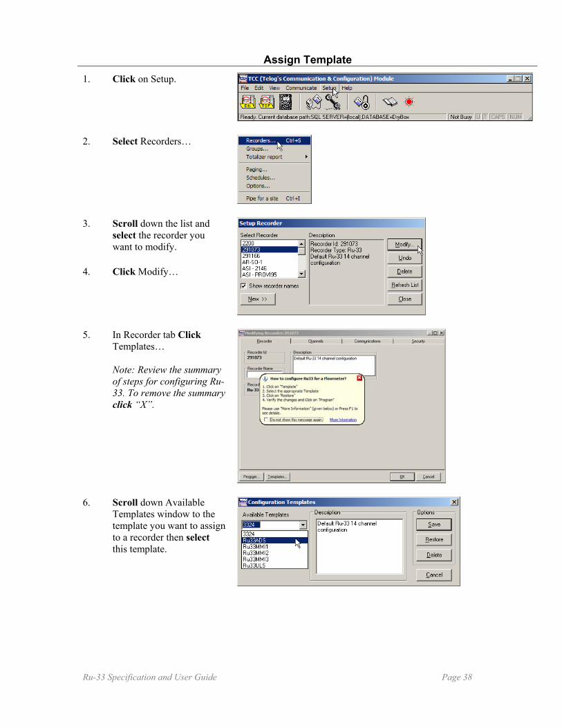
Assign Template
1. Click on Setup.
2. Select Recorders…
3. Scroll down the list and select the recorder you want to modify.
4. Click Modify…
5. In Recorder tab Click Templates… Note: Review the summary of steps for configuring Ru-33. To remove the summary click “X”.
6. Scroll down Available Templates window to the template you want to assign to a recorder then select this template.
Ru-33 Specification and User Guide Page 38

7. Click Restore.
8. Click Yes.
9. To complete modifications click OK, if there are changes you want to implement in other areas of the recorder you can select the appropriate tab. Note: Recorder Type will change to flowmeter specific information. If you want to accept the default settings of the template click OK. To continue configuration of the recorder, review and change the settings in other tabs.
Ru-33 Specification and User Guide Page 39

Configure Channels
1. To adjust input channels select Channels tab. Note: The recorder configuration is set to factory defaults. Review the settings and adjust them to meet your requirements. If Telogers software is open use F1 function key to access the page in the Help file that corresponds with the active window.
2. In the Configuration tab click the boxes under turn On/Off label to permit or disallow storing sensor’s data. Note: If required to view additional portions of the screen, use the scroll bar on the right to view all configuration settings, or select standard operating system expand icon to get a full window view.
Note: Telog recommends maintaining factory setting for channel 3 to permit local power supply monitoring.
3. Adjust the scaling if required.
Ru-33 Specification and User Guide Page 40
4. In Recording tab set Sample Rate and Recording Interval. Note: Short Recording Interval cuts down the battery life.
5. In the Alarm tab set the alarm’s thresholds and dwelling time for each type of alarm. To view all four alarm types use the scroll bar on the bottom of the tab. To complete Channel tab modifications click OK, if there are changes you want to implement in other areas of the recorder you can select the appropriate tab.
Configure Communications 1. Select Communications
tab.
2. In Configuration tab ensure the correct device type is selected. To change the device type, check the box Allow Device Type Changed and follow the prompt. Note: The type of the device in Device: window will dictate whether an IP address or phone number has to be added in Numbers tab.
Ru-33 Specification and User Guide Page 41
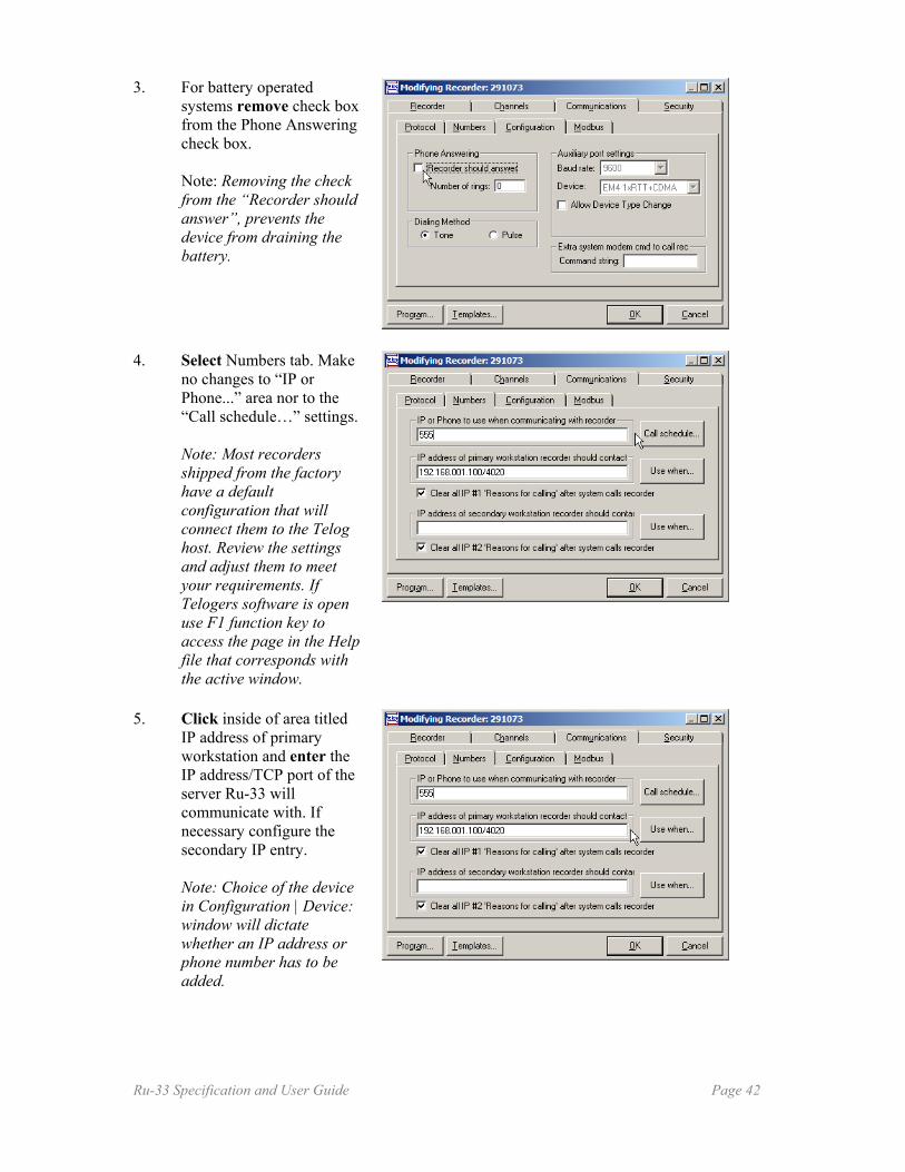
3. For battery operated systems remove check box from the Phone Answering check box. Note: Removing the check from the “Recorder should answer”, prevents the device from draining the battery.
4. Select Numbers tab. Make no changes to “IP or Phone...” area nor to the “Call schedule…” settings. Note: Most recorders shipped from the factory have a default configuration that will connect them to the Telog host. Review the settings and adjust them to meet your requirements. If Telogers software is open use F1 function key to access the page in the Help file that corresponds with the active window.
5. Click inside of area titled IP address of primary workstation and enter the IP address/TCP port of the server Ru-33 will communicate with. If necessary configure the secondary IP entry. Note: Choice of the device in Configuration | Device: window will dictate whether an IP address or phone number has to be added.
Ru-33 Specification and User Guide Page 42
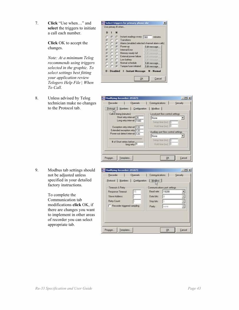
7. Click “Use when…” and select the triggers to initiate a call each number. Click OK to accept the changes. Note: At a minimum Telog recommends using triggers selected in the graphic. To select settings best fitting your application review Telogers Help File | When To Call.
8. Unless advised by Telog technician make no changes to the Protocol tab.
9. Modbus tab settings should not be adjusted unless specified in your detailed factory instructions. To complete the Communication tab modifications click OK, if there are changes you want to implement in other areas of recorder you can select appropriate tab.
Ru-33 Specification and User Guide Page 43
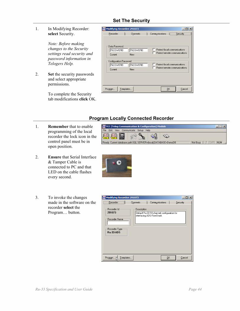
Set The Security 1. In Modifying Recorder:
select Security. Note: Before making changes to the Security settings read security and password information in Telogers Help.
2. Set the security passwords and select appropriate permissions. To complete the Security tab modifications click OK.
Program Locally Connected Recorder 1. Remember that to enable
programming of the local recorder the lock icon in the control panel must be in open position.
2. Ensure that Serial Interface & Tamper Cable is connected to PC and that LED on the cable flashes every second.
3. To invoke the changes made in the software on the recorder select the Program… button.
Ru-33 Specification and User Guide Page 44

4. Click OK
Note: Wait for the progress box to disappear. The LED on the cable should change to solid light for the duration of the communication.
Note: If the annunciation window appears during the programming investigate the message in Help File | Alarm Enunciate.
5. When bottom of the status message reads: “Programming Complete” click Close. The recorder is programmed.
6. Click close.
7. To disable programming of the recorder click lock icon to set it in closed position.
Ru-33 Specification and User Guide Page 45

How To Configure Conductivity Sensor To Work With Ru-33 Telog Instruments provides the conductivity sensor as one of the optional instruments that can be attached to Ru-33. The sensor can be connected to either one of the sensor/power ports but only one analog sensor can be utilized by the RTU at the time. Every recorder must be configured prior to collecting the data from the sensor. During that process you should enter the calibration information provided by the factory with every shipped sensor. Configuration can be performed in both Enterprise (server, TEC) and in the standalone applications (Telogers for Windows, TCC). Telogers for Windows Lite does not support Ru-33 configurations and must be upgraded to the fully functional software version. The recorder must be added to the database either manually or automatically prior to configuration. Scaling of the sensor requires the information stored on the cable next to connector.
NOTES:
1. Strip jacket back 1".2. Strip conductor to 3/8".3. Crimp on male pins with wire exposed.4. Solder and fill pin cups.5. Solder cups of 6 unused pins and insert into unused holes.
???
Cable Wire Color(SN1 Sensor)
9 PinBulgin(JC1)
BlackRed
White
312
SN1 JC1, JA1
VIEW FROM WIRE SIDE(NON MATING FACE)
12
34567
98
SALES #:
SENSOR
XXX
Master
Dependents
.xx +/- 0.01
.xxx +/- 0.005
Angular:Fractional:
Decimal:
(EXCEPT AS NOTED)TOLERANCE
+/- 3 Deg A03/08/2006
11NoneScale
Approved
Checked
Fax: 585-742-3006
Phone: 585-742-3000
Victor, NY 14564-8940830 Canning Parkway
ofSheetFileDrawn ByDate
RevisionNumberSize
TitleTELOG INSTRUMENTS INC. CABLE,CONDUCTIVITY SENSOR
C-Ru-CONDUCTIVITY A0
J CALABRO
C-Ru-CONDUCTIVITY.CAD
Approved
Graphic 1: Drawing of the sensor with the cable and Ru-33 connector Although all off the recorder’s channels can be modified during the process, only Channel 1 of the Ru-33 controls the analog inputs and must be configured. This channel’s configuration allows connecting the as a stand alone device with the Ru-33. It also supports the functionality of a flowmeter or a digital sensor attached to the second sensor/power port of the recorder. Once the Ru-33 is in the TCC database you must perform the following steps to configure analog input for the channel 1:
1. Access Recorder Configuration 2. Set Configuration 3. Define Recording 4. Set Alarms
This document covers the first two steps for configuring the Ru-33. Steps required for setting the security of the recorder are the same for any other type of input device. The Communication tab configuration depends on selection of Ru-33 communication option but is independent of the input device.
Ru-33 Specification and User Guide Page 46

Access Recorder Configuration 1. In TCC select: Setup|
Recorders.
2. From the dropdown menu of recorders choose the RTU you want to configure. Click Modify.
Set Configuration 1. Select Channels tab.
Channels configuration tab defines each input to the RTU and permits scaling of the data
2. In Configuration check the first On/Off box under turn On/Off label to permit storing sensors input.
3. In the “Channel Type” select Current Loop to collect sensor’s input.
4. The “Channel Range” is by default set to 4-20 mAmps.
Ru-33 Specification and User Guide Page 47
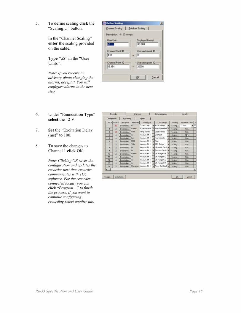
5. To define scaling click the “Scaling…” button. In the “Channel Scaling” enter the scaling provided on the cable. Type “uS” in the “User Units”. Note: If you receive an advisory about changing the alarms, accept it. You will configure alarms in the next step.
6. Under “Enunciation Type” select the 12 V.
7. Set the “Excitation Delay (ms)” to 100.
8. To save the changes to Channel 1 click OK. Note: Clicking OK saves the configuration and updates the recorder next time recorder communicates with TCC software. For the recorder connected locally you can click “Program…” to finish the process. If you want to continue configuring recording select another tab.
Ru-33 Specification and User Guide Page 48