Embed Size (px)
Citation preview

RTU-DNET DeviceNet Remote I/O Communication Module
Application Manual
DVP-0214120-04

DeviceNet Remote I/O Communication Module RTU-DNET
DVP-PLC Application Manual i
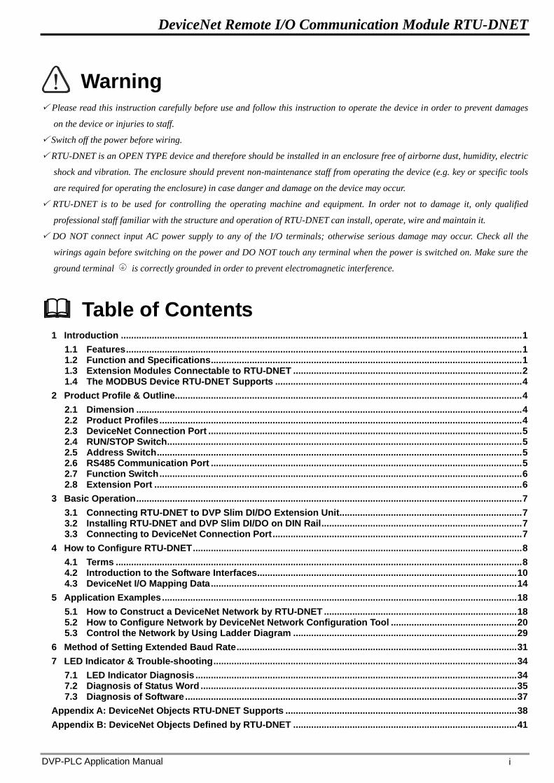
Warning Please read this instruction carefully before use and follow this instruction to operate the device in order to prevent damages
on the device or injuries to staff.
Switch off the power before wiring.
RTU-DNET is an OPEN TYPE device and therefore should be installed in an enclosure free of airborne dust, humidity, electric
shock and vibration. The enclosure should prevent non-maintenance staff from operating the device (e.g. key or specific tools
are required for operating the enclosure) in case danger and damage on the device may occur.
RTU-DNET is to be used for controlling the operating machine and equipment. In order not to damage it, only qualified
professional staff familiar with the structure and operation of RTU-DNET can install, operate, wire and maintain it.
DO NOT connect input AC power supply to any of the I/O terminals; otherwise serious damage may occur. Check all the
wirings again before switching on the power and DO NOT touch any terminal when the power is switched on. Make sure the
ground terminal is correctly grounded in order to prevent electromagnetic interference.
Table of Contents
1 Introduction ............................................................................................................................................................ 1
1.1 Features .......................................................................................................................................................... 1 1.2 Function and Specifications ......................................................................................................................... 1 1.3 Extension Modules Connectable to RTU-DNET ......................................................................................... 2 1.4 The MODBUS Device RTU-DNET Supports ................................................................................................ 4
2 Product Profile & Outline....................................................................................................................................... 4
2.1 Dimension ...................................................................................................................................................... 4 2.2 Product Profiles ............................................................................................................................................. 4 2.3 DeviceNet Connection Port .......................................................................................................................... 5 2.4 RUN/STOP Switch .......................................................................................................................................... 5 2.5 Address Switch .............................................................................................................................................. 5 2.6 RS485 Communication Port ......................................................................................................................... 5 2.7 Function Switch ............................................................................................................................................. 6 2.8 Extension Port ............................................................................................................................................... 6
3 Basic Operation ...................................................................................................................................................... 7
3.1 Connecting RTU-DNET to DVP Slim DI/DO Extension Unit ....................................................................... 7 3.2 Installing RTU-DNET and DVP Slim DI/DO on DIN Rail .............................................................................. 7 3.3 Connecting to DeviceNet Connection Port ................................................................................................. 7
4 How to Configure RTU-DNET ................................................................................................................................ 8
4.1 Terms .............................................................................................................................................................. 8 4.2 Introduction to the Software Interfaces ..................................................................................................... 10 4.3 DeviceNet I/O Mapping Data ....................................................................................................................... 14
5 Application Examples .......................................................................................................................................... 18
5.1 How to Construct a DeviceNet Network by RTU-DNET ........................................................................... 18 5.2 How to Configure Network by DeviceNet Network Configuration Tool ................................................. 20 5.3 Control the Network by Using Ladder Diagram ....................................................................................... 29
6 Method of Setting Extended Baud Rate ............................................................................................................. 31
7 LED Indicator & Trouble-shooting ...................................................................................................................... 34
7.1 LED Indicator Diagnosis ............................................................................................................................. 34 7.2 Diagnosis of Status Word ........................................................................................................................... 35 7.3 Diagnosis of Software ................................................................................................................................. 37
Appendix A: DeviceNet Objects RTU-DNET Supports .......................................................................................... 38
Appendix B: DeviceNet Objects Defined by RTU-DNET ....................................................................................... 41

DeviceNet Remote I/O Communication Module RTU-DNET
DVP-PLC Application Manual 1
1 Introduction
1. Thank you for choosing Delta RTU-DNET. To ensure correct installation and operation of RTU-DNET, please
read this chapter carefully before using your RTU-DNET.
2. This chapter only provides introductory information on RTU-DNET. For more detailed information on
DeviceNet protocol, please refer to relevant references or literatures.
3. RTU-DNET is defined as DeviceNet slave and its IO extension ports are used to connect Slim DI/DO module
and special module. Its RS-485 port is used to connect Modbus device such as the AC motor drive, servo
drive, temperature controller, PLC and so on.
4. RTU-DNET is a remote I/O communication module applicable to the connection between DeviceNet and DVP
Slim DIDO module and special modules. RTU-DNET offers functions such as status diagnosis, error
treatment and so on.
1.1 Features
Supports the standard DeviceNet communication protocol as DeviceNet slave
Supports explicit connection via predefined Master/Slave connection set.
Supports polling
The network configuration software DeviceNet Builder provides the graphic configuration interface,
automatically scans and recognizes the extension module, configures CR register of special module as IO
material, sets the methods to deal with the errors and diagnoses the error status of each module.
According to the actual demand, user selects whether to retain the data in the buffer register information
when the network is off line.
Max. 128 digital input points, 128 digital output points and max. 8 special modules extentendable
Supports MODBUS communication protocol and can be connected to 8 MODBUS devices.
1.2 Function and Specifications
DeviceNet Connection
Transmission Method CAN
Electrical Isolation 500 VDC
Interface Removable connector (5.08mm)
Transmission Cable 2-wire twister shielded cable with 2-wire bus power and drain
DeviceNet Communication
Communication
Protocol Standard DeviceNet communication protocol
Message Type I/O polling, explicit, Group 2 only servers
Baud Rates
Standard: 125 kbps; 250 kbps; 500 kbps
Extension: 10 kbps; 20 kbps; 50 kbps; 125 kbps; 250 kbps; 500 kbps; 800kbps;1M
kbps

DeviceNet Remote I/O Communication Module RTU-DNET
DVP-PLC Application Manual 2
RS-485 communication port
Baud rate 2400bps; 4800 bps; 9600 bps; 19200 bps; 38400 bps; 57600 bps; 115200 bps
Communication
Protocol Standard MODBUS communication protocol
Transmission Format
<7,E,1>ASCII <8,E,1>ASCII/RTU
<7,O,1>ASCII <8,O,1>ASCII/RTU
<7,E,2,>ASCII <8,N,1>ASCII/RTU
<7,O,2,>ASCII <8,N,2>ASCII/RTU
Transmission Cable 2-wire twister shielded cable
Electrical specification
Voltage 11 ~ 25 VDC, supplied by DeviceNet network
Current 60mA
Environment
Noise Immunity
ESD (IEC 61131-2, IEC 61000-4-2): 8KV Air Discharge
EFT (IEC 61131-2, IEC 61000-4-4): Power Line: 2KV, Digital I/O: 1KV
Analog & Communication I/O: 1KV
Damped-Oscillatory Wave: Power Line: 1KV, Digital I/O: 1KV
RS (IEC 61131-2, IEC 61000-4-3): 26MHz ~ 1GHz, 10V/m
Operation 0ºC ~ 55ºC (temperature); 50 ~ 95% (humidity); pollution degree 2
Storage -25ºC ~ 70ºC (temperature); 5 ~ 95% (humidity)
Vibration/shock
resistance
Standard: IEC 61131-2, IEC 68-2-6 (TEST Fc)/IEC 61131-2 & IEC 68-2-27 (TEST
Ea)
Certificates IEC 61131-2, UL508
1.3 Extension Modules Connectable to RTU-DNET
RT
U-D
NE
T
DV
P-0
2D
A
DV
P-0
8S
T
DV
P-1
6S
P
DV
P-0
4A
D
DV
P-0
4T
C
DV
P-0
4P
T

DeviceNet Remote I/O Communication Module RTU-DNET
DVP-PLC Application Manual 3
DVP Slim DI/DO extension units connectable to RTU-DNET
Slim DI/DO
(model name)
Default I/O mapping data
(DeviceNet → RTU-DNET)
Default I/O mapping data
(RTU-DNET → DeviceNet)
DVP08SM11N N/A 8 bits
DVP08SM10N N/A 8 bits
DVP16SM11N N/A 16 bits
DVP06SN11R 8 bits N/A
DVP08SN11R/T 8 bits N/A
DVP08SN11TS 8 bits N/A
DVP16SN11T 16 bits N/A
DVP16SN11TS 16 bits N/A
DVP08SP11R/T 8 bits 8 bits
DVP08SP11TS 8 bits 8 bits
DVP16SP11R/T 8 bits 8 bits
DVP16SP11TS 8 bits 8 bits
DVP32SM11N N/A 32 bits
DVP32SN11TN 32 bits N/A
DVP08ST11N N/A 8 bits
Special modules connectable to RTU-DNET
Special module
(model name)
Default I/O mapping data
(DeviceNet → RTU-DNET)
Default I/O mapping data
(RTU-DNET → DeviceNet)
Start CR Length (words) Start CR Length (words)
DVP02DA-S CR#10 2 N/A N/A
DVP04DA-S CR#6 4 N/A N/A
DVP04AD-S N/A N/A CR#12 4
DVP06AD-S N/A N/A CR#12 6
DVP04TC-S N/A N/A CR#14 4
DVP04PT-S N/A N/A CR#18 4
DVP06XA-S CR#10 2 CR#12 4
DVP01PU-S CR#42 4 CR#33 4
Note:
While connected to a special module, the start CR and length of uploaded/download data of RTU-DNET can be set
up in DeviceNet network configuration tool.

DeviceNet Remote I/O Communication Module RTU-DNET
DVP-PLC Application Manual 4
1.4 The MODBUS Device RTU-DNET Supports
RTU-DNET supports the standard MODBUS protocol and therefore it supports MODBUS devices like Delta motor
drive, Delta servo drive, Delta temperature controller, Delta PLC and etc.
Note:
RTU-DNET is always used as the MODBUS master and the MODBUS device connected with it is under its
control.
The communication format of MODBUS device should be the same as that of RTU-DNET.
2 Product Profile & Outline
2.1 Dimension
91
RUN
STOP
7
6
8
91 0
23
0
54
x100
IN 0IN 1
DR 1
DR 0
RT
U-D
NE
T
POWER
MSRUN
ALARM78
64
23
x101
NS 5
Unit: mm
2.2 Product Profiles
-
x10
IN 0IN 1
DR 1
DR 0
RT
U-D
NE
T
x10
2
3
5
4
6
7
8
9
10
11
12
1
13
1. Extension port 8. RUN indicator
2. Address switch 9. ALARM indicator
3. Function switch 10. DeviceNet connection port
4. RUN/STOP switch 11. DIN rail
5. POWER indicator 12. DIN rail clip
6. MS (Module Status) indicator 13. RS485 communication port
7. NS (Network Status) indicator

DeviceNet Remote I/O Communication Module RTU-DNET
DVP-PLC Application Manual 5
2.3 DeviceNet Connection Port
The connector is used for the connection to DeviceNet. Wire by using the connector enclosed with RTU-DNET.
PIN Signal Color Content
1
2
3
4
5
1 V- Black 0 VDC
2 CAN_L Blue Signal-
3 SHIELD - Shielded
4 CAN_H White Signal+
5 V+ Red 24 VDC
2.4 RUN/STOP Switch
RUN/STOP action Explanation
R U N
S T O P
STOP → RUN
1. Re-detecting the extension module.
2. Reading/writing the data in the extension
module.
RUN → STOP Stop reading/writing the data in the extension
module.
2.5 Address Switch
The switch is used for setting up the node address of RTU-DNET on DeviceNet. Range: 00 ~ 63 (64 ~ 99 are
forbidden).
Switch setting Content
91
645
0
091
32
78
2
5 64
3
78
0 ~ 63 Valid DeviceNet node address
64 ~ 99 Invalid DeviceNet node address
Example: If you need to set the node address of RTU-DNET to 26, simply switch the corresponding switch of x101
to 2 and the corresponding switch of x100 to 6.
Notes:
Please set up the node address when the power is switched off. After the setup is completed, re-power
RTU-DNET.
When RTU-DNET is operating, changing the setting of node address will be invalid.
Use slotted screwdriver to rotate the switch carefully in case you scratch the switch.
2.6 RS485 Communication Port
Pin Signal Content
3
1 + Signal+
2 - Signal-
3 SG GND

DeviceNet Remote I/O Communication Module RTU-DNET
DVP-PLC Application Manual 6
2.7 Function Switch
The function switches are for:
Setting up data retention function (IN0)
Setting up the baudrate of DeviceNet (DR0 ~ DR1)
DR1 DR0 Baud Rate
OFF OFF 125 kbps
OFF ON 250 kbps
ON OFF 500 kbps
ON ON Entering the mode of the extended baud rate
(Please refer to chapter 6)
IN0
OFF When the DeviceNet connection is broken off, the data in the
buffer area will be retained.
ON When the DeviceNet connection is broken off, the data in the
buffer area will be lost.
IN1
OFF When the master stops running, the data in the buffer area will be
retained.
ON When the master stops running, the data in the buffer area will be
lost.
Notes:
Please set up the function switch when the power is switched off. After the setup is completed, re-power
RTU-DNET.
When RTU-DNET is operating, changing the setting of the function switch will be invalid.
Use slotted screwdriver to adjust the DIP switch carefully in case you scratch the switch.
2.8 Extension Port
The extension port is used on connecting RTU-DNET to DVP Slim DI/DO extension units and special modules.

DeviceNet Remote I/O Communication Module RTU-DNET
DVP-PLC Application Manual 7
3 Basic Operation
3.1 Connecting RTU-DNET to DVP Slim DI/DO Extension Unit
Open the fixing clips on top and bottom of RTU-DNET. Meet the extension port of Slim DI/DO with RTU-DNET.
Press the fixing clips on top and bottm of Slim DI/DO and check if the connection is fine.
RT
U-D
NE
T
DV
P-1
6S
P
DV
P-0
2D
A
RT
U-D
NE
T
DV
P-1
6S
P
DV
P-0
2D
A
3.2 Installing RTU-DNET and DVP Slim DI/DO on DIN Rail
Use 35mm DIN rail.
Open the DIN rail clip on RTU-DNET and Slim DI/DO. Insert RTU-DNET and Slim DI/DO onto the DIN rail.
Clip up the DIN rail clips on RTU-DNET and Slim DI/DO to fix them on the DIN rail, as shown below.
RT
U-D
NE
T
DV
P-1
6S
P
DV
P-0
2D
A
35mm DIN rail
3.3 Connecting to DeviceNet Connection Port
The colors on the PINs on the DeviceNet connection port match the colors of the connection cables. Make
sure you connect the cable to the right PIN.
We recommend you also apply Delta’s power module in the connection.

DeviceNet Remote I/O Communication Module RTU-DNET
DVP-PLC Application Manual 8
4 How to Configure RTU-DNET
In this section we will introduce how RTU-DNET as a DeviceNet slave realizes the data exchange between
DeviceNet master and DVP Slim DI/DO extension unit.
DeviceNet master sends the data to Slim DI/DO.
RTU-DENT sends the input data from Slim DI/DO to DeviceNet master.
DeviceNet
DVP28SV
DVPDNET-SL
DVPDNET DVP28SV
RUN
STOP
Master
RT
U-D
NE
T
DV
P-0
2D
A
DV
P-0
8S
T
DV
P-1
6S
P
DV
P-0
4A
D
DV
P-0
4T
C
DV
P-0
4P
T
4.1 Terms
No. Item Unit Explanation
1 Control word Word For setting up the mode of RTU-DNET, e.g. “H8000” for STOP
mode and “H8001” for RUN mode. See 4.3 for more details.
2 Status word Word Displaying the status of RTU-DNET. See 4.3 for more details.
3 Number of digital
input points Bit
The digital input points shall be 8’s multiple. The number will be
regarded as 8 when it is less than 8 and as 16 when it is bigger
than 8 but less than 16.
4 Number of digital
output points Bit
The digital output points shall be 8’s multiple. The number will be
regarded as 8 when it is less than 8 and as 16 when it is bigger
than 8 but less than 16.
5 Length of input data
of special module Word
The length of input data of the special module connected to
RTU-DNET
6
Length of output
data of special
module
Word The length of output data of the special module connected to
RTU-DNET

DeviceNet Remote I/O Communication Module RTU-DNET
DVP-PLC Application Manual 9
No. Item Unit Explanation
7 Length of input I/O
data Byte
The sum of the length of the status word of RTU-DNET and the
input data of the special module connected to it. One input channel
of the special module occupies 2 bytes. 8 points of the digital input
are counted as 1 byte.
8 Length of output I/O
data Byte
The sum of the length of the control word of RTU-DNET and
theoutput data of the special module connected to it. One output
channel of the special module occupies 2 bytes. 8 points of the
digital output are counted as 1 byte.
9 Number of special
modules Unit
The number of special modules connected to RTU-DNET.
Range: 0 ~ 8
10 Diagnostic interval
time Sec
The interval when RTU-DNET executes diagnosis.
Range: 1 ~ 65, Default: 5 secs
11 Special module
offline treatment N/A
How RTU-DNET will react when the special module connected to it
is offline. You can choose “Ignored”, “Alarm” or “Stop DeviceNet
IO”. Default: Alarm
12 Special module erro
treatment N/A
How RTU-DNET will react when it detects errors. You can choose
“Ignored”, “Alarm” or “Stop DeviceNet IO”. Default: Alarm
13 Reset RTU-DNET N/A Reset the configuration of RTU-DNET to default settings.
14
Add control word
and status word to
I/O data
N/A
For you to decide whether to add control word and status word to
I/O data. When you choose not to do it, the I/O data in RTU-DNET
and DeviceNet master will not include control word and status
word. If you choose to add them in, the I/O data in RTU-DNET and
DeviceNet master will include control word and status word.
15 Work mode N/A
For you to set up the work mode of the special module connected
to RTU-DNET. When set to “auto mode”, RTU-DNET will configure
default CR of the special module as DeviceNet I/O mapping data.
When set to “custom mode”, you can configure any CR in the
special module as DeviceNet I/O mapping data.
16 Number of input
data connected ---
The number of input data of the special module connected to
RTU-DNET
17 Number of output
data connected ---
The number of output data of the special module connected to
RTU-DNET
18 Length of input data Word
The sum of the length of input data of the special modules
connected to RTU-DNET

DeviceNet Remote I/O Communication Module RTU-DNET
DVP-PLC Application Manual 10
No. Item Unit Explanation
19 Length of output
data Word
The sum of the length of output data of the special modules
connected to RTU-DNET
20 I/O mapping N/A The I/O mapping relation between RTU-DNET and the special
module connected to it
4.2 Introduction to the Software Interfaces
4.2.1 “RTU configuration” Interface
Double click on the existing RTU-DNET icon on the software main page and then click on “IO configure…”
button in the dialog box which pops up. Finally the following “RTU configuration” page appears.
4.2.2 “RTU setup” Interface
In the “RTU configuration” page above, double click on “RTU-DNET” icon on the leftmost side of the page to
make the following “RTU setup” dialog box appear. Then you can set up the error control attribute, control
word and status word in the following dialog box.

DeviceNet Remote I/O Communication Module RTU-DNET
DVP-PLC Application Manual 11
Explanation of RTU setup parameters:
Item Content Default
Input I/O data
length
The sum of the length of the status word of RTU-DNET and the input
data of the special module connected to it. One input channel of the
special module occupies 2 bytes. 8 points of the digital input are
counted as 1 byte.
N/A
Output I/O data
length
The sum of the length of the control word of RTU-DNET and the
output data of the special module connected to it. One output channel
of the special module occupies 2 bytes. 8 points of the digital output
are counted as 1 byte.
N/A
DI module points
(X)
The digital input points should be 8’s multiple. The number will be
regarded as 8 when it is less than 8 and as 16 when it is bigger than 8
but less than 16.
N/A
DO module
points (Y)
The digital output points should be 8’s multiple. The number will be
regarded as 8 when it is less than 8 and as 16 when it is bigger than 8
but less than 16.
N/A
Special module
number
The number of the special module connected to RTU-DNET. Range:
0 ~ 8 N/A
Diagnostic
interval time
The interval time when RTU-DNET executes diagnosis Range:
1~65 seconds. 5 seconds
Special module
offline treatment
How RTU-DNET will react when the special module connected to it is
offline. You can choose “Ignored”, “Alarm” or “Stop DeviceNet IO”. Alarm
Special module
error treatment
How RTU-DNET will react when it detects error. You can choose
“Ignored”, “Alarm” or “Stop DeviceNet IO”. Alarm
Add control word
and control word
to I/O data
For you to decide whether to add control word and status word to I/O
data. When you choose not to do it, the I/O data in RTU-DNET and
DeviceNet master will not include control word and status word. If you
choose to add them in, the I/O data in RTU-DNET and DeviceNet
master will include control word and status word.
No control word
and status word
are added to I/O
data

DeviceNet Remote I/O Communication Module RTU-DNET
DVP-PLC Application Manual 12
4.2.3 “Special module configuration” interface
In the page of “RTU configuration” given above, double click on “04PT” icon and then “Special module
configuration” page appears for configuring the special module.
Explanation of special module setup parameters:
Item Explanation
Module name The special module connected to the right side of RTU-DNET such as: 02DA, 04AD, 04DA,
04PT, 04TC, 06AD, 06XA, 01PU
Work mode
There are Auto mode and Custom mode for option. If Auo is selected, CR of special module
is called automatically through the software. (CR is the internal register of special module);
if Custom is selected, user can call CR of special module according to actual demand.
Input link number The number of the input data link to be opened is decided by the value through the
software. If the value is 1, the input data link 1 will be opened.
Output link
number
The number of the output data link to be opened is decided by the value through the
software. If the value is 2, the input data link 1 and 2 will be both opened.
Input data length The input data length of current special module
Output data
length
The output data length of current special module
Input
data
Link 1 The start CR of input data link 1
Number The length of input data link 1 (Unit: Word)
Output
data
Link 1 The start CR of output data link 1
Number The length of output data link 1 (Unit: Word)

DeviceNet Remote I/O Communication Module RTU-DNET
DVP-PLC Application Manual 13
4.2.4 “Modbus Gateway Setup” interface
In the page of “RTU configuration” given above, click on “Gateway” button and then the following “Modbus
Gateway Setup” dialog box pops up for configuring MODBUS device.
Explanation of “Modbus Gateway Setup” parameters:
Item Explanation
Station ID The node address of MODBUS device connected to RTU-DNET (Range: 1-247)
Enable If “Enable” is choosed, the corresponding MODBUS device will be started.
Slave name For setting the identification name of MODBUS device.
Read Link Number For setting the number of read link built between MODBUS device and RTU-DNET
Write Link Number For setting the number of write link built between MODBUS device and RTU-DNET
Read
Link 1
Node
address It is the start parameter address of MODBUS device RTU-DNET reads in Read Link 1.
Length It is the data length of MODBUS device RTU-DNET reads in Read Link 1.
(Unit: WORD. Max.: 20)
Write
Link 1
Node
address It is the start parameter address in MODBUS device RTU-DNET writes in Read Link 1.
Length It is the data length in MODBUS device RTU-DNET writes in Read Link 1.
(Unit: WORD. Max.: 20)
Baud rate
For setting the communication format between RTU-DNET and MODBUS device.
Data Bits
Parity
Stop Bit
Mode

DeviceNet Remote I/O Communication Module RTU-DNET
DVP-PLC Application Manual 14
4.3 DeviceNet I/O Mapping Data
4.3.1 Control Word and Status Word in RTU-DNET
Control word
Bit Status value Explanation
0
0 Setting RTU-DNET to STOP mode
1 Setting RTU-DNET to RUN mode
1 0/1 Reserved
2 0/1 Reserved
3 0/1 Reserved
4 0/1 Reserved
5 0/1 Reserved
6 0/1 Reserved
7 0/1 Reserved
8 0/1 Reserved
9 0/1 Reserved
10 0/1 Reserved
11 0/1 Reserved
12 0/1 Reserved
13 0/1 Reserved
14 0/1 Reserved
15 0 Disabling control word
1 Enabling control word
Status word
Bit Status value Explanation
0 0 RTU-DNET detects DI/DO extension unit.
1 RTU-DNET does not detect DI/DO extension unit.
1
0 The configurations of RTU-DNET and the extension unit connected to
it are consistent.
1 The configrations of RTU-DNET and the extension unit connected to it
are inconsistent.
2 0 No error occurs in the special module.
1 Error occurs in the special module.
3 0 The special module operates normally.
1 The special module is detected offline.

DeviceNet Remote I/O Communication Module RTU-DNET
DVP-PLC Application Manual 15
Bit Status value Explanation
4 0 The configuration data are valid.
1 The configuration data are invalid.
5 0 RTU-DNET operates normally.
1 The power of RTU-DNET is in low voltage.
6 0 RTU-DNET operates normally.
1 RTU-DNET detects unidentifiable special module.
7
0 RTU-DNET operates normally.
1 More than 8 special modules connected to RTU-DNET, or the number
of digital I/O points exceeds 128.
8 0 No error in MODBUS device occurs.
1 Error in MODBUS device occurs.
9 0 RTU-DNET is in RUN status.
1 RTU-DNET is in STOP status.
10 0/1 Reserved
11 0/1 Reserved
12 0/1 Reserved
13 0/1 Reserved
14 0/1 Reserved
15 0/1 Reserved
4.3.2 I/O Data Mapping
If the I/O data do not include control word and status word of RTU-DNET, the I/O data mapping of DeviceNet
master and RTU-DNET will be:
DeviceNet master → RTU-DNET
Master (byte) RTU-DNET
0
Special module
Low byte of the 1st special module output channel 1
1 High byte of the 1st special module output channel 1
2 Low byte of the 1st special module output channel 2
3 High byte of the 1st special module output channel 2
… …
N
Slim DI/DO
Y0 ~ Y7 on the 2nd
Slim DI/DO
N+1 Y0 ~ Y7 of the 1st Slim DI/DO
N+2 Y0 ~ Y7 on the 4th Slim DI/DO
N+3 Y0 ~ Y7 on the 3rd
Slim DI/DO
… …

DeviceNet Remote I/O Communication Module RTU-DNET
DVP-PLC Application Manual 16
Master (byte) RTU-DNET
X
MODBUS device
Low byte of some parameter of the 1st MODBUS device
X+1 High byte of some parameter of the 1st MODBUS device
X+2 Low byte of some parameter of the 1st MODBUS device
X+3 High byte of some parameter of the 1st MODBUS device
… …
RTU-DNET → DeviceNet master
Master (byte) RTU-DNET
0
Special module
Low byte of the 1st special module input channel 1
1 High byte of the 1st special module input channel 1
2 Low byte of the 1st special module input channel 2
3 High byte of the 1st special module input channel 2
… …
N
Slim DI/DO
X0 ~ X7 on the 2nd
Slim DI/DO
N+1 X0 ~ X7 of the 1st Slim DI/DO
N+2 X0 ~ X7 of the 4th Slim DI/DO
N+3 X0 ~ X7 of the 3rd
Slim DI/DO
… …
X
MODBUS device
Low byte of some parameter of the 1st MODBUS device
X+1 High byte of some parameter of the 1st MODBUS device
X+2 Low byte of some parameter of the 1st MODBUS device
X+3 High byte of some parameter of the 1st MODBUS device
… …
If the I/O data include control word and status word of RTU-DNET, the I/O data mapping of DeviceNet master
and RTU-DNET will be:
DeviceNet master → RTU-DNET
Master (byte) RTU-DNET
0 RTU-DNET
Low byte of control word of RTU-DNET
1 High byte of control word of RTU-DNET
2
Special module
Low byte of the 1st special module output channel 1
3 High byte of the 1st special module output channel 1
4 Low byte of the 1st special module output channel 2
5 High byte of the 1st special module output channel 2
… …

DeviceNet Remote I/O Communication Module RTU-DNET
DVP-PLC Application Manual 17
Master (byte) RTU-DNET
N
Slim DI/DO
Y0 ~ Y7 on the 2nd
Slim DI/DO
N+1 Y0 ~ Y7 of the 1st Slim DI/DO
N+2 Y0 ~ Y7 on the 4th Slim DI/DO
N+3 Y0 ~ Y7 on the 3rd
Slim DI/DO
… …
X
MODBUS device
Low byte of some parameter of the 1st MODBUS device
X+1 High byte of some parameter of the 1st MODBUS device
X+2 Low byte of some parameter of the 1st MODBUS device
X+3 High byte of some parameter of the 1st MODBUS device
… …
RTU-DNET → DeviceNet master
Master (byte) RTU-DNET
0 RTU-DNET
Low byte of status word of RTU-DNET
1 High byte of status word of RTU-DNET
2
Special module
Low byte of the 1st special module output channel 1
3 High byte of the 1st special module output channel 1
4 Low byte of the 1st special module output channel 2
5 High byte of the 1st special module output channel 2
… …
N
Slim DI/DO
X0 ~ X7 of the 2nd
Slim DI/DO
N+1 X0 ~ X7 of the 1st Slim DI/DO
N+2 X0 ~ X7 of the 4th Slim DI/DO
N+3 X0 ~ X7 of the 3rd
Slim DI/DO
… …
X
MODBUS device
Low byte of some parameter of the 1st MODBUS device
X+1 High byte of some parameter of the 1st MODBUS device
X+2 Low byte of some parameter of the 1st MODBUS device
X+3 High byte of some parameter of the 1st MODBUS device
… …
Note:
If you choose to make the control word and status word of RTU-DNET to be I/O data, the first word in the I/O
data area will automatically be distributed to control word and status word.
In the alignment of RTU-DNET and the extension modules connected to it, the data of special modules appear
prior to the data of Slim DI/DO extension units which is prior to MODBUS device.
If there are two same modules connected in the right of RTU-DNET, the one closest to it is the first unit.

DeviceNet Remote I/O Communication Module RTU-DNET
DVP-PLC Application Manual 18
5 Application Examples
In this section, we will explain how to configure RTU-DNET and the I/O mapping relation between RTU-DNET
and DVPDNET-SL by an application example.
Control requirement:
1. Manual mode: when X0=ON, motor drive moves positively at 1000 HZ; when X1=ON, it stops moving.
2. Auo mode: when DVP04PT detects that the temperature is more than 35 celsius degree, the motor drive
moves positively at 1000HZ; when it detects that the temperature is less than 20 celsius degree, motor drive
stops moving.
3. Priority for manual mode: After manul mode starts up, auto mode will be invalid.
5.1 How to Construct a DeviceNet Network by RTU-DNET
1. The DeviceNet network
START
STOP
DeviceNet
RT
U-D
NE
T
DV
P-1
6S
P
DV
P-0
4P
T
RS-485 communication
DVP28SVDVPDNET-SL
VFD-L
X0
X1

DeviceNet Remote I/O Communication Module RTU-DNET
DVP-PLC Application Manual 19
2. The devices used in this example:
Device name Explanation
DVPDNET-SL Delta DeviceNet master
DVP28SV11T Delta slim-type PLC MPU
RTU-DNET Delta DeviceNet remote IO module
DVP04PT Delta temperature collecting module used for collecting temperature
DVP16SP Delta digital input/ output module with 8 points for input and 8 points
for output
VFD-L (0.2kW) Delta L series of motor drive
Button box Used for controlling ON/OFF status of X0 and X1 of DVP16SP
3. Setup of fieldbus module:
Module name Node address Baud rate
DVPDNET-SL 1 500Kbps
RTU-DNET 2 500Kbps
Note: For DeviceNet node address setting, please refer to section2.5 and for DeviceNet baud rate setting,
please see section 2.7.
4. Setup of VFD-L:
Parameter Vaule Explanation
P02-00 04 The given frequency of VFD-L originates from RS485
communication.
P02-01 03 The operating frequency of VFD-L originates from RS485
communication.
P09-00 01 The RS485 communication address of VFD-L is set to”1”.
P09-01 01 The baud rate of VFD-L is set to”9600”.
P09-04 01 The communication format of VFD-L is set to ” 7,E,1,ASCII”.
5. Please check and ensure that DI/DO module, special module, MODBUS device and RTU-DNET all work
normally, the wiring of the whole network is proper and the power for the DeviceNet network is supplied
normally.

DeviceNet Remote I/O Communication Module RTU-DNET
DVP-PLC Application Manual 20
5.2 How to Configure Network by DeviceNet Network Configuration Tool
Configuration of RTU-DNET
1. Open DeviceNetBuilder software and then the following page appears.
2. Select “Setup”> “Communication setting” > “System communication port” and then “serial port setup” pops
up below.

DeviceNet Remote I/O Communication Module RTU-DNET
DVP-PLC Application Manual 21
3. After setting is finished, click on “OK” to return to the main page below.
4. Select “Network” > “Online”, and then “Select Communication Channel” dialog box appears as follows.
5. Click on “OK” and then DeviceNetBuilder software starts scanning the whole network.

DeviceNet Remote I/O Communication Module RTU-DNET
DVP-PLC Application Manual 22
6. If the bar on the dialog box does not progress, it means the connection between the PC and DVP-SV is
abnormal, or there are other programs also usinig the COM port on the PC. After the scan is completed, the
dialog box will tell you that the scan is completed, and the icons and device names of all the nodes scanned
on the network will be shown on the screen. See the figure below, in which the node address of
DVPDNET-SL is 01.
7. Double click on RTU-DNET icon (node 2), and the “Node Configuration” box shows up.

DeviceNet Remote I/O Communication Module RTU-DNET
DVP-PLC Application Manual 23
8. Click on “IO Configure…” button in “Node Configuration" dialog box, and you will then see “RTU
Configuration” page.
9. Click on “Scan IO”, and the “Warning” dialog box will appear.
10. Click on “OK”. DeviceNet Builder will then detect the special module connected to RTU-DNET and the
number of points in the Slim DI/DO extension unit and display the information on “RTU Configuration” page.

DeviceNet Remote I/O Communication Module RTU-DNET
DVP-PLC Application Manual 24
11. Click on “Gateway” button to enter the “MODBUS Gateway Setup” dialog box.
12. Set up the parameters in the above dialog box and see 4.2.4 for explanation of the parameters.

DeviceNet Remote I/O Communication Module RTU-DNET
DVP-PLC Application Manual 25
13. After setup is finished, click on “OK” to return to “RTU Configuratioin” page.
14. Double click “RTU-DNET” icon and then “RTU Setup” page appears. You can see 4.2.2 for explanation of the
parameters in the following page.
15. After setup is completed, click on “OK” to return to “RTU configuratioin” page.

DeviceNet Remote I/O Communication Module RTU-DNET
DVP-PLC Application Manual 26
16. Double click “04PT” and then “Special Module Configuration” dialog box displays. For the parameter
explanation, see 4.2.3.
17. Select “Custom” in “Work Mode” column in the above page and then you could reset configuration of 04PT.

DeviceNet Remote I/O Communication Module RTU-DNET
DVP-PLC Application Manual 27
18. Click on “OK” in the above “Special Module Configuration” page after confirming the configuration data set
up. Next, click “Download” in the “RTU-DNET configuration” page to download the configuration data to
RTU-DNET. After download is completed, click on “OK”.
Configuration of DVPDNET
1. Double click on DNET Scanner (node 01), and the “Scan Module Configuration…” dialog box will appear. You
can find the currently available node, RTU-DNET, in the list on the left side. On the right side, there is an
empty “Scan List”.

DeviceNet Remote I/O Communication Module RTU-DNET
DVP-PLC Application Manual 28
2. Move the slave devices on DeviceNet in the “Available Nodes” list on the left side to the “Scan List” on the
right side. Select a node and click on > . Follow the steps to move all the nodes to the scan list.
3. Confirm all the settings and click on “OK”. Next, download the configuration to DVPDNET-SL. If DVP-SV is in
RUN mode while you are downloading the configuration, a "Warning” dialog box will appear.

DeviceNet Remote I/O Communication Module RTU-DNET
DVP-PLC Application Manual 29
4. Click on “OK” to continue the download. Make sure DVP-SV is in RUN mode. Now, you can see the MS LED
and NS LED on RTU-DNET and DVP-SV become green. And LED nixie tube of DVPDNET shows “01”.
5.3 Control the Network by Using Ladder Diagram
Follow the above steps to configure the network and then construction of the mapping relation between
modules will succeed.
The following table shows the relations between the register of DVP28SV, RTU-DNET and its subordinate
devices.
Input:
D6037 low eight bit
RTU-DNET
Read the temperature value for
DVP04PT channel 1
D6037 high eight bit
D6038 low eight bit Not used
D6038 low high eight bit Read the status of X0-X7 of
DVP16SP
D6039 low eight bit Read the output frequency of
VFD-L (H2103) D6039 high eight bit
Output:
D6287 low eight bit
RTU-DNET
Not used
D6287 high eight bit Control Y0-Y7 of DVP16SP
D6288 low eight bit Control the control word of VFD-L
(H2000) D6288 high eight bit
D6289 low eight bit Control the control frequency of
VFD-L (H2001) D6289 high eight bit 位

DeviceNet Remote I/O Communication Module RTU-DNET
DVP-PLC Application Manual 30
Ladder diagram
H12 D6288
M8
M1000
MOV D6038 K4M0
M9MOV
K1000 D6289MOV
M9
H1 D6288MOV
D6037 K350 H12 D6288MOV
K1000 D6289MOV
M9
D6037 K200 H1 D6288MOVM8
The status of X0-X7 in DVP16SP is reflected in M8-M15
When X0=ON for DVP16SP, the motor drive movespositively at the frequency of 1000 Hz
When X1=ON for DVP16SP, the motor drive stops running.
When the temperatur is over 35 celsius degree that temperature sersor detects, the motor drive stops running.
When the temperatur is under 20 celsius degree that temperature sersor detects, the motor drive moves positively at 1000Hz.

DeviceNet Remote I/O Communication Module RTU-DNET
DVP-PLC Application Manual 31
6 Method of Setting Extended Baud Rate
The DeviceNet baud rate for RTU-DNET includes standard mode and extended mode. In standard mode,
RTU-DNET supports the three baud rate such as 125Kbps, 250Kbps, 500Kbps. In extended mode, it supports
10Kbps, 20Kbps, 50Kbps, 125Kbps, 250Kbps, 500Kbps, 800Kbps, 1Mbps.
In this chapter, we mainly introduce the method of setting extension module.
Standard mode can be set by function switch but extended mode must be set by function switch and the software
together. Please refer to 2.7 for function switch setup.
Method of setting extended baud rate:
(1) Adjust the hardware switch “DR0” in RTU-DNET and DVPDNET to OFF, and “DR1” to ON. And then repower
them on. The baud rates for the two modules are both set to 500kbps.
(2) Open DeviceNet software and set up the communication format of the software.

DeviceNet Remote I/O Communication Module RTU-DNET
DVP-PLC Application Manual 32
(3) Select “Network” > “Online” and then “Select Communication Channel” dialog box appears.
(4) Click on “OK” button and then DeviceNetBuilder software starts scanning the network.
(5) If the bar on the dialog box does not progress, it means the connection between the PC and DVP-SV is
abnormal, or there are other programs also usinig the COM port on the PC. After the scan is completed, the
dialog box will tell you that the scan is completed, and the icons and device names of all the nodes scanned
on the network will be shown on the screen. See the figure below, in which the node address of
DVPDNET-SL is 01.

DeviceNet Remote I/O Communication Module RTU-DNET
DVP-PLC Application Manual 33
(6) Choose “RTU-DNET” icon, then press the right button of the mouse, finally select “Parameter Edit…” in the
following menu to enter “Parameters Edit…” page.
(7) Set “Enable Software Setting of Baudrate” as “Enable” and then choose the baud rate needed, finally click
on “Write” button as shown below,
(8) After reading is completed, click on “OK” to return to the main page. Then adjust the hardware switches
DR0 and DR1 in DVP-DNET to ON. Finally, repower on to finish setting the baud rate.

DeviceNet Remote I/O Communication Module RTU-DNET
DVP-PLC Application Manual 34
7 LED Indicator & Trouble-shooting
RTU-DNET provides three types of diagnostic methods such as LED indicator diagnosis, status diagnosis,
software diagnosis.
7.1 LED Indicator Diagnosis
POWER LED
LED status Indication How to correct
Off Power is abnormal. Make sure RTU-DNET is powered.
Green light on Power is normal. --
NS LED
LED status Indication How to correct
Off No power or duplicate ID check has not completed
1. Make sure RTU-DNET is powered.
2. Make sure the nodes on the bus are communicating normally.
3. Make sure at least 1 node or more are communicating on the network through RTU-DNET.
4. Check if the baudrate of RTU-DNET is the same as that of the master.
Green light blinking On-line but not connected to DeviceNet
--
Green light on On-line and connected to DeviceNet normally
--
Red light blinking On-line but I/O connection timed-out
Please refer to code displayed in digital displayer of
DVPDNET for troubleshooting of the error
Red light on Network error, cannot check duplicate ID, no network power or bus-off
1. Make sure all the devices have their unique node address.
2. Check if the network installation is proper.
3. Check if the baud rate of RTU-DNET is the same as that for the bus.
4. Check if the node address of RTU-DNET is valid.
5. Check if the network power is normal.
MS LED
LED status Indication How to correct
Off No power or off-line Make sure RTU-DNET is powered.
Green light blinking Waiting for I/O data, no I/O data or PLC is in STOP mode.
Switch the PLC to RUN status and start I/O data exchange.
Green light on I/O data are normal. --
Red light blinking No network power; configuration error
1. Check if the network power is normal.
2. Reset the parameters in RTU-DNET.
Red light on Hardware error Send your RTU-DNET back to the factory for repair.

DeviceNet Remote I/O Communication Module RTU-DNET
DVP-PLC Application Manual 35
ALARM LED
LED status Indication How to correct
Off Normal or no power supply --
Red light blinking
1. The configuration data in RTU-DNET is invalid
2. The module on the right of RTU-DNET is reporting wrongly or has been off line.
3. MODBUS device connected to RTU-DNET is offline or error occurs.
Check the subordinate device of RTU-DNET after
acquiring the related diagnostic information via
DeviceNetBuilder.
Red light on
1. Fatal error or errors in the configured data
2. RTU-DNET detects low voltage.
1. Acquire diagnostic information through DeviceNet Builder.
2. Check the power supply for RTU-DNET.
RUN LED
LED status Indication How to correct
Off RTU-DNET in STOP mode --
Green light on RTU-DNET in RUN mode --
7.2 Diagnosis of Status Word
The status word in RTU-DNET is to display the operating staus of special module, DI/DO module and MODBUS
devices. You can find the method for using status word in section 4.2.2 and 4.3.2.
Diagnosis of Status Word:
Bit Status
value Explanation How to deal with
bit0
0 RTU-DNETdetects the extension module --
1 RTU-DNETdoes not detect the extension
module
1. Check if there is extension modules on the
right side of RTU-DNET
2. Repower RTU-DNET
bit1
0
The extension module connected to
RTU-DNET corresponds with the
configuration
--
1
The extension module connected to
RTU-DNET does not correspond with the
configuration
Redownload the configuration data to
RTU-DNET through DeviceNetBuilder
software.
bit2
0 No error in special module --
1 Errors in special module occur. Check the special module
bit3 0 Special module works normally. --

DeviceNet Remote I/O Communication Module RTU-DNET
DVP-PLC Application Manual 36
Bit Status
value Explanation How to deal with
1 RTU-DNET detects the special module is
offline.
Check the spcecial module and repower
RTU-DNET.
bit4
0 Configuration data is valid --
1 Configuration data is invalid
Redownload the configuration data to
RTU-DNET through DeviceNetBuilder
software.
bit5
0 RTU-DNET works normally. --
1 The voltage for RTU-DNET is too low. Check the power module of RTU-DNET
bit6
0 RTU-DNET works normally. --
1 RTU-DNET detects the unidentifiable
special module
Check if RTU-DNET supports the special
module
bit7
0 RTU-DNET works normally. --
1
The special module connected to
RTU-DNET exceeds 8 units or the digital
IO points exceed 128.
Uninstall the extra module
bit8
0 No error in MODBUS device --
1 Error in MODBUS device
1. Check the connection cable between
RTU-DNET and MODBUS device
2. Check the communication format,
communication node ID and baud rate of
MODBUS device and RTU-DNET are
consistent.
bit9
0 RTU-DNET is in RUN status --
1 RTU-DNET is in STOP status
1. Check the RUN/STOP status of
RTU-DNET
2. Check the control word in RTU-DNET is
written H8000
3. Check if there is fatal eror in RTU-DNET

DeviceNet Remote I/O Communication Module RTU-DNET
DVP-PLC Application Manual 37
7.3 Diagnosis of Software
In the “RTU configuration” page, click on “Diagnostic” button to display the relevant information in the
“Diagnostics” area.
Note:
DeviceNetBuilder must be on line so that diagnosis of software can be initiated.

DeviceNet Remote I/O Communication Module RTU-DNET
DVP-PLC Application Manual 38
Appendix A: DeviceNet Objects RTU-DNET Supports
DeviceNet objects
Class Object
0x01 Identity object
0x02 Message router object
0x03 DeviceNet object
0x05 Connection object
Class 0x01 – Identity object
Class attribute
Attribute ID Access rule Name Data type
1 Get Revision UINT
2 Get MaxInstance UINT
3 Get NumberofInstances UINT
6 Get MaxIdClass UINT
7 Get MaxIdInstance UINT
Instance
Attribute ID Access rule Name Data type
1 Get VendorId UINT
2 Get DeviceType UINT
3 Get ProductCode UINT
4 Get
Revision
MaxRev
MinRev
USINT
USINT
5 Get Status WORD
6 Get Sn UDINT
7 Get
ProdName
StrLen
ASCIIStr
USINT
STRING
Common services
Service code Implemented for
Service name Class Instance
0x05 No Yes Reset
0x0E Yes Yes Get_Attribute_Single
0x10 No No Find_Next_Object_Instance
Class 0x02 – Message router object
Class attribute
Attribute ID Access rule Name Data type
1 Get Revision UINT
6 Get MaxIdClass UINT
7 Get MaxIdInstance UINT

DeviceNet Remote I/O Communication Module RTU-DNET
DVP-PLC Application Manual 39
Instance
Attribute ID Access rule Name Data type
2 Get NumAvailable UINT
3 Get NumActive UINT
Common services
Service code Implemented for
Service name Class Instance
0x0E Yes Yes Get_Attribute_Single
Class 0x03 – DeviceNet object
Class attribute
Attribute ID Access rule Name Data type
1 Get Revision UINT
Instance attribute
Attribute ID Access rule Name Data type
1 Get MACID USINT
2 Get BaudRate USINT
3 Get/Set BusofInterrupt BOOL
4 Get/Set BusofCounter USINT
5 Get
AllocationInfo
AllocationChoice
MasterNodeAddress
BYTE
USINT
6 Get MACIDSwitchChanged BOOL
7 Get BaudRateSwitchChanged BOOL
8 Get MACIDSwitchValue USINT
9 Get BaudRateSwitchValue USINT
Common services
Service code Implemented for
Service name Class Instance
0x0E Yes Yes Get_Attribute_Single
0x10 No Yes Set_Attribute_Single
0x4B No Yes Allocate_Master/Slave_Connection_Set
0x4C No Yes Release_Master/Slave_Connection_Set
Class 0x05 – Connection object
Class attribute
Attribute ID Access rule Name Data type
1 Get Revision UINT
Instance 1: Explicit message connection
Attribute ID Access rule Name Data type
1 Get State USINT
2 Get InstanceType USINT
3 Get TransportClassTrigger USINT

DeviceNet Remote I/O Communication Module RTU-DNET
DVP-PLC Application Manual 40
Attribute ID Access rule Name Data type
4 Get ProducedConnectionId UINT
5 Get ConsumedConnectionId UINT
6 Get InitialCommCharacteristics BYTE
7 Get ProducedConnectionSize UINT
8 Get ConsumedConnectionSize UINT
9 Get/Set ExpectedPackedRate UINT
12 Get/Set WatchdogTim-outAction USINT
13 Get Produced Connection Path Length USINT
14 Get Produced Connection Path EPATH
15 Get Consumed Connection Path Length USINT
16 Get Consumed Connection Path EPATH
Instance 2: Polled I/O connection
Attribute ID Access rule Name Data type
1 Get State USINT
2 Get InstanceType USINT
3 Get TransportClassTrigger USINT
4 Get ProducedConnectionId UINT
5 Get ConsumedConnectionId UINT
6 Get InitialCommCharacteristics BYTE
7 Get ProducedConnectionSize UINT
8 Get ConsumedConnectionSize UINT
9 Get/Set ExpectedPackedRate UINT
12 Get/Set WatchdogTimeoutAction USINT
13 Get Produced Connection Path Length USINT
14 Get Produced Connection Path EPATH
15 Get Consumed Connection Path Length USINT
16 Get Consumed Connection Path EPATH
Common services
Service code Implemented for
Service name Class Instance
0x05 No Yes Reset
0x0E Yes Yes Get_Attribute_Single
0x10 No Yes Set_Attribute_Single

DeviceNet Remote I/O Communication Module RTU-DNET
DVP-PLC Application Manual 41
Appendix B: DeviceNet Objects Defined by RTU-DNET
DeviceNet Object
Class Object
0x9A RTU-DNET Setup Parameter Object
0x9B Extension Module Setup Parameter Object)
0x9C Extension Module Parameter Object
0x9D MODBUS communication parameter
Class 0x9A – RTU-DNET setup parameter object
Class attribute
Attribute ID Access rule Name Data type
1 Get Revision UINT
Instance 1
Attribute ID Access rule Name Data type
1 Get Revision UINT
Instance 1
Attribute
ID
Access
rule Name Range Default Explanation
1 Get Length of input I/O
data N/A N/A
The sum of the length of the status word
of RTU-DNET and the input data of the
module connected to it.
Unit: byte
2 Get Length of output
I/O data N/A N/A
The sume of the length of the control
word of RTU-DNET and the output data
of the module connected to it.
Unit: byte
3 Get Number of digital
input points (X)
0 ~
128 N/A
The number will be regarded as 8 when it
is less than 8 and as 16 when it is bigger
than 8 but less than 16.
Unit: bit
4 Get Number of digital
output points (Y)
0 ~
128 N/A
The number will be regarded as 8 when it
is less than 8 and as 16 when it is bigger
than 8 but less than 16.
Unit: bit
5 Get Number of special
modules 0 ~ 8 N/A
The number of special modules
connected to RTU-DNET

DeviceNet Remote I/O Communication Module RTU-DNET
DVP-PLC Application Manual 42
Attribute
ID
Access
rule Name Range Default Explanation
6 Get Length of analog
input N/A N/A
The length of input data of the special
module connected to RTU-DNET.
Unit: word
7 Get Length of analog
output N/A N/A
The length of output data of the special
module connected to RTU-DNET.
Unit: word
8 Get Status word 0 ~
255 N/A
Displaying the status of RTU-DNET.
See 4.3 for more details.
9 Get/Set Control word N/A N/A
For setting up the mode of RTU-DNET,
e.g. “H8000” for STOP mode and
“H8001” for RUN mode.
See 4.3 for more details.
10 Get/Set Diagnostic interval
time
1 ~ 65
secs 5 secs
The interval when RTU-DNET executes
diagnosis.
11 Get/Set Special module
offline treatment 0 ~ 2 1
How RTU-DNET will react when the
special module connected to it is offline.
0: Ignored
1: Alarm
2: Stop DeviceNet IO
12 Get/Set Special module
error treatment 0 ~ 2 1
How RTU-DNET will react when it
detects errors.
0: Ignored
1: Alarm
2: Stop DeviceNet IO
13 Get/Set
RTU-DNET
configuration
validation
N/A 0 Validating the configuration of
RTU-DNET when set to “11”.
14 Get/Set Reset RTU-DNET N/A 0
Resetting RTU-DENT when set to “10”.
After it, the parameter will change to “0”
automatically.
Common services
Service Code Implemented for
Service Name Class Instance
0x0E Yes Yes Get_Attribute_Single
0x10 No Yes Set_Attribute_Single

DeviceNet Remote I/O Communication Module RTU-DNET
DVP-PLC Application Manual 43
Class 0x9B – Special I/O module sion module setup parameter object
Class attribute
Attribute ID Access Rule Name Data Type
1 Get Revision UINT
Instance 1 ~ 8 (parameters for the 1st ~ 8
th special I/O modules)
Attribute
ID
Access Rule
Name Range Default Explanation
1 Get Model name N/A N/A Model code for the special I/O module
2 Get Length of input data N/A N/A The sum of the input data length of special I/O modules connected.
Unit: word
3 Get Length of output daat
N/A N/A The sum of the output data length of special I/O modules connected.
Unit: word
4 Get Status 0 ~ 63 N/A
b0 0 Special I/O module online
1 Special I/O module offline
b1 0 Special I/O module normal
1 Special I/O module in error
b2
0 Special I/O module and configuration consistent
1 Special I/O module and configuration inconsistent
b3 0 Configuration data valid
1 Configuration data invalid
b4
0 Special I/O module identifiable
1 Special I/O module unidentifiable
b5 ~ b15 Reserved
5 Get/Set Work mode 0 ~ 1 0 Work mode of special I/O module
0: auto 1: custom
6 Get/Set Number of input data 0 ~ 8 N/A Number of input data of special I/O modules connected
7 Get/Set Number of output data
0 ~ 8 N/A Number of output data of special I/O modules connected
8 Reserved
9 Get Error code N/A Error code in special I/O module
10~19 Reserved
20 Get/Set Start CR for module 1 input data
N/A N/A Start CR for the input data of special I/O module 1
21 Get/Set Input data length for module 1
N/A N/A Length of input data of special I/O module 1
22 Get/Set Start CR for module 2 input data
N/A N/A Start CR for the input data of special I/O module 2
23 Get/Set Input data length for module 2
N/A N/A Length of input data of special I/O module 2
24 Get/Set Start CR for module 3 input data
N/A N/A Start CR for the input data of special I/O module 3

DeviceNet Remote I/O Communication Module RTU-DNET
DVP-PLC Application Manual 44
Attribute
ID
Access Rule
Name Range Default Explanation
25 Get/Set Input data length for module 3
N/A N/A Length of input data of special I/O module 3
26 Get/Set Start CR for module 4 input data
N/A N/A Start CR for the input data of special I/O module 4
27 Get/Set Input data length for module 4
N/A N/A Length of input data of special I/O module 4
28 Get/Set Start CR for module 5 input data
N/A N/A Start CR for the input data of special I/O module 5
29 Get/Set Input data length for module 5
N/A N/A Length of input data of special I/O module 5
30 Get/Set Start CR for module 6 input data
N/A N/A Start CR for the input data of special I/O module 6
31 Get/Set Input data length for module 6
N/A N/A Length of input data of special I/O module 6
32 Get/Set Start CR for module 7 input data
N/A N/A Start CR for the input data of special I/O module 7
33 Get/Set Input data length for module 7
N/A N/A Length of input data of special I/O module 7
34 Get/Set Start CR for module 8 input data
N/A N/A Start CR for the input data of special I/O module 8
35 Get/Set Input data length for module 8
N/A N/A Length of input data of special I/O module 8
36 ~ 49 Reserved
50 Get/Set Start CR for module 1 output data
N/A N/A Start CR for the output data of special I/O module 1
51 Get/Set Output data length for module 1
N/A N/A Length of output data of special I/O module 1
52 Get/Set Start CR for module 2 output data
N/A N/A Start CR for the output data of special I/O module 2
53 Get/Set Output data length for module 2
N/A N/A Length of output data of special I/O module 2
54 Get/Set Start CR for module 3 output data
N/A N/A Start CR for the output data of special I/O module 3
55 Get/Set Output data length for module 3
N/A N/A Length of output data of special I/O module 3
56 Get/Set Start CR for module 4 output data
N/A N/A Start CR for the output data of special I/O module 4
57 Get/Set Output data length for module 4
N/A N/A Length of output data of special I/O module 4
58 Get/Set Start CR for module 5 output data
N/A N/A Start CR for the output data of special I/O module 5
59 Get/Set Output data length for module 5
N/A N/A Length of output data of special I/O module 5
60 Get/Set Start CR for module 6 output data
N/A N/A Start CR for the output data of special I/O module 6
61 Get/Set Output data length for module 6
N/A N/A Length of output data of special I/O module 6
62 Get/Set Start CR for module 7 output data
N/A N/A Start CR for the output data of special I/O module 7

DeviceNet Remote I/O Communication Module RTU-DNET
DVP-PLC Application Manual 45
Attribute
ID
Access Rule
Name Range Default Explanation
63 Get/Set Output data length for module 7
N/A N/A Length of output data of special I/O module 7
64 Get/Set Start CR for module 8 output data
N/A N/A Start CR for the output data of special I/O module 8
65 Get/Set Output data length for module 8
N/A N/A Length of output data of special I/O module 8
Common services
Service Code Implemented for
Service Name Class Instance
0x0E Yes Yes Get_Attribute_Single
0x10 No Yes Set_Attribute_Single
Class 0x9C – Special I/O command module parameter object
Class attribute
Attribute ID Access Rule Name Data Type
1 Get Revision UINT
2 Get MaxInstance UINT
Instance 1 ~ 8 (CR for the 1st ~ 8
th special I/O module)
Attribute ID Access Rule Name Data Type
1 Get Content in CR#0 UINT
2 Get/Set Content in CR#1 UINT
3 Get/Set Content in CR#2 UINT
… … … UINT
9 Get/Set Content in CR#8 UINT
10 Get/Set Content in CR#9 UINT
… … … UINT
Common services
Service Code Implemented for
Data Type Claass Instance
0x0E Yes Yes Get_Attribute_Single
0x10 No Yes Set_Attribute_Single
Class 0x9D –Special Module Setup Parameter Object
Instance 1 (the communication formats for MODBUS devices)
Attribute ID Access Rule Name Data Type
1 Get/Set Baud rate UINT
2 Get/Set Data length UINT
3 Get/Set Parity UINT
4 Get/Set Stop UINT
5 Get/Set Mode UINT

DeviceNet Remote I/O Communication Module RTU-DNET
DVP-PLC Application Manual 46
Instance 2 ~ 9 (communication parameters from 1 ~ 8 MODBUS devices)
Attribute ID Access Rule Name Data Type
1 Get/Set Node ID UINT
2 Get/Set The link number of ReadLink UINT
3 Get/Set The link number of WriteLink UINT
4 Get/Set Status UINT
5~9 Reserved
10 Get/Set The start address of ReadLink1 UINT
11 Get/Set ReadLink1 length UINT
12 Get/Set ReadLink2 start address UINT
13 Get/Set ReadLink2 length UINT
14 Get/Set ReadLink3 start address UINT
15 Get/Set ReadLink3 length UINT
16 Get/Set ReadLink4 start address UINT
17 Get/Set ReadLink4 lenght UINT
18 Get/Set ReadLink5 start address UINT
19 Get/Set ReadLink5 length UINT
20 Get/Set ReadLink6 start address UINT
21 Get/Set ReadLink6 length UINT
22 Get/Set ReadLink7 start address UINT
23 Get/Set ReadLink7 length UINT
24 Get/Set ReadLink8 start address UINT
25 Get/Set ReadLink8 length UINT
30 Get/Set WriteLink1 start address UINT
31 Get/Set WriteLink1 length UINT
32 Get/Set WriteLink2 start address UINT
33 Get/Set WriteLink2 length UINT
34 Get/Set WriteLink3 start address UINT
35 Get/Set WriteLink3 length UINT
36 Get/Set WriteLink4 start address UINT
37 Get/Set WriteLink4 length UINT
38 Get/Set WriteLink5 start address UINT
39 Get/Set WriteLink5 length UINT
40 Get/Set WriteLink6 start address UINT
41 Get/Set WriteLink6 length UINT

DeviceNet Remote I/O Communication Module RTU-DNET
DVP-PLC Application Manual 47
Attribute ID Access Rule Name Data Type
42 Get/Set WriteLink7 start address UINT
43 Get/Set WriteLink7 length UINT
44 Get/Set WriteLink8 start address UINT
45 Get/Set WriteLink8 length UINT