Embed Size (px)
Citation preview
T&D Engineering
1
RIVERSIDE TRANSMISSION RELIABILITY PROJECT (RTRP) 230 KV UNDERGROUND
ALTERNATIVES DESKTOP STUDYJULY 2015
Prepared by: Hunly Chy, PE Engineer, Transmission Engineering Martin Barriga, PE Engineer, Transmission Engineering Reviewed/Approved by: Caroline Meissner, Engineering Manager, Transmission Engineering
Peter Hlapcich, Principal Manager, Transmission, Civil, Structural, Geotech, and TRTP Engineering

T&D Engineering
2
Table of Contents 1.0 Executive Summary ........................................................................................................................... 3
2.0 Limitations of this Desktop Study for Underground Transmission ................................................... 5
3.0 Introduction ........................................................................................................................................ 6
4.0 SCE’s History with Underground Sub-transmission and Transmission Lines .................................. 7
5.0 The State of Underground Transmission Line Technology ............................................................... 8
6.0 Engineering Processes for 230 kV Underground Alternatives ........................................................ 10
7.0 Feasibility ........................................................................................................................................ 12
8.0 Reliability ........................................................................................................................................ 13
9.0 Electrical Capacity (Ampacity) Requirement .................................................................................. 15
10.0 Construction Methods .................................................................................................................... 17
11.0 Operation and Maintenance Impacts and Requirements ............................................................... 21
12.0 Overview of the Three Underground Options for RTRP .............................................................. 22
12.1 Underground Route Alternate A – EIR UG Route .................................................................... 23
12.2 Underground Route Alternate B – Pats Ranch Road Route ...................................................... 24
12.3 Underground Route Alternate C – Wineville Route .................................................................. 25
12.4 Requirements Common to all Underground Alternatives .......................................................... 26
12.5 Riser Poles .................................................................................................................................. 28
12.6 Vaults ......................................................................................................................................... 30
12.7 Shunt Compensation .................................................................................................................. 34
13.0 Technical Scope ............................................................................................................................. 36
14.0 Appendices..................................................................................................................................... 39

T&D Engineering
3
1.0 Executive Summary Pursuant to the California Public Utilities Commission’s (CPUC’s) May 21, 2015 deficiency letter (see Appendix A) and in support of Southern California Edison’s (SCE’s) Amended Application For A Certificate Of Public Convenience And Necessity To Construct The Riverside Transmission Reliability Project (A.15-04-013) (CPCN Application) and ongoing litigation proceedings (City of Jurupa Valley v. City of Riverside (Appellate Case No. B257623, appeal from Los Angeles County Sup. Ct. Case No. BS143085 (Hon. T.McKnew)) and Southern California Edison Company v. City of Jurupa Valley (Case No. RIC 1504590)), SCE’s Transmission & Distribution (T&D) Engineering studied the feasibility of constructing a portion of the proposed 230 kV Transmission Line (T/L) for the Riverside Transmission Reliability Project (RTRP) using underground methods. This study anticipates that the CPUC will consider underground recommendations suggested in several protests submitted by neighboring developments with respect to SCE’s CPCN Application. T&D Engineering studied three alternative underground routes within the City of Jurupa Valley and in vicinity of the Riverbend housing project and Vernola Marketplace Apartment Community. The first underground route alternative closely follows the route proposed in RTRP’s Final Environmental Impact Report (EIR) certified by the City of Riverside on February 5, 2013. The second underground route alternative predominantly runs along Pats Ranch Road and approximates a route suggested by Lennar Homes, Inc. in its protest to SCE’s CPCN Application. The third underground route alternative predominantly runs along Wineville Avenue. These routes are approximately 4.5, 4.1 and 3.6 miles in length, respectively. For all three underground alternatives, the double circuit underground transmission line would rise up on two sets of two riser poles. Two riser poles are required at each end of the underground line; two riser poles at Goose Creek Golf Club and two more at the Mira Loma-Vista #1 230 kV Transmission Line (close to transmission tower M1-T2). An overview of the three underground routes is attached in Appendix B. Appendix C illustrates additional underground routes that were ruled out in the field due to evident technological and engineering challenges such as numerous grade separations, long river spans, adjacent rail roads, water channels, etc. While no other electrical system alternatives where considered here, this report should be read in concert with the alternatives described in the RTRP Final EIR and the July 2015 Siting Report, Riverside Transmission Reliability Project Riverbend Development Segment Re-route Feasibility Study (Siting Report).1 This report outlines the major components required to underground significant portions of the proposed RTRP 230 kV transmission line based on SCE’s prior undergrounding and licensing experience. The identified scope or work should be considered preliminary and subject to significant change based on confirmed field conditions and final engineering.
1 The Van Buren and Bain St. alternative routes described in the RTRP Final EIR were not considered viable candidates for undergrounding for this analysis.

T&D Engineering
4
In summary and depending on the alternative, undergrounding the 230 kV transmission line would eliminate the need for 25 tubular steel poles and 8 lattice towers while it would install up to approximately 9 miles of underground duct bank, 62 transmission splice vaults and 31 telecom vaults. Table 1 below provides a high level summary of certain challenges each undergrounding alternative would face. Preliminarily, Alternative A, the RTRP Final EIR route, presents the greatest number of technical and environmental challenges due to its long length and possible conflicts with existing and proposed freeway onramps and residential and commercial developments. Alternative C, the Wineville Avenue route, presents the fewest technical and environmental challenges due to its short length and minimal turns. However, as stated previously, these preliminary evaluations are subject to change based on confirmed field conditions and final engineering. Additional and possibly more severe challenges may be identified as additional information becomes available for each route. For example, no survey of underground utilities has been completed to date. The presence of existing underground utilities would likely impact the technical and environmental challenges associated with each undergrounding alternative. Table 1: Summary of Underground Alternatives.
Alternatives Length Possible Challenges 2 A) RTRP Final EIR Route
4.5 mi Longest route paralleling 15 FWY, potential conflicts with CalTrans, potentially crossing freeway on-ramp, likely conflicts with planned residential/commercial developments
B) Pats Ranch Road Route
4.1 mi Streets are newly developed, and potential underground utilities in the future could impact the double circuit 230 kV UG T/L
C) Wineville Avenue Route
3.6 mi Street paving suggests newly installed underground utilities that might have to be avoided
2 Table 1 summarizes challenges particular to the three alternatives in this study. There are other challenges common to all underground transmission lines, such as: acquisition of adequate right-of-way widths, identifying and acquiring riser pole locations, securing riser pole easements, location and ensuring adequate access to vaults and telecom vaults, mitigation of environmental impacts (e.g., traffic impacts, air quality, soils disposal, noise, etc.).
T&D Engineering
5
2.0 Limitations of this Desktop Study for Underground Transmission While this study analyzed the technical feasibility of certain undergrounding alternatives, it does not address all disciplines necessary to determine the feasibility of an underground route. For example, environmental impacts associated with undergrounding alternatives are not addressed by this study. Land use and real property issues will also require additional studies and considerations. Specifically, an underground transmission line would require access along the entire route for maintenance and emergency repair work. As such, permanent building or structures cannot preclude access to the numerous required duct banks. The scope of existing rights-of-way and potential need for additional easements through City streets and private property in support of both the underground route and required access to the supporting infrastructure has not been evaluated here. Further, additional investigations and surveys are required to identify any existing underground utilities, as well as to evaluate any planned or potential future improvements or expansions of such existing utilities and facilities along the underground routes. It is highly probable that existing underground utilities (e.g., telecom, water, sewer, and electricity) exist on all of the underground route options. The feasibility of an underground transmission route could be materially affected by the presence of existing utilities and their potential relocation. Moreover, additional electrical and system impact studies would be required to verify the feasibility of any proposed undergrounding alternative, as well as to determine the scope of the needed facilities and infrastructure in support of that alternative. For example, the installation of an underground transmission line could potentially raise the operating voltage of the line above the nominally rated 230 kV. To mitigate against this voltage rise, a special electrical device, similar to a transformer, may need to be installed. Also, generic assumptions about the required specifications of underground cables were made for this study, which could be modified by actual measured values. Lastly, and as specified previously, confirmed field conditions and final engineering could affect the underground route alignments presented in this desktop study.
T&D Engineering
6
3.0 Introduction SCE is proposing to construct a new double-circuit 230 kV transmission line to loop the existing Mira Loma-Vista #1 230 kV Transmission Line into SCE’s proposed Wildlife Substation (see Appendix D – Proposed Overhead Final EIR Route). The proposed transmission line routes are in moderately populated communities adjacent to residential and commercial properties and some potentially environmentally sensitive areas. The proposed transmission project is planned using SCE’s conventional overhead construction. However, this document will address the technical feasibility for constructing a significant segment (approximately 4 miles) of the route proposed in the RTRP Final EIR using underground cable construction. This document summarizes the potential underground transmission line based on conditions that currently exist, are future entitled developments, and developments currently under construction. The report presents general characteristics of underground transmission technology and applications with emphasis on technologies and construction practices that would be applicable to RTRP.

T&D Engineering
7
4.0 SCE’s History with Underground Sub-transmission and Transmission Lines
While SCE has an established method and successful history of undergrounding sub-transmission lines (66 kV and 115 kV), there are relatively few incidences of undergrounding bulk power lines (230 kV and above) on SCE’s system. Notably, in the early 1980’s, SCE undergrounded a small portion of the El Nido-El Segundo and the Chevmain-El Nido 230 kV Transmission Lines. Costs of this project were paid by the customer. These 2,500 ft. underground circuits are High Pressure Fluid Filled (HPFF) pipe systems and run underneath a golf course in Manhattan Beach. SCE has recently started construction on a 3.7 miles 500 kV cross-linked polyethylene (XLPE) cable installation in support of the Tehachapi Renewable Transmission Project (TRTP). However, TRTP is not yet operational and SCE has no operational history with this type of facility on which to draw experience.

T&D Engineering
8
5.0 The State of Underground Transmission Line Technology The number of overhead transmission lines greatly exceeds the number of underground transmission lines that have been constructed in North America and the rest of the world regardless of voltage. This is, in general, due to economic considerations as the costs for overhead transmission lines, in most cases, are significantly less than those for similar capacity underground transmission lines. However, there are distinct advantages and disadvantages for both overhead and underground transmission lines that should be considered when planning a specific transmission line. The primary advantages of underground transmission line construction are:
Reduced visual impact
Reduced ROW requirements
Conversely, when planning a new transmission line the disadvantages to underground construction should be considered. In addition to higher installation costs, additional disadvantages to underground transmission line construction include:
Land disturbances and increased environmental impacts during construction
Access and maintenance issues after construction
Difficulties in identifying and accessing locations of line faults and longer outages for repair
Underground transmission lines can generally be classified into four categories. These are:
1. High-pressure fluid-filled (HPFF) cable systems: Typically for the HPFF cable system, all three phases of the cable reside in a steel pipe pressurized with dielectric fluid (such as mineral oil or polybutene). The pipe will typically have a minimum diameter of 8” and more than one pipe per circuit may be required. A pumping plant with an oil storage reservoir will be required to maintain proper pressure on the circuit.
2. Self-contained fluid-filled (SCFF) cable: Typically for the SCFF cable system, the cable consists of a hollow conductor, which is filled with dielectric fluid, high quality kraft paper insulation, outer shielding, and a lead or aluminum sheath which is covered by a PVC jacket. Stop joints and fluid reservoirs at splice vaults will be required to maintain proper pressure. The cable can either be direct buried or installed in conduit.
3. Compressed-gas insulated transmission lines (CGIT): For the CGIT cable system, an epoxy spacer insulator assembly holds the tubular conductor in place inside an aluminum enclosure filled with sulfur hexafluoride (SF6) or a mixture of SF6 and nitrogen (N2). While this cable system can match the power transfer capabilities of any overhead line, its use has
T&D Engineering
9
been limited to relatively short installations due to its high cost. Direct burial is usually not considered.
4. Solid dielectric or extruded dielectric cable systems (XLPE): For the XLPE cable system, each phase consists of a stranded conductor (aluminum or copper), semi-conducting shields, cross-linked polyethylene (XLPE) insulation, copper sheath, and PVC jacket. Each cable is pulled into a separate duct in a common duct bank.
Currently, the industry trend is to use XLPE cable systems for undergrounding. In the U.S., at least two manufacturers have developed manufacturing capability for 230 kV cable. Outside the U.S., manufacturing capabilities of up to 765kV XLPE cable systems exists. Of the four available types of cable systems (HPFF, SCFF, CGIT, and XPLE), XPLE cable systems have the least complicated design, operation, and maintenance requirements. Also, because many manufacturers are now producing this cable and its accessories, the cost has decreased compared to other cable technologies. Because of these factors, and SCE’s experience with XLPE cable design at 66 kV and 115 kV for nearly 40 years, only XLPE technology is considered in this evaluation.
T&D Engineering
10
6.0 Engineering Processes for 230 kV Underground Alternatives The following outlines minimal engineering processes that would need to occur before construction of any of the underground alternatives could begin:
1. Ground Excavation: a. Perform soil assessment including assessing existing soil data, geological data b. Perform soil borings and evaluation of the soil boring data c. Seismic assessment verification d. Develop underground excavation details e. Develop a plan for how to handle excess spoils from the excavations f. Back fill material assessment and design needed for material protection and heat
dissipation g. Evaluate potential construction companies who could perform this work h. Develop a construction specification for the excavation, bid the excavation construction,
evaluate the construction bids, and award the construction excavation;
2. Cable Material: a. Identification of potential cable suppliers b. Evaluate potential materials supplier’s plant c. Perform cable and splice performance evaluation d. Evaluate potential material suppliers installation and installation support capability e. Develop a material, installation, and installation support specification, bid the material,
installation, and installation support specification, evaluate bids, and award the material, installation, and installation support.
3. Duct Bank and Vault Design:
a. Develop duct bank and vault concept design b. Develop duct bank and vault material requirements c. Identify potential suppliers d. Develop material specifications for the duct banks and vaults, bid material, evaluate bids,
and award the duct bank and vaults.
4. Riser Structure Design: a. Develop a detailed design for the riser poles b. Perform soil borings and evaluation of the soil boring data c. Identify structural and electrical material components needed d. Develop material specifications for structural and electrical components, bid material,
evaluate bids, and award the riser structure material e. Develop construction installation specifications, bid the construction, evaluate bids, and
award the construction contract for the riser structures.
5. Cable System Design:

T&D Engineering
11
a. Perform systems studies to determine ampacity, short circuit duty, grounding requirement, impedances, and accessories sizing
b. Perform systems studies to determine cable racking and restraint requirement.
6. Shunt Compensation Design and Circuit Breaker Evaluation: a. Perform system studies to identify the need and size of any shunt reactors or circuit
breakers needed due to the underground installation b. Develop a detailed design layout for the shunt reactors and circuit breakers c. Field survey the sites to obtain data and develop a civil grading plan d. Identify structural and electrical material components needed e. Develop material specifications for structural and electrical components, bid material,
evaluate bids, and award the shunt reactor material f. Develop construction installation specifications, bid the construction, evaluate bids, and
award the construction contract for the shunt reactors.
7. Substation Design: a. Evaluate if there is existing room in the substation to install new equipment b. Develop a plan and prepare drawings to incorporate needed modifications to the
substation due to requirement for circuit breaker or shunt compensation c. Evaluate requirement for sound/ballistic wall to mitigate against noise.
8. Commissioning Tests:
a. Develop a plan and prepare specifications for performing commissioning tests on the completed underground transmission segment including shunt reactors. Typically, higher than rated voltage partial discharge tests are performed to determine if there are workmanship issues for the cable splices and terminations.
9. Traffic and Transportation Plan:
a. Develop an overall traffic and transportation plan to coordinate all material and construction activities,
b. Interface with all public agencies to identify permits required to transport the material and personnel movement for the underground activities.
10. Coordinate With Cities for Utilities Relocation (for underground in city street
alternatives): a. Discuss with the city the overall project concept b. Identify existing and future city and private facilities that are in the street right of way
(sewer, storm drain, electrical, telephone cable, etc.) c. Work with the city and others to develop relocation plans for the city and private
facilities, if possible.

T&D Engineering
12
7.0 Feasibility In most cases, it is technically feasible to construct 230 kV underground transmission lines using XLPE insulated cable that has the same power transfer capability as overhead transmission lines. However, in most cases, it costs more to build the underground transmission line alternative. This is primarily due to the relative simplicity of overhead transmission lines compared to the preparation and infrastructure required for underground cables. Depending on the terrain and location, undergrounding may also result in greater environmental impacts (construction related impacts to traffic, air, noise, etc., as well as biological impacts related to habitat losses).
T&D Engineering
13
8.0 Reliability Outages on overhead lines are primarily caused by the following:
Insulator flashovers3 due to lightning strikes;
Accidental contact with the high voltage conductors; and
Flashovers due to insulator contamination.
Most of the overhead line outages are of a temporary nature and service can usually be restored by automatic or manual reclosing of circuit breakers after the fault is cleared. Generally, repair times for outages that are not resolved by re-energizing the line could be about a day.4 On the other hand, outages on underground transmission cables are primarily caused by “dig-ins” (i.e. cable damage due to excavation in the vicinity of the underground line). Consequently, the damaged cables must be exposed and time-consuming repairs must be completed before the cables can be returned to service. Average repair times for unplanned or “forced” underground transmission outages are approximately 25 days for XLPE cable systems 230 kV and above.5 Typical forced outage rates for underground transmission lines are actually lower than those for overhead lines. This is because underground lines are not likely to be hit by vehicles or directly exposed to storms in the same ways aboveground lines are. However, the combined effects of forced outage rates and repair times are taken into account when comparing the overall reliability of different transmission line types. When forced outage rates and repair times are taken into account, overhead lines are typically found to be more reliable than underground lines. For example, the forced outage rates and repair times for 138kV HPFF cable systems reported by one utility are summarized in Table 2.
3 A “flashover” refers to a disruptive discharge through air around or over the surface of solid or liquid insulation, between parts of different potential or polarity, produced by the application of voltage wherein the breakdown path becomes sufficiently ionized to maintain an electric arc.
4 Virginia General Assembly. 2006 session. (2006, March 22). House Joint Res. 100, Evaluation of Underground Electric Transmission Lines in Virginia. [Online]. Available http://jlarc.virginia.gov/Reports/Rpt343.pdf
5 CIGRE TB 379, “Update of Service Experience of HV Underground and Submarine Cable Systems”, CIGRE Working Group B1-10, April 2009
T&D Engineering
14
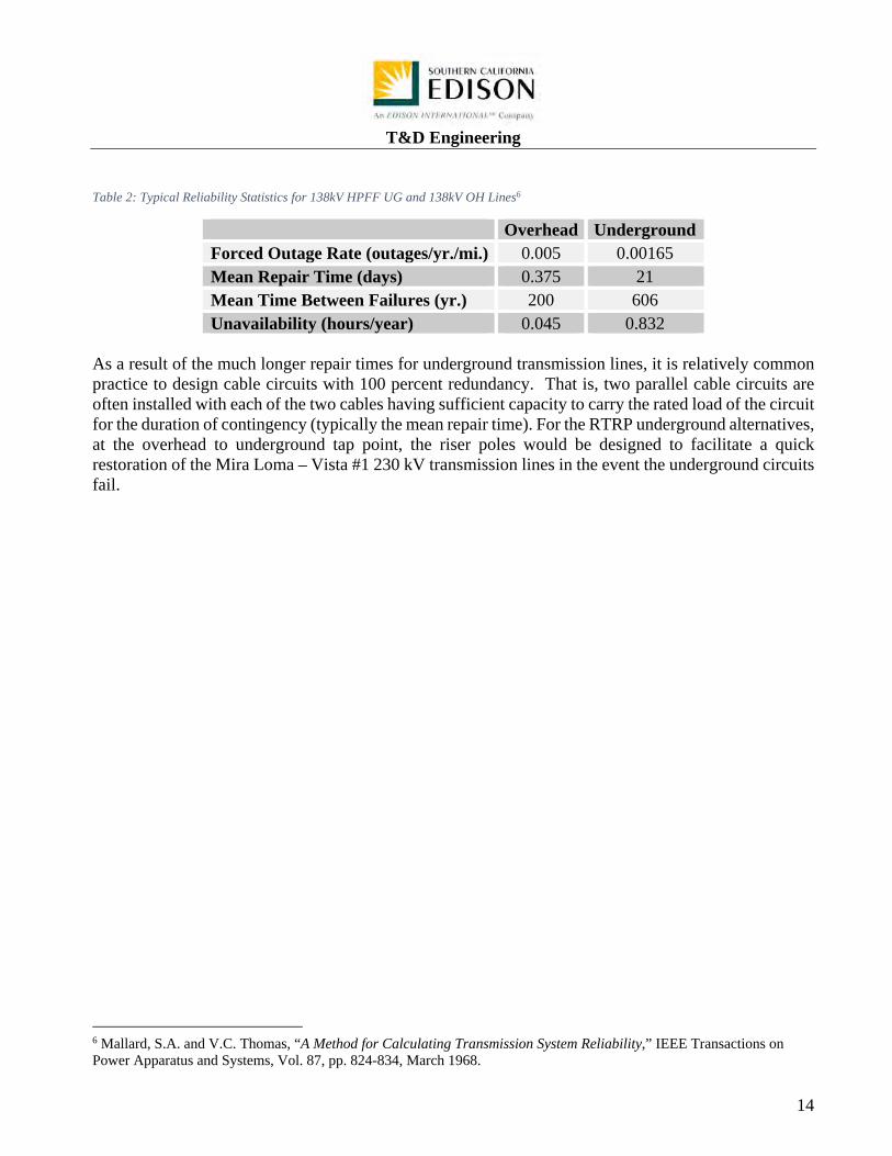
Table 2: Typical Reliability Statistics for 138kV HPFF UG and 138kV OH Lines6
Overhead Underground Forced Outage Rate (outages/yr./mi.) 0.005 0.00165 Mean Repair Time (days) 0.375 21 Mean Time Between Failures (yr.) 200 606 Unavailability (hours/year) 0.045 0.832
As a result of the much longer repair times for underground transmission lines, it is relatively common practice to design cable circuits with 100 percent redundancy. That is, two parallel cable circuits are often installed with each of the two cables having sufficient capacity to carry the rated load of the circuit for the duration of contingency (typically the mean repair time). For the RTRP underground alternatives, at the overhead to underground tap point, the riser poles would be designed to facilitate a quick restoration of the Mira Loma – Vista #1 230 kV transmission lines in the event the underground circuits fail.
6 Mallard, S.A. and V.C. Thomas, “A Method for Calculating Transmission System Reliability,” IEEE Transactions on Power Apparatus and Systems, Vol. 87, pp. 824-834, March 1968.

T&D Engineering
15
9.0 Electrical Capacity (Ampacity) Requirement The future Mira Loma-Wildlife and Vista-Wildlife 230 kV transmission lines are designed for bundled 1590 kcmil aluminum-conductor steel-reinforced (ACSR) “lapwing” conductor. The conductor thermal rating for bundled “lapwing” is 3,230 amps under normal conditions and 4,360 amps under a 4-hours emergency situation. In 66 kV and 115 kV underground transmission lines, the underground cables are required to match the thermal rating for the overhead conductor. The reason for this is that an underground transmission line will be much more difficult to upgrade later on if additional electrical capacity is needed. Generally, underground cable cannot match the ampacity of an overhead conductor of the same size. The reason for this is that the conductor of an underground cable is covered with a thick layer of insulation and placed in a duct. The heat generated from the flow of electricity is more difficult to dissipate for underground transmission lines. Because of this, for XLPE, as much as three cables per phase are required to match the ampacity of one bundled “lapwing” overhead conductor. However, the existing thermal ratings of the Mira Loma-Vista #1 230 kV transmission line are 2,300 amps under normal condition and 3,110 amps under a 4 hours emergency situation. As indicated earlier, for RTRP the Mira Loma-Vista #1 230 kV transmission line would be broken into two transmission lines, the Mira Loma-Wildlife and Vista-Wildlife 230 kV transmission lines. At a minimum, the potential underground transmission lines are required to carry the existing ratings (normal and 4-hour emergency) of the transmission line it is replacing. Besides meeting the electrical capacity of the overhead conductor, multiple cables per phase have the added benefit of increasing reliability. For example, in a two cables per phase alignment, if there is a failure, half of the circuit could potentially stay energized, providing an ampacity of 1,300 amps, while repairs are made to the other half. Furthermore, in the three cables per phase alignment, if there is a failure, 66% of the circuit could potentially stay energized, providing an ampacity of 2,600 amps, while repairs are made to the failed component. For the purpose of this evaluation, it is assumed that a two cable per phase options could meet the electrical planning requirement of the future transmission lines. Table 1 compares the thermal rating of bundled 1590 ACSR, historical rating of the current Mira Loma-Vista #1 230 kV transmission line, a three cable per phase thermal rating, and a two cable per phase thermal rating. Figure 1 shows an example of an XLPE insulated segmental copper cable with copper corrugated sheath. A typical 230 kV 5000 kcmil segmental copper cable has an approximate diameter of 5.25 inches and weigh 25 pounds per foot.

T&D Engineering
16
Figure 1: 230 kV Segmental Copper Cable with Copper Corrugated Sheath
Based on values listed in Table 3, the rating for three (3) 5000 kcmil segmental copper cable per phase is sufficient to match the thermal rating of a bundled 1590 ACSR overhead conductor. The rating for two (2) 5000 kcmil segmental copper cable per phase would be sufficient to match the planning rating of the Mira Loma – Vista #1 230 kV transmission line. Smaller conductor cable with less ampacity may be sufficient to match the planning rating but would require further study. Table 3: 230 kV Thermal Rating Comparison
Rating in Amperes Bundled 1590
ACSR (Thermal)SCE Planned
Ratings Three (3) 5000 kcmil Segmental CU/phase
Two (2) 5000 kcmil Segmental CU/phase
Normal Rating 3,230 2,300 3,900 2,600 4 Hours Emergency 4,360 3,110 5,550 3,700
The above UG ampacities are calculated with assumed soil and ambient properties, burial depth, and loading condition, and are subject to change when more accurate measurement are taken.

T&D Engineering
17
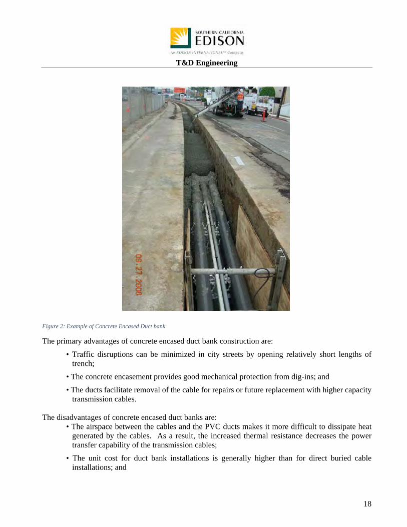
10.0 Construction Methods Because of the flat terrain of the underground routes considered here and assumed XPLE cable construction, conventional, open-trench construction is assumed to be applicable. Open-trench construction is used for the vast majority of underground transmission line installations because, as compared with trenchless construction methods, it is less complex, requires commonly available construction machinery and skills, and is less expensive in most cases. It is possible that further engineering could indicate a need for trenchless construction, but this study assumes no trenchless construction would be necessary. There are two variations of open-trench construction for underground transmission lines. These are concrete encased duct bank installation (Figure 2) and direct buried installation (Figure 3). Concrete encased duct bank are the most commonly used construction for underground transmission lines in North America. In this type of construction, a relatively short (several hundred feet) section of trench is opened, conduits are placed in the trench with plastic spacers every 10 feet to maintain conduit spacing, concrete is poured around the cable ducts, and the trench is backfilled with native soil or a special thermal backfill.
T&D Engineering
18
Figure 2: Example of Concrete Encased Duct bank
The primary advantages of concrete encased duct bank construction are:
• Traffic disruptions can be minimized in city streets by opening relatively short lengths of trench;
• The concrete encasement provides good mechanical protection from dig-ins; and
• The ducts facilitate removal of the cable for repairs or future replacement with higher capacity transmission cables.
The disadvantages of concrete encased duct banks are:
• The airspace between the cables and the PVC ducts makes it more difficult to dissipate heat generated by the cables. As a result, the increased thermal resistance decreases the power transfer capability of the transmission cables;
• The unit cost for duct bank installations is generally higher than for direct buried cable installations; and

T&D Engineering
19
• Total construction time is longer for duct bank installations compared to direct buried installations.
Figure 3: Example of Direct Buried Cable Installation
Direct buried cable installations are commonly used for most transmission cables in Europe and the Near East, but their applications in North America are usually limited to rural areas with dedicated right-of-ways. In direct buried installations, relatively long trenches are dug, the bottom of the trench filled with bedding sand, the cables are laid or pulled into the trench, and the trench is backfilled with native soil or a special thermal backfill. The primary advantages of the direct buried construction method are:
• Construction costs are lower than for concrete encased duct bank installations;
• The power transfer capability of a given cable size is higher, compared to concrete encased duct bank installations; and
• Project completion time is less than duct bank installations. The disadvantages of the direct buried construction method are:
• Cable replacement for repair or circuit uprating is not economical because excavation and reconstruction of the entire segment between vaults would be required whereas cables in duct banks can be pulled out of their conduits requiring significantly less disturbance and cost;
T&D Engineering
20
• Dedicated right-of-way is generally required; and
• Long open trenches are required but difficult to obtain in most municipalities.

T&D Engineering
21
11.0 Operation and Maintenance Impacts and Requirements According to the Association of Edison Illuminating Companies’ (AEIC) Specification for Extruded Insulation Power Cables and Their Accessories Rated Above 46kV through 345kVac (CS9-06), the projected undergrounding cable life is 40 years. This projection assumed that the various industry specifications are followed, installations are performed error free, and routine maintenance is performed on the system. This means that as the 40 year anniversary of operation approaches, an evaluation of the underground systems must be performed to determine if the cable and subsequence accessories must be replaced. Qualified electrical workers must routinely inspect the vault to ensure its structural integrity. The check ensures both integrity for the cable and safety for the general public. For example, if the vault is filled with water, the water must be pumped out. If the vault deteriorates over time, the vault could require replacement resulting in forced outages. Besides routine checks and maintenance to the vaults, SCE’s qualified electrical workers must also check on the condition of the voltage limiting arresters, grounding connection, splices, terminations, lightning arresters, and condition of the cable. From time to time, jacket integrity testing is performed on the undergrounded cable. This is accomplished by applying high DC voltage across the cable jacket for one minute. Jacket defects or damage will cause the DC Hi-Pot test set to trip out before the test voltage can be increased to 5kV. It might also be required to de-energize the circuit every few years so that a cable systems assessment could be made. In this assessment, a voltage higher than the system voltage is applied to the transmission line to find any anomalies inside the cable system. Additional operation constraints exist for an underground transmission line. One of these constraints is that the double circuit transmission lines could not be reclosed after a fault. Typically, for an overhead transmission line, SCE may reclose a circuit if the circuit breaker trips to restore power to the line. Unlike an overhead transmission line, where the fault could occur from a tree branch coming into contact with the conductor, a fault in the underground section would typically be more serious. Typically, a mode of failure for the underground circuit is either due to a dig in, splice, or termination failure. Closing the circuit breaker in this instance could cause further detrimental damages to adjacent cable, splices, terminations, and/or properties and life. Unless the fault is known to occur on the overhead section, SCE cannot restore power to this line by simply reclosing, which could result in longer forced outages.
T&D Engineering
22
12.0 Overview of the Three Underground Options for RTRP
Figure 4: Map of overhead alignment.
SCE’s T&D Engineering department was requested to analyze undergrounding a portion of a new double circuit transmission line. The portion of the RTRP transmission line being replaced consists of approximately eight lattice structures and twenty five tubular steel poles (TSP). This equates to roughly 4.5 miles of overhead construction. Structures labeled JB2 to JD25 shown in Figure 4 correspond to the overhead portion which would be replaced. Not shown in Figure 4 is the remainder of the overhead transmission line that continues to the south and east, crossing the Santa Ana River and ending at the proposed Wildlife Substation (also not shown). The transmission line would remain overhead from structure JA2/JB1 to Wildlife Substation. Figure 5 shows all three underground alternative routes superimposed on the same map for convenient reference. The three underground routes studied are shown in Appendix B.
T&D Engineering
23
Figure 5: Map of alternative underground routes.
12.1 Underground Route Alternate A – EIR UG Route This route is the longest of the three alternatives at nearly 4.5 miles long. Refer to Appendix B for an overview map of the EIR UG Route. It would consist of two trenches for the duct banks totaling approximately 48,000 ft. in length. Each trench would house an estimated six cables and three fiber cables. Each cable pull would be approximately 1,500 ft. in length and resulting in an estimated 62 splice vaults for both circuits. In total, approximately 287,000 ft. of cable (does not include contingency) would be required for this route. Common to all three route options are the requirement for an estimated 24
Wineville Route
Pats Ranch Road Route
EIR Route

T&D Engineering
24
terminations7 and 4 riser poles. For maintenance purposes, the vaults would need to be placed in an open area. Unobstructed access to these vaults shall be required at all times. The RTRP Final EIR Route follows the same alignment shown in Figure 5 and in Appendix B. The majority of the route predominately parallels the I-15 freeway. Challenges on this route include, but are not limited to grading, providing access roads, boring through freeway grade separations, avoiding freeway grade separations, as well as trenching between I-15 freeway and the Vernola Market Place. There are three major differences between this route and the RTRP Final EIR proposed overhead alignment. First, at the intersection of Bellegrave Avenue and the I-15 freeway, the underground route goes around the embankment instead of boring through it. Second, the overhead alignment is set back approximately 150 ft. south of 68th street while the underground route would go along the center of 68th street. This is due to the new housing development south of 68th street. Third, the overhead route cuts through the golf course with structures JB2, JB3, and JB4 as shown in Figure 4. Instead of following this alignment through the golf course the undergrounding would continue east on 68th street and turn south at Lucretia Avenue and continue south along the existing Mira Loma-Corona-Pedley 66 kV transmission line. The underground transmission line would then rise up approximately one quarter mile south of the intersection of 68th street and Lucretia Avenue. Table 4: Underground Alternative A Approximate Quantity Requirement
UG Alternate A – EIR Route Items Unit Approximate Quantity 5000 kcmil XLPE Cable Feet 287,000 Cable Pulling Segments Each 189 Splice Vaults Each 62 Telecom Vaults Each 31 Cable Splices Each 186 Cable Terminations Each 24 Duct bank Linear Feet 48,000 Permanent Land Disturbances Acres 6.5 Temporary Land Disturbances Acres 1.5 Total Construction Disturbances Acres 8
12.2 Underground Route Alternate B – Pats Ranch Road Route This route is most frequently referred to in protest letters as the Pats Ranch Road route. Refer to Appendix B for an overview map of the Pats Ranch Road Route.
7 A termination is a terminal component in an underground systems that provides the connection from underground cable to overhead conductor.

T&D Engineering
25
It would consist of two trenches for the duct banks totaling approximately 43,000 ft. in length. Each trench would house an estimated six cables and three fiber cables. Each cable pull would be approximately 1,500 ft. in length and resulting in an estimated 56 splice vaults for both circuits. In total, approximately 255,000 ft. of cable (does not include contingency) would be required for this route. As in the RTRP Final EIR route, an estimated 24 terminations and 4 riser poles are required. Also, for maintenance purposes, the vaults would need to be placed in an open area with unobstructed access. The Pats Ranch Road route is nearly 4.1 miles long. One end of this route begins on the northwest corner of Cantu-Galleano Ranch Road and Wineville Avenue. The route would head south on Wineville Avenue for approximately three quarters of a mile where it would turn west on Bellegrave Avenue then south on Pats Ranch Road. Currently, the portion of Pats Ranch Road north of Limonite Avenue is being constructed as part of a new housing development. Once the underground route reaches 68th street, the alignment would turn East on 68th street and continue through Goose Creek Golf Course just as in the EIR route described above. It is anticipated that most of this route would be trenched through paved road. However, the segment between limonite and Bellegrave Avenue is currently being developed. As expressed previously, there is the risk that excavation and construction activities may damage the proposed duct banks. In addition to this concern, other challenges identified on this route include trenching through paved roads and identifying existing underground utilities. This route is presents fewer technical challenges than the referenced RTRP Final EIR route, but is preliminarily thought to be less feasible than the Wineville Avenue Route described in the next section. Table 5: Underground Alternative B Approximate Quantity Requirement
UG Alternate B – Pat Ranch Route Items Unit Approximate Quantity 5000 kcmil XLPE Cable Feet 255,000 Cable Pulling Segments Each 171 Splice Vaults Each 56 Telecom Vaults Each 28 Cable Splices Each 168 Cable Terminations Each 24 Duct bank Linear Feet 43,000 Permanent Land Disturbances Acres 4.5 Temporary Land Disturbances Acres 1.5 Total Construction Disturbances Acres 6
12.3 Underground Route Alternate C – Wineville Route This is the shortest and most direct of the routes at nearly 3.6 miles. Refer to Appendix B for an overview map of the Wineville Route.

T&D Engineering
26
It would consist of two trenches for the duct banks totaling approximately 38,000 ft. in length. Each trench would house an estimated six cables and three fiber cables. Each cable pull would be approximately 1,500 ft. in length and resulting in an estimated 50 splice vaults for both circuits. In total, approximately 227,000 ft. of cable (does not include contingency) would be required for this route. As in the RTRP Final EIR route, an estimated 24 terminators and 4 riser poles are required. Also, for maintenance purposes, the vaults would need to be placed in an open area with unobstructed access. The Wineville Avenue route is predominantly on paved roads. One end of this route begins on the northwest corner of Cantu-Galleano Ranch Road and Wineville Avenue. The route continues south on Wineville Avenue for approximately 2.75 miles until it reaches 68th street. It then turns east on 68th street and continues in the same fashion as the other two routes ending at two riser poles in the golf course. Some of the challenges identified on this route include, but are not limited to trenching on paved roads and identifying underground utilities. There has been no survey of underground utilities completed. When the information on existing underground utilities becomes available, the estimated feasibility of this alternative may change. Preliminarily however, this route is estimated to present the fewest technical challenges to construction. Table 6: Underground Alternative C Approximate Quantity Requirement
UG Alternate C – Wineville Route Items Unit Approximate Quantity 5000 kcmil XLPE Cable Feet 227,000 Cable Pulling Segments Each 153 Splice Vaults Each 50 Telecom Vaults Each 25 Cable Splices Each 150 Cable Terminations Each 24 Duct bank Linear Feet 38,000 Permanent Land Disturbances Acres 4 Temporary Land Disturbances Acres 1.5 Total Construction Disturbances Acres 5.5
12.4 Requirements Common to all Underground Alternatives To achieve the required power transfer capabilities for all underground route options, the two duct banks would be spaced at least 10 ft. apart from the inside edge of the encasement. On the outside edge of the encasement, a 10 ft. separation shall be maintained from all heat sources. Because of these separations and the 4 ft. 6 in. width of the duct banks, the underground right of way would be up to approximately 50 ft. (no less than 40 ft.).
T&D Engineering
27
Thermal rating studies indicate that a bundled 230 kV 5000 kcmil segmental copper XLPE cable is sufficient to carry the planning projected amount of power for the new double circuit transmission line. Hence, six cables are estimated to be required per circuit. However, for reliability purposes, each underground circuit would be constructed in a concrete encased duct bank with three spare ducts. Each duct bank substructure would be nearly 4 ft. 6 in. wide and 3 ft. 6 in. high and have nine 8 in. schedule 40 PVC conduits. Each duct bank would also have three 5 in. schedule 40 PVC conduits for communication cables. Figure 6 illustrates this typical duct bank construction along the alignments.
Figure 6: Typical Concrete Encased Duct Bank for the Double Circuit
Underground materials (i.e. cable, splices, terminations, etc.) require extensive procurement lead times. In the event of an emergency, SCE anticipates it would be very difficult to timely acquire components necessary to make repairs. The worst case scenario would consist of an entire duct bank structure being damaged or dug up. For these reasons, replacement equipment to rebuild at least one underground span between both: (a) the longest vault to vault distance; and (b) the longest vault to riser pole section distance are needed.

T&D Engineering
28
12.5 Riser Poles For all underground route options presented here, a set of two riser poles would be installed at each end of the underground route. A riser pole is a dead-end engineered steel pole that has special attachments for connecting the underground cable to the overhead conductor. Figure 7 shows an existing set of riser pole construction similar to what would be utilized for this alternative.
Figure 7: SDG&E Transmission Riser Poles (165 ft. tall and spaced approximately 90 ft. apart)

T&D Engineering
29
SCE estimates that in the case of RTRP the riser poles that would be similar to the ones in figure 7 would require additional easement, careful sagging, and possible insulator weights. This is due to the phase spacing being over 20 feet. This spacing might create excessive line angles and blow out onto the Mira Loma-Vista #2 T/L. Typical spacing compatible with SCE hardware is 18 inches. The riser pole in Figure 7 would be adapted as shown in Figure 8 to space the conductors to at least 18 inches and mitigate some of the challenges discussed above.8 The riser pole would have an approximate height of 165 ft. and an approximate weight of 80,000 lbs.
Figure 8: Conceptual Transmission Riser Pole Modified to Bundle Overhead Conductor (see Appendix E)
At the northwest corner of Cantu-Galleano Ranch Road and Wineville Avenue, the riser poles would be spaced approximately 150 ft. apart. The westernmost riser pole would span to M1-T1 of the Mira Loma-Vista #1 230 kV T/L while the other riser pole would span to M1-T3. The southernmost circuit of M1-T2 would be undisturbed during construction and after construction it would remain vacant. This vacant position could be used to reconnect Mira Loma Substation and Vista Substation in the event of an extended outage caused by the underground portion of the line. At the other end of the underground route near the golf course, one riser pole would span to one side of the proposed lattice structure while the other riser pole would span to the other side of that same lattice structure. In total, four riser poles are estimated to be required for each underground route.
8 This study places the riser poles on existing ROW, but additional ROW may be required.

T&D Engineering
30
For 69kV and 115 kV, SCE’s construction practice is to pull the cable up inside the riser poles. However, after interviewing engineers from Pacific Gas and Electric, San Diego Gas and Electric, Los Angeles Department of Power and Water, Arizona Public Services, and various cable manufacturers, for 230 kV construction, SCE is informed that it is a common installation practice to run large diameter cable on the outside of the riser poles. A shroud made of thick sheet metal typically provides a protective barrier for the cable from the base of the riser pole up to about 30 ft. as depicted in Figure 9.
Figure 9: PG&E Riser Pole Shroud
12.6 Vaults Vaults are underground facilities that enclose cable splices. Vault locations are determined by underground cable reel size and allowable pulling tensions. For this study, vaults would be spaced in

T&D Engineering
31
approximately 1500 ft. increments. Figure 10 shows a 230 kV vault being installed for SDG&E in city streets. Similarly, figure 11 shows a SCE 500 kV vault being set into place. For the 69kV and 115 kV installation, SCE uses a 10 ft. wide by 20 ft. long by 9 ft.-6 in. high vaults. For the proposed 230 kV installation, a larger vault would most likely be required. As an example, for SCE’s 500 kV underground transmission line, a vault’s typical inside dimensions are 62 ft. long by 8 ft. wide by 8 feet. For this 230 kV alternative, the approximate inside dimensions of these vaults is estimated to be 48 ft. long by 8 ft. wide by 8 ft. tall.
Figure 10: SDG&E 230 kV Vault Installation

T&D Engineering
32
Figure 11: SCE 500 kV Vault Installation
With a vault installed, one section of the cable is pulled into the vault. There are duct openings built into the vault that allow the cable to enter. Figure 12 and Appendix F shows how the duct bank would be configured as it enters the vault. The nine polyvinyl chloride (PVC) ducts will transition from a typical duct bank and split into two vaults. Figure 13 shows an inside view of how the cables would enter a vault.
Figure 12: Duct Bank Transition
T&D Engineering
33
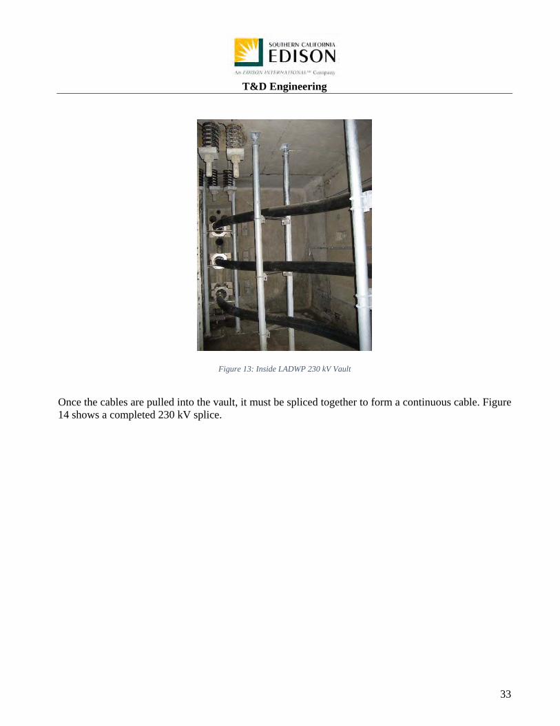
Figure 13: Inside LADWP 230 kV Vault
Once the cables are pulled into the vault, it must be spliced together to form a continuous cable. Figure 14 shows a completed 230 kV splice.

T&D Engineering
34
Figure 14: Example of a Completed 230 kV Splice
12.7 Shunt Compensation The electrical capacitance per unit length of the underground transmission line is significantly higher than the capacitance for overhead transmission lines. This is because:( a) the dielectric constant of solid insulations is several times higher than that of air and (b) ground potential for high voltage cables (the cable shield) is much closer than for overhead lines (the surface of the ground). The high capacitance of underground cables per unit of length results in the relatively high charging current requirements. The reactive mega volt-amperes (MVAR) associated with the cable charging current must either be absorbed by the power system or shunt reactors may be required at one or more locations along the cable circuits. While a system study to determine the shunt compensation requirements to support the underground portion of the line has not been performed, the 3.6 to 4.5-mile RTRP lines would likely need shunt reactive compensation to absorb capacitive charging current produced by the cables during light load periods. This assumption is based on a recent 500 kV underground project with similar length. After a study was performed, the 500 kV underground line required 346 MVAR to be installed per circuit. Because this line is a lower voltage, it was assumed that 173 MVAR, half of the requirement for the 500 kV underground line, would be installed per circuit. Most likely, the shunt reactors would be installed at Wildlife Substation. The installation of shunt reactors at Wildlife Substation would require
T&D Engineering
35
modifications to the substation’s layout and size which would be determined based upon further engineering analysis.

T&D Engineering
36
13.0 Technical Scope The following tables summarize the technical scope for each alternative analyzed in this report. Please refer to Appendix G for the civil earth work quantities. It should be noted that the limitations of this report listed in section 2 may impact the technical scope substantially. Table 7: Estimated Engineering Scope for UG EIR Route Alternative
EIR Route Alternative: Cable Installed In Encased Duct Bank and Buried Splice Vaults
Estimated Scope: Construct 4.5 miles of double circuit underground 230 kV duct bank with cable and accessories following the current EIR overhead route option.
Double Circuit Route Length (ft.) 24,000 Circuits 2Trench/Duct Bank Length (ft.) 48,000 Cables Per Phase 2
Cables Per Trench 6 Splices 186Riser Pole Height (ft.) 165 Terminations 24
Riser Pole Required 4 Splice Vaults (8' x 8' x 48' inside) 62
Cable Length w/ no Spare (ft.)
287,000 Duct bank Width (ft.) 4.5
Item Unit Quantity
Duct Bank and Structures Scope of Work ROW Prep. FT 24,000
Trench Excavation FT 48,000 Spoil Disposal CU YD 75,000
8" SCH 40 PVC Conduit FT 428,000 Clean Backfill CU YD 12,000
Fluidized Thermal Backfill CU YD 52,000 Concrete Cap Cu YD 12,000 Trench Repair SQ FT 309,000
Riser Poles EA 4 Footing for Riser Poles EA 4
Splice Vaults EA 62 Electrical Scope of Work
220 kV XLPE 5000 Segmental Cable FT 287,000 220 kV Terminations EA 24
220 kV Splices EA 186 Link Boxes EA 372
Line Arresters EA 48 Construction Supervision Weeks 124
Cable Pull Days 50 Subcontractor Installation (100 weeks) LOT 1
Field Testing & Energization LOT 1

T&D Engineering
37
Table 8: Estimated Engineering Scope for Pats Ranch Road Alternative
Pats Ranch Road Route Alternative: Cable Installed In Encased Duct Bank and Buried Splice Vaults
Estimated Scope: Construct 4.1 miles of double circuit underground 230 kV duct Bank with cable and accessories following Pats Ranch Road.
Double Circuit Route Length (ft.) 22,000 Circuits 2Trench/Duct Bank Length (ft.) 43,000 Cables Per Phase 2
Cables Per Trench 6 Splices 168Riser Pole Height (ft.) 165 Terminations 24
Riser Pole Required 4 Splice Vaults (8' x 8' x 48' inside) 56
Cable Length w/ no Spare (ft.)
255,000 Duct bank Width (ft.) 4.5
Item Unit Quantity
Duct Bank and Structures Scope of Work ROW Prep. FT 22,000
Trench Excavation FT 43,000 Spoil Disposal CU YD 66,500
8" SCH 40 PVC Conduit FT 380,500 Clean Backfill CU YD 10,500
Fluidized Thermal Backfill CU YD 46,000 Concrete Cap Cu YD 10,500 Trench Repair SQ FT 275,000
Riser Poles EA 4 Footing for Riser Poles EA 4
Splice Vaults EA 56 Electrical Scope of Work
220 kV XLPE 5000 Segmental Cable FT 255,000 220 kV Terminations EA 24
220 kV Splices EA 168 Link Boxes EA 336
Line Arresters EA 48 Construction Supervision Weeks 112
Cable Pull Days 50 Subcontractor Installation (100 weeks) LOT 1
Field Testing & Energization LOT 1

T&D Engineering
38
Table 9: Estimated Engineering Scope for Wineville Avenue Alternative
Wineville Avenue Route Alternative: Cable Installed In Encased Duct Bank and Buried Splice Vaults
Estimated Scope: Construct 3.6 miles of double circuit underground 230 kV duct bank with cable and accessories following Wineville Avenue.
Double Circuit Route Length (ft.) 19,000 Circuits 2Trench/Duct Bank Length (ft.) 38,000 Cables Per Phase 2
Cables Per Trench 6 Splices 150Riser Pole Height (ft.) 165 Terminations 24
Riser Pole Required 4 Splice Vaults (8' x 8' x 48' inside) 50
Cable Length w/ no Spare (ft.)
227,000 Duct bank Width (ft.) 4.5
Item Unit Quantity
Duct Bank and Structures Scope of Work ROW Prep. FT 19,000
Trench Excavation FT 38,000 Spoil Disposal CU YD 59,000
8" SCH 40 PVC Conduit FT 339,000 Clean Backfill CU YD 9,500
Fluidized Thermal Backfill CU YD 41,000 Concrete Cap Cu YD 9,500 Trench Repair SQ FT 245,000
Riser Poles EA 4 Footing for Riser Poles EA 4
Splice Vaults EA 50 Electrical Scope of Work
220 kV XLPE 5000 Segmental Cable FT 227,000 220 kV Terminations EA 24
220 kV Splices EA 150 Link Boxes EA 300
Line Arresters EA 48 Construction Supervision Weeks 100
Cable Pull Days 50 Subcontractor Installation (100 weeks) LOT 1
Field Testing & Energization LOT 1
T&D Engineering
39
14.0 Appendices Appendix A – Public Utilities Commission Deficiency Letter Appendix B – Underground Alternative Routes:
EIR UG Route Pats Ranch Road Route Wineville Avenue Route
Appendix C – Dismissed Underground Alternatives Appendix D – Overhead EIR Route Appendix E – RTRP Conceptual 230 kV Riser Appendix F – Duct Bank Transition Appendix G – Civil Earth Work Quantities

Appendix A
Public Utilities Commission Deficiency Letter

STATE OF CALIFORNIA
PUBLIC UTILITIES COMMISSION
505 VAN NESS AIJENUE
SAN"RANCISCO. CA 90111»03298
May 22, 201 5
Ian Forrest, Senior Attorney Southern California Edison Company Post Office Box 800 Rosemead, CA 91770 Email : [email protected]
EDMUND G. BROWN JR. . Governor
R[ : Application Deficiency - Certificate of Public Convenience and Necessity for the Riverside Transmission Reliability Project - Applicat ion No. A.J5-04-013
Dear Mr. Forrest,
The California Public Utilities Commission' s (CPUC) Energy Division CEQA Unit has completed its review of Southern Ca li fo rnia Edison's (SCE's) Application (A. 15-04-013) for a Certi ficate of Public Convenience and Necessity (CPCN) for the Riverside Transmission Reliabi lity Project (RTRP). The CPUC has also reviewed the Final Environmenta l Impact Report (EIR) prepared by the Ci ty of Riverside pursuant to the California Environmcntal Quality Act (CEQA) and the associated administrative record. The City of Riverside is the Lead Agency under CEQA, responsible for preparation of the EJR . The CPUC is a Responsible Agency under CEQA, responsible for the certifi cation of the CPCN.
City of Riverside Final EI R
The City of Ri verside certified the Final EI R for the RTRP in October 2013 and fil ed the Notice of Determinat ion on February 6, 20 13. The Final EIR certified by the City of Riverside. along with the ent ire administrative record of tile proceeding before Riverside were fi led with the Application as information equivalent to a Proponent 's Environmental Assessment.
In March 2013, Jurupa Valley filed a CEQA lawsuit in SuperiorCoUl1 challenging Ri verside's approval ofRTRP. On May 1,2014, the Los Angelcs Superior Court denied Jurupa Valley ' s chall enge and upheld the Fina l EIR and Riverside 's approval of the Project. Jurupa Valley appealed that dec ision and the appellate case is currently pending.
Changed Conditions in the Project Alignmc.nt
Subsequent to the certi fi cat ion of the EIR and approva l of the RTRP, the City of Jurupa Va lley certifi ed an Ini tial Study/ Mitigated Negati vc Declarat ion (lS/MN D) and approved the Riverbend housing project, a 466-unit subdi vision at the southeast corner of Wine ville Avenue and CantuGalleano Ranch Road. The project would be located on a 36.6-aere parcel over approximate ly I mile of the length of the proposed RTRP transmission line alignment. The approved vested tentat ive map and zoni ng and deve lopment plan for the subdi vision did not include a ri ght-ofway alignment for the RTRP route. The I>roject has bcen purchased by Lennar I-i omes, Inc. Lennar has gradcd the site and purported ly made other improvements.

Mr. Ion Forrest. Southern California Edison May 22, 2015 Page 2
In addition, the City of Jurupa Valley certified an IS/MN D and approved the Vemola Marketplace Apartments Project at the nonhwest corner of 68th Street and Pats Ranch Road in Jurupa Valley. The Notice of Detennination was filed on March 20, 201S. The project includes development of 2S apm1ment buildings, with 397 residential units, on a 17 .4~acre property. The project site is within the proposed alignment for the RTRP; the IS/MND did nol consider the RTRP and the cCfects on the proposed apartments.
The approved subdivisions with in the RTRP route are considered a substantial change in circumstances, which wi ll require the CPUC to prepare a Subsequent EIR to address new signi ficant environmental effects pursuant to CEQA Guidelines Section I S162.
Application Incomplete
After review of SeE' s application for the RTRP, the Energy Division finds thai the information contained in the Application and Final EIR is incomplete. The attached report identifies the portions of the applicat ion found 10 be deficient.
Infonnation provided by SCE in response to the Energy Division' s finding of de ficiency should be filed as supplements to Application A. I S·04~O 13. One set of responses should be sent to the Energy Division and one to our consultant Panorama Environmental, in bolh hardcopy and electronic format. We request that SCE respond to this report no later than July 21, 20 IS.
We will review the infonnation within 30 days and detennine if it is adequate to accept the application as complete. We will be avai lable to meet with you at your convenience to discuss these items.
The Energy Division reserves the right to requesl addi tional information at any point in the application proceeding and duri ng subsequent construction of the project should SeE' s CPCN be approved.
Please direct questions relaled to this application to me at (4 I S) 703~S484 or Jensen. Uch i darlVcplic . ca. gov .
Sincerely,
h dafidL-Project Manager Energy Division, CEQA Uni t
cc: AU Mary Jo Borak, Supervisor Molly Sterkel, Program Manager Jack Mull igan, CPUC Attorney Jeff Thomas, Project Manager, Panorama Environmental, Inc.
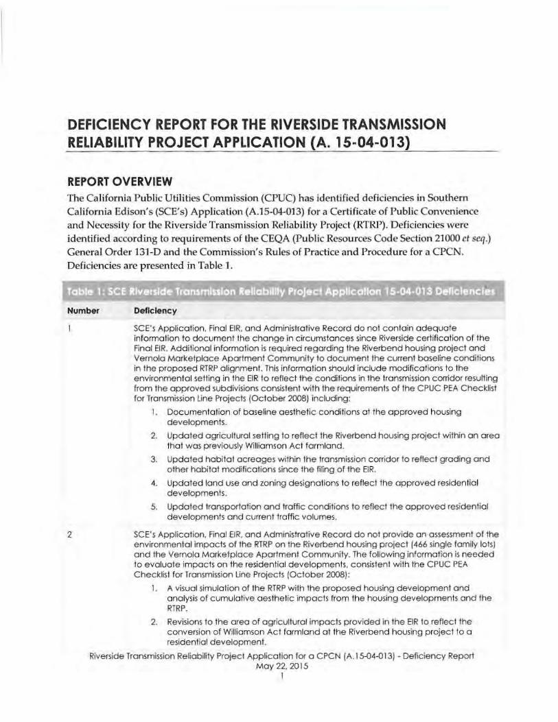
DEFICIENCY REPORT FOR THE RIVERSIDE TRANSMISSION RELIABILITY PROJECT APPLICATION (A. 15-04-013)
REPORT OVERVIEW The California Public Utilities Commission (CPUC) has identified deficiencies in Southern Ca li fo rn ia Edison's (SeE's) Application (A.1 S·04-013) for a Certi ficate of Public Convenience and Necessity for the Riverside Transmiss ion Reliability Project (RTRP) . Deficiencies were identi fied according to requirements of the CEQA (Public Resources Code Section 21000 ct seq.)
Genera l O rder 131-0 and the Commission' s Rules of Practi ce and Procedure for a CPCN. Deficiencies are presented in Table 1.
seE Riverside Transmission Reliabmly Project Application 15·04·013 Deficiencies
Number Deficiency
2
SeE's Application. Final ElR, and Administrative Record do not contoin adequate information to document the change in circumstances since Riverside certification of the Final ElR. Additional informalion is required regarding the Riverbend housing project and Vemola Mark.etplace Apartment Communily to document the current baseline conditions in the proposed RTRP alignment. This information should include modifications to the environmental selling in the EIR to reflect the conditions in the transmission corridor resulting from the approved subdivisions consistent with the requirements o f the CPUC PEA Check~st for Transmission Line Projects (October 2(08) including:
I . Documentation o f baseline aesthetic conditions at the approved housing developments.
2. Updated agriculturat selling 10 reflect the Riverbend housing project within an area fhat was previously Williamson Act farmland.
3. Updated habital ocreages within the transmission corridor to reflect grading and other habitat modifications since the filing of the EIR.
4. Updated land use and zoning designations to re flect the approved residential developments.
5. Updated transportation a nd traffic conditions fo reflect the approved residential developments and current traffic volumes.
SCE's Application, Final ElR, ond Administrative Record do not provide on assessment of the environmental impacts of the RTRP on the Riverbend housing project (466 single famity lots) and the Vemola Marketplace Apartment Community. The following information is needed to evaluate impacts on the residential developments, consistent with the CPUC PEA Check~st for Transmission line Projects (October 2008):
1. A visuol simulation o f the RTRP with the proposed housing development and analysis o f c umulative aesthetic impacts from the housing developments and the RTRP.
2. Revisions to the area of agricultural impacts provided in the EIR 10 reflec t the conversion of Williamson Act farmland at the Riverbend housing project to a residential development.
Riverside Transmission Reliabirtty Project Application for a CPCN IA.I5-04-013) • Deficiency Report May 22, 2015
1

Mr. ton Forrest, Southern California Edison May 22,2015 Page 2
Table 1- SeE Riverside Transmission Rellablilly Project ApRllcalion 15·04·013 Deflclencles
Number Deficiency
3
4
5
3. Updates to the habitat impact acreages in the EIR to reflect grading of the Riverbend project and any other changes in baseline conditions since publication of the EIR.
4. Description of hazards associated with construction and operation of the proposed project within the approved residential developments.
5. land use impacts associated with conflicts between the proposed project transmission alignment and the approved residential developments.
6. Increased noise impacts from construction within residential subdivisions and lon9-term corona noise impacts on the subdivision.
7. Impacts from construction and operation of the proposed project on transportation and traffic considering the roods that are proposed within the approved subdivisions.
B. Impacts of the proposed project on population and housing.
9. Cumulative impacts of the proposed project with other cumulative projects thaI are currenlly planned in the area.
CEQA requires consideration of ollemalives that are capable of substantialty reducing or eliminating significant environmental effects ICEQA Guidelines Section 15126.610)). Define alternatives that meet the pfOject objectives and reduce or ovoid potentially significant impacts of the proposed project on the approved Riverbend housing project and Vernela Marketp lace Apartment Community. This may include local routing alternatives or electrical system alternatives.
Provide the total volume of water that will be required for construction of the project. The City of Riverside Final ElR and response to comments state thai a maximum of 40,OCX) gallons of water would be applied per mile per day. This volume of water does not equate to a lotol volume required for the project. Specify a total maximum volume of water needed for the project and the source o f water.
Define the proposed location for disposal o f hazardous waste and trealed wood poles thai would be removed by the proposed project
Riverside Transmission Reliability Project Application lor a CPCN /A .15-04-013) - Deficiency Report May 22. 2015
2

Appendix B
Underground Alternative Routes: EIR UG Route; Pats Ranch Road Route; and Wineville Avenue Route

Path:
P:\PR
OJEC
TS\M
PO_P
roject
s\Rive
rside
Transm
ission
Relia
bility
Projec
t_WLD
\Work
ing\20
1507
20_R
TRP_
SiteR
eport
\RTRP
_Und
ergrou
ndRo
utesE
valua
ted_2
0150
723.m
xd
Notification #: 201864893Date: 7/23/2015
File Name: RTRP_UndergroundRoutesEvaluated_20150723.mxdVersion #: 01
I0 770 1,540385
Feet
1 in = 1,314 feet
Features depicted herein are planning level accuracy, and intendedfor informational purposes only. Distances and locations may bedistorted at this scale. Always consult with the proper legaldocuments or agencies regarding such features. Real PropertiesDepartmentThomas Bros. Maps is a registered trademark of Rand McNally &Company.Reproduced with permission granted by Rand McNally & Company.© Rand McNally & Company. All rights reserved.Service Layer Credits: Image courtesy of USGS © 2015 MicrosoftCorporation © 2015 HERE © ANDContent may not reflect National Geographic's current map policy.Sources: National Geographic, Esri, DeLorme, HERE, UNEP-WCMC,
RTRP Underground Routes Evaluated Overview Map
"/ Riser
EIR Route (Modified 68th St)
Pats Ranch Road Route
Wineville Avenue Route
Page 2 Page 3
Page 4
Page 5
Page 7

Appendix C
Dismissed Underground Alternatives

Path:
P:\PR
OJEC
TS\M
PO_P
roject
s\Rive
rside
Transm
ission
Relia
bility
Projec
t_WLD
\Work
ing\20
1507
20_R
TRP_
SiteR
eport
\RTRP
_Van
B_Ba
in_UG
_v02
_201
5071
7.mxd
RTRP Underground 220 kV Alternative Routes DismissedBain Street and Van Buren Boulevard
Notification #: 201864893Date: 7/23/2015
File Name: RTRP_VanB_Bain_UG_v02_20150717.mxdVersion #: 1
I0 1,300 2,600650
Feet
1 in = 2,366 feetFeatures depicted herein are planning level accuracy, andintended for informational purposes only. Distances andlocations may be distorted at this scale. Always consult withthe proper legal documents or agencies regarding suchfeatures. Real Properties Department Thomas Bros. Maps isa registered trademark of Rand McNally &Company.Reproduced with permission granted by RandMcNally & Company. © Rand McNally & Company. All rightsreserved. Service Layer Credits: Image courtesy of USGS ©2015 Microsoft Corporation © 2015 HERE © ANDContent may not reflect National Geographic's current mappolicy. Sources: National Geographic, Esri, DeLorme, HERE,UNEP-WCMC, USGS, NASA, ESA, METI, NRCAN, GEBCO,NOAA, increment P Corp.
Final EIR Overhead Route (For reference)
Van Buren Underground Route Alternative
Bain Underground Route Alternative
Limonite Ave
Van Buren Blvd
Bain St
Jurupa RdBellegrave Ave
Van Buren Blvd
Wineville Ave
Limonite Ave
Cantu-Galleano Ranch Rd
68th St

Appendix D
Overhead EIR Route

City of Riverside Chapter 2. Proposed Project Description
DRAFT ENVIRONMENTAL IMPACT REPORT OCTOBER 2012RIVERSIDE TRANSMISSION RELIABILITY PROJECT 2-15
ANA 032-126 (PER-02) RPU (October 2012) SB 124462/124464
FIGURE 2.3-3. PROPOSED 230 KV TRANSMISSION LINE (REVISED)
06062

Appendix E
RTRP Conceptual 230 kV Riser


Appendix F
Duct Bank Transition


Appendix G
Civil Earth Work Quantities

RTRP Underground Alternatives Civil Engineering Quantity EstimatePrepared on: 07/22/2015
EIR ROUTE WINEVILLE-PATS ROAD WINEVILLE OVERHEAD PORTION
Duct Excavation 52,000 CY 46,000 CY 41,000 CY 0 CY
Vault Excavation 22,100 CY 20,000 CY 18,000 CY 0 CY
Manhole Excavation 600 CY 500 CY 500 CY 0 CY
Over-Ex and Recompact 8,000 CY 7,100 CY 6,300 CY 0 CY
Thermal Backfill 52,000 CY 46,000 CY 41,000 CY 0 CY
Undergro
und Exc
avat
ion
Ap
pen
dix G
- Civil Earth
Wo
rk Qu
antities
Asphalt - 4" Thickness 64,500 SQ FT 192,000 SQ FT 164,000 SQ FT 0 SQ FT
Class II Base - 6" Thickness 64,500 SQ FT 192,000 SQ FT 164,000 SQ FT 0 SQ FT
Over-Ex and Recompact - 12"
Thickness64,500 SQ FT 192,000 SQ FT 164,000 SQ FT 0 SQ FT
Paved R
oads
Ap
pen
dix G
- Civil Earth
Wo
rk Qu
antities
Length of Access Road 15,000 LFT 0 LFT 0 LFT 19,000 LFT
Cut 2,500 CY 0 CY 0 CY 2,500 CY
Fill 2,500 CY 0 CY 0 CY 2,500 CY
Over-Ex and Recompact 8,500 CY 0 CY 0 CY 11,000 CY
Export 0 CY 0 CY 0 CY 0 CY
Import 0 CY 0 CY 0 CY 0 CY
Transm
issio
n Acc
ess R
oads
Ap
pen
dix G
- Civil Earth
Wo
rk Qu
antities
Permanent Land Disturbance 6.5 AC 4.5 AC 4 AC 2 AC
Temporary Land Disturbance 1.5 AC 1.5 AC 1.5 AC 6.5 AC
Total Land Disturbance 8 AC 6 AC 5.5 AC 8.5 AC
Note: Estimated values are based on preliminary evaluations and are subject to change based on confirmed field conditions and final engineering. The presence of
existing underground utilities would likely impact the technical and environmental challenges associated with each undergrounding alternative
Land D
isturb
ance
Appendix G - Civil Earth Work Quantities