Embed Size (px)
Citation preview

OptiX RTN 950A Radio Transmission SystemV100R005C01
Product Description
Issue 01
Date 2012-12-15
HUAWEI TECHNOLOGIES CO., LTD.
Copyright © Huawei Technologies Co., Ltd. 2012. All rights reserved.No part of this document may be reproduced or transmitted in any form or by any means without prior writtenconsent of Huawei Technologies Co., Ltd. Trademarks and Permissions
and other Huawei trademarks are trademarks of Huawei Technologies Co., Ltd.All other trademarks and trade names mentioned in this document are the property of their respective holders. NoticeThe purchased products, services and features are stipulated by the contract made between Huawei and thecustomer. All or part of the products, services and features described in this document may not be within thepurchase scope or the usage scope. Unless otherwise specified in the contract, all statements, information,and recommendations in this document are provided "AS IS" without warranties, guarantees or representationsof any kind, either express or implied.
The information in this document is subject to change without notice. Every effort has been made in thepreparation of this document to ensure accuracy of the contents, but all statements, information, andrecommendations in this document do not constitute a warranty of any kind, express or implied.
Huawei Technologies Co., Ltd.Address: Huawei Industrial Base
Bantian, LonggangShenzhen 518129People's Republic of China
Website: http://www.huawei.com
Email: [email protected]
Issue 01 (2012-12-15) Huawei Proprietary and ConfidentialCopyright © Huawei Technologies Co., Ltd.
i

About This Document
Related VersionsThe following table lists the product versions related to this document.
Product Name Version
OptiX RTN 950A V100R005C01
iManager U2000 V100R008C00
Intended AudienceThis document is intended for network planning engineers.
Familiarity with the basic knowledge related to digital microwave communication technologywill help you apply the information in this document.
Symbol ConventionsThe symbols that may be found in this document are defined as follows.
Symbol Description
Indicates a hazard with a high level of risk,which if not avoided, will result in death orserious injury.
Indicates a hazard with a medium or low levelof risk, which if not avoided, could result inminor or moderate injury.
OptiX RTN 950A Radio Transmission SystemProduct Description About This Document
Issue 01 (2012-12-15) Huawei Proprietary and ConfidentialCopyright © Huawei Technologies Co., Ltd.
ii

Symbol Description
Indicates a potentially hazardous situation,which if not avoided, could result inequipment damage, data loss, performancedegradation, or unexpected results.
Indicates a tip that may help you solve aproblem or save time.
Provides additional information to emphasizeor supplement important points of the maintext.
General ConventionsThe general conventions that may be found in this document are defined as follows.
Convention Description
Times New Roman Normal paragraphs are in Times New Roman.
Boldface Names of files, directories, folders, and users are inboldface. For example, log in as user root.
Italic Book titles are in italics.
Courier New Examples of information displayed on the screen are inCourier New.
Update HistoryUpdates between document issues are cumulative. Therefore, the latest document issue containsall updates made in previous issues.
Updates in Issue 01 (2012-12-15) Based on Product Version V100R005C01This document is the first release for the V100R005C01 product version.
OptiX RTN 950A Radio Transmission SystemProduct Description About This Document
Issue 01 (2012-12-15) Huawei Proprietary and ConfidentialCopyright © Huawei Technologies Co., Ltd.
iii

Contents
About This Document.....................................................................................................................ii
1 Introduction....................................................................................................................................11.1 Network Application..........................................................................................................................................21.2 Components........................................................................................................................................................31.3 Radio Link Types...............................................................................................................................................7
2 Functions and Features.................................................................................................................82.1 Microwave Types.............................................................................................................................................10
2.1.1 SDH Microwave......................................................................................................................................102.1.2 Hybrid/Packet Integrated IP Microwave.................................................................................................10
2.2 Modulation Strategy.........................................................................................................................................122.2.1 Fixed Modulation....................................................................................................................................132.2.2 Adaptive Modulation...............................................................................................................................13
2.3 RF Configuration Modes..................................................................................................................................152.4 Capacity............................................................................................................................................................16
2.4.1 Air Interface Capacity.............................................................................................................................162.4.2 Cross-Connect Capacity..........................................................................................................................172.4.3 Switching Capacity..................................................................................................................................17
2.5 Interfaces..........................................................................................................................................................172.5.1 Service Interfaces....................................................................................................................................172.5.2 Management and Auxiliary Interfaces.....................................................................................................19
2.6 Cross-Polarization Interference Cancellation...................................................................................................212.7 Automatic Transmit Power Control.................................................................................................................222.8 MPLS/PWE3 Function.....................................................................................................................................222.9 Ethernet Service Processing Capability............................................................................................................242.10 QoS.................................................................................................................................................................262.11 Clock Features................................................................................................................................................272.12 Protection Capability......................................................................................................................................292.13 Network Management....................................................................................................................................302.14 Easy Installation.............................................................................................................................................312.15 Easy Maintenance...........................................................................................................................................32
2.15.1 Equipment-level OAM..........................................................................................................................322.15.2 Packet Services OAM (TP-Assist)........................................................................................................33
OptiX RTN 950A Radio Transmission SystemProduct Description Contents
Issue 01 (2012-12-15) Huawei Proprietary and ConfidentialCopyright © Huawei Technologies Co., Ltd.
iv

2.16 Security Management.....................................................................................................................................352.17 Energy Saving.................................................................................................................................................372.18 Environmental Protection...............................................................................................................................37
3 Product Structure.........................................................................................................................393.1 System Architecture.........................................................................................................................................403.2 Hardware Structure...........................................................................................................................................41
3.2.1 IDU..........................................................................................................................................................413.2.2 ODU.........................................................................................................................................................45
3.3 Software Structure............................................................................................................................................473.4 Service Signal Processing Flow.......................................................................................................................48
3.4.1 SDH Microwave......................................................................................................................................483.4.2 Hybrid Microwave...................................................................................................................................503.4.3 Packet Microwave...................................................................................................................................53
4 Networking and Applications..................................................................................................564.1 Basic Network Topologies...............................................................................................................................57
4.1.1 Chain Network.........................................................................................................................................574.1.2 Ring Network..........................................................................................................................................57
4.2 Networking with the OptiX RTN 310..............................................................................................................584.3 Feature Application (MPLS Packet Service)....................................................................................................59
4.3.1 CES Services...........................................................................................................................................594.3.2 ATM/IMA Services.................................................................................................................................634.3.3 Ethernet Services.....................................................................................................................................64
4.4 Feature Application (Traversing the Original Network)..................................................................................664.4.1 Traversing a TDM Network by Using the EoPDH/EoSDH Feature.......................................................664.4.2 Using ML-PPP to Transmit Services Through a TDM Network............................................................674.4.3 Traversing a Layer 2 Network by Using VLAN Sub-interfaces.............................................................68
5 Network Management System..................................................................................................705.1 Network Management Solution........................................................................................................................715.2 Web LCT..........................................................................................................................................................715.3 U2000...............................................................................................................................................................73
6 Technical Specifications.............................................................................................................766.1 RF Performance................................................................................................................................................77
6.1.1 Microwave Work Modes.........................................................................................................................776.1.1.1 Microwave Work Modes (IFU2 board)..........................................................................................776.1.1.2 Microwave Work Modes (ISU2 board)..........................................................................................786.1.1.3 Microwave Work Modes (ISX2 board)..........................................................................................816.1.1.4 Microwave Work Modes (ISV3 Board).........................................................................................86
6.1.2 Frequency Band.......................................................................................................................................956.1.3 Receiver Sensitivity.................................................................................................................................98
6.1.3.1 Receiver Sensitivity (IFU2 board)..................................................................................................986.1.3.2 Receiver Sensitivity (ISU2 board)................................................................................................101
OptiX RTN 950A Radio Transmission SystemProduct Description Contents
Issue 01 (2012-12-15) Huawei Proprietary and ConfidentialCopyright © Huawei Technologies Co., Ltd.
v

6.1.3.3 Receiver Sensitivity (ISX2 board)................................................................................................1076.1.3.4 Receiver Sensitivity (ISV3 board)................................................................................................117
6.1.4 Distortion Sensitivity.............................................................................................................................1286.1.5 Transceiver Performance.......................................................................................................................1296.1.6 IF Performance......................................................................................................................................1356.1.7 Baseband Signal Processing Performance of the Modem.....................................................................136
6.2 Predicted Equipment Reliability.....................................................................................................................1366.2.1 Predicted Component Reliability...........................................................................................................1366.2.2 Predicted Link Reliability......................................................................................................................137
6.3 Interface Performance.....................................................................................................................................1376.3.1 SDH Interface Performance...................................................................................................................1376.3.2 E1 Interface Performance......................................................................................................................1396.3.3 Ethernet Interface Performance.............................................................................................................1406.3.4 Auxiliary Interface Performance...........................................................................................................144
6.4 Clock Timing and Synchronization Performance..........................................................................................1456.5 Integrated System Performance......................................................................................................................146
A Typical Configuration.............................................................................................................149A.1 Typical RF Configuration Modes..................................................................................................................150
B Compliance Standards.............................................................................................................151B.1 ITU-R Standards............................................................................................................................................152B.2 ETSI Standards..............................................................................................................................................153B.3 IEC Standards................................................................................................................................................154B.4 ITU-T Standards............................................................................................................................................155B.5 IETF Standards..............................................................................................................................................158B.6 IEEE Standards..............................................................................................................................................161B.7 MEF Standards...............................................................................................................................................161B.8 AF Standards..................................................................................................................................................162B.9 Environmental Standards...............................................................................................................................162
C Glossary......................................................................................................................................166
OptiX RTN 950A Radio Transmission SystemProduct Description Contents
Issue 01 (2012-12-15) Huawei Proprietary and ConfidentialCopyright © Huawei Technologies Co., Ltd.
vi

1 Introduction
About This Chapter
The OptiX RTN 950A is a product in the OptiX RTN 900 radio transmission system series.
1.1 Network ApplicationThe OptiX RTN 900 is a new generation TDM/Hybrid/Packet integrated microwavetransmission system developed by Huawei. It provides a seamless microwave transmissionsolution for mobile communication network or private networks.
1.2 ComponentsThe OptiX RTN 950A adopts a split structure. The system consists of the IDU 950A and theODU. Each ODU is connected to the IDU 950A through an IF cable.
1.3 Radio Link TypesThe OptiX RTN 950A provides the radio links of various types in which different IF boards andODUs are configured for diverse microwave application scenarios.
OptiX RTN 950A Radio Transmission SystemProduct Description 1 Introduction
Issue 01 (2012-12-15) Huawei Proprietary and ConfidentialCopyright © Huawei Technologies Co., Ltd.
1

1.1 Network ApplicationThe OptiX RTN 900 is a new generation TDM/Hybrid/Packet integrated microwavetransmission system developed by Huawei. It provides a seamless microwave transmissionsolution for mobile communication network or private networks.
OptiX RTN 900 Product FamilyThere are five types of OptiX RTN 900 V100R005C01 products: OptiX RTN 905, OptiX RTN910, OptiX RTN 950, OptiX RTN 950A, and OptiX RTN 980. Users can choose the productbest suited for their site.l The IDU of the OptiX RTN 905 is 1U high, integrated and case-shaped. The OptiX RTN
905 supports various types of IDUs (different in port type, IF port count, and scalability).l The IDU of the OptiX RTN 910 is 1U high and supports one or two IF boards and various
service interface boards. The OptiX RTN 910 provides various service interface boardsand integrates service ports on its system control, switching, and timing board.
l The IDU of the OptiX RTN 950 is 2U high and supports one to six IF boards and variousservice interface boards. The OptiX RTN 950 provides various service interface boards.
l The IDU of the OptiX RTN 950A is 2U high and supports one to six IF boards and variousservice interface boards. The OptiX RTN 950A provides various service interface boardsand integrates service ports on its system control, switching, and timing board.
l The IDU of the OptiX RTN 980 is 5U high and supports one to fourteen IF boards. TheOptiX RTN 980 provides various service interface boards and integrates service ports onits system control, switching, and timing board.
The OptiX RTN 900 series provide a variety of service interfaces and can be installed easily andconfigured flexibly. The OptiX RTN 900 series provide a solution that can integrate TDMmicrowave, Hybrid microwave, and Packet microwave technologies according to thenetworking scheme for the sites, achieving smooth upgrade from TDM microwave to Hybridmicrowave, and from Hybrid microwave to Packet microwave. This solution meets thetransmission requirements of 2G, 3G, and LTE services while also allowing for future networkevolution and convergence.
NOTE
OptiX RTN 900 series products can construct a network with each other and can be interconnected whenhousing applicable IF boards. To be specific, the OptiX RTN 910/950/950A/980 integrates TDM, Hybrid,and Packet microwave on one platform. The OptiX RTN 905 can simultaneously transmit Native TDM,Native Ethernet, and ETH PWE3 services.
OptiX RTN 950AThe OptiX RTN 950A is deployed at the access and convergence layers. Figure 1-1 shows themicrowave transmission solution provided by the OptiX RTN 950A.
OptiX RTN 950A Radio Transmission SystemProduct Description 1 Introduction
Issue 01 (2012-12-15) Huawei Proprietary and ConfidentialCopyright © Huawei Technologies Co., Ltd.
2

Figure 1-1 Microwave transmission solution provided by the OptiX RTN 950A
OptiX RTN 950A BTSNodeB BSCRNC
FEE1
FEE1
E1
E1FE
E1
E1
FE
FE/GE
E1/STM-1
Regional TDMNetwork
E1/STM-1
FE/GE
FE/GE
Regional PacketNetwork
MSTP
NOTE
l In this solution, the OptiX RTN 950A is connected to an RNC and BSC directly or through a regionalbackhaul network.
l The OptiX RTN 950A provides a wide range of interfaces and service bearer technologies to adapt to theregional backhaul network. The regional backhaul network can be a time-division multiplexing (TDM)network or packet switching network (PSN).
l The OptiX RTN 950A supports the Ethernet over SDH (EoSDH) function, Ethernet over PDH (EoPDH)function, and ML-PPP function. Therefore, packet services can be backhauled through a TDM network.
l The OptiX RTN 950A supports the pseudo wire emulation edge-to-edge (PWE3) technology. Therefore,TDM, ATM, and Ethernet services can be backhauled through a PSN.
l The OptiX RTN 950A supports the VLAN sub-interface function. Therefore, MPLS packet services canbe backhauled through a Layer 2 network.
1.2 ComponentsThe OptiX RTN 950A adopts a split structure. The system consists of the IDU 950A and theODU. Each ODU is connected to the IDU 950A through an IF cable.
IDU 950AThe IDU 950A is the indoor unit for an OptiX RTN 950A system. It receives and multiplexesservices, performs service processing and IF processing, and provides the system control andcommunications function.
Table 1-1 lists the basic features of the IDU 950A.
OptiX RTN 950A Radio Transmission SystemProduct Description 1 Introduction
Issue 01 (2012-12-15) Huawei Proprietary and ConfidentialCopyright © Huawei Technologies Co., Ltd.
3

Table 1-1 Features of the IDU 950A
Item Description
Chassis height 2U
Pluggable Supported
Number of radio directions 1 to 6
RF configuration mode l 1+0 non-protection configurationl N+0 non-protection configuration (N ≤ 6)l 1+1 protection configurationl N+1 protection configuration (N ≤ 5)l XPIC configuration
Service interface type l E1 interfacel STM-1 optical/electrical interfacel FE optical/electrical interfacel GE optical/electrical interface
Figure 1-2 Appearance of the IDU 950A
ODUThe ODU is the outdoor unit for the OptiX RTN 900. It converts frequencies and amplifiessignals.
The OptiX RTN 900 product series can use the RTN 600 ODU and RTN XMC ODU, coveringthe entire frequency band from 6 GHz to 42 GHz.
NOTE
Unlike the other frequency bands that use 14 MHz, 28 MHz, or 56 MHz channel spacing, the 18 GHzfrequency band uses 13.75 MHz, 27.5 MHz, or 55 MHz channel spacing.
OptiX RTN 950A Radio Transmission SystemProduct Description 1 Introduction
Issue 01 (2012-12-15) Huawei Proprietary and ConfidentialCopyright © Huawei Technologies Co., Ltd.
4

Table 1-2 RTN XMC ODUs that the OptiX RTN 950A supports
Item Description
High-Power ODU Low CapacityODU
ODU type XMC-2 XMC-1
Frequency band 6/7/8/11/13/15/18/23/26/28/32/38/42 GHz 7/8/11/13/15/18/23GHz
Microwavemodulation scheme
QPSK/16QAM/32QAM/64QAM/128QAM/256QAM/512QAM/1024QAM(6/11/13/15/18/23/26/28/32/38/42 GHz)QPSK/16QAM/32QAM/64QAM/128QAM/256QAM (7/8 GHz)
QPSK/16QAM
Channel spacing 7/14/28/40/50/56 MHz 3.5/7/14/28 MHz
Table 1-3 RTN 600 ODUs that the OptiX RTN 950A supports
Item Description
High-Power ODU Standard Power ODU
ODU type HP, HPA SP, SPA
Frequency band 6/7/8/10/10.5/11/13/15/18/23/26/28/32/38 GHz (HP)6/7/8/11/13/15/18/23 GHz(HPA)
7/8/11/13/15/18/23/26/38GHz (SP ODU)6/7/8/11/13/15/18/23 GHz(SPA ODU)
Microwave modulationscheme
QPSK/16QAM/32QAM/64QAM/128QAM/256QAM
QPSK/16QAM/32QAM/64QAM/128QAM/256QAM
Channel spacing 7/14/28/40/56 MHz(6/7/8/10/11/13/15/18/23/26/28/32/38 GHz)7/14/28 MHz (10.5 GHz)
3.5/7/14/28 MHz
There are two methods for mounting the ODU and the antenna: direct mounting and separatemounting.
l The direct mounting method is generally adopted when a small- or medium-diameter andsingle-polarized antenna is used. In this situation, if one ODU is configured for one antenna,the ODU is directly mounted at the back of the antenna. If two ODUs are configured forone antenna, an RF signal combiner/splitter (hence referred to as a hybrid coupler) mustbe mounted to connect the ODUs to the antenna. Figure 1-3 illustrates the direct mountingmethod.The direct mounting method can also be adopted when a small- or medium-diameter anddual-polarized antenna is used. Two ODUs are mounted onto an antenna using an
OptiX RTN 950A Radio Transmission SystemProduct Description 1 Introduction
Issue 01 (2012-12-15) Huawei Proprietary and ConfidentialCopyright © Huawei Technologies Co., Ltd.
5

orthomode transducer (OMT). The method for installing an OMT is similar to that forinstalling a hybrid coupler.
Figure 1-3 Direct mounting
l The separate mounting method is adopted when a large- or medium-diameter and single-
or dual-polarized antenna is used. Figure 1-4 shows the separate mounting method. In thissituation, a hybrid coupler can be mounted (two ODUs share one feed boom).
Figure 1-4 Separate mounting
NOTE
The OptiX RTN 950A provides an antenna solution that covers the entire frequency band, and supportssingle-polarized antennas and dual-polarized antennas with diameters of 0.3 m to 3.7 m along with thecorresponding feeder system.
OptiX RTN 950A Radio Transmission SystemProduct Description 1 Introduction
Issue 01 (2012-12-15) Huawei Proprietary and ConfidentialCopyright © Huawei Technologies Co., Ltd.
6

1.3 Radio Link TypesThe OptiX RTN 950A provides the radio links of various types in which different IF boards andODUs are configured for diverse microwave application scenarios.
Table 1-4 Radio link types that the OptiX RTN 950A supports
Radio Link Type System Control,Switching, andTiming Board
IF Board ODU
High-capacity SDHmicrowave
CSHO ISU2ISV3
Standard powerODU or high powerODU
High-capacity SDHmicrowavesupporting XPIC
CSHO ISX2ISV3
Standard powerODU or high powerODU
Integrated IPmicrowave
CSHO IFU2ISU2ISV3
Standard powerODU or high powerODU
Integrated IPmicrowavesupporting XPIC
CSHO ISX2ISV3
Standard powerODU or high powerODU
OptiX RTN 950A Radio Transmission SystemProduct Description 1 Introduction
Issue 01 (2012-12-15) Huawei Proprietary and ConfidentialCopyright © Huawei Technologies Co., Ltd.
7

2 Functions and Features
About This Chapter
The OptiX RTN 950A provides a wide assortment of functions and features to ensure the qualityand efficiency of service transmission.
2.1 Microwave TypesThe microwave type is determined by the IF board and the configured working mode.
2.2 Modulation StrategyThe SDH/PDH microwave supports fixed modulation. The Hybrid/Packet microwave supportsfixed modulation and adaptive modulation.
2.3 RF Configuration Modes1+0 non-protection configuration, N+0 non-protection configuration, 1+1 protectionconfiguration, N+1 protection configuration, and XPIC configuration. The
2.4 CapacityThe OptiX RTN 950A is a high-capacity device.
2.5 InterfacesThe OptiX RTN 950A provides a variety of interfaces.
2.6 Cross-Polarization Interference CancellationCross-polarization interference cancellation (XPIC) technology is used together with co-channeldual-polarization (CCDP). The application of the two technologies doubles the wireless linkcapacity over the same channel.
2.7 Automatic Transmit Power ControlAutomatic transmit power control (ATPC) enables the output power of the transmitter toautomatically trace the level fluctuation at the receive end within the ATPC control range. Thisfeature reduces the interference with neighboring systems and residual BER.
2.8 MPLS/PWE3 FunctionThe OptiX RTN 950A uses an MPLS that is optimized for the telecom bearer network as thepacket forwarding mechanism for packet transmission of carrier-class services. The OptiX RTN950A uses PWE3 technology as the service bearer technology to implement MPLS networkaccess for various types of services.
2.9 Ethernet Service Processing Capability
OptiX RTN 950A Radio Transmission SystemProduct Description 2 Functions and Features
Issue 01 (2012-12-15) Huawei Proprietary and ConfidentialCopyright © Huawei Technologies Co., Ltd.
8

The OptiX RTN 950A has powerful Ethernet service processing capability.
2.10 QoSThe OptiX RTN 950A provides improved quality of service (QoS) and supports the followingeight types of per-hop behaviors (PHBs): BE, AF1, AF2, AF3, AF4, EF, CS6, and CS7.Therefore, network carriers can offer various QoS levels of service guarantees and buildnetworks that carry data, voice, and video services.
2.11 Clock FeaturesThe OptiX RTN 950A supports physical-layer clock synchronization, time synchronization overpacket networks, and IEEE 1588v2 time synchronization, meeting the clock and timesynchronization requirements of mobile networks. In addition, the OptiX RTN 950A providesan advanced clock protection mechanism.
2.12 Protection CapabilityThe OptiX RTN 950A provides a variety of protection schemes.
2.13 Network ManagementThe OptiX RTN 950A supports multiple network management (NM) modes and providescomprehensive NM information exchange schemes.
2.14 Easy InstallationThe OptiX RTN 950A supports several installation modes. That is, the installation is flexibleand convenient.
2.15 Easy MaintenanceThe OptiX RTN 950A provides plentiful maintenance features.
2.16 Security ManagementThe OptiX RTN 950A can prevent unauthorized logins and operations, ensuring equipmentmanagement security.
2.17 Energy SavingThe OptiX RTN 950A uses various types of technologies to reduce the amount of energy thatthe device consumes. The device:
2.18 Environmental ProtectionThe OptiX RTN 950A is designed to meet or exceed environmental protection requirements.The product complies with the RoHS directive and WEEE directive.
OptiX RTN 950A Radio Transmission SystemProduct Description 2 Functions and Features
Issue 01 (2012-12-15) Huawei Proprietary and ConfidentialCopyright © Huawei Technologies Co., Ltd.
9
2.1 Microwave TypesThe microwave type is determined by the IF board and the configured working mode.
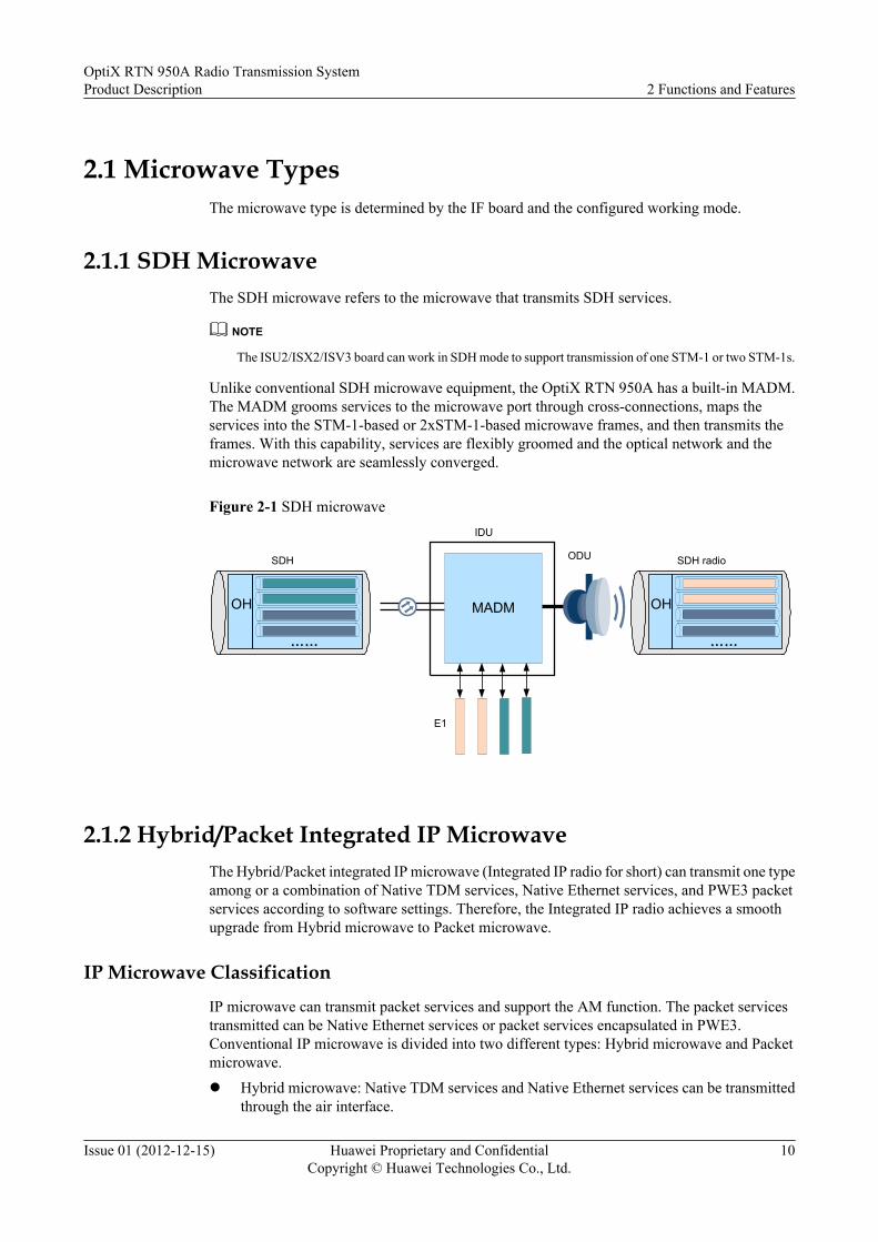
2.1.1 SDH MicrowaveThe SDH microwave refers to the microwave that transmits SDH services.
NOTE
The ISU2/ISX2/ISV3 board can work in SDH mode to support transmission of one STM-1 or two STM-1s.
Unlike conventional SDH microwave equipment, the OptiX RTN 950A has a built-in MADM.The MADM grooms services to the microwave port through cross-connections, maps theservices into the STM-1-based or 2xSTM-1-based microwave frames, and then transmits theframes. With this capability, services are flexibly groomed and the optical network and themicrowave network are seamlessly converged.
Figure 2-1 SDH microwave
ODU
E1
IDU
MADM
SDH radioSDH
OH
……
OH
……
2.1.2 Hybrid/Packet Integrated IP MicrowaveThe Hybrid/Packet integrated IP microwave (Integrated IP radio for short) can transmit one typeamong or a combination of Native TDM services, Native Ethernet services, and PWE3 packetservices according to software settings. Therefore, the Integrated IP radio achieves a smoothupgrade from Hybrid microwave to Packet microwave.
IP Microwave Classification
IP microwave can transmit packet services and support the AM function. The packet servicestransmitted can be Native Ethernet services or packet services encapsulated in PWE3.Conventional IP microwave is divided into two different types: Hybrid microwave and Packetmicrowave.l Hybrid microwave: Native TDM services and Native Ethernet services can be transmitted
through the air interface.
OptiX RTN 950A Radio Transmission SystemProduct Description 2 Functions and Features
Issue 01 (2012-12-15) Huawei Proprietary and ConfidentialCopyright © Huawei Technologies Co., Ltd.
10

l Packet microwave: TDM services, ATM/IMA services, and Ethernet services after PWE3encapsulation are transmitted through the air interface.
As IP microwave evolves, the OptiX RTN 950A supports Integrated IP radio. As a result, theequipment can support Hybrid microwave and Packet microwave at the same time, and cansimultaneously transmit multiple types of services at air interfaces.
NOTE
The IFU2, ISU2, ISX2, and ISV3 boards support Integrated IP radio.
Integrated IP radioTo achieve flexible grooming of TDM services and packet services on the Integrated IP radio,the OptiX RTN 950A is embedded with dual service planes: TDM service processing plane andpacket service processing plane. TDM services and packet services can be flexibly transmittedover the Integrated IP radio, as shown in Figure 2-2.
l TDM service processing planePerforms cross-connections on the incoming TDM services (E1 services or STM-1services), and transmits the services to the microwave ports.
l Packet service processing planePerforms PWE3 emulation on the incoming services (E1 services, ATM/IMA services, andEthernet services), encapsulates them into the MPLS packets, and transmits the Ethernetframes that bear the MPLS packets to the microwave ports. Ethernet services are directlytransmitted to the microwave ports in Native mode after Layer 2 switching.
Native TDM services, MPLS packets, or Native Ethernet services need to be groomed to themicrowave port, encapsulated into microwave frames, and then transmitted on microwave links.The Integrated IP radio serves as Hybrid microwave when TDM services are scheduled to themicrowave port over the TDM service processing plane and Ethernet services are scheduled tothe microwave port over the packet service processing plane; the Integrated IP radio serves asPacket microwave when TDM services are encapsulated into MPLS/PWE3 packets on the packetservice processing plane and then scheduled to the microwave port.
OptiX RTN 950A Radio Transmission SystemProduct Description 2 Functions and Features
Issue 01 (2012-12-15) Huawei Proprietary and ConfidentialCopyright © Huawei Technologies Co., Ltd.
11

Figure 2-2 Hybrid/Packet integrated IP microwave
ODU
IDU
TDMcross-connect
matrixE1
STM-1
IMA E1
FE/GE
Packetswitching
PWE3
Layer2Proccess
Hybrid radio
Mixed service in evolution
Pure Packet radio
The Integrated IP radio supports smooth upgrade
Native Ethernet
Native TDM channel (E1 or STM-1)
MPLStunnel
ATM PWE3ETHPWE3
Native TDM channel (E1 or STM-1)
TDM PWE3 (CES E1)
MPLStunnel
ATM PWE3
TDM PWE3 (CES E1)
ETHPWE3
NativeEthernet
NativeEthernet
The Hybrid/Packet integrated IP microwave has the following features:
l Transmits one, or several of the TDM services, MPLS/PWE3 services, and Native Ethernetservices.
l Supports the AM function. E1 services and packet services can be configured with priority.When AM is switched to the reference mode, the services with higher priority aretransmitted with preference.
NOTE
The OptiX RTN 950A supports VLAN sub-interfaces, therefore transmitting MPLS/PWE3 Ethernetservices and Native Ethernet services over one port.
2.2 Modulation StrategyThe SDH/PDH microwave supports fixed modulation. The Hybrid/Packet microwave supportsfixed modulation and adaptive modulation.
OptiX RTN 950A Radio Transmission SystemProduct Description 2 Functions and Features
Issue 01 (2012-12-15) Huawei Proprietary and ConfidentialCopyright © Huawei Technologies Co., Ltd.
12

2.2.1 Fixed ModulationFixed modulation refers to a modulation policy in which a modulation scheme is adoptedinvariably to provide constant air interface bandwidth for a running radio link.
When the OptiX RTN 950A uses fixed modulation, the modulation scheme and the channelspacing can be set by using software.
l The SDH radio link uses fixed modulation.l The Integrated IP radio link supports fixed modulation. Various combinations of
modulation schemes and channel spacings can be set.
2.2.2 Adaptive ModulationThe adaptive modulation (AM) technology adjusts the modulation scheme automatically basedon channel quality.
Modulation Scheme and Air-interface Capacity
When the AM technology is adopted, in the case of the same channel spacing, the microwaveservice bandwidth varies according to the modulation scheme; the higher the modulationefficiency, the higher the bandwidth of the transmitted services.l When the channel quality is good (such as on days when weather conditions are favorable),
the equipment adopts a high-efficiency modulation scheme to transmit more user services.This improves transmission efficiency and spectrum utilization of the system.
l When the channel quality deteriorates (such as on days with adverse weather), theequipment adopts a low-efficiency modulation scheme to transmit only higher-priorityservices within the available bandwidth while discarding lower-priority services. Thismethod improves anti-interference capabilities of the radio link, which helps ensure thelink availability for higher-priority services.
Figure 2-3 Throughput at air interfaces of integrated IP radio (56 MHz channel)
OptiX RTN 950A Radio Transmission SystemProduct Description 2 Functions and Features
Issue 01 (2012-12-15) Huawei Proprietary and ConfidentialCopyright © Huawei Technologies Co., Ltd.
13

Modulation Scheme Shift and Service PrioritiesIn Integrated IP radio mode, the equipment supports the AM technology. With configurablepriorities for E1 services and packet services, the transmission is controlled based on the servicebandwidth and QoS policies corresponding to the current modulation scheme. The highest-priority services are transmitted with precedence.
NOTE
In Integrated IP radio mode, when the equipment transmits STM-1 services and packet services at the sametime, STM-1 services have highest priority and their transmission is ensured.
l Priorities of E1 servicesThe priorities of E1 services are assigned based on the number of E1 services that eachmodulation scheme can transmit. When modulation scheme switching occurs, only the E1services whose number is specified in the new modulation scheme can be transmitted andthe excess E1 services are discarded.
l Priorities of packet servicesWith the QoS technology, packet services are scheduled to queues with different priorities.The services in different queues are transmitted to the microwave port after running thequeue scheduling algorithm. When modulation scheme switching occurs, certain queuesmay be congested due to insufficient capacity at the air interface. As a result, certain servicesor all the services in these queues are discarded.
Adaptive ModulationFigure 2-4 shows the service changes caused by shifts among six modulation schemes as anexample. The orange part indicates E1 services. The blue part indicates packet services. Thecloser the service is to the outside of the cylinder in the figure, the lower the service priority.Under all channel conditions, the service capacity varies according to the modulation scheme.When the channel conditions are unfavorable (during adverse weather conditions), lower-priority services are discarded.
Figure 2-4 Adaptive modulation
ChannelCapability
E1 Services Ethernet Services
AM dowm-shift AM up-shift
OptiX RTN 950A Radio Transmission SystemProduct Description 2 Functions and Features
Issue 01 (2012-12-15) Huawei Proprietary and ConfidentialCopyright © Huawei Technologies Co., Ltd.
14
Characteristics
The AM technology used by the OptiX RTN 950A has the following characteristics:
l The lowest-efficiency modulation scheme (also called reference scheme or modulationscheme of guaranteed capacity) and the highest-efficiency modulation scheme (also callednominal scheme or modulation scheme of full capacity) used by the AM can be configured.
– The IFU2/ISU2/ISX2 boards support six levels modulation schemes, including QPSK,16QAM, 32QAM, 64QAM, 28QAM, and 256QAM.
– The ISV3 board supports 12 levels modulation schemes, including QPSK Strong,QPSK, 16QAM Strong, 16QAM, 32QAM, 64QAM, 128QAM, 256QAM, 512QAM,512QAM Light, 1024QAM, and 1024QAM Light. Strong and light indicate FEC codingstrength. Strong FEC improves receiver sensitivity by increasing error-correcting codes.Light FEC expands service capacity by reducing error-correcting codes.
– The ISV3 board can work in IS2 running mode. When interconnect with an ISU2 orISX2 board, the ISV3 board works in IS2 running mode and supports only six levelsmodulation schemes, including QPSK, 16QAM, 32QAM, 64QAM, 128QAM, and256QAM.
l In AM, when modulation schemes are switched, the transmit frequency, receive frequency,and channel spacing remain unchanged.
l In AM, modulation schemes are switched step-by-step.l In AM, modulation scheme switching is hitless. When the modulation scheme is
downshifted, high-priority services will not be affected when low-priority services arediscarded. The switching is successful even when 100 dB/s channel fast fading occurs.
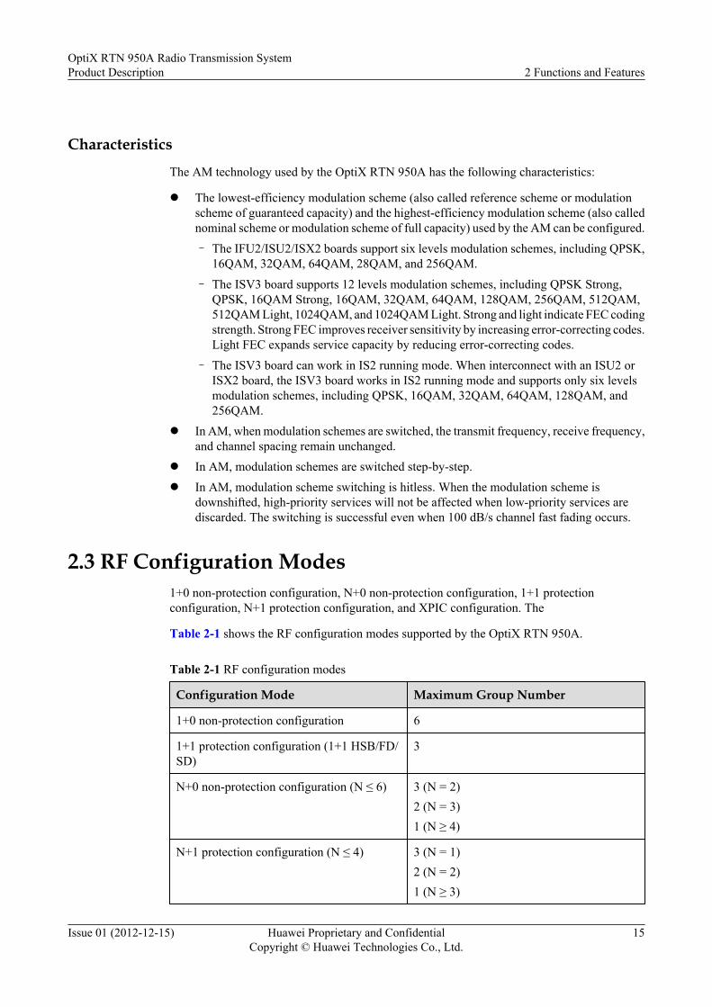
2.3 RF Configuration Modes1+0 non-protection configuration, N+0 non-protection configuration, 1+1 protectionconfiguration, N+1 protection configuration, and XPIC configuration. The
Table 2-1 shows the RF configuration modes supported by the OptiX RTN 950A.
Table 2-1 RF configuration modes
Configuration Mode Maximum Group Number
1+0 non-protection configuration 6
1+1 protection configuration (1+1 HSB/FD/SD)
3
N+0 non-protection configuration (N ≤ 6) 3 (N = 2)2 (N = 3)1 (N ≥ 4)
N+1 protection configuration (N ≤ 4) 3 (N = 1)2 (N = 2)1 (N ≥ 3)
OptiX RTN 950A Radio Transmission SystemProduct Description 2 Functions and Features
Issue 01 (2012-12-15) Huawei Proprietary and ConfidentialCopyright © Huawei Technologies Co., Ltd.
15

Configuration Mode Maximum Group Number
XPIC configuration 3
NOTEl 1+0 configuration in N directions is also called Nx(1+0) configuration.
l When two radio links in 1+0 non-protection configuration form a microwave ring network, the specificRF configuration (namely, east and west configuration) is formed. On a Hybrid microwave ringnetwork, SNCP can be configured for SDH/PDH services and ERPS can be configured for Ethernetservices. On a packet microwave ring network, MPLS APS or PW APS can be configured for packetservices.
l Two XPIC workgroups can form the XPIC 1+1 protection configuration.
2.4 CapacityThe OptiX RTN 950A is a high-capacity device.
2.4.1 Air Interface CapacityThe microwave air interface capacity depends on the IF board, ODU type, and microwaveworking mode.
Table 2-2 and Table 2-3 lists the microwave air interface capacities that the OptiX RTN950A supports.
Table 2-2 Air interface capacities (SDH radio)
Radio Link IF Board Maximum AirInterfaceCapacity
XPICConfiguration
Remarks
SDH ISU2 2xSTM-1 Not supported -
ISX2 2xSTM-1 Supported The XPIC function is providedusing two ISX2 boards.a
ISV3 2xSTM-1 Supported The XPIC function is providedusing two ISV3 boards.
NOTEa: When running in the IS2 mode, the ISV3 board can work with the ISX2 board to implement the XPIC function.
The XPIC function doubles the service capacity of the microwave channel at the same frequency bandwidth.
OptiX RTN 950A Radio Transmission SystemProduct Description 2 Functions and Features
Issue 01 (2012-12-15) Huawei Proprietary and ConfidentialCopyright © Huawei Technologies Co., Ltd.
16

Table 2-3 Air interface capacities (Integrated IP radio)
Radio Link IF Board MaximumNumber ofE1s
MaximumEthernetThroughput at AirInterfaces(Mbit/s)
XPICConfiguration
Remarks
Integrated IPradio
IFU2 75 360 to 420 Notsupported
-
ISU2 75 360 to 456 Notsupported
-
ISX2 75 360 to 456 Supported The XPIC function is providedusing two ISX2 boards.a
ISV3 75 480 to 609(none-XPIC)450 to 575(XPIC)
Supported The XPIC function is providedusing two ISV3 boards.
NOTEl a: When running in the IS2 mode, the ISV3 board can work with the ISX2 board to implement the XPIC function.
l ISU2, ISX2 and ISV3 boards support frame header compression at air interfaces, and their equivalent throughout of Ethernetservices at air interfaces can reach up to 1000 Mbit/s. For details, see Microwave Work Modes.
l The XPIC function doubles the service capacity of the microwave channel at the same frequency bandwidth.
2.4.2 Cross-Connect CapacityThe OptiX RTN 950A has a built-in MADM and provides full time division cross-connectionsfor VC-12/VC-3/VC-4 services equivalent to 32x32 VC-4s.
2.4.3 Switching CapacityThe OptiX RTN 950A has a built-in packet switching platform with the switching capacity of10 Gbit/s.
2.5 InterfacesThe OptiX RTN 950A provides a variety of interfaces.
2.5.1 Service InterfacesThe OptiX RTN 950A provides several service interfaces on the system control, switching, andtiming board, and it is also able to provide a wide-assortment of service interfaces by configuringappropriate service interface boards.
Table 2-4 lists the types and number of service interfaces that the system control, switching,and timing board supports for the OptiX RTN 950A.
OptiX RTN 950A Radio Transmission SystemProduct Description 2 Functions and Features
Issue 01 (2012-12-15) Huawei Proprietary and ConfidentialCopyright © Huawei Technologies Co., Ltd.
17

Table 2-4 Types and number of service interfaces that the system control, switching, and timingboard supports
System Control,Switching, andTiming Board
Service Interface Quantity
CSHO GE electrical interface (RJ45):10/100/1000BASE-T(X)
4
GE electrical interface (SFP) or GE/FEoptical interface (SFP):l GE electrical interface:
10/100/1000BASE-T(X)l GE optical interface: 1000BASE-SX/LX/
VX/ZX/BXl FE optical interface: 100BASE-FX/LX/
VX/ZX/BX
2
STM-1 electrical interface (SFP) orSTM-1 optical interface (SFP): Ie-1, S-1.1,L-1.1, and L-1.2
2
75-ohm or 120-ohm E1 interface 16
Table 2-5 Types and number of service interfaces that each service interface board supports
Service InterfaceBoard
Service Interface Quantity
EG4 GE electrical interface (RJ45) or GE/FEoptical interface (SFP):l GE electrical interface:
10/100/1000BASE-T(X)l GE optical interface: 1000BASE-SX/LX/
VX/ZX/BXl FE optical interface: 100BASE-FX/LX/
VX/ZX/BX
2
GE electrical interface (RJ45):10/100/1000BASE-T(X)
2
EG4P GE electrical interface (RJ45) or GE/FEoptical interface (SFP):l GE electrical interface:
10/100/1000BASE-T(X)l GE optical interface: 1000BASE-SX/LX/
VX/ZX/BXl FE optical interface: 100BASE-FX/LX/
VX/ZX/BX
2
OptiX RTN 950A Radio Transmission SystemProduct Description 2 Functions and Features
Issue 01 (2012-12-15) Huawei Proprietary and ConfidentialCopyright © Huawei Technologies Co., Ltd.
18

Service InterfaceBoard
Service Interface Quantity
GE electrical interface with power supply(RJ45): 10/100/1000BASE-T(X)
2
EFP8 FE electrical interface (RJ45): 10/100BASE-T(X)
8
EMS6 FE electrical interface (RJ45): 10/100BASE-T(X)
4
GE electrical interface (SFP) or GE opticalinterface (SFP):l GE electrical interface:
10/100/1000BASE-T(X)l GE optical interface: 1000BASE-SX/LX/
VX/ZX
2
SP3S 75-ohm or 120-ohm E1 interface 16
SP3D 75-ohm or 120-ohm E1 interface 32
CQ1 Channelized STM-1 electrical interface(SFP) orChannelized STM-1 optical interface (SFP):Ie-1, S-1.1, L-1.1, L-1.2, S-1.1-BX, L-1.1-BX
4
SL1DA STM-1 electrical interface (SFP) orSTM-1 optical interface (SFP): Ie-1, S-1.1,L-1.1, L-1.2
2
ML1 75-ohm or 120-ohm Smart E1 interface:supports CES E1, ATM/IMA E1, andFractional E1
16
MD1 75-ohm or 120-ohm Smart E1 interface:supports CES E1, ATM/IMA E1, andFractional E1
32
NOTE
l Smart E1 interfaces support multiple protocols through software configuration. Smart E1 interfaces on theOptiX RTN 950A support CES E1, ATM/IMA E1, ML-PPP and Fractional E1.
l Fractional E1 interfaces can make use of specific 64 kbit/s timeslots in framed E1 services. If the E1 interfaceis applied to Fractional CES, certain timeslots in E1 services are emulated. If the E1 interface is applied toFractional IMA, certain timeslots in E1 services serve as the member links of IMA groups.
l Channelized STM-1 interfaces (c-STM-1) support the channelization of STM-1 into 63 E1 channels. TheE1 channels support CES and ML-PPP.
2.5.2 Management and Auxiliary Interfaces
OptiX RTN 950A Radio Transmission SystemProduct Description 2 Functions and Features
Issue 01 (2012-12-15) Huawei Proprietary and ConfidentialCopyright © Huawei Technologies Co., Ltd.
19

Management and Auxiliary Interfaces
Table 2-6 Types and number of management and auxiliary interfaces
Interface Description Quantity
External clockinterface
120-ohm 2,048 kbit/s or 2,048 kHz clock input andoutput interfacea
1
External timeinterface
External time input or output interface (RS-422level, 1PPS+TOD or DCLS format)a, b
2
Managementinterface
10/100BASE-T(X) NM interface 1
NM serial interface 1
10/100BASE-T(X) NM cascading interface 1
Auxiliary interface Orderwire interface 1
RS-232 asynchronous data interface 1
64 kbit/s synchronous data interfacec 1
Wayside E1 interface 1
Alarm interface Alarm input interface 4
Alarm output interface 2
Outdoor cabinetmonitoringinterface
RS-485 outdoor cabinet monitoring interfaceb 1
NOTE
l a: The external clock interface, external time interface, and wayside E1 interface are combined into onephysical interface. This interface can also transparently transmit the DCC bytes, orderwire overhead bytes,and synchronous/asynchronous data overhead bytes. However, this interface can implement only onefunction at a time.
l b: External time interface 2 and the outdoor cabinet monitoring interface are combined into one physicalinterface. This interface can implement only one function at a time.
l c:The 64 kbit/s synchronous data interface can transparently transmit the orderwire byte. However, oneinterface can implement only one of the following two functions: 64 kbit/s synchronous data interface andtransparent transmission of the orderwire byte.
l The CSHO board provides the external clock interface and the management interface. The AUX boardprovides the auxiliary interface and the alarm interface.
Auxiliary Service ChannelAuxiliary services and NM messages are transmitted by overhead bytes over a radio link. Fordetails, see Table 2-7.
OptiX RTN 950A Radio Transmission SystemProduct Description 2 Functions and Features
Issue 01 (2012-12-15) Huawei Proprietary and ConfidentialCopyright © Huawei Technologies Co., Ltd.
20

Table 2-7 Auxiliary services channels provided by each microwave interface
Service/Message Type Microwave Frame Overhead
Quantity of Paths Path Rate
Asynchronous data service 1 ≤ 19.2 kbit/s
Synchronous data service 1 64 kbit/s
Orderwire phone service 1 64 kbit/s
Wayside E1 service 1 2048 kbit/s (in the SDH radio link)
DCC path 1 l 64 kbit/s (in the PDH radio linkwhich the capacity is lower than16xE1)
l 192 kbit/s (in the PDH radio linkwhich the capacity is not lower than16xE1)
l 192 kbit/s, 576kbit/s, or 768kbit/s(in the SDH radio link)
l 192 kbit/s (in Integrated IP radiolink)
2.6 Cross-Polarization Interference CancellationCross-polarization interference cancellation (XPIC) technology is used together with co-channeldual-polarization (CCDP). The application of the two technologies doubles the wireless linkcapacity over the same channel.
CCDP transmission adopts a horizontally polarized wave and a vertically polarized wave on onechannel to transmit two channels of signals. Ideally, for CCDP transmissions, there will not beany interference between the two orthogonal signals although they are on the same frequency.In actual practice, despite the orthogonality of the two signals, interference between the signalsinevitably occurs due to cross-polarization discrimination (XPD) of the antenna and channeldegradation. To cancel the interference, XPIC technology is used to receive signals horizontallyand vertically. The signals in the two directions are then processed and the original signals arerecovered from interfered signals.
OptiX RTN 950A Radio Transmission SystemProduct Description 2 Functions and Features
Issue 01 (2012-12-15) Huawei Proprietary and ConfidentialCopyright © Huawei Technologies Co., Ltd.
21

Figure 2-5 CCDP channel configuration , used when XPIC is used
HV
ModemODU 1
ODU 2
f1
f1
ODU 1
ODU 2
f1
f1
Site A Site B
f1
Modem
Modem
Modem
Service
Service
Service
Service
V: vertical polarization direction
H: horizontal polarization direction
Service singnal
2.7 Automatic Transmit Power ControlAutomatic transmit power control (ATPC) enables the output power of the transmitter toautomatically trace the level fluctuation at the receive end within the ATPC control range. Thisfeature reduces the interference with neighboring systems and residual BER.
Figure 2-6 Relationship between the RSL and TSL
T
Up-fading
Down-fading
2 dB
TSL/RSL
TSL
RSL2 dBCentral value of the
ATPC upperthreshold and the
ATPC lower threshold
2.8 MPLS/PWE3 FunctionThe OptiX RTN 950A uses an MPLS that is optimized for the telecom bearer network as thepacket forwarding mechanism for packet transmission of carrier-class services. The OptiX RTN950A uses PWE3 technology as the service bearer technology to implement MPLS networkaccess for various types of services.
OptiX RTN 950A Radio Transmission SystemProduct Description 2 Functions and Features
Issue 01 (2012-12-15) Huawei Proprietary and ConfidentialCopyright © Huawei Technologies Co., Ltd.
22

Table 2-8 MPLS/PWE3 functions
Function and Feature Description
MPLStunnel
Setup mode Static LSPs
Bearer mode l Ethernet portl IP microwave portl MLPPP link
Protection 1:1 MPLS tunnel APS
OAM l MPLS OAM that complies with ITU-T Y.1710 and ITU-T Y.1711
l MPLS-TP LSP OAM that complies withITU-T Y.1731
l LSP ping and LSP traceroute functions
PWE3 TDM PWE3 Emulationmode
l SAToPl CESoPSN
Packet loadingtime
125 μs to 5000 μs
Jittercompensationbuffering time
375 μs to 16000 μs
ATM PWE3 Mapping mode l 1-to-1 ATM VCC mappingl N-to-1 ATM VCC mappingl 1-to-1 ATM VPC mappingl N-to-1 ATM VPC mapping
Maximumnumber ofconcatenatedcells
31
Cellconcatenationwait time
100 μs to 50000 μs
TransparentlytransmittedATM service
Supported
ETH PWE3 Encapsulationmode
l Raw model Tagged mode
Service type l E-Linel E-Aggrl E-LAN (VPLS)
OptiX RTN 950A Radio Transmission SystemProduct Description 2 Functions and Features
Issue 01 (2012-12-15) Huawei Proprietary and ConfidentialCopyright © Huawei Technologies Co., Ltd.
23

Function and Feature Description
Setup mode Static PWs
Control Word supported
Numbers of PWs Supports a maximum of 1024 PWs.
Protection 1:1 PW APS
OAM l PW OAM that complies with ITU-T Y.1710 and ITU-T Y.1711
l MPLS-TP PW OAM that complies withITU-T Y.1731
l VCCVl PW ping and PW traceroute functionsl ITU-T Y.1731-compliant packet loss
measurement, delay measurement, anddelay variation measurement
l Intelligent service fault diagnosis
MS-PW Supported
Configurable bandwidth Supported
2.9 Ethernet Service Processing CapabilityThe OptiX RTN 950A has powerful Ethernet service processing capability.
Table 2-9 Ethernet service processing capability
Item Description
Ethernet servicetype
l Native Ethernet services: E-Line service and E-LAN servicel PW-carried Ethernet services: E-Line service, E-Aggr service, and
E-LAN (VPLS) service
Range ofmaximum framelength
1518 bytes to 9600 bytes
VLAN l Adds, deletes, and switches VLAN tags that comply with IEEE802.1q/p, and forwards packets based on VLAN tags.
l Processes packets based on the port tag attribute (Tag/Hybrid/Access).
l The VLAN ID ranges from 1 to 4094.
OptiX RTN 950A Radio Transmission SystemProduct Description 2 Functions and Features
Issue 01 (2012-12-15) Huawei Proprietary and ConfidentialCopyright © Huawei Technologies Co., Ltd.
24

Item Description
MAC address l The E-LAN service supports the MAC address self learningcapability in two learning modes: SVL and IVL.
l MAC addresses can be filtered; that is, MAC addresses can beblacklisted.
l Static MAC address entries can be set.l The capacity of the MAC address table is 16 k (including static
entities and blacklist entities).l The MAC address aging time can be configured.
Spanning tree Supports the MSTP protocol, and generates only the Common andInternal Spanning Tree (CIST). The functions of the MSTP protocol areequal to those of the RSTP protocol.
Link aggregation(LAG)
Applies to the FE/GE port and microwave port.l Supports manual aggregation and static aggregationl Supports load sharing and non-load sharing.l The load sharing hash algorithm is implemented based on MAC
addresses, IP addresses, or MPLS labels, and supports the specifiedmode and automatic mode.
Physical linkaggregation(PLA)
The physical layer aggregation (PLA) function and enhanced physicallayer aggregation (EPLA) are supported at air interfacesPLA and EPLA are Layer 1 link aggregation group (L1 LAG)technology, which shares load based on the bandwidth at the physicallayer to achieve link aggregation.A PLA group supports a maximum of two member links. An EPLAgroup supports a maximum of four member links.
ERPS Supports ITU-T G.8032v1-compliant ring network protection forEthernet services.
LPT Disables the remote Ethernet port that is connected to the user equipmentwhen the transmission network or local port fails.
QoS Supports QoS. For details, see 2.10 QoS.
Traffic controlfunction
Supports the IEEE 802.3x-compliant traffic control function.
ETH-OAM l Supports IEEE 802.1ag- and IEEE 802.3ah-compliant ETH-OAMfunctions.
l Supports ITU-T Y.1731-compliant ETH-OAM functions, supportspacket loss measurement, delay measurement, and delay variationmeasurement.
OptiX RTN 950A Radio Transmission SystemProduct Description 2 Functions and Features
Issue 01 (2012-12-15) Huawei Proprietary and ConfidentialCopyright © Huawei Technologies Co., Ltd.
25

Item Description
Ethernetperformancemonitoring
l Supports IETF RFC2819-compliant RMON performancemonitoring.
l Measures real-time and historical traffic and bandwidth utilizationfor ports.
l Measures real-time and historical performance events for DSdomains, flows, VLANs, traffics on UNI side, PWs, and egressqueues.
l Measures packet loss due to congestion for flows.l Measures packet loss due to congestion for PWs and egress queues.
SynchronousEthernet
Supports ITU-T G.8261- and ITU-T G.8262-compliant synchronousEthernet.
EoPDH Supported. The EFP8 board provides the EoPDH function.
EoSDH Supported. The EMS6 board provides the EoSDH function.
NOTE
l The E-Line service is an Ethernet private line service. The OptiX RTN 950A supports a maximum of 1024E-Line services.
l For Native Ethernet services, the OptiX RTN 950A supports E-Line services based on the port, port+VLAN, and port+QinQ.
l For PW-carried Ethernet services, the OptiX RTN 950A supports E-Line services based on the port,port+VLAN, and port+QinQ.
l The E-Aggr service is an Ethernet aggregation service. The OptiX RTN 950A supports E-Aggr servicesfrom multiple UNIs to one PW and E-Aggr services from multiple PWs to one UNI. The OptiX RTN950A supports a maximum of 128 E-Aggr services.
l The E-LAN service is an Ethernet local area network (LAN) service.
l For Native Ethernet services, the OptiX RTN 950A supports the E-LAN service based on the 802.1dbridge, 802.1q bridge, and 802.1ad bridge. The bridge supports a maximum of 1024 logical ports.
l For PW-carried Ethernet services, the OptiX RTN 950A supports virtual private LAN services (VPLS)based on virtual switch instances (VSI). The OptiX RTN 950A supports a maximum of 32 VSIs and512 logical ports.
2.10 QoSThe OptiX RTN 950A provides improved quality of service (QoS) and supports the followingeight types of per-hop behaviors (PHBs): BE, AF1, AF2, AF3, AF4, EF, CS6, and CS7.Therefore, network carriers can offer various QoS levels of service guarantees and buildnetworks that carry data, voice, and video services.
OptiX RTN 950A Radio Transmission SystemProduct Description 2 Functions and Features
Issue 01 (2012-12-15) Huawei Proprietary and ConfidentialCopyright © Huawei Technologies Co., Ltd.
26

Table 2-10 QoS features
Feature Performance
DiffServ l For Ethernet services, supports mapping the Ethernet service intodifferent PHB service levels based on the C-VLAN priority, S-VLANpriority, IP DSCP value, and MPLS EXP value.
l For ATM services, supports flexible mapping between the ATMservice categories (CBR, UBR, UBR+, rtVBR, and nrtVBR) andPHB service levels.
l For CES services, the PHB service level of each CES service can beset manually (EF by default).
Trafficclassification
Supports port traffic classification based on VLAN ID, VLAN priority,or DSCP.
Traffic policing Supports flow-based traffic policing and the setting of PIR and CIR insteps of 64 kbit/s.
Queue scheduling l Each Ethernet port or Integrated IP radio port supports eight levelsof priority scheduling.
l Flexibly sets the queue scheduling scheme for each Ethernet port andIntegrated IP radio port. The queue scheduling modes include SP, SP+WRR, and WRR.
Congestionavoidance
Drops packets in tail drop mode.
Traffic shaping l Supports the shaping for the specified port, priority queue, or serviceflow.
l Supports a step of 64 kbit/s for the PIR and CIR.
Figure 2-7 Typical QoS application (Native Ethernet services)
Fowarding
Queues SchedulingClassifing
Ingress Egress
PacketSwitching
CS7CS6
EFAF4AF3AF2AF1BE
Policing
CAR
Flow
Mapping
DiffServShaping
Shaping
2.11 Clock FeaturesThe OptiX RTN 950A supports physical-layer clock synchronization, time synchronization overpacket networks, and IEEE 1588v2 time synchronization, meeting the clock and time
OptiX RTN 950A Radio Transmission SystemProduct Description 2 Functions and Features
Issue 01 (2012-12-15) Huawei Proprietary and ConfidentialCopyright © Huawei Technologies Co., Ltd.
27

synchronization requirements of mobile networks. In addition, the OptiX RTN 950A providesan advanced clock protection mechanism.
Clock synchronization
Table 2-11 Clock synchronization features
Item Description
Equipment clock Supports the three modes as defined in ITU-T G.813: tracingmode, holdover mode, and free-run mode.
Clock synchronization Supports the following clock sources:l SDH line clockl E1 tributary clockl Radio link clockl Synchronous Ethernet clockl Channelized STM-1 line clockl E1 clock of the E1 channel mapped in Channelized STM-1l 2048 kbit/s or 2048 kHz external clockl IEEE 1588v2 clockl IEEE 1588 ACR clock
SSM protocol/ExtendedSSM protocol
Supported. SSM information can be transmitted in thefollowing interfaces:l SDH linel SDH radio linkl Integrated IP radio linkl Synchronization Ethernet interfacel 2048 kbit/s external clock interface, supporting the SSM
protocol and not supporting the extended SSM protocol
Tributary clock l Supports retiming for Native E1 and CES E1 services.l Supports the transparent transmission of E1 clocks.l Supports CES ACR clocks.
Channelized STM-1 lineclock re-timing
Supported. CQ1 boards can use the receive clock of STM-1signals as transmit clock.
Output of the external clock Supported (120-ohm interface complying with G.703, 2048kbit/s or 2048 kHz mode)
OptiX RTN 950A Radio Transmission SystemProduct Description 2 Functions and Features
Issue 01 (2012-12-15) Huawei Proprietary and ConfidentialCopyright © Huawei Technologies Co., Ltd.
28

Time synchronization
Table 2-12 Time synchronization features
Item Description
Clock Model OC, BC, TC, TC+BC
Input of the externaltime
Supported
Time sourceselection andprotection
l BMC algorithml Static selection for time sources
Timesynchronization
Supports the following time sources:l IEEE 1588v2 clockl External time interface
Time transparenttransmission
Transparent transmission of IEEE 1588v2 time signals
Output of theexternal time
Supported
2.12 Protection CapabilityThe OptiX RTN 950A provides a variety of protection schemes.
Table 2-13 Protection schemes
Item Description
Equipment-levelprotection
Power input 1+1 hot backup
Radio links 1+1 HSB/SD/FD protection
N+1 protection
Network-levelprotection
MPLS MPLS tunnel 1:1 protection
PW PW 1:1 protection
Ethernet LAG protection
ERPS protection
MSTP protection
PLA protection and EPLA protection (only forradio links)
ATM over E1 IMA protection
OptiX RTN 950A Radio Transmission SystemProduct Description 2 Functions and Features
Issue 01 (2012-12-15) Huawei Proprietary and ConfidentialCopyright © Huawei Technologies Co., Ltd.
29

Item Description
Tunnel over E1 ML-PPP protection
TDM services SNCP
STM-1 1+1 or 1:N linear multiplex section protection
Channelized STM-1 1:1 linear multiplex section protection
2.13 Network ManagementThe OptiX RTN 950A supports multiple network management (NM) modes and providescomprehensive NM information exchange schemes.
NM Mode
The OptiX RTN 950A supports the following functions:
l Uses the iManager Web LCT to manage one local NE or one remote NE on a per-NE basis.l Uses the iManager U2000 to centralizedly manage OptiX RTN NEs and other OptiX NEs
at the network level.l Uses the Simple Network Management Protocol (SNMP) agent to query alarms,
performance events, and some configuration information.
LLDP Function
The OptiX RTN 950A and another device (such as a base station) that are both enabled with theLink Layer Discovery Protocol (LLDP) can discover each other. The LLDP function helps toarchive:l Display of the topology of a network that comprises different types of equipment on an
NMS.l Simplified fault diagnosis.
NM Information Exchange Schemes
The OptiX RTN 950A supports inband DCN and outband DCN.
Table 2-14 DCN information exchange schemes
Item Specifications
DCNchannel
DCC bytes PDHmicrowave
One or three DCC bytes that are defined byHuawei
Integrated IPradio
Three DCC bytes that are defined by Huawei
SDHmicrowave
D1-D3, D4-D12, or D1-D12 bytes
OptiX RTN 950A Radio Transmission SystemProduct Description 2 Functions and Features
Issue 01 (2012-12-15) Huawei Proprietary and ConfidentialCopyright © Huawei Technologies Co., Ltd.
30

Item Specifications
SDH line D1-D3, D4-D12, or D1-D12 bytes
ChannelizedSTM-1 line
D1-D3, D4-D12, or D1-D12 bytes
Externalclockinterface
Supports the transparent transmission ofDCC bytes through the external clockinterface.
Network managementinterface
Supports one network management Ethernetinterface or one network managementEthernet cascade interface.
Inband DCN Radio link The inband DCN channel is marked with theVLAN tag and its bandwidth is configurable.
FE/GEinterface
The inband DCN channel is marked with theVLAN tag and its bandwidth is configurable.
Smart E1interface
The inband DCN signals are carried by ML-PPP links. The inband DCN channel ismarked with the VLAN tag and its bandwidthis configurable.
ChannelizedSTM-1interface
The inband DCN signals are carried by ML-PPP links. The inband DCN channel ismarked with the VLAN tag and its bandwidthis configurable.
Networkmanagementprotocol
HWECC protocol Supported
IP protocols Supported
L2 DCN Supported
2.14 Easy InstallationThe OptiX RTN 950A supports several installation modes. That is, the installation is flexibleand convenient.
The IDU can be installed on the following types of cabinets and surfaces:
l In a 300 mm or 600 mm ETSI cabinetl In a 450 mm or 600 mm 19-inch cabinetl In an open cabinetl In an outdoor cabinet
The ODU supports two installation modes: direct mounting and separate mounting.
OptiX RTN 950A Radio Transmission SystemProduct Description 2 Functions and Features
Issue 01 (2012-12-15) Huawei Proprietary and ConfidentialCopyright © Huawei Technologies Co., Ltd.
31

2.15 Easy MaintenanceThe OptiX RTN 950A provides plentiful maintenance features.
2.15.1 Equipment-level OAMThe OptiX RTN 950A provides several maintenance features that effectively reduce the costsassociated with maintaining the equipment.
Table 2-15 describes the OAM functions supported by the OptiX RTN 950A.
Table 2-15 Equipment-level OAM
Function Description
Management andmonitoring
l The OptiX RTN 950A can be managed together with opticaltransmission equipment by the U2000.
l Supports various alarms and performance events.l Supports RMON performance statistics on various types of
objects.l Supports the monitoring and graphic display of key radio
transmission performance indicators such as microwave transmitpower, received power, signal to noise ratio (SNR), and air-interface BER.
l Supports the monitoring and graphic display of Ethernetperformance specifications such as port traffic and bandwidthutilization.
Hardwaremaintenance
l Each IDU board has running and alarm status indicators.l All the indicators and cable interfaces are available on the front
panel of the IDU.l The system control, switching, and timing board, IF board, service
board, and fan board support hot swapping.
Diagnosis andTesting
l Supports PRBS tests by IF ports.l Supports PRBS tests by Native E1 and CES E1 ports.l Simulates Ethernet meters to test packet loss, delay, and
throughput.l Supports various loopback types over service ports and IF ports.
OptiX RTN 950A Radio Transmission SystemProduct Description 2 Functions and Features
Issue 01 (2012-12-15) Huawei Proprietary and ConfidentialCopyright © Huawei Technologies Co., Ltd.
32

Function Description
Packet service OAM l Supports IEEE 802.1ag- and IEEE 802.3ah-compliant ETH OAMfunctions.
l Supports ITU-T Y.1731-compliant packet loss measurement,delay measurement, and delay variation measurement for Ethernetservices.
l Supports the ITUT-T Y.1711-compliant MPLS OAM functionand LSP ping/traceroute.
l Supports the ITUT-T Y.1711-compliant PW OAM function andPW ping/traceroute.
l Supports the ITU-T Y.1731-compliant MPLS-TP LSP OAM andPW OAM functions.
Databasemanagement
l Remotely backs up and restores the NE database by using theU2000.
l The CF card that stores the configuration data and software canbe replaced online. Therefore, users can load the data or upgradethe software by replacing the CF card.
l Two copies of software and data are stored in the flash memoryof the system control, switching, and timing board to meet thesmooth upgrade requirements.
Softwaremanagement
l Remotely loads NE software and data by using the U2000 andprovides a quick NE upgrade solution.
l Supports the NSF function. SDH/PDH services and Ethernet E-Line services are not interrupted during warm resets on NEsoftware.
l Supports hot patch loading. Users can upgrade software withoutinterrupting services.
l Supports software version rollback so that original system servicesare restored despite software upgrade failures.
2.15.2 Packet Services OAM (TP-Assist)The OptiX RTN 950A works with the iManager U2000 to allow hierarchy OAM of packetservices. Packet OAM supports end-to-end service configuration, acceptance tests, and faultlocating, therefore simplifying operation and maintenance of packet services.
Table 2-16 describes the packet OAM functions supported by the OptiX RTN 950A.
OptiX RTN 950A Radio Transmission SystemProduct Description 2 Functions and Features
Issue 01 (2012-12-15) Huawei Proprietary and ConfidentialCopyright © Huawei Technologies Co., Ltd.
33

Table 2-16 Packet OAM (TP-Assist)
OAM Stage Subitem Description
End-to-endserviceconfiguration
End-to-end packetserviceconfiguration
l Supports end-to-end configuration of Native E-Line/E-LAN services.
l Supports end-to-end configuration of MPLStunnel and ETH PWE3.
Automaticdeployment ofalarmmanagement
l Automatically configures end-to-end ETHOAM during Native Ethernet serviceconfiguration and supports connectivity testsand alarm reporting.
l Automatically configures end-to-end MPLS-TP OAM during MPLS tunnel serviceconfiguration and supports connectivity testsand alarm reporting.
l Automatically configures end-to-end ETH-OAM during ETH PWE3 service configurationand supports connectivity tests and alarmreporting.
Acceptance tests Serviceconnectivity tests
l Supports one-click connectivity test of NativeE-Line and E-LAN services.
l Supports one-click connectivity test of the E-Line services carried by MPLS tunnels.
Serviceperformance tests
l Supports one-click test on packet loss, delay,and delay jitter of Native E-Line and E-LANservices.
l Supports one-click test on packet loss, delay,and delay jitter of the E-Line services carriedby MPLS tunnels.
l Simulates Ethernet meters to test packet loss,delay, and throughput.
Fault locating Port IP ping l Supports local ping at UNI ports.l Supports remote ping at UNI ports.
Port monitoring l Reports alarms indicating Ethernet signal loss.l Reports alarms indicating Ethernet port auto-
negotiation failures (half-duplex alarm).
Service loopbackdetecting
l Detects loopbacks in E-Line services.l Automatically disables the service ports
involved in a loop.
Intelligent faultdiagnosis
l Checks the integrity of hardware, software, andconfiguration along a service path.
l Detects zero traffic and packet loss along aservice path.
OptiX RTN 950A Radio Transmission SystemProduct Description 2 Functions and Features
Issue 01 (2012-12-15) Huawei Proprietary and ConfidentialCopyright © Huawei Technologies Co., Ltd.
34

OAM Stage Subitem Description
Performancestatistics
l Measures real-time and historical performanceevents for Ports, DS domains, flows, VLANs,UNI-side services, PWs, tunnel, and egressqueues.
l Measures packet loss due to congestion forflows, PWs bandwidth, and egress queues.
Performancemonitoring
l Reports packet loss threshold-crossing alarmsby DS domain, traffic classification, VLAN, V-UNI, PW, and egress queue.
l Reports port bandwidth utilization threshold-crossing alarms.
l Reports packet loss threshold-crossing alarmsfor flows, PWs bandwidth, and egress queues.
l Reports zero-traffic alarms for Ports, DSdomains, flows, VLANs, UNI-side services,PWs, and egress queues.
2.16 Security ManagementThe OptiX RTN 950A can prevent unauthorized logins and operations, ensuring equipmentmanagement security.
Overview of Hardware Security
The OptiX RTN 950A adopts high-reliability hardware design to ensure that the system runsproperly under security threats.
The following hardware preventive measures are provided:l Microwave interfaces: The FEC encoding mode is adopted and the adaptive time-domain
equalizer for baseband signals is used. This enables the microwave interfaces to toleratestrong interference. Therefore, an interceptor cannot restore the contents in a data frame ifcoding details and service configurations are not obtained.
l Modular design: Control units are separated from service units and service units areseparated from each other. In this manner, a fault on any unit can be properly isolated,minimizing the impact of the fault on other units in the system.
l CPU flow control: Data flow sent to the CPU for processing is classified and controlled toprevent the CPU from being attacked by a large number of packets. This ensures that theCPU operates properly under attacks.
Overview of Software Security
The OptiX RTN 950A processes two categories of data: O&M data and service data. Thepreceding data is transmitted over independent paths and does not affect each other. Therefore,services on the OptiX RTN 950 are processed on two planes:l Management plane
OptiX RTN 950A Radio Transmission SystemProduct Description 2 Functions and Features
Issue 01 (2012-12-15) Huawei Proprietary and ConfidentialCopyright © Huawei Technologies Co., Ltd.
35

The management plane provides access to the required equipment and managementfunctions, such as managing accounts and passwords, communication protocols, and alarmreporting. The security feature of the management plane enables secure device access,concentrated management, and thorough security audit.
l Data plane
The data plane processes service data that enters the devices and forwards service datapackets according to hardware forwarding entries. On one hand, the data plane preventsuser service packets from being intercepted, modified, or deleted, which endangers theconfidentiality and completeness of user data. On the other hand, the data plane ensuresthe control of hardware forwarding actions, preventing forwarding entries from beingattacked or modified. In this manner, the forwarding plane of the devices can function stablyand reliably.
Table 2-17lists the security functions provided by the OptiX RTN 950A.
Table 2-17 Security functions of the three planes
Plane Function Description
Management plane
Account andpasswordmanagement
Manages and saves device maintenance accounts.
Localauthentication andauthorization
Checks account validity and performs authorization.
RADIUSauthorization andauthentication
Checks account validity and remotely performsauthorization in the concentrated mode, reducing themaintenance cost.
Security log Records actions about account management.
Operation log Records non-query operations.
SYSLOGManagement
Functions as a standard solution for saving logs offline,effectively resolving the deficient saving spaceproblem.
TCP/IP protocolstack attackprevention
Provides basic TCP/IP attack prevention capability,such as attacks from incorrect IP packets, ICMP ping/jolt, and DoS.
Access Control List(ACL)
Provides ACL based on IP addresses and port numbers.
SSL/TLSencryptioncommunication
Supports SSL3.0/TLS1.0 and provides secureencrypted tunnels based on security certifications.
SSH securitycommunication
Provides the SSHv2 server and SFTP client service.
OSPF routeprotocol
Provides OSPFv2, capable of standard MD5authentication.
OptiX RTN 950A Radio Transmission SystemProduct Description 2 Functions and Features
Issue 01 (2012-12-15) Huawei Proprietary and ConfidentialCopyright © Huawei Technologies Co., Ltd.
36

Plane Function Description
NTP protocol Provides NTPv3, capable of MD5 authentication andauthorization control.
SNMP managementprotocol
Provides SNMPv3, capable of security authenticationand data encryption functions.
Data plane Flow control Monitors port traffic. Suppresses multicast packets,discards unknown unicast/multicast packets, and usesQoS to control service traffic.
Discarding of errorpackets
Discards invalid error packets. For example, a packetwhose size is smaller than 46 bytes.
Loop avoidance Detects loopback at services ports, blocks loopback,and supports service loopback detection of Ethernetports.
Layer 2 serviceaccess control
Provides the access control capabilities: filtering ofstatic MAC addresses, blacklist, learning andforbidding of MAC addresses, and filtering based oncomplex traffic classification.
Service isolation Provides three isolation methods: Layer 2 logicalisolation, horizontal isolation, and physical isolation.
Strict isolation ofuser services
Strictly isolates MPLS services within the carriernetworks and from client-side services.
2.17 Energy SavingThe OptiX RTN 950A uses various types of technologies to reduce the amount of energy thatthe device consumes. The device:
l Uses a streamlined scheme for board design.
l Replaces ordinary chips with ASIC chips that consume less power.
l Uses high-efficiency power modules.
l Supports intelligent adjustment of the fan speed that dissipates heat in a timely manner,reduces power consumption, and minimizes noise.
l Shuts down idle FE/GE ports and SFP optical modules.
2.18 Environmental ProtectionThe OptiX RTN 950A is designed to meet or exceed environmental protection requirements.The product complies with the RoHS directive and WEEE directive.
l The OptiX RTN 950A undergoes a compulsory packing process that limits the size of thepackage containing the equipment and accessories to three times that of the equipmentdimensions.
OptiX RTN 950A Radio Transmission SystemProduct Description 2 Functions and Features
Issue 01 (2012-12-15) Huawei Proprietary and ConfidentialCopyright © Huawei Technologies Co., Ltd.
37

l The product is designed for easy unpacking. In addition, all hazardous substances containedin the packaging decompose quickly.
l Every plastic component that weighs over 25 g is labeled according to the standards of ISO11469 and ISO 1043-1 to ISO 1043-4. All components and packages of the equipment areprovided with standard labels for recycling.
l Plugs and connectors are easy to find and the associated operations can be performed usingstandard tools.
l All the accompanying materials (such as labels) are easy to remove. Certain types ofidentifying information (such as silkscreens) are printed on the front panel or chassis.
OptiX RTN 950A Radio Transmission SystemProduct Description 2 Functions and Features
Issue 01 (2012-12-15) Huawei Proprietary and ConfidentialCopyright © Huawei Technologies Co., Ltd.
38

3 Product Structure
About This Chapter
This chapter describes the system architecture, hardware architecture, and software architectureof the product, in addition to how the system processes service signals.
3.1 System ArchitectureThe OptiX RTN 950A consists of a series of functional units, including the service interfaceunit, timeslot cross-connect unit, packet switching unit, IF unit, control unit, clock unit, auxiliaryinterface unit, fan unit, power unit, and ODU.
3.2 Hardware StructureThe OptiX RTN 950A adopts a split structure. The system consists of the IDU 950A and theODU. An ODU is connected to the IDU 950A through an IF cable. The IF cable transmits IFservice signals and the O&M signals of the ODU and also supplies -48 V DC power to the ODU.
3.3 Software StructureThe OptiX RTN 950A software consists of the NMS software, IDU software, and ODU software.
3.4 Service Signal Processing FlowThe signal processing flows for the SDH microwave, Hybrid microwave, and packet microwaveare different.
OptiX RTN 950A Radio Transmission SystemProduct Description 3 Product Structure
Issue 01 (2012-12-15) Huawei Proprietary and ConfidentialCopyright © Huawei Technologies Co., Ltd.
39

3.1 System ArchitectureThe OptiX RTN 950A consists of a series of functional units, including the service interfaceunit, timeslot cross-connect unit, packet switching unit, IF unit, control unit, clock unit, auxiliaryinterface unit, fan unit, power unit, and ODU.
Figure 3-1 Block diagram
Sync/Async dataExternal alarm
Packetswitching
unit
IF unit
ODU
E1(TDM/ATM)
-48V DC
IDU
FE/GE
Ethernetsignal
Timeslotcross-
connectunit
VC-4signal
Orderwire
Serviceinterface
unit
Control andoverhead bus
Fanunit
Clockunit
Controlunit
Auxiliaryinterface
unit
Powerunit
External clock NM interface
Ethernetsignal
VC-4signal
IF signal
RFsignal
Antenna
STM-1
External time
Table 3-1 Functional units
Functional Unit Function
Service interfaceunit
l Accesses TDM E1 signals.l Accesses ATM/IMA E1 signals, and demultiplexes ATM services
from ATM/IMA E1 signals.l Accesses STM-1 signals.l Accesses FE/GE signals.l Uses the EoSDH/EoPDH function to encapsulate Ethernet services
into SDH or E1 signals.l Performs E1/ATM/Ethernet service emulation based on PWE3.
Timeslot cross-connect unit
Provides the cross-connect function and grooms TDM services.
OptiX RTN 950A Radio Transmission SystemProduct Description 3 Product Structure
Issue 01 (2012-12-15) Huawei Proprietary and ConfidentialCopyright © Huawei Technologies Co., Ltd.
40

Functional Unit Function
Packet switchingunit
l Processes Ethernet services and forwards packets.l Processes MPLS labels and forwards packets.l Processes PW labels and forwards packets.
IF unit l Maps service signals to microwave frame signals and demapsmicrowave frame signals to service signals.
l Performs conversion between microwave frame signals and IFanalog signals.
l Provides the O&M channel between the IDU and the ODU.l Supports FEC.
Control unit l Provides the system communications and control.l Provides the system configuration and management.l Collects alarms and monitors performance.l Processes overheads.
Clock unit l Traces the clock source signal and provides various clock signalsfor the system.
l Supports input and output of external clock.l Supports input or output of external time signal.l Provides the time synchronization function.
Auxiliary interfaceunit
l Provides the asynchronous data interface.l Provides the external alarm input/output interface.
Power unit l Accesses -48 V V DC power.l Provides DC power for the IDU.l Provides -48 V DC power for the ODU.
Fan unit Provides air cooling for the IDU.
3.2 Hardware StructureThe OptiX RTN 950A adopts a split structure. The system consists of the IDU 950A and theODU. An ODU is connected to the IDU 950A through an IF cable. The IF cable transmits IFservice signals and the O&M signals of the ODU and also supplies -48 V DC power to the ODU.
3.2.1 IDUThe IDU 950A is the indoor unit of the OptiX RTN 950A.
The IDU 950A uses a card plug-in design. It implements different functions by configuringdifferent types of boards. All service boards support hot swapping.
OptiX RTN 950A Radio Transmission SystemProduct Description 3 Product Structure
Issue 01 (2012-12-15) Huawei Proprietary and ConfidentialCopyright © Huawei Technologies Co., Ltd.
41

Figure 3-2 IDU slot layout
Slot 7 (CSHO)
Slot 1 (EXT)
Slot 5 (EXT)
Slot 3 (EXT)
Slot 2 (EXT)
Slot 4 (EXT)
Slot 6 (EXT)Slot 11(FAN)
NOTE
"EXT" represents an extended slot, which can house any type of IF board or interface board.
Table 3-2 List of the IDU boards
BoardAcronym
Board Name Valid SlotDescription
CSHO Hybrid systemcontrol,switching, andtiming board
Slot 7 l Provides full time division cross-connections forVC-12/VC-3/VC-4 services equivalent to 32x32VC-4s.
l Provides the 10 Gbit/s packet switching capability.l Performs system communication and control.l Provides two-48 V/-60 V DC power input.l Provides the clock processing function, supports one
external clock input/output and two external timeinputs/outputs. External time interface 1 shares aport with the external clock interface.
l Uses SFP modules to provide two STM-1 optical/electrical interfaces.
l Provides sixteen TDM E1 interfaces. Supports 75-ohm/120-ohm adaptive impedance.
l Provides six GE interfaces, of which four can be onlyRJ45 GE electrical interfaces, and the other two canbe GE/FE optical interfaces or GE electricalinterfaces provided by SFP module. The GEelectrical interfaces are compatible with the FEelectrical interfaces.
l Provides one Ethernet NM interface, one NM serialinterface, and one NM cascading interface.
l Provides one Huawei outdoor cabinet monitoringinterface. The outdoor cabinet monitoring interfaceshares a port with external time interface 2.
l Provides one USB interface for software upgradeand data backup.
OptiX RTN 950A Radio Transmission SystemProduct Description 3 Product Structure
Issue 01 (2012-12-15) Huawei Proprietary and ConfidentialCopyright © Huawei Technologies Co., Ltd.
42

BoardAcronym
Board Name Valid SlotDescription
ISU2 Universal IFboard
Slot 1 to slot 6 l Provides one IF interface.l Supports modulation schemes from QPSK to
256QAM.l Supports integrated IP radio and SDH radio. The
supported service modes are Native E1+Ethernet,Native STM-1+Ethernet or SDH.
l Supports the AM function.l Supports Ethernet frame header compression.l Supports the PLA function.l Supports the EPLA function in 950A.
ISX2 Universal XPICIF board
Slot 1 to slot 6 l Provides one IF interface.l Supports modulation schemes from QPSK to
256QAM.l Supports integrated IP radio and SDH radio. The
supported service modes are Native E1+Ethernet,Native STM-1+Ethernet or SDH.
l Supports the XPIC function.l Supports the AM function.l Supports the AM booster function.l Supports Ethernet frame header compression.l Supports the PLA function.l Supports the EPLA function in 950A.
ISV3 Versatile IFboard
Slot 1 to slot 6 l Provides one IF interface.l Supports QPSK to 1024QAM modulation plus
QPSK/16QAM strong FEC, and 512QAM/1024QAM light FEC.
l supports interconnected with OptiX RTN 905 (inmodulation schemes from QPSK strong to1024QAM light).
l Supports interconnection with ISU2/ISX2 boards(in modulation schemes of QPSK to 256QAM)
l Supports integrated IP microwave and SDHmicrowave. The supported service modes are NativeE1+Ethernet, Native STM-1+Ethernet or SDH.
l Supports the XPIC function.l Supports the AM function.l Supports Ethernet frame header compression.l Supports the PLA function.l Supports the EPLA function in 950A.
OptiX RTN 950A Radio Transmission SystemProduct Description 3 Product Structure
Issue 01 (2012-12-15) Huawei Proprietary and ConfidentialCopyright © Huawei Technologies Co., Ltd.
43
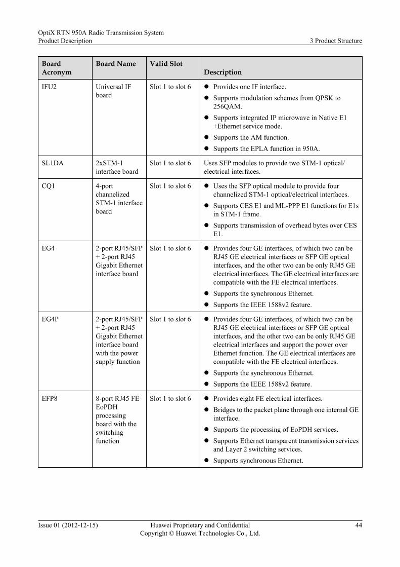
BoardAcronym
Board Name Valid SlotDescription
IFU2 Universal IFboard
Slot 1 to slot 6 l Provides one IF interface.l Supports modulation schemes from QPSK to
256QAM.l Supports integrated IP microwave in Native E1
+Ethernet service mode.l Supports the AM function.l Supports the EPLA function in 950A.
SL1DA 2xSTM-1interface board
Slot 1 to slot 6 Uses SFP modules to provide two STM-1 optical/electrical interfaces.
CQ1 4-portchannelizedSTM-1 interfaceboard
Slot 1 to slot 6 l Uses the SFP optical module to provide fourchannelized STM-1 optical/electrical interfaces.
l Supports CES E1 and ML-PPP E1 functions for E1sin STM-1 frame.
l Supports transmission of overhead bytes over CESE1.
EG4 2-port RJ45/SFP+ 2-port RJ45Gigabit Ethernetinterface board
Slot 1 to slot 6 l Provides four GE interfaces, of which two can beRJ45 GE electrical interfaces or SFP GE opticalinterfaces, and the other two can be only RJ45 GEelectrical interfaces. The GE electrical interfaces arecompatible with the FE electrical interfaces.
l Supports the synchronous Ethernet.l Supports the IEEE 1588v2 feature.
EG4P 2-port RJ45/SFP+ 2-port RJ45Gigabit Ethernetinterface boardwith the powersupply function
Slot 1 to slot 6 l Provides four GE interfaces, of which two can beRJ45 GE electrical interfaces or SFP GE opticalinterfaces, and the other two can be only RJ45 GEelectrical interfaces and support the power overEthernet function. The GE electrical interfaces arecompatible with the FE electrical interfaces.
l Supports the synchronous Ethernet.l Supports the IEEE 1588v2 feature.
EFP8 8-port RJ45 FEEoPDHprocessingboard with theswitchingfunction
Slot 1 to slot 6 l Provides eight FE electrical interfaces.l Bridges to the packet plane through one internal GE
interface.l Supports the processing of EoPDH services.l Supports Ethernet transparent transmission services
and Layer 2 switching services.l Supports synchronous Ethernet.
OptiX RTN 950A Radio Transmission SystemProduct Description 3 Product Structure
Issue 01 (2012-12-15) Huawei Proprietary and ConfidentialCopyright © Huawei Technologies Co., Ltd.
44

BoardAcronym
Board Name Valid SlotDescription
EMS6 4-port RJ45 and2-port SFP FE/GE EoSDHprocessingboard with theswitchingfunction
Slot 1 to slot 6 l Provides four FE electrical interfaces.l Uses SFP modules to provide two GE optical
interfaces or GE electrical interfaces. The GEelectrical interfaces are compatible with the FEelectrical interfaces.
l Bridges to the packet plane through one internal GEinterface.
l Supports the processing of EoSDH services.l Supports Ethernet transparent transmission services
and Layer 2 switching services.l Supports synchronous Ethernet.
ML1 16xE1 (Smart)tributary board
Slot 1 to slot 6 l Provides sixteen 75-ohm or 120-ohm Smart E1interfaces.
l Supports CES E1, ATM/IMA E1, and Fractional E1.
MD1 32xE1 (Smart)tributary board
Slot 1 to slot 6 l Provides thirty-two 75-ohm or 120-ohm Smart E1interfaces.
l Supports CES E1, ATM/IMA E1, and Fractional E1.
SP3S 16xE1 tributaryboard
Slot 1 to slot 6 Provides sixteen 75-ohm or 120-ohm TDM E1interfaces.
SP3D 32xE1 tributaryboard
Slot 1 to slot 6 Provides thirty-two 75-ohm or TDM 120-ohm E1interfaces.
AUX Auxiliaryinterface board
Slot 1 to slot 6 Provides one orderwire interface, one asynchronousdata interface, one synchronous data interface, and four-input and two-output external alarm interfaces.
TCU6 6xE1 connectorconversionboard
Slot 1 to slot 6 Provides one DB44 connector and six RJ45 connectors.When being used with an E1 tributary board and anAnea 96 to DB44 transit cable, it converts E1 interfaces1 to 6 on the Anea 96 connector into RJ45 connectors.
FAN Fan board slot 11 Cools and ventilates the IDU.
3.2.2 ODUThe ODU is an integrated system that is available in several models. The architectures andworking principles of the various ODU models are similar.
OptiX RTN 950A Radio Transmission SystemProduct Description 3 Product Structure
Issue 01 (2012-12-15) Huawei Proprietary and ConfidentialCopyright © Huawei Technologies Co., Ltd.
45

Block Diagram
Figure 3-3 Block diagram of the ODU
Antenna port
CTRL
Tx IF
Rx IF
Cable port
PWR
Up-conversionMultiplexer
O&Muplink
O&Mdownlink
DC
Down-conversion
AMP
LNA
Synthesizers
Duplexer
Rx RF
Tx RF
Signal Processing in the Transmit Direction
The multiplexer splits the signal from the IF cable into a 350 MHz IF signal, a 5.5 MHz O&Muplink signal, and a -48 V DC power signal.
In the transmit direction, the IF signal is processed as follows:
1. After the up-conversion, filtering, and amplification are completed, the IF signal isconverted into the RF signal and then is sent to the AMP amplifier unit.
2. The AMP amplifies the RF signal (the output power of the signal can be controlled by theIDU software).
3. After the amplification, the RF signal is sent to the antenna through the duplexer.
The O&M uplink signal is a 5.5 MHz ASK-modulated signal and is demodulated in the CTRLcontrol unit.
The -48 V DC power signal is sent to the PWR power unit where the secondary power supplythat uses a different voltage is generated and provided to the modules of the ODU.
Signal Processing in the Receive Direction
The duplexer separates the RF signal from the antenna signal. The RF signal is amplified in thelow noise amplifier (LNA). After the down-conversion, filtering, and amplification arecompleted, the RF signal is converted into the 140 MHz IF signal and then is sent to themultiplexer.
The O&M downlink signal is modulated under the ASK scheme in the CTRL unit. The 10 MHzsignal is generated through the modulation and is sent to the multiplexer. The CTRL unit alsodetects the received signal power through the RSSI detection circuit and provides the RSSIinterface.
The IF signal and the O&M downlink signal are combined in the multiplexer and then are sentto the IDU through the IF cable.
OptiX RTN 950A Radio Transmission SystemProduct Description 3 Product Structure
Issue 01 (2012-12-15) Huawei Proprietary and ConfidentialCopyright © Huawei Technologies Co., Ltd.
46

3.3 Software StructureThe OptiX RTN 950A software consists of the NMS software, IDU software, and ODU software.
Functional Block DiagramThe OptiX RTN 950A software consists of IDU software and ODU software, as shown in Figure3-4.
l The OptiX RTN 950A uses Qx interfaces to communicate with the iManager U2000 orWeb LCT. The Qx interfaces are management protocol interfaces designed for Huawei'sOptiX equipment. The protocol stack and messages used by Qx interfaces are developedbased on ITU-T G.773, ITU-T Q.811, and ITU-T Q.812.
l The OptiX RTN 950A provides a Simple Network Management Protocol (SNMP) agent,so a third-party centralized NMS can query alarms, performance events, and manyconfiguration data through SNMP interfaces.
l OptiX NEs send network management messages with each other using the HWECCprotocol or IP protocol.
Figure 3-4 Software architecture
ODU软件
Qxinterface
ODU software
IDUsoftware
NE software
Board software
SNMP
iManager U2000,or Web LCT
Other NEs
HWECC/IP/L2 DCN
NMS side
NE side
Centralizedmonitoring
(OSS)
IDU SoftwareThe IDU software consists of NE software and board software.
l The NE software manages, monitors, and controls the running status of the IDU. Throughthe NE software, the NMS communicates with boards, and manages the NE. The NEsoftware communicates with the ODU software to manage and control the operation of theODU.
OptiX RTN 950A Radio Transmission SystemProduct Description 3 Product Structure
Issue 01 (2012-12-15) Huawei Proprietary and ConfidentialCopyright © Huawei Technologies Co., Ltd.
47

l The board software manages and controls the running status of other boards of the IDUexcept the system control, switching, and timing board. The board software of the Ethernetinterface board or Ethernet processing board is stand-alone and runs board CPU. Softwareof other boards is integrated as software modules with the NE software and runs in the CPUof the system control, switching, and timing board.
ODU SoftwareThe ODU software manages and controls the running status of the ODU. The ODU softwarecontrols the running of the ODU based on the parameters transmitted by the IDU software. TheODU running status is reported to the IDU software.
3.4 Service Signal Processing FlowThe signal processing flows for the SDH microwave, Hybrid microwave, and packet microwaveare different.
3.4.1 SDH MicrowaveThis section describes how an ISU2 board transmits the STM-1 services and the E1 services thatthe CSHO receives. It serves as an example to illustrate the processing flow for SDH microwaveservice signals.
Figure 3-5 Service signal processing flow of the SDH microwave
ISU2 ODU
RFsignal
IFsignal
IDU
Antenna
E1 CSHO
VC-4signal
STM-1
Table 3-3 Service signal processing flow of the SDH microwave in the transmit direction
NO. Component Signal Processing Description
1 CSHO (SDHinterface unit)
l Receives STM-1 signals and performs descrambling.l Processes overheads and pointers.l Demultiplexes VC-4 signals.l Transmits the VC-4 signals to the timeslot cross-connect
unit of the CSHO.
OptiX RTN 950A Radio Transmission SystemProduct Description 3 Product Structure
Issue 01 (2012-12-15) Huawei Proprietary and ConfidentialCopyright © Huawei Technologies Co., Ltd.
48

NO. Component Signal Processing Description
CSHO (tributaryunit)
l Receives E1 signals.l Performs HDB3 decoding.l Maps E1 service signals into VC-12 signals.l Multiplexes the VC-12 signals into VC-4 signals.l Transmits the VC-4 signals to the timeslot cross-connect
unit of the CSHO.
2 CSHO The timeslot cross-connect unit grooms service signals to theVC-4 signals of the ISU2 board.
3 ISU2 l Maps VC-4 signals into STM-1 microwave framepayload, and adds microwave frame overheads andpointers to form complete microwave frames.
l Performs FEC coding.l Performs digital modulation.l Performs D/A conversion.l Performs analog modulation.l Combines the analog IF signals and ODU O&M signals.l Transmits the combined signals and -48 V power to the
ODU through the IF cable.
4 ODU l Splits the analog IF signals, ODU O&M signals, and -48V power.
l Converts the analog IF signals into RF signals through upconversions and amplification.
l Transmits the RF signals to the antenna through thewaveguide.
Table 3-4 Service signal processing flow of the SDH microwave in the receive direction
NO. Component Signal Processing Description
1 ODU l Isolates and filters RF signals.l Converts the RF signals into analog IF signals through
down conversions and amplification.l Combines the IF signals and the ODU O&M signals.l Transmits the combined signals to the IF board through
the IF cable.
OptiX RTN 950A Radio Transmission SystemProduct Description 3 Product Structure
Issue 01 (2012-12-15) Huawei Proprietary and ConfidentialCopyright © Huawei Technologies Co., Ltd.
49

NO. Component Signal Processing Description
2 ISU2 l Splits the received analog IF signals and ODU O&Msignals.
l Performs A/D conversion for the IF signals.l Performs digital demodulation.l Performs time domain adaptive equalization.l Performs FEC decoding.l Synchronizes and descrambles the frames.l Extracts overheads from microwave frames.l Extracts VC-4 signals from the microwave frames, and
transmits the VC-4 signals to the timeslot cross-connectunit of the CSHO.
3 CSHO The timeslot cross-connect unit grooms service signals to theVC-4 signals of the SDH interface unit and tributary unit.
4 CSHO (SDHinterface unit)
l Adds overheads and pointers, and maps VC-4 signals intoSTM-1 signals.
l Performs scrambling and outputs STM-1 signals.
CSHO (tributaryunit)
l Demultiplexes VC-12 signals from VC-4 signals.l Demaps E1 service signals from the VC-12 signals.l Performs HDB3 coding.l Outputs E1 signals.
3.4.2 Hybrid MicrowaveThis section describes how an ISU2 board transmits the E1 services and the FE/GE services thatthe CSHO receives. It serves as an example to illustrate the processing flow for Hybridmicrowave service signals.
Figure 3-6 Service signal processing flow of the Hybrid microwave
E1
CSHO ISU2
IDUVC-4signal
FE/GEEthernet
signal
ODU
RFsignal
IFsignal
Antenna
OptiX RTN 950A Radio Transmission SystemProduct Description 3 Product Structure
Issue 01 (2012-12-15) Huawei Proprietary and ConfidentialCopyright © Huawei Technologies Co., Ltd.
50

Table 3-5 Service signal processing flow of the Hybrid microwave in the transmit direction
NO. Component Signal Processing Description
1 CSHO (tributaryunit)
l Receives E1 signals.l Performs HDB3 decoding.l Maps E1 service signals into VC-12 signals.l Multiplexes the VC-12 signals into VC-4 signals.l Transmits the VC-4 signals to the timeslot cross-connect
unit of the CSHO.
CSHO (Ethernetinterface unit)
l Receives FE/GE signals.l Performs decoding.l Aligns frames, strips preamble codes, and processes CRC
codes.l Forwards Ethernet frames to the packet switching unit of
the CSHO.
2 CSHO l Based on the service configuration, the timeslot cross-connect unit grooms VC-12 signals to the VC-4 signals ofthe ISU2 board.
l The packet switching unit processes Ethernet framesbased on the configuration and the Layer 2 protocol, andthen forwards the processed Ethernet frames to the ISU2through the microwave port.
3 ISU2 l Selects the proper modulation scheme based on the currentchannel quality.
l Demultiplexes the VC-12 signals to be transmitted fromVC-4 signals.
l Demaps E1 service signals from the VC-12 signals.l Maps the E1 service signals and Ethernet frames into the
microwave frame payload, and adds microwave frameoverheads to form complete microwave frames.
l Performs FEC coding.l Performs digital modulation.l Performs D/A conversion.l Performs analog modulationl Combines the analog IF signals and ODU O&M signals.l Transmits the combined signals and -48 V power to the
ODU through the IF cable.
4 ODU l Splits the analog IF signals, ODU O&M signals, and -48V power.
l Converts the analog IF signals into RF signals through upconversions and amplification.
l Transmits the RF signals to the antenna through thewaveguide.
OptiX RTN 950A Radio Transmission SystemProduct Description 3 Product Structure
Issue 01 (2012-12-15) Huawei Proprietary and ConfidentialCopyright © Huawei Technologies Co., Ltd.
51

Table 3-6 Service signal processing flow of the Hybrid microwave in the receive direction
NO. Component Signal Processing Description
1 ODU l Isolates and filters RF signals.l Converts the RF signals into analog IF signals through
down conversions and amplification.l Combines the IF signals and the ODU O&M signals.l Transmits the combined signals to the IF board through
the IF cable.
2 ISU2 l Splits the received analog IF signals and ODU O&Msignals.
l Performs A/D conversion.l Performs digital demodulation.l Performs time domain adaptive equalization.l Performs FEC decoding.l Synchronizes and descrambles the frames.l Extracts overheads from microwave frames.l Extracts E1 service signals from the microwave frames
and maps the E1 service signals into VC-12 signals.l Multiplexes the VC-12 signals into VC-4 signals and
transmits the VC-4 signals to the timeslot cross-connectunit of the CSHO.
l Extracts Ethernet frames from microwave frames, andtransmits the Ethernet frames to the packet switching unitof the CSHO.
3 CSHO l Based on the service configuration, the timeslot cross-connect unit grooms VC-12 signals to the VC-4 signals ofthe tributary unit.
l The packet switching unit processes Ethernet framesbased on the configuration and the Layer 2 protocol, andthen forwards the processed Ethernet frames to theEthernet interface unit.
4 CSHO (tributaryunit)
l Demultiplexes VC-12 signals from VC-4 signals.l Demaps E1 service signals from the VC-12 signals.l Performs HDB3 coding.l Outputs E1 signals.
CSHO (Ethernetinterface unit)
l Aligns frames, adds preamble codes, and processes CRCcodes.
l Performs coding.l Outputs FE/GE signals.
OptiX RTN 950A Radio Transmission SystemProduct Description 3 Product Structure
Issue 01 (2012-12-15) Huawei Proprietary and ConfidentialCopyright © Huawei Technologies Co., Ltd.
52

3.4.3 Packet MicrowaveThis section describes how an ISU2 board transmits the TDM E1 and ATM/IMA E1 servicesthat the ML1 receives, and the FE/GE services that the CSHO receives. It serves as an exampleto illustrate the processing flow for Packet microwave service signals.
Figure 3-7 Flow of service signal processing
ML1
ISU2 ODU
RFsignal
IFsignal
IDU
Antenna
E1
FE/GE
Servicebus
CSHO
Servicebus
Table 3-7 Service signal processing in the transmit direction
NO. Component Signal Processing Description
1 ML1 l Receives TDM E1 signals and ATM/IMA E1 signals.l Extracts service payloads from TDM E1 signals and
performs the PWE3 encapsulation to form the Ethernetframes that carry PW packets.
l Demultiplexes ATM cells from ATM/IMA E1 signals andperforms the PWE3 encapsulation to form the Ethernetframes that carry PW packets.
l Forwards Ethernet frames to the packet switching unit ofthe CSHO.
CSHO (Ethernetinterface unit)
l Receives FE/GE signals.l Performs decoding.l Delimits frames, strips preambles, and processes cyclic
redundancy check (CRC) codes.l Forwards Ethernet frames to the packet switching unit of
the CSHO.
2 CSHO l Performs Layer 2 processing for the Ethernet signals thatare transmitted from the Ethernet interface unit based onthe configuration and the Layer 2 protocol, and thenperforms PWE3 encapsulation to form the Ethernet framesthat carry PW packets.
l Processes the Ethernet frames that carry and isolate PWpackets based on the service configuration and the Layer3 protocol, and then forwards the processed Ethernetframes to ISU2.
OptiX RTN 950A Radio Transmission SystemProduct Description 3 Product Structure
Issue 01 (2012-12-15) Huawei Proprietary and ConfidentialCopyright © Huawei Technologies Co., Ltd.
53

NO. Component Signal Processing Description
3 ISU2 l Selects the proper modulation scheme based on the qualityof the channel.
l Receives the Ethernet signals transmitted from the .l Forms Ethernet service signals and microwave frame
overheads into microwave frames.l Performs FEC coding.l Performs digital modulation.l Performs D/A conversion.l Performs analog modulationl Combines the analog IF signals and ODU O&M signals.l Transmits the combined signals and -48 V power to the
ODU through the IF cable.
4 ODU l Splits the analog IF signals, ODU O&M signals, and -48V power.
l Converts the analog IF signals into RF signals through upconversions and amplification.
l Transmits the RF signals to the antenna through thewaveguide.
Table 3-8 Service signal processing flow in the receive direction
NO. Component Signal Processing Description
1 ODU l Isolates and filters RF signals.l Converts the RF signals into analog IF signals through
down conversions and amplification.l Combines the IF signals and the ODU O&M signals.l Transmits the combined signals to the IF boards.
2 ISU2 l Splits the received analog IF signals and ODU O&Msignals.
l Performs A/D conversion.l Performs digital demodulation.l Performs time domain adaptive equalization.l Performs FEC decoding.l Synchronizes and descrambles the frames.l Extracts overheads from microwave frames.l Extracts Ethernet frames from microwave frames, and
transmits the Ethernet frames to the packet switching unitof the CSHO.
OptiX RTN 950A Radio Transmission SystemProduct Description 3 Product Structure
Issue 01 (2012-12-15) Huawei Proprietary and ConfidentialCopyright © Huawei Technologies Co., Ltd.
54

NO. Component Signal Processing Description
3 CSHO l Processes the Ethernet frames that carry PW packets basedon the service configuration and the Layer 3 protocol, andthen forwards the processed Ethernet frames.
l Forwards Ethernet frames to the ML1 directly. In the caseof the Ethernet frames that need to be forwarded to theEthernet interface unit, extracts Ethernet frames from PWpackets, performs layer 2 processing based on theconfiguration and the Layer 2 protocol, and then forwardsthe Ethernet frames to the Ethernet interface unit.
4 ML1 l Extracts ATM cells, and TDM E1 service payloads fromPW packets.
l Multiplexes the ATM cells into the ATM/IMA E1 signalsinversely.
l Performs HDB3 coding.l Outputs E1 signals.
CSHO (Ethernetinterface unit)
l Delimits frames, adds preambles, and processes CRCcodes.
l Performs coding.l Outputs FE/GE signals.
OptiX RTN 950A Radio Transmission SystemProduct Description 3 Product Structure
Issue 01 (2012-12-15) Huawei Proprietary and ConfidentialCopyright © Huawei Technologies Co., Ltd.
55

4 Networking and Applications
About This Chapter
The OptiX RTN 950A provides complete microwave transmission solutions and supportsvarious types of networking solutions to meet the diverse customer requirements.
4.1 Basic Network Topologies
4.2 Networking with the OptiX RTN 310The OptiX RTN 950A supports power over Ethernet function. It can be cooperated with theOptiX RTN 310 (a full outdoor equipment) directly, and works as service convergence nodes.
4.3 Feature Application (MPLS Packet Service)The MPLS/PWE3 technology allows for the transmission of multiple types of services in packetswitching networks. The OptiX RTN 950A can transmit three types of packet services: CESservices, ATM services, and Ethernet services.
4.4 Feature Application (Traversing the Original Network)When carriers build microwave networks, the original local backhaul networks may not besuitable for transmitting the services carried on microwave networks. In this case, the OptiXRTN 950A can provide features that enable services to traverse the local backhaul networks.
OptiX RTN 950A Radio Transmission SystemProduct Description 4 Networking and Applications
Issue 01 (2012-12-15) Huawei Proprietary and ConfidentialCopyright © Huawei Technologies Co., Ltd.
56

4.1 Basic Network Topologies
4.1.1 Chain NetworkThe OptiX RTN 950A supports a chain network, and can form a tree or star network.
Figure 4-1 shows the radio transmission solution wherein a chain network is the basic networktopology.
l The radio link of a required air interface capacity can be established based on the capacityof an access link. An ordinary link uses 1+0 non-protection configuration. An importantlink uses the 1+1 protection configuration.
l The radio link of a required air interface capacity can be established based on the capacityof the aggregation link, and the radio link uses 1+1 protection configuration
l The radio link uses configuration if protection is not required, which will the servicecapacity between sites.
Figure 4-1 Radio transmission solution based on chain networks
Tail link Feeder link
Regional BackhaulNetwork
BSC
1+1
1+0
1+1E1
FE
FE
E1 RNC
BTS
NodeB
BTS
NodeB
4.1.2 Ring NetworkThe OptiX RTN 950A supports a ring network and provides protection for a ring network. Inaddition, a ring network and a chain network can form a ring with chain network.
l On a ring network comprised of TDM radio links, SNCP can be configured to protect SDH/PDH services.
l On a ring network comprised of Hybrid radio links, SNCP can be configured to protectSDH/PDH services while ERPS can be configured to protect Ethernet services.
OptiX RTN 950A Radio Transmission SystemProduct Description 4 Networking and Applications
Issue 01 (2012-12-15) Huawei Proprietary and ConfidentialCopyright © Huawei Technologies Co., Ltd.
57
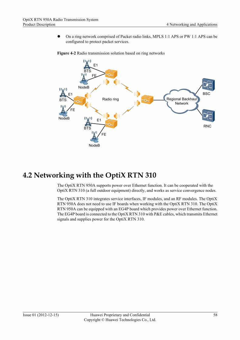
l On a ring network comprised of Packet radio links, MPLS 1:1 APS or PW 1:1 APS can beconfigured to protect packet services.
Figure 4-2 Radio transmission solution based on ring networks
BTSE1
FE
NodeB
Radio ring
BTSE1
FE
BTS
E1
FE
NodeB
Regional BackhaulNetwork
BSC
NodeB
RNC
4.2 Networking with the OptiX RTN 310The OptiX RTN 950A supports power over Ethernet function. It can be cooperated with theOptiX RTN 310 (a full outdoor equipment) directly, and works as service convergence nodes.
The OptiX RTN 310 integrates service interfaces, IF modules, and an RF modules. The OptiXRTN 950A does not need to use IF boards when working with the OptiX RTN 310. The OptiXRTN 950A can be equipped with an EG4P board which provides power over Ethernet function.The EG4P board is connected to the OptiX RTN 310 with P&E cables, which transmits Ethernetsignals and supplies power for the OptiX RTN 310.
OptiX RTN 950A Radio Transmission SystemProduct Description 4 Networking and Applications
Issue 01 (2012-12-15) Huawei Proprietary and ConfidentialCopyright © Huawei Technologies Co., Ltd.
58

Figure 4-3 Networking with the OptiX RTN 310
Aggregation Layer
NodeB
NodeB
NodeB
NodeB
P&E
OptiX RTN 950/980OptiX RTN 310
P&E
Access Layer
RNC
RNC
P&E
P&E
P&E cable
4.3 Feature Application (MPLS Packet Service)The MPLS/PWE3 technology allows for the transmission of multiple types of services in packetswitching networks. The OptiX RTN 950A can transmit three types of packet services: CESservices, ATM services, and Ethernet services.
4.3.1 CES ServicesOn the OptiX RTN 950A, CES services are constructed using the TDM PWE3 technology. Thatis, TDM E1 services are encapsulated into PW packets, and the PW packets are transmittedthrough a PW on the PSN.
Application ExampleCircuit emulation service (CES) is mainly used to transmit mobile backhauled services andenterprise private line services. As shown in Figure 4-4, a 2G base station or an enterprise privateline connects to the OptiX RTN 950A through a TDM line. The OptiX RTN 950A encapsulatesthe TDM signals into packets, and then transmits the packets to the opposite end through a PWon the PSN.
OptiX RTN 950A Radio Transmission SystemProduct Description 4 Networking and Applications
Issue 01 (2012-12-15) Huawei Proprietary and ConfidentialCopyright © Huawei Technologies Co., Ltd.
59

Figure 4-4 Example of CES services
IP/MPLS Backebone Network
BTS BTS
Backebone layer
Convergence layer
Access layer
BSCBSC
CES services OptiX packettransmission product
OptiX RTN 900
BTS BTSCorporation Corporation
Emulation ModesThe OptiX RTN 950A supports CES services in structured emulation mode and non-structuredemulation mode.
l The structured emulation mode is the CESoPSN mode. The equipment is aware of the framestructure, framing mode, and timeslot information in the TDM circuit.
l The non-structured emulation mode is the SAToP mode. The equipment is not aware ofthe frame structure. Instead, the equipment considers the TDM signals as consecutive bitstreams, and then emulates and transparently transmits the TDM signals.
As shown in Figure 4-5, the OptiX RTN 950A in CESoPSN mode supports the compression ofidle 64 kbit/s timeslots in TDM E1 signals to save transmission bandwidth.
OptiX RTN 950A Radio Transmission SystemProduct Description 4 Networking and Applications
Issue 01 (2012-12-15) Huawei Proprietary and ConfidentialCopyright © Huawei Technologies Co., Ltd.
60

Figure 4-5 Compression of idle 64 kbit/s timeslots in TDM E1 signals
BSC
...
0 1
292 3
30 31
...0 1
292 3
30 31
BTS
BTS
BTS
...0 1 292 3 30 31
...0 1 292 3 30 31 Timeslots in the E1 frame
...0 1 292 3 30 31
...0 1 292 3 30 31
...0 1 292 3 30 31
PW1 2 29
PW1 3 30 31
PW1 2 3
Service ClocksClock information is an important feature of TDM services. The OptiX RTN 950A supports theretiming clocks and CES ACR clocks of CES services.
In retiming synchronization mode, the system clocks of all PEs on the network are synchronized.The system clock of a PE is considered as the service transmit clock (retiming). As shown inFigure 4-6, the system clock of BTS synchronizes itself with the service clock of PE. In thismanner, all PEs and CEs are synchronous, and the transmit clocks of TDM services on all CEsand PEs are synchronous.
Figure 4-6 Retiming synchronization mode of CES service clocks
BTS BSCPE PE
CES
E1
Clock synchronization
E1
Synchronizes withthe E1 signal clock.
Synchronizes withthe radio link clock.
Transmits E1signals according tothe system clock.
In ACR mode, the clock is extracted from the TDM interface on the PE on the ingress side. Onthe PE on the egress side, the clock of the emulated TDM service is recovered based on the clockinformation in the CES service. Figure 4-7 shows the retiming synchronization mode of CESservice clocks.
OptiX RTN 950A Radio Transmission SystemProduct Description 4 Networking and Applications
Issue 01 (2012-12-15) Huawei Proprietary and ConfidentialCopyright © Huawei Technologies Co., Ltd.
61

Figure 4-7 Adaptive synchronization mode of CES service clocks
BTS BSCPE PE
CES
E1 E1
Extracts the clock from theE1 signal and add theclock information to theCES service.
Recovers the E1 signalclock from the CESservice.
Clock synchronization
Channelized STM-1 EmulationThe OptiX RTN 950A supports the transparent transmission of STM-1 services in packetnetworks through CES emulation of channelized STM-1 services. As shown in Figure 4-8,section overhead bytes and 63xE1 signals in STM-1 frames can be encapsulated into CESservices for transmission in packet networks.
During channelized STM-1 emulation, line clock synchronization across the SDH network canbe implemented in the following two modes:l The system clock of the OptiX RTN 950A is synchronized with SDH equipment through
SDH line clocks.l The OptiX RTN 950A derives the transmit clock from the receive clock through the line-
clock retiming function. Therefore, the receive clock and transmit clock are synchronouson the SDH equipment.
Figure 4-8 Channelized STM-1 emulation
PacketMW Network
SDH SDH
E1 E1
E1PW
E1xPW
...
OHPW
E1
E1x...
E1
E1x...
E1PW
E1xPW
...
OHPW
SynchronizedLine clock
Retiming
STM-1OH
E1
E1x...
STM-1OH
E1
E1x...
OptiX RTN 950A Radio Transmission SystemProduct Description 4 Networking and Applications
Issue 01 (2012-12-15) Huawei Proprietary and ConfidentialCopyright © Huawei Technologies Co., Ltd.
62

4.3.2 ATM/IMA ServicesThe OptiX RTN 950A supports ATM PWE3 services. The ATM/IMA E1 technology is used totransmit ATM services to the OptiX RTN equipment, and then the ATM cells are encapsulatedinto PW packets. The packets are then transmitted in the MPLS tunnel on the PSN.
Application Example
ATM/IMA services are mainly backhauled services of base stations. With the ATM/IMA E1technology, the ATM services from NodeB are transmitted to the OptiX RTN 950A. On theOptiX RTN 950A, PWE3 emulation is performed for the ATM services. Then, the services aretransmitted over PWs in MPLS tunnels across the PSN towards the RNC. Before being sent tothe RNC, the services are decapsulated on the OptiX PTN/RTN equipment. Figure 4-9 showsthe application example.
Figure 4-9 Example of ATM/IMA services
IMA E1
NodeBRTN PTN
IMA E1/c-STM-1
PSN
MPLS tunnel
RNC
PW (ATM PWE3)
ATM/IMA Services on the UNI Side
On the UNI side, the OptiX RTN 950A supports the following ATM/IMA functions:
l Supports the IMA E1 technology in which an IMA group is comprised of E1 links.
l Supports the Fractional IMA technology in which an IMA group is comprised of FractionalE1 links.
ATM PWE3 Services on the NNI Side
On the NNI side, the OptiX RTN 950A supports the following ATM PWE3 functions:
l One-to-one VCC mapping scheme: One VCC is mapped into one PW.
l N-to-one VCC mapping scheme: N (N≤32) VCCs are mapped into one PW.
l One-to-one VPC mapping scheme: One VPC is mapped into one PW.
l N-to-one VPC mapping scheme: N (N≤32) VPCs are mapped into one PW.
l On one PW, a maximum of 31 ATM cells can be concatenated.
l ATM transparent service.
OptiX RTN 950A Radio Transmission SystemProduct Description 4 Networking and Applications
Issue 01 (2012-12-15) Huawei Proprietary and ConfidentialCopyright © Huawei Technologies Co., Ltd.
63

4.3.3 Ethernet ServicesThe OptiX RTN 950A supports Ethernet PWE3 services. Therefore, PWs can be used to transmitE-Line services and E-Aggr services.
E-Line Services
The E-Line technology is used to transmit isolated Ethernet private line services.
Figure 4-10 illustrates an example of how E-Line services are applied on the OptiX RTN950A. Company A has branches in City 1 and City 3; Company B has branches in City 2 andCity 3; Company C has branches in City 1 and City 2. The branches of Company A, CompanyB, and Company C each have specific data communication requirements. In this applicationscenario, the OptiX RTN 950A can provide E-Line services for Company A, Company B, andCompany C that can meet each of their respective needs while ensuring that the service data ofeach company is separated.
Figure 4-10 Example of E-Line services
Nationwide/Globalcarrier Ethernet
Company A
Company B
City 3
Company C
City 1
Company A
Company C
Company B
City 2
E-Line1E-Line2E-Line3
OptiX RTN 900
OptiX packettransmission product
E-Aggr Services
The E-Aggr technology is used to transmit multipoint-to-point bidirectional aggregationservices. An E-Aggr service has multiple aggregation sources and one aggregation sink. Theaggregation sources and the aggregation sink can communicate with each other bidirectionally,but are isolated from each other.
OptiX RTN 950A Radio Transmission SystemProduct Description 4 Networking and Applications
Issue 01 (2012-12-15) Huawei Proprietary and ConfidentialCopyright © Huawei Technologies Co., Ltd.
64

E-Aggr services are distinguished based on VLAN tag switching. E-ARRG services simplifyservice configuration, and QoS processing can be performed at aggregation points.
Figure 4-10 shows the application of E-Aggr services on a mobile bearer network. On the basestation side, services from different base stations are aggregated to a PW; on the RNC side,services on multiple PWs are aggregated at an interface and then transmitted to the RNC.
Figure 4-11 Example of E-Aggr services
FE
NodeB1
RTN
RTN
RTN
GELSP1/PW1
LSP2/PW2
MPLSnetwork
RNC
NodeB 2
NodeB 3
NodeB 4
FE
FE
FE
GE
UNIs-NNIaggregation
NNIs-UNIaggregation
UNIs-NNIaggregation
VPLS ServicesVirtual private LAN service (VPLS) is a Layer 2 virtual private network (VPN) technology thatprovides multipoint connectivity over a Multiprotocol Label Switching (MPLS) network.
VPLS uses virtual switch instances (VSIs) to enable Layer 2 forwarding. One VPN correspondsto one VSI to which PWs and UNI ports can be mounted. Each VSI maintains a forwarding tablethat includes MAC addresses and their associated PWs or V-UNIs, and forwards traffic basedon table entries. The OptiX RTN 950A can be configured with multiple VSIs to supportcoexistence of multiple VPNs.
Figure 4-12 shows a mobile backhaul network. The NodeBs that belong to the same RNC useVLAN IDs to differentiate services, and they use the same group of VLAN IDs. To isolateservices between the two RNCs (as well as their NodeBs) while enabling VPN communicationbetween each RNC and their NodeBs, you can create two VSIs on the convergence RTN node.
OptiX RTN 950A Radio Transmission SystemProduct Description 4 Networking and Applications
Issue 01 (2012-12-15) Huawei Proprietary and ConfidentialCopyright © Huawei Technologies Co., Ltd.
65

Figure 4-12 Example of VPLS services
FE
NodeBA01
RTN
GELSP1
LSP2
MPLSnetwork
RNC A
NodeBA02
FE
FE
FE
GE
RNC B
NodeBB01
NodeBB02
GE
RTN
RTN
Router
VSI
4.4 Feature Application (Traversing the Original Network)When carriers build microwave networks, the original local backhaul networks may not besuitable for transmitting the services carried on microwave networks. In this case, the OptiXRTN 950A can provide features that enable services to traverse the local backhaul networks.
4.4.1 Traversing a TDM Network by Using the EoPDH/EoSDHFeature
The EoPDH/EoSDH feature provides a solution that transmits Ethernet services over E1 signalsso that carriers can transmit Ethernet services on the existing TDM networks.
In most cases, a new radio access network transmits the Ethernet services from 3G base stationsin Native mode over the Integrated IP radio links, but a large number of TDM networks existon the local backhaul network at the convergence layer; therefore, Ethernet service cannot bedirectly transmitted. In this case, the OptiX RTN 950A at the convergence node of microwaveservices can use the EoPDH/EoSDH feature to transmit Ethernet services.
The EoPDH/EoSDH feature is used to encapsulate the Ethernet services on the Integrated IPradio links or the Ethernet services locally added into E1 signals. The feature then transmits theEthernet services over the existing TDM networks. At the last node on the TDM network, theMSTP or RTN equipment that supports the EoPDH/EoSDH feature is used to decapsulate theEthernet services for transmission. For details, see Figure 4-13.
OptiX RTN 950A Radio Transmission SystemProduct Description 4 Networking and Applications
Issue 01 (2012-12-15) Huawei Proprietary and ConfidentialCopyright © Huawei Technologies Co., Ltd.
66

Figure 4-13 Traversing a TDM network using the EoPDH/EoSDH feature
FE
FERNC
TDM BackhaulNetwork
EthernetE1/STM-1
EthernetIP MW
EthernetE1/STM-1
NodeB
NodeB
FE
NodeB
EthernetFE
EthernetFE
EthernetFE/GE
E1/STM-1 FE/GERTN
RTN
RTN
MSTP
4.4.2 Using ML-PPP to Transmit Services Through a TDM NetworkThe multilink PPP (ML-PPP) technology is a solution in which E1 is used to bear MPLS tunnels.Using ML-PPP, carriers can transmit packet services through the existing TDM network.
During the evolution to packet backhaul networks, base station services received through E1,ATM/IMA, or FE/GE interfaces are backhauled as packet services by using the MPLS/PWE3technology. However, legacy TDM-based backhaul networks or TDM leased lines cannotbackhaul packet services directly. Packet backhaul can be implemented by using the ML-PPPfunction on OptiX RTN 950A, the convergence node of microwave services. The ML-PPPfunction bundles multiple E1s into an ML-PPP group to carry MPLS tunnels and backhaul packetservices. E1 channels on CQ1, a channelized STM-1 board, can also be bundled into an ML-PPP group.
As shown in Figure 4-14, ML-PPP helps the equipment to encapsulate the packet services onthe Hybrid radio links or the Ethernet services locally added into E1 signals and then to transmitthe Ethernet services over the existing TDM networks. After the services traverse a TDMnetwork, the OptiX PTN equipment (or OptiX RTN equipment) decapsulates Ethernet servicesbefore transmission.
OptiX RTN 950A Radio Transmission SystemProduct Description 4 Networking and Applications
Issue 01 (2012-12-15) Huawei Proprietary and ConfidentialCopyright © Huawei Technologies Co., Ltd.
67

Figure 4-14 Using ML-PPP to transmit services through a TDM network
FE
FERNC
TDM BackhaulNetwork
EthernetIP MW
NodeB
NodeB
FE
NodeB
EthernetFE
EthernetFE
EthernetFE/GE
E1/c-STM-1 FE/
GERTN
RTN
RTN
PTN
EthernetMPLS
ML-PPPPPPE1
EthernetMPLS
ML-PPPPPPE1
E1/c-STM-1
4.4.3 Traversing a Layer 2 Network by Using VLAN Sub-interfacesThe method of adding VLAN IDs to MPLS tunnels enables the MPLS tunnels to traverse a Layer2 network. This means that carriers can use their live Layer 2 networks to transmit packetservices.
Generally, all NEs that an LSP traverses support MPLS. In certain circumstances, however,LSPs need to traverse a Layer 2 network (such as a metropolitan Ethernet network) that doesnot support MPLS. As shown in Figure 4-15, BTSs and NodeBs are located at the same site,and they transmit services to the BSC and RNC by using the MPLS or PWE3 technology. Theseservices are transmitted to the Layer 2 network separately. The BSC and RNC are located atdifferent convergence sites. In this scenario, the VLAN sub-interface technology can be used tocreate sub-interfaces with different VLAN IDs on an Ethernet port, therefore adding VLAN IDsto Ethernet frames that carry these LSPs. (LSPs and VLAN IDs have one-to-one mappings.)Within the Layer 2 network, services are transmitted based on VLAN IDs rather than MPLS,enabling LSPs to traverse the Layer 2 network.
OptiX RTN 950A Radio Transmission SystemProduct Description 4 Networking and Applications
Issue 01 (2012-12-15) Huawei Proprietary and ConfidentialCopyright © Huawei Technologies Co., Ltd.
68

Figure 4-15 MPLS tunnels traversing a Layer 2 network using VLAN sub-interfaces
E1BTS
IMA E1RTN
RTN RTNRTN/PTN
RTN/PTN
E1/STM-1
IMA E1/c-STM-1
TDM PWE3
ATM PWE3
Layer2 switchnetwork
RNC
BSC
VLAN 101
VLAN 201LSP 1RTN
LSP 2
NodeB
E1BTS
NodeB
VLAN 102
VLAN 202
VLAN 201
VLAN 202
VLAN 101
VLAN 102
IMA E1
OptiX RTN 950A Radio Transmission SystemProduct Description 4 Networking and Applications
Issue 01 (2012-12-15) Huawei Proprietary and ConfidentialCopyright © Huawei Technologies Co., Ltd.
69
5 Network Management System
About This Chapter
This chapter describes the network management solution and the NMS software that constitutesthis solution.
5.1 Network Management SolutionHuawei offers a complete transmission network management solution compliant with TMN fordifferent function domains and customer groups on telecommunication networks.
5.2 Web LCTThe Web LCT is a local maintenance terminal. The Web LCT provides the followingmanagement functions at the NE layer: NE management, alarm management, performancemanagement, configuration management, communication management, and securitymanagement.
5.3 U2000The U2000 is a network-level network management system. A user can access the U2000 serverthrough a U2000 client to manage Huawei transport subnets in a unified manner. The U2000can provide NE-level and network-level management functions.
OptiX RTN 950A Radio Transmission SystemProduct Description 5 Network Management System
Issue 01 (2012-12-15) Huawei Proprietary and ConfidentialCopyright © Huawei Technologies Co., Ltd.
70

5.1 Network Management SolutionHuawei offers a complete transmission network management solution compliant with TMN fordifferent function domains and customer groups on telecommunication networks.
The NM solutions consist of the following:
l iManager U2000 Web LCT local maintenance terminalThe Web LCT, a Web-based local maintenance terminal, is used to manage local and remoteNEs on a per-site or hop basis.
l iManager U2000 unified network management systemThe iManager U2000, a network-level management system, is used to manage Huaweitransmission equipment such as the OptiX RTN, PTN, MSTP, and WDM equipment.
Figure 5-1 Network management solution for transmission networks
WAN/LAN
iManager U2000
Web LCT Web LCT
Accesslayer
Aggregationlayer
Backbonelayer
5.2 Web LCTThe Web LCT is a local maintenance terminal. The Web LCT provides the followingmanagement functions at the NE layer: NE management, alarm management, performance
OptiX RTN 950A Radio Transmission SystemProduct Description 5 Network Management System
Issue 01 (2012-12-15) Huawei Proprietary and ConfidentialCopyright © Huawei Technologies Co., Ltd.
71
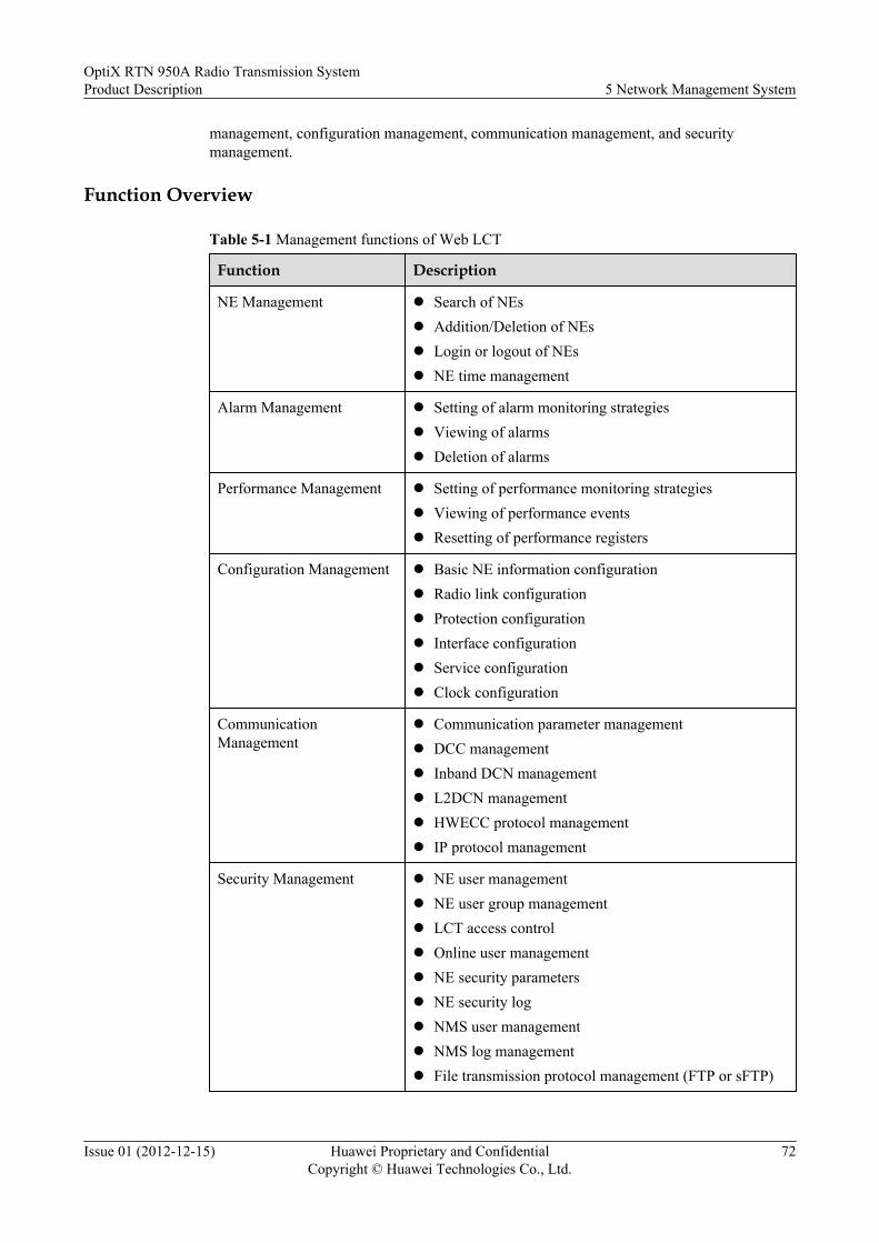
management, configuration management, communication management, and securitymanagement.
Function Overview
Table 5-1 Management functions of Web LCT
Function Description
NE Management l Search of NEsl Addition/Deletion of NEsl Login or logout of NEsl NE time management
Alarm Management l Setting of alarm monitoring strategiesl Viewing of alarmsl Deletion of alarms
Performance Management l Setting of performance monitoring strategiesl Viewing of performance eventsl Resetting of performance registers
Configuration Management l Basic NE information configurationl Radio link configurationl Protection configurationl Interface configurationl Service configurationl Clock configuration
CommunicationManagement
l Communication parameter managementl DCC managementl Inband DCN managementl L2DCN managementl HWECC protocol managementl IP protocol management
Security Management l NE user managementl NE user group managementl LCT access controll Online user managementl NE security parametersl NE security logl NMS user managementl NMS log managementl File transmission protocol management (FTP or sFTP)
OptiX RTN 950A Radio Transmission SystemProduct Description 5 Network Management System
Issue 01 (2012-12-15) Huawei Proprietary and ConfidentialCopyright © Huawei Technologies Co., Ltd.
72

Function Description
HOP Management l Parameters on both ends of a hop can be set on the sameinterface.
l After the parameters on one end of a hop are set, theparameters on the other end are assigned valuesaccordingly.
5.3 U2000The U2000 is a network-level network management system. A user can access the U2000 serverthrough a U2000 client to manage Huawei transport subnets in a unified manner. The U2000can provide NE-level and network-level management functions.
Function Overview
Table 5-2 Management Functions of U2000
Functional Module Description
NE level management l NE panel browsingl Built-in NE manager implementing all-around
network-level management
Networklevelmanagement
Topologymanagement
l Physical topology viewl End-to-end topology management of servicesl Clock viewl Automatic topology discoveryl Customized topology viewl Backup gateway configuration
Network-level alarmmanagement
l Networkwide alarm monitoring, statistics, andmanagement
l Customized alarm query templatesl Alarm correlation analysisl Alarm time localizationl Alarm notificationl Alarm dumping
OptiX RTN 950A Radio Transmission SystemProduct Description 5 Network Management System
Issue 01 (2012-12-15) Huawei Proprietary and ConfidentialCopyright © Huawei Technologies Co., Ltd.
73

Functional Module Description
Network-levelperformancemanagement
l Creation of performance monitoring templatesl Scheduled monitoring and real-time monitoringl Browsing of historical performance datal Graphic display of performance datal Comparison of performance data in different
periods or based on different resourcesl Historical performance data dump
Network-levelconfigurationmanagement
l End-to-end configuration of TDM servicesl End-to-end configuration of MPLS tunnels and
PWE3 servicesl End-to-end configuration of Native E-Line/E-
LAN services
Network-leveldiagnosis and test
l One-click connectivity test of packet servicesl One-click performance test of packet servicesl One-click smart diagnosis of packet service faults
Network-levelcommunicationmanagement
l DCC view managementl Inter-NE Ping and Traceroute tests
Network-levelsecurity management
l Account policy managementl User group managementl Rights managementl RADIUS authentication on user rightsl SSLv3 encrypted communication between U2000
server and U2000 clientl SSLv3 encrypted communication between U2000
server and gateway NEl Access Control List (ACL) management of the
U2000 serverl Access Control List (ACL) management of the
gateway NE
Inventory management l Inventory management of equipment such as NEs,boards, and ports
l Inventory management of fibers and links
Log management l Management of NMS operation logs, system logs,and security logs
l NE Security Log managementl NE Syslog management
OptiX RTN 950A Radio Transmission SystemProduct Description 5 Network Management System
Issue 01 (2012-12-15) Huawei Proprietary and ConfidentialCopyright © Huawei Technologies Co., Ltd.
74

Functional Module Description
Database management l NMS database backup and restorationl NE database backup and restorationl Synchronization between NE data and NMS data
NE Software management l NE software loading and upgradingl NE Software database managementl NE data saving, backup, and restoration
Report management l Management of alarm reports, log reports, andresource reports
l Viewing reports by using Internet Explorerl Output of report files
Northbound interface l SNMP, CORBA, and XML northbound interfacesl Performance text interfaces
OptiX RTN 950A Radio Transmission SystemProduct Description 5 Network Management System
Issue 01 (2012-12-15) Huawei Proprietary and ConfidentialCopyright © Huawei Technologies Co., Ltd.
75

6 Technical Specifications
About This Chapter
This chapter describes the technical specifications of the OptiX RTN 950A.
6.1 RF PerformanceThis chapter describes the radio frequency (RF) performance and various technicalspecifications related to microwaves.
6.2 Predicted Equipment ReliabilityPredicted equipment reliability includes predicted component reliability and predicted linkreliability. Equipment reliability is measured by mean time between failures (MTBF), andpredicated equipment reliability complies with the Telcordia SR-332 standard.
6.3 Interface PerformanceThis section describes the technical specifications of services and auxiliary interfaces.
6.4 Clock Timing and Synchronization PerformanceThe clock timing performance and synchronization performance of the product meet relevantITU-T recommendations.
6.5 Integrated System PerformanceIntegrated system performance includes the dimensions, weight, power consumption, powersupply, EMC, surge protection, safety, and environment.
OptiX RTN 950A Radio Transmission SystemProduct Description 6 Technical Specifications
Issue 01 (2012-12-15) Huawei Proprietary and ConfidentialCopyright © Huawei Technologies Co., Ltd.
76

6.1 RF PerformanceThis chapter describes the radio frequency (RF) performance and various technicalspecifications related to microwaves.
6.1.1 Microwave Work ModesThis section lists the microwave work modes that the OptiX RTN 950A supports base on IFboards.
6.1.1.1 Microwave Work Modes (IFU2 board)
The IFU2 board supports Integrated IP microwave work modes.
NOTE
The channel spacings supported by the OptiX RTN 950A comply with ETSI standards. Channel spacings14/28/56 MHz apply to most frequency bands; but channel spacings 13.75/27.5/55 MHz apply to the 18 GHzfrequency band.
Table 6-1 Integrated IP microwave work modes (IFU2 board)
Channel Spacing(MHz)
ModulationScheme
MaximumNumber of E1s inHybridMicrowave
Native EthernetThroughput(Mbit/s)
7 QPSK 5 9 to 12
7 16QAM 10 20 to 24
7 32QAM 12 24 to 29
7 64QAM 15 31 to 37
7 128QAM 18 37 to 44
7 256QAM 21 43 to 51
14 (13.75) QPSK 10 20 to 23
14 (13.75) 16QAM 20 41 to 48
14 (13.75) 32QAM 24 50 to 59
14 (13.75) 64QAM 31 65 to 76
14 (13.75) 128QAM 37 77 to 90
14 (13.75) 256QAM 43 90 to 104
28 (27.5) QPSK 20 41 to 48
28 (27.5) 16QAM 40 82 to 97
OptiX RTN 950A Radio Transmission SystemProduct Description 6 Technical Specifications
Issue 01 (2012-12-15) Huawei Proprietary and ConfidentialCopyright © Huawei Technologies Co., Ltd.
77

Channel Spacing(MHz)
ModulationScheme
MaximumNumber of E1s inHybridMicrowave
Native EthernetThroughput(Mbit/s)
28 (27.5) 32QAM 52 108 to 125
28 (27.5) 64QAM 64 130 to 150
28 (27.5) 128QAM 75 160 to 180
28 (27.5) 256QAM 75 180 to 210
56 (55) QPSK 40 82 to 97
56 (55) 16QAM 75 165 to 190
56 (55) 32QAM 75 208 to 240
56 (55) 64QAM 75 260 to 310
56 (55) 128QAM 75 310 to 360
56 (55) 256QAM 75 360 to 420
NOTE
For the integrated IP microwave work mode that the IFU2 board supports:
l The throughput specifications listed in the tables are based on untagged Ethernet frames with a lengthranging from 64 bytes to 1518 bytes
l E1 services need to occupy the corresponding bandwidth of the air interface capacity. The bandwidthremaining after the E1 service capacity is subtracted from the air interface capacity can be providedfor Ethernet services.
6.1.1.2 Microwave Work Modes (ISU2 board)
The ISU2 board supports SDH microwave work modes and Integrated IP microwave workmodes.
NOTE
The channel spacings supported by the OptiX RTN 950A comply with ETSI standards. Channel spacings14/28/56 MHz apply to most frequency bands; but channel spacings 13.75/27.5/55 MHz apply to the 18 GHzfrequency band.
SDH Microwave Work Modes
Table 6-2 SDH microwave work modes (ISU2 board)
Service Capacity Modulation Scheme Channel Spacing (MHz)
STM-1 128QAM 28 (27.5)
2xSTM-1 128QAM 56 (55)
OptiX RTN 950A Radio Transmission SystemProduct Description 6 Technical Specifications
Issue 01 (2012-12-15) Huawei Proprietary and ConfidentialCopyright © Huawei Technologies Co., Ltd.
78

Service Capacity Modulation Scheme Channel Spacing (MHz)
2xSTM-1 256QAM 50
Integrated IP Microwave Work Modes
Table 6-3 Integrated IP microwave work modes (ISU2, E1 + Ethernet)
ChannelSpacing(MHz)
ModulationScheme
MaximumNumber ofE1s inHybridMicrowave
Native Ethernet Throughput (Mbit/s)
WithoutCompression
With L2FrameHeaderCompression
With L2+L3FrameHeaderCompression (IPv4)
With L2+L3FrameHeaderCompression (IPv6)
3.5 QPSK 2 4 to 5 4 to 6 4 to 6 4 to 10
3.5 16QAM 4 9 to 11 9 to 13 9 to 13 9 to 20
7 QPSK 5 10 to 13 10 to 15 10 to 22 10 to 33
7 16QAM 10 20 to 26 20 to 30 20 to 44 20 to 66
7 32QAM 12 25 to 32 25 to 36 25 to 54 25 to 80
7 64QAM 15 31 to 40 31 to 47 31 to 67 31 to 100
7 128QAM 18 37 to 47 37 to 56 37 to 80 37 to 119
7 256QAM 20 41 to 53 41 to 62 41 to 90 42 to 134
14 (13.75) QPSK 10 20 to 26 20 to 31 20 to 44 20 to 66
14 (13.75) 16QAM 20 41 to 52 41 to 61 41 to 89 41 to 132
14 (13.75) 32QAM 24 51 to 65 51 to 77 51 to 110 51 to 164
14 (13.75) 64QAM 31 65 to 83 65 to 96 65 to 140 65 to 209
14 (13.75) 128QAM 37 76 to 97 76 to 113 76 to 165 76 to 245
14 (13.75) 256QAM 42 87 to 111 87 to 131 87 to 189 88 to 281
28 (27.5) QPSK 20 41 to 52 41 to 62 41 to 89 41 to 132
28 (27.5) 16QAM 40 82 to 105 82 to 124 82 to 178 83 to 265
28 (27.5) 32QAM 52 107 to 136 107 to 161 107 to 230 107 to 343
28 (27.5) 64QAM 64 131 to 168 131 to 198 131 to 283 132 to 424
28 (27.5) 128QAM 75 155 to 198 155 to 233 155 to 333 156 to 495
28 (27.5) 256QAM 75 181 to 230 181 to 272 181 to 388 182 to 577
56 (55) QPSK 40 82 to 105 82 to 124 82 to 178 83 to 265
OptiX RTN 950A Radio Transmission SystemProduct Description 6 Technical Specifications
Issue 01 (2012-12-15) Huawei Proprietary and ConfidentialCopyright © Huawei Technologies Co., Ltd.
79

ChannelSpacing(MHz)
ModulationScheme
MaximumNumber ofE1s inHybridMicrowave
Native Ethernet Throughput (Mbit/s)
WithoutCompression
With L2FrameHeaderCompression
With L2+L3FrameHeaderCompression (IPv4)
With L2+L3FrameHeaderCompression (IPv6)
56 (55) 16QAM 75 166 to 212 166 to 250 165 to 356 167 to 533
56 (55) 32QAM 75 206 to 262 206 to 308 206 to 437 207 to 659
56 (55) 64QAM 75 262 to 333 262 to 388 262 to 567 264 to 836
56 (55) 128QAM 75 309 to 396 309 to 466 309 to 656 311 to 983
56 (55) 256QAM 75 360 to 456 360 to 538 360 to 777 362 to 1000
40 QPSK 27 56 to 72 56 to 84 56 to 122 57 to 182
40 16QAM 55 114 to 145 114 to 172 114 to 247 114 to 366
40 32QAM 71 147 to 187 147 to 221 147 to 318 148 to 474
40 64QAM 75 181 to 230 181 to 272 181 to 388 182 to 583
40 128QAM 75 215 to 272 215 to 323 215 to 456 216 to 691
40 256QAM 75 249 to 318 249 to 375 249 to 538 251 to 800
50 QPSK 35 73 to 92 73 to 107 73 to 153 73 to 235
50 16QAM 71 148 to 186 148 to 216 148 to 309 148 to 473
50 32QAM 75 191 to 240 191 to 278 191 to 398 191 to 610
50 64QAM 75 235 to 295 235 to 340 235 to 490 235 to 750
50 128QAM 75 275 to 345 275 to 400 275 to 570 275 to 875
50 256QAM 75 317 to 396 317 to 459 317 to 659 317 to 1000
Table 6-4 Integrated IP microwave work modes (ISU2 board, Native STM-1 + Ethernet service)
ChannelSpacing(MHz)
ModulationScheme
Number ofSTM-1Services inHybridMicrowave
Native Ethernet Throughput (Mbit/s)
WithoutCompression
With L2FrameHeaderCompression
With L2+L3FrameHeaderCompression (IPv4)
With L2+L3FrameHeaderCompression (IPv6)
28 (27.5) 128QAM 1 155 to 198 155 to 233 155 to 333 156 to 495
28 (27.5) 256QAM 1 181 to 230 181 to 272 181 to 388 182 to 577
40 64QAM 1 181 to 230 181 to 272 181 to 388 182 to 583
OptiX RTN 950A Radio Transmission SystemProduct Description 6 Technical Specifications
Issue 01 (2012-12-15) Huawei Proprietary and ConfidentialCopyright © Huawei Technologies Co., Ltd.
80

ChannelSpacing(MHz)
ModulationScheme
Number ofSTM-1Services inHybridMicrowave
Native Ethernet Throughput (Mbit/s)
WithoutCompression
With L2FrameHeaderCompression
With L2+L3FrameHeaderCompression (IPv4)
With L2+L3FrameHeaderCompression (IPv6)
40 128QAM 1 215 to 272 215 to 323 215 to 456 216 to 691
40 256QAM 1 249 to 318 249 to 375 249 to 538 251 to 800
50 32QAM 1 191 to 240 191 to 278 191 to 398 191 to 610
50 64QAM 1 235 to 295 235 to 340 235 to 490 235 to 750
50 128QAM 1 275 to 345 275 to 400 275 to 570 275 to 875
50 256QAM 1 317 to 396 317 to 459 317 to 659 317 to 1000
56 (55) 16QAM 1 166 to 212 166 to 250 165 to 356 167 to 533
56 (55) 32QAM 1 206 to 262 206 to 308 206 to 437 207 to 659
56 (55) 64QAM 1 262 to 333 262 to 388 262 to 567 264 to 836
56 (55) 128QAM 1 309 to 396 309 to 466 309 to 656 311 to 983
56 (55) 256QAM 1 360 to 456 360 to 538 360 to 777 362 to 1000
NOTE
For the integrated IP microwave work mode that the ISU2/ISX2 board supports:
l The throughput specifications listed in the tables are based on the following conditions.
l Without compression: untagged Ethernet frames with a length ranging from 64 bytes to 9600 bytes
l With L2 frame header compression: untagged Ethernet frames with a length ranging from 64 bytes to9600 bytes
l With L2+L3 frame header compression (IPv4): UDP messages, untagged Ethernet frames with a lengthranging from 64 bytes to 9600 bytes
l With L2+L3 frame header compression (IPv6): UDP messages, S-tagged Ethernet frames with a lengthranging from 92 bytes to 9600 bytes
l E1/STM-1 services need to occupy the corresponding bandwidth of the air interface capacity. The bandwidthremaining after the E1/STM-1 service capacity is subtracted from the air interface capacity can be providedfor Ethernet services.
6.1.1.3 Microwave Work Modes (ISX2 board)
The ISX2 board supports SDH microwave work modes and Integrated IP microwave workmodes.
NOTE
The channel spacings supported by the OptiX RTN 950A comply with ETSI standards. Channel spacings14/28/56 MHz apply to most frequency bands; but channel spacings 13.75/27.5/55 MHz apply to the 18 GHzfrequency band.
OptiX RTN 950A Radio Transmission SystemProduct Description 6 Technical Specifications
Issue 01 (2012-12-15) Huawei Proprietary and ConfidentialCopyright © Huawei Technologies Co., Ltd.
81

SDH Microwave Work Modes
Table 6-5 SDH microwave work modes (ISX2 board@IS2-mode)
Service Capacity Modulation Scheme Channel Spacing (MHz)
STM-1 128QAM 28 (27.5)
2xSTM-1 128QAM 56 (55)
2xSTM-1 256QAM 50
NOTEFor the ISX2 board in SDH service mode, the microwave work modes are the same regardless of whetherthe XPIC function is enabled or disabled.
Integrated IP Microwave Work Modes
Table 6-6 Integrated IP microwave work modes (ISX2 board, E1 + Ethernet service, XPIC disabled)
ChannelSpacing(MHz)
ModulationScheme
MaximumNumber ofE1s inHybridMicrowave
Native Ethernet Throughput (Mbit/s)
WithoutCompression
With L2FrameHeaderCompression
With L2+L3FrameHeaderCompression (IPv4)
With L2+L3FrameHeaderCompression (IPv6)
7 QPSK 5 10 to 13 10 to 15 10 to 22 10 to 33
7 16QAM 10 20 to 26 20 to 30 20 to 44 20 to 66
7 32QAM 12 25 to 32 25 to 36 25 to 54 25 to 80
7 64QAM 15 31 to 40 31 to 47 31 to 67 31 to 100
7 128QAM 18 37 to 47 37 to 56 37 to 80 37 to 119
7 256QAM 20 41 to 53 41 to 62 41 to 90 42 to 134
14 (13.75) QPSK 10 20 to 26 20 to 31 20 to 44 20 to 66
14 (13.75) 16QAM 20 41 to 52 41 to 61 41 to 89 41 to 132
14 (13.75) 32QAM 24 51 to 65 51 to 77 51 to 110 51 to 164
14 (13.75) 64QAM 31 65 to 83 65 to 96 65 to 140 65 to 209
14 (13.75) 128QAM 37 76 to 97 76 to 113 76 to 165 76 to 245
14 (13.75) 256QAM 42 87 to 111 87 to 131 87 to 189 88 to 281
28 (27.5) QPSK 20 41 to 52 41 to 62 41 to 89 41 to 132
28 (27.5) 16QAM 40 82 to 105 82 to 124 82 to 178 83 to 265
OptiX RTN 950A Radio Transmission SystemProduct Description 6 Technical Specifications
Issue 01 (2012-12-15) Huawei Proprietary and ConfidentialCopyright © Huawei Technologies Co., Ltd.
82

ChannelSpacing(MHz)
ModulationScheme
MaximumNumber ofE1s inHybridMicrowave
Native Ethernet Throughput (Mbit/s)
WithoutCompression
With L2FrameHeaderCompression
With L2+L3FrameHeaderCompression (IPv4)
With L2+L3FrameHeaderCompression (IPv6)
28 (27.5) 32QAM 52 107 to 136 107 to 161 107 to 230 107 to 343
28 (27.5) 64QAM 64 131 to 168 131 to 198 131 to 283 132 to 424
28 (27.5) 128QAM 75 155 to 198 155 to 233 155 to 333 156 to 495
28 (27.5) 256QAM 75 181 to 230 181 to 272 181 to 388 182 to 577
56 (55) QPSK 40 82 to 105 82 to 124 82 to 178 83 to 265
56 (55) 16QAM 75 166 to 212 166 to 250 165 to 356 167 to 533
56 (55) 32QAM 75 206 to 262 206 to 308 206 to 437 207 to 659
56 (55) 64QAM 75 262 to 333 262 to 388 262 to 567 264 to 836
56 (55) 128QAM 75 309 to 396 309 to 466 309 to 656 311 to 983
56 (55) 256QAM 75 360 to 456 360 to 538 360 to 777 362 to 1000
40 QPSK 27 56 to 72 56 to 84 56 to 122 57 to 182
40 16QAM 55 114 to 145 114 to 172 114 to 247 114 to 366
40 32QAM 71 147 to 187 147 to 221 147 to 318 148 to 474
40 64QAM 75 181 to 230 181 to 272 181 to 388 182 to 583
40 128QAM 75 215 to 272 215 to 323 215 to 456 216 to 691
40 256QAM 75 249 to 318 249 to 375 249 to 538 251 to 800
50 QPSK 35 73 to 92 73 to 107 73 to 153 73 to 235
50 16QAM 71 148 to 186 148 to 216 148 to 309 148 to 473
50 32QAM 75 191 to 240 191 to 278 191 to 398 191 to 610
50 64QAM 75 235 to 295 235 to 340 235 to 490 235 to 750
50 128QAM 75 275 to 345 275 to 400 275 to 570 275 to 875
50 256QAM 75 317 to 396 317 to 459 317 to 659 317 to 1000
OptiX RTN 950A Radio Transmission SystemProduct Description 6 Technical Specifications
Issue 01 (2012-12-15) Huawei Proprietary and ConfidentialCopyright © Huawei Technologies Co., Ltd.
83

Table 6-7 Integrated IP microwave work modes (ISX2, E1 + Ethernet, XPIC enabled)
ChannelSpacing(MHz)
ModulationScheme
MaximumNumber ofE1s inHybridMicrowave
Native Ethernet Throughput (Mbit/s)
WithoutCompression
With L2FrameHeaderCompression
With L2+L3FrameHeaderCompression (IPv4)
With L2+L3FrameHeaderCompression (IPv6)
7 QPSK 4 10 to 13 10 to 15 10 to 22 10 to 33
7 16QAM 9 20 to 26 20 to 30 20 to 44 20 to 66
7 32QAM 11 25 to 32 25 to 36 25 to 54 25 to 80
7 64QAM 14 31 to 40 31 to 47 31 to 67 31 to 100
14 (13.75) QPSK 9 20 to 26 20 to 31 20 to 44 20 to 66
14 (13.75) 16QAM 19 41 to 52 41 to 61 41 to 89 41 to 132
14 (13.75) 32QAM 24 51 to 65 51 to 77 51 to 110 51 to 164
14 (13.75) 64QAM 30 65 to 83 65 to 96 65 to 140 65 to 209
14 (13.75) 128QAM 36 76 to 97 76 to 113 76 to 165 76 to 245
28 (27.5) QPSK 20 41 to 52 41 to 62 41 to 89 41 to 132
28 (27.5) 16QAM 40 82 to 105 82 to 124 82 to 178 83 to 265
28 (27.5) 32QAM 52 107 to 136 107 to 161 107 to 230 107 to 343
28 (27.5) 64QAM 64 131 to 168 131 to 198 131 to 283 132 to 424
28 (27.5) 128QAM 75 155 to 198 155 to 233 155 to 333 156 to 495
28 (27.5) 256QAM 75 181 to 230 181 to 272 181 to 388 182 to 577
56 (55) QPSK 40 82 to 105 82 to 124 82 to 178 83 to 265
56 (55) 16QAM 75 166 to 212 166 to 250 165 to 356 167 to 533
56 (55) 32QAM 75 206 to 262 206 to 308 206 to 437 207 to 659
56 (55) 64QAM 75 262 to 333 262 to 388 262 to 567 264 to 836
56 (55) 128QAM 75 309 to 396 309 to 466 309 to 656 311 to 983
56 (55) 256QAM 75 360 to 456 360 to 538 360 to 777 362 to 1000
40 QPSK 27 56 to 72 56 to 84 56 to 122 57 to 182
40 16QAM 55 114 to 145 114 to 172 114 to 247 114 to 366
40 32QAM 71 147 to 187 147 to 221 147 to 318 148 to 474
40 64QAM 75 181 to 230 181 to 272 181 to 388 182 to 583
40 128QAM 75 215 to 272 215 to 323 215 to 456 216 to 691
OptiX RTN 950A Radio Transmission SystemProduct Description 6 Technical Specifications
Issue 01 (2012-12-15) Huawei Proprietary and ConfidentialCopyright © Huawei Technologies Co., Ltd.
84

ChannelSpacing(MHz)
ModulationScheme
MaximumNumber ofE1s inHybridMicrowave
Native Ethernet Throughput (Mbit/s)
WithoutCompression
With L2FrameHeaderCompression
With L2+L3FrameHeaderCompression (IPv4)
With L2+L3FrameHeaderCompression (IPv6)
40 256QAM 75 249 to 318 249 to 375 249 to 538 251 to 800
50 QPSK 35 73 to 92 73 to 107 73 to 153 73 to 235
50 16QAM 71 148 to 186 148 to 216 148 to 309 148 to 473
50 32QAM 75 191 to 240 191 to 278 191 to 398 191 to 610
50 64QAM 75 235 to 295 235 to 340 235 to 490 235 to 750
50 128QAM 75 275 to 345 275 to 400 275 to 570 275 to 875
50 256QAM 75 317 to 396 317 to 459 317 to 659 317 to 1000
Table 6-8 Integrated IP microwave work modes (ISX2 board, Native STM-1 + Ethernet service)
ChannelSpacing(MHz)
ModulationScheme
Number ofSTM-1Services inHybridMicrowave
Native Ethernet Throughput (Mbit/s)
WithoutCompression
With L2FrameHeaderCompression
With L2+L3FrameHeaderCompression (IPv4)
With L2+L3FrameHeaderCompression (IPv6)
28 (27.5) 128QAM 1 155 to 198 155 to 233 155 to 333 156 to 495
28 (27.5) 256QAM 1 181 to 230 181 to 272 181 to 388 182 to 577
40 64QAM 1 181 to 230 181 to 272 181 to 388 182 to 583
40 128QAM 1 215 to 272 215 to 323 215 to 456 216 to 691
40 256QAM 1 249 to 318 249 to 375 249 to 538 251 to 800
50 32QAM 1 191 to 240 191 to 278 191 to 398 191 to 610
50 64QAM 1 235 to 295 235 to 340 235 to 490 235 to 750
50 128QAM 1 275 to 345 275 to 400 275 to 570 275 to 875
50 256QAM 1 317 to 396 317 to 459 317 to 659 317 to 1000
56 (55) 16QAM 1 166 to 212 166 to 250 165 to 356 167 to 533
56 (55) 32QAM 1 206 to 262 206 to 308 206 to 437 207 to 659
56 (55) 64QAM 1 262 to 333 262 to 388 262 to 567 264 to 836
56 (55) 128QAM 1 309 to 396 309 to 466 309 to 656 311 to 983
OptiX RTN 950A Radio Transmission SystemProduct Description 6 Technical Specifications
Issue 01 (2012-12-15) Huawei Proprietary and ConfidentialCopyright © Huawei Technologies Co., Ltd.
85

ChannelSpacing(MHz)
ModulationScheme
Number ofSTM-1Services inHybridMicrowave
Native Ethernet Throughput (Mbit/s)
WithoutCompression
With L2FrameHeaderCompression
With L2+L3FrameHeaderCompression (IPv4)
With L2+L3FrameHeaderCompression (IPv6)
56 (55) 256QAM 1 360 to 456 360 to 538 360 to 777 362 to 1000
NOTEFor the ISX2 board in STM-1 + Ethernet service mode, the microwave work modes are the same regardless of whether the XPICfunction is enabled or disabled.
NOTE
For the integrated IP microwave work mode that the ISU2/ISX2 board supports:
l The throughput specifications listed in the tables are based on the following conditions.
l Without compression: untagged Ethernet frames with a length ranging from 64 bytes to 9600 bytes
l With L2 frame header compression: untagged Ethernet frames with a length ranging from 64 bytes to9600 bytes
l With L2+L3 frame header compression (IPv4): UDP messages, untagged Ethernet frames with a lengthranging from 64 bytes to 9600 bytes
l With L2+L3 frame header compression (IPv6): UDP messages, S-tagged Ethernet frames with a lengthranging from 92 bytes to 9600 bytes
l E1/STM-1 services need to occupy the corresponding bandwidth of the air interface capacity. The bandwidthremaining after the E1/STM-1 service capacity is subtracted from the air interface capacity can be providedfor Ethernet services.
6.1.1.4 Microwave Work Modes (ISV3 Board)The ISV3 board supports the SDH microwave work mode and the Integrated IP microwave workmode.
NOTE
The channel spacings supported by the OptiX RTN 950A comply with ETSI standards. Channel spacings14/28/56 MHz apply to most frequency bands; but channel spacings 13.75/27.5/55 MHz apply to the 18 GHzfrequency band.
IF Running Modes and Microwave Work ModesThe ISV3 board supports two IF running modes: IS3 and IS2. Table 6-9 describes the IF runningmodes and Table 6-10 describes the microwave work modes.
OptiX RTN 950A Radio Transmission SystemProduct Description 6 Technical Specifications
Issue 01 (2012-12-15) Huawei Proprietary and ConfidentialCopyright © Huawei Technologies Co., Ltd.
86

Table 6-9 IF running modes
IF Running Mode Application Scenario
IS3 mode IS3 is the default mode applicable to air-interface interconnection between the ISV3 andthe ISV3 or applicable to air-interface interconnection between the ISV3 and the OptiXRTN 905.There are 12 modulation levels in IS3 mode: QPSK Strong, QPSK, 16QAM Strong,16QAM, 32QAM, 64QAM, 128QAM, 256QAM, 512QAM, 512QAM Light,1024QAM, and 1024QAM Light. For details on the microwave work modes, see Table6-11 to Table 6-15.
IS2 mode IS2 is an optional mode applicable to air-interface interconnection between the OptiXRTN 950A and the ISU2/ISX2 board.There are six modulation levels in IS3 mode: QPSK, 16QAM, 32QAM, 64QAM,128QAM, and 256QAM.l When XPIC is disabled, microwave work modes those the ISV3 board supported are
same as those the ISU2 board supported. For details on the microwave work modes,see Table 6-2, Table 6-3, and Table 6-4 in 6.1.1.2 Microwave Work Modes (ISU2board).
l When XPIC is enabled, microwave work modes those the ISV3 board supported aresame as those the ISX2 board supported. For details on the microwave work modes,see Table 6-5, Table 6-7, and Table 6-8 in 6.1.1.3 Microwave Work Modes (ISX2board).
Table 6-10 Overview of Microwave work modes
ChannelSpacing
Modulation Mode Range (IS3 Running mode) Modulation Mode Range (IS2Running mode)
non-XPIC XPIC non-XPIC XPIC
3.5MHz N/A QPSK to16QAM
N/A
7MHz QPSK Strong to 256QAM QPSK Strong to 128QAM QPSK to256QAM
QPSK to64QAMe
14MHz QPSK Strong to 256QAM QPSK Strong to 256QAM QPSK to256QAM
QPSK to128QAMf
28MHz QPSK Strong to 1024QAMLighta
QPSK Strong to 512QAMLightc
QPSK to 256QAM
56MHz QPSK Strong to 1024QAMLightb
QPSK Strong to 1024QAMLightd
QPSK to 256QAM
40MHz QPSK Strong to 256QAM QPSK to 256QAM
50MHz N/A QPSK to 256QAM
OptiX RTN 950A Radio Transmission SystemProduct Description 6 Technical Specifications
Issue 01 (2012-12-15) Huawei Proprietary and ConfidentialCopyright © Huawei Technologies Co., Ltd.
87

ChannelSpacing
Modulation Mode Range (IS3 Running mode) Modulation Mode Range (IS2Running mode)
non-XPIC XPIC non-XPIC XPIC
NOTEWhen using XMC-2 ODUs in IS3 mode:
l a: When in the non-XPIC mode and the channel spacing is 28 MHz, the 1024QAM or 1024QAM Light modulation is notsupported for 6/28/32 GHz frequency band.
l b: When in the non-XPIC mode and the channel spacing is 56 MHz, the 1024QAM Light modulation is not supported for6/28/32 GHz frequency band.
l c: When the XPIC function is enabled and the channel spacing is 28 MHz, the 512QAM Light modulation is not supportedfor 38/42 GHz frequency band, the 512QAM and 512QAM Light modulation is not supported for 6/28/32 GHz frequencyband.
l d: When the XPIC function is enabled and the channel spacing is 56 MHz, the 1024QAM or 1024QAM Light modulation isnot supported for 38/42 GHz frequency band, the 512QAM Light, 1024QAM or 1024QAM Light modulation is not supportedfor 6/28/32 GHz frequency band.
l The 512QAM to 1024QAM Light modulations are not supported for 7/8 GHz frequency band.
When IF boards run in IS2 mode, the XPIC function is enabled and the 7/14 MHz channel spacing is used, the IF boards can workwith only XMC-2 ODUs.
l e: When the XPIC function is enabled and the channel spacing is 7 MHz, the 64QAM modulation is not supported for afrequency band within the range from 26 GHz to 42 GHz.
l f: When the XPIC function is enabled and the channel spacing is 14 MHz, the 128QAM modulation is not supported for afrequency band within the range from 26 GHz to 42 GHz.
SDH Microwave Work Mode
Table 6-11 SDH microwave work modes (ISV3 board@IS3-mode)
Service Capacity Modulation Scheme Channel Spacing (MHz)
STM-1 128QAM 28 (27.5)
2×STM-1 128QAM 56 (55)
NOTEFor the ISV3 board in SDH service mode, the microwave work modes are the same regardless of whetherthe XPIC function is enabled or disabled.
OptiX RTN 950A Radio Transmission SystemProduct Description 6 Technical Specifications
Issue 01 (2012-12-15) Huawei Proprietary and ConfidentialCopyright © Huawei Technologies Co., Ltd.
88

Integrated IP Microwave Work Mode (IS3-Mode)
Table 6-12 Integrated IP microwave work modes (ISV3 @IS3-mode, E1 + Ethernet, XPIC disabled)
ChannelSpacing(MHz)
ModulationScheme
MaximumNumber ofE1s inHybridMicrowave
Native Ethernet Throughput (Mbit/s)
WithoutCompression
With L2FrameHeaderCompression
With L2+L3FrameHeaderCompression (IPv4)
With L2+L3FrameHeaderCompression (IPv6)
7 QPSK Strong 4 8 to 10 8 to 13 8 to 20 8 to 26
7 QPSK 5 10 to 13 10 to 16 10 to 25 10 to 33
7 16QAMStrong
8 17 to 22 17 to 26 17 to 41 18 to 55
7 16QAM 10 20 to 26 20 to 32 21 to 49 21 to 66
7 32QAM 12 25 to 32 25 to 39 26 to 61 26 to 81
7 64QAM 15 32 to 40 32 to 50 33 to 77 33 to 102
7 128QAM 18 37 to 48 38 to 58 38 to 90 39 to 120
7 256QAM 20 42 to 53 42 to 65 43 to 101 44 to 135
14 (13.75) QPSK Strong 8 17 to 22 17 to 27 17 to 41 18 to 55
14 (13.75) QPSK 10 21 to 26 21 to 32 21 to 50 21 to 66
14 (13.75) 16QAMStrong
16 35 to 45 35 to 55 36 to 84 36 to 113
14 (13.75) 16QAM 20 41 to 53 42 to 64 42 to 99 43 to 133
14 (13.75) 32QAM 24 52 to 66 52 to 80 53 to 124 54 to 166
14 (13.75) 64QAM 31 65 to 83 66 to 101 67 to 156 68 to 208
14 (13.75) 128QAM 37 77 to 98 78 to 120 79 to 185 80 to 247
14 (13.75) 256QAM 42 88 to 112 89 to 137 90 to 211 92 to 282
28 (27.5) QPSK Strong 17 36 to 46 36 to 56 37 to 87 38 to 116
28 (27.5) QPSK 20 42 to 54 43 to 66 43 to 102 44 to 135
28 (27.5) 16QAMStrong
34 73 to 93 74 to 114 75 to 176 76 to 234
28 (27.5) 16QAM 40 86 to 109 86 to 133 88 to 205 89 to 274
28 (27.5) 32QAM 52 110 to 139 110 to 170 112 to 262 114 to 350
28 (27.5) 64QAM 64 135 to 172 136 to 210 138 to 324 141 to 432
28 (27.5) 128QAM 75 160 to 203 162 to 248 164 to 383 167 to 511
OptiX RTN 950A Radio Transmission SystemProduct Description 6 Technical Specifications
Issue 01 (2012-12-15) Huawei Proprietary and ConfidentialCopyright © Huawei Technologies Co., Ltd.
89

ChannelSpacing(MHz)
ModulationScheme
MaximumNumber ofE1s inHybridMicrowave
Native Ethernet Throughput (Mbit/s)
WithoutCompression
With L2FrameHeaderCompression
With L2+L3FrameHeaderCompression (IPv4)
With L2+L3FrameHeaderCompression (IPv6)
28 (27.5) 256QAM 75 183 to 232 184 to 284 187 to 438 190 to 584
28 (27.5) 512QAM 75 196 to 249 198 to 304 200 to 469 204 to 626
28 (27.5) 512QAMLight
75 210 to 266 212 to 325 214 to 502 218 to 670
28 (27.5) 1024QAM 75 217 to 275 219 to 337 222 to 520 226 to 693
28 (27.5) 1024QAMLight
75 228 to 289 230 to 353 233 to 545 237 to 727
56 (55) QPSK Strong 34 73 to 93 74 to 114 75 to 176 76 to 235
56 (55) QPSK 40 86 to 109 87 to 133 88 to 206 89 to 275
56 (55) 16QAMStrong
68 148 to 188 150 to 230 151 to 355 154 to 473
56 (55) 16QAM 75 173 to 220 175 to 269 177 to 415 180 to 553
56 (55) 32QAM 75 217 to 275 219 to 336 222 to 519 226 to 692
56 (55) 64QAM 75 273 to 346 275 to 423 279 to 653 284 to 871
56 (55) 128QAM 75 323 to 409 326 to 501 330 to 772 336 to 1000
56 (55) 256QAM 75 369 to 467 372 to 571 376 to 882 384 to 1000
56 (55) 512QAM 75 395 to 501 398 to 612 404 to 945 411 to 1000
56 (55) 512QAMLight
75 423 to 536 426 to 655 432 to 1000 440 to 1000
56 (55) 1024QAM 75 447 to 567 451 to 693 456 to 1000 465 to 1000
56 (55) 1024QAMLight
75 481 to 609 485 to 745 491 to 1000 500 to 1000
40 QPSK Strong 23 50 to 63 50 to 77 51 to 119 52 to 159
40 QPSK 27 58 to 74 58 to 90 59 to 139 60 to 186
40 16QAMStrong
46 100 to 127 101 to 156 102 to 240 104 to 321
40 16QAM 55 117 to 149 118 to 182 120 to 281 122 to 375
40 32QAM 71 150 to 190 151 to 232 153 to 359 156 to 478
40 64QAM 75 185 to 235 187 to 287 189 to 443 193 to 591
OptiX RTN 950A Radio Transmission SystemProduct Description 6 Technical Specifications
Issue 01 (2012-12-15) Huawei Proprietary and ConfidentialCopyright © Huawei Technologies Co., Ltd.
90

ChannelSpacing(MHz)
ModulationScheme
MaximumNumber ofE1s inHybridMicrowave
Native Ethernet Throughput (Mbit/s)
WithoutCompression
With L2FrameHeaderCompression
With L2+L3FrameHeaderCompression (IPv4)
With L2+L3FrameHeaderCompression (IPv6)
40 128QAM 75 219 to 278 221 to 339 224 to 524 228 to 699
40 256QAM 75 253 to 321 255 to 392 258 to 605 263 to 807
Table 6-13 Integrated IP microwave work modes (ISV3 @IS3-mode, E1 + Ethernet, XPIC enabled)
ChannelSpacing(MHz)
ModulationScheme
MaximumNumber ofE1s inHybridMicrowave
Native Ethernet Throughput (Mbit/s)
WithoutCompression
With L2FrameHeaderCompression
With L2+L3FrameHeaderCompression (IPv4)
With L2+L3FrameHeaderCompression (IPv6)
7 QPSK Strong 3 8 to 10 8 to 12 8 to 19 8 to 25
7 QPSK 4 10 to 12 10 to 15 10 to 24 10 to 32
7 16QAMStrong
6 16 to 21 17 to 26 17 to 40 17 to 53
7 16QAM 9 20 to 25 20 to 31 20 to 48 21 to 64
7 32QAM 11 24 to 31 25 to 38 25 to 59 25 to 79
7 64QAM 14 31 to 39 31 to 48 32 to 74 32 to 99
7 128QAM 17 36 to 46 37 to 56 37 to 87 38 to 117
14 (13.75) QPSK Strong 8 16 to 21 17 to 26 17 to 40 17 to 53
14 (13.75) QPSK 9 20 to 25 20 to 31 20 to 48 21 to 64
14 (13.75) 16QAMStrong
16 34 to 43 34 to 53 35 to 82 35 to 109
14 (13.75) 16QAM 19 40 to 51 40 to 62 41 to 97 42 to 129
14 (13.75) 32QAM 24 50 to 64 51 to 78 51 to 121 52 to 161
14 (13.75) 64QAM 30 63 to 80 64 to 98 65 to 152 66 to 202
14 (13.75) 128QAM 36 75 to 95 76 to 116 77 to 180 78 to 240
14 (13.75) 256QAM 40 85 to 107 85 to 131 86 to 203 88 to 270
28 (27.5) QPSK Strong 17 36 to 46 36 to 56 37 to 87 38 to 116
28 (27.5) QPSK 20 42 to 54 43 to 66 43 to 102 44 to 135
OptiX RTN 950A Radio Transmission SystemProduct Description 6 Technical Specifications
Issue 01 (2012-12-15) Huawei Proprietary and ConfidentialCopyright © Huawei Technologies Co., Ltd.
91

ChannelSpacing(MHz)
ModulationScheme
MaximumNumber ofE1s inHybridMicrowave
Native Ethernet Throughput (Mbit/s)
WithoutCompression
With L2FrameHeaderCompression
With L2+L3FrameHeaderCompression (IPv4)
With L2+L3FrameHeaderCompression (IPv6)
28 (27.5) 16QAMStrong
34 73 to 93 74 to 114 75 to 176 76 to 234
28 (27.5) 16QAM 40 86 to 109 86 to 133 88 to 205 89 to 274
28 (27.5) 32QAM 52 110 to 139 110 to 170 112 to 262 114 to 350
28 (27.5) 64QAM 64 135 to 172 136 to 210 138 to 324 141 to 432
28 (27.5) 128QAM 75 160 to 203 162 to 248 164 to 383 167 to 511
28 (27.5) 256QAM 75 182 to 230 183 to 281 185 to 434 189 to 579
28 (27.5) 512QAM 75 188 to 239 190 to 292 192 to 450 196 to 601
28 (27.5) 512QAMLight
75 201 to 255 203 to 312 206 to 482 210 to 643
56 (55) QPSK Strong 34 73 to 93 74 to 114 75 to 176 76 to 235
56 (55) QPSK 40 86 to 109 87 to 133 88 to 206 89 to 275
56 (55) 16QAMStrong
68 148 to 188 150 to 230 151 to 355 154 to 473
56 (55) 16QAM 75 173 to 220 175 to 269 177 to 415 180 to 553
56 (55) 32QAM 75 217 to 275 219 to 336 222 to 519 226 to 692
56 (55) 64QAM 75 273 to 346 275 to 423 279 to 653 284 to 871
56 (55) 128QAM 75 323 to 409 326 to 501 330 to 772 336 to 1000
56 (55) 256QAM 75 365 to 462 368 to 565 372 to 872 379 to 1000
56 (55) 512QAM 75 379 to 481 382 to 588 387 to 907 395 to 1000
56 (55) 512QAMLight
75 406 to 514 409 to 629 414 to 971 422 to 1000
56 (55) 1024QAM 75 433 to 548 436 to 670 441 to 1000 450 to 1000
56 (55) 1024QAMLight
75 454 to 575 458 to 703 463 to 1000 472 to 1000
40 QPSK Strong 23 50 to 63 50 to 77 51 to 119 52 to 159
40 QPSK 27 58 to 74 58 to 90 59 to 139 60 to 186
40 16QAMStrong
46 100 to 127 101 to 156 102 to 240 104 to 321
OptiX RTN 950A Radio Transmission SystemProduct Description 6 Technical Specifications
Issue 01 (2012-12-15) Huawei Proprietary and ConfidentialCopyright © Huawei Technologies Co., Ltd.
92

ChannelSpacing(MHz)
ModulationScheme
MaximumNumber ofE1s inHybridMicrowave
Native Ethernet Throughput (Mbit/s)
WithoutCompression
With L2FrameHeaderCompression
With L2+L3FrameHeaderCompression (IPv4)
With L2+L3FrameHeaderCompression (IPv6)
40 16QAM 55 117 to 149 118 to 182 120 to 281 122 to 375
40 32QAM 71 150 to 190 151 to 232 153 to 359 156 to 478
40 64QAM 75 185 to 235 187 to 287 189 to 443 193 to 591
40 128QAM 75 219 to 278 221 to 339 224 to 524 228 to 699
40 256QAM 75 251 to 318 253 to 389 256 to 600 261 to 800
Table 6-14 Integrated IP microwave work modes (ISV3 board @IS3 mode, STM-1 + Ethernet, XPIC disabled)
ChannelSpacing(MHz)
ModulationScheme
Number ofSTM-1Services inHybridMicrowave
Native Ethernet Throughput (Mbit/s)
WithoutCompression
With L2FrameHeaderCompression
With L2+L3FrameHeaderCompression (IPv4)
With L2+L3FrameHeaderCompression (IPv6)
28 (27.5) 128QAM 1 160 to 203 162 to 248 164 to 383 167 to 511
28 (27.5) 256QAM 1 183 to 232 184 to 284 187 to 438 190 to 584
28 (27.5) 512QAM 1 196 to 249 198 to 304 200 to 469 204 to 626
28 (27.5) 512QAMLight
1 210 to 266 212 to 325 214 to 502 218 to 670
28 (27.5) 1024QAM 1 217 to 275 219 to 337 222 to 520 226 to 693
28 (27.5) 1024QAMLight
1 228 to 289 230 to 353 233 to 545 237 to 727
56 (55) 16QAM 1 173 to 220 175 to 269 177 to 415 180 to 553
56 (55) 32QAM 1 217 to 275 219 to 336 222 to 519 226 to 692
56 (55) 64QAM 1 273 to 346 275 to 423 279 to 653 284 to 871
56 (55) 128QAM 1 323 to 409 326 to 501 330 to 772 336 to 1000
56 (55) 256QAM 1 369 to 467 372 to 571 376 to 882 384 to 1000
56 (55) 512QAM 1 395 to 501 398 to 612 404 to 945 411 to 1000
56 (55) 512QAMLight
1 423 to 536 426 to 655 432 to 1000 440 to 1000
OptiX RTN 950A Radio Transmission SystemProduct Description 6 Technical Specifications
Issue 01 (2012-12-15) Huawei Proprietary and ConfidentialCopyright © Huawei Technologies Co., Ltd.
93

ChannelSpacing(MHz)
ModulationScheme
Number ofSTM-1Services inHybridMicrowave
Native Ethernet Throughput (Mbit/s)
WithoutCompression
With L2FrameHeaderCompression
With L2+L3FrameHeaderCompression (IPv4)
With L2+L3FrameHeaderCompression (IPv6)
56 (55) 1024QAM 1 447 to 567 451 to 693 456 to 1000 465 to 1000
56 (55) 1024QAMLight
1 481 to 609 485 to 745 491 to 1000 500 to 1000
40 64QAM 1 185 to 235 187 to 287 189 to 443 193 to 591
40 128QAM 1 219 to 278 221 to 339 224 to 524 228 to 699
40 256QAM 1 253 to 321 255 to 392 258 to 605 263 to 807
Table 6-15 Integrated IP microwave work modes (ISV3 board @IS3-mode, STM-1 + Ethernet, XPIC enabled)
ChannelSpacing(MHz)
ModulationScheme
Number ofSTM-1Services inHybridMicrowave
Native Ethernet Throughput (Mbit/s)
WithoutCompression
With L2FrameHeaderCompression
With L2+L3FrameHeaderCompression (IPv4)
With L2+L3FrameHeaderCompression (IPv6)
28 (27.5) 128QAM 1 160 to 203 162 to 248 164 to 383 167 to 511
28 (27.5) 256QAM 1 182 to 230 183 to 281 185 to 434 189 to 579
28 (27.5) 512QAM 1 188 to 239 190 to 292 192 to 450 196 to 601
28 (27.5) 512QAMLight
1 201 to 255 203 to 312 206 to 482 210 to 643
56 (55) 16QAM 1 173 to 220 175 to 269 177 to 415 180 to 553
56 (55) 32QAM 1 217 to 275 219 to 336 222 to 519 226 to 692
56 (55) 64QAM 1 273 to 346 275 to 423 279 to 653 284 to 871
56 (55) 128QAM 1 323 to 409 326 to 501 330 to 772 336 to 1000
56 (55) 256QAM 1 365 to 462 368 to 565 372 to 872 379 to 1000
56 (55) 512QAM 1 379 to 481 382 to 588 387 to 907 395 to 1000
56 (55) 512QAMLight
1 406 to 514 409 to 629 414 to 971 422 to 1000
56 (55) 1024QAM 1 433 to 548 436 to 670 441 to 1000 450 to 1000
OptiX RTN 950A Radio Transmission SystemProduct Description 6 Technical Specifications
Issue 01 (2012-12-15) Huawei Proprietary and ConfidentialCopyright © Huawei Technologies Co., Ltd.
94

ChannelSpacing(MHz)
ModulationScheme
Number ofSTM-1Services inHybridMicrowave
Native Ethernet Throughput (Mbit/s)
WithoutCompression
With L2FrameHeaderCompression
With L2+L3FrameHeaderCompression (IPv4)
With L2+L3FrameHeaderCompression (IPv6)
56 (55) 1024QAMLight
1 454 to 575 458 to 703 463 to 1000 472 to 1000
40 64QAM 1 185 to 235 187 to 287 189 to 443 193 to 591
40 128QAM 1 219 to 278 221 to 339 224 to 524 228 to 699
40 256QAM 1 251 to 318 253 to 389 256 to 600 261 to 800
NOTE
For the integrated IP microwave work modes (@IS3 mode) that the ISV3 board supports:
l The throughput specifications listed in the tables are based on the following conditions.
l Without compression: untagged Ethernet frames with a length ranging from 64 bytes to 1518 bytes
l With L2 frame header compression: untagged Ethernet frames with a length ranging from 64 bytes to1518 bytes
l With L2+L3 frame header compression (IPv4): UDP messages, C-tagged Ethernet frames with a lengthranging from 64 bytes to 1518 bytes
l With L2+L3 frame header compression (IPv6): UDP messages, S-tagged Ethernet frames with a lengthranging from 92 bytes to 1518 bytes
l E1/STM-1 services need to occupy the corresponding bandwidth of the air interface capacity. The bandwidthremaining after the E1/STM-1 service capacity is subtracted from the air interface capacity can be providedfor Ethernet services.
6.1.2 Frequency BandThe ODUs of different series and different types support a variety of operating frequency bands.
Frequency Bands (High Power ODU)
Table 6-16 Frequency band (XMC-2 ODU)
FrequencyBand
Frequency Range (GHz) T/R Spacing (MHz)
6 GHz 5.925-7.125 252.04, 160/170, 340/350
7 GHz 7.093-7.897 154, 161, 168, 196, 245
8 GHz 7.731-8.497 119/126, 151.614, 208, 266, 311.32
11 GHz 10.675-11.745 500/490, 530/520
13 GHz 12.751-13.248 266
OptiX RTN 950A Radio Transmission SystemProduct Description 6 Technical Specifications
Issue 01 (2012-12-15) Huawei Proprietary and ConfidentialCopyright © Huawei Technologies Co., Ltd.
95

FrequencyBand
Frequency Range (GHz) T/R Spacing (MHz)
15 GHz 14.400-15.358 315/322, 420, 490, 644, 728
18 GHz 17.685-19.710 1010/1008, 1092.5, 1560
23 GHz 21.200-23.618 1008, 1200, 1232
26 GHz 24.250-26.453 1008
28GHz 27.520-29.481 1008
32GHz 31.815-33.383 812
38 GHz 37.044-40.105 1260
42GHz 40.522-43.464 1500
Table 6-17 Frequency band (HP ODU)
FrequencyBand
Frequency Range (GHz) T/R Spacing (MHz)
6 GHz 5.925-6.425 (L6)6.430-7.120 (U6)
252.04 (L6)340 (U6)
7 GHz 7.093-7.897 154, 161, 168, 196, 245
8 GHz 7.731-8.497 119, 126, 151.614, 208, 266, 311.32
10 GHz 10.150-10.650 350
10.5 GHz 10.500-10.678 91
11 GHz 10.675-11.745 490, 500, 530
13 GHz 12.751-13.248 266
15 GHz 14.400-15.353 315, 322, 420, 490, 644, 728
18 GHz 17.685-19.710 1008, 1010, 1560
23 GHz 21.200-23.618 1008, 1200, 1232
26 GHz 24.549-26.453 1008
28 GHz 27.520-29.481 1008
32 GHz 31.815-33.383 812
38 GHz 37.044-40.105 700, 1260
OptiX RTN 950A Radio Transmission SystemProduct Description 6 Technical Specifications
Issue 01 (2012-12-15) Huawei Proprietary and ConfidentialCopyright © Huawei Technologies Co., Ltd.
96

Table 6-18 Frequency Band (HPA ODU)
FrequencyBand
Frequency Range (GHz) T/R Spacing (MHz)
7 GHz 7.093-7.897 154, 161, 168, 196, 245
8 GHz 7.731-8.496 119, 126, 266, 311.32
11 GHz 10.675-11.745 490, 500, 530
13 GHz 12.751-13.248 266
15 GHz 14.400-15.353 420, 490, 644, 728
18 GHz 17.685-19.710 1008, 1010, 1560
23 GHz 21.200-23.618 1008, 1200, 1232
Frequency Bands (Standard Power ODU)
Table 6-19 Frequency Band (SP ODU)
FrequencyBand
Frequency Range (GHz) T/R Spacing (MHz)
7 GHz 7.093-7.897 154, 161, 168, 196, 245
8 GHz 7.731-8.496 119, 126, 266, 311.32
11 GHz 10.675-11.745 490, 500, 530
13 GHz 12.751-13.248 266
15 GHz 14.400-15.353 315, 322, 420, 490, 644, 728
18 GHz 17.685-19.710 1008, 1010, 1560
23 GHz 21.200-23.618 1008, 1200, 1232
26 GHz 24.549-26.453 1008
38 GHz 37.044-40,105 700, 1260
Table 6-20 Frequency band (SPA ODU)
FrequencyBand
Frequency Range (GHz) T/R Spacing (MHz)
6 GHz 5.915-6.425 (L6)6.425-7.125 (U6)
252.04 (L6)340 (U6)
OptiX RTN 950A Radio Transmission SystemProduct Description 6 Technical Specifications
Issue 01 (2012-12-15) Huawei Proprietary and ConfidentialCopyright © Huawei Technologies Co., Ltd.
97

FrequencyBand
Frequency Range (GHz) T/R Spacing (MHz)
7 GHz 7.093-7.897 154, 161, 168, 196, 245
8 GHz 7.731-8.496 119, 126, 266, 311.32
11 GHz 10.675-11.745 490, 500, 530
13 GHz 12.751-13.248 266
15 GHz 14.403-15.348 420, 490
18 GHz 17.685-19.710 1008, 1010
23 GHz 21.200-23.618 1008, 1232
Frequency Bands (Low Capacity ODU)
Table 6-21 Frequency band (XMC-1 ODU)
FrequencyBand
Frequency Range (GHz) T/R Spacing (MHz)
7 GHz 7.093-7.897 154, 161, 168, 196, 245
8 GHz 7.731-8.497 119/126, 151.614, 208, 266, 311.32
11 GHz 10.675-11.745 500/490, 530/520
13 GHz 12.751-13.248 266
15 GHz 14.400-15.358 315/322, 420, 490, 644, 728
18 GHz 17.685-19.710 1010/1008, 1560
23 GHz 21.200-23.618 1008, 1200, 1232
6.1.3 Receiver SensitivityThe receiver sensitivity reflects the anti-fading capability of the microwave equipment.
6.1.3.1 Receiver Sensitivity (IFU2 board)
The IFU2 board supports Integrated IP microwave work modes.
NOTE
l For an XMC-2 ODU at the 18 GHz frequency band, remove 2 dB from the sensitivity values specifiedin the table.
l The 10.5 GHz HP ODU with the T/R spacing of 91 MHz does not support the channel spacing of 56MHz. The receiver sensitivity is not available (N/A).
OptiX RTN 950A Radio Transmission SystemProduct Description 6 Technical Specifications
Issue 01 (2012-12-15) Huawei Proprietary and ConfidentialCopyright © Huawei Technologies Co., Ltd.
98

Table 6-22 Typical receiver sensitivity of the Integrated IP microwave (i, IFU2 board)
Item Performance (Channel Spacing: 7 MHz)
QPSK 16QAM 32QAM 64QAM 128QAM 256QAM
RSL@ BER=10-6(dBm)
@6 GHz -92.5 -86.5 -82.5 -79.5 -76.5 -73.5
@7 GHz -92.5 -86.5 -82.5 -79.5 -76.5 -73.5
@8 GHz -92.5 -86.5 -82.5 -79.5 -76.5 -73.5
@10 GHz -92 -86 -82 -79 -76 -73
@10.5GHz
-90 -84 -80 -77 -74 -71
@11 GHz -92 -86 -82 -79 -76 -73
@13 GHz -92 -86 -82 -79 -76 -73
@15 GHz -92 -86 -82 -79 -76 -73
@18 GHz -92 -86 -82 -79 -76 -73
@23 GHz -91.5 -85.5 -81.5 -78.5 -75.5 -72.5
@26 GHz -91 -85 -81 -78 -75 -72
@28 GHz -90.5 -84.5 -80.5 -77.5 -74.5 -71.5
@32 GHz -90 -84 -80 -77 -74 -71
@38 GHz -89.5 -83.5 -79.5 -76.5 -73.5 -70.5
@42 GHz -88 -82 -78 -75 -72 -69
Table 6-23 Typical receiver sensitivity of the Integrated IP microwave (ii, IFU2 board)
Item Performance (Channel Spacing: 14 MHz)
QPSK 16QAM 32QAM 64QAM 128QAM 256QAM
RSL@ BER=10-6 (dBm)
@6 GHz -90.5 -83.5 -79.5 -76.5 -73.5 -70.5
@7 GHz -90.5 -83.5 -79.5 -76.5 -73.5 -70.5
@8 GHz -90.5 -83.5 -79.5 -76.5 -73.5 -70.5
@10 GHz -90 -83 -79 -76 -73 -70
@10.5GHz
-88 -81 -77 -74 -71 -68
OptiX RTN 950A Radio Transmission SystemProduct Description 6 Technical Specifications
Issue 01 (2012-12-15) Huawei Proprietary and ConfidentialCopyright © Huawei Technologies Co., Ltd.
99

Item Performance (Channel Spacing: 14 MHz)
QPSK 16QAM 32QAM 64QAM 128QAM 256QAM
@11 GHz -90 -83 -79 -76 -73 -70
@13 GHz -90 -83 -79 -76 -73 -70
@15 GHz -90 -83 -79 -76 -73 -70
@18 GHz -90 -83 -79 -76 -73 -70
@23 GHz -89.5 -82.5 -78.5 -75.5 -72.5 -69.5
@26 GHz -89 -82 -78 -75 -72 -69
@28 GHz -88.5 -81.5 -77.5 -74.5 -71.5 -68.5
@32 GHz -88 -81 -77 -74 -71 -68
@38 GHz -87.5 -80.5 -76.5 -73.5 -70.5 -67.5
@42 GHz -86 -79 -75 -72 -69 -66
Table 6-24 Typical receiver sensitivity of the Integrated IP microwave (iii, IFU2 board)
Item Performance (Channel Spacing: 28 MHz)
QPSK 16QAM 32QAM 64QAM 128QAM 256QAM
RSL@ BER=10-6 (dBm)
@6 GHz -87.5 -80.5 -76.5 -73.5 -70.5 -67.5
@7 GHz -87.5 -80.5 -76.5 -73.5 -70.5 -67.5
@8 GHz -87.5 -80.5 -76.5 -73.5 -70.5 -67.5
@10 GHz -87 -80 -76 -73 -70 -67
@10.5GHz
-85 -78 -74 -71 -68 -65
@11 GHz -87 -80 -76 -73 -70 -67
@13 GHz -87 -80 -76 -73 -70 -67
@15 GHz -87 -80 -76 -73 -70 -67
@18 GHz -87 -80 -76 -73 -70 -67
@23 GHz -86.5 -79.5 -75.5 -72.5 -69.5 -66.5
@26 GHz -86 -79 -75 -72 -69 -66
@28 GHz -85.5 -78.5 -74.5 -71.5 -68.5 -65.5
@32 GHz -85 -78 -74 -71 -68 -65
OptiX RTN 950A Radio Transmission SystemProduct Description 6 Technical Specifications
Issue 01 (2012-12-15) Huawei Proprietary and ConfidentialCopyright © Huawei Technologies Co., Ltd.
100

Item Performance (Channel Spacing: 28 MHz)
QPSK 16QAM 32QAM 64QAM 128QAM 256QAM
@38 GHz -84.5 -77.5 -73.5 -70.5 -67.5 -64.5
@42 GHz -83 -76 -72 -69 -66 -63
Table 6-25 Typical receiver sensitivity of the Integrated IP microwave (iv, IFU2 board)
Item Performance (Channel Spacing: 56 MHz)
QPSK 16QAM 32QAM 64QAM 128QAM 256QAM
RSL@ BER=10-6 (dBm)
@6 GHz -84.5 -77.5 -73.5 -70.5 -67.5 -64.5
@7 GHz -84.5 -77.5 -73.5 -70.5 -67.5 -64.5
@8 GHz -84.5 -77.5 -73.5 -70.5 -67.5 -64.5
@10 GHz -84 -77 -73 -70 -67 -64
@10.5GHz
N/A N/A N/A N/A N/A N/A
@11 GHz -84 -77 -73 -70 -67 -64
@13 GHz -84 -77 -73 -70 -67 -64
@15 GHz -84 -77 -73 -70 -67 -64
@18 GHz -84 -77 -73 -70 -67 -64
@23 GHz -83.5 -76.5 -72.5 -69.5 -66.5 -63.5
@26 GHz -83 -76 -72 -69 -66 -63
@28 GHz -82.5 -75.5 -71.5 -68.5 -65.5 -62.5
@32 GHz -82 -75 -71 -68 -65 -62
@38 GHz -81.5 -74.5 -70.5 -67.5 -64.5 -61.5
@42 GHz -80 -73 -69 -66 -63 -60
6.1.3.2 Receiver Sensitivity (ISU2 board)The ISU2 board supports SDH microwave work modes and Integrated IP microwave workmodes.
OptiX RTN 950A Radio Transmission SystemProduct Description 6 Technical Specifications
Issue 01 (2012-12-15) Huawei Proprietary and ConfidentialCopyright © Huawei Technologies Co., Ltd.
101

NOTE
l For an XMC-2 ODU at the 18 GHz frequency band, remove 2 dB from the values specified in the tableto obtain the values of receiver sensitivity.
l The 10.5 GHz HP ODU with the T/R spacing of 91 MHz does not support the channel spacing of 40/56MHz. The receiver sensitivity is not available (N/A).
l The 42 GHz XMC-2 ODU does not support the channel spacing of 3.5 MHz. The receiver sensitivityis not available (N/A).
SDH Microwave (ISU2 Board)
Table 6-26 Typical receiver sensitivity of the SDH microwave (ISU2)
Item Performance
1xSTM-1 2xSTM-1
128QAM/28 MHz 128QAM/56 MHz
RSL@ BER = 10-6 (dBm)
@6 GHz -71 -68
@7 GHz -71 -68
@8 GHz -71 -68
@10 GHz -70.5 -67.5
@10.5 GHz -68.5 N/A
@11 GHz -70.5 -67.5
@13 GHz -70.5 -67.5
@15 GHz -70.5 -67.5
@18 GHz -70.5 -67.5
@23 GHz -70 -67
@26 GHz -69.5 -66.5
@28 GHz -69 -66
@32 GHz -68.5 -65.5
@38 GHz -68 -65
@42 GHz -66.5 -63.5
OptiX RTN 950A Radio Transmission SystemProduct Description 6 Technical Specifications
Issue 01 (2012-12-15) Huawei Proprietary and ConfidentialCopyright © Huawei Technologies Co., Ltd.
102

Integrated IP Microwave (ISU2 Board)
Table 6-27 Typical receiver sensitivity of the Integrated IP microwave I (ISU2)
Item Performance (Channel Spacing: 7 MHz)
QPSK 16QAM 32QAM 64QAM 128QAM 256QAM
RSL@ BER=10-6 (dBm)
@6 GHz -92.5 -86.5 -82.5 -80 -77 -74
@7 GHz -92.5 -86.5 -82.5 -80 -77 -74
@8 GHz -92.5 -86.5 -82.5 -80 -77 -74
@10 GHz -92 -86 -82 -79.5 -76.5 -73.5
@10.5GHz
-90 -84 -80 -77.5 -74.5 -71.5
@11 GHz -92 -86 -82 -79.5 -76.5 -73.5
@13 GHz -92 -86 -82 -79.5 -76.5 -73.5
@15 GHz -92 -86 -82 -79.5 -76.5 -73.5
@18 GHz -92 -86 -82 -79.5 -76.5 -73.5
@23 GHz -91.5 -85.5 -81.5 -79 -76 -73
@26 GHz -91 -85 -81 -78.5 -75.5 -72.5
@28 GHz -90.5 -84.5 -80.5 -78 -75 -72
@32 GHz -90 -84 -80 -77.5 -74.5 -71.5
@38 GHz -89.5 -83.5 -79.5 -77 -74 -71
@42 GHz -88 -82 -78 -75.5 -72.5 -69.5
Table 6-28 Typical receiver sensitivity of the Integrated IP microwave II (ISU2)
Item Performance (Channel Spacing: 14 MHz)
QPSK 16QAM 32QAM 64QAM 128QAM 256QAM
RSL@ BER=10-6 (dBm)
@6 GHz -90.5 -83.5 -79.5 -77 -74 -71
@7 GHz -90.5 -83.5 -79.5 -77 -74 -71
@8 GHz -90.5 -83.5 -79.5 -77 -74 -71
@10 GHz -90 -83 -79 -76.5 -73.5 -70.5
OptiX RTN 950A Radio Transmission SystemProduct Description 6 Technical Specifications
Issue 01 (2012-12-15) Huawei Proprietary and ConfidentialCopyright © Huawei Technologies Co., Ltd.
103

Item Performance (Channel Spacing: 14 MHz)
QPSK 16QAM 32QAM 64QAM 128QAM 256QAM
@10.5GHz
-88 -81 -77 -74.5 -71.5 -68.5
@11 GHz -90 -83 -79 -76.5 -73.5 -70.5
@13 GHz -90 -83 -79 -76.5 -73.5 -70.5
@15 GHz -90 -83 -79 -76.5 -73.5 -70.5
@18 GHz -90 -83 -79 -76.5 -73.5 -70.5
@23 GHz -89.5 -82.5 -78.5 -76 -73 -70
@26 GHz -89 -82 -78 -75.5 -72.5 -69.5
@28 GHz -88.5 -81.5 -77.5 -75 -72 -69
@32 GHz -88 -81 -77 -74.5 -71.5 -68.5
@38 GHz -87.5 -80.5 -76.5 -74 -71 -68
@42 GHz -86 -79 -75 -72.5 -69.5 -66.5
Table 6-29 Typical receiver sensitivity of the Integrated IP microwave III (ISU2)
Item Performance (Channel Spacing: 28 MHz)
QPSK 16QAM 32QAM 64QAM 128QAM 256QAM
RSL@ BER=10-6 (dBm)
@6 GHz -87.5 -80.5 -76.5 -74 -71 -68
@7 GHz -87.5 -80.5 -76.5 -74 -71 -68
@8 GHz -87.5 -80.5 -76.5 -74 -71 -68
@10 GHz -87 -80 -76 -73.5 -70.5 -67.5
@10.5GHz
-85 -78 -74 -71.5 -68.5 -65.5
@11 GHz -87 -80 -76 -73.5 -70.5 -67.5
@13 GHz -87 -80 -76 -73.5 -70.5 -67.5
@15 GHz -87 -80 -76 -73.5 -70.5 -67.5
@18 GHz -87 -80 -76 -73.5 -70.5 -67.5
@23 GHz -86.5 -79.5 -75.5 -73 -70 -67
@26 GHz -86 -79 -75 -72.5 -69.5 -66.5
OptiX RTN 950A Radio Transmission SystemProduct Description 6 Technical Specifications
Issue 01 (2012-12-15) Huawei Proprietary and ConfidentialCopyright © Huawei Technologies Co., Ltd.
104

Item Performance (Channel Spacing: 28 MHz)
QPSK 16QAM 32QAM 64QAM 128QAM 256QAM
@28 GHz -85.5 -78.5 -74.5 -72 -69 -66
@32 GHz -85 -78 -74 -71.5 -68.5 -65.5
@38 GHz -84.5 -77.5 -73.5 -71 -68 -65
@42 GHz -83 -76 -72 -69.5 -66.5 -63.5
Table 6-30 Typical receiver sensitivity of the Integrated IP microwave IV (ISU2)
Item Performance (Channel Spacing: 56 MHz)
QPSK 16QAM 32QAM 64QAM 128QAM 256QAM
RSL@ BER=10-6 (dBm)
@6 GHz -84.5 -77.5 -73.5 -71 -68 -65
@7 GHz -84.5 -77.5 -73.5 -71 -68 -65
@8 GHz -84.5 -77.5 -73.5 -71 -68 -65
@10 GHz -84 -77 -73 -70.5 -67.5 -64.5
@10.5GHz
N/A N/A N/A N/A N/A N/A
@11 GHz -84 -77 -73 -70.5 -67.5 -64.5
@13 GHz -84 -77 -73 -70.5 -67.5 -64.5
@15 GHz -84 -77 -73 -70.5 -67.5 -64.5
@18 GHz -84 -77 -73 -70.5 -67.5 -64.5
@23 GHz -83.5 -76.5 -72.5 -70 -67 -64
@26 GHz -83 -76 -72 -69.5 -66.5 -63.5
@28 GHz -82.5 -75.5 -71.5 -69 -66 -63
@32 GHz -82 -75 -71 -68.5 -65.5 -62.5
@38 GHz -81.5 -74.5 -70.5 -68 -65 -62
@42 GHz -80 -73 -69 -66.5 -63.5 -60.5
OptiX RTN 950A Radio Transmission SystemProduct Description 6 Technical Specifications
Issue 01 (2012-12-15) Huawei Proprietary and ConfidentialCopyright © Huawei Technologies Co., Ltd.
105

Table 6-31 Typical receiver sensitivity of the Integrated IP microwave V (ISU2)
Item Performance (Channel Spacing: 40 MHz)
QPSK 16QAM 32QAM 64QAM 128QAM 256QAM
RSL@ BER=10-6 (dBm)
@6 GHz -86 -79 -75 -72.5 -69.5 -66.5
@7 GHz -86 -79 -75 -72.5 -69.5 -66.5
@8 GHz -86 -79 -75 -72.5 -69.5 -66.5
@10 GHz -85.5 -78.5 -74.5 -72 -69 -66
@10.5GHz
N/A N/A N/A N/A N/A N/A
@11 GHz -85.5 -78.5 -74.5 -72 -69 -66
@13 GHz -85.5 -78.5 -74.5 -72 -69 -66
@15 GHz -85.5 -78.5 -74.5 -72 -69 -66
@18 GHz -85.5 -78.5 -74.5 -72 -69 -66
@23 GHz -85 -78 -74 -71.5 -68.5 -65.5
@26 GHz -84.5 -77.5 -73.5 -71 -68 -65
@28 GHz -84 -77 -73 -70.5 -67.5 -64.5
@32 GHz -83.5 -76.5 -72.5 -70 -67 -64
@38 GHz -83 -76 -72 -69.5 -66.5 -63.5
@42 GHz -81.5 -74.5 -70.5 -68 -65 -62
Table 6-32 Typical receiver sensitivity of the Integrated IP microwave VI (ISU2)
Item Performance (Channel Spacing: 3.5 MHz)
QPSK 16QAM
RSL@ BER=10-6 (dBm)
@6 GHz -95.5 -89.5
@7 GHz -95.5 -89.5
@8 GHz -95.5 -89.5
@10 GHz -95 -89
@10.5 GHz -93 -87
@11 GHz -95 -89
OptiX RTN 950A Radio Transmission SystemProduct Description 6 Technical Specifications
Issue 01 (2012-12-15) Huawei Proprietary and ConfidentialCopyright © Huawei Technologies Co., Ltd.
106

Item Performance (Channel Spacing: 3.5 MHz)
QPSK 16QAM
@13 GHz -95 -89
@15 GHz -95 -89
@18 GHz -95 -89
@23 GHz -94.5 -88.5
@26 GHz -94 -88
@28 GHz -93.5 -87.5
@32 GHz -91.5 -86
@38 GHz -91 -85.5
@42 GHz N/A N/A
Table 6-33 Typical receiver sensitivity of the Integrated IP microwave VII (ISU2)
Item Performance (Channel Spacing: 50 MHz)
QPSK 16QAM 32QAM 64QAM 128QAM 256QAM
RSL@ BER=10-6 (dBm)
@18 GHz -85 -77 -73.5 -71 -68 -65
@23 GHz -86 -78 -74.5 -72 -69 -66
6.1.3.3 Receiver Sensitivity (ISX2 board)
The ISX2 board supports SDH microwave work modes and Integrated IP microwave workmodes.
NOTE
l For an XMC-2 ODU at the 18 GHz frequency band, remove 2 dB from the sensitivity values specifiedin the table.
l The 10.5 GHz HP ODU with the T/R spacing of 91 MHz does not support the channel spacing of 40/56MHz. The receiver sensitivity is not available (N/A).
l When the XPIC function is enabled, the ISX2 board does not support the 7MHz/128QAM, 7MHz/256QAM, and 14MHz/256QAM working modes at frequency bands from 7 GHz to 23 GHz. Thereceiver sensitivity is not available (N/A).
l When the XPIC function is enabled, the ISX2 board does not support the 7MHz/64QAM, 7MHz/128QAM, 7MHz/256QAM, 14MHz/128QAM, and 14MHz/256QAM working modes at frequencybands from 26 GHz to 42 GHz. The receiver sensitivity is not available (N/A).
l For an XMC-2 ODU at the 38 GHz frequency band, when the XPIC function is enabled, remove 2 dBfrom the sensitivity value specified in the table when the ISX2 board is at 28MHz/256QAM workingmode.
OptiX RTN 950A Radio Transmission SystemProduct Description 6 Technical Specifications
Issue 01 (2012-12-15) Huawei Proprietary and ConfidentialCopyright © Huawei Technologies Co., Ltd.
107

SDH Microwave (ISX2 Board)
Table 6-34 Typical receiver sensitivity of the SDH microwave (ISX2 Board, XPIC disabled)
Item Performance
1xSTM-1 2xSTM-1
128QAM/28 MHz 128QAM/56 MHz
RSL@ BER = 10-6 (dBm)
@6 GHz -71 -68
@7 GHz -71 -68
@8 GHz -71 -68
@10 GHz -70.5 -67.5
@10.5 GHz -68.5 N/A
@11 GHz -70.5 -67.5
@13 GHz -70.5 -67.5
@15 GHz -70.5 -67.5
@18 GHz -70.5 -67.5
@23 GHz -70 -67
@26 GHz -69.5 -66.5
@28 GHz -69 -66
@32 GHz -68.5 -65.5
@38 GHz -68 -65
@42 GHz -66.5 -63.5
Table 6-35 Typical receiver sensitivity of the SDH microwave (ISX2 Board, XPIC enabled)
Item Performance
1xSTM-1 2xSTM-1
128QAM/28 MHz 128QAM/56 MHz
RSL@ BER = 10-6 (dBm)
@6 GHz -71 -68
@7 GHz -71 -68
@8 GHz -71 -68
OptiX RTN 950A Radio Transmission SystemProduct Description 6 Technical Specifications
Issue 01 (2012-12-15) Huawei Proprietary and ConfidentialCopyright © Huawei Technologies Co., Ltd.
108

Item Performance
1xSTM-1 2xSTM-1
128QAM/28 MHz 128QAM/56 MHz
@11 GHz -70.5 -67.5
@13 GHz -70.5 -67.5
@15 GHz -70.5 -67.5
@18 GHz -70.5 -67.5
@23 GHz -70 -67
@26 GHz -69.5 -66.5
@28 GHz -69 -66
@32 GHz -68.5 -65.5
@38 GHz -68 -65
@42 GHz -66.5 -63.5
Integrated IP Microwave (ISX2 Board)
Table 6-36 Typical receiver sensitivity of the Integrated IP microwave I (ISX2 Board, XPICdisabled)
Item Performance (Channel Spacing: 7 MHz)
QPSK 16QAM 32QAM 64QAM 128QAM 256QAM
RSL@ BER=10-6 (dBm)
@6 GHz -92.5 -86.5 -82.5 -80 -77 -74
@7 GHz -92.5 -86.5 -82.5 -80 -77 -74
@8 GHz -92.5 -86.5 -82.5 -80 -77 -74
@10 GHz -92 -86 -82 -79.5 -76.5 -73.5
@10.5GHz
-90 -84 -80 -77.5 -74.5 -71.5
@11 GHz -92 -86 -82 -79.5 -76.5 -73.5
@13 GHz -92 -86 -82 -79.5 -76.5 -73.5
@15 GHz -92 -86 -82 -79.5 -76.5 -73.5
@18 GHz -92 -86 -82 -79.5 -76.5 -73.5
@23 GHz -91.5 -85.5 -81.5 -79 -76 -73
OptiX RTN 950A Radio Transmission SystemProduct Description 6 Technical Specifications
Issue 01 (2012-12-15) Huawei Proprietary and ConfidentialCopyright © Huawei Technologies Co., Ltd.
109

Item Performance (Channel Spacing: 7 MHz)
QPSK 16QAM 32QAM 64QAM 128QAM 256QAM
@26 GHz -91 -85 -81 -78.5 -75.5 -72.5
@28 GHz -90.5 -84.5 -80.5 -78 -75 -72
@32 GHz -90 -84 -80 -77.5 -74.5 -71.5
@38 GHz -89.5 -83.5 -79.5 -77 -74 -71
@42 GHz -88 -82 -78 -75.5 -72.5 -69.5
Table 6-37 Typical receiver sensitivity of the Integrated IP microwave II (ISX2 Board, XPICdisabled)
Item Performance (Channel Spacing: 14 MHz)
QPSK 16QAM 32QAM 64QAM 128QAM 256QAM
RSL@ BER=10-6 (dBm)
@6 GHz -90.5 -83.5 -79.5 -77 -74 -71
@7 GHz -90.5 -83.5 -79.5 -77 -74 -71
@8 GHz -90.5 -83.5 -79.5 -77 -74 -71
@10 GHz -90 -83 -79 -76.5 -73.5 -70.5
@10.5GHz
-88 -81 -77 -74.5 -71.5 -68.5
@11 GHz -90 -83 -79 -76.5 -73.5 -70.5
@13 GHz -90 -83 -79 -76.5 -73.5 -70.5
@15 GHz -90 -83 -79 -76.5 -73.5 -70.5
@18 GHz -90 -83 -79 -76.5 -73.5 -70.5
@23 GHz -89.5 -82.5 -78.5 -76 -73 -70
@26 GHz -89 -82 -78 -75.5 -72.5 -69.5
@28 GHz -88.5 -81.5 -77.5 -75 -72 -69
@32 GHz -88 -81 -77 -74.5 -71.5 -68.5
@38 GHz -87.5 -80.5 -76.5 -74 -71 -68
@42 GHz -86 -79 -75 -72.5 -69.5 -66.5
OptiX RTN 950A Radio Transmission SystemProduct Description 6 Technical Specifications
Issue 01 (2012-12-15) Huawei Proprietary and ConfidentialCopyright © Huawei Technologies Co., Ltd.
110

Table 6-38 Typical receiver sensitivity of the Integrated IP microwave III (ISX2 Board, XPICdisabled)
Item Performance (Channel Spacing: 28 MHz)
QPSK 16QAM 32QAM 64QAM 128QAM 256QAM
RSL@ BER=10-6 (dBm)
@6 GHz -87.5 -80.5 -76.5 -74 -71 -68
@7 GHz -87.5 -80.5 -76.5 -74 -71 -68
@8 GHz -87.5 -80.5 -76.5 -74 -71 -68
@10 GHz -87 -80 -76 -73.5 -70.5 -67.5
@10.5GHz
-85 -78 -74 -71.5 -68.5 -65.5
@11 GHz -87 -80 -76 -73.5 -70.5 -67.5
@13 GHz -87 -80 -76 -73.5 -70.5 -67.5
@15 GHz -87 -80 -76 -73.5 -70.5 -67.5
@18 GHz -87 -80 -76 -73.5 -70.5 -67.5
@23 GHz -86.5 -79.5 -75.5 -73 -70 -67
@26 GHz -86 -79 -75 -72.5 -69.5 -66.5
@28 GHz -85.5 -78.5 -74.5 -72 -69 -66
@32 GHz -85 -78 -74 -71.5 -68.5 -65.5
@38 GHz -84.5 -77.5 -73.5 -71 -68 -65
@42 GHz -83 -76 -72 -69.5 -66.5 -63.5
Table 6-39 Typical receiver sensitivity of the Integrated IP microwave IV (ISX2 Board, XPICdisabled)
Item Performance (Channel Spacing: 56 MHz)
QPSK 16QAM 32QAM 64QAM 128QAM 256QAM
RSL@ BER=10-6 (dBm)
@6 GHz -84.5 -77.5 -73.5 -71 -68 -65
@7 GHz -84.5 -77.5 -73.5 -71 -68 -65
@8 GHz -84.5 -77.5 -73.5 -71 -68 -65
@10 GHz -84 -77 -73 -70.5 -67.5 -64.5
OptiX RTN 950A Radio Transmission SystemProduct Description 6 Technical Specifications
Issue 01 (2012-12-15) Huawei Proprietary and ConfidentialCopyright © Huawei Technologies Co., Ltd.
111

Item Performance (Channel Spacing: 56 MHz)
QPSK 16QAM 32QAM 64QAM 128QAM 256QAM
@10.5GHz
N/A N/A N/A N/A N/A N/A
@11 GHz -84 -77 -73 -70.5 -67.5 -64.5
@13 GHz -84 -77 -73 -70.5 -67.5 -64.5
@15 GHz -84 -77 -73 -70.5 -67.5 -64.5
@18 GHz -84 -77 -73 -70.5 -67.5 -64.5
@23 GHz -83.5 -76.5 -72.5 -70 -67 -64
@26 GHz -83 -76 -72 -69.5 -66.5 -63.5
@28 GHz -82.5 -75.5 -71.5 -69 -66 -63
@32 GHz -82 -75 -71 -68.5 -65.5 -62.5
@38 GHz -81.5 -74.5 -70.5 -68 -65 -62
@42 GHz -80 -73 -69 -66.5 -63.5 -60.5
Table 6-40 Typical receiver sensitivity of the Integrated IP microwave V (ISX2 Board, XPICdisabled)
Item Performance (Channel Spacing: 40 MHz)
QPSK 16QAM 32QAM 64QAM 128QAM 256QAM
RSL@ BER=10-6 (dBm)
@6 GHz -86 -79 -75 -72.5 -69.5 -66.5
@7 GHz -86 -79 -75 -72.5 -69.5 -66.5
@8 GHz -86 -79 -75 -72.5 -69.5 -66.5
@10 GHz -85.5 -78.5 -74.5 -72 -69 -66
@10.5GHz
N/A N/A N/A N/A N/A N/A
@11 GHz -85.5 -78.5 -74.5 -72 -69 -66
@13 GHz -85.5 -78.5 -74.5 -72 -69 -66
@15 GHz -85.5 -78.5 -74.5 -72 -69 -66
@18 GHz -85.5 -78.5 -74.5 -72 -69 -66
@23 GHz -85 -78 -74 -71.5 -68.5 -65.5
@26 GHz -84.5 -77.5 -73.5 -71 -68 -65
OptiX RTN 950A Radio Transmission SystemProduct Description 6 Technical Specifications
Issue 01 (2012-12-15) Huawei Proprietary and ConfidentialCopyright © Huawei Technologies Co., Ltd.
112

Item Performance (Channel Spacing: 40 MHz)
QPSK 16QAM 32QAM 64QAM 128QAM 256QAM
@28 GHz -84 -77 -73 -70.5 -67.5 -64.5
@32 GHz -83.5 -76.5 -72.5 -70 -67 -64
@38 GHz -83 -76 -72 -69.5 -66.5 -63.5
@42 GHz -81.5 -74.5 -70.5 -68 -65 -62
Table 6-41 Typical receiver sensitivity of the Integrated IP microwave VI (ISX2 Board, XPICdisabled)
Item Performance (Channel Spacing: 50 MHz)
QPSK 16QAM 32QAM 64QAM 128QAM 256QAM
RSL@ BER=10-6 (dBm)
@18 GHz -85 -77 -73.5 -71 -68 -65
@23 GHz -86 -78 -74.5 -72 -69 -66
Table 6-42 Typical receiver sensitivity of the Integrated IP microwaveI (ISX2 board, XPICenabled)
Item Performance (Channel Spacing: 7 MHz)
QPSK 16QAM 32QAM 64QAM 128QAM 256QAM
RSL@ BER=10-6 (dBm)
@6 GHz -92.5 -86.5 -82.5 -79.5 N/A N/A
@7 GHz -92.5 -86.5 -82.5 -79.5 N/A N/A
@8 GHz -92.5 -86.5 -82.5 -79.5 N/A N/A
@11 GHz -92 -86 -82 -79.0 N/A N/A
@13 GHz -92 -86 -82 -79.0 N/A N/A
@15 GHz -92 -86 -82 -79.0 N/A N/A
@18 GHz -92 -86 -82 -79.0 N/A N/A
@23 GHz -91.5 -85.5 -81.5 -78.5 N/A N/A
@26 GHz -91 -85 -81 N/A N/A N/A
@28 GHz -90.5 -84.5 -80.5 N/A N/A N/A
@32 GHz -90 -84 -80 N/A N/A N/A
OptiX RTN 950A Radio Transmission SystemProduct Description 6 Technical Specifications
Issue 01 (2012-12-15) Huawei Proprietary and ConfidentialCopyright © Huawei Technologies Co., Ltd.
113

Item Performance (Channel Spacing: 7 MHz)
QPSK 16QAM 32QAM 64QAM 128QAM 256QAM
@38 GHz -89.5 -83.5 -79.5 N/A N/A N/A
@42 GHz -88 -82 -78 N/A N/A N/A
Table 6-43 Typical receiver sensitivity of the Integrated IP microwave II (ISX2 board, XPICenabled)
Item Performance (Channel Spacing: 14 MHz)
QPSK 16QAM 32QAM 64QAM 128QAM 256QAM
RSL@ BER=10-6 (dBm)
@6 GHz -90.5 -83.5 -79.5 -76.5 -73.5 N/A
@7 GHz -90.5 -83.5 -79.5 -76.5 -73.5 N/A
@8 GHz -90.5 -83.5 -79.5 -76.5 -73.5 N/A
@11 GHz -90 -83 -79 -76 -73 N/A
@13 GHz -90 -83 -79 -76 -73 N/A
@15 GHz -90 -83 -79 -76 -73 N/A
@18 GHz -90 -83 -79 -76 -73 N/A
@23 GHz -89.5 -82.5 -78.5 -75.5 -72.5 N/A
@26 GHz -89 -82 -78 -75 N/A N/A
@28 GHz -88.5 -81.5 -77.5 -74.5 N/A N/A
@32 GHz -88 -81 -77 -74 N/A N/A
@38 GHz -87.5 -80.5 -76.5 -73.5 N/A N/A
@42 GHz -86 -79 -75 -72 N/A N/A
Table 6-44 Typical receiver sensitivity of the Integrated IP microwave III (ISX2 board, XPICenabled)
Item Performance (Channel Spacing: 28 MHz)
QPSK 16QAM 32QAM 64QAM 128QAM 256QAM
RSL@ BER=10-6 (dBm)
@6 GHz -87.5 -80.5 -76.5 -74 -71 -68
@7 GHz -87.5 -80.5 -76.5 -74 -71 -68
OptiX RTN 950A Radio Transmission SystemProduct Description 6 Technical Specifications
Issue 01 (2012-12-15) Huawei Proprietary and ConfidentialCopyright © Huawei Technologies Co., Ltd.
114

Item Performance (Channel Spacing: 28 MHz)
QPSK 16QAM 32QAM 64QAM 128QAM 256QAM
@8 GHz -87.5 -80.5 -76.5 -74 -71 -68
@11 GHz -87 -80 -76 -73.5 -70.5 -67.5
@13 GHz -87 -80 -76 -73.5 -70.5 -67.5
@15 GHz -87 -80 -76 -73.5 -70.5 -67.5
@18 GHz -87 -80 -76 -73.5 -70.5 -67.5
@23 GHz -86.5 -79.5 -75.5 -73 -70 -67
@26 GHz -86 -79 -75 -72.5 -69.5 -66.5
@28 GHz -85.5 -78.5 -74.5 -72 -69 -66
@32 GHz -85 -78 -74 -71.5 -68.5 -65.5
@38 GHz -84.5 -77.5 -73.5 -71 -68 -65
@42 GHz -83 -76 -72 -69.5 -66.5 -63.5
Table 6-45 Typical receiver sensitivity of the Integrated IP microwave IV (ISX2 board, XPICenabled)
Item Performance (Channel Spacing: 56 MHz)
QPSK 16QAM 32QAM 64QAM 128QAM 256QAM
RSL@ BER=10-6 (dBm)
@6 GHz -84.5 -77.5 -73.5 -71 -68 -65
@7 GHz -84.5 -77.5 -73.5 -71 -68 -65
@8 GHz -84.5 -77.5 -73.5 -71 -68 -65
@11 GHz -84 -77 -73 -70.5 -67.5 -64.5
@13 GHz -84 -77 -73 -70.5 -67.5 -64.5
@15 GHz -84 -77 -73 -70.5 -67.5 -64.5
@18 GHz -84 -77 -73 -70.5 -67.5 -64.5
@23 GHz -83.5 -76.5 -72.5 -70 -67 -64
@26 GHz -83 -76 -72 -69.5 -66.5 -63.5
@28 GHz -82.5 -75.5 -71.5 -69 -66 -63
@32 GHz -82 -75 -71 -68.5 -65.5 -62.5
@38 GHz -81.5 -74.5 -70.5 -68 -65 -62
OptiX RTN 950A Radio Transmission SystemProduct Description 6 Technical Specifications
Issue 01 (2012-12-15) Huawei Proprietary and ConfidentialCopyright © Huawei Technologies Co., Ltd.
115

Item Performance (Channel Spacing: 56 MHz)
QPSK 16QAM 32QAM 64QAM 128QAM 256QAM
@42 GHz -80 -73 -69 -66.5 -63.5 -60.5
Table 6-46 Typical receiver sensitivity of the Integrated IP microwave V (ISX2 board, XPICenabled)
Item Performance (Channel Spacing: 40 MHz)
QPSK 16QAM 32QAM 64QAM 128QAM 256QAM
RSL@ BER=10-6 (dBm)
@6 GHz -86 -79 -75 -72.5 -69.5 -66.5
@7 GHz -86 -79 -75 -72.5 -69.5 -66.5
@8 GHz -86 -79 -75 -72.5 -69.5 -66.5
@11 GHz -85.5 -78.5 -74.5 -72 -69 -66
@13 GHz -85.5 -78.5 -74.5 -72 -69 -66
@15 GHz -85.5 -78.5 -74.5 -72 -69 -66
@18 GHz -85.5 -78.5 -74.5 -72 -69 -66
@23 GHz -85 -78 -74 -71.5 -68.5 -65.5
@26 GHz -84.5 -77.5 -73.5 -71 -68 -65
@28 GHz -84 -77 -73 -70.5 -67.5 -64.5
@32 GHz -83.5 -76.5 -72.5 -70 -67 -64
@38 GHz -83 -76 -72 -69.5 -66.5 -63.5
@42 GHz -81.5 -74.5 -70.5 -68 -65 -62
Table 6-47 Typical receiver sensitivity of the Integrated IP microwave VI (ISX2 board, XPICenabled)
Item Performance (Channel Spacing: 50 MHz)
QPSK 16QAM 32QAM 64QAM 128QAM 256QAM
RSL@ BER=10-6 (dBm)
@18 GHz -85 -77 -73.5 -71 -68 -65
@23 GHz -86 -78 -74.5 -72 -69 -66
OptiX RTN 950A Radio Transmission SystemProduct Description 6 Technical Specifications
Issue 01 (2012-12-15) Huawei Proprietary and ConfidentialCopyright © Huawei Technologies Co., Ltd.
116

6.1.3.4 Receiver Sensitivity (ISV3 board)
The ISV3 board supports SDH microwave work modes and Integrated IP microwave workmodes.
The ISV3 board supports two running modes: IS3 and IS2.
l This section provides the receiver sensitivity when the ISV3 runs in the IS3 mode.
l When the ISV3 board runs in the IS2 mode and XPIC is disabled, the radio work mode andreceiver sensitivity for the ISV3 board are the same as those for the ISU2 board. For details,see 6.1.3.2 Receiver Sensitivity (ISU2 board).
l When the ISV3 board runs in the IS2 mode and XPIC is enabled, the radio work mode andreceiver sensitivity for the ISV3 board are the same as those for the ISX2 board. For details,see 6.1.3.3 Receiver Sensitivity (ISX2 board).
NOTE
N/A means that microwave working mode is not supported.
SDH Microwave (IS3-Mode)
Table 6-48 Typical receiver sensitivity of the SDH microwave (ISV3 @IS3-mode)
Item Performance
1xSTM-1 2xSTM-1
28MHz/128QAM 56MHz/128QAM
RSL@ BER=10-6 (dBm)
@6 GHz -72.5 -69.5
@7 GHz -72.5 -69.5
@8 GHz -72.5 -69.5
@10 GHz -72 -69
@10.5 GHz -70 N/A
@11 GHz -72 -69
@13 GHz -72 -69
@15 GHz -72 -69
@18 GHz -71.5 -68.5
@23 GHz -71.5 -68.5
@26 GHz -71 -68
@28 GHz -69 -66
@32 GHz -68.5 -65.5
@38 GHz -69.5 -66.5
OptiX RTN 950A Radio Transmission SystemProduct Description 6 Technical Specifications
Issue 01 (2012-12-15) Huawei Proprietary and ConfidentialCopyright © Huawei Technologies Co., Ltd.
117

Item Performance
1xSTM-1 2xSTM-1
28MHz/128QAM 56MHz/128QAM
@42 GHz -68 -65
NOTEFor the ISV3 board in SDH service mode, receiver sensitivities are the same regardless of whether theXPIC function is enabled or disabled.
Integrated IP Microwave (IS3-mode)
Table 6-49 Typical receiver sensitivity of the Integrated IP microwave I (ISV3 @IS3-mode, XPIC disabled)
Item Performance (Channel Spacing: 7 MHz)
QPSKStrong
QPSK 16QAMStrong
16QAM 32QAM 64QAM 128QAM
256QAM
RSL@ BER=10-6 (dBm)
@6 GHz -96 -94 -89.5 -87.5 -84.5 -81.5 -78.5 -75.5
@7 GHz -96 -94 -89.5 -87.5 -84.5 -81.5 -78.5 -75.5
@8 GHz -96 -94 -89.5 -87.5 -84.5 -81.5 -78.5 -75.5
@10 GHz -95.5 -93.5 -89 -87 -84 -81 -78 -75
@10.5GHz
-93.5 -91.5 -87 -85 -82 -79 -76 -73
@11 GHz -95.5 -93.5 -89 -87 -84 -81 -78 -75
@13 GHz -95.5 -93.5 -89 -87 -84 -81 -78 -75
@15 GHz -95.5 -93.5 -89 -87 -84 -81 -78 -75
@18 GHz -95 -93 -88.5 -86.5 -83.5 -80.5 -77.5 -74.5
@23 GHz -95 -93 -88.5 -86.5 -83.5 -80.5 -77.5 -74.5
@26 GHz -94.5 -92.5 -88 -86 -83 -80 -77 -74
@28 GHz -94 -92 -87.5 -85.5 -82.5 -79.5 -76.5 -73.5
@32 GHz -93.5 -91.5 -87 -85 -82 -79 -76 -73
@38 GHz -93 -91 -86.5 -84.5 -81.5 -78.5 -75.5 -72.5
@42 GHz -91.5 -89.5 -85 -83 -80 -77 -74 -71
OptiX RTN 950A Radio Transmission SystemProduct Description 6 Technical Specifications
Issue 01 (2012-12-15) Huawei Proprietary and ConfidentialCopyright © Huawei Technologies Co., Ltd.
118

Table 6-50 Typical receiver sensitivity of the Integrated IP microwave II (ISV3 @IS3-mode, XPIC disabled)
Item Performance (Channel Spacing: 14 MHz)
QPSKStrong
QPSK 16QAMStrong
16QAM 32QAM 64QAM 128QAM
256QAM
RSL@ BER=10-6 (dBm)
@6 GHz -94 -92 -86.5 -84.5 -81.5 -78.5 -75.5 -72.5
@7 GHz -94 -92 -86.5 -84.5 -81.5 -78.5 -75.5 -72.5
@8 GHz -94 -92 -86.5 -84.5 -81.5 -78.5 -75.5 -72.5
@10 GHz -93.5 -91.5 -86 -84 -81 -78 -75 -72
@10.5GHz
-91.5 -89.5 -84 -82 -79 -76 -73 -70
@11 GHz -93.5 -91.5 -86 -84 -81 -78 -75 -72
@13 GHz -93.5 -91.5 -86 -84 -81 -78 -75 -72
@15 GHz -93.5 -91.5 -86 -84 -81 -78 -75 -72
@18 GHz -93 -91 -85.5 -83.5 -80.5 -77.5 -74.5 -71.5
@23 GHz -93 -91 -85.5 -83.5 -80.5 -77.5 -74.5 -71.5
@26 GHz -92.5 -90.5 -85 -83 -80 -77 -74 -71
@28 GHz -92 -90 -84.5 -82.5 -79.5 -76.5 -73.5 -70.5
@32 GHz -91.5 -89.5 -84 -82 -79 -76 -73 -70
@38 GHz -91 -89 -83.5 -81.5 -78.5 -75.5 -72.5 -69.5
@42 GHz -89.5 -87.5 -82 -80 -77 -74 -71 -68
Table 6-51 Typical receiver sensitivity of the Integrated IP microwave III (ISV3 @IS3-mode, XPIC disabled)
Item Performance (Channel Spacing: 28 MHz)
QPSKStrong
QPSK 16QAMStrong
16QAM 32QAM 64QAM
RSL@ BER=10-6 (dBm)
@6 GHz -90.5 -89 -83.5 -82 -79 -75.5
@7 GHz -90.5 -89 -83.5 -82 -79 -75.5
@8 GHz -90.5 -89 -83.5 -82 -79 -75.5
@10 GHz -90 -88.5 -83 -81.5 -78.5 -75
@10.5 GHz -88 -86.5 -81 -79.5 -76.5 -73
OptiX RTN 950A Radio Transmission SystemProduct Description 6 Technical Specifications
Issue 01 (2012-12-15) Huawei Proprietary and ConfidentialCopyright © Huawei Technologies Co., Ltd.
119

Item Performance (Channel Spacing: 28 MHz)
QPSKStrong
QPSK 16QAMStrong
16QAM 32QAM 64QAM
@11 GHz -90 -88.5 -83 -81.5 -78.5 -75
@13 GHz -90 -88.5 -83 -81.5 -78.5 -75
@15 GHz -90 -88.5 -83 -81.5 -78.5 -75
@18 GHz -89.5 -88 -82.5 -81 -78 -74.5
@23 GHz -89.5 -88 -82.5 -81 -78 -74.5
@26 GHz -89 -87.5 -82 -80.5 -77.5 -74
@28 GHz -88.5 -87 -81.5 -80 -77 -73.5
@32 GHz -88 -86.5 -81 -79.5 -76.5 -73
@38 GHz -87.5 -86 -80.5 -79 -76 -72.5
@42 GHz -86 -84.5 -79 -77.5 -74.5 -71
Table 6-52 Typical receiver sensitivity of the Integrated IP microwave IV (ISV3 @IS3-mode, XPIC disabled)
Item Performance (Channel Spacing: 28 MHz)
128QAM 256QAM 512QAM 512QAMLight
1024QAM 1024QAMLight
RSL@ BER=10-6 (dBm)
@6 GHz -72.5 -69.5 -67.5 -66 N/A N/A
@7 GHz -72.5 -69.5 N/A N/A N/A N/A
@8 GHz -72.5 -69.5 N/A N/A N/A N/A
@10 GHz -72 -69 N/A N/A N/A N/A
@10.5 GHz -70 -67 N/A N/A N/A N/A
@11 GHz -72 -69 -67 -65.5 -63.5 -62
@13 GHz -72 -69 -67 -65.5 -63.5 -62
@15 GHz -72 -69 -67 -65.5 -63.5 -62
@18 GHz -71.5 -68.5 -66.5 -65 -63 -61.5
@23 GHz -71.5 -68.5 -66.5 -65 -63 -61.5
@26 GHz -71 -68 -66 -64.5 -62.5 -61
@28 GHz -70.5 -67.5 -65.5 -64 N/A N/A
OptiX RTN 950A Radio Transmission SystemProduct Description 6 Technical Specifications
Issue 01 (2012-12-15) Huawei Proprietary and ConfidentialCopyright © Huawei Technologies Co., Ltd.
120
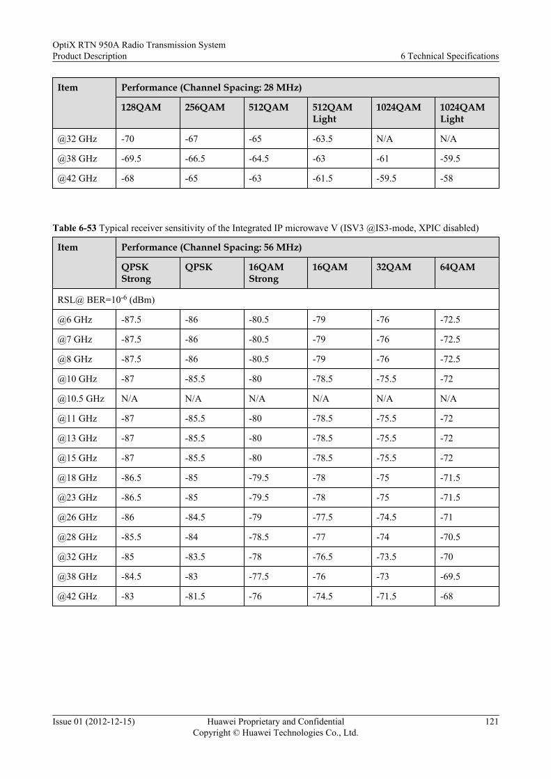
Item Performance (Channel Spacing: 28 MHz)
128QAM 256QAM 512QAM 512QAMLight
1024QAM 1024QAMLight
@32 GHz -70 -67 -65 -63.5 N/A N/A
@38 GHz -69.5 -66.5 -64.5 -63 -61 -59.5
@42 GHz -68 -65 -63 -61.5 -59.5 -58
Table 6-53 Typical receiver sensitivity of the Integrated IP microwave V (ISV3 @IS3-mode, XPIC disabled)
Item Performance (Channel Spacing: 56 MHz)
QPSKStrong
QPSK 16QAMStrong
16QAM 32QAM 64QAM
RSL@ BER=10-6 (dBm)
@6 GHz -87.5 -86 -80.5 -79 -76 -72.5
@7 GHz -87.5 -86 -80.5 -79 -76 -72.5
@8 GHz -87.5 -86 -80.5 -79 -76 -72.5
@10 GHz -87 -85.5 -80 -78.5 -75.5 -72
@10.5 GHz N/A N/A N/A N/A N/A N/A
@11 GHz -87 -85.5 -80 -78.5 -75.5 -72
@13 GHz -87 -85.5 -80 -78.5 -75.5 -72
@15 GHz -87 -85.5 -80 -78.5 -75.5 -72
@18 GHz -86.5 -85 -79.5 -78 -75 -71.5
@23 GHz -86.5 -85 -79.5 -78 -75 -71.5
@26 GHz -86 -84.5 -79 -77.5 -74.5 -71
@28 GHz -85.5 -84 -78.5 -77 -74 -70.5
@32 GHz -85 -83.5 -78 -76.5 -73.5 -70
@38 GHz -84.5 -83 -77.5 -76 -73 -69.5
@42 GHz -83 -81.5 -76 -74.5 -71.5 -68
OptiX RTN 950A Radio Transmission SystemProduct Description 6 Technical Specifications
Issue 01 (2012-12-15) Huawei Proprietary and ConfidentialCopyright © Huawei Technologies Co., Ltd.
121

Table 6-54 Typical receiver sensitivity of the Integrated IP microwave VI (ISV3 @IS3-mode, XPIC disabled)
Item Performance (Channel Spacing: 56 MHz)
128QAM 256QAM 512QAM 512QAMLight
1024QAM 1024QAMLight
RSL@ BER=10-6 (dBm)
@6 GHz -69.5 -66.5 -64.5 -63 -61 N/A
@7 GHz -69.5 -66.5 N/A N/A N/A N/A
@8 GHz -69.5 -66.5 N/A N/A N/A N/A
@10 GHz -69 -66 N/A N/A N/A N/A
@10.5 GHz N/A N/A N/A N/A N/A N/A
@11 GHz -69 -66 -64 -62.5 -60.5 -59
@13 GHz -69 -66 -64 -62.5 -60.5 -59
@15 GHz -69 -66 -64 -62.5 -60.5 -59
@18 GHz -68.5 -65.5 -63.5 -62 -60 -58.5
@23 GHz -68.5 -65.5 -63.5 -62 -60 -58.5
@26 GHz -68 -65 -63 -61.5 -59.5 -58
@28 GHz -67.5 -64.5 -62.5 -61 -59 N/A
@32 GHz -67 -64 -62 -60.5 -58.5 N/A
@38 GHz -66.5 -63.5 -61.5 -60 -58 -56.5
@42 GHz -65 -62 -60 -58.5 -56.5 -55
Table 6-55 Typical receiver sensitivity of the Integrated IP microwave VII (ISV3 @IS3-mode, XPIC disabled)
Item Performance (Channel Spacing: 40 MHz)
QPSKStrong
QPSK 16QAMStrong
16QAM 32QAM 64QAM 128QAM
256QAM
RSL@ BER=10-6 (dBm)
@6 GHz -89 -87.5 -82 -80.5 -77.5 -74 -71 -68
@7 GHz -89 -87.5 -82 -80.5 -77.5 -74 -71 -68
@8 GHz -89 -87.5 -82 -80.5 -77.5 -74 -71 -68
@10 GHz -88.5 -87 -81.5 -80 -77 -73.5 -70.5 -67.5
@10.5GHz
N/A N/A N/A N/A N/A N/A N/A N/A
OptiX RTN 950A Radio Transmission SystemProduct Description 6 Technical Specifications
Issue 01 (2012-12-15) Huawei Proprietary and ConfidentialCopyright © Huawei Technologies Co., Ltd.
122

Item Performance (Channel Spacing: 40 MHz)
QPSKStrong
QPSK 16QAMStrong
16QAM 32QAM 64QAM 128QAM
256QAM
@11 GHz -88.5 -87 -81.5 -80 -77 -73.5 -70.5 -67.5
@13 GHz -88.5 -87 -81.5 -80 -77 -73.5 -70.5 -67.5
@15 GHz -88.5 -87 -81.5 -80 -77 -73.5 -70.5 -67.5
@18 GHz -88 -86.5 -81 -79.5 -76.5 -73 -70 -67
@23 GHz -88 -86.5 -81 -79.5 -76.5 -73 -70 -67
@26 GHz -87.5 -86 -80.5 -79 -76 -72.5 -69.5 -66.5
@28 GHz -87 -85.5 -80 -78.5 -75.5 -72 -69 -66
@32 GHz -86.5 -85 -79.5 -78 -75 -71.5 -68.5 -65.5
@38 GHz -86 -84.5 -79 -77.5 -74.5 -71 -68 -65
@42 GHz -84.5 -83 -77.5 -76 -73 -69.5 -66.5 -63.5
Table 6-56 Typical receiver sensitivity of the Integrated IP microwave I (ISV3 @IS3-mode, XPIC enabled)
Item Performance (Channel Spacing: 7 MHz)
QPSKStrong
QPSK 16QAMStrong
16QAM 32QAM 64QAM 128QAM
RSL@ BER=10-6 (dBm)
@6 GHz -96 -94 -89.5 -87.5 -84.5 -81.5 -78.5
@7 GHz -96 -94 -89.5 -87.5 -84.5 -81.5 -78.5
@8 GHz -96 -94 -89.5 -87.5 -84.5 -81.5 -78.5
@10 GHz -95.5 -93.5 -89 -87 -84 -81 -78
@10.5 GHz -93.5 -91.5 -87 -85 -82 -79 -76
@11 GHz -95.5 -93.5 -89 -87 -84 -81 -78
@13 GHz -95.5 -93.5 -89 -87 -84 -81 -78
@15 GHz -95.5 -93.5 -89 -87 -84 -81 -78
@18 GHz -95 -93 -88.5 -86.5 -83.5 -80.5 -77.5
@23 GHz -95 -93 -88.5 -86.5 -83.5 -80.5 -77.5
@26 GHz -94.5 -92.5 -88 -86 -83 -80 -77
@28 GHz -94 -92 -87.5 -85.5 -82.5 -79.5 -76.5
OptiX RTN 950A Radio Transmission SystemProduct Description 6 Technical Specifications
Issue 01 (2012-12-15) Huawei Proprietary and ConfidentialCopyright © Huawei Technologies Co., Ltd.
123

Item Performance (Channel Spacing: 7 MHz)
QPSKStrong
QPSK 16QAMStrong
16QAM 32QAM 64QAM 128QAM
@32 GHz -93.5 -91.5 -87 -85 -82 -79 -76
@38 GHz -93 -91 -86.5 -84.5 -81.5 -78.5 -75.5
@42 GHz -91.5 -89.5 -85 -83 -80 -77 -74
Table 6-57 Typical receiver sensitivity of the Integrated IP microwave II (ISV3 @IS3-mode, XPIC enabled)
Item Performance (Channel Spacing: 14 MHz)
QPSKStrong
QPSK 16QAMStrong
16QAM 32QAM 64QAM 128QAM
256QAM
RSL@ BER=10-6 (dBm)
@6 GHz -94 -92 -86.5 -84.5 -81.5 -78.5 -75.5 -72.5
@7 GHz -94 -92 -86.5 -84.5 -81.5 -78.5 -75.5 -72.5
@8 GHz -94 -92 -86.5 -84.5 -81.5 -78.5 -75.5 -72.5
@10 GHz -93.5 -91.5 -86 -84 -81 -78 -75 -72
@10.5GHz
-91.5 -89.5 -84 -82 -79 -76 -73 -70
@11 GHz -93.5 -91.5 -86 -84 -81 -78 -75 -72
@13 GHz -93.5 -91.5 -86 -84 -81 -78 -75 -72
@15 GHz -93.5 -91.5 -86 -84 -81 -78 -75 -72
@18 GHz -93 -91 -85.5 -83.5 -80.5 -77.5 -74.5 -71.5
@23 GHz -93 -91 -85.5 -83.5 -80.5 -77.5 -74.5 -71.5
@26 GHz -92.5 -90.5 -85 -83 -80 -77 -74 -71
@28 GHz -92 -90 -84.5 -82.5 -79.5 -76.5 -73.5 -70.5
@32 GHz -91.5 -89.5 -84 -82 -79 -76 -73 -70
@38 GHz -91 -89 -83.5 -81.5 -78.5 -75.5 -72.5 -69.5
@42 GHz -89.5 -87.5 -82 -80 -77 -74 -71 -68
OptiX RTN 950A Radio Transmission SystemProduct Description 6 Technical Specifications
Issue 01 (2012-12-15) Huawei Proprietary and ConfidentialCopyright © Huawei Technologies Co., Ltd.
124

Table 6-58 Typical receiver sensitivity of the Integrated IP microwave III (ISV3 @IS3-mode, XPIC enabled)
Item Performance (Channel Spacing: 28 MHz)
QPSKStrong
QPSK 16QAMStrong
16QAM 32QAM 64QAM
RSL@ BER=10-6 (dBm)
@6 GHz -90.5 -89 -83.5 -82 -79 -75.5
@7 GHz -90.5 -89 -83.5 -82 -79 -75.5
@8 GHz -90.5 -89 -83.5 -82 -79 -75.5
@10 GHz -90 -88.5 -83 -81.5 -78.5 -75
@10.5 GHz -88 -86.5 -81 -79.5 -76.5 -73
@11 GHz -90 -88.5 -83 -81.5 -78.5 -75
@13 GHz -90 -88.5 -83 -81.5 -78.5 -75
@15 GHz -90 -88.5 -83 -81.5 -78.5 -75
@18 GHz -89.5 -88 -82.5 -81 -78 -74.5
@23 GHz -89.5 -88 -82.5 -81 -78 -74.5
@26 GHz -89 -87.5 -82 -80.5 -77.5 -74
@28 GHz -88.5 -87 -81.5 -80 -77 -73.5
@32 GHz -88 -86.5 -81 -79.5 -76.5 -73
@38 GHz -87.5 -86 -80.5 -79 -76 -72.5
@42 GHz -86 -84.5 -79 -77.5 -74.5 -71
Table 6-59 Typical receiver sensitivity of the Integrated IP microwave IV (ISV3 @IS3-mode, XPIC enabled)
Item Performance (Channel Spacing: 28 MHz)
128QAM 256QAM 512QAM 512QAM Light
RSL@ BER=10-6 (dBm)
@6 GHz -72.5 -69.5 N/A N/A
@7 GHz -72.5 -69.5 N/A N/A
@8 GHz -72.5 -69.5 N/A N/A
@10 GHz -72 -69 N/A N/A
@10.5 GHz -70 -67 N/A N/A
@11 GHz -72 -69 -67 -65.5
OptiX RTN 950A Radio Transmission SystemProduct Description 6 Technical Specifications
Issue 01 (2012-12-15) Huawei Proprietary and ConfidentialCopyright © Huawei Technologies Co., Ltd.
125

Item Performance (Channel Spacing: 28 MHz)
128QAM 256QAM 512QAM 512QAM Light
@13 GHz -72 -69 -67 -65.5
@15 GHz -72 -69 -67 -65.5
@18 GHz -71.5 -68.5 -66.5 -65
@23 GHz -71.5 -68.5 -66.5 -65
@26 GHz -71 -68 -66 -64.5
@28 GHz -70.5 -67.5 N/A N/A
@32 GHz -70 -67 N/A N/A
@38 GHz -69.5 -66.5 -64.5 N/A
@42 GHz -68 -65 -63 N/A
Table 6-60 Typical receiver sensitivity of the Integrated IP microwave V (ISV3 @IS3-mode, XPIC enabled)
Item Performance (Channel Spacing: 56 MHz)
QPSKStrong
QPSK 16QAMStrong
16QAM 32QAM 64QAM
RSL@ BER=10-6 (dBm)
@6 GHz -87.5 -86 -80.5 -79 -76 -72.5
@7 GHz -87.5 -86 -80.5 -79 -76 -72.5
@8 GHz -87.5 -86 -80.5 -79 -76 -72.5
@10 GHz -87 -85.5 -80 -78.5 -75.5 -72
@10.5 GHz N/A N/A N/A N/A N/A N/A
@11 GHz -87 -85.5 -80 -78.5 -75.5 -72
@13 GHz -87 -85.5 -80 -78.5 -75.5 -72
@15 GHz -87 -85.5 -80 -78.5 -75.5 -72
@18 GHz -86.5 -85 -79.5 -78 -75 -71.5
@23 GHz -86.5 -85 -79.5 -78 -75 -71.5
@26 GHz -86 -84.5 -79 -77.5 -74.5 -71
@28 GHz -85.5 -84 -78.5 -77 -74 -70.5
@32 GHz -85 -83.5 -78 -76.5 -73.5 -70
@38 GHz -84.5 -83 -77.5 -76 -73 -69.5
OptiX RTN 950A Radio Transmission SystemProduct Description 6 Technical Specifications
Issue 01 (2012-12-15) Huawei Proprietary and ConfidentialCopyright © Huawei Technologies Co., Ltd.
126

Item Performance (Channel Spacing: 56 MHz)
QPSKStrong
QPSK 16QAMStrong
16QAM 32QAM 64QAM
@42 GHz -83 -81.5 -76 -74.5 -71.5 -68
Table 6-61 Typical receiver sensitivity of the Integrated IP microwave VI (ISV3 @IS3-mode, XPIC enabled)
Item Performance (Channel Spacing: 56 MHz)
128QAM 256QAM 512QAM 512QAMLight
1024QAM 1024QAMLight
RSL@ BER=10-6 (dBm)
@6 GHz -69.5 -66.5 -64.5 N/A N/A N/A
@7 GHz -69.5 -66.5 N/A N/A N/A N/A
@8 GHz -69.5 -66.5 N/A N/A N/A N/A
@10 GHz -69 -66 N/A N/A N/A N/A
@10.5 GHz N/A N/A N/A N/A N/A N/A
@11 GHz -69 -66 -64 -62.5 -60.5 -59
@13 GHz -69 -66 -64 -62.5 -60.5 -59
@15 GHz -69 -66 -64 -62.5 -60.5 -59
@18 GHz -68.5 -65.5 -63.5 -62 -60 -58.5
@23 GHz -68.5 -65.5 -63.5 -62 -60 -58.5
@26 GHz -68 -65 -63 -61.5 -59.5 -58
@28 GHz -67.5 -64.5 -62.5 N/A N/A N/A
@32 GHz -67 -64 -62 N/A N/A N/A
@38 GHz -66.5 -63.5 -61.5 -60 N/A N/A
@42 GHz -65 -62 -60 -58.5 N/A N/A
Table 6-62 Typical receiver sensitivity of the Integrated IP microwave VII (ISV3 @IS3-mode, XPIC enabled)
Item Performance (Channel Spacing: 40 MHz)
QPSKStrong
QPSK 16QAMStrong
16QAM 32QAM 64QAM 128QAM
256QAM
RSL@ BER=10-6 (dBm)
OptiX RTN 950A Radio Transmission SystemProduct Description 6 Technical Specifications
Issue 01 (2012-12-15) Huawei Proprietary and ConfidentialCopyright © Huawei Technologies Co., Ltd.
127

Item Performance (Channel Spacing: 40 MHz)
QPSKStrong
QPSK 16QAMStrong
16QAM 32QAM 64QAM 128QAM
256QAM
@6 GHz -89 -87.5 -82 -80.5 -77.5 -74 -71 -68
@7 GHz -89 -87.5 -82 -80.5 -77.5 -74 -71 -68
@8 GHz -89 -87.5 -82 -80.5 -77.5 -74 -71 -68
@10 GHz -88.5 -87 -81.5 -80 -77 -73.5 -70.5 -67.5
@10.5GHz
N/A N/A N/A N/A N/A N/A N/A N/A
@11 GHz -88.5 -87 -81.5 -80 -77 -73.5 -70.5 -67.5
@13 GHz -88.5 -87 -81.5 -80 -77 -73.5 -70.5 -67.5
@15 GHz -88.5 -87 -81.5 -80 -77 -73.5 -70.5 -67.5
@18 GHz -88 -86.5 -81 -79.5 -76.5 -73 -70 -67
@23 GHz -88 -86.5 -81 -79.5 -76.5 -73 -70 -67
@26 GHz -87.5 -86 -80.5 -79 -76 -72.5 -69.5 -66.5
@28 GHz -87 -85.5 -80 -78.5 -75.5 -72 -69 -66
@32 GHz -86.5 -85 -79.5 -78 -75 -71.5 -68.5 -65.5
@38 GHz -86 -84.5 -79 -77.5 -74.5 -71 -68 -65
@42 GHz -84.5 -83 -77.5 -76 -73 -69.5 -66.5 -63.5
6.1.4 Distortion SensitivityThe distortion sensitivity reflects the anti-multipath fading capability of the OptiX RTN 950A.
The notch depth of the OptiX RTN 950A meets the requirements described in ETSI EN302217-2-1. Table 6-63 describes the anti-multipath fading capability of the OptiX RTN950A in STM-1/128QAM microwave working modes.
Table 6-63 Anti-multipath fading capability
Item Performance
STM-1/128QAM W-curve See Figure 6-1
STM-1/128QAM dispersion fading margin 51 dB
OptiX RTN 950A Radio Transmission SystemProduct Description 6 Technical Specifications
Issue 01 (2012-12-15) Huawei Proprietary and ConfidentialCopyright © Huawei Technologies Co., Ltd.
128

Figure 6-1 W-curve
6.1.5 Transceiver PerformanceThe performance of the transceiver includes the nominal maximum/minimum transmit power,nominal maximum receive power, and frequency stability.
Transceiver Performance (High Power ODU)
Table 6-64 Transceiver performance (XMC-2 ODU)
Item Performance
QPSK 16QAM 32QAM 64QAM 128QAM
256QAM
512QAM
1024QAM
Nominal maximum transmit power (dBm)NOTEl The value behind the slash is the maximum transmit power that is supported when the ODU works with an IF board in IS3
mode.
l When the working frequency is 7 GHz or 8 GHz and the channel spacing is 40/50/56 MHz, the maximum transmit power ineach modulation reduces by 3 dB.
@6 GHz 30 28 26.5 25 25 23 21 19
@7 GHz 26.5 25.5 25.5 25 25 23 - -
@8 GHz 26.5 25.5 25.5 25 25 23 - -
@11GHz 26 24/25 24/25 22/24 22/24 20/22 22 20
@13 GHz 25 22/24 22/24 20.5/23 20.5/23 17.5/21 20 18
@15 GHz 25 22/24 22/24 20.5/23 20.5/23 18.5/21 21 19
@18 GHz 24 21/23 21/23 19.5/22 19.5/22 16.5/20 19 17
OptiX RTN 950A Radio Transmission SystemProduct Description 6 Technical Specifications
Issue 01 (2012-12-15) Huawei Proprietary and ConfidentialCopyright © Huawei Technologies Co., Ltd.
129

Item Performance
QPSK 16QAM 32QAM 64QAM 128QAM
256QAM
512QAM
1024QAM
@23 GHz 24 21/23 21/23 19.5/22 19.5/22 17.5/19.5 19.5 18
@26 GHz 22 20/21 20/21 18/20 18/20 16/17 17 15
@28 GHz 25 22 21.5 19 19 17 15 13
@32 GHz 23 21 19.5 17 17 15 13 11
@38 GHz 20 17/18 17/18 16/17 16/17 14/16 15 13
@42 GHz 16 12/14 12/14 11/13 11/13 9/11 10 8
Nominal minimum transmit power (dBm)
@6 GHz 0
@7 GHz 6.5 - -
@8 GHz 6.5 - -
@11GHz 0
@13 GHz 5
@15 GHz 5
@18 GHz 4
@23 GHz 4
@26 GHz 0
@28 GHz -3
@32 GHz -3
@38 GHz 0
@42 GHz -5
Nominalmaximumreceivepower(dBm)
-20 -20 (6GHz to 38GHz)-23 (42GHz)
-20 (6GHz to 38GHz)-25 (42GHz)
-25
Frequency stability(ppm)
±5
OptiX RTN 950A Radio Transmission SystemProduct Description 6 Technical Specifications
Issue 01 (2012-12-15) Huawei Proprietary and ConfidentialCopyright © Huawei Technologies Co., Ltd.
130

Table 6-65 Transceiver performance (HP ODU)
Item Performance
QPSK 16QAM/32QAM
64QAM/128QAM
256QAM
Nominal maximum transmit power (dBm)
@6 GHz 30 26 24 22
@7 GHz 30 28 25 23
@8 GHz 30 28 25 23
@10 GHz 26.5 22.5 20.5 18.5
@10.5 GHz 24 20.5 18 16
@11 GHz 28 26 22 20
@13 GHz 26 24 20 18
@15 GHz 26 24 20 18
@18 GHz 25.5 23 19 17
@23 GHz 25 23 19 17
@26 GHz 25 22 19 17
@28GHz 25 22 17 15
@32 GHz 23 21 17 15
@38 GHz 23 20 17 15
Nominal minimum transmit power (dBm)
@6 GHz 9
@7 GHz 9
@8 GHz 9
@10 GHz 2
@10.5 GHz 0
@11 GHz 6
@13 GHz 3
@15 GHz 3
@18 GHz 2
@23 GHz 2
@26 GHz 2
@28GHz 2
OptiX RTN 950A Radio Transmission SystemProduct Description 6 Technical Specifications
Issue 01 (2012-12-15) Huawei Proprietary and ConfidentialCopyright © Huawei Technologies Co., Ltd.
131

Item Performance
QPSK 16QAM/32QAM
64QAM/128QAM
256QAM
@32 GHz 1
@38 GHz 1
Nominalmaximumreceive power(dBm)
-20 -25
Frequencystability (ppm)
±5
Table 6-66 Transceiver Performance (HPA ODU)
Item Performance
QPSK 16QAM/32QAM
64QAM/128QAM
256QAM
Nominal maximum transmit power (dBm)
@6 GHz 30 28 (16QAM)26.5 (32QAM)
25 23
@7 GHz 30 28 25 23
@8 GHz 30 28 25 23
@11 GHz 28 26 22 20
@13 GHz 26 24 20 18
@15 GHz 26 24 20 18
@18 GHz 25.5 23 19 17
@23 GHz 25 23 19 17
Nominal minimum transmit power (dBm)
@6 GHz 9
@7 GHz 9
@8 GHz 9
@11 GHz 6
@13 GHz 3
@15 GHz 3
OptiX RTN 950A Radio Transmission SystemProduct Description 6 Technical Specifications
Issue 01 (2012-12-15) Huawei Proprietary and ConfidentialCopyright © Huawei Technologies Co., Ltd.
132

Item Performance
QPSK 16QAM/32QAM
64QAM/128QAM
256QAM
@18 GHz 2
@23 GHz 2
Nominalmaximumreceive power(dBm)
-20 -25
Frequencystability (ppm)
±5
Transceiver Performance (Standard Power ODU)
Table 6-67 Transceiver Performance (SP ODU)
Item Performance
QPSK 16QAM/32QAM
64QAM/128QAM
256QAM
Nominal maximum transmit power (dBm)
@7 GHz 27 22.5 18.5 16.5
@8 GHz 27 22.5 18.5 16.5
@11 GHz 26 21.5 17.5 15.5
@13 GHz 26 21.5 17.5 15.5
@15 GHz 26 21.5 17.5 15.5
@18 GHz 25.5 21.5 17.5 15.5
@23 GHz 24 20.5 16.5 14.5
@26 GHz 23.5 19.5 15.5 13.5
@38 GHz 22 17.5 13.5 11.5
Nominalminimumtransmit power(dBm)
-6
Nominalmaximumreceive power(dBm)
-20 -25
OptiX RTN 950A Radio Transmission SystemProduct Description 6 Technical Specifications
Issue 01 (2012-12-15) Huawei Proprietary and ConfidentialCopyright © Huawei Technologies Co., Ltd.
133

Item Performance
QPSK 16QAM/32QAM
64QAM/128QAM
256QAM
Frequencystability (ppm)
±5
Table 6-68 Transceiver performance (SPA ODU)
Item Performance
QPSK 16QAM/32QAM
64QAM/128QAM
256QAM
Nominal maximum transmit power (dBm)
@6 GHz 26.5 24 23 21
@7 GHz 25.5 21.5 20 18
@8 GHz 25.5 21.5 20 18
@11 GHz 24.5 20.5 18 16
@13 GHz 24.5 20 18 16
@15 GHz 24.5 20 18 16
@18 GHz 22.5 19 17 15
@23 GHz 22.5 19 16 14
Nominalminimumtransmit power(dBm)
0
Nominalmaximumreceive power(dBm)
-20 -25
Frequencystability (ppm)
±5
OptiX RTN 950A Radio Transmission SystemProduct Description 6 Technical Specifications
Issue 01 (2012-12-15) Huawei Proprietary and ConfidentialCopyright © Huawei Technologies Co., Ltd.
134

Transceiver Performance (Low Capacity ODU)
Table 6-69 Transceiver performance (XMC-1 ODU)
Item Performance
QPSK 16QAM
Nominal maximum transmit power (dBm)
@7 GHz 26.5 21
@8 GHz 26.5 21
@11GHz 25 19
@13 GHz 25 19
@15 GHz 23.5 17.5
@18 GHz 23 17
@23 GHz 23 17
Nominal minimum transmit power (dBm)
@7 GHz 6.5
@8 GHz 6.5
@11GHz 0
@13 GHz 5
@15 GHz 5
@18 GHz 4
@23 GHz 4
Nominal maximum receivepower (dBm)
-20
Frequency stability (ppm) ±5
6.1.6 IF PerformanceThe IF performance includes the performance of the IF signal and the performance of the ODUO&M signal.
Table 6-70 IF performance
Item Performance
IF signal Transmit frequency of the IF board (MHz) 350
OptiX RTN 950A Radio Transmission SystemProduct Description 6 Technical Specifications
Issue 01 (2012-12-15) Huawei Proprietary and ConfidentialCopyright © Huawei Technologies Co., Ltd.
135

Item Performance
Receive frequency of the IF board (MHz) 140
ODU O&M signal Modulation scheme ASK
Transmit frequency of the IF board (MHz) 5.5
Receive frequency of the IF board (MHz) 10
Interface impedance (ohm) 50
6.1.7 Baseband Signal Processing Performance of the ModemThe baseband signal processing performance of the modem indicates the FEC coding schemeand the performance of the baseband time domain adaptive equalizer.
Table 6-71 Baseband signal processing performance of the modem
Item Performance
Encoding mode Low-density parity check code (LDPC) encoding.
Adaptive time-domain equalizer forbaseband signals
Supported.
6.2 Predicted Equipment ReliabilityPredicted equipment reliability includes predicted component reliability and predicted linkreliability. Equipment reliability is measured by mean time between failures (MTBF), andpredicated equipment reliability complies with the Telcordia SR-332 standard.
6.2.1 Predicted Component ReliabilityThe component reliability reflects the reliability of a single component.
provides the predicted component reliability for the Integrated IP radio equipment with typicalconfiguration.
Table 6-72 Predicted component reliability
Item Performance
IDU ODU
1+0 Non-ProtectionConfiguration
1+1 ProtectionConfiguration
MTBF (hour) 34.15x10⁴ 47.80x10⁴ ≥48.18x10⁴
OptiX RTN 950A Radio Transmission SystemProduct Description 6 Technical Specifications
Issue 01 (2012-12-15) Huawei Proprietary and ConfidentialCopyright © Huawei Technologies Co., Ltd.
136
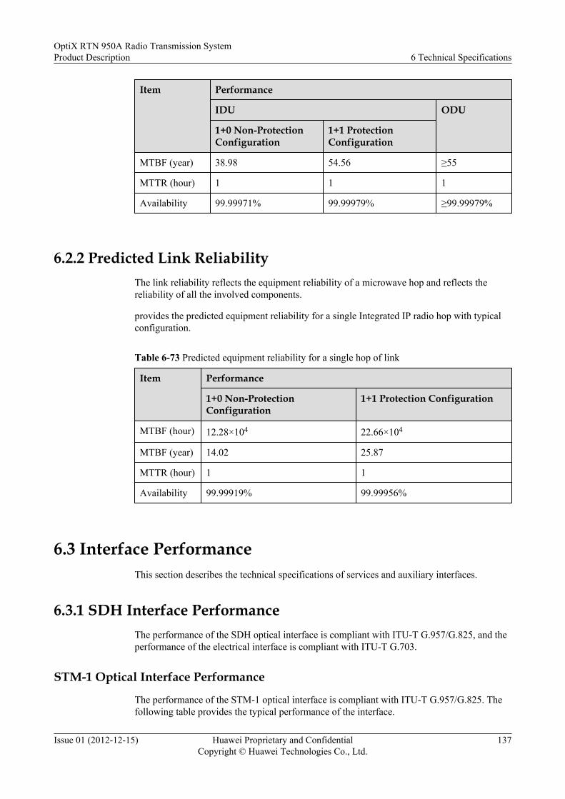
Item Performance
IDU ODU
1+0 Non-ProtectionConfiguration
1+1 ProtectionConfiguration
MTBF (year) 38.98 54.56 ≥55
MTTR (hour) 1 1 1
Availability 99.99971% 99.99979% ≥99.99979%
6.2.2 Predicted Link ReliabilityThe link reliability reflects the equipment reliability of a microwave hop and reflects thereliability of all the involved components.
provides the predicted equipment reliability for a single Integrated IP radio hop with typicalconfiguration.
Table 6-73 Predicted equipment reliability for a single hop of link
Item Performance
1+0 Non-ProtectionConfiguration
1+1 Protection Configuration
MTBF (hour) 12.28×10⁴ 22.66×10⁴
MTBF (year) 14.02 25.87
MTTR (hour) 1 1
Availability 99.99919% 99.99956%
6.3 Interface PerformanceThis section describes the technical specifications of services and auxiliary interfaces.
6.3.1 SDH Interface PerformanceThe performance of the SDH optical interface is compliant with ITU-T G.957/G.825, and theperformance of the electrical interface is compliant with ITU-T G.703.
STM-1 Optical Interface Performance
The performance of the STM-1 optical interface is compliant with ITU-T G.957/G.825. Thefollowing table provides the typical performance of the interface.
OptiX RTN 950A Radio Transmission SystemProduct Description 6 Technical Specifications
Issue 01 (2012-12-15) Huawei Proprietary and ConfidentialCopyright © Huawei Technologies Co., Ltd.
137

Table 6-74 STM-1 optical interface performance (two-fiber bidirectional)
Item Performance
Nominal bit rate (kbit/s) 155520
Classification code Ie-1 S-1.1 L-1.1 L-1.2
Fiber type Multi-modefiber
Single-modefiber
Single-modefiber
Single-modefiber
Transmission distance(km)
2 15 40 80
Operating wavelength(nm)
1270 to 1380 1261 to 1360 1263 to 1360 1480 to 1580
Mean launched power(dBm)
-19 to -14 -15 to -8 -5 to 0 -5 to 0
Receiver minimumsensitivity (dBm)
-30 -28 -34 -34
Minimum overload (dBm) -14 -8 -10 -10
Minimum extinction ratio(dB)
10 8.2 10 10
NOTE
The OptiX RTN 950A uses SFP optical modules for providing optical interfaces. You can use different typesof SFP optical modules to provide optical interfaces with different classification codes and transmissiondistances.
Table 6-75 STM-1 optical interface performance (single-fiber bidirectional)
Item Performance
Nominal bit rate (kbit/s) 155520
Classification code S-1.1-BX-D S-1.1-BX-U L-1.1-BX-D L-1.1-BX-U
Fiber type Single-modefiber
Single-modefiber
Single-modefiber
Single-modefiber
Transmission distance(km)
15 15 40 40
Nominal wavelength (nm) Tx: 1550Rx: 1310
Tx: 1310Rx: 1550
Tx: 1550Rx: 1310
Tx: 1310Rx: 1550
Operating wavelength(nm)
Tx: 1480 to1580Rx: 1260 to1360
Tx: 1260 to1360Rx: 1480 to1580
Tx: 1480 to1580Rx: 1260 to1360
Tx: 1260 to1360Rx: 1480 to1580
OptiX RTN 950A Radio Transmission SystemProduct Description 6 Technical Specifications
Issue 01 (2012-12-15) Huawei Proprietary and ConfidentialCopyright © Huawei Technologies Co., Ltd.
138

Item Performance
Mean launched power(dBm)
-15 to -8 -15 to -8 -5 to 0 -5 to 0
Receiver minimumsensitivity (dBm)
-32 -32 -32 -32
Minimum overload (dBm) -8 -8 -10 -10
Minimum extinction ratio(dB)
8.5 8.5 10 10
NOTE
The OptiX RTN 950A uses SFP optical modules for providing optical interfaces. You can use different typesof SFP optical modules to provide optical interfaces with different classification codes and transmissiondistances.
STM-1 Electrical Interface PerformanceThe performance of the STM-1 electrical interface is compliant with ITU-T G.703. Thefollowing table provides the typical performance of the interface.
Table 6-76 STM-1 electrical interface performance
Item Performance
Nominal bit rate (kbit/s) 155520
Code type CMI
Wire pair in eachtransmission direction
One coaxial wire pair
Impedance (ohm) 75
NOTEThe OptiX RTN 950A uses SFP electrical modules to provide electrical interfaces.
6.3.2 E1 Interface PerformanceThe performance of the E1 interface is compliant with ITU-T G.703/G.823.
E1 Interface Performance
Table 6-77 E1 interface performance
Item Performance
Nominal bit rate (kbit/s) 2048
OptiX RTN 950A Radio Transmission SystemProduct Description 6 Technical Specifications
Issue 01 (2012-12-15) Huawei Proprietary and ConfidentialCopyright © Huawei Technologies Co., Ltd.
139

Item Performance
Code pattern HDB3
Impedance (ohm) 75 120
Wire pair in eachtransmission direction
One coaxial wire pair One symmetrical wire pair
6.3.3 Ethernet Interface PerformanceEthernet interface performance complies with IEEE 802.3.
GE Optical Interface Performance
The characteristics of GE optical interfaces comply with IEEE 802.3. Table 6-78 to Table6-80 provide GE optical interface performance.
Table 6-78 GE optical interface performance(two-fiber bidirectional, short-distancetransmission)
Item Performance
Classification code 1000BASE-SX (0.5 km) 1000BASE-LX (10 km)
Nominal wavelength (nm) 850 1310
Nominal bit rate (Mbit/s) 1000
Fiber type Multi-mode Single-mode
Transmission distance (km) 0.5 10
Operating wavelength (nm) 770 to 860 1270 to 1355
Average optical outputpower (dBm)
-9 to -3 -9 to -3
Receiver sensitivity (dBm) -17 -20
Overload (dBm) 0 -3
Extinction ratio (dB) 9.5 9.5
Table 6-79 GE optical interface performance (two-fiber bidirectional, long-haul transmission)
Item Performance
Classification code 1000BASE-VX (40km)
1000BASE-VX (40km)
1000BASE-ZX (80km)
Nominal wavelength (nm) 1310 1550 1550
OptiX RTN 950A Radio Transmission SystemProduct Description 6 Technical Specifications
Issue 01 (2012-12-15) Huawei Proprietary and ConfidentialCopyright © Huawei Technologies Co., Ltd.
140

Item Performance
Classification code 1000BASE-VX (40km)
1000BASE-VX (40km)
1000BASE-ZX (80km)
Nominal bit rate (Mbit/s) 1000 1000 1000
Fiber type Single-mode Single-mode Single-mode
Transmission distance (km) 40 40 80
Operating wavelength (nm) 1270 to 1350 1480 to 1580 1500 to 1580
Average optical output power(dBm)
-5 to 0 -5 to 0 -2 to +5
Receiver sensitivity (dBm) -23 -22 -22
Overload (dBm) -3 -3 -3
Extinction ratio (dB) 9 9 9
Table 6-80 GE optical interface performance (single-fiber bidirectional)
Item Performance
1000BASE-BX-D (10 km)
1000BASE-BX-U (10km)
1000BASE-BX-D (40 km)
1000BASE-BX-U (40km)
Nominal wavelength (nm) Tx: 1490Rx: 1310
Tx: 1310Rx: 1490
Tx: 1490Rx: 1310
Tx: 1310Rx: 1490
Nominal bit rate (Mbit/s) 1000 1000 1000 1000
Fiber type Single-mode Single-mode Single-mode Single-mode
Transmission distance (km) 10 10 40 40
Operating wavelength (nm) Tx: 1480 to 1500Rx: 1260 to1360
Tx: 1260 to1360Rx: 1480 to1500
Tx: 1260 to 1360Rx: 1480 to1500
Tx: 1480 to 1500Rx: 1260 to1360
Average optical output power(dBm)
-9 to -3 -9 to -3 -3 to +3 -3 to +3
Receiver sensitivity (dBm) -19.5 -19.5 -23 -23
Overload (dBm) -3 -3 -3 -3
Extinction ratio (dB) 6 6 6 6
OptiX RTN 950A Radio Transmission SystemProduct Description 6 Technical Specifications
Issue 01 (2012-12-15) Huawei Proprietary and ConfidentialCopyright © Huawei Technologies Co., Ltd.
141

NOTE
The OptiX RTN 950A uses SFP modules to provide GE optical interfaces. Users can use different types of SFPmodules to provide GE optical interfaces with different classification codes and transmission distances.
GE Electrical Interface PerformanceThe characteristics of GE electrical interfaces comply with IEEE 802.3. The following tableprovides GE electrical interface performance.
Table 6-81 GE electrical interface performance
Item Performance
Nominal bit rate (Mbit/s) 10 (10BASE-T)100 (100BASE-TX)1000 (1000BASE-T)
Code pattern Manchester encoding signal (10BASE-T)MLT-3 encoding signal (100BASE-TX)4D-PAM5 encoding signal (1000BASE-T)
Interface type RJ45
FE Optical Interface PerformanceThe characteristics of FE optical interfaces comply with IEEE 802.3. Table 6-82 to Table6-83 provide FE optical interface performance.
Table 6-82 FE optical interface performance (two-fiber bidirectional)
Item Performance
100BASE-FX(2 km)
100BASE-LX(15 km)
100BASE-VX(40 km)
100BASE-ZX(80 km)
Nominal wavelength (nm) 1310 1310 1310 1550
Nominal bit rate (Mbit/s) 100 100 100 100
Fiber type Multi-mode Single-mode Single-mode Single-mode
Transmission distance (km) 2 15 40 80
Operating wavelength (nm) 1270 to 1380 1261 to 1360 1263 to 1360 1480 to 1580
Average optical output power(dBm)
-19 to -14 -15 to -8 -5 to 0 -5 to 0
Receiver sensitivity (dBm) -30 -28 -34 -34
Overload (dBm) -14 -8 -10 -10
Extinction ratio (dB) 10 8.2 10 10.5
OptiX RTN 950A Radio Transmission SystemProduct Description 6 Technical Specifications
Issue 01 (2012-12-15) Huawei Proprietary and ConfidentialCopyright © Huawei Technologies Co., Ltd.
142

Table 6-83 FE optical interface performance (single-fiber bidirectional)
Item Performance
Classificationcode
100BASE-BX-D (15 km)
100BASE-BX-U (15 km)
100BASE-BX-D (40 km)
100BASE-BX-U (40 km)
Nominalwavelength(nm)
Tx: 1550Rx: 1310
Tx: 1310Rx: 1550
Tx: 1550Rx: 1310
Tx: 1310Rx: 1550
Nominal bit rate(Mbit/s)
100 100 100 100
Fiber type Single-mode Single-mode Single-mode Single-mode
Transmissiondistance (km)
15 15 40 40
Operatingwavelength(nm)
Tx: 1480 to1580Rx: 1260 to1360
Tx: 1260 to1360Rx: 1480 to1580
Tx: 1480 to1580Rx: 1260 to1360
Tx: 1260 to1360Rx: 1480 to1580
Average opticaloutput power(dBm)
-15 to -8 -15 to -8 -5 to 0 -5 to 0
Receiversensitivity(dBm)
-32 -32 -32 -32
Overload (dBm) -8 -8 -10 -10
Extinction ratio(dB)
8.5 8.5 10 10
NOTE
The OptiX RTN 950A uses SFP modules to provide FE optical interfaces. Users can use different types of SFPmodules to provide FE optical interfaces with different classification codes and transmission distances.
FE Electrical Interface PerformanceThe characteristics of FE interfaces comply with IEEE 802.3. The following table provides FEelectrical interface performance.
OptiX RTN 950A Radio Transmission SystemProduct Description 6 Technical Specifications
Issue 01 (2012-12-15) Huawei Proprietary and ConfidentialCopyright © Huawei Technologies Co., Ltd.
143

Table 6-84 FE electrical interface performance
Item Performance
Nominal bit rate (Mbit/s) 10 (10BASE-T)100 (100BASE-TX)
Code pattern Manchester encoding signal (10BASE-T)MLT-3 encoding signal (100BASE-TX)
Interface type RJ45
6.3.4 Auxiliary Interface PerformanceThe auxiliary interface performance includes the performance of the asynchronous datainterface.
Orderwire Interface Performance
Table 6-85 Orderwire interface performance
Item Performance
Transmission path Uses the E1 and E2 bytes in the SDH overhead or the Huawei-defined byte in the overhead of the microwave frame.
Orderwire type Addressing call
Wire pair in eachtransmission direction
One symmetrical wire pair
Impedance (ohm) 600
NOTE
The OptiX RTN equipment also supports the orderwire group call function. For example, when OptiX RTNequipment calls 888, the orderwire group call number, all the OptiX RTN equipment orderwire phones in theorderwire subnet ring until a phone is answered. Then, a point-to-point orderwire phone call is established.
Synchronous Data Interface Performance
Table 6-86 Synchronous data interface performance
Item Performance
Transmission path Uses the F1 byte in the SDH overhead or the Huawei-definedbyte in the overhead of the microwave frame.
Nominal bit rate (kbit/s) 64
Interface type Codirectional
OptiX RTN 950A Radio Transmission SystemProduct Description 6 Technical Specifications
Issue 01 (2012-12-15) Huawei Proprietary and ConfidentialCopyright © Huawei Technologies Co., Ltd.
144

Item Performance
Interface characteristics Meets the ITU-T G.703 standard.
Asynchronous Data Interface
Table 6-87 Asynchronous data interface performance
Item Performance
Transmission path Uses the Huawei-defined byte in the overhead of themicrowave frame.
Nominal bit rate (kbit/s) ≤ 19.2
Interface characteristics Meets the RS-232 standard.
Wayside Service Interface Performance
Table 6-88 Wayside service interface performance
Item Performance
Transmission path Uses the Huawei-defined bytes in the overhead of themicrowave frame.
Nominal bit rate (kbit/s) 2048
Impedance (ohm) 120
Interface characteristics Meets the ITU-T G.703 standard.
6.4 Clock Timing and Synchronization PerformanceThe clock timing performance and synchronization performance of the product meet relevantITU-T recommendations.
Table 6-89 Clock timing and synchronization performance
Item Performance
External synchronizationsource
2048 kbit/s (compliant with ITU-T G.703 §9), or 2048 kHz(compliant with ITU-T G.703 §13)
Frequency accuracy Compliant with ITU-T G.813
Pull-in and pull-out ranges
OptiX RTN 950A Radio Transmission SystemProduct Description 6 Technical Specifications
Issue 01 (2012-12-15) Huawei Proprietary and ConfidentialCopyright © Huawei Technologies Co., Ltd.
145

Item Performance
Noise generation
Noise tolerance
Noise transfer
Transient response andholdover performance
6.5 Integrated System PerformanceIntegrated system performance includes the dimensions, weight, power consumption, powersupply, EMC, surge protection, safety, and environment.
Dimensions
Table 6-90 Dimensions
Component Dimensions
IDU 442 mm (W) x 88 mm (H) x 220 mm (D)
ODU < 280 mm (W) x 280 mm (H) x 92 mm (D)
Weight
Table 6-91 Typical weight
Component Typical Weight
IDU 5.4 kg, (1+0 non-protection)6.2 kg, (1+1 protection)
ODU < 4.6 kg
Power Supply
Table 6-92 Power Supply
Component Performance
IDU l Compliant with ETSI EN300 132-2l Supports two -48 V (-38.4 V to -57.6 V) DC power inputs (mutual
backup)
OptiX RTN 950A Radio Transmission SystemProduct Description 6 Technical Specifications
Issue 01 (2012-12-15) Huawei Proprietary and ConfidentialCopyright © Huawei Technologies Co., Ltd.
146

Component Performance
ODU l Compliant with ETSI EN300 132-2l Supports one -48 V (-38.4 V to -72 V) DC power input that is
provided by the IDU
Electromagnetic Compatibilityl Passes CE authentication.l Compliant with ETSI EN 301 489-1.l Compliant with ETSI EN 301 489-4.l Compliant with CISPR 22.l Compliant with EN 55022.
Lightning Protectionl Compliant with ITU-T K.27.l Compliant with ETSI EN 300 253.
Safetyl Passes CE authentication.l Compliant with ETSI EN 60215.l Compliant with ETSI EN 60950.l Compliant with IEC 60825.
Environment
The IDU is used in a place that has weather protection and where the temperature can becontrolled. The ODU is an outdoor unit.
Table 6-93 Environment performance
Item Component
IDU ODU
Majorreferencestandards
Operation Compliant with ETSI EN300 019-1-3 class 3.2
Compliant with ETSI EN300 019-1-4 class 4.1
Transportation Compliant with ETSI EN 300 019-1-2 class 2.3
Storage Compliant with ETSI EN 300 019-1-1 class 1.2
Airtemperature
Operation Long-term: -5°C to +60°CShort-term: -20°C to +65°C
-35°C to +55°C
Transportationand storage
-40°C to +70°C
OptiX RTN 950A Radio Transmission SystemProduct Description 6 Technical Specifications
Issue 01 (2012-12-15) Huawei Proprietary and ConfidentialCopyright © Huawei Technologies Co., Ltd.
147

Item Component
IDU ODU
Relative humidity 5% to 95% 5% to 100%
Noise < 7.2 bel, compliant withETSI EN 300 753 class 3.2attended
-
Earthquake Compliant with Bellcore GR-63-CORE ZONE 4
Mechanical stress Compliant with ETSI EN 300 019
OptiX RTN 950A Radio Transmission SystemProduct Description 6 Technical Specifications
Issue 01 (2012-12-15) Huawei Proprietary and ConfidentialCopyright © Huawei Technologies Co., Ltd.
148

A Typical Configuration
This topic introduces equipment configuration in typical scenarios.
A.1 Typical RF Configuration ModesThis topic provides an overview of the typical configuration modes of RF links of the OptiXRTN 950A.
OptiX RTN 950A Radio Transmission SystemProduct Description A Typical Configuration
Issue 01 (2012-12-15) Huawei Proprietary and ConfidentialCopyright © Huawei Technologies Co., Ltd.
149

A.1 Typical RF Configuration ModesThis topic provides an overview of the typical configuration modes of RF links of the OptiXRTN 950A.
Figure A-1 shows typical RF configuration modes. In practice, configurations are flexible.
Figure A-1 Typical RF configuration modes
1+1 HSB
f1
1+0 2x(1+0)
1+1 FD
f1f2
1+1 SDf1
f1
XPIC
f1f1
V
H
V
H
V
H
N+1
f2 - working. . . . . .
f1 - working
fn - protection. . .
f3 - working
OptiX RTN 950A Radio Transmission SystemProduct Description A Typical Configuration
Issue 01 (2012-12-15) Huawei Proprietary and ConfidentialCopyright © Huawei Technologies Co., Ltd.
150

B Compliance Standards
B.1 ITU-R StandardsThe OptiX RTN 950A complies with the ITU-R standards designed for microwave equipment.
B.2 ETSI StandardsThe OptiX RTN 950A complies with the ETSI standards designed for microwave equipment.
B.3 IEC StandardsThe OptiX RTN 950A is compliant with the IEC standards related to the waveguide.
B.4 ITU-T StandardsThe OptiX RTN 950A complies with the ITU-T standards designed for SDH/PDH equipment.
B.5 IETF StandardsThe OptiX RTN 950A complies with IETF standards.
B.6 IEEE StandardsThe OptiX RTN 950A complies with the IEEE standards designed for Ethernet networks.
B.7 MEF StandardsThe OptiX RTN 950A complies with MEF standards.
B.8 AF StandardsThe OptiX RTN 950A complies with AF standards.
B.9 Environmental StandardsThe OptiX RTN 950A complies with the environmental standards designed for split-mountmicrowave equipment.
OptiX RTN 950A Radio Transmission SystemProduct Description B Compliance Standards
Issue 01 (2012-12-15) Huawei Proprietary and ConfidentialCopyright © Huawei Technologies Co., Ltd.
151

B.1 ITU-R StandardsThe OptiX RTN 950A complies with the ITU-R standards designed for microwave equipment.
Table B-1 ITU-R standard
Standard Description
ITU-R F.383-8 Radio-frequency channel arrangements for high capacity radio-relaysystems operating in the lower 6 GHz band
ITU-R F.384-10 Radio-frequency channel arrangements for medium and high capacityanalogue or digital radio-relay systems operating in the upper 6 GHzband
ITU-R F.385-9 Radio-frequency channel arrangements for fixed wireless systemsoperating in the 7 GHz band
ITU-R F.386-8 Radio-frequency channel arrangements for medium and high capacityanalogue or digital radio-relay systems operating in the 8 GHz band
ITU-R F.387-10 Radio-frequency channel arrangements for radio-relay systemsoperating in the 11 GHz band
ITU-R F.497-7 Radio-frequency channel arrangements for radio-relay systemsoperating in the 13 GHz frequency band
ITU-R F.595-9 Radio-frequency channel arrangements for fixed wireless systemsoperating in the 18 GHz frequency band
ITU-R F.636-3 Radio-frequency channel arrangements for radio-relay systemsoperating in the 15 GHz band
ITU-R F.637-3 Radio-frequency channel arrangements for radio-relay systemsoperating in the 23 GHz band
ITU-R F.747 Radio-frequency channel arrangements for fixed wireless systemsoperating in the 10 GHz band
ITU-R F.748-4 Radio-frequency channel arrangements for radio-relay systemsoperating in the 25, 26 and 28 GHz bands
ITU-R F.749-2 Radio-frequency arrangements for systems of the fixed serviceoperating in the 38 GHz band
ITU-R F.1191-1-2 Bandwidths and unwanted emissions of digital radio-relay systems
ITU-R F.1520-2 Radio-frequency channel arrangements for systems in the fixedservice operating in the band 31.8-33.4 GHz
ITU-R P.530-12 Propagation data and prediction methods required for the design ofterrestrial line-of-sight systems
ITU-R P.453-9 The radio refractive index: its formula and refractivity data
ITU-R P.525-2 Calculation of free-space attenuation
OptiX RTN 950A Radio Transmission SystemProduct Description B Compliance Standards
Issue 01 (2012-12-15) Huawei Proprietary and ConfidentialCopyright © Huawei Technologies Co., Ltd.
152

Standard Description
ITU-R P.837-5 Characteristics of precipitation for propagation modelling
ITU-R P.838-3 Specific attenuation model for rain for use in prediction methods
ITU-R F.1093Effects of multipath propagation on the design and operation of line-of-sight digital fixed wireless systems
ITU-R F.1101 Characteristics of digital fixed wireless systems below about 17 GHz
ITU-R F.1102 Characteristics of fixed wireless systems operating in frequencybands above about 17 GHz
ITU-R F.1330 Performance limits for bringing into service the parts of internationalplesiochronous digital hierarchy and synchronous digital hierarchypaths and sections implemented by digital fixed wireless systems
ITU-R F.1605 Error performance and availability estimation for synchronous digitalhierarchy terrestrial fixed wireless systems
ITU-R F.1668 Error performance objectives for real digital fixed wireless links usedin 27 500 km hypothetical reference paths and connections
ITU-R F.1703 Availability objectives for real digital fixed wireless links used in 27500 km hypothetical reference paths and connections
ITU-R F.592 Vocabulary of terms for the fixed service
ITU-R F.746 Radio-frequency arrangements for fixed service systems
ITU-R F.750 Architectures and functional aspects of radio-relay systems forsynchronous digital hierarchy (SDH)-based network
ITU-R F.751 Transmission characteristics and performance requirements of radio-relay systems for SDH-based networks
ITU-R F.556 Hypothetical reference digital path for radio-relay systems which mayform part of an integrated services digital network with a capacityabove the second hierarchical level
ITU-R SM.329-10 Unwanted emissions in the spurious domain
B.2 ETSI StandardsThe OptiX RTN 950A complies with the ETSI standards designed for microwave equipment.
Table B-2 ETSI standard
Standard Description
ETSI EN 302 217-1V1.3.1
Fixed Radio Systems; Characteristics and requirements for point-to-point equipment and antennas; Part 1: Overview and system-independent common characteristics
OptiX RTN 950A Radio Transmission SystemProduct Description B Compliance Standards
Issue 01 (2012-12-15) Huawei Proprietary and ConfidentialCopyright © Huawei Technologies Co., Ltd.
153

Standard Description
ETSI EN 302217-2-1 V1.3.1
Fixed Radio Systems; Characteristics and requirements for point-to-point equipment and antennas; Part 2-1: System-dependentrequirements for digital systems operating in frequency bands wherefrequency co-ordination is applied
ETSI EN 302217-2-2 V1.3.1
Fixed Radio Systems; Characteristics and requirements for point-to-point equipment and antennas; Part 2-2: Harmonized EN coveringessential requirements of Article 3.2 of R&TTE Directive for digitalsystems operating in frequency bands where frequency co-ordinationis applied
ETSI EN 302 217-3V1.2.1
Fixed Radio Systems; Characteristics and requirements for point-to-point equipment and antennas; Part 3: Harmonized EN coveringessential requirements of Article 3.2 of R&TTE Directive forequipment operating in frequency bands where no frequency co-ordination is applied
ETSI EN 302217-4-1 V1.4.1
Fixed Radio Systems; Characteristics and requirements for point-to-point equipment and antennas; Part 4-1: System-dependentrequirements for antennas
ETSI EN 302217-4-2 V1.5.1
Fixed Radio Systems; Characteristics and requirements for point-to-point equipment and antennas; Part 4-2: Harmonized EN coveringessential requirements of Article 3.2 of R&TTE Directive forantennas
ETSI EN 301 126-1V1.1.2
Fixed Radio Systems; Conformance testing; Part 1: Point-to-Pointequipment - Definitions, general requirements and test procedures
ETSI EN 301126-3-1 V1.1.2
Fixed Radio Systems; Conformance testing; Part 3-1: Point-to-Pointantennas; Definitions, general requirements and test procedures
ETSI EN 301 390V1.2.1
Fixed Radio Systems; Point-to-point and Multipoint Systems;Spurious emissions and receiver immunity limits at equipment/antenna port of Digital Fixed Radio Systems
B.3 IEC StandardsThe OptiX RTN 950A is compliant with the IEC standards related to the waveguide.
Table B-3 Relevant IEC standards
Standard Description
IEC 60154-1 Flanges for waveguides. Part 1: General requirements
IEC 60154-2 Flanges for waveguides. Part 2: Relevant specifications for flangesfor ordinary rectangular waveguides
IEC 60154-3 Flanges for waveguides. Part 3: Relevant specifications for flangesfor flat rectangular waveguides
OptiX RTN 950A Radio Transmission SystemProduct Description B Compliance Standards
Issue 01 (2012-12-15) Huawei Proprietary and ConfidentialCopyright © Huawei Technologies Co., Ltd.
154

Standard Description
IEC 60154-4 Flanges for waveguides. Part 4: Relevant specifications for flangesfor circular waveguides
IEC 60154-6 Flanges for waveguides. Part 6: Relevant specifications for flangesfor medium flat rectangular waveguides
IEC 60154-7 Flanges for waveguides - Part 7: Relevant specifications for flangesfor square waveguides
IEC 60153-1 Hollow metallic waveguides. Part 1 : General requirements andmeasuring methods
IEC 60153-2 Hollow metallic waveguides. Part 2 : Relevant specifications forordinary rectangular waveguides
IEC 60153-3 Hollow metallic waveguides. Part 3 : Relevant specifications for flatrectangular waveguides
IEC 60153-4 Hollow metallic waveguides. Part 4 : Relevant specifications forcircular waveguides
IEC 60153-6 Hollow metallic waveguides. Part 6 : Relevant specifications formedium flat rectangular waveguides
IEC 60153-7 Hollow metallic waveguides. Part 7 : Relevant specifications forsquare waveguides
B.4 ITU-T StandardsThe OptiX RTN 950A complies with the ITU-T standards designed for SDH/PDH equipment.
Table B-4 ITU-T standard
Standard Description
ITU-T G.664 Optical safety procedures and requirements for optical transportsystems
ITU-T G.702 Digital hierarchy bit rates
ITU-T G.703 Physical/electrical characteristics of hierarchical digital interfaces
ITU-T G.704 Synchronous frame structures used at 1544, 6312, 2048, 8448 and44,736 kbit/s hierarchical levels
ITU-T G.706 Frame alignment and cyclic redundancy check (CRC) proceduresrelating to basic frame structures defined in Recommendation G.704
ITU-T G.707 Network node interface for the synchronous digital hierarchy (SDH)
ITU-T G.773 Protocol suites for Q-interfaces for management of transmissionsystems
OptiX RTN 950A Radio Transmission SystemProduct Description B Compliance Standards
Issue 01 (2012-12-15) Huawei Proprietary and ConfidentialCopyright © Huawei Technologies Co., Ltd.
155
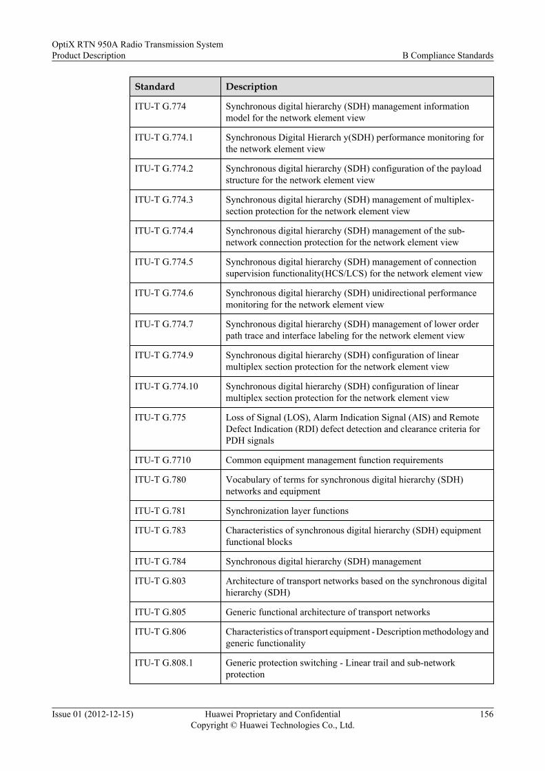
Standard Description
ITU-T G.774 Synchronous digital hierarchy (SDH) management informationmodel for the network element view
ITU-T G.774.1 Synchronous Digital Hierarch y(SDH) performance monitoring forthe network element view
ITU-T G.774.2 Synchronous digital hierarchy (SDH) configuration of the payloadstructure for the network element view
ITU-T G.774.3 Synchronous digital hierarchy (SDH) management of multiplex-section protection for the network element view
ITU-T G.774.4 Synchronous digital hierarchy (SDH) management of the sub-network connection protection for the network element view
ITU-T G.774.5 Synchronous digital hierarchy (SDH) management of connectionsupervision functionality(HCS/LCS) for the network element view
ITU-T G.774.6 Synchronous digital hierarchy (SDH) unidirectional performancemonitoring for the network element view
ITU-T G.774.7 Synchronous digital hierarchy (SDH) management of lower orderpath trace and interface labeling for the network element view
ITU-T G.774.9 Synchronous digital hierarchy (SDH) configuration of linearmultiplex section protection for the network element view
ITU-T G.774.10 Synchronous digital hierarchy (SDH) configuration of linearmultiplex section protection for the network element view
ITU-T G.775 Loss of Signal (LOS), Alarm Indication Signal (AIS) and RemoteDefect Indication (RDI) defect detection and clearance criteria forPDH signals
ITU-T G.7710 Common equipment management function requirements
ITU-T G.780 Vocabulary of terms for synchronous digital hierarchy (SDH)networks and equipment
ITU-T G.781 Synchronization layer functions
ITU-T G.783 Characteristics of synchronous digital hierarchy (SDH) equipmentfunctional blocks
ITU-T G.784 Synchronous digital hierarchy (SDH) management
ITU-T G.803 Architecture of transport networks based on the synchronous digitalhierarchy (SDH)
ITU-T G.805 Generic functional architecture of transport networks
ITU-T G.806 Characteristics of transport equipment - Description methodology andgeneric functionality
ITU-T G.808.1 Generic protection switching - Linear trail and sub-networkprotection
OptiX RTN 950A Radio Transmission SystemProduct Description B Compliance Standards
Issue 01 (2012-12-15) Huawei Proprietary and ConfidentialCopyright © Huawei Technologies Co., Ltd.
156

Standard Description
ITU-T G.810 Definitions and terminology for synchronization networks
ITU-T G.811 Timing characteristics of primary reference clocks
ITU-T G.812 Timing requirements of slave clocks suitable for use as node clocksin synchronization networks
ITU-T G.813 Timing characteristics of SDH equipment slave clocks (SEC)
ITU-T G.821 Error performance of an international digital connection operating ata bit rate below the primary rate and forming part of an integratedservices digital network
ITU-T G.822 Controlled slip rate objectives on an international digital connection
ITU-T G.823 The control of jitter and wander within digital networks which arebased on the 2048 kbit/s hierarchy
ITU-T G.825 The control of jitter and wander within digital networks which arebased on the synchronous digital hierarchy (SDH)
ITU-T G.826 Error performance parameters and objectives for international,constant bit rate digital paths at or above the primary rate
ITU-T G.828 Error performance parameters and objectives for international,constant bit rate synchronous digital paths
ITU-T G.829 Error performance events for SDH multiplex and regenerator sections
ITU-T G.831 Management capabilities of transport networks based on thesynchronous digital hierarchy (SDH)
ITU-T G.832 Transport of SDH elements on PDH networks - Frame andmultiplexing structures
ITU-T G.841 Types and characteristics of SDH network protection architectures
ITU-T G.842 Inter-working of SDH network protection architectures
ITU-T G.957 Optical interfaces for equipments and systems relating to thesynchronous digital hierarchy
ITU-T G.958 Digital line systems based on the synchronous digital hierarchy foruse on optical fiber cables.
ITU-T G.7043/Y.1343
Virtual concatenation of Plesiochronous Digital Hierarchy (PDH)signals
ITU-T G.8010 Architecture of Ethernet layer networks
ITU-T G.8011 Ethernet over Transport - Ethernet services framework
ITU-T G.8011.1 Ethernet private line service
ITU-T G.8011.2 Ethernet virtual private line service
ITU-T G.8012 Ethernet UNI and Ethernet over transport NNI
OptiX RTN 950A Radio Transmission SystemProduct Description B Compliance Standards
Issue 01 (2012-12-15) Huawei Proprietary and ConfidentialCopyright © Huawei Technologies Co., Ltd.
157

Standard Description
ITU-T G.8021 Characteristics of Ethernet transport network equipment functionalblocks
ITU-T G.8110 MPLS layer network architecture
ITU-T G.8110.1 Application of MPLS in the transport network
ITU-T G.8121 Characteristics of transport MPLS equipment functional blocks
ITU-T G.8112 Interfaces for the transport MPLS (T-MPLS) hierarchy
ITU-T G.8113.1 Operations, Administration and Maintenance mechanism for MPLS-TP networks
ITU-T G.8131 Protection switching for transport MPLS (T-MPLS) networks
ITU-T G.8261/Y.1361
Timing and synchronization aspects in packet networks
ITU-T G.8262/Y.1362
Timing characteristics of synchronous Ethernet equipment slaveclock (EEC)
ITU-T G.8264 Timing distribution through packet networks
ITU-T Y.1541 Network performance objectives for IP-based services
ITU-T Y.1710 Requirements for OAM functionality for MPLS networks
ITU-T Y.1730 Requirements for OAM functions in Ethernet based networks andEthernet services
ITU-T Y.1731 OAM functions and mechanisms for Ethernet based networks
ITU-T G.8032/Y.1344
Ethernet Ring Protection Switching
ITU-T Y.1711 Operation & Maintenance mechanism for MPLS networks
ITU-T Y.1720 Protection switching for MPLS networks
ITU-T I.610 B-ISDN operation and maintenance principles and functions
ITU-T Y.1291 An architectural framework for support of quality of service (QoS) inpacket networks
B.5 IETF StandardsThe OptiX RTN 950A complies with IETF standards.
Table B-5 IETF standard
Standard Description
RFC 2819 Remote Network Monitoring Management Information Base
OptiX RTN 950A Radio Transmission SystemProduct Description B Compliance Standards
Issue 01 (2012-12-15) Huawei Proprietary and ConfidentialCopyright © Huawei Technologies Co., Ltd.
158

Standard Description
RFC 4664 Framework for layer 2 virtual private networks (L2VPNs)
RFC 3031 MPLS architecture
RFC 3469 Framework for multi-protocol label switching (MPLS)-basedrecovery
RFC 3811 Definitions of textual conventions for multiprotocol label switching(MPLS) management
RFC 3813 Multiprotocol label switching (MPLS) label switching router (LSR)management information base
RFC 3814 Multiprotocol label switching (MPLS) forwarding equivalence classto next hop label forwarding entry (FEC-To-NHLFE) managementinformation base
RFC 4221 Multiprotocol label switching (MPLS) management overview
RFC 4377 Operations and management (OAM) requirements for multi-protocollabel switched (MPLS) networks
RFC 4378 A framework for multi-protocol label switching (MPLS) operationsand management (OAM)
RFC 3032 MPLS label stack encoding
RFC 3443 Time to live (TTL) processing in multi-protocol label switching(MPLS) networks
RFC 3916 Requirements for pseudo-wire emulation edge-to-edge (PWE3)
RFC 3985 Pseudo wire emulation edge-to-edge (PWE3) architecture
RFC 4197 Requirements for edge-to-edge emulation of time divisionmultiplexed (TDM) circuits over packet switching networks
RFC 4385 Pseudowire emulation edge-to-edge (PWE3) control word for useover an MPLS PSN
RFC 4446 IANA allocations for pseudowire edge to edge emulation (PWE3)
RFC 0826 Ethernet address resolution protocol
RFC 3270 Multi-protocol label switching (MPLS) support of differentiatedservices
RFC 4448 Encapsulation methods for transport of Ethernet over MPLS networks
RFC 4553 Structure-agnostic time division multiplexing (TDM) over packet(SAToP)
RFC 5085 Pseudo wire virtual circuit connectivity verification (VCCV)
RFC 5086 Structure-Aware Time Division Multiplexed (TDM) CircuitEmulation Service over Packet Switched Network (CESoPSN)
OptiX RTN 950A Radio Transmission SystemProduct Description B Compliance Standards
Issue 01 (2012-12-15) Huawei Proprietary and ConfidentialCopyright © Huawei Technologies Co., Ltd.
159

Standard Description
RFC 4717 Encapsulation Methods for Transport of Asynchronous TransferMode (ATM) over MPLS Networks
RFC 4816 Pseudowire Emulation Edge-to-Edge (PWE3) AsynchronousTransfer Mode (ATM) Transparent Cell Transport Service
RFC 4385 Pseudowire emulation edge-to-edge (PWE3) control word for useover an MPLS PSN
RFC 5254 Requirements for Multi-Segment Pseudowire Emulation Edge-to-Edge (PWE3)
RFC 3644 Policy quality of service (QoS) Information model
RFC 2212 Specification of guaranteed quality of service
RFC 2474 Definition of the differentiated services field (DS Field) in the IPv4and IPv6 headers
RFC 2475 An architecture for differentiated services
RFC 2597 Assured forwarding PHB group
RFC 2698 A two rate three color marker
RFC 3246 An expedited forwarding PHB (Per-hop behavior)
RFC 3270 Multi-protocol label switching (MPLS) support of differentiatedservices
draft-ietf-l2vpn-oam-req-frmk-05
L2VPN OAM requirements and framework
draft-ietf-pwe3-segmented-pw-03
Segmented pseudo wire
draft-ietf-pwe3-ms-pw-requirements-03
Requirements for inter domain pseudo-wires
draft-ietf-pwe3-ms-pw-arch-02
An architecture for multi-segment pseudo wire emulation edge-to-edge
RFC1661 The Point-to-Point Protocol (PPP)
RFC1662 PPP in HDLC-like Framing
RFC1990 The PPP Multilink Protocol (MP)
RFC2686 The Multi-Class Extension to Multi-Link PPP
RFC5317 Joint Working Team (JWT) Report on MPLS ArchitecturalConsiderations for a Transport Profile
RFC5586 MPLS Generic Associated Channel
RFC5654 Requirements of an MPLS Transport Profile
OptiX RTN 950A Radio Transmission SystemProduct Description B Compliance Standards
Issue 01 (2012-12-15) Huawei Proprietary and ConfidentialCopyright © Huawei Technologies Co., Ltd.
160

Standard Description
RFC5921 A Framework for MPLS in Transport Networks
RFC5860 Requirements for Operations, Administration, and Maintenance(OAM) in MPLS Transport Networks
B.6 IEEE StandardsThe OptiX RTN 950A complies with the IEEE standards designed for Ethernet networks.
Table B-6 IEEE standard
Standard Description
IEEE 802.3 Carrier sense multiple access with collision detection (CSMA/CD)access method and physical layer specification
IEEE 802.3u Media Access Control (MAC) parameters, physical Layer, mediumattachment units, and repeater for 100 Mb/s operation, type100BASE-T
IEEE 802.3x Full Duplex Operation and Type 100BASE-T2
IEEE 802.3z Media Access Control (MAC) parameters, physical Layer, repeaterand management parameters for 1000 Mb/s operation
IEEE 802.3ah Media Access Control Parameters, Physical Layers, and ManagementParameters for Subscriber Access Networks
IEEE 802.1d Media Access Control (MAC) Bridges
IEEE 802.1q Virtual bridged local area networks
IEEE 802.1ad Virtual Bridged Local Area Networks Amendment 4: ProviderBridges
IEEE 802.1ag Virtual Bridged Local Area Networks — Amendment 5: ConnectivityFault Management
IEEE 1588v2 IEEE Standard for a Precision Clock Synchronization Protocol forNetworked Measurement and Control Systems
IEEE 802.3af Data Terminal Equipment (DTE) Power Via Media DependentInterface (MDI)
IEEE 802.3at Data Terminal Equipment (DTE) Power via the Media DependentInterface (MDI) Enhancements
B.7 MEF StandardsThe OptiX RTN 950A complies with MEF standards.
OptiX RTN 950A Radio Transmission SystemProduct Description B Compliance Standards
Issue 01 (2012-12-15) Huawei Proprietary and ConfidentialCopyright © Huawei Technologies Co., Ltd.
161

Table B-7 MEF standard
Standard Description
MEF 2 Requirements and framework for Ethernet service protection in metroEthernet networks
MEF 4 Metro Ethernet network architecture framework - Part 1: genericframework
MEF 9 Abstract Test Suite for Ethernet Services at the UNI
MEF 10 Ethernet services attributes phase 1
MEF 14 Abstract Test Suite for Traffic Management Phase 1
MEF 17 Service OAM Framework and Requirements
MEF 18 Abstract Test Suite for Circuit Emulation Services
MEF 21 Abstract Test Suite for UNI Type 2 Part 1: Link OAM
MEF 22 Mobile Backhaul Implementation Agreement Phase 1
B.8 AF StandardsThe OptiX RTN 950A complies with AF standards.
Table B-8 AF standard
Standard Description
AF-PHY-0086.001 Inverse Multiplexing for ATM Specification Version 1.1
AF-TM-0121.000 Traffic Management Specification
B.9 Environmental StandardsThe OptiX RTN 950A complies with the environmental standards designed for split-mountmicrowave equipment.
Table B-9 environmental standard
Standard Description
EN 55022 Limits and Methods of Measurement of Radio DisturbanceCharacteristics of Information Technology Equipment
CISPR 22 Limits and methods of measurement of radio disturbancecharacteristics of information
OptiX RTN 950A Radio Transmission SystemProduct Description B Compliance Standards
Issue 01 (2012-12-15) Huawei Proprietary and ConfidentialCopyright © Huawei Technologies Co., Ltd.
162

Standard Description
ETSI EN 301 489-1 Electromagnetic compatibility and Radio spectrum Matters (ERM);Electromagnetic Compatibility (EMC) standard for radio equipmentand services; Part 1: Common technical requirements
ETSI EN 301 489-4 Electromagnetic compatibility and Radio spectrum Matters (ERM);Electromagnetic Compatibility (EMC) standard for radio equipmentand services; Part 4: Specific conditions for fixed radio links andancillary equipment and services
EN 60950-1 Information technology equipment-Safety-Part 1: Generalrequirements
UL 60950-1 Information technology equipment-Safety-Part 1: Generalrequirements
IEC 60825-1 Safety of laser products-Part 1: Equipment classification,requirements and user's guide
IEC 60825-2 Safety of laser products-Part 2: Safety of optical fiber communicationsystems (OFCS)
IEC 60950-1 Information technology equipment-Safety-Part 1: Generalrequirements
IEC 60950-22(Outdoor Unit)
Information technology equipment-Safety-Part 22: Equipment to beinstalled outdoors
IEC 61000-4-2 Electromagnetic compatibility (EMC) Part 2: Testing andmeasurement techniques Section 2: Electrostatic discharge immunitytest Basic EMC Publication
IEC 61000-4-3 Electromagnetic compatibility; Part 3: Testing and measurementtechniques Section 3 radio frequency electromagnetic fields;immunity test.
IEC 61000-4-4 Electromagnetic compatibility (EMC) Part 4: Testing andmeasurement techniques Section 4: Electrical fast transient/burstimmunity test Basic EMC publication
IEC 61000-4-5 Electromagnetic compatibility (EMC) Part 5: Testing andmeasurement techniques Section 5: Surge immunity test
IEC 61000-4-6 Electromagnetic compatibility: Part 6: Testing and measurementtechniques: Section 6 conducted disturbances induced by radio-frequency fields; immunity test
IEC 721-3-1 Classes1K4/1Z2/1Z3/1Z5/1B2/1C2/1S3/1M2
Classification of environmental conditions - Part 3: Classification ofgroups of environmental parameters and their severities - Section 1:Storage Classes 1K4/1Z2/1Z3/1Z5/1B2/1C2/1S3/1M2
IEC 721-3-2 Classes2K4/2B2/2C2/2S2/2M2
Classification of environmental conditions - Part 3: Classification ofgroups of environmental parameters and their severities - Section 2:Transportation Classes 2K4/2B2/2C2/2S2/2M2
OptiX RTN 950A Radio Transmission SystemProduct Description B Compliance Standards
Issue 01 (2012-12-15) Huawei Proprietary and ConfidentialCopyright © Huawei Technologies Co., Ltd.
163

Standard Description
IEC 721-3-3 Classes3K5/3Z2/3Z4/3B2/3C2(3C1)/3S2/3M2(Indoor Unit)
Classification of environmental conditions - Part 3: Classification ofgroups of environmental parameters and their severities - Section 3:Stationary use at weather protected locations Classes3K5/3Z2/3Z4/3B2/3C2(3C1)/3S2/3M2
IEC 721-3-4 Classes4K2/4Z5/4Z7/4B1/4C2(4C3)/4S2/4M5(Outdoor Unit)
Classification of environmental conditions - Part 3: Classification ofgroups of environmental parameters and their severities - Section 4:Stationary use at non-weather protected locations. Classes4K2/4Z5/4Z7/4B1/4C2(4C3)/4S2/4M5
ETSI EN 300019-1-1 Class 1.2
Environmental conditions and environmental tests fortelecommunications equipment; Part 1-1: Classification ofenvironmental conditions; Storage Class 1.2
ETSI EN 300019-1-2 Class 2.3
Environmental conditions and environmental tests fortelecommunications equipment; Part 1-2: Classification ofenvironmental conditions; Transportation Class 2.3
ETSI EN 300019-1-3 Class 3.2(Indoor Unit)
Environmental conditions and environmental tests fortelecommunications equipment; Part 1-3: Classification ofenvironmental conditions; Stationary use at weather-protectedlocations; Class 3.2
ETSI EN 300019-1-4 Class 4.1(Outdoor Unit)
Environmental conditions and environmental tests fortelecommunications equipment; Part 1-4: Classification ofenvironmental conditions; Stationary use at non-weather-protectedlocations Class 4.1
EN 300 132-2 Environmental Engineering (EE); Power supply interface at the inputto telecommunications equipment; Part 2: Operated by direct current(dc)
EN 300 119 Environmental Engineering (EE); European telecommunicationstandard for equipment practice;
TR 102 489 V1.1.1 Thermal Management Guidance for equipment and its deployment
ETS 300 753 Equipment Engineering (EE);Acoustic noise emitted bytelecommunications equipment
IEC 60215 Safety requirements for radio transmitting equipment
IEC 60825 Safety of laser products
IEC 60657 Non-ionizing radiation hazards in the frequency range from 10 MHzto 300 000 MHz
IEC 60297 Dimensions of mechanical structures of the 482.6 mm (19 in) series
IEC 60529 Degrees of protection provided by enclosures
IEC 60068 Environmental Testing
OptiX RTN 950A Radio Transmission SystemProduct Description B Compliance Standards
Issue 01 (2012-12-15) Huawei Proprietary and ConfidentialCopyright © Huawei Technologies Co., Ltd.
164

Standard Description
EN 61000-3-2 Electromagnetic compatibility (EMC) -Part 3-2: Limits -Limits forharmonic current emissions (equipment input current< 16 A perphase)
EN 61000-3-3 Electromagnetic compatibility (EMC) -Part 3-3: Limits -Limitationof voltage changes, voltage fluctuations and flicker in public low-voltage supply systems, for equipment with rated current < - 16 A perphase and not subject to conditional connection
EN 50383 Basic standard for the calculation and measurement ofelectromagnetic field strength and SAR related to human exposurefrom radio base stations and fixed terminal stations for wirelesstelecommunications system (110 MHz - 40 GHz)
EN 50385 Product standard to demonstrate the compliances of radio basestations and fixed terminal stations for wireless telecommunicationsystems with the basic restrictions or the reference levels related tohuman exposure to ratio frequency electromagnetic fields(110MHz-40GHz) -General public
IEC 68-2-2 Environmental testing: Dry heat.
IEC 68-2-14 Environmental testing: Change of temperature.
IEC 68-2-30 Environmental testing: Damp heat, cyclic: (12 + 12 hour cycle).
OptiX RTN 950A Radio Transmission SystemProduct Description B Compliance Standards
Issue 01 (2012-12-15) Huawei Proprietary and ConfidentialCopyright © Huawei Technologies Co., Ltd.
165

C Glossary
Numerics
3G See 3rd Generation.
3GPP 3rd Generation Partnership Project
3rd Generation (3G) The third generation of digital wireless technology, as defined by the InternationalTelecommunications Union (ITU). Third generation technology is expected to deliverdata transmission speeds between 144 kbit/s and 2 Mbit/s, compared to the 9.6 kbit/s to19.2 kbit/s offered by second generation technology.
802.1Q in 802.1Q A VLAN feature that allows the equipment to add a VLAN tag to a tagged frame. Theimplementation of QinQ is to add a public VLAN tag to a frame with a private VLANtag to allow the frame with double VLAN tags to be transmitted over the serviceprovider's backbone network based on the public VLAN tag. This provides a Layer 2VPN tunnel for customers and enables transparent transmission of packets over privateVLANs.
A
A/D analog/digit
ABR See available bit rate.
ACAP See adjacent channel alternate polarization.
ACL See access control list.
ADC analog to digital converter
ADM add/drop multiplexer
AF See assured forwarding.
AIS alarm indication signal
ALS See automatic laser shutdown.
AM See adaptive modulation.
APS automatic protection switching
ARP See Address Resolution Protocol.
ASBR See autonomous system boundary router.
OptiX RTN 950A Radio Transmission SystemProduct Description C Glossary
Issue 01 (2012-12-15) Huawei Proprietary and ConfidentialCopyright © Huawei Technologies Co., Ltd.
166

ASIC See application-specific integrated circuit.
ATM asynchronous transfer mode
ATPC See automatic transmit power control.
AU See administrative unit.
Address ResolutionProtocol (ARP)
An Internet Protocol used to map IP addresses to MAC addresses. It allows hosts androuters to determine the link layer addresses through ARP requests and ARP responses.
access control list(ACL)
A list of entities, together with their access rights, which are authorized to have accessto a resource.
adaptive modulation(AM)
A technology that is used to automatically adjust the modulation mode according to thechannel quality. When the channel quality is favorable, the equipment uses a high-efficiency modulation mode to improve the transmission efficiency and the spectrumutilization of the system. When the channel quality is degraded, the equipment uses thelow-efficiency modulation mode to improve the anti-interference capability of the linkthat carries high-priority services.
adjacent channelalternate polarization(ACAP)
A channel configuration method, which uses two adjacent channels (a horizontalpolarization wave and a vertical polarization wave) to transmit two signals.
administrative unit(AU)
The information structure which provides adaptation between the higher order path layerand the multiplex section layer. It consists of an information payload (the higher orderVC) and an AU pointer which indicates the offset of the payload frame start relative tothe multiplex section frame start.
alarm suppression An alarm management method. Alarms that are set to be suppressed are not reportedfrom NEs any more.
analog signal A signal in which information is represented with a continuously variable physicalquantity, such as voltage. Because of this constant changing of the wave shape withregard to its passing a given point in time or space, an analog signal might have a virtuallyindefinite number of states or values. This contrasts with a digital signal that is expressedas a square wave and therefore has a very limited number of discrete states. Analogsignals, with complicated structures and narrow bandwidth, are vulnerable to externalinterference.
application-specificintegrated circuit(ASIC)
A special type of chip that starts out as a nonspecific collection of logic gates. Late inthe manufacturing process, a layer is added to connect the gates for a specific function.By changing the pattern of connections, the manufacturer can make the chip suitable formany needs.
assured forwarding(AF)
One of the four per-hop behaviors (PHB) defined by the Diff-Serv workgroup of IETF.It is suitable for certain key data services that require assured bandwidth and short delay.For traffic within the bandwidth limit, AF assures quality in forwarding. For traffic thatexceeds the bandwidth limit, AF degrades the service class and continues to forward thetraffic instead of discarding the packets.
attenuator A device used to increase the attenuation of an Optical Fiber Link. Generally used toensure that the signal at the receive end is not too strong.
automatic lasershutdown (ALS)
A technique (procedure) to automatically shutdown the output power of laser transmittersand optical amplifiers to avoid exposure to hazardous levels.
automatic transmitpower control (ATPC)
A method of adjusting the transmit power based on fading of the transmit signal detectedat the receiver
OptiX RTN 950A Radio Transmission SystemProduct Description C Glossary
Issue 01 (2012-12-15) Huawei Proprietary and ConfidentialCopyright © Huawei Technologies Co., Ltd.
167

autonomous systemboundary router(ASBR)
A router that exchanges routing information with other ASs.
available bit rate (ABR) A kind of service categories defined by the ATM forum. ABR only provides possibleforwarding service and applies to the connections that does not require the real-timequality. It does not provide any guarantee in terms of cell loss or delay.
B
B-ISDN See broadband integrated services digital network.
BDI See backward defect indication.
BE See best effort.
BER bit error rate
BFD See Bidirectional Forwarding Detection.
BGP Border Gateway Protocol
BIOS See basic input/output system.
BIP See bit interleaved parity.
BPDU See bridge protocol data unit.
BSC See base station controller.
BTS base transceiver station
BidirectionalForwarding Detection(BFD)
A simple Hello protocol, similar to the adjacent detection in the route protocol. Twosystems periodically send BFD detection messages on the channel between the twosystems. If one system does not receive the detection message from the other system fora long time, you can infer that the channel is faulty. Under some conditions, the TX andRX rates between systems need to be negotiated to reduce traffic load.
backbone network A network that forms the central interconnection for a connected network. Thecommunication backbone for a country is WAN. The backbone network is an importantarchitectural element for building enterprise networks. It provides a path for the exchangeof information between different LANs or subnetworks. A backbone can tie togetherdiverse networks in the same building, in different buildings in a campus environment,or over wide areas. Generally, the backbone network's capacity is greater than thenetworks connected to it.
backward defectindication (BDI)
A function that the sink node of a LSP, when detecting a defect, uses to inform theupstream end of the LSP of a downstream defect along the return path.
bandwidth A range of transmission frequencies that a transmission line or channel can carry in anetwork. In fact, it is the difference between the highest and lowest frequencies thetransmission line or channel. The greater the bandwidth, the faster the data transfer rate.
base station controller(BSC)
A logical entity that connects the BTS with the MSC in a GSM/CDMA network. Itinterworks with the BTS through the Abis interface, the MSC through the A interface.It provides the following functions: radio resource management, base stationmanagement, power control, handover control, and traffic measurement. One BSCcontrols and manages one or more BTSs in an actual network.
OptiX RTN 950A Radio Transmission SystemProduct Description C Glossary
Issue 01 (2012-12-15) Huawei Proprietary and ConfidentialCopyright © Huawei Technologies Co., Ltd.
168

basic input/outputsystem (BIOS)
A firmware stored in the computer mainboard. It contains basic input/output controlprograms, power-on self test (POST) programs, bootstraps, and system settinginformation. The BIOS provides hardware setting and control functions for the computer.
baud rate The number of times per second the signal can change on a transmission line. Commonly,the transmission line uses only two signal states, making the baud rate equal to thenumber of bits per second that can be transferred. The underlying transmission techniquemay use some of the bandwidth, so it may not be the case that user data transfers at theline's specified bit rate.
best effort (BE) A traditional IP packet transport service. In this service, the diagrams are forwardedfollowing the sequence of the time they reach. All diagrams share the bandwidth of thenetwork and routers. The amount of resource that a diagram can use depends of the timeit reaches. BE service does not ensure any improvement in delay time, jitter, packet lossratio, and high reliability.
bit interleaved parity(BIP)
A method of error monitoring. With even parity an X-bit code is generated by equipmentat the transmit end over a specified portion of the signal in such a manner that the firstbit of the code provides even parity over the first bit of all X-bit sequences in the coveredportion of the signal, the second bit provides even parity over the second bit of all X-bitsequences within the specified portion, and so on. Even parity is generated by setting theBIP-X bits so that there is an even number of 1s in each monitored partition of the signal.A monitored partition comprises all bits which are in the same bit position within the X-bit sequences in the covered portion of the signal. The covered portion includes the BIP-X.
bridge A device that connects two or more networks and forwards packets among them. Bridgesoperate at the physical network level. Bridges differ from repeaters because bridges storeand forward complete packets, while repeaters forward all electrical signals. Bridgesdiffer from routers because bridges use physical addresses, while routers use IPaddresses.
bridge protocol dataunit (BPDU)
The data messages that are exchanged across the switches within an extended LAN thatuses a spanning tree protocol (STP) topology. BPDU packets contain information onports, addresses, priorities and costs and ensure that the data ends up where it wasintended to go. BPDU messages are exchanged across bridges to detect loops in anetwork topology. The loops are then removed by shutting down selected bridgesinterfaces and placing redundant switch ports in a backup, or blocked, state.
broadband integratedservices digital network(B-ISDN)
A standard defined by the ITU-T to handle high-bandwidth applications, such as voice.It currently uses the ATM technology to transmit data over SONNET-based circuits at155 to 622 Mbit/s or higher speed.
broadcast A means of delivering information to all members in a network. The broadcast range isdetermined by the broadcast address.
broadcast domain A group of network stations that receives broadcast packets originating from any devicewithin the group. The broadcast domain also refers to the set of ports between which adevice forwards a multicast, broadcast, or unknown destination frame.
C
CAR committed access rate
CBR See constant bit rate.
CBS See committed burst size.
OptiX RTN 950A Radio Transmission SystemProduct Description C Glossary
Issue 01 (2012-12-15) Huawei Proprietary and ConfidentialCopyright © Huawei Technologies Co., Ltd.
169

CC See continuity check.
CCDP See co-channel dual polarization.
CDMA See Code Division Multiple Access.
CE See customer edge.
CES See circuit emulation service.
CGMP Cisco Group Management Protocol
CIST See Common and Internal Spanning Tree.
CLNP connectionless network protocol
CM connection management
CORBA See Common Object Request Broker Architecture.
CPU See central processing unit.
CRC See cyclic redundancy check.
CSES consecutive severely errored second
CSMA/CD See carrier sense multiple access with collision detection.
CTC common transmit clock
CW control word
Code Division MultipleAccess (CDMA)
A communication scheme that forms different code sequences by using the frequencyexpansion technology. Subscribers with different addresses can use different codesequences for multi-address connection.
Common ObjectRequest BrokerArchitecture (CORBA)
A specification developed by the Object Management Group in 1992 in which pieces ofprograms (objects) communicate with other objects in other programs, even if the twoprograms are written in different programming languages and are running on differentplatforms. A program makes its request for objects through an object request broker, orORB, and thus does not need to know the structure of the program from which the objectcomes. CORBA is designed to work in object-oriented environments. See also IIOP,object (definition 2), Object Management Group, object-oriented.
Common and InternalSpanning Tree (CIST)
The single spanning tree jointly calculated by STP and RSTP, the logical connectivityusing MST bridges and regions, and MSTP. The CIST ensures that all LANs in thebridged local area network are simply and fully connected.
cable tie A tape used to bind cables.
carrier sense multipleaccess with collisiondetection (CSMA/CD)
Carrier sense multiple access with collision detection (CSMA/CD) is a computernetworking access method in which:
l A carrier sensing scheme is used.l A transmitting data station that detects another signal while transmitting a frame,
stops transmitting that frame, transmits a jam signal, and then waits for a randomtime interval before trying to send that frame again.
central processing unit(CPU)
The computational and control unit of a computer. The CPU is the device that interpretsand executes instructions. The CPU has the ability to fetch, decode, and executeinstructions and to transfer information to and from other resources over the computer'smain data-transfer path, the bus.
OptiX RTN 950A Radio Transmission SystemProduct Description C Glossary
Issue 01 (2012-12-15) Huawei Proprietary and ConfidentialCopyright © Huawei Technologies Co., Ltd.
170

channel A telecommunication path of a specific capacity and/or at a specific speed between twoor more locations in a network. Channels can be established through wire, radio(microwave), fiber or a combination of the three. The amount of information transmittedper second in a channel is the information transmission speed, expressed in bits persecond. For example, b/s, kb/s, Mb/s, Gb/s, and Tb/s.
circuit emulationservice (CES)
A function with which the E1/T1 data can be transmitted through ATM networks. At thetransmission end, the interface module packs timeslot data into ATM cells. These ATMcells are sent to the reception end through the ATM network. At the reception end, theinterface module re-assigns the data in these ATM cells to E1/T1 timeslots. The CEStechnology guarantees that the data in E1/T1 timeslots can be recovered to the originalsequence at the reception end.
clock tracing The method to keep the time on each node synchronized with a clock source in a network.
co-channel dualpolarization (CCDP)
A channel configuration method, which uses a horizontal polarization wave and a verticalpolarization wave to transmit two signals. The Co-Channel Dual Polarization has twicethe transmission capacity of the single polarization.
committed burst size(CBS)
A parameter used to define the capacity of token bucket C, that is, the maximum burstIP packet size when the information is transferred at the committed information rate.This parameter must be larger than 0. It is recommended that this parameter should benot less than the maximum length of the IP packet that might be forwarded.
constant bit rate (CBR) A kind of service categories defined by the ATM forum. CBR transfers cells based onthe constant bandwidth. It is applicable to service connections that depend on preciseclocking to ensure undistorted transmission.
continuity check (CC) Ethernet CFM can detect the connectivity between MEPs. The detection is achieved afterMEPs transmit Continuity Check Messages (CCMs) periodically.
cross polarizationinterferencecancellation (XPIC)
A technology used in the case of the Co-Channel Dual Polarization (CCDP) to eliminatethe cross-connect interference between two polarization waves in the CCDP.
customer edge (CE) A part of BGP/MPLS IP VPN model. It provides interfaces for direct connection to theService Provider (SP) network. A CE can be a router, switch, or host.
cyclic redundancycheck (CRC)
A procedure used in checking for errors in data transmission. CRC error checking usesa complex calculation to generate a number based on the data transmitted. The sendingdevice performs the calculation before transmission and includes it in the packet that itsends to the receiving device. The receiving device repeats the same calculation aftertransmission. If both devices obtain the same result, it is assumed that the transmissionwas error free. The procedure is known as a redundancy check because each transmissionincludes not only data but extra (redundant) error-checking values.
D
DC direct current
DC-C See DC-return common (with ground).
DC-I See DC-return isolate (with ground).
DC-return common(with ground) (DC-C)
A power system, in which the BGND of the DC return conductor is short-circuited withthe PGND on the output side of the power supply cabinet and also on the line betweenthe output of the power supply cabinet and the electric equipment.
OptiX RTN 950A Radio Transmission SystemProduct Description C Glossary
Issue 01 (2012-12-15) Huawei Proprietary and ConfidentialCopyright © Huawei Technologies Co., Ltd.
171

DC-return isolate (withground) (DC-I)
A power system, in which the BGND of the DC return conductor is short-circuited withthe PGND on the output side of the power supply cabinet and is isolated from the PGNDon the line between the output of the power supply cabinet and the electric equipment.
DCC See data communications channel.
DCN See data communication network.
DDF digital distribution frame
DDN See digital data network.
DE discard eligible
DM See delay measurement.
DS boundary node A DS node that connects one DS domain to a node either in another DS domain or in adomain that is not DS-capable.
DS interior node A DS node located at the center of a DS domain. It is a non-DS boundary node.
DS node A DS-compliant node, which is subdivided into DS boundary node and ID interior node.
DSCP See differentiated services code point.
DVMRP See Distance Vector Multicast Routing Protocol.
DiffServ See Differentiated Services.
Differentiated Services(DiffServ)
An IETF standard that defines a mechanism for controlling and forwarding traffic in adifferentiated manner based on CoS settings to handle network congestion.
Distance VectorMulticast RoutingProtocol (DVMRP)
An Internet gateway protocol mainly based on the RIP. The protocol implements a typicaldense mode IP multicast solution. The DVMRP protocol uses IGMP to exchange routingdatagrams with its neighbors.
data communicationnetwork (DCN)
A communication network used in a TMN or between TMNs to support the datacommunication function.
data communicationschannel (DCC)
The data channel that uses the D1–D12 bytes in the overhead of an STM-N signal totransmit information about operation, management, maintenance and provision(OAM&P) between NEs. The DCC channels that are composed of bytes D1–D3 arereferred to as the 192 kbit/s DCC-R channel. The other DCC channels that are composedof bytes D4–D12 are referred to as the 576 kbit/s DCC-M channel.
delay measurement(DM)
The time elapsed since the start of transmission of the first bit of the frame by a sourcenode until the reception of the last bit of the loopbacked frame by the same source node,when the loopback is performed at the frame's destination node.
differentiated servicescode point (DSCP)
According to the QoS classification standard of the Differentiated Service (Diff-Serv),the type of services (ToS) field in the IP header consists of six most significant bits andtwo currently unused bits, which are used to form codes for priority marking.Differentiated services code point (DSCP) is the six most important bits in the ToS. It isthe combination of IP precedence and types of service. The DSCP value is used to ensurethat routers supporting only IP precedence can be used because the DSCP value iscompatible with IP precedence. Each DSCP maps a per-hop behavior (PHB). Therefore,terminal devices can identify traffic using the DSCP value.
digital data network(DDN)
A high-quality data transport tunnel that combines the digital channel (such as fiberchannel, digital microwave channel, or satellite channel) and the cross multiplextechnology.
OptiX RTN 950A Radio Transmission SystemProduct Description C Glossary
Issue 01 (2012-12-15) Huawei Proprietary and ConfidentialCopyright © Huawei Technologies Co., Ltd.
172

digital modulation A method that controls the changes in amplitude, phase, and frequency of the carrierbased on the changes in the baseband digital signal. In this manner, the information canbe transmitted by the carrier.
dual-polarized antenna An antenna intended to simultaneously radiate or receive two independent radio wavesorthogonally polarized.
E
E-Aggr See Ethernet aggregation.
E-LAN See Ethernet local area network.
E-Line See Ethernet line.
ECC See embedded control channel.
EMC See electromagnetic compatibility.
EMI See electromagnetic interference.
EPL See Ethernet private line.
EPLAN See Ethernet private LAN service.
EPLD See erasable programmable logical device.
ERPS Ethernet ring protection switching
ESD electrostatic discharge
ETS European Telecommunication Standards
ETSI See European Telecommunications Standards Institute.
EVPL See Ethernet virtual private line.
EVPLAN See Ethernet virtual private LAN service.
Ethernet A LAN technology that uses Carrier Sense Multiple Access/Collision Detection. Thespeed of an Ethernet interface can be 10 Mbit/s, 100 Mbit/s, 1000 Mbit/s or 10000 Mbit/s. An Ethernet network features high reliability and is easy to maintain.
Ethernet aggregation(E-Aggr)
A type of Ethernet service that is based on a multipoint-to-point EVC (Ethernet virtualconnection).
Ethernet line (E-Line) A type of Ethernet service that is based on a point-to-point EVC (Ethernet virtualconnection).
Ethernet local areanetwork (E-LAN)
A type of Ethernet service that is based on a multipoint-to-multipoint EVC (Ethernetvirtual connection).
Ethernet private LANservice (EPLAN)
A type of Ethernet service provided by SDH, PDH, ATM, or MPLS networks. Thisservice is carried over a dedicated bridge and point-to-multipoint connections.
Ethernet private line(EPL)
A type of Ethernet service that is provided with dedicated bandwidth and point-to-pointconnections on an SDH, PDH, ATM, or MPLS server layer network.
Ethernet virtualprivate LAN service(EVPLAN)
A type of Ethernet service provided by SDH, PDH, ATM, or MPLS networks. Thisservice is carried over a shared bridge and point-to-multipoint connections.
Ethernet virtualprivate line (EVPL)
A type of Ethernet service provided by SDH, PDH, ATM, or MPLS networks. Thisservice is carried over a shared bridge and point-to-point connections.
OptiX RTN 950A Radio Transmission SystemProduct Description C Glossary
Issue 01 (2012-12-15) Huawei Proprietary and ConfidentialCopyright © Huawei Technologies Co., Ltd.
173

EuropeanTelecommunicationsStandards Institute(ETSI)
A standards-setting body in Europe. Also the standards body responsible for GSM.
electromagneticcompatibility (EMC)
A condition which prevails when telecommunications equipment is performing itsindividually designed function in a common electromagnetic environment withoutcausing or suffering unacceptable degradation due to unintentional electromagneticinterference to or from other equipment in the same environment.
electromagneticinterference (EMI)
Any electromagnetic disturbance that interrupts, obstructs, or otherwise degrades orlimits the effective performance of electronics/electrical equipment.
embedded controlchannel (ECC)
A logical channel that uses a data communications channel (DCC) as its physical layer,to enable transmission of operation, administration, and maintenance (OAM)information between NEs.
engineering label A mark on a cable, a subrack, or a cabinet for identification.
erasableprogrammable logicaldevice (EPLD)
A logical array device which can be used to implement the required functions byprogramming the array. In addition, a user can modify and program the array repeatedlyuntil the program meets the requirement.
F
FD See frequency diversity.
FDDI See fiber distributed data interface.
FDI See forward defect indication.
FE See fast Ethernet.
FEC See forward error correction.
FFD fast failure detection
FFD packet A path failure detection method independent from CV. Different from a CV packet, thefrequency for generating FFD packets is configurable to satisfy different servicerequirements. By default, the frequency is 20/s. An FFD packet contains information thesame as that in a CV packet. The destination end LSR processes FFD packets in the sameway for processing CV packets.
FIFO See first in first out.
FPGA See field programmable gate array.
FTP File Transfer Protocol
fast Ethernet (FE) Any network that supports transmission rate of 100 Mbit/s. The Fast Ethernet is 10 timesfaster than 10BaseT, and inherits frame format, MAC addressing scheme, MTU, and soon. Fast Ethernet is extended based on the IEEE802.3 standard, and it uses the followingthree types of transmission media: 100BASE-T4 (4 pairs of phone twisted-pair cables),100BASE-TX (2 pairs of data twisted-pair cables), and 100BASE-FX (2-core opticalfibers).
fiber distributed datainterface (FDDI)
A standard developed by the American National Standards Institute (ANSI) for high-speed fiber-optic local area networks (LANs). FDDI provides specifications fortransmission rates of 100 megabits (100 million bits) per second on networks based onthe token ring network.
OptiX RTN 950A Radio Transmission SystemProduct Description C Glossary
Issue 01 (2012-12-15) Huawei Proprietary and ConfidentialCopyright © Huawei Technologies Co., Ltd.
174

field programmablegate array (FPGA)
A type of semi-customized circuit used in the application specific integrated circuit(ASIC) field. It is developed on the basis of the programmable components, such as thePAL, GAL, and EPLD. It not only remedies the defects of customized circuits but alsoovercomes the disadvantage of the original programmable components in terms of thelimited number of gate arrays.
first in first out (FIFO) A stack management mechanism. The first saved data is first read and invoked.
forward defectindication (FDI)
A packet generated and traced forward to the sink node of the LSP by the node that firstdetects defects. It includes fields to indicate the nature of the defect and its location. Itsprimary purpose is to suppress alarms being raised at affected higher level client LSPsand (in turn) their client layers.
forward errorcorrection (FEC)
A bit error correction technology that adds the correction information to the payload atthe transmit end. Based on the correction information, the bit errors generated duringtransmission are corrected at the receive end.
fragmentation A process of breaking a packet into smaller units when transmitting over a network nodethat does not support the original size of the packet.
frequency diversity(FD)
A diversity scheme in which two or more microwave frequencies with a certainfrequency interval are used to transmit/receive the same signal and selection is thenperformed between the two signals to ease the impact of fading.
G
GCRA generic cell rate algorithm
GE See gigabit Ethernet.
GFC generic flow control
GFP See Generic Framing Procedure.
GNE See gateway network element.
GPS See Global Positioning System.
GTS See generic traffic shaping.
GUI graphical user interface
Generic FramingProcedure (GFP)
A framing and encapsulation method which can be applied to any data type. It has beenstandardized by ITU-T SG15.
Global PositioningSystem (GPS)
A global navigation satellite system. It provides reliable positioning, navigation, andtiming services to worldwide users.
gateway A device that connects two network segments using different protocols. It is used totranslate the data in the two network segments.
gateway networkelement (GNE)
A network element that is used for communication between the NE application layer andthe NM application layer.
generic traffic shaping(GTS)
A traffic control measure that proactively adjusts the output speed of the traffic. This isto adapt the traffic to network resources that can be provided by the downstream routerto avoid packet discarding and congestion.
OptiX RTN 950A Radio Transmission SystemProduct Description C Glossary
Issue 01 (2012-12-15) Huawei Proprietary and ConfidentialCopyright © Huawei Technologies Co., Ltd.
175

gigabit Ethernet (GE) A collection of technologies for transmitting Ethernet frames at a rate of a gigabit persecond, as defined by the IEEE 802.3z standard. GE is compatible with 10 Mbit/s and100 Mbit/s Ethernet. It runs at 1000 Mbit/s. Gigabit Ethernet uses a private medium, andit does not support coaxial cables or other cables. It also supports the channels in thebandwidth mode. If Gigabit Ethernet is, however, deployed to be the private bandwidthsystem with a bridge (switch) or a router as the center, it gives full play to the performanceand the bandwidth. In the network structure, Gigabit Ethernet uses full duplex links thatare private, causing the length of the links to be sufficient for backbone applications ina building and campus.
H
HDLC High-Level Data Link Control
HQoS See hierarchical quality of service.
HSDPA See High Speed Downlink Packet Access.
HSM hitless switch mode
High Speed DownlinkPacket Access(HSDPA)
A modulating-demodulating algorithm put forward in 3GPP R5 to meet the requirementfor asymmetric uplink and downlink transmission of data services. It enables themaximum downlink data service rate to reach 14.4 Mbit/s without changing theWCDMA network topology.
hierarchical quality ofservice (HQoS)
A type of QoS that controls the traffic of users and performs the scheduling accordingto the priority of user services. HQoS has an advanced traffic statistics function, and theadministrator can monitor the usage of bandwidth of each service. Hence, the bandwidthcan be allocated reasonably through traffic analysis.
hybrid radio The hybrid transmission of Native E1 and Native Ethernet signals. Hybrid radio supportsthe AM function.
I
I/O input/output
ICMP See Internet Control Message Protocol.
IDU See indoor unit.
IEEE See Institute of Electrical and Electronics Engineers.
IETF See Internet Engineering Task Force.
IF See intermediate frequency.
IGMP See Internet Group Management Protocol.
IGMP snooping A multicast constraint mechanism running on a layer 2 device. This protocol managesand controls the multicast group by listening to and analyzing Internet GroupManagement Protocol (IGMP) packets between hosts and Layer 3 devices. In thismanner, the spread of the multicast data on layer 2 network can be prevented efficiently.
IGP See Interior Gateway Protocol.
IMA See inverse multiplexing over ATM.
IP Internet Protocol
IPv4 See Internet Protocol version 4.
OptiX RTN 950A Radio Transmission SystemProduct Description C Glossary
Issue 01 (2012-12-15) Huawei Proprietary and ConfidentialCopyright © Huawei Technologies Co., Ltd.
176

IPv6 See Internet Protocol version 6.
IS-IS See Intermediate System to Intermediate System.
ISDN integrated services digital network
ISO International Organization for Standardization
IST internal spanning tree
ITU See International Telecommunication Union.
ITU-T See International Telecommunication Union-Telecommunication StandardizationSector.
IWF Interworking Function
Institute of Electricaland ElectronicsEngineers (IEEE)
A society of engineering and electronics professionals based in the United States butboasting membership from numerous other countries. The IEEE focuses on electrical,electronics, computer engineering, and science-related matters.
Interior GatewayProtocol (IGP)
A routing protocol that is used within an autonomous system. The IGP runs in small-sized and medium-sized networks. The commonly used IGPs are the routing informationprotocol (RIP), the interior gateway routing protocol (IGRP), the enhanced IGRP(EIGRP), and the open shortest path first (OSPF).
Intermediate System toIntermediate System(IS-IS)
A protocol used by network devices (routers) to determine the best way to forwarddatagram or packets through a packet-based network.
InternationalTelecommunicationUnion (ITU)
A United Nations agency, one of the most important and influential recommendationbodies, responsible for recommending standards for telecommunication (ITU-T) andradio networks (ITU-R).
InternationalTelecommunicationUnion-TelecommunicationStandardization Sector(ITU-T)
An international body that develops worldwide standards for telecommunicationstechnologies. These standards are grouped together in series which are prefixed with aletter indicating the general subject and a number specifying the particular standard. Forexample, X.25 comes from the "X" series which deals with data networks and opensystem communications and number "25" deals with packet switched networks.
Internet ControlMessage Protocol(ICMP)
A network-layer (ISO/OSI level 3) Internet protocol that provides error correction andother information relevant to IP packet processing. For example, it can let the IP softwareon one machine inform another machine about an unreachable destination. See alsocommunications protocol, IP, ISO/OSI reference model, packet (definition 1).
Internet EngineeringTask Force (IETF)
A worldwide organization of individuals interested in networking and the Internet.Managed by the Internet Engineering Steering Group (IESG), the IETF is charged withstudying technical problems facing the Internet and proposing solutions to the InternetArchitecture Board (IAB). The work of the IETF is carried out by various working groupsthat concentrate on specific topics such as routing and security. The IETF is the publisherof the specifications that led to the TCP/IP protocol standard.
Internet GroupManagement Protocol(IGMP)
One of the TCP/IP protocols for managing the membership of Internet Protocol multicastgroups. It is used by IP hosts and adjacent multicast routers to establish and maintainmulticast group memberships.
OptiX RTN 950A Radio Transmission SystemProduct Description C Glossary
Issue 01 (2012-12-15) Huawei Proprietary and ConfidentialCopyright © Huawei Technologies Co., Ltd.
177

Internet Protocolversion 4 (IPv4)
The current version of the Internet Protocol (IP). IPv4 utilizes a 32bit address which isassigned to hosts. An address belongs to one of five classes (A, B, C, D, or E) and iswritten as 4 octets separated by periods and may range from 0.0.0.0 through to255.255.255.255. Each IPv4 address consists of a network number, an optionalsubnetwork number, and a host number. The network and subnetwork numbers togetherare used for routing, and the host number is used to address an individual host within thenetwork or subnetwork.
Internet Protocolversion 6 (IPv6)
An update version of IPv4, which is designed by the Internet Engineering Task Force(IETF) and is also called IP Next Generation (IPng). It is a new version of the InternetProtocol. The difference between IPv6 and IPv4 is that an IPv4 address has 32 bits whilean IPv6 address has 128 bits.
indoor unit (IDU) The indoor unit of the split-structured radio equipment. It implements accessing,multiplexing/demultiplexing, and intermediate frequency (IF) processing for services.
intermediate frequency(IF)
The transitional frequency between the frequencies of a modulated signal and an RFsignal.
inverse multiplexingover ATM (IMA)
A technique that involves inverse multiplexing and de-multiplexing of ATM cells in acyclical fashion among links grouped to form a higher bandwidth logical link whose rateis approximately the sum of the link rates.
L
L2VPN Layer 2 virtual private network
LACP See Link Aggregation Control Protocol.
LAG See link aggregation group.
LAN See local area network.
LAPS Link Access Protocol-SDH
LB See loopback.
LCAS See link capacity adjustment scheme.
LM See loss measurement.
LOS See loss of signal.
LPT link-state pass through
LSDB link state database
LSP See label switched path.
LSP tunnel An LSP over which traffic is transmitted based on labels that are assigned to FECs onthe ingress. The traffic is transparent to the intermediate nodes
LSR See label switching router.
LTE Long Term Evolution
Layer 2 switching A data forwarding method. In a LAN, a network bridge or 802.3 Ethernet switchtransmits and distributes packet data based on the MAC address. Since the MAC addressis at the second layer of the OSI model, this data forwarding method is called Layer 2switching.
OptiX RTN 950A Radio Transmission SystemProduct Description C Glossary
Issue 01 (2012-12-15) Huawei Proprietary and ConfidentialCopyright © Huawei Technologies Co., Ltd.
178

Link AggregationControl Protocol(LACP)
A method of bundling a group of physical interfaces together as a logical interface toincrease bandwidth and reliability. For related protocols and standards, refer to IEEE802.3ad.
label switched path(LSP)
A sequence of hops (R0...Rn) in which a packet travels from R0 to Rn through labelswitching mechanisms. A label-switched path can be chosen dynamically, based oncommon routing mechanisms or through configuration.
label switching router(LSR)
Basic element of an MPLS network. All LSRs support the MPLS protocol. The LSR iscomposed of two parts: control unit and forwarding unit. The former is responsible forallocating the label, selecting the route, creating the label forwarding table, creating andremoving the label switch path; the latter forwards the labels according to groupsreceived in the label forwarding table.
laser A component that generates directional optical waves of narrow wavelengths. The laserlight has better coherence than ordinary light. The fiber system takes the semi-conductorlaser as the light source.
line rate The maximum packet forwarding capacity on a cable. The value of line rate equals themaximum transmission rate capable on a given type of media.
linear MSP linear multiplex section protection
link aggregation group(LAG)
An aggregation that allows one or more links to be aggregated together to form a linkaggregation group so that a MAC client can treat the link aggregation group as if it werea single link.
link capacityadjustment scheme(LCAS)
LCAS in the virtual concatenation source and sink adaptation functions provides acontrol mechanism to hitless increase or decrease the capacity of a link to meet thebandwidth needs of the application. It also provides a means of removing member linksthat have experienced failure. The LCAS assumes that in cases of capacity initiation,increases or decreases, the construction or destruction of the end-to-end path is theresponsibility of the network and element management systems.
local area network(LAN)
A network formed by the computers and workstations within the coverage of a few squarekilometers or within a single building. It features high speed and low error rate. Ethernet,FDDI, and Token Ring are three technologies used to implement a LAN. Current LANsare generally based on switched Ethernet or Wi-Fi technology and running at 1,000 Mbit/s (that is, 1 Gbit/s).
loopback (LB) A troubleshooting technique that returns a transmitted signal to its source so that thesignal or message can be analyzed for errors. The loopback can be a inloop or outloop.
loss measurement (LM) A method used to collect counter values applicable for ingress and egress service frameswhere the counters maintain a count of transmitted and received data frames between apair of MEPs.
loss of signal (LOS) No transitions occurring in the received signal.
M
MA maintenance association
MAC See Media Access Control.
MADM multiple add/drop multiplexer
MBS maximum burst size
MD See maintenance domain.
OptiX RTN 950A Radio Transmission SystemProduct Description C Glossary
Issue 01 (2012-12-15) Huawei Proprietary and ConfidentialCopyright © Huawei Technologies Co., Ltd.
179

MD5 See message digest algorithm 5.
MDI medium dependent interface
MEP maintenance association end point
MIB See management information base.
MIP maintenance intermediate point
MLPPP Multi-Link Point-to-Point Protocol
MP maintenance point
MPLS See Multiprotocol Label Switching.
MPLS L2VPN A network that provides the Layer 2 VPN service based on an MPLS network. In thiscase, on a uniform MPLS network, the carrier is able to provide Layer 2 VPNs of differentmedia types, such as ATM, FR, VLAN, Ethernet, and PPP.
MPLS TE multiprotocol label switching traffic engineering
MPLS VPN See multiprotocol label switching virtual private network.
MPLS-TP See multiprotocol label switching transport profile.
MS multiplex section
MSP See multiplex section protection.
MST region See Multiple Spanning Tree region.
MSTI See multiple spanning tree instance.
MSTP See Multiple Spanning Tree Protocol.
MTBF See mean time between failures.
MTTR See mean time to repair.
MTU See maximum transmission unit.
Media Access Control(MAC)
A protocol at the media access control sublayer. The protocol is at the lower part of thedata link layer in the OSI model and is mainly responsible for controlling and connectingthe physical media at the physical layer. When transmitting data, the MAC protocolchecks whether to be able to transmit data. If the data can be transmitted, certain controlinformation is added to the data, and then the data and the control information aretransmitted in a specified format to the physical layer. When receiving data, the MACprotocol checks whether the information is correct and whether the data is transmittedcorrectly. If the information is correct and the data is transmitted correctly, the controlinformation is removed from the data and then the data is transmitted to the LLC layer.
Multiple SpanningTree Protocol (MSTP)
A protocol that can be used in a loop network. Using an algorithm, the MSTP blocksredundant paths so that the loop network can be trimmed as a tree network. In this case,the proliferation and endless cycling of packets is avoided in the loop network. Theprotocol that introduces the mapping between VLANs and multiple spanning trees. Thissolves the problem that data cannot be normally forwarded in a VLAN because in STP/RSTP, only one spanning tree corresponds to all the VLANs.
Multiple SpanningTree region (MSTregion)
A region that consists of switches that support the MSTP in the LAN and links amongthem. Switches physically and directly connected and configured with the same MSTregion attributes belong to the same MST region.
OptiX RTN 950A Radio Transmission SystemProduct Description C Glossary
Issue 01 (2012-12-15) Huawei Proprietary and ConfidentialCopyright © Huawei Technologies Co., Ltd.
180

Multiprotocol LabelSwitching (MPLS)
A technology that uses short tags of fixed length to encapsulate packets in different linklayers, and provides connection-oriented switching for the network layer on the basis ofIP routing and control protocols. It improves the cost performance and expandability ofnetworks, and is beneficial to routing.
maintenance domain(MD)
The network or the part of the network for which connectivity is managed by connectivityfault management (CFM). The devices in a maintenance domain are managed by a singleInternet service provider (ISP).
managementinformation base (MIB)
A type of database used for managing the devices in a communications network. Itcomprises a collection of objects in a (virtual) database used to manage entities (such asrouters and switches) in a network.
maximum transmissionunit (MTU)
The largest packet of data that can be transmitted on a network. MTU size varies,depending on the network—576 bytes on X.25 networks, for example, 1500 bytes onEthernet, and 17,914 bytes on 16 Mbit/s token ring. Responsibility for determining thesize of the MTU lies with the link layer of the network. When packets are transmittedacross networks, the path MTU, or PMTU, represents the smallest packet size (the onethat all networks can transmit without breaking up the packet) among the networksinvolved.
mean time betweenfailures (MTBF)
The average time between consecutive failures of a piece of equipment. It is a measureof the reliability of the system.
mean time to repair(MTTR)
The average time that a device will take to recover from a failure.
message digestalgorithm 5 (MD5)
A hash function that is used in a variety of security applications to check messageintegrity. MD5 processes a variable-length message into a fixed-length output of 128bits. It breaks up an input message into 512-bit blocks (sixteen 32-bit little-endianintegers). After a series of processing, the output consists of four 32-bit words, whichare then cascaded into a 128-bit hash number.
multicast A process of transmitting data packets from one source to many destinations. Thedestination address of the multicast packet uses Class D address, that is, the IP addressranges from 224.0.0.0 to 239.255.255.255. Each multicast address represents a multicastgroup rather than a host.
multiple spanning treeinstance (MSTI)
A type of spanning trees calculated by MSTP within an MST Region, to provide a simplyand fully connected active topology for frames classified as belonging to a VLAN thatis mapped to the MSTI by the MST Configuration. A VLAN cannot be assigned tomultiple MSTIs.
multiplex sectionprotection (MSP)
A function, which is performed to provide capability for switching a signal between andincluding two multiplex section termination (MST) functions, from a "working" to a"protection" channel.
multiprotocol labelswitching transportprofile (MPLS-TP)
A packet transport technology proposed by IETF that combines the packet experienceof MPLS with the operational experience of transport networks.
multiprotocol labelswitching virtualprivate network(MPLS VPN)
An Internet Protocol (IP) virtual private network (VPN) based on the multiprotocol labelswitching (MPLS) technology. It applies the MPLS technology for network routers andswitches, simplifies the routing mode of core routers, and combines traditional routingtechnology and label switching technology. It can be used to construct the broadbandIntranet and Extranet to meet various service requirements.
N
OptiX RTN 950A Radio Transmission SystemProduct Description C Glossary
Issue 01 (2012-12-15) Huawei Proprietary and ConfidentialCopyright © Huawei Technologies Co., Ltd.
181

N+1 protection A radio link protection system composed of N working channels and one protectionchannel.
NE network element
NE Explorer The main operation interface, of the network management system, which is used tomanage the telecommunication equipment. In the NE Explorer, the user can query,manage and maintain the NE, boards, and ports on a per-NE basis.
NNI network-to-network interface
NPE network provider edge
NSAP See network service access point.
NSF non-stop forwarding
network service accesspoint (NSAP)
A network address defined by ISO, through which entities on the network layer canaccess OSI network services.
network storm A phenomenon that occurs during data communication. To be specific, mass broadcastpackets are transmitted in a short time; the network is congested; transmission qualityand availability of the network decrease rapidly. The network storm is caused by networkconnection or configuration problems.
node A managed device in the network. For a device with a single frame, one node stands forone device. For a device with multiple frames, one node stands for one frame of thedevice.
non-GNE See non-gateway network element.
non-gateway networkelement (non-GNE)
A network element that communicates with the NM application layer through thegateway NE application layer.
O
O&M operation and maintenance
OAM See operation, administration and maintenance.
OAMPDU operation, administration and maintenance protocol data unit
ODF optical distribution frame
ODU See outdoor unit.
OSI See open systems interconnection.
OSPF See Open Shortest Path First.
Open Shortest PathFirst (OSPF)
A link-state, hierarchical interior gateway protocol (IGP) for network routing. Dijkstra'salgorithm is used to calculate the shortest path tree. It uses cost as its routing metric. Alink state database is constructed with the network topology which is identical on allrouters in the area.
open systemsinterconnection (OSI)
A framework of ISO standards for communication between different systems made bydifferent vendors, in which the communications process is organized into seven differentcategories that are placed in a layered sequence based on their relationship to the user.Each layer uses the layer immediately below it and provides a service to the layer above.Layers 7 through 4 deal with end-to-end communication between the message sourceand destination, and layers 3 through 1 deal with network functions.
OptiX RTN 950A Radio Transmission SystemProduct Description C Glossary
Issue 01 (2012-12-15) Huawei Proprietary and ConfidentialCopyright © Huawei Technologies Co., Ltd.
182
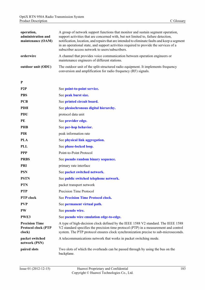
operation,administration andmaintenance (OAM)
A group of network support functions that monitor and sustain segment operation,support activities that are concerned with, but not limited to, failure detection,notification, location, and repairs that are intended to eliminate faults and keep a segmentin an operational state, and support activities required to provide the services of asubscriber access network to users/subscribers.
orderwire A channel that provides voice communication between operation engineers ormaintenance engineers of different stations.
outdoor unit (ODU) The outdoor unit of the split-structured radio equipment. It implements frequencyconversion and amplification for radio frequency (RF) signals.
P
P2P See point-to-point service.
PBS See peak burst size.
PCB See printed circuit board.
PDH See plesiochronous digital hierarchy.
PDU protocol data unit
PE See provider edge.
PHB See per-hop behavior.
PIR peak information rate
PLA See physical link aggregation.
PLL See phase-locked loop.
PPP Point-to-Point Protocol
PRBS See pseudo random binary sequence.
PRI primary rate interface
PSN See packet switched network.
PSTN See public switched telephone network.
PTN packet transport network
PTP Precision Time Protocol
PTP clock See Precision Time Protocol clock.
PVP See permanent virtual path.
PW See pseudo wire.
PWE3 See pseudo wire emulation edge-to-edge.
Precision TimeProtocol clock (PTPclock)
A type of high-decision clock defined by the IEEE 1588 V2 standard. The IEEE 1588V2 standard specifies the precision time protocol (PTP) in a measurement and controlsystem. The PTP protocol ensures clock synchronization precise to sub-microseconds.
packet switchednetwork (PSN)
A telecommunications network that works in packet switching mode.
paired slots Two slots of which the overheads can be passed through by using the bus on thebackplane.
OptiX RTN 950A Radio Transmission SystemProduct Description C Glossary
Issue 01 (2012-12-15) Huawei Proprietary and ConfidentialCopyright © Huawei Technologies Co., Ltd.
183

peak burst size (PBS) A parameter that is used to define the capacity of token bucket P, that is, the maximumburst IP packet size when the information is transferred at the peak information rate. Thisparameter must be larger than 0. It is recommended that PBS should be not less than themaximum length of the IP packet that might be forwarded. See also CIR, CBS, and PIR.
per-hop behavior(PHB)
IETF Diff-Serv workgroup defines forwarding behaviors of network nodes as per-hopbehaviors (PHB), such as, traffic scheduling and policing. A device in the network shouldselect the proper PHB behaviors, based on the value of DSCP. At present, the IETFdefines four types of PHB. They are class selector (CS), expedited forwarding (EF),assured forwarding (AF), and best-effort (BE).
permanent virtual path(PVP)
Virtual path that consists of PVCs.
phase-locked loop(PLL)
A circuit that consists essentially of a phase detector which compares the frequency ofa voltage-controlled oscillator with that of an incoming carrier signal or reference-frequency generator; the output of the phase detector, after passing through a loop filter,is fed back to the voltage-controlled oscillator to keep it exactly in phase with theincoming or reference frequency.
physical linkaggregation (PLA)
Being a technology providing load balancing based on physical layer bandwidths,physical link aggregation (PLA) combines Ethernet transmission paths in severalIntegrated IP radio links into a logical Ethernet link for higher Ethernet bandwidth andEthernet transmission reliability.
plesiochronous digitalhierarchy (PDH)
A multiplexing scheme of bit stuffing and byte interleaving. It multiplexes the minimumrate 64 kit/s into the 2 Mbit/s, 34 Mbit/s, 140 Mbit/s, and 565 Mbit/s rates.
point-to-point service(P2P)
A service between two terminal users. In P2P services, senders and recipients areterminal users.
polarization A kind of electromagnetic wave, the direction of whose electric field vector is fixed orrotates regularly. Specifically, if the electric field vector of the electromagnetic wave isperpendicular to the plane of horizon, this electromagnetic wave is called verticallypolarized wave; if the electric field vector of the electromagnetic wave is parallel to theplane of horizon, this electromagnetic wave is called horizontal polarized wave; if thetip of the electric field vector, at a fixed point in space, describes a circle, thiselectromagnetic wave is called circularly polarized wave.
printed circuit board(PCB)
A board used to mechanically support and electrically connect electronic componentsusing conductive pathways, tracks, or traces, etched from copper sheets laminated ontoa non-conductive substrate.
provider edge (PE) A device that is located in the backbone network of the MPLS VPN structure. A PE isresponsible for managing VPN users, establishing LSPs between PEs, and exchangingrouting information between sites of the same VPN. A PE performs the mapping andforwarding of packets between the private network and the public channel. A PE can bea UPE, an SPE, or an NPE.
pseudo random binarysequence (PRBS)
A sequence that is random in a sense that the value of an element is independent of thevalues of any of the other elements, similar to real random sequences.
pseudo wire (PW) An emulated connection between two PEs for transmitting frames. The PW is establishedand maintained by PEs through signaling protocols. The status information of a PW ismaintained by the two end PEs of a PW.
OptiX RTN 950A Radio Transmission SystemProduct Description C Glossary
Issue 01 (2012-12-15) Huawei Proprietary and ConfidentialCopyright © Huawei Technologies Co., Ltd.
184

pseudo wire emulationedge-to-edge (PWE3)
An end-to-end Layer 2 transmission technology. It emulates the essential attributes of atelecommunication service such as ATM, FR or Ethernet in a packet switched network(PSN). PWE3 also emulates the essential attributes of low speed time divisionmultiplexing (TDM) circuit and SONET/SDH. The simulation approximates to the realsituation.
public switchedtelephone network(PSTN)
A telecommunications network established to perform telephone services for the publicsubscribers. Sometimes it is called POTS.
Q
QAM See quadrature amplitude modulation.
QPSK See quadrature phase shift keying.
QinQ A layer 2 tunnel protocol based on IEEE 802.1Q encapsulation. It add a public VLANtag to a frame with a private VLAN tag to allow the frame with double VLAN tags tobe transmitted over the service provider's backbone network based on the public VLANtag. This provides a layer 2 VPN tunnel for customers and enables transparenttransmission of packets over private VLANs.
QoS See quality of service.
quadrature amplitudemodulation (QAM)
Both an analog and a digital modulation scheme. It conveys two analog message signals,or two digital bit streams, by changing (modulating) the amplitudes of two carrier waves,using the amplitude-shift keying (ASK) digital modulation scheme or amplitudemodulation (AM) analog modulation scheme. These two waves, usually sinusoids, areout of phase with each other by 90° and are thus called quadrature carriers or quadraturecomponents — hence the name of the scheme.
quadrature phase shiftkeying (QPSK)
A modulation method of data transmission through the conversion or modulation andthe phase determination of the reference signals (carrier). It is also called the fourth periodor 4-phase PSK or 4-PSK. QPSK uses four dots in the star diagram. The four dots areevenly distributed on a circle. On these phases, each QPSK character can perform two-bit coding and display the codes in Gray code on graph with the minimum BER.
quality of service (QoS) A commonly-used performance indicator of a telecommunication system or channel.Depending on the specific system and service, it may relate to jitter, delay, packet lossratio, bit error ratio, and signal-to-noise ratio. It functions to measure the quality of thetransmission system and the effectiveness of the services, as well as the capability of aservice provider to meet the demands of users.
R
RADIUS See Remote Authentication Dial-In User Service.
RADIUS accounting An accounting mode in which the BRAS sends the accounting packets to the RADIUSserver. Then the RADIUS server performs accounting.
RDI remote defect indication
RED See random early detection.
REI remote error indication
RF See radio frequency.
RFC See Request For Comments.
OptiX RTN 950A Radio Transmission SystemProduct Description C Glossary
Issue 01 (2012-12-15) Huawei Proprietary and ConfidentialCopyright © Huawei Technologies Co., Ltd.
185

RMEP remote maintenance association end point
RMON remote network monitoring
RNC See radio network controller.
RSL See received signal level.
RSSI See received signal strength indicator.
RSTP See Rapid Spanning Tree Protocol.
RSVP See Resource Reservation Protocol.
RTN radio transmission node
RTSP Real-Time Streaming Protocol
Rapid Spanning TreeProtocol (RSTP)
An evolution of the Spanning Tree Protocol, providing for faster spanning treeconvergence after a topology change. The RSTP protocol is backward compatible withthe STP protocol.
Remote AuthenticationDial-In User Service(RADIUS)
A security service that authenticates and authorizes dial-up users and is a centralizedaccess control mechanism. RADIUS uses the User Datagram Protocol (UDP) as itstransmission protocol to ensure real-time quality. RADIUS also supports theretransmission and multi-server mechanisms to ensure good reliability.
Request For Comments(RFC)
A document in which a standard, a protocol, or other information pertaining to theoperation of the Internet is published. The RFC is actually issued, under the control ofthe IAB, after discussion and serves as the standard. RFCs can be obtained from sourcessuch as InterNIC.
Resource ReservationProtocol (RSVP)
A network control protocol like Internet Control Message Protocol (ICMP) and designedfor Integrated Service and used to reserve resources on every node along a path. RSVPoperates on the transport layer; however, RSVP does not transport application data.
RoHS restriction of the use of certain hazardous substances
radio frequency (RF) A type of electric current in the wireless network using AC antennas to create anelectromagnetic field. It is the abbreviation of high-frequency AC electromagnetic wave.The AC with the frequency lower than 1 kHz is called low-frequency current. The ACwith frequency higher than 10 kHz is called high-frequency current. RF can be classifiedinto such high-frequency current.
radio networkcontroller (RNC)
A piece of equipment in the RNS which is in charge of controlling the use and the integrityof the radio resources.
random early detection(RED)
A packet loss algorithm used in congestion avoidance. It discards the packet accordingto the specified higher limit and lower limit of a queue so that global TCP synchronizationresulting from traditional tail drop can be prevented.
real-time variable bitrate (rt-VBR)
A parameter intended for real-time applications, such as compressed voice over IP(VoIP) and video conferencing. The rt-VBR is characterized by a peak cell rate (PCR),sustained cell rate (SCR), and maximum burst size (MBS). You can expect the sourcedevice to transmit in bursts and at a rate that varies with time.
received signal level(RSL)
The signal level at a receiver input terminal.
received signal strengthindicator (RSSI)
The received wide band power, including thermal noise and noise generated in thereceiver, within the bandwidth defined by the receiver pulse shaping filter, for TDDwithin a specified timeslot. The reference point for the measurement shall be the antenna
OptiX RTN 950A Radio Transmission SystemProduct Description C Glossary
Issue 01 (2012-12-15) Huawei Proprietary and ConfidentialCopyright © Huawei Technologies Co., Ltd.
186

receiver sensitivity The minimum acceptable value of average received power at point R to achieve a 1 x10-12 BER (The FEC is open).
regeneration The process of receiving and reconstructing a digital signal so that the amplitudes,waveforms and timing of its signal elements are constrained within specified limits.
route The path that network traffic takes from its source to its destination. In a TCP/IP network,each IP packet is routed independently. Routes can change dynamically.
router A device on the network layer that selects routes in the network. The router selects theoptimal route according to the destination address of the received packet through anetwork and forwards the packet to the next router. The last router is responsible forsending the packet to the destination host. Can be used to connect a LAN to a LAN, aWAN to a WAN, or a LAN to the Internet.
rt-VBR See real-time variable bit rate.
S
SAI service area identifier
SAToP Structure-Agnostic Time Division Multiplexing over Packet
SCSI small computer system interface
SD See space diversity.
SDH See synchronous digital hierarchy.
SEC security screening
SES severely errored second
SETS SDH equipment timing source
SF See signal fail.
SFP small form-factor pluggable
SLA See service level agreement.
SNCP subnetwork connection protection
SNMP See Simple Network Management Protocol.
SNR See signal-to-noise ratio.
SRN serial number
SSL See Secure Sockets Layer.
SSM See Synchronization Status Message.
STM See synchronous transport module.
STM-1 See Synchronous Transport Module level 1.
STM-4 Synchronous Transport Module level 4
STM-N Synchronous Transport Module level N
STP Spanning Tree Protocol
Secure Sockets Layer(SSL)
A security protocol that works at a socket level. This layer exists between the TCP layerand the application layer to encrypt/decode data and authenticate concerned entities.
OptiX RTN 950A Radio Transmission SystemProduct Description C Glossary
Issue 01 (2012-12-15) Huawei Proprietary and ConfidentialCopyright © Huawei Technologies Co., Ltd.
187

Simple NetworkManagement Protocol(SNMP)
A network management protocol of TCP/IP. It enables remote users to view and modifythe management information of a network element. This protocol ensures thetransmission of management information between any two points. The pollingmechanism is adopted to provide basic function sets. According to SNMP, agents, whichcan be hardware as well as software, can monitor the activities of various devices on thenetwork and report these activities to the network console workstation. Controlinformation about each device is maintained by a management information block.
Synchronization StatusMessage (SSM)
A message that carries quality levels of timing signals on a synchronous timing link.Nodes on an SDH network and a synchronization network acquire upstream clockinformation through this message. Then the nodes can perform proper operations on theirclocks, such as tracing, switching, or converting to holdoff, and forward thesynchronization information to downstream nodes.
SynchronousTransport Module level1 (STM-1)
Synchronous transfer mode at 155 Mbit/s.
service level agreement(SLA)
A service agreement between a customer and a service provider. SLA specifies theservice level for a customer. The customer can be a user organization (source domain)or another differentiated services domain (upstream domain). An SLA may includetraffic conditioning rules which constitute a traffic conditioning agreement as a wholeor partially.
signal fail (SF) A signal indicating that associated data has failed in the sense that a near-end defectcondition (non-degrade defect) is active.
signal-to-noise ratio(SNR)
The ratio of the amplitude of the desired signal to the amplitude of noise signals at agiven point in time. SNR is expressed as 10 times the logarithm of the power ratio andis usually expressed in dB (Decibel).
single-ended switching A protection operation method that takes switching action only at the affected end of theprotected entity (for example, trail, subnetwork connection), in the case of aunidirectional failure.
single-polarizedantenna
An antenna intended to radiate or receive radio waves with only one specifiedpolarization.
space diversity (SD) A diversity scheme that enables two or more antennas separated by a specific distanceto transmit/receive the same signal and selection is then performed between the twosignals to ease the impact of fading. Currently, only receive SD is used.
subnet mask The technique used by the IP protocol to determine which network segment packets aredestined for. The subnet mask is a binary pattern that is stored in the client machine,server or router matches with the IP address.
synchronous digitalhierarchy (SDH)
A transmission scheme that follows ITU-T G.707, G.708, and G.709. It defines thetransmission features of digital signals such as frame structure, multiplexing mode,transmission rate level, and interface code. SDH is an important part of ISDN and B-ISDN. It interleaves the bytes of low-speed signals to multiplex the signals to high-speedcounterparts, and the line coding of scrambling is used only for signals. SDH is suitablefor the fiber communication system with high speed and a large capacity since it usessynchronous multiplexing and flexible mapping structure.
OptiX RTN 950A Radio Transmission SystemProduct Description C Glossary
Issue 01 (2012-12-15) Huawei Proprietary and ConfidentialCopyright © Huawei Technologies Co., Ltd.
188

synchronous transportmodule (STM)
An information structure used to support section layer connections in the SDH. It consistsof information payload and Section Overhead (SOH) information fields organized in ablock frame structure which repeats every 125. The information is suitably conditionedfor serial transmission on the selected media at a rate which is synchronized to thenetwork. A basic STM is defined at 155 520 kbit/s. This is termed STM-1. Highercapacity STMs are formed at rates equivalent to N times this basic rate. STM capacitiesfor N = 4, N = 16 and N = 64 are defined; higher values are under consideration.
T
T1 A North American standard for high-speed data transmission at 1.544Mbps. It provides24 x 64 kbit/s channels.
TCI tag control information
TCP See Transmission Control Protocol.
TCP/IP Transmission Control Protocol/Internet Protocol
TD-SCDMA See Time Division-Synchronous Code Division Multiple Access.
TDD time division duplex
TDM See time division multiplexing.
TDMA See Time Division Multiple Access.
TE See traffic engineering.
TEDB See traffic engineering database.
TIM trace identifier mismatch
TMN See telecommunications management network.
TOS test operation system
TTL See time to live.
TUG tributary unit group
Telnet A standard terminal emulation protocol in the TCP/IP protocol stack. Telnet allows usersto log in to remote systems and use resources as if they were connected to a local system.Telnet is defined in RFC 854.
Time Division MultipleAccess (TDMA)
An approach used for allocating a single channel among many users, by dividing thechannel into different timeslots during which each user has access to the medium.
Time Division-Synchronous CodeDivision MultipleAccess (TD-SCDMA)
A 3G mobile communications standard found in UMTS mobile telecommunicationsnetworks in China as an alternative to W-CDMA. TD-SCDMA integrates technologiesof CDMA, TDMA, and FDMA, and makes use of technologies including intelligentantenna, joint detection, low chip rate (LCR), and adaptive power control. With theflexibility of service processing, a TD-SCDMA network can connect to other networksthrough the RNC.
Transmission ControlProtocol (TCP)
The protocol within TCP/IP that governs the breakup of data messages into packets tobe sent using Internet Protocol (IP), and the reassembly and verification of the completemessages from packets received by IP. A connection-oriented, reliable protocol (reliablein the sense of ensuring error-free delivery), TCP corresponds to the transport layer inthe ISO/OSI reference model.
OptiX RTN 950A Radio Transmission SystemProduct Description C Glossary
Issue 01 (2012-12-15) Huawei Proprietary and ConfidentialCopyright © Huawei Technologies Co., Ltd.
189

tail drop A congestion management mechanism, in which packets arrive later are discarded whenthe queue is full. This policy of discarding packets may result in network-widesynchronization due to the TCP slow startup mechanism.
tangent ring A concept borrowed from geometry. Two tangent rings have a common node betweenthem. The common node often leads to single-point failures.
telecommunicationsmanagement network(TMN)
A protocol model defined by ITU-T for managing open systems in a communicationsnetwork. An architecture for management, including planning, provisioning, installation,maintenance, operation and administration of telecommunications equipment, networksand services.
time divisionmultiplexing (TDM)
A multiplexing technology. TDM divides the sampling cycle of a channel into time slots(TSn, n=0, 1, 2, 3…), and the sampling value codes of multiple signals engross time slotsin a certain order, forming multiple multiplexing digital signals to be transmitted overone channel.
time to live (TTL) A technique used in best-effort delivery systems to prevent packets that loop endlessly.The TTL is set by the sender to the maximum time the packet is allowed to be in thenetwork. Each router in the network decrements the TTL value when the packet arrives,and discards any packet if the TTL counter reaches zero.
trTCM See two rate three color marker.
traffic engineering (TE) A technology that is used to dynamically monitor the traffic of the network and the loadof the network elements, to adjust in real time the parameters such as traffic managementparameters, route parameters and resource restriction parameters, and to optimize theutilization of network resources. The purpose is to prevent the congestion caused byunbalanced loads.
traffic engineeringdatabase (TEDB)
A type of database that every router generates after collecting the information about TEof every links in its area. TEDB is the base of forming the dynamic TE path in the MPLSTE network.
tributary loopback A fault can be located for each service path by performing loopback to each path of thetributary board. There are three kinds of loopback modes: no loopback, outloop, andinloop.
tunnel A channel on the packet switching network that transmits service traffic between PEs.In VPN, a tunnel is an information transmission channel between two entities. The tunnelensures secure and transparent transmission of VPN information. In most cases, a tunnelis an MPLS tunnel.
two rate three colormarker (trTCM)
An algorithm that meters an IP packet stream and marks its packets based on two rates,Peak Information Rate (PIR) and Committed Information Rate (CIR), and theirassociated burst sizes to be either green, yellow, or red. A packet is marked red if itexceeds the PIR. Otherwise it is marked either yellow or green depending on whether itexceeds or does not exceed the CIR.
U
UART universal asynchronous receiver/transmitter
UAS unavailable second
UBR unspecified bit rate
UBR+ Unspecified Bit Rate Plus
UDP See User Datagram Protocol.
OptiX RTN 950A Radio Transmission SystemProduct Description C Glossary
Issue 01 (2012-12-15) Huawei Proprietary and ConfidentialCopyright © Huawei Technologies Co., Ltd.
190

UI user interface
UNI See user-to-network interface.
UPC See usage parameter control.
User DatagramProtocol (UDP)
A TCP/IP standard protocol that allows an application program on one device to send adatagram to an application program on another. User Datagram Protocol (UDP) uses IPto deliver datagram. UDP provides application programs with the unreliableconnectionless packet delivery service. There is a possibility that UDP messages will belost, duplicated, delayed, or delivered out of order. The destination device does notconfirm whether a data packet is received.
unicast The process of sending data from a source to a single recipient.
usage parametercontrol (UPC)
During communications, UPC is implemented to monitor the actual traffic on each virtualcircuit that is input to the network. Once the specified parameter is exceeded, measureswill be taken to control. NPC is similar to UPC in function. The difference is that theincoming traffic monitoring function is divided into UPC and NPC according to theirpositions. UPC locates at the user/network interface, while NPC at the network interface.
user-to-networkinterface (UNI)
The interface between user equipment and private or public network equipment (forexample, ATM switches).
V
V-NNI virtual network-network interface
V-UNI See virtual user-network interface.
VB virtual bridge
VBR See variable bit rate.
VC See virtual container.
VCC See virtual channel connection.
VCCV virtual circuit connectivity verification
VCG See virtual concatenation group.
VCI virtual channel identifier
VCTRUNK A virtual concatenation group applied in data service mapping, also called the internalport of a data service processing board.
VLAN virtual local area network
VPI See virtual path identifier.
VPLS virtual private LAN segment
VPN virtual private network
VSWR voltage standing wave ratio
VoIP See voice over IP.
variable bit rate (VBR) One of the traffic classes used by ATM (Asynchronous Transfer Mode). Unlike apermanent CBR (Constant Bit Rate) channel, a VBR data stream varies in bandwidthand is better suited to non real time transfers than to real-time streams such as voice calls.
OptiX RTN 950A Radio Transmission SystemProduct Description C Glossary
Issue 01 (2012-12-15) Huawei Proprietary and ConfidentialCopyright © Huawei Technologies Co., Ltd.
191

virtual channelconnection (VCC)
A VC logical trail that carries data between two end points in an ATM network. A point-to-multipoint VCC is a set of ATM virtual connections between two or multiple endpoints.
virtual circuit A channel or circuit established between two points on a data communications networkwith packet switching. Virtual circuits can be permanent virtual circuits (PVCs) orswitched virtual circuits (SVCs) .
virtual concatenationgroup (VCG)
A group of co-located member trail termination functions that are connected to the samevirtual concatenation link
virtual container (VC) The information structure used to support path layer connections in the SDH. It consistsof information payload and path overhead (POH) information fields organized in a blockframe structure which repeats every 125 or 500 μs.
virtual path identifier(VPI)
The field in the Asynchronous Transfer Mode (ATM) cell header that identifies to whichvirtual path the cell belongs.
virtual user-networkinterface (V-UNI)
A virtual user-network interface, works as an action point to perform serviceclassification and traffic control in HQoS.
voice over IP (VoIP) An IP telephony term for a set of facilities used to manage the delivery of voiceinformation over the Internet. VoIP involves sending voice information in a digital formin discrete packets rather than by using the traditional circuit-committed protocols of thepublic switched telephone network (PSTN).
W
WAN See wide area network.
WCDMA See Wideband Code Division Multiple Access.
WDM wavelength division multiplexing
WEEE waste electrical and electronic equipment
WFQ See weighted fair queuing.
WRED See weighted random early detection.
WRR weighted round robin
WTR See wait to restore.
Web LCT The local maintenance terminal of a transport network, which is located at the NEmanagement layer of the transport network.
Wi-Fi See Wireless Fidelity.
Wideband CodeDivision MultipleAccess (WCDMA)
A standard defined by the ITU-T for the third-generation wireless technology derivedfrom the Code Division Multiple Access (CDMA) technology.
Wireless Fidelity (Wi-Fi)
A short-distant wireless transmission technology. It enables wireless access to theInternet within a range of hundreds of feet wide.
wait to restore (WTR) The number of minutes to wait before services are switched back to the working line.
weighted fair queuing(WFQ)
A fair queue scheduling algorithm based on bandwidth allocation weights. Thisscheduling algorithm allocates the total bandwidth of an interface to queues, accordingto their weights and schedules the queues cyclically. In this manner, packets of all priorityqueues can be scheduled.
OptiX RTN 950A Radio Transmission SystemProduct Description C Glossary
Issue 01 (2012-12-15) Huawei Proprietary and ConfidentialCopyright © Huawei Technologies Co., Ltd.
192

weighted random earlydetection (WRED)
A packet loss algorithm used for congestion avoidance. It can prevent the global TCPsynchronization caused by traditional tail-drop. WRED is favorable for the high-prioritypacket when calculating the packet loss ratio.
wide area network(WAN)
A network composed of computers which are far away from each other which arephysically connected through specific protocols. WAN covers a broad area, such as aprovince, a state or even a country.
winding pipe A tool for fiber routing, which acts as the corrugated pipe.
X
XPIC See cross polarization interference cancellation.
OptiX RTN 950A Radio Transmission SystemProduct Description C Glossary
Issue 01 (2012-12-15) Huawei Proprietary and ConfidentialCopyright © Huawei Technologies Co., Ltd.
193