Embed Size (px)
DESCRIPTION
RTML Design and Rational for ILC Nikolay Solyak Fermilab. CLIC 08 workshop, CERN, Oct. 14-17, 2008. Outline RTML Optic Design (RDR) Technical Systems Emittance control Post-RDR changes. RTML Functions. Transport Beam from DR to ML Match Geometry/Optics Collimate Halo - PowerPoint PPT Presentation
Citation preview

N.Solyak, RTML CLIC 08, CERN, Oct. 14-17, 2008 1
RTML Design
and
Rational for ILC
Nikolay Solyak
Fermilab
CLIC 08 workshop, CERN, Oct. 14-17, 2008

N.Solyak, RTML CLIC 08, CERN, Oct. 14-17, 2008 2
Outline
• RTML Optic Design (RDR)
• Technical Systems• Emittance control• Post-RDR changes
N.Solyak, RTML CLIC 08, CERN, Oct. 14-17, 2008 3
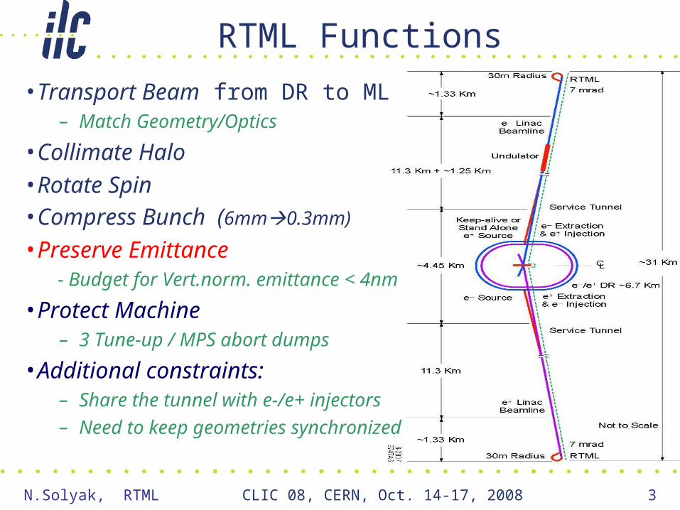
RTML Functions
• Transport Beam from DR to ML – Match Geometry/Optics
• Collimate Halo
• Rotate Spin • Compress Bunch (6mm0.3mm)
• Preserve Emittance - Budget for Vert.norm. emittance < 4nm
• Protect Machine– 3 Tune-up / MPS abort dumps
• Additional constraints:– Share the tunnel with e-/e+ injectors – Need to keep geometries
synchronized

N.Solyak, RTML CLIC 08, CERN, Oct. 14-17, 2008 4
RTML Schematic (RDR)
Note: e- and e+ RTMLs have minor differences in Return line (undulator in e- linac side) and Escalator (DR’s at different elevations); they are otherwise identical.
BDS
Separate tunnel1254 m
Areas, where tunnel length saving is essential
Same curved tunnel (RTML/ML)

N.Solyak, RTML CLIC 08, CERN, Oct. 14-17, 2008 5
Optics Design (RDR)
DRX connection
Vertical plane
Horizontal plane
Horizontal plane
• Horizontal Arc out of DR ~km straight
– In injector tunnel• “Escalator” ~0.6 km vertical dogleg
down to linac tunnel• Return line, weak FODO lattice
– In linac tunnel– Vertically curved
• Vertical and horizontal doglegs• Turnaround• 8° arc in spin rotators• BCs are net straight
DR-RTML hand-off point defined extraction point where η,η’ 0RTML mostly defined by need to follow LTR geometry Stay in same tunnelDesign is OK at conceptual level
DRX+ arc

N.Solyak, RTML CLIC 08, CERN, Oct. 14-17, 2008 6
DR connection (RDR)
Post RDR modifications
• No elevation for the service tunnel
• ML and RTML tunnels merge in horizontal plane
• New DR design
• Shorter tunnel shared with KAS ?
• Both sides need 5GeV SC linacs (e+/e- sources);
• e+ side also needs KAS and e+ transfer line from undulator
N.Solyak, RTML CLIC 08, CERN, Oct. 14-17, 2008 7
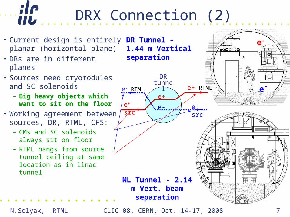
DRX Connection (2)
• Current design is entirely planar (horizontal plane)
• DRs are in different planes• Sources need cryomodules
and SC solenoids– Big heavy objects which
want to sit on the floor
• Working agreement between sources, DR, RTML, CFS:– CMs and SC solenoids
always sit on floor– RTML hangs from source
tunnel ceiling at same location as in linac tunnel
DR Tunnel – 1.44 m Vertical separation
ML Tunnel - 2.14 m Vert. beam separation
e+
e-
DR tunnel
e-
e+
e- src
e+ RTMLe- RTML
e+ src

N.Solyak, RTML CLIC 08, CERN, Oct. 14-17, 2008 8
“Getaway” Straight (or “DR Stretch”)
Beam collimationEnergy collimation
Decoupling: Skew correctorsDiagnostics: Emittance meas
• About 1.1 km long• Has two parts
– “Low-beta” region with decoupling and emittance measurement
– “High-beta” region with collimation system
• Includes PPS stoppers– For segmentation
• Good conceptual design– Need to match exact
required system lengths– Beta match between low-
and high-beta optics not great
• Length of “Getaway’’ can be minimized to ~ 500m
N.Solyak, RTML CLIC 08, CERN, Oct. 14-17, 2008 9
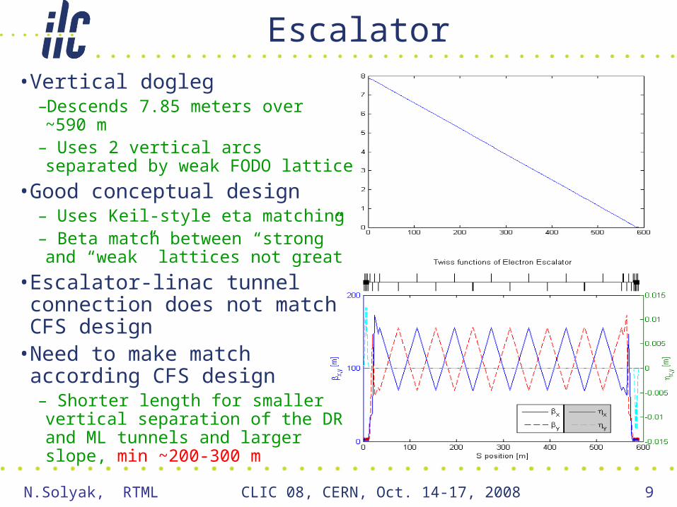
Escalator
• Vertical dogleg–Descends 7.85 meters over ~590 m– Uses 2 vertical arcs separated by weak FODO lattice
• Good conceptual design– Uses Keil-style eta matching– Beta match between “strong” and “weak” lattices not great
• Escalator-linac tunnel connection does not match CFS design
• Need to make match according CFS design– Shorter length for smaller vertical separation of the DR and ML tunnels and larger slope, min ~200-300 m
N.Solyak, RTML CLIC 08, CERN, Oct. 14-17, 2008 10
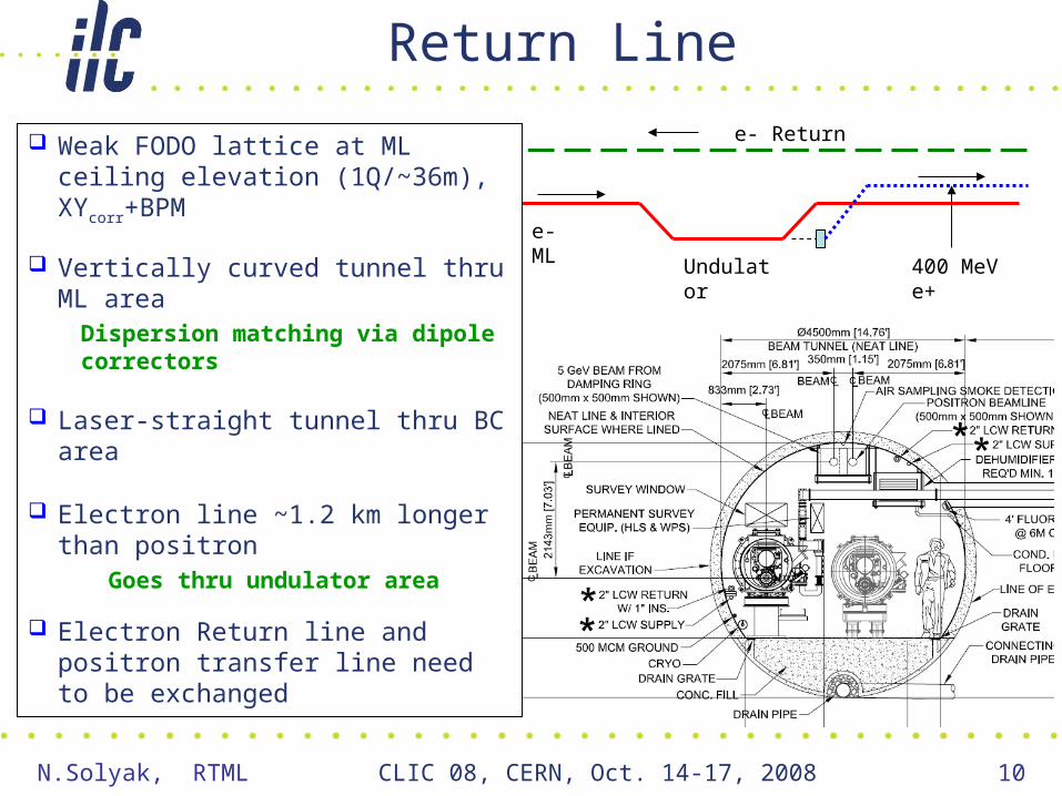
Return Line
e- ML
Undulator 400 MeV e+
e- Return Weak FODO lattice at ML ceiling elevation (1Q/~36m), XYcorr+BPM
Vertically curved tunnel thru ML area
Dispersion matching via dipole correctors
Laser-straight tunnel thru BC area
Electron line ~1.2 km longer than positron
Goes thru undulator area
Electron Return line and positron transfer line need to be exchanged

N.Solyak, RTML CLIC 08, CERN, Oct. 14-17, 2008 11
Turnaround (D & B)
• Actually does 3 jobs– Turns the beam around
• Note: need to bend away from service tunnel
– Brings beam down from ceiling to linac elevation (near floor)
• Vertical dogleg
– Adjusts x position to meet linac line
• Horizontal dogleg
• Order: H dogleg, V dogleg, turnaround
• Risk - high packing area ~90% magnets. Tunnel length is already min.
Spin Rotator
Vertical
Horizontal

N.Solyak, RTML CLIC 08, CERN, Oct. 14-17, 2008 12
Spin Rotation
• Design based on Emma’s from NLC ZDR. Arbitrary spin orientation in IP
– 2 solenoids with Emma rotator between them
• Rotate spin 90° in xy plane while cancelling coupling
– 8° arc
• Rotate spin 90° in xz plane
– Another 2 solenoids + Emma rotator
• Basic design seems sound– Very small loss in
polarization from vertical bending in linac tunnel

N.Solyak, RTML CLIC 08, CERN, Oct. 14-17, 2008 13
ILC Baseline Bunch Compressor• Longitudinal emittance out of DR:
– 6mm (or 9 mm) RMS length– 0.15% RMS energy spread
• Want to go down to 0.2-0.3 mm• Need some adjustability• Use 2-stage BC to limit max energy
spread– 1st: Compress to 1 mm at 5 GeV– 2nd: Accelerate to 15 GeV and Compress to final bunch length
• Both stages use 6-cell lattice with quads and bends to achieve momentum compaction (wiggler)
– Magnet aperture ~ 40cm
• Total Length ~1100 m (incl. matching and beam extraction lines)
• Minimum design is possible if assume compression 60.3 mm only
• Shorter 2-stage BC• Or short single-stage BC• Cheaper magnets
RF system• BC1: 3 CMs with quads (+spare kly)• BC2: 14 RFunits (3CM’s each)+1spare • Total 48 CM’s per side
One wiggler cell
RF1 RF2Wiggler 1
Wiggler 2

N.Solyak, RTML CLIC 08, CERN, Oct. 14-17, 2008 14
BC: Phase and amplitude stability
The required tolerances for amplitude and phase stability in BC are very tough:- Phase stability tolerance: 0.25°/0.16° – long/short bunch- Amplitude stability tolerance: 0.5%/0.35% rms – long/short bunch
Bunch compressor RF cavities operate close to zero-crossing:- Phase 105° off-crest (BC1)- Phase 27.6° off-crest (BC2)
The gradient in the RF system ~30 MeV/m. Zero crossing regime – complication for LLRF system.
Study of the phase and amplitude stability of the RF system @ FLASH (2009).

N.Solyak, RTML CLIC 08, CERN, Oct. 14-17, 2008 15
Alternative Bunch Compressor• An alternate bunch compressor design exists (~700m)
– 6-cell wigglers (~150 m each, 102 bend magnets) replaced by chicanes (~40 m each, 4 bend magnets)
– Advantages: Shorter, Simpler, Cheaper (less magnets)– Disadvantages: Big x offset from straight line (~1.8 m)
» Doesn’t have natural locations for dispersion tuning quads– Length Saving: ~ (200 ÷ 300 m)
Initial Energy Spread [%] 0.15
Initial Bunch Length [mm]Initial Emittance [m]
6.08 / 0.02
BC1 Voltage [MV] 348BC1 Phase [°] -114BC1 R56 [mm] -474.2End BC1 Bunch Length [mm] 1.1End BC1 Energy [GeV] 4.86End BC1 Energy Spread [%] 1.1BC2 Voltage [MV] 11,800BC2 Phase [°] -45BC2 R56 [mm] -50.8
End BC2 Bunch Length [mm]End BC2 Emittance [m]
0.158.3 / 0.02
End BC2 Energy [GeV] 13.26End BC2 Energy Spread [%] 2.2

N.Solyak, RTML CLIC 08, CERN, Oct. 14-17, 2008 16
Pulsed Extraction Lines• 3 Extraction Lines in each RTML side for emergency beam
abort (MPS) and tune-up– EL1 - after DR exit, diagnostics, global correction – 5 GeV, E = 0.15%
• Keep DRs running @ full power during access• Keep DRs and extraction tuned during access• MPS abort (~100ns)
– ELBC1 - after BC1 – 5 or 4.88 GeV, E = 0.15% and 2.5%
• Tune up BC1 without beam in BC2 • MPS abort
– ELBC2 - after BC2 – 15 GeV, E = 0.15% and 1.8%
• Tune up BC2 without beam in linac• MPS abort
• All have 220 kW beam handling power– Full power for DRX, BC1– 1/3 power for BC2

N.Solyak, RTML CLIC 08, CERN, Oct. 14-17, 2008 17
Note: Schematic only, not to scale!
Main beamline (DR-to-IP)
Kicker and septum
Beamline to tune-up dump
Beam dump: 220kW @15GeV + local shielding
>2 m earth shielding
<~100W Beam loss this area
1 km
20-cm-thick Pb
3 burn through monitors Access OK
Accelerator Tunnel
Service Tunnel
5 m earth shielding
Access OK: 0.14 mSv/hr w/o local dump shielding; 0.025 mSv/hr with local dump shielding
5 m
~ 30
- 40
m
Extraction Line Layout

N.Solyak, RTML CLIC 08, CERN, Oct. 14-17, 2008 18
EL1 design

N.Solyak, RTML CLIC 08, CERN, Oct. 14-17, 2008 19
ELBC1 Line Design•Separation of the two lines at CM
location (14m down) - 2m; •Separation of the dump and the ML ~5
m;•DBA to decouple dispersion and beam
size issues•Beam size on the dump window ~15
mm2
• Length = 20.7 m 0.15% energy spread
2.5% energy spread
Defocus
• Two collimators to protect downstream triplet
•intercepts 3.9 kW/train and 18.8 kW/train
septum match DBA

N.Solyak, RTML CLIC 08, CERN, Oct. 14-17, 2008 20
ELBC2 Design• ELBC2 similar to ELBC1, but ~ 5m longer (extra bending cell)
• 6 septum+6 bends+12 quads, • two collimators: 5.2 kW (protect quads) and 14.1 kW (dump window)
0.15% (green) and 1.8% (red) energy spread
2 coll 1 coll No coll
Final quads
1T 45mm
1T 45mm
2T80mm
Collimat
5.2 kW 14.1kW
5.2kW
No coll
Dump window
12.5 cm
30 cm
100 cm
Defocus

N.Solyak, RTML CLIC 08, CERN, Oct. 14-17, 2008 21
Halo and Energy Collimation• ILC specification:
– Needs to limit halo at end linac to ~10-5 of total beam power
• Halo Collimation after DR– BDS specification as requirement
• Halo power ~ 220 W• Provide machine protection
– Collimators stop out-of-control beam from DR– Need to keep out-of-control beam from frying collimators, too!
• Energy collimators after betatron collimation system– Scattered particles
– Off-momentum particles / bunches from DR
• Additional energy collimators– In BC1 wiggler
– In BC2 wiggler
• Collimators in Extraction Lines ELBC1 and ELBC2• Need to understand machine protection issues for these collimators

N.Solyak, RTML CLIC 08, CERN, Oct. 14-17, 2008 22
Technical Systems
• Magnets and power supplies (~4600 Magnets)– SC quads/correctors/solenoids (36/54/8),– RT quad, correctors, septa– Pulsed magnets, kickers, bends, FB/FF correctors
• Vacuum system– Current baseline
• 2 cm OD stainless chambers– Exceptions: BC bends, extraction lines, CMs
• 20 nTorr in long line from DR to turnaround– Passivated to reduce outgassing rate
• 100 nTorr in balance of system (turnaround to linac)
• Dumps and Collimators– 3 dumps per side with 220 kW capacity– Betatron and energy spoilers / absorbers with ~200 W
capacity (20 adjustable aperture (5W) +28 fixed-aperture collimators)/side
– Few collimators with ~10 kW capacity

N.Solyak, RTML CLIC 08, CERN, Oct. 14-17, 2008 23
Six ~220kW Aluminum Ball Dumps
Cost ($1M each) is dominated by:– 3-loop radioactive water
processing system– The CFS infrastructure,
shielding, etc.Similar dumps in use at SLAC
50cm Diameter x 2m long Aluminum Ball Dump with
Local Shielding
RW
50kW 3-loop 2006 Rad Water Cooling for ISIS Neutron Spallation Targets
N.Solyak, RTML CLIC 08, CERN, Oct. 14-17, 2008 24
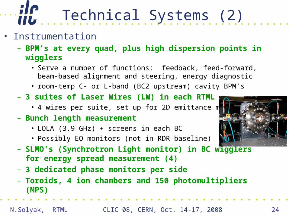
Technical Systems (2)• Instrumentation
– BPM’s at every quad, plus high dispersion points in wigglers• Serve a number of functions: feedback, feed-forward, beam-based
alignment and steering, energy diagnostic
• room-temp C- or L-band (BC2 upstream) cavity BPM’s
– 3 suites of Laser Wires (LW) in each RTML• 4 wires per suite, set up for 2D emittance measurement
– Bunch length measurement• LOLA (3.9 GHz) + screens in each BC
• Possibly EO monitors (not in RDR baseline)
– SLMO’s (Synchrotron Light monitor) in BC wigglers for energy spread measurement (4)
– 3 dedicated phase monitors per side– Toroids, 4 ion chambers and 150 photomultipliers (MPS)

N.Solyak, RTML CLIC 08, CERN, Oct. 14-17, 2008 25
Technical Systems (3)• 1.3 GHz SC RF system plus supporting utilities
– 48 CMs per side (1 RF source per 3 CMs, as in ML)• 3 CM x “8Q” in BC1• 15 RFunits x “9-8Q-9” in BC2• BC1: 2nd source with RF switch for redundancy
– LLRF issues• Phase stability• Beam loading compensation
– Beam loads RF at decelerating phase– Unlike ML, need to “jump” both amplitude and phase of RF
source @ beam time
– Cryo system (~6.5% cost of ML Cryo system)• Part of ML cryogenic system
– Also supports SC solenoids in spin rotator• BC’s are laser-straight
– Probably OK – only ~1 km long

N.Solyak, RTML CLIC 08, CERN, Oct. 14-17, 2008 26
Sources of emittance degradation– Synchrotron radiation
• From DRX arc, turnaround, BC wigglers– Beam-ion instabilities– Beam jitter
• From DR• From stray fields
– Dispersion• DR extraction• Misaligned quads• Rolled bends
– Coupling• DR extraction septum• Rolled quads• Misaligned bends• Quad strength errors in spin rotator
– Pitched RF cavities• Produce time-varying vertical kick
– RF phase jitter• Varies IP arrival time of beams
– Beam halo formation– Collimator and cavity Wakefields – Space charge – Resistive wall wakes in vac. chamber
LET BBA @ ILC RTML
Several BBA used:• Ballistic Alignment (BA)• Kick minimization (KM)• Dispersion Free Steering• Dispersion Bumps• 4D Coupling Correction
• Adaptive alignment• Wakefield Bumps
Feed-Back andFeed Forward system

N.Solyak, RTML CLIC 08, CERN, Oct. 14-17, 2008 27
Survey Alignment

N.Solyak, RTML CLIC 08, CERN, Oct. 14-17, 2008 28
Static tuning in part of RTML (upstream BC1)
COLL2Turnaround Spin rotatorSKEW EMIT2
collimatorSkew
EMIT

N.Solyak, RTML CLIC 08, CERN, Oct. 14-17, 2008 29
Emittance budget(factor ~2 larger)

N.Solyak, RTML CLIC 08, CERN, Oct. 14-17, 2008 30
Cost and its Distribution
• CFS + BC RF system = 68% of costs
– Correlated – much of CFS cost is housing for BC cryomodules
• Remainder dominated by RT beam transport
– Quads, correctors, BPMs, vacuum system
• Small amount of “exotica”– Non-BPM instrumentation,
controls, dumps, collimators
CFS
CM
RF
Cryo
Instrumentation
Dumps + Colls
Vacuum
Magnets + PS
Controls

N.Solyak, RTML CLIC 08, CERN, Oct. 14-17, 2008 31
ILC Damping Ring – New Design
• New ILC DR lattice is shorter.
• Bunch length = 6 mm In old RDR design:
• 9 mm (easy)• 6 mm (more challenge)
• Energy spread = 0.15%
• New DR increases the length of the RTML linac in each side (e+ and e-) of ~300 m, but not CFS
• Need redesign/adjust DRX lattice to accommodate changes in DR
Injection
ExtractionExtraction
Injection
300 m
Layout of the ILC Damping Ringblue - old RDR (2007); red - new DCO (Feb.2008)

N.Solyak, RTML CLIC 08, CERN, Oct. 14-17, 2008 32
Minimum length of separate RTML/source tunnel
• Smaller vertical separation DR/BDS tunnel: 10m 6 m• Length constrains:
•Electron source side (straight) ~ 500 m•Positron source: 950m=500(KAS)+450m(SCL/TRL)
•RTML tunnel length ~ 900 m (now ~1250 m)
Possible configuration of the RTML/source tunnels
DR
BDS
6 m
ML
Service TunnelRTML/e+ KAS RTML/e+
~ 500 m500 m
RTML
BDS ML
DRML
~500 m
300 m
RTML/e-
~10
0 m
~10
0 m
Discussion at Dubna ILC workshop, June, 2008
Possible tunnel saving ~ (600-700) m /side

N.Solyak, RTML CLIC 08, CERN, Oct. 14-17, 2008 33
Short Single stage BC (Eun-San Kim)-2006
• Compress 6mm 0.3mm only• Acceleration 4.515 GeV will require 15 RFunits (incl. 1 spare) ~ 600 m• Energy spread @ 15 GeV 3.5%*(4.5/15) ~ 1%• BC length ~700m. Saving ~ 1100-700 = ~ 400m• No ELBC2 extraction line• Disadvantages: No flexibility, tunability, larger emittance growth ???
N.Solyak, RTML CLIC 08, CERN, Oct. 14-17, 2008 34
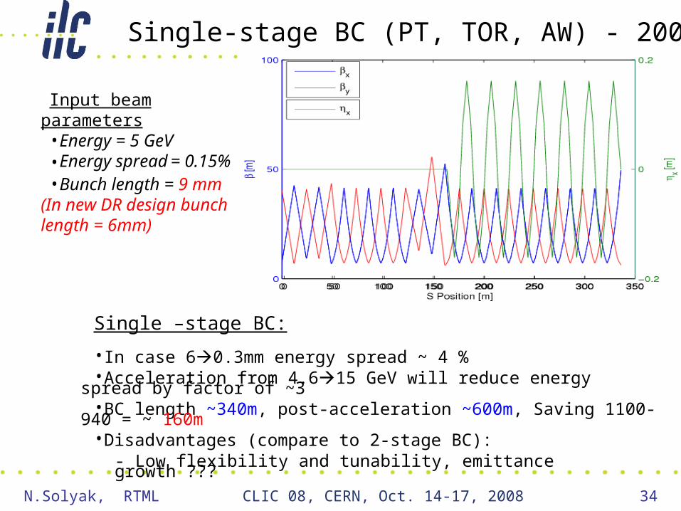
Single –stage BC:
•In case 60.3mm energy spread ~ 4 %•Acceleration from 4.615 GeV will reduce energy spread by
factor of ~3•BC length ~340m, post-acceleration ~600m, Saving 1100-940
= ~ 160m•Disadvantages (compare to 2-stage BC):
- Low flexibility and tunability, emittance growth ???
Input beam parameters•Energy = 5 GeV•Energy spread = 0.15%•Bunch length = 9 mm
(In new DR design bunch length = 6mm)
Single-stage BC (PT, TOR, AW) - 2005

N.Solyak, RTML CLIC 08, CERN, Oct. 14-17, 2008 35
Further RTML work
Study Possible Cost saving options: Minimize length of RTML/source tunnelAlternative 2-stage or 1-stage bunch compressor Reduce pulsed extraction Lines from 3 per side to 2 per side
Lattice design aand emittance studiesRe-evaluate/match geometry and optics to accommodate DR
changes, CFS req’s and cost saving options
Demonstrate require emittance budget for Static tuning
Dynamic tuning (ground motion, jitter, AC magnetic fields, etc)
Design FB/FF system
Design/prototyping critical components

N.Solyak, RTML CLIC 08, CERN, Oct. 14-17, 2008 36
Acknowledgements
RTML team:
SLAC, FNAL, ANL, LBL, Cornell Univ., KEK, DESY, INFN, CERN, KNU/Korea, UBC, IHEP/China
Design and Performance:P. Tenenbaum, J. Smith, S. Molloy, M. Woodley, S. Seletskyi, E.-S. Kim, D.Schulte, A. Latina, K. Kubo, M. Church, L. Wang, P. Spenzouris, M. Venturini, I. Reichel, J.Gao…
Engineering and Civil:V. Kashikhin, P.Bellomo,T.Mattison ,Y.Suetsugu,J. Noonan, X.Qiong, P.Michelato, T.Markiewicz, R.Larsen, M.Wendt, John Carwardine, C.Saunders, T.Peterson, F.Asiri, J.-L Baldy, G.Aarons, T.Lackowski, …