Embed Size (px)
Citation preview
1
RTDS supported Hardware-in-the-loop PMU performance and compliance testing and PMU based applications
Matija NaglicDelft University of TechnologyFaculty of Electrical EngineeringEmail: [email protected]: LB 03.210
2
Part 1: RTDS supported Hardware-in-the-loop PMU performance and compliance testing
3
IEEE Synchrophasor Measurement Test Suite Specification—Version 2 (TSS)
RTDS supported Phasor Measurement Unit (PMU) evaluation platform is based on the TSS specification, which provides unambiguous test plans and requirements for equipment used during compliance testing.
Test procedures are within the normative of:• IEEE Std. C37.118.1-2011• IEEE Std. C37.118.1a-2014
4
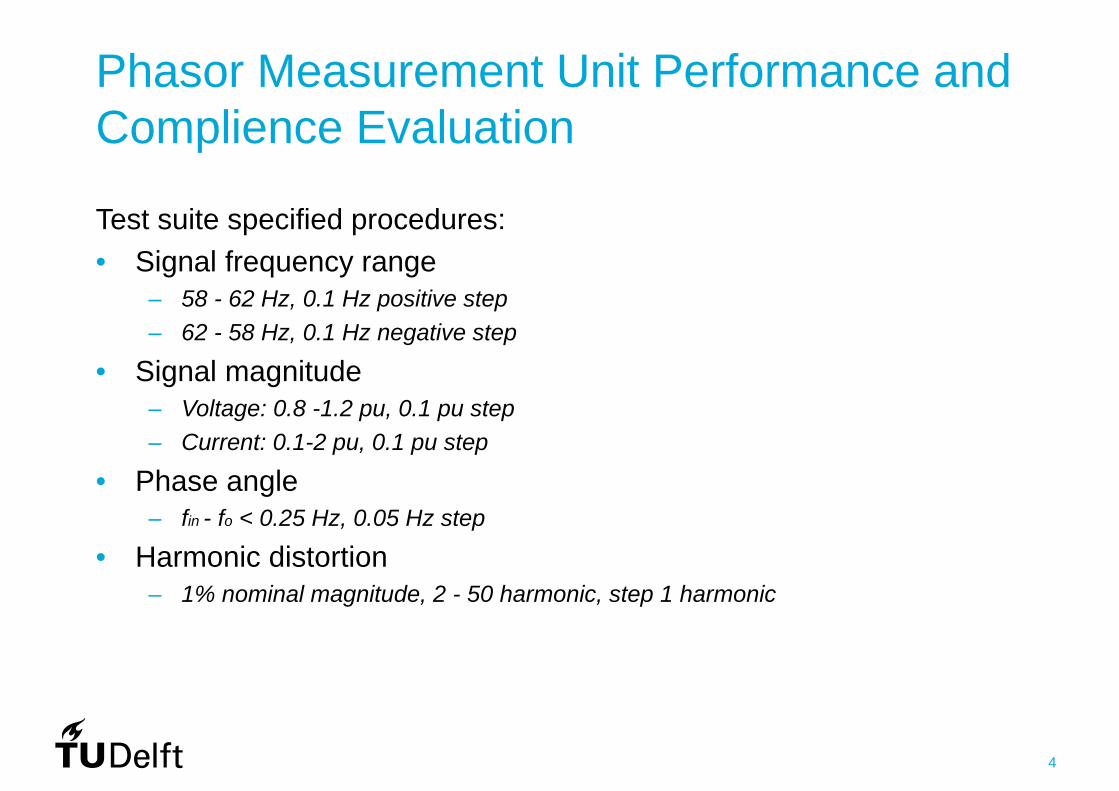
Phasor Measurement Unit Performance and Complience Evaluation
Test suite specified procedures:• Signal frequency range
– 58 - 62 Hz, 0.1 Hz positive step– 62 - 58 Hz, 0.1 Hz negative step
• Signal magnitude – Voltage: 0.8 -1.2 pu, 0.1 pu step– Current: 0.1-2 pu, 0.1 pu step
• Phase angle – fin - fo < 0.25 Hz, 0.05 Hz step
• Harmonic distortion – 1% nominal magnitude, 2 - 50 harmonic, step 1 harmonic
5
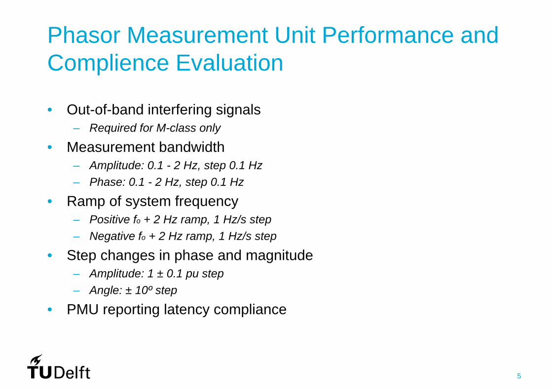
• Out-of-band interfering signals – Required for M-class only
• Measurement bandwidth – Amplitude: 0.1 - 2 Hz, step 0.1 Hz– Phase: 0.1 - 2 Hz, step 0.1 Hz
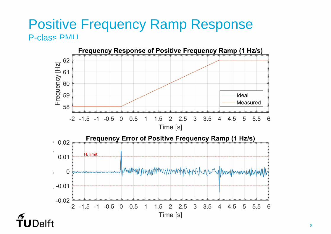
• Ramp of system frequency – Positive fo + 2 Hz ramp, 1 Hz/s step– Negative fo + 2 Hz ramp, 1 Hz/s step
• Step changes in phase and magnitude – Amplitude: 1 ± 0.1 pu step– Angle: ± 10º step
• PMU reporting latency compliance
Phasor Measurement Unit Performance and Complience Evaluation
6
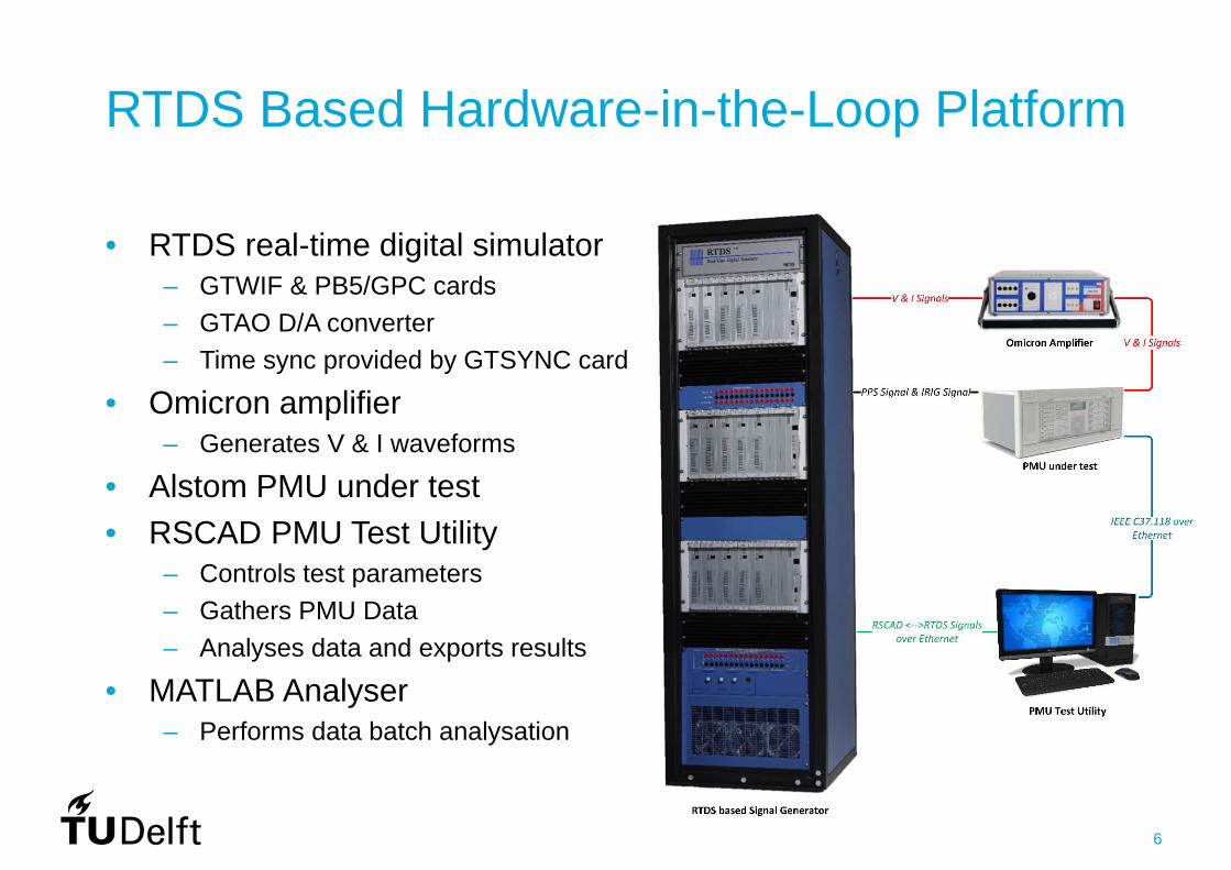
RTDS Based Hardware-in-the-Loop Platform
• RTDS real-time digital simulator– GTWIF & PB5/GPC cards– GTAO D/A converter– Time sync provided by GTSYNC card
• Omicron amplifier – Generates V & I waveforms
• Alstom PMU under test• RSCAD PMU Test Utility
– Controls test parameters– Gathers PMU Data – Analyses data and exports results
• MATLAB Analyser– Performs data batch analysation
7
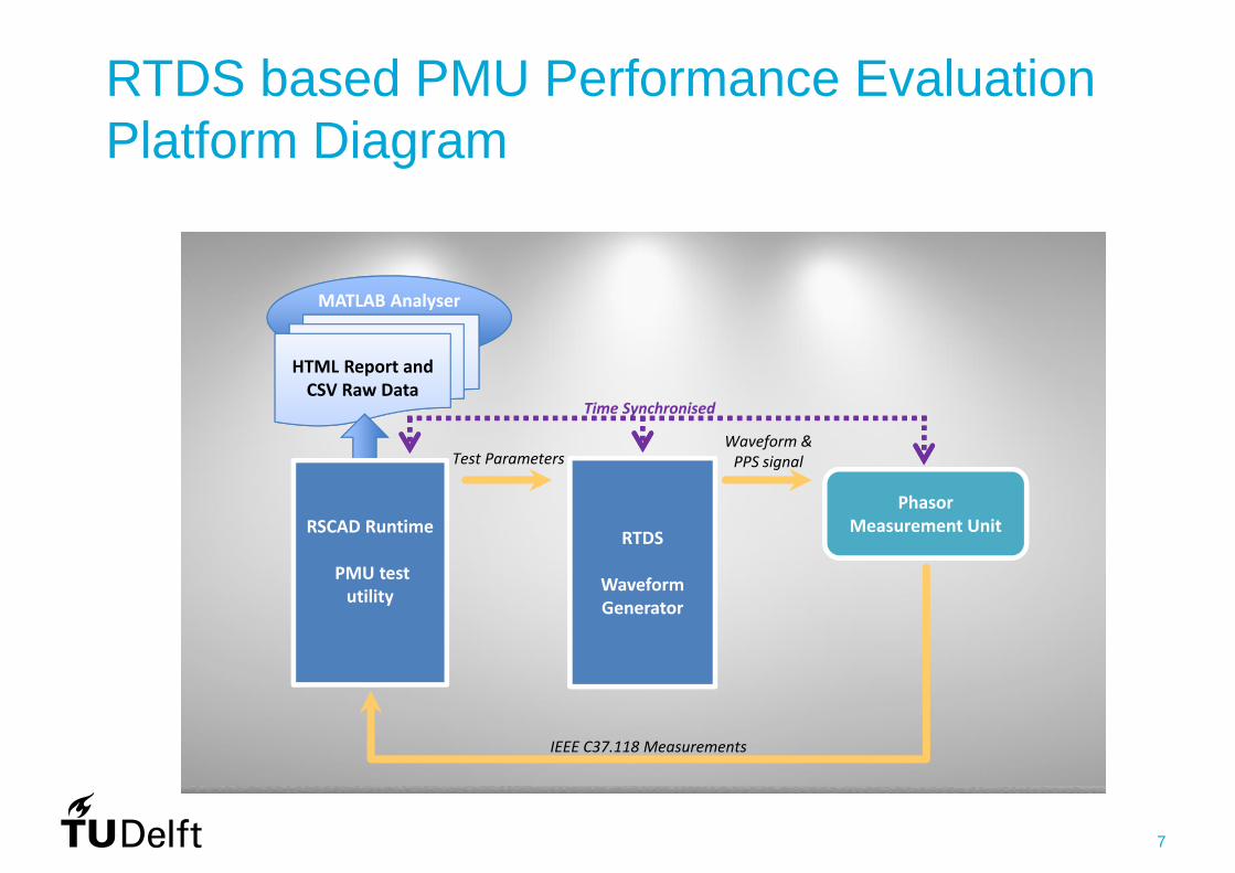
RTDS based PMU Performance Evaluation Platform Diagram
RTDS
Waveform Generator
Test Parameters
Phasor Measurement Unit
Waveform & PPS signal
IEEE C37.118 Measurements
MATLAB Analyser
Time Synchronised
HTML Report and CSV Raw Data
RSCAD Runtime
PMU test utility
8
Positive Frequency Ramp ResponseP-class PMU
FE limit

9
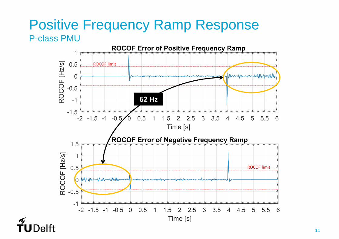
Positive Frequency Ramp ResponseP-class PMU
ROCOF limit

10
Positive Frequency Ramp ResponseP-class PMU
58 Hz
ROCOF limit
ROCOF limit
11
Positive Frequency Ramp ResponseP-class PMU
62 Hz
ROCOF limit
ROCOF limit
12
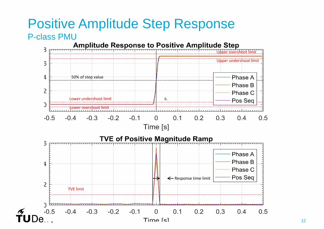
50% of step value
Lower overshoot limit
Lower undershoot limit
Upper undershoot limit
Upper overshoot limit
t0
Positive Amplitude Step ResponseP-class PMU
Response time limit
TVE limit

13
PMU Evaluation ResultsTest Pass/ Fail Test
Test type Test subtype Frequency ROCOF TVE
Steady state Signal Frequency Range Steady state Signal Magnitude—Voltage Steady state Signal Magnitude—Current Steady state Phase Angle Deviation Steady state Harmonic Distortion Steady state Out‐of‐Band Interference (Required for M class only)
Dynamic Measurement Bandwidth—phase modulation Dynamic Measurement Bandwidth—amplitude modulation Dynamic Ramp of System Frequency Dynamic Step Change in Phase
Delay: Response: Overshoot:
Dynamic Step Change in Magnitude
Delay: Response: Overshoot:Latency PMU Reporting Latency (Not performed)

14

15
Part 2: Phasor Measurement Unit data driven Applications
16
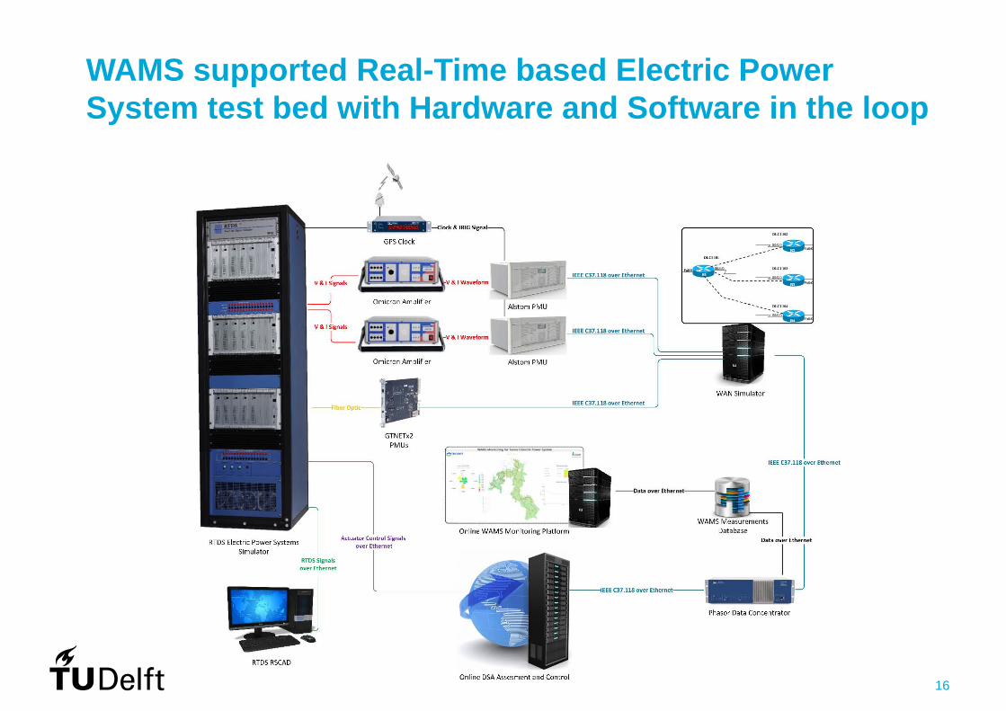
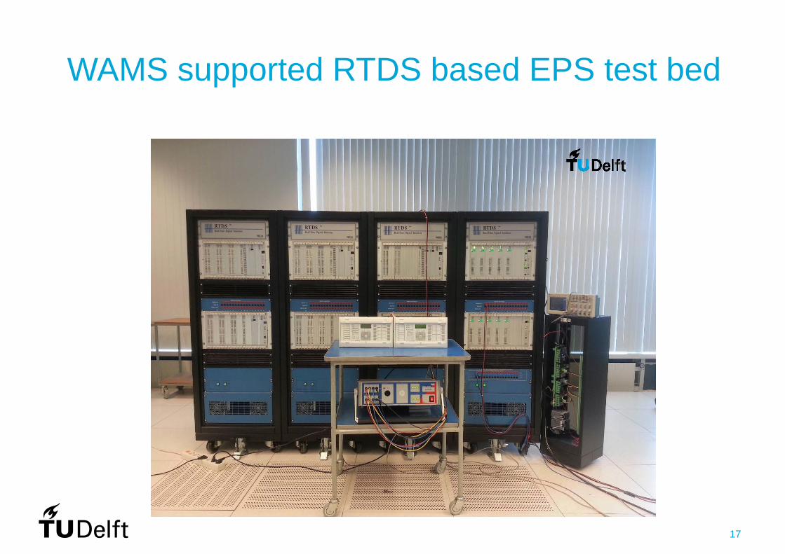
WAMS supported Real-Time based Electric Power System test bed with Hardware and Software in the loop
17
WAMS supported RTDS based EPS test bed
18
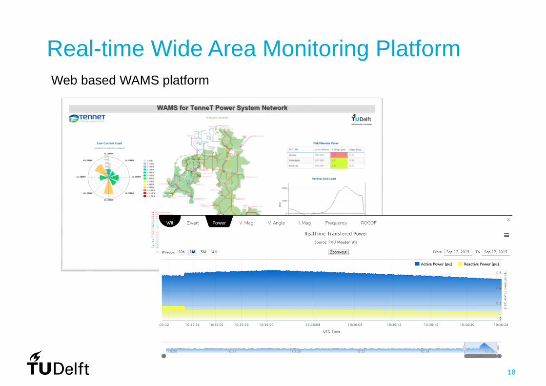
Web based WAMS platform
Real-time Wide Area Monitoring Platform
19
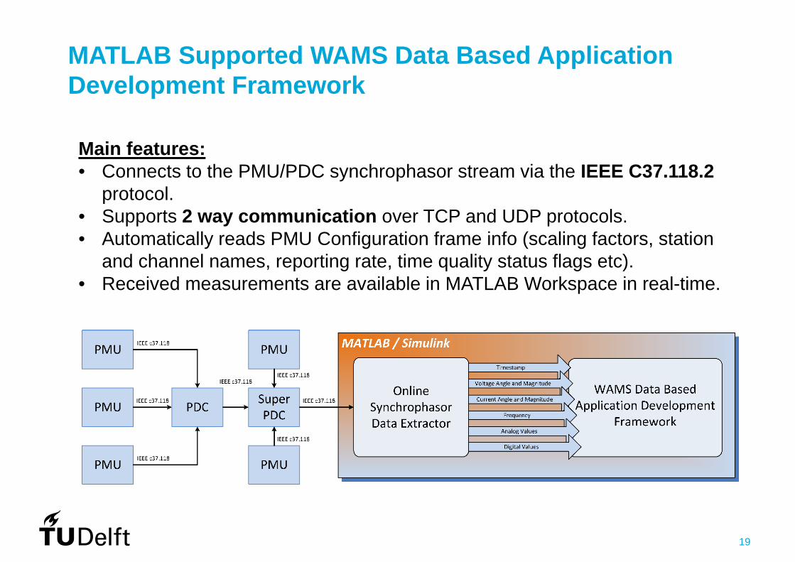
MATLAB Supported WAMS Data Based Application Development Framework
Main features:• Connects to the PMU/PDC synchrophasor stream via the IEEE C37.118.2
protocol. • Supports 2 way communication over TCP and UDP protocols.• Automatically reads PMU Configuration frame info (scaling factors, station
and channel names, reporting rate, time quality status flags etc).• Received measurements are available in MATLAB Workspace in real-time.
20
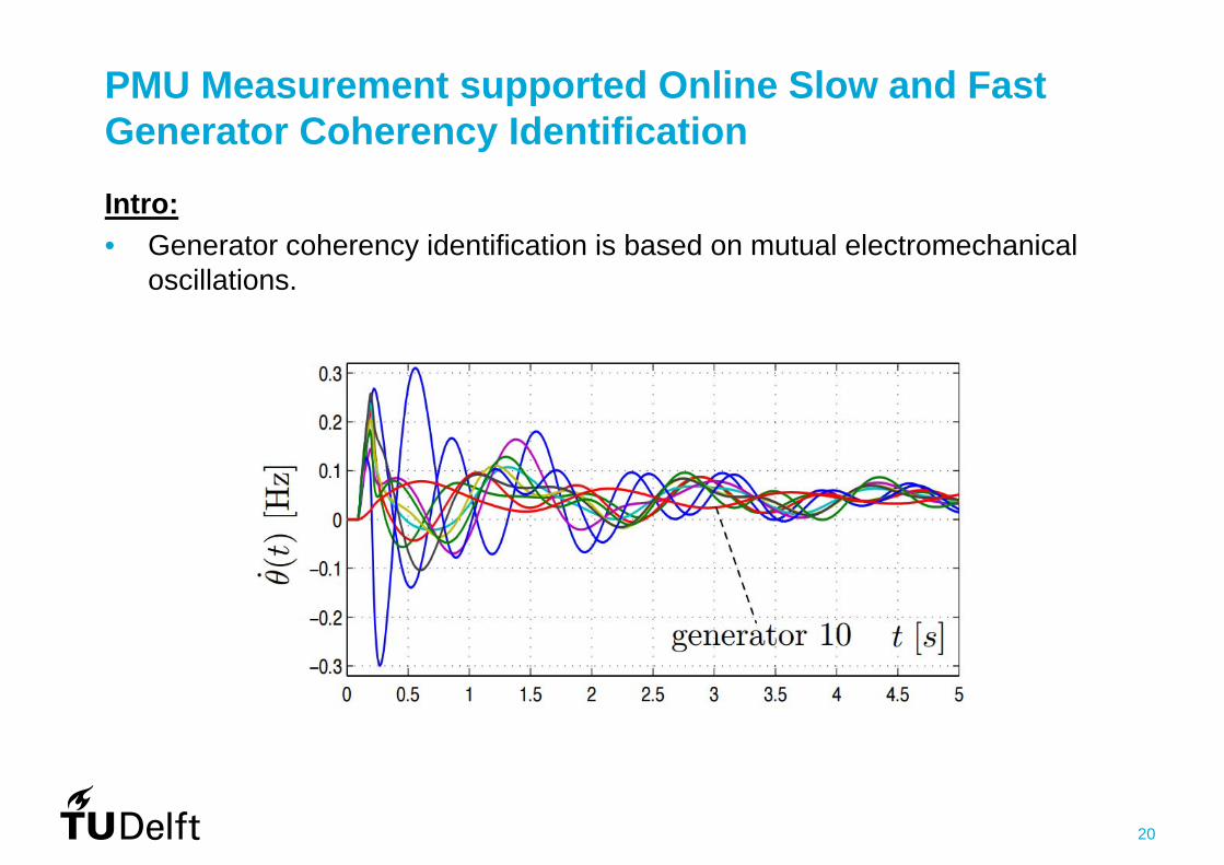
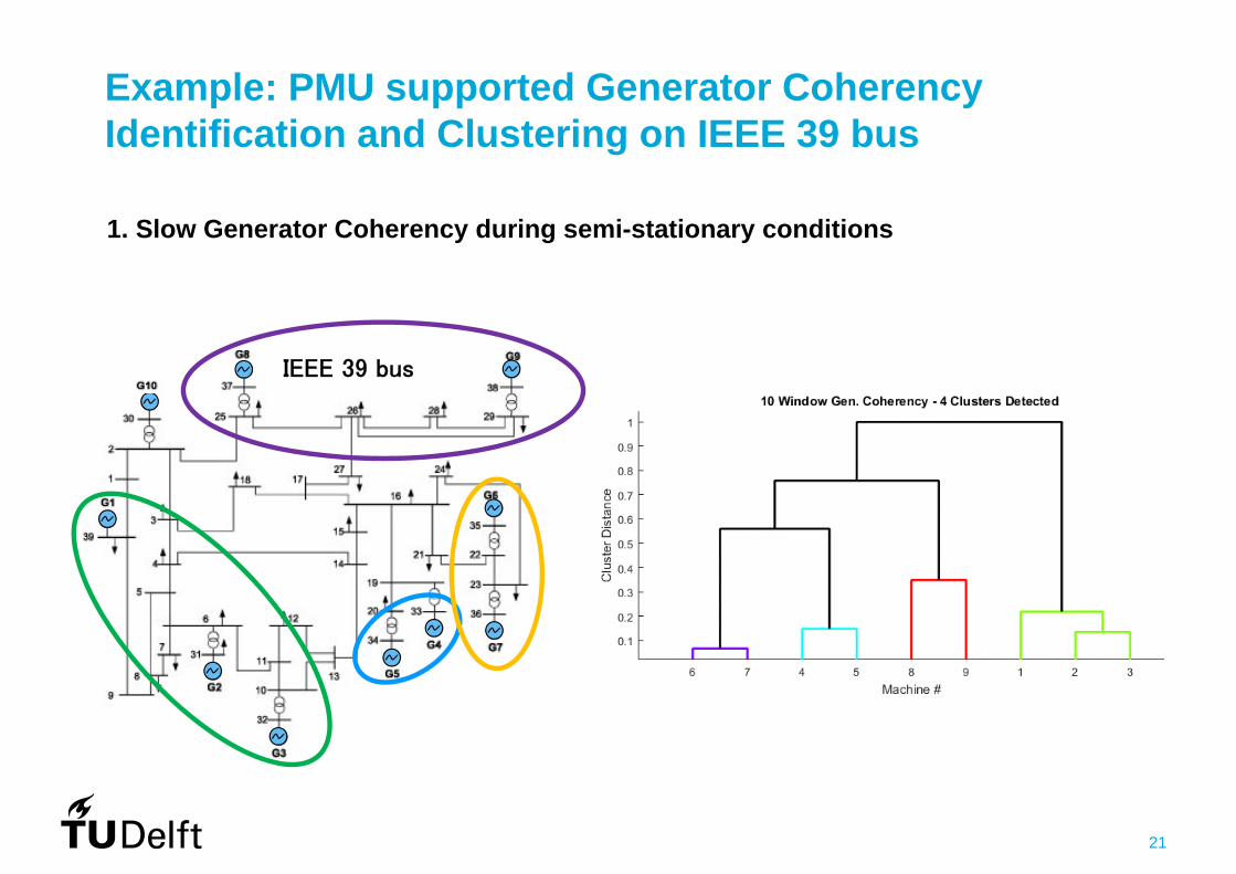
PMU Measurement supported Online Slow and Fast Generator Coherency Identification
Intro:• Generator coherency identification is based on mutual electromechanical
oscillations.
21
1. Slow Generator Coherency during semi-stationary conditions
IEEE 39 bus
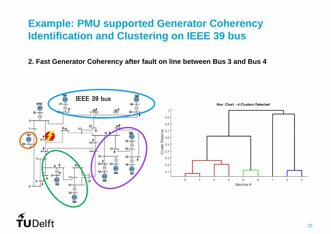
Example: PMU supported Generator Coherency Identification and Clustering on IEEE 39 bus
22
IEEE 39 bus
Example: PMU supported Generator Coherency Identification and Clustering on IEEE 39 bus
2. Fast Generator Coherency after fault on line between Bus 3 and Bus 4
23
Conclussion
• IEEE Synchrophasor Measurement Test Suite Specification—Version 2 provides solid framework for PMU performance evaluation platforms.
• Better PMU estimation algorithm required under dynamic conditions.
• RTDS based PMU performance evaluation platform uncertainty is under investigation.
• MATLAB Supported WAMS Data Based Application Development Framework serves as a valuable tool fot fast prototyping and testing of online synchrophasor based applications.
• With using WAMS supported real-time electric power system testbed the performance of each component can be evaluated and exanimated towards overall performance of the proposed WAMS based solution.
24
Publications
• P. Ceferin, M. Naglic, A. Souvent, Wide Area Monitoring Systems and Information and Communication Technology Networks, accepted for CIGREScience & Engineering Journal, June 2016
• M. Naglic, I. Tyuryukanov, M. Popov, M. V. D. Meijden, V. Terzija: Phasor Measurement Unit supported Online Generator Slow-Coherency Identification, under review for MedPower 2016
• I. Tyuryukanov, J. Quiros-Tortos, M. Naglic, M. Popov, M. V. D. Meijden, V. Terzija, Controlled Islanding of Power Networks based on Graph Reduction and Spectral Clustering, under review for MedPower 2016
• M. Popov, M. Naglic, I.Tyuryukanov, G. Rietveld, M. van der Meijden, A contribution to Synchrophasor Testing and HIL testing of PMUs for systemdisturbance monitoring, accepted for IEEE PES GM Panel Session 2016
25
Experience with testing of negative sequence relays for the protection
against internal motor faults
M. PopovDelft University of TechnologyFaculty of Electrical Engineering
Master Thesis ofAravinth T.S.

26
Scenario
A turn‐turn fault occurred in one phase of an Induction Motor’s stator Asymmetrical voltage causing bearing damage (pitting) , little reduction in RPM
(vibratory) Fault was not detected by the relay resulting in a development of the turn‐turn
fault into Phase‐Phase fault after 9 minutes Tripping of the system after 9 minutes at extremely high current Final scenario: Stator Core damage, Rotor and accessories due to excessive heating
(Unplanned shutdown and production loss)
27
PROBLEM STATEMENT
Failure of Protection system to detect the turn‐turn fault at the inception stage
RESEARCH QUESTION
The reason behind the failure of imminent fault detection
Setting of the motor protection relay, if employed
28
APPROACH
1. Literature review on Internal faults in Induction motors and Protective relaying
2. Formulation of algebraic equations for modeling Turn‐Turn fault
3. Simulation of Turn‐Turn fault in EMTP‐ATP MODELS (Dynamic State)
4. Obtain COMTRADE file (.PL4 / .CFG)
5. Feed COMTRADE file into Omicron for Secondary Current Injection
6. Testing of Siprotec‐4 protection relay (7SJ645) for Negative sequence & Over
current protection for various levels of fault severity in stator
7. Propose Optimised Protection settings
Simulation Testing Optimization
COMTRADE: Common Format for Transient Data Exchange for Power Systems
29
SIMULATION

30
DOW NETWORK MODEL
Swing 87 Bus
87-3-12 87-2-9
SM99-1 SM99-1
99-2-599-1-5
M
M
CTCTR
M
M
MODELvolt3fas
CTCTR
MODELvolt3fas
PM-3201B
Torque
IM WI
Damping
InertiaU(0)
+
Load modelTLMC
M
CTCTR
PM-3201A
Torque
IM WI
Damping
InertiaU(0)
+
Load modelTLMC
TR-99-2BC
T
Y
U(0)
+
I
T
T
T
T
400V LVM1
Torque
IM WI
f(u)
Damping
I
M
InertiaU(0)
+PM-3201C
IM
Damping
I
M
InertiaU(0)
+PM-3201C
IM
MODELtor1
Torque(init)
InertiaU(0)
+
MODELtor1
Torque(init)
InertiaU(0)
+TR-99-2B
CT
Y
U(0)
+
I
T
T
T
T
400V LVM1A
Torque
IM WI
f(u)
M
PTCTR
1.45MW 1.45MW
700kW700kW
11kV 40kA
Source: DOW Benelux, Terneuzen
Power 1450 kWVoltage 11 kVCurrent 95 A
Speed 742 1/min
Pole pairs 4
Torque 18662 Nm
Stator Resistance 0.6177 ohm
Stator Leakage Inductance 0.0252 H
Rotor Resistance 1.8524 ohm
Rotor Leakage Inductance 0.0109 H
Mutual Inductance 0.5312 H
31
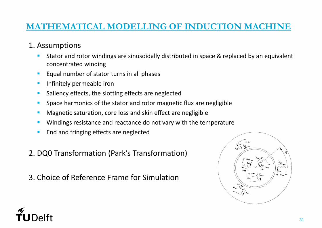
MATHEMATICAL MODELLING OF INDUCTION MACHINE
1. Assumptions Stator and rotor windings are sinusoidally distributed in space & replaced by an equivalent
concentrated winding Equal number of stator turns in all phases Infinitely permeable iron Saliency effects, the slotting effects are neglected Space harmonics of the stator and rotor magnetic flux are negligible Magnetic saturation, core loss and skin effect are negligible Windings resistance and reactance do not vary with the temperature End and fringing effects are neglected
2. DQ0 Transformation (Park’s Transformation)
3. Choice of Reference Frame for Simulation
32
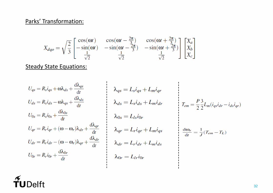
Parks’ Transformation:
Steady State Equations:
33
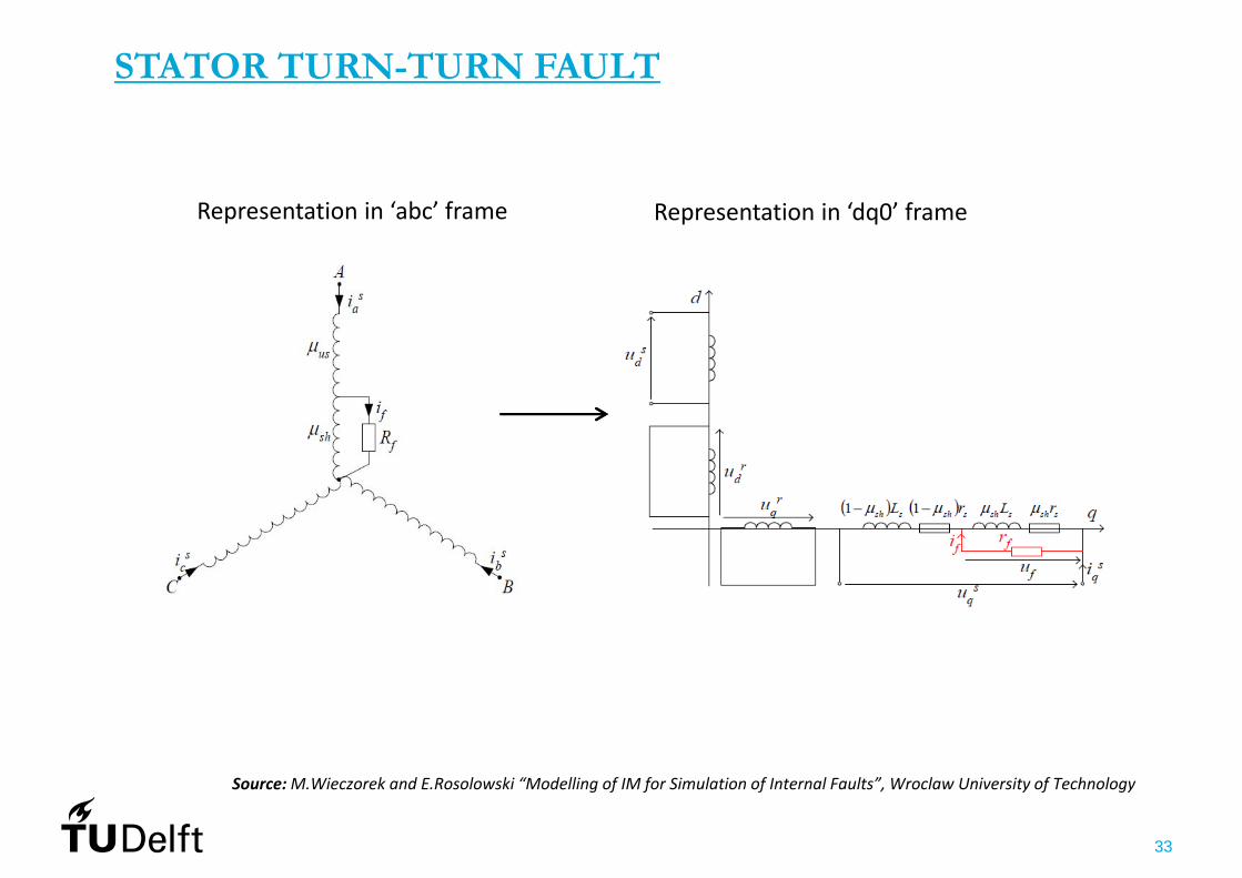
STATOR TURN-TURN FAULT
Representation in ‘abc’ frame Representation in ‘dq0’ frame
Source:M.Wieczorek and E.Rosolowski “Modelling of IM for Simulation of Internal Faults”, Wroclaw University of Technology
34
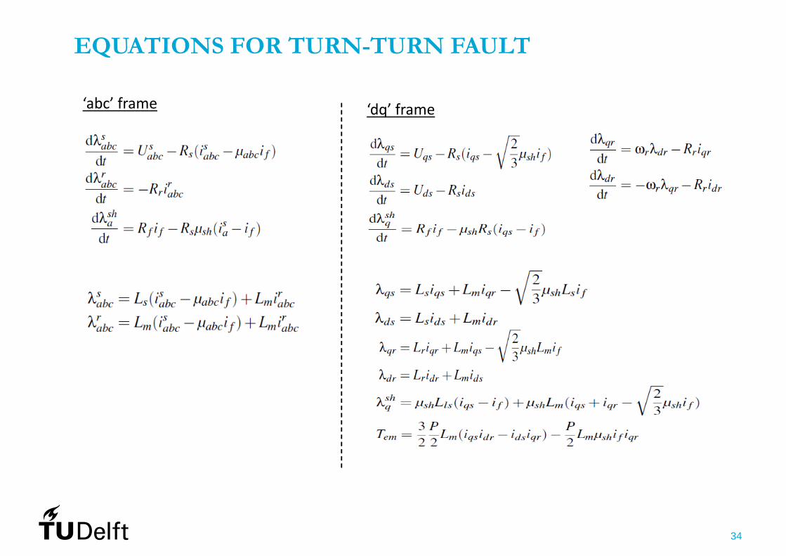
EQUATIONS FOR TURN-TURN FAULT
‘abc’ frame ‘dq’ frame
35
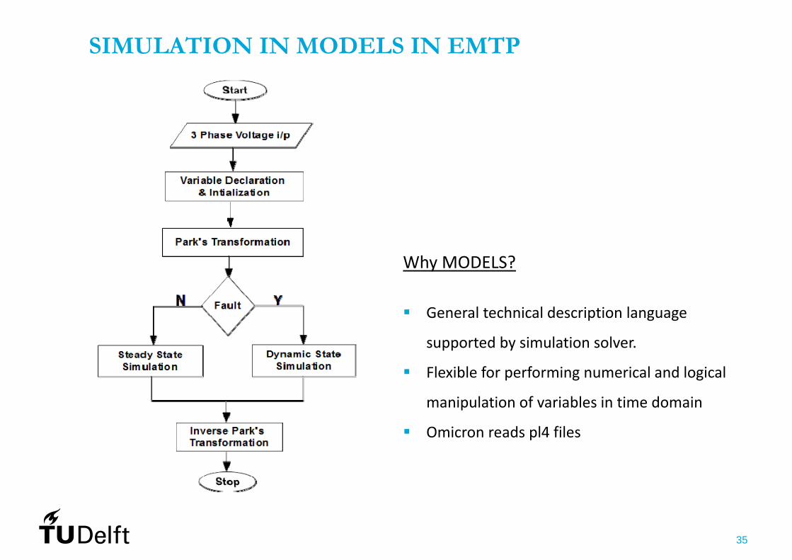
SIMULATION IN MODELS IN EMTP
Why MODELS?
General technical description language
supported by simulation solver.
Flexible for performing numerical and logical
manipulation of variables in time domain
Omicron reads pl4 files
36
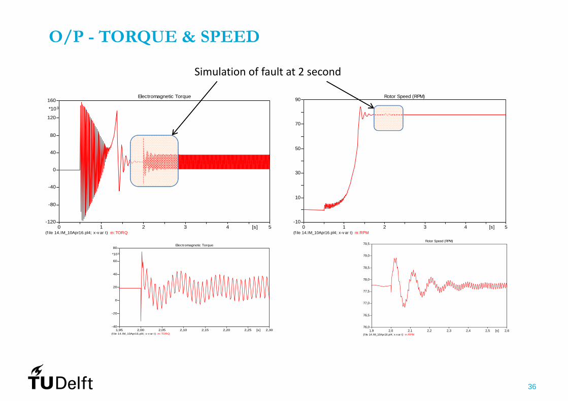
O/P - TORQUE & SPEED
(f ile 14.IM_10Apr16.pl4; x-v ar t) m:TORQ 0 1 2 3 4 5[s]
-120
-80
-40
0
40
80
120
160
*103
Electromagnetic Torque
(f ile 14.IM_10Apr16.pl4; x-v ar t) m:TORQ 1,95 2,00 2,05 2,10 2,15 2,20 2,25 2,30[s]
-40
-20
0
20
40
60
80
*103
Electromagnetic Torque
(f ile 14.IM_10Apr16.pl4; x-v ar t) m:RPM 0 1 2 3 4 5[s]
-10
10
30
50
70
90 Rotor Speed (RPM)
(f ile 14.IM_10Apr16.pl4; x-v ar t) m:RPM 1,9 2,0 2,1 2,2 2,3 2,4 2,5 2,6[s]
76,0
76,5
77,0
77,5
78,0
78,5
79,0
79,5Rotor Speed (RPM)
Simulation of fault at 2 second
37
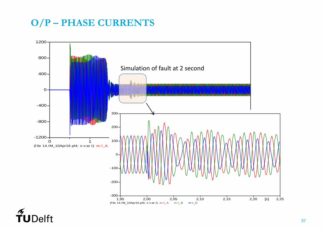
O/P – PHASE CURRENTS
(f ile 14.IM_10Apr16.pl4; x-v ar t) m:I_A m:I_B m:I_C 0 1 2 3 4 5[s]
-1200
-800
-400
0
400
800
1200
(f ile 14.IM_10Apr16.pl4; x-v ar t) m:I_A m:I_B m:I_C 1,95 2,00 2,05 2,10 2,15 2,20 2,25[s]
-300
-200
-100
0
100
200
300
Simulation of fault at 2 second

38
O/P – FAULT CURRENT
(f ile 14.IM_10Apr16.pl4; x-v ar t) m:IFAULT 0 1 2 3 4 5[s]
-1000
-800
-600
-400
-200
0
200
400
600
Large circulating current in the faulty portion Faulty portion acts like autotransformer Terminal Current is not affected much Fast progression in turn‐turn fault

39
TESTING
40
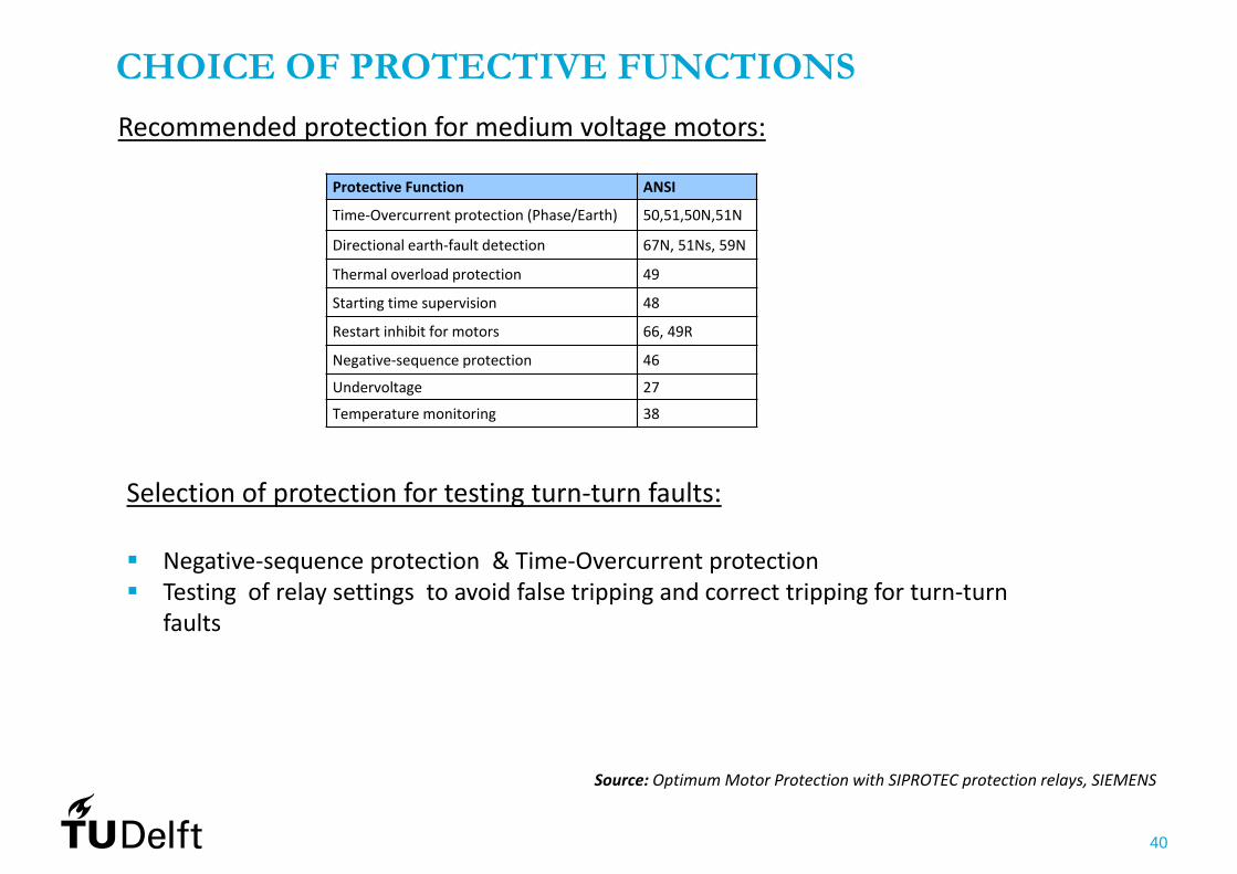
CHOICE OF PROTECTIVE FUNCTIONS
Recommended protection for medium voltage motors:
Protective Function ANSI
Time‐Overcurrent protection (Phase/Earth) 50,51,50N,51N
Directional earth‐fault detection 67N, 51Ns, 59N
Thermal overload protection 49
Starting time supervision 48
Restart inhibit for motors 66, 49R
Negative‐sequence protection 46
Undervoltage 27
Temperature monitoring 38
Selection of protection for testing turn‐turn faults:
Negative‐sequence protection & Time‐Overcurrent protection Testing of relay settings to avoid false tripping and correct tripping for turn‐turn
faults
Source: Optimum Motor Protection with SIPROTEC protection relays, SIEMENS
41
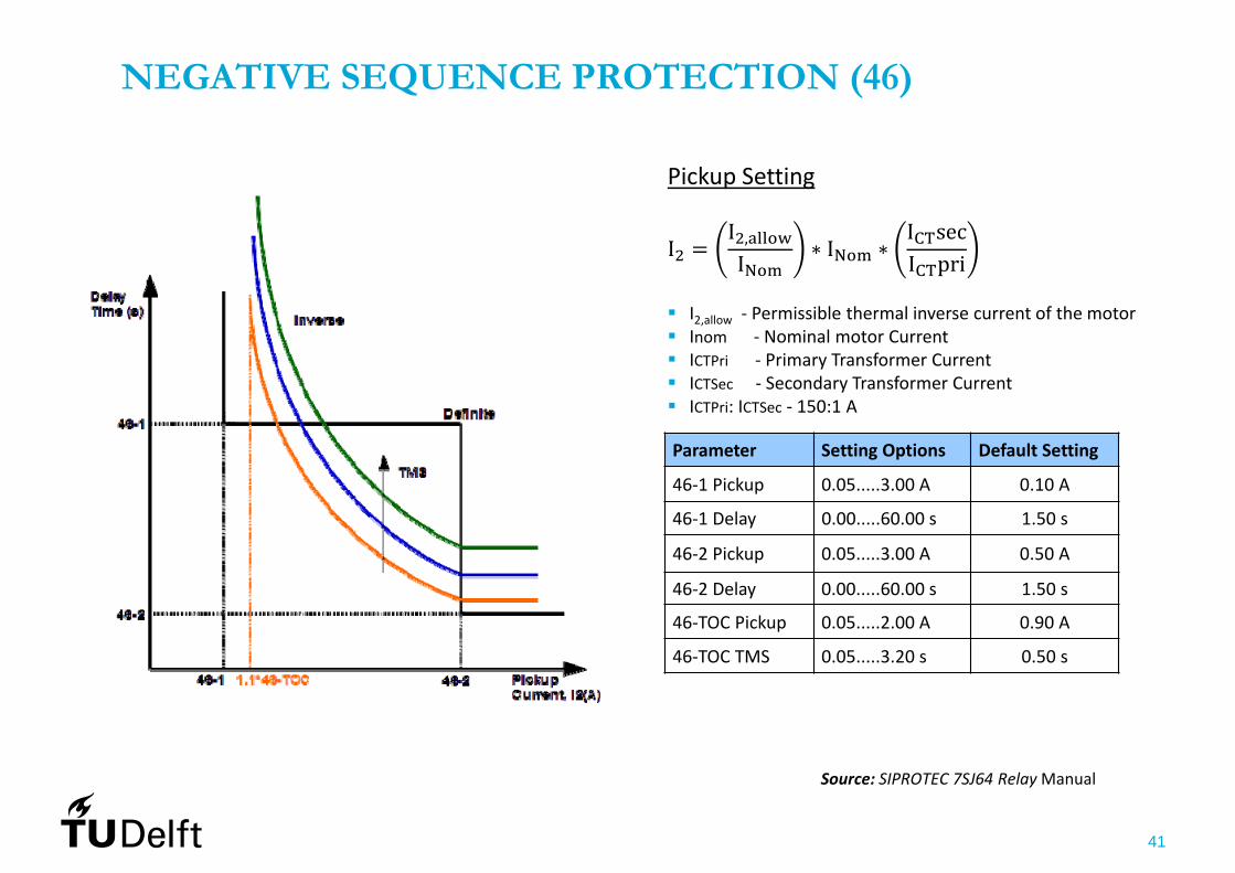
NEGATIVE SEQUENCE PROTECTION (46)
Parameter Setting Options Default Setting
46‐1 Pickup 0.05.....3.00 A 0.10 A
46‐1 Delay 0.00.....60.00 s 1.50 s
46‐2 Pickup 0.05.....3.00 A 0.50 A
46‐2 Delay 0.00.....60.00 s 1.50 s
46‐TOC Pickup 0.05.....2.00 A 0.90 A
46‐TOC TMS 0.05.....3.20 s 0.50 s
Source: SIPROTEC 7SJ64 Relay Manual
II ,I ∗ I ∗
I secI pri
I2,allow ‐ Permissible thermal inverse current of the motor Inom ‐ Nominal motor Current ICTPri ‐ Primary Transformer Current ICTSec ‐ Secondary Transformer Current ICTPri: ICTSec ‐ 150:1 A
Pickup Setting
42
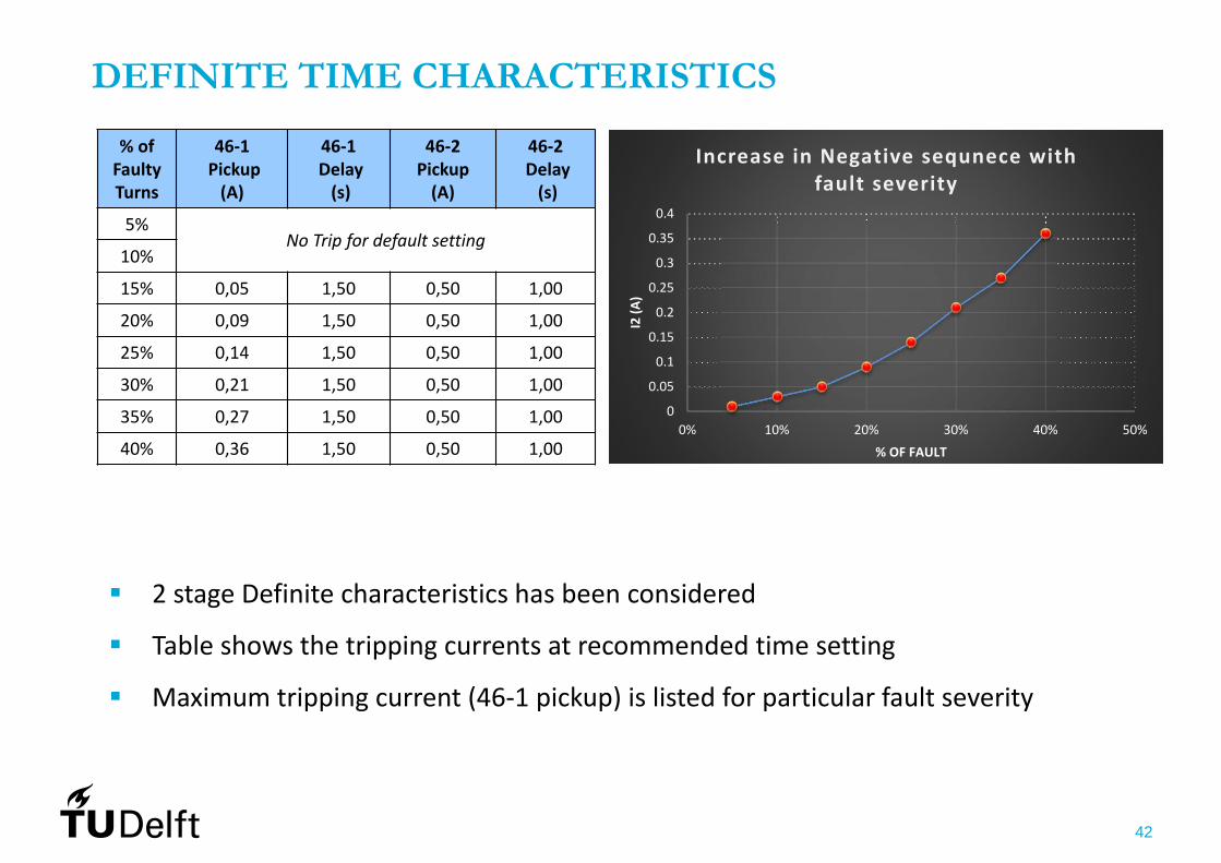
% of FaultyTurns
46‐1Pickup(A)
46‐1Delay(s)
46‐2 Pickup(A)
46‐2Delay(s)
5%No Trip for default setting
10%
15% 0,05 1,50 0,50 1,00
20% 0,09 1,50 0,50 1,00
25% 0,14 1,50 0,50 1,00
30% 0,21 1,50 0,50 1,00
35% 0,27 1,50 0,50 1,00
40% 0,36 1,50 0,50 1,00
DEFINITE TIME CHARACTERISTICS
2 stage Definite characteristics has been considered
Table shows the tripping currents at recommended time setting
Maximum tripping current (46‐1 pickup) is listed for particular fault severity
0
0.05
0.1
0.15
0.2
0.25
0.3
0.35
0.4
0% 10% 20% 30% 40% 50%
I2 (A
)
% OF FAULT
Increase in Negative sequnece with fault severity
43
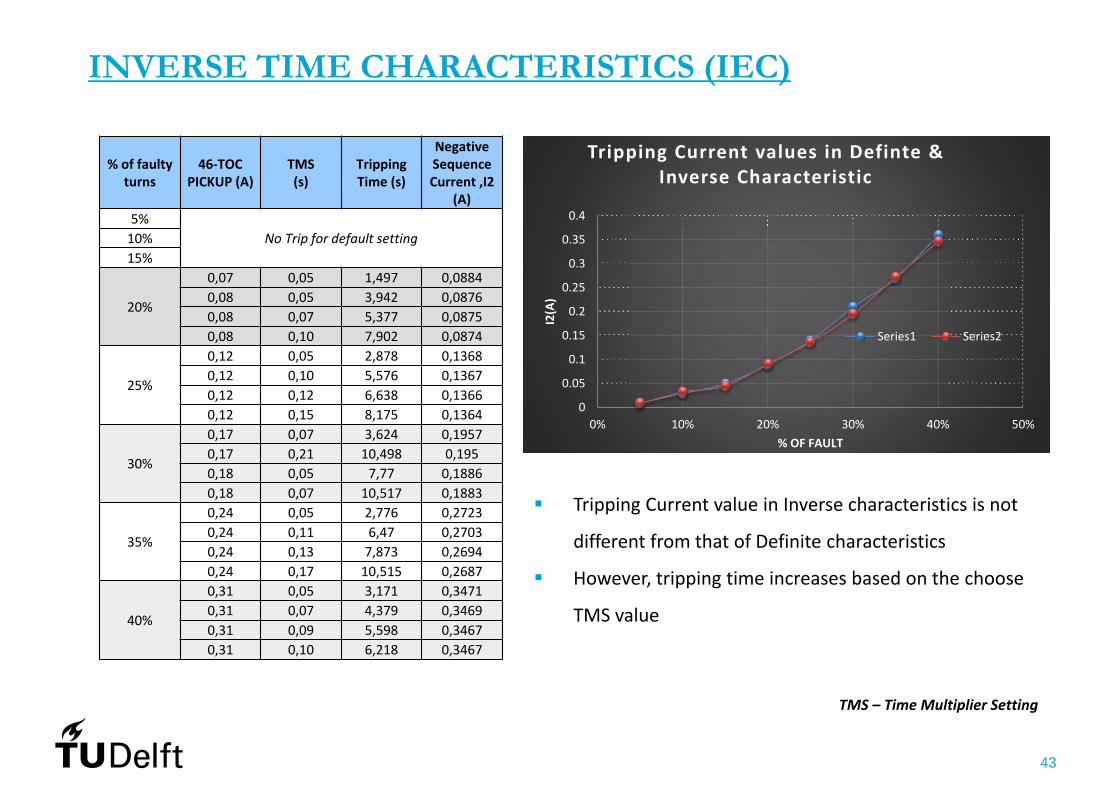
INVERSE TIME CHARACTERISTICS (IEC)
% of faultyturns
46‐TOC PICKUP (A)
TMS (s)
Tripping Time (s)
Negative Sequence Current ,I2
(A)5%
No Trip for default setting10%15%
20%
0,07 0,05 1,497 0,08840,08 0,05 3,942 0,08760,08 0,07 5,377 0,08750,08 0,10 7,902 0,0874
25%
0,12 0,05 2,878 0,13680,12 0,10 5,576 0,13670,12 0,12 6,638 0,13660,12 0,15 8,175 0,1364
30%
0,17 0,07 3,624 0,19570,17 0,21 10,498 0,1950,18 0,05 7,77 0,18860,18 0,07 10,517 0,1883
35%
0,24 0,05 2,776 0,27230,24 0,11 6,47 0,27030,24 0,13 7,873 0,26940,24 0,17 10,515 0,2687
40%
0,31 0,05 3,171 0,34710,31 0,07 4,379 0,34690,31 0,09 5,598 0,34670,31 0,10 6,218 0,3467
0
0.05
0.1
0.15
0.2
0.25
0.3
0.35
0.4
0% 10% 20% 30% 40% 50%
I2(A)
% OF FAULT
Tripping Current values in Definte & Inverse Characteristic
Series1 Series2
Tripping Current value in Inverse characteristics is not
different from that of Definite characteristics
However, tripping time increases based on the choose
TMS value
TMS – Time Multiplier Setting

44
OBSERVATIONS ON TESTING
For approximately the same value of current in Inverse Characteristic setting, tripping time is
large. This may allow high current for longer time thus heating the insulation which lead to
faster propagation of turn‐turn fault
Hence, Definite Time characteristics with appropriate setting shall be applied for turn‐turn fault
(in case of Negative Sequence Protection)
FUTURE WORK
Testing of Siprotec relay(7SJ645) for Time Overcurrent protection
Compare Negative sequence protection and Overcurrent protection for turn‐turn fault
Propose a general relation between fault severity and protection parameter settings

45
THANK YOU!!