Embed Size (px)
Citation preview
Test&Measurement
ProductBrochure|03.00R&S®FSH4/FSH8
HandheldSpectrumAnalyzerWheremobilitycounts

2
Easy-to-replace battery.
TheR&S®FSHspectrumanalyzerisrugged,handyanddesignedforuseinthefield.Itslowweight,itssimple,well-conceivedoperationandthelargenumberofmeasurementfunctionsmakeitanindispensabletoolforanyonewhoneedsanefficientmeasuringinstrumentforoutdoorwork.
The R&S®FSH is a spectrum analyzer and, depending on the model and the options installed, a power meter, a cable and antenna tester and a two-port vector network analyzer. It provides the three most important RF analysis functions that an RF service technician or an installation and maintenance team needs to solve daily routine mea-surement tasks. For example, it can be used for main-taining or installing transmitter systems, checking cables and antennas, assessing signal quality in broadcasting, radiocommunications and service, measuring electric field strength or in simple lab applications. The R&S®FSH can perform any of these tasks quickly, reliably and with high measurement accuracy.
Weighting only 3 kg, the R&S®FSH is a handy instrument. All frequently used functions have their own function keys and are within reach of your fingertips. The brilliant color display is easy to read even under poor lighting conditions and has a monochrome mode for extreme conditions.
The capacity of the R&S®FSH battery enables you to work without interruptions for up to 4.5 hours. The battery is changed within seconds. And if it rains? No problem – all connectors are splash-proof.
Key facts ❙ Frequency range from 9 kHz to 3.6 GHz or 8 GHz ❙ High sensitivity (< –141 dBm (1 Hz), with preamplifier < –161 dBm (1 Hz))
❙ Low measurement uncertainty (< 1 dB) ❙ Measurement functions for all important measurement tasks related to the startup and maintenance of trans-mitter systems
❙ Internal tracking generator and VSWR bridge with built-in DC voltage supply (bias)
❙ Two-port network analyzer ❙ Easy-to-replace Li-ion battery for up to 4.5 h of operation ❙ Rugged, splash-proof housing for rough work in the field ❙ Easy handling due to low weight (3 kg with battery) and easy-to-reach function keys
❙ Saving of measurement results on SD card ❙ LAN and USB interface for remote control and transfer of measurement data
❙ R&S®FSH4View software for simple documentation of measurement results
R&S®FSH4/FSH8HandheldSpectrumAnalyzerAtaglance

Rohde & Schwarz R&S®FSH4/FSH8 Handheld Spectrum Analyzer 3
R&S®FSH with fold-out stand for desktop use.
Installation and maintenance of transmitter stations (base stations) ❙ Power measurements on pulsed signals ❙ Channel power measurements ❙ Adjacent channel power measurements ❙ Measurements of spurious emissions (spectrum emission mask)
❙ Measurements of the modulation spectrum on pulsed signals with gated sweep
❙ Analysis of 3GPP WCDMA transmit signals ❙ Analysis of CDMA2000® transmit signals ❙ Distance-to-fault measurements ❙ Two-port vector network analysis ❙ Scalar network analysis ❙ One-port cable loss measurements ❙ Vector voltmeter ❙ Power measurements up to 18 GHz ❙ Directional power measurements up to 4 GHz ▷ page 4
Measurements of electromagnetic fields ❙ Field strength measurements with directional antenna ❙ Field strength measurements with isotropic antenna ▷ page 10
Diagnostic applications in the lab or in service ❙ General spectrum analysis ❙ AM modulation depth measurements ❙ Measurements of signal distortions caused by harmonics ❙ Location of EMC problems ▷ page 11
Documentation and remote control ❙ R&S®FSH4View software for documenting measurement results
❙ Remote control via LAN or USB ▷ page 12
Easy operation ❙ Quick function selection via keypad and rotary knob ❙ Optimal reading of measurement results in any situation ❙ Setting of frequency via channel tables ❙ Easy-to-access, well-protected connectors ▷ page 13
R&S®FSH4/FSH8HandheldSpectrumAnalyzerBenefitsandkeyfeatures

4
The R&S®FSH is designed for the installation and mainte-nance of transmitter systems. For this purpose, it provides the following measurement functions: ❙ Checking of signal quality in the spectral and time domain with channel power measurements and measurements on pulsed signals
❙ Distance-to-fault measurements on cables and one-port cable loss measurements
❙ Measuring of antenna match and testing of power amplifiers with vector network analysis
❙ Determination of transmission power with power sensors
Power measurements on pulsed signalsBy means of the TDMA POWER function, the R&S®FSH performs time-domain power measurements within a time division multiple access (TDMA) timeslot. To make work easier for the user, all required instrument settings are already predefined for the GSM and EDGE standards.
Channel power measurementsThe R&S®FSH determines the power of a definable trans-mission channel by means of the channel power measure-ment function. A channel power measurement for the LTE, 3GPP WCDMA, cdmaOne and CDMA2000® 1x digital mo-bile radio standards is performed at a keystroke.
Adjacent channel power measurementsThe ACLR measurement function enables the user to test how far a base station carrier signal reaches into the adja-cent channel. An ACLR value that is too low indicates poor signal quality and can lead to the interference of the adja-cent useful signals.
The adjacent channel power can be displayed as an ab-solute value or relative to the useful carrier. The R&S®FSH offers predefined settings for various transmission stan-dards such as 3GPP WCDMA, CDMA2000® 1x or LTE, but parameters can also be user-defined. Users can, for example, enter different channel widths and spacings for up to 12 channels and up to 12 adjacent channels for the measurement of multicarrier signals.
Installationandmaintenanceoftransmitterstations(basestations)
Channel power measurement.
ACLR measurment of a 3GPP WCDMA signal with four
carriers.
TDMA power measurement.
Rohde & Schwarz R&S®FSH4/FSH8 Handheld Spectrum Analyzer 5
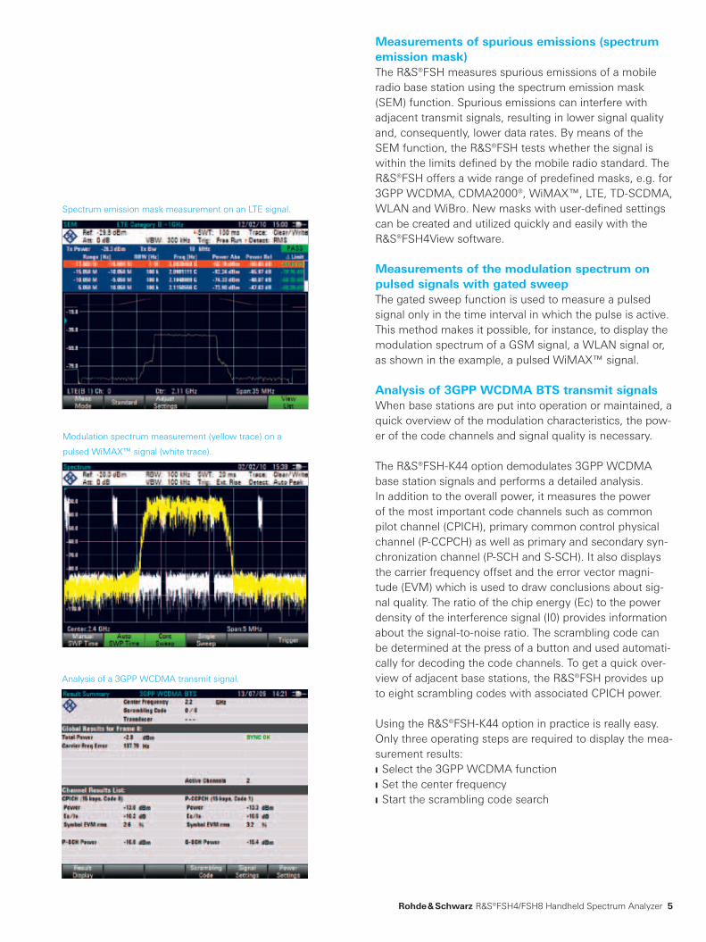
Measurements of spurious emissions (spectrum emission mask)The R&S®FSH measures spurious emissions of a mobile radio base station using the spectrum emission mask (SEM) function. Spurious emissions can interfere with adjacent transmit signals, resulting in lower signal quality and, consequently, lower data rates. By means of the SEM function, the R&S®FSH tests whether the signal is within the limits defined by the mobile radio standard. The R&S®FSH offers a wide range of predefined masks, e.g. for 3GPP WCDMA, CDMA2000®, WiMAX™, LTE, TD-SCDMA, WLAN and WiBro. New masks with user-defined settings can be created and utilized quickly and easily with the R&S®FSH4View software.
Measurements of the modulation spectrum on pulsed signals with gated sweepThe gated sweep function is used to measure a pulsed signal only in the time interval in which the pulse is active. This method makes it possible, for instance, to display the modulation spectrum of a GSM signal, a WLAN signal or, as shown in the example, a pulsed WiMAX™ signal.
Analysis of 3GPP WCDMA BTS transmit signalsWhen base stations are put into operation or maintained, a quick overview of the modulation characteristics, the pow-er of the code channels and signal quality is necessary.
The R&S®FSH-K44 option demodulates 3GPP WCDMA base station signals and performs a detailed analysis. In addition to the overall power, it measures the power of the most important code channels such as common pilot channel (CPICH), primary common control physical channel (P-CCPCH) as well as primary and secondary syn-chronization channel (P-SCH and S-SCH). It also displays the carrier frequency offset and the error vector magni-tude (EVM) which is used to draw conclusions about sig-nal quality. The ratio of the chip energy (Ec) to the power density of the interference signal (I0) provides information about the signal-to-noise ratio. The scrambling code can be determined at the press of a button and used automati-cally for decoding the code channels. To get a quick over-view of adjacent base stations, the R&S®FSH provides up to eight scrambling codes with associated CPICH power.
Using the R&S®FSH-K44 option in practice is really easy. Only three operating steps are required to display the mea-surement results: ❙ Select the 3GPP WCDMA function ❙ Set the center frequency ❙ Start the scrambling code search
Analysis of a 3GPP WCDMA transmit signal.
Modulation spectrum measurement (yellow trace) on a
pulsed WiMAX™ signal (white trace).
Spectrum emission mask measurement on an LTE signal.

6
Analysis of CDMA2000® transmit signalsThe R&S®FSH-K46 option enables the R&S®FSH for CDMA2000® base station transmitter measurements. In addition to total power, the spectrum analyzer determines the power of the pilot channel (F-PICH) and synchroniza-tion channel (F-SYNC) code channels. The frequency offset of the carrier frequency as well as error vector magnitude (EVM) and Rho are also measured and displayed. This al-lows the user to detect transmitter impairments such as clipping or intermodulation that are difficult to recognize from the spectrum alone.
For in-depth analysis, the R&S®FSH-K46E option is avail-able for code domain power measurements. This option permits the graphical display of the channel power of oc-cupied and unoccupied channels. The resulting summary provides an overview of the main signal parameters, e.g. total power, channel power, Rho and EVM. Channel power is displayed relative to total power or relative to the power of the pilot channel.
The code domain channel list contains additional informa-tion such as symbol rate and channel number with the as-sociated Walsh code.
Distance-to-fault measurementsThe distance-to-fault, caused by a pinched cable or by loose or corroded cable connections, is determined quick-ly and precisely. The built-in threshold function ensures that only true cable faults, i.e. faults that exceed a toler-ance limit, are displayed in a list. This considerably simpli-fies the evaluation of the measurement.
Distance-to-fault (DTF) measurement.
The code domain power measurement provides an overview
of the most important signal parameters.
Analysis of a CDMA2000® transmit signal with the
R&S®FSH-K46 option.

Rohde & Schwarz R&S®FSH4/FSH8 Handheld Spectrum Analyzer 7
Scalar transmission measurement.
Two-port vector network analysisThe “vector measurements” option transforms the R&S®FSH models with built-in tracking generator and inter-nal VSWR bridge into a two-port vector network analyzer. Matching and transmission characteristics of filters, ampli-fiers, etc., can be determined quickly and with high accu-racy in the forward and reverse direction with only one test setup. The built-in DC bias supplies power to active DUTs such as amplifiers via the RF cable. This function is espe-cially useful for mast-mounted amplifiers of a mobile radio base station. ❙ Increased measurement accuracy due to vector system error correction
❙ Measurement of magnitude and phase of S-parameters S11, S21, S12 and S22
❙ Simultaneous display of magnitude and phase in split-screen mode
❙ Smith chart with zoom function ❙ Support of all conventional marker formats ❙ Input of a reference impedance for DUTs with an impedance that is not 50 Ω
❙ Electrical length measurement ❙ Determination of group delay
Scalar network analysisIf you do not need the advantages of vector network analysis for reflection and transmission measurements, the R&S®FSH models featuring a built-in tracking generator are a more cost-effective solution for determining the trans-mission characteristics of cables, filters and amplifiers. The R&S®FSH models with a built-in VSWR bridge (models .24 and .28) can, in addition, measure the matching (return loss, reflection coefficient or VSWR), e.g. of an antenna.
One-port cable loss measurementsThe R&S®FSH can determine the cable loss of installed cables without much effort. It is sufficient to connect one end of the cable to the R&S®FSH measurement port. The other end of the cable is terminated with a short circuit or left open.
Vector network analysis: display of magnitude and phase.
Vector network analysis: measurement with Smith chart.
8
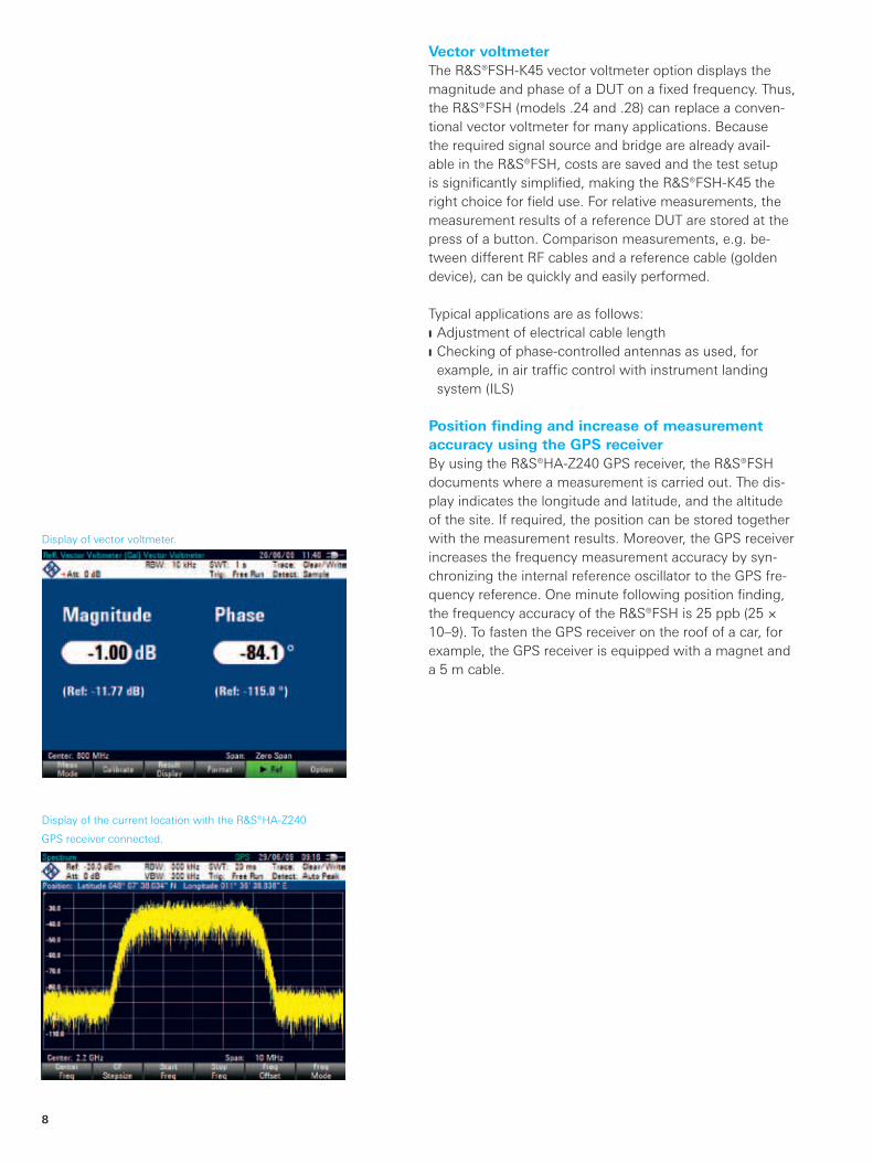
Vector voltmeterThe R&S®FSH-K45 vector voltmeter option displays the magnitude and phase of a DUT on a fixed frequency. Thus, the R&S®FSH (models .24 and .28) can replace a conven-tional vector voltmeter for many applications. Because the required signal source and bridge are already avail-able in the R&S®FSH, costs are saved and the test setup is significantly simplified, making the R&S®FSH-K45 the right choice for field use. For relative measurements, the measurement results of a reference DUT are stored at the press of a button. Comparison measurements, e.g. be-tween different RF cables and a reference cable (golden device), can be quickly and easily performed.
Typical applications are as follows: ❙ Adjustment of electrical cable length ❙ Checking of phase-controlled antennas as used, for example, in air traffic control with instrument landing system (ILS)
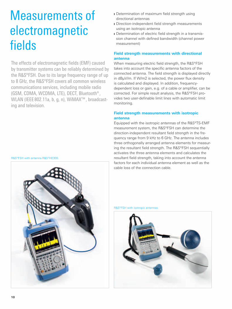
Position finding and increase of measurement accuracy using the GPS receiver By using the R&S®HA-Z240 GPS receiver, the R&S®FSH documents where a measurement is carried out. The dis-play indicates the longitude and latitude, and the altitude of the site. If required, the position can be stored together with the measurement results. Moreover, the GPS receiver increases the frequency measurement accuracy by syn-chronizing the internal reference oscillator to the GPS fre-quency reference. One minute following position finding, the frequency accuracy of the R&S®FSH is 25 ppb (25 × 10–9). To fasten the GPS receiver on the roof of a car, for example, the GPS receiver is equipped with a magnet and a 5 m cable.
Display of the current location with the R&S®HA-Z240
GPS receiver connected.
Display of vector voltmeter.

Rohde & Schwarz R&S®FSH4/FSH8 Handheld Spectrum Analyzer 9
Power measurements up to 18 GHzEquipped with the R&S®FSH-Z1 and R&S®FSH-Z18 power sensors, the R&S®FSH becomes a highly accurate RF power meter up to 8 GHz or 18 GHz with a measurement range from –67 dBm to +23 dBm.
Directional power measurements up to 4 GHz under operating conditionsThe R&S®FSH-Z14 and R&S®FSH-Z44 directional power sensors transform the R&S®FSH into a full-featured direc-tional power meter for the frequency ranges from 25 MHz to 1 GHz and from 200 MHz to 4 GHz. The R&S®FSH can then simultaneously measure the output power and the matching of transmitter system antennas under operating conditions. The power sensors measure average power up to 120 W and normally eliminate the need for any extra attenuators. They are compatible with the common GSM/EDGE, 3GPP WCDMA, cdmaOne, CDMA2000®1x, DVBT and DAB standards. In addition, the peak envelope power (PEP) up to max. 300 W can be determined..
R&S®FSH and R&S®FSH-Z1 terminating power sensor. R&S®FSH and R&S®FSH-Z44 directional power sensor.
10
R&S®FSH with isotropic antennas.
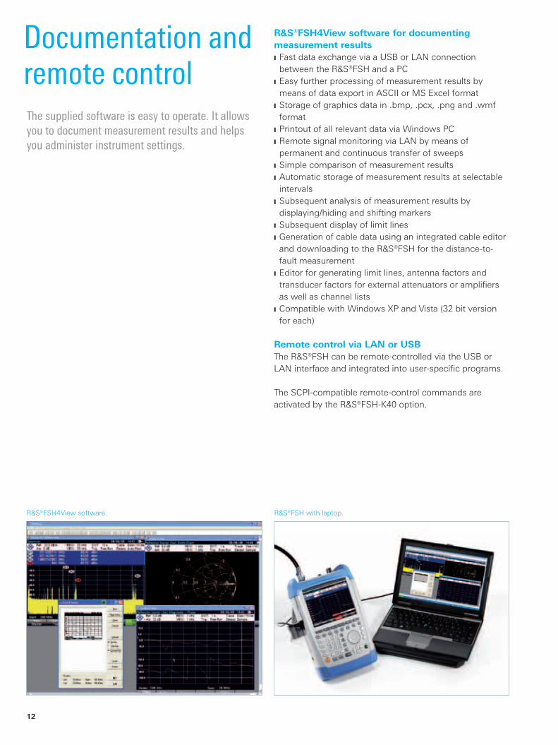
R&S®FSH with antenna R&S®HE300.
MeasurementsofelectromagneticfieldsTheeffectsofelectromagneticfields(EMF)causedbytransmittersystemscanbereliablydeterminedbytheR&S®FSH.Duetoitslargefrequencyrangeofupto8GHz,theR&S®FSHcoversallcommonwirelesscommunicationsservices,includingmobileradio(GSM,CDMA,WCDMA,LTE),DECT,Bluetooth®,WLAN(IEEE802.11a,b,g,n),WiMAX™,broadcast-ingandtelevision.
❙ Determination of maximum field strength using directional antennas
❙ Direction-independent field strength measurements using an isotropic antenna
❙ Determination of electric field strength in a transmis-sion channel with defined bandwidth (channel power measurement)
Field strength measurements with directional antennaWhen measuring electric field strength, the R&S®FSH takes into account the specific antenna factors of the connected antenna. The field strength is displayed directly in dBμV/m. If W/m2 is selected, the power flux density is calculated and displayed. In addition, frequency- dependent loss or gain, e.g. of a cable or amplifier, can be corrected. For simple result analysis, the R&S®FSH pro-vides two user-definable limit lines with automatic limit monitoring.
Field strength measurements with isotropic antennaEquipped with the isotropic antennas of the R&S®TS-EMF measurement system, the R&S®FSH can determine the direction-independent resultant field strength in the fre-quency range from 9 kHz to 6 GHz. The antenna includes three orthogonally arranged antenna elements for measur-ing the resultant field strength. The R&S®FSH sequentially activates the three antenna elements and calculates the resultant field strength, taking into account the antenna factors for each individual antenna element as well as the cable loss of the connection cable.

Rohde & Schwarz R&S®FSH4/FSH8 Handheld Spectrum Analyzer 11
The R&S®FSH is suitable, for example, for the following applications: ❙ Frequency and level measurements ❙ Power measurements up to 18 GHz with the accuracy of a power meter
❙ Measurements on amplifiers, filters, etc., using vector network analysis
❙ Automated creation of test sequences by remote control via LAN or USB
AM modulation depth measurementsThe R&S®FSH measures the modulation depth of an AM signal at the push of a button. The AM modulation depth measurement function positions one marker each on the carrier, the upper sideband and the lower sideband and uses the sideband suppression to determine the modula-tion depth. The modulation frequency can be predefined to selectively determine the modulation depth of a two-tone signal, for example by starting with the 90 Hz sideband and then moving to the 150 Hz sideband of an ILS signal.
Measurements of signal distortions caused by harmonicsThe R&S®FSH determines the harmonics of a device under test, e.g. an amplifier, with the harmonic distortion mea-surement function. In addition to the graphical display of the harmonics, the R&S®FSH also calculates and displays the total harmonic distortion (THD).
Location of EMC problemsThe R&S®HZ-15 near-field probes are used as diagnostic tools for locating EMC problems, e.g. on circuit boards, integrated circuits, cables and shieldings. The R&S®HZ-15 near-field probe set is adequate for emission measure-ments from 30 MHz to 3 GHz. The R&S®HZ-16 preampli-fier improves measurement sensitivity up to 3 GHz, with approx. 20 dB gain and a noise figure of 4.5 dB. In combi-nation with the R&S®FSH, the preamplifier and near-field probe set are a cost-effective means of analyzing and locating disturbance sources during development.
R&S®FSH with near-field probes and DUT.
DiagnosticapplicationsinthelaborinserviceThefold-outstandturnstheR&S®FSHintoadesktopanalyzerforworkinthelaborinservice.
12
R&S®FSH4View software for documenting measurement results ❙ Fast data exchange via a USB or LAN connection between the R&S®FSH and a PC
❙ Easy further processing of measurement results by means of data export in ASCII or MS Excel format
❙ Storage of graphics data in .bmp, .pcx, .png and .wmf format
❙ Printout of all relevant data via Windows PC ❙ Remote signal monitoring via LAN by means of permanent and continuous transfer of sweeps
❙ Simple comparison of measurement results ❙ Automatic storage of measurement results at selectable intervals
❙ Subsequent analysis of measurement results by displaying/hiding and shifting markers
❙ Subsequent display of limit lines ❙ Generation of cable data using an integrated cable editor and downloading to the R&S®FSH for the distance-to-fault measurement
❙ Editor for generating limit lines, antenna factors and transducer factors for external attenuators or amplifiers as well as channel lists
❙ Compatible with Windows XP and Vista (32 bit version for each)
Remote control via LAN or USBThe R&S®FSH can be remote-controlled via the USB or LAN interface and integrated into user-specific programs.
The SCPI-compatible remote-control commands are activated by the R&S®FSH-K40 option.
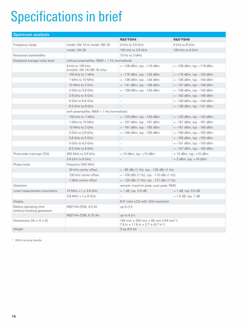
R&S®FSH4View software.
DocumentationandremotecontrolThesuppliedsoftwareiseasytooperate.Itallowsyoutodocumentmeasurementresultsandhelpsyouadministerinstrumentsettings.
R&S®FSH with laptop.

Rohde & Schwarz R&S®FSH4/FSH8 Handheld Spectrum Analyzer 13
Quick function selection via keypad and rotary knobThe R&S®FSH is operated via the keypad and rotary knob.The selected function can be activated directly using the Enter button that is integrated in the rotary knob. Due to the vertical design, you can easily reach all operating ele-ments with your fingers. You can switch between different operating modes (e.g. “spectrum analyzer”, “vector net-work analyzer”, “power meter”) using the MODE key.
All basic settings can be conveniently set in a straightfor-ward list. Measurement results including instrument set-tings are saved to the internal memory or the replaceable SD memory card. Predefined instrument settings can be locked to prevent them from being changed unintention-ally. This reduces the danger of incorrect measurements.
Frequently required measurements can be summarized in a single menu using the USER key. User-defined instru-ment setups are then assigned to the softkeys under an individually selectable name.
For documentation purposes, the contents of a screenshot can be saved as a graphics file.
Optimal reading of measurement results in any situationThe measurement results on the bright, 6.5” VGA color display are easy to read. The backlighting of the display can be adjusted to the ambient lighting conditions. For use in extremely strong sunlight, a special monochrome mode provides optimal contrast.
Setting of frequency via channel tablesAs an alternative to entering a frequency, you can tune the R&S®FSH by means of channel numbers. The channel number is displayed instead of the center frequency. Users who are familiar with channel assignments from common TV or mobile radio applications can operate the R&S®FSH even more easily. TV channel tables for a large number of countries are supplied with the R&S®FSH.
Straightforward menus for easy selection of functions.
Allfrequentlyusedfunctionssuchasreferencelevel,bandwidthsandfrequencycanbesetdirectlyviakeys.
Easyoperation
Easy configuration of instrument setup.
Selecting the channel table.

14
Frontansicht
RFinput
Connectorforheadphones
JExt.triggerinput
JExt.referenceinput
JIFoutput/videooutput
JBiasinput
JConnectorforaccessories
LAN/USBinterface
Simplemenu-based
operationviasoftkeys
Functionkeys
Kensingtonlock
Call-upofuser-defined
settings
Connectorforpowersensor
Trackinggeneratoroutput
SDmemorycard
ColorLCD(640×480pixels),canbe
switchedtohigh-contrastmonochrome
displayinextremesunlight
Selectionbetweendifferentoperatingmodes
(“spectrumanalyzer”,“vectornetwork
analyzer”,“powermeter”,etc.)
Selectionofthemeasurementfunction
(channelpower,occupiedbandwidth,etc.)
Generalinstrumentsetup
Screenshot
RotaryknobwithEnterbutton
Cursorkeys
Additional connectors (e.g. for LAN and USB) are protected by caps.
Operation in national languageThe user interface of the R&S®FSH is available in various national languages. Almost all of the softkeys, operat-ing instructions and messages can be displayed in the selected national language. The R&S®FSH supports the following languages: English, Korean, Japanese, Chinese, Russian, Italian, Spanish, Portuguese, French, Hungarian and German.
Easy-to-access, well-protected connectorsAdditional inputs/outputs such as the DC voltage supply (bias), interfaces and the SD card are easily accessible under dust-proof caps on the side of the instrument.

Rohde & Schwarz R&S®FSH4/FSH8 Handheld Spectrum Analyzer 15
Altogether six R&S®FSH models for different applications and frequency ranges are available. The R&S®FSH4 and R&S®FSH8 can perform measurements up to an upper fre-quency limit of 3.6 GHz and 8 GHz, respectively. Models featuring a built-in tracking generator can also be used to determine the transmission characteristics of cables, filters, amplifiers, etc.
Additional models with built-in tracking generator and internal VSWR bridge are available for distance-to-fault (DTF) measurements, matching measurements and vector network analysis. All models have an adjustable pream-plifier, making them suitable for measuring very small signals. Two power sensors are available as accessories – for precise terminating power measurements up to 18 GHz and for directional power measurements up to 4 GHz. The following tables show possible configurations for different standard functions and applications as well as an overview of available models.
SystemconfigurationOptionsandapplications
Standard functionsApplication
R&S®FSH4/8 model
TDMA power measurements
Channel power measurements
Field strength measurements/measurements with isotropic antenna
Occupied bandwidth measurements
Frequency settings via channel table
Scalar transmission measurements
Scalar reflection measurements
.04/.08 • • • • • – –
.14/.18 • • • • • • –
.24/.28 • • • • • • •
OptionsApplication
R&S®FSH4/8 model
Analysis of 3GPP WCDMA transmit signals
Analysis of CDMA2000® signals
Distance-to-fault (DTF) measure-ments
Vector reflection and trans-mission measure-ments
One-port cable loss measure-ments
Vectorvoltmeter
Power measur e-ments up to 8/18 GHz
Directional power measure-ments up to 1/4 GHz
Remote control via LAN or USB
.04/.08 R&S®FSH-K44 R&S®FSH-K46/-K46E
– – – – R&S®FSH-Z1/-Z18
R&S®FSH-Z14/-Z44
R&S®FSH-K40
.14/.18 R&S®FSH-K44 R&S®FSH-K46/-K46E
– – – – R&S®FSH-Z1/-Z18
R&S®FSH-Z14/-Z44
R&S®FSH-K40
.24/.28 R&S®FSH-K44 R&S®FSH-K46/-K46E
R&S®FSH-K41 R&S®FSH-K42 R&S®FSH-K42 R&S®FSH-K45 R&S®FSH-Z1/-Z18
R&S®FSH-Z14/-Z44
R&S®FSH-K40
ModelsR&S®FSH model Frequency range Preamplifier Tracking generator Built-in VSWR bridge
R&S®FSH4, model .04 9 kHz to 3.6 GHz • – –
R&S®FSH4, model .14 9 kHz to 3.6 GHz • • –
R&S®FSH4, model .24 100 kHz to 3.6 GHz • • •
R&S®FSH8, model .08 9 kHz to 8 GHz • – –
R&S®FSH8, model .18 9 kHz to 8 GHz • • –
R&S®FSH8, model .28 100 kHz to 8 GHz • • •
16
SpecificationsinbriefSpectrum analysis
R&S®FSH4 R&S®FSH8
Frequency range model .04/.14 or model .08/.18 9 kHz to 3.6 GHz 9 kHz to 8 GHz
model .24/.28 100 kHz to 3.6 GHz 100 kHz to 8 GHz
Resolution bandwidths 10 Hz to 3 MHz
Displayed average noise level without preamplifier, RBW = 1 Hz (normalized)
9 kHz to 100 kHz (models .04/.14/.08/.18 only)
< –108 dBm, typ. –118 dBm < –108 dBm, typ. –118 dBm
100 kHz to 1 MHz < –115 dBm, typ. –125 dBm < –115 dBm, typ. –125 dBm
1 MHz to 10 MHz < –136 dBm, typ. –144 dBm < –136 dBm, typ. –144 dBm
10 MHz to 2 GHz < –141 dBm, typ. –146 dBm < –141 dBm, typ. –146 dBm
2 GHz to 3.6 GHz < –138 dBm, typ. –143 dBm < –138 dBm, typ. –143 dBm
3.6 GHz to 5 GHz – < –142 dBm, typ. –146 dBm
5 GHz to 6.5 GHz – < –140 dBm, typ. –144 dBm
6.5 GHz to 8 GHz – < –136 dBm, typ. –141 dBm
with preamplifier, RBW = 1 Hz (normalized)
100 kHz to 1 MHz < –133 dBm, typ. –143 dBm < –133 dBm, typ. –143 dBm
1 MHz to 10 MHz < –157 dBm, typ. –161 dBm < –157 dBm, typ. –161 dBm
10 MHz to 2 GHz < –161 dBm, typ. –165 dBm < –161 dBm, typ. –165 dBm
2 GHz to 3.6 GHz < –159 dBm, typ. –163 dBm < –159 dBm, typ. –163 dBm
3.6 GHz to 5 GHz – < –155 dBm, typ. –159 dBm
5 GHz to 6.5 GHz – < –151 dBm, typ. –155 dBm
6.5 GHz to 8 GHz – < –147 dBm, typ. –150 dBm
Third-order intercept (TOI) 300 MHz to 3.6 GHz > 10 dBm, typ. +15 dBm > 10 dBm, typ. +15 dBm
3.6 GHz to 8 GHz – > 3 dBm, typ. +10 dBm
Phase noise frequency 500 MHz
30 kHz carrier offset < –95 dBc (1 Hz), typ. –105 dBc (1 Hz)
100 kHz carrier offset < –100 dBc (1 Hz), typ. –110 dBc (1 Hz)
1 MHz carrier offset < –120 dBc (1 Hz), typ. –127 dBc (1 Hz)
Detectors sample, max/min peak, auto peak, RMS
Level measurement uncertainty 10 MHz < f ≤ 3.6 GHz < 1 dB, typ. 0.5 dB < 1 dB, typ. 0.5 dB
3.6 MHz < f ≤ 8 GHz – < 1.5 dB, typ. 1 dB
Display 6.5" color LCD with VGA resolution
Battery operating time (without tracking generator)
R&S®HA-Z204, 4.5 Ah up to 3 h
R&S®HA-Z206, 6.75 Ah up to 4.5 h
Dimensions (W × H × D) 194 mm × 300 mm × 69 mm (144 mm 1))7.6 in × 11.8 in × 2.7 in (5.7 in 1))
Weight 3 kg (6.6 lb)
1) With carrying handle.

Rohde & Schwarz R&S®FSH4/FSH8 Handheld Spectrum Analyzer 17
Vector network analysis/vector voltmeter (model .24/.28 with R&S®FSH-K42/R&S®FSH-K45 only)R&S®FSH4 R&S®FSH8
Frequency range model .24 or model .28 300 kHz to 3.6 GHz 300 kHz to 8 GHz
Output power (port 1, port 2) 0 dBm to –50 dBm
Reflection measurement (S11, S22)
Directivity 300 kHz to 3 GHz nominal > 43 dB nominal > 43 dB
3 GHz to 3.6 GHz nominal > 37 dB nominal > 37 dB
3.6 GHz to 6 GHz – nominal > 37 dB
6 GHz to 8 GHz – nominal > 31 dB
Display modes vector reflection and transmission measurement (R&S®FSH-K42)
magnitude, phase, magnitude + phase, Smith diagram, VSWR, reflection coefficient, mρ, one-port cable loss, electrical length, group delay
vector voltmeter (R&S®FSH-K45) magnitude + phase, Smith diagram
Transmission measurements
Dynamic range (S21) 100 kHz to 300 kHz typ. 70 dB typ. 70 dB
300 kHz to 3.6 GHz > 70 dB, typ. 90 dB > 70 dB, typ. 90 dB
3.6 GHz to 6 GHz – > 70 dB, typ. 90 dB
6 GHz to 8 GHz – typ. 50 dB
Dynamic range (S12) 100 kHz to 300 kHz typ. 80 dB typ. 80 dB
300 kHz to 3.6 GHz > 80 dB, typ. 100 dB > 80 dB, typ. 100 dB
3.6 GHz to 6 GHz – > 80 dB, typ. 100 dB
6 GHz to 8 GHz – typ. 60 dB
Display modes vector reflection and transmission measurement (R&S®FSH-K42)
magnitude (attenuation, gain), phase, magnitude + phase, electrical length, group delay
vector voltmeter (R&S®FSH-K45) magnitude + phase
18
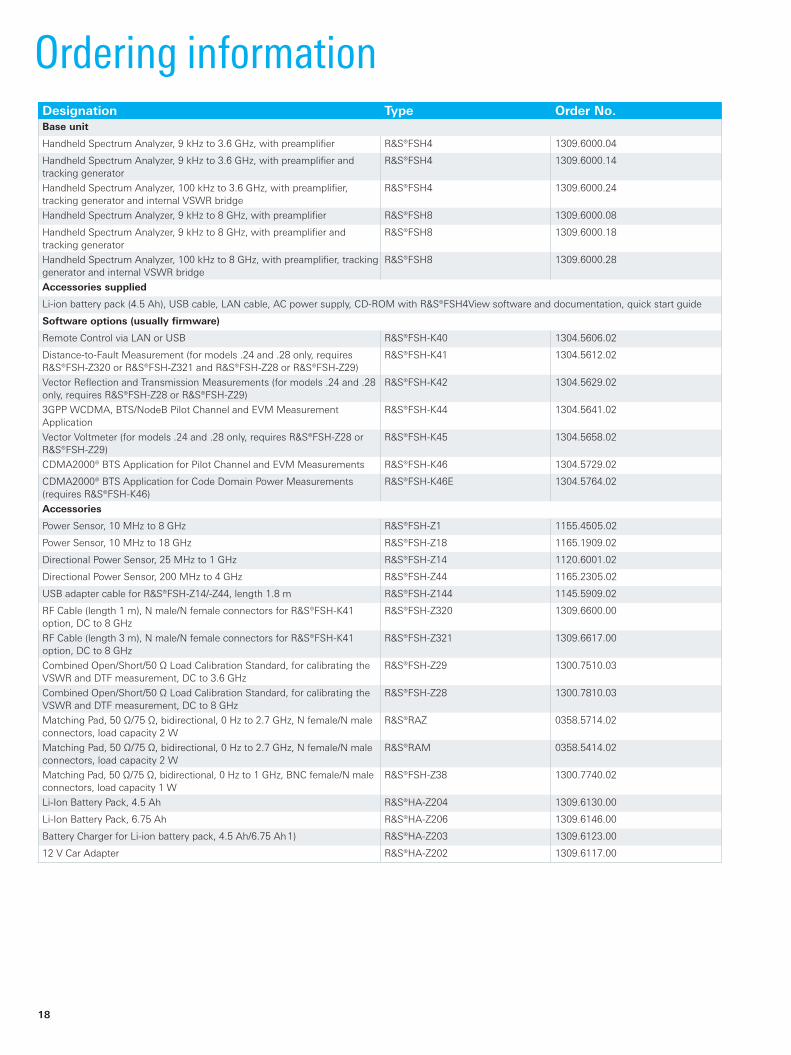
OrderinginformationDesignation Type Order No.Base unit
Handheld Spectrum Analyzer, 9 kHz to 3.6 GHz, with preamplifier R&S®FSH4 1309.6000.04
Handheld Spectrum Analyzer, 9 kHz to 3.6 GHz, with preamplifier and tracking generator
R&S®FSH4 1309.6000.14
Handheld Spectrum Analyzer, 100 kHz to 3.6 GHz, with preamplifier, tracking generator and internal VSWR bridge
R&S®FSH4 1309.6000.24
Handheld Spectrum Analyzer, 9 kHz to 8 GHz, with preamplifier R&S®FSH8 1309.6000.08
Handheld Spectrum Analyzer, 9 kHz to 8 GHz, with preamplifier and tracking generator
R&S®FSH8 1309.6000.18
Handheld Spectrum Analyzer, 100 kHz to 8 GHz, with preamplifier, tracking generator and internal VSWR bridge
R&S®FSH8 1309.6000.28
Accessories supplied
Li-ion battery pack (4.5 Ah), USB cable, LAN cable, AC power supply, CD-ROM with R&S®FSH4View software and documentation, quick start guide
Software options (usually firmware)
Remote Control via LAN or USB R&S®FSH-K40 1304.5606.02
Distance-to-Fault Measurement (for models .24 and .28 only, requires R&S®FSH-Z320 or R&S®FSH-Z321 and R&S®FSH-Z28 or R&S®FSH-Z29)
R&S®FSH-K41 1304.5612.02
Vector Reflection and Transmission Measurements (for models .24 and .28 only, requires R&S®FSH-Z28 or R&S®FSH-Z29)
R&S®FSH-K42 1304.5629.02
3GPP WCDMA, BTS/NodeB Pilot Channel and EVM Measurement Application
R&S®FSH-K44 1304.5641.02
Vector Voltmeter (for models .24 and .28 only, requires R&S®FSH-Z28 or R&S®FSH-Z29)
R&S®FSH-K45 1304.5658.02
CDMA2000® BTS Application for Pilot Channel and EVM Measurements R&S®FSH-K46 1304.5729.02
CDMA2000® BTS Application for Code Domain Power Measurements (requires R&S®FSH-K46)
R&S®FSH-K46E 1304.5764.02
Accessories
Power Sensor, 10 MHz to 8 GHz R&S®FSH-Z1 1155.4505.02
Power Sensor, 10 MHz to 18 GHz R&S®FSH-Z18 1165.1909.02
Directional Power Sensor, 25 MHz to 1 GHz R&S®FSH-Z14 1120.6001.02
Directional Power Sensor, 200 MHz to 4 GHz R&S®FSH-Z44 1165.2305.02
USB adapter cable for R&S®FSH-Z14/-Z44, length 1.8 m R&S®FSH-Z144 1145.5909.02
RF Cable (length 1 m), N male/N female connectors for R&S®FSH-K41 option, DC to 8 GHz
R&S®FSH-Z320 1309.6600.00
RF Cable (length 3 m), N male/N female connectors for R&S®FSH-K41 option, DC to 8 GHz
R&S®FSH-Z321 1309.6617.00
Combined Open/Short/50 Ω Load Calibration Standard, for calibrating the VSWR and DTF measurement, DC to 3.6 GHz
R&S®FSH-Z29 1300.7510.03
Combined Open/Short/50 Ω Load Calibration Standard, for calibrating the VSWR and DTF measurement, DC to 8 GHz
R&S®FSH-Z28 1300.7810.03
Matching Pad, 50 Ω/75 Ω, bidirectional, 0 Hz to 2.7 GHz, N female/N male connectors, load capacity 2 W
R&S®RAZ 0358.5714.02
Matching Pad, 50 Ω/75 Ω, bidirectional, 0 Hz to 2.7 GHz, N female/N male connectors, load capacity 2 W
R&S®RAM 0358.5414.02
Matching Pad, 50 Ω/75 Ω, bidirectional, 0 Hz to 1 GHz, BNC female/N male connectors, load capacity 1 W
R&S®FSH-Z38 1300.7740.02
Li-Ion Battery Pack, 4.5 Ah R&S®HA-Z204 1309.6130.00
Li-Ion Battery Pack, 6.75 Ah R&S®HA-Z206 1309.6146.00
Battery Charger for Li-ion battery pack, 4.5 Ah/6.75 Ah 1) R&S®HA-Z203 1309.6123.00
12 V Car Adapter R&S®HA-Z202 1309.6117.00
Rohde & Schwarz R&S®FSH4/FSH8 Handheld Spectrum Analyzer 19
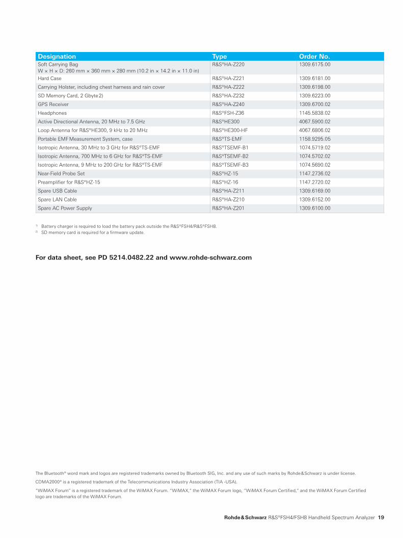
Designation Type Order No.Soft Carrying Bag W × H × D: 260 mm × 360 mm × 280 mm (10.2 in × 14.2 in × 11.0 in)
R&S®HA-Z220 1309.6175.00
Hard Case R&S®HA-Z221 1309.6181.00
Carrying Holster, including chest harness and rain cover R&S®HA-Z222 1309.6198.00
SD Memory Card, 2 Gbyte 2) R&S®HA-Z232 1309.6223.00
GPS Receiver R&S®HA-Z240 1309.6700.02
Headphones R&S®FSH-Z36 1145.5838.02
Active Directional Antenna, 20 MHz to 7.5 GHz R&S®HE300 4067.5900.02
Loop Antenna for R&S®HE300, 9 kHz to 20 MHz R&S®HE300-HF 4067.6806.02
Portable EMF Measurement System, case R&S®TS-EMF 1158.9295.05
Isotropic Antenna, 30 MHz to 3 GHz for R&S®TS-EMF R&S®TSEMF-B1 1074.5719.02
Isotropic Antenna, 700 MHz to 6 GHz for R&S®TS-EMF R&S®TSEMF-B2 1074.5702.02
Isotropic Antenna, 9 MHz to 200 GHz for R&S®TS-EMF R&S®TSEMF-B3 1074.5690.02
Near-Field Probe Set R&S®HZ-15 1147.2736.02
Preamplifier for R&S®HZ-15 R&S®HZ-16 1147.2720.02
Spare USB Cable R&S®HA-Z211 1309.6169.00
Spare LAN Cable R&S®HA-Z210 1309.6152.00
Spare AC Power Supply R&S®HA-Z201 1309.6100.00
1) Battery charger is required to load the battery pack outside the R&S®FSH4/R&S®FSH8.2) SD memory card is required for a firmware update.
For data sheet, see PD 5214.0482.22 and www.rohde-schwarz.com
The Bluetooth® word mark and logos are registered trademarks owned by Bluetooth SIG, Inc. and any use of such marks by Rohde & Schwarz is under license.
CDMA2000® is a registered trademark of the Telecommunications Industry Association (TIA -USA).
“WiMAX Forum“ is a registered trademark of the WiMAX Forum. “WiMAX,“ the WiMAX Forum logo, “WiMAX Forum Certified,“ and the WiMAX Forum Certified logo are trademarks of the WiMAX Forum.

R&S® is a registered trademark of Rohde & Schwarz GmbH & Co. KG
Trade names are trademarks of the owners | Printed in Germany (as)
PD 5214.0482.12 | Version 03.00 | April 2010 | R&S®FSH4/FSH8
Data without tolerance limits is not binding | Subject to change
© 2008 - 2010 Rohde & Schwarz GmbH Co. KG | 81671 München, Germany
About Rohde & SchwarzRohde & Schwarz is an independent group of companies specializing in electronics. It is a leading supplier of solu-tions in the fields of test and measurement, broadcast-ing, radiomonitoring and radiolocation, as well as secure communications. Established more than 75 years ago, Rohde & Schwarz has a global presence and a dedicated service network in over 70 countries. Company headquar-ters are in Munich, Germany.
Environmental commitment ❙ Energy-efficient products ❙ Continuous improvement in environmental sustainability ❙ ISO 14001-certified environmental management system
CertifiedQualitySystem
ISO9001
Rohde & Schwarz GmbH & Co. KGwww.rohde-schwarz.com
Regional contact ❙ Europe, Africa, Middle East +49 89 4129 137 74 [email protected]
❙ North America 1 888 TEST RSA (1 888 837 87 72) [email protected]
❙ Latin America +1 410 910 79 88 [email protected]
❙ Asia/Pacific +65 65 13 04 88 [email protected]
Service you can rely onJ Worldwide J Local and personalizedJ Customized and flexibleJ Uncompromising qualityJ Long-term dependability
![CDMA JULIO [Modo de compatibilidad] - Ivan Bernalclusterfie.epn.edu.ec/.../ComInalam/ClasesNuevas/CDMA_JULIO.pdf · 4 Introducción • cdmaOne: denota la familia de tecnologías](https://img.dokumen.tips/doc/110x75/5b202b047f8b9ad34c8b5327/cdma-julio-modo-de-compatibilidad-ivan-4-introduccion-cdmaone-denota.jpg)


![St. Xavier’s College – Autonomous Mumbai Syllabus For … schemes [TDMA, FDMA, CDMA] Separating uplink and downlink traffic GSM migration PDC migration Cdmaone migration M-Commerce](https://img.dokumen.tips/doc/110x75/5b3a8b1d7f8b9a1a678dbe06/st-xaviers-college-autonomous-mumbai-syllabus-for-schemes-tdma-fdma-cdma.jpg)


![R&S FSH4/8 G]G GWGfGyGWG GGGhG=GVGwGnG G0GXGwG2GD …](https://img.dokumen.tips/doc/110x75/61bd4af161276e740b115a81/ramps-fsh48-gg-gwgfgygwg-ggghggvgwgng-g0gxgwg2gd-.jpg)