Embed Size (px)
Citation preview
ROSS CONTROLS®
www.rosscontrols.com
RSe SeRieS 5/2 Safe CylindeR RetuRn double ValVeS
integRation guide
2 © 2019, ROSS CONTROLS®. All Rights Reserved.
5/2 RSe Series Valves Integration Guide
Table of Contents
Integration Guide – 5/2 RSe Series Safe Cylinder Return Valves
Page
General Information
Introduction
3Pulse Testing
Considerations for Safe Distance Calculations
RSe Wiring (Pinouts)
Pilot Supply Conversion 4 - 5
Operation & Monitoring Requirements for 5/2 RSe Series Valves5
Valve Operation
Feedback Monitoring (General)6
Actuation Fault Monitoring
De-Actuation Fault Monitoring
7Loss of Supply Pressure While Actuated
No Supply Pressure Applied Before Actuation
Valve Fault & Safety System Reset
RSe (5/2) Validation Test Procedure for Valve Operation and External Monitoring Logic 8 - 10
Cautions, Warnings and Standard WarrantyCover
Global Locations
www.rosscontrols.com 3
5/2 RSe Series Valves Integration Guide
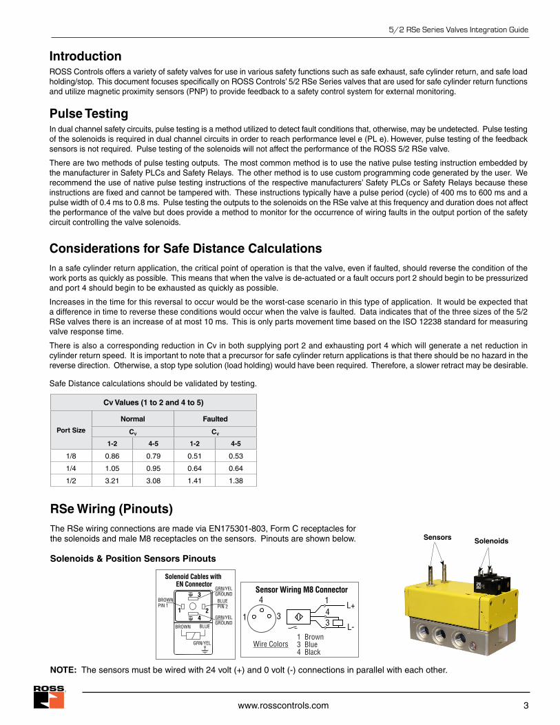
Introduction ROSS Controls offers a variety of safety valves for use in various safety functions such as safe exhaust, safe cylinder return, and safe load holding/stop. This document focuses specifically on ROSS Controls’ 5/2 RSe Series valves that are used for safe cylinder return functions and utilize magnetic proximity sensors (PNP) to provide feedback to a safety control system for external monitoring.
Pulse TestingIn dual channel safety circuits, pulse testing is a method utilized to detect fault conditions that, otherwise, may be undetected. Pulse testing of the solenoids is required in dual channel circuits in order to reach performance level e (PL e). However, pulse testing of the feedback sensors is not required. Pulse testing of the solenoids will not affect the performance of the ROSS 5/2 RSe valve.
There are two methods of pulse testing outputs. The most common method is to use the native pulse testing instruction embedded by the manufacturer in Safety PLCs and Safety Relays. The other method is to use custom programming code generated by the user. We recommend the use of native pulse testing instructions of the respective manufacturers’ Safety PLCs or Safety Relays because these instructions are fixed and cannot be tampered with. These instructions typically have a pulse period (cycle) of 400 ms to 600 ms and a pulse width of 0.4 ms to 0.8 ms. Pulse testing the outputs to the solenoids on the RSe valve at this frequency and duration does not affect the performance of the valve but does provide a method to monitor for the occurrence of wiring faults in the output portion of the safety circuit controlling the valve solenoids.
Considerations for Safe Distance CalculationsIn a safe cylinder return application, the critical point of operation is that the valve, even if faulted, should reverse the condition of the work ports as quickly as possible. This means that when the valve is de-actuated or a fault occurs port 2 should begin to be pressurized and port 4 should begin to be exhausted as quickly as possible.
Increases in the time for this reversal to occur would be the worst-case scenario in this type of application. It would be expected that a difference in time to reverse these conditions would occur when the valve is faulted. Data indicates that of the three sizes of the 5/2 RSe valves there is an increase of at most 10 ms. This is only parts movement time based on the ISO 12238 standard for measuring valve response time.
There is also a corresponding reduction in Cv in both supplying port 2 and exhausting port 4 which will generate a net reduction in cylinder return speed. It is important to note that a precursor for safe cylinder return applications is that there should be no hazard in the reverse direction. Otherwise, a stop type solution (load holding) would have been required. Therefore, a slower retract may be desirable.
Safe Distance calculations should be validated by testing.
Cv Values (1 to 2 and 4 to 5)
Port Size
Normal Faulted
CV CV
1-2 4-5 1-2 4-5
1/8 0.86 0.79 0.51 0.53
1/4 1.05 0.95 0.64 0.64
1/2 3.21 3.08 1.41 1.38
RSe Wiring (Pinouts)The RSe wiring connections are made via EN175301-803, Form C receptacles for the solenoids and male M8 receptacles on the sensors. Pinouts are shown below.
Solenoids & Position Sensors Pinouts
NOTE: The sensors must be wired with 24 volt (+) and 0 volt (-) connections in parallel with each other.
GRN/YELGROUND
BROWN BLUE
GRN/YEL
Solenoid Cables with EN Connector
GRN/YELGROUND3
214
BLUEPIN 2
BROWNPIN 1
Sensor Wiring M8 Connector
1 3
4 1
34
L+
L-1 Brown3 Blue4 Black
Wire Colors
SolenoidsSensors
4 © 2019, ROSS CONTROLS®. All Rights Reserved.
5/2 RSe Series Valves Integration Guide
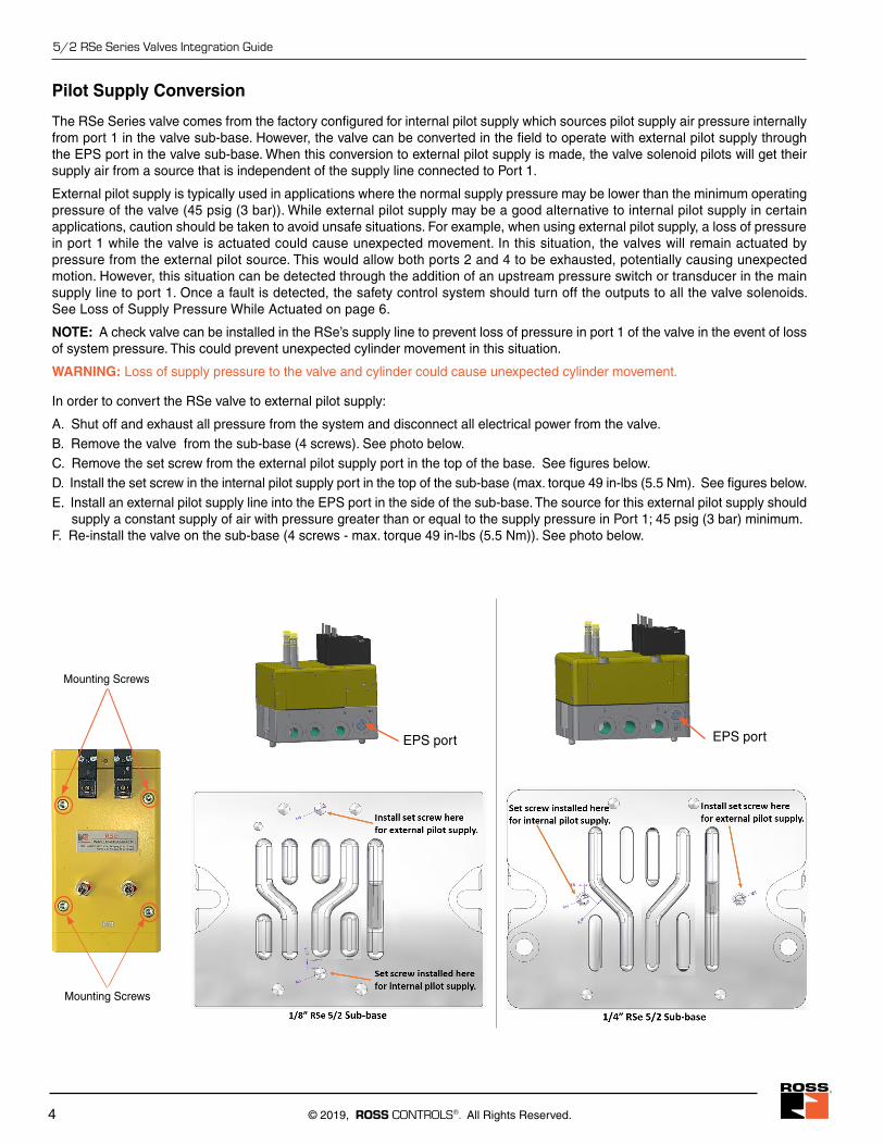
Pilot Supply Conversion
The RSe Series valve comes from the factory configured for internal pilot supply which sources pilot supply air pressure internally from port 1 in the valve sub-base. However, the valve can be converted in the field to operate with external pilot supply through the EPS port in the valve sub-base. When this conversion to external pilot supply is made, the valve solenoid pilots will get their supply air from a source that is independent of the supply line connected to Port 1.
External pilot supply is typically used in applications where the normal supply pressure may be lower than the minimum operating pressure of the valve (45 psig (3 bar)). While external pilot supply may be a good alternative to internal pilot supply in certain applications, caution should be taken to avoid unsafe situations. For example, when using external pilot supply, a loss of pressure in port 1 while the valve is actuated could cause unexpected movement. In this situation, the valves will remain actuated by pressure from the external pilot source. This would allow both ports 2 and 4 to be exhausted, potentially causing unexpected motion. However, this situation can be detected through the addition of an upstream pressure switch or transducer in the main supply line to port 1. Once a fault is detected, the safety control system should turn off the outputs to all the valve solenoids. See Loss of Supply Pressure While Actuated on page 6.
NOTE: A check valve can be installed in the RSe’s supply line to prevent loss of pressure in port 1 of the valve in the event of loss of system pressure. This could prevent unexpected cylinder movement in this situation.
WARNING: Loss of supply pressure to the valve and cylinder could cause unexpected cylinder movement.
In order to convert the RSe valve to external pilot supply:
A. Shut off and exhaust all pressure from the system and disconnect all electrical power from the valve.B. Remove the valve from the sub-base (4 screws). See photo below. C. Remove the set screw from the external pilot supply port in the top of the base. See figures below.D. Install the set screw in the internal pilot supply port in the top of the sub-base (max. torque 49 in-lbs (5.5 Nm). See figures below.E. Install an external pilot supply line into the EPS port in the side of the sub-base. The source for this external pilot supply should supply a constant supply of air with pressure greater than or equal to the supply pressure in Port 1; 45 psig (3 bar) minimum.F. Re-install the valve on the sub-base (4 screws - max. torque 49 in-lbs (5.5 Nm)). See photo below.
EPS portEPS port
Mounting Screws
Mounting Screws
www.rosscontrols.com 5
5/2 RSe Series Valves Integration Guide
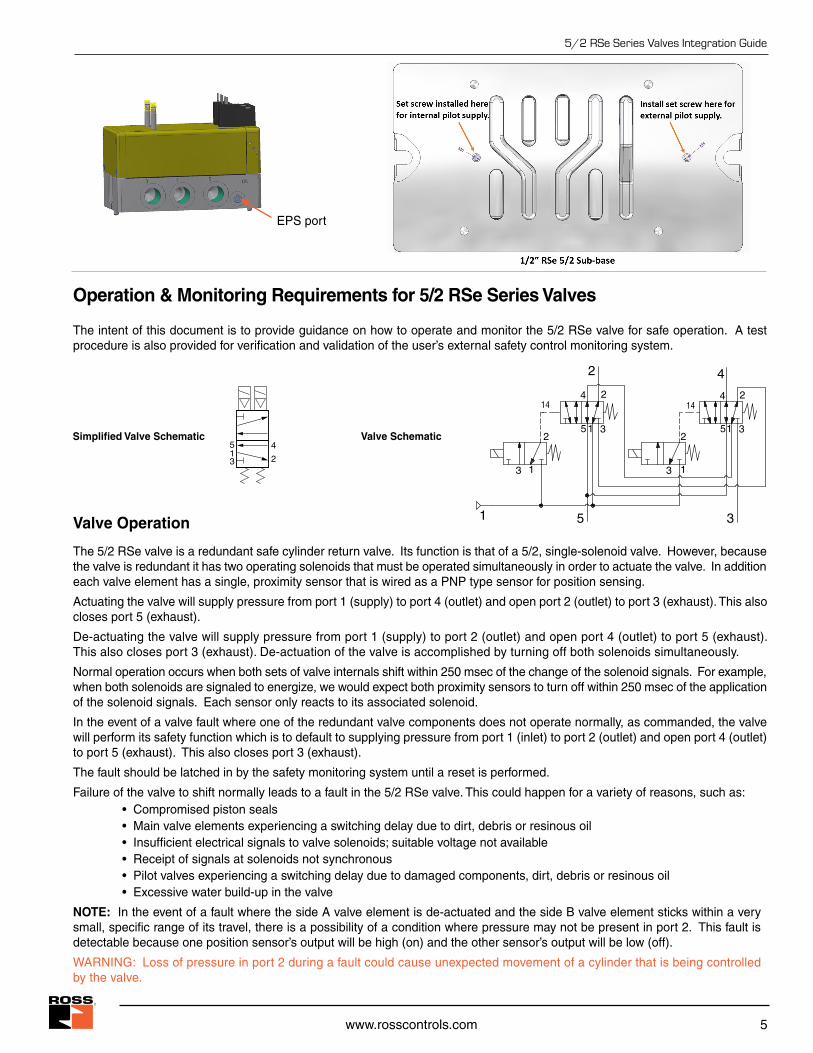
Operation & Monitoring Requirements for 5/2 RSe Series Valves
The intent of this document is to provide guidance on how to operate and monitor the 5/2 RSe valve for safe operation. A test procedure is also provided for verification and validation of the user’s external safety control monitoring system.
Valve Operation
The 5/2 RSe valve is a redundant safe cylinder return valve. Its function is that of a 5/2, single-solenoid valve. However, because the valve is redundant it has two operating solenoids that must be operated simultaneously in order to actuate the valve. In addition each valve element has a single, proximity sensor that is wired as a PNP type sensor for position sensing.
Actuating the valve will supply pressure from port 1 (supply) to port 4 (outlet) and open port 2 (outlet) to port 3 (exhaust). This also closes port 5 (exhaust).
De-actuating the valve will supply pressure from port 1 (supply) to port 2 (outlet) and open port 4 (outlet) to port 5 (exhaust). This also closes port 3 (exhaust). De-actuation of the valve is accomplished by turning off both solenoids simultaneously.
Normal operation occurs when both sets of valve internals shift within 250 msec of the change of the solenoid signals. For example, when both solenoids are signaled to energize, we would expect both proximity sensors to turn off within 250 msec of the application of the solenoid signals. Each sensor only reacts to its associated solenoid.
In the event of a valve fault where one of the redundant valve components does not operate normally, as commanded, the valve will perform its safety function which is to default to supplying pressure from port 1 (inlet) to port 2 (outlet) and open port 4 (outlet) to port 5 (exhaust). This also closes port 3 (exhaust).
The fault should be latched in by the safety monitoring system until a reset is performed.
Failure of the valve to shift normally leads to a fault in the 5/2 RSe valve. This could happen for a variety of reasons, such as: • Compromised piston seals • Main valve elements experiencing a switching delay due to dirt, debris or resinous oil • Insufficient electrical signals to valve solenoids; suitable voltage not available • Receipt of signals at solenoids not synchronous • Pilot valves experiencing a switching delay due to damaged components, dirt, debris or resinous oil • Excessive water build-up in the valve
NOTE: In the event of a fault where the side A valve element is de-actuated and the side B valve element sticks within a very small, specific range of its travel, there is a possibility of a condition where pressure may not be present in port 2. This fault is detectable because one position sensor’s output will be high (on) and the other sensor’s output will be low (off).
WARNING: Loss of pressure in port 2 during a fault could cause unexpected movement of a cylinder that is being controlled by the valve.
EPS port
2
413
5Simplified Valve Schematic Valve Schematic
2
4
51 3
2
2
13
4
51 3
2
2
13
4
35
14 14
1
6 © 2019, ROSS CONTROLS®. All Rights Reserved.
5/2 RSe Series Valves Integration Guide
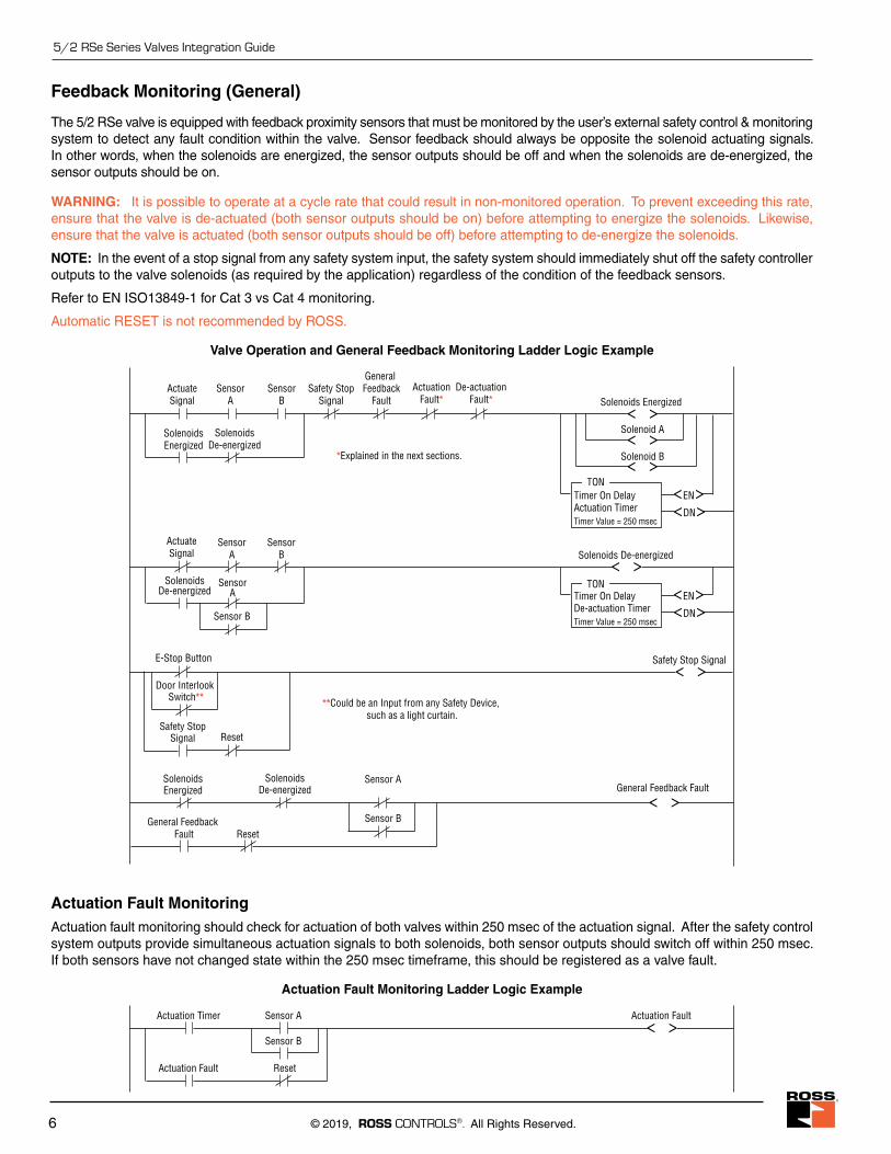
Feedback Monitoring (General)
The 5/2 RSe valve is equipped with feedback proximity sensors that must be monitored by the user’s external safety control & monitoring system to detect any fault condition within the valve. Sensor feedback should always be opposite the solenoid actuating signals. In other words, when the solenoids are energized, the sensor outputs should be off and when the solenoids are de-energized, the sensor outputs should be on.
WARNING: It is possible to operate at a cycle rate that could result in non-monitored operation. To prevent exceeding this rate, ensure that the valve is de-actuated (both sensor outputs should be on) before attempting to energize the solenoids. Likewise, ensure that the valve is actuated (both sensor outputs should be off) before attempting to de-energize the solenoids.
NOTE: In the event of a stop signal from any safety system input, the safety system should immediately shut off the safety controller outputs to the valve solenoids (as required by the application) regardless of the condition of the feedback sensors.
Refer to EN ISO13849-1 for Cat 3 vs Cat 4 monitoring.
Automatic RESET is not recommended by ROSS.
Valve Operation and General Feedback Monitoring Ladder Logic Example
ActuateSignal
SensorA
SensorB
Safety StopSignal
General Feedback
Fault Solenoids Energized
Solenoid ASolenoidsEnergized
SolenoidsDe-energized
SensorB
SensorA
ActuateSignal
< >< >< >
Solenoid B
< >Solenoids De-energized
De-actuationFault*
ActuationFault*
SolenoidsDe-energized
SensorA
EN< >< >DN
TON Timer On DelayActuation TimerTimer Value = 250 msec
EN< >< >DN
TON Timer On DelayDe-actuation TimerTimer Value = 250 msecSensor B
E-Stop Button Safety Stop Signal
Reset
Door Interlook Switch**
< >
Safety StopSignal
*Explained in the next sections.
**Could be an Input from any Safety Device, such as a light curtain.
Sensor ASolenoidsEnergized
SolenoidsDe-energized General Feedback Fault
Reset
< >General Feedback
FaultSensor B
Actuation Fault MonitoringActuation fault monitoring should check for actuation of both valves within 250 msec of the actuation signal. After the safety control system outputs provide simultaneous actuation signals to both solenoids, both sensor outputs should switch off within 250 msec. If both sensors have not changed state within the 250 msec timeframe, this should be registered as a valve fault.
Actuation Fault Monitoring Ladder Logic Example
Actuation Fault Reset
Sensor A< >
Sensor B
Actuation FaultActuation Timer
www.rosscontrols.com 7
5/2 RSe Series Valves Integration Guide
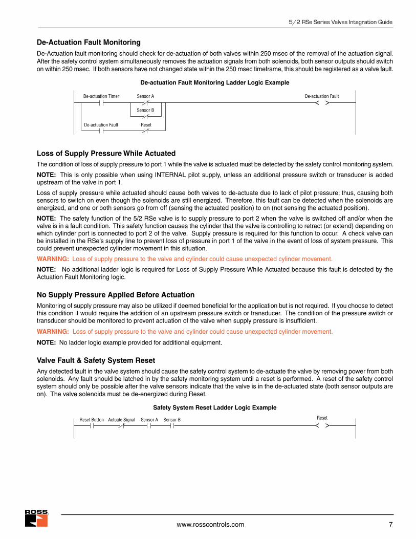
De-Actuation Fault MonitoringDe-Actuation fault monitoring should check for de-actuation of both valves within 250 msec of the removal of the actuation signal. After the safety control system simultaneously removes the actuation signals from both solenoids, both sensor outputs should switch on within 250 msec. If both sensors have not changed state within the 250 msec timeframe, this should be registered as a valve fault.
De-actuation Fault Monitoring Ladder Logic Example
De-actuation Fault Reset
Sensor A< >
Sensor B
De-actuation FaultDe-actuation Timer
Loss of Supply Pressure While ActuatedThe condition of loss of supply pressure to port 1 while the valve is actuated must be detected by the safety control monitoring system.
NOTE: This is only possible when using INTERNAL pilot supply, unless an additional pressure switch or transducer is added upstream of the valve in port 1.
Loss of supply pressure while actuated should cause both valves to de-actuate due to lack of pilot pressure; thus, causing both sensors to switch on even though the solenoids are still energized. Therefore, this fault can be detected when the solenoids are energized, and one or both sensors go from off (sensing the actuated position) to on (not sensing the actuated position).
NOTE: The safety function of the 5/2 RSe valve is to supply pressure to port 2 when the valve is switched off and/or when the valve is in a fault condition. This safety function causes the cylinder that the valve is controlling to retract (or extend) depending on which cylinder port is connected to port 2 of the valve. Supply pressure is required for this function to occur. A check valve can be installed in the RSe’s supply line to prevent loss of pressure in port 1 of the valve in the event of loss of system pressure. This could prevent unexpected cylinder movement in this situation.
WARNING: Loss of supply pressure to the valve and cylinder could cause unexpected cylinder movement.
NOTE: No additional ladder logic is required for Loss of Supply Pressure While Actuated because this fault is detected by the Actuation Fault Monitoring logic.
No Supply Pressure Applied Before ActuationMonitoring of supply pressure may also be utilized if deemed beneficial for the application but is not required. If you choose to detect this condition it would require the addition of an upstream pressure switch or transducer. The condition of the pressure switch or transducer should be monitored to prevent actuation of the valve when supply pressure is insufficient.
WARNING: Loss of supply pressure to the valve and cylinder could cause unexpected cylinder movement.
NOTE: No ladder logic example provided for additional equipment.
Valve Fault & Safety System ResetAny detected fault in the valve system should cause the safety control system to de-actuate the valve by removing power from both solenoids. Any fault should be latched in by the safety monitoring system until a reset is performed. A reset of the safety control system should only be possible after the valve sensors indicate that the valve is in the de-actuated state (both sensor outputs are on). The valve solenoids must be de-energized during Reset.
Safety System Reset Ladder Logic Example
< >Reset Button Actuate Signal Sensor A Sensor B Reset
8 © 2019, ROSS CONTROLS®. All Rights Reserved.
5/2 RSe Series Valves Integration Guide
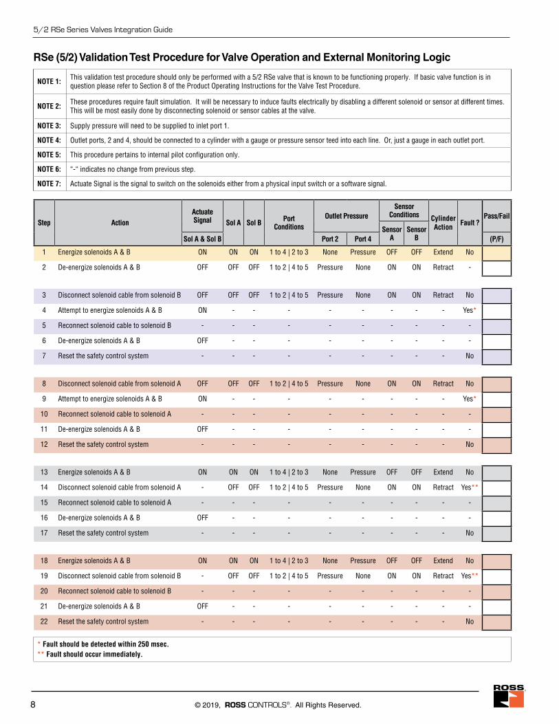
NOTE 1: This validation test procedure should only be performed with a 5/2 RSe valve that is known to be functioning properly. If basic valve function is in question please refer to Section 8 of the Product Operating Instructions for the Valve Test Procedure.
NOTE 2: These procedures require fault simulation. It will be necessary to induce faults electrically by disabling a different solenoid or sensor at different times. This will be most easily done by disconnecting solenoid or sensor cables at the valve.
NOTE 3: Supply pressure will need to be supplied to inlet port 1.
NOTE 4: Outlet ports, 2 and 4, should be connected to a cylinder with a gauge or pressure sensor teed into each line. Or, just a gauge in each outlet port.
NOTE 5: This procedure pertains to internal pilot configuration only.
NOTE 6: “-“ indicates no change from previous step.
NOTE 7: Actuate Signal is the signal to switch on the solenoids either from a physical input switch or a software signal.
RSe (5/2) Validation Test Procedure for Valve Operation and External Monitoring Logic
Step ActionActuate Signal Sol A Sol B Port
ConditionsOutlet Pressure
Sensor Conditions Cylinder
Action Fault ?Pass/Fail
Sensor A
Sensor BSol A & Sol B Port 2 Port 4 (P/F)
1 Energize solenoids A & B ON ON ON 1 to 4 | 2 to 3 None Pressure OFF OFF Extend No
2 De-energize solenoids A & B OFF OFF OFF 1 to 2 | 4 to 5 Pressure None ON ON Retract -
3 Disconnect solenoid cable from solenoid B OFF OFF OFF 1 to 2 | 4 to 5 Pressure None ON ON Retract No
4 Attempt to energize solenoids A & B ON - - - - - - - - Yes*
5 Reconnect solenoid cable to solenoid B - - - - - - - - - -
6 De-energize solenoids A & B OFF - - - - - - - - -
7 Reset the safety control system - - - - - - - - - No
8 Disconnect solenoid cable from solenoid A OFF OFF OFF 1 to 2 | 4 to 5 Pressure None ON ON Retract No
9 Attempt to energize solenoids A & B ON - - - - - - - - Yes*
10 Reconnect solenoid cable to solenoid A - - - - - - - - - -
11 De-energize solenoids A & B OFF - - - - - - - - -
12 Reset the safety control system - - - - - - - - - No
13 Energize solenoids A & B ON ON ON 1 to 4 | 2 to 3 None Pressure OFF OFF Extend No
14 Disconnect solenoid cable from solenoid A - OFF OFF 1 to 2 | 4 to 5 Pressure None ON ON Retract Yes**
15 Reconnect solenoid cable to solenoid A - - - - - - - - - -
16 De-energize solenoids A & B OFF - - - - - - - - -
17 Reset the safety control system - - - - - - - - - No
18 Energize solenoids A & B ON ON ON 1 to 4 | 2 to 3 None Pressure OFF OFF Extend No
19 Disconnect solenoid cable from solenoid B - OFF OFF 1 to 2 | 4 to 5 Pressure None ON ON Retract Yes**
20 Reconnect solenoid cable to solenoid B - - - - - - - - - -
21 De-energize solenoids A & B OFF - - - - - - - - -
22 Reset the safety control system - - - - - - - - - No
* Fault should be detected within 250 msec. ** Fault should occur immediately.
www.rosscontrols.com 9
5/2 RSe Series Valves Integration Guide
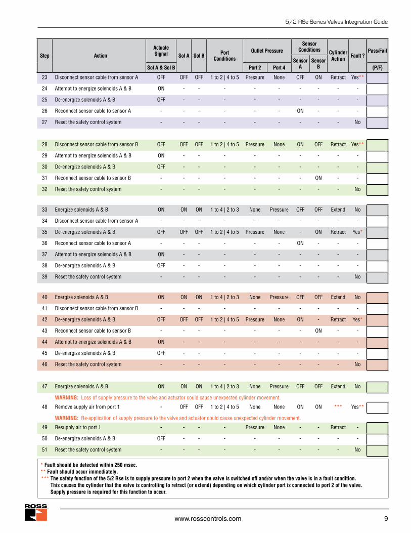
23 Disconnect sensor cable from sensor A OFF OFF OFF 1 to 2 | 4 to 5 Pressure None OFF ON Retract Yes**
24 Attempt to energize solenoids A & B ON - - - - - - - - -
25 De-energize solenoids A & B OFF - - - - - - - - -
26 Reconnect sensor cable to sensor A - - - - - - ON - - -
27 Reset the safety control system - - - - - - - - - No
28 Disconnect sensor cable from sensor B OFF OFF OFF 1 to 2 | 4 to 5 Pressure None ON OFF Retract Yes**
29 Attempt to energize solenoids A & B ON - - - - - - - - -
30 De-energize solenoids A & B OFF - - - - - - - - -
31 Reconnect sensor cable to sensor B - - - - - - - ON - -
32 Reset the safety control system - - - - - - - - - No
33 Energize solenoids A & B ON ON ON 1 to 4 | 2 to 3 None Pressure OFF OFF Extend No
34 Disconnect sensor cable from sensor A - - - - - - - - - -
35 De-energize solenoids A & B OFF OFF OFF 1 to 2 | 4 to 5 Pressure None - ON Retract Yes*
36 Reconnect sensor cable to sensor A - - - - - - ON - - -
37 Attempt to energize solenoids A & B ON - - - - - - - - -
38 De-energize solenoids A & B OFF - - - - - - - - -
39 Reset the safety control system - - - - - - - - - No
40 Energize solenoids A & B ON ON ON 1 to 4 | 2 to 3 None Pressure OFF OFF Extend No
41 Disconnect sensor cable from sensor B - - - - - - - - - -
42 De-energize solenoids A & B OFF OFF OFF 1 to 2 | 4 to 5 Pressure None ON - Retract Yes*
43 Reconnect sensor cable to sensor B - - - - - - - ON - -
44 Attempt to energize solenoids A & B ON - - - - - - - - -
45 De-energize solenoids A & B OFF - - - - - - - - -
46 Reset the safety control system - - - - - - - - - No
47 Energize solenoids A & B ON ON ON 1 to 4 | 2 to 3 None Pressure OFF OFF Extend No
WARNING: Loss of supply pressure to the valve and actuator could cause unexpected cylinder movement.
48 Remove supply air from port 1 - OFF OFF 1 to 2 | 4 to 5 None None ON ON *** Yes**
WARNING: Re-application of supply pressure to the valve and actuator could cause unexpected cylinder movement.
49 Resupply air to port 1 - - - - Pressure None - - Retract -
50 De-energize solenoids A & B OFF - - - - - - - - -
51 Reset the safety control system - - - - - - - - - No
* Fault should be detected within 250 msec. ** Fault should occur immediately.*** The safety function of the 5/2 Rse is to supply pressure to port 2 when the valve is switched off and/or when the valve is in a fault condition.
This causes the cylinder that the valve is controlling to retract (or extend) depending on which cylinder port is connected to port 2 of the valve. Supply pressure is required for this function to occur.
Step ActionActuate Signal Sol A Sol B Port
ConditionsOutlet Pressure
Sensor Conditions Cylinder
Action Fault ?Pass/Fail
Sensor A
Sensor BSol A & Sol B Port 2 Port 4 (P/F)
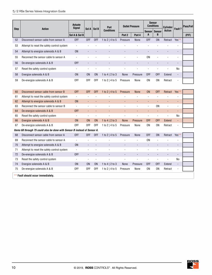
10 © 2019, ROSS CONTROLS®. All Rights Reserved.
5/2 RSe Series Valves Integration Guide
52 Disconnect sensor cable from sensor A OFF OFF OFF 1 to 2 | 4 to 5 Pressure None OFF ON Retract Yes**
53 Attempt to reset the safety control system - - - - - - - - - -
54 Attempt to energize solenoids A & B ON - - - - - - - - -
55 Reconnect the sensor cable to sensor A - - - - - - ON - - -
56 De-energize solenoids A & B OFF - - - - - - - - -
57 Reset the safety control system - - - - - - - - - No
58 Energize solenoids A & B ON ON ON 1 to 4 | 2 to 3 None Pressure OFF OFF Extend -
59 De-energize solenoids A & B OFF OFF OFF 1 to 2 | 4 to 5 Pressure None ON ON Retract -
60 Disconnect sensor cable from sensor B OFF OFF OFF 1 to 2 | 4 to 5 Pressure None ON OFF Retract Yes**
61 Attempt to reset the safety control system - - - - - - - - - -
62 Attempt to energize solenoids A & B ON - - - - - - - - -
63 Reconnect the sensor cable to sensor B - - - - - - - ON - -
64 De-energize solenoids A & B OFF - - - - - - - - -
65 Reset the safety control system - - - - - - - - - No
66 Energize solenoids A & B ON ON ON 1 to 4 | 2 to 3 None Pressure OFF OFF Extend -
67 De-energize solenoids A & B OFF OFF OFF 1 to 2 | 4 to 5 Pressure None ON ON Retract -
Items 68 through 75 could also be done with Sensor B instead of Sensor A.
68 Disconnect sensor cable from sensor A OFF OFF OFF 1 to 2 | 4 to 5 Pressure None OFF ON Retract Yes**
69 Reconnect the sensor cable to sensor A - - - - - - ON - - -
70 Attempt to energize solenoids A & B ON - - - - - - - - -
71 Attempt to reset the safety control system - - - - - - - - - -
72 De-energize solenoids A & B OFF - - - - - - - - -
73 Reset the safety control system - - - - - - - - - No
74 Energize solenoids A & B ON ON ON 1 to 4 | 2 to 3 None Pressure OFF OFF Extend -
75 De-energize solenoids A & B OFF OFF OFF 1 to 2 | 4 to 5 Pressure None ON ON Retract -
** Fault should occur immediately.
Step ActionActuate Signal Sol A Sol B Port
ConditionsOutlet Pressure
Sensor Conditions Cylinder
Action Fault ?Pass/Fail
Sensor A
Sensor BSol A & Sol B Port 2 Port 4 (P/F)
www.rosscontrols.com 11
5/2 RSe Series Valves Integration Guide
CAUTIONS, WARNINGS AND STANDARD WARRANTY
PRE-INSTALLATION or SERVICE
1. Before servicing a valve or other pneumatic component, be sure all sources of energy are turned off, the entire pneumatic system is shut down and exhausted, and all power sources are locked out (ref: OSHA 1910.147, EN 1037).2. All ROSS Group Products, including service kits and parts, should be installed and/or serviced only by persons having training and experience with pneumatic equipment. Because any product can be tampered with and/or need servicing after installation, persons responsible for the safety of others or the care of equipment must check ROSS Group Products on a regular basis and perform all necessary maintenance to ensure safe operating conditions.3. All applicable instructions should be read and complied with before using any fluid power system to prevent harm to persons or equipment. In addition, overhauled or serviced valves must be functionally tested prior to installation and use. If you have any questions, call your nearest ROSS Group location.4. Each ROSS Group Product should be used within its specification limits. In addition, use only ROSS Group components to repair ROSS Group Products.
WARNINGS: Failure to follow these instructions can result in personal injury and/or property damage.
FILTRATION and LUBRICATION
1. Dirt, scale, moisture, etc., are present in virtually every air system. Although some valves are more tolerant of these contaminants than others, best performance will be realized if a filter is installed to clean the air supply, thus preventing contaminants from interfering with the proper performance of the equipment. The ROSS Group recommends a filter with a 5-micron rating for normal applications.2. All standard ROSS Group filters and lubricators with polycarbonate plastic bowls are designed for compressed air applications only. Use the metal bowl guard, where provided, to minimize danger from high pressure fragmentation in the event of bowl failure. Do not expose these products to certain fluids, such as alcohol or liquefied petroleum gas, as they can cause bowls to rupture, creating a combustible condition and hazardous leakage. Immediately replace crazed, cracked, or deteriorated bowls.3. Only use lubricants which are compatible with materials used in the valves and other components in the system. Normally, compatible lubricants are petroleum base oils with oxidation inhibitors, an aniline
point between 180°F (82°C) and 220°F (104°C), and an ISO 32, or lighter, viscosity. Avoid oils with phosphate type additives which can harm polyurethane components, potentially leading to valve failure which risks personal injury, and/or damage to property.
WARNINGS: Failure to follow these instructions can result in personal injury and/or property damage.
AVOID INTAKE/EXHAUST RESTRICTION1. Do not restrict air flow in the supply line. To do so could reduce the pressure of the supply air below minimum requirements for the valve and thereby causing erratic action.2. Do not restrict a valve's exhaust port as this can adversely affect its operation. Exhaust silencers must be resistant to clogging and must have flow capacities at least as great as the exhaust capacities of the valves. Contamination of the silencer can result in reduced flow and increased back pressure.
WARNINGS: Failure to follow these instructions can result in personal injury and/or property damage.
SAFETY APPLICATIONS1. Mechanical Power Presses and other potentially hazardous machinery using a pneumatically controlled clutch and brake mechanism must use a press control double valve with a monitoring device. A double valve without a self-contained monitoring device should be used only in conjunction with a control system which assures monitoring of the valve. All double valve installations involving hazardous applications should incorporate a monitoring system which inhibits further operation of the valve and machine in the event of a failure within the valve mechanism.2. Safety exhaust (dump) valves without a self-contained monitoring device should be used only in conjunction with a control system which assures monitoring of the valve. All safety exhaust valve installations should incorporate a monitoring system which inhibits further operation of the valve and machine in the event of a failure within the valve mechanism.3. Per specifications and regulations, the ROSS L-O-X® and L-O-X® with EEZ-ON®, N06 and N16 Series operation products are defined as energy isolation devices, NOT AS EMERGENCY STOP DEVICES.WARNINGS: Failure to follow these instructions can result in
personal injury and/or property damage.
STANDARD WARRANTYAll products sold by the ROSS Group are warranted for a one-year period [with the exception of Filters, Regulators and Lubricators (“FRLs”) which are warranted for a period of seven (7) years] from the date of purchase. All products are, during their respective warranty periods,
warranted to be free of defects in material and workmanship. The ROSS Group’s obligation under this warranty is limited to repair, replacement or refund of the purchase price paid for products which the ROSS Group has determined, in its sole discretion, are defective. All warranties become void if a product has been subject to misuse, misapplication, improper maintenance, modification or tampering. Products for which warranty protection is sought must be returned to the ROSS Group freight prepaid.
THE WARRANTY EXPRESSED ABOVE IS IN LIEU OF AND EXCLUSIVE OF ALL OTHER WARRANTIES AND THE ROSS GROUP EXPRESSLY DISCLAIMS ALL OTHER WARRANTIES EITHER EXPRESSED OR IMPLIED WITH RESPECT TO MERCHANTABILITY OR FITNESS FOR A PARTICULAR PURPOSE. THE ROSS GROUP MAKES NO WARRANTY WITH RESPECT TO ITS PRODUCTS MEETING THE PROVISIONS OF ANY GOVERNMENTAL OCCUPATIONAL SAFETY AND/OR HEALTH LAWS OR REGULATIONS. IN NO EVENT IS THE ROSS GROUP LIABLE TO PURCHASER, USER, THEIR EMPLOYEES OR OTHERS FOR INCIDENTAL OR CONSEQUENTIAL DAMAGES WHICH MAY RESULT FROM A BREACH OF THE WARRANTY DESCRIBED ABOVE OR THE USE OR MISUSE OF THE PRODUCTS. NO STATEMENT OF ANY REPRESENTATIVE OR EMPLOYEE OF THE ROSS GROUP MAY EXTEND THE LIABILITY OF THE ROSS GROUP AS SET FORTH HEREIN.
ROSS OPERATING VALVE, ROSS CONTROLS®, ROSS DECCO®, and AUTOMATIC VALVE INDUSTRIAL,
collectively the “ROSS Group".
Printed in the U.S.A. – Rev. 07/24/19 © 2019 ROSS CONTROLS®. All Rights Reserved. Form RSe52-IGContent subject to change.
ROSS CONTROLS USA Tel: Tech. Svs. 1-888-TEK-ROSS / Cust. Svs. 1-800-GET-ROSS www.rosscontrols.com
ROSS EUROPA GmbH Germany Tel: 49-6103-7597-100 www.rosseuropa.com
ROSS ASIA K.K. Japan Tel: 81-42-778-7251 www.rossasia.co.jp
ROSS UK Ltd. UK Tel: 44-1543-671495 www.rossuk.co.uk
ROSS SOUTH AMERICA Ltda. Brazil Tel: 55-11-4335-2200 www.rosscontrols.com.br
ROSS CONTROLS INDIA Pvt. Ltd. India Tel: 91-44-2624-9040 www.rosscontrols.com
ROSS CONTROLS (CHINA) Ltd. China Tel: 86-21-6915-7961 www.rosscontrolschina.com
ROSS FRANCE S.A.S. France Tel: 33-1-49-45-65-65 www.rossfrance.com
ROSS CANADA Canada Tel: 1-416-251-7677 (416-251-ROSS) www.rosscanada.com (6077170 CANADA INC. An Independent RepResentatIve)


![INDEX PVC-U BALL VALVES BALL VALVES … · 135 ball valves vÁlvulas de bola 01 industrial series [std] series standard series connectit system e-qua series pn10 series uniblock series](https://img.dokumen.tips/doc/110x75/5bb23b8209d3f2e82b8c356e/index-pvc-u-ball-valves-ball-valves-135-ball-valves-valvulas-de-bola-01-industrial.jpg)