Embed Size (px)
Citation preview

SUPPLEMENTAL RESTRAINT SYSTEM–SUPPLEMENTAL RESTRAINT SYSTEM
RS–1
GENERAL DESCRIPTIONThe 1994 CAMRY is equipped with an SRS (Supplemental Restraint System) such as the
driver airbag and front passenger airbag. Failure to carry out service operations in the correctsequence could cause the SRS to unexpectedly deployed during servicing, possibly leadingto a serious accident. Further, if a mistake is made in servicing the supplemental restraintsystem, it is possible the SRS may fail to operate when required. Before performing servicing(including removal or installation of parts, inspection or replacement), be sure to read thefollowing items carefully, then follow the correct procedure described in the repair manual.
1. Malfunction symptoms of the supplemental restraint system are difficult to confirm, so thediagnostic trouble codes become the most important source of information when troubleshoot–ing. When troubleshooting the supplemental restraint system, always inspect the diagnostictrouble codes before disconnecting the battery (See page RS–61).
2. Work must be started after 90 seconds from the time the ignition switch turned to the ”LOCK”position and the negative (–) terminal cable is disconnected from the battery. (The supple–mental restraint system is equipped with a back–up power source so that if work is startedwithin 90 seconds of disconnecting the negative (–) terminal cable of the battery, the SRSmay be deployed.) When the negative (–) terminal cable is disconnected from the battery,memory of the clock and audio systems will be canceled. So before starting work, make arecord of the contents memorized by the audio memory system. When work is finished, resetthe audio systems as before and adjust the clock. To avoid erasing the memory of eachmemory system, never use a back–up power supply from outside the vehicle.
3. Even in cases of a minor collision where the SRS does not deploy, and the front airbag sensors,the steering wheel pad and front passenger airbag assembly should be inspected (See page RS–17, 29, 43 and 46).
4. Never use SRS parts from another vehicle. When replacing parts, replace them with new parts.5. Before repairs, remove the airbag sensor if shocks are likely to be applied to the sensors during
repairs.6. Never disassemble and repair the front airbag sensors, center airbag sensor assembly or steering
wheel pad or front passenger airbag assembly in order to reuse it.7. If the front airbag sensors, center airbag sensor assembly or steering wheel pad or front
passenger airbag assembly have been dropped, or if there are cracks, dents or dents or otherdefects in the case, bracket or connector, replace them with new ones.
8. Do not expose the front airbag sensors, center airbag sensor assembly, steering wheel pad andfront passenger airbag assembly directly to hot air or flames.
9. Use a volt/ohmmeter with high impedance (10 k/V minimum) of troubleshooting of theelectrical circuit.
10. Information labels are attached to the periphery of the SRS components. Follow the instructionson the notices.
11. After work on the supplemental restraint system is completed, perform the SRS warning lightcheck (See page RS–61).
12. If the vehicle is equipped with a mobile communication system, refer to the precaution in the INsection.
–SUPPLEMENTAL RESTRAINT SYSTEM GENERAL DESCRIPTIONRS–2

3. The front airbag sensor set bolts have been anti–rust treated.When the sensor is removed, always replace the set bolts with new ones.
4. The front airbag sensors is equipped with an electrical connection check mechanism. Be sure tolock this mechanism securely when connecting the connector.If the connector is not securely locked, a malfunction code will be detected by the diagnosissystem (See page RS–13).
SPIRAL CABLE (in COMBINATION SWITCH)The steering wheel must be fitted correctly to the steering column with the spiral cable at theneutral position, otherwise cable disconnection and other troubles may result. Refer to page RS–20 of this manual concerning correct steering wheel installation.
FRONT AIRBAG SENSOR
1. Never reuse the front airbag sensor involved in a collision when the airbag has deployed. (Replaceboth the left and right airbag sensors.)2. Install the front airbag sensor with the arrow on the sensor facing toward the front of the vehicle.
–SUPPLEMENTAL RESTRAINT SYSTEM GENERAL DESCRIPTIONRS–3

3. Grease should not be applied to the steering wheel pad and the pad should not be cleanedwith detergents of any kind.
4. Store the steering wheel pad where the ambient temperature below 93 C (200 F), withouthigh humidity and away from electrical noise.
5. When using electric welding, first disconnect the airbag connector (yellow color and 2 pins)installed on the glove compartment finish plate at the left side of the glove compartmentbefore starting work.
6. When disposing of a vehicle or the steering wheel pad alone, the airbag should be deployedusing an SST before disposal (See page RS–23). Perform the operation in a place away fromelectrical noise.
STEERING WHEEL PAD (with AIRBAG)
1. When removing the steering wheel pad or handling a new steering wheel pad, it should beplaced with the pad top surface facing up.In this case, the twin–lock type connector lock lever should be in the locked state and careshould be taken to place it so the connector will not be damaged. And do not store a steeringwheel pad on top of another one. (Storing the pad with its metallic surface up may lead to aserious accident if the airbag inflates for some reason.
2. Never measure the resistance of the airbag squib.(This may cause the airbag to deploy, which is very dangerous.)
–SUPPLEMENTAL RESTRAINT SYSTEM GENERAL DESCRIPTIONRS–4

3. Grease should not be applied to the front passenger airbag and the door should not be cleanedwith detergents of any kind.
4. Store the front passenger airbag assembly where the ambient temperature remains below93C (200F), without high humidity and away from electrical noise.
5. When using electric welding, first disconnect the airbag connector (yellow color and 2 pins)installed on the glove compartment finish plate at the left side of the glove compartmentbefore starting work.6. When disposing of a vehicle or the front passenger airbag assembly alone, the airbag shouldbe deployed using an SST before disposal (See page RS–36). Perform the operation in a placeaway from electrical noise.
FRONT PASSENGER AIRBAG ASSEMBLY1. Always store a removed or new front passenger airbag assembly with the airbag door facingup. Store the airbag assembly with the airbag door facing down could cause a seriousaccident if the airbag inflates.
2. Never measure the resistance of the airbag squib.(This may cause the airbag to deploy, which is very dangerous.)
–SUPPLEMENTAL RESTRAINT SYSTEM GENERAL DESCRIPTIONRS–5

CENTER AIRBAG SENSOR ASSEMBLY
1. Never. reuse the center airbag sensor assembly involved in a collision when the airbag hasdeployed.2. The connectors to the center airbag sensor assembly should be connected or disconnectedwith the sensor mounted on the floor. If the connectors are connected or disconnected whilethe center airbag sensor assembly is not mounted to the floor, it could cause undesiredignition of the supplemental restraint system.3. Work must be started after 90 seconds from the time the ignition switch is turned to ”LOCK”position and the negative (–) terminal cable is disconnected from the battery even justloosing the set bolts of center airbag sensor assembly.
WIRE HARNESS AND CONNECTOR
The SRS wire harness is integrated with the cowl wire harness assembly. The wires for the SRSwire harness are encased in a yellow corrugated tube. All the connectors for the system are alsoa standard yellow color. If the SRS wire harness becomes disconnected or the connectorbecomes broken due to an accident etc., repair or replace it as shown on page RS–49.
–SUPPLEMENTAL RESTRAINT SYSTEM GENERAL DESCRIPTIONRS–6

DESCRIPTIONThe SRS (Supplemental Restraint System), together with the seat belt, is designed to help protectthe driver. In a collision, the airbag sensor detect the shock, and if the front–to–rear shock isgreater than a specified value, an airbag stored in the steering wheel pad and front passengerairbag assembly are inflated instantaneously. These operation help to reduce the shock to thedriver and front passenger airbag assembly.
LOCATION OF COMPONENTS
–SUPPLEMENTAL RESTRAINT SYSTEM DESCRIPTIONRS–7

WIRING DIAGRAM
–SUPPLEMENTAL RESTRAINT SYSTEM DESCRIPTIONRS–8

CENTER AIRBAG SENSOR ASSEMBLYCONNECTORS
Electrical Connection Check Mechanism
Electrical Connection Check Mechanism
Squib(–) (Front Passenger)
Squib(+) (Front Passenger)
Power Source (AM2 Fuse)
Front Airbag Sensor LH(–)
Front Airbag Sensor RH(+)
Front Airbag Sensor RH(–)
Front Airbag Sensor LH(+)
Power Source (CIG Fuse)
SRS Warning Light
Squib(–) (Driver)
Squib(+) (Driver)
Connector
Terminal Name
Diagnosis
Symbol
Ground
Ground
No.
–SUPPLEMENTAL RESTRAINT SYSTEM DESCRIPTIONRS–9

OPERATIONFUNCTION OF COMPONENTS1. FRONT AIRBAG SENSORA front airbag sensor is mounted inside each of thefront fenders. The sensor unit is a mechanical type.When the sensor detects deceleration force above apredetermined limit in a collision, the contacts in thesensor make contact, sending a signal to the centerairbag sensor assembly. The sensor cannot be dis–assembled.2. SPIRAL CABLE (in COMBINATION SWITCH)A spiral cable is used as an electrical joint from thevehicle body side to the steering wheel.
5. SRS WARNING LIGHTThe SRS warning light is located on the combinationmeter. It goes on the alert the driver of trouble in thesystem when a malfunction is detected in the centerairbag sensor assembly self – diagnosis. In normaloperating condition when the ignition switch is turnedto the ACC or ON position, the light goes on for about6 seconds and then goes off.
4. FRONT PASSENGER AIRBAG ASSEMBLYThe inflater and bag of the supplemental restraintsystem are stored in the front passenger airbag as–sembly and cannot be disassernbled. The inflater con–tains a squib, igniter charge, gas generant, etc., andinflates the bag in case of a frontal collision.
3. STEERING WHEEL PAD (with AIRBAG)The inflater and bag of the supplemental restraintsystem are stored in the steering wheel pad andcannot be disassembled. The inflater contains a squib,ignite charge, gas generant, etc., and inflates the bagin case of a frontal collision.
–SUPPLEMENTAL RESTRAINT SYSTEM OPERATIONRS–10

6. CENTER AIRBAG SENSOR ASSEMBLYThe center airbag sensor assembly is mounted on thefloor inside the console box. The center airbag sensorassembly consists of a center airbag sensor, savingsensors, ignition control and drive circuit, diagnosiscircuit, etc. It receives signals from the airbag sensors,judges whether the SRS must be activated or not anddiagnosis system malfunctions.
7. SRS CONNECTORSA11 connectors in the supplemental restraint systemare colored yellow to distinguish them from otherconnectors. Connectors having special function andspecifically designed for SRS are used in the locationsshown below to ensure high reliability. These connec–tors use durable gold–plated terminals.
Airbag Activation Prevention Mechanism
Connectors (1), (2), (3), (4), (5), (6), (7)
Electrical Connection Check Mechanism
Connector Twin–Lock Mechanism
Terminal Twin–Lock Mechanism
ApplicationItemNo.
Connectors (1), (4), (5), (6)
Connectors (1), (2), (3)
Connectors (4), (5), (6), (7)
–SUPPLEMENTAL RESTRAINT SYSTEM OPERATIONRS–11

(1) Terminal Twin–Lock MechanismEach connector has a two–piece construction con–sisting of a housing and a spacer. This design securesthe locking of the terminal by two locking devices (thespacer and the lance) to prevent terminals fromcoming out.
(2) Airbag Activation Prevention MechanismEach connector contains a short spring plate. Whenthe connector is disconnected, The short spring plateautomatically connects the power source and ground–ing terminals of the squib.
HINT: The illustration shows connectors S and¿¿.Connector (1) has a short spring plate on the femaleterminal side, but the operating principle is the same.
• When Connector is Connected • When Connector is Disconnected
• When Connector is Connected • When Connector is Disconnected
–SUPPLEMENTAL RESTRAINT SYSTEM OPERATIONRS–12
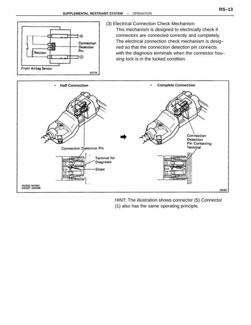
(3) Electrical Connection Check MechanismThis mechanism is designed to electrically check ifconnectors are connected correctly and completely.The electrical connection check mechanism is desig–ned so that the connection detection pin connectswith the diagnosis terminals when the connector hou–sing lock is in the locked condition.
HINT: The illustration shows connector (5) Connector(1) also has the same operating principle.
• Complete Connection• Half Connection
–SUPPLEMENTAL RESTRAINT SYSTEM OPERATIONRS–13

(4) Connector Twin–Lock MechanismWith this mechanism connectors (male and femaleconnectors) are locked by two locking devices toincrease connection reliability. If the primary lock isincomplete, ribs interfere and prevent the secondarylock.
–SUPPLEMENTAL RESTRAINT SYSTEM OPERATIONRS–14

When the vehicle is involved in a frontal collision inthe hatched area (Fig. 1) and the shock is larger thana predetermined level, the SRS is activated automati–cally. Safing sensors are designed to go on at a sma–ller deceleration rate than the front and center airbagsensors. As illustrated in Fig. 2 below, ignition iscaused when current flows to the squib, which hap–pens when a safing sensor and a front airbag sensorand/or the center airbag sensor go on simultaneously.When a deceleration force acts on the sensor, itcauses the squib to ignite. Gas is then generated,increasing the pressure inside the bag rapidly. Theinflated bag breaks open the steering wheel pad andfront passenger airbag assembly. Bag inflation thenends, and the gas is discharged through dischargeholes provided behind the bag. The bag becomesdeflated as a result.
–SUPPLEMENTAL RESTRAINT SYSTEM OPERATIONRS–15

PREPARATIONSST (SPECIAL SERVICE TOOLS
Bolt Length: 35 mm (1.38 in.) Pitch: 1.0 mm (0.039 in.)Diam.: 6.0 mm (0.236 in.)
Tire with disk wheel Width: 185 mm (7028 in.)Inner diem.: 360 mm (14.17 in.)
Tire Width: 185 mm (7.28 in.) Inner diam.: 360mm (14.17 in.)
RECOMMENDED TOOLS
09082–00700 SRS Airbag Deployment Tool
09082–00050 TOYOTA Electrical Tester Set
09213–31021 Crankshaft Pulley Puller
09843–18020 Diagnosis Check Wire
09042–00010 Torx Socket T30
09042–00020 Torx Socket T40 Center airbag sensor assembly
EQUIPMENT
Steering wheel pad
Torque wrench
Airbag disposal
Airbag disposal
Airbag disposal
Airbag disposal
Steering wheel
Vinyl bag
–SUPPLEMENTAL RESTRAINT SYSTEM PREPARATIONRS–16
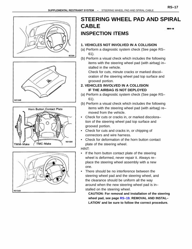
STEERING WHEEL PAD AND SPIRALCABLEINSPECTION ITEMS
1. VEHICLES NOT INVOLVED IN A COLLISION(a) Perform a diagnostic system check (See page RS–
61).(b) Perform a visual check which includes the following
items with the steering wheel pad (with airbag) in–stalled in the vehicle.Check for cuts, minute cracks or marked discol–oration of the steering wheel pad top surface andgrooved portion.
2. VEHICLES INVOLVED IN A COLLISIONIF THE AIRBAG IS NOT DEPLOYED
(a) Perform a diagnostic system check (See page RS–61).
(b) Perform a visual check which includes the followingitems with the steering wheel pad (with airbag) re–moved from the vehicle.
• Check for cuts or cracks in, or marked discolora–tion of the steering wheel pad top surface andgrooved portion.
• Check for cuts and cracks in, or chipping ofconnectors and wire harness.
• Check for deformation of the horn button contactplate of the steering wheel.
HINT:• If the horn button contact plate of the steering
wheel is deformed, never repair it. Always re–place the steering wheel assembly with a newone.
• There should be no interference between thesteering wheel pad and the steering wheel, andthe clearance should be uniform all the wayaround when the new steering wheel pad is in–stalled on the steering wheel.
CAUTION: For removal and installation of the steeringwheel pad, see page RS–19. REMOVAL AND INSTAL–LATION’ and be sure to follow the correct procedure.
–SUPPLEMENTAL RESTRAINT SYSTEM STEERING WHEEL PAD AND SPIRAL CABLERS–17
IF THE AIRBAG IS DEPLOYED(a) Perform a diagnostic system check (See page RS–
61).(b) Perform a visual check which includes the following
items with the steering wheel pad (with airbag) re–moved from he vehicle.
• Check for deformation of the horn button contactplate of the steering wheel.
• Check for damage to the spiral cable connectorand wire harness.
HINT:• If the horn button contact plate of the steering
wheel is deformed, never repair it. Always re–place the steering wheel assembly with a newone.
• There should be no interference between thesteering wheel pad and the steering wheel, andthe clearance should be uniform all the wayaround when the new steering pad is installed onthe steering wheel.
REPLACEMENT REQUIREMENTSIn the following cases, replace the steering wheel pad,steering wheel or spiral cable.CAUTION: For replacement of the steering wheel pad,see page RS– 19.’STEERING WHEEL PAD AND SPIRALCABLE REMOVAL AND INSTALLATION’ and be sure tofollow the correct procedure.• If the airbag has been deployed.• If the steering wheel pad or spiral cable has been
found to be faulty in troubleshooting.• If the steering wheel pad, steering wheel or spiral
cable has been found to be faulty during thecheck in item 1–(b) or 2–(b).
• If the steering wheel pad has been dropped.
–SUPPLEMENTAL RESTRAINT SYSTEM STEERING WHEEL PAD AND SPIRAL CABLERS–18

STEERING WHEEL PAD AND– SPIRALCABLE REMOVAL AND INSTALLATIONNOTICE:• If the wiring connector of the supplemental re–
straint system is disconnected with the ignitionswitch at ON or ACC, diagnostic trouble codes willbe recorded.
• Never use SRS parts from another vehicle. Whenreplacing parts, replace with new parts.
1. DISCONNECT NEGATIVE (–) TERMINAL CABLEFROM BATTERYCAUTION: Work must be started after 90 seconds fromthe time the ignition switch is turned to the ’LOCK’position and the negative (–) terminal cable is discon–nected from the battery (See page RS–2).
COMPONENTS
–SUPPLEMENTAL RESTRAINT SYSTEM STEERING WHEEL PAD AND SPIRAL CABLERS–19
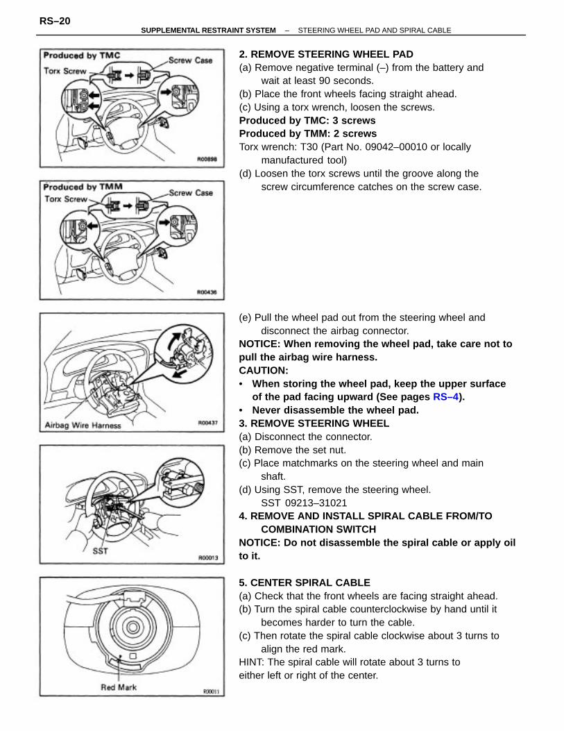
(e) Pull the wheel pad out from the steering wheel anddisconnect the airbag connector.
NOTICE: When removing the wheel pad, take care not topull the airbag wire harness.CAUTION:• When storing the wheel pad, keep the upper surface
of the pad facing upward (See pages RS–4).• Never disassemble the wheel pad.3. REMOVE STEERING WHEEL(a) Disconnect the connector.(b) Remove the set nut.(c) Place matchmarks on the steering wheel and main
shaft.(d) Using SST, remove the steering wheel.
SST 09213–310214. REMOVE AND INSTALL SPIRAL CABLE FROM/TO
COMBINATION SWITCHNOTICE: Do not disassemble the spiral cable or apply oilto it.
2. REMOVE STEERING WHEEL PAD(a) Remove negative terminal (–) from the battery and
wait at least 90 seconds.(b) Place the front wheels facing straight ahead.(c) Using a torx wrench, loosen the screws.Produced by TMC: 3 screwsProduced by TMM: 2 screwsTorx wrench: T30 (Part No. 09042–00010 or locally
manufactured tool)(d) Loosen the torx screws until the groove along the
screw circumference catches on the screw case.
5. CENTER SPIRAL CABLE(a) Check that the front wheels are facing straight ahead.(b) Turn the spiral cable counterclockwise by hand until it
becomes harder to turn the cable.(c) Then rotate the spiral cable clockwise about 3 turns to
align the red mark.HINT: The spiral cable will rotate about 3 turns toeither left or right of the center.
–SUPPLEMENTAL RESTRAINT SYSTEM STEERING WHEEL PAD AND SPIRAL CABLERS–20

7. INSTALL STEERING WHEEL PAD(a) Connect the airbag connector.(b) Install the wheel pad after confirming that the circum–
ference groove of the torx screws is caught on thescrew case.
(c) Using a torx wrench, tighten the screws.Produced by TMC: 3 screwsProduced by TMM: 2 screwsTorque: 8.8 N–m (90 kgf–cm. 78 in.–lbf)
NOTICE:• Make sure the wheel pad is installed to the specified
torque.• If the wheel pad has been dropped, or there are
cracks, dents or other defects in the case or connec–tor, replace the wheel pad with a now one.
• When installing the wheel pad, take care that thewirings do not interfere with other parts and are notpinched between other parts.
8. CHECK STEERING WHEEL CENTER POINT9. CONNECT NEGATIVE (–) TERMINAL CABLE TO
BATTERY
6. INSTALL STEERING WHEEL(a) Align matchmarks on the steering wheel and mainshaft, and install the steering wheel to the main shaft.(b) Install and torque the set nut.
Torque: 35 N–m (360 kgf–cm, 26 ft–Ibf)
(c) Connect the connector.
–SUPPLEMENTAL RESTRAINT SYSTEM STEERING WHEEL PAD AND SPIRAL CABLERS–21

PRECAUTIONS FOR AIRBAG DEPLOYMENT• The airbag produces a sizeable exploding sound
when it deploys, so perform the operation out–of–doors and where it will not create a nuisanceto nearby residents.
• When deploying the airbag, always use the speci–fied SST; SRS AIRBAG DEPLOYMENT TOOL(SST 09082 –00700). Perform the operation in aplace away from electrical noise.
• When deploying an airbag, perform the operationfrom at least 10 m (33 ft) away from the steeringwheel pad.
• The steering wheel pad is very hot when theairbag is deployed, so leave it alone for at least 30minutes after deployment.
• Use gloves and safety glasses when handling asteering wheel pad with deployed airbag.
• Always wash your hands with water after com–pleting the operation.
• Do not apply water, etc. to a steering wheel padwith deployed airbag.
STEERING WHEEL PAD (WITH AIRBAG)DISPOSALWhen scrapping vehicles equipped with a supplemen–tal restraint system or disposing of a steering wheelpad (with airbag), always first deploy the airbag inaccordance with the procedure described below.If any abnormality occurs with the airbag deployment,contact the SERVICE DEPT. of TOYOTA MOTORSALES, U.S.A., INC..Never dispose of a steering wheel pad which has anundeployed airbag.When disposing of a steering wheel pad with anairbag deployed in a collision, follow the same proce–dure given under ”When Scrapping Vehicle, part 5,DISPOSAL OF STEERING WHEEL PAD (WITHAIRBAG)”.
–SUPPLEMENTAL RESTRAINT SYSTEM STEERING WHEEL PAD AND SPIRAL CABLERS–22

3. INSTALL SSTCAUTION: Check that there is no looseness in the steer–ing wheel and steering wheel pad.
(a) Remove the No.1 under cover.(b) Disconnect the airbag connector of the spiral cable.(c) Connect the SST connector to the airbag connector of
the spiral cable.SST 08082–00700
(d) Move the SST to at least 10 m (33 ft) from the front ofthe vehicle.
(e) Close all the doors and windows of the vehicle.NOTICE: Take care not to damage the SST wire harness.
(f) Connect the SST red clip to the battery positive (+)terminal and the black clip to the battery negative (–)terminal.
When scrapping vehicleHINT: Have a battery ready as the power source todeploy the airbag.1. DISCONNECT NEGATIVE (–) TERMINAL CABLE
FROM BATTERYCAUTION: Work must be started after 90 seconds fromthe time the ignition switch is turned to the ’LOCK’position and the negative (–) terminal cable is discon–nected from the battery (See page RS–2).
2. CONFIRM FUNCTIONING OF SST(See page RS–28)SST 09082–00700
–SUPPLEMENTAL RESTRAINT SYSTEM STEERING WHEEL PAD AND SPIRAL CABLERS–23

4. DEPLOY AIRBAG(a) Confirm that no–one is inside the vehicle or within 10
m (33 ft) of the vehicle.(b) Press the SST activation switch and deploy the airbag.HINT: The airbag deploys simultaneously as the LEDof the SST activation switch lights up.5. DISPOSAL OF STEERING WHEEL PAD (WITH
AIRBAG)CAUTION:
• The steering wheel pad is very hot when the airbagis deployed, so leave it alone for at least 30 minutesafter deployment.
• Use gloves and safety glasses when handling a ste–ering wheel pad with deployed airbag.
• Do not apply water, etc. to a steering wheel padwith deployed airbag.
• Always wash your hands with water after complet–ing the operation.
(a) When scrapping a vehicle, deploy the airbag and scrapthe vehicle with the steering wheel pad still installed.
(b) When moving a vehicle for scrapping which has asteering wheel pad with deployed airbag, use glovesand safety glasses.
When disposing of steering wheel pad onlyWhen disposing of the steering wheel pad (with airbag)only, never use the customer’s vehicle to deploy theairbag.Remove the steering wheel pad from the vehicle andbe sure to follow the procedure given below whendeploying the airbag.HINT: Have a battery ready as the power sourcedeploy the airbag.
1. REMOVE STEERING WHEEL PAD (Seepage RS–20)CAUTION:• When removing the steering wheel pad (with
airbag), work must be started after 90 seconds fromthe time the Ignition switch is turned to the LOCKposition and the negative (–) terminal cable is dis–connected from the battery.
• When storing the steering wheel pad, keep theupper surface of the pad facing upward.
–SUPPLEMENTAL RESTRAINT SYSTEM STEERING WHEEL PAD AND SPIRAL CABLERS–24
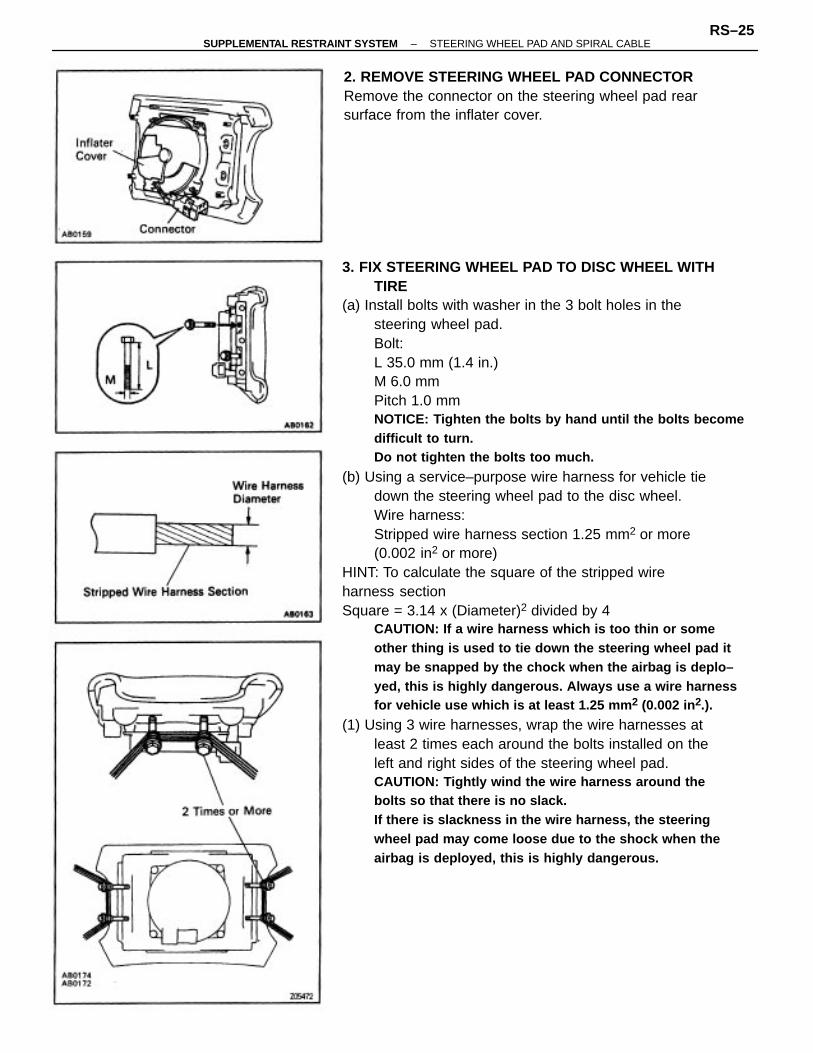
3. FIX STEERING WHEEL PAD TO DISC WHEEL WITHTIRE
(a) Install bolts with washer in the 3 bolt holes in thesteering wheel pad.Bolt:L 35.0 mm (1.4 in.)M 6.0 mmPitch 1.0 mmNOTICE: Tighten the bolts by hand until the bolts becomedifficult to turn.Do not tighten the bolts too much.
(b) Using a service–purpose wire harness for vehicle tiedown the steering wheel pad to the disc wheel.Wire harness:Stripped wire harness section 1.25 mm2 or more(0.002 in2 or more)
HINT: To calculate the square of the stripped wireharness sectionSquare = 3.14 x (Diameter)2 divided by 4
CAUTION: If a wire harness which is too thin or someother thing is used to tie down the steering wheel pad itmay be snapped by the chock when the airbag is deplo–yed, this is highly dangerous. Always use a wire harnessfor vehicle use which is at least 1.25 mm 2 (0.002 in2.).
(1) Using 3 wire harnesses, wrap the wire harnesses atleast 2 times each around the bolts installed on theleft and right sides of the steering wheel pad.CAUTION: Tightly wind the wire harness around thebolts so that there is no slack.If there is slackness in the wire harness, the steeringwheel pad may come loose due to the shock when theairbag is deployed, this is highly dangerous.
2. REMOVE STEERING WHEEL PAD CONNECTORRemove the connector on the steering wheel pad rearsurface from the inflater cover.
–SUPPLEMENTAL RESTRAINT SYSTEM STEERING WHEEL PAD AND SPIRAL CABLERS–25

(2) Face the upper surface of the steering wheel padupward.Separately tie the left and right sides of the steeringwheel pad to the disc wheel through the hub nutholes.Position the steering wheel pad connector so that ithangs downward through a hub hole in the disc wheel.
CAUTION:• Make sure that the wire harness is tight. It is very
dangerous if looseness in the wire harness results inthe steering wheel pad coming free through theshock of the airbag deploying.
• Always tie down the steering wheel pad with thepad side facing upward. It is very dangerous if thesteering wheel pad is tied down with the metal surfacefacing upward as the wire harness will becut by the shock of the airbag deploying and thesteering wheel pad will be thrown into the air.
HINT: The disc wheel will be marked by airbag deploy–ment, so use a redundant disc wheel.4. CONFIRM FUNCTIONING OF SST(See page RS–28)SST 09082–00070
5. INSTALL SSTCAUTION: Place the disc wheel on level ground.(a) Connect the SST connector to the steering wheel pad
connector.SST 09082–00700
NOTICE: To avoid damaging the SST connector and wireharness, do not lock the secondary lock of the twin lock.Also provide some slack for the SST wire harness insidethe disc wheel.
(b) Move the SST to at least 10 m (33 ft) away from thesteering wheel pad tied down on the disc wheel.6. COVER STEERING WHEEL PAD WITH CARDBOARD
BOX OR TIRES(Covering Method Using Cardboard Box)
–SUPPLEMENTAL RESTRAINT SYSTEM STEERING WHEEL PAD AND SPIRAL CABLERS–26

Cover the steering wheel pad with the cardboard boxand weigh the cardboard box down in four places witha at least 196 N (20 kgf. 44 lbf).Size of cardboard box:Must exceed the following dimensionsx= 460 mm (18.11 in.)When dimension y of the cardboard box exceeds thediameter of the disc wheel with tire the steering wheelpad is tied to–x = 460 mm (18.11 in.) + width of tirey = 650 mm (25.59 in.)
NOTICE: It a cardboard box smaller than the size speci–fied is used, the cardboard box will be broken by theshock of the airbag deployment.
(Covering Method Using Tires)Place at least three tires without disc wheel on top ofthe disc wheel with tire to which with tire to which thesteering wheel pad is tied.Tire size: Must exceed the following dimensions–Width 185 mm (7.28 in.)Inner diam 360 mm (14.17 in.)
CAUTION: Do not use tires with disc wheels.NOTICE: The tires by marked by the airbag deployment,so use redundant tires.
7. AIRBAG DEPLOYMENT(a) Connect the SST red clip to the battery positive (+)
terminal and the black clip to the battery negative (–)terminal.
(b) Confirm that no–one is within 10 m (33 ft) of the discwheel the steering wheel pad is tied to.
(c) Press the SST activation switch and deploy the airbag.HINT: The airbag deploys simultaneously as the LEDof the SST activation switch lights up.
–SUPPLEMENTAL RESTRAINT SYSTEM STEERING WHEEL PAD AND SPIRAL CABLERS–27

8. DISPOSAL OF STEERING WHEEL PAD (WITHAIRBAG)CAUTION:
• The steering wheel pad is battery hot when theairbag is deployed, so leave it alone for at least 30minutes after deployment.
• Use gloves and safety glasses when handling a ste–ering wheel pad with deployed airbag.
• Do not apply water, etc. to a steering wheel padwith deployed airbag.
• Always wash your hands with water after complet–ing the operation.
(a) Remove the steering wheel pad from the disc wheel.(b) Place the steering wheel pad in a vinyl bag, tie the end
tightly and dispose of it the same way as other generalparts.
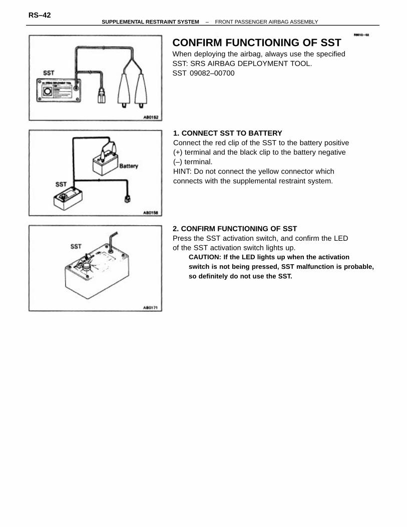
1. CONNECT SST TO BATTERYConnect the red clip of the SST to the battery positive(+) terminal and the black clip to the battery negative(–) terminal.HINT: Do not connect the yellow connector whichconnects with the airbag system.
2. CONFIRM FUNCTIONING OF SSTPress the SST activation switch, and confirm the LEDof the SST activation switch lights up.CAUTION: If the LED lights up when the activationswitch is not being pressed, SST malfunction is probable,so definitely do not use the SST.
CONFIRM FUNCTIONING OF SSTWhen deploying the airbag, always use the specifiedSST: SRS AIRBAG DEPLOYMENT TOOL.SST 09082–00700
–SUPPLEMENTAL RESTRAINT SYSTEM STEERING WHEEL PAD AND SPIRAL CABLERS–28
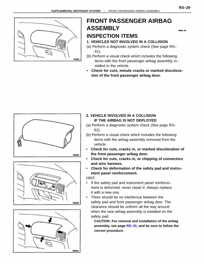
2. VEHICLE INVOLVED IN A COLLISIONIF THE AIRBAG IS NOT DEPLOYED
(a) Perform a diagnostic system check (See page RS–61).
(b) Perform a visual check which includes the followingitems with the airbag assembly removed from thevehicle.
• Check for cuts, cracks in, or marked discoloration ofthe front passenger aribag door.
• Check for cuts, cracks in, or chipping of connectorsand wire harness.
• Check for deformation of the safety pad and instru–ment panel reinforcement.
HINT:• If the safety pad and instrument panel reinforce–
ment is deformed, never repair it. Always replaceit with a new one.
• There should be no interfernce between thesafety pad and front passenger airbag door. Theclearance should be uniform all the way aroundwhen the new airbag assembly is installed on thesafety pad.
CAUTION: For removal and installation of the airbagassembly, see page RS–31, and be sure to follow thecorrect procedure.
FRONT PASSENGER AIRBAGASSEMBLYINSPECTION ITEMS1. VEHICLES NOT INVOLVED IN A COLLISION(a) Perform a diagnostic system check (See page RS–
61).(b) Perform a visual check which includes the following
items with the front passenger airbag assembly in–stalled in the vehicle.
• Check for cuts, minute cracks or marked discolora–tion of the front passenger airbag door.
–SUPPLEMENTAL RESTRAINT SYSTEM FRONT PASSENGER AIRBAG ASSEMBLYRS–29
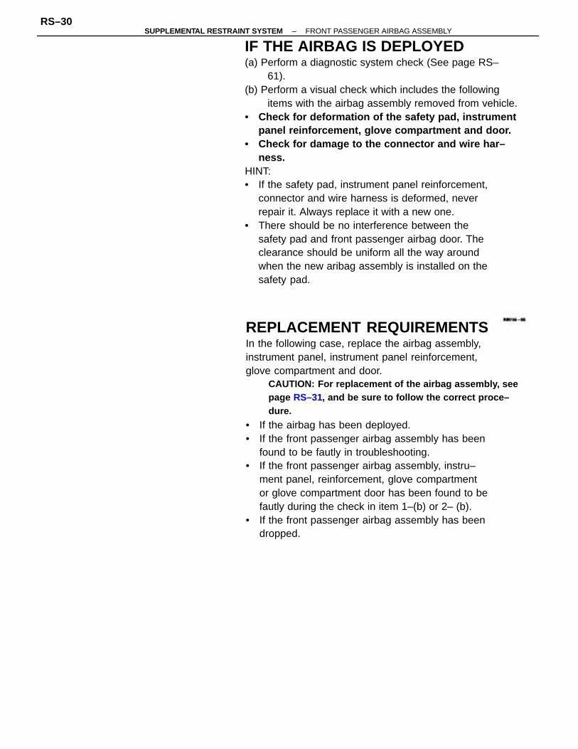
IF THE AIRBAG IS DEPLOYED(a) Perform a diagnostic system check (See page RS–
61).(b) Perform a visual check which includes the following
items with the airbag assembly removed from vehicle.• Check for deformation of the safety pad, instrument
panel reinforcement, glove compartment and door.• Check for damage to the connector and wire har–
ness.HINT:• If the safety pad, instrument panel reinforcement,
connector and wire harness is deformed, neverrepair it. Always replace it with a new one.
• There should be no interference between thesafety pad and front passenger airbag door. Theclearance should be uniform all the way aroundwhen the new aribag assembly is installed on thesafety pad.
REPLACEMENT REQUIREMENTSIn the following case, replace the airbag assembly,instrument panel, instrument panel reinforcement,glove compartment and door.
CAUTION: For replacement of the airbag assembly, seepage RS–31, and be sure to follow the correct proce–dure.
• If the airbag has been deployed.• If the front passenger airbag assembly has been
found to be fautly in troubleshooting.• If the front passenger airbag assembly, instru–
ment panel, reinforcement, glove compartmentor glove compartment door has been found to befautly during the check in item 1–(b) or 2– (b).
• If the front passenger airbag assembly has beendropped.
–SUPPLEMENTAL RESTRAINT SYSTEM FRONT PASSENGER AIRBAG ASSEMBLYRS–30
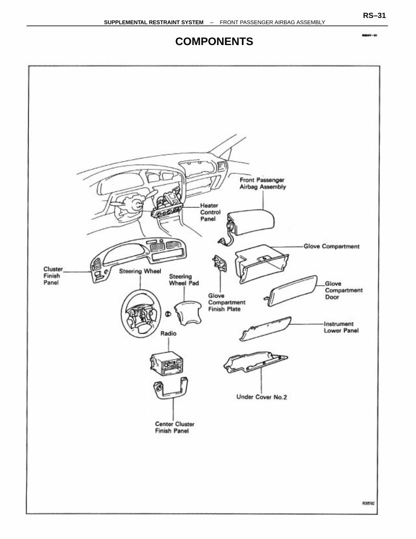
COMPONENTS
–SUPPLEMENTAL RESTRAINT SYSTEM FRONT PASSENGER AIRBAG ASSEMBLYRS–31
FRONT PASSENGER AIRBAG ASSEMBLYREMOVAL AND INSTALLATION
NOTICE: Never use airbag parts from another vehicle.When replacing parts, replace with new parts.
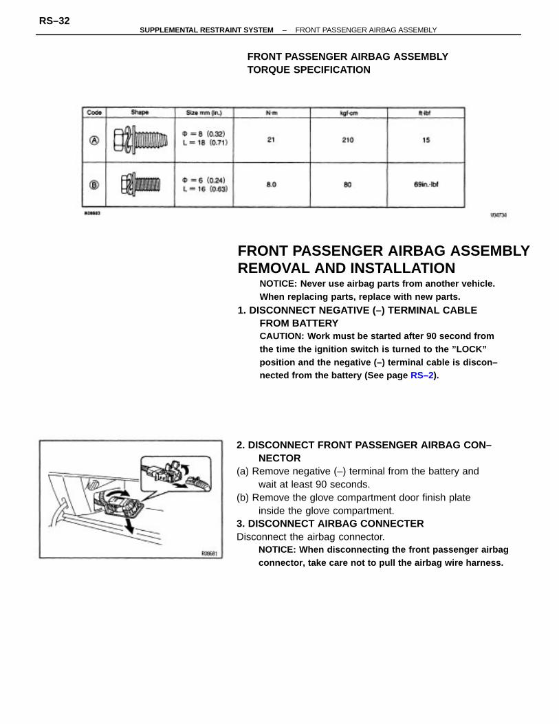
1. DISCONNECT NEGATIVE (–) TERMINAL CABLEFROM BATTERYCAUTION: Work must be started after 90 second fromthe time the ignition switch is turned to the ”LOCK”position and the negative (–) terminal cable is discon–nected from the battery (See page RS–2).
2. DISCONNECT FRONT PASSENGER AIRBAG CON–NECTOR
(a) Remove negative (–) terminal from the battery andwait at least 90 seconds.
(b) Remove the glove compartment door finish plateinside the glove compartment.
3. DISCONNECT AIRBAG CONNECTERDisconnect the airbag connector.
NOTICE: When disconnecting the front passenger airbagconnector, take care not to pull the airbag wire harness.
FRONT PASSENGER AIRBAG ASSEMBLYTORQUE SPECIFICATION
–SUPPLEMENTAL RESTRAINT SYSTEM FRONT PASSENGER AIRBAG ASSEMBLYRS–32

4. REMOVE AND DISCONNECT FOLLOWING PARTS:• Remove steering wheel pad
(See page RS–20)• Remove steering wheel
(See page RS–20)(See page BO –108)• Remove under cover No.2• Remove instrument lower panel• Remove compartment panel• Remove compartment door• Remove combination switch• Remove center cluster finish panel• Remove radio• Remove cluster finish panel• Remove heater control panel
(b) Remove the 5 bolts.(c) Remove the front passenger airbag assembly.CAUTION:• Do not store the front passenger airbag assembly
with the airbag door facing down.• Never disassembly the front passenger airbag
assembly.
6. INSTALL AIRBAG DOOR AND FRONT PASSENGERAIRBAG ASSEMBLY (W/O AIRBAG DOOR)CAUTION: Make sure to replace the new airbag door andthe new airbag assembly (w/o Airbag door) in combina–tion, no alone.
(a) Install the airbag door with the 3 bolts.Torque: 8.0 N–m (80 kgf–cm, 89in.–lbf)
5. REMOVE FRONT PASSENGER AIRBAG(a) Remove the RH side installation bolt.
–SUPPLEMENTAL RESTRAINT SYSTEM FRONT PASSENGER AIRBAG ASSEMBLYRS–33

6. INSTALL FRONT PASSENGER AIRBAG ASSEMBLY(a) Install the front passenger airbag assembly with the 6
bolts.(b) To instrument panel reinforcement.
Diameter = 8 mm (0.32 in.)Torque: 20 N–m (210 kgf–cm, 15 ft–Ibf)
To instrument panelDiameter = 6 mm (0.24 in.)
Torque: 8.0 N–m (80 kgf–cm, 69 in.–Ibf)
NOTICE:• Make sure the front passenger airbag assembly is
installed to the specified torque.• If the front passenger airbag assembly has been
dropped, or there are cracks, dents or other defectsin the case or connector, replace the front passen–ger airbag assembly with a new one.
• When installing the front passenger airbag assem–bly, take care that the wiring do not interfere withother parts and are not pinched between otherparts.
7. INSTALL FOLLOWING PARTS REMOVAL SE–QUENCE IN REVERSE
• Steering wheelTorque: 35 N–m (360 kgf–cm, 26 ft–Ibf)
HINT: When installing the glove compartment, pull theairbag wire harness out from the glove compartmentopening hole.
NOTICE: Do not pull the airbag wire harnesses too stron–gly
8. CONNECT AIRBAG CONNECTOR(a) Connect the airbag connector.(b) Put the connector on the glove compartment door
finish plate.(c) Install the glove compartment door finish plate to the
glove compartment.9. CONNECT NEGATIVE (–) TERMINAL CABLE TO
BATTERY
(b) Using a reveter, install the 2 new rivet.
–SUPPLEMENTAL RESTRAINT SYSTEM FRONT PASSENGER AIRBAG ASSEMBLYRS–34

PRECAUTIONS FOR AIRBAGDEPLOYMENT• The airbag produces a sizeable exploding sound
when it deploys, so perform the operation out–of–doors and where it will not create a nuisanceto nearby residents.
• When deploying the airbag, always use the speci–fied SST: SRS AIRBAG DEPLOYMENT TOOL(SST 09082–00700). Perform the operation in aplace away from electrical noise.
• When deploying an airbag, perform the operationfrom at least 10 m (33 ft) away from the frontpassenger airbag assembly.
• The front passenger airbag assembly is very hotwhen the airbag is deployed, so leave it alone forat least 30 minutes after deployment.
• Use gloves and safety glasses when handling afront passenger airbag assembly with deployedairbag.
• Always wash your hands with water after com–pleting the operation.
• Do not apply water, etc., to a front passengerairbag assembly deployed airbag.
FRONT PASSENGER AIRBAG ASSEMBLYDISPOSALWhen scrapping vehicles equipped with an supple–mental restraint system or disposing of a front pas–senger airbag assembly, always first deploy the airbagin accordance with the procedure described below.If any abnormality occurs with the airbag deployment,contact the SERVICE DEPT. of TOYOTA MOTORSALES, U.S.A., INC..Never dispose of a front passenger airbag assemblywhich has an undeployed airbag.When disposing of a front passenger airbag assemblywith an airbag deployed in a collision, follow the sameprocedure given under ”WHEN SCRAPPING THE VE–HICLE, part 5, DISPOSAL OF FRONT PASSENGERAIRBAG ASSEMBLY”.
–SUPPLEMENTAL RESTRAINT SYSTEM FRONT PASSENGER AIRBAG ASSEMBLYRS–35

When scrapping vehicleHINT: Have a battery ready as the power source todeploy the airbag.1. DISCONNECT NEGATIVE (–) TERMINAL CABLE
FROM THE BATTERYCAUTION: Work must be started after 90 seconds fromthe time the ignition switch is turned to the ’LOCK’position and the negative (–) terminal cable is discon–nected from the battery (See page RS–2).
2. CONFIRM FUNCTIONING OF SST(See page RS–42)SST 09082–00700
3. DISCONNECT CONNECTORCAUTION: Check that there is no looseness in the frontpassenger airbag assembly.
(a) Remove the glove compartment door finish plateinside the glove compartment.
(b) Disconnect the center airbag sensor assembly con–nector from the wiring harness connector.
4. INSTALL SST(a) Connect the SST connector to the airbag connector
and lock the secondary lock of the twin lock.SST 09082–00700
–SUPPLEMENTAL RESTRAINT SYSTEM FRONT PASSENGER AIRBAG ASSEMBLYRS–36

6. DEPLOY AIRBAG(a) Confirm that no–one is inside the vehicle or within 10
m (33 ft) of the vehicle.(b) Press the SST activation switch and deploy the airbag.HINT: The airbag deploys simultaneously as the LEDof the SST activation switch lights up.6. DISPOSAL OF FRONT PASSENGER AIRBAG AS–
SEMBLYNOTICE:• The front passenger airbag assembly is very out not
when the airbag is deployed, so leave it alone for atleast 30 minutes after deployment.
• Use gloves and safety glasses when handling a frontpassenger airbag assembly with deployed airbag.
• Do not apply water, etc., to a front passenger airbagasssembly with deployed airbag.
• Always wash your hands with water after complet–ing the operation.
When scrapping a vehicle, deploy the airbag and scrapthe vehicle with the front passenger airbag assemblystill installed.
(b) Move the SST to at least 10 m (33 ft) from the front ofthe vehicle.
(c) close all the doors and windows of the vehicle.NOTICE: Take care not change the SST wire harness.
(d) Connect the SST red clip to the battery positive (+)terminal and the black clip to the battery negative (–)terminal.
–SUPPLEMENTAL RESTRAINT SYSTEM FRONT PASSENGER AIRBAG ASSEMBLYRS–37

When disposing of front passenger airbagassembly onlyWhen disposing of the front passenger airbag assem–bly (w/ airbag) only, never use the customer’s vehicleto deploy the airbag.Remove the front passenger airbag assembly from thevehicle and be sure to follow the procedure givenbelow when diploying the airbag.HINT: Have a battery ready as the power source todeploy the airbag.
2. FIX FRONT PASSENGER AIRBAG ASSEMBLY TOTIRE
(a) Install bolts with washers in the 2 bolt holes in thefront passenger airbag assembly.Bolt:L 35.0 mm (1.4 in.)M 6.0 m mPitch 1.0 mmNOTICE: Tighten the bolts by hand until the bolts becomedifficult to turn.Do not tighten the bolts too much.
1. REMOVE FRONT PASSENGER AIRBAG ASSEMBLYCAUTION:
• When removing the front passenger airbag assem–bly, work must be started after 90 seconds from thetime the ignition switch is turned to the ”LOCK”position and the negative (–) terminal cable is dis–connected from the battery (See page RS–2).
• Store the front passenger airbag assembly with theairbag door facing up.
–SUPPLEMENTAL RESTRAINT SYSTEM FRONT PASSENGER AIRBAG ASSEMBLYRS–38

(2) Position the front passenger airbag assembly insidethe tire with the airbag door facing inside.Tie the wire harness to the tire.Tire size: Must exceed the following dimensionsWidth 185 mm (7.28 in.)Inner diameter 360 mm (14.17 in.)
CAUTION:• Make sure the wire harness is tight. It is very dan–
gerous if a loose wire harness results in the frontpassenger airbag assembly coming free due to theshock of the airbag deploying.
• Always tie down the front passenger airbag assem–bly with the airbag door facing inside.
NOTICE: The tire will be marked by the airbag deploy–ment, so use a redundant tire.
CAUTION: If a wire harness which is too thin or someother thing is used to tie down the front passenger airbagassembly, it may be snapped by the shock when theairbag is deployed, this is highly dangerous.Always use a wire harness for vehicle use which is atleast 1.25 mm 2 (0.002 in 2).
(1) Using 3 wire harness, wrap the wire harnesses at least2 times each around the bolts installed on the left andright side of the front passenger airbag assembly.CAUTION: Tightly wind the wire harness around thebolts so that there is o slack. lf there is slackness in thewire harness, the front passenger airbag assembly maycome loose due to the shock when the airbag is deployed,this is highly dangerous.
(b) Using a service–purpose wire harness for vehicle, tiedown the front passenger airbag assembly to the tire.Wire harness–. Stripped wire harness section 1.25 mm2
or more (0.002 in2 or more).HINT: To calculate the square of the stripped wireharness section –Square = 3.14 x (Diarneter)2 divided by 4
–SUPPLEMENTAL RESTRAINT SYSTEM FRONT PASSENGER AIRBAG ASSEMBLYRS–39

HINT: Place the SST connect and wire harness insidetires. Provide at least a meter 1 m (3 ft) of slack for thewire harness.5. INSTALL SST(a) Connect the front passenger airbag assembly connec–
tor and lock the secondary lock of the twin lock.(b) Connect the SST connector and lock the secondary
lock of the twin lock.SST 09082–00700
6. AIRBAG DEPLOYMENT(a) Connect the SST red clip to the battery positive (+)
terminal and the black clip to the battery negative (–)terminal.
(b) Confirm that no–one is within 10 m (33 ft) of the tirethe front passenger airbag assembly is tied to.
(c) Press the SST activation switch and deploy the airbag.HINT: The airbag deploys simultaneously as the LEDof the SST activation switch lights up.
4. PLACE TIRES(a) Place at least 2 tires under the tire to which the front
passenger airbag assembly is tied.(b) Place at least 2 tires over the tire to which the front
passenger airbag assembly is tied. The top tire shouldhave the wheel installed.
(c) Tie the tires together by 2 wire harnesses.CAUTION: Make sure that the wire harnesses are tight. Itis very dangerous if loose wire harnesses result in thetires coming free due to the shock of the airbag deploy–ing.
3. CONFIRM FUNCTIONING OF SST(See page RS–42)SST 09082–00700
–SUPPLEMENTAL RESTRAINT SYSTEM FRONT PASSENGER AIRBAG ASSEMBLYRS–40

7. DISPOSAL OF FRONT PASSENGER AIRBAG AS–SEMBLYCAUTION:
• The front passenger airbag assembly is very hotwhen the airbag is deployed, so leave it alone for atleast 30 minutes after deployment.
• Use gloves and safety glasses when handling a frontpassenger airbag asssembly with deployed airbag.
• Do not apply water, etc., to a front passenger airbag as-sembly with deployed airbag.
• Always wash your hand with water after completingthe operation.
(a) Remove the front passenger airbag assembly from thetire.
(b) Place the front passenger airbag assembly in a vinylbag, tie the end tightly and dispose of it the same wayas other general parts.
–SUPPLEMENTAL RESTRAINT SYSTEM FRONT PASSENGER AIRBAG ASSEMBLYRS–41
1. CONNECT SST TO BATTERYConnect the red clip of the SST to the battery positive(+) terminal and the black clip to the battery negative(–) terminal.HINT: Do not connect the yellow connector whichconnects with the supplemental restraint system.
2. CONFIRM FUNCTIONING OF SSTPress the SST activation switch, and confirm the LEDof the SST activation switch lights up.
CAUTION: If the LED lights up when the activationswitch is not being pressed, SST malfunction is probable,so definitely do not use the SST.
CONFIRM FUNCTIONING OF SSTWhen deploying the airbag, always use the specifiedSST: SRS AIRBAG DEPLOYMENT TOOL.SST 09082–00700
–SUPPLEMENTAL RESTRAINT SYSTEM FRONT PASSENGER AIRBAG ASSEMBLYRS–42
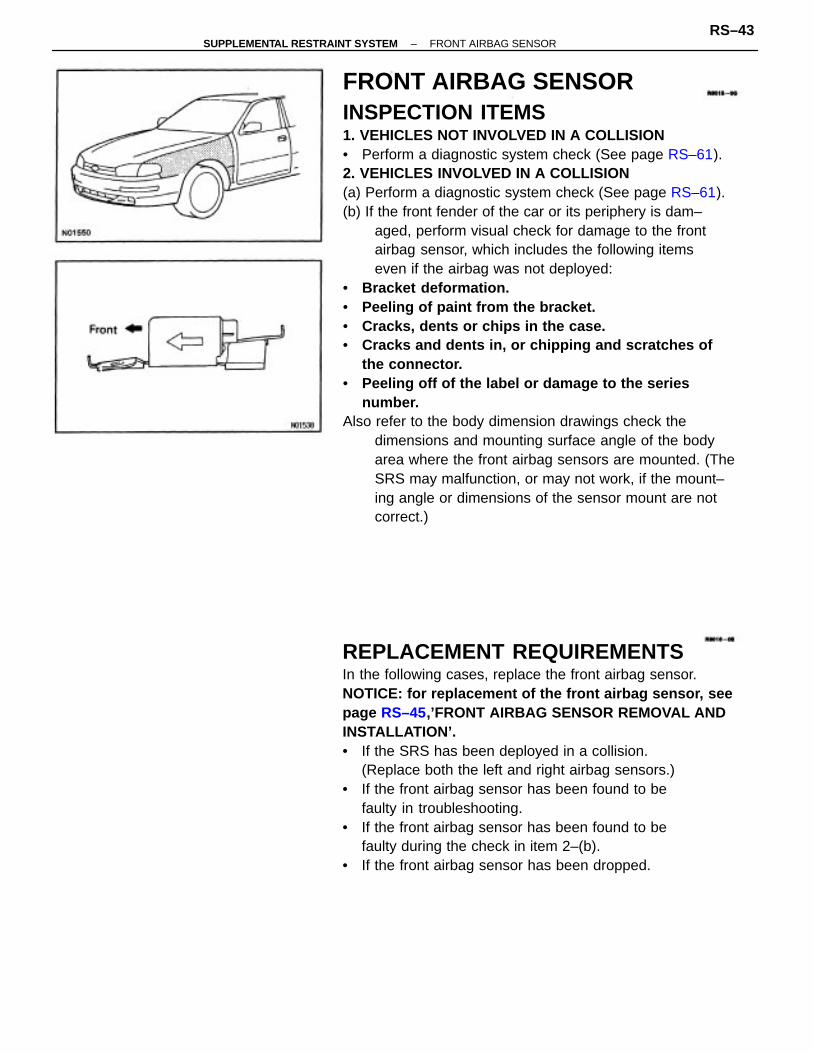
FRONT AIRBAG SENSORINSPECTION ITEMS1. VEHICLES NOT INVOLVED IN A COLLISION• Perform a diagnostic system check (See page RS–61).2. VEHICLES INVOLVED IN A COLLISION(a) Perform a diagnostic system check (See page RS–61).(b) If the front fender of the car or its periphery is dam–
aged, perform visual check for damage to the frontairbag sensor, which includes the following itemseven if the airbag was not deployed:
• Bracket deformation.• Peeling of paint from the bracket.• Cracks, dents or chips in the case.• Cracks and dents in, or chipping and scratches of
the connector.• Peeling off of the label or damage to the series
number.Also refer to the body dimension drawings check the
dimensions and mounting surface angle of the bodyarea where the front airbag sensors are mounted. (TheSRS may malfunction, or may not work, if the mount–ing angle or dimensions of the sensor mount are notcorrect.)
REPLACEMENT REQUIREMENTSIn the following cases, replace the front airbag sensor.NOTICE: for replacement of the front airbag sensor, seepage RS–45,’FRONT AIRBAG SENSOR REMOVAL ANDINSTALLATION’.• If the SRS has been deployed in a collision.
(Replace both the left and right airbag sensors.)• If the front airbag sensor has been found to be
faulty in troubleshooting.• If the front airbag sensor has been found to be
faulty during the check in item 2–(b).• If the front airbag sensor has been dropped.
–SUPPLEMENTAL RESTRAINT SYSTEM FRONT AIRBAG SENSORRS–43

FRONT AIRBAG SENSOR REMOVAL ANDINSTALLATIONNOTICE:• If the wiring connector of the supplemental re–
straint system is disconnected with the ignitionswitch at ON or ACC, diagnostic trouble codes willbe recorded.
• Never use SRS parts from another vehicle. Whenreplacing parts, replace with now parts.
• Never reuse the sensor involved in a collision whenthe SRS has deployed.
• Never repair a sensor in order to reuse it.1. DISCONNECT NEGATIVE (–) TERMINAL CABLE
FROM BATTERYCAUTION: Work must be started after 90 seconds fromthe time the ignition switch is turned to the ’LOCK’position and the negative (–) terminal cable Is discon–nected from the battery (See page RS–2).
COMPONENTS
–SUPPLEMENTAL RESTRAINT SYSTEM FRONT AIRBAG SENSORRS–44

2. REMOVE FENDER LINER3. REMOVE FRONT AIRBAG SENSOR(a) Disconnect the connector.(b) Remove the bolt and sensor.4. INSTALL FRONT AIRBAG SENSORInstall the sensor with the arrow on the sensor facingtoward the front of the vehicle.
Torque: 25 N–m (260 kgf–cm, 19 ft–lbf)
NOTICE:• Make sure the sensor is installed to the specified
torque.• If the sensor has been dropped, or there are cracks
dents or other defects in the case, bracket or con–nector, replace the sensor with a new one.
• The sensor set bolts have been anti–rust treatedWhen the sensor is removed, always replace the setbolts with new ones.
• After installation, shake the sensor to check thatthere is no looseness.
• The front sensor is equipped with an electrical con–nection check mechanism. Be sure to lock this mech–anism securely when connecting the connector. Ifthe connector is not securely locked, a malfunctioncode will be detected by the diagnosis system.
• Check that the dimensions of the body where thefront airbag sensor is installed match those in thebody dimension drawings in the BODY section.(The SRS may malfunction, or may not work, if themounting angle or dimensions of the sensor mountare not correct.)
5. INSTALL FENDER LINER6. CONNECT NEGATIVE (–) TERMINAL CABLE TO
BATTERY
–SUPPLEMENTAL RESTRAINT SYSTEM FRONT AIRBAG SENSORRS–45

CENTER AIRBAG SENSORASSEMBLYINSPECTION ITEMS1. VEHICLES NOT INVOLVED IN A COLLISION• Perform a diagnostic system check (See page RS–61).2. VEHICLES INVOLVED IN A COLLISION
IF THE SRS IS NOT DEPLOYED• Perform a diagnostic system check (See page RS–61).
IF THE SRS IS DEPLOYED• Replace the center airbag sensor assembly certain–
ly.
REPLACEMENT REQUIREMENTS
In the following cases, replace the center airbagsensor assembly.NOTICE: For replacement of the center airbag sensorassembly, see page RS–47, ’CENTER AIRBAG SENSORASSEMBLY REMOVAL AND INSTALLATION”.• If the SRS has been deployed in a collision.• If the center airbag sensor assembly has been
found to be faulty in troubleshooting.• If the center airbag sensor assembly has been
dropped.
–SUPPLEMENTAL RESTRAINT SYSTEM CENTER AIRBAG SENSOR ASSEMBLYRS–46

CENTER AIRBAG SENSOR ASSEMBLYREMOVAL AND INSTALLATIONNOTICE:• Do not open the cover or the case of the ECU and
various computers unless absolutely necessary. (Ifthe IC terminals are touched, the IC may be destr–oyed by static electricity.)
• Never use SRS parts from another vehicle. Whenreplacing parts, replace with new parts.
• Never reuse the center airbag sensor assembly in–volved in a collision when the airbag has deployed.
• Never repair a sensor in order to reuse it.1. DISCONNECT NEGATIVE (–) TERMINAL CABLE
FROM BATTERYCAUTION: Work must be started after 90 seconds fromthe time the ignition switch is turned to the ’LOCK’position and the negative (–) terminal cable is discon–nected from the battery (See page RS–2).
COMPONENTS
–SUPPLEMENTAL RESTRAINT SYSTEM CENTER AIRBAG SENSOR ASSEMBLYRS–47

(b) Disconnect and connect connector.NOTICE: Removal and installation of the connector isdone with the sensor assembly installed.
(c) Using a torx wrench, tighten the 3 screws.Torx wrench: T40 (Part No. 09042–00020 or locallymanufactured tool)Torque: 20 N–m (200 kgf–cm, 14 ft–lbf)
NOTICE:• Make sure the sensor assembly is installed to the
specified torque.• If the sensor assembly has been dropped, or there
are cracks, dents or other defects in the case, brack–et or connector, replace the sensor assembly with anew one.
• When installing the sensor assembly, take care thatthe airbag wiring does not interfere with other partsand is not pinched between other parts.
• After installation, shake the sensor assembly tocheck that there is no looseness.
3. CONNECT NEGATIVE (–) TERMINAL CABLE TOBATTERY
2. REMOVE AND INSTALL CENTER AIRBAG SENSORASSEMBLY
(a) Using a torx wrench, loosen and tighten the 3 screws.Torx wrench: T40 (Part No. 09042–00020 or locallymanufactured tool)
–SUPPLEMENTAL RESTRAINT SYSTEM CENTER AIRBAG SENSOR ASSEMBLYRS–48
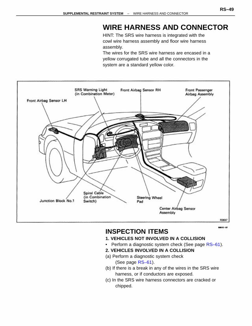
INSPECTION ITEMS1. VEHICLES NOT INVOLVED IN A COLLISION• Perform a diagnostic system check (See page RS–61).2. VEHICLES INVOLVED IN A COLLISION(a) Perform a diagnostic system check
(See page RS–61).(b) If there is a break in any of the wires in the SRS wire
harness, or if conductors are exposed.(c) In the SRS wire harness connectors are cracked or
chipped.
WIRE HARNESS AND CONNECTORHINT: The SRS wire harness is integrated with thecowl wire harness assembly and floor wire harnessassembly.The wires for the SRS wire harness are encased in ayellow corrugated tube and all the connectors in thesystem are a standard yellow color.
–SUPPLEMENTAL RESTRAINT SYSTEM WIRE HARNESS AND CONNECTORRS–49

REPLACEMENT REQUIREMENTSIn the following cases, replace the wire harness orconnector.• If any part of the SRS wire harness or any con–
nector has been found to be faulty in troublesh–ooting.
• If any pant of the SRS wire harness or any con–nector has been found to be faulty during thecheck in item 2–(b) or (c).
NOTICE: If the wire harness used in the SRS is damaged,replace the whole wire harness assembly.When the connector to the front airbag sensors can berepaired alone (when there is no damaged to the wireharness), use the repair wire specially designed for thepurpose (See page RS–13).
REPAIR WIRE FOR FRONT AIRBAGSENSOR REPLACEMENTRepair wire with 2 pressure–contact sleeves (PartNo. 82988–24010) has been prepared for exclusiveuse in repairing connector damage etc. caused byfrontal collision of the vehicle.When repairing the front airbag sensor connector onthe wire harness side, always use the special repairwire.
NOTICE: Do not replace the connector housing or termi–nal only.
AIRBAG REPAIRWIRE REPLACEMENTCAUTION: Work must be started after 90 seconds fromthe time the ignition switch is turned to the ’LOCK’position and the negative (–) terminal cable is discon–nected from the battery (See page RS–2).
1. DISCONNECT WIRE HARNESS AT VEHICLE SIDE(a) Remove the cover at the rear of the connect housing
and expose the wire harness.(b) Cut the wire harness behind the connector housing.HINT: The operation is performed more easily if thewire harness is left as long as possible.
–SUPPLEMENTAL RESTRAINT SYSTEM WIRE HARNESS AND CONNECTORRS–50

2. CONNECT FRONT AIRBAG SENSOR WIRE HAR–NESS AT VEHICLE SIDE AND REPAIR WIRE
(a) Start stripping at least 8 mm (0.31 in.) to 11 mm (0.43in.) away from the end of the existing harness atvehicle side and also from the end of the repair wire.NOTICE: Take care not to damage the wire when stripp–ing the wire harness lead. After finishing the operation,visually inspect the wire. If there Is any damaged. per–form the operation again.
(b) Overlap the 2 stripped wire ends inside of the pres–sure–contact sleeve as illustrated in the left.
HINT: The blue pressure–contact sleeve (Part No.82999–12020) is available individually.
(c) The crimping tool (AMP Part No. 69060) has colormarks on it. Place the sleeve in the correct section ofthe tool according to the color of the sleeve itself.
HINT: You might find it easier if you use a miniaturescrewdriver as a guide as you insert wires into thesleeve.
–SUPPLEMENTAL RESTRAINT SYSTEM WIRE HARNESS AND CONNECTORRS–51

3. PROTECT JOINED SECTIONWrap silicon tape around the joins to protect themfrom water.HINT:• Before starting the operation, thoroughly wipe
dirt and grease off the sections to be joined.• If the adhesive surfaces of two tapes come in
contact they will stick together and will not comeapart, so do not remove the backing film exceptwhen using the tape.
• Do not let oil and dust, etc., get on the tapesurface.
(a) Ready about 100 mm (3.94 in.) of silicon tape (PartNo. 08231–00045) and peel oft the film.
(b) Stretch the silicon tape until its width is reduced byhalf.
(c) About 10 mm (0.39 in.) from the end of the pressurecontact sleeve, wrap the silicon tape around thesleeve 3 or more times while stretching the tape.
(d) with the center of the sleeve correctly placed be–tween the crimping jaws, squeeze the crimping tooluntil either end comes into contact at the sectionmarked by ”CLOSE HERE”.
HINT: Check to see that the sleeve and wires are stillin the correct position before closing the crimping toolends with steady pressure.
(e) Pull the joined wires to either end. Make sure that theyare joined firmly by the sleeve.NOTICE: If the joined wire come loose the splice is defec–tive, so replace the sleeve and repeat the procedure.
(f) Crimp both ends of the sleeve with the crimping toolat the ”INS” position.
–SUPPLEMENTAL RESTRAINT SYSTEM WIRE HARNESS AND CONNECTORRS–52

(d) Wrap the remaining part of sleeve with half of thetape overlapping at each turn.
(e) Firmly wrap the tap 2 times or more about 10 mm(0.39 in.) from the other end of the pressure contact
sleeve, then wrap the tap back towards the start againand firmly finish winding the tape around the center ofthe sleeve.
(g) After applying the silicon tape, apply vinyl tape on thecorrugated tube of repair wire side over to the cor–rugated tube of vehicle wire harness side.
(f) Fix the corrugated tube to the wire using silicon tape.
–SUPPLEMENTAL RESTRAINT SYSTEM WIRE HARNESS AND CONNECTORRS–53

– MEMO
–
–SUPPLEMENTAL RESTRAINT SYSTEM WIRE HARNESS AND CONNECTORRS–54

TROUBLESHOOTING
–SUPPLEMENTAL RESTRAINT SYSTEM TROUBLESHOOTINGRS–55

HOW TO PROCEED WITH TROUBLESHOOTINGMalfunction symptoms of the supplemental restraint system are difficult to confirm, so the diagnostic trou–ble codes become the most important source of information when troubleshooting. Perform troubleshootingof the supplemental restraint system in accordance with the following procedure:HINT: Do not disconnect the battery negative (–) terminal cable until step [3] , Diagnostic Trouble CodeCheck and Recording, has been completed.[1] CUSTOMER PROBLEM ANALYSISUsing the CUSTOMER PROBLEM ANALYSIS CHECK SHEET (See page RS–60) for reference, ask thecustomer in as much detail as possible about the problem.
[2] WARNING LIGHT CHECKCheck the SRS warning light. If the light remains on, a malfunction is stored in the center airbag sensor,assembly, so proceed to step [3] . If the SRS warning light is not on, a malfunction has occurred in theSRS warning light circuit, so perform troubleshooting for SRS Warning Light System Malfunction.HINT: Code 22 is recorded when a malfunction occurs in the SRS warning light system.If an open malfunction occurs in the SRS warning light system, the SRS warning light does not light up,so that until the malfunction is repaired, the diagnostic trouble codes cannot be confirmed.
[3] DIAGNOSTIC TROUBLE CODE CHECK AND RECORDINGCheck the diagnostic trouble codes and make a note of any malfunction codes which are output. If anormal code is output, an abnormality in the power source circuit may have occurred, so performtroubleshooting for source voltage in step [8] .If code 22 is output, skip steps [4] and [5] and proceed to step [7] .
[4] MALFUNCTION CODE CLEARANCEClear the malfunction code.HINT: The malfunction code output in step [3] indicates that a malfunction has occurred in the circuitdesignated by the malfunction code, but does not indicate whether the malfunction is still occurring orwhether it was in the past. ,Accordingly, it is necessary to find out the present condition of the malfunction occurrence by clearingthe malfunction code and performing the diagnostic trouble code check again. If this operation isneglected and troubleshooting is performed using only the malfunction code confirmed in step [3] ,isolating the problem component becomes difficult and invites mistaken diagnosis.
[5] DIAGNOSTIC TROUBLE CODE CHECK AND RECORDINGAfter repeating ignition switch ON–OFF operation (ON: wait 20 secs., OFF: wait 20 secs.) 5 times, checkthe diagnostic trouble code. If any code is output, the malfunction is still occurring, so proceed to step[7].Bearing in mind that a malfunction code was registered in step [3] , provided that the normal code ispresently output, use the methods described in step [6] to simulate the malfunction.NOTICE: When connecting the battery after clearing the malfunction code, always do it with theignition switch in ”LOCK” position. When the battery has been reconnected, turn the ignition switchto ACC or ON position after at least 2 seconds have elapsed.If the battery is reconnected with the ignition switch in ACC or ON position, or the ignition switch isturned to ACC or ON within 2 seconds of connecting the battery, it is possible that the diagnosissystem will not operate normally.
–SUPPLEMENTAL RESTRAINT SYSTEM TROUBLESHOOTINGRS–56

[6] SYMPTOM SIMULATION
[7] DIAGNOSTIC TROUBLE CODE CHARTProceed to the appropriate flow chart in step [8] in accordance with the malfunction code found instep [5] or [6] .[8] CIRCUIT INSPECTION [9] REPAIRFind out if the problem lies in a sensor, actuator or wire harness and connector, and repair the prob-lem.After the problem part is repaired, reinstall the disassembled parts. Do not start work until 90 secondsafter the ignition switch is turned to the LOCK position and the negative (–) terminal cable is dis–connected.CAUTION: If incorrect procedure is used, a malfunction may occur in the system or there isthe danger that airbag may be accidentally deploy during the repair operation. Carefully readthe GENERAL DESCRIPTION (See page RS–2) and the cautions for each operation, performrepairs in the correct order using the correct methods.HINT: The following illustration for the CIRCUIT INSPECTION shows each connector for the SRSsquib circuit.
–SUPPLEMENTAL RESTRAINT SYSTEM TROUBLESHOOTINGRS–57

[10] MALFUNCTION CODE CLEARANCEWhen all the malfunction codes found in steps [5] and [6] have been repaired, clear the malfunctioncodes.[11] DIAGNOSTIC TROUBLE CODE CHECKAfter repeating ignition switch ON–OFF operation (ON: wait 20 secs., OFF: wait 20 secs.) 5 times,checkthe diagnostic trouble codes. If a code is displayed, return to step [7] and troubleshoot the displayedmalfunction code.
NOTICE: When connecting the battery after clearing the malfunction code, always do it with theignition switch in ”LOCK” position. When the battery has been reconnected, turn the ignition switchto ACC or ON position after at least 20 seconds have elapsed.If the battery is reconnected with the ignition switch in ACC or ON position, or the ignition switch isturned to ACC or ON within 20 seconds of connecting the battery, it is possible that the diagnosissystem will not operate normally.
[12] CONFIRMATION TESTCheck the warning light again and confirm that all the malfunctions have been repaired. If the warninglight indicates and abnormally, repeat the operation again from step [2] .
–SUPPLEMENTAL RESTRAINT SYSTEM TROUBLESHOOTINGRS–58

: Diagnostic steps permitting the use of the TOYOTA hand–held tester.
Vehicle Brought to Workshop
Customer Problem Analysis
Warning Lignt Check
Remains ON
Does Not Light Up
Diagnostic Trouble Code Check and Recording
RS–60
RS–61
RS–61
Normal Code
Malfunction Code
Malfunction Code Clearance
RS–65
Diagnostic Trouble Code Check and Recording
RS–61
Normal Code
Malfunction Code
Diagnostic Trouble Code Matrix Chart
RS–69
Malfunction Code
Normal Code
Circuit Inspection
Identification of problems
RS–76
Repair
Malfunction Code Clearance
RS–67
RS–65
RS–61
Malfunction Code
Confirmation Test
END
Diagnostic Trouble Code Check
Symptom Simulation
–SUPPLEMENTAL RESTRAINT SYSTEM TROUBLESHOOTINGRS–59

CUSTOMER PROBLEM ANALY SIS CHECK SHEET
–SUPPLEMENTAL RESTRAINT SYSTEM TROUBLESHOOTINGRS–60

DIAGNOSIS INSPECTIONSRS warning light check(a) Turn the ignition switch to ACC or ON and check that the
SRS warning light lights up.(b) Check that the SRS warning light goes out after approx. 6
seconds.HINT:• When the ignition switch is at ACC or ON and the SRS
warning light remains on, the center airbag sensor as–seemly has detected a malfunction code.
• If, after approx. 6 seconds have elapsed, the SRS warn–ing light sometimes lights up or the SRS warning lightlights up even when the ignition switch is OFF, a shortin the SRS warning light circuit can be considered like–ly. Proceed to SRS warning light system (always lit up,when ignition switch LOCK position) on page RS–146.
Diagnostic trouble code checkUsing diagnosis check wire:1. OUTPUT DIAGNOSTIC TROUBLE CODE(a) Turn the ignition switch to ACC or ON position and waitApprox. 20 seconds.(b) Using SST, connect terminals Te and El of the DLC1 or
DLC2.SST 09843 – 18020NOTICE: Never make a mistake with the terminal connec–tion position as this will cause a malfunction.
–SUPPLEMENTAL RESTRAINT SYSTEM TROUBLESHOOTINGRS–61

2. READ DIAGNOSTIC TROUBLE CODERead the 2–digit diagnostic trouble code as indicated by thenumber of times the SRS warning light blinks. As anexample, the blinking patterns, normal, 11 and 31 are asshown on the illustration.• Normal code indication
The light will blink 2 times per second.• Malfunction code indication
In the event of a malfunction, the light will blink. Thenumber represented by the first blink code outputindicates the first digit of a 2–digit diagnostic troublecode. After a 1.5 second pause, the second blink codewill indicate the second digit.If there are 2 or more codes, there will be a 2.5 secondpause between each. After all the codes have beenoutput, there will be a 4.0 second pause and they will allbe repeated.
HINT:• In the event of a number of trouble codes, indication will
1st from the smallest numbered code to the larger.• If it does not output a diagnostic trouble code or outputs
a diagnostic trouble code without terminal connection,proceed to the Tc terminal circuit inspection on page RS–127.
Using TOYOTA hand–held Tester(a) Hook up the TOYOTA hand–held tester to the DLC1 or
DLC2.(b) Read the diagnostic trouble codes by following the prompts
on the tester screen.HINT: Please refer to the TOYOTA hand–held testeroperator ’s manual for further details.
–SUPPLEMENTAL RESTRAINT SYSTEM TROUBLESHOOTINGRS–62

• Steering wheel pad (squib)• Front passenger airbag sensor
(squib)• Front airbag sensor• Spiral cable• Center airbag sensor assembly• Wire harness
• Steering wheel pad (squib)• Front passenger airbag sensor
(squib)• Front airbag sensor• Spiral cable• Center airbag sensor assembly• Wire harness
• Short in squib circuit orfront airbag sensorcircuit (to ground)
• Front airbag sensor ormalfunction
• Center airbag sensorassembly malfunction
• Front passenger airbag assembly• Wiring harness• Center airbag sensor assembly• Wire harness
• Front passenger airbag assembly• Wiring harness• Center airbag sensor assembly• Wire harness
• Steering wheel pad (squib)• Spiral cable• Center airbag sensor assembly• wire harness
• Steering wheel pad (squib)• Spiral cable
Center airbag sensor assembly• Wire harness
• Short in passengerairbag squib circuit(between P+ wireharness and P+ wireharness)
• Front airbag sensor• Center airbag sensor assembly• Wire harness
• SRS warning light• Center airbag sensor assembly• Wire harness
• Short in squib circuit(between D+ wireharness and D– wireharness)
• Short in squib circuit(to +B)
• Open in front airbagcircuit
• Open in center airbagsensor assemblyconnector malfunction
• Battery• Center airbag sensor assembly
• Center airbag sensor assembly• Wire harness
DIAGNOSTIC TROUBLE CODES
• Center airbag sensorassembly malfunction
• SRS warning lightsystem malfunction
• Open in front airbagsensor circuit
• Open in passengerairbag squib circuit
• Open in driver sideairbag squib circuit
• Center airbag sensor assembly
• Source voltage drop
SRS WarningLight
• System normal
Blink Pattern Trouble Area
(Nor–mal)
DiagnosisDTCNo.
OFF
22*
–SUPPLEMENTAL RESTRAINT SYSTEM TROUBLESHOOTINGRS–63

HINT:• When the SRS warning light remains lit up and the diagnostic trouble code in the normal code, this
means a source voltage drop.This malfunction is not stored in memory by the center airbag sensor Assembly and if the power sourcevoltage returns to normal, after approx. 10 seconds the SRS warning light will automatically go out.
• Code 22 is recorded when a malfunction occurs in the SRS warning light system.If an open malfunction occurs in the SRS warning light system, the SRS warning light does not light up,so that until the malfunction is repaired, the diagnostic trouble codes (including code 22) cannot be con–firmed.
• When 2 or more codes are indicated, the lowest numbered code will appear first.• If a code not listed on the chart is displayed, then the center airbag sensor assembly is faulty.
–SUPPLEMENTAL RESTRAINT SYSTEM TROUBLESHOOTINGRS–64

CLEARING OF DIAGNOSTIC TROUBLE CODEUsing diagnosis check wire:(a) Connect service wires to terminals Tc and AB of the check
connector.(b) Turn the ignition switch ACC or ON and wait approx. 6
seconds.(c) Starting with the Tc terminal, apply body ground alternate–
ly to terminal Tc and terminal AB twice each in cycles of 1.0±0.5 seconds. (Confirm that body ground is absolute.)
Finally, keep applying body ground to terminal Tc.HINT: When alternately grounding terminals Tc and AB,release ground from one terminal and immediately applyit to the other terminal. This action must be done within thetime limits shown below. If you are not within the timelimits, repeat the above procedure until you clear thecodes.
(d) Several seconds after performing the clearing procedure,the SRS warning light will blink in a 50 m sec. cycle toindicate the codes have been cleared.
–SUPPLEMENTAL RESTRAINT SYSTEM TROUBLESHOOTINGRS–65

Using TOYOTA hand–held tester(a) Hook up the TOYOTA hand–held tester to the DLC1 or
DLC2.(b) Clear the diagnostic trouble codes by following the promptson the tester screen.HINT: Please refer to the TOYOTA hand–held testeroperator ’s manual for further details.
–SUPPLEMENTAL RESTRAINT SYSTEM TROUBLESHOOTINGRS–66

SYMPTOM SIMULATION”Intermittent troubles or problems” are the malfunctions about which the customer has a complaint, butwhich do not occur and can not be conformed in the workshop. The intermittent problems also includecomplaints about the SRS warning light going on and off erratically.The self–diagnostic system stores the circuit of the intermittent problem in memory even if the ignition switchis turned off.And, for accurate diagnosis of the problems, ask the customer to obtain information as much as possiblefollowing the customer problem analysis check sheet (See page RS–60) and try to reproduce the intermittentproblem.The problem simulation methods described below are the effective ways for this nature of problem to pro–duce the problem conditions by applying vibration, heat, and humidity.
(inspection of connectors)(a) Does the wire harness connecting with its cor–responding part have insufficient slack?
(b) Are the terminals dirty?(c) Are the terminals making loose contact due to ter–minals spread?
PARTS AND SENSORSApply vibration slightly by a finger to the part or sensorconsidered to be the problem cause and check if themalfunction will occur.
CAUTION: Do not apply vibration to the center airbag sensor assembly.
WIRE HARNESSSlightly shake the wire harness vertically and horizon–tally. The connector joint, fulcrum of the vibration, andbody through portion are the major areas to be checkedthoroughly.
VIBRATION METHOD: when vibration seems to be the major cause.
CONNECTORSSlightly shake the connector vertically and horizontally.
–SUPPLEMENTAL RESTRAINT SYSTEM TROUBLESHOOTINGRS–67

Sprinkle water onto the vehicle and check to see ifthe malfunction will occur.
NOTICE: Never apply water directly onto the elec-tronic components.
HINT:• If a vehicle is subject to water leakage, the leaked
water may contaminate the ECU. When testing a ve-hicle with a water leakage problem, special cautionmust be paid.
Heat the component that is likely the cause of the mal–function with a hair dryer or similar object. Check tosee if the malfunction will occur.
NOTICE:
• Do not heat to more than 60C (140F) (Tempera–ture limit that the component can be touched with ahand.).
• Do not apply heat directly to part in the ECU.
WATER SPRINKLING When the malfunction seems to occur on aMETHOD: rainy day or in a high–humidity condition.
HEAT METHOD: When the problem seems to occur when thesuspect area is heated.
OTHER: when a malfunction seems to occur when electrical load is excessive.
Turn on all electrical loads including the heater blow-er, headlights, rear window defogger, etc. and checkto see if the malfunction will occur.
–SUPPLEMENTAL RESTRAINT SYSTEM TROUBLESHOOTINGRS–68
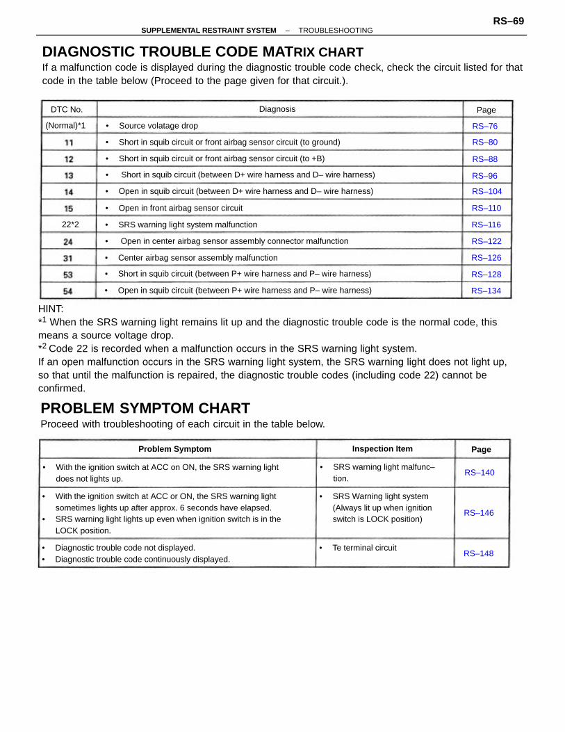
HINT:*1 When the SRS warning light remains lit up and the diagnostic trouble code is the normal code, thismeans a source voltage drop.*2 Code 22 is recorded when a malfunction occurs in the SRS warning light system.If an open malfunction occurs in the SRS warning light system, the SRS warning light does not light up,so that until the malfunction is repaired, the diagnostic trouble codes (including code 22) cannot beconfirmed.
DIAGNOSTIC TROUBLE CODE MAT RIX CHARTIf a malfunction code is displayed during the diagnostic trouble code check, check the circuit listed for thatcode in the table below (Proceed to the page given for that circuit.).
• With the ignition switch at ACC or ON, the SRS warning lightsometimes lights up after approx. 6 seconds have elapsed.
• SRS warning light lights up even when ignition switch is in theLOCK position.
PROBLEM SYMPTOM CHARTProceed with troubleshooting of each circuit in the table below.
• With the ignition switch at ACC on ON, the SRS warning lightdoes not lights up.
• Diagnostic trouble code not displayed.• Diagnostic trouble code continuously displayed.
• Open in squib circuit (between D+ wire harness and D– wire harness)
• Open in squib circuit (between P+ wire harness and P– wire harness)
• Short in squib circuit (between D+ wire harness and D– wire harness)
• Short in squib circuit (between P+ wire harness and P– wire harness)
• SRS Warning light system(Always lit up when ignitionswitch is LOCK position)
• Open in center airbag sensor assembly connector malfunction
• Short in squib circuit or front airbag sensor circuit (to ground)
• Short in squib circuit or front airbag sensor circuit (to +B)
• SRS warning light malfunc–tion.
• Center airbag sensor assembly malfunction
• SRS warning light system malfunction
• Open in front airbag sensor circuit
• Source volatage drop
• Te terminal circuit
Problem Symptom Inspection Item
(Normal)*1
DiagnosisDTC No.
RS–104
RS–140
RS–110
RS–122
RS–148
RS–134
RS–126
RS–116
RS–128
RS–146
RS–80
RS–76
RS–96
RS–88
Page
Page
22*2
–SUPPLEMENTAL RESTRAINT SYSTEM TROUBLESHOOTINGRS–69
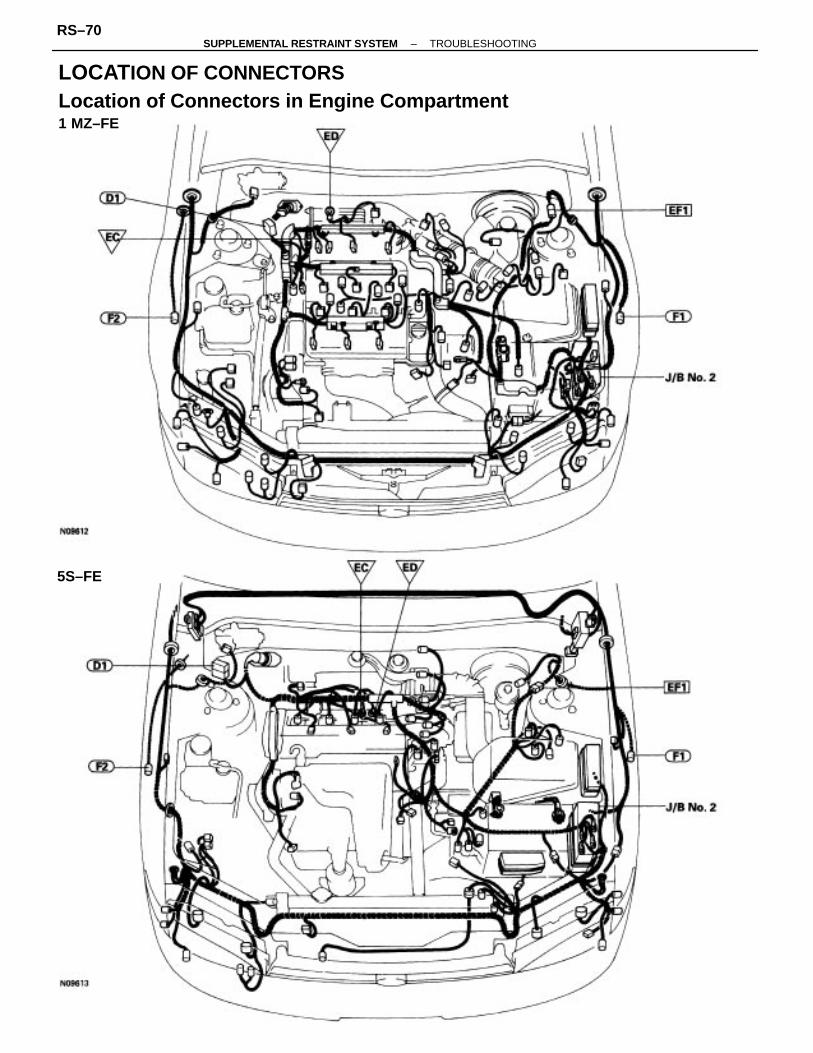
LOCATION OF CONNECTORSLocation of Connectors in Engine Compartment1 MZ–FE
5S–FE
–SUPPLEMENTAL RESTRAINT SYSTEM TROUBLESHOOTINGRS–70

–SUPPLEMENTAL RESTRAINT SYSTEM TROUBLESHOOTINGRS–71

Jl6 No. 2
–SUPPLEMENTAL RESTRAINT SYSTEM TROUBLESHOOTINGRS–72

Location of Connectors in Instrument Panel
–SUPPLEMENTAL RESTRAINT SYSTEM TROUBLESHOOTINGRS–73

JIB No. 1
–SUPPLEMENTAL RESTRAINT SYSTEM TROUBLESHOOTINGRS–74

J/B No. 3
–SUPPLEMENTAL RESTRAINT SYSTEM TROUBLESHOOTINGRS–75

CIRCUIT DESCRIPTIONThe supplemental restraint system is equipped with a voltage – increase circuit (DC–DC converter)in the center airbag sensor assembly in case the source voltage drops.When the battery voltage drops, the voltage – increase circuit (DC–DC converter) functions to in-crease the voltage of the supplemental restraint system to normal voltage.The diagnosis system malfunction display for this circuit is different to other circuits – when the SRSwarning light remains lit up and the diagnostic trouble code is a normal code, source voltage dropis indicated. Malfunction in this circuit is not recorded in the center airbag sensor assembly, andapprox. 10 seconds after the source voltage returns to normal, the SRS warning light automaticallygoes off.
Check diagnostic trouble code, andif a malfunction code is output,perform troubleshooting accordingto malfunction code. If a normalcode is output, replace center air–bag sensor assembly.
Does SRS warning light turnoff after approx.10 seconds?
Check battery and charging system(See CHARGING SYSTEM).
CIRCUIT INSPECTION
DIAGNOSTIC CHART
Source voltage drop.
Preparation.
Diagnosis
(Normal)
DTC (Normal) Source Voltage Drop
DTC No.
YES
–SUPPLEMENTAL RESTRAINT SYSTEM TROUBLESHOOTINGRS–76

DIAGNOSTIC CHARTWIRING DIAGRAM
–SUPPLEMENTAL RESTRAINT SYSTEM TROUBLESHOOTINGRS–77

(1) Turn ignition switch LOCK.(2) Disconnect battery negative (–) terminal ca–ble, and wait at least 90 seconds.(3) Connect battery negative (–) terminal cable.(4) Disconnect center airbag sensor assemblyconnector.(5) Turn ignition switch ON. But do not startengine.(6) Measure voltage at IG2 or ACC on connectorwire harness side of center airbag sensor as–sembly and operate electric system (defogger,wiper, headlight, heater blower, etc.).Voltage: 6 V – 11.5 V at IG2 and ACC.(7) Turn electric system switch OFF.(8) Turn ignition switch LOCK.(9) Disconnect battery negative (–) terminal ca–ble, and wait at least 90 seconds.(10) Remove voltmeter and connect center airbagsensor assembly connector.(11) Connect battery negative (–) terminal cable.
Turn ignition switch ON.Operate electric system checked in (5) andcheck that SRS warning light goes off.
Check diagnostic trouble code, and if a malfunc–tion code is output, perform troubleshootingaccording to malfunction code. If a normal codeis output, replace center airbag sensor assembly.
Check battery and charging system .
Does SRS warning light turn off?
INSPECTION PROCEDURES
Preparation.
Preparation
YES
Check
–SUPPLEMENTAL RESTRAINT SYSTEM TROUBLESHOOTINGRS–78

– MEMO –
–SUPPLEMENTAL RESTRAINT SYSTEM TROUBLESHOOTINGRS–79

CIRCUIT DESCRIPTION The squib circuit consists of the center airbag sensor assembly, spiral cable, steering wheel pad(squib), wire harness connector and front passenger airbag assembly(squib). It causes the airbag tooperate when the airbag operation conditions are satisfied.The front airbag sensor detects the deceleration force in a frontal collision and is located in frontfender on the left and right sides.For details of the function of each component, see FUNCTION OF COMPONENTS on page RS–10.Diagnostic trouble code 11 is recorded when ground short is detected in the squib circuit or front air-bag sensor circuit.
• Short circuit in squib wire harness (to ground).• Squib malfunction.• Short circuit in front airbag sensor +S, D+, D–, P+, P–, wire harness (to ground).• Front airbag sensor malfunction.• Short circuit between +S wire harness and –S wire harness of front airbag sensor.• Spiral cable malfunction.• Center airbag sensor assembly malfunction.
Diagnosis
DTC 11 Short in Squib Circuit or Front Airbag Sensor Circuit(to Ground)
DTC No.
–SUPPLEMENTAL RESTRAINT SYSTEM TROUBLESHOOTINGRS–80

From the results of the above inspection, themalfunctioning part can now be considered normal.To make sure of this, use the simulation method tocheck.
Repair or replace harness or connectorbetween front airbag sensor and centerairbag sensor assembly (See page RS–50).
Check D squib circuit. (Measure resistance betweenterminals D+, D– of center airbag assembly con–nector and body ground.)
Check P squib circuit. (Measure resistance betweenterminals P+, P– of center airbag assembly con–nector and body ground.)
Check front airbag sensor circuit. (Measure resis–tance between terminals +SR and –SR, +SL and –SLof center airbag sensor assembly connector.)
Check front airbag sensor circuit. (Measure resis–tance between terminals +SR, +SL of center airbagsensor assembly connector and body ground.)
Repair or replace harness or connectorbetween front airbag sensor and centerairbag sensor assembly (See page RS–50).
Replace center airbag sensor assembly.
Replace front passenger airbag assembly.
Check center airbag sensor assembly.
Go to step [9] on next page.
DIAGNOSTIC CHART
Replace steering wheel pad.Check D squib.
Check P squib.
on next page.
Preparation.
Go to step [10]
–SUPPLEMENTAL RESTRAINT SYSTEM TROUBLESHOOTINGRS–81

Repair or replace harness or connector betweenfront airbag sensor and center airbag sensorassembly (See page RS–50).
Repair or replace harness or connector betweencenter airbag sensor assembly and spiral cable.
DIAGNOSTIC CHART (Cont’d)
WIRING DIAGRAM
Repair or replace spiral cable.
Replace front airbag sensor.Check front airbag sensor.
Check spiral cable.
–SUPPLEMENTAL RESTRAINT SYSTEM TROUBLESHOOTINGRS–82

Disconnect center airbag sensor assembly con–nectors.Measure resistance between terminals +SR and–SR, +SL and –SL of harness side connector ofcenter airbag sensor assembly.
Resistance: 755 Ω – 885 Ω
(1) Disconnect battery negative (–) terminal cable,and wait at least 90 seconds.
(2) Remove steering wheel pad (See page RS–20).
(3) Disconnect connectors of front passengerairbag assembly. (See page RS–29)
Check front airbag sensor circuit. (Measure resistance between terminals+SR and –SR, +SL and –SL of center airbag sensor assembly connector.)
Store the steering wheel pad with the frontsurface facing upward.
INSPECTION PROCEDURE
Preparation.
Preparation
Go to step
Check
–SUPPLEMENTAL RESTRAINT SYSTEM TROUBLESHOOTINGRS–83
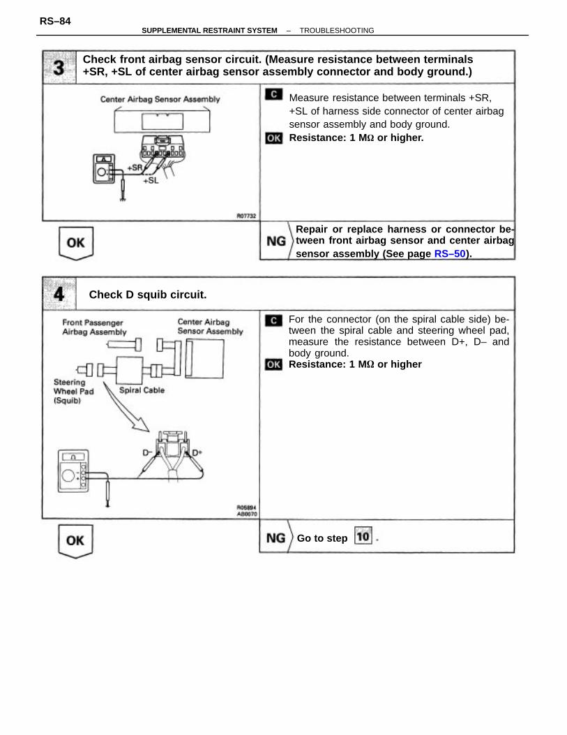
Check front airbag sensor circuit. (Measure resistance between terminals+SR, +SL of center airbag sensor assembly connector and body ground.)
Measure resistance between terminals +SR,+SL of harness side connector of center airbagsensor assembly and body ground.Resistance: 1 M or higher.
For the connector (on the spiral cable side) be-tween the spiral cable and steering wheel pad,measure the resistance between D+, D– andbody ground.Resistance: 1 M or higher
Repair or replace harness or connector be-tween front airbag sensor and center airbagsensor assembly (See page RS–50).
Check D squib circuit.
Go to step
–SUPPLEMENTAL RESTRAINT SYSTEM TROUBLESHOOTINGRS–84

(1) Connect connectors to center airbag sensorassembly.
(2) Using a service wire, connect D+ and D– onspiral cable side of connector between spiralcable and steering wheel pad.
(3) Using a service wire, connect P+ and P– oncenter airbag sensor assembly side of con-nec–tor between center airbag sensor assemblyand front passenger airbag assembly.
(4) Connect negative (–) terminal cable to battery,and wait at least 2 seconds.
(5) Turn ignition switch ACC or ON, and wait atleast 20 seconds.Clear malfunction code (See page RS–65).Turn ignition switch LOCK and wait at least20 seconds.
(1) Turn ignition switch ACC or ON and wait atleast 20 seconds.
(2) Using SST, connect terminals Tc and El ofDLC1 or DLC2.SST 09843–18020
(3) Check diagnostic trouble code.Diagnostic trouble code 11 is not output.
Codes other than code 11 may be output at thistime, but they are not relevant to this check.
For the connector (on the wiring harness connec-torside) between the wiring harness connector andfront passenger airbag assembly, measure the re–sistance between P+, P– and body ground.Resistance: 1 M or higher
Repair or replace harness of connector be-tween the center airbag sensor assembly andfront passenger airbag assembly.
Check center airbag sensor assembly.
Replace center airbag sensor assembly.
Check P squib circuit.
–SUPPLEMENTAL RESTRAINT SYSTEM TROUBLESHOOTINGRS–85

(1) Turn ignition switch LOCK.(2) Disconnect battery negative (–) terminal cable,
and wait at least 90 seconds.(3) Connect front passenger airbag assembly
(squib) connector.(4) Disconnect steering wheel pad (squib) con–
nector.(5) Connect negative (–) terminal cable to battery,
and wait at least 2 seconds.(6) Turn ignition switch ACC or ON, and wait at
least 20 seconds.Clear malfunction code. Turn ignition switchLOCK, and wait at least 20 seconds.
(1) Turn ignition switch ACC or ON, and wait atleast 20 seconds.
(2) Using SST, connect terminals Tc and El ofDLC1 or DLC2.
(3) Check diagnostic trouble code.Diagnostic trouble code 11 is not output.Codes other than code 11 may be output at thistime, but they are not relevant to this check.
(1) Turn ignition switch LOCK.(2) Disconnect battery negative (–) terminal cable,and wait at least 90 seconds.
(3) Connect steering wheel pad (squib) connec–tor.
(4) Connect negative (–) terminal cable to battery,and wait at least 2 seconds.
(5) Turn ignition switch ACC or ON, and wait atleast 20 seconds.Clear malfunction code. Turn ignition switchLOCK, and wait at least 20 seconds.(1) Turn ignition switch ACC or ON, and wait atleast 20 seconds.
(2) Using SST, connect terminals Tc and El ofDLC1 or DLC2.SST 09843–18020
(3) Check diagnostic trouble code.Diagnostic trouble code 11 is not output.Codes other than code 11 may be output at thistime, but they are not relevant to this check.
Replace front passenger airbag assembly.
Replace steering wheel pad.
Check D squib.
Check P squib.
–SUPPLEMENTAL RESTRAINT SYSTEM TROUBLESHOOTINGRS–86
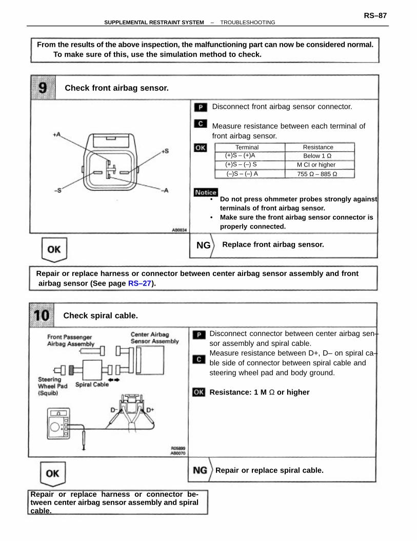
Disconnect connector between center airbag sen–sor assembly and spiral cable.Measure resistance between D+, D– on spiral ca–ble side of connector between spiral cable andsteering wheel pad and body ground.
Resistance: 1 M Ω or higher
From the results of the above inspection, the malfunctioning part can now be considered normal.To make sure of this, use the simulation method to check.
Repair or replace harness or connector between center airbag sensor assembly and front airbag sensor (See page RS–27).
• Do not press ohmmeter probes strongly againstterminals of front airbag sensor.
• Make sure the front airbag sensor connector isproperly connected.
Disconnect front airbag sensor connector.
Measure resistance between each terminal offront airbag sensor.
Repair or replace harness or connector be-tween center airbag sensor assembly and spiralcable.
Check front airbag sensor.
Repair or replace spiral cable.
Replace front airbag sensor.
Check spiral cable.
(+)S – (+)A
(+)S – (–) S M CI or higher
755 Ω – 885 Ω
Below 1 ΩResistanceTerminal
(–)S – (–) A
NG
–SUPPLEMENTAL RESTRAINT SYSTEM TROUBLESHOOTINGRS–87

CIRCUIT DESCRIPTIONThe squib circuit consists of the center airbag sensor assembly, spiral cable and the steering wheelpad (squib). It causes the airbag to deploy when the airbag deployment conditions are satisfied.The front airbag sensor detects the deceleration force in a frontal collision and is located in the frontfender on the left and right sides.For details of the function of each component, see FUNCTION OF COMPONENTS on page RS–10–Diagnostic trouble code 12 is recorded when a +B short is detected in the squib circuit or the front air-bag sensor circuit.
• Short circuit in squib wire harness (to +B).• Squib malfunction.• Short circuit in front airbag sensor +S wire harness (to +B).• Open circuit in RH and LH front airbag sensor harness.• Spiral cable malfunction.• Center airbag sensor assembly malfunction.
WIRING DIAGRAM
Diagnosis
DTC 12 Short in Squib Circuit (to B+)
DTC No.
–SUPPLEMENTAL RESTRAINT SYSTEM TROUBLESHOOTINGRS–88

Check front airbag sensor circuit.(Measure voltage between terminal +SR or +SL ofcenter airbag sensor assembly connector and bodyground.)
Check front airbag sensor circuit.(Measure resistance between terminals +SR and –SR, +SL and –SL of center airbag sensor assemblyconnector.)
From the results of the above inspection, themalfunctioning part can now be considered normal.To make sure of this, use the simulation method tocheck.
Check front airbag sensor circuit. (Measure voltagebetween terminals P+ and P’ of center airbagsensor assembly connector and body ground.)
Repair or replace harness or connectorbetween front airbag sensor and centerairbag sensor assembly. (See page RS–50).
Check front airbag sensor circuit. (Measure voltagebetween terminals D+ and D– of center airbagsensor assembly connector and body ground.)
Repair or replace harness or connectorbetween center airbag sensor assemblyand front airbag sensor (See page RS–50).
Repair or replace harness or connecter betweencenter airbag sensor assembly and spiral cable.
Replace front passenger airbag assem–bly.
Replace center airbag sensor assembly.Check center airbag sensor assembly.
DIAGNOSTIC CHART
Go to Code 15 (See page RS–110).
Repair or replace spiral cable.
Replace steering wheel pad.
Check spiral cable.
Check D squib.
Check P squib.
Preparation.
Go to step [9]
–SUPPLEMENTAL RESTRAINT SYSTEM TROUBLESHOOTINGRS–89

Disconnect center airbag sensor assembly con–nector.Measure resistance between terminals +SR and–SR, +SL and –SL of harness side connector ofcenter airbag sensor assembly.
Resistance: 755 – 885
(1) Disconnect battery negative H terminal cable,and wait at least 90 seconds.
(2) Remove steering wheel pad (See page RS–20).
(3) Disconnect connectors of front passengerairbag assembly. (See page RS–29)
Check front airbag sensor circuit. (Measure resistance between terminals+SR and –SR, +SL and –SL of center airbag sensor assembly connector.)
Store the steering wheel pad with the frontsurface facing upward.
INSPECTION PROCEDURES
Go to Code 15 (See page RS–110).
Preparation.
Preparation Check
–SUPPLEMENTAL RESTRAINT SYSTEM TROUBLESHOOTINGRS–90

(1) Connect negative (–) terminal cable to battery.(2) Turn ignition switch ON.Measure voltage between terminals +SR or +SLofharness side connector of center airbag sensorassembly and body ground.Voltage: Below 1 V
Check front airbag sensor circuit. (Measure voltage between terminal +SRor +SL of center airbag sensor assembly connector and body ground.)
Measure voltage at D+ on spiral cable side ofconnector between spiral cable and steeringwheelpad.Voltage: Below 1 V
Repair or replace harness or connector be-tween center airbag sensor assembly andfront airbag sensor (See page RS–50).
Check D squib circuit.
G o to step
–SUPPLEMENTAL RESTRAINT SYSTEM TROUBLESHOOTINGRS–91
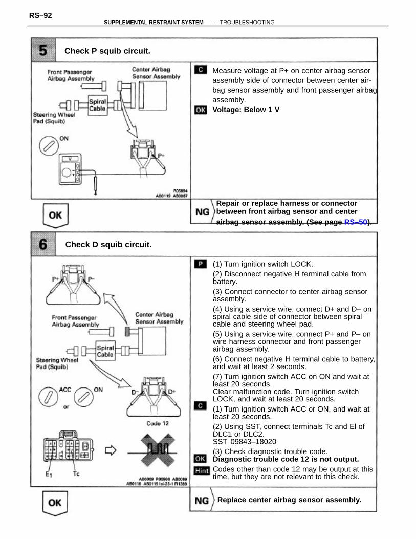
(1) Turn ignition switch LOCK.(2) Disconnect negative H terminal cable frombattery.(3) Connect connector to center airbag sensorassembly.(4) Using a service wire, connect D+ and D– onspiral cable side of connector between spiralcable and steering wheel pad.(5) Using a service wire, connect P+ and P– onwire harness connector and front passengerairbag assembly.(6) Connect negative H terminal cable to battery,and wait at least 2 seconds.(7) Turn ignition switch ACC on ON and wait atleast 20 seconds.Clear malfunction code. Turn ignition switchLOCK, and wait at least 20 seconds.(1) Turn ignition switch ACC or ON, and wait atleast 20 seconds.(2) Using SST, connect terminals Tc and El ofDLC1 or DLC2.SST 09843–18020(3) Check diagnostic trouble code.Diagnostic trouble code 12 is not output.Codes other than code 12 may be output at thistime, but they are not relevant to this check.
Measure voltage at P+ on center airbag sensorassembly side of connector between center air-bag sensor assembly and front passenger airbagassembly.Voltage: Below 1 V
Repair or replace harness or connector between front airbag sensor and center airbag sensor assembly. (See page RS–50).
Replace center airbag sensor assembly.
Check D squib circuit.
Check P squib circuit.
–SUPPLEMENTAL RESTRAINT SYSTEM TROUBLESHOOTINGRS–92

(1) Turn ignition switch LOCK.(2) Disconnect battery negative (–) terminal cable,and wait at least 90 seconds.(3) Connect front passenger airbag assembly(squib) connector.(4) Disconnect steering wheel pad (squib)connec-tor.(5) Connect negative (–) terminal cable to battery,and wait at least 2 seconds.(6) Turn ignition switch ACC or ON and wait atleast 20 seconds.Clear malfunction code. Turn ignition switchLOCK, and wait at least 20 seconds.(1) Turn ignition switch ACC or ON, and wait atleast 20 seconds.(2) Using SST, connect terminals Tc and El ofDLC1 or DLC2.(3) Check diagnostic trouble code.Diagnostic trouble code 12 is not output.Codes other than code 12 may be output at thistime, but they are not relevant to this check.
(1) Turn ignition switch LOCK.(2) Disconnect battery negative 1–) terminal cable,and wait at least 90 seconds.(3) Connect steering wheel pad (squib) connector.(4) Connect negative H terminal cable to battery,and bait at least 2 seconds.(5) Turn ignition switch, ACC or ON, and wait atleast 20 seconds.Clear malfunction code. Turn ignition switchLOCK, and wait at least 20 seconds.(1) Turn ignition switch ACC or ON, and wait atleast 20 seconds(2) Using SST, connect terminals Tc and El ofDLC1 or DLC2.SST 09843–18020(3) Check diagnostic trouble code.Diagnostic trouble code 12 is not output.Code other than code 12 may be output at thistime, but they are not relevant to this check.
Replace center airbag sensor assembly.
Replace steering wheel pad.
Check D squib.
Check P squib.
–SUPPLEMENTAL RESTRAINT SYSTEM TROUBLESHOOTINGRS–93

(1) Turn ignition switch LOCK.(2) Disconnect connector between center airbag
sensor assembly and spiral cable(3) Turn ignition switch ON.Measure voltage at D+ on spiral cable side ofcon–nector between spiral cable and steering wheelpad.Voltage: Below 1 V
From the results of the above inspection, the malfunctioning part can now be considered normal. To make sure of this, use the simulation method to check.
Repair or replace harness or connector between center airbag sensor assembly and spiralcable.
Repair or replace spiral cable.
Check spiral cable.
–SUPPLEMENTAL RESTRAINT SYSTEM SUPPTROUBLESHOOTINGRS–94

– MEMO –
–SUPPLEMENTAL RESTRAINT SYSTEM TROUBLESHOOTINGRS–95

CIRCUIT DESCRIPTIONThe squib circuit consists of the center airbag sensor assembly, spiral cable and the steering wheelpad (squib). It causes the airbag to deploy when the airbag deployment conditions are satisfied.For details of the function of each component, see FUNCTION OF COMPONENTS on page RS–10–Diagnostic trouble code 13 is recorded when a short is detected in the D+ wire harness and D– wireharness of the squib circuit.
• Short circuit between D+ wire harness and D– wire harness of squib.• Squib malfunction.• Spiral cable malfunction.• Center airbag sensor assembly malfunction.
From the results of the above inspection,the malfunctioning part can now be con–sidered normal. To make sure of this, usethe simulation method to check.
Replace center airbag sensor as–sembly.
Check center airbag sensor assembly.
Replace steering wheel pad.
DIAGNOSTIC CHART
Check D squib circuit.
Check D squib.
on next page.
Preparation.
Go to step
Diagnosis
DTC 13 Short in Squib Circuit (Between D+ WireHarness and D – Wire Harness)
DTC No.
–SUPPLEMENTAL RESTRAINT SYSTEM TROUBLESHOOTINGRS–96

From the results of the above inspection,the malfunctioning part can now be con–sidered normal. To make sure of this, usethe simulation method to check.
Repair or replace harness or con–nector between center airbag sen–sor assembly and spiral cable.
Check harness between center airbag sen–sor assembly and spiral cable.
Replace center airbag sensor as–sembly.
DIAGNOSTIC CHART (Cont’d)
Check center airbag sensor assembly.
Repair or replace spiral cable.
WIRING DIAGRAM
Check spiral cable.
–SUPPLEMENTAL RESTRAINT SYSTEM TROUBLESHOOTINGRS–97
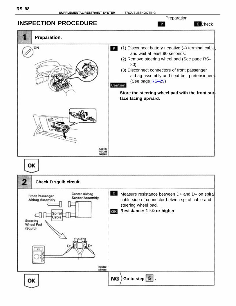
(1) Disconnect battery negative (–) terminal cable,and wait at least 90 seconds.
(2) Remove steering wheel pad (See page RS–20).
(3) Disconnect connectors of front passengerairbag assembly and seat belt pretensioners.(See page RS–29)
Measure resistance between D+ and D– on spiralcable side of connector betwen spiral cable andsteering wheel pad.Resistance: 1 k or higher
Store the steering wheel pad with the front sur-face facing upward.
INSPECTION PROCEDURE
Check D squib circuit.
Preparation
Preparation.
Go to step
Check
–SUPPLEMENTAL RESTRAINT SYSTEM TROUBLESHOOTINGRS–98
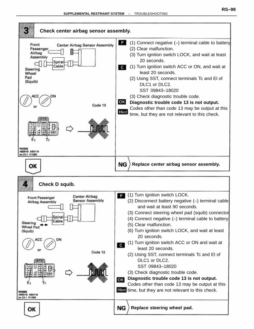
(1) Turn ignition switch LOCK.(2) Disconnect battery negative (–) terminal cable,
and wait at least 90 seconds.(3) Connect steering wheel pad (squib) connector.(4) Connect negative (–) terminal cable to battery.(5) Clear malfunction.(6) Turn ignition switch LOCK, and wait at least
20 seconds.(1) Turn ignition switch ACC or ON and wait at
least 20 seconds.(2) Using SST, connect terminals Tc and El of
DLC1 or DLC2.SST 09843–18020
(3) Check diagnostic trouble code.Diagnostic trouble code 13 is not output.Codes other than code 13 may be output at thistime, but they are not relevant to this check.
(1) Connect negative (–) terminal cable to battery.(2) Clear malfunction.(3) Turn ignition switch LOCK, and wait at least
20 seconds.(1) Turn ignition switch ACC or ON, and wait at
least 20 seconds.(2) Using SST, connect terminals Tc and El of
DLC1 or DLC2.SST 09843–18020
(3) Check diagnostic trouble code.Diagnostic trouble code 13 is not output.Codes other than code 13 may be output at thistime, but they are not relevant to this check.
Check center airbag sensor assembly.
Replace center airbag sensor assembly.
Replace steering wheel pad.
Check D squib.
–SUPPLEMENTAL RESTRAINT SYSTEM TROUBLESHOOTINGRS–99

(1) Disconnect connector between center airbagsensor assembly and spiral cable.
(2) Release airbag activation prevention mecha–nism on center airbag sensor assembly sideof spiral cable connector (See page RS–102).
Measure resistance between D+ and D– on spiralcable side of connector between spiral cableand steering wheel pad.
Resistance: 1 M or higher
(1) Disconnect center airbag sensor assemblyconnector.
(2) Release airbag activation prevention mecha–nism on center airbag sensor assembly con–nector (See page RS–50).
Measure resistance between D+ and D– on cen-ter airbag sensor assembly side of connector be-tween center airbag sensor assembly and spiralcable.Resistance: 1 M or higher
From the results of the above inspection, the malfunctioning part can now be considered nor-mal. To make sure of this, use the simulation method to check.
Check harness between center airbag sensor assembly and spiral cable.
Repair or replace harness or connector be-tween center airbag sensor assembly andspiral cable.
Repair or replace spiral cable.
Check spiral cable.
–SUPPLEMENTAL RESTRAINT SYSTEM TROUBLESHOOTINGRS–100

Connect center airbag sensor assembly connec-tor.Measure resistance between D+ and D– on cen-ter airbag sensor assembly side of connectorbetween center airbag sensor assembly and spi-ral cable.Resistance: 1 KM Ω or higher
From the results of the above inspection, the malfunctioning part can now be considered nor-mal. To make sure of this, use the simulation method to check.
7. Check center airbag sensor assembly.
Replace center airbag sensor assembly.
Center AirbagSensor Assembly
Front PassengerAirbag Assembly
Steering WheelPad (Squib)
SpiralCable
805905AB0068
0P
–SUPPLEMENTAL RESTRAINT SYSTEM SUPPLEMENTAL RESTRAINT SYSTEMTROUBLESHOOTING
RS–101

RELEASE METHOD OF AIRBAG ACTIVAT ION PREVENTION MECHANISMAn airbag activation prevention mechanism is built into the connector for the squib circuit of thesupplemental restraint system. When release of the airbag activation prevention mechanism is directedin the troubleshooting procedure, as shown in the illustration of the connector T and 0 below, insertpaper which is the same thickness as the male terminal, between the terminal and the short spring
CAUTION:
• NEVER RELEASE the airbag activation prevention mechanism on the steering wheel pad connector.NOTICE:
• Do not release the airbag activation prevention mechanism unless specifically directed by thetroubleshooting procedure.
• If the paper inserted is too thick the terminal and short spring may be damaged, so always use paperthe same thickness as the male terminal.
–SUPPLEMENTAL RESTRAINT SYSTEM TROUBLESHOOTINGRS–102

– MEMO –
–SUPPLEMENTAL RESTRAINT SYSTEM TROUBLESHOOTINGRS–103

CIRCUIT DESCRIPTIONThe squib circuit consists of the center airbag sensor assembly, spiral cable and the steering wheel pad (squib). It causes the airbag to deploy when the airbag deployment conditions are satisfied.For details of the function of each component, see FUNCTION OF COMPONENTS on page RS–10.Diagnostic trouble code 14 is recorded when an open is detected in the squib circuit.
• Open circuit in D+ wire harness or D‘ wire harness of squib.• Squib malfunction.• Spiral cable malfunction.• Center airbag sensor assembly malfunction.
Diagnosis
DTC 14 Open in D Squib Circuit
DTC No.
–SUPPLEMENTAL RESTRAINT SYSTEM TROUBLESHOOTINGRS–104

From the results of the above inspection,the malfunctioning part can now be con–sidered normal. To make sure of this, usethe simulation method to check.
Repair or replace harness or con–nector between center airbag sen–sor assembly and spiral cable.
Check harness between center airbag sen–sor assembly and spiral cable.
Replace center airbag sensor as–sembly.
WIRING DIAGRAM
Check center airbag sensor assembly.
Repair or replace spiral cable.
Replace steering wheel pad.
DIAGNOSTIC CHART
Check D squib circuit.
Check spiral cable.
Check D squib.
Preparation.
Go to step
–SUPPLEMENTAL RESTRAINT SYSTEM TROUBLESHOOTINGRS–105

Disconnect center airbag sensor assembly con–nectors.
Measure resistance between D+ and D– on spiralcable side of connector between spiral cable andsteering wheel pad.Resistance: Below 1
(1) Disconnect battery negative (–) terminal cable,and wait at least 90 seconds.
(2) Remove steering wheel pad (See page RS–20).(3) Disconnect connectors of front passenger
airbag assembly. (See page RS–29)
Store the steering wheel pad with the frontsurface facing upward.
INSPECTION PROCEDURE
Check D squib circuit.
Preparation.
Preparation
Go to step
Check
–SUPPLEMENTAL RESTRAINT SYSTEM TROUBLESHOOTINGRS–106

Disconnect connector between center airbag sen–sor assembly and spiral cable.
Measure resistance between D+ and D– on spiralcable side of connector between spiral cable andsteering wheel pad.Resistance: Below 1 Ω
Measure resistance between D+ and D– on centerairbag sensor assembly side of connector be-tweencenter airbag sensor assembly and spiral cable.Resistance: Below 1 Ω
Check harness between center airbag sensor assembly and spiral cable.
Repair or replace harness or connector between center airbag sensor assembly and spiral cable.
Repair or replace spiral cable.
Check spiral cable.
–SUPPLEMENTAL RESTRAINT SYSTEM TROUBLESHOOTINGRS–107

(1) Connect connector to center airbag sensorconnector.(2) Connect connector between center airbagsensor assembly and spiral cable.(3) Using a service wire, connect D+ and D– onspiral cable side of connector between spiralcable and steering wheel pad.(4) Connect negative (–) terminal cable to battery,and wait at least 2 seconds.(5) Turn ignition switch ACC on ON and wait atleast 20 seconds.Clear malfunction code. Turn ignition switchLOCK, and wait at least 20 seconds.(1) Turn ignition switch ACC or ON, and wait atleast 20 seconds.(2) Using SST, connect terminals Tc and El ofDLC1 or DLC2.SST 09843–18020(3) Check diagnostic trouble code.Diagnostic trouble code 14 is not output.Codes other than code 14 may be output at thistime, but they are not relevant to this check.
(1) Turn ignition switch LOCK.(2) Disconnect battery negative H terminal cable,and wait at least 90 seconds.(3) Connect steering wheel pad (squib) con–nector.(4) Connect negative (–y terminal cable to bat–tery, and wait at least 2 seconds.(5) Turn ignition switch ACC or ON, and wait atleast 20 seconds.(6) Clear malfunction code. Turn ignition switchLOCK, and wait at least 20 seconds.Turn ignition switch ACC or ON, and wait atleast 20 seconds(2) Using SST, connect terminals Tc and El ofDLC1 or DLC2.SST 09843–18020(3) Check diagnostic trouble code.Diagnostic trouble code 14 is not output.Code other than code 14 may be output at thistime, but they are not relevant to this check.
From the results of the above inspection, the malfunctioning part can now be considered nor-mal. To make sure of this, use the simulation method to check.
Check center airbag sensor assembly.
Replace center airbag sensor assembly.
Replace steering wheel pad.
Check D squib.
–SUPPLEMENTAL RESTRAINT SYSTEM TROUBLESHOOTINGRS–108

– MEMO –
–SUPPLEMENTAL RESTRAINT SYSTEM TROUBLESHOOTINGRS–109

CIRCUIT DESCRIPTIONThe front airbag sensor detects the deceleration force in a frontal collision and is located in the frontfender on the left and right sides.For details of the function of each component, see FUNCTION OF COMPONENTS on pageRS–10.Diagnostic trouble code 15 is recorded when an open is detected in the front airbag sensor circuit.
NOTICE: The front airbag sensor connector is equipped with an electrical connection check mech–anism for the purpose of detecting an open in the front airbag sensor (See page RS–13). This mech–anism is constructed so that when the terminals of the front airbag sensor have been connected(when the connector housing lock is in the locked condition), the connection detection pin on thewire harnessside connects with the terminals for diagnosis use on the sensor side. If the connector is not properlyconnected, the diagnosis system, may detect only a malfunction code, even though the supplemen-tal restraint system is functioning normally. When connecting the front airbag sensor connector,make sure it is connected properly. If diagnostic trouble code 15 is displayed after the front airbagsensor connector has been connected, check again that it is properly connected.
• Open circuit in +S wire harness or –S wire harness of front airbag sensor.• Short circuit in front airbag sensor +S wire harness (to +B).• Front airbag sensor malfunction.• Malfunction of electrical connection check mechanism of front airbag sensor.• Center airbag sensor assembly malfunction.
WIRING DIAGRAM
Diagnosis
DTC 15 Open in Front Airbag Sensor Circuit
DTC No.
–SUPPLEMENTAL RESTRAINT SYSTEM TROUBLESHOOTINGRS–110

From the results of the above inspection,the malfunctioning part can now be con–sidered normal. To make sure of this, usethe simulation method to check.
Check front airbag sensor circuit(Measure resistance between terminals +SR and –SR, +SL and –SL of center airbag sensorassembly connector).
Check front airbag sensor circuit(Measure voltage between terminal +SR or+SL. and of center airbag assembly con–nector and body ground).
Repair or replace harness or con–nector between center airbag sen–sor. assembly and front airbagsesor. (See page RS–50).
Repair or replace harness or con–nector between center airbag sen–sor assembly and front airbagsensor. (See page RS–50).
Replace front airbag sensor connector (Seepage RS–50).
Check harness between center airbag sen–sor assembly and front airbag sensor.
Replace center airbag sensor as–sembly.
Check center airbag sensor assembly.
Replace front airbag sensor.
DIAGNOSTIC CHART
Check front airbag sensor.
Preparation.
Go to step
–SUPPLEMENTAL RESTRAINT SYSTEM TROUBLESHOOTINGRS–111
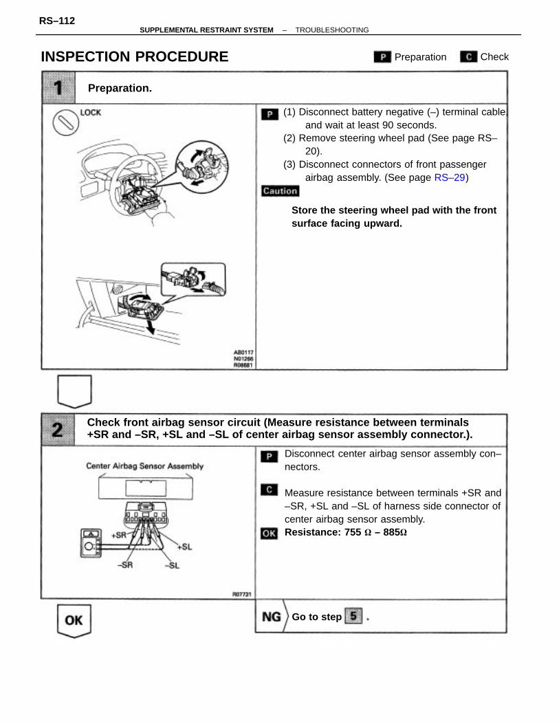
Disconnect center airbag sensor assembly con–nectors.
Measure resistance between terminals +SR and–SR, +SL and –SL of harness side connector ofcenter airbag sensor assembly.Resistance: 755 – 885
(1) Disconnect battery negative (–) terminal cable,and wait at least 90 seconds.
(2) Remove steering wheel pad (See page RS–20).
(3) Disconnect connectors of front passengerairbag assembly. (See page RS–29)
Check front airbag sensor circuit (Measure resistance between terminals+SR and –SR, +SL and –SL of center airbag sensor assembly connector.).
Store the steering wheel pad with the frontsurface facing upward.
INSPECTION PROCEDURE
Preparation.
Preparation
Go to step
Check
–SUPPLEMENTAL RESTRAINT SYSTEM TROUBLESHOOTINGRS–112

(1) Turn ignition switch LOCK.(2) Disconnect negative (–) terminal cable frombattery.(3) Connect connector to center airbag sensorassembly.(4) Using a service wire, connect D+ and D– onspiral cable side of connector between spiralcable and steering wheel pad.(5) Using a service wire, connect P+ and P– onwire harness connector side of connector be–tween wire harness connector and front pas–senger airbag. .(6) Connect negative (–) terminal cable to battery,and wait at least 2 seconds.(7) Turn ignition switch ACC or ON and wait atleast 20 seconds.Clear malfunction code. Turn ignition switchLOCK and wait at least 20 seconds.(1) Turn ignition switch ACC or ON and wait atleast 20 seconds.(2) Using SST, connect terminals Tc and El ofDLC1 or DLC2.SST 09843–18020(3) Check diagnostic trouble code.Diagnostic trouble code 15 is not output.Codes other than code 15 may be output at thistime, but they are not relevant to this check.
(1) Connect negative H terminal cable to battery.(2) Turn ignition SWitch ON.Measure voltage between terminals +SR or +SLofharness side connector of center airbag sensorassembly and body ground.
Voltage: Below 1 V
Check front airbag sensor circuit. (Measure voltage between terminal +SRor +SL of center airbag sensor assembly connector and body ground.)
From the results of the above inspection, the malfunctioning part can now be considered nor-mal. To make sure of this, use the simulation method to check.
Repair or replace harness or connector be-tween center airbag sensor assembly andfront airbag sensor (See page RS–50).
Check center airbag sensor assembly.
Replace center airbag sensor assembly.
–SUPPLEMENTAL RESTRAINT SYSTEM TROUBLESHOOTINGRS–113

(1) Disconnect center airbag sensor assemblyconnectors.
(2) Using service wires, connect +SR and –SR,+SL and –SL on the wire harness side of thecenter airbag sensor assembly connectors.
Measure resistance between terminals +SR and–SR, +SL and –SL of harness side connector offront airbag sensor.
• Lightly touch ohmmeter probes at positionshown in illustration.
• Make sure the front airbag sensor connector isproperly connected.Resistance: Below 1
Check harness between center airbag sensor assembly and front airbagsensor.
• Do not press ohmmeter probes too stronglyagainst terminals of front airbag sensor.
• Make sure the front airbag sensor connector isproperly connected.
Disconnect front airbag sensor connector.Measure resistance between each terminal offrontairbag sensor.
Repair or replace harness or connector be-tween center airbag sensor assembly andfront airbag sensor (See page RS–50).
Replace front airbag sensor connector (See page RS–50).
Check front airbag sensor.
Replace front airbag sensor.
ResistanceTerminal
–SUPPLEMENTAL RESTRAINT SYSTEM TROUBLESHOOTINGRS–114

– MEMO –
–SUPPLEMENTAL RESTRAINT SYSTEM TROUBLESHOOTINGRS–115

CIRCUIT DESCRIPTIONThe SRS warning light is located on the cluster finish panel.when the SRS is normal, the SRS warning light lights up for approx.6 seconds after the ignition switchis turned from LOCK position to ACC or ON position, and then turns off automatically.If there is a malfunction in the SRS, the SRS warning light lights up to inform the driver of theabnormality.When terminals Tc and E1of the DLC1 or DLC2 are connected, the diagnostic trouble code is dis-playedby the blinking of the SRS warning light.The SRS warning light circuit is equipped with an electrical connection check mechanism which de-tectswhen the connector to the center airbag sensor assembly is not properly connected.If the connector to the center airbag sensor assembly is not properly connected, the SRS warning lightwill not light up.Diagnostic trouble code 22 is recorded when a malfunction occurs in the SRS warning light system. Ifan OPEN malfunction occurs in the SRS warning light system, the SRS warning light does not light up,so that until the malfunction is repaired, the diagnostic trouble codes (including code 22f cannot beconfirmed.
• Open circuit in SRS warning light system.• Center– airbag sensor assembly malfunction.
Diagnosis
DTC 22 SRS Warning Light System Malfunction
DTC No.
–SUPPLEMENTAL RESTRAINT SYSTEM TROUBLESHOOTINGRS–116
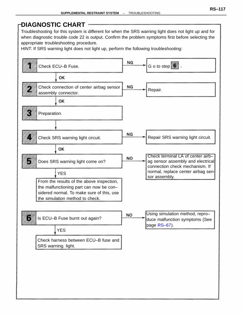
DIAGNOSTIC CHARTTroubleshooting for this system is different for when the SRS warning light does not light up and forwhen diagnostic trouble code 22 is output. Confirm the problem symptoms first before selecting theappropriate troubleshooting procedure.HINT: If SRS warning light does not light up, perform the following troubleshooting:
From the results of the above inspection,the malfunctioning part can now be con–sidered normal. To make sure of this, usethe simulation method to check.
Check terminal LA of center airb–ag sensor assembly and electricalconnection check mechanism. Ifnormal, replace center airbag sen-sor assembly.
Using simulation method, repro–duce malfunction symptoms (Seepage RS–67).
Check connection of center airbag sensorassembly connector.
Check harness between ECU–B fuse andSRS warning. light.
Does SRS warning light come on?
Repair SRS warning light circuit.Check SRS warning light circuit.
Is ECU–B Fuse burnt out again?
Check ECU–B Fuse.
Preparation.
G o to step
Repair.
YES
YES
–SUPPLEMENTAL RESTRAINT SYSTEM TROUBLESHOOTINGRS–117

DIAGNOSTIC CHARTHINT: If diagnostic trouble code 22 is output, perform the following troubleshooting:NO Using simulation m
Using simulation method, repro–duce malfunction symptoms (Seepage RS–67).
Is diagnostic trouble code 22 output again?
Replace center airbag sensor assembly.
WIRING DIAGRAM
YES
–SUPPLEMENTAL RESTRAINT SYSTEM TROUBLESHOOTINGRS–118

Remove ECU–B fuse.
Check continuity of ECU–13 fuse.Continuity
• Fuse may be burnt out even if it appears to beOK during visual inspection.
• If fuse is OK, instal it.
INSPECTION PROCEDURESHINT: IF SRS warning light does not light up, perform the following troubleshooting:
(1) Disconnect negative (–) terminal cable fromthe battery, and wait at least 90 seconds.
(2) Remove steering wheel pad (See page RS–20).(3) Disconnect connector of front passengerairbag assembly. (See page RS–29).
Check connection of center airbag sensor assembly connector.
Store the steering wheel pad with the frontsurface facing upward.
Check ECU–B fuse.
Preparation.
Go to step
Repair.
CheckPreparation
–SUPPLEMENTAL RESTRAINT SYSTEM TROUBLESHOOTINGRS–119

(1) Disconnect negative H terminal cable fromthe battery.
(2) Connect center airbag sensor assembly con–nector.(3) Connect negative 1–y terminal cable to battery,and wait at least 2 seconds.
(4) Turn ignition switch ACC or ON.
Check operation of SRS warning light.
SRS warning light comes on.
(1) Disconnect center airbag sensor assemblyconnector.
(2) Connect negative (–) terminal cable to battery.
(3) Turn ignition switch ACC or ON.Measure voltage LA terminal of harness side con–nector of center airbag sensor assembly.
Voltage: Battery positive voltage
From the results of the above inspection, the malfunctioning part can now be considered normal. To make sure of this, use the simulation method to check.
Check terminal LA of center airbag sensor assem-bly and electrical connection check mechanism.If normal, replace center airbag sensor assembly.
Check harness between ECU–B fuse and SRS warninglight.
Using simulation method, reproduce malfunc-tion symptoms (See page RS–67).
Is new ECU–B fuse burnt out again?
Does SRS warning light come on?
Check SRS warning light circuit.
Repair SRS warning light circuit.
YES
YES
–SUPPLEMENTAL RESTRAINT SYSTEM TROUBLESHOOTINGRS–120
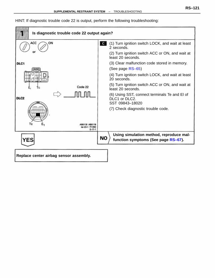
(1) Turn ignition switch LOCK, and wait at least2 seconds.
(2) Turn ignition switch ACC or ON, and wait atleast 20 seconds.(3) Clear malfunction code stored in memory.(See page RS–65)
(4) Turn ignition switch LOCK, and wait at least20 seconds.
(5) Turn ignition switch ACC or ON, and wait atleast 20 seconds.(6) Using SST, connect terminals Te and El ofDLC1 or DLC2.SST 09843–18020(7) Check diagnostic trouble code.
HINT: If diagnostic trouble code 22 is output, perform the following troubleshooting:
Using simulation method, reproduce mal-function symptoms (See page RS–67).
Is diagnostic trouble code 22 output again?
Replace center airbag sensor assembly.
YES
–SUPPLEMENTAL RESTRAINT SYSTEM TROUBLESHOOTINGRS–121

The center airbag sensor assembly detects partial connection of connectors.For details of the function of each component, see FUNCTION OF COMPONENTS on page RS–10.When the center airbag sensor assembly detects an open in the electrical connection check mecha-nism of the center airbag sensor connector or in the center airbag sensor circuit, trouble code 24 is re-corded.
• Malfunction of electrical connection check mechanism of center airbag sensor assembly connectors.• Center airbag sensor assembly malfunction.
Diagnosis
DTC 24 Open in Center Airbag Sensor AssemblyConnectors Malfunction
DTC No.
CIRCUIT DESCRIPTION
–SUPPLEMENTAL RESTRAINT SYSTEM TROUBLESHOOTINGRS–122

From the results of the above inspection, themalfunctioning part can now be considerednormal. To make sure of this, use the simula–tion method to check.
Are connectors of center airbag sensorassembly properly connected?
Check unfitting detector pin in the centerairbag sensor assembly connector.
Repair or replace center airbag sensorassembly connector.
Replace center airbag sensor asse–mbly.Check center airbag sensor assembly.
DIAGNOSTIC CHART
Connect connectors.
–SUPPLEMENTAL RESTRAINT SYSTEM TROUBLESHOOTINGRS–123

(1) Disconnect negative (–) terminal cablefrom battery.
(2) Disconnect center airbag sensor assembly.Test for continuity.
Continuity exists.
From the results of the above inspection, the malfunctioning part can now be considered normal. To make sure of this, use the simulation method to check.
Check unfitting detector pin in the center airbag sensor assemblyconnector.
Are connector of center airbag sensor assembly properly connected?
Repair or replace center airbagsensor assembly connector.
INSPECTION PROCEDURE
Connect connectors.
Preparation Check
–SUPPLEMENTAL RESTRAINT SYSTEM TROUBLESHOOTINGRS–124

(1) Disconnect negative (–y terminal cable frombattery.
(2) Connect center airbag sensor assembly.
(3) Connect negative H terminal cable to battery.(4) Turn ignition switch ACC or ON.
Check diagnostic trouble code.
Diagnostic trouble code 24 is not output.
From the results of the above inspection, the malfunctioning part can now beconsidered normal. To make sure of this, use the simulation method to check.
Check center– airbag sensor assembly.
Replace center airbag sensor assembly.
–SUPPLEMENTAL RESTRAINT SYSTEM TROUBLESHOOTINGRS–125

CIRCUIT DESCRIPTIONThe center airbag sensor assembly consists of a center airbag sensor, safing sensor, ignition controland drive circuit, diagnosis circuit, etc.It receives signals from the airbag sensors, judges whether or not the airbag must be deploy, anddiagnosis system malfunction.Diagnostic trouble code 31 is recorded with occurrence of a malfunction in the center airbag sensorassembly is detected.
DIAGNOSTIC CHARTHINT: When a malfunction code other than code 31 is displayed at the same time, first repair themalfunction indicated by the malfunction code other than code 31.
Using simulation method, repro–duce malfunction symptoms (SeeINTRODUCTION).
Is diagnostic trouble code 31 output again?
Replace center airbag sensor assembly.
• Center airbag sensor assembly malfunction.
Diagnosis
DTC 31 Center Airbag Sensor Assembly Malfunction
DTC No.
YES
NO
–SUPPLEMENTAL RESTRAINT SYSTEM TROUBLESHOOTINGRS–126
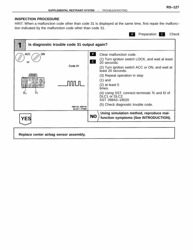
Clear malfunction code.(1) Turn ignition switch LOCK, and wait at least20 seconds.(2) Turn ignition switch ACC or ON, and wait atleast 20 seconds.(3) Repeat operation in step(1) and(2) at least 5times.(4) Using SST, connect terminals Tc and El ofDLC1 or DLC2.SST 09843–18020(5) Check diagnostic trouble code.
INSPECTION PROCEDUREHINT: When a malfunction code other than code 31 is displayed at the same time, first repair the malfunc–tion indicated by the malfunction code other than code 31.
Using simulation method, reproduce mal-function symptoms (See INTRODUCTION).
Is diagnostic trouble code 31 output again?
Replace center airbag sensor assembly.
YES
Preparation Check
–SUPPLEMENTAL RESTRAINT SYSTEM TROUBLESHOOTINGRS–127
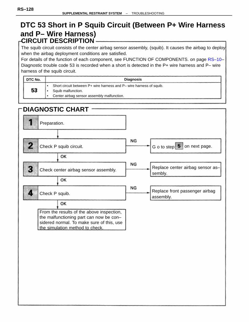
CIRCUIT DESCRIPTIONThe squib circuit consists of the center airbag sensor assembly, (squib). It causes the airbag to deploywhen the airbag deployment conditions are satisfied.For details of the function of each component, see FUNCTION OF COMPONENTS. on page RS–10–Diagnostic trouble code 53 is recorded when a short is detected in the P+ wire harness and P– wireharness of the squib circuit.
• Short circuit between P+ wire harness and P– wire harness of squib.• Squib malfunction.• Center airbag sensor assembly malfunction.
From the results of the above inspection,the malfunctioning part can now be con–sidered normal. To make sure of this, usethe simulation method to check.
Replace front passenger airbagassembly.
Replace center airbag sensor as–sembly.
Check center airbag sensor assembly.
DIAGNOSTIC CHART
Check P squib circuit.
Check P squib.
on next page.
Preparation.
G o to step
Diagnosis
DTC 53 Short in P Squib Circuit (Between P+ Wire Harnessand P– Wire Harness)
DTC No.
–SUPPLEMENTAL RESTRAINT SYSTEM TROUBLESHOOTINGRS–128
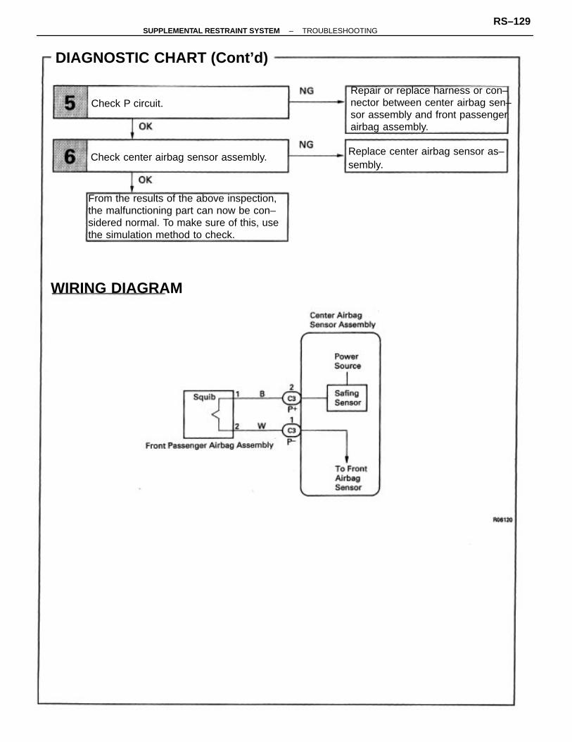
From the results of the above inspection,the malfunctioning part can now be con–sidered normal. To make sure of this, usethe simulation method to check.
Repair or replace harness or con–nector between center airbag sen–sor assembly and front passengerairbag assembly.
Replace center airbag sensor as–sembly.
DIAGNOSTIC CHART (Cont’d)
Check center airbag sensor assembly.
WIRING DIAGRAM
Check P circuit.
–SUPPLEMENTAL RESTRAINT SYSTEM TROUBLESHOOTINGRS–129

(1) Disconnect battery negative H terminal cable,and wait at least 90 seconds.t2y Remove steering wheel pad (See page RS–20).(3) Disconnect connectors of front passengerairbag assembly (See page RS–29).
For the connector (on the center airbag sensorassembly side) between the center airbag sensorassembly and front passenger airbag assembly,measure the resistance between P+ and P’.Resistance: 1 k or higher
Store the steering wheel pad with the frontsurfacefacing upward.
INSPECTION PROCEDURE
Check Psquib circuit.
Preparation.
Preparation
Go to step
Check
–SUPPLEMENTAL RESTRAINT SYSTEM TROUBLESHOOTINGRS–130

(1) Connect negative (–) terminal cable to battery,and wait at least 2 seconds.(2) Clear malfunction code stored in memory(See page RS–65).
(3) Turn ignition switch LOCK, and wait at least20 seconds.(1) Turn ignition switch ACC or ON and wait atleast 20 seconds.
(2) Using SST, connect terminals Tc and El ofD LC 1 or D LC2 .SST 09843–18020
(3) Check diagnostic trouble code.Diagnostic trouble code 53 is not output.Codes other than code 53 may be output at thistime, but they are not relevant to this check.
Check center airbag sensor assembly.
Replace center airbag sensor assembly.
–SUPPLEMENTAL RESTRAINT SYSTEM TROUBLESHOOTINGRS–131

(1)Turn ignition switch–LOCK.(2) Disconnect battery negative (–) terminal cableand wait at least 90 seconds.
(3) Connect front passenger airbag assemblyconnector.
(4) Connect negative H terminal cable to battery,and wait at least 2 seconds.(5)Clear malfunction code (See page RS–65).
(6) Turn ignition switch ACCor ON, and wait at least 20 seconds.(1)Turn ignition switch ACC or ON and wait atleast 20 seconds(2)Using SSt, connect terminals Tc and E1 ofDLC1 or DLC2.SST 09843–18020(3) Check diagnostic trouble code.
Diagnostic trouble code 53 is not output.
Codes other than code 54 may be output at thistime, but they are not relevant to this check.
From the results of the above inspection, the malfunctioning part can now be considered nor-mal. To make sure of this, use the simulation method to check.
Replace front passenger airbag assembly.
Check P squib.
–SUPPLEMENTAL RESTRAINT SYSTEM TROUBLESHOOTINGRS–132

(1) Disconnect center airbag sensor assemblyconnector.
(2) Release airbag activation prevention mecha–nism on center airbag sensor assembly con–nector (See page RS–102).For the connector (on the center airbag sensor as–sembly side) between the center airbag sensorassembly and front passenger airbag assembly,measure the resistance between P+ and P–.
Resistance: 1 k or higher
Connect center airbag sensor assembly connec–tor.For the connector (on the center airbag sensorassembly side) between the center airbag sensorassembly and front passenger airbag assembly,measure the resistance between P+ and P–.Resistance: 1 k or higher
From the results of the above inspection, the malfunctioning part can now be considerednormal. To make sure of this, use the simulation method to check.
Repair or replace harness or connector be-tween center airbag sensor assembly andfront passenger airbag assembly.
Check center airbag sensor assembly.
Replace center airbag sensor assembly.
Check P circuit
–SUPPLEMENTAL RESTRAINT SYSTEM TROUBLESHOOTINGRS–133

CIRCUIT DESCRIPTIONThe squib circuit consists of the center airbag sensor assembly, wiring harness connector and frontpassenger airbag assembly. It causes the airbag to deploy when the airbag deployment conditions are satisfied. For details of the function of each component, see FUNCTION OF COMPONENTS on page RS–10.Diagnostic trouble code 54 is recorded when an open is detected in the squib circuit.
• Open circuit in P+ wire harness and P– wire harness of squib.• Squib malfunction.• Center airbag sensor assembly malfunction.
Diagnosis
DTC 54 Open in P Squib Circuit
DTC No.
–SUPPLEMENTAL RESTRAINT SYSTEM TROUBLESHOOTINGRS–134

From the results of the above inspection,the malfunctioning part can now be con–sidered normal. To make sure of this, usethe simulation method to check.
Repair or replace harness or con–nector between center airbag sen–sor assembly and front airbagsensor (See page RS–13).
Check center airbag sensor assembly.
Replace front passenger airbagassembly.
Replace center airbag sensor as–sembly.
DIAGNOSTIC CHART
WIRING DIAGRAM
Check P squib circuit.
Check P squib.
Preparation.
–SUPPLEMENTAL RESTRAINT SYSTEM TROUBLESHOOTINGRS–135

Disconnect center airbag sensor assembly con–nector.For the connector (on the center airbag sensorassembly side) between the center airbag sensorassembly and front passenger airbag assembly,measure the resistance between P+ and P–.Resistance: Below 1
(1) Disconnect battery negative (–) terminal cable,and wait at least 90 seconds.
(2) Remove steering wheel pad (See page RS–20).
(3) Disconnect connectors of front passengerairbag assembly (See page RS–29).
Repair or replace harness or connector be-tween center airbag sensor assembly andfront passenger airbag assembly.
Store the steering wheel pad with the frontsurfacefacing upward.
INSPECTION PROCEDURE
Check P squib circuit.
Preparation.
Preparation Check
–SUPPLEMENTAL RESTRAINT SYSTEM TROUBLESHOOTINGRS–136

(1) Connect connectors to center airbag sensorassembly.
(2) Using a service wire, connect D+ and D– onspiral cable side of connector between spiralcable and steering wheel pad.
(3) Using a service wire, connect P+ and P’ oncenter airbag sensor assembly side of connec–tor between center airbag sensor assemblyand front passenger airbag assembly.
(4) Connect negative (–) terminal cable to battery,and wait at least 2 seconds.(5)Turn ignition switch ACC or ON ON(6)Clear malfunction code stored in memory(see page RS–65)(7)Turn ignition switch LOCK, and wait at least 20 seconds.
(1)Turn ignition switch ACC or ON and wait atleast 20 seconds(2)Using SSt, connect terminals Tc and E1 ofDLC1 or DLC2.SST 09843–18020(3) Check diagnostic trouble code.
Diagnostic trouble code 54 is not output.
Codes other than code 54 may be output at thistime, but they are not relevant to this check.
Check center airbag sensor assembly.
Replace center airbag sensor assembly.
–SUPPLEMENTAL RESTRAINT SYSTEM TROUBLESHOOTINGRS–137

Turn ignition switch LOCK.(2) Disconnect battery negative 1–y terminal cableand wait at least 90 seconds.
(3) Connect front passenger airbag assemblyconnector.
(4) Connect negative 1–y terminal cable to battery,and wait at least 2 seconds.
(5) Turn ignition switch ACC or ON and wait atleast 20 seconds.(6) Clear malfunction code stored in memory(See page RS–65).
(7) Turn ignition switch LOCK, and wait at least20 seconds.(1) Turn ignition switch ACC or ON, and wait atleast 20 seconds.
(2) Using SST, connect terminals Tc and E, ofDLC1.SST 09843–18020
(3) Check diagnostic trouble code.Diagnostic trouble code 54 is not output.Codes other than code 54 may be output at thistime, but they are not relevant to this check.
From the results of the above inspection, the malfunctioning part can now be considered nor-mal. To make sure of this, use the simulation method to check.
Replace front passenger airbag assembly.
Check P squib.
–SUPPLEMENTAL RESTRAINT SYSTEM TROUBLESHOOTINGRS–138

– MEMO –
–SUPPLEMENTAL RESTRAINT SYSTEM TROUBLESHOOTINGRS–139

CIRCUIT DESCRIPTIONThe SRS warning light is located on the combination meter.When the supplemental restraint system is normal, the SRS warning light lights up for approx. 6seconds after the ignition switch is turned from LOCK position to ACC or ON position, and thenturns off automatically. If there is a malfunction in the supplemental restraint system, the SRS warn-ing light lights up to inform the driver of the abnormality.When terminals Tc and El of the check connector are connected, the diagnostic trouble code isdisplayed by the blinking of the SRS warning light.
SRS Warning Light System Malfunction
–SUPPLEMENTAL RESTRAINT SYSTEM TROUBLESHOOTINGRS–140
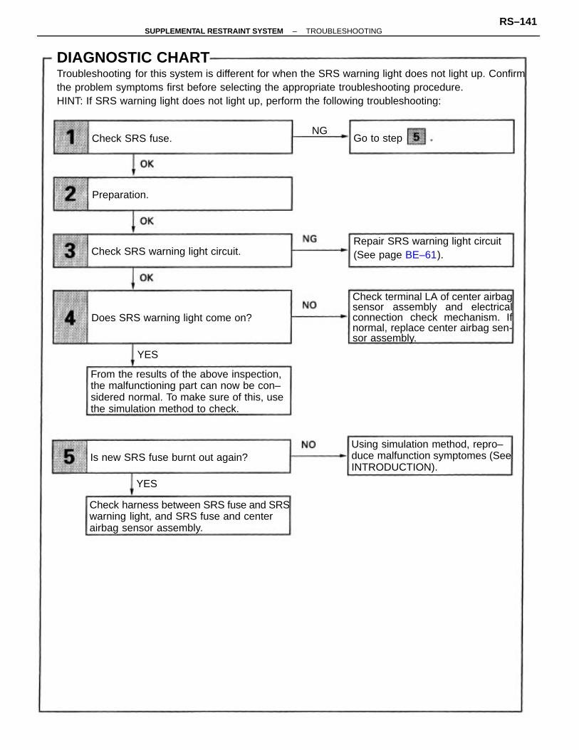
DIAGNOSTIC CHARTTroubleshooting for this system is different for when the SRS warning light does not light up. Confirmthe problem symptoms first before selecting the appropriate troubleshooting procedure.HINT: If SRS warning light does not light up, perform the following troubleshooting:
From the results of the above inspection,the malfunctioning part can now be con–sidered normal. To make sure of this, usethe simulation method to check.
Check terminal LA of center airbagsensor assembly and electricalconnection check mechanism. Ifnormal, replace center airbag sen-sor assembly.
Check harness between SRS fuse and SRSwarning light, and SRS fuse and centerairbag sensor assembly.
Using simulation method, repro–duce malfunction symptomes (SeeINTRODUCTION).
Repair SRS warning light circuit(See page BE–61).
Does SRS warning light come on?
Is new SRS fuse burnt out again?
Check SRS warning light circuit.
Check SRS fuse.
Preparation.
Go to step
YES
YES
NG
–SUPPLEMENTAL RESTRAINT SYSTEM TROUBLESHOOTINGRS–141
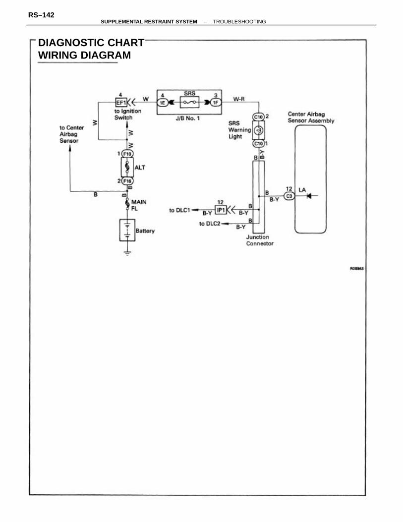
DIAGNOSTIC CHARTWIRING DIAGRAM
–SUPPLEMENTAL RESTRAINT SYSTEM TROUBLESHOOTINGRS–142

Disconnect battery negative H terminal cable,and wait at least 90 seconds.
(2) Remove steering wheel pad (See pageRS–20).(3) Disconnect connectors of front passengerairbag assembly. (See page RS–29).
INSPECTION PROCEDUREHINT: If SRS warning light does not light up, perform the following troubleshooting:
Check SRS fuse.
Preparation.
Go to step
Check Preparation
Store the steering wheel pad with the frontsurface facing upward.
–SUPPLEMENTAL RESTRAINT SYSTEM TROUBLESHOOTINGRS–143
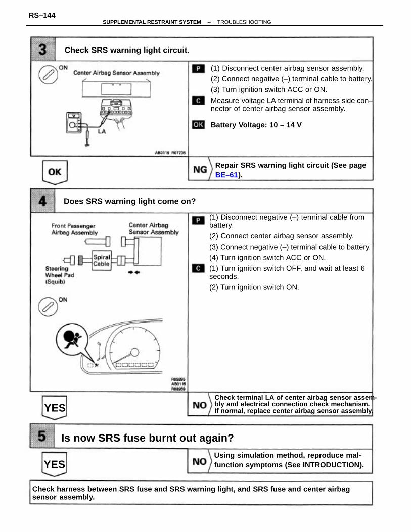
(1) Disconnect negative (–) terminal cable frombattery.
(2) Connect center airbag sensor assembly.
(3) Connect negative (–) terminal cable to battery.(4) Turn ignition switch ACC or ON.
(1) Turn ignition switch OFF, and wait at least 6seconds.
(2) Turn ignition switch ON.
(1) Disconnect center airbag sensor assembly.(2) Connect negative (–) terminal cable to battery.
(3) Turn ignition switch ACC or ON.
Measure voltage LA terminal of harness side con–nector of center airbag sensor assembly.
Battery Voltage: 10 – 14 V
Check harness between SRS fuse and SRS warning light, and SRS fuse and center airbag sensor assembly.
Check terminal LA of center airbag sensor assem-bly and electrical connection check mechanism. If normal, replace center airbag sensor assembly.
Using simulation method, reproduce mal-function symptoms (See INTRODUCTION).
Repair SRS warning light circuit (See pageBE–61).
Does SRS warning light come on?
Is now SRS fuse burnt out again?
Check SRS warning light circuit.
YES
YES
–SUPPLEMENTAL RESTRAINT SYSTEM TROUBLESHOOTINGRS–144

– MEMO –
–SUPPLEMENTAL RESTRAINT SYSTEM TROUBLESHOOTINGRS–145

CIRCUIT DESCRIPTIONThe SRS warning light is located on the combination meter.When the supplemental restraint system is normal, the SRS warning light lights up for approx. 6seconds after the ignition switch is turned from LOCK position to ACC or ON position, and then turnsoff automatically.If there is a malfunction in the supplemental restraint system, the SRS warning light lights up to in-form the driver of the abnormality.When terminals Tc and El of the DLC1 or DLC2 are connected, the diagnostic trouble code is dis-played by the blinking of the SRS warning light.
DIAGNOSTIC CHARTHINT: If the SRS warning light is always lit up by a DTC check procedure, perform Tc terminal circuitcheck procedure (See page RS–148).
SRS Warning Light System(Always Lit Up when ignition switch is LOCK position)
Check SRS warning light circuit orterminal AB circuit of DLC1 orDLC2.
Replace center airbag sensor assembly.
Does SRS warning light turn off?
WIRING DIAGRAM
YES
–SUPPLEMENTAL RESTRAINT SYSTEM TROUBLESHOOTINGRS–146

Turn ignition switch LOCK.(2) Disconnect negative H terminal cable frombattery and wait at least 90 seconds.
(3) Remove steering wheel pad (See page RS–20).
(4) Disconnect connectors of front passengerairbag assembly. (See page RS–29)
(5) Disconnect center airbag sensor assemblyconnector.
(6) Connect negative H terminal cable to battery.Check operation of SRS warning light.Ignition Switch is LOCK position.
Check SRS warning light circuit or terminalAB circuit DLC1 or DLC2.
Does SRS warning light turn off?
INSPECTION PROCEDURE
Replace center airbag sensor assembly.
Preparation
YES
Check
–SUPPLEMENTAL RESTRAINT SYSTEM TROUBLESHOOTINGRS–147

CIRCUIT DESCRIPTIONBy connecting terminals Tc and El of the DLC1 or DLC2, the center airbag sensor assembly is set inthe diagnostic trouble code output mode. The diagnostic trouble codes are displayed by the blinkingof theSRS warning light.
HINT: If the diagnostic trouble code is continuously displayed without a DTC check procedure, per–form the following troubleshooting:
Check harness between centerairbag sensor assembly and DLC1or DLC2.
Check resistance between terminal Tc ofcenter airbag sensor assembly and bodyground.
Check voltage between terminal Tc of DLC1or DLC2 and body ground.
Check voltage between terminals Tc and E,of DLC1 or DLC2.
Replace center airbag sensor as–sembly.
Check harness between terminalE1 of DLC1 or DLC2 and bodyground.
Replace center airbag sensor assembly.
Repair or replace harness or connector.
Check center airbag sensor assembly.
Tc Terminal Circuit
G o to step
DIAGNOSTIC CHARTTroubleshooting for this system is different depending on whether the diagnostic trouble code is notdisplayed SRS warning light is always lit up with a DTC check procedure, or is displayed without aDTC check procedure. Confirm the problem symptoms first before selecting the appropriate trou-bleshooting procedure.HINT: If the diagnostic trouble code is not displayed or SRS warning light is always lit up with aDTC check procedure perform the following troubleshooting:
OK
–SUPPLEMENTAL RESTRAINT SYSTEM TROUBLESHOOTINGRS–148

WIRING DIAGRAM
DIAGNOSTIC CHART
–SUPPLEMENTAL RESTRAINT SYSTEM TROUBLESHOOTINGRS–149

INSPECTION PROCEDUREHINT: If the diagnostic trouble code is not displayed, perform the following troubleshooting:
Turn ignition switch ACC or ON.Measure voltage between terminals Tc and El ofDLC1 or DLC2.
Battery Voltage: 10 – 14 V
Measure voltage between terminal Tc of DLC1 orDLC2 and body ground.Battery Voltage: 10 – 14 V
Check voltage between terminal Te of DLC1 or DLC2 and body ground.
Check voltage between terminals Te and El of DLC1 or DLC2.
Check harness between terminal El of DLC1or DLC2 and body ground.
Go to step 3
CheckPreparation
–SUPPLEMENTAL RESTRAINT SYSTEM TROUBLESHOOTINGRS–150

(1) Turn ignition switch LOCK.(2) Disconnect battery negative (–) terminal cable,and wait at least 90 seconds.
(3) Remove steering wheel pad (See page RS–20).
(4) Disconnect connectors of front passengerairbag assembly. (See page RS–29).Check operation of SRS warning light.
SRS warning light comes on.
Check harness between center airbag sensorassembly and DLC1 or DLC2.
Check center airbag sensor assembly.
Replace center airbag sensor assembly.
–SUPPLEMENTAL RESTRAINT SYSTEM TROUBLESHOOTINGRS–151

Turn ignition switch LOCK.(2) Disconnect center airbag sensor assemblyconnector.
(3) Disconnect battery negative (–) terminal cable,and wait at least 90 seconds.
(4) Remove steering wheel pad (See page RS–20).
(5) Disconnect connectors of front passengerairbag assembly. (See page RS–29).Check resistance between terminal Tc of centerairbag sensor assembly and body ground.
Resistance: 1 M or higher
HINT: If the diagnostic trouble code is continuously displayed, perform the following troubleshooting.
Check resistance between terminal Tc of center airbag sensor assemblyand body ground.
Replace center airbag sensor assembly.
Repair or replace harness or connector.
–SUPPLEMENTAL RESTRAINT SYSTEM TROUBLESHOOTINGRS–152

Front passenger airbag assembly to instrument panel reinforcement to instrument panel
SERVICE SPECIFICATIONSSERVICE DATA
TORQUE SPECIFICATIONS
Seat belt shoulder anchor bolt
Center airbag sensor
Front airbag sensor
Steering wheel pad
Front seat outer belt
Steering Wheel
Part tightened
–SUPPLEMENTAL RESTRAINT SYSTEM SERVICE SPECIFICATIONSRS–153


