Embed Size (px)
Citation preview

R&S®SMF100AMicrowave Signal GeneratorQuick Start Guide
Quick
Star
t Guid
e
1167.2302.62 ─ 11(;ÑG2Ì)
Test
& Me
asur
emen
t

This document describes the R&S®SMF100A, stock no. 1167.0000.02 and its options.
© 2016 Rohde & Schwarz GmbH & Co. KGMühldorfstr. 15, 81671 München, GermanyPhone: +49 89 41 29 - 0Fax: +49 89 41 29 12 164Email: [email protected]: www.rohde-schwarz.comSubject to change – Data without tolerance limits is not binding.R&S® is a registered trademark of Rohde & Schwarz GmbH & Co. KG.Trade names are trademarks of the owners.
The following abbreviations are used throughout this manual: R&S®SMF100A is abbreviated as R&S SMF, Linux® is abbreviated asLinux.

1171.0000.42 - 08 Page 1
Basic Safety Instructions
Always read through and comply with the following safety instructions!
All plants and locations of the Rohde & Schwarz group of companies make every effort to keep the safety
standards of our products up to date and to offer our customers the highest possible degree of safety. Our
products and the auxiliary equipment they require are designed, built and tested in accordance with the
safety standards that apply in each case. Compliance with these standards is continuously monitored by
our quality assurance system. The product described here has been designed, built and tested in
accordance with the EC Certificate of Conformity and has left the manufacturer’s plant in a condition fully
complying with safety standards. To maintain this condition and to ensure safe operation, you must
observe all instructions and warnings provided in this manual. If you have any questions regarding these
safety instructions, the Rohde & Schwarz group of companies will be happy to answer them.
Furthermore, it is your responsibility to use the product in an appropriate manner. This product is designed
for use solely in industrial and laboratory environments or, if expressly permitted, also in the field and must
not be used in any way that may cause personal injury or property damage. You are responsible if the
product is used for any purpose other than its designated purpose or in disregard of the manufacturer's
instructions. The manufacturer shall assume no responsibility for such use of the product.
The product is used for its designated purpose if it is used in accordance with its product documentation
and within its performance limits (see data sheet, documentation, the following safety instructions). Using
the product requires technical skills and, in some cases, a basic knowledge of English. It is therefore
essential that only skilled and specialized staff or thoroughly trained personnel with the required skills be
allowed to use the product. If personal safety gear is required for using Rohde & Schwarz products, this
will be indicated at the appropriate place in the product documentation. Keep the basic safety instructions
and the product documentation in a safe place and pass them on to the subsequent users.
Observing the safety instructions will help prevent personal injury or damage of any kind caused by
dangerous situations. Therefore, carefully read through and adhere to the following safety instructions
before and when using the product. It is also absolutely essential to observe the additional safety
instructions on personal safety, for example, that appear in relevant parts of the product documentation. In
these safety instructions, the word "product" refers to all merchandise sold and distributed by the Rohde &
Schwarz group of companies, including instruments, systems and all accessories. For product-specific
information, see the data sheet and the product documentation.
Safety labels on products
The following safety labels are used on products to warn against risks and dangers.
Symbol Meaning Symbol Meaning
Notice, general danger location
Observe product documentation
ON/OFF Power
Caution when handling heavy equipment
Standby indication
Danger of electric shock Direct current (DC)

Basic Safety Instructions
1171.0000.42 - 08 Page 2
Symbol Meaning Symbol Meaning
Caution ! Hot surface Alternating current (AC)
Protective conductor terminal
To identify any terminal which is intended for
connection to an external conductor for
protection against electric shock in case of a
fault, or the terminal of a protective earth
Direct/alternating current (DC/AC)
Earth (Ground)
Class II Equipment
to identify equipment meeting the safety
requirements specified for Class II equipment
(device protected by double or reinforced
insulation)
Frame or chassis Ground terminal
EU labeling for batteries and accumulators
For additional information, see section "Waste
disposal/Environmental protection", item 1.
Be careful when handling electrostatic sensitive
devices
EU labeling for separate collection of electrical
and electronic devices
For additional information, see section "Waste
disposal/Environmental protection", item 2.
Warning! Laser radiation
For additional information, see section
"Operation", item 7.
Signal words and their meaning
The following signal words are used in the product documentation in order to warn the reader about risks
and dangers.
Indicates a hazardous situation which, if not avoided, will result in death or
serious injury.
Indicates a hazardous situation which, if not avoided, could result in death or
serious injury.
Indicates a hazardous situation which, if not avoided, could result in minor or
moderate injury.
Indicates information considered important, but not hazard-related, e.g.
messages relating to property damage.
In the product documentation, the word ATTENTION is used synonymously.
These signal words are in accordance with the standard definition for civil applications in the European
Economic Area. Definitions that deviate from the standard definition may also exist in other economic
areas or military applications. It is therefore essential to make sure that the signal words described here
are always used only in connection with the related product documentation and the related product. The
use of signal words in connection with unrelated products or documentation can result in misinterpretation
and in personal injury or material damage.

Basic Safety Instructions
1171.0000.42 - 08 Page 3
Operating states and operating positions
The product may be operated only under the operating conditions and in the positions specified by the
manufacturer, without the product's ventilation being obstructed. If the manufacturer's specifications are
not observed, this can result in electric shock, fire and/or serious personal injury or death. Applicable local
or national safety regulations and rules for the prevention of accidents must be observed in all work
performed.
1. Unless otherwise specified, the following requirements apply to Rohde & Schwarz products:
predefined operating position is always with the housing floor facing down, IP protection 2X, use only
indoors, max. operating altitude 2000 m above sea level, max. transport altitude 4500 m above sea
level. A tolerance of ±10 % shall apply to the nominal voltage and ±5 % to the nominal frequency,
overvoltage category 2, pollution degree 2.
2. Do not place the product on surfaces, vehicles, cabinets or tables that for reasons of weight or stability
are unsuitable for this purpose. Always follow the manufacturer's installation instructions when
installing the product and fastening it to objects or structures (e.g. walls and shelves). An installation
that is not carried out as described in the product documentation could result in personal injury or
even death.
3. Do not place the product on heat-generating devices such as radiators or fan heaters. The ambient
temperature must not exceed the maximum temperature specified in the product documentation or in
the data sheet. Product overheating can cause electric shock, fire and/or serious personal injury or
even death.
Electrical safety
If the information on electrical safety is not observed either at all or to the extent necessary, electric shock,
fire and/or serious personal injury or death may occur.
1. Prior to switching on the product, always ensure that the nominal voltage setting on the product
matches the nominal voltage of the mains-supply network. If a different voltage is to be set, the power
fuse of the product may have to be changed accordingly.
2. In the case of products of safety class I with movable power cord and connector, operation is
permitted only on sockets with a protective conductor contact and protective conductor.
3. Intentionally breaking the protective conductor either in the feed line or in the product itself is not
permitted. Doing so can result in the danger of an electric shock from the product. If extension cords
or connector strips are implemented, they must be checked on a regular basis to ensure that they are
safe to use.
4. If there is no power switch for disconnecting the product from the mains, or if the power switch is not
suitable for this purpose, use the plug of the connecting cable to disconnect the product from the
mains. In such cases, always ensure that the power plug is easily reachable and accessible at all
times. For example, if the power plug is the disconnecting device, the length of the connecting cable
must not exceed 3 m. Functional or electronic switches are not suitable for providing disconnection
from the AC supply network. If products without power switches are integrated into racks or systems,
the disconnecting device must be provided at the system level.
5. Never use the product if the power cable is damaged. Check the power cables on a regular basis to
ensure that they are in proper operating condition. By taking appropriate safety measures and
carefully laying the power cable, ensure that the cable cannot be damaged and that no one can be
hurt by, for example, tripping over the cable or suffering an electric shock.

Basic Safety Instructions
1171.0000.42 - 08 Page 4
6. The product may be operated only from TN/TT supply networks fuse-protected with max. 16 A (higher
fuse only after consulting with the Rohde & Schwarz group of companies).
7. Do not insert the plug into sockets that are dusty or dirty. Insert the plug firmly and all the way into the
socket provided for this purpose. Otherwise, sparks that result in fire and/or injuries may occur.
8. Do not overload any sockets, extension cords or connector strips; doing so can cause fire or electric
shocks.
9. For measurements in circuits with voltages Vrms > 30 V, suitable measures (e.g. appropriate
measuring equipment, fuse protection, current limiting, electrical separation, insulation) should be
taken to avoid any hazards.
10. Ensure that the connections with information technology equipment, e.g. PCs or other industrial
computers, comply with the IEC 60950-1 / EN 60950-1 or IEC 61010-1 / EN 61010-1 standards that
apply in each case.
11. Unless expressly permitted, never remove the cover or any part of the housing while the product is in
operation. Doing so will expose circuits and components and can lead to injuries, fire or damage to the
product.
12. If a product is to be permanently installed, the connection between the protective conductor terminal
on site and the product's protective conductor must be made first before any other connection is
made. The product may be installed and connected only by a licensed electrician.
13. For permanently installed equipment without built-in fuses, circuit breakers or similar protective
devices, the supply circuit must be fuse-protected in such a way that anyone who has access to the
product, as well as the product itself, is adequately protected from injury or damage.
14. Use suitable overvoltage protection to ensure that no overvoltage (such as that caused by a bolt of
lightning) can reach the product. Otherwise, the person operating the product will be exposed to the
danger of an electric shock.
15. Any object that is not designed to be placed in the openings of the housing must not be used for this
purpose. Doing so can cause short circuits inside the product and/or electric shocks, fire or injuries.
16. Unless specified otherwise, products are not liquid-proof (see also section "Operating states and
operating positions", item 1). Therefore, the equipment must be protected against penetration by
liquids. If the necessary precautions are not taken, the user may suffer electric shock or the product
itself may be damaged, which can also lead to personal injury.
17. Never use the product under conditions in which condensation has formed or can form in or on the
product, e.g. if the product has been moved from a cold to a warm environment. Penetration by water
increases the risk of electric shock.
18. Prior to cleaning the product, disconnect it completely from the power supply (e.g. AC supply network
or battery). Use a soft, non-linting cloth to clean the product. Never use chemical cleaning agents such
as alcohol, acetone or diluents for cellulose lacquers.
Operation
1. Operating the products requires special training and intense concentration. Make sure that persons
who use the products are physically, mentally and emotionally fit enough to do so; otherwise, injuries
or material damage may occur. It is the responsibility of the employer/operator to select suitable
personnel for operating the products.

Basic Safety Instructions
1171.0000.42 - 08 Page 5
2. Before you move or transport the product, read and observe the section titled "Transport".
3. As with all industrially manufactured goods, the use of substances that induce an allergic reaction
(allergens) such as nickel cannot be generally excluded. If you develop an allergic reaction (such as a
skin rash, frequent sneezing, red eyes or respiratory difficulties) when using a Rohde & Schwarz
product, consult a physician immediately to determine the cause and to prevent health problems or
stress.
4. Before you start processing the product mechanically and/or thermally, or before you take it apart, be
sure to read and pay special attention to the section titled "Waste disposal/Environmental protection",
item 1.
5. Depending on the function, certain products such as RF radio equipment can produce an elevated
level of electromagnetic radiation. Considering that unborn babies require increased protection,
pregnant women must be protected by appropriate measures. Persons with pacemakers may also be
exposed to risks from electromagnetic radiation. The employer/operator must evaluate workplaces
where there is a special risk of exposure to radiation and, if necessary, take measures to avert the
potential danger.
6. Should a fire occur, the product may release hazardous substances (gases, fluids, etc.) that can
cause health problems. Therefore, suitable measures must be taken, e.g. protective masks and
protective clothing must be worn.
7. Laser products are given warning labels that are standardized according to their laser class. Lasers
can cause biological harm due to the properties of their radiation and due to their extremely
concentrated electromagnetic power. If a laser product (e.g. a CD/DVD drive) is integrated into a
Rohde & Schwarz product, absolutely no other settings or functions may be used as described in the
product documentation. The objective is to prevent personal injury (e.g. due to laser beams).
8. EMC classes (in line with EN 55011/CISPR 11, and analogously with EN 55022/CISPR 22,
EN 55032/CISPR 32)
Class A equipment:
Equipment suitable for use in all environments except residential environments and environments
that are directly connected to a low-voltage supply network that supplies residential buildings
Note: Class A equipment is intended for use in an industrial environment. This equipment may
cause radio disturbances in residential environments, due to possible conducted as well as
radiated disturbances. In this case, the operator may be required to take appropriate measures to
eliminate these disturbances.
Class B equipment:
Equipment suitable for use in residential environments and environments that are directly
connected to a low-voltage supply network that supplies residential buildings
Repair and service
1. The product may be opened only by authorized, specially trained personnel. Before any work is
performed on the product or before the product is opened, it must be disconnected from the AC supply
network. Otherwise, personnel will be exposed to the risk of an electric shock.

Basic Safety Instructions
1171.0000.42 - 08 Page 6
2. Adjustments, replacement of parts, maintenance and repair may be performed only by electrical
experts authorized by Rohde & Schwarz. Only original parts may be used for replacing parts relevant
to safety (e.g. power switches, power transformers, fuses). A safety test must always be performed
after parts relevant to safety have been replaced (visual inspection, protective conductor test,
insulation resistance measurement, leakage current measurement, functional test). This helps ensure
the continued safety of the product.
Batteries and rechargeable batteries/cells
If the information regarding batteries and rechargeable batteries/cells is not observed either at all or to the
extent necessary, product users may be exposed to the risk of explosions, fire and/or serious personal
injury, and, in some cases, death. Batteries and rechargeable batteries with alkaline electrolytes (e.g.
lithium cells) must be handled in accordance with the EN 62133 standard.
1. Cells must not be taken apart or crushed.
2. Cells or batteries must not be exposed to heat or fire. Storage in direct sunlight must be avoided.
Keep cells and batteries clean and dry. Clean soiled connectors using a dry, clean cloth.
3. Cells or batteries must not be short-circuited. Cells or batteries must not be stored in a box or in a
drawer where they can short-circuit each other, or where they can be short-circuited by other
conductive materials. Cells and batteries must not be removed from their original packaging until they
are ready to be used.
4. Cells and batteries must not be exposed to any mechanical shocks that are stronger than permitted.
5. If a cell develops a leak, the fluid must not be allowed to come into contact with the skin or eyes. If
contact occurs, wash the affected area with plenty of water and seek medical aid.
6. Improperly replacing or charging cells or batteries that contain alkaline electrolytes (e.g. lithium cells)
can cause explosions. Replace cells or batteries only with the matching Rohde & Schwarz type (see
parts list) in order to ensure the safety of the product.
7. Cells and batteries must be recycled and kept separate from residual waste. Rechargeable batteries
and normal batteries that contain lead, mercury or cadmium are hazardous waste. Observe the
national regulations regarding waste disposal and recycling.
Transport
1. The product may be very heavy. Therefore, the product must be handled with care. In some cases,
the user may require a suitable means of lifting or moving the product (e.g. with a lift-truck) to avoid
back or other physical injuries.
2. Handles on the products are designed exclusively to enable personnel to transport the product. It is
therefore not permissible to use handles to fasten the product to or on transport equipment such as
cranes, fork lifts, wagons, etc. The user is responsible for securely fastening the products to or on the
means of transport or lifting. Observe the safety regulations of the manufacturer of the means of
transport or lifting. Noncompliance can result in personal injury or material damage.
3. If you use the product in a vehicle, it is the sole responsibility of the driver to drive the vehicle safely
and properly. The manufacturer assumes no responsibility for accidents or collisions. Never use the
product in a moving vehicle if doing so could distract the driver of the vehicle. Adequately secure the
product in the vehicle to prevent injuries or other damage in the event of an accident.

Instrucciones de seguridad elementales
1171.0000.42 - 08 Page 7
Waste disposal/Environmental protection
1. Specially marked equipment has a battery or accumulator that must not be disposed of with unsorted
municipal waste, but must be collected separately. It may only be disposed of at a suitable collection
point or via a Rohde & Schwarz customer service center.
2. Waste electrical and electronic equipment must not be disposed of with unsorted municipal waste, but
must be collected separately.
Rohde & Schwarz GmbH & Co. KG has developed a disposal concept and takes full responsibility for
take-back obligations and disposal obligations for manufacturers within the EU. Contact your
Rohde & Schwarz customer service center for environmentally responsible disposal of the product.
3. If products or their components are mechanically and/or thermally processed in a manner that goes
beyond their intended use, hazardous substances (heavy-metal dust such as lead, beryllium, nickel)
may be released. For this reason, the product may only be disassembled by specially trained
personnel. Improper disassembly may be hazardous to your health. National waste disposal
regulations must be observed.
4. If handling the product releases hazardous substances or fuels that must be disposed of in a special
way, e.g. coolants or engine oils that must be replenished regularly, the safety instructions of the
manufacturer of the hazardous substances or fuels and the applicable regional waste disposal
regulations must be observed. Also observe the relevant safety instructions in the product
documentation. The improper disposal of hazardous substances or fuels can cause health problems
and lead to environmental damage.
For additional information about environmental protection, visit the Rohde & Schwarz website.
Instrucciones de seguridad elementales
¡Es imprescindible leer y cumplir las siguientes instrucciones e informaciones de seguridad!
El principio del grupo de empresas Rohde & Schwarz consiste en tener nuestros productos siempre al día
con los estándares de seguridad y de ofrecer a nuestros clientes el máximo grado de seguridad. Nuestros
productos y todos los equipos adicionales son siempre fabricados y examinados según las normas de
seguridad vigentes. Nuestro sistema de garantía de calidad controla constantemente que sean cumplidas
estas normas. El presente producto ha sido fabricado y examinado según el certificado de conformidad
de la UE y ha salido de nuestra planta en estado impecable según los estándares técnicos de seguridad.
Para poder preservar este estado y garantizar un funcionamiento libre de peligros, el usuario deberá
atenerse a todas las indicaciones, informaciones de seguridad y notas de alerta. El grupo de empresas
Rohde & Schwarz está siempre a su disposición en caso de que tengan preguntas referentes a estas
informaciones de seguridad.
Además queda en la responsabilidad del usuario utilizar el producto en la forma debida. Este producto
está destinado exclusivamente al uso en la industria y el laboratorio o, si ha sido expresamente
autorizado, para aplicaciones de campo y de ninguna manera deberá ser utilizado de modo que alguna
persona/cosa pueda sufrir daño. El uso del producto fuera de sus fines definidos o sin tener en cuenta las
instrucciones del fabricante queda en la responsabilidad del usuario. El fabricante no se hace en ninguna
forma responsable de consecuencias a causa del mal uso del producto.

Instrucciones de seguridad elementales
1171.0000.42 - 08 Page 8
Se parte del uso correcto del producto para los fines definidos si el producto es utilizado conforme a las
indicaciones de la correspondiente documentación del producto y dentro del margen de rendimiento
definido (ver hoja de datos, documentación, informaciones de seguridad que siguen). El uso del producto
hace necesarios conocimientos técnicos y ciertos conocimientos del idioma inglés. Por eso se debe tener
en cuenta que el producto solo pueda ser operado por personal especializado o personas instruidas en
profundidad con las capacidades correspondientes. Si fuera necesaria indumentaria de seguridad para el
uso de productos de Rohde & Schwarz, encontraría la información debida en la documentación del
producto en el capítulo correspondiente. Guarde bien las informaciones de seguridad elementales, así
como la documentación del producto, y entréguelas a usuarios posteriores.
Tener en cuenta las informaciones de seguridad sirve para evitar en lo posible lesiones o daños por
peligros de toda clase. Por eso es imprescindible leer detalladamente y comprender por completo las
siguientes informaciones de seguridad antes de usar el producto, y respetarlas durante el uso del
producto. Deberán tenerse en cuenta todas las demás informaciones de seguridad, como p. ej. las
referentes a la protección de personas, que encontrarán en el capítulo correspondiente de la
documentación del producto y que también son de obligado cumplimiento. En las presentes
informaciones de seguridad se recogen todos los objetos que distribuye el grupo de empresas
Rohde & Schwarz bajo la denominación de "producto", entre ellos también aparatos, instalaciones así
como toda clase de accesorios. Los datos específicos del producto figuran en la hoja de datos y en la
documentación del producto.
Señalización de seguridad de los productos
Las siguientes señales de seguridad se utilizan en los productos para advertir sobre riesgos y peligros.
Símbolo Significado Símbolo Significado
Aviso: punto de peligro general
Observar la documentación del producto
Tensión de alimentación de PUESTA EN
MARCHA / PARADA
Atención en el manejo de dispositivos de peso
elevado
Indicación de estado de espera (standby)
Peligro de choque eléctrico Corriente continua (DC)
Advertencia: superficie caliente Corriente alterna (AC)
Conexión a conductor de protección Corriente continua / Corriente alterna (DC/AC)
Conexión a tierra
El aparato está protegido en su totalidad por un
aislamiento doble (reforzado)
Conexión a masa
Distintivo de la UE para baterías y
acumuladores
Más información en la sección
"Eliminación/protección del medio ambiente",
punto 1.

Instrucciones de seguridad elementales
1171.0000.42 - 08 Page 9
Símbolo Significado Símbolo Significado
Aviso: Cuidado en el manejo de dispositivos
sensibles a la electrostática (ESD)
Distintivo de la UE para la eliminación por
separado de dispositivos eléctricos y
electrónicos
Más información en la sección
"Eliminación/protección del medio ambiente",
punto 2.
Advertencia: rayo láser
Más información en la sección
"Funcionamiento", punto 7.
Palabras de señal y su significado
En la documentación del producto se utilizan las siguientes palabras de señal con el fin de advertir contra
riesgos y peligros.
Indica una situación de peligro que, si no se evita, causa lesiones
graves o incluso la muerte.
Indica una situación de peligro que, si no se evita, puede causar
lesiones graves o incluso la muerte.
Indica una situación de peligro que, si no se evita, puede causar
lesiones leves o moderadas.
Indica información que se considera importante, pero no en relación
con situaciones de peligro; p. ej., avisos sobre posibles daños
materiales.
En la documentación del producto se emplea de forma sinónima el
término CUIDADO.
Las palabras de señal corresponden a la definición habitual para aplicaciones civiles en el área
económica europea. Pueden existir definiciones diferentes a esta definición en otras áreas económicas o
en aplicaciones militares. Por eso se deberá tener en cuenta que las palabras de señal aquí descritas
sean utilizadas siempre solamente en combinación con la correspondiente documentación del producto y
solamente en combinación con el producto correspondiente. La utilización de las palabras de señal en
combinación con productos o documentaciones que no les correspondan puede llevar a interpretaciones
equivocadas y tener por consecuencia daños en personas u objetos.
Estados operativos y posiciones de funcionamiento
El producto solamente debe ser utilizado según lo indicado por el fabricante respecto a los estados
operativos y posiciones de funcionamiento sin que se obstruya la ventilación. Si no se siguen las
indicaciones del fabricante, pueden producirse choques eléctricos, incendios y/o lesiones graves con
posible consecuencia de muerte. En todos los trabajos deberán ser tenidas en cuenta las normas
nacionales y locales de seguridad del trabajo y de prevención de accidentes.

Instrucciones de seguridad elementales
1171.0000.42 - 08 Page 10
1. Si no se convino de otra manera, es para los productos Rohde & Schwarz válido lo que sigue:
como posición de funcionamiento se define por principio la posición con el suelo de la caja para
abajo, modo de protección IP 2X, uso solamente en estancias interiores, utilización hasta 2000 m
sobre el nivel del mar, transporte hasta 4500 m sobre el nivel del mar. Se aplicará una tolerancia de
±10 % sobre el voltaje nominal y de ±5 % sobre la frecuencia nominal. Categoría de sobrecarga
eléctrica 2, índice de suciedad 2.
2. No sitúe el producto encima de superficies, vehículos, estantes o mesas, que por sus características
de peso o de estabilidad no sean aptos para él. Siga siempre las instrucciones de instalación del
fabricante cuando instale y asegure el producto en objetos o estructuras (p. ej. paredes y estantes). Si
se realiza la instalación de modo distinto al indicado en la documentación del producto, se pueden
causar lesiones o, en determinadas circunstancias, incluso la muerte.
3. No ponga el producto sobre aparatos que generen calor (p. ej. radiadores o calefactores). La
temperatura ambiente no debe superar la temperatura máxima especificada en la documentación del
producto o en la hoja de datos. En caso de sobrecalentamiento del producto, pueden producirse
choques eléctricos, incendios y/o lesiones graves con posible consecuencia de muerte.
Seguridad eléctrica
Si no se siguen (o se siguen de modo insuficiente) las indicaciones del fabricante en cuanto a seguridad
eléctrica, pueden producirse choques eléctricos, incendios y/o lesiones graves con posible consecuencia
de muerte.
1. Antes de la puesta en marcha del producto se deberá comprobar siempre que la tensión
preseleccionada en el producto coincida con la de la red de alimentación eléctrica. Si es necesario
modificar el ajuste de tensión, también se deberán cambiar en caso dado los fusibles
correspondientes del producto.
2. Los productos de la clase de protección I con alimentación móvil y enchufe individual solamente
podrán enchufarse a tomas de corriente con contacto de seguridad y con conductor de protección
conectado.
3. Queda prohibida la interrupción intencionada del conductor de protección, tanto en la toma de
corriente como en el mismo producto. La interrupción puede tener como consecuencia el riesgo de
que el producto sea fuente de choques eléctricos. Si se utilizan cables alargadores o regletas de
enchufe, deberá garantizarse la realización de un examen regular de los mismos en cuanto a su
estado técnico de seguridad.
4. Si el producto no está equipado con un interruptor para desconectarlo de la red, o bien si el
interruptor existente no resulta apropiado para la desconexión de la red, el enchufe del cable de
conexión se deberá considerar como un dispositivo de desconexión.
El dispositivo de desconexión se debe poder alcanzar fácilmente y debe estar siempre bien accesible.
Si, p. ej., el enchufe de conexión a la red es el dispositivo de desconexión, la longitud del cable de
conexión no debe superar 3 m).
Los interruptores selectores o electrónicos no son aptos para el corte de la red eléctrica. Si se
integran productos sin interruptor en bastidores o instalaciones, se deberá colocar el interruptor en el
nivel de la instalación.
5. No utilice nunca el producto si está dañado el cable de conexión a red. Compruebe regularmente el
correcto estado de los cables de conexión a red. Asegúrese, mediante las medidas de protección y
de instalación adecuadas, de que el cable de conexión a red no pueda ser dañado o de que nadie
pueda ser dañado por él, p. ej. al tropezar o por un choque eléctrico.
Instrucciones de seguridad elementales
1171.0000.42 - 08 Page 11
6. Solamente está permitido el funcionamiento en redes de alimentación TN/TT aseguradas con fusibles
de 16 A como máximo (utilización de fusibles de mayor amperaje solo previa consulta con el grupo de
empresas Rohde & Schwarz).
7. Nunca conecte el enchufe en tomas de corriente sucias o llenas de polvo. Introduzca el enchufe por
completo y fuertemente en la toma de corriente. La no observación de estas medidas puede provocar
chispas, fuego y/o lesiones.
8. No sobrecargue las tomas de corriente, los cables alargadores o las regletas de enchufe ya que esto
podría causar fuego o choques eléctricos.
9. En las mediciones en circuitos de corriente con una tensión Ueff > 30 V se deberán tomar las medidas
apropiadas para impedir cualquier peligro (p. ej. medios de medición adecuados, seguros, limitación
de tensión, corte protector, aislamiento etc.).
10. Para la conexión con dispositivos informáticos como un PC o un ordenador industrial, debe
comprobarse que éstos cumplan los estándares IEC60950-1/EN60950-1 o IEC61010-1/EN 61010-1
válidos en cada caso.
11. A menos que esté permitido expresamente, no retire nunca la tapa ni componentes de la carcasa
mientras el producto esté en servicio. Esto pone a descubierto los cables y componentes eléctricos y
puede causar lesiones, fuego o daños en el producto.
12. Si un producto se instala en un lugar fijo, se deberá primero conectar el conductor de protección fijo
con el conductor de protección del producto antes de hacer cualquier otra conexión. La instalación y
la conexión deberán ser efectuadas por un electricista especializado.
13. En el caso de dispositivos fijos que no estén provistos de fusibles, interruptor automático ni otros
mecanismos de seguridad similares, el circuito de alimentación debe estar protegido de modo que
todas las personas que puedan acceder al producto, así como el producto mismo, estén a salvo de
posibles daños.
14. Todo producto debe estar protegido contra sobretensión (debida p. ej. a una caída del rayo) mediante
los correspondientes sistemas de protección. Si no, el personal que lo utilice quedará expuesto al
peligro de choque eléctrico.
15. No debe introducirse en los orificios de la caja del aparato ningún objeto que no esté destinado a ello.
Esto puede producir cortocircuitos en el producto y/o puede causar choques eléctricos, fuego o
lesiones.
16. Salvo indicación contraria, los productos no están impermeabilizados (ver también el capítulo
"Estados operativos y posiciones de funcionamiento", punto 1). Por eso es necesario tomar las
medidas necesarias para evitar la entrada de líquidos. En caso contrario, existe peligro de choque
eléctrico para el usuario o de daños en el producto, que también pueden redundar en peligro para las
personas.
17. No utilice el producto en condiciones en las que pueda producirse o ya se hayan producido
condensaciones sobre el producto o en el interior de éste, como p. ej. al desplazarlo de un lugar frío a
otro caliente. La entrada de agua aumenta el riesgo de choque eléctrico.
18. Antes de la limpieza, desconecte por completo el producto de la alimentación de tensión (p. ej. red de
alimentación o batería). Realice la limpieza de los aparatos con un paño suave, que no se deshilache.
No utilice bajo ningún concepto productos de limpieza químicos como alcohol, acetona o diluyentes
para lacas nitrocelulósicas.

Instrucciones de seguridad elementales
1171.0000.42 - 08 Page 12
Funcionamiento
1. El uso del producto requiere instrucciones especiales y una alta concentración durante el manejo.
Debe asegurarse que las personas que manejen el producto estén a la altura de los requerimientos
necesarios en cuanto a aptitudes físicas, psíquicas y emocionales, ya que de otra manera no se
pueden excluir lesiones o daños de objetos. El empresario u operador es responsable de seleccionar
el personal usuario apto para el manejo del producto.
2. Antes de desplazar o transportar el producto, lea y tenga en cuenta el capítulo "Transporte".
3. Como con todo producto de fabricación industrial no puede quedar excluida en general la posibilidad
de que se produzcan alergias provocadas por algunos materiales empleados ―los llamados
alérgenos (p. ej. el níquel)―. Si durante el manejo de productos Rohde & Schwarz se producen
reacciones alérgicas, como p. ej. irritaciones cutáneas, estornudos continuos, enrojecimiento de la
conjuntiva o dificultades respiratorias, debe avisarse inmediatamente a un médico para investigar las
causas y evitar cualquier molestia o daño a la salud.
4. Antes de la manipulación mecánica y/o térmica o el desmontaje del producto, debe tenerse en cuenta
imprescindiblemente el capítulo "Eliminación/protección del medio ambiente", punto 1.
5. Ciertos productos, como p. ej. las instalaciones de radiocomunicación RF, pueden a causa de su
función natural, emitir una radiación electromagnética aumentada. Deben tomarse todas las medidas
necesarias para la protección de las mujeres embarazadas. También las personas con marcapasos
pueden correr peligro a causa de la radiación electromagnética. El empresario/operador tiene la
obligación de evaluar y señalizar las áreas de trabajo en las que exista un riesgo elevado de
exposición a radiaciones.
6. Tenga en cuenta que en caso de incendio pueden desprenderse del producto sustancias tóxicas
(gases, líquidos etc.) que pueden generar daños a la salud. Por eso, en caso de incendio deben
usarse medidas adecuadas, como p. ej. máscaras antigás e indumentaria de protección.
7. Los productos con láser están provistos de indicaciones de advertencia normalizadas en función de la
clase de láser del que se trate. Los rayos láser pueden provocar daños de tipo biológico a causa de
las propiedades de su radiación y debido a su concentración extrema de potencia electromagnética.
En caso de que un producto Rohde & Schwarz contenga un producto láser (p. ej. un lector de
CD/DVD), no debe usarse ninguna otra configuración o función aparte de las descritas en la
documentación del producto, a fin de evitar lesiones (p. ej. debidas a irradiación láser).
8. Clases de compatibilidad electromagnética (conforme a EN 55011 / CISPR 11; y en analogía con EN
55022 / CISPR 22, EN 55032 / CISPR 32)
Aparato de clase A:
Aparato adecuado para su uso en todos los entornos excepto en los residenciales y en aquellos
conectados directamente a una red de distribución de baja tensión que suministra corriente a
edificios residenciales.
Nota: Los aparatos de clase A están destinados al uso en entornos industriales. Estos aparatos
pueden causar perturbaciones radioeléctricas en entornos residenciales debido a posibles
perturbaciones guiadas o radiadas. En este caso, se le podrá solicitar al operador que tome las
medidas adecuadas para eliminar estas perturbaciones.
Aparato de clase B:
Aparato adecuado para su uso en entornos residenciales, así como en aquellos conectados
directamente a una red de distribución de baja tensión que suministra corriente a edificios
residenciales.

Instrucciones de seguridad elementales
1171.0000.42 - 08 Page 13
Reparación y mantenimiento
1. El producto solamente debe ser abierto por personal especializado con autorización para ello. Antes
de manipular el producto o abrirlo, es obligatorio desconectarlo de la tensión de alimentación, para
evitar toda posibilidad de choque eléctrico.
2. El ajuste, el cambio de partes, el mantenimiento y la reparación deberán ser efectuadas solamente
por electricistas autorizados por Rohde & Schwarz. Si se reponen partes con importancia para los
aspectos de seguridad (p. ej. el enchufe, los transformadores o los fusibles), solamente podrán ser
sustituidos por partes originales. Después de cada cambio de partes relevantes para la seguridad
deberá realizarse un control de seguridad (control a primera vista, control del conductor de
protección, medición de resistencia de aislamiento, medición de la corriente de fuga, control de
funcionamiento). Con esto queda garantizada la seguridad del producto.
Baterías y acumuladores o celdas
Si no se siguen (o se siguen de modo insuficiente) las indicaciones en cuanto a las baterías y
acumuladores o celdas, pueden producirse explosiones, incendios y/o lesiones graves con posible
consecuencia de muerte. El manejo de baterías y acumuladores con electrolitos alcalinos (p. ej. celdas de
litio) debe seguir el estándar EN 62133.
1. No deben desmontarse, abrirse ni triturarse las celdas.
2. Las celdas o baterías no deben someterse a calor ni fuego. Debe evitarse el almacenamiento a la luz
directa del sol. Las celdas y baterías deben mantenerse limpias y secas. Limpiar las conexiones
sucias con un paño seco y limpio.
3. Las celdas o baterías no deben cortocircuitarse. Es peligroso almacenar las celdas o baterías en
estuches o cajones en cuyo interior puedan cortocircuitarse por contacto recíproco o por contacto con
otros materiales conductores. No deben extraerse las celdas o baterías de sus embalajes originales
hasta el momento en que vayan a utilizarse.
4. Las celdas o baterías no deben someterse a impactos mecánicos fuertes indebidos.
5. En caso de falta de estanqueidad de una celda, el líquido vertido no debe entrar en contacto con la
piel ni los ojos. Si se produce contacto, lavar con agua abundante la zona afectada y avisar a un
médico.
6. En caso de cambio o recarga inadecuados, las celdas o baterías que contienen electrolitos alcalinos
(p. ej. las celdas de litio) pueden explotar. Para garantizar la seguridad del producto, las celdas o
baterías solo deben ser sustituidas por el tipo Rohde & Schwarz correspondiente (ver lista de
recambios).
7. Las baterías y celdas deben reciclarse y no deben tirarse a la basura doméstica. Las baterías o
acumuladores que contienen plomo, mercurio o cadmio deben tratarse como residuos especiales.
Respete en esta relación las normas nacionales de eliminación y reciclaje.
Transporte
1. El producto puede tener un peso elevado. Por eso es necesario desplazarlo o transportarlo con
precaución y, si es necesario, usando un sistema de elevación adecuado (p. ej. una carretilla
elevadora), a fin de evitar lesiones en la espalda u otros daños personales.

Instrucciones de seguridad elementales
1171.0000.42 - 08 Page 14
2. Las asas instaladas en los productos sirven solamente de ayuda para el transporte del producto por
personas. Por eso no está permitido utilizar las asas para la sujeción en o sobre medios de transporte
como p. ej. grúas, carretillas elevadoras de horquilla, carros etc. Es responsabilidad suya fijar los
productos de manera segura a los medios de transporte o elevación. Para evitar daños personales o
daños en el producto, siga las instrucciones de seguridad del fabricante del medio de transporte o
elevación utilizado.
3. Si se utiliza el producto dentro de un vehículo, recae de manera exclusiva en el conductor la
responsabilidad de conducir el vehículo de manera segura y adecuada. El fabricante no asumirá
ninguna responsabilidad por accidentes o colisiones. No utilice nunca el producto dentro de un
vehículo en movimiento si esto pudiera distraer al conductor. Asegure el producto dentro del vehículo
debidamente para evitar, en caso de un accidente, lesiones u otra clase de daños.
Eliminación/protección del medio ambiente
1. Los dispositivos marcados contienen una batería o un acumulador que no se debe desechar con los
residuos domésticos sin clasificar, sino que debe ser recogido por separado. La eliminación se debe
efectuar exclusivamente a través de un punto de recogida apropiado o del servicio de atención al
cliente de Rohde & Schwarz.
2. Los dispositivos eléctricos usados no se deben desechar con los residuos domésticos sin clasificar,
sino que deben ser recogidos por separado.
Rohde & Schwarz GmbH & Co.KG ha elaborado un concepto de eliminación de residuos y asume
plenamente los deberes de recogida y eliminación para los fabricantes dentro de la UE. Para
desechar el producto de manera respetuosa con el medio ambiente, diríjase a su servicio de atención
al cliente de Rohde & Schwarz.
3. Si se trabaja de manera mecánica y/o térmica cualquier producto o componente más allá del
funcionamiento previsto, pueden liberarse sustancias peligrosas (polvos con contenido de metales
pesados como p. ej. plomo, berilio o níquel). Por eso el producto solo debe ser desmontado por
personal especializado con formación adecuada. Un desmontaje inadecuado puede ocasionar daños
para la salud. Se deben tener en cuenta las directivas nacionales referentes a la eliminación de
residuos.
4. En caso de que durante el trato del producto se formen sustancias peligrosas o combustibles que
deban tratarse como residuos especiales (p. ej. refrigerantes o aceites de motor con intervalos de
cambio definidos), deben tenerse en cuenta las indicaciones de seguridad del fabricante de dichas
sustancias y las normas regionales de eliminación de residuos. Tenga en cuenta también en caso
necesario las indicaciones de seguridad especiales contenidas en la documentación del producto. La
eliminación incorrecta de sustancias peligrosas o combustibles puede causar daños a la salud o
daños al medio ambiente.
Se puede encontrar más información sobre la protección del medio ambiente en la página web de
Rohde & Schwarz.

1171.0200.22-06.00
Customer Support
Technical support – where and when you need it For quick, expert help with any Rohde & Schwarz equipment, contact one of our Customer Support Centers. A team of highly qualified engineers provides telephone support and will work with you to find a solution to your query on any aspect of the operation, programming or applications of Rohde & Schwarz equipment.
Up-to-date information and upgrades To keep your instrument up-to-date and to be informed about new application notes related to your instrument, please send an e-mail to the Customer Support Center stating your instrument and your wish. We will take care that you will get the right information.
Europe, Africa, Middle East Phone +49 89 4129 12345 [email protected]
North America Phone 1-888-TEST-RSA (1-888-837-8772) [email protected]
Latin America Phone +1-410-910-7988 [email protected]
Asia/Pacific Phone +65 65 13 04 88 [email protected]
China Phone +86-800-810-8228 / +86-400-650-5896 [email protected]

ContentsR&S®SMF100A
3Quick Start Guide 1167.2302.62 ─ 11
Contents1 Preface.................................................................................................... 7
1.1 Documentation Overview............................................................................................. 7
1.2 Typographical Conventions.........................................................................................8
1.3 Notes on Screenshots.................................................................................................. 8
2 Preparing for Use.................................................................................112.1 Front Panel Tour......................................................................................................... 11
2.1.1 Utility Keys.................................................................................................................... 12
2.1.2 Standby LEDs and Standby Key...................................................................................12
2.1.3 Display.......................................................................................................................... 13
2.1.4 Setup Keys....................................................................................................................13
2.1.4.1 Keys for Setting Parameters......................................................................................... 13
2.1.4.2 Display Keys................................................................................................................. 14
2.1.5 Keypad for data entry....................................................................................................15
2.1.6 Rotary Knob and Navigation Keys................................................................................ 16
2.1.7 Front Panel Connectors................................................................................................ 17
2.2 Rear Panel Tour...........................................................................................................19
2.2.1 Description of the Connectors.......................................................................................19
2.3 Putting into Operation................................................................................................ 23
2.3.1 EMI Suppression...........................................................................................................24
2.3.2 Unpacking and Checking the Instrument...................................................................... 24
2.3.3 Placing or Mounting the Instrument.............................................................................. 25
2.3.4 Connecting the Instrument to the AC Supply................................................................ 26
2.3.5 Starting the Instrument..................................................................................................27
2.3.5.1 Standby and Ready state..............................................................................................27
2.3.5.2 Start Display and Booting..............................................................................................27
2.3.5.3 Function Check............................................................................................................. 28
2.3.5.4 Default Settings.............................................................................................................28
2.3.6 Shutting Down the Instrument.......................................................................................29
2.3.7 Power Fuses................................................................................................................. 30
2.4 Connecting External Accessories............................................................................. 30
2.4.1 Connecting USB Devices..............................................................................................30

ContentsR&S®SMF100A
4Quick Start Guide 1167.2302.62 ─ 11
2.5 Linux Operating System.............................................................................................31
2.6 Setting Up a Network (LAN) Connection...................................................................33
2.6.1 Connecting the Instrument to the Network....................................................................33
2.6.2 Assigning the IP Address.............................................................................................. 34
2.6.3 Using Computer Names................................................................................................35
2.7 Remote Access via an External Controller...............................................................36
2.7.1 Using a Web Browser for Remote Access.................................................................... 37
2.7.2 Remote Access via a VNC Client Software.................................................................. 38
2.8 LXI Configuration........................................................................................................ 43
2.8.1 LXI Browser Settings.....................................................................................................44
2.8.2 LAN Configuration.........................................................................................................46
2.8.2.1 IP Configuration............................................................................................................ 46
2.8.2.2 Advanced LAN Configuration........................................................................................47
2.8.2.3 Ping Client.....................................................................................................................48
2.8.2.4 Web Control.................................................................................................................. 49
2.8.2.5 SCPI Remote Trace...................................................................................................... 51
3 Getting Started..................................................................................... 533.1 Brief Introduction to the Instrument's Concept....................................................... 53
3.2 Application Field of the Instrument...........................................................................55
3.3 Description of Individual Diagram Blocks................................................................ 56
3.4 Example of Setup........................................................................................................ 58
4 Manual Operation.................................................................................674.1 Key Features................................................................................................................67
4.2 Display......................................................................................................................... 71
4.2.1 Settings Displayed in the Header Section.....................................................................71
4.2.2 Status Information and Messages.................................................................................72
4.2.2.1 Status Information......................................................................................................... 72
4.2.2.2 Messages......................................................................................................................72
4.2.2.3 Volatile messages......................................................................................................... 72
4.2.2.4 Permanent Messages................................................................................................... 73
4.2.3 Info Window.................................................................................................................. 73
4.2.4 Block Diagram ..............................................................................................................74
4.2.4.1 Function Blocks in the Block Diagram...........................................................................74

ContentsR&S®SMF100A
5Quick Start Guide 1167.2302.62 ─ 11
4.2.4.2 Signal Flow and Input/Output Symbols in the Block Diagram.......................................75
4.2.5 Structure of the Dialogs.................................................................................................75
4.3 Accessing Dialogs...................................................................................................... 76
4.4 Setting Parameters..................................................................................................... 77
4.4.1 Working with the Cursor................................................................................................78
4.4.2 Selecting a Control Element..........................................................................................79
4.4.3 Switching Parameters On/Off........................................................................................79
4.4.4 Entering a Value............................................................................................................80
4.4.5 Working with Units ....................................................................................................... 81
4.4.6 Selecting a Value from a List........................................................................................ 82
4.4.7 Terminating Entries with Confirmation.......................................................................... 82
4.4.8 Restoring the Previous Value........................................................................................83
4.5 Editors..........................................................................................................................84
4.5.1 Working with List Editor.................................................................................................84
4.6 How to Use the Help System......................................................................................86
4.7 File Management......................................................................................................... 87
4.7.1 File Select Dialog.......................................................................................................... 89
4.7.2 File Manager................................................................................................................. 90
4.7.2.1 Extensions for User Files.............................................................................................. 91
4.8 Legend of Front-Panel Controls................................................................................ 91
4.8.1 Front Panel Key Emulation........................................................................................... 93
Annex.................................................................................................... 95
A Hardware Interfaces.............................................................................95A.1 GPIB Bus Interface......................................................................................................95
Index......................................................................................................97

ContentsR&S®SMF100A
6Quick Start Guide 1167.2302.62 ─ 11

PrefaceR&S®SMF100A
7Quick Start Guide 1167.2302.62 ─ 11
1 Preface
1.1 Documentation Overview
This section provides an overview of the R&S SMF user documentation. You find it onthe product page at:
http://www.rohde-schwarz.com/product/SMF100A.html > "Downloads"
Quick start guide
Introduces the R&S SMF and describes how to set up and start working with the prod-uct. Includes basic operations, typical measurement examples, and general informa-tion, e.g. safety instructions, etc. A printed version is delivered with the instrument.
Online help
Offers quick, context-sensitive access to the complete information directly on theinstrument.
Operating manual
Contains the description of all instrument modes and functions. It also provides anintroduction to remote control, a complete description of the remote control commandswith programming examples, and information on maintenance, instrument interfacesand error messages. Includes the contents of the quick start guide manual.
The online version of the operating manual provides the complete contents for imme-diate display on the Internet.
Service manual
Describes the performance test for checking the rated specifications, module replace-ment and repair, firmware update, troubleshooting and fault elimination, and containsmechanical drawings and spare part lists.
The service manual is available for registered users on the global Rohde & Schwarzinformation system (GLORIS, https://gloris.rohde-schwarz.com).
Instrument security procedures manual
Deals with security issues when working with the R&S SMF in secure areas.
Basic safety instructions
Contains safety instructions, operating conditions and further important information.The printed document is delivered with the instrument.
Documentation Overview

PrefaceR&S®SMF100A
8Quick Start Guide 1167.2302.62 ─ 11
Data sheet and brochure
The data sheet contains the technical specifications of the R&S SMF. It also lists theoptions and their order numbers as well as optional accessories.
The brochure provides an overview of the instrument and deals with the specific char-acteristics.
Release notes and open source acknowledgment (OSA)
The release notes list new features, improvements and known issues of the currentfirmware version, and describe the firmware installation.
The open source acknowledgment document provides verbatim license texts of theused open source software.
See http://www.rohde-schwarz.com/product/SMF100A.html > "Downloads" > "Firm-ware"
Application notes, application cards, white papers, etc.
These documents deal with special applications or background information on particu-lar topics, see http://www.rohde-schwarz.com/appnotes.
1.2 Typographical Conventions
The following text markers are used throughout this documentation:
Convention Description
"Graphical user interface ele-ments"
All names of graphical user interface elements on the screen, such asdialog boxes, menus, options, buttons, and softkeys are enclosed byquotation marks.
KEYS Key names are written in capital letters.
File names, commands,program code
File names, commands, coding samples and screen output are distin-guished by their font.
Input Input to be entered by the user is displayed in italics.
Links Links that you can click are displayed in blue font.
"References" References to other parts of the documentation are enclosed by quota-tion marks.
1.3 Notes on Screenshots
When describing the functions of the product, we use sample screenshots. Thesescreenshots are meant to illustrate as much as possible of the provided functions andpossible interdependencies between parameters. The shown values may not representrealistic test situations.
Notes on Screenshots

PrefaceR&S®SMF100A
9Quick Start Guide 1167.2302.62 ─ 11
The screenshots usually show a fully equipped product, that is: with all options instal-led. Thus, some functions shown in the screenshots may not be available in your par-ticular product configuration.
Notes on Screenshots

PrefaceR&S®SMF100A
10Quick Start Guide 1167.2302.62 ─ 11
Notes on Screenshots

Preparing for UseR&S®SMF100A
11Quick Start Guide 1167.2302.62 ─ 11
2 Preparing for UseThe following topics help you to get familiar with the instrument and perform the firststeps:● Front Panel Tour● Rear Panel Tour● Putting into Operation
This section explains the control elements and connectors of the Signal GeneratorR&S SMF with the aid of the front and rear views and describes how to put the instru-ment into operation. It also describes the connection of peripherals such as printer,keyboard or mouse. Specifications of interfaces can be found in the data sheet.
The Chapter 3, "Getting Started", on page 53 of this manual provides an overview ofthe generator functions and introduces the operating concept. Detailed operatinginstructions and an overview of menus follow in Chapter 4, "Manual Operation",on page 67.
For all reference information concerning manual and remote control of the instrument,refer to the online help system or its printed/printable version. A more detailed descrip-tion of the hardware connectors and interfaces is also part of the help system.
2.1 Front Panel Tour
The front panel of the R&S SMF consists of the VGA display, some utility keys (leftside) and the hardkey area with connectors and control interfaces (right side). The sub-sequent sections provide brief explanations on the controls and connectors, the hard-key area and the front panel.
For more detailed information, refer to the corresponding description in the OperatingManual.
Figure 2-1: Front panel view
Front Panel Tour

Preparing for UseR&S®SMF100A
12Quick Start Guide 1167.2302.62 ─ 11
2.1.1 Utility Keys
The keys to the left of the display cause the R&S SMF to return to a definite instrumentstate and provide information on the instrument and assistance.
For more information refer to chapter "Instrument Settings" in the Operating Manual.
PRESETSets the instrument to a defined state (see Chapter 2.3.5.4, "Default Settings",on page 28).
LOCALSwitches from remote control to local (manual) control.
SETUPOpens the "Setup" dialog for configuring presettings.
HCOPYOpens the "Hardcopy" menu for configuring and starting printing.
INFODisplays status messages, error messages and warnings.
HELPDisplays context-sensitive help text.
2.1.2 Standby LEDs and Standby Key
The standby LEDs and the ON/STANDBY key are located in the bottom left corner ofthe front panel.
The ON/STANDBY key toggles the instrument between standby and ready state (indi-cated by the standby LEDs).
The standby LEDs indicate the instrument states as follow:● the green LED (left) is on when the instrument is ready for operation,● the yellow LED (right) is on in the standby mode.
See also Chapter 2.3.5.1, "Standby and Ready state", on page 27.
Front Panel Tour

Preparing for UseR&S®SMF100A
13Quick Start Guide 1167.2302.62 ─ 11
2.1.3 Display
The display clearly shows all main settings and signal generator states.
The display is divided into the following sections:● Frequency and level display with info line
– Frequency and level settings containing offset.– Status messages– Brief error messages.
To access an window with detailed information for a message, use the INFOkey.
● Block diagramThe block diagram shows the current configuration and the signal flow in the gen-erator with the aid of function blocks containing an on/off switch. Selecting a func-tion block opens a list of associated setting menus. Active menus, info windowsand graphs are displayed on top of the block diagram. The block diagram can bedisplayed in the foreground anytime with the DIAGRAM key.
● "Winbar" at the bottom of the displayOpen menus are indicated by a labelled button in the "Winbar". When a button ispressed, the associated menu is displayed either in the foreground or minimized inthe "Winbar".Pressing the WINBAR key to access the "Windbar".
For detailed information, see Chapter 4.2, "Display", on page 71.
2.1.4 Setup Keys
The keys to the right of the display set parameters, select views and control the win-dows.
2.1.4.1 Keys for Setting Parameters
These keys provide direct access to the settings in the header of the instrument andcan be used for fast changing the state of the modulation and the RF signal.
For more information refer to chapter "Instrument Functions" in the Operating Manual.
FREQActivates frequency entry.
RF ON/OFFSwitches the RF signal on and off.
Front Panel Tour

Preparing for UseR&S®SMF100A
14Quick Start Guide 1167.2302.62 ─ 11
"RF OFF" is displayed in the header next to the "Frequency" field.
LEVELActivates level entry.
MOD ON/OFFSwitches the modulations on and off.
"MOD OFF" is displayed in the info line of the header next to the "Level" field.
FILEActivates the menu for storing or loading files (see Chapter 4.7, "File Management",on page 87).
STATUSIndicates the instrument status.
2.1.4.2 Display Keys
These keys arrange different windows on the display, and turn the RF signal and mod-ulation on and off.
DIAGRAMBrings the block diagram to the foreground. Active menus are minimized.
Active menus are indicated by the buttons in the "Winbar".
ESCThe function of this key depends on the current cursor position.● Calls the next higher selection level.● Closes the open window without accepting new entries; the old value or parameter
is retained.● In dialog boxes that contain a "Cancel" button it activates that button.● Closes all kinds of dialog boxes, if the edit mode is not active.● Quits the edit mode, if the edit mode is active.● Switches between different entry fields of a menu.● Shifts the entry cursor from the header display to the previously active menu, or to
the previously highlighted block in the block diagram if no menu is active.
TOGGLE● Switches highlighted elements or a function block on and off.● Switches between two or more settings, e.g. items of selection lists. At the end of a
list, the cursor is set on the first entry again.
MENUCalls the menu tree.
Front Panel Tour

Preparing for UseR&S®SMF100A
15Quick Start Guide 1167.2302.62 ─ 11
WINBARToggles between display and blanking of the "Winbar".
CLOSECloses the active menu.● If the entry mode is active, changes are cancelled.● If settings in this menu require acknowledgment by means of an "Accept" button, a
query is displayed asking whether the changes made should be cancelled.
HIDEMinimizes the active open menu. The associated button in the "Winbar" remains visi-ble.
REARRAutomatic rearrangement of open menus.
2.1.5 Keypad for data entry
The keys in the data entry keypad are used to enter alphanumeric data and units.
Data entry keys are only enabled while the cursor is placed on a data input field in adialog. Their function depends on the data type of the input field.
Keys Description
0...9/abc Enters the corresponding numbers (in numeric input fields) or characters (character inputfields).
. Inserts a decimal point (numeric input fields) or dot (character input fields) at the cursorposition. Multiple decimal points are not allowed.
+/- Changes the sign of a numeric parameter. In the case of an alphanumeric parameter,inserts a hyphen at the cursor position.
Unit keys Selects a unit and thus determine the absolute value, or changes the unit, i.e. trigger arecalculation without changing the absolute value. The function depends on the time atwhich the UNIT key is used during parameter entry (see Chapter 4.4.5, "Working with Units", on page 81).
For unit-free values, the X1 key is equivalent to ENTER. It confirms the previous entry anddeactivates the input field.
_ Adds a blank in a character input field.
Front Panel Tour

Preparing for UseR&S®SMF100A
16Quick Start Guide 1167.2302.62 ─ 11
Keys Description
*... # Enters special characters. Toggles through the available characters if the key is pressedseveral times in a row.
A <-> a Toggles between uppercase and lowercase characters.
A, B, C, D,E, F
Enters hexadecimal values. The letters assigned to the keys are automatically active whenan entry field with a hexadecimal value is active.
INSERTToggles between insert and overwrite mode (see also Chapter 4.4.4, "Entering aValue", on page 80 ).
BACKSPACEDeletes the last character before the cursor position or the selected charactersequence.
ENTERPressing the rotary knob has the same effect.● Concludes the entry of dimensionless entries. For other entries, this key can be
used instead of the default unit key. The new value is accepted.● Confirms ("OK") and closes open input windows.● In a dialog box, selects the default or focused button.● In a dialog box, activates the edit mode for the focused area, if available.● In a dialog box, activates or deactivates the selected option of the focused area, if
the edit mode is active.● Calls the next menu level.
2.1.6 Rotary Knob and Navigation Keys
The rotary knob and the arrow keys are alternative control elements for data variationand navigation in the graphical user interface.
ROTARY KNOBThe rotary knob has several functions:● Increases (clockwise direction) or decreases (counter-clockwise direction) numeric
values at a defined step width in editing mode● Moves the cursor, e.g. to a function block in the block diagram● Scrolls within lists, tables or tree views● Acts like the ENTER key, when it is pressed.● Shifts the selection bar within focused areas (e.g. lists), if the edit mode is activa-
ted.Note: Turning or pressing the rotary knob is equivalent to pressing the UP and DOWNkeys or the ENTER key in the keypad.
Front Panel Tour

Preparing for UseR&S®SMF100A
17Quick Start Guide 1167.2302.62 ─ 11
NAVIGATION KEYS
The navigation keys consist of 4 arrow keys which are used for navigation, alternativelyto the rotary knob.
UP/ DOWNKEYS
The up and down arrow keys do the following:● In a numeric edit dialog box, increase or decrease the instrument
parameter.● In a list, table, window or dialog box, scroll vertically.
LEFT/ RIGHTKEYS
The left and right arrow keys do the following:● In an alphanumeric edit dialog box, move the cursor forward and
back.● In a list, table, window or dialog box, scroll horizontally.
2.1.7 Front Panel Connectors
The RF and LF connectors and various additional interface connectors are located onthe front panel.
SENSOR
Connector for R&S NRP-Zxx sensors.
With the aid of the "User Correction" function, a table with correction values for exter-nal test assemblies can be automatically determined, e.g. for compensating the fre-quency response of cables.
The power sensors are connected by inserting the male connector. To disconnect holdthe connector by its sleeve. Pulling on the sensor cable will not release the sensor con-nector.
LFOutput for internal LF Generator and monitoring signal (option R&S SMF-B20).
See also data sheet and Operating Manual, section "LF Gen./Noise" and section "LFOutput".
EXT 1 | EXT 2Inputs for external modulation signals for AM, FM, Phase Modulation, ASK, FSK, andPSK (option R&S SMF-B20).
PULSE IN, PULSE OUTInput/output for pulse generation
Front Panel Tour

Preparing for UseR&S®SMF100A
18Quick Start Guide 1167.2302.62 ─ 11
PULSE IN Input of external pulse signal or input for triggering the pulse genera-tor (option R&S SMF-K23).
PULSE OUT Output of internal pulse signal generated by the internal pulse gener-ator (option R&S SMF-K23).
EXT ALCInput for detection voltage of an external level detector.
RFOutputs for RF signal.
NOTICE! Maximum Input Levels. Do not overload the RF output. The maximum per-missible back-feed is specified in the data sheet.The connector type depends on the installed frequency option, see Table 2-1.Table 2-1: Overview of RF connector types depending on the frequency range
RF option available connector types
R&S SMF-B122 test port adapters N female/male
test port adapters 3.5 mm female/male
R&S SMF-B131
R&S SMF-B144/-B144N
test port adapters N female/male
test port adapters 2.92 mm female/male
test port adapter 2.4 mm female
NOTICE! Risk of RF connector and cable damage. Excessive tightening of the connec-tors can damage the cables and connectors. Too weak tightening leads to inaccurateresults.Always use an appropriate torque wrench suitable for this type of connector and applythe torque specified in the application note 1MA99.If your instrument is equipped with a test port adapter, refer also to 1MA100.The application notes are available on the Internet and provide additional informationon care and handling of RF connectors.Rohde & Schwarz offers appropriate torque wrenches for various connectors. Forordering information see the R&S SMF data sheet or product brochure.
USBUSB (universal serial bus) interfaces of type A (host USB).● Connection of peripherals such as mouse or keyboard● Connection of memory stick for file transmission● Firmware updateNote: Optionally, another USB interface type A (host) and a USB interface type B(device, for remote control) are available on the rear panel (option R&S SMF-B84).See also Chapter 2.4.1, "Connecting USB Devices", on page 30.
Front Panel Tour

Preparing for UseR&S®SMF100A
19Quick Start Guide 1167.2302.62 ─ 11
2.2 Rear Panel Tour
This section gives an overview of connectors on the rear panel of the instrument. Eachconnector is briefly described and a reference is given to the chapters containingdetailed information. For technical data of the connectors refer to the data sheet.
For more detailed information, refer to the corresponding description in the OperatingManual.
Figure 2-2: Rear panel view
2.2.1 Description of the Connectors
EXT 1 | EXT 2Inputs for external modulation signals for AM, FM, Phase Modulation, ASK, FSK, andPSK (option R&S SMF-B20).
The rear panel inputs are available only with option R&S SMF-B81.
This option is recommended for use of the instrument in a 19" rack. Installing theinstrument in a 19" rack requires a rack adapter (refer to data sheet for Order No.).
VIDEOOutput of the external or internal pulse modulation signal (video signal).
SENSORRear panel connector for R&S NRP-Zxx power sensors.
AUX I/OInterface for direct control of additional external devices.
Rear Panel Tour

Preparing for UseR&S®SMF100A
20Quick Start Guide 1167.2302.62 ─ 11
LAN CONNECTOREthernet interface● For integrating signal generators in a network● Remote control of signal generator● Remote access to the signal generator● Firmware updateSee also:● Chapter 2.6, "Setting Up a Network (LAN) Connection", on page 33● chapter "Remote Control Basics" in the Operating Manual
USB A, USB BUniversal serial bus interfaces available only with option R&S SMF-B84.
Note: With respect to security concerns, you can alternatively equip your instrument inthis slot with a removable CompactFlashTM Card, option R&S SMF-B85. This option isavailable for instruments with serial number higher than 104000.Further information concerning security of storage media is given in the documentInstrument Security Procedures for the R&S SMF on the R&S website of the instru-ment.
USB B Universal serial bus interface of type B (device USB)Remote control of signal generator
USB A USB (universal serial bus) interfaces of type A (host).● Connection of peripherals such as mouse and keyboard● Connection of memory stick for file transmissionTwo further USB interfaces of type A are available on the front panel.See also Chapter 2.4.1, "Connecting USB Devices", on page 30.
IEC 625/IEEE 488IEC-bus (IEEE 488) interface for remote control of the instrument.
The GPIB interface is available only with option R&S SMF-B83.
See also Chapter A.1, "GPIB Bus Interface", on page 95 and chapter "Remote Con-trol Basics" in the Operating Manual.
Note: With respect to security concerns, you can alternatively equip your instrument inthis slot with a removable CompactFlashTM Card, option R&S SMF-B85. This option isavailable for instruments with serial number higher than 104000.Further information concerning security of storage media is given in the documentInstrument Security Procedures for the R&S SMF on the R&S website of the instru-ment.Note: In order to avoid electromagnetic interference (EMI) caused by open lines,always terminate any connected IEC-bus cable with an instrument or a controller.
AC SUPPLY AND POWER SWITCHWhen the R&S SMF is connected to the AC supply, it automatically sets itself to thecorrect range for the applied voltage (range: see type label). There is no need to setthe voltage manually or change fuses.
The power switch can be set to two positions:● 0
Rear Panel Tour

Preparing for UseR&S®SMF100A
21Quick Start Guide 1167.2302.62 ─ 11
The instrument is disconnected from the mains.● I
The instrument is power-supplied. It is either ready for operation (STANDBY) or inoperating mode, depending on the position of the ON/STANDBY switch on theinstrument front.
See also data sheet and Chapter 2.3.4, "Connecting the Instrument to the AC Supply",on page 26.
RF OUTRear panel output for RF signal (option R&S SMF-B81).
This option is recommended for use of the instrument in a 19" rack. Installing theinstrument in a 19" rack requires a rack adapter (refer to data sheet for Order No.).
NOTICE! Maximum Input Levels. Do not overload the RF output. The maximum per-misssible reverse power is specified in the data sheet.
EFCInput for external EFC signal (external frequency control).
REF INInput for external reference signal.
REF OUTOutput of internal reference signal.
It can be adjusted whether the internal or the external signal is to be output.
MARKEROutput for user-programmable marker signal used for brightness control of an oscillo-scope. This output becomes active when the sweep run has reached the marker.
BLANKOutput for triggering and blanking an oscilloscope or for PEN LIFT control of an XYrecorder.
TRIGGERInput for triggering the sweep in the "Extern Single" and "Extern Step" modes.
STOPInput and output for stopping the sweep in all modes.
This connector is bidirectional:● Used as an input, the sweep can be stopped by an external network analyzer.● Used as an output, the generator can stop the sweep of an external network ana-
lyzer.
Rear Panel Tour

Preparing for UseR&S®SMF100A
22Quick Start Guide 1167.2302.62 ─ 11
V/GHZOutput for supplying a voltage which is proportional to the frequency.
USER 1 | USER 2 | USER 3Input/output for configurable signals for triggering and control.
X-AXISOutput for supplying a voltage ramp for the X deflection of an oscilloscope or an XYrecorder.
Z-AXISOutput for supplying a voltage pulse for the combined blanking and marker generationfor network analyzers.
PULSE INInput of external pulse signal or input for triggering the pulse generator (optionR&S SMF-K23).
The connector at the rear panel is available only with option R&S SMF-B81.
This option is recommended for use of the instrument in a 19" rack. Installing theinstrument in a 19" rack requires a rack adapter (refer to data sheet for Order No.).
PULSE OUTOutput of internal pulse signal generated by the internal pulse generator (optionR&S SMF-K23).
The connector at the rear panel is available only with option R&S SMF-B81.
This option is recommended for use of the instrument in a 19" rack. Installing theinstrument in a 19" rack requires a rack adapter (refer to data sheet for Order No.).
SYNCOutput for internal SYNC signals for pulse modulation.
LFRear panel output for internal LF generator signal (option R&S SMF-B81).
This option is recommended for use of the instrument in a 19" rack. Installing theinstrument in a 19" rack requires a rack adapter (refer to data sheet for Order No.).
EXT ALCInput for detection voltage of an external level detector (requires option R&S SMF-B81).
This option is recommended for use of the instrument in a 19" rack. Installing theinstrument in a 19" rack requires a rack adapter (refer to data sheet for Order No.).
Rear Panel Tour

Preparing for UseR&S®SMF100A
23Quick Start Guide 1167.2302.62 ─ 11
2.3 Putting into Operation
This section describes the basic steps to be taken when setting up the R&S SMF forthe first time.
Risk of injury and instrument damageThe instrument must be used in an appropriate manner to prevent electric shock, fire,personal injury, or damage.● Do not open the instrument casing.● Read and observe the "Basic Safety Instructions" delivered as a printed brochure
with the instrument.In addition, read and observe the safety instructions in the following sections.Notice that the data sheet may specify additional operating conditions.
Risk of instrument damageNote that the general safety instructions also contain information on operating condi-tions that prevent damage to the instrument. The instrument's data sheet can containadditional operating conditions.
Risk of electrostatic discharge (ESD)Electrostatic discharge (ESD) can damage the electronic components of the instrumentand the device under test (DUT). ESD is most likely to occur when you connect or dis-connect a DUT or test fixture to the instrument's test ports. To prevent ESD, use a wriststrap and cord and connect yourself to the ground, or use a conductive floor mat andheel strap combination.For details, refer to the basic safety instructions delivered as a printed brochure withthe instrument.
Putting into Operation

Preparing for UseR&S®SMF100A
24Quick Start Guide 1167.2302.62 ─ 11
Risk of instrument damage during operationAn unsuitable operating site or test setup can damage the instrument and connecteddevices. Ensure the following operating conditions before you switch on the instrument:● All fan openings are unobstructed and the airflow perforations are unimpeded. The
minimum distance from the wall is 10 cm.● The instrument is dry and shows no sign of condensation.● The instrument is positioned as described in the following sections.● The ambient temperature does not exceed the range specified in the data sheet.● Signal levels at the input connectors are all within the specified ranges.● Signal outputs are correctly connected and are not overloaded.
2.3.1 EMI Suppression
Electromagnetic interference (EMI) may affect the measurement results.
To suppress generated Electromagnetic Interference (EMI),● Use suitable shielded cables of high quality. For example use double-shielded RF
and LAN cables.Note: USB cables are of varying and often poor quality. Therefore, check the qual-ity of each individual USB cable as described in the service manual.
● Always terminate open cable ends.● Note the EMC classification in the data sheet
2.3.2 Unpacking and Checking the Instrument
To remove the instrument from its packaging and check the equipment for complete-ness, proceed as follows:
1. Pull off the polyethylene protection pads from the instrument's rear feet.
2. Carefully remove the pads from the instrument handles at the front.
3. Pull off the corrugated cardboard cover that protects the rear of the instrument.
4. Carefully unthread the corrugated cardboard cover at the front that protects theinstrument handles and remove it.
5. Check the equipment for completeness using the delivery note and the accessorylists for the various items.
6. Check the instrument for any damage. If there is damage, immediately contact thecarrier who delivered the instrument. Make sure not to discard the box and packingmaterial.
Putting into Operation

Preparing for UseR&S®SMF100A
25Quick Start Guide 1167.2302.62 ─ 11
Packing materialRetain the original packing material. If the instrument needs to be transported or ship-ped at a later date, you can use the material to protect the control elements and con-nectors.
2.3.3 Placing or Mounting the Instrument
The R&S SMF is designed for use under laboratory conditions, either on a bench topor in a rack using a rack adapter kit (order number see data sheet).
Bench Top Operation
If the R&S SMF is operated on a bench top, the surface should be flat. The instrumentcan be used in horizontal position, standing on its feet, or with the support feet on thebottom extended.
Risk of injury if feet are folded outThe feet may fold in if they are not folded out completely or if the instrument is shifted.This may cause damage or injury.● Fold the feet completely in or completely out to ensure stability of the instrument.
Never shift the instrument when the feet are folded out.● When the feet are folded out, do not work under the instrument or place anything
underneath.● The feet can break if they are overloaded. The overall load on the folded-out feet
must not exceed 500 N.
Putting into Operation

Preparing for UseR&S®SMF100A
26Quick Start Guide 1167.2302.62 ─ 11
Risk of injury and instrument damage if stacking instrumentsA stack of instruments may tilt over and cause injury. Furthermore, the instruments atthe bottom of the stack may be damaged due to the load imposed by the instrumentson top.Observe the following instructions when stacking instruments:● Never stack more than three instruments with the same dimensions (width and
length). If you need to stack more than three instruments, install them in a rack.● The overall load imposed on the lowest instrument must not exceed 500 N.● All instruments should have the same dimensions (width and length).
If you need to stack smaller instruments on the top, the overall load imposed on thelowest instrument must not exceed 250 N.
● If the instruments have foldable feet, fold them in completely.
Rackmounting
The R&S SMF can be installed in a rack using a rack adapter kit (Order No. see datasheet). The installation instructions are part of the adapter kit.
Risk of instrument damage in a rackAn insufficient airflow can cause the instrument to overheat, which may disturb theoperation and even cause damage.Make sure that all fan openings are unobstructed, that the airflow perforations areunimpeded, and that the minimum distance from the wall is 10 cm.
2.3.4 Connecting the Instrument to the AC Supply
The R&S SMF is automatically adapted to the AC voltage supplied. There is no needto set the voltage manually or change fuses. The AC SUPPLY AND POWER SWITCHis at the rear of the unit.
Putting into Operation

Preparing for UseR&S®SMF100A
27Quick Start Guide 1167.2302.62 ─ 11
► Connect the instrument to the AC power source using the AC power cable deliv-ered with the instrument.
Note: The instrument is in compliance with safety class EN61010-1.Connect the instrument only to a socket with earthing contact.
2.3.5 Starting the Instrument
Switching off the AC powerYou can leave the AC power on permanently to preserve your last instrument settings.Switching off is required only if the instrument must be completely disconnected fromall power supplies.
Starting up instruments with power switch
1. Connect the instrument to the AC supply.
2. To turn the power on, press the main power switch to position I (On).
After power-up, the instrument is in standby or ready state, depending on the stateof the ON/STANDBY key at the front panel of the instrument when the instrumentwas switched off for the last time.
3. In case the instrument is in standby mode, i.e. the yellow LED is on, press the ON/STANDBY key to switch the instrument to ready state.
2.3.5.1 Standby and Ready state
The ON/STANDBY key is located in the bottom left corner of the front panel.
Switching between standby and ready state
► Press the ON/STANDBY key briefly to switch the instrument from the standby toready state or vice versa.
In ready state, the left, green LED is on. The instrument is ready for operation. Allmodules are power-supplied and the R&S SMF initiates its startup procedure.In standby state, the right, yellow LED is on. The standby power only supplies thepower switch circuits and the oven-controlled crystal oscillator to keep it at its oper-ating temperature. In this state it is safe to switch off the AC power and disconnectthe instrument from the power supply.
2.3.5.2 Start Display and Booting
The instrument boots the operating system, starts the instrument firmware and auto-matically performs a selftest. If the previous session was terminated regularly, theinstrument uses the last setup with the relevant instrument settings.
Putting into Operation

Preparing for UseR&S®SMF100A
28Quick Start Guide 1167.2302.62 ─ 11
Once the startup procedure has been terminated, the block diagram opened in the pre-vious session is displayed and the instrument is ready for operation.
Use the PRESET key to return the instrument to its definite reset/preset state, if thecurrent setup is not anymore relevant.
To customize the start settings, use the "File" dialog.
Rebooting the instrumentPress the STANDBY key for approx. 5 s. to reboot the instrument, if the software stopsunexpectedly.
2.3.5.3 Function Check
The signal generator automatically monitors the main functions when the instrument isswitched on and continuously during operation.
A detected fault is indicated by a "ERROR" message displayed in the info line togetherwith a brief error description. For in-depth identification of the error, press the INFOkey. In response, a description of the error(s) is displayed.
For more information, refer to section "Error Messages" in the Operating Manual.
Additionaly to the automatic monitoring, the R&S SMF offers the following capabilitiesto ensure correct functioning:● Internal Adjustments
Press the SETUP key and select "System > Internal Adjustments" to access thedialog for preforming and configuring of the adjustments settings. A maximum levelaccuracy can be obtained, for instance.
● SelftestA selftest is provided for service purposes.
2.3.5.4 Default Settings
When the instrument is switched on, it is not the preset state that is active, but ratherthe instrument state that was set before the instrument was switched off. It is also reco-mended that you use the PRESET key to return the instrument to its defined presetstate every time a new configuration is required or the current setup is not anymore rel-evant.
The R&S SMF offers a two-stage preset concept:
● Preset the instrument to a predefined stateThe PRESET key calls up a defined instrument setup. All parameters and switch-ing states are preset (also those of inactive operating modes). The default instru-ment settings provide a reproducible initial basis for all other settings. However,functions that concern the integration of the instrument into a measurement setupare not changed, e.g. GPIB bus address or reference oscillator source settings.
Putting into Operation

Preparing for UseR&S®SMF100A
29Quick Start Guide 1167.2302.62 ─ 11
● Preset the instrument to its factory settingsThe instrument can also be forced to load its default factory settings. To access thecorresponding dialog box, press the SETUP key and select the "Factory Preset".For more information and an overview of the settings affected by the factory presetfunction, see section "Factory Preset" in the Operating Manual.
Overview of the Most Important Preset States
The following list gives an overview of the presets for the most important generator set-tings. The other presets can be found in the preset tables of the individual menus andthe information accompanying the remote commands.● "RF frequency" = 1 GHz● "RF level" RF output switched off● "Offsets" = 0● "Modulations State" = Off● Uninterrupted level settings are switched off
"Level Attenuator Mode" = AUTO● Internal level control "Level ALC" = AUTO● User correction "Level Ucor" = OFF● "LF output State" = Off● "Sweep State" = Off● "List mode State" = Off
Settings that are not affected by the PRESET key
● Reference frequency settings ("Ref Oscillator" menu)● Power on settings ("Level/EMF" menu)● Network settings ("Setup" menu)● GPIB address ("Setup" menu)● *IDN? Identification and emulation ("Setup" menu)● Password and settings protected by passwords ("Setup" menu)● Start/Stop Display Update ("Setup" menu)● Display and keyboard settings ("Setup" menu)
User-defined instrument states can be stored and called up in the "File" dialog.
2.3.6 Shutting Down the Instrument
To shut down the R&S SMF, proceed as described below.
Putting into Operation

Preparing for UseR&S®SMF100A
30Quick Start Guide 1167.2302.62 ─ 11
Risk of losing dataIf you switch off the running instrument using the rear panel switch or by disconnectingthe power cord, the instrument loses its current settings. Furthermore, program datamay be lost.Press the ON/STANDBY key first to shut down the application properly.
1. Press the ON/STANDBY key to save the current setup, shut down the operatingsystem and set the instrument to standby state.
The yellow LED must be on.
2. To switch off the power, press the main power switch to position 0 (Off).
None of the front-panel LEDs should be on.
2.3.7 Power Fuses
The R&S SMF is fully fused by two fuses IEC127-T4H/250 V.
The fuses are accommodated in the fuse holders next to the power connector. Useonly fuses of the mentioned type.
Shock hazardBefore replacing a fuse, make sure that the instrument is switched off and disconnec-ted from all power supplies.Always use fuses supplied by Rohde & Schwarz as spare parts, or fuses of the sametype and rating.
2.4 Connecting External Accessories
The equivalent USB ports on the front and/or rear panel of the R&S SMF can be usedto connect a variety of accessories.
In addition the instrument provides interfaces for network integration (see Chapter 2.6,"Setting Up a Network (LAN) Connection", on page 33).
2.4.1 Connecting USB Devices
Via the USB ports, you can connect external devices directly to the R&S SMF. If youneed more interfaces, you just use an USB hub.
Connecting External Accessories

Preparing for UseR&S®SMF100A
31Quick Start Guide 1167.2302.62 ─ 11
The following list shows various USB devices that can be useful:● Memory stick for easy transfer of data to/from a computer (for example firmware
updates)● CD-ROM drives for easy installation of firmware applications● Keyboard or mouse to simplify the entry of data, comments, file names, etc.● Power sensors, for example of the NRP Zxy family
Installing USB devices is easy under Linux, because all USB devices are plug&play.After a device is connected to the USB interface, the operating system automaticallysearches for a suitable device driver.
If Linux does not find a suitable driver, it will prompt you to specify a directory that con-tains the driver software. If the driver software is on a CD, connect a USB CD-ROMdrive to the instrument before proceeding.
When a USB device is subsequently disconnected from the R&S SMF, the operatingsystem immediately detects the change in hardware configuration and deactivates thecorresponding driver.
All USB devices can be connected to or disconnected from the instrument during oper-ation.
Connecting a memory stick or CD-ROM drive
If installation of a memory stick or CD-ROM drive is successful, the operating systeminforms you that the device is ready to use. The device is made available as a newdrive (/usb). The name of the drive is manufacturer-dependent.
Connecting a keyboard
The keyboard is detected automatically when it is connected. The default keyboard lay-out is English – US.
Use the "Setup > Keyboard Settings" dialog to configure the keyboard properties.
Connecting a mouse
The mouse is detected automatically when it is connected.
2.5 Linux Operating System
The instrument uses an embedded Linux operating system. To make sure that theinstrument software works properly, certain rules must be adhered to concerning theoperating system.
Linux Operating System

Preparing for UseR&S®SMF100A
32Quick Start Guide 1167.2302.62 ─ 11
Risk of causing instrument unusabilityThe instrument is equipped with the Linux operating system. Additional software cantherefore be installed on the instrument. The use and installation of additional softwaremay impair instrument function. Thus, run only programs that Rohde & Schwarz hastested for compatibility with the instrument software.The drivers and programs used on the instrument under Linux have been adapted tothe instrument. Existing instrument software must always be modified using onlyupdate software released by Rohde & Schwarz.
The configuration of the operating system is optimally adapted to signal generatorfunctions in the factory. Changes in the system setup are only required when peripher-als like keyboard are installed or if the network configuration does not comply with thedefault settings (see Chapter 2.6.1, "Connecting the Instrument to the Network",on page 33). After the R&S SMF is started, the operating system boots and theinstrument firmware is started automatically.
Accessing Operating SystemNo access to the operating system is required for normal operation.All necessary system settings can be made in the "Setup" dialog.
The R&S SMF provides a internal CompactFlashTM Card, it does not contain a diskdrive. The CompactFlashTM Card holds the firmware and the stored data. However,data transfer is only possible via a memory stick connected to a USB interface. Thememory stick and the CompactFlashTM Card are accessed via the "File Manager".
Accessing the File System
The instrument also supports two standard methods to access the file system form aremote client:● FTP (file transfer protocol)● File sharing according to the SAMBA/SMB (server message block) protocol.
Both methods allow the access to the folder /var/user/share.
Default passwordThe FTP and SAMBA/SMB file access use the user "instrument" with the default pass-word "instrument".It is highly recommenced that you change this password in the "Setup > Security >Change User Password" dialog before connecting the instrument to the network!
Refer also to Application Note 1GP72 "Connectivity of Signal Generators", provided onthe Rohde & Schwarz website, at http://www.rohde-schwarz.com/appnotes.
Linux Operating System

Preparing for UseR&S®SMF100A
33Quick Start Guide 1167.2302.62 ─ 11
Screen saver
A screen saver can be activated in the R&S SMF. When active, the display is shut offwhen no entries via front panel, external mouse or external keyboard are made for aperiod of time. The screen saver prolongs the life time of the display.
Use the "Setup > Display Settings" dialog to switch on or off the screen saver and toadjust the screen saver settings.
2.6 Setting Up a Network (LAN) Connection
The R&S SMF is equipped with a network interface and can be connected to an Ether-net LAN (local area network). Provided the appropriate rights have been assigned bythe network administrator and the Linux firewall configuration is adapted accordingly,the interface can be used, for example:
● To transfer data between a controller and the instrument, e.g. in order to run aremote control program.
● To access or control the measurement from a remote computer using the R&SVISA or Ultr@VNC programs (or similar tools, like another VNC client or any Webbrowser supporting Java)
● To transfer data from a remote computer and back, e.g. using network folders
This section describes how to configure the LAN interface. It includes the following top-ics:● Chapter 2.6.1, "Connecting the Instrument to the Network", on page 33● Chapter 2.6.2, "Assigning the IP Address", on page 34
Accessing Operating SystemNo access to the operating system is required for normal operation.All necessary system settings can be made in the "Setup" dialog.
2.6.1 Connecting the Instrument to the Network
There are two methods to establish a LAN connection to the instrument:● A non-dedicated network (Ethernet) connection from the instrument to an existing
network● A dedicated network connection (Point-to-point connection) between the instru-
ment and a single computer
In both cases, an IP address has to be assigned to the instrument and the computer,which is usually accomplished automatically. See also Chapter 2.6.2, "Assigning the IPAddress", on page 34.
Setting Up a Network (LAN) Connection

Preparing for UseR&S®SMF100A
34Quick Start Guide 1167.2302.62 ─ 11
To set up a network (LAN) connection
Risk of network failureBefore connecting the instrument to the network or configuring the network, consultyour network administrator. Errors may affect the entire network.
► Connect the instrument to the network or to a single PC.
If the instrument is connected to the LAN, the operating system automaticallydetects the network connection and activates the required drivers.By default, the instrument is configured to use dynamic TCP/IP configuration andobtain all address information automatically.
The network card can be operated with a 10/100 Mbps Ethernet IEEE 802.3u interface.
Risk of network connection failureNetwork cables and cable connectors of poor quality may cause network connectionfailures.If the network connection to the instrument fails, check the network infrastructure andcontact your network administrator.For details, see section "Status Information, Error Messages and Troubleshooting" inthe R&S SMF operating manual.
2.6.2 Assigning the IP Address
Depending on the network capacities, the TCP/IP address information for the instru-ment can be obtained in different ways.● If the network supports dynamic TCP/IP configuration using the Dynamic Host
Configuration Protocol (DHCP), all address information can be assigned automati-cally.
● If the network does not support DHCP, the instrument tries to obtain the IP addressvia Zeroconf (APIPA) protocol. If this attempt does not succeed or if the instrumentis set to use alternate TCP/IP configuration, the addresses must be set manually.
By default, the instrument is configured to use dynamic TCP/IP configuration andobtain all address information automatically. This means that it is safe to establish aphysical connection to the LAN without any previous instrument configuration.
Setting Up a Network (LAN) Connection

Preparing for UseR&S®SMF100A
35Quick Start Guide 1167.2302.62 ─ 11
Risk of network errors!Connection errors can affect the entire network.If your network does not support DHCP, or if you choose to disable dynamic TCP/IPconfiguration, you must assign valid address information before connecting the instru-ment to the LAN.Contact your network administrator to obtain a valid IP address.
Assigning the IP address on the instrument
1. Press the SETUP key and select the "Network Settings" dialog.
2. Set the "Address Mode" to Static.
3. Select the "IP Address" and enter the IP address, for example 192.168.0.1..The IP address consists of four number blocks separated by dots. Every block con-tains 3 numbers in maximum.
4. Select the "Subnet Mask" and enter the subnet mask, for example 255.255.255.0.The subnet mask consists of four number blocks separated by dots. Every blockcontains 3 numbers in maximum.
Use computer names to identify the instrumentIn networks using a DHCP server, it is recommended that you address the instrumentby its unambiguous computer name, see Chapter 2.6.3, "Using Computer Names",on page 35.A computer name (hostname) is an unique dedicated identification of the instrument,that remains permanent as long as it is not explicitly changed. Hence, you can addressan instrument by the same identification (computer name), irrespectively if a network ora point-to-point connection is used.
To assign the IP address manually on the remote computer
► Obtain the necessary information from your network administrator. If you use morethan one LAN connector, you need separate address information for each connec-tor.For information on how to perform the configurations, refer to the documentation ofthe operating system the remote computer uses.
2.6.3 Using Computer Names
In a LAN that uses a DNS server (Domain Name System server), each PC or instru-ment connected in the LAN can be accessed via an unambiguous computer nameinstead of the IP address. The DNS server translates the host name to the IP address.This is especially useful when a DHCP server is used, as a new IP address may beassigned each time the instrument is restarted.
Setting Up a Network (LAN) Connection
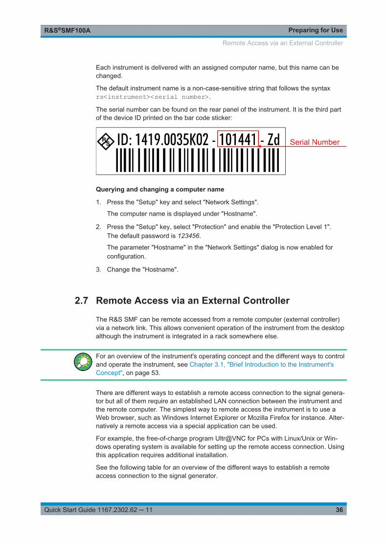
Preparing for UseR&S®SMF100A
36Quick Start Guide 1167.2302.62 ─ 11
Each instrument is delivered with an assigned computer name, but this name can bechanged.
The default instrument name is a non-case-sensitive string that follows the syntaxrs<instrument><serial number>.
The serial number can be found on the rear panel of the instrument. It is the third partof the device ID printed on the bar code sticker:
Querying and changing a computer name
1. Press the "Setup" key and select "Network Settings".
The computer name is displayed under "Hostname".
2. Press the "Setup" key, select "Protection" and enable the "Protection Level 1".The default password is 123456.
The parameter "Hostname" in the "Network Settings" dialog is now enabled forconfiguration.
3. Change the "Hostname".
2.7 Remote Access via an External Controller
The R&S SMF can be remote accessed from a remote computer (external controller)via a network link. This allows convenient operation of the instrument from the desktopalthough the instrument is integrated in a rack somewhere else.
For an overview of the instrument's operating concept and the different ways to controland operate the instrument, see Chapter 3.1, "Brief Introduction to the Instrument'sConcept", on page 53.
There are different ways to establish a remote access connection to the signal genera-tor but all of them require an established LAN connection between the instrument andthe remote computer. The simplest way to remote access the instrument is to use aWeb browser, such as Windows Internet Explorer or Mozilla Firefox for instance. Alter-natively a remote access via a special application can be used.
For example, the free-of-charge program Ultr@VNC for PCs with Linux/Unix or Win-dows operating system is available for setting up the remote access connection. Usingthis application requires additional installation.
See the following table for an overview of the different ways to establish a remoteaccess connection to the signal generator.
Remote Access via an External Controller

Preparing for UseR&S®SMF100A
37Quick Start Guide 1167.2302.62 ─ 11
Table 2-2: Remote access via an external computer
Remote access viaLAN
connec-tion
Installation of the additionalapplication
on theinstrument
on the remotecomputer
Any web browser
for example Windows Internet Explorer or Mozilla Firefox,see Chapter 2.7.1, "Using a Web Browser for RemoteAccess", on page 37
required no Java Runtime mustbe installed andactivated in the
browser settings.
Web browser with HTML5
for example LXI Browser, see Chapter 2.8.2.4, "WebControl", on page 49
required no Web sockets mustbe supported.
VNC Client
for example Ultr@VNC or other dedicated client softwarefor PCs with Linux/Unix or Windows operating system
see Chapter 2.7.2, "Remote Access via a VNC ClientSoftware", on page 38
required required VNC Viewerrequired
When the connection is set up with a VNC client software (Ultr@VNC), direct controlon the instrument is possible while remote access is established.
For return to direct operation on the instrument, the connection must be cut. After cut-ting the connection, it is still enabled and can be established again any time. The con-nection is disabled only after deactivation of the program.
This section gives an information on how to use the Web browser for remote access,how to install the applications for remote access and how to establish the connectionbetween the instrument and an external computer with Windows operating system.Remote access via an external computer with Linux/Unix operating system is per-formed accordingly.
Default passwordRemote-access and file access require the user "instrument" with default password"instrument".
Changing the default user and security passwordsIt is highly recommended to change the default user and security passwords in themenu "Setup > Security" before connecting the instrument to the network (see section"Security - Setup-Protection" in chapter "General Instrument Settings" of the OperatingManual).
2.7.1 Using a Web Browser for Remote Access
The instrument can be remote-accessed via any web browser, as for example the Win-dows Internet Explorer or Mozilla Firefox.
Remote Access via an External Controller

Preparing for UseR&S®SMF100A
38Quick Start Guide 1167.2302.62 ─ 11
Alternatively, you can also make use of the LXI browser, as described in Chap-ter 2.8.2.4, "Web Control", on page 49.
To remote access the instrument via a web browser:
1. Connect the instrument and the remote computer to a LAN, see Chapter 2.6.1,"Connecting the Instrument to the Network", on page 33.
2. Instal the Java Runtime Environment JRE on the remote computer.
3. Type the instruments' IP address in the address field of the Web browser on yourPC, e.g. http://10.111.11.1
The "VNC Authentication" screen appears.
4. Enter the password and select "OK".The default password is "instrument".
After the connection is established, the current signal generator screen with theblock diagram is displayed and the instrument can be remote-accessed from theremote computer.
2.7.2 Remote Access via a VNC Client Software
A VNC client software is an application which can be used to access and control theinstrument from a remote computer via LAN.
The following description explains how to establish the remote access, represented bymeans of the client software Ultr@VNC. The software is included in Linux/Unix operat-ing system, but it is also available as a free-of-charge download on the Internet http://www.uvnc.com/download/index.html. Thus, it is also available for remote computerswith Windows operating system.
The GUI appearance of Ultr@VNC may vary if you use a later release. Also, similarprograms may deviate in some details, but the basic procedure is the same.
Remote Access via an External Controller

Preparing for UseR&S®SMF100A
39Quick Start Guide 1167.2302.62 ─ 11
Risk of Unauthorized AccessIf the VNC service is enabled on the instrument, any user in the network who knowsthe computer name and password can access it.Disable the VNC service on the instrument to prevent unauthorized access.
Setting up a VNC connection
1. Connect the instrument and the remote computer to a LAN, see Chapter 2.6.1,"Connecting the Instrument to the Network", on page 33.
2. Install the Ultr@VNC application and enable it on the instrument.
3. In the ICF firewall, enable communication on the network via Ultr@VNC program.
4. Install the VNC Viewer on the remote computer with Windows operating system,see "Installing the VNC Viewer on a Windows PC" on page 41.
5. Set up the VNC connection between the instrument and:
a) the remote computer with Linux/Unix operating system, see "Setting up theVNC connection on the Linux/Unix remote computer" on page 41;
b) the remote computer with Windows operating system, see "Setting up the VNCconnection on the Windows remote computer" on page 42.
Enabled Direct ControlThe direct control of the instrument is not disabled and the instrument can be control-led from the front panel and via the remote computer alternately.
Installing the Ultr@VNC application
1. Download the program from the internet and copy it to a directory that can beaccessed.
2. On the instrument, shut down firmware using the ALT+F4 key combination.
3. Double click on the setup file to start the installation.The setup wizard leads through the installation. This description focus only on therelevant settings.
Remote Access via an External Controller

Preparing for UseR&S®SMF100A
40Quick Start Guide 1167.2302.62 ─ 11
a) Select installation of all components.
b) In the "Additional Task Panel", enable all entries.
A successful installation is indicated by a message.
At the same time a warning is displayed stating that a password must be set.
4. Select "OK".
The "Default Local System Properties" panel opens.
Remote Access via an External Controller

Preparing for UseR&S®SMF100A
41Quick Start Guide 1167.2302.62 ─ 11
5. Enter a password with a length of at least five digits.This password is used on the remote computer to access the instrument. Othersettings may be changed according to the user-specific security requirements.
After the installation the Ultr@VNC program is automatically started together withthe operating system. On mouse over, the IP address of the instrument is indica-ted.This IP address and the user-defined password are the prerequisites to enableremote access on the remote computer. Terminated connection is indicated bychanged icon color.
Installing the VNC Viewer on a Windows PC
1. Download the Ultr@VNC program form internet and follow the installation instruc-tions.Only the program component VNC Viewer is required.
Note: The VNC Viewer program is included in the download for the installation ofthe Ultr@VNC program on the signal generator if "Full installation" was selected inthe "Select Component" panel. In this case, the program [email protected] be copied to the Windows PC.
2. Install VNC Viewer program component on the remote computer.
Setting up the VNC connection on the Linux/Unix remote computer
The VNC program is available per default for Linux/Unix operating systems.
1. Start a Web browser on the remote computer and enter the IP address of theinstrument.
2. Enter the following address:vnc://<IP-address of the instrument>, e.g. vnc://192.168.1.1.
Remote Access via an External Controller

Preparing for UseR&S®SMF100A
42Quick Start Guide 1167.2302.62 ─ 11
A dialog is opened and the password for the remote VNC connection is requested.
3. Enter the password as defined in the "Default Local System Properties" panel ofthe Ultr@VNC program and select "Log On".
The connection is established, the instrument is remote accessed and the currentsignal generator screen with the block diagram is displayed. The individual func-tions are operated using the mouse and keyboard.In contrast to remote access via Remote Desktop, the direct control of the instru-ment is not disabled and the instrument can be controlled from the front panel andvia the remote computer alternately.
Setting up the VNC connection on the Windows remote computer
1. Start VNC Viewer program component on the PC, select "VNC Server" and enterIP address of the instrument.
2. To initialize the connection, select "Connect".
A message requesting the password appears.
3. Enter the password as defined in the "Default Local System Properties" panel ofthe Ultr@VNC program and select "Log On".
The connection is established, the instrument is remote accessed and the currentsignal generator screen with the block diagram is displayed. The individual func-tions are operated using the mouse and keyboard.
Enabled Direct ControlThe direct control of the instrument is not disabled and the instrument can be control-led from the front panel and via the remote computer alternately.
Remote Access via an External Controller

Preparing for UseR&S®SMF100A
43Quick Start Guide 1167.2302.62 ─ 11
Terminating VNC Connection
The remote access via VNC connection can be terminated either on the R&S SMF oron the external PC. Terminating the connection does not disable it. It can be estab-lished again any time. See the notice above concerning unauthorized access due toVNC connection!
1. Terminate the connection on the R&S SMF
a) Press the "Windows" key to access the operating system.b) Right-click on the VNC icon on the task bar and select "Kill all clients".
2. To terminate the connection on the external Linux/Unix PC, close the internetbrowser or close the signal generator window.
3. To terminate the connection on the external Windows PC, close the VNC Viewerprogram.
The connection is terminated. The color of the VNC icon in the status bar of theinstrument changes.A message on the external PC indicates the disconnection.
Disabling Remote Access via Ultr@VNC
The VNC connection can be disabled by removing the program on the instrument or bydeactivating the VNC Server service.
1. Remove the VNC program
a) Press the "Windows" key to access the operating system and open the "Add orRemove Programs" by selecting "Start > Settings > Control Panel > Add orRemove Programs".
b) Remove the VNC program.
2. Deactivate the VNC Server service
a) Press the "Windows" key to access the operating system and open the "Ser-vices" by selecting "Start > Settings > Control Panel > Services".
b) Deactivate the VNC Server service.
The connection is disabled, the VNC icon disappears from the task bar of theinstrument.
2.8 LXI Configuration
LXI ("LAN eXtensions for Instrumentation" is an instrumentation platform for measuringinstruments and test systems that is based on standard Ethernet technology. LXI isintended to be the LAN-based successor to GPIB, combining the advantages of Ether-net with the simplicity and familiarity of GPIB.
Like GPIB, LXI determines and standardizes the way the instrument behaves in a LAN.The LXI implementation by the Rohde&Schwarz signal generators allows you tochange certain LAN settings, to reset the LAN connection as well as to identify theinstrument easily.
LXI Configuration

Preparing for UseR&S®SMF100A
44Quick Start Guide 1167.2302.62 ─ 11
For information about the LXI standard, refer to the LXI website at http://www.lxistan-dard.org. See also "News from Rohde & Schwarz, article 2006/II - 190".
The R&S SMF provides an integrated "LXI Status" dialog for LXI status indication andreset of the LAN configuration ("LAN Configuration Initialize", LCI). To access the LXIstatus dialog, press the SETUP key and select "Remote > LXI Status".
For further information, see section "LXI Status" in the Operating Manual.
Firmware updateAfter a firmware update, shut down and restart the instrument in order to enable the fullLXI functionality.
Default state of the network settings
According to the LXI standard, an LCI must set the following parameters to a defaultstate.
Parameter Value
TCP/IP Mode DHCP + Auto IP Address
Dynamic DNS Enabled
ICMP Ping Enabled
Password for LAN configuration LxiWebIfc
The LCI for the R&S SMF also resets the following parameters:
Parameter Value
Hostname <Instrument-specific host name>
Description Vector Signal Generator
Negotiation Auto Detect
VXI-11 Discovery Enabled
The LAN settings are configured using the instrument's "LXI Browser Interface".
2.8.1 LXI Browser Settings
To access the instrument via the web browser:
► Type in the instrument's host name or IP address in the address field of thebrowser on your PC, for example "http://10.113.1.205".
LXI Configuration

Preparing for UseR&S®SMF100A
45Quick Start Guide 1167.2302.62 ─ 11
Note: Do not add the missing zeros in the IP address, while opening the instru-ment home page.
The instrument home page (welcome page) opens.
The navigation pane of the browser interface contains the following elements:● "LXI"
– "Home" opens the instrument home page.The home page displays the device information required by the LXI standard,including the VISA resource string in read-only format.
– "Device Indicator" activates or deactivates the LXI status indication.When activated, the LXI LEDs flash, both in the browser dialog and in the LXIdialog of the connected instrument. A green LXI status symbol indicates that aLAN connection has been established; a red symbol indicates that no LANcable is connected.
– "Lan Configuration" allows you to configure LAN parameters and to initiate aping, see Chapter 2.8.2.3, "Ping Client", on page 48.
– "Status" displays information about the LXI status of the instrument.– "Utilities" provides access to the LXI event log functionality required by the LXI
standard.● "Instrument Control"
– "Web Control" provides remote access to the instrument, see Chapter 2.8.2.4,"Web Control", on page 49.
● "Diagnostics"
LXI Configuration
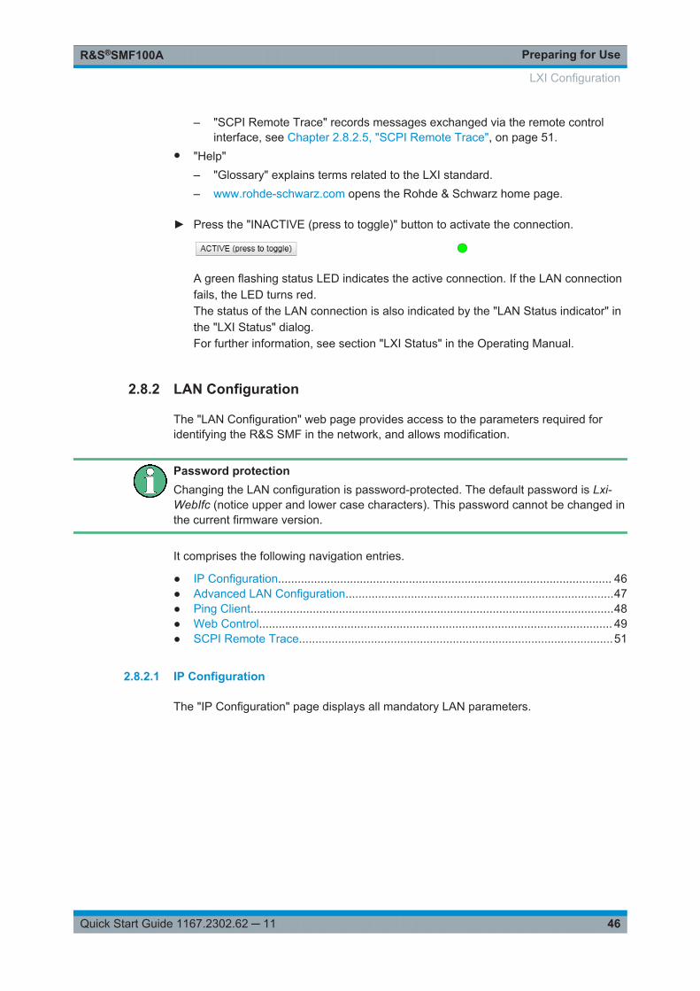
Preparing for UseR&S®SMF100A
46Quick Start Guide 1167.2302.62 ─ 11
– "SCPI Remote Trace" records messages exchanged via the remote controlinterface, see Chapter 2.8.2.5, "SCPI Remote Trace", on page 51.
● "Help"– "Glossary" explains terms related to the LXI standard.– www.rohde-schwarz.com opens the Rohde & Schwarz home page.
► Press the "INACTIVE (press to toggle)" button to activate the connection.
A green flashing status LED indicates the active connection. If the LAN connectionfails, the LED turns red.The status of the LAN connection is also indicated by the "LAN Status indicator" inthe "LXI Status" dialog.For further information, see section "LXI Status" in the Operating Manual.
2.8.2 LAN Configuration
The "LAN Configuration" web page provides access to the parameters required foridentifying the R&S SMF in the network, and allows modification.
Password protectionChanging the LAN configuration is password-protected. The default password is Lxi-WebIfc (notice upper and lower case characters). This password cannot be changed inthe current firmware version.
It comprises the following navigation entries.
● IP Configuration...................................................................................................... 46● Advanced LAN Configuration..................................................................................47● Ping Client...............................................................................................................48● Web Control............................................................................................................ 49● SCPI Remote Trace................................................................................................51
2.8.2.1 IP Configuration
The "IP Configuration" page displays all mandatory LAN parameters.
LXI Configuration

Preparing for UseR&S®SMF100A
47Quick Start Guide 1167.2302.62 ─ 11
The "IP Address Mode" selects a configuration mode for the IP address of theR&S SMF. With static configuration, the entered IP address, subnet mask, and defaultgateway are used. With dynamic configuration, DHCP or dynamic link local addressing(automatic IP) are used to obtain the instrument IP address.
See Chapter 2.6.2, "Assigning the IP Address", on page 34.
2.8.2.2 Advanced LAN Configuration
The "Advanced Config" page provides LAN settings that are not declared mandatoryby the LXI standard.
LXI Configuration

Preparing for UseR&S®SMF100A
48Quick Start Guide 1167.2302.62 ─ 11
The following advanced parameters are available:● "mDNS and DNS-SD": The additional protocols "multicast DNS" and "DNS service
discovery" are used for device communication in zero configuration networks,working without DNS and DHCP.
● "ICMP Ping enabled": Must be enabled to use the ping utility.If you disable this setting, the instrument does not answer ping requests. The set-ting does not affect the LXI ping client. You can ping other hosts from the instru-ment, even if the setting is disabled.
● "VXI-11 Discovery": Must be enabled to detect the instrument in the LAN.If you disable this setting, the instrument cannot be detected by the VXI-11 discov-ery protocol mechanism. The setting does not affect other detection mechanisms.Setting up a VXI-11 connection via the IP address or the host name is independentof this setting.
2.8.2.3 Ping Client
The "Ping Client" page provides the ping utility to verify the connection between theLXI-compliant instrument and another device.
The ping is initiated from the instrument. Using the ICMP echo request and echo replypackets, the function checks whether the communication with a device via LAN works.Ping is useful for the diagnosis of IP network or router failures.
The ping utility is not password-protected.
LXI Configuration

Preparing for UseR&S®SMF100A
49Quick Start Guide 1167.2302.62 ─ 11
To initiate a ping from the instrument to the device:
1. Enable "ICMP Ping" on the "Advanced LAN Configuration" page.
2. Select the "Ping Client" page.
3. In the "Destination Address" field, enter the IP address of the device you want toping (without the ping command and without any further parameters), e.g.10.113.1.203.
4. Select "Submit".
2.8.2.4 Web Control
The web control functionality provides remote operation via VNC using a Web browser(with HTML5). This mode does not require additional installation or activation. TheVNC protocol allows simultaneous operation from several remote devices. The instru-ment remains locally operable.
The GUI of the R&S SMF is visible. To perform the settings, you can operate theinstrument as with the manual control. The instrument controls are available via thefront panel simulation. File upload and download between the instrument and theremote PC is also available.
LXI Configuration

Preparing for UseR&S®SMF100A
50Quick Start Guide 1167.2302.62 ─ 11
Starting a Remote Control via the LXI web browser
This section assumes that the instrument and the controller PC are connected in theLAN.
1. Start a web browser that supports html5 (W3C compliant).
2. Enter the IP address of the R&S SMF in the browser's address bar.
The R&S SMF's welcome page is displayed.
3. In the navigation pane, select "Instrument Control" > "Web Control".
Remote access to the instrument requires the password. The default password isinstrument.
4. Enter the password.
5. Confirm with the ENTER key.
After the connection is established, the current screen of the R&S SMF is dis-played in the browser window.
6. Use the mouse cursor and keyboard to access the functionality of the instrumentas you would directly perform the settings on the instruments front panel.
LXI Configuration

Preparing for UseR&S®SMF100A
51Quick Start Guide 1167.2302.62 ─ 11
2.8.2.5 SCPI Remote Trace
The remote trace functionality allows you to trace input and output strings at theremote control interface of the R&S SMF.
A recorded trace (message log) can be evaluated directly in the dialog. Use the high-lighting and navigation functions provided in the lower toolbar to locate error messagesand messages containing arbitrary search strings. You can also export the messagelog to a *.csv file and evaluate the file using a suitable program.
To trace and display messages:
1. In the navigation pane, select "Diagnostics" > "SCPI Remote Trace".
2. In the toolbar bar of the "SCPI Remote Trace" page, select "live mode" > "on" and"logging" > "on".
"live mode > on" displays all commands and responses, and "logging > on" alsotraces messages.
3. If you now control the R&S SMF with SCPI commands, using an appropriate tool,the SCPI remote trace records the information sent and received.
The function records all sent commands, received responses and messages, andstores them in an internal database. If "live mode" is disabled, you can display therecent traces upon request, using the "refresh" button. You can also store the log ina file.Note: The diagnostics functionality is extended in later releases, e.g. to downloador upload SCPI command files from / to the instrument.
LXI Configuration

Preparing for UseR&S®SMF100A
52Quick Start Guide 1167.2302.62 ─ 11
Toolbars
The toolbar at the top of the dialog provides basic settings and functions.
● "Live mode" / "logging": If logging is switched on, messages are traced. They arestored in an internal database and can be displayed upon request, using therefresh button (live mode off) or they can be displayed automatically (live modeon).
● "Filter": applies a filter to columns and/or rows when working (live mode off)● "Refresh": reads the message log from the internal database and displays it● "Download": stores the SCPI trace log to a *.csv file● "Clear": deletes all message log entries in the database and on the screen● "Details": displays details of the selected message, for example an SCPI command
in hex format (also possible by double\-clicking a message)
Columns
The following columns are available if no column filter is applied:
● "Rec": record number of the message within the message log● I: number of the subinstrument● "MT": indicates the type of the message. Possible values and related message
contents are:– > = incoming command– < = outgoing response to a query– E = error message, highlighted by red color– T = execution time, i.e. time required by the instrument to process the com-
mand internally● "message": indicates the type of the message. Possible values and related mes-
sage contents are:– > = incoming command– < = outgoing response to a query– E = error message, denoted in red– T = execution time, i.e. time required by the instrument to process the com-
mand internally
LXI Configuration

Getting StartedR&S®SMF100A
53Quick Start Guide 1167.2302.62 ─ 11
3 Getting StartedThis section helps you to get familiar with the R&S SMF. It provides an introduction tothe general concept of the instrument with a sample of the possible application fields,and a description of the main blocks in the signal generation flow.
This section also explains the operating concept in general and includes a brief intro-duction to operation by a step-by-step description of the configuration. The example isintended to provide a quick overview of the settings provided. No additional equipmentis required.
3.1 Brief Introduction to the Instrument's Concept
The operating concept of the R&S SMF employs the following three ways of instru-ment control:● Manual operation● Remote control● Remote access
Manual Operation
The R&S SMF can be entirely operated from the front panel. Peripherals such asmouse or keyboard can be connected but are not essential.
The R&S SMF is equipped with an intuitive user interface. The central element of thedisplay is the block diagram that shows the signal flow and processing from the left onthe display to most right, i.e. the generated signal can be seen at a glance.
Each block represents a functional unit of the instrument. Thus you always know theposition at which a parameter affects the signal flow. The main settings of a block areindicated in the block. The interconnection of employed inputs and outputs is alsoshown. The user is thus always informed about the connection of inputs and outputs inthe signal flow and where they can be configured. A window is opened for each menuwhere parameters can be set. When the window is opened, an entry is made in the"Winbar" below the display. All open menus are of equal priority (not modal) and canbe accessed any time.
The block diagram in the figure below shows a fully equipped instrument.
Brief Introduction to the Instrument's Concept

Getting StartedR&S®SMF100A
54Quick Start Guide 1167.2302.62 ─ 11
Figure 3-1: Block diagram of a fully equipped R&S SMF
With the rotary knob, you can navigate in the block diagram and the dialogs, and oper-ate the instrument with one hand. The cursor is moved line by line through the blockdiagram or dialog. Turning the button clockwise advances the cursor. The selectedblock can be activated or deactivated with the TOGGLE key. Active blocks are high-lighted by a colored background.
The instrument comprises a comprehensive info and help system. You can access thecontext-sensitive help with the HELP (F1) key at any time. The help system indicatesthe currently selected parameter and offers additional services such as cross referen-ces, index and contents. The content of the help system corresponds to the operatingmanual of the instrument.
Warning and conflict messages caused by incorrect operation as well as further infor-mation are displayed in the "Info" line. A complete list of existing conflicts is displayedwhen the INFO (CTRL+I) key is pressed. Additional information on entries can berequested from the help system. The history function permits display of all messages.
Assistants simplify the completion of tables. After data entry in the assistant, the tableis modified only after the "Accept" button has been pressed. Pressing the "Accept" but-ton also stores the assistant data.
For an introduction into the manual operating of the instrument, detailed operatinginstructions and an overview of menus refer to Chapter 4, "Manual Operation",on page 67.
For an in-depth description of the dialog boxes and the instrument functions, refer tosection "Instrument Functions" in the operating manual.
Brief Introduction to the Instrument's Concept

Getting StartedR&S®SMF100A
55Quick Start Guide 1167.2302.62 ─ 11
Remote Control
Remote control is an operation of the instrument by means of remote control com-mands or programs that automatize repeating settings. The instrument is connected toa computer running the program.
The R&S SMF supports various remote control connections:● Connecting the instrument to a (LAN) network● Using the LXI browser interface in a LAN network● Connecting a PC via the IEC-bus (IEEE 488) interface● Remote control via the USB interface
Tip: For remote control over LAN or USB, you can use the R&S VISA (Virtual Instru-ment Software Architecture) library provided for download at the Rohde & Schwarzwebsite http://www.rohde-schwarz.com/rsvisa.
This way of operation and the instructions how to set up a connection for remote con-trol are described in the operating manual, chapter "Remote Control Basics". Thedescription of the remote control commands is provided in the operating manual, chap-ter "Remote Control Commands".
Remote access
Remote access is the operating of the instrument from a remote computer. Both theR&S SMF and the computer are connected in a LAN.
Remote access in contrast to remote control does not use remote-control commandsbut a separate software which is installed on the remote computer. After its start, thesoftware simulates the user interface of the instrument. The instrument can thus beoperated from the remote computer as on the unit itself. The individual functions areoperated using the mouse and keyboard. Specific instrument functions can be execu-ted using specific key combinations on the keyboard or a front panel key emulation thatcan be operated with the mouse.
This way of operation and the instructions how to set up a connection for remoteaccess are described in Chapter 2.7, "Remote Access via an External Controller",on page 36.
3.2 Application Field of the Instrument
The main field of application of the R&S SMF is the generation of microwave signalswith very high spectral purity. The signals can be generated with a set frequency andlevel (CW mode), based on a list with predefined frequency/level pairs (List mode), oras a sweep with corresponding parameters (Sweep mode).
The RF signal can also be generated in modulated form. Option R&S SMF-B20 pro-vides two internal LF generators, a noise generator and two external modulation inputsEXT 1 and EXT 2 at the front of the instrument which are available as the source for
Application Field of the Instrument

Getting StartedR&S®SMF100A
56Quick Start Guide 1167.2302.62 ─ 11
analog and/or digital modulations. Option R&S SMF-K23 provides an internal pulsegenerator.
3.3 Description of Individual Diagram Blocks
Up-to-date information is available at R&S SMF homepage on the internet http://www.rohde-schwarz.com/product/smf100a.html).
RF Frequency blockIn this block, the RF frequency settings are performed.
RF settings include:● RF frequency and phase settings● Frequency sweep settings including sweep markers● List mode settings● Reference oscillator settingsNote: Numeric values for frequency are entered best and quickest with the aid of theFREQ key.Use the RF ON/OFF key to switch the RF output on or off.
Level Control blockIn this block, the RF level settings are performed.
RF level settings include:● RF level settings● RF level sweep settings including sweep markers● Automatic level control● NRP-Z Power Viewer using power sensors● NRP-Z Power and Pulse Data Analysis using power sensors● User CorrectionNote: Numeric values for the level are entered best and quickest with the aid of theLEVEL key.
Modulation blockIn this block, the modulation settings are performed. The MOD ON/OFF key switchesthe active modulation(s) on/off.
The external inputs EXT 1 and EXT 2 at the front of the instrument are provided forexternal amplitude, frequency, phase, and digital modulation (ASK, FSK, PSK).
Pulse modulation is available via the internal standard pulse generator. The externalpulse modulation is available via the PULSE IN connector at the front of the instru-ment. The connector can be used as trigger input for internal pulse modulation. Theexternal (and internal) pulse signal is output at the VIDEO connector at the back of theinstrument.
Description of Individual Diagram Blocks

Getting StartedR&S®SMF100A
57Quick Start Guide 1167.2302.62 ─ 11
Internal Pulse Modulation with extended features, e.g. generation of double pulse,requires option R&S SMF-K23, Pulse Generator. The pulse signal is output at thePULSE OUT connector at the front of the instrument. Narrow pulse modulation is provi-ded by option R&S SMF-K3, and pulse train by option R&S SMF-K27.
Note: For an overview of the modulation modes that can be simultaneously used, referto the data sheet or to section "Simultaneous Operation of Several Modulations orOther Operating Modes" in the Operating Manual.The status display in the block shows the active modulation(s).
Use the TOGGLE ON/OFF key to switch the modulation on or off.
LF Gen./Noise blockIn this block, two internal LF generators and a noise generator which can be used asinternal modulation sources for analog modulations (amplitude modulation, frequencymodulation, phase modulation) are configured. The LF/noise generators can also beused as the signal source for the LF output at the rear of the instrument.
The LF frequency sweep is also configured in this block.
LF Output blockIn this block, the LF output and the LF level sweep are configured.
The internal LF generators, the noise generator, or the external inputs EXT 1 andEXT 2 can be selected as source for the LF output.
Pulse Gen. blockIn this block, the settings for the internal pulse generator can be performed.
The pulse generator provides single and double pulse modulation with selectable pulsewidths and periods. The signal is output at the PULSE OUT connector.
Pulse Mod. blockIn this block, the narrow pulse modulation is activated and configured. Narrow pulsemodulation requires option R&S SMF-K3.
Attenuator blockIn this block, the attenuator settings for the RF signal are performed.
SMZxxx blockBy connecting an R&S SMZ75/90/110/170 Frequency Multiplier, the R&S SMF indi-cates a separate block for the frequency multiplier. The block shows the model of thefrequency multiplier and its associated frequency range.
The model of the multiplier is differentiated in the header of the block:● "SMZ-BxxxE" with electronical level control
● "SMZ-BxxxM" with a mechanical level control
Description of Individual Diagram Blocks

Getting StartedR&S®SMF100A
58Quick Start Guide 1167.2302.62 ─ 11
In models with mechanical level control, the frequency range in the footer changesto the corresponding scale-setting for the adjusting screw.
● "SMZxxx" without level control
Depending on the model of the frequency multiplier the R&S SMF adjusts the RF fre-quency and level automatically to the frequency multiplier, and shows the values in theheader. Accordingly, further adjustments can be made in this block. For information indetail, see the manual of your R&S SMZ75/90/110/170.
3.4 Example of Setup
This section provides an example on how to configure the instrument for generating ofan amplitude modulated signal and of a frequency modulated signal with noise.
Generation of an Amplitude-Modulated Signal
To generate a simple AM-modulated signal, proceed as follow:
1. Activate default (preset) statePress the PRESET key to set a defined instrument state.
Example of Setup

Getting StartedR&S®SMF100A
59Quick Start Guide 1167.2302.62 ─ 11
2. Select and activate AM modulation
a) Turn the rotary knob and select the "Modulation" block.
b) Press the rotary knob to open the dialog where the modulation can be selected(different modulation modes are available depending on the options installed).
Example of Setup

Getting StartedR&S®SMF100A
60Quick Start Guide 1167.2302.62 ─ 11
c) Turn the rotary knob and highlight "Amplitude Modulation".Press the rotary knob to open the "Amplitude Modulation" dialog.
d) Turn the rotary knob to select parameter "Depth", press the rotary knob to allowediting and enter the preffered AM depth with the aid of the numeric keypadand the unit keys.
Example of Setup

Getting StartedR&S®SMF100A
61Quick Start Guide 1167.2302.62 ─ 11
e) Finally, select "State" and press the rotary knob to switch on the AM modula-tion.
f) Press the DIAGRAM key to display the complete block diagram.
To indicate the active state, the "Modulation" block is displayed in blue. The "RFFrequency" is not yet active, which means that no RF signal is output.
3. Set frequency and level and activate RF signal
a) Press the FREQ key to activate the editing mode for frequency entry. The "Fre-quency" entry field in the header section of the display is highlighted.
Enter the frequency of the desired RF carrier using the numeric keypad andterminate the entry by pressing a unit key.
b) Press the LEVEL key and enter the level settings in the same way.
c) Press the DIAGRAM key to display the complete block diagram.d) Turn the rotary knob to select the "RF Frequency" block.
Press the RF ON/OFF key to activate the "RF Frequency" block.
The AM modulation signal is now present at the RF output.
Example of Setup

Getting StartedR&S®SMF100A
62Quick Start Guide 1167.2302.62 ─ 11
Generation of a Frequency Modulated Signal with Noise
To generate a simple FM-modulated with noise signal, proceed as follow:
1. Activate default (preset) statePress the PRESET key to set a defined instrument state.
Example of Setup

Getting StartedR&S®SMF100A
63Quick Start Guide 1167.2302.62 ─ 11
2. Select and activate FM modulation with internal noise signal and a deviation of 500kHz
a) Turn the rotary knob and select the "Modulation" block.
b) Press the rotary knob to open the dialog where the modulation can be selected(different modulation modes are available depending on the options installed).
c) Turn the rotary knob and highlight "Frequency Modulation".Press the rotary knob to open the "Frequency Modulation" dialog.
The internal source is the LF generator 1 by default. This setting is notchanged.
Example of Setup

Getting StartedR&S®SMF100A
64Quick Start Guide 1167.2302.62 ─ 11
d) Turn the rotary knob to select parameter "Source", press the rotary knob toopen the selection list and select "Noise Generator".
The settings for the noise generator are performed in the "LF Gen./Noise"block. Gauss distribution and full bandwidth (10 MHz) are the default settingsfor the noise signal.
e) Turn the rotary knob to select parameter "Deviation", press the rotary knob toallow editing and enter the preffered deviation with the aid of the numeric key-pad and the unit keys.
Example of Setup

Getting StartedR&S®SMF100A
65Quick Start Guide 1167.2302.62 ─ 11
f) Finally, select "State" and press the rotary knob to switch on the FM modula-tion.
g) Press the DIAGRAM key to display the complete block diagram.
To indicate the active state, the "Modulation" block is displayed in blue. The "RFFrequency" is not yet active, which means that no RF signal is output.
3. Set frequency and level and activate RF signal
a) Press the FREQ key to activate the editing mode for frequency entry. The "Fre-quency" entry field in the header section of the display is highlighted.
Enter the frequency of the desired RF carrier using the numeric keypad andterminate the entry by pressing a unit key.
b) Press the LEVEL key and enter the level settings in the same way.
The noise now modulates the RF carrier.c) Press the DIAGRAM key to display the complete block diagram.d) Turn the rotary knob to select the "RF Frequency" block.
Press the RF ON/OFF key to activate the "RF Frequency" block.
The FM modulation signal is now present at the RF output. The LF output is not yetactivated, i.e, the modulation signal is not output there.
Example of Setup

Getting StartedR&S®SMF100A
66Quick Start Guide 1167.2302.62 ─ 11
The graph below shows the FM modulated signal with noise (upper blue trace) andthe unmodulated signal (lower greentrace).
Example of Setup

Manual OperationR&S®SMF100A
67Quick Start Guide 1167.2302.62 ─ 11
4 Manual OperationThe R&S SMF can be operated intuitively either via the interactive block diagram or viaa menu tree. All menus are in the form of windows that can be operated in the sameway. Rotary knob, keys and softkeys, or alternatively a mouse, allow direct and there-fore convenient access to entries and settings.
The clear-cut display shows the current signal generator state. Numerous help func-tions support the user in signal configuration.
This section describes the concept of manual operation of the signal generator. Thisincludes a description of the general structure of a dialog box, working with dialogboxes and the block diagram and the setting of parameters.
For an in-depth description of the dialog boxes and the instrument functions refer tosection "Instrument Functions" in the Operating Manual.
4.1 Key Features
The manual operating concept of the R&S SMF enables the user to make settings asintuitively as possible and at the same time gives a permanent overview of characteris-tics of the generated signal and of the current instrument state. Numerous online helpfunctions support user settings.
Block diagram
The block diagram is the core of the operating concept.
A graphics display shows the current configuration and the signal flow in the form of ablock diagram. All graphical elements can be accessed for operation. An element isselected by means of the arrow keys and the associated setting function is called bypressing Enter. Required menus and graphs are displayed on the block diagram whichis displayed again in the foreground whenever the DIAGRAM (CTRL+D) key ispressed.
Permanent frequency and level display
The main characteristics of the RF signal, frequency and level, are permanently dis-played in the header section of the screen and can be directly set in the display fieldsafter the FREQ (CTRL+F) or LEVEL (CTRL+L) key is pressed. Status messages forthe output signal are displayed in addition to frequency and level.
Operation via Graphical User Interface
● Functional blocksMenus are assigned to the specific function blocks in the block diagram. The func-tion blocks represent elements of signal generation. Function blocks displayed with
Key Features

Manual OperationR&S®SMF100A
68Quick Start Guide 1167.2302.62 ─ 11
a blue frame can be directly switched on and off by means of the TOGGLEON/OFF (CTRL+T) key. The menus of the highlighted function blocks can becalled by pressing the ENTER key.– Example:
The "Modulation" block contains all menus required for modulation signal con-figuration.
In this block all modulations can be selected.
● Signal flowThe signal flow between the function blocks and the employed inputs and outputsare also shown.
● Menu treeThe menu tree can be opened and closed with the MENU (CTRL+M) key. Themenu tree is organized in the same way as the directories under Windows. Thefunction blocks correspond to the first directory level, the menus to subdirectories.
Key Features

Manual OperationR&S®SMF100A
69Quick Start Guide 1167.2302.62 ─ 11
Operation corresponds to the Windows concept
To offer the user a familiar environment, operation is very similar to operation of Win-dows user interfaces. All menus and tables are made up of known elements, such asselection lists, check boxes and entry fields.
A blue frame indicates that the selected item is active. In the highlighted element,entries can be made.
Rotary knob
Operation is possible via front-panel keys, an external keyboard and the mouse. How-ever, most of the settings can be easily made with the rotary knob:
● Turning the rotary knob shifts the entry focus to the target element.
● Pressing the rotary knob activates the selected entry field.Depending on the parameter, the submenu is called, the numeric value varied, thelist entry selected or the check box activated or deactivated.
● If a value is entered, the entry is stored by another click on the rotary knob and theediting mode is exited.
Clear settings with the aid of independent subdialogs
A separate window is opened for each dialog and subdialog. The dialogs can be oper-ated independently of each other, i.e. none of the dialogs requires that settings in otherdialogs be completed before it can be closed. This ensures flexible operation at alltimes.
Winbar
The Winbar gives an overview of menus and simplifies their access.
The menus are displayed on top of the block diagram but they can be "hidden" usingthe DIAGRAM key. They can be displayed again in full size (WINBAR key). Thismakes room on the screen for other displays that may be required but the settingmenus can thus be accessed any time.
Key Features

Manual OperationR&S®SMF100A
70Quick Start Guide 1167.2302.62 ─ 11
Keys with assigned simple functions
Most keys on the front panel of the R&S SMF directly perform a simple function.
Since a great number of settings can thus be made by a keystroke, operation is easy.For instance, the CLOSE (ESC) key closes the active menu; with the RF ON/OFF(CTRL+R) key the RF output signal can be switched on or off.
An exception are keys that call a menu such as the MENU (CTRL+M) key which opensthe complete menu tree of the instrument, the SETUP (CTRL+E) key which opens themenus for general instrument settings or the FILE (CTRL+S) key which opens themenu for file management.
Help functions for user support
Numerous help functions support the user in signal configuration.
● Value rangesThe valid setting range is displayed for each numeric parameter. This requires ashort wait after activation of the entry field. The range is then displayed automati-cally after a few seconds.
If the entered value is outside the permissible range, the next permissible value isautomatically set and a message is output.
● Context-sensitive helpContext-sensitive help for each parameter can be called with the HELP or F1 key.
● Comprehensive online helpEach help page is part of a comprehensive online help function which can becalled by means of an index, a content tree or the "Previous/Next" buttons.
Info line with messages for indication of the current instrument state
A great variety of different messages such as status messages, error messages, warn-ings or information are displayed in the header field of the screen. With the aid of theINFO (CTRL+I) key, help pages can be called for most of the messages. They providebackground information on the message and indicate operating steps that may berequired. All messages are explained in the online help which can be called with theHELP (F1) key.
Key Features

Manual OperationR&S®SMF100A
71Quick Start Guide 1167.2302.62 ─ 11
4.2 Display
The display shows the current signal generator state and offers graphical elements fordirect operation. It is divided into three sections:● The frequency and level display with info line indicates the main output signal
parameters and reports the current state with status, error and warning messages.● The block diagram shows the instrument configuration, the signal characteristic as
well as the inputs and outputs used and permits interactive operation via graphicselements. Active menus and graphs are displayed on top of the block diagram.
● Winbar with labeled softkeys for menu display.
The block diagram in the figure below shows a fully equipped instrument.
Figure 4-1: Block diagram of a fully equipped R&S SMF
4.2.1 Settings Displayed in the Header Section
Frequency/level settings and a few status messages (see Chapter 4.2.2, "Status Infor-mation and Messages", on page 72) are displayed in the header field of the screen.The display may vary depending on the instrument's operating mode:● In the sweep mode, the current frequency or level of the output signal is displayed.
The status message "SweepMode" is displayed in the info line.● In the list mode, neither the current frequency nor level is displayed, the indication
is dimmed.● If user correction is active, the status message "UCorr" is displayed in the info line.
Display

Manual OperationR&S®SMF100A
72Quick Start Guide 1167.2302.62 ─ 11
The values displayed in the "Freq" and "Level" fields include a set offset or multiplierfactor.See also "RF Frequency and Phase" and "RF Level" in the Operating Manual.
4.2.2 Status Information and Messages
The instrument indicates status information and messages in the header section of thescreen. The messages differ with respect to their importance (errors, warnings, info)and the time of their appearance (brief and permanent messages), and require differ-ent treatment
For additional information refer to the info window (see Chapter 4.2.3, "Info Window",on page 73).
Refer to "Error messages" in the Operating Manual for an overview of all status infor-mation and messages and corrective actions.
4.2.2.1 Status Information
The status information gives the user an overview of the main operating states and set-tings of the instrument. The states are indicated for information only and do not neces-sitate any action by the user.
Status information is displayed between the frequency and level fields, at the left of theinfo line or in the info line itself.
4.2.2.2 Messages
Messages indicate errors in the instrument. They are displayed in the info line in differ-ent colors depending on their importance and display duration. Errors (e.g. no calibra-tion data) are displayed in red, information (e.g. file not found) and warnings in black.Warnings indicate less significant errors (e.g. the instrument operates outside specifieddata).
4.2.2.3 Volatile messages
Brief messages report automatic settings in the instrument (e.g. switching off of incom-patible types of modulation) or on illegal entries that are not accepted by the instrument(e.g. range violations). They are displayed in the info line on a yellow background.They are displayed on top of status information or permanent messages.
Volatile messages do not normally demand user actions and disappear automaticallyafter a brief period of time. They are stored in the history, however.
These messages can be read from remote using SYST:ERR? or SYST:ERR:ALL?.
Display

Manual OperationR&S®SMF100A
73Quick Start Guide 1167.2302.62 ─ 11
4.2.2.4 Permanent Messages
Permanent messages are displayed if an error occurs that impairs further instrumentoperation, e.g. a hardware fault. The error signalled by a permanent message must beeliminated before correct instrument operation can be ensured.
The message is displayed until the error is eliminated. It covers the status display inthe info line. After error elimination, the message automatically disappears and is alsorecorded in the history.
These messages can be read from remote using SYST:SERR?.
4.2.3 Info Window
A few operating states and the current message are displayed in the info line.
The INFO window with a list of current permanent messages and a detailed descriptionof each message can be opened with the INFO (CTRL+I) key.
The upper section of the info window contains a list of all current permanent messagesin the order of their occurrence, i.e. the most recent message is displayed first. In thelower section of the window, additional information on the highlighted message is dis-played. A history of all messages that have occurred since instrument switch-on can becalled with the "History" key. The most recent message is displayed first.
The messages are color-coded according to their level. Device-specific messages arered, info and remote control error are black. The level is also indicated in the "Lev"column (Err, Sys or Info). Column "SCPI" indicates the SCPI error code.
With the aid of the softkey buttons, error messages can be cleared and a history of allmessages called.
DeleteClears the highlighted message.
This button is available only if the history of the messages is displayed.
Delete AllClears all messages.
This button is available only if the history of the messages is displayed.
Display

Manual OperationR&S®SMF100A
74Quick Start Guide 1167.2302.62 ─ 11
Del. volatileClears all volatile messages.
This button is available only if the history of the messages is displayed.
Remote command: SYST:ERR:ALL?Each time a SYST:ERR:ALL? query is sent, the error queue is returned and at thesame time cleared.
HistoryCalls the list of all messages that have occurred since instrument switch-on. The mostrecent messages are displayed at the top of the list. When the button is pressed again,the list of current messages is displayed.
Remote command: SYST:ERR? or STAT:QUE?Each time a SYST:ERR? or STAT:QUE? query is sent, the oldest entry in the errorqueue is returned and at the same time cleared in the list.
4.2.4 Block Diagram
The block diagram shows provided options, signal configuration and the currentlyselected signal flow of the generator with inputs and outputs used. Signal generationcan be completely operated from the block diagram. The highlighted function block canbe directly switched on and off with the TOGGLE ON/OFF (CTRL+T) key. Pressing theEnter opens the associated setting menu.
Figure 4-2: Block diagram of the R&S SMF
4.2.4.1 Function Blocks in the Block Diagram
Each block represents a function of signal generation. The function is indicated in theheadline of the block. In the check box, the respective function can be quickly activa-ted/ deactivated with the TOGGLE ON/OFF (CTRL+T) key. After activation, the block
Display
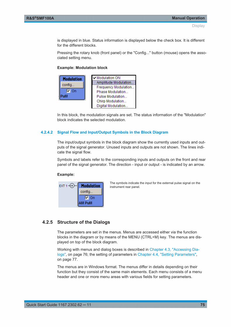
Manual OperationR&S®SMF100A
75Quick Start Guide 1167.2302.62 ─ 11
is displayed in blue. Status information is displayed below the check box. It is differentfor the different blocks.
Pressing the rotary knob (front panel) or the "Config..." button (mouse) opens the asso-ciated setting menu.
Example: Modulation block
In this block, the modulation signals are set. The status information of the "Modulation"block indicates the selected modulation.
4.2.4.2 Signal Flow and Input/Output Symbols in the Block Diagram
The input/output symbols in the block diagram show the currently used inputs and out-puts of the signal generator. Unused inputs and outputs are not shown. The lines indi-cate the signal flow.
Symbols and labels refer to the corresponding inputs and outputs on the front and rearpanel of the signal generator. The direction - input or output - is indicated by an arrow.
Example:
The symbols indicate the input for the external pulse signal on theinstrument rear panel.
4.2.5 Structure of the Dialogs
The parameters are set in the menus. Menus are accessed either via the functionblocks in the diagram or by means of the MENU (CTRL+M) key. The menus are dis-played on top of the block diagram.
Working with menus and dialog boxes is described in Chapter 4.3, "Accessing Dia-logs", on page 76; the setting of parameters in Chapter 4.4, "Setting Parameters",on page 77.
The menus are in Windows format. The menus differ in details depending on theirfunction but they consist of the same main elements. Each menu consists of a menuheader and one or more menu areas with various fields for setting parameters.
Display

Manual OperationR&S®SMF100A
76Quick Start Guide 1167.2302.62 ─ 11
The header line contains the name of the menu and the buttons for minimizing andclosing the menu. To operate the buttons, use the mouse or the front key CLOSE(ESC).
Several fields of associated but separately set parameters are organized in menuareas. A menu area is framed and labelled with the function common to all parameters.
Example: Pulse Generator
Each of the setting fields is assigned a parameter name. The kind of setting variesdepending on the parameter to be set. Some settings can only be made in a specificconfiguration. If setting is not permitted with the specific configuration selected, therespective item is disabled and displayed in gray and the entry or selection field cannotbe accessed.
4.3 Accessing Dialogs
The MENU (CTRL+M) key opens the complete menu tree. Selecting a functional blockand pressing the ENTER key opens the menu associated with this block.
An alternatively way to access a dialog is to use the Winbar buttons or front-panel soft-keys or to use the HIDE (CTRl+H), CLOSE (ESC), DIAGRAM (CTRL+D) and REARR(CTRL+A) keys on the front panel.
For a quick access to the dialogs, use one of the following alternative methods.
Displaying the block diagram or a dialog in the foreground
1. Press the DIAGRAM (CTRL+D) key to move the cursor to the block diagram.
All active menus are minimized and displayed in the form of Winbar buttons.
2. Press the associated softkey (CTRL+F1 .. F8) to display the dialog in the fore-ground again.
Accessing the menu tree
► Press the MENU (CTRL+M) key to open the complete menu tree.
Calling the File, Setup or Hardcopy dialogs
► Use the FILE (CTRL+S), SETUP (CTRL+E) or HCOPY (CTRL+Y) keys to open therespective dialog.
Accessing Dialogs

Manual OperationR&S®SMF100A
77Quick Start Guide 1167.2302.62 ─ 11
Minimizing an active menu
► Use the HIDE (CTRL+H) key to minimize an active menu.
It is displayed in the form of a Winbar button.
Automatically arranging displayed menus
► Press the REARR (CTRL+A) key to rearrange all open menus so that they overlapas little as possible.
Activating the Winbar
► Use the WINBAR (CTRL+W) key to toggle the cursor between a button of the"Winbar" and the block diagram.
The button that was active last in the Winbar is highlighted.
Closing an active menu
► Press the CLOSE key to close an active menu.
Tip: If the cursor is at the highest menu level, you can also use the ESC key toclose the active menu.
Accessing the header area
► Press the FREQ (CTRL+F) and LEVEL (CTRL+L) keys to activate the "Frequency"or "Level" entry fields in the header area.
Keyboard ShortcutsKeyboard shortcuts (e.g. "Ctrl + D" for the displaying the block diagram in the fore-ground) provide direct access to all utility dialogs of the instrument (see Chapter 4.8,"Legend of Front-Panel Controls", on page 91).
4.4 Setting Parameters
The R&S SMF offers several and sometimes alternative possibilities for setting param-eters. Operation is possible from the front panel, with the aid of a mouse and/or from aPC keyboard.
The examples whitin this description focus on the operation from the front panel.
Setting Parameters

Manual OperationR&S®SMF100A
78Quick Start Guide 1167.2302.62 ─ 11
For more information, refer to:● Chapter 4.8, "Legend of Front-Panel Controls", on page 91 for an overview of key
functions and a cross-reference between the front panel keys and the keyboardshortcuts
● "Instrument Functions" in the Operating Manual for a detailed description of keyfunctions.
Most of the parameters are set in the different menus. The R&S SMF provides alterna-tive ways for accessing the dialogs. Turn the rotary knob and navigate to the corre-sponding block in the block diagram and press the knob to open the dialog or performa mouse click on the "Config..." button.
An exception are the "Setup", "File" and "Hcopy" dialogs. In the "Setup" dialog, generalsettings are made which are not directly concerned with signal generation, e.g. settingof the GPIB-bus address. In the "File" dialog, files and lists are managed; in the"Hcopy" dialog, printout is configured and hardcopies can be made. These menus canonly be called with the SETUP (CTRL+E), FILE (CTRL+S) and HCOPY (CTRL+Y)keys.
Frequency and level are directly set in the header area of the display using the FREQand LEVEL keys.
Specific settings can also be made directly in the block diagram, e.g. activating a func-tion block by means of the TOGGLE ON/OFF (CTRL+T) key or switching the RF out-put on and off with the aid of the RF ON/OFF (CTRL+R) key. Changes affecting thesignal flow are immediately visible in the graphics display.
This section provides an information about the parameter handling that comprises ofthe following main steps:● Chapter 4.4.1, "Working with the Cursor", on page 78● Chapter 4.4.2, "Selecting a Control Element", on page 79● Chapter 4.4.3, "Switching Parameters On/Off", on page 79● Chapter 4.4.4, "Entering a Value", on page 80● Chapter 4.4.5, "Working with Units ", on page 81● Chapter 4.4.6, "Selecting a Value from a List", on page 82● Chapter 4.4.7, "Terminating Entries with Confirmation", on page 82● Chapter 4.4.8, "Restoring the Previous Value", on page 83
4.4.1 Working with the Cursor
After the instrument is switched on, the cursor is always on the first function block ofthe diagram (default setting).
Moving the cursor on the display
► To move the cursor, use one of the following alternative methods:
a) Use the rotary knob or the arrow keys.
Setting Parameters

Manual OperationR&S®SMF100A
79Quick Start Guide 1167.2302.62 ─ 11
b) Use the appropriate softkeys (CTRL+F1..F8) to move the cursor to the "Win-bar".If the "Winbar" is covered by a menu, press the WINBAR (CTRL+W) key to dis-play it in the foreground.
c) Use the ESC key.
Tip: Be aware that the function of the ESC key depends on the current cursor posi-tion.The function of this key depends on the current cursor position.● Calls the next higher selection level.● Closes the open window without accepting new entries; the old value or param-
eter is retained.● In dialog boxes that contain a "Cancel" button it activates that button.● Closes all kinds of dialog boxes, if the edit mode is not active.● Quits the edit mode, if the edit mode is active.● Switches between different entry fields of a menu.● Shifts the entry cursor from the header display to the previously active menu, or
to the previously highlighted block in the block diagram if no menu is active.
Moving the coursor to the heading area
► Press the FREQ (CTRL+F) or LEVEL (CTRL+L) key to move the cursor to theheader area.
4.4.2 Selecting a Control Element
Control elements are always selected in the same way no matter whether a functionblock in the diagram, a menu in the menu tree, a parameter in the menu or an entry ina list or table is concerned.
► To activate an element, put the cursor on it.
An active element is highlighted by a blue frame.
4.4.3 Switching Parameters On/Off
A parameter can be activated and deactivated using a button or a check box.
1. Select the parameter.
2. To change the state of a parameter, use the "Enter" function of the different controlmedia:● Press the rotary knob● Press ENTER
Setting Parameters

Manual OperationR&S®SMF100A
80Quick Start Guide 1167.2302.62 ─ 11
● Press the TOGGLE ON OFF (CTRL+T) key.
Colour and label of a button change, the check box is ticked or the tick is removed.
4.4.4 Entering a Value
Numeric and alphanumeric values can be edited in the entry fields. In the editingmode, cursors of different colour are used. A blue cursor indicates the overwrite mode,a green cursor the insert mode.
Numeric and alphanumeric values can either be newly entered or the existing valuecan be changed. Incorrect entries are cleared with the BACKSPACE key.
Entering a new numerical value
1. Select the parameter.
2. Press a numeric key to activate the editing mode.
The previous value is cleared and the new value can be entered.
Editing a value in the insert mode (default setting)
1. Press the rotary knob (= Enter) to activate the editing mode.
If the cursor is placed at the right of the total value, the insert mode is alwaysactive.
2. Set the cursor to the left of the number to be changed using the LEFT/RIGHTarrow keys.
The cursor is displayed in green.
3. Click on a numeric key to insert a new value.
Editing a value in the overwrite mode
1. Activate the editing mode.
2. Set the cursor on the numeric digit to be changed using the LEFT/RIGHT arrowkeys.
The cursor is displayed in blue and the number to be replaced is highlighted.
3. Click on a numeric key to overwrite the highlighted value.
Varying a value
1. Activate the editing mode.
2. Set the cursor to the left of the number to be changed using the LEFT/RIGHTarrow keys.
Setting Parameters

Manual OperationR&S®SMF100A
81Quick Start Guide 1167.2302.62 ─ 11
The value at the cursor position is varied.
3. To vary the selected value, use the UP/DOWN arrow key or turn the rotary knob.
The value is increased or decreased.
Entering a new alphanumerical value
1. Select the parameter.
2. Press an alphanumeric key to start the editing mode.
The new value is entered.
Editing an alphanumerical value
An existing value, e.g. a file name, can be changed in the insert mode (see example)or in the overwrite mode.
1. Select the paramter and activate the editing mode.
2. Set the cursor to the left of the alphanumerical value using the LEFT/RIGHT arrowkeys.
Tip: If hexadecimal values are to be entered, the numeric front-panel keys areautomatically changed to hexadecimal values.
3. Click on an alphanumeric key to insert a new alphanumerical value.
Terminating the entry of a numeric value
To terminate the entry of a numeric value:
1. Press the rotary knob (= Enter).
2. Press a UNIT key on the front panel.
3. Select a "Unit" in the selection field next to the parameter value.
4.4.5 Working with Units
The unit of a parameter is displayed next to the value. When the parameter is edited,the unit is selected either from the list or by means of the front-panel keys. When theentry is completed, the unit can be changed. In this case the value remains unchangedbut is automatically adapted to the new unit.
While operating the instrument by means of a mouse, assign the unit to the selectedparameter before entering its value.
Assigning a unit
To assign a unit to a value, use one of the following alternatives:
1. Press a UNIT key on the front panel.
Setting Parameters

Manual OperationR&S®SMF100A
82Quick Start Guide 1167.2302.62 ─ 11
2. Select a "Unit" in the selection field next to the parameter value.Press the ENTER key.
The unit displayed in the entry field next to the value is assigned.
Changing a unit
To subsequently change a unit, i.e. after the entry has been terminated and when theediting mode is not active, use one of the following alternatives:
1. Press a UNIT key on the front panel.
2. Select"Unit" in the selection field next to the parameter value.
The value remains unchanged but the display is automatically adapted to the newunit, i.e. the value is recalculated to suit the new unit.
The new unit is indicated in the value field of the menu.
4.4.6 Selecting a Value from a List
Selection lists provide a list of predefined values for the selected parameter.
To select a item from a list, proceed as follow:
1. Press ENTER key to open the list.
2. Use one of the following alternatives to navigate through the list:
a) Turn the rotary knob or use the UP/DOWN arrow keys.The selected item is highlighted.
b) Press TOGGLE ON/OFF key several times until the preferred entry is dis-played in the selection field.
3. To confirm the selection, press the ENTER key.
4.4.7 Terminating Entries with Confirmation
The instrument behaves different by the termination of entries deppending on theparameter type and the way this parameter is set.
Setting Parameters

Manual OperationR&S®SMF100A
83Quick Start Guide 1167.2302.62 ─ 11
Confirming settings
► To confirm the settings, press the rotary knob or one of the UNIT keys (see alsoChapter 4.4.5, "Working with Units ", on page 81) .
Note: Variations by means of the rotary knob are immediately set.
Confirming multiple values
In some cases, like for instance when editing data in a user correction table, it is usefulfirst to enter few values and to confirm them together. Such settings require additionalconfirmation. Not yet confirmed settings are displayed on a yellow background as anindication that the currently displayed values do not represent the target signal.
► To confirm these settings, select the "Save" or "Accept" button, respectively.
Confirming parameters with On/Off state
Most of the instrument functions with enabled and disabled states are calculated andeffective only after this functions have been enabled. However, there are functions likethe frequency variation of the reference oscillator for instance, that are immediately setafter confirmation.
► To confirm a parameter with On/Off state, enable the parameter.
4.4.8 Restoring the Previous Value
Parameter variations with the rotary knob are immediately set and therefore not rever-sible.
Normally, values cannot be restored in the case of mouse control because no explicitconfirmation is required in this case and entries are automatically confirmed when theentry or selection field is exited.
Restoring values
In the case of front-panel control or operation from the keyboard, previous values canbe restored as long as the new value is not confirmed, i.e. the entry is not completed.
► To restore the values, press the ESC key.
Restoring values that require confirmation
All settings that are not confirmed with the "Accept" button but require this additionalconfirmation can be restored.
1. Press the ESC key.
A confirmation query is displayed.
Setting Parameters

Manual OperationR&S®SMF100A
84Quick Start Guide 1167.2302.62 ─ 11
2. Confirm with "OK" to abort the changes.Select "Cancel" to return to the dialog. The previous selected settings are dis-played.
Restoring values after an extended calculation has been started
Calculation and setting might require different period of time. Many settings are madewithout noticeable calculation times; such operations are indicated by a "BUSY" mes-sage displayed in the status field of the header section.
A window with a progress indicates that the instrument performs an extended calcula-tion that requires longer calculation time. The termination of such a calculation restoresthe previous values.
► Press the ABORT button to terminate the calculation.
All previous values are restored.
4.5 Editors
The R&S SMF provides user-friendly editors for defining lists. Lists containing fre-quency and level value pairs are used for the list mode and the user-defined level cor-rection.
The lists are saved to files and may thus have any length. The file name of the lists andthe directory to which the files are saved are user-selectable. The file prefix is differentfor each list type and is permanently assigned by the system.
For information about file handling and overview of the automatically assigned file pre-fixes, refer to Chapter 4.7, "File Management", on page 87.
4.5.1 Working with List Editor
The "User Correction" and "List Mode" dialogs provide a list editor for defining the fre-quency/level value pairs.
Editing list mode data lists
1. To access a list editor and open an existing data list for editing, use the cursor keysto select the associated button "Edit User Correction Data..." or "Edit List ModeData..." (if available) in the individual menu.
The selected list is displayed and the cursor marks the first row of the"Frequency/Hz" column.
Editors

Manual OperationR&S®SMF100A
85Quick Start Guide 1167.2302.62 ─ 11
If no list has been selected, a blank list of only one row is displayed.
2. Press the LEFT/RIGHT arrow keys to change between the colums.Use the UP/DOWN arrow keys to mark a row.
3. Use the numeric keys to enter the value for the value pairs in the "Frequency/Hz"and "Power/dBm" table columns. A blank row is inserted at the end of the list.Terminate the entry by pressing a UNIT key.
4. To select a row, select the "GoTo" button and press the ENTER key.Use the numeric keys to enter the row index in the entry field and press theENTER key to confirm the entry.
The cursor moves to the selected row.
5. To insert a new row in the table, select the row above which the new row is to beinserted and select "Insert Row(s)".
A row is inserted above the currently marked row.If no row has been selected, a row is inserted at the beginning of the list.
6. Use the "Save"/"Save As..." function to save the edited list under its current nameor under a new name.Enter the file name in the "File Select" dialog and select the directory (see Chap-ter 4.7.1, "File Select Dialog", on page 89).
Only complete value pairs are taken into consideration; rows containing an entry inonly one column are ignored.
Creating a new list mode data list
A new list can be created under a new name either by generating a blank file in the"File Select" menu (see section Chapter 4.7, "File Management", on page 87) or bychanging an existing list which will then be saved under a new name.
1. To create an empty data list, select "RF > List Mode > List Mode Data... > NewList" or respectively "RF > User Correction > User Cor. Data... > New User Correc-tion Data" and enter the file name of the new data list.
Editors

Manual OperationR&S®SMF100A
86Quick Start Guide 1167.2302.62 ─ 11
2. To open the data list for editing, select the associated button "Edit User CorrectionData..." or "Edit List Mode Data..." in the individual menu.Edit the list and save it under a new name.
4.6 How to Use the Help System
The R&S SMF is equipped with a context-sensitive help function. A help page is availa-ble for each parameter and can be called any time during instrument operation.
Calling context-sensitive and general help
► To display the general help dialog box, press the HELP (F1) key.
The help dialog is displayed. A topic containing information about the current menuor the currently opened dialog box and its function is displayed.
Contents of the help dialog box
The help dialog box contains two main areas:● "Contents" - contains a table of help contents● "Topic" - contains a specific help topic
The help system provides additionally an "Index" and a "Find" area, as well as "Zoom"functions that are accessed by means of the corresponding buttons.
Navigating in the table of contents
1. To navigate within the table of contents entries, use the UP/DOWN keys. Entriesthat contain further entries are marked with a plus sign.
2. To display a help topic, press the "ENTER" key.
How to Use the Help System

Manual OperationR&S®SMF100A
87Quick Start Guide 1167.2302.62 ─ 11
The corresponding help topic is displayed.
Navigating in the help topics
1. To scroll through a page, use the UP/DOWN arrow keys.
2. To follow a cross-reference, select the link text.
3. To return to the previous page, select "Back".This function scrolls back all steps that you have performed before.
4. Use the "Scroll Right" or "Scroll Left" buttons to shift the indicated area of the navi-gation window to the left or right.
5. To maximize the "Topics" window, you can hide the contents tree with the "HideContents" button, and vice versa.
Using the Index
1. Select the "Go to Index" button.
2. Enter the first characters of the topic you are interested in. The entries starting withthese characters are displayed.
3. Press the ENTER key to change the focus.
4. Use the UP/DOWN keys to navigate and select the suitable keyword.
5. Press the ENTER key to display the help topic.
The corresponding help topic is displayed.
Closing the help window
► Press the HELP (F1) key.
4.7 File Management
The R&S SMF uses files to save all instrument data, i.e. system and user data.
The user data includes saved instrument settings and lists and the user correction.
The files are stored on the CompactFlashTM card of the instrument. The /var directorycan be used to save user-defined data; any subdirectory structure can be created on /var. Some default subdirectories are predefined, but can be changed at any time.
The /opt directory is a protected system drive and therefore unaccessible systemdirectory. The files on this directory contain data that must not be changed. Therefore,this drive should not be accessed, since reconstruction of the system partition will leadto data loss. To prevent inadvertent deletion or overwriting of system files, this drive isnot specified in the file menus.
Files can be exchanged either via a memory stick or a connected network. A memorystick is connected to the USB interface and is assigned the var/usb/ drive. In the
File Management

Manual OperationR&S®SMF100A
88Quick Start Guide 1167.2302.62 ─ 11
case of a connected network, all network drives that can be accessed are available.The files are accessed in a "Save/Recall" dialog in the individual menus.
The files are differentiated according to their extensions; each type of file is assigned aspecific file content. The extension is usually of no consequence to the user sinceaccess to the files occurs in the individual menus where only the relevant type of file isavailable. See Chapter 4.7.2.1, "Extensions for User Files", on page 91 for an over-view of the supported file extensions.
The user data can be roughly divided into the following data types:● Settings
Instrument settings can be saved and loaded. In case of saveing, the current set-ting is saved to the specified file.
● ListsLists, e.g. user correction lists, can be loaded. They can be generated either exter-nally or internally. For internal generation, a new list must be created in the "FileSelect" dialog which will then be edited in the list editor of the individual menu.
For more information, refer to:● Chapter 4.8, "Legend of Front-Panel Controls", on page 91 for an overview of key
functions and a cross-reference between the front panel keys and the keyboardshortcuts
● to "Instrument Functions" in the Operating Manual for a detailed description of keyfunctions.
Accessing files with user data
1. To access an editable user data file, select the "Save/Recall" or "File Manger" func-tion in the individual dialog.
2. To access a loadable data file, select the "Select/New" or "File Manager" functionin the individual dialog.
3. To access the "File Manager" function, press the SETUP (CTRL+E) key and select"Save/Recall > File Manager".
A "File Select" window for loading, saving or creating a file or the "File Manager"dialog for managing all files is displayed.
File Management

Manual OperationR&S®SMF100A
89Quick Start Guide 1167.2302.62 ─ 11
Saving and loading of all instrument settingsAll instrument settings are saved and loaded in the "File" menu.To access the "File" menu, press the FILE (CTRL+S) key.For more information, see chapter "Storing and Loading Instrument Data - File Key" inthe Operating Manual.
4.7.1 File Select Dialog
The "Save/Recall" dialaog displays the available drives and directories. In the upperpart, "Recent Data Sets", the files last used are listed.
The available drives and directories and the files of the selected directory are dis-played. The currently selected path is displayed above the window. Only the relevantfiles without file extensions are displayed. If the area is opened several times, the pathlast selected is displayed. When a file is saved or created, its name is user-selectable;the extension is assigned automatically and cannot be entered. The file is saved to theselected path.
In addition to the files saved by the user, some menus also offer files containing prede-fined contents. These files are saved to a specific directory on system drive; for thisreason, this directory cannot be chosen from the "File Select" menu.
Working with the File Select dialog
1. Access the "File Select" dialog (see "Accessing files with user data" on page 88).
2. Navigate in the "File Select" dialog.
3. Load an existing file.In the "Recall Settings" dialog, mark a file and press the "Select" button.
4. Save a file.In the "Save Settings" dialog, enter file name in the "File Name:" field.Select the directory to which the file is to be saved and then select the "Save" but-ton.
5. Create a new file.To create a new file, use the "Save Settings" functionality, i.e. specify file name anddirectory and save the file.
File Management

Manual OperationR&S®SMF100A
90Quick Start Guide 1167.2302.62 ─ 11
The created file is empty; it must be filled with the necessary values in the individ-ual editor.
4.7.2 File Manager
The "File Manager" allows general file management such as copying, shifting, renam-ing and deleting files as well as generating new directories.
Use the "File Type" to select a file type from the list. This can be used to process eitherall files (all files (*) selection) or a specific selection of files. See Chapter 4.7.2.1,"Extensions for User Files", on page 91 for an overview of the supported file exten-sions. The available drives and directories and the files of the selected directory aredisplayed. The currently selected path is displayed above the windows. If the area isopened several times, the path last selected is displayed. Unlike the "File Select" win-dow, the "File Manager" displays the full file names including extensions.
Working with the File Manager dialog
1. Accessing the "File Manager" dialog (see "Accessing files with user data"on page 88).
2. Navigating in the "File Manager" dialog.Operation is very similar to the operation of a standard Windows explorer.
3. Moving, duplicating, deleting or renaming filesTo move a file, select the file and press the "Cut" button. Mark the directory towhich the file is to be moved and select the "Paste" button. If the target directoryalready contains a file with the same name, a confirmation query is displayed toconfirm overwriting of this file.Perform the similar steps and cut/copy/rename/delete the file.
Tip: The operation corresponds to the Windows concept.
4. Creating a new directoryMark drive or directory level where the new directory is to be created, select the"Create New Directory" button and enter the name of the new directory in the entrywindow that opens. Confirm with ENTER.
File Management
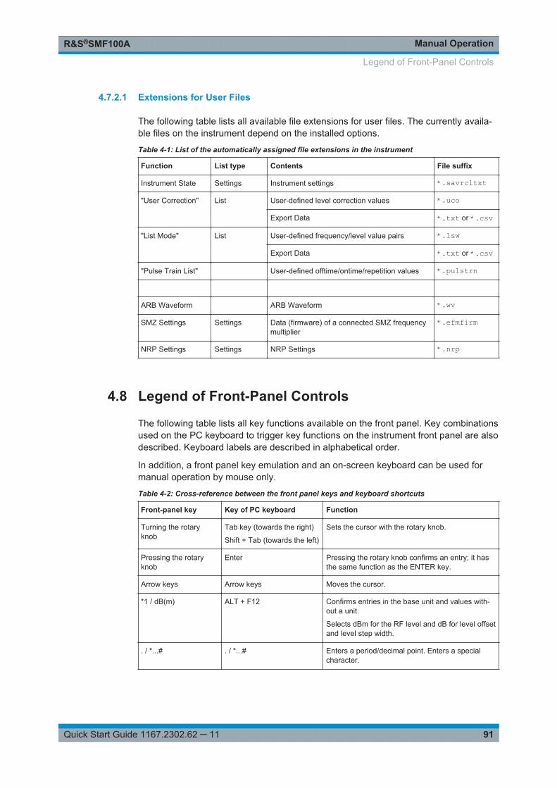
Manual OperationR&S®SMF100A
91Quick Start Guide 1167.2302.62 ─ 11
4.7.2.1 Extensions for User Files
The following table lists all available file extensions for user files. The currently availa-ble files on the instrument depend on the installed options.
Table 4-1: List of the automatically assigned file extensions in the instrument
Function List type Contents File suffix
Instrument State Settings Instrument settings *.savrcltxt
"User Correction" List User-defined level correction values *.uco
Export Data *.txt or *.csv
"List Mode" List User-defined frequency/level value pairs *.lsw
Export Data *.txt or *.csv
"Pulse Train List" User-defined offtime/ontime/repetition values *.pulstrn
ARB Waveform ARB Waveform *.wv
SMZ Settings Settings Data (firmware) of a connected SMZ frequencymultiplier
*.efmfirm
NRP Settings Settings NRP Settings *.nrp
4.8 Legend of Front-Panel Controls
The following table lists all key functions available on the front panel. Key combinationsused on the PC keyboard to trigger key functions on the instrument front panel are alsodescribed. Keyboard labels are described in alphabetical order.
In addition, a front panel key emulation and an on-screen keyboard can be used formanual operation by mouse only.
Table 4-2: Cross-reference between the front panel keys and keyboard shortcuts
Front-panel key Key of PC keyboard Function
Turning the rotaryknob
Tab key (towards the right)
Shift + Tab (towards the left)
Sets the cursor with the rotary knob.
Pressing the rotaryknob
Enter Pressing the rotary knob confirms an entry; it hasthe same function as the ENTER key.
Arrow keys Arrow keys Moves the cursor.
*1 / dB(m) ALT + F12 Confirms entries in the base unit and values with-out a unit.
Selects dBm for the RF level and dB for level offsetand level step width.
. / *...# . / *...# Enters a period/decimal point. Enters a specialcharacter.
Legend of Front-Panel Controls
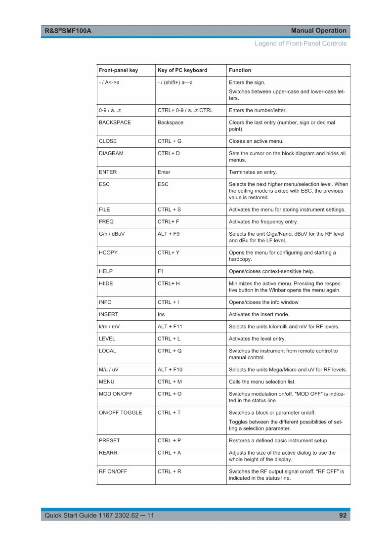
Manual OperationR&S®SMF100A
92Quick Start Guide 1167.2302.62 ─ 11
Front-panel key Key of PC keyboard Function
- / A<->a - / (shift+) a—z Enters the sign.
Switches between upper-case and lower-case let-ters.
0-9 / a...z CTRL+ 0-9 / a...z CTRL Enters the number/letter.
BACKSPACE Backspace Clears the last entry (number, sign or decimalpoint)
CLOSE CTRL + G Closes an active menu.
DIAGRAM CTRL+ D Sets the cursor on the block diagram and hides allmenus.
ENTER Enter Terminates an entry.
ESC ESC Selects the next higher menu/selection level. Whenthe editing mode is exited with ESC, the previousvalue is restored.
FILE CTRL + S Activates the menu for storing instrument settings.
FREQ CTRL+ F Activates the frequency entry.
G/n / dBuV ALT + F9 Selects the unit Giga/Nano, dBuV for the RF leveland dBu for the LF level.
HCOPY CTRL+ Y Opens the menu for configuring and starting ahardcopy.
HELP F1 Opens/closes context-sensitive help.
HIIDE CTRL+ H Minimizes the active menu. Pressing the respec-tive button in the Winbar opens the menu again.
INFO CTRL + I Opens/closes the info window
INSERT Ins Activates the insert mode.
k/m / mV ALT + F11 Selects the units kilo/milli and mV for RF levels.
LEVEL CTRL + L Activates the level entry.
LOCAL CTRL + Q Switches the instrument from remote control tomanual control.
M/u / uV ALT + F10 Selects the units Mega/Micro and uV for RF levels.
MENU CTRL + M Calls the menu selection list.
MOD ON/OFF CTRL + O Switches modulation on/off. "MOD OFF" is indica-ted in the status line.
ON/OFF TOGGLE CTRL + T Switches a block or parameter on/off.
Toggles between the different possibilities of set-ting a selection parameter.
PRESET CTRL + P Restores a defined basic instrument setup.
REARR. CTRL + A Adjusts the size of the active dialog to use thewhole height of the display.
RF ON/OFF CTRL + R Switches the RF output signal on/off. "RF OFF" isindicated in the status line.
Legend of Front-Panel Controls

Manual OperationR&S®SMF100A
93Quick Start Guide 1167.2302.62 ─ 11
Front-panel key Key of PC keyboard Function
SETUP CTRL + E Opens the setup menu for general instrument set-tings.
Softkeys CTRL + F1 – F8 Triggers the function assigned to the softkey.
STATUS CTRL + Indicates the instrument status.
WINBAR CTRL + W Toggles between the active menus.
4.8.1 Front Panel Key Emulation
The R&S SMF provides a front panel key emulation to enable execution of the frontpanel key functions by mouse e.g. for remote access. The emulation is called by a rightmouse click. The front panel key functions are executed by a mouse click on the asso-ciated button.
Legend of Front-Panel Controls

Manual OperationR&S®SMF100A
94Quick Start Guide 1167.2302.62 ─ 11
Legend of Front-Panel Controls

Hardware InterfacesR&S®SMF100A
95Quick Start Guide 1167.2302.62 ─ 11
AnnexA Hardware Interfaces
This section covers hardware related topics, like pin assignment of the GPIB bus inter-face.
The remote control interfaces are described in detailes in the Operating Manual, sec-tion "Remote Control Basics".
All other interfaces are described in Chapter 2.1, "Front Panel Tour", on page 11 andChapter 2.2, "Rear Panel Tour", on page 19.
For specifications refer to the data sheet.
A.1 GPIB Bus Interface
Pin assignment
Figure A-1: Pin assignment of GPIB bus interface
Bus lines
● Data bus with 8 lines D0 to D7:The transmission is bit-parallel and byte-serial in the ASCII/ISO code. D0 is theleast significant bit, D7 the most significant bit.
● Control bus with five lines:
GPIB Bus Interface

Hardware InterfacesR&S®SMF100A
96Quick Start Guide 1167.2302.62 ─ 11
IFC (Interface Clear): active LOW resets the interfaces of the instruments connec-ted to the default setting.ATN (Attention): active LOW signals the transmission of interface messages, inac-tive HIGH signals the transmission of device messages.SRQ (Service Request): active LOW enables the connected device to send a ser-vice request to the controller.REN (Remote Enable): active LOW permits switchover to remote control.EOI (End or Identify): has two functions in connection with ATN:– ATN=HIGH active LOW marks the end of data transmission.– ATN=LOW active LOW triggers a parallel poll.
● Handshake bus with three lines:DAV (Data Valid): active LOW signals a valid data byte on the data bus.NRFD (Not Ready For Data): active LOW signals that one of the connected devi-ces is not ready for data transfer.NDAC (Not Data Accepted): active LOW signals that the instrument connected isaccepting the data on the data bus.
Interface Functions
Instruments which can be controlled via GPIB bus can be equipped with different inter-face functions. The interface function for the R&S SMF are listed in the following table.
Table A-1: GPIB bus interface functions
Control character Interface function
SH1 Handshake source function (source handshake), full capability
AH1 Handshake sink function (acceptor handshake), full capability
L4 Listener function, full capability, de-addressed by MTA.
T6 Talker function, full capability, ability to respond to serial poll, dead-dressed by MLA
SR1 Service request function (Service Request), full capability
PP1 Parallel poll function, full capability
RL1 Remote/Local switch over function, full capability
DC1 Reset function (Device Clear), full capability
DT1 Trigger function (Device Trigger), full capability
GPIB Bus Interface

IndexR&S®SMF100A
97Quick Start Guide 1167.2302.62 ─ 11
Index
A
Abort button .......................................................................84Abort calculation ................................................................84AC supply ......................................................................... 20Access denied ................................................................... 76Application cards ................................................................. 8Application notes ................................................................. 8Architecture of the instrument ........................................... 53Arrow keys ........................................................................ 16ATN ................................................................................... 95Attention ............................................................................ 95Auto-negotiation
see Autonegotiation .................................................... 34Autonegotiation
Failure ......................................................................... 34
B
Brochure ..............................................................................8Browser settings
LXI .............................................................................. 44
C
Computer nameChanging .................................................................... 35use instead of IP address ........................................... 35
Connection to an external controller ................................. 36Connector
AUX I/O .......................................................................19BLANK ........................................................................ 21EFC .............................................................................21EXT 1 .................................................................... 17, 19EXT 2 .................................................................... 17, 19EXT ALC ............................................................... 18, 22GPIB ........................................................................... 20IEC/IEEE .....................................................................20LAN ............................................................................. 19LF ..........................................................................17, 22MARKER .................................................................... 21PULSE IN ................................................................... 22PULSE OUT ............................................................... 22REF IN ........................................................................ 21REF OUT .................................................................... 21RF ............................................................................... 18RF OUT ...................................................................... 21SENSOR ...............................................................17, 19STOP .......................................................................... 21SYNC .......................................................................... 22TRIGGER ................................................................... 21USB ............................................................................ 18USB type A ................................................................. 20USB type B ................................................................. 20USER 1 ....................................................................... 22USER 2 ....................................................................... 22USER 3 ....................................................................... 22V/GHz ......................................................................... 21VIDEO .........................................................................19X-AXIS ........................................................................ 22Z-AXIS ........................................................................ 22
Control bus ........................................................................ 95Controller, external ............................................................ 36
Cursor keys ....................................................................... 16
D
Data sheet ........................................................................... 8Data Valid ..........................................................................95DAV ................................................................................... 95Default instrument settings ................................................28DHCP ................................................................................ 34Display .............................................................................. 71Documentation overview ..................................................... 7
E
Electrostatic discharge ...................................................... 23EMI suppression ............................................................... 24EOI .................................................................................... 95Error messages ................................................................. 73ESD ................................................................................... 23
F
FailureNetwork connection .................................................... 34
Frequency display ............................................................. 71Front panel key emulation ................................................. 93Fuses ................................................................................ 26
G
Getting started ...................................................................53
H
Host namesee Computer name ................................................... 35
Hostnamesee Computer name ................................................... 35
I
IFC .................................................................................... 95INFO key ........................................................................... 73Input connector ..................................................... 17, 18, 21Interface
functions (GPIB bus) ...................................................96Interface Clear ...................................................................95IP address
Changing .................................................................... 34
K
KeyArrow key .................................................................... 17BACKSPACE .............................................................. 16CLOSE ........................................................................15Cursor key .................................................................. 17DIAGRAM ................................................................... 14ENTER ........................................................................16ESC ............................................................................ 14FILE ............................................................................ 14FREQ .......................................................................... 13HCOPY ....................................................................... 12HELP .......................................................................... 12

IndexR&S®SMF100A
98Quick Start Guide 1167.2302.62 ─ 11
HIDE ........................................................................... 15INFO ........................................................................... 12INSERT .......................................................................16LEVEL .........................................................................14LOCAL ........................................................................ 12MENU ......................................................................... 14MOD ON/OFF ............................................................. 14ON/OFF ...................................................................... 14PRESET ............................................................... 12, 28REARR ....................................................................... 15RF ON/OFF ................................................................ 13SETUP ........................................................................ 12TOGGLE ..................................................................... 14WINBAR ..................................................................... 15
Key combinations .............................................................. 91Keypad .............................................................................. 15
L
LANConfiguration .............................................................. 33
LAN connectionNot working ................................................................. 34
Level display ..................................................................... 71Linux ..................................................................................31Linux controller .................................................................. 38LXI
Browser interface ........................................................ 44Browser settings ......................................................... 44Configuration .............................................................. 43LAN configuration ....................................................... 46Ping .............................................................................48Remote trace (SCPI) .................................................. 51Web Control ................................................................ 49
M
Manual Remote Control .................................................... 36Menu structure
Access denied ............................................................ 76Header ........................................................................ 76Menu area ...................................................................76
N
Navigation keys ................................................................. 16NDAC ................................................................................ 95Network connection
Error ............................................................................ 34NRFD ................................................................................ 95
O
Online help .......................................................................... 7Working with ............................................................... 86
Online manual ..................................................................... 7Open source acknowledgment ............................................8Operating concept ............................................................. 53Operating manual ................................................................7Operating system .............................................................. 31Option
R&S SMF-B20 ............................................................ 19R&S SMF-B81 ................................................ 19, 21, 22R&S SMF-B83 ............................................................ 20R&S SMF-K3 ........................................................ 56, 57R&S SMF-K23 ...................................................... 22, 56R&S SMF-K27 ............................................................ 56
OSA .....................................................................................8Output connector .............................................17, 18, 19, 21
P
PingLXI .............................................................................. 48
Point-to-point connection .................................................. 33Preset ................................................................................ 28Preset instrument settings .................................................28
Q
Quick start guide ................................................................. 7
R
Rackmounting ................................................................... 26Release notes ..................................................................... 8Remote access ................................................................. 36Remote connection
Not working ................................................................. 34Remote trace
LXI .............................................................................. 51REN ...................................................................................95Reset instrument settings ..................................................28RF Frequency .................................................................. 56Rotary knob ....................................................................... 16
S
Safety instructions ............................................................... 7SCPI remote trace
LXI .............................................................................. 51Service manual ................................................................... 7Setting not possible ........................................................... 76Setting parameters ............................................................ 77SRQ .................................................................................. 95Standby mode ................................................................... 12
U
Ultr@VNC ......................................................................... 38Units
Input ............................................................................ 15UNIX controller .................................................................. 38
V
VNC connection ................................................................ 38
W
Warnings ........................................................................... 73Web Control
LXI .............................................................................. 49White papers ....................................................................... 8