Embed Size (px)
Citation preview
R&S®NRP2Power MeterUser Manual
User
Man
ual
1173.9140.02 ─ 07(;×éX2)
Test
& Me
asur
emen
t
This document describes the R&S®NRP2 and its options.● R&S®NRP-B1/-B7, Sensor Check Source
● R&S®NRP-B2, Second Sensor Input B
● R&S®NRP-B5, 3rd and 4th Sensor Input C and D
● R&S®NRP-B6, Rear Panel Sensor Input A and B
© 2015 Rohde & Schwarz GmbH & Co. KGMühldorfstr. 15, 81671 München, GermanyPhone: +49 89 41 29 - 0Fax: +49 89 41 29 12 164Email: [email protected]: www.rohde-schwarz.comSubject to change – Data without tolerance limits is not binding.R&S® is a registered trademark of Rohde & Schwarz GmbH & Co. KG.Trade names are trademarks of the owners.
The following abbreviations are used throughout this manual: R&S®NRP2 is abbreviated as R&S NRP2, and the R&S ®NRP-ZxxPower Sensors are abbreviated as R&S NRP-Zxx.
1171.0000.42 - 08 Page 1
Basic Safety Instructions
Always read through and comply with the following safety instructions!
All plants and locations of the Rohde & Schwarz group of companies make every effort to keep the safety
standards of our products up to date and to offer our customers the highest possible degree of safety. Our
products and the auxiliary equipment they require are designed, built and tested in accordance with the
safety standards that apply in each case. Compliance with these standards is continuously monitored by
our quality assurance system. The product described here has been designed, built and tested in
accordance with the EC Certificate of Conformity and has left the manufacturer’s plant in a condition fully
complying with safety standards. To maintain this condition and to ensure safe operation, you must
observe all instructions and warnings provided in this manual. If you have any questions regarding these
safety instructions, the Rohde & Schwarz group of companies will be happy to answer them.
Furthermore, it is your responsibility to use the product in an appropriate manner. This product is designed
for use solely in industrial and laboratory environments or, if expressly permitted, also in the field and must
not be used in any way that may cause personal injury or property damage. You are responsible if the
product is used for any purpose other than its designated purpose or in disregard of the manufacturer's
instructions. The manufacturer shall assume no responsibility for such use of the product.
The product is used for its designated purpose if it is used in accordance with its product documentation
and within its performance limits (see data sheet, documentation, the following safety instructions). Using
the product requires technical skills and, in some cases, a basic knowledge of English. It is therefore
essential that only skilled and specialized staff or thoroughly trained personnel with the required skills be
allowed to use the product. If personal safety gear is required for using Rohde & Schwarz products, this
will be indicated at the appropriate place in the product documentation. Keep the basic safety instructions
and the product documentation in a safe place and pass them on to the subsequent users.
Observing the safety instructions will help prevent personal injury or damage of any kind caused by
dangerous situations. Therefore, carefully read through and adhere to the following safety instructions
before and when using the product. It is also absolutely essential to observe the additional safety
instructions on personal safety, for example, that appear in relevant parts of the product documentation. In
these safety instructions, the word "product" refers to all merchandise sold and distributed by the Rohde &
Schwarz group of companies, including instruments, systems and all accessories. For product-specific
information, see the data sheet and the product documentation.
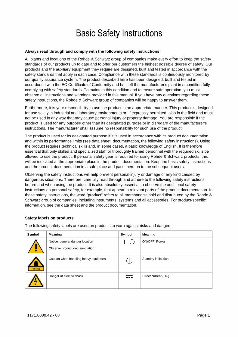
Safety labels on products
The following safety labels are used on products to warn against risks and dangers.
Symbol Meaning Symbol Meaning
Notice, general danger location
Observe product documentation
ON/OFF Power
Caution when handling heavy equipment
Standby indication
Danger of electric shock Direct current (DC)
Basic Safety Instructions
1171.0000.42 - 08 Page 2
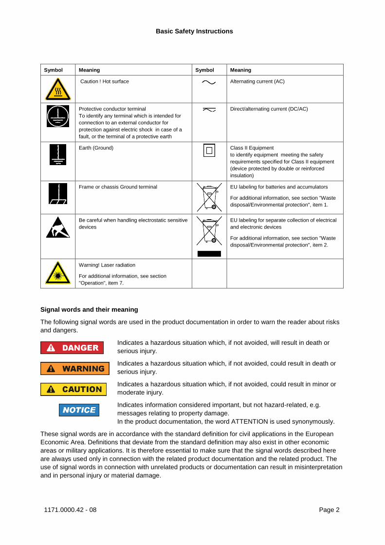
Symbol Meaning Symbol Meaning
Caution ! Hot surface Alternating current (AC)
Protective conductor terminal
To identify any terminal which is intended for
connection to an external conductor for
protection against electric shock in case of a
fault, or the terminal of a protective earth
Direct/alternating current (DC/AC)
Earth (Ground)
Class II Equipment
to identify equipment meeting the safety
requirements specified for Class II equipment
(device protected by double or reinforced
insulation)
Frame or chassis Ground terminal
EU labeling for batteries and accumulators
For additional information, see section "Waste
disposal/Environmental protection", item 1.
Be careful when handling electrostatic sensitive
devices
EU labeling for separate collection of electrical
and electronic devices
For additional information, see section "Waste
disposal/Environmental protection", item 2.
Warning! Laser radiation
For additional information, see section
"Operation", item 7.
Signal words and their meaning
The following signal words are used in the product documentation in order to warn the reader about risks
and dangers.
Indicates a hazardous situation which, if not avoided, will result in death or
serious injury.
Indicates a hazardous situation which, if not avoided, could result in death or
serious injury.
Indicates a hazardous situation which, if not avoided, could result in minor or
moderate injury.
Indicates information considered important, but not hazard-related, e.g.
messages relating to property damage.
In the product documentation, the word ATTENTION is used synonymously.
These signal words are in accordance with the standard definition for civil applications in the European
Economic Area. Definitions that deviate from the standard definition may also exist in other economic
areas or military applications. It is therefore essential to make sure that the signal words described here
are always used only in connection with the related product documentation and the related product. The
use of signal words in connection with unrelated products or documentation can result in misinterpretation
and in personal injury or material damage.
Basic Safety Instructions
1171.0000.42 - 08 Page 3
Operating states and operating positions
The product may be operated only under the operating conditions and in the positions specified by the
manufacturer, without the product's ventilation being obstructed. If the manufacturer's specifications are
not observed, this can result in electric shock, fire and/or serious personal injury or death. Applicable local
or national safety regulations and rules for the prevention of accidents must be observed in all work
performed.
1. Unless otherwise specified, the following requirements apply to Rohde & Schwarz products:
predefined operating position is always with the housing floor facing down, IP protection 2X, use only
indoors, max. operating altitude 2000 m above sea level, max. transport altitude 4500 m above sea
level. A tolerance of ±10 % shall apply to the nominal voltage and ±5 % to the nominal frequency,
overvoltage category 2, pollution degree 2.
2. Do not place the product on surfaces, vehicles, cabinets or tables that for reasons of weight or stability
are unsuitable for this purpose. Always follow the manufacturer's installation instructions when
installing the product and fastening it to objects or structures (e.g. walls and shelves). An installation
that is not carried out as described in the product documentation could result in personal injury or
even death.
3. Do not place the product on heat-generating devices such as radiators or fan heaters. The ambient
temperature must not exceed the maximum temperature specified in the product documentation or in
the data sheet. Product overheating can cause electric shock, fire and/or serious personal injury or
even death.
Electrical safety
If the information on electrical safety is not observed either at all or to the extent necessary, electric shock,
fire and/or serious personal injury or death may occur.
1. Prior to switching on the product, always ensure that the nominal voltage setting on the product
matches the nominal voltage of the mains-supply network. If a different voltage is to be set, the power
fuse of the product may have to be changed accordingly.
2. In the case of products of safety class I with movable power cord and connector, operation is
permitted only on sockets with a protective conductor contact and protective conductor.
3. Intentionally breaking the protective conductor either in the feed line or in the product itself is not
permitted. Doing so can result in the danger of an electric shock from the product. If extension cords
or connector strips are implemented, they must be checked on a regular basis to ensure that they are
safe to use.
4. If there is no power switch for disconnecting the product from the mains, or if the power switch is not
suitable for this purpose, use the plug of the connecting cable to disconnect the product from the
mains. In such cases, always ensure that the power plug is easily reachable and accessible at all
times. For example, if the power plug is the disconnecting device, the length of the connecting cable
must not exceed 3 m. Functional or electronic switches are not suitable for providing disconnection
from the AC supply network. If products without power switches are integrated into racks or systems,
the disconnecting device must be provided at the system level.
5. Never use the product if the power cable is damaged. Check the power cables on a regular basis to
ensure that they are in proper operating condition. By taking appropriate safety measures and
carefully laying the power cable, ensure that the cable cannot be damaged and that no one can be
hurt by, for example, tripping over the cable or suffering an electric shock.
Basic Safety Instructions
1171.0000.42 - 08 Page 4
6. The product may be operated only from TN/TT supply networks fuse-protected with max. 16 A (higher
fuse only after consulting with the Rohde & Schwarz group of companies).
7. Do not insert the plug into sockets that are dusty or dirty. Insert the plug firmly and all the way into the
socket provided for this purpose. Otherwise, sparks that result in fire and/or injuries may occur.
8. Do not overload any sockets, extension cords or connector strips; doing so can cause fire or electric
shocks.
9. For measurements in circuits with voltages Vrms > 30 V, suitable measures (e.g. appropriate
measuring equipment, fuse protection, current limiting, electrical separation, insulation) should be
taken to avoid any hazards.
10. Ensure that the connections with information technology equipment, e.g. PCs or other industrial
computers, comply with the IEC 60950-1 / EN 60950-1 or IEC 61010-1 / EN 61010-1 standards that
apply in each case.
11. Unless expressly permitted, never remove the cover or any part of the housing while the product is in
operation. Doing so will expose circuits and components and can lead to injuries, fire or damage to the
product.
12. If a product is to be permanently installed, the connection between the protective conductor terminal
on site and the product's protective conductor must be made first before any other connection is
made. The product may be installed and connected only by a licensed electrician.
13. For permanently installed equipment without built-in fuses, circuit breakers or similar protective
devices, the supply circuit must be fuse-protected in such a way that anyone who has access to the
product, as well as the product itself, is adequately protected from injury or damage.
14. Use suitable overvoltage protection to ensure that no overvoltage (such as that caused by a bolt of
lightning) can reach the product. Otherwise, the person operating the product will be exposed to the
danger of an electric shock.
15. Any object that is not designed to be placed in the openings of the housing must not be used for this
purpose. Doing so can cause short circuits inside the product and/or electric shocks, fire or injuries.
16. Unless specified otherwise, products are not liquid-proof (see also section "Operating states and
operating positions", item 1). Therefore, the equipment must be protected against penetration by
liquids. If the necessary precautions are not taken, the user may suffer electric shock or the product
itself may be damaged, which can also lead to personal injury.
17. Never use the product under conditions in which condensation has formed or can form in or on the
product, e.g. if the product has been moved from a cold to a warm environment. Penetration by water
increases the risk of electric shock.
18. Prior to cleaning the product, disconnect it completely from the power supply (e.g. AC supply network
or battery). Use a soft, non-linting cloth to clean the product. Never use chemical cleaning agents such
as alcohol, acetone or diluents for cellulose lacquers.
Operation
1. Operating the products requires special training and intense concentration. Make sure that persons
who use the products are physically, mentally and emotionally fit enough to do so; otherwise, injuries
or material damage may occur. It is the responsibility of the employer/operator to select suitable
personnel for operating the products.
Basic Safety Instructions
1171.0000.42 - 08 Page 5
2. Before you move or transport the product, read and observe the section titled "Transport".
3. As with all industrially manufactured goods, the use of substances that induce an allergic reaction
(allergens) such as nickel cannot be generally excluded. If you develop an allergic reaction (such as a
skin rash, frequent sneezing, red eyes or respiratory difficulties) when using a Rohde & Schwarz
product, consult a physician immediately to determine the cause and to prevent health problems or
stress.
4. Before you start processing the product mechanically and/or thermally, or before you take it apart, be
sure to read and pay special attention to the section titled "Waste disposal/Environmental protection",
item 1.
5. Depending on the function, certain products such as RF radio equipment can produce an elevated
level of electromagnetic radiation. Considering that unborn babies require increased protection,
pregnant women must be protected by appropriate measures. Persons with pacemakers may also be
exposed to risks from electromagnetic radiation. The employer/operator must evaluate workplaces
where there is a special risk of exposure to radiation and, if necessary, take measures to avert the
potential danger.
6. Should a fire occur, the product may release hazardous substances (gases, fluids, etc.) that can
cause health problems. Therefore, suitable measures must be taken, e.g. protective masks and
protective clothing must be worn.
7. Laser products are given warning labels that are standardized according to their laser class. Lasers
can cause biological harm due to the properties of their radiation and due to their extremely
concentrated electromagnetic power. If a laser product (e.g. a CD/DVD drive) is integrated into a
Rohde & Schwarz product, absolutely no other settings or functions may be used as described in the
product documentation. The objective is to prevent personal injury (e.g. due to laser beams).
8. EMC classes (in line with EN 55011/CISPR 11, and analogously with EN 55022/CISPR 22,
EN 55032/CISPR 32)
Class A equipment:
Equipment suitable for use in all environments except residential environments and environments
that are directly connected to a low-voltage supply network that supplies residential buildings
Note: Class A equipment is intended for use in an industrial environment. This equipment may
cause radio disturbances in residential environments, due to possible conducted as well as
radiated disturbances. In this case, the operator may be required to take appropriate measures to
eliminate these disturbances.
Class B equipment:
Equipment suitable for use in residential environments and environments that are directly
connected to a low-voltage supply network that supplies residential buildings
Repair and service
1. The product may be opened only by authorized, specially trained personnel. Before any work is
performed on the product or before the product is opened, it must be disconnected from the AC supply
network. Otherwise, personnel will be exposed to the risk of an electric shock.
Basic Safety Instructions
1171.0000.42 - 08 Page 6
2. Adjustments, replacement of parts, maintenance and repair may be performed only by electrical
experts authorized by Rohde & Schwarz. Only original parts may be used for replacing parts relevant
to safety (e.g. power switches, power transformers, fuses). A safety test must always be performed
after parts relevant to safety have been replaced (visual inspection, protective conductor test,
insulation resistance measurement, leakage current measurement, functional test). This helps ensure
the continued safety of the product.
Batteries and rechargeable batteries/cells
If the information regarding batteries and rechargeable batteries/cells is not observed either at all or to the
extent necessary, product users may be exposed to the risk of explosions, fire and/or serious personal
injury, and, in some cases, death. Batteries and rechargeable batteries with alkaline electrolytes (e.g.
lithium cells) must be handled in accordance with the EN 62133 standard.
1. Cells must not be taken apart or crushed.
2. Cells or batteries must not be exposed to heat or fire. Storage in direct sunlight must be avoided.
Keep cells and batteries clean and dry. Clean soiled connectors using a dry, clean cloth.
3. Cells or batteries must not be short-circuited. Cells or batteries must not be stored in a box or in a
drawer where they can short-circuit each other, or where they can be short-circuited by other
conductive materials. Cells and batteries must not be removed from their original packaging until they
are ready to be used.
4. Cells and batteries must not be exposed to any mechanical shocks that are stronger than permitted.
5. If a cell develops a leak, the fluid must not be allowed to come into contact with the skin or eyes. If
contact occurs, wash the affected area with plenty of water and seek medical aid.
6. Improperly replacing or charging cells or batteries that contain alkaline electrolytes (e.g. lithium cells)
can cause explosions. Replace cells or batteries only with the matching Rohde & Schwarz type (see
parts list) in order to ensure the safety of the product.
7. Cells and batteries must be recycled and kept separate from residual waste. Rechargeable batteries
and normal batteries that contain lead, mercury or cadmium are hazardous waste. Observe the
national regulations regarding waste disposal and recycling.
Transport
1. The product may be very heavy. Therefore, the product must be handled with care. In some cases,
the user may require a suitable means of lifting or moving the product (e.g. with a lift-truck) to avoid
back or other physical injuries.
2. Handles on the products are designed exclusively to enable personnel to transport the product. It is
therefore not permissible to use handles to fasten the product to or on transport equipment such as
cranes, fork lifts, wagons, etc. The user is responsible for securely fastening the products to or on the
means of transport or lifting. Observe the safety regulations of the manufacturer of the means of
transport or lifting. Noncompliance can result in personal injury or material damage.
3. If you use the product in a vehicle, it is the sole responsibility of the driver to drive the vehicle safely
and properly. The manufacturer assumes no responsibility for accidents or collisions. Never use the
product in a moving vehicle if doing so could distract the driver of the vehicle. Adequately secure the
product in the vehicle to prevent injuries or other damage in the event of an accident.
Instrucciones de seguridad elementales
1171.0000.42 - 08 Page 7
Waste disposal/Environmental protection
1. Specially marked equipment has a battery or accumulator that must not be disposed of with unsorted
municipal waste, but must be collected separately. It may only be disposed of at a suitable collection
point or via a Rohde & Schwarz customer service center.
2. Waste electrical and electronic equipment must not be disposed of with unsorted municipal waste, but
must be collected separately.
Rohde & Schwarz GmbH & Co. KG has developed a disposal concept and takes full responsibility for
take-back obligations and disposal obligations for manufacturers within the EU. Contact your
Rohde & Schwarz customer service center for environmentally responsible disposal of the product.
3. If products or their components are mechanically and/or thermally processed in a manner that goes
beyond their intended use, hazardous substances (heavy-metal dust such as lead, beryllium, nickel)
may be released. For this reason, the product may only be disassembled by specially trained
personnel. Improper disassembly may be hazardous to your health. National waste disposal
regulations must be observed.
4. If handling the product releases hazardous substances or fuels that must be disposed of in a special
way, e.g. coolants or engine oils that must be replenished regularly, the safety instructions of the
manufacturer of the hazardous substances or fuels and the applicable regional waste disposal
regulations must be observed. Also observe the relevant safety instructions in the product
documentation. The improper disposal of hazardous substances or fuels can cause health problems
and lead to environmental damage.
For additional information about environmental protection, visit the Rohde & Schwarz website.
Instrucciones de seguridad elementales
¡Es imprescindible leer y cumplir las siguientes instrucciones e informaciones de seguridad!
El principio del grupo de empresas Rohde & Schwarz consiste en tener nuestros productos siempre al día
con los estándares de seguridad y de ofrecer a nuestros clientes el máximo grado de seguridad. Nuestros
productos y todos los equipos adicionales son siempre fabricados y examinados según las normas de
seguridad vigentes. Nuestro sistema de garantía de calidad controla constantemente que sean cumplidas
estas normas. El presente producto ha sido fabricado y examinado según el certificado de conformidad
de la UE y ha salido de nuestra planta en estado impecable según los estándares técnicos de seguridad.
Para poder preservar este estado y garantizar un funcionamiento libre de peligros, el usuario deberá
atenerse a todas las indicaciones, informaciones de seguridad y notas de alerta. El grupo de empresas
Rohde & Schwarz está siempre a su disposición en caso de que tengan preguntas referentes a estas
informaciones de seguridad.
Además queda en la responsabilidad del usuario utilizar el producto en la forma debida. Este producto
está destinado exclusivamente al uso en la industria y el laboratorio o, si ha sido expresamente
autorizado, para aplicaciones de campo y de ninguna manera deberá ser utilizado de modo que alguna
persona/cosa pueda sufrir daño. El uso del producto fuera de sus fines definidos o sin tener en cuenta las
instrucciones del fabricante queda en la responsabilidad del usuario. El fabricante no se hace en ninguna
forma responsable de consecuencias a causa del mal uso del producto.
Instrucciones de seguridad elementales
1171.0000.42 - 08 Page 8
Se parte del uso correcto del producto para los fines definidos si el producto es utilizado conforme a las
indicaciones de la correspondiente documentación del producto y dentro del margen de rendimiento
definido (ver hoja de datos, documentación, informaciones de seguridad que siguen). El uso del producto
hace necesarios conocimientos técnicos y ciertos conocimientos del idioma inglés. Por eso se debe tener
en cuenta que el producto solo pueda ser operado por personal especializado o personas instruidas en
profundidad con las capacidades correspondientes. Si fuera necesaria indumentaria de seguridad para el
uso de productos de Rohde & Schwarz, encontraría la información debida en la documentación del
producto en el capítulo correspondiente. Guarde bien las informaciones de seguridad elementales, así
como la documentación del producto, y entréguelas a usuarios posteriores.
Tener en cuenta las informaciones de seguridad sirve para evitar en lo posible lesiones o daños por
peligros de toda clase. Por eso es imprescindible leer detalladamente y comprender por completo las
siguientes informaciones de seguridad antes de usar el producto, y respetarlas durante el uso del
producto. Deberán tenerse en cuenta todas las demás informaciones de seguridad, como p. ej. las
referentes a la protección de personas, que encontrarán en el capítulo correspondiente de la
documentación del producto y que también son de obligado cumplimiento. En las presentes
informaciones de seguridad se recogen todos los objetos que distribuye el grupo de empresas
Rohde & Schwarz bajo la denominación de "producto", entre ellos también aparatos, instalaciones así
como toda clase de accesorios. Los datos específicos del producto figuran en la hoja de datos y en la
documentación del producto.
Señalización de seguridad de los productos
Las siguientes señales de seguridad se utilizan en los productos para advertir sobre riesgos y peligros.
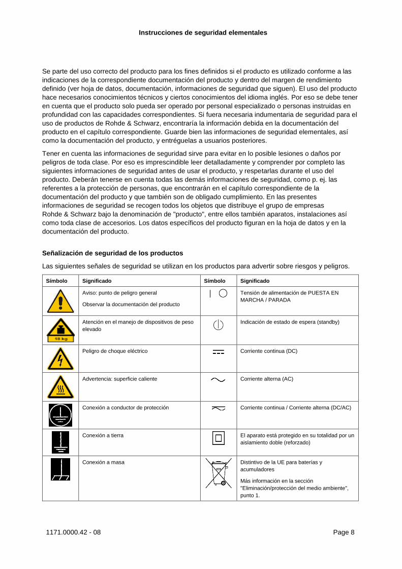
Símbolo Significado Símbolo Significado
Aviso: punto de peligro general
Observar la documentación del producto
Tensión de alimentación de PUESTA EN
MARCHA / PARADA
Atención en el manejo de dispositivos de peso
elevado
Indicación de estado de espera (standby)
Peligro de choque eléctrico Corriente continua (DC)
Advertencia: superficie caliente Corriente alterna (AC)
Conexión a conductor de protección Corriente continua / Corriente alterna (DC/AC)
Conexión a tierra
El aparato está protegido en su totalidad por un
aislamiento doble (reforzado)
Conexión a masa
Distintivo de la UE para baterías y
acumuladores
Más información en la sección
"Eliminación/protección del medio ambiente",
punto 1.
Instrucciones de seguridad elementales
1171.0000.42 - 08 Page 9
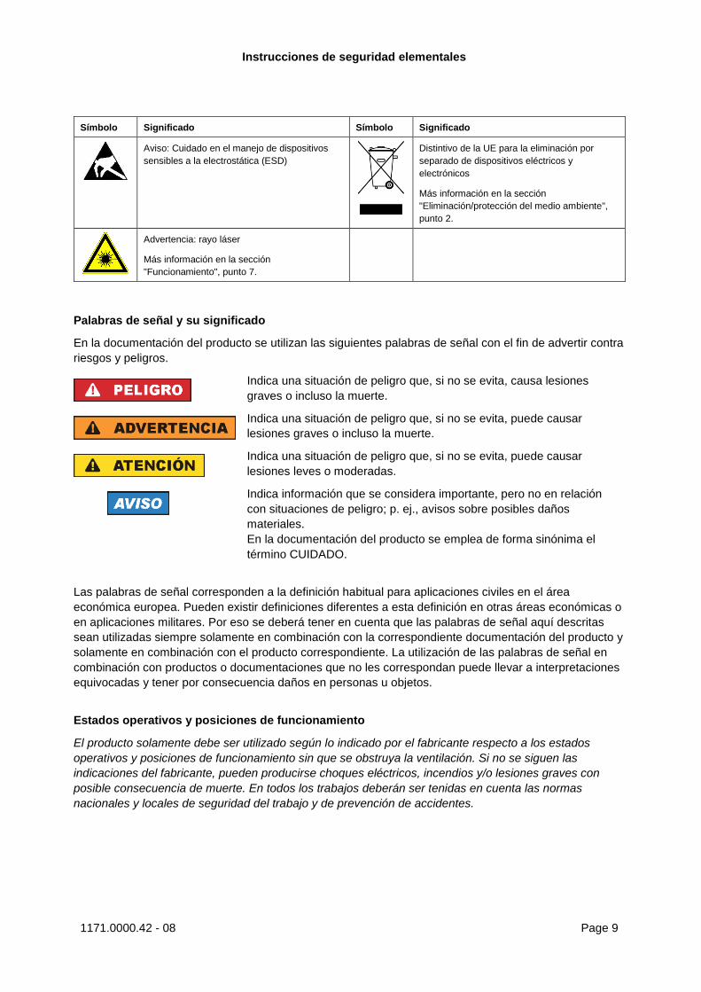
Símbolo Significado Símbolo Significado
Aviso: Cuidado en el manejo de dispositivos
sensibles a la electrostática (ESD)
Distintivo de la UE para la eliminación por
separado de dispositivos eléctricos y
electrónicos
Más información en la sección
"Eliminación/protección del medio ambiente",
punto 2.
Advertencia: rayo láser
Más información en la sección
"Funcionamiento", punto 7.
Palabras de señal y su significado
En la documentación del producto se utilizan las siguientes palabras de señal con el fin de advertir contra
riesgos y peligros.
Indica una situación de peligro que, si no se evita, causa lesiones
graves o incluso la muerte.
Indica una situación de peligro que, si no se evita, puede causar
lesiones graves o incluso la muerte.
Indica una situación de peligro que, si no se evita, puede causar
lesiones leves o moderadas.
Indica información que se considera importante, pero no en relación
con situaciones de peligro; p. ej., avisos sobre posibles daños
materiales.
En la documentación del producto se emplea de forma sinónima el
término CUIDADO.
Las palabras de señal corresponden a la definición habitual para aplicaciones civiles en el área
económica europea. Pueden existir definiciones diferentes a esta definición en otras áreas económicas o
en aplicaciones militares. Por eso se deberá tener en cuenta que las palabras de señal aquí descritas
sean utilizadas siempre solamente en combinación con la correspondiente documentación del producto y
solamente en combinación con el producto correspondiente. La utilización de las palabras de señal en
combinación con productos o documentaciones que no les correspondan puede llevar a interpretaciones
equivocadas y tener por consecuencia daños en personas u objetos.
Estados operativos y posiciones de funcionamiento
El producto solamente debe ser utilizado según lo indicado por el fabricante respecto a los estados
operativos y posiciones de funcionamiento sin que se obstruya la ventilación. Si no se siguen las
indicaciones del fabricante, pueden producirse choques eléctricos, incendios y/o lesiones graves con
posible consecuencia de muerte. En todos los trabajos deberán ser tenidas en cuenta las normas
nacionales y locales de seguridad del trabajo y de prevención de accidentes.
Instrucciones de seguridad elementales
1171.0000.42 - 08 Page 10
1. Si no se convino de otra manera, es para los productos Rohde & Schwarz válido lo que sigue:
como posición de funcionamiento se define por principio la posición con el suelo de la caja para
abajo, modo de protección IP 2X, uso solamente en estancias interiores, utilización hasta 2000 m
sobre el nivel del mar, transporte hasta 4500 m sobre el nivel del mar. Se aplicará una tolerancia de
±10 % sobre el voltaje nominal y de ±5 % sobre la frecuencia nominal. Categoría de sobrecarga
eléctrica 2, índice de suciedad 2.
2. No sitúe el producto encima de superficies, vehículos, estantes o mesas, que por sus características
de peso o de estabilidad no sean aptos para él. Siga siempre las instrucciones de instalación del
fabricante cuando instale y asegure el producto en objetos o estructuras (p. ej. paredes y estantes). Si
se realiza la instalación de modo distinto al indicado en la documentación del producto, se pueden
causar lesiones o, en determinadas circunstancias, incluso la muerte.
3. No ponga el producto sobre aparatos que generen calor (p. ej. radiadores o calefactores). La
temperatura ambiente no debe superar la temperatura máxima especificada en la documentación del
producto o en la hoja de datos. En caso de sobrecalentamiento del producto, pueden producirse
choques eléctricos, incendios y/o lesiones graves con posible consecuencia de muerte.
Seguridad eléctrica
Si no se siguen (o se siguen de modo insuficiente) las indicaciones del fabricante en cuanto a seguridad
eléctrica, pueden producirse choques eléctricos, incendios y/o lesiones graves con posible consecuencia
de muerte.
1. Antes de la puesta en marcha del producto se deberá comprobar siempre que la tensión
preseleccionada en el producto coincida con la de la red de alimentación eléctrica. Si es necesario
modificar el ajuste de tensión, también se deberán cambiar en caso dado los fusibles
correspondientes del producto.
2. Los productos de la clase de protección I con alimentación móvil y enchufe individual solamente
podrán enchufarse a tomas de corriente con contacto de seguridad y con conductor de protección
conectado.
3. Queda prohibida la interrupción intencionada del conductor de protección, tanto en la toma de
corriente como en el mismo producto. La interrupción puede tener como consecuencia el riesgo de
que el producto sea fuente de choques eléctricos. Si se utilizan cables alargadores o regletas de
enchufe, deberá garantizarse la realización de un examen regular de los mismos en cuanto a su
estado técnico de seguridad.
4. Si el producto no está equipado con un interruptor para desconectarlo de la red, o bien si el
interruptor existente no resulta apropiado para la desconexión de la red, el enchufe del cable de
conexión se deberá considerar como un dispositivo de desconexión.
El dispositivo de desconexión se debe poder alcanzar fácilmente y debe estar siempre bien accesible.
Si, p. ej., el enchufe de conexión a la red es el dispositivo de desconexión, la longitud del cable de
conexión no debe superar 3 m).
Los interruptores selectores o electrónicos no son aptos para el corte de la red eléctrica. Si se
integran productos sin interruptor en bastidores o instalaciones, se deberá colocar el interruptor en el
nivel de la instalación.
5. No utilice nunca el producto si está dañado el cable de conexión a red. Compruebe regularmente el
correcto estado de los cables de conexión a red. Asegúrese, mediante las medidas de protección y
de instalación adecuadas, de que el cable de conexión a red no pueda ser dañado o de que nadie
pueda ser dañado por él, p. ej. al tropezar o por un choque eléctrico.
Instrucciones de seguridad elementales
1171.0000.42 - 08 Page 11
6. Solamente está permitido el funcionamiento en redes de alimentación TN/TT aseguradas con fusibles
de 16 A como máximo (utilización de fusibles de mayor amperaje solo previa consulta con el grupo de
empresas Rohde & Schwarz).
7. Nunca conecte el enchufe en tomas de corriente sucias o llenas de polvo. Introduzca el enchufe por
completo y fuertemente en la toma de corriente. La no observación de estas medidas puede provocar
chispas, fuego y/o lesiones.
8. No sobrecargue las tomas de corriente, los cables alargadores o las regletas de enchufe ya que esto
podría causar fuego o choques eléctricos.
9. En las mediciones en circuitos de corriente con una tensión Ueff > 30 V se deberán tomar las medidas
apropiadas para impedir cualquier peligro (p. ej. medios de medición adecuados, seguros, limitación
de tensión, corte protector, aislamiento etc.).
10. Para la conexión con dispositivos informáticos como un PC o un ordenador industrial, debe
comprobarse que éstos cumplan los estándares IEC60950-1/EN60950-1 o IEC61010-1/EN 61010-1
válidos en cada caso.
11. A menos que esté permitido expresamente, no retire nunca la tapa ni componentes de la carcasa
mientras el producto esté en servicio. Esto pone a descubierto los cables y componentes eléctricos y
puede causar lesiones, fuego o daños en el producto.
12. Si un producto se instala en un lugar fijo, se deberá primero conectar el conductor de protección fijo
con el conductor de protección del producto antes de hacer cualquier otra conexión. La instalación y
la conexión deberán ser efectuadas por un electricista especializado.
13. En el caso de dispositivos fijos que no estén provistos de fusibles, interruptor automático ni otros
mecanismos de seguridad similares, el circuito de alimentación debe estar protegido de modo que
todas las personas que puedan acceder al producto, así como el producto mismo, estén a salvo de
posibles daños.
14. Todo producto debe estar protegido contra sobretensión (debida p. ej. a una caída del rayo) mediante
los correspondientes sistemas de protección. Si no, el personal que lo utilice quedará expuesto al
peligro de choque eléctrico.
15. No debe introducirse en los orificios de la caja del aparato ningún objeto que no esté destinado a ello.
Esto puede producir cortocircuitos en el producto y/o puede causar choques eléctricos, fuego o
lesiones.
16. Salvo indicación contraria, los productos no están impermeabilizados (ver también el capítulo
"Estados operativos y posiciones de funcionamiento", punto 1). Por eso es necesario tomar las
medidas necesarias para evitar la entrada de líquidos. En caso contrario, existe peligro de choque
eléctrico para el usuario o de daños en el producto, que también pueden redundar en peligro para las
personas.
17. No utilice el producto en condiciones en las que pueda producirse o ya se hayan producido
condensaciones sobre el producto o en el interior de éste, como p. ej. al desplazarlo de un lugar frío a
otro caliente. La entrada de agua aumenta el riesgo de choque eléctrico.
18. Antes de la limpieza, desconecte por completo el producto de la alimentación de tensión (p. ej. red de
alimentación o batería). Realice la limpieza de los aparatos con un paño suave, que no se deshilache.
No utilice bajo ningún concepto productos de limpieza químicos como alcohol, acetona o diluyentes
para lacas nitrocelulósicas.

Instrucciones de seguridad elementales
1171.0000.42 - 08 Page 12
Funcionamiento
1. El uso del producto requiere instrucciones especiales y una alta concentración durante el manejo.
Debe asegurarse que las personas que manejen el producto estén a la altura de los requerimientos
necesarios en cuanto a aptitudes físicas, psíquicas y emocionales, ya que de otra manera no se
pueden excluir lesiones o daños de objetos. El empresario u operador es responsable de seleccionar
el personal usuario apto para el manejo del producto.
2. Antes de desplazar o transportar el producto, lea y tenga en cuenta el capítulo "Transporte".
3. Como con todo producto de fabricación industrial no puede quedar excluida en general la posibilidad
de que se produzcan alergias provocadas por algunos materiales empleados ―los llamados
alérgenos (p. ej. el níquel)―. Si durante el manejo de productos Rohde & Schwarz se producen
reacciones alérgicas, como p. ej. irritaciones cutáneas, estornudos continuos, enrojecimiento de la
conjuntiva o dificultades respiratorias, debe avisarse inmediatamente a un médico para investigar las
causas y evitar cualquier molestia o daño a la salud.
4. Antes de la manipulación mecánica y/o térmica o el desmontaje del producto, debe tenerse en cuenta
imprescindiblemente el capítulo "Eliminación/protección del medio ambiente", punto 1.
5. Ciertos productos, como p. ej. las instalaciones de radiocomunicación RF, pueden a causa de su
función natural, emitir una radiación electromagnética aumentada. Deben tomarse todas las medidas
necesarias para la protección de las mujeres embarazadas. También las personas con marcapasos
pueden correr peligro a causa de la radiación electromagnética. El empresario/operador tiene la
obligación de evaluar y señalizar las áreas de trabajo en las que exista un riesgo elevado de
exposición a radiaciones.
6. Tenga en cuenta que en caso de incendio pueden desprenderse del producto sustancias tóxicas
(gases, líquidos etc.) que pueden generar daños a la salud. Por eso, en caso de incendio deben
usarse medidas adecuadas, como p. ej. máscaras antigás e indumentaria de protección.
7. Los productos con láser están provistos de indicaciones de advertencia normalizadas en función de la
clase de láser del que se trate. Los rayos láser pueden provocar daños de tipo biológico a causa de
las propiedades de su radiación y debido a su concentración extrema de potencia electromagnética.
En caso de que un producto Rohde & Schwarz contenga un producto láser (p. ej. un lector de
CD/DVD), no debe usarse ninguna otra configuración o función aparte de las descritas en la
documentación del producto, a fin de evitar lesiones (p. ej. debidas a irradiación láser).
8. Clases de compatibilidad electromagnética (conforme a EN 55011 / CISPR 11; y en analogía con EN
55022 / CISPR 22, EN 55032 / CISPR 32)
Aparato de clase A:
Aparato adecuado para su uso en todos los entornos excepto en los residenciales y en aquellos
conectados directamente a una red de distribución de baja tensión que suministra corriente a
edificios residenciales.
Nota: Los aparatos de clase A están destinados al uso en entornos industriales. Estos aparatos
pueden causar perturbaciones radioeléctricas en entornos residenciales debido a posibles
perturbaciones guiadas o radiadas. En este caso, se le podrá solicitar al operador que tome las
medidas adecuadas para eliminar estas perturbaciones.
Aparato de clase B:
Aparato adecuado para su uso en entornos residenciales, así como en aquellos conectados
directamente a una red de distribución de baja tensión que suministra corriente a edificios
residenciales.
Instrucciones de seguridad elementales
1171.0000.42 - 08 Page 13
Reparación y mantenimiento
1. El producto solamente debe ser abierto por personal especializado con autorización para ello. Antes
de manipular el producto o abrirlo, es obligatorio desconectarlo de la tensión de alimentación, para
evitar toda posibilidad de choque eléctrico.
2. El ajuste, el cambio de partes, el mantenimiento y la reparación deberán ser efectuadas solamente
por electricistas autorizados por Rohde & Schwarz. Si se reponen partes con importancia para los
aspectos de seguridad (p. ej. el enchufe, los transformadores o los fusibles), solamente podrán ser
sustituidos por partes originales. Después de cada cambio de partes relevantes para la seguridad
deberá realizarse un control de seguridad (control a primera vista, control del conductor de
protección, medición de resistencia de aislamiento, medición de la corriente de fuga, control de
funcionamiento). Con esto queda garantizada la seguridad del producto.
Baterías y acumuladores o celdas
Si no se siguen (o se siguen de modo insuficiente) las indicaciones en cuanto a las baterías y
acumuladores o celdas, pueden producirse explosiones, incendios y/o lesiones graves con posible
consecuencia de muerte. El manejo de baterías y acumuladores con electrolitos alcalinos (p. ej. celdas de
litio) debe seguir el estándar EN 62133.
1. No deben desmontarse, abrirse ni triturarse las celdas.
2. Las celdas o baterías no deben someterse a calor ni fuego. Debe evitarse el almacenamiento a la luz
directa del sol. Las celdas y baterías deben mantenerse limpias y secas. Limpiar las conexiones
sucias con un paño seco y limpio.
3. Las celdas o baterías no deben cortocircuitarse. Es peligroso almacenar las celdas o baterías en
estuches o cajones en cuyo interior puedan cortocircuitarse por contacto recíproco o por contacto con
otros materiales conductores. No deben extraerse las celdas o baterías de sus embalajes originales
hasta el momento en que vayan a utilizarse.
4. Las celdas o baterías no deben someterse a impactos mecánicos fuertes indebidos.
5. En caso de falta de estanqueidad de una celda, el líquido vertido no debe entrar en contacto con la
piel ni los ojos. Si se produce contacto, lavar con agua abundante la zona afectada y avisar a un
médico.
6. En caso de cambio o recarga inadecuados, las celdas o baterías que contienen electrolitos alcalinos
(p. ej. las celdas de litio) pueden explotar. Para garantizar la seguridad del producto, las celdas o
baterías solo deben ser sustituidas por el tipo Rohde & Schwarz correspondiente (ver lista de
recambios).
7. Las baterías y celdas deben reciclarse y no deben tirarse a la basura doméstica. Las baterías o
acumuladores que contienen plomo, mercurio o cadmio deben tratarse como residuos especiales.
Respete en esta relación las normas nacionales de eliminación y reciclaje.
Transporte
1. El producto puede tener un peso elevado. Por eso es necesario desplazarlo o transportarlo con
precaución y, si es necesario, usando un sistema de elevación adecuado (p. ej. una carretilla
elevadora), a fin de evitar lesiones en la espalda u otros daños personales.
Instrucciones de seguridad elementales
1171.0000.42 - 08 Page 14
2. Las asas instaladas en los productos sirven solamente de ayuda para el transporte del producto por
personas. Por eso no está permitido utilizar las asas para la sujeción en o sobre medios de transporte
como p. ej. grúas, carretillas elevadoras de horquilla, carros etc. Es responsabilidad suya fijar los
productos de manera segura a los medios de transporte o elevación. Para evitar daños personales o
daños en el producto, siga las instrucciones de seguridad del fabricante del medio de transporte o
elevación utilizado.
3. Si se utiliza el producto dentro de un vehículo, recae de manera exclusiva en el conductor la
responsabilidad de conducir el vehículo de manera segura y adecuada. El fabricante no asumirá
ninguna responsabilidad por accidentes o colisiones. No utilice nunca el producto dentro de un
vehículo en movimiento si esto pudiera distraer al conductor. Asegure el producto dentro del vehículo
debidamente para evitar, en caso de un accidente, lesiones u otra clase de daños.
Eliminación/protección del medio ambiente
1. Los dispositivos marcados contienen una batería o un acumulador que no se debe desechar con los
residuos domésticos sin clasificar, sino que debe ser recogido por separado. La eliminación se debe
efectuar exclusivamente a través de un punto de recogida apropiado o del servicio de atención al
cliente de Rohde & Schwarz.
2. Los dispositivos eléctricos usados no se deben desechar con los residuos domésticos sin clasificar,
sino que deben ser recogidos por separado.
Rohde & Schwarz GmbH & Co.KG ha elaborado un concepto de eliminación de residuos y asume
plenamente los deberes de recogida y eliminación para los fabricantes dentro de la UE. Para
desechar el producto de manera respetuosa con el medio ambiente, diríjase a su servicio de atención
al cliente de Rohde & Schwarz.
3. Si se trabaja de manera mecánica y/o térmica cualquier producto o componente más allá del
funcionamiento previsto, pueden liberarse sustancias peligrosas (polvos con contenido de metales
pesados como p. ej. plomo, berilio o níquel). Por eso el producto solo debe ser desmontado por
personal especializado con formación adecuada. Un desmontaje inadecuado puede ocasionar daños
para la salud. Se deben tener en cuenta las directivas nacionales referentes a la eliminación de
residuos.
4. En caso de que durante el trato del producto se formen sustancias peligrosas o combustibles que
deban tratarse como residuos especiales (p. ej. refrigerantes o aceites de motor con intervalos de
cambio definidos), deben tenerse en cuenta las indicaciones de seguridad del fabricante de dichas
sustancias y las normas regionales de eliminación de residuos. Tenga en cuenta también en caso
necesario las indicaciones de seguridad especiales contenidas en la documentación del producto. La
eliminación incorrecta de sustancias peligrosas o combustibles puede causar daños a la salud o
daños al medio ambiente.
Se puede encontrar más información sobre la protección del medio ambiente en la página web de
Rohde & Schwarz.

1171.0200.22-06.00
Customer Support
Technical support – where and when you need it For quick, expert help with any Rohde & Schwarz equipment, contact one of our Customer Support Centers. A team of highly qualified engineers provides telephone support and will work with you to find a solution to your query on any aspect of the operation, programming or applications of Rohde & Schwarz equipment.
Up-to-date information and upgrades To keep your instrument up-to-date and to be informed about new application notes related to your instrument, please send an e-mail to the Customer Support Center stating your instrument and your wish. We will take care that you will get the right information.
Europe, Africa, Middle East Phone +49 89 4129 12345 [email protected]
North America Phone 1-888-TEST-RSA (1-888-837-8772) [email protected]
Latin America Phone +1-410-910-7988 [email protected]
Asia/Pacific Phone +65 65 13 04 88 [email protected]
China Phone +86-800-810-8228 / +86-400-650-5896 [email protected]
ContentsR&S®NRP2
3User Manual 1173.9140.02 ─ 07
Contents1 Putting into Operation........................................................................... 7
1.1 Notes on putting into operation...................................................................................7
1.2 EMC................................................................................................................................ 8
1.3 Unpacking the meter.....................................................................................................8
1.4 Setting up the meter..................................................................................................... 8
1.5 Front panel tour.............................................................................................................9
1.6 Rear Panel Tour...........................................................................................................15
1.7 Connecting the instrument to the AC supply...........................................................17
1.8 Starting the R&S NRP2............................................................................................... 18
2 Getting Started..................................................................................... 232.1 Requirements.............................................................................................................. 23
2.2 Brief introduction to the operation............................................................................24
2.3 Preset and zeroing...................................................................................................... 27
2.4 Measuring average power (Cont Av mode).............................................................. 29
2.5 Window handling.........................................................................................................36
2.6 Setting measurement functions................................................................................ 41
2.7 Graphically representing power versus time........................................................... 43
2.8 Measuring average burst power (Burst Av mode)................................................... 47
3 Manual Operation.................................................................................493.1 Keys..............................................................................................................................49
3.2 Screen layout...............................................................................................................49
3.3 Menu layout................................................................................................................. 51
3.4 Menu handling.............................................................................................................53
3.5 Dialog boxes and their controls................................................................................ 53
3.6 Display windows......................................................................................................... 57
4 Instrument Functions.......................................................................... 614.1 Main Settings...............................................................................................................61
4.2 Data acquisition and parameters...............................................................................64
4.3 Displaying measurement results...............................................................................91
4.4 Configuring measurements....................................................................................... 97
ContentsR&S®NRP2
4User Manual 1173.9140.02 ─ 07
4.5 Displaying traces...................................................................................................... 113
4.6 Management of settings........................................................................................... 141
4.7 System settings.........................................................................................................145
4.8 Messages and alarms............................................................................................... 166
5 Remote Control Fundamentals.........................................................1695.1 Differences between Remote Control and Manual Control...................................169
5.2 Connecting a Controller to the Base Unit...............................................................170
5.3 Switchover to Remote Control (REMOTE)..............................................................172
5.4 Return to Manual Operation (LOCAL)..................................................................... 172
5.5 Automatic Settings when Switching between Local and Remote........................173
5.6 Communication on Data Lines................................................................................ 173
5.7 Structure and Syntax of device-dependent Messages..........................................175
5.8 Device Model and Command Processing...............................................................183
5.9 Automatic Settings for Manual Selection of a Measurement Mode..................... 184
5.10 Correspondence between Remote Control and Manual Control..........................186
6 Remote Control - Commands........................................................... 1936.1 Notation......................................................................................................................193
6.2 Common Commands to IEEE 488.2........................................................................ 194
6.3 Overview of SCPI Command Systems.................................................................... 206
6.4 High-Level Measurement Commands (CONFigure, MEASure, READ and FETCh).................................................................................................................................... 208
6.5 CALCulate (Configuration of Calculate Blocks).....................................................224
6.6 CALibration ...............................................................................................................237
6.7 DISPlay.......................................................................................................................238
6.8 FORMat...................................................................................................................... 248
6.9 MEMory...................................................................................................................... 249
6.10 OUTPut.......................................................................................................................255
6.11 SENSe (Sensor Commands).................................................................................... 260
6.12 SERVice..................................................................................................................... 293
6.13 STATus.......................................................................................................................296
6.14 SYSTem......................................................................................................................318
6.15 TRIGger...................................................................................................................... 328
6.16 UNIT............................................................................................................................335
ContentsR&S®NRP2
5User Manual 1173.9140.02 ─ 07
7 Maintenance....................................................................................... 3377.1 Sensor test.................................................................................................................337
7.2 Instrument selftest.................................................................................................... 337
7.3 Cleaning the exterior................................................................................................ 337
7.4 Storage.......................................................................................................................337
8 Error Messages and Troubleshooting............................................. 3398.1 Status and Error Messages in Manual Control...................................................... 339
8.2 SCPI-Specific Error Messages.................................................................................340
8.3 Bootmenu.................................................................................................................. 346
A Annex.................................................................................................. 353A.1 Volatile Mode............................................................................................................. 353
A.2 Remote control interfaces........................................................................................354
A.3 Standard Configurations.......................................................................................... 368
A.4 Programming Measurements...................................................................................379
A.5 Compatibility Information.........................................................................................401
List of Commands..............................................................................405
Index....................................................................................................416

ContentsR&S®NRP2
6User Manual 1173.9140.02 ─ 07
Putting into OperationR&S®NRP2
7User Manual 1173.9140.02 ─ 07
1 Putting into OperationThis section describes the basic steps to be taken when setting up the R&S NRP2 forthe first time.
It contains the following topics:● unpacking● AC supply connection● switching the meter on and off● function testing and installing the meter● preset or default settings● front and rear views
1.1 Notes on putting into operation
Risk of instrument damageNote that the general safety instructions also contain information on operating condi-tions that will prevent damage to the instrument. The instrument's data sheet may con-tain additional operating conditions.
Risk of instrument damageBefore putting the R&S NRP2 into operation, make sure that:● the sensor inputs are not overloaded● the meter’s outputs are not overloaded or wrongly connected● the ventilation holes are not obstructed
The meter may be damaged if these precautions are not observed.
Notes on putting into operation

Putting into OperationR&S®NRP2
8User Manual 1173.9140.02 ─ 07
1.2 EMC
EMI impact on measurement resultsTo prevent EMI, the meter must always be installed to meet the relevant EMC stand-ards. Never operate the instrument with its enclosure removed. Only use shielded sig-nal and control cables that meet the relevant EMC standards.
1.3 Unpacking the meter
When you have removed the meter from its packing, check that nothing is missingusing the delivery note and the accessory lists.
If there is any damage, contact the carrier. Keep all the packing to support any claimsfor compensation.
Retain the original packing material. If the instrument needs to be transported or ship-ped at a later date, you can use the material to prevent control elements and connec-tors from being damaged.
1.4 Setting up the meter
The R&S NRP2 is designed for use under laboratory conditions, either on a bench topor in a rack.
1.4.1 Carrying handle
If the R&S NRP2 is not installed in a rack, it should be set up so that the viewing anglefor the display is optimal. The carrying handle can be locked in a variety of positions toact as a stand.
To adjust the handle, pull the two side-pieces of the handle outwards so that the han-dle can be rotated.
The handle locks at angles which are multiples of 60°.
EMC
Putting into OperationR&S®NRP2
9User Manual 1173.9140.02 ─ 07
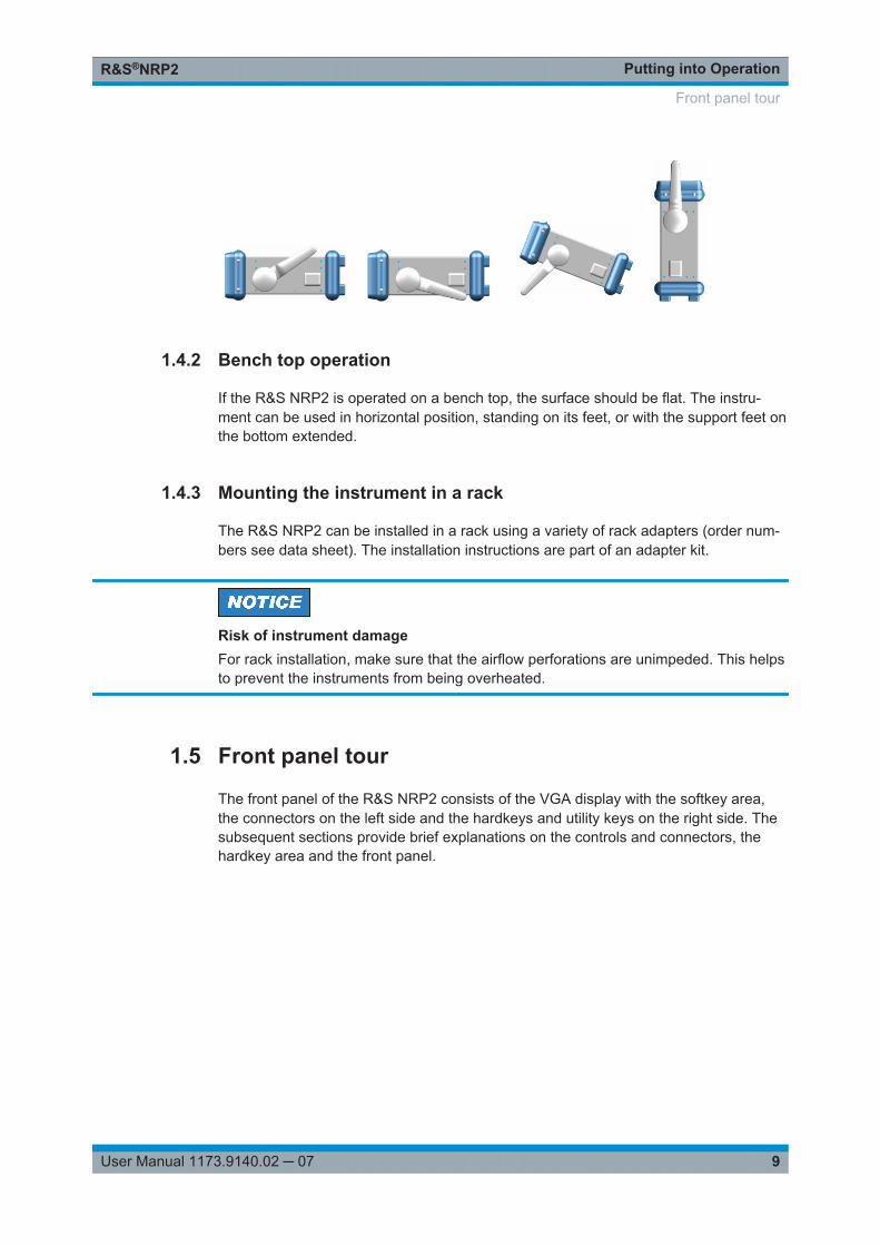
1.4.2 Bench top operation
If the R&S NRP2 is operated on a bench top, the surface should be flat. The instru-ment can be used in horizontal position, standing on its feet, or with the support feet onthe bottom extended.
1.4.3 Mounting the instrument in a rack
The R&S NRP2 can be installed in a rack using a variety of rack adapters (order num-bers see data sheet). The installation instructions are part of an adapter kit.
Risk of instrument damageFor rack installation, make sure that the airflow perforations are unimpeded. This helpsto prevent the instruments from being overheated.
1.5 Front panel tour
The front panel of the R&S NRP2 consists of the VGA display with the softkey area,the connectors on the left side and the hardkeys and utility keys on the right side. Thesubsequent sections provide brief explanations on the controls and connectors, thehardkey area and the front panel.
Front panel tour

Putting into OperationR&S®NRP2
10User Manual 1173.9140.02 ─ 07
Fig. 1-1: Front panel view
1 = POWER REF connector2 = Display3 = Softkeys4 = Hardkeys5 = Cursor keys6 = On/Standby key and standby LEDs7 = Sensor connectors
1.5.1 Display
The R&S NRP2 displays results in windows. Depending on the measurement mode,values are displayed digitally, in a combined digital and analog mode, or graphically.
The display mode can be selected individually for each measurement, i.e. you can per-form both graphical and numerical representations simultaneously.
Front panel tour
Putting into OperationR&S®NRP2
11User Manual 1173.9140.02 ─ 07
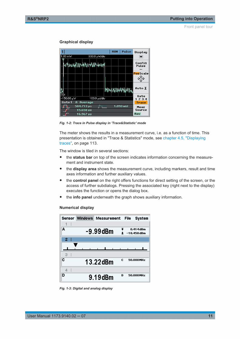
Graphical display
Fig. 1-2: Trace in Pulse display in 'Trace&Statistic' mode
The meter shows the results in a measurement curve, i.e. as a function of time. Thispresentation is obtained in "Trace & Statistics" mode, see chapter 4.5, "Displayingtraces", on page 113.
The window is tiled in several sections:● the status bar on top of the screen indicates information concerning the measure-
ment and instrument state.● the display area shows the measurement curve, including markers, result and time
axes information and further auxiliary values.● the control panel on the right offers functions for direct setting of the screen, or the
access of further subdialogs. Pressing the associated key (right next to the display)executes the function or opens the dialog box.
● the info panel underneath the graph shows auxiliary information.
Numerical display
Fig. 1-3: Digital and analog display
Front panel tour
Putting into OperationR&S®NRP2
12User Manual 1173.9140.02 ─ 07
Numerical measuring windows indicate the readings digitally, or provide the values inform of an analog meter. A maximum of four windows can be displayed on the screen,while their size is determined by the number of windows. The R&S NRP2 indicateseither all windows simultaneously, or individually expanded.
For detailed information concerning the screen layout see chapter 3.2, "Screen layout",on page 49.
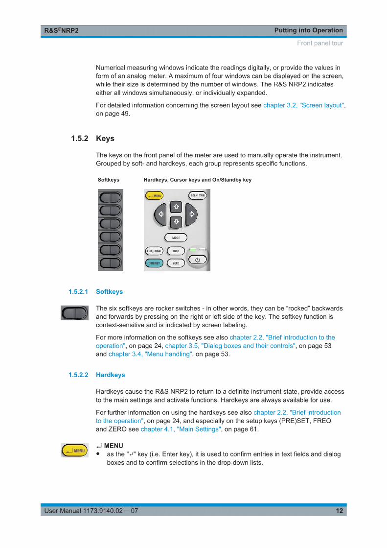
1.5.2 Keys
The keys on the front panel of the meter are used to manually operate the instrument.Grouped by soft- and hardkeys, each group represents specific functions.
Softkeys Hardkeys, Cursor keys and On/Standby key
1.5.2.1 Softkeys
The six softkeys are rocker switches - in other words, they can be “rocked” backwardsand forwards by pressing on the right or left side of the key. The softkey function iscontext-sensitive and is indicated by screen labeling.
For more information on the softkeys see also chapter 2.2, "Brief introduction to theoperation", on page 24, chapter 3.5, "Dialog boxes and their controls", on page 53and chapter 3.4, "Menu handling", on page 53.
1.5.2.2 Hardkeys
Hardkeys cause the R&S NRP2 to return to a definite instrument state, provide accessto the main settings and activate functions. Hardkeys are always available for use.
For further information on using the hardkeys see also chapter 2.2, "Brief introductionto the operation", on page 24, and especially on the setup keys (PRE)SET, FREQand ZERO see chapter 4.1, "Main Settings", on page 61.
↵ MENU● as the "↵" key (i.e. Enter key), it is used to confirm entries in text fields and dialog
boxes and to confirm selections in the drop-down lists.
Front panel tour
Putting into OperationR&S®NRP2
13User Manual 1173.9140.02 ─ 07
● as the MENU key, it is used to fold out and fold back the menus next to the soft-keys.
The function of the key is determined according to context – in other words, theENTER or MENU function is always selected automatically for the operator by theinstrument.
DEL / 1 TRIG● the DEL key is used to delete numbers or text in a field so that a completely new
entry can be made.● as the 1 TRIG key, it enables and triggers single-shot measurements in the trace
mode.The function of the key is selected automatically according to context.
ESC / LOCAL● this key is used as an ESC key to escape from the entry mode in text boxes and
drop-down lists. It is also used to close dialog boxes and menus without losing anyentries that have been made, see chapter 3.2, "Screen layout", on page 49.
● as the LOCAL key, it is used to switch the R&S NRP2 from remote control mode(all controls disabled) to manual mode.
The key is automatically assigned its function according to context - in other words,there is no manual assignment by the operator.
MODEMODE opens the "Mode" dialog box to select and configure the measurement mode.
See also chapter 4.2.1.1, "Mode dialog box", on page 65.
(PRE)SETThe (PRE)SET hardkey sets the R&S NRP2 to its default setting. Default settings aresensor specific.
The function can also be started with the "Preset" softkey in the file menu, see chap-ter 4.6.1, "Default setting", on page 141.
FREQFREQ sets the carrier frequency of the applied signal to obtain the specific measure-ment uncertainty.
Find more information on the frequency dialog box in the operating manual, chap-ter 4.1.2, "Frequency hardkey", on page 62.
ZEROThis function starts the autozero function, see also chapter 4.1.3, "Zero hardkey",on page 63.
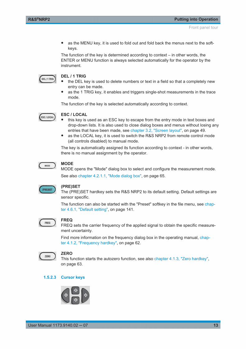
1.5.2.3 Cursor keys
Front panel tour
Putting into OperationR&S®NRP2
14User Manual 1173.9140.02 ─ 07
The cursor-key functions are context-sensitive. They are used to:● select a menu● select the active window● move the cursor in text boxes● change the value of an entry in a text box● select an element from a drop-down list
Except of moving the cursor, the above mentioned functions can also be activatedusing softkeys.
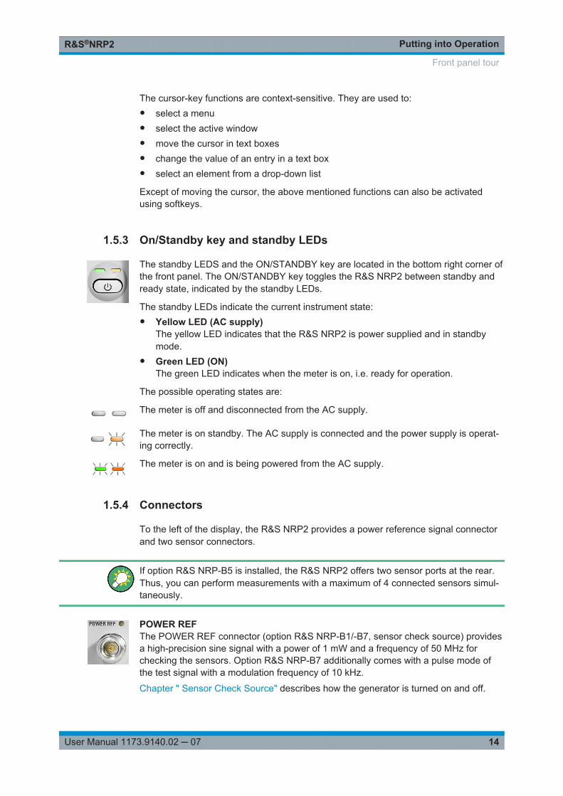
1.5.3 On/Standby key and standby LEDs
The standby LEDS and the ON/STANDBY key are located in the bottom right corner ofthe front panel. The ON/STANDBY key toggles the R&S NRP2 between standby andready state, indicated by the standby LEDs.
The standby LEDs indicate the current instrument state:● Yellow LED (AC supply)
The yellow LED indicates that the R&S NRP2 is power supplied and in standbymode.
● Green LED (ON)The green LED indicates when the meter is on, i.e. ready for operation.
The possible operating states are:
The meter is off and disconnected from the AC supply.
The meter is on standby. The AC supply is connected and the power supply is operat-ing correctly.
The meter is on and is being powered from the AC supply.
1.5.4 Connectors
To the left of the display, the R&S NRP2 provides a power reference signal connectorand two sensor connectors.
If option R&S NRP-B5 is installed, the R&S NRP2 offers two sensor ports at the rear.Thus, you can perform measurements with a maximum of 4 connected sensors simul-taneously.
POWER REFThe POWER REF connector (option R&S NRP-B1/-B7, sensor check source) providesa high-precision sine signal with a power of 1 mW and a frequency of 50 MHz forchecking the sensors. Option R&S NRP-B7 additionally comes with a pulse mode ofthe test signal with a modulation frequency of 10 kHz.
Chapter " Sensor Check Source" describes how the generator is turned on and off.
Front panel tour
Putting into OperationR&S®NRP2
15User Manual 1173.9140.02 ─ 07
Sensor connectorsThe front panel accommodates a maximum of two sensor connectors (for sen-sors A and B). Sensor connector B requires option R&S NRP-B2, second sensor input(B).
The power sensors are connected by inserting the male connector.
Note: You can not disconnect the sensor simply by pulling at the cable or the rear partof the connector. To disconnect pull the connector at its sleeve, which is marked with ared dot.
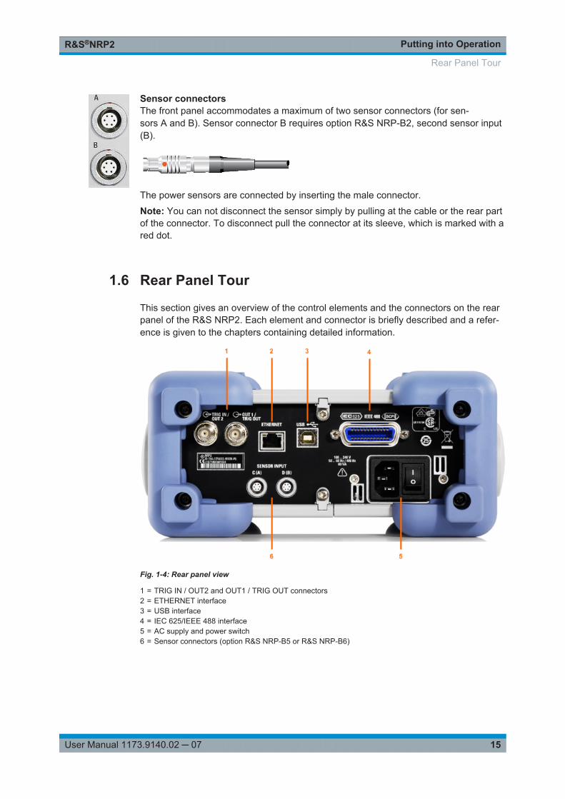
1.6 Rear Panel Tour
This section gives an overview of the control elements and the connectors on the rearpanel of the R&S NRP2. Each element and connector is briefly described and a refer-ence is given to the chapters containing detailed information.
Fig. 1-4: Rear panel view
1 = TRIG IN / OUT2 and OUT1 / TRIG OUT connectors2 = ETHERNET interface3 = USB interface4 = IEC 625/IEEE 488 interface5 = AC supply and power switch6 = Sensor connectors (option R&S NRP-B5 or R&S NRP-B6)
Rear Panel Tour
Putting into OperationR&S®NRP2
16User Manual 1173.9140.02 ─ 07
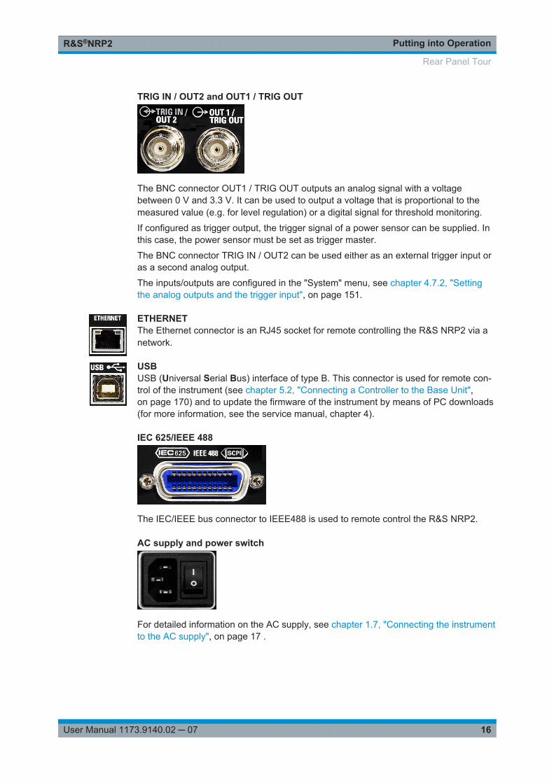
TRIG IN / OUT2 and OUT1 / TRIG OUT
The BNC connector OUT1 / TRIG OUT outputs an analog signal with a voltagebetween 0 V and 3.3 V. It can be used to output a voltage that is proportional to themeasured value (e.g. for level regulation) or a digital signal for threshold monitoring.
If configured as trigger output, the trigger signal of a power sensor can be supplied. Inthis case, the power sensor must be set as trigger master.
The BNC connector TRIG IN / OUT2 can be used either as an external trigger input oras a second analog output.
The inputs/outputs are configured in the "System" menu, see chapter 4.7.2, "Settingthe analog outputs and the trigger input", on page 151.
ETHERNETThe Ethernet connector is an RJ45 socket for remote controlling the R&S NRP2 via anetwork.
USBUSB (Universal Serial Bus) interface of type B. This connector is used for remote con-trol of the instrument (see chapter 5.2, "Connecting a Controller to the Base Unit",on page 170) and to update the firmware of the instrument by means of PC downloads(for more information, see the service manual, chapter 4).
IEC 625/IEEE 488
The IEC/IEEE bus connector to IEEE488 is used to remote control the R&S NRP2.
AC supply and power switch
For detailed information on the AC supply, see chapter 1.7, "Connecting the instrumentto the AC supply", on page 17 .
Rear Panel Tour
Putting into OperationR&S®NRP2
17User Manual 1173.9140.02 ─ 07
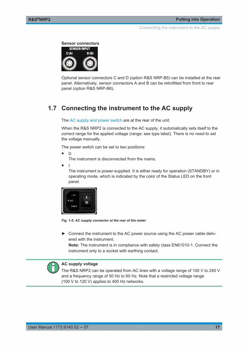
Sensor connectors
Optional sensor connectors C and D (option R&S NRP-B5) can be installed at the rearpanel. Alternatively, sensor connectors A and B can be retrofitted from front to rearpanel (option R&S NRP-B6).
1.7 Connecting the instrument to the AC supply
The AC supply and power switch are at the rear of the unit.
When the R&S NRP2 is connected to the AC supply, it automatically sets itself to thecorrect range for the applied voltage (range: see type label). There is no need to setthe voltage manually.
The power switch can be set to two positions:● 0:
The instrument is disconnected from the mains.● I
The instrument is power-supplied. It is either ready for operation (STANDBY) or inoperating mode, which is indicated by the color of the Status LED on the frontpanel.
Fig. 1-5: AC supply connector at the rear of the meter
► Connect the instrument to the AC power source using the AC power cable deliv-ered with the instrument.Note: The instrument is in compliance with safety class EN61010-1. Connect theinstrument only to a socket with earthing contact.
AC supply voltageThe R&S NRP2 can be operated from AC lines with a voltage range of 100 V to 240 Vand a frequency range of 50 Hz to 60 Hz. Note that a restricted voltage range(100 V to 120 V) applies to 400 Hz networks.
Connecting the instrument to the AC supply
Putting into OperationR&S®NRP2
18User Manual 1173.9140.02 ─ 07
1.8 Starting the R&S NRP2
1.8.1 Switching on
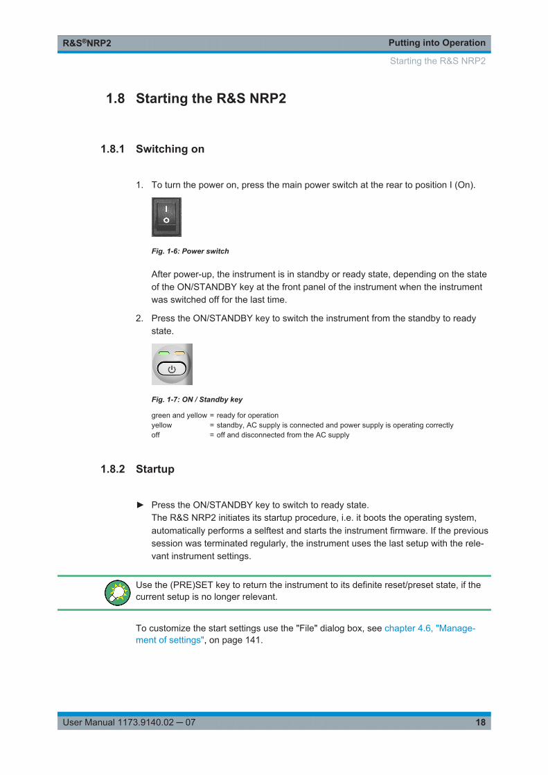
1. To turn the power on, press the main power switch at the rear to position I (On).
Fig. 1-6: Power switch
After power-up, the instrument is in standby or ready state, depending on the stateof the ON/STANDBY key at the front panel of the instrument when the instrumentwas switched off for the last time.
2. Press the ON/STANDBY key to switch the instrument from the standby to readystate.
Fig. 1-7: ON / Standby key
green and yellow = ready for operationyellow = standby, AC supply is connected and power supply is operating correctlyoff = off and disconnected from the AC supply
1.8.2 Startup
► Press the ON/STANDBY key to switch to ready state.The R&S NRP2 initiates its startup procedure, i.e. it boots the operating system,automatically performs a selftest and starts the instrument firmware. If the previoussession was terminated regularly, the instrument uses the last setup with the rele-vant instrument settings.
Use the (PRE)SET key to return the instrument to its definite reset/preset state, if thecurrent setup is no longer relevant.
To customize the start settings use the "File" dialog box, see chapter 4.6, "Manage-ment of settings", on page 141.
Starting the R&S NRP2
Putting into OperationR&S®NRP2
19User Manual 1173.9140.02 ─ 07
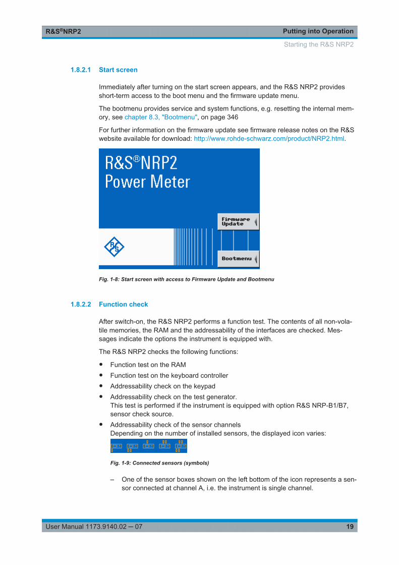
1.8.2.1 Start screen
Immediately after turning on the start screen appears, and the R&S NRP2 providesshort-term access to the boot menu and the firmware update menu.
The bootmenu provides service and system functions, e.g. resetting the internal mem-ory, see chapter 8.3, "Bootmenu", on page 346
For further information on the firmware update see firmware release notes on the R&Swebsite available for download: http://www.rohde-schwarz.com/product/NRP2.html.
Fig. 1-8: Start screen with access to Firmware Update and Bootmenu
1.8.2.2 Function check
After switch-on, the R&S NRP2 performs a function test. The contents of all non-vola-tile memories, the RAM and the addressability of the interfaces are checked. Mes-sages indicate the options the instrument is equipped with.
The R&S NRP2 checks the following functions:
● Function test on the RAM● Function test on the keyboard controller● Addressability check on the keypad● Addressability check on the test generator.
This test is performed if the instrument is equipped with option R&S NRP-B1/B7,sensor check source.
● Addressability check of the sensor channelsDepending on the number of installed sensors, the displayed icon varies:
Fig. 1-9: Connected sensors (symbols)
– One of the sensor boxes shown on the left bottom of the icon represents a sen-sor connected at channel A, i.e. the instrument is single channel.
Starting the R&S NRP2
Putting into OperationR&S®NRP2
20User Manual 1173.9140.02 ─ 07
– Two sensor boxes indicate that channels A and B are connected, fitted at thefront panel (requires option NRP-B2, the second measurement input).
– Accordingly, one or two sensor boxes shown on top indicate that channels Aand B are fitted at the rear panel with option NRP-B6, sensor connectors A (B).
– Four sensor boxes indicate that the meter supports channels A to D, optionNRP-B5, 3rd and 4th measurement input.
● Addressability check on the USB interface● Addressability check of the Ethernet interface
The instrument performs a test on the Ethernet interface, and displays the trans-mission rate, e.g. . When finished, the instrument displays the result under thenetwork icon, i.e. "OK" indicates that the interface can be addressed.If the R&S NRP2 is not connected to a network hub or if a connection cannot beestablished during booting, the message (Not Connected) is displayed insteadof "OK". It is however possible to establish a network connection later on at anytime.
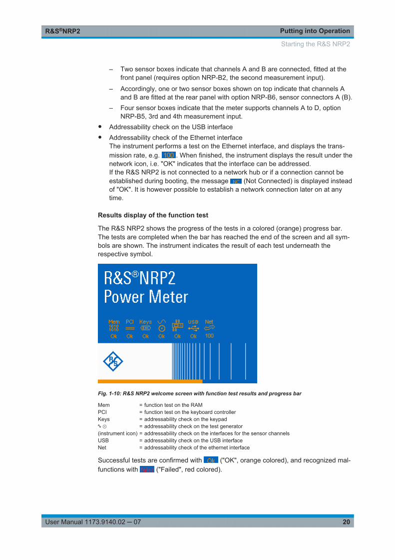
Results display of the function test
The R&S NRP2 shows the progress of the tests in a colored (orange) progress bar.The tests are completed when the bar has reached the end of the screen and all sym-bols are shown. The instrument indicates the result of each test underneath therespective symbol.
Fig. 1-10: R&S NRP2 welcome screen with function test results and progress bar
Mem = function test on the RAMPCI = function test on the keyboard controllerKeys = addressability check on the keypad∿ ⊙ = addressability check on the test generator(instrument icon) = addressability check on the interfaces for the sensor channelsUSB = addressability check on the USB interfaceNet = addressability check of the ethernet interface
Successful tests are confirmed with ("OK", orange colored), and recognized mal-functions with ("Failed", red colored).
Starting the R&S NRP2
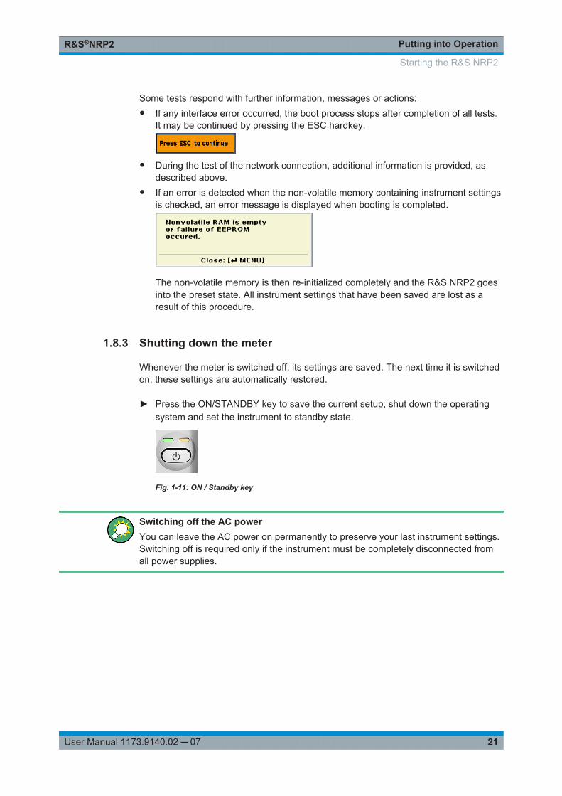
Putting into OperationR&S®NRP2
21User Manual 1173.9140.02 ─ 07
Some tests respond with further information, messages or actions:● If any interface error occurred, the boot process stops after completion of all tests.
It may be continued by pressing the ESC hardkey.
● During the test of the network connection, additional information is provided, asdescribed above.
● If an error is detected when the non-volatile memory containing instrument settingsis checked, an error message is displayed when booting is completed.
The non-volatile memory is then re-initialized completely and the R&S NRP2 goesinto the preset state. All instrument settings that have been saved are lost as aresult of this procedure.
1.8.3 Shutting down the meter
Whenever the meter is switched off, its settings are saved. The next time it is switchedon, these settings are automatically restored.
► Press the ON/STANDBY key to save the current setup, shut down the operatingsystem and set the instrument to standby state.
Fig. 1-11: ON / Standby key
Switching off the AC powerYou can leave the AC power on permanently to preserve your last instrument settings.Switching off is required only if the instrument must be completely disconnected fromall power supplies.
Starting the R&S NRP2

Putting into OperationR&S®NRP2
22User Manual 1173.9140.02 ─ 07
Starting the R&S NRP2
Getting StartedR&S®NRP2
23User Manual 1173.9140.02 ─ 07
2 Getting StartedThis chapter introduces the main functions and settings of the R&S NRP2, by means ofsome basic power measurement examples.
Included topics:● Brief introduction to the operation, on page 24 provides a quick introduction on
how to operate the instrument.● Preset and zeroing, on page 27 explains how to set the R&S NRP2 and the R&S
Power Sensors to defined initial states.● Measuring average power (Cont Av mode), on page 29 introduces standard
power measurement with the R&S NRP2.● Window handling, on page 36 and Setting measurement functions, on page 41
explains the basic techniques for configuring result windows.● Graphically representing power versus time, on page 43 represents graphically
the time characteristics in "Trace & Statistics" mode.● Measuring average burst power (Burst Av mode), on page 47. enables you to
perform a measurement of burst power without external triggering.
Some of the sections later on in this chapter assume familiarity with the basic operatingtechniques which are introduced in the first sections. It is, therefore, advisable to gothrough these sections first before considering other topics.
An in-depth description of the operation of the instrument is described in chapter 3,"Manual Operation", on page 49.
2.1 Requirements
● Read the notes on putting the meter into operation in chapter 1.1, "Notes on puttinginto operation", on page 7.
● A single-channel R&S NRP2 is sufficient for most of the examples used in thesequel. However, if you want to work through all the steps in chapter 2.6, "Settingmeasurement functions", on page 41 you will need a dual-channel instrument.
● Any sensor of the R&S NRP-Zx series is suitable.● A signal source is required for the following measurements. It is best to use a sig-
nal generator whose level can be adjusted. If a generator of this type is not availa-ble, the R&S NRP2’s integral power reference (option R&S NRP-B1/-B7) can beused instead.
Requirements
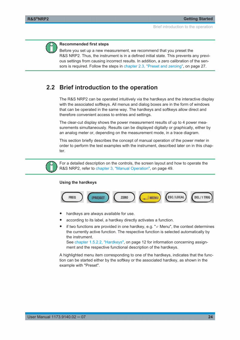
Getting StartedR&S®NRP2
24User Manual 1173.9140.02 ─ 07
Recommended first stepsBefore you set up a new measurement, we recommend that you preset theR&S NRP2. Thus, the instrument is in a defined initial state. This prevents any previ-ous settings from causing incorrect results. In addition, a zero calibration of the sen-sors is required. Follow the steps in chapter 2.3, "Preset and zeroing", on page 27.
2.2 Brief introduction to the operation
The R&S NRP2 can be operated intuitively via the hardkeys and the interactive displaywith the associated softkeys. All menus and dialog boxes are in the form of windowsthat can be operated in the same way. The hardkeys and softkeys allow direct andtherefore convenient access to entries and settings.
The clear-cut display shows the power measurement results of up to 4 power mea-surements simultaneously. Results can be displayed digitally or graphically, either byan analog meter or, depending on the measurement mode, in a trace diagram.
This section briefly describes the concept of manual operation of the power meter inorder to perform the test examples with the instrument, described later on in this chap-ter.
For a detailed description on the controls, the screen layout and how to operate theR&S NRP2, refer to chapter 3, "Manual Operation", on page 49.
Using the hardkeys
● hardkeys are always available for use.● according to its label, a hardkey directly activates a function.● if two functions are provided in one hardkey, e.g. "↵ Menu", the context determines
the currently active function. The respective function is selected automatically bythe instrument.See chapter 1.5.2.2, "Hardkeys", on page 12 for information concerning assign-ment and the respective functional description of the hardkeys.
A highlighted menu item corresponding to one of the hardkeys, indicates that the func-tion can be started either by the softkey or the associated hardkey, as shown in theexample with "Preset".
Brief introduction to the operation
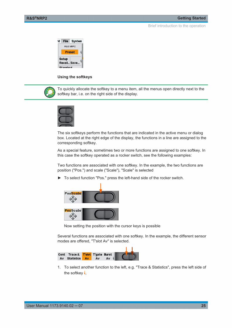
Getting StartedR&S®NRP2
25User Manual 1173.9140.02 ─ 07
Using the softkeys
To quickly allocate the softkey to a menu item, all the menus open directly next to thesoftkey bar, i.e. on the right side of the display.
The six softkeys perform the functions that are indicated in the active menu or dialogbox. Located at the right edge of the display, the functions in a line are assigned to thecorresponding softkey.
As a special feature, sometimes two or more functions are assigned to one softkey. Inthis case the softkey operated as a rocker switch, see the following examples:
Two functions are associated with one softkey. In the example, the two functions areposition ("Pos.") and scale ("Scale"), "Scale" is selected
► To select function "Pos." press the left-hand side of the rocker switch.
Now setting the position with the cursor keys is possible
Several functions are associated with one softkey. In the example, the different sensormodes are offered, "T'slot Av" is selected.
1. To select another function to the left, e.g. "Trace & Statistics", press the left side ofthe softkey ,
Brief introduction to the operation
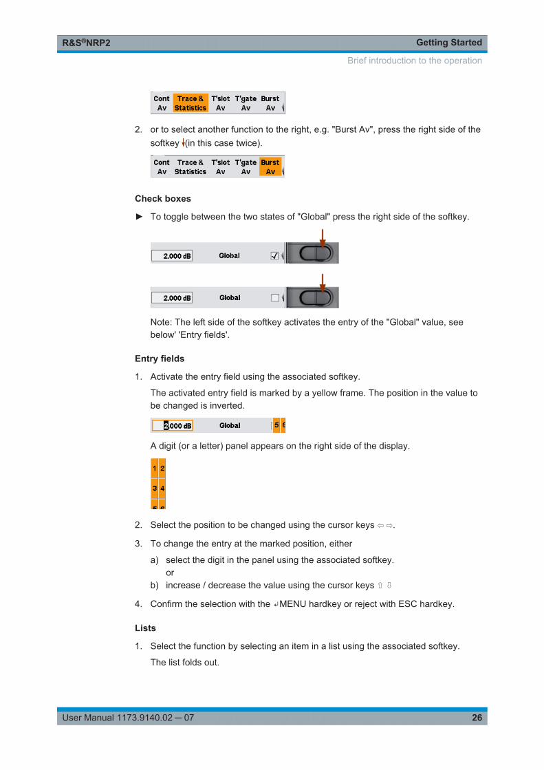
Getting StartedR&S®NRP2
26User Manual 1173.9140.02 ─ 07
2. or to select another function to the right, e.g. "Burst Av", press the right side of thesoftkey (in this case twice).
Check boxes
► To toggle between the two states of "Global" press the right side of the softkey.
Note: The left side of the softkey activates the entry of the "Global" value, seebelow' 'Entry fields'.
Entry fields
1. Activate the entry field using the associated softkey.
The activated entry field is marked by a yellow frame. The position in the value tobe changed is inverted.
A digit (or a letter) panel appears on the right side of the display.
2. Select the position to be changed using the cursor keys ⇦ ⇨.
3. To change the entry at the marked position, either
a) select the digit in the panel using the associated softkey.or
b) increase / decrease the value using the cursor keys ⇧ ⇩
4. Confirm the selection with the ↵MENU hardkey or reject with ESC hardkey.
Lists
1. Select the function by selecting an item in a list using the associated softkey.
The list folds out.
Brief introduction to the operation
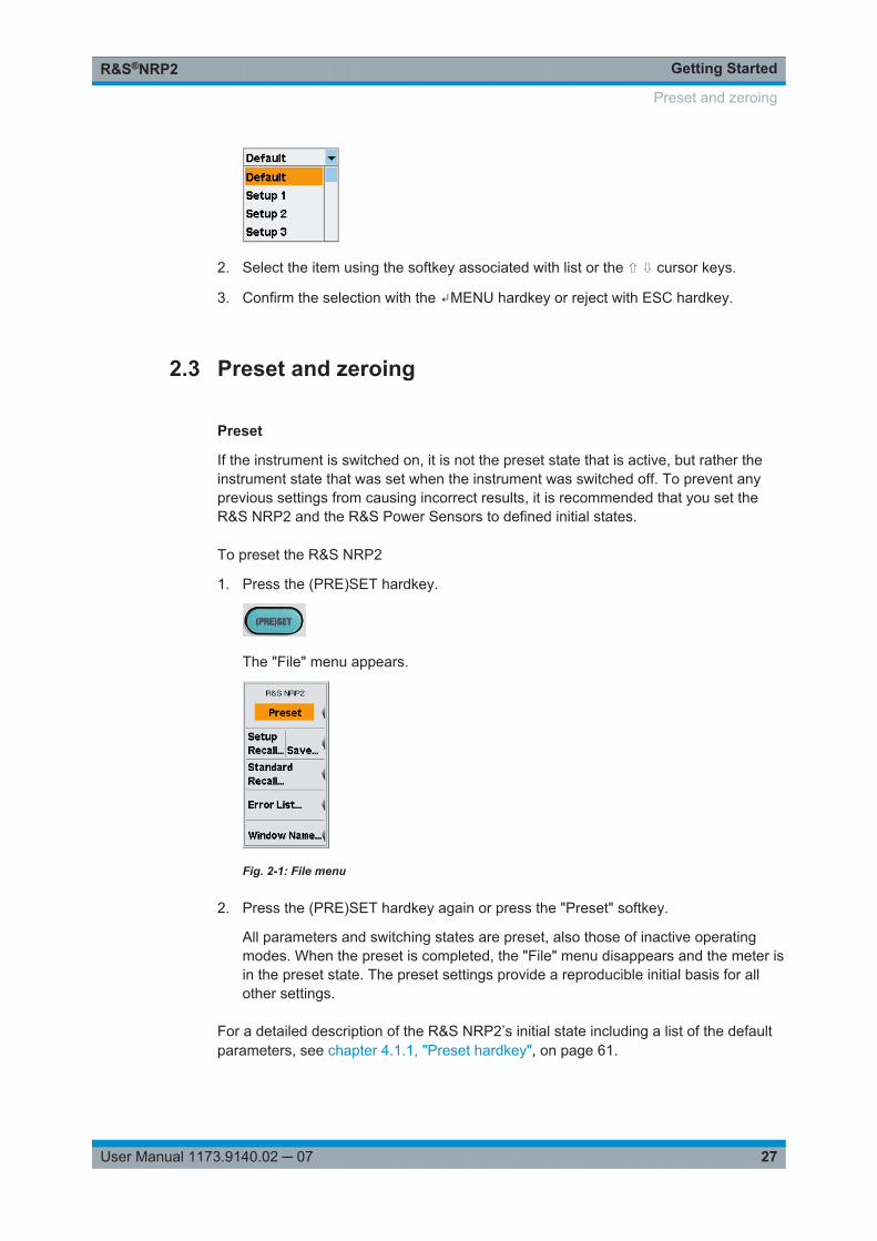
Getting StartedR&S®NRP2
27User Manual 1173.9140.02 ─ 07
2. Select the item using the softkey associated with list or the ⇧ ⇩ cursor keys.
3. Confirm the selection with the ↵MENU hardkey or reject with ESC hardkey.
2.3 Preset and zeroing
Preset
If the instrument is switched on, it is not the preset state that is active, but rather theinstrument state that was set when the instrument was switched off. To prevent anyprevious settings from causing incorrect results, it is recommended that you set theR&S NRP2 and the R&S Power Sensors to defined initial states.
To preset the R&S NRP2
1. Press the (PRE)SET hardkey.
The "File" menu appears.
Fig. 2-1: File menu
2. Press the (PRE)SET hardkey again or press the "Preset" softkey.
All parameters and switching states are preset, also those of inactive operatingmodes. When the preset is completed, the "File" menu disappears and the meter isin the preset state. The preset settings provide a reproducible initial basis for allother settings.
For a detailed description of the R&S NRP2’s initial state including a list of the defaultparameters, see chapter 4.1.1, "Preset hardkey", on page 61.
Preset and zeroing

Getting StartedR&S®NRP2
28User Manual 1173.9140.02 ─ 07
Zeroing
Zeroing should be performed whenever necessary. As a rule of thumb, this is the casefor measurements of power values less than a 1000 fold of the zero offset and after thesensor has reached its operating temperature.
Turn off all test signals before zeroing. An active test signal during zeroing causes anerror.
To zero the meter
1. Connect the sensor to a signal source
2. Switch off the power
3. Press the ZERO hardkey.
The "Zero" dialog box is displayed.
Fig. 2-2: Zeroing dialog box
4. Press the ZERO hardkey again to perform zeroing of all connected sensor chan-nels ("Zero (All)") or press the appropriate softkey to select a specific sensor forzeroing.
Zeroing of all connected sensors is performed.
The correction measurement takes several seconds. When completed, theR&S NRP2 displays a message indicating success or failure of zeroing.
Preset and zeroing
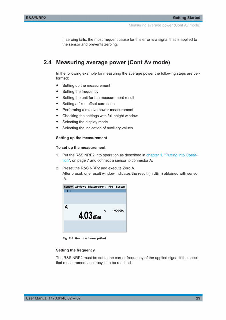
Getting StartedR&S®NRP2
29User Manual 1173.9140.02 ─ 07
If zeroing fails, the most frequent cause for this error is a signal that is applied tothe sensor and prevents zeroing.
2.4 Measuring average power (Cont Av mode)
In the following example for measuring the average power the following steps are per-formed:
● Setting up the measurement● Setting the frequency● Setting the unit for the measurement result● Setting a fixed offset correction● Performing a relative power measurement● Checking the settings with full height window● Selecting the display mode● Selecting the indication of auxiliary values
Setting up the measurement
To set up the measurement
1. Put the R&S NRP2 into operation as described in chapter 1, "Putting into Opera-tion", on page 7 and connect a sensor to connector A.
2. Preset the R&S NRP2 and execute Zero A.After preset, one result window indicates the result (in dBm) obtained with sensor A.
Fig. 2-3: Result window (dBm)
Setting the frequency
The R&S NRP2 must be set to the carrier frequency of the applied signal if the speci-fied measurement accuracy is to be reached.
Measuring average power (Cont Av mode)
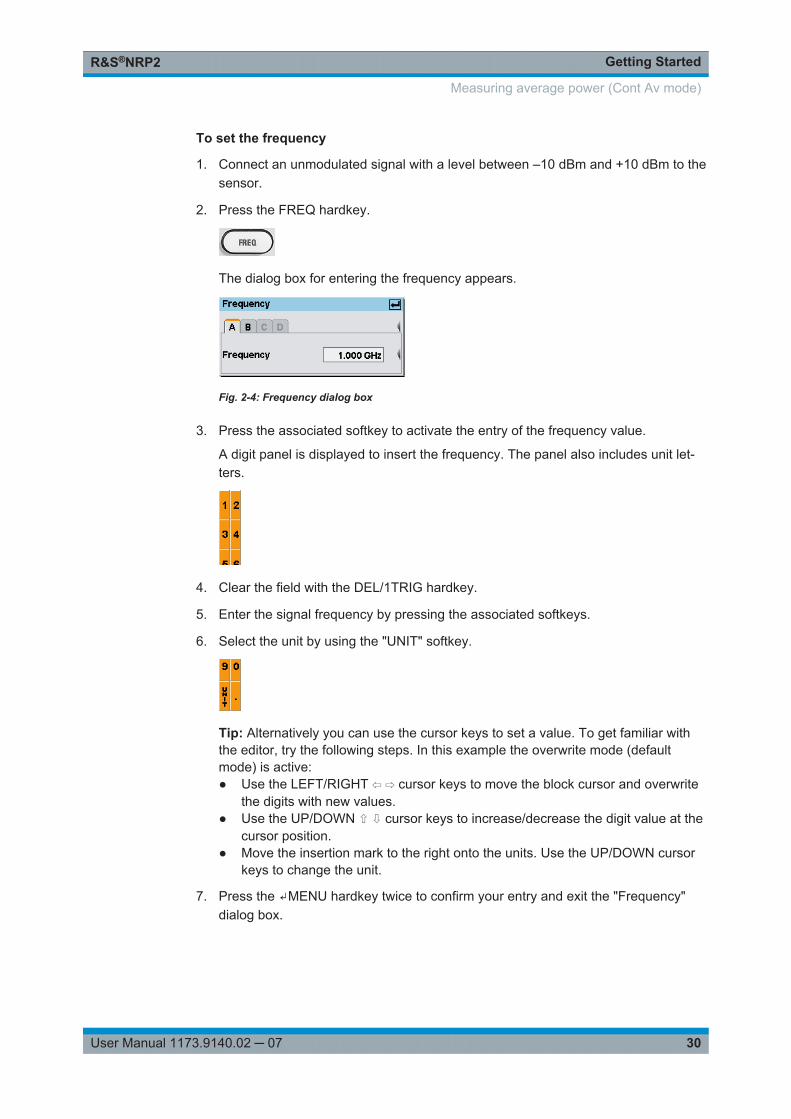
Getting StartedR&S®NRP2
30User Manual 1173.9140.02 ─ 07
To set the frequency
1. Connect an unmodulated signal with a level between –10 dBm and +10 dBm to thesensor.
2. Press the FREQ hardkey.
The dialog box for entering the frequency appears.
Fig. 2-4: Frequency dialog box
3. Press the associated softkey to activate the entry of the frequency value.
A digit panel is displayed to insert the frequency. The panel also includes unit let-ters.
4. Clear the field with the DEL/1TRIG hardkey.
5. Enter the signal frequency by pressing the associated softkeys.
6. Select the unit by using the "UNIT" softkey.
Tip: Alternatively you can use the cursor keys to set a value. To get familiar withthe editor, try the following steps. In this example the overwrite mode (defaultmode) is active:● Use the LEFT/RIGHT ⇦ ⇨ cursor keys to move the block cursor and overwrite
the digits with new values.● Use the UP/DOWN ⇧ ⇩ cursor keys to increase/decrease the digit value at the
cursor position.● Move the insertion mark to the right onto the units. Use the UP/DOWN cursor
keys to change the unit.
7. Press the ↵MENU hardkey twice to confirm your entry and exit the "Frequency"dialog box.
Measuring average power (Cont Av mode)
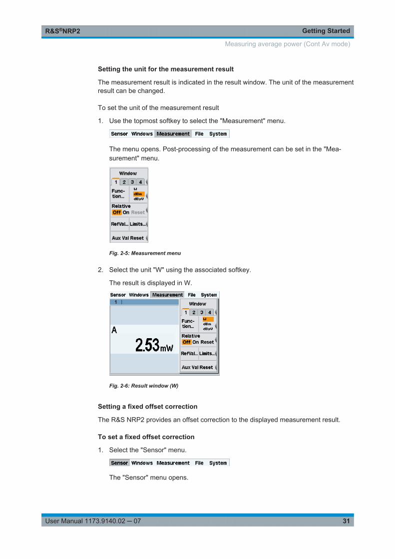
Getting StartedR&S®NRP2
31User Manual 1173.9140.02 ─ 07
Setting the unit for the measurement result
The measurement result is indicated in the result window. The unit of the measurementresult can be changed.
To set the unit of the measurement result
1. Use the topmost softkey to select the "Measurement" menu.
The menu opens. Post-processing of the measurement can be set in the "Mea-surement" menu.
Fig. 2-5: Measurement menu
2. Select the unit "W" using the associated softkey.
The result is displayed in W.
Fig. 2-6: Result window (W)
Setting a fixed offset correction
The R&S NRP2 provides an offset correction to the displayed measurement result.
To set a fixed offset correction
1. Select the "Sensor" menu.
The "Sensor" menu opens.
Measuring average power (Cont Av mode)
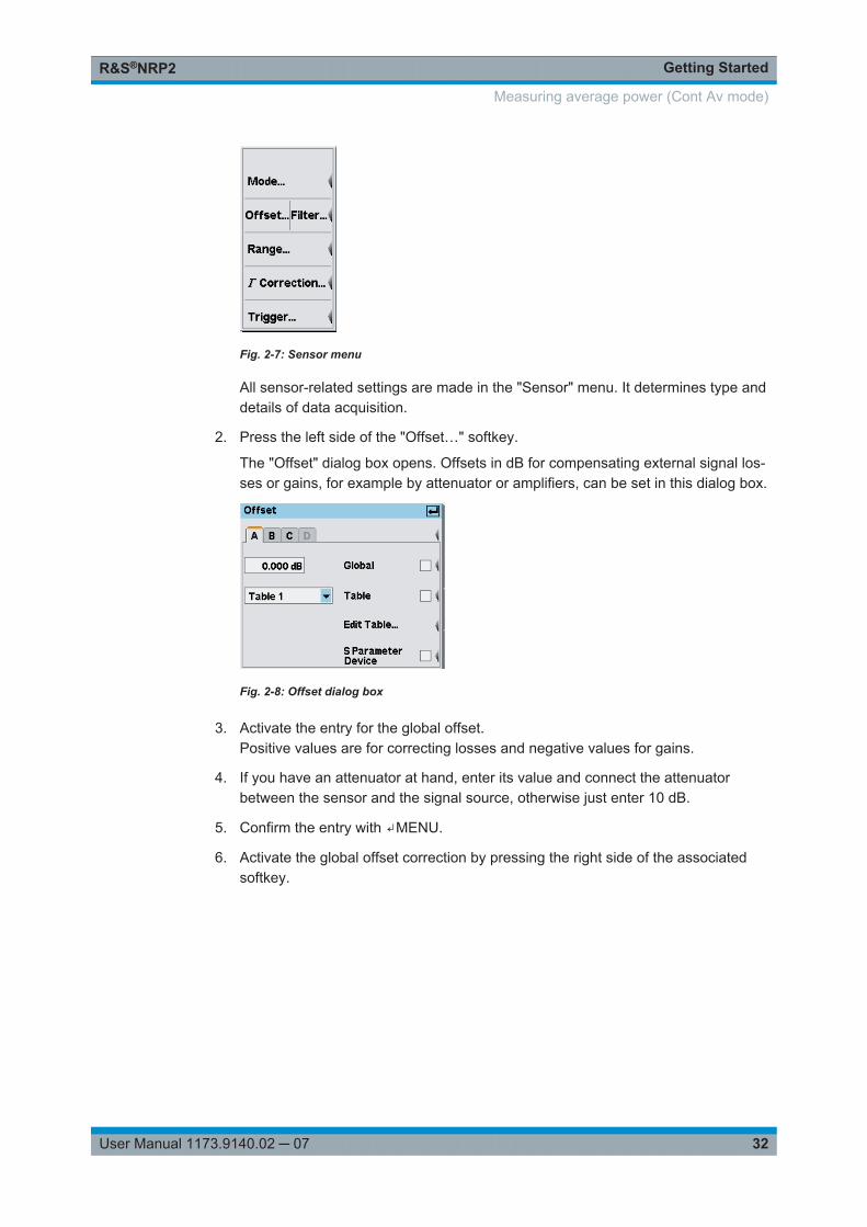
Getting StartedR&S®NRP2
32User Manual 1173.9140.02 ─ 07
Fig. 2-7: Sensor menu
All sensor-related settings are made in the "Sensor" menu. It determines type anddetails of data acquisition.
2. Press the left side of the "Offset…" softkey.
The "Offset" dialog box opens. Offsets in dB for compensating external signal los-ses or gains, for example by attenuator or amplifiers, can be set in this dialog box.
Fig. 2-8: Offset dialog box
3. Activate the entry for the global offset.Positive values are for correcting losses and negative values for gains.
4. If you have an attenuator at hand, enter its value and connect the attenuatorbetween the sensor and the signal source, otherwise just enter 10 dB.
5. Confirm the entry with ↵MENU.
6. Activate the global offset correction by pressing the right side of the associatedsoftkey.
Measuring average power (Cont Av mode)
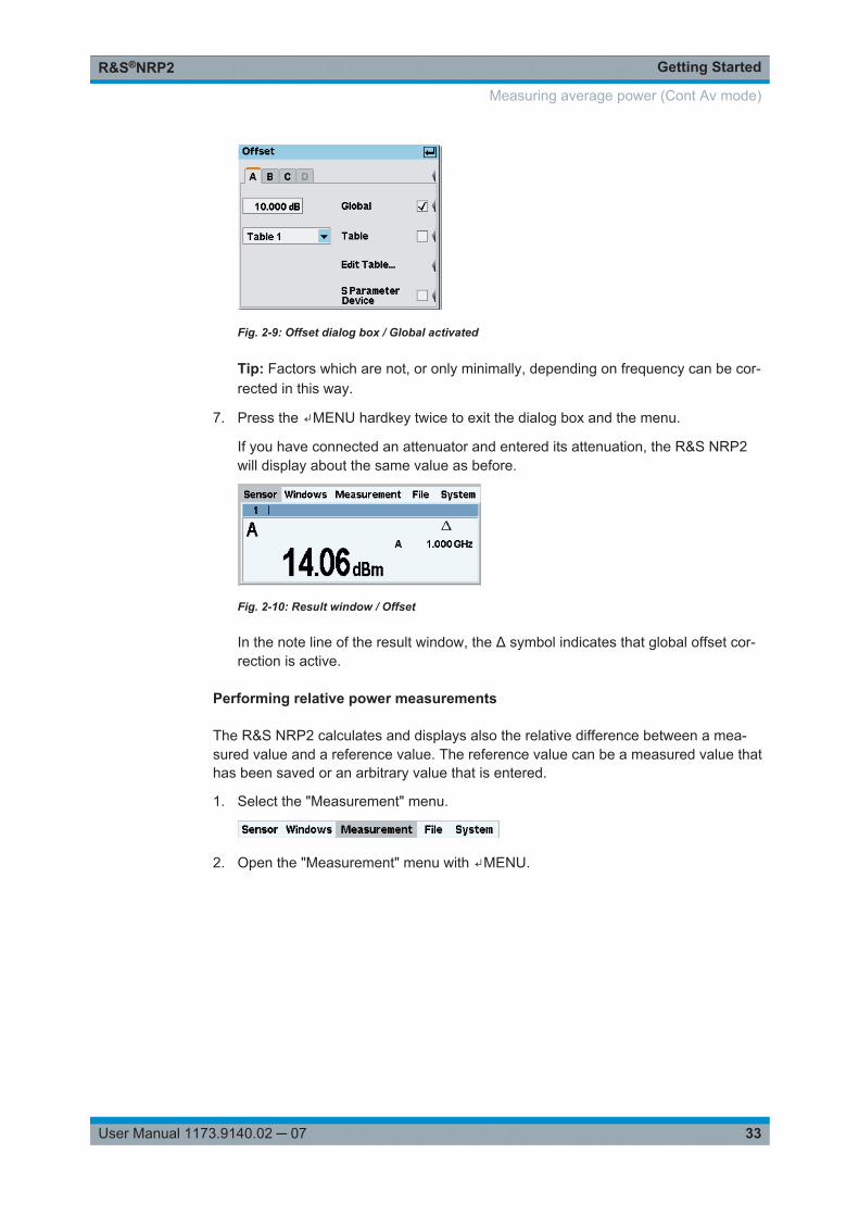
Getting StartedR&S®NRP2
33User Manual 1173.9140.02 ─ 07
Fig. 2-9: Offset dialog box / Global activated
Tip: Factors which are not, or only minimally, depending on frequency can be cor-rected in this way.
7. Press the ↵MENU hardkey twice to exit the dialog box and the menu.
If you have connected an attenuator and entered its attenuation, the R&S NRP2will display about the same value as before.
Fig. 2-10: Result window / Offset
In the note line of the result window, the Δ symbol indicates that global offset cor-rection is active.
Performing relative power measurements
The R&S NRP2 calculates and displays also the relative difference between a mea-sured value and a reference value. The reference value can be a measured value thathas been saved or an arbitrary value that is entered.
1. Select the "Measurement" menu.
2. Open the "Measurement" menu with ↵MENU.
Measuring average power (Cont Av mode)
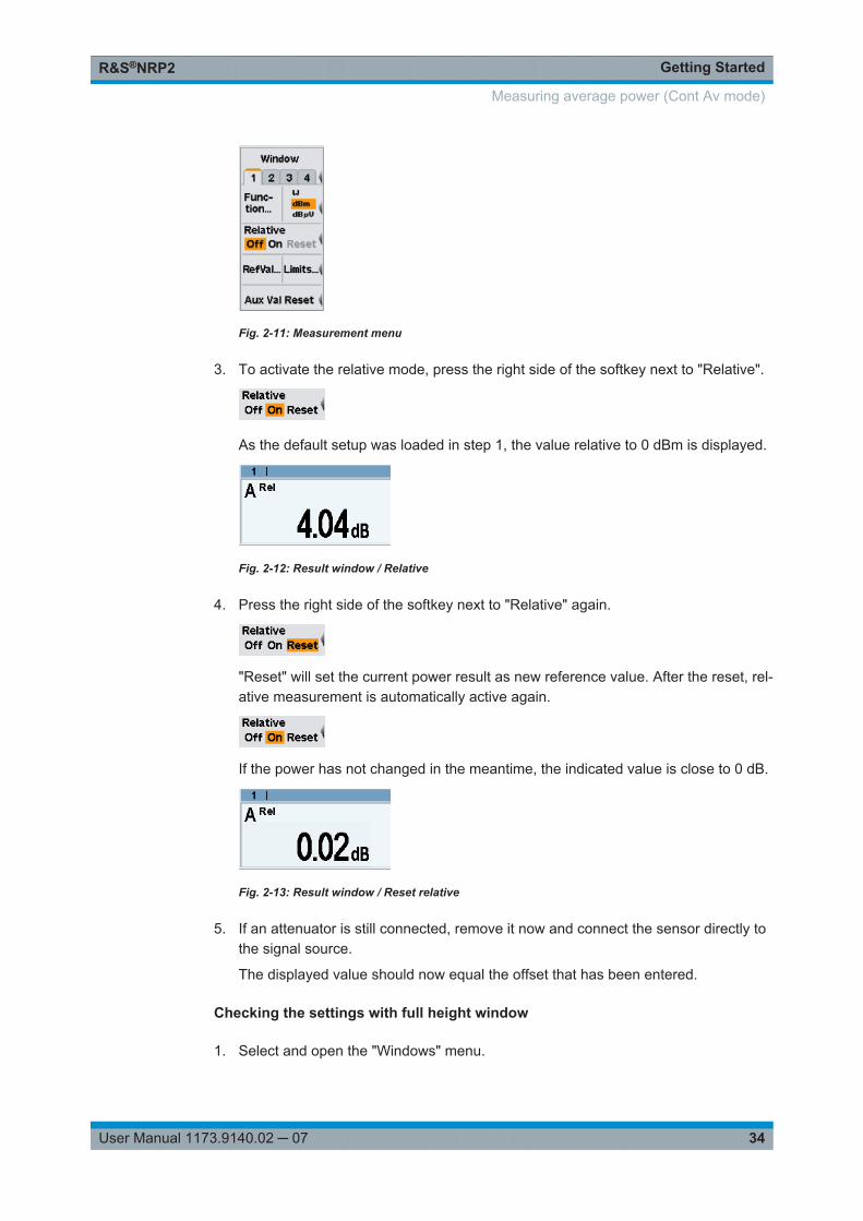
Getting StartedR&S®NRP2
34User Manual 1173.9140.02 ─ 07
Fig. 2-11: Measurement menu
3. To activate the relative mode, press the right side of the softkey next to "Relative".
As the default setup was loaded in step 1, the value relative to 0 dBm is displayed.
Fig. 2-12: Result window / Relative
4. Press the right side of the softkey next to "Relative" again.
"Reset" will set the current power result as new reference value. After the reset, rel-ative measurement is automatically active again.
If the power has not changed in the meantime, the indicated value is close to 0 dB.
Fig. 2-13: Result window / Reset relative
5. If an attenuator is still connected, remove it now and connect the sensor directly tothe signal source.
The displayed value should now equal the offset that has been entered.
Checking the settings with full height window
1. Select and open the "Windows" menu.
Measuring average power (Cont Av mode)
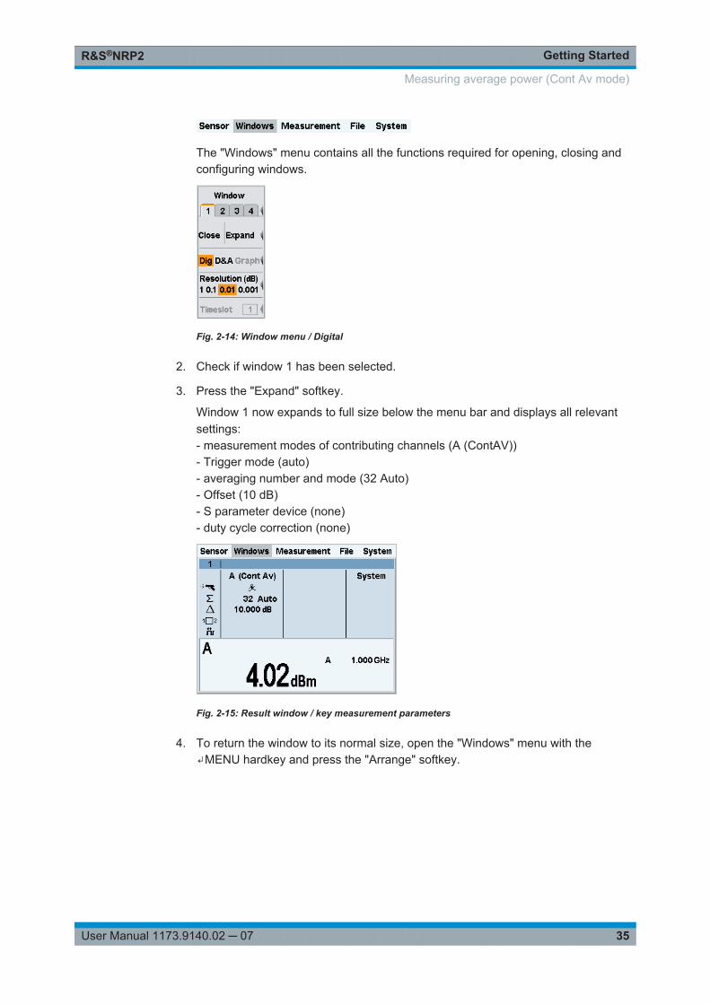
Getting StartedR&S®NRP2
35User Manual 1173.9140.02 ─ 07
The "Windows" menu contains all the functions required for opening, closing andconfiguring windows.
Fig. 2-14: Window menu / Digital
2. Check if window 1 has been selected.
3. Press the "Expand" softkey.
Window 1 now expands to full size below the menu bar and displays all relevantsettings:- measurement modes of contributing channels (A (ContAV))- Trigger mode (auto)- averaging number and mode (32 Auto)- Offset (10 dB)- S parameter device (none)- duty cycle correction (none)
Fig. 2-15: Result window / key measurement parameters
4. To return the window to its normal size, open the "Windows" menu with the↵MENU hardkey and press the "Arrange" softkey.
Measuring average power (Cont Av mode)
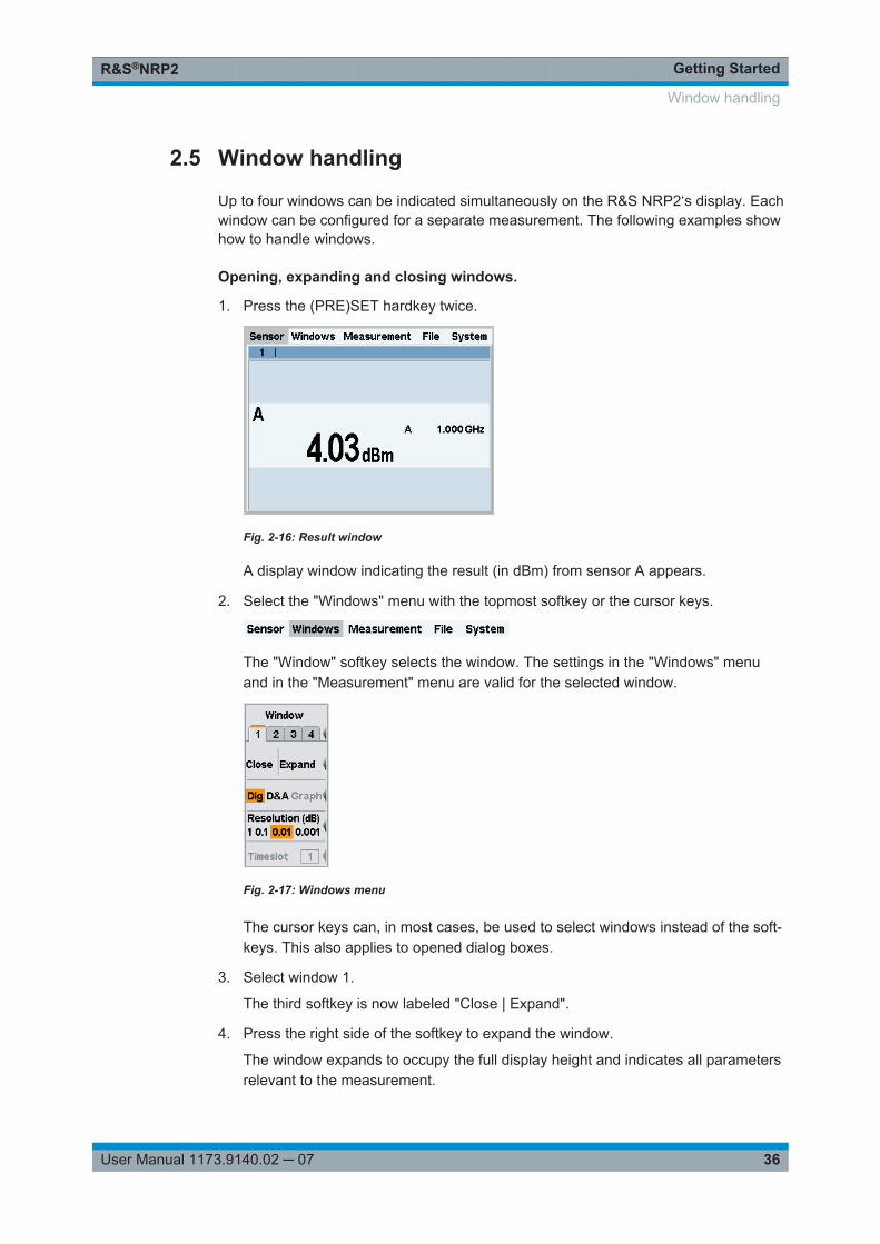
Getting StartedR&S®NRP2
36User Manual 1173.9140.02 ─ 07
2.5 Window handling
Up to four windows can be indicated simultaneously on the R&S NRP2‘s display. Eachwindow can be configured for a separate measurement. The following examples showhow to handle windows.
Opening, expanding and closing windows.
1. Press the (PRE)SET hardkey twice.
Fig. 2-16: Result window
A display window indicating the result (in dBm) from sensor A appears.
2. Select the "Windows" menu with the topmost softkey or the cursor keys.
The "Window" softkey selects the window. The settings in the "Windows" menuand in the "Measurement" menu are valid for the selected window.
Fig. 2-17: Windows menu
The cursor keys can, in most cases, be used to select windows instead of the soft-keys. This also applies to opened dialog boxes.
3. Select window 1.
The third softkey is now labeled "Close | Expand".
4. Press the right side of the softkey to expand the window.
The window expands to occupy the full display height and indicates all parametersrelevant to the measurement.
Window handling
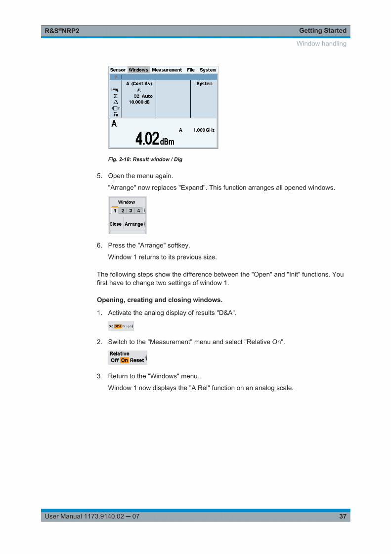
Getting StartedR&S®NRP2
37User Manual 1173.9140.02 ─ 07
Fig. 2-18: Result window / Dig
5. Open the menu again.
"Arrange" now replaces "Expand". This function arranges all opened windows.
6. Press the "Arrange" softkey.
Window 1 returns to its previous size.
The following steps show the difference between the "Open" and "Init" functions. Youfirst have to change two settings of window 1.
Opening, creating and closing windows.
1. Activate the analog display of results "D&A".
2. Switch to the "Measurement" menu and select "Relative On".
3. Return to the "Windows" menu.
Window 1 now displays the "A Rel" function on an analog scale.
Window handling
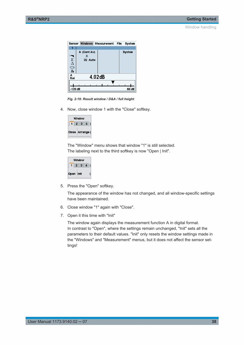
Getting StartedR&S®NRP2
38User Manual 1173.9140.02 ─ 07
Fig. 2-19: Result window / D&A / full height
4. Now, close window 1 with the "Close" softkey.
The "Window" menu shows that window "1" is still selected.The labeling next to the third softkey is now "Open | Init".
5. Press the "Open" softkey.
The appearance of the window has not changed, and all window-specific settingshave been maintained.
6. Close window "1" again with "Close".
7. Open it this time with "Init"
The window again displays the measurement function A in digital format.In contrast to "Open", where the settings remain unchanged, "Init" sets all theparameters to their default values. "Init" only resets the window settings made inthe "Windows" and "Measurement" menus, but it does not affect the sensor set-tings!
Window handling
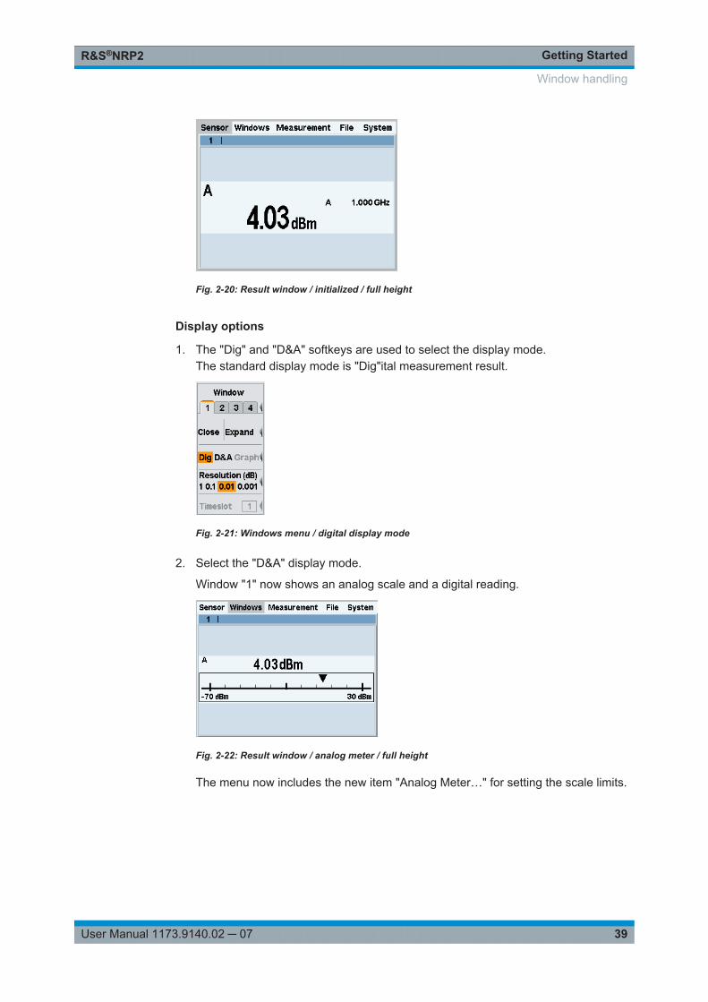
Getting StartedR&S®NRP2
39User Manual 1173.9140.02 ─ 07
Fig. 2-20: Result window / initialized / full height
Display options
1. The "Dig" and "D&A" softkeys are used to select the display mode.The standard display mode is "Dig"ital measurement result.
Fig. 2-21: Windows menu / digital display mode
2. Select the "D&A" display mode.
Window "1" now shows an analog scale and a digital reading.
Fig. 2-22: Result window / analog meter / full height
The menu now includes the new item "Analog Meter…" for setting the scale limits.
Window handling
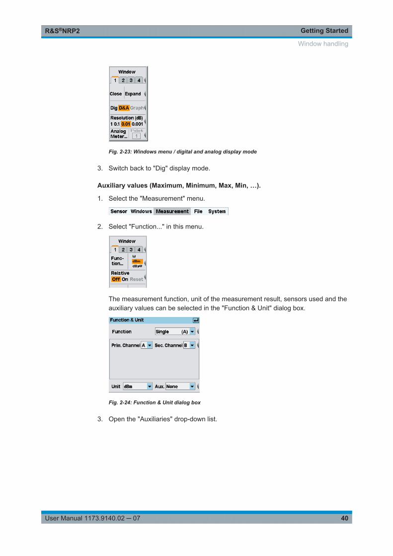
Getting StartedR&S®NRP2
40User Manual 1173.9140.02 ─ 07
Fig. 2-23: Windows menu / digital and analog display mode
3. Switch back to "Dig" display mode.
Auxiliary values (Maximum, Minimum, Max, Min, …).
1. Select the "Measurement" menu.
2. Select "Function..." in this menu.
The measurement function, unit of the measurement result, sensors used and theauxiliary values can be selected in the "Function & Unit" dialog box.
Fig. 2-24: Function & Unit dialog box
3. Open the "Auxiliaries" drop-down list.
Window handling
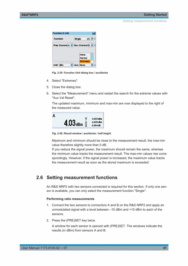
Getting StartedR&S®NRP2
41User Manual 1173.9140.02 ─ 07
Fig. 2-25: Function Unit dialog box / auxiliaries
4. Select "Extremes".
5. Close the dialog box.
6. Select the "Measurement" menu and restart the search for the extreme values with"Aux Val Reset".
The updated maximum, minimum and max-min are now displayed to the right ofthe measured value.
Fig. 2-26: Result window / auxiliaries / half height
Maximum and minimum should be close to the measurement result, the max-minvalue therefore slightly more than 0 dB.If you reduce the signal power, the maximum should remain the same, whereasthe minimum value tracks the measurement result. The max-min values rise corre-spondingly. However, if the signal power is increased, the maximum value tracksthe measurement result as soon as the stored maximum is exceeded.
2.6 Setting measurement functions
An R&S NRP2 with two sensors connected is required for this section. If only one sen-sor is available, you can only select the measurement function "Single".
Performing ratio measurements
1. Connect the two sensors to connectors A and B on the R&S NRP2 and apply anunmodulated signal with a level between –10 dBm and +10 dBm to each of thesensors.
2. Press the (PRE)SET key twice.
A window for each sensor is opened with (PRE)SET. The windows indicate theresults (in dBm) from sensors A and B.
Setting measurement functions
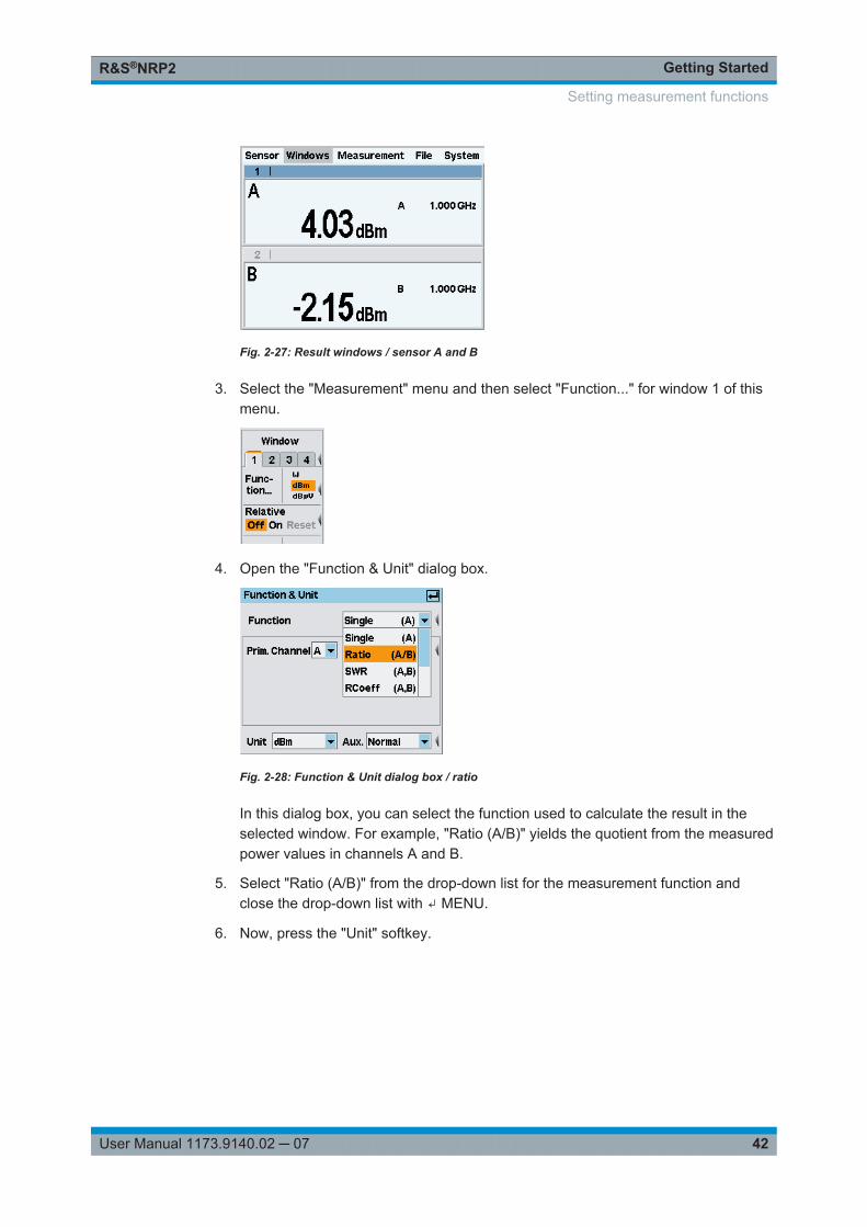
Getting StartedR&S®NRP2
42User Manual 1173.9140.02 ─ 07
Fig. 2-27: Result windows / sensor A and B
3. Select the "Measurement" menu and then select "Function..." for window 1 of thismenu.
4. Open the "Function & Unit" dialog box.
Fig. 2-28: Function & Unit dialog box / ratio
In this dialog box, you can select the function used to calculate the result in theselected window. For example, "Ratio (A/B)" yields the quotient from the measuredpower values in channels A and B.
5. Select "Ratio (A/B)" from the drop-down list for the measurement function andclose the drop-down list with ↵ MENU.
6. Now, press the "Unit" softkey.
Setting measurement functions
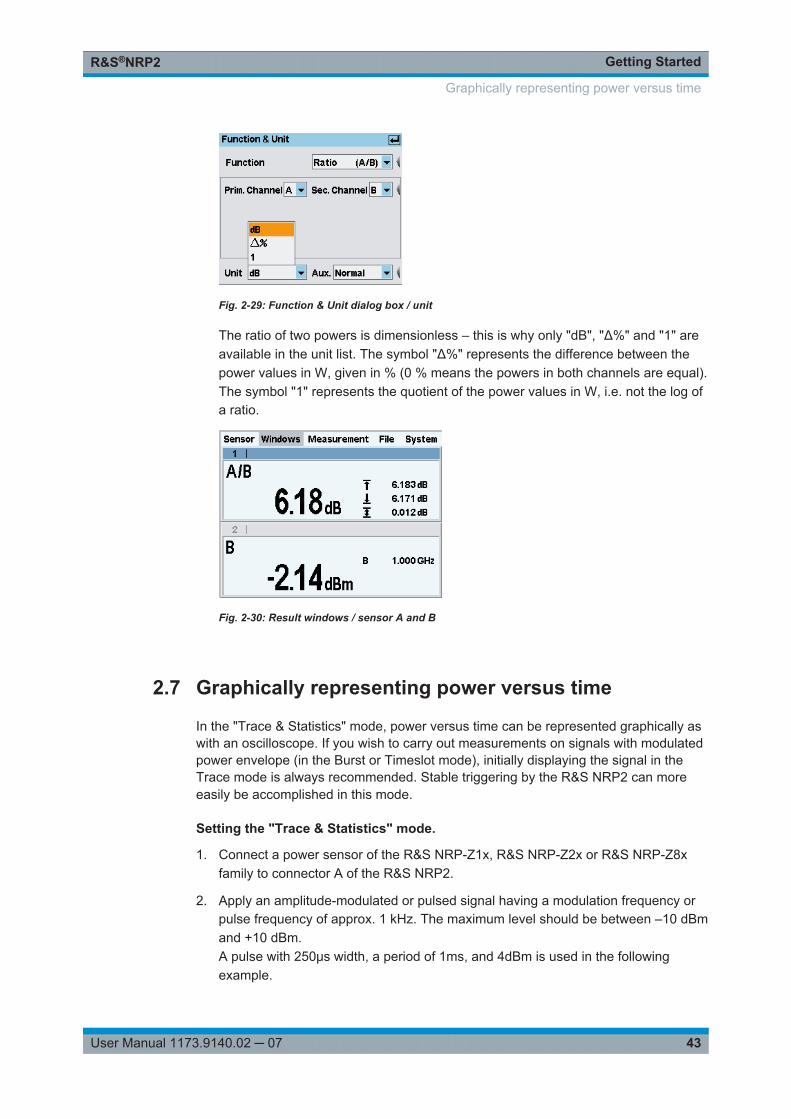
Getting StartedR&S®NRP2
43User Manual 1173.9140.02 ─ 07
Fig. 2-29: Function & Unit dialog box / unit
The ratio of two powers is dimensionless – this is why only "dB", "Δ%" and "1" areavailable in the unit list. The symbol "Δ%" represents the difference between thepower values in W, given in % (0 % means the powers in both channels are equal).The symbol "1" represents the quotient of the power values in W, i.e. not the log ofa ratio.
Fig. 2-30: Result windows / sensor A and B
2.7 Graphically representing power versus time
In the "Trace & Statistics" mode, power versus time can be represented graphically aswith an oscilloscope. If you wish to carry out measurements on signals with modulatedpower envelope (in the Burst or Timeslot mode), initially displaying the signal in theTrace mode is always recommended. Stable triggering by the R&S NRP2 can moreeasily be accomplished in this mode.
Setting the "Trace & Statistics" mode.
1. Connect a power sensor of the R&S NRP-Z1x, R&S NRP-Z2x or R&S NRP-Z8xfamily to connector A of the R&S NRP2.
2. Apply an amplitude-modulated or pulsed signal having a modulation frequency orpulse frequency of approx. 1 kHz. The maximum level should be between –10 dBmand +10 dBm.A pulse with 250μs width, a period of 1ms, and 4dBm is used in the followingexample.
Graphically representing power versus time
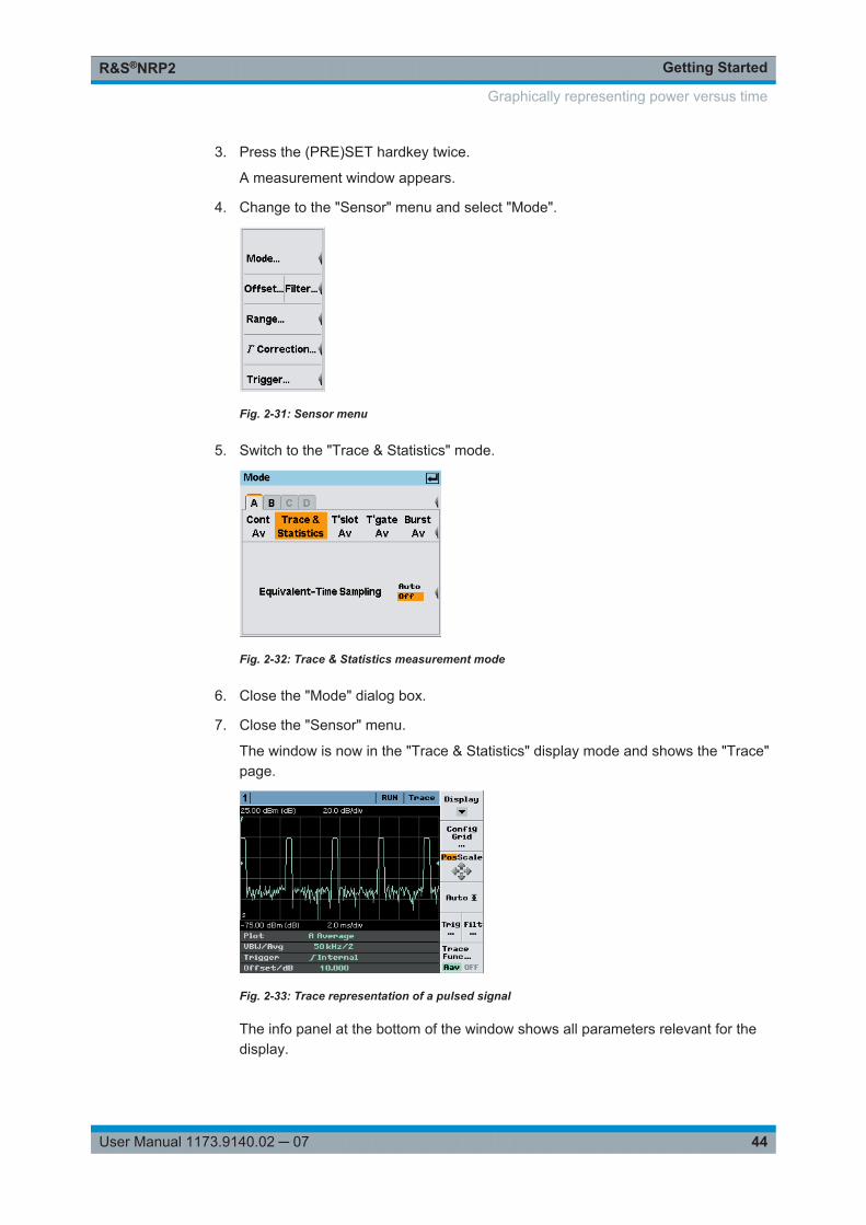
Getting StartedR&S®NRP2
44User Manual 1173.9140.02 ─ 07
3. Press the (PRE)SET hardkey twice.
A measurement window appears.
4. Change to the "Sensor" menu and select "Mode".
Fig. 2-31: Sensor menu
5. Switch to the "Trace & Statistics" mode.
Fig. 2-32: Trace & Statistics measurement mode
6. Close the "Mode" dialog box.
7. Close the "Sensor" menu.
The window is now in the "Trace & Statistics" display mode and shows the "Trace"page.
Fig. 2-33: Trace representation of a pulsed signal
The info panel at the bottom of the window shows all parameters relevant for thedisplay.
Graphically representing power versus time
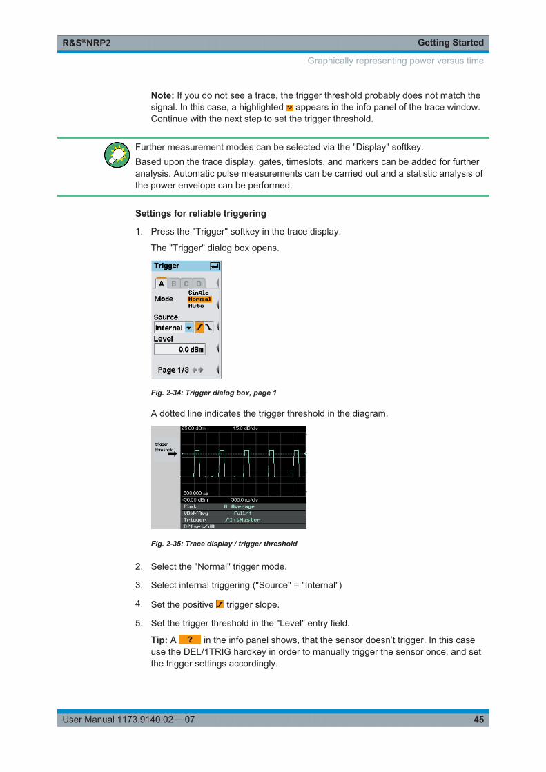
Getting StartedR&S®NRP2
45User Manual 1173.9140.02 ─ 07
Note: If you do not see a trace, the trigger threshold probably does not match thesignal. In this case, a highlighted appears in the info panel of the trace window.Continue with the next step to set the trigger threshold.
Further measurement modes can be selected via the "Display" softkey.Based upon the trace display, gates, timeslots, and markers can be added for furtheranalysis. Automatic pulse measurements can be carried out and a statistic analysis ofthe power envelope can be performed.
Settings for reliable triggering
1. Press the "Trigger" softkey in the trace display.
The "Trigger" dialog box opens.
Fig. 2-34: Trigger dialog box, page 1
A dotted line indicates the trigger threshold in the diagram.
Fig. 2-35: Trace display / trigger threshold
2. Select the "Normal" trigger mode.
3. Select internal triggering ("Source" = "Internal")
4. Set the positive trigger slope.
5. Set the trigger threshold in the "Level" entry field.
Tip: A in the info panel shows, that the sensor doesn’t trigger. In this caseuse the DEL/1TRIG hardkey in order to manually trigger the sensor once, and setthe trigger settings accordingly.
Graphically representing power versus time
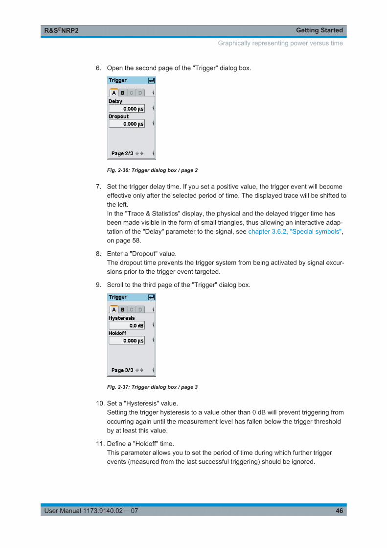
Getting StartedR&S®NRP2
46User Manual 1173.9140.02 ─ 07
6. Open the second page of the "Trigger" dialog box.
Fig. 2-36: Trigger dialog box / page 2
7. Set the trigger delay time. If you set a positive value, the trigger event will becomeeffective only after the selected period of time. The displayed trace will be shifted tothe left.In the "Trace & Statistics" display, the physical and the delayed trigger time hasbeen made visible in the form of small triangles, thus allowing an interactive adap-tation of the "Delay" parameter to the signal, see chapter 3.6.2, "Special symbols",on page 58.
8. Enter a "Dropout" value.The dropout time prevents the trigger system from being activated by signal excur-sions prior to the trigger event targeted.
9. Scroll to the third page of the "Trigger" dialog box.
Fig. 2-37: Trigger dialog box / page 3
10. Set a "Hysteresis" value.Setting the trigger hysteresis to a value other than 0 dB will prevent triggering fromoccurring again until the measurement level has fallen below the trigger thresholdby at least this value.
11. Define a "Holdoff" time.This parameter allows you to set the period of time during which further triggerevents (measured from the last successful triggering) should be ignored.
Graphically representing power versus time
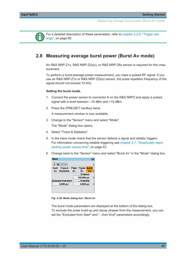
Getting StartedR&S®NRP2
47User Manual 1173.9140.02 ─ 07
For a detailed description of these parameters, refer to chapter 4.2.6, "Trigger set-tings", on page 85.
2.8 Measuring average burst power (Burst Av mode)
An R&S NRP-Z1x, R&S NRP-Z2x(x), or R&S NRP-Z8x sensor is required for this mea-surement.
To perform a burst-average power-measurement, you need a pulsed RF signal. If youuse an R&S NRP-Z1x or R&S NRP-Z2x(x) sensor, the pulse repetition frequency of thesignal should not exceed 10 kHz.
Setting the burst mode.
1. Connect the power sensor to connector A on the R&S NRP2 and apply a pulsedsignal with a level between –10 dBm and +10 dBm.
2. Press the (PRE)SET hardkey twice.
A measurement window is now available.
3. Change to the "Sensor" menu and select "Mode".
The "Mode" dialog box opens.
4. Select "Trace & Statistics".
5. In the trace mode check that the sensor detects a signal and reliably triggers.For information concerning reliable triggering see chapter 2.7, "Graphically repre-senting power versus time", on page 43.
6. Change back to the "Sensor" menu and select "Burst Av" in the "Mode" dialog box.
Fig. 2-38: Mode dialog box / Burst Av
The burst mode parameters are displayed at the bottom of the dialog box.To exclude the pulse build-up and decay phases from the measurement, you canset the "Excluded from Start" and "...from End" parameters accordingly.
Measuring average burst power (Burst Av mode)
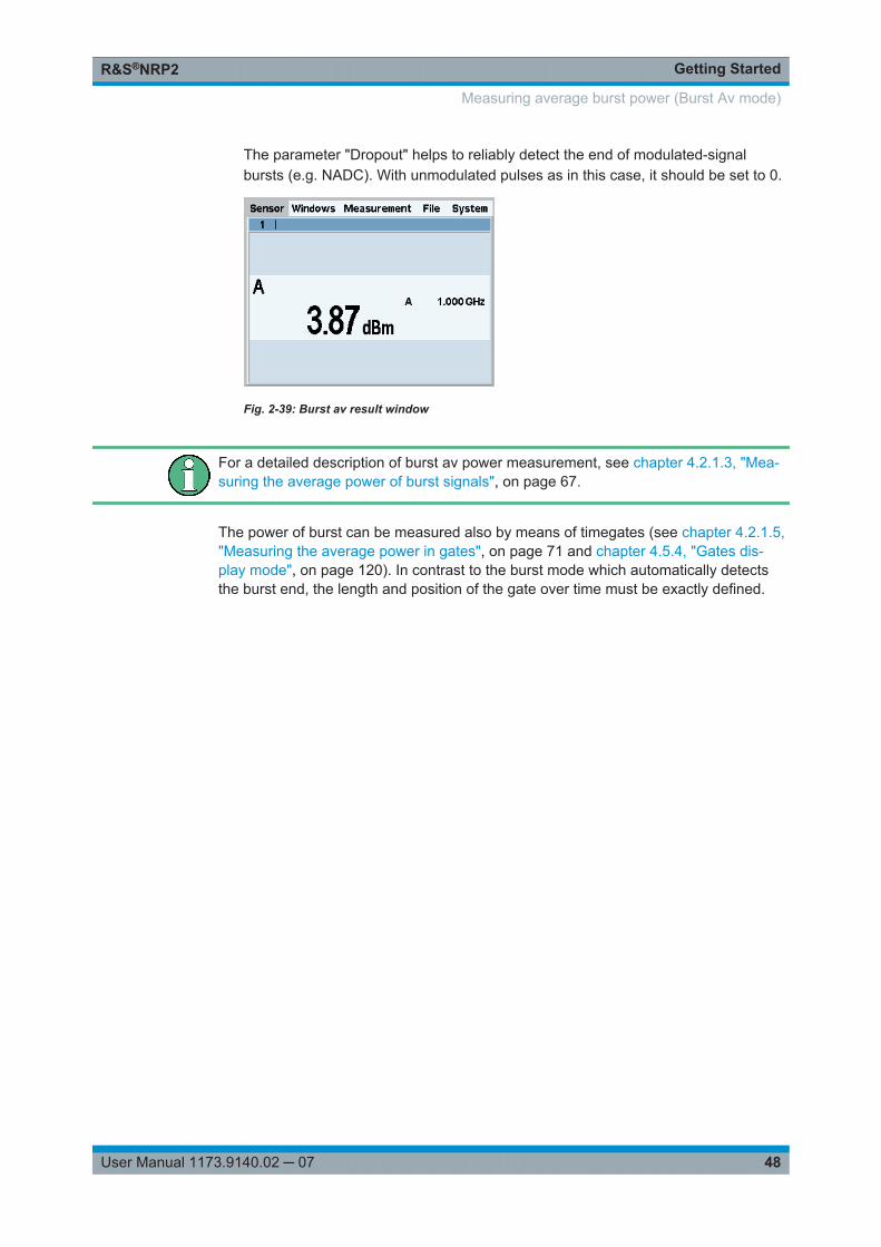
Getting StartedR&S®NRP2
48User Manual 1173.9140.02 ─ 07
The parameter "Dropout" helps to reliably detect the end of modulated-signalbursts (e.g. NADC). With unmodulated pulses as in this case, it should be set to 0.
Fig. 2-39: Burst av result window
For a detailed description of burst av power measurement, see chapter 4.2.1.3, "Mea-suring the average power of burst signals", on page 67.
The power of burst can be measured also by means of timegates (see chapter 4.2.1.5,"Measuring the average power in gates", on page 71 and chapter 4.5.4, "Gates dis-play mode", on page 120). In contrast to the burst mode which automatically detectsthe burst end, the length and position of the gate over time must be exactly defined.
Measuring average burst power (Burst Av mode)
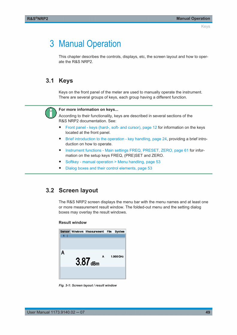
Manual OperationR&S®NRP2
49User Manual 1173.9140.02 ─ 07
3 Manual OperationThis chapter describes the controls, displays, etc, the screen layout and how to oper-ate the R&S NRP2.
3.1 Keys
Keys on the front panel of the meter are used to manually operate the instrument.There are several groups of keys, each group having a different function.
For more information on keys...According to their functionality, keys are described in several sections of theR&S NRP2 documentation. See:● Front panel - keys (hard-, soft- and cursor), page 12 for information on the keys
located at the front panel.● Brief introduction to the operation - key handling, page 24, providing a brief intro-
duction on how to operate.● Instrument functions - Main settings FREQ, PRESET, ZERO, page 61 for infor-
mation on the setup keys FREQ, (PRE)SET and ZERO.● Softkey - manual operation > Menu handling, page 53● Dialog boxes and their control elements, page 53
3.2 Screen layout
The R&S NRP2 screen displays the menu bar with the menu names and at least oneor more measurement result window. The folded-out menu and the setting dialogboxes may overlay the result windows.
Result window
Fig. 3-1: Screen layout / result window
Keys
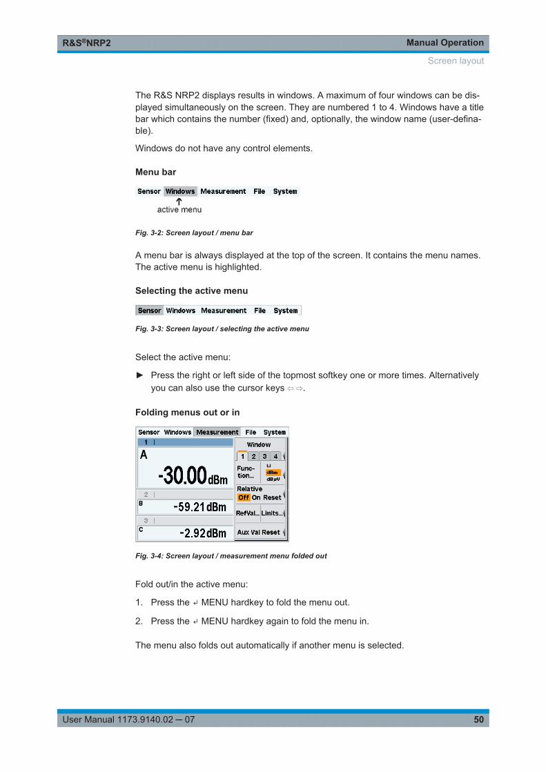
Manual OperationR&S®NRP2
50User Manual 1173.9140.02 ─ 07
The R&S NRP2 displays results in windows. A maximum of four windows can be dis-played simultaneously on the screen. They are numbered 1 to 4. Windows have a titlebar which contains the number (fixed) and, optionally, the window name (user-defina-ble).
Windows do not have any control elements.
Menu bar
Fig. 3-2: Screen layout / menu bar
A menu bar is always displayed at the top of the screen. It contains the menu names.The active menu is highlighted.
Selecting the active menu
Fig. 3-3: Screen layout / selecting the active menu
Select the active menu:
► Press the right or left side of the topmost softkey one or more times. Alternativelyyou can also use the cursor keys ⇦ ⇨.
Folding menus out or in
Fig. 3-4: Screen layout / measurement menu folded out
Fold out/in the active menu:
1. Press the ↵ MENU hardkey to fold the menu out.
2. Press the ↵ MENU hardkey again to fold the menu in.
The menu also folds out automatically if another menu is selected.
Screen layout
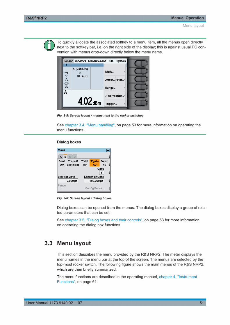
Manual OperationR&S®NRP2
51User Manual 1173.9140.02 ─ 07
To quickly allocate the associated softkey to a menu item, all the menus open directlynext to the softkey bar, i.e. on the right side of the display; this is against usual PC con-vention with menus drop-down directly below the menu name.
Fig. 3-5: Screen layout / menus next to the rocker switches
See chapter 3.4, "Menu handling", on page 53 for more information on operating themenu functions.
Dialog boxes
Fig. 3-6: Screen layout / dialog boxes
Dialog boxes can be opened from the menus. The dialog boxes display a group of rela-ted parameters that can be set.
See chapter 3.5, "Dialog boxes and their controls", on page 53 for more informationon operating the dialog box functions.
3.3 Menu layout
This section describes the menu provided by the R&S NRP2. The meter displays themenu names in the menu bar at the top of the screen. The menus are selected by thetop-most rocker switch. The following figure shows the main menus of the R&S NRP2,which are then briefly summarized.
The menu functions are described in the operating manual, chapter 4, "InstrumentFunctions", on page 61.
Menu layout
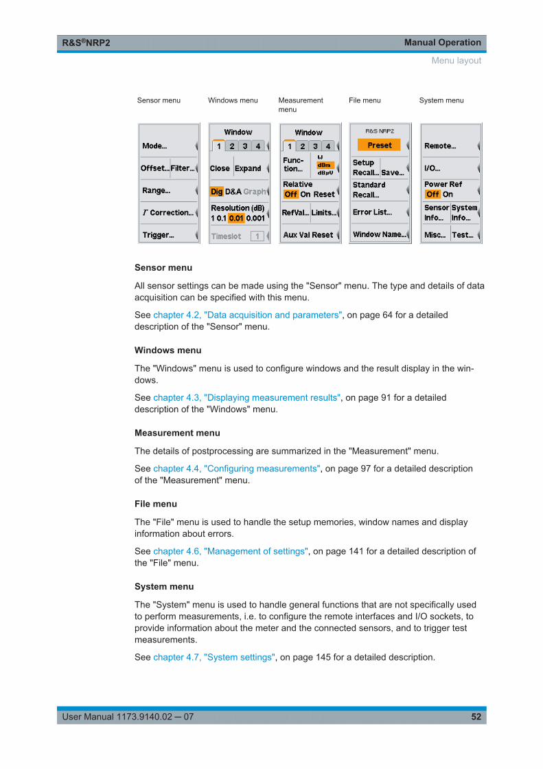
Manual OperationR&S®NRP2
52User Manual 1173.9140.02 ─ 07
Sensor menu Windows menu Measurementmenu
File menu System menu
Sensor menu
All sensor settings can be made using the "Sensor" menu. The type and details of dataacquisition can be specified with this menu.
See chapter 4.2, "Data acquisition and parameters", on page 64 for a detaileddescription of the "Sensor" menu.
Windows menu
The "Windows" menu is used to configure windows and the result display in the win-dows.
See chapter 4.3, "Displaying measurement results", on page 91 for a detaileddescription of the "Windows" menu.
Measurement menu
The details of postprocessing are summarized in the "Measurement" menu.
See chapter 4.4, "Configuring measurements", on page 97 for a detailed descriptionof the "Measurement" menu.
File menu
The "File" menu is used to handle the setup memories, window names and displayinformation about errors.
See chapter 4.6, "Management of settings", on page 141 for a detailed description ofthe "File" menu.
System menu
The "System" menu is used to handle general functions that are not specifically usedto perform measurements, i.e. to configure the remote interfaces and I/O sockets, toprovide information about the meter and the connected sensors, and to trigger testmeasurements.
See chapter 4.7, "System settings", on page 145 for a detailed description.
Menu layout

Manual OperationR&S®NRP2
53User Manual 1173.9140.02 ─ 07
3.4 Menu handling
The menus can contain up to eight menu items which are used to perform an action,open a dialog box or set a parameter.
Perform an action
If the menu contains only one or two descriptive terms, an action is performed directly.
Use a hardkey to perform an action
If the name of the action to be performed is shown in a wide orange field, you can startthe action by pressing the hardkey of the same name, e.g. (PRE)SET in this case.
Open a dialog box
If a menu item is followed by three dots “…”, it can be used to open a dialog box to seta variety of parameters.
Set parameters
Parameter setting options are provided in the menu. The currently selected option ishighlighted in orange. Select the option by pressing the left or right side of the associ-ated rocker switch.
Use of softkeys with dual assignments
Some softkeys are assigned two menu items. One is selected by pressing the left-handside of the rocker switch, the other, the right-hand side.
The two menu items are separated by a vertical line.
3.5 Dialog boxes and their controls
Dialog boxes contain check boxes, option fields, editing fields and drop-down lists ascontrol elements. They are activated using the appropriate rocker switch to their right.If two control elements are positioned side by side, the element on the left is operatedwith the left-hand side of the rocker switch and the element on the right with the right-hand side of the rocker switch.
Menu handling
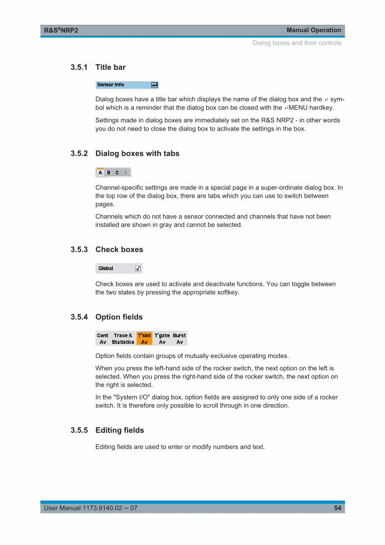
Manual OperationR&S®NRP2
54User Manual 1173.9140.02 ─ 07
3.5.1 Title bar
Dialog boxes have a title bar which displays the name of the dialog box and the ↵ sym-bol which is a reminder that the dialog box can be closed with the ↵MENU hardkey.
Settings made in dialog boxes are immediately set on the R&S NRP2 - in other wordsyou do not need to close the dialog box to activate the settings in the box.
3.5.2 Dialog boxes with tabs
Channel-specific settings are made in a special page in a super-ordinate dialog box. Inthe top row of the dialog box, there are tabs which you can use to switch betweenpages.
Channels which do not have a sensor connected and channels that have not beeninstalled are shown in gray and cannot be selected.
3.5.3 Check boxes
Check boxes are used to activate and deactivate functions. You can toggle betweenthe two states by pressing the appropriate softkey.
3.5.4 Option fields
Option fields contain groups of mutually exclusive operating modes.
When you press the left-hand side of the rocker switch, the next option on the left isselected. When you press the right-hand side of the rocker switch, the next option onthe right is selected.
In the "System I/O" dialog box, option fields are assigned to only one side of a rockerswitch. It is therefore only possible to scroll through in one direction.
3.5.5 Editing fields
Editing fields are used to enter or modify numbers and text.
Dialog boxes and their controls
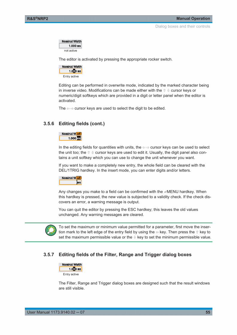
Manual OperationR&S®NRP2
55User Manual 1173.9140.02 ─ 07
The editor is activated by pressing the appropriate rocker switch.
Editing can be performed in overwrite mode, indicated by the marked character beingin inverse video. Modifications can be made either with the ⇧ ⇩ cursor keys ornumeric/digit softkeys which are provided in a digit or letter panel when the editor isactivated.
The ⇦ ⇨ cursor keys are used to select the digit to be edited.
3.5.6 Editing fields (cont.)
In the editing fields for quantities with units, the ⇦ ⇨ cursor keys can be used to selectthe unit too; the ⇧ ⇩ cursor keys are used to edit it. Usually, the digit panel also con-tains a unit softkey which you can use to change the unit whenever you want.
If you want to make a completely new entry, the whole field can be cleared with theDEL/1TRIG hardkey. In the insert mode, you can enter digits and/or letters.
Any changes you make to a field can be confirmed with the ↵MENU hardkey. Whenthis hardkey is pressed, the new value is subjected to a validity check. If the check dis-covers an error, a warning message is output.
You can quit the editor by pressing the ESC hardkey; this leaves the old valuesunchanged. Any warning messages are cleared.
To set the maximum or minimum value permitted for a parameter, first move the inser-tion mark to the left edge of the entry field by using the ⇦ key. Then press the ⇧ key toset the maximum permissible value or the ⇩ key to set the minimum permissible value.
3.5.7 Editing fields of the Filter, Range and Trigger dialog boxes
The Filter, Range and Trigger dialog boxes are designed such that the result windowsare still visible.
Dialog boxes and their controls
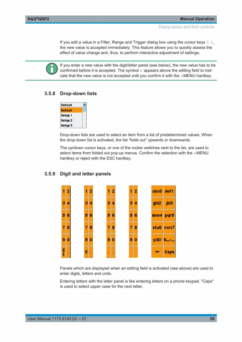
Manual OperationR&S®NRP2
56User Manual 1173.9140.02 ─ 07
If you edit a value in a Filter, Range and Trigger dialog box using the cursor keys ⇧ ⇩,the new value is accepted immediately. This feature allows you to quickly assess theeffect of value change and, thus, to perform interactive adjustment of settings.
If you enter a new value with the digit/letter panel (see below), the new value has to beconfirmed before it is accepted. The symbol ↵ appears above the editing field to indi-cate that the new value is not accepted until you confirm it with the ↵MENU hardkey.
3.5.8 Drop-down lists
Drop-down lists are used to select an item from a list of predetermined values. Whenthe drop-down list is activated, the list “folds out” upwards or downwards.
The up/down cursor keys, or one of the rocker switches next to the list, are used toselect items from folded out pop-up menus. Confirm the selection with the ↵MENUhardkey or reject with the ESC hardkey.
3.5.9 Digit and letter panels
Panels which are displayed when an editing field is activated (see above) are used toenter digits, letters and units.
Entering letters with the letter panel is like entering letters on a phone keypad. "Caps"is used to select upper case for the next letter.
Dialog boxes and their controls
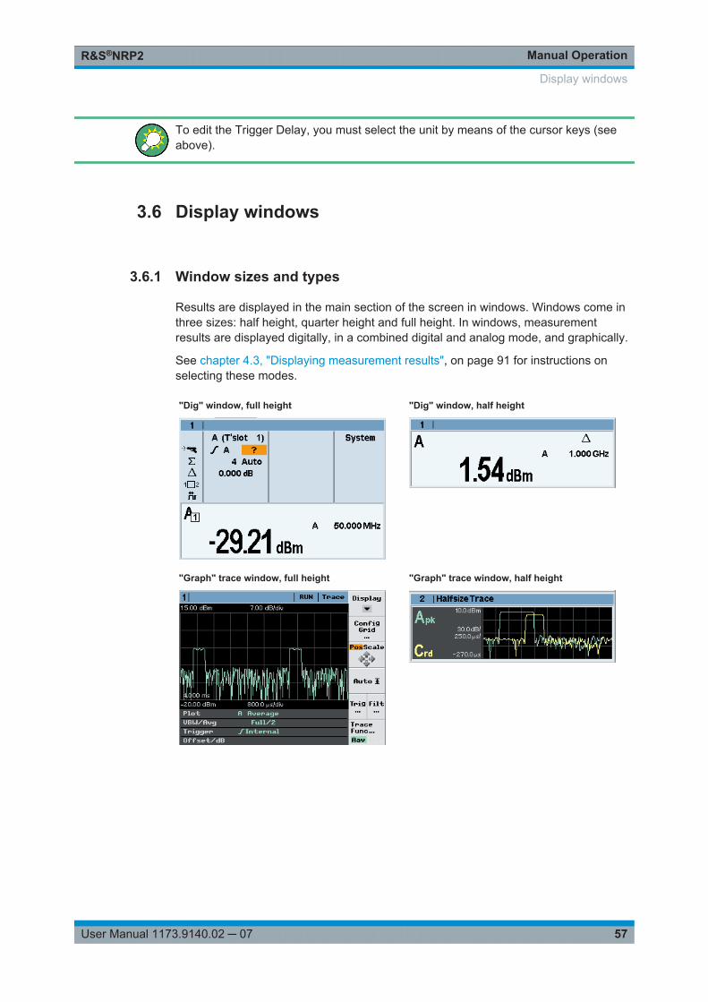
Manual OperationR&S®NRP2
57User Manual 1173.9140.02 ─ 07
To edit the Trigger Delay, you must select the unit by means of the cursor keys (seeabove).
3.6 Display windows
3.6.1 Window sizes and types
Results are displayed in the main section of the screen in windows. Windows come inthree sizes: half height, quarter height and full height. In windows, measurementresults are displayed digitally, in a combined digital and analog mode, and graphically.
See chapter 4.3, "Displaying measurement results", on page 91 for instructions onselecting these modes.
"Dig" window, full height "Dig" window, half height
"Graph" trace window, full height "Graph" trace window, half height
Display windows
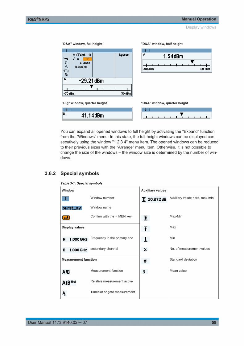
Manual OperationR&S®NRP2
58User Manual 1173.9140.02 ─ 07
"D&A" window, full height "D&A" window, half height
"Dig" window, quarter height "D&A" window, quarter height
You can expand all opened windows to full height by activating the "Expand" functionfrom the "Windows" menu. In this state, the full-height windows can be displayed con-secutively using the window "1 2 3 4" menu item. The opened windows can be reducedto their previous sizes with the "Arrange" menu item. Otherwise, it is not possible tochange the size of the windows – the window size is determined by the number of win-dows.
3.6.2 Special symbols
Table 3-1: Special symbols
Window Auxiliary values
Window number Auxiliary value; here, max-min
Window name
Confirm with the ↵ MEN key Max-Min
Display values Max
Frequency in the primary and Min
secondary channel No. of measurement values
Measurement function Standard deviation
Measurement function Mean value
Relative measurement active
Timeslot or gate measurement
Display windows
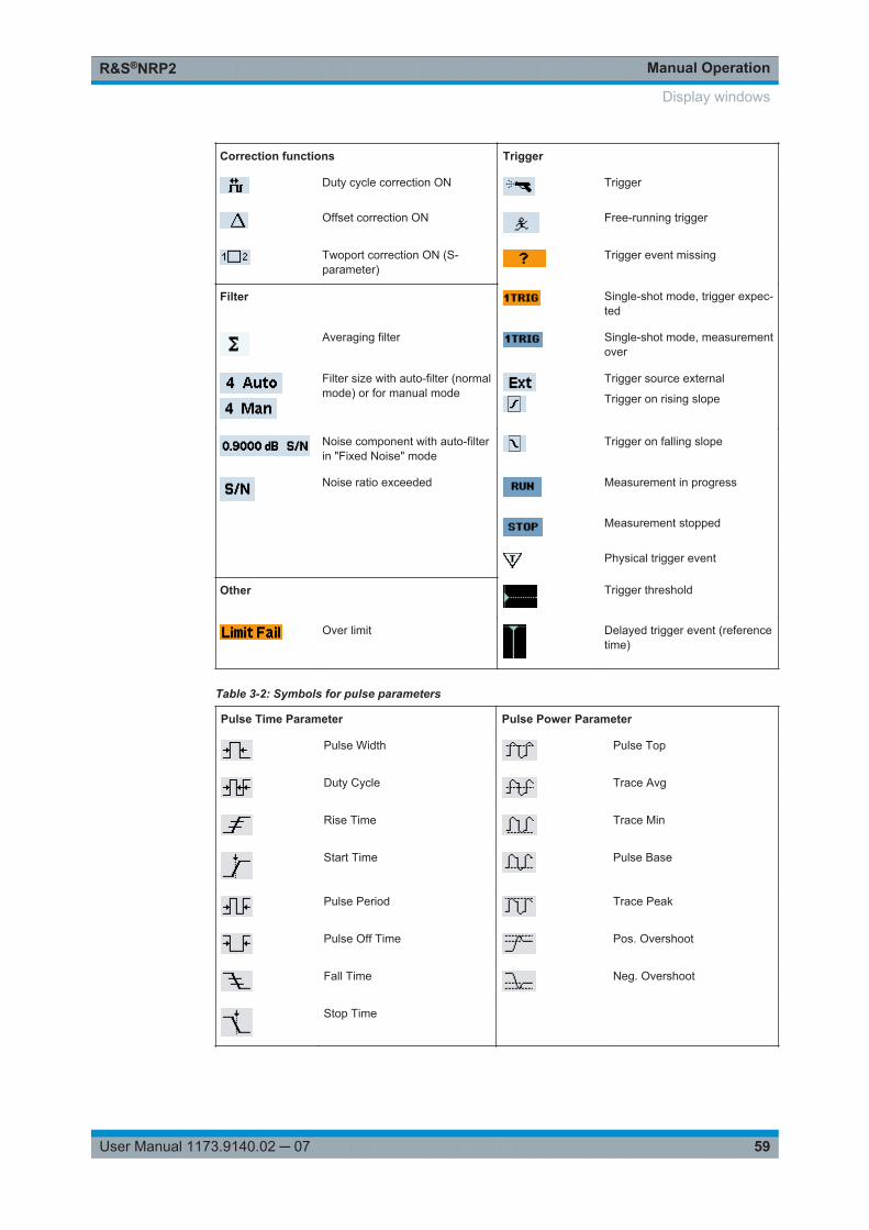
Manual OperationR&S®NRP2
59User Manual 1173.9140.02 ─ 07
Correction functions Trigger
Duty cycle correction ON Trigger
Offset correction ON Free-running trigger
Twoport correction ON (S-parameter)
Trigger event missing
Filter Single-shot mode, trigger expec-ted
Averaging filter Single-shot mode, measurementover
Filter size with auto-filter (normalmode) or for manual mode
Trigger source external
Trigger on rising slope
Noise component with auto-filterin "Fixed Noise" mode
Trigger on falling slope
Noise ratio exceeded Measurement in progress
Measurement stopped
Physical trigger event
Other Trigger threshold
Over limit Delayed trigger event (referencetime)
Table 3-2: Symbols for pulse parameters
Pulse Time Parameter Pulse Power Parameter
Pulse Width Pulse Top
Duty Cycle Trace Avg
Rise Time Trace Min
Start Time Pulse Base
Pulse Period Trace Peak
Pulse Off Time Pos. Overshoot
Fall Time Neg. Overshoot
Stop Time
Display windows
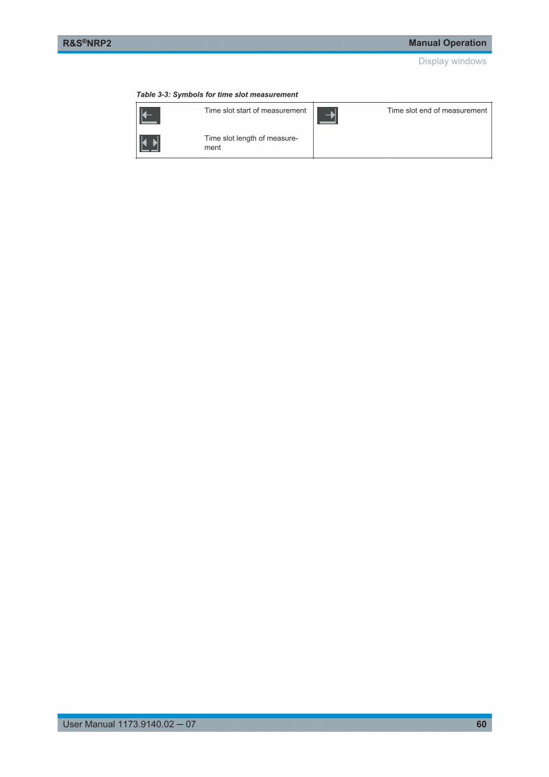
Manual OperationR&S®NRP2
60User Manual 1173.9140.02 ─ 07
Table 3-3: Symbols for time slot measurement
Time slot start of measurement Time slot end of measurement
Time slot length of measure-ment
Display windows
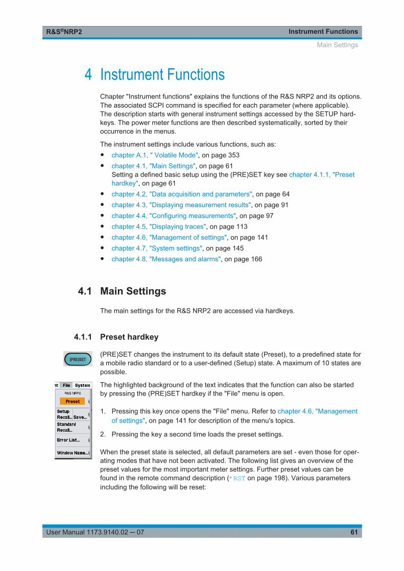
Instrument FunctionsR&S®NRP2
61User Manual 1173.9140.02 ─ 07
4 Instrument FunctionsChapter "Instrument functions" explains the functions of the R&S NRP2 and its options.The associated SCPI command is specified for each parameter (where applicable).The description starts with general instrument settings accessed by the SETUP hard-keys. The power meter functions are then described systematically, sorted by theiroccurrence in the menus.
The instrument settings include various functions, such as:● chapter A.1, " Volatile Mode", on page 353● chapter 4.1, "Main Settings", on page 61
Setting a defined basic setup using the (PRE)SET key see chapter 4.1.1, "Presethardkey", on page 61
● chapter 4.2, "Data acquisition and parameters", on page 64● chapter 4.3, "Displaying measurement results", on page 91● chapter 4.4, "Configuring measurements", on page 97● chapter 4.5, "Displaying traces", on page 113● chapter 4.6, "Management of settings", on page 141● chapter 4.7, "System settings", on page 145● chapter 4.8, "Messages and alarms", on page 166
4.1 Main Settings
The main settings for the R&S NRP2 are accessed via hardkeys.
4.1.1 Preset hardkey
(PRE)SET changes the instrument to its default state (Preset), to a predefined state fora mobile radio standard or to a user-defined (Setup) state. A maximum of 10 states arepossible.
The highlighted background of the text indicates that the function can also be startedby pressing the (PRE)SET hardkey if the "File" menu is open.
1. Pressing this key once opens the "File" menu. Refer to chapter 4.6, "Managementof settings", on page 141 for description of the menu's topics.
2. Pressing the key a second time loads the preset settings.
When the preset state is selected, all default parameters are set - even those for oper-ating modes that have not been activated. The following list gives an overview of thepreset values for the most important meter settings. Further preset values can befound in the remote command description (*RST on page 198). Various parametersincluding the following will be reset:
Main Settings
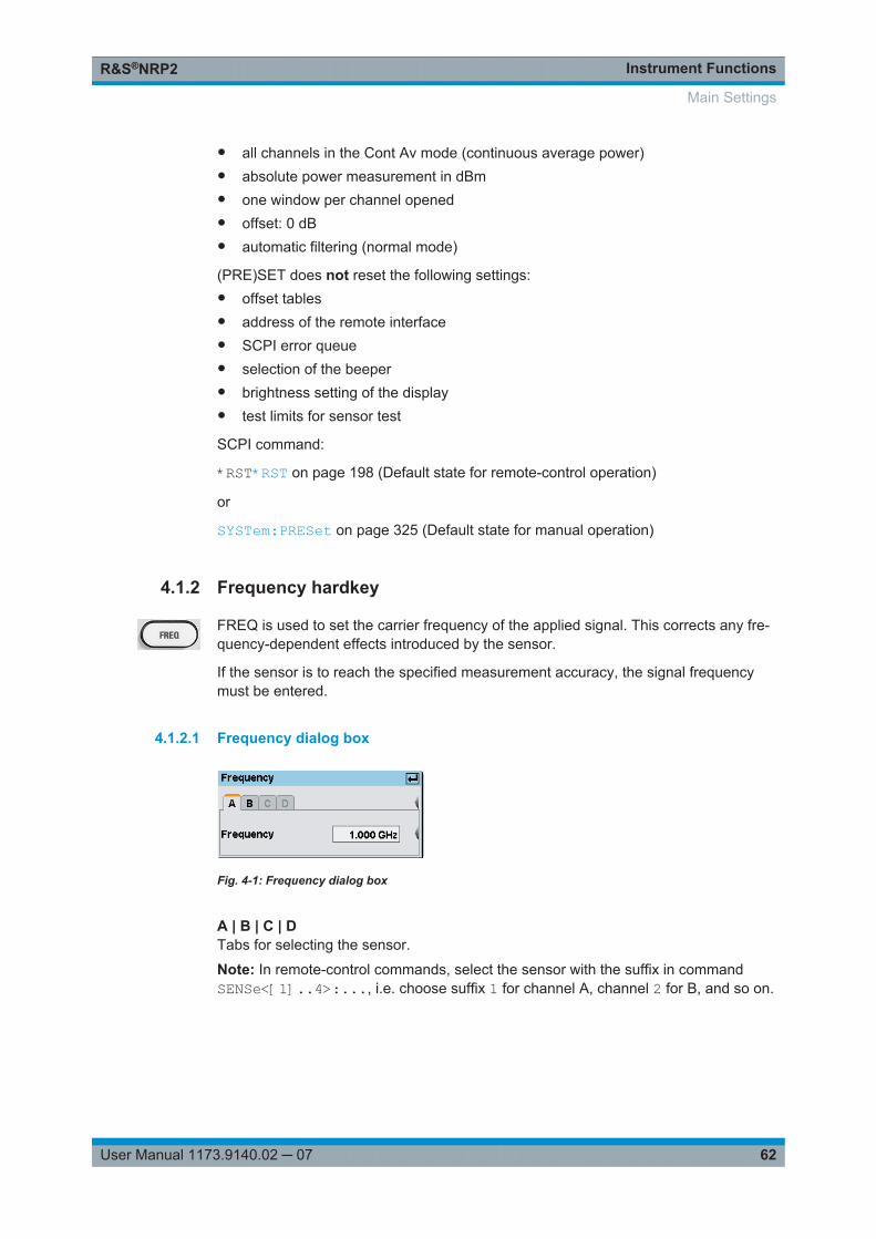
Instrument FunctionsR&S®NRP2
62User Manual 1173.9140.02 ─ 07
● all channels in the Cont Av mode (continuous average power)● absolute power measurement in dBm● one window per channel opened● offset: 0 dB● automatic filtering (normal mode)
(PRE)SET does not reset the following settings:● offset tables● address of the remote interface● SCPI error queue● selection of the beeper● brightness setting of the display● test limits for sensor test
SCPI command:
*RST*RST on page 198 (Default state for remote-control operation)
or
SYSTem:PRESet on page 325 (Default state for manual operation)
4.1.2 Frequency hardkey
FREQ is used to set the carrier frequency of the applied signal. This corrects any fre-quency-dependent effects introduced by the sensor.
If the sensor is to reach the specified measurement accuracy, the signal frequencymust be entered.
4.1.2.1 Frequency dialog box
Fig. 4-1: Frequency dialog box
A | B | C | DTabs for selecting the sensor.
Note: In remote-control commands, select the sensor with the suffix in commandSENSe<[1]..4>:..., i.e. choose suffix 1 for channel A, channel 2 for B, and so on.
Main Settings
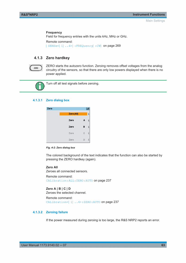
Instrument FunctionsR&S®NRP2
63User Manual 1173.9140.02 ─ 07
FrequencyField for frequency entries with the units kHz, MHz or GHz.
Remote command: [SENSe<[1]..4>]:FREQuency[:CW] on page 269
4.1.3 Zero hardkey
ZERO starts the autozero function. Zeroing removes offset voltages from the analogcircuitry of the sensors, so that there are only low powers displayed when there is nopower applied.
Turn off all test signals before zeroing.
4.1.3.1 Zero dialog box
Fig. 4-2: Zero dialog box
The colored background of the text indicates that the function can also be started bypressing the ZERO hardkey (again).
Zero AllZeroes all connected sensors.
Remote command: CALibration:ALL:ZERO:AUTO on page 237
Zero A | B | C | DZeroes the selected channel.
Remote command: CALibration<[1]..4>:ZERO:AUTO on page 237
4.1.3.2 Zeroing failure
If the power measured during zeroing is too large, the R&S NRP2 reports an error.
Main Settings

Instrument FunctionsR&S®NRP2
64User Manual 1173.9140.02 ─ 07
Fig. 4-3: Zeroing error message
This error is often caused by zeroing without switching off the test signal. If this is notthe cause, the sensor might have a hardware defect.
4.2 Data acquisition and parameters
Depending on the options that have been installed, up to four sensors can be connec-ted to the R&S NRP2. The sensors perform the complete power measurement fromthe acquisition of the RF signal to every aspect of result processing. All importantparameters for configuring data acquisition are therefore entered in the "Sensor" menu.The sensor menu provides access to all parameters concerning sensor settings likemeasuring mode, filter, offset, gamma correction, level range and trigger settings.
The Sensor menu contains the following items:
● Setting the measurement mode, on page 64● Offset correction, on page 76 and Filter/averaging, on page 79● Measurement ranges, on page 83● Effect of the RF source, on page 84● Trigger settings, on page 85● Trigger sequence control, on page 89
Some of the parameters listed above are not available for certain types of sensor.
4.2.1 Setting the measurement mode
The measurement mode is selected and configured in the "Mode" dialog box.
Regarding power measurement modes, find some background information to the fol-lowing topics at the end of this section (see chapter 4.2.1.7, "Background informationon power measurement", on page 72):● "Acquisition interval" on page 72.● "Dropout tolerance" on page 74● "Smoothing modulated signals" on page 73● "Timing diagram of burst signals" on page 74● "Timing diagram of T'Slot Av signals" on page 75
Data acquisition and parameters
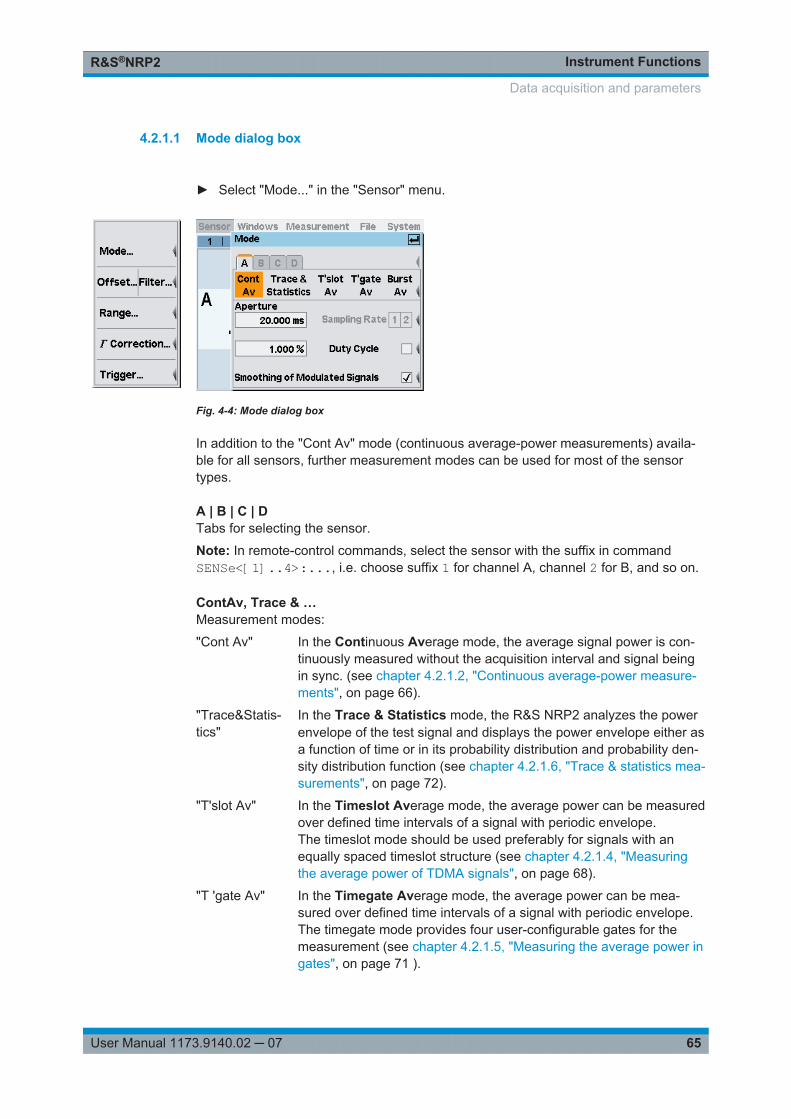
Instrument FunctionsR&S®NRP2
65User Manual 1173.9140.02 ─ 07
4.2.1.1 Mode dialog box
► Select "Mode..." in the "Sensor" menu.
Fig. 4-4: Mode dialog box
In addition to the "Cont Av" mode (continuous average-power measurements) availa-ble for all sensors, further measurement modes can be used for most of the sensortypes.
A | B | C | DTabs for selecting the sensor.
Note: In remote-control commands, select the sensor with the suffix in commandSENSe<[1]..4>:..., i.e. choose suffix 1 for channel A, channel 2 for B, and so on.
ContAv, Trace & …Measurement modes:
"Cont Av" In the Continuous Average mode, the average signal power is con-tinuously measured without the acquisition interval and signal beingin sync. (see chapter 4.2.1.2, "Continuous average-power measure-ments", on page 66).
"Trace&Statis-tics"
In the Trace & Statistics mode, the R&S NRP2 analyzes the powerenvelope of the test signal and displays the power envelope either asa function of time or in its probability distribution and probability den-sity distribution function (see chapter 4.2.1.6, "Trace & statistics mea-surements", on page 72).
"T'slot Av" In the Timeslot Average mode, the average power can be measuredover defined time intervals of a signal with periodic envelope.The timeslot mode should be used preferably for signals with anequally spaced timeslot structure (see chapter 4.2.1.4, "Measuringthe average power of TDMA signals", on page 68).
"T 'gate Av" In the Timegate Average mode, the average power can be mea-sured over defined time intervals of a signal with periodic envelope.The timegate mode provides four user-configurable gates for themeasurement (see chapter 4.2.1.5, "Measuring the average power ingates", on page 71 ).
Data acquisition and parameters
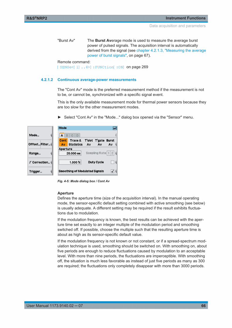
Instrument FunctionsR&S®NRP2
66User Manual 1173.9140.02 ─ 07
"Burst Av" The Burst Average mode is used to measure the average burstpower of pulsed signals. The acquisition interval is automaticallyderived from the signal (see chapter 4.2.1.3, "Measuring the averagepower of burst signals", on page 67).
Remote command: [SENSe<[1]..4>]:FUNCtion[:ON] on page 269
4.2.1.2 Continuous average-power measurements
The "Cont Av" mode is the preferred measurement method if the measurement is notto be, or cannot be, synchronized with a specific signal event.
This is the only available measurement mode for thermal power sensors because theyare too slow for the other measurement modes.
► Select "Cont Av" in the "Mode..." dialog box opened via the "Sensor" menu.
Fig. 4-5: Mode dialog box / Cont Av
ApertureDefines the aperture time (size of the acquisition interval). In the manual operatingmode, the sensor-specific default setting combined with active smoothing (see below)is usually adequate. A different setting may be required if the result exhibits fluctua-tions due to modulation.
If the modulation frequency is known, the best results can be achieved with the aper-ture time set exactly to an integer multiple of the modulation period and smoothingswitched off. If possible, choose the multiple such that the resulting aperture time isabout as high as its sensor-specific default value.
If the modulation frequency is not known or not constant, or if a spread-spectrum mod-ulation technique is used, smoothing should be switched on. With smoothing on, aboutfive periods are enough to reduce fluctuations caused by modulation to an acceptablelevel. With more than nine periods, the fluctuations are imperceptible. With smoothingoff, the situation is much less favorable as instead of just five periods as many as 300are required; the fluctuations only completely disappear with more than 3000 periods.
Data acquisition and parameters
Instrument FunctionsR&S®NRP2
67User Manual 1173.9140.02 ─ 07
It is not useful to select the aperture time longer than required, since it increases thenoise component of the power sensor (chapter 4.2.1.7, "Background information onpower measurement", on page 72).
Remote command: [SENSe<[1]..4>][:POWer][:AVG]:APERture on page 272
Sampling rateSets the sampling rate. With the multipath power sensors R&S NRP-Z11/21/22/23/24/28/31/32, the sampling rate can be set to two different values to pre-vent aliasing effects for particular types of modulation signal. Aliasing can occurbecause the sampling frequency is located within the video bandwidth, which meansthat spectral components near the sampling frequency can cause beating effects. Withchanging the sampling rate, the beating effects usually disappear.
Remote command: [SENSe<[1]..4>]:SAMPling on page 279
Duty CycleUsing the duty cycle correction, the average power of RF bursts is calculated from theaverage power of the whole signal. Essentially, the average power of the whole signalis divided by the set duty cycle.
If thermal power sensors or R&S NRP-Z91/98 multipath power sensors are used, thisprocedure is the only way to determine the power of pulsed signals.
If multipath power sensors R&S NRP-Z11/21/22/23/24/28/31/32 are used, this methodmust be employed if the bursts are so short that their power cannot be measured in the"Burst Av" or "Timegate Av" modes.
Remote command: [SENSe<[1]..4>]:CORRection:DCYCle:STATe on page 268[SENSe<[1]..4>]:CORRection:DCYCle[:INPut][:MAGNitude] on page 267
Smoothing of modulated signalsTo reduce result fluctuations caused by modulation, this parameter should always beactivated if the aperture time cannot be exactly adjusted to the modulation period. If theaperture time is only 5 to 9 times larger than a modulation period, the display fluctua-tions are sufficiently reduced. With smoothing off, 300 to 3000 periods would berequired to obtain the same effect ("Aperture" on page 66).
Remote command: [SENSe<[1]..4>][:POWer][:AVG]:SMOothing:STATe on page 273
4.2.1.3 Measuring the average power of burst signals
The "Burst Av" mode is the simplest way of measuring the average burst power. It isavailable with the multipath power sensors (R&S NRP-Z11/21/22/23/24/28/31/32) andthe R&S NRP-Z8x wideband power sensors.
When this mode is selected, the sensor itself detects the start and end of the burst; noexternal trigger signal is required. The parameter "Dropout" for detecting the fallingedge and the parameters of the trigger menu, see chapter 4.2.6, "Trigger settings",on page 85, are different ways of providing a stable measurement. By using the
Data acquisition and parameters
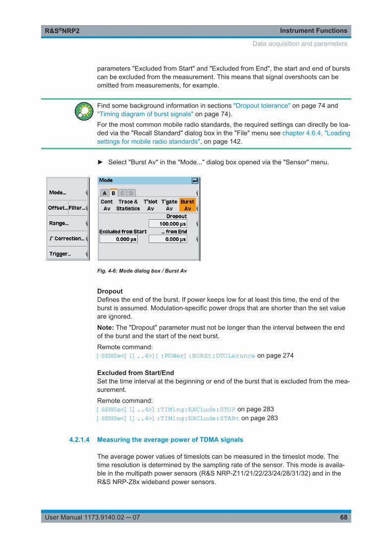
Instrument FunctionsR&S®NRP2
68User Manual 1173.9140.02 ─ 07
parameters "Excluded from Start" and "Excluded from End", the start and end of burstscan be excluded from the measurement. This means that signal overshoots can beomitted from measurements, for example.
Find some background information in sections "Dropout tolerance" on page 74 and"Timing diagram of burst signals" on page 74).For the most common mobile radio standards, the required settings can directly be loa-ded via the "Recall Standard" dialog box in the "File" menu see chapter 4.6.4, "Loadingsettings for mobile radio standards", on page 142.
► Select "Burst Av" in the "Mode..." dialog box opened via the "Sensor" menu.
Fig. 4-6: Mode dialog box / Burst Av
DropoutDefines the end of the burst. If power keeps low for at least this time, the end of theburst is assumed. Modulation-specific power drops that are shorter than the set valueare ignored.
Note: The "Dropout" parameter must not be longer than the interval between the endof the burst and the start of the next burst.
Remote command: [SENSe<[1]..4>][:POWer]:BURSt:DTOLerance on page 274
Excluded from Start/EndSet the time interval at the beginning or end of the burst that is excluded from the mea-surement.
Remote command: [SENSe<[1]..4>]:TIMing:EXCLude:STOP on page 283[SENSe<[1]..4>]:TIMing:EXCLude:STARt on page 283
4.2.1.4 Measuring the average power of TDMA signals
The average power values of timeslots can be measured in the timeslot mode. Thetime resolution is determined by the sampling rate of the sensor. This mode is availa-ble in the multipath power sensors (R&S NRP-Z11/21/22/23/24/28/31/32) and in theR&S NRP-Z8x wideband power sensors.
Data acquisition and parameters
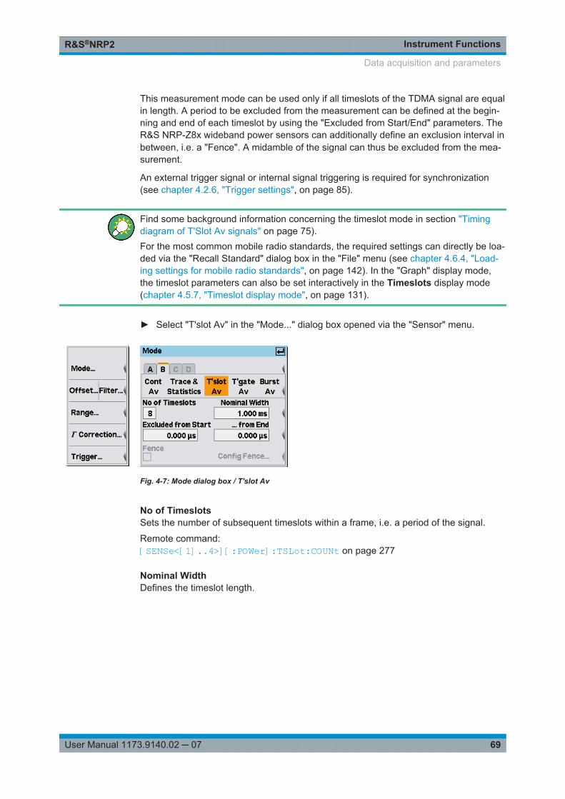
Instrument FunctionsR&S®NRP2
69User Manual 1173.9140.02 ─ 07
This measurement mode can be used only if all timeslots of the TDMA signal are equalin length. A period to be excluded from the measurement can be defined at the begin-ning and end of each timeslot by using the "Excluded from Start/End" parameters. TheR&S NRP-Z8x wideband power sensors can additionally define an exclusion interval inbetween, i.e. a "Fence". A midamble of the signal can thus be excluded from the mea-surement.
An external trigger signal or internal signal triggering is required for synchronization(see chapter 4.2.6, "Trigger settings", on page 85).
Find some background information concerning the timeslot mode in section "Timingdiagram of T'Slot Av signals" on page 75).For the most common mobile radio standards, the required settings can directly be loa-ded via the "Recall Standard" dialog box in the "File" menu (see chapter 4.6.4, "Load-ing settings for mobile radio standards", on page 142). In the "Graph" display mode,the timeslot parameters can also be set interactively in the Timeslots display mode(chapter 4.5.7, "Timeslot display mode", on page 131).
► Select "T'slot Av" in the "Mode..." dialog box opened via the "Sensor" menu.
Fig. 4-7: Mode dialog box / T'slot Av
No of TimeslotsSets the number of subsequent timeslots within a frame, i.e. a period of the signal.
Remote command: [SENSe<[1]..4>][:POWer]:TSLot:COUNt on page 277
Nominal WidthDefines the timeslot length.
Data acquisition and parameters

Instrument FunctionsR&S®NRP2
70User Manual 1173.9140.02 ─ 07
Example: When measurements are performed on TDMA signals (GSM/EDGE, PDC, NADC,PHS etc), the nominal timeslot length must be entered here, i.e. the frame length divi-ded by the number of timeslots.Table 4-1: GSM signal
Frame length: 4.615 ms
No. timeslots: 8
⇒ Nominal width: 4.615 / 8 ms = 576.875 μs
Remote command: [SENSe<[1]..4>][:POWer]:TSLot:[AVG]:WIDTh on page 278
Excluded from Start/EndDefines the intervals at the start/end of the timeslot which are excluded from the mea-surement. The timesslot length is set with "Nominal Width". Measurement can thus berestricted to the relevant part of a timeslot.
Remote command: [SENSe<[1]..4>]:TIMing:EXCLude:STARt on page 283[SENSe<[1]..4>]:TIMing:EXCLude:STOP on page 283
FenceActivates the "Fence" function.
In numeric T'slotAv mode, the "Fence" function is only available for the widebandpower sensors of the R&S NRP-Z8x series. For all other sensors, a fence can be usedin the "T'slots" display in the Trace&Statistics sensor mode.
Config Fence …Opens the dialog box for setting start and length of the fence.
Fig. 4-8: Fence dialog box
Start/Length of Fence ← Config Fence …Within the measurement period, a "fence", i.e. an exclusion interval, can be set. Thefence is defined by its start time and length. The start time refers to the start of a time-slot.
Remote command: [SENSe<[1]..4>][:POWer]:TSLot[:EXCLude]:MID:OFFSet[:TIME]on page 277[SENSe<[1]..4>][:POWer]:TSLot[:EXCLude]:MID:TIME on page 277
Data acquisition and parameters
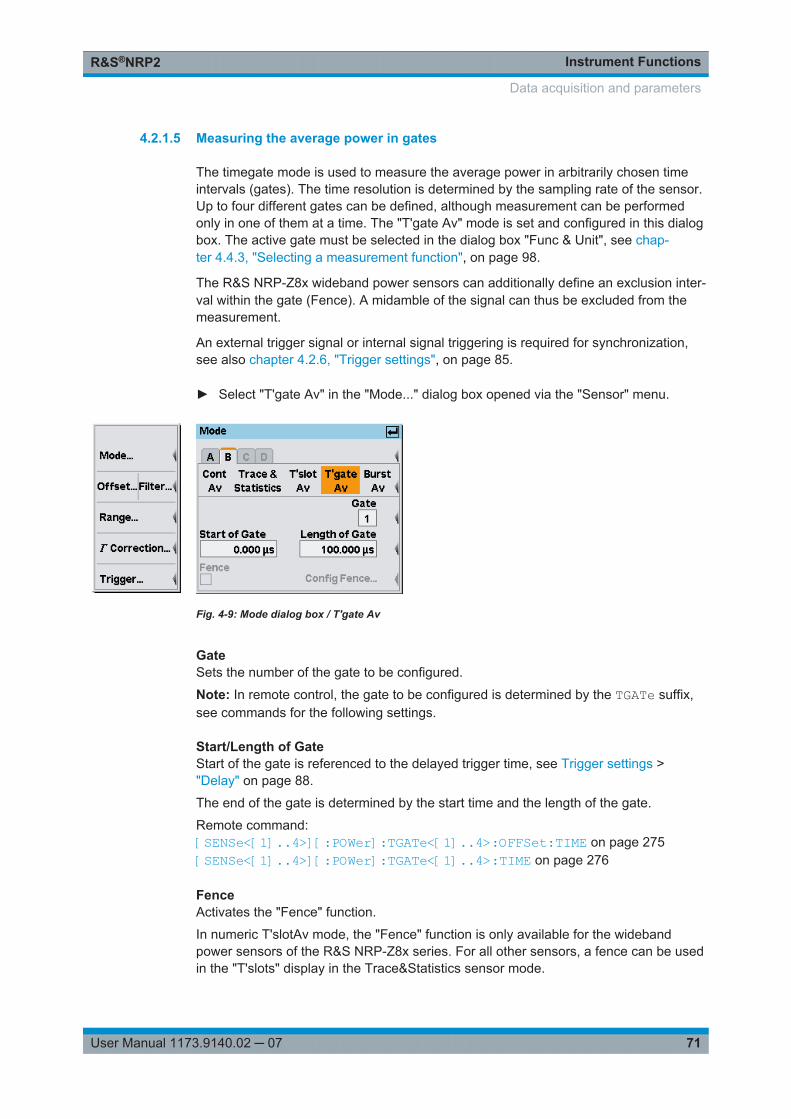
Instrument FunctionsR&S®NRP2
71User Manual 1173.9140.02 ─ 07
4.2.1.5 Measuring the average power in gates
The timegate mode is used to measure the average power in arbitrarily chosen timeintervals (gates). The time resolution is determined by the sampling rate of the sensor.Up to four different gates can be defined, although measurement can be performedonly in one of them at a time. The "T'gate Av" mode is set and configured in this dialogbox. The active gate must be selected in the dialog box "Func & Unit", see chap-ter 4.4.3, "Selecting a measurement function", on page 98.
The R&S NRP-Z8x wideband power sensors can additionally define an exclusion inter-val within the gate (Fence). A midamble of the signal can thus be excluded from themeasurement.
An external trigger signal or internal signal triggering is required for synchronization,see also chapter 4.2.6, "Trigger settings", on page 85.
► Select "T'gate Av" in the "Mode..." dialog box opened via the "Sensor" menu.
Fig. 4-9: Mode dialog box / T'gate Av
GateSets the number of the gate to be configured.
Note: In remote control, the gate to be configured is determined by the TGATe suffix,see commands for the following settings.
Start/Length of GateStart of the gate is referenced to the delayed trigger time, see Trigger settings >"Delay" on page 88.
The end of the gate is determined by the start time and the length of the gate.
Remote command: [SENSe<[1]..4>][:POWer]:TGATe<[1]..4>:OFFSet:TIME on page 275[SENSe<[1]..4>][:POWer]:TGATe<[1]..4>:TIME on page 276
FenceActivates the "Fence" function.
In numeric T'slotAv mode, the "Fence" function is only available for the widebandpower sensors of the R&S NRP-Z8x series. For all other sensors, a fence can be usedin the "T'slots" display in the Trace&Statistics sensor mode.
Data acquisition and parameters
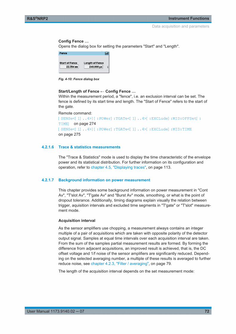
Instrument FunctionsR&S®NRP2
72User Manual 1173.9140.02 ─ 07
Config Fence …Opens the dialog box for setting the parameters "Start" and "Length".
Fig. 4-10: Fence dialog box
Start/Length of Fence ← Config Fence …Within the measurement period, a "fence", i.e. an exclusion interval can be set. Thefence is defined by its start time and length. The "Start of Fence" refers to the start ofthe gate.
Remote command: [SENSe<[1]..4>][:POWer]:TGATe<[1]..4>[:EXCLude]:MID:OFFSet[:TIME] on page 274[SENSe<[1]..4>][:POWer]:TGATe<[1]..4>[:EXCLude]:MID:TIMEon page 275
4.2.1.6 Trace & statistics measurements
The "Trace & Statistics" mode is used to display the time characteristic of the envelopepower and its statistical distribution. For further information on its configuration andoperation, refer to chapter 4.5, "Displaying traces", on page 113.
4.2.1.7 Background information on power measurement
This chapter provides some background information on power measurement in "ContAv", "T'slot Av", "T'gate Av" and "Burst Av" mode, smoothing, or what is the point ofdropout tolerance. Additionally, timing diagrams explain visually the relation betweentrigger, aquisition intervals and excluded time segments in "T'gate" or "T'slot" measure-ment mode.
Acquisition interval
As the sensor amplifiers use chopping, a measurement always contains an integermultiple of a pair of acquisitions which are taken with opposite polarity of the detectoroutput signal. Samples at equal time intervals over each acquisition interval are taken.From the sum of the samples partial measurement results are formed. By forming thedifference from adjacent acquisitions, an improved result is achieved, that is, the DCoffset voltage and 1/f noise of the sensor amplifiers are significantly reduced. Depend-ing on the selected averaging number, a multiple of these results is averaged to furtherreduce noise, see chapter 4.2.3, "Filter / averaging", on page 79.
The length of the acquisition interval depends on the set measurement mode:
Data acquisition and parameters
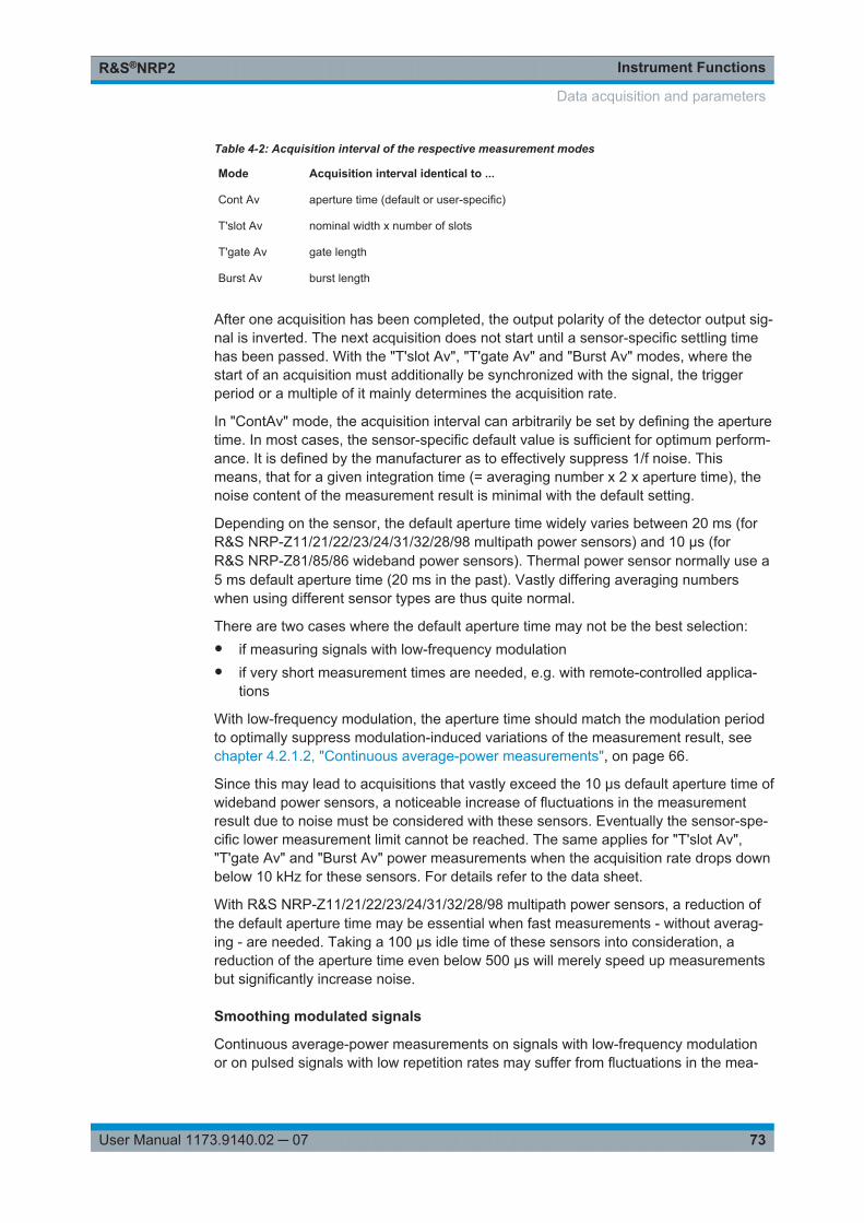
Instrument FunctionsR&S®NRP2
73User Manual 1173.9140.02 ─ 07
Table 4-2: Acquisition interval of the respective measurement modes
Mode Acquisition interval identical to ...
Cont Av aperture time (default or user-specific)
T'slot Av nominal width x number of slots
T'gate Av gate length
Burst Av burst length
After one acquisition has been completed, the output polarity of the detector output sig-nal is inverted. The next acquisition does not start until a sensor-specific settling timehas been passed. With the "T'slot Av", "T'gate Av" and "Burst Av" modes, where thestart of an acquisition must additionally be synchronized with the signal, the triggerperiod or a multiple of it mainly determines the acquisition rate.
In "ContAv" mode, the acquisition interval can arbitrarily be set by defining the aperturetime. In most cases, the sensor-specific default value is sufficient for optimum perform-ance. It is defined by the manufacturer as to effectively suppress 1/f noise. Thismeans, that for a given integration time (= averaging number x 2 x aperture time), thenoise content of the measurement result is minimal with the default setting.
Depending on the sensor, the default aperture time widely varies between 20 ms (forR&S NRP-Z11/21/22/23/24/31/32/28/98 multipath power sensors) and 10 µs (forR&S NRP-Z81/85/86 wideband power sensors). Thermal power sensor normally use a5 ms default aperture time (20 ms in the past). Vastly differing averaging numberswhen using different sensor types are thus quite normal.
There are two cases where the default aperture time may not be the best selection:● if measuring signals with low-frequency modulation● if very short measurement times are needed, e.g. with remote-controlled applica-
tions
With low-frequency modulation, the aperture time should match the modulation periodto optimally suppress modulation-induced variations of the measurement result, seechapter 4.2.1.2, "Continuous average-power measurements", on page 66.
Since this may lead to acquisitions that vastly exceed the 10 µs default aperture time ofwideband power sensors, a noticeable increase of fluctuations in the measurementresult due to noise must be considered with these sensors. Eventually the sensor-spe-cific lower measurement limit cannot be reached. The same applies for "T'slot Av","T'gate Av" and "Burst Av" power measurements when the acquisition rate drops downbelow 10 kHz for these sensors. For details refer to the data sheet.
With R&S NRP-Z11/21/22/23/24/31/32/28/98 multipath power sensors, a reduction ofthe default aperture time may be essential when fast measurements - without averag-ing - are needed. Taking a 100 µs idle time of these sensors into consideration, areduction of the aperture time even below 500 µs will merely speed up measurementsbut significantly increase noise.
Smoothing modulated signals
Continuous average-power measurements on signals with low-frequency modulationor on pulsed signals with low repetition rates may suffer from fluctuations in the mea-
Data acquisition and parameters
Instrument FunctionsR&S®NRP2
74User Manual 1173.9140.02 ─ 07
surement result, which are due to the acquisition time not being matched to the modu-lation (pulse) period. Although it is possible with R&S NRP-Zxx Power Sensors to setthe aperture time identical to a multiple integer of the period of the power envelope ofthe signal, this approach fails with a varying or unknown period.
In these cases it is recommended to activate smoothing. Instead of simply summing upthe samples within the acquisition interval, the samples are individually weighted priorto taking the mean. Samples at the beginning and at the end of the acquisition intervalare downscaled whereas the size of samples in the center of the acquisition interval isincreased (von Hann window). This way, fluctuations of the measurement result arereduced almost independently from the degree of the aperture time being matched tothe modulation period. The only aspect that must be considered is that the aperturetime has to be set to at least two or three modulation (pulse) periods in order to reachan efficient operation. Set aperture time accordingly, particularly if you are usingR&S NRP-Z81/85/86 wideband power sensors, which feature very low default aperturetimes.
The noise content of the measurement result is enlarged by approximately 30 % whensmoothing is activated. To compensate for this, the averaging number should be dou-bled compared to non-active smoothing. Therefore, smoothing may be not sufficientwhen measuring very low powers.
Dropout tolerance
The "Dropout" parameter facilitates the identification of the burst end of modulated sig-nals (e.g. NADC). Without this parameter, the end of the burst might erroneously bedetected within the burst owing to the considerable modulation-specific power drops ofsuch signals. "Dropout" is set at least for the duration of modulation-dependent powerdrops within the burst; thus, the end of the burst cannot be detected until the set timehas elapsed after the power has dropped below the trigger threshold. If the triggerthreshold is exceeded again during the dropout time, the process restarts from thebeginning.
Timing diagram of burst signals
The timing diagram below shows the relation between the following parameters:● Trigger threshold and trigger event● Trigger event, exclude intervals and measurement interval
Although the signal frequently falls below the trigger threshold during the burst, an endof the burst is not detected. The reason for this is that these drops are shorter than theset dropout time.
The last falling edge in the burst is detected as the end of the burst since the triggerthreshold is no longer exceeded during the dropout time indicated below
Data acquisition and parameters

Instrument FunctionsR&S®NRP2
75User Manual 1173.9140.02 ─ 07
Power
Time
Triggerthreshold
Dropout
Excluded from Start Excluded from End
Last falling edgein the burst
Trigger event
Measurementinterval
Fig. 4-11: Timing diagram of burst signals
Timing diagram of T'Slot Av signals
The timing diagrams that differ by externally and internally triggered events, show therelation between the listed parameters:● Trigger event, trigger delay and start of the first timeslot● Nominal width, exclude intervals and measurement interval of the timeslots
Time
Excluded from End
#1 #2 #3 #4
Width
Trigger event(external)
Measurementinterval #
Fig. 4-12: Measurement on timeslot signal with external triggering
Data acquisition and parameters
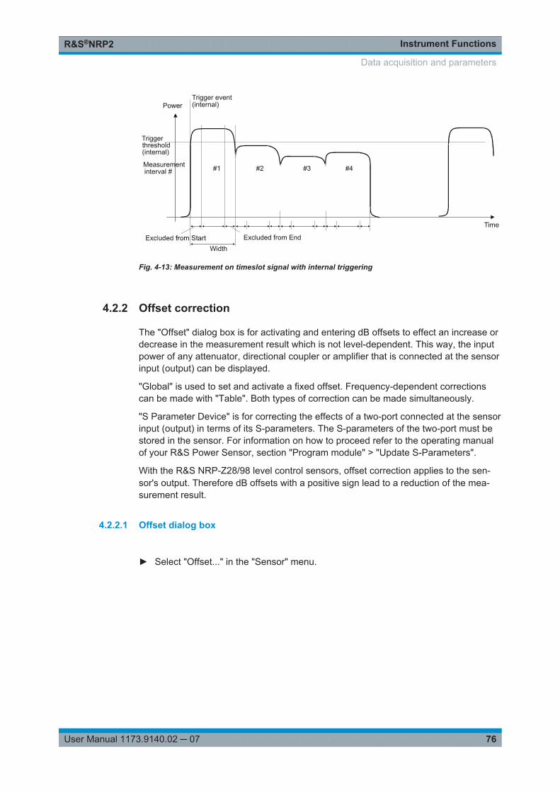
Instrument FunctionsR&S®NRP2
76User Manual 1173.9140.02 ─ 07
Time
Triggerthreshold(internal)
Excluded from End
#1 #2 #3 #4
Width
Trigger event(internal)
Measurementinterval #
Fig. 4-13: Measurement on timeslot signal with internal triggering
4.2.2 Offset correction
The "Offset" dialog box is for activating and entering dB offsets to effect an increase ordecrease in the measurement result which is not level-dependent. This way, the inputpower of any attenuator, directional coupler or amplifier that is connected at the sensorinput (output) can be displayed.
"Global" is used to set and activate a fixed offset. Frequency-dependent correctionscan be made with "Table". Both types of correction can be made simultaneously.
"S Parameter Device" is for correcting the effects of a two-port connected at the sensorinput (output) in terms of its S-parameters. The S-parameters of the two-port must bestored in the sensor. For information on how to proceed refer to the operating manualof your R&S Power Sensor, section "Program module" > "Update S-Parameters".
With the R&S NRP-Z28/98 level control sensors, offset correction applies to the sen-sor's output. Therefore dB offsets with a positive sign lead to a reduction of the mea-surement result.
4.2.2.1 Offset dialog box
► Select "Offset..." in the "Sensor" menu.
Data acquisition and parameters
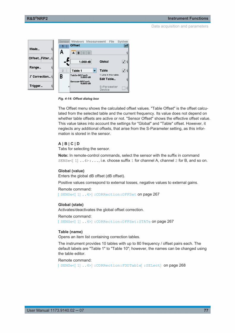
Instrument FunctionsR&S®NRP2
77User Manual 1173.9140.02 ─ 07
Fig. 4-14: Offset dialog box
The Offset menu shows the calculated offset values. "Table Offset" is the offset calcu-lated from the selected table and the current frequency. Its value does not depend onwhether table offsets are active or not. "Sensor Offset" shows the effective offset value.This value takes into account the settings for "Global" and "Table" offset. However, itneglects any additional offsets, that arise from the S-Parameter setting, as this infor-mation is stored in the sensor.
A | B | C | DTabs for selecting the sensor.
Note: In remote-control commands, select the sensor with the suffix in commandSENSe<[1]..4>:..., i.e. choose suffix 1 for channel A, channel 2 for B, and so on.
Global (value)Enters the global dB offset (dB offset).
Positive values correspond to external losses, negative values to external gains.
Remote command: [SENSe<[1]..4>]:CORRection:OFFSet on page 267
Global (state)Activates/deactivates the global offset correction.
Remote command: [SENSe<[1]..4>]:CORRection:OFFSet:STATe on page 267
Table (name)Opens an item list containing correction tables.
The instrument provides 10 tables with up to 80 frequency / offset pairs each. Thedefault labels are "Table 1" to "Table 10"; however, the names can be changed usingthe table editor.
Remote command: [SENSe<[1]..4>]:CORRection:FDOTable[:SELect] on page 268
Data acquisition and parameters
Instrument FunctionsR&S®NRP2
78User Manual 1173.9140.02 ─ 07
Table (state)Activates/deactivates the frequency-dependent offset correction specified in theselected table.
Remote command: [SENSe<[1]..4>]:CORRection:FDOTable:STATe on page 268
Edit Table ...Opens a dialog box for editing the selected offset correction table, see chapter 4.2.2.2,"Table editor for offset tables", on page 78.
Remote command: MEMory:TABLe:FREQuency on page 253MEMory:TABLe:GAIN[:MAGNitude] on page 253
S Parameter DeviceActivates the S-parameter data set stored in the sensor for a two-port that is connectedto the sensor input (output).
Remote command: [SENSe<[1]..4>]:CORRection:SPDevice:STATe on page 269
4.2.2.2 Table editor for offset tables
The R&S NRP2 provides a list editor for defining the frequency / offset value pairs.
Two table-editor modes are available:● Selection mode
In this mode, using the cursor keys ⇧ ⇩ ⇦ ⇨, you can select the number field youwant to "Edit", "Insert" or "Delete".Note: A long list can not be displayed in full length in the dialog box. The entriesare, therefore, viewed in a “window” which automatically scrolls up or down, if thecursor moves outside the visible section. The position of the currently active field isshown by the scroll bar.
● Edit modeWhen you press the "Edit" rocker switch the value in the selected field can be edi-ted. In this mode, the cursor keys cannot be used for selection, but can be used“normally” to edit values in the entry field.
► To open the table editor, select "Sensor" > "Mode" > "Offset", and then "EditTable..." in the "Offset" dialog box.
Data acquisition and parameters
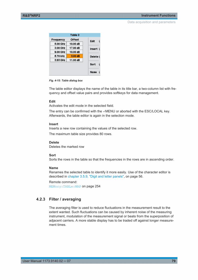
Instrument FunctionsR&S®NRP2
79User Manual 1173.9140.02 ─ 07
Fig. 4-15: Table dialog box
The table editor displays the name of the table in its title bar, a two-column list with fre-quency and offset value pairs and provides softkeys for data management.
EditActivates the edit mode in the selected field.
The entry can be confirmed with the ↵MENU or aborted with the ESC/LOCAL key.Afterwards, the table editor is again in the selection mode.
InsertInserts a new row containing the values of the selected row.
The maximum table size provides 80 rows.
DeleteDeletes the marked row
SortSorts the rows in the table so that the frequencies in the rows are in ascending order.
NameRenames the selected table to identify it more easily. Use of the character editor isdescribed in chapter 3.5.9, "Digit and letter panels", on page 56.
Remote command: MEMory:TABLe:MAP on page 254
4.2.3 Filter / averaging
The averaging filter is used to reduce fluctuations in the measurement result to theextent wanted. Such fluctuations can be caused by inherent noise of the measuringinstrument, modulation of the measurement signal or beats from the superposition ofadjacent carriers. A more stable display has to be traded off against longer measure-ment times.
Data acquisition and parameters
Instrument FunctionsR&S®NRP2
80User Manual 1173.9140.02 ─ 07
In manual mode, “longer measurement” does not mean that it takes longer to display anew result, but rather that it takes longer for the result to settle when the powerchanges.
The filter settings of the "Trace & Statistics" mode and the other modes, which exclu-sively provide average power values, differ significantly. The filter dialog box thus dis-plays different parameters depending on the selected display mode. Filtering in the"Trace & Statistics" mode is described in chapter 4.5.3.3, "Filtering settings",on page 118.
All average power values are obtained from a three-stage averaging process. First, amean value is formed for the acquisition interval given in table 4-2 - either by weightedor unweighted summation of samples.
A second measurement with reversed polarity of the detector output signal is then per-formed to suppress offset voltages and 1/f noise of the amplifier. A first result is formedby subtracting the second measured value from the first measured value. Thesequence of two consecutive measurements is repeated N times. The average value,which is obtained from the individual measurement results, is output. The number N isthe averaging number ("AvgNo"). To obtain a high output data rate, averaging in man-ual mode is performed continuously, i.e. a new result is fed into the averaging filterafter two acquisitions have been evaluated. The oldest result is taken out of the aver-aging filter and a new average value is calculated.
The averaging number can be selected automatically or it can be manually set to afixed value. As a starting point, automatic filtering should always be used. If the auto-matically selected filter setting proves to be not adequate, the averaging number canbe in(de)creased manually.
Two autofilter operating modes are provided:● "Normal"
The "Normal" mode finds a balance between measurement time and display noise.As an additional parameter, display resolution can be used to adjust the filter set-ting. With increasing resolution, i.e. an increasing number of digits in the measure-ment results, the averaging number also increases.
● "Fixed Noise"In the "Fixed Noise" mode, the averaging number is selected so that the sensorsintrinsic noise (2 standard deviations) does not exceed the specified "Noise Con-tent". To avoid very long settling times when the power is low, the averaging num-ber can be limited with the "Max Settling Time" parameter. If the display noise thenexceeds the set noise content, the symbol "S/N" is displayed.
Data acquisition and parameters
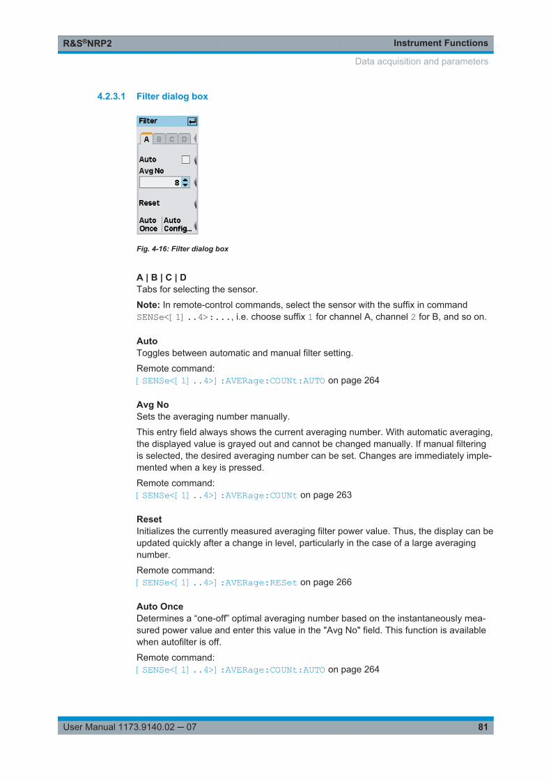
Instrument FunctionsR&S®NRP2
81User Manual 1173.9140.02 ─ 07
4.2.3.1 Filter dialog box
Fig. 4-16: Filter dialog box
A | B | C | DTabs for selecting the sensor.
Note: In remote-control commands, select the sensor with the suffix in commandSENSe<[1]..4>:..., i.e. choose suffix 1 for channel A, channel 2 for B, and so on.
AutoToggles between automatic and manual filter setting.
Remote command: [SENSe<[1]..4>]:AVERage:COUNt:AUTO on page 264
Avg NoSets the averaging number manually.
This entry field always shows the current averaging number. With automatic averaging,the displayed value is grayed out and cannot be changed manually. If manual filteringis selected, the desired averaging number can be set. Changes are immediately imple-mented when a key is pressed.
Remote command: [SENSe<[1]..4>]:AVERage:COUNt on page 263
ResetInitializes the currently measured averaging filter power value. Thus, the display can beupdated quickly after a change in level, particularly in the case of a large averagingnumber.
Remote command: [SENSe<[1]..4>]:AVERage:RESet on page 266
Auto OnceDetermines a “one-off” optimal averaging number based on the instantaneously mea-sured power value and enter this value in the "Avg No" field. This function is availablewhen autofilter is off.
Remote command: [SENSe<[1]..4>]:AVERage:COUNt:AUTO on page 264
Data acquisition and parameters
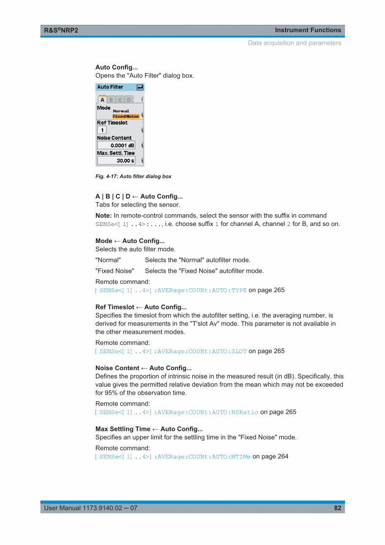
Instrument FunctionsR&S®NRP2
82User Manual 1173.9140.02 ─ 07
Auto Config...Opens the "Auto Filter" dialog box.
Fig. 4-17: Auto filter dialog box
A | B | C | D ← Auto Config...Tabs for selecting the sensor.
Note: In remote-control commands, select the sensor with the suffix in commandSENSe<[1]..4>:..., i.e. choose suffix 1 for channel A, channel 2 for B, and so on.
Mode ← Auto Config...Selects the auto filter mode.
"Normal" Selects the "Normal" autofilter mode.
"Fixed Noise" Selects the "Fixed Noise" autofilter mode.
Remote command: [SENSe<[1]..4>]:AVERage:COUNt:AUTO:TYPE on page 265
Ref Timeslot ← Auto Config...Specifies the timeslot from which the autofilter setting, i.e. the averaging number, isderived for measurements in the "T'slot Av" mode. This parameter is not available inthe other measurement modes.
Remote command: [SENSe<[1]..4>]:AVERage:COUNt:AUTO:SLOT on page 265
Noise Content ← Auto Config...Defines the proportion of intrinsic noise in the measured result (in dB). Specifically, thisvalue gives the permitted relative deviation from the mean which may not be exceededfor 95% of the observation time.
Remote command: [SENSe<[1]..4>]:AVERage:COUNt:AUTO:NSRatio on page 265
Max Settling Time ← Auto Config...Specifies an upper limit for the settling time in the "Fixed Noise" mode.
Remote command: [SENSe<[1]..4>]:AVERage:COUNt:AUTO:MTIMe on page 264
Data acquisition and parameters

Instrument FunctionsR&S®NRP2
83User Manual 1173.9140.02 ─ 07
4.2.4 Measurement ranges
The power sensors of the R&S NRP series avoid range switching. Some of them, likethe thermal ones of the R&S NRP-Z5x series and the wideband power sensors of theR&S NRP-Z8x series, have only one measurement range. All other sensors featuretwo or three measurement ranges. These ranges are called measurement pathsbecause they are operated in parallel (simultaneously). With automatic range selection,measurement paths which are neither overdriven nor underdriven are selected forevaluation. No range switching occurs at all. Adjacent paths overlap by about 6 dB, theso-called transition region. Therefore, the final result may be composed by the mea-surement results of two paths within certain power ranges. Transition regions can beoffset from the default settings to meet the demands of signals with high peak-to-aver-age ratio.
4.2.4.1 Sensor range dialog box
Automatic or manual path selection can be chosen in the "Range" dialog box,accessed via the "Sensor" menu. No function is available for power sensors that useonly one measurement range.
The "Auto" range function always selects the most suitable paths. With "User def'dtransition" deactivated, the default overlap regions between adjacent paths are consid-ered. The offset value can be modified at any time during "Auto" range operation, but itis only considered with an activated "User def'd transition" checkbox.
Only offsets with a negative sign are allowed. This means that transition regions canonly be shifted to lower power levels. Thus, paths can be excluded from evaluation wellbefore they exhibit noticeable linearity errors with critical signals. Only the most insen-sitive path cannot be protected by this measure.
The performance of the sensors can effectively be improved by this measure withrespect to linearity errors when applying signals with high peak-to-average ratios. How-ever, there is a certain downside regarding speed and noise. If an offset value of e.g.-10 dB is entered, this means that paths can be underdriven by an amount of 10 dBwith respect to the default setting. This way, the amount of inherent sensor noise willbecome more evident or the settling time will increase if one counteracts with a higheraveraging number. That is why there is little point in entering offsets less than -10 dB.As a rule of thumb, linearity errors introduced by signals with high peak-to-averageratios, are reduced according to the offset value, e.g. by a factor of four when entering-6 dB.
Manual path selection can be chosen by deactivating the "Auto" checkbox and select-ing the preferred path in the "Path" selection box. Testing the drive range of an individ-ual path or avoiding the noise contribution of the adjacent path may be a good reasonfor selecting manual operation.
Data acquisition and parameters
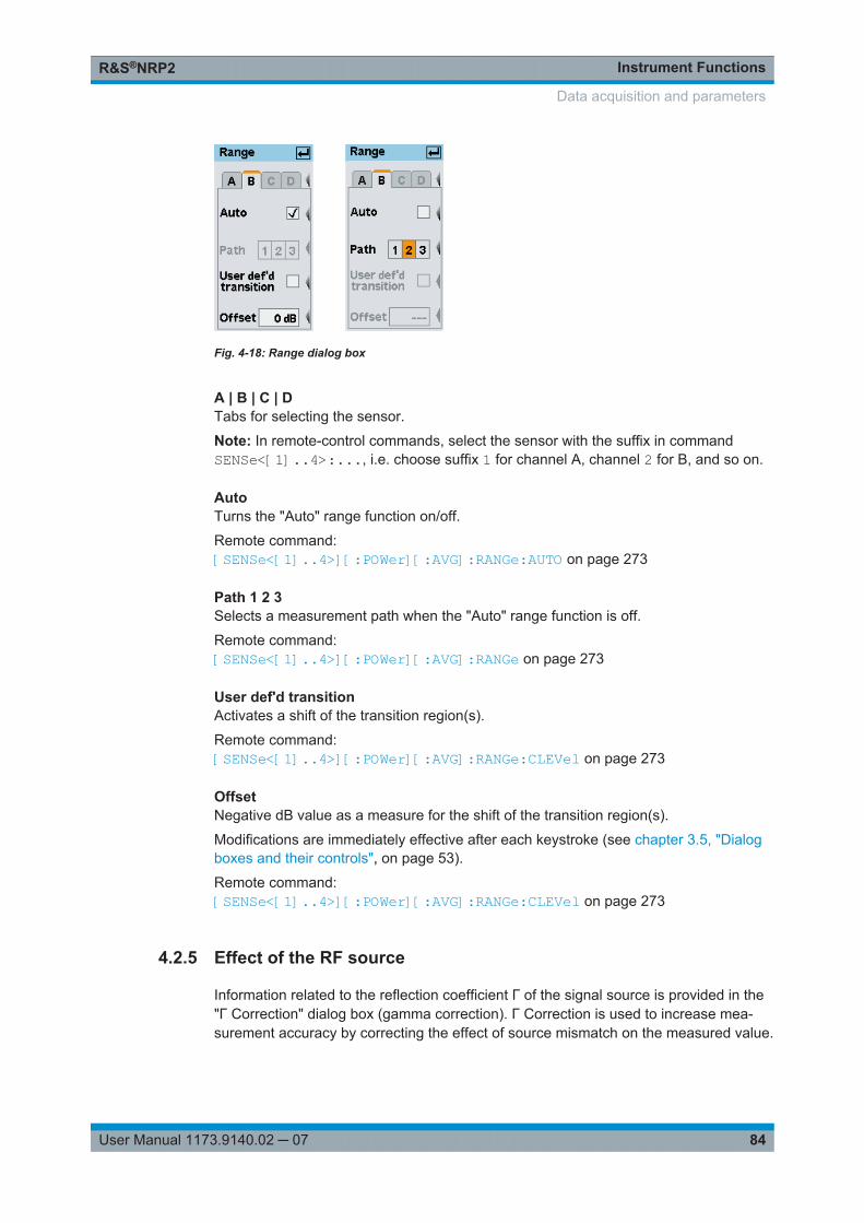
Instrument FunctionsR&S®NRP2
84User Manual 1173.9140.02 ─ 07
Fig. 4-18: Range dialog box
A | B | C | DTabs for selecting the sensor.
Note: In remote-control commands, select the sensor with the suffix in commandSENSe<[1]..4>:..., i.e. choose suffix 1 for channel A, channel 2 for B, and so on.
AutoTurns the "Auto" range function on/off.
Remote command: [SENSe<[1]..4>][:POWer][:AVG]:RANGe:AUTO on page 273
Path 1 2 3Selects a measurement path when the "Auto" range function is off.
Remote command: [SENSe<[1]..4>][:POWer][:AVG]:RANGe on page 273
User def'd transitionActivates a shift of the transition region(s).
Remote command: [SENSe<[1]..4>][:POWer][:AVG]:RANGe:CLEVel on page 273
OffsetNegative dB value as a measure for the shift of the transition region(s).
Modifications are immediately effective after each keystroke (see chapter 3.5, "Dialogboxes and their controls", on page 53).
Remote command: [SENSe<[1]..4>][:POWer][:AVG]:RANGe:CLEVel on page 273
4.2.5 Effect of the RF source
Information related to the reflection coefficient Γ of the signal source is provided in the"Γ Correction" dialog box (gamma correction). Γ Correction is used to increase mea-surement accuracy by correcting the effect of source mismatch on the measured value.
Data acquisition and parameters
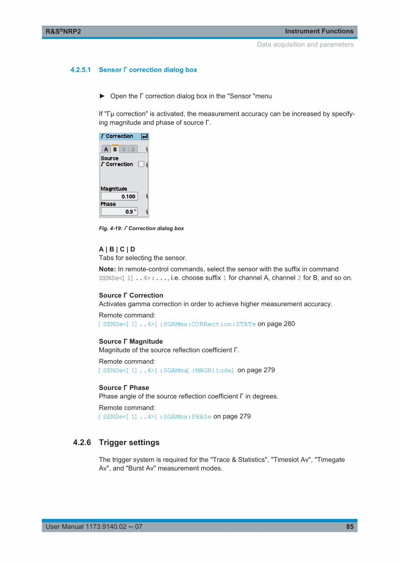
Instrument FunctionsR&S®NRP2
85User Manual 1173.9140.02 ─ 07
4.2.5.1 Sensor Γ correction dialog box
► Open the Γ correction dialog box in the "Sensor "menu
If "Γµ correction" is activated, the measurement accuracy can be increased by specify-ing magnitude and phase of source Γ.
Fig. 4-19: Γ Correction dialog box
A | B | C | DTabs for selecting the sensor.
Note: In remote-control commands, select the sensor with the suffix in commandSENSe<[1]..4>:..., i.e. choose suffix 1 for channel A, channel 2 for B, and so on.
Source Γ CorrectionActivates gamma correction in order to achieve higher measurement accuracy.
Remote command: [SENSe<[1]..4>]:SGAMma:CORRection:STATe on page 280
Source Γ MagnitudeMagnitude of the source reflection coefficient Γ.
Remote command: [SENSe<[1]..4>]:SGAMma[:MAGNitude] on page 279
Source Γ PhasePhase angle of the source reflection coefficient Γ in degrees.
Remote command: [SENSe<[1]..4>]:SGAMma:PHASe on page 279
4.2.6 Trigger settings
The trigger system is required for the "Trace & Statistics", "Timeslot Av", "TimegateAv", and "Burst Av" measurement modes.
Data acquisition and parameters
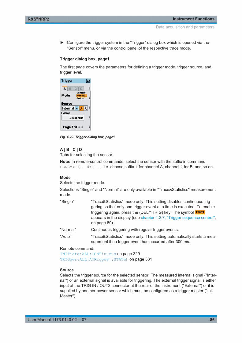
Instrument FunctionsR&S®NRP2
86User Manual 1173.9140.02 ─ 07
► Configure the trigger system in the "Trigger" dialog box which is opened via the"Sensor" menu, or via the control panel of the respective trace mode.
Trigger dialog box, page1
The first page covers the parameters for defining a trigger mode, trigger source, andtrigger level.
Fig. 4-20: Trigger dialog box, page1
A | B | C | DTabs for selecting the sensor.
Note: In remote-control commands, select the sensor with the suffix in commandSENSe<[1]..4>:..., i.e. choose suffix 1 for channel A, channel 2 for B, and so on.
ModeSelects the trigger mode.
Selections "Single" and "Normal" are only available in "Trace&Statistics" measurementmode.
"Single" "Trace&Statistics" mode only. This setting disables continuous trig-gering so that only one trigger event at a time is executed. To enabletriggering again, press the (DEL/1TRIG) key. The symbol appears in the display (see chapter 4.2.7, "Trigger sequence control",on page 89).
"Normal" Continuous triggering with regular trigger events.
"Auto" "Trace&Statistics" mode only. This setting automatically starts a mea-surement if no trigger event has occurred after 300 ms.
Remote command: INITiate:ALL:CONTinuous on page 329TRIGger:ALL:ATRigger[:STATe] on page 331
SourceSelects the trigger source for the selected sensor. The measured internal signal ("Inter-nal") or an external signal is available for triggering. The external trigger signal is eitherinput at the TRIG IN / OUT2 connector at the rear of the instrument ("External") or it issupplied by another power sensor which must be configured as a trigger master ("Int.Master").
Data acquisition and parameters

Instrument FunctionsR&S®NRP2
87User Manual 1173.9140.02 ─ 07
Note: In addition to using an internal or external trigger source, a trigger event can beforced using the DEL/1TRIG hardkey, see chapter 4.2.7, "Trigger sequence control",on page 89.
"Internal" The trigger event for the selected sensor is derived from the mea-sured signal.
"External" The trigger event for the selected sensor is derived from the triggerbus. The trigger signal on the trigger bus is either input at the TRIGIN / OUT2 connector at the rear of the instrument or it is provided byanother sensor.If the trigger signal is input at the TRIG IN / OUT2 connector, the con-nector must be configured for "Trigger In" in the "System" menu, seechapter 4.7.2.2, "I/O 2 interface", on page 155.If the trigger signal is provided by another sensor, this sensor must beconfigured as trigger master, see below, "Int. Master".
"Int. Master" The selected power sensor is automatically configured as triggermaster and set to internal triggering. Any previously defined triggermaster is disabled and an external trigger signal at the TRIG IN /OUT2 connector is ignored.The trigger master is used as the external trigger source for all othersensors.
Remote command: TRIGger:ALL:SOURce on page 334
SlopeSets the polarity of the active slope of the externally or internally applied trigger signal,see Source.
" Positive" The rising edge of the trigger signal is active.
"Negative" The falling edge of the trigger signal is active.
Remote command: TRIGger<[1]..4>:SLOPe on page 334
LevelSets the trigger threshold for internal triggering. Depending on the slope polarity, a ris-ing or a falling edge will execute a trigger event when crossing the threshold. Modifica-tions of the level are immediately effective (see chapter 3.5, "Dialog boxes and theircontrols", on page 53).
Remote command: TRIGger:ALL:LEVel on page 333
PageSwitches to the next page of the dialog box.
Trigger dialog box (2)The second page covers the parameters for defining a trigger delay and a dropout timeto prevent accidental triggering.
Data acquisition and parameters
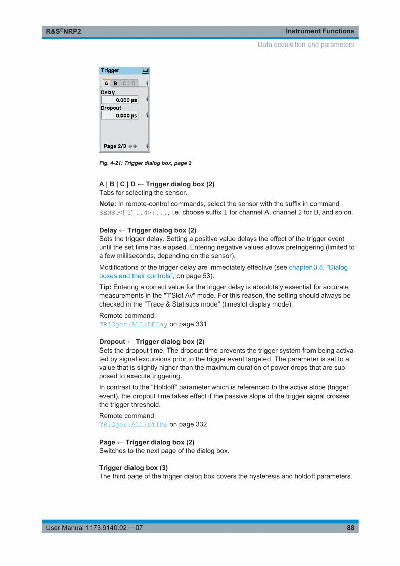
Instrument FunctionsR&S®NRP2
88User Manual 1173.9140.02 ─ 07
Fig. 4-21: Trigger dialog box, page 2
A | B | C | D ← Trigger dialog box (2)Tabs for selecting the sensor.
Note: In remote-control commands, select the sensor with the suffix in commandSENSe<[1]..4>:..., i.e. choose suffix 1 for channel A, channel 2 for B, and so on.
Delay ← Trigger dialog box (2)Sets the trigger delay. Setting a positive value delays the effect of the trigger eventuntil the set time has elapsed. Entering negative values allows pretriggering (limited toa few milliseconds, depending on the sensor).
Modifications of the trigger delay are immediately effective (see chapter 3.5, "Dialogboxes and their controls", on page 53).
Tip: Entering a correct value for the trigger delay is absolutely essential for accuratemeasurements in the "T'Slot Av" mode. For this reason, the setting should always bechecked in the "Trace & Statistics mode" (timeslot display mode).
Remote command: TRIGger:ALL:DELay on page 331
Dropout ← Trigger dialog box (2)Sets the dropout time. The dropout time prevents the trigger system from being activa-ted by signal excursions prior to the trigger event targeted. The parameter is set to avalue that is slightly higher than the maximum duration of power drops that are sup-posed to execute triggering.
In contrast to the "Holdoff" parameter which is referenced to the active slope (triggerevent), the dropout time takes effect if the passive slope of the trigger signal crossesthe trigger threshold.
Remote command: TRIGger:ALL:DTIMe on page 332
Page ← Trigger dialog box (2)Switches to the next page of the dialog box.
Trigger dialog box (3)The third page of the trigger dialog box covers the hysteresis and holdoff parameters.
Data acquisition and parameters
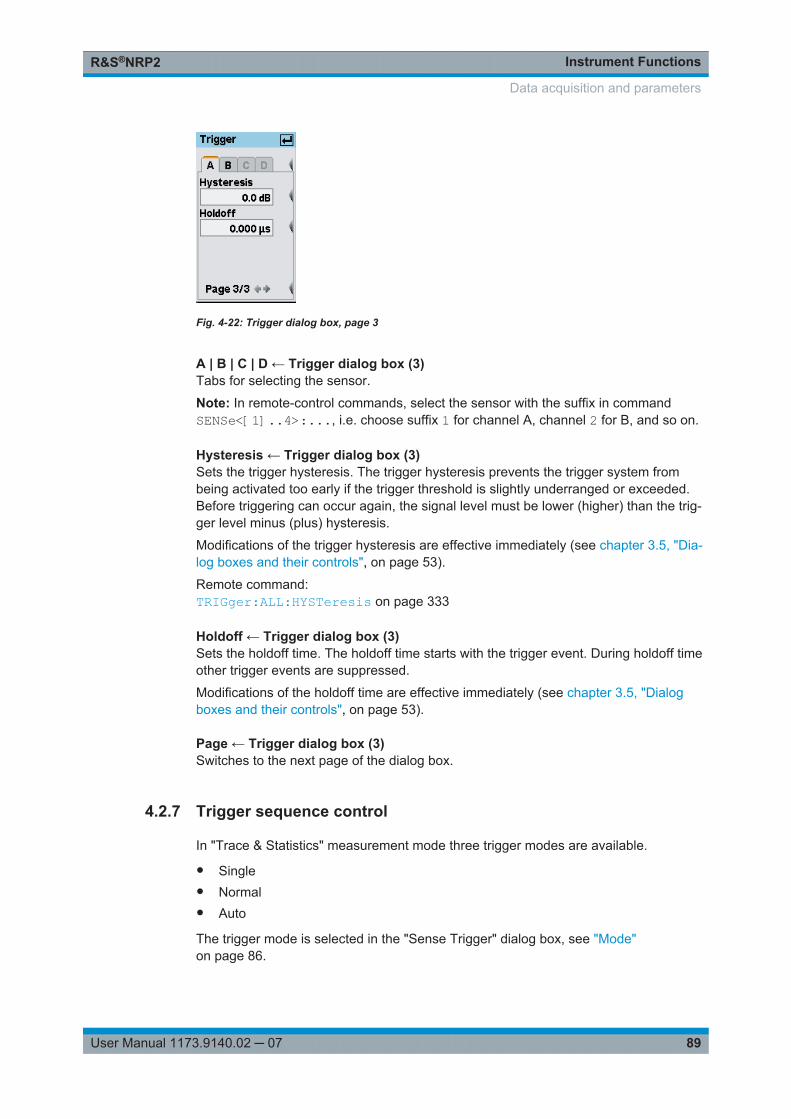
Instrument FunctionsR&S®NRP2
89User Manual 1173.9140.02 ─ 07
Fig. 4-22: Trigger dialog box, page 3
A | B | C | D ← Trigger dialog box (3)Tabs for selecting the sensor.
Note: In remote-control commands, select the sensor with the suffix in commandSENSe<[1]..4>:..., i.e. choose suffix 1 for channel A, channel 2 for B, and so on.
Hysteresis ← Trigger dialog box (3)Sets the trigger hysteresis. The trigger hysteresis prevents the trigger system frombeing activated too early if the trigger threshold is slightly underranged or exceeded.Before triggering can occur again, the signal level must be lower (higher) than the trig-ger level minus (plus) hysteresis.
Modifications of the trigger hysteresis are effective immediately (see chapter 3.5, "Dia-log boxes and their controls", on page 53).
Remote command: TRIGger:ALL:HYSTeresis on page 333
Holdoff ← Trigger dialog box (3)Sets the holdoff time. The holdoff time starts with the trigger event. During holdoff timeother trigger events are suppressed.
Modifications of the holdoff time are effective immediately (see chapter 3.5, "Dialogboxes and their controls", on page 53).
Page ← Trigger dialog box (3)Switches to the next page of the dialog box.
4.2.7 Trigger sequence control
In "Trace & Statistics" measurement mode three trigger modes are available.
● Single● Normal● Auto
The trigger mode is selected in the "Sense Trigger" dialog box, see "Mode"on page 86.
Data acquisition and parameters
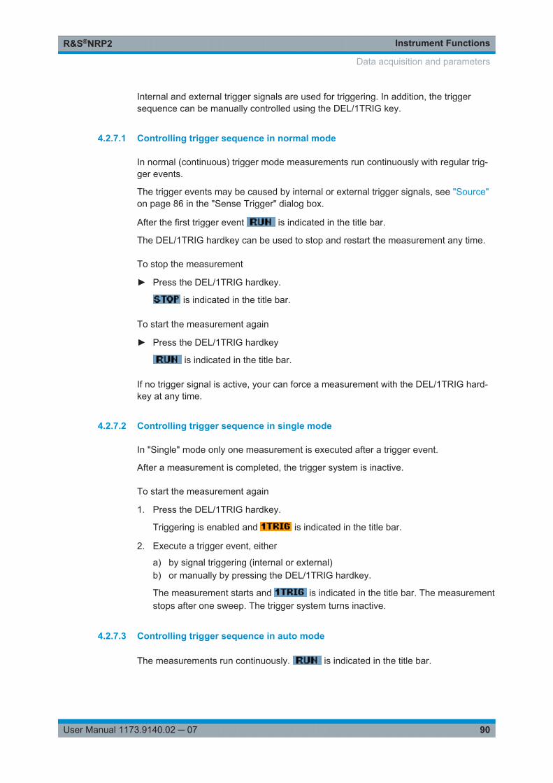
Instrument FunctionsR&S®NRP2
90User Manual 1173.9140.02 ─ 07
Internal and external trigger signals are used for triggering. In addition, the triggersequence can be manually controlled using the DEL/1TRIG key.
4.2.7.1 Controlling trigger sequence in normal mode
In normal (continuous) trigger mode measurements run continuously with regular trig-ger events.
The trigger events may be caused by internal or external trigger signals, see "Source"on page 86 in the "Sense Trigger" dialog box.
After the first trigger event is indicated in the title bar.
The DEL/1TRIG hardkey can be used to stop and restart the measurement any time.
To stop the measurement
► Press the DEL/1TRIG hardkey.
is indicated in the title bar.
To start the measurement again
► Press the DEL/1TRIG hardkey
is indicated in the title bar.
If no trigger signal is active, your can force a measurement with the DEL/1TRIG hard-key at any time.
4.2.7.2 Controlling trigger sequence in single mode
In "Single" mode only one measurement is executed after a trigger event.
After a measurement is completed, the trigger system is inactive.
To start the measurement again
1. Press the DEL/1TRIG hardkey.
Triggering is enabled and is indicated in the title bar.
2. Execute a trigger event, either
a) by signal triggering (internal or external)b) or manually by pressing the DEL/1TRIG hardkey.
The measurement starts and is indicated in the title bar. The measurementstops after one sweep. The trigger system turns inactive.
4.2.7.3 Controlling trigger sequence in auto mode
The measurements run continuously. is indicated in the title bar.
Data acquisition and parameters

Instrument FunctionsR&S®NRP2
91User Manual 1173.9140.02 ─ 07
To stop the measurement
► Press the DEL/1TRIG hardkey.
is indicated in the title bar.
To start the measurement again
► Press the DEL/1TRIG hardkey.
is indicated in the title bar.
4.3 Displaying measurement results
The R&S NRP2 provides a total of four windows for displaying results.
4.3.1 Arranging windows
Windows are displayed in numerical order from the top to the bottom of the screen.The R&S NRP2 automatically selects the window size according to the number of dis-played windows.
Fig. 4-23: Arranging windows
4.3.2 Labeling windows
The windows are numbered from 1 to 4 and are therefore clearly identifiable. Bydefault, they are labeled by the window’s number (1 to 4). The label is displayed in thetop left of the title bar.
Windows can also be assigned a name, see "Window Name" in the "File" menu. Thename is displayed in the window’s title bar . Assigning meaningful names to the win-dows makes it much easier to recognize the associated measurement.. A name like"Amplifier output" is more informative than "Channel A" or "Window 2".
The names of the windows are also stored in the setups.
Displaying measurement results
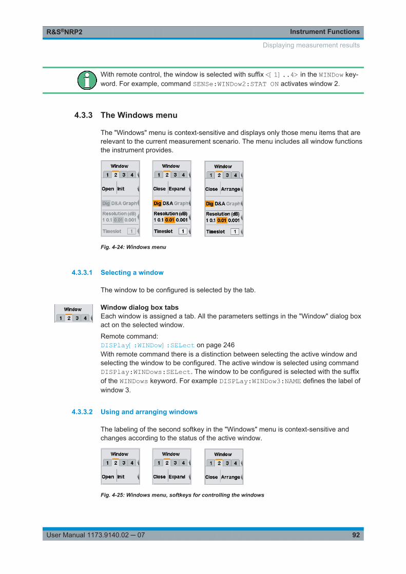
Instrument FunctionsR&S®NRP2
92User Manual 1173.9140.02 ─ 07
With remote control, the window is selected with suffix <[1]..4> in the WINDow key-word. For example, command SENSe:WINDow2:STAT ON activates window 2.
4.3.3 The Windows menu
The "Windows" menu is context-sensitive and displays only those menu items that arerelevant to the current measurement scenario. The menu includes all window functionsthe instrument provides.
Fig. 4-24: Windows menu
4.3.3.1 Selecting a window
The window to be configured is selected by the tab.
Window dialog box tabsEach window is assigned a tab. All the parameters settings in the "Window" dialog boxact on the selected window.
Remote command: DISPlay[:WINDow]:SELect on page 246With remote command there is a distinction between selecting the active window andselecting the window to be configured. The active window is selected using commandDISPlay:WINDows:SELect. The window to be configured is selected with the suffixof the WINDows keyword. For example DISPLay:WINDow3:NAME defines the label ofwindow 3.
4.3.3.2 Using and arranging windows
The labeling of the second softkey in the "Windows" menu is context-sensitive andchanges according to the status of the active window.
Fig. 4-25: Windows menu, softkeys for controlling the windows
Displaying measurement results
Instrument FunctionsR&S®NRP2
93User Manual 1173.9140.02 ─ 07
OpenOpens the selected window with its previous settings, i.e. "Open" restores a measure-ment that has been removed from the display.
Remote command: DISPlay[:WINDow]<[1]..4>[:STATe] on page 247
InitInitializes the selected window, i.e. "Init" configures a completely new measurementwith preset values.
CloseCloses the selected window. The sizes of the remaining windows are adjusted accord-ingly.
Remote command: DISPlay[:WINDow]<[1]..4>[:STATe] on page 247
ExpandExpands all open windows to the full display height. Only the selected window is dis-played while the other windows are masked by the selected window. However, themasked windows are still open and can be selected in the sequence "1 2 3 4" in thewindows menu or by means of the up/down cursor keys.
Full height windows display all relevant parameters. The enhanced control functionsoffered by the "Trace & Statistics" mode are available only if the windows are fullheight. For a graphical representation of the various window types and a description ofsymbols see chapter 3.6.1, "Window sizes and types", on page 57 and chapter 3.6.2,"Special symbols", on page 58.
Remote command: DISPlay[:WINDow]:SIZE on page 246
ArrangeReduces the full height windows to their normal size. The windows are displayedsimultanously again.
Remote command: DISPlay[:WINDow]:SIZE on page 246
4.3.3.3 Selecting the result display mode
Three result display modes are available in the windows menu. The result displaymode determines how the measured values are presented.
Dig D&A GraphSelects the display mode.
The parameter settings below the display mode change according to the selectedmode, see chapter 4.3.3.4, "Configuring the result display", on page 95.
Displaying measurement results
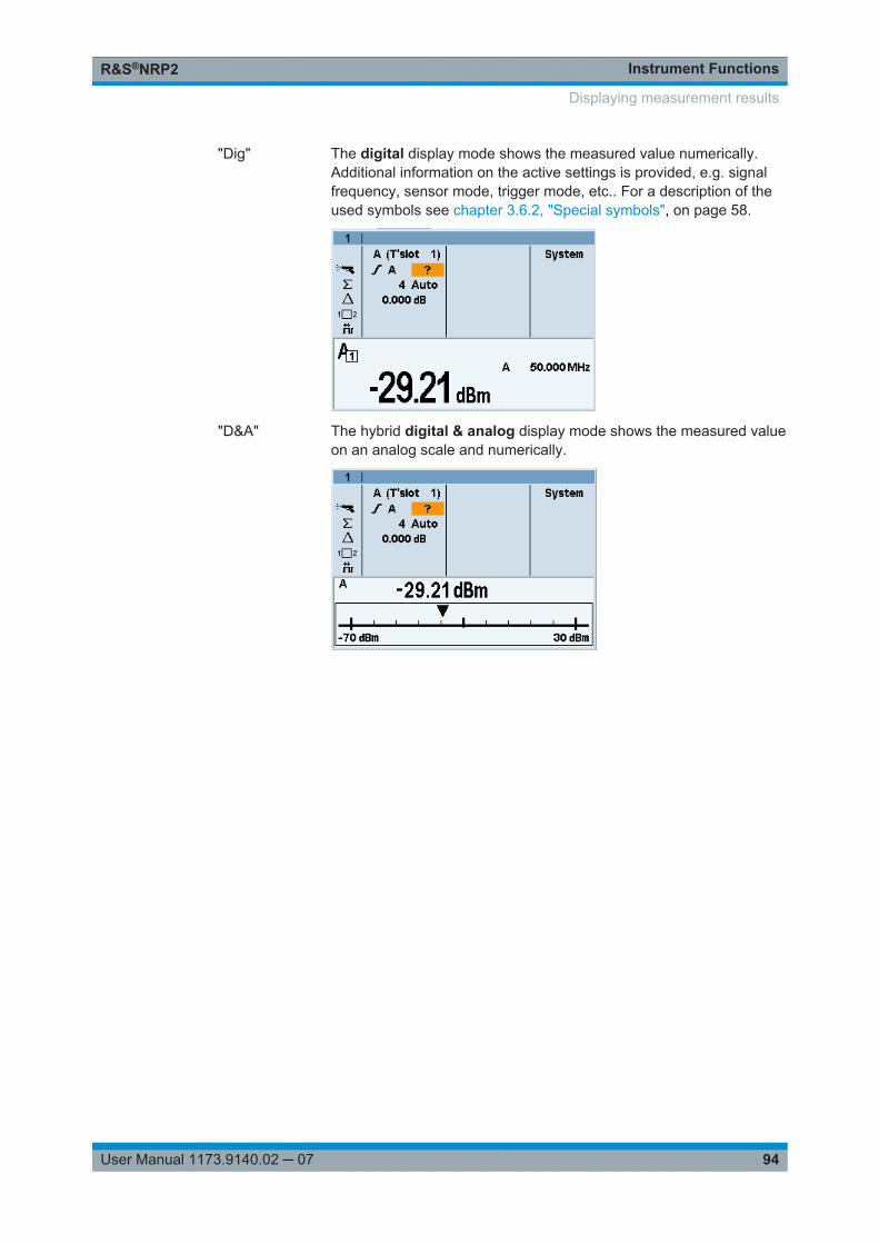
Instrument FunctionsR&S®NRP2
94User Manual 1173.9140.02 ─ 07
"Dig" The digital display mode shows the measured value numerically.Additional information on the active settings is provided, e.g. signalfrequency, sensor mode, trigger mode, etc.. For a description of theused symbols see chapter 3.6.2, "Special symbols", on page 58.
"D&A" The hybrid digital & analog display mode shows the measured valueon an analog scale and numerically.
Displaying measurement results
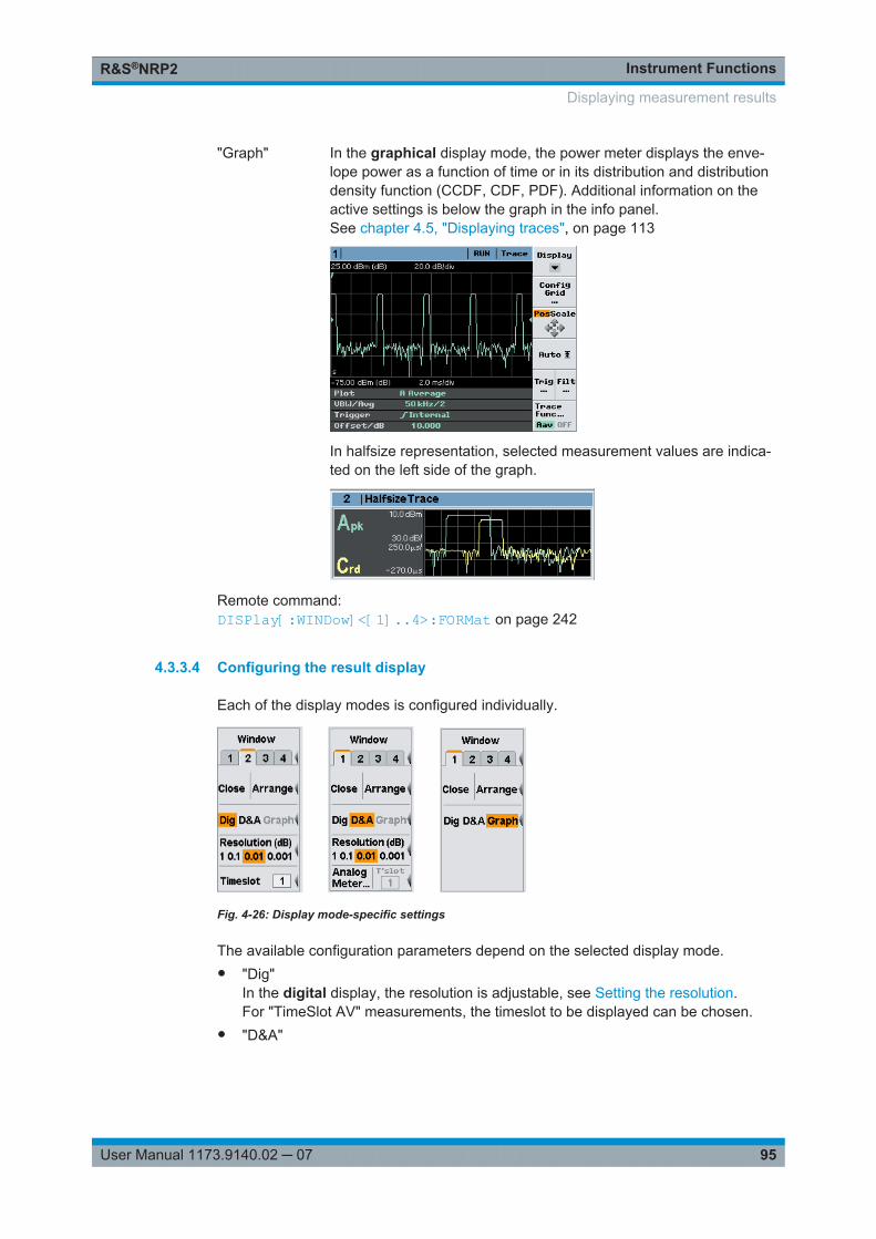
Instrument FunctionsR&S®NRP2
95User Manual 1173.9140.02 ─ 07
"Graph" In the graphical display mode, the power meter displays the enve-lope power as a function of time or in its distribution and distributiondensity function (CCDF, CDF, PDF). Additional information on theactive settings is below the graph in the info panel.See chapter 4.5, "Displaying traces", on page 113
In halfsize representation, selected measurement values are indica-ted on the left side of the graph.
Remote command: DISPlay[:WINDow]<[1]..4>:FORMat on page 242
4.3.3.4 Configuring the result display
Each of the display modes is configured individually.
Fig. 4-26: Display mode-specific settings
The available configuration parameters depend on the selected display mode.● "Dig"
In the digital display, the resolution is adjustable, see Setting the resolution.For "TimeSlot AV" measurements, the timeslot to be displayed can be chosen.
● "D&A"
Displaying measurement results
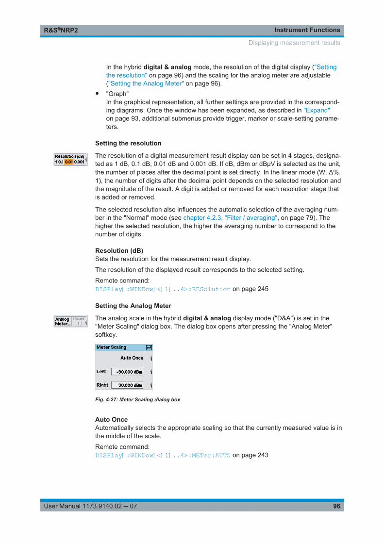
Instrument FunctionsR&S®NRP2
96User Manual 1173.9140.02 ─ 07
In the hybrid digital & analog mode, the resolution of the digital display ("Settingthe resolution" on page 96) and the scaling for the analog meter are adjustable("Setting the Analog Meter" on page 96).
● "Graph"In the graphical representation, all further settings are provided in the correspond-ing diagrams. Once the window has been expanded, as described in "Expand"on page 93, additional submenus provide trigger, marker or scale-setting parame-ters.
Setting the resolution
The resolution of a digital measurement result display can be set in 4 stages, designa-ted as 1 dB, 0.1 dB, 0.01 dB and 0.001 dB. If dB, dBm or dBμV is selected as the unit,the number of places after the decimal point is set directly. In the linear mode (W, Δ%,1), the number of digits after the decimal point depends on the selected resolution andthe magnitude of the result. A digit is added or removed for each resolution stage thatis added or removed.
The selected resolution also influences the automatic selection of the averaging num-ber in the "Normal" mode (see chapter 4.2.3, "Filter / averaging", on page 79). Thehigher the selected resolution, the higher the averaging number to correspond to thenumber of digits.
Resolution (dB)Sets the resolution for the measurement result display.
The resolution of the displayed result corresponds to the selected setting.
Remote command: DISPlay[:WINDow]<[1]..4>:RESolution on page 245
Setting the Analog Meter
The analog scale in the hybrid digital & analog display mode ("D&A") is set in the"Meter Scaling" dialog box. The dialog box opens after pressing the "Analog Meter"softkey.
Fig. 4-27: Meter Scaling dialog box
Auto OnceAutomatically selects the appropriate scaling so that the currently measured value is inthe middle of the scale.
Remote command: DISPlay[:WINDow]<[1]..4>:METer:AUTO on page 243
Displaying measurement results
Instrument FunctionsR&S®NRP2
97User Manual 1173.9140.02 ─ 07
LeftEnter the left end-of-scale value.
Remote command: DISPlay[:WINDow]<[1]..4>:METer:LOWer on page 243
RightEnter the right end-of-scale value.
Remote command: DISPlay[:WINDow]<[1]..4>:METer:UPPer on page 244
Scrolling between timeslots
In the "Timeslot Av" mode, the timeslot to be displayed can be chosen.
TimeslotSelects one timeslot out of a complete structure to show its mean power in the activewindow.
If you want to display further timeslots simultaneously, a separate window must beopened and configured for each additional timeslot.
Remote command: DISPlay[:WINDow]<[1]..4>:TSLot on page 248
4.4 Configuring measurements
The R&S NRP2 can perform up to four measurements simultaneously. Each measure-ment is configured separately in a window. Measurement parameters are set in the"Measurement" menu.
For every window opened via the "Windows" menu, a measurement in the "Measure-ment" menu can be configured. The measurement channels (A, B, C and D), the pro-cessing of the measured values (ratio, difference), the result unit and additional infor-mation (measurement uncertainty, max, min) are defined.
Configuring a measurement does not change the sensor operating modes that havebeen set in the "Mode" menu.
In remote control mode, the instrument allows the configuration of a total of 8 measure-ments. However, only measurement 1 to 4 can be assigned a result window. Measure-ments number 5 to 8 can only be evaluated via remote control.
4.4.1 The Measurement menu
The "Measurement" menu contains the functions required to configure measurements.
Configuring measurements
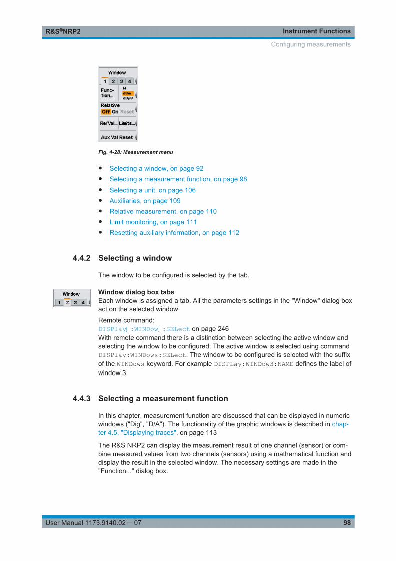
Instrument FunctionsR&S®NRP2
98User Manual 1173.9140.02 ─ 07
Fig. 4-28: Measurement menu
● Selecting a window, on page 92● Selecting a measurement function, on page 98● Selecting a unit, on page 106● Auxiliaries, on page 109● Relative measurement, on page 110● Limit monitoring, on page 111● Resetting auxiliary information, on page 112
4.4.2 Selecting a window
The window to be configured is selected by the tab.
Window dialog box tabsEach window is assigned a tab. All the parameters settings in the "Window" dialog boxact on the selected window.
Remote command: DISPlay[:WINDow]:SELect on page 246With remote command there is a distinction between selecting the active window andselecting the window to be configured. The active window is selected using commandDISPlay:WINDows:SELect. The window to be configured is selected with the suffixof the WINDows keyword. For example DISPLay:WINDow3:NAME defines the label ofwindow 3.
4.4.3 Selecting a measurement function
In this chapter, measurement function are discussed that can be displayed in numericwindows ("Dig", "D/A"). The functionality of the graphic windows is described in chap-ter 4.5, "Displaying traces", on page 113
The R&S NRP2 can display the measurement result of one channel (sensor) or com-bine measured values from two channels (sensors) using a mathematical function anddisplay the result in the selected window. The necessary settings are made in the"Function..." dialog box.
Configuring measurements
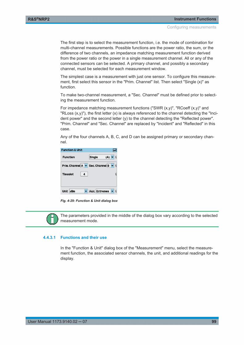
Instrument FunctionsR&S®NRP2
99User Manual 1173.9140.02 ─ 07
The first step is to select the measurement function, i.e. the mode of combination formulti-channel measurements. Possible functions are the power ratio, the sum, or thedifference of two channels, an impedance matching measurement function derivedfrom the power ratio or the power in a single measurement channel. All or any of theconnected sensors can be selected. A primary channel, and possibly a secondarychannel, must be selected for each measurement window.
The simplest case is a measurement with just one sensor. To configure this measure-ment, first select this sensor in the "Prim. Channel" list. Then select "Single (x)" asfunction.
To make two-channel measurement, a "Sec. Channel" must be defined prior to select-ing the measurement function.
For impedance matching measurement functions ("SWR (x,y)", "RCoeff (x,y)" and"RLoss (x,y)"), the first letter (x) is always referenced to the channel detecting the "Inci-dent power" and the second letter (y) to the channel detecting the "Reflected power"."Prim. Channel" and "Sec. Channel" are replaced by "Incident" and "Reflected" in thiscase.
Any of the four channels A, B, C, and D can be assigned primary or secondary chan-nel.
Fig. 4-29: Function & Unit dialog box
The parameters provided in the middle of the dialog box vary according to the selectedmeasurement mode.
4.4.3.1 Functions and their use
In the "Function & Unit" dialog box of the "Measurement" menu, select the measure-ment function, the associated sensor channels, the unit, and additional readings for thedisplay.
Configuring measurements
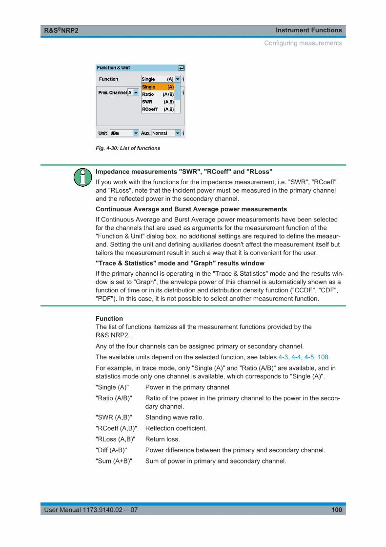
Instrument FunctionsR&S®NRP2
100User Manual 1173.9140.02 ─ 07
Fig. 4-30: List of functions
Impedance measurements "SWR", "RCoeff" and "RLoss"If you work with the functions for the impedance measurement, i.e. "SWR", "RCoeff"and "RLoss", note that the incident power must be measured in the primary channeland the reflected power in the secondary channel.Continuous Average and Burst Average power measurementsIf Continuous Average and Burst Average power measurements have been selectedfor the channels that are used as arguments for the measurement function of the"Function & Unit" dialog box, no additional settings are required to define the measur-and. Setting the unit and defining auxiliaries doesn't affect the measurement itself buttailors the measurement result in such a way that it is convenient for the user."Trace & Statistics" mode and "Graph" results windowIf the primary channel is operating in the "Trace & Statistics" mode and the results win-dow is set to "Graph", the envelope power of this channel is automatically shown as afunction of time or in its distribution and distribution density function ("CCDF", "CDF","PDF"). In this case, it is not possible to select another measurement function.
FunctionThe list of functions itemizes all the measurement functions provided by theR&S NRP2.
Any of the four channels can be assigned primary or secondary channel.
The available units depend on the selected function, see tables 4-3, 4-4, 4-5, 108.
For example, in trace mode, only "Single (A)" and "Ratio (A/B)" are available, and instatistics mode only one channel is available, which corresponds to "Single (A)".
"Single (A)" Power in the primary channel
"Ratio (A/B)" Ratio of the power in the primary channel to the power in the secon-dary channel.
"SWR (A,B)" Standing wave ratio.
"RCoeff (A,B)" Reflection coefficient.
"RLoss (A,B)" Return loss.
"Diff (A-B)" Power difference between the primary and secondary channel.
"Sum (A+B)" Sum of power in primary and secondary channel.
Configuring measurements
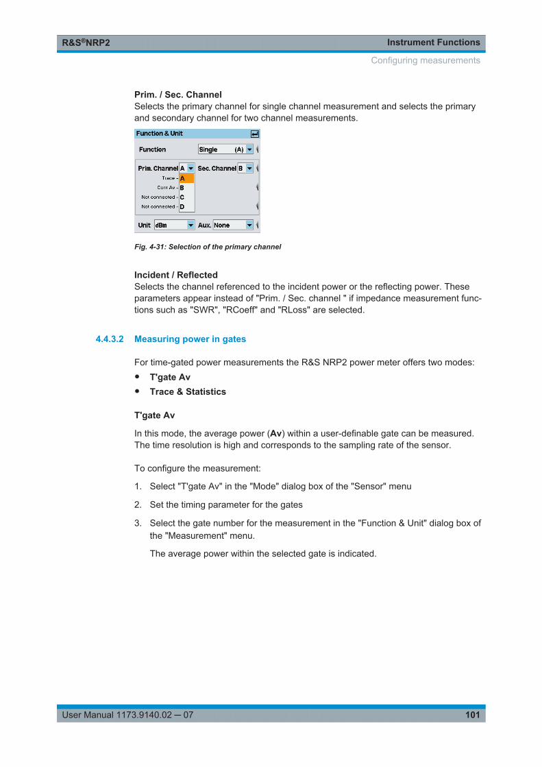
Instrument FunctionsR&S®NRP2
101User Manual 1173.9140.02 ─ 07
Prim. / Sec. ChannelSelects the primary channel for single channel measurement and selects the primaryand secondary channel for two channel measurements.
Fig. 4-31: Selection of the primary channel
Incident / ReflectedSelects the channel referenced to the incident power or the reflecting power. Theseparameters appear instead of "Prim. / Sec. channel " if impedance measurement func-tions such as "SWR", "RCoeff" and "RLoss" are selected.
4.4.3.2 Measuring power in gates
For time-gated power measurements the R&S NRP2 power meter offers two modes:● T'gate Av● Trace & Statistics
T'gate Av
In this mode, the average power (Av) within a user-definable gate can be measured.The time resolution is high and corresponds to the sampling rate of the sensor.
To configure the measurement:
1. Select "T'gate Av" in the "Mode" dialog box of the "Sensor" menu
2. Set the timing parameter for the gates
3. Select the gate number for the measurement in the "Function & Unit" dialog box ofthe "Measurement" menu.
The average power within the selected gate is indicated.
Configuring measurements
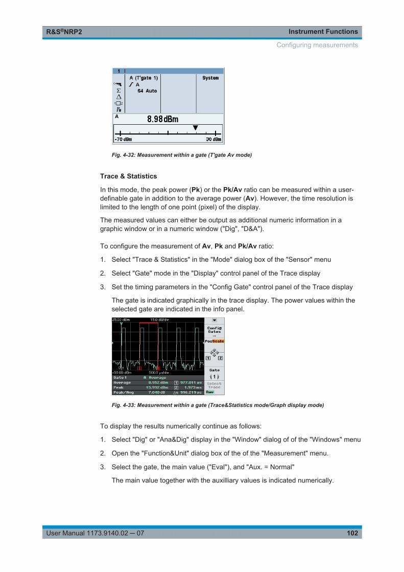
Instrument FunctionsR&S®NRP2
102User Manual 1173.9140.02 ─ 07
Fig. 4-32: Measurement within a gate (T'gate Av mode)
Trace & Statistics
In this mode, the peak power (Pk) or the Pk/Av ratio can be measured within a user-definable gate in addition to the average power (Av). However, the time resolution islimited to the length of one point (pixel) of the display.
The measured values can either be output as additional numeric information in agraphic window or in a numeric window ("Dig", "D&A").
To configure the measurement of Av, Pk and Pk/Av ratio:
1. Select "Trace & Statistics" in the "Mode" dialog box of the "Sensor" menu
2. Select "Gate" mode in the "Display" control panel of the Trace display
3. Set the timing parameters in the "Config Gate" control panel of the Trace display
The gate is indicated graphically in the trace display. The power values within theselected gate are indicated in the info panel.
Fig. 4-33: Measurement within a gate (Trace&Statistics mode/Graph display mode)
To display the results numerically continue as follows:
1. Select "Dig" or "Ana&Dig" display in the "Window" dialog of of the "Windows" menu
2. Open the "Function&Unit" dialog box of the of the "Measurement" menu.
3. Select the gate, the main value ("Eval"), and "Aux. = Normal"
The main value together with the auxilliary values is indicated numerically.
Configuring measurements
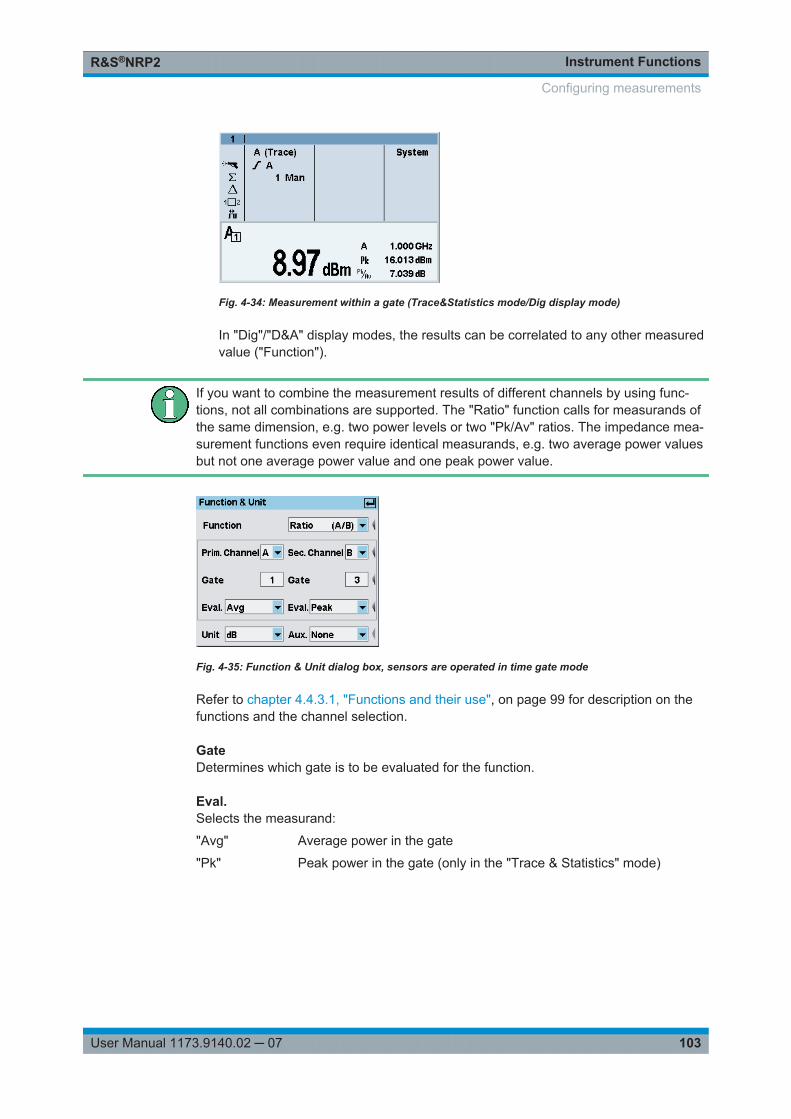
Instrument FunctionsR&S®NRP2
103User Manual 1173.9140.02 ─ 07
Fig. 4-34: Measurement within a gate (Trace&Statistics mode/Dig display mode)
In "Dig"/"D&A" display modes, the results can be correlated to any other measuredvalue ("Function").
If you want to combine the measurement results of different channels by using func-tions, not all combinations are supported. The "Ratio" function calls for measurands ofthe same dimension, e.g. two power levels or two "Pk/Av" ratios. The impedance mea-surement functions even require identical measurands, e.g. two average power valuesbut not one average power value and one peak power value.
Fig. 4-35: Function & Unit dialog box, sensors are operated in time gate mode
Refer to chapter 4.4.3.1, "Functions and their use", on page 99 for description on thefunctions and the channel selection.
GateDetermines which gate is to be evaluated for the function.
Eval.Selects the measurand:
"Avg" Average power in the gate
"Pk" Peak power in the gate (only in the "Trace & Statistics" mode)
Configuring measurements
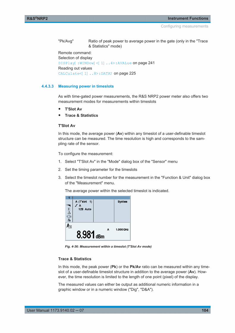
Instrument FunctionsR&S®NRP2
104User Manual 1173.9140.02 ─ 07
"Pk/Avg" Ratio of peak power to average power in the gate (only in the "Trace& Statistics" mode)
Remote command: Selection of displayDISPlay[:WINDow]<[1]..4>:AVALue on page 241Reading out valuesCALCulate<[1]..8>:DATA? on page 225
4.4.3.3 Measuring power in timeslots
As with time-gated power measurements, the R&S NRP2 power meter also offers twomeasurement modes for measurements within timeslots
● T'Slot Av● Trace & Statistics
T'Slot Av
In this mode, the average power (Av) within any timeslot of a user-definable timeslotstructure can be measured. The time resolution is high and corresponds to the sam-pling rate of the sensor.
To configure the measurement:
1. Select "T'Slot Av" in the "Mode" dialog box of the "Sensor" menu
2. Set the timing parameter for the timeslots
3. Select the timeslot number for the measurement in the "Function & Unit" dialog boxof the "Measurement" menu.
The average power within the selected timeslot is indicated.
Fig. 4-36: Measurement within a timeslot (T'Slot Av mode)
Trace & Statistics
In this mode, the peak power (Pk) or the Pk/Av ratio can be measured within any time-slot of a user-definable timeslot structure in addition to the average power (Av). How-ever, the time resolution is limited to the length of one point (pixel) of the display.
The measured values can either be output as additional numeric information in agraphic window or in a numeric window ("Dig", "D&A").
Configuring measurements
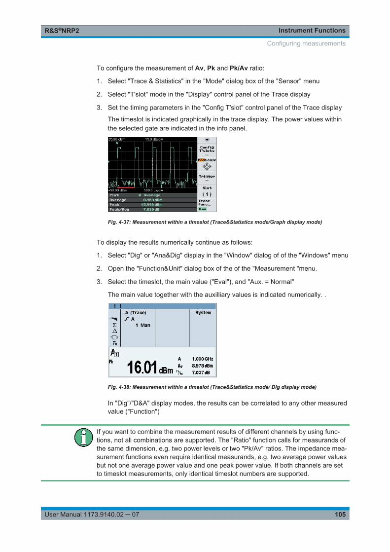
Instrument FunctionsR&S®NRP2
105User Manual 1173.9140.02 ─ 07
To configure the measurement of Av, Pk and Pk/Av ratio:
1. Select "Trace & Statistics" in the "Mode" dialog box of the "Sensor" menu
2. Select "T'slot" mode in the "Display" control panel of the Trace display
3. Set the timing parameters in the "Config T'slot" control panel of the Trace display
The timeslot is indicated graphically in the trace display. The power values withinthe selected gate are indicated in the info panel.
Fig. 4-37: Measurement within a timeslot (Trace&Statistics mode/Graph display mode)
To display the results numerically continue as follows:
1. Select "Dig" or "Ana&Dig" display in the "Window" dialog of of the "Windows" menu
2. Open the "Function&Unit" dialog box of the of the "Measurement "menu.
3. Select the timeslot, the main value ("Eval"), and "Aux. = Normal"
The main value together with the auxilliary values is indicated numerically. .
Fig. 4-38: Measurement within a timeslot (Trace&Statistics mode/ Dig display mode)
In "Dig"/"D&A" display modes, the results can be correlated to any other measuredvalue ("Function")
If you want to combine the measurement results of different channels by using func-tions, not all combinations are supported. The "Ratio" function calls for measurands ofthe same dimension, e.g. two power levels or two "Pk/Av" ratios. The impedance mea-surement functions even require identical measurands, e.g. two average power valuesbut not one average power value and one peak power value. If both channels are setto timeslot measurements, only identical timeslot numbers are supported.
Configuring measurements
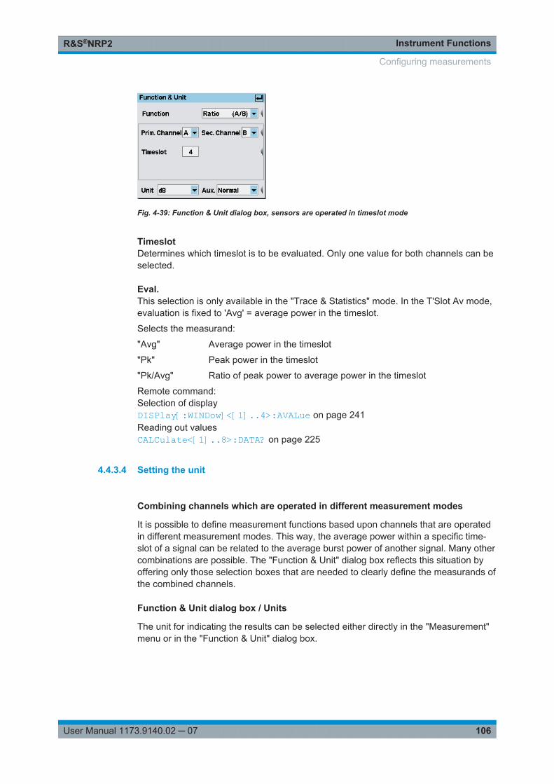
Instrument FunctionsR&S®NRP2
106User Manual 1173.9140.02 ─ 07
Fig. 4-39: Function & Unit dialog box, sensors are operated in timeslot mode
TimeslotDetermines which timeslot is to be evaluated. Only one value for both channels can beselected.
Eval.This selection is only available in the "Trace & Statistics" mode. In the T'Slot Av mode,evaluation is fixed to 'Avg' = average power in the timeslot.
Selects the measurand:
"Avg" Average power in the timeslot
"Pk" Peak power in the timeslot
"Pk/Avg" Ratio of peak power to average power in the timeslot
Remote command: Selection of displayDISPlay[:WINDow]<[1]..4>:AVALue on page 241Reading out valuesCALCulate<[1]..8>:DATA? on page 225
4.4.3.4 Setting the unit
Combining channels which are operated in different measurement modes
It is possible to define measurement functions based upon channels that are operatedin different measurement modes. This way, the average power within a specific time-slot of a signal can be related to the average burst power of another signal. Many othercombinations are possible. The "Function & Unit" dialog box reflects this situation byoffering only those selection boxes that are needed to clearly define the measurands ofthe combined channels.
Function & Unit dialog box / Units
The unit for indicating the results can be selected either directly in the "Measurement"menu or in the "Function & Unit" dialog box.
Configuring measurements
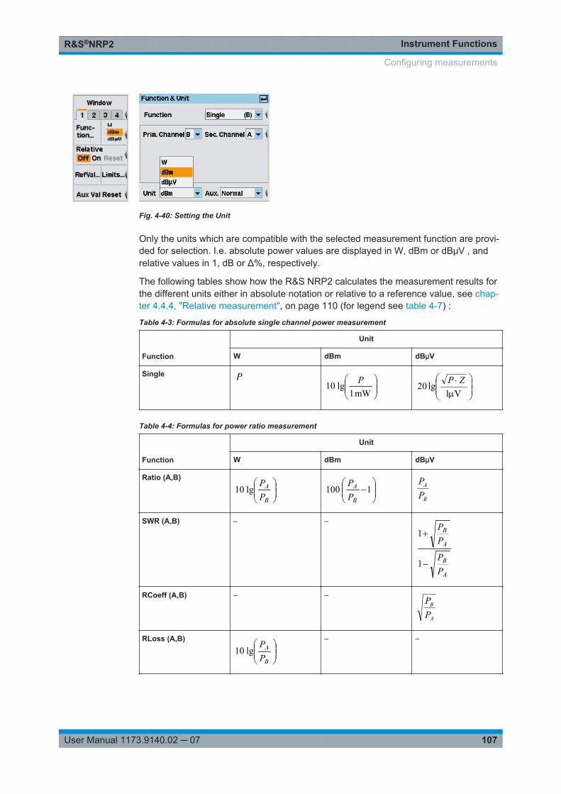
Instrument FunctionsR&S®NRP2
107User Manual 1173.9140.02 ─ 07
Fig. 4-40: Setting the Unit
Only the units which are compatible with the selected measurement function are provi-ded for selection. I.e. absolute power values are displayed in W, dBm or dBμV , andrelative values in 1, dB or Δ%, respectively.
The following tables show how the R&S NRP2 calculates the measurement results forthe different units either in absolute notation or relative to a reference value, see chap-ter 4.4.4, "Relative measurement", on page 110 (for legend see table 4-7) :
Table 4-3: Formulas for absolute single channel power measurement
Function
Unit
W dBm dBμV
Single P
mW1
lg10 P
V1
lg20 ZP
Table 4-4: Formulas for power ratio measurement
Function
Unit
W dBm dBμV
Ratio (A,B)
B
A
PP
lg10
1100
B
A
PP
B
A
PP
SWR (A,B) – –
A
B
A
B
PP
PP
1
1
RCoeff (A,B) – –
A
B
PP
RLoss (A,B)
B
A
PP
lg10– –
Configuring measurements
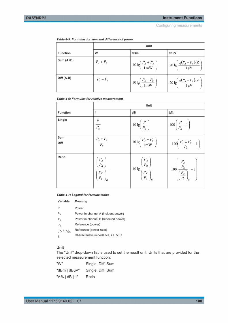
Instrument FunctionsR&S®NRP2
108User Manual 1173.9140.02 ─ 07
Table 4-5: Formulas for sum and difference of power
Function
Unit
W dBm dbμV
Sum (A+B) BA PP
mW1lg10 BA PP
Vμ1
lg20ZPP BA
Diff (A-B) BA PP
mW1lg10 BA PP
Vμ1
lg20ZPP BA
Table 4-6: Formulas for relative measurement
Function
Unit
1 dB Δ%
Single
RPP
RPPlg10
1100
RPP
Sum
Diff
R
BA
PPP
mW1lg10 BA PP
1100R
BA
PPP
Ratio
RY
X
B
A
PP
PP
RY
X
B
A
PP
PP
lg10
1100
RY
X
B
A
PPPP
Table 4-7: Legend for formula tables
Variable Meaning
P
PA
PB
PR
(PX / PY)R
Z
Power
Power in channel A (incident power)
Power in channel B (reflected power)
Reference (power)
Reference (power ratio)
Characteristic impedance, i.e. 50Ω
UnitThe "Unit" drop-down list is used to set the result unit. Units that are provided for theselected measurement function:
"W" Single, Diff, Sum
"dBm | dBμV" Single, Diff, Sum
"Δ% | dB | 1" Ratio
Configuring measurements
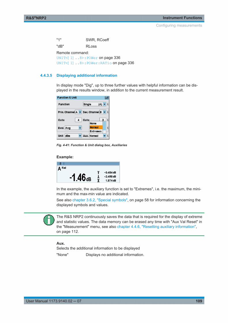
Instrument FunctionsR&S®NRP2
109User Manual 1173.9140.02 ─ 07
"1" SWR, RCoeff
"dB" RLoss
Remote command: UNIT<[1]..8>:POWer on page 336UNIT<[1]..8>:POWer:RATio on page 336
4.4.3.5 Displaying additional information
In display mode "Dig", up to three further values with helpful information can be dis-played in the results window, in addition to the current measurement result.
Fig. 4-41: Function & Unit dialog box, Auxiliaries
Example:
In the example, the auxiliary function is set to "Extremes", i.e. the maximum, the mini-mum and the max-min value are indicated.See also chapter 3.6.2, "Special symbols", on page 58 for information concerning thedisplayed symbols and values.
The R&S NRP2 continuously saves the data that is required for the display of extremeand statistic values. The data memory can be erased any time with "Aux Val Reset" inthe "Measurement" menu, see also chapter 4.4.6, "Resetting auxiliary information",on page 112.
Aux.Selects the additional information to be displayed
"None" Displays no additional information.
Configuring measurements
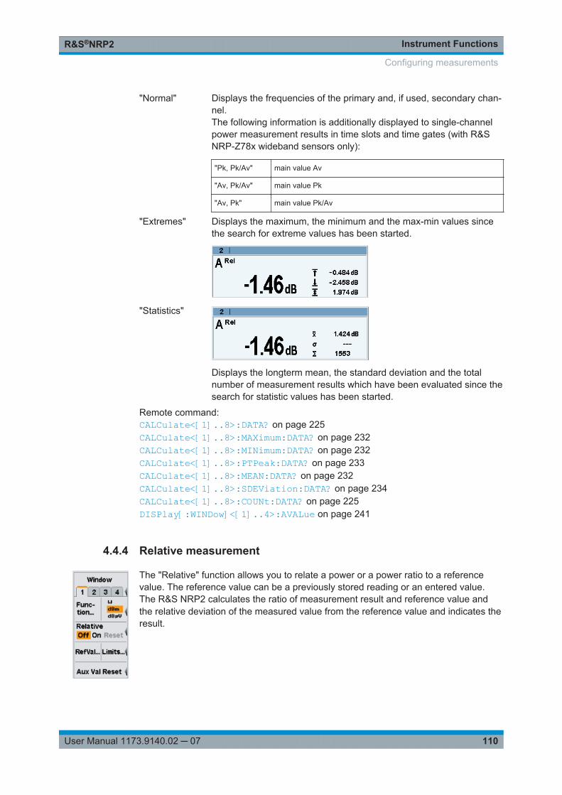
Instrument FunctionsR&S®NRP2
110User Manual 1173.9140.02 ─ 07
"Normal" Displays the frequencies of the primary and, if used, secondary chan-nel.The following information is additionally displayed to single-channelpower measurement results in time slots and time gates (with R&SNRP-Z78x wideband sensors only):
"Pk, Pk/Av" main value Av
"Av, Pk/Av" main value Pk
"Av, Pk" main value Pk/Av
"Extremes" Displays the maximum, the minimum and the max-min values sincethe search for extreme values has been started.
"Statistics"
Displays the longterm mean, the standard deviation and the totalnumber of measurement results which have been evaluated since thesearch for statistic values has been started.
Remote command: CALCulate<[1]..8>:DATA? on page 225CALCulate<[1]..8>:MAXimum:DATA? on page 232CALCulate<[1]..8>:MINimum:DATA? on page 232CALCulate<[1]..8>:PTPeak:DATA? on page 233CALCulate<[1]..8>:MEAN:DATA? on page 232CALCulate<[1]..8>:SDEViation:DATA? on page 234CALCulate<[1]..8>:COUNt:DATA? on page 225DISPlay[:WINDow]<[1]..4>:AVALue on page 241
4.4.4 Relative measurement
The "Relative" function allows you to relate a power or a power ratio to a referencevalue. The reference value can be a previously stored reading or an entered value.The R&S NRP2 calculates the ratio of measurement result and reference value andthe relative deviation of the measured value from the reference value and indicates theresult.
Configuring measurements

Instrument FunctionsR&S®NRP2
111User Manual 1173.9140.02 ─ 07
4.4.4.1 Relative
The "Relative" settings activate or deactivate relative power measurement, or assign ameasurement result as reference.
Off On ResetRelates a power or a power ratio to a reference value.
"Off" Absolute power measurement or measurement of the power ratio oftwo measurement channels using the "Ratio" function is performed.
"On" Relative power measurement or relative power ratio measurement.
"Reset" Assigns the current measurement result as reference value.
Remote command: CALCulate<[1]..8>:RELative:STATe on page 234CALCulate<[1]..8>:RELative[:MAGNitude]:AUTO on page 233
4.4.4.2 Setting the reference value manually
The reference value can be directly entered or edited using the "Reference Value" dia-log box. Open the dialog box with the "RefVal" softkey.
Fig. 4-42: Reference value dialog box
RefEnter a reference value or modify a previously set value.
Remote command: CALCulate<[1]..8>:RELative[:MAGNitude] on page 233
ResetThe current measurement result is transferred to the reference value memory of theactive window and is displayed. This function can also be started from the "Measure-ment" menu by using the "Reset" softkey.
Remote command: CALCulate<[1]..8>:RELative[:MAGNitude]:AUTO on page 233
4.4.5 Limit Monitoring
An upper and a lower limit for each window with digital ("Dig") or digital/analog ("D&A")result display can be set in the "Limits" dialog box. If either limit is violated, a warning isissued.
The warning may be one of the following:● The "LIMIT FAIL" message is displayed on the screen (always).
Configuring measurements
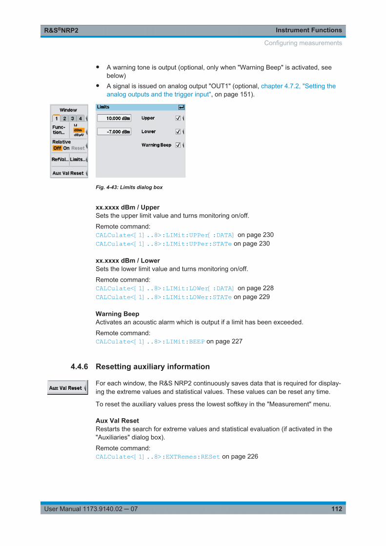
Instrument FunctionsR&S®NRP2
112User Manual 1173.9140.02 ─ 07
● A warning tone is output (optional, only when "Warning Beep" is activated, seebelow)
● A signal is issued on analog output "OUT1" (optional, chapter 4.7.2, "Setting theanalog outputs and the trigger input", on page 151).
Fig. 4-43: Limits dialog box
xx.xxxx dBm / UpperSets the upper limit value and turns monitoring on/off.
Remote command: CALCulate<[1]..8>:LIMit:UPPer[:DATA] on page 230CALCulate<[1]..8>:LIMit:UPPer:STATe on page 230
xx.xxxx dBm / LowerSets the lower limit value and turns monitoring on/off.
Remote command: CALCulate<[1]..8>:LIMit:LOWer[:DATA] on page 228CALCulate<[1]..8>:LIMit:LOWer:STATe on page 229
Warning BeepActivates an acoustic alarm which is output if a limit has been exceeded.
Remote command: CALCulate<[1]..8>:LIMit:BEEP on page 227
4.4.6 Resetting auxiliary information
For each window, the R&S NRP2 continuously saves data that is required for display-ing the extreme values and statistical values. These values can be reset any time.
To reset the auxiliary values press the lowest softkey in the "Measurement" menu.
Aux Val ResetRestarts the search for extreme values and statistical evaluation (if activated in the"Auxiliaries" dialog box).
Remote command: CALCulate<[1]..8>:EXTRemes:RESet on page 226
Configuring measurements
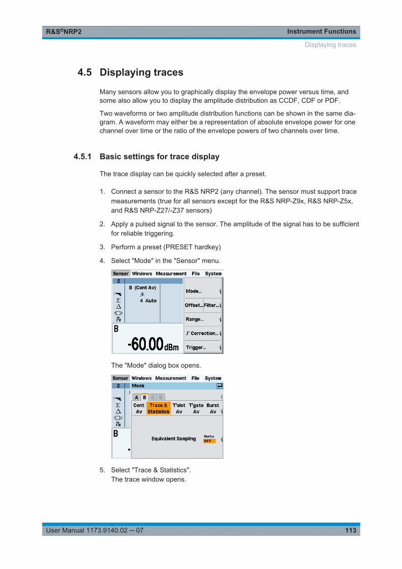
Instrument FunctionsR&S®NRP2
113User Manual 1173.9140.02 ─ 07
4.5 Displaying traces
Many sensors allow you to graphically display the envelope power versus time, andsome also allow you to display the amplitude distribution as CCDF, CDF or PDF.
Two waveforms or two amplitude distribution functions can be shown in the same dia-gram. A waveform may either be a representation of absolute envelope power for onechannel over time or the ratio of the envelope powers of two channels over time.
4.5.1 Basic settings for trace display
The trace display can be quickly selected after a preset.
1. Connect a sensor to the R&S NRP2 (any channel). The sensor must support tracemeasurements (true for all sensors except for the R&S NRP-Z9x, R&S NRP-Z5x,and R&S NRP-Z27/-Z37 sensors)
2. Apply a pulsed signal to the sensor. The amplitude of the signal has to be sufficientfor reliable triggering.
3. Perform a preset (PRESET hardkey)
4. Select "Mode" in the "Sensor" menu.
The "Mode" dialog box opens.
5. Select "Trace & Statistics".The trace window opens.
Displaying traces
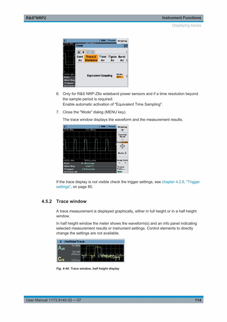
Instrument FunctionsR&S®NRP2
114User Manual 1173.9140.02 ─ 07
6. Only for R&S NRP-Z8x wideband power sensors and if a time resolution beyondthe sample period is required:Enable automatic activation of "Equivalent Time Sampling".
7. Close the "Mode" dialog (MENU key).
The trace window displays the waveform and the measurement results.
If the trace display is not visible check the trigger settings, see chapter 4.2.6, "Triggersettings", on page 85.
4.5.2 Trace window
A trace measurement is displayed graphically, either in full height or in a half heightwindow.
In half height window the meter shows the waveform(s) and an info panel indicatingselected measurement results or instrument settings. Control elements to directlychange the settings are not available.
Fig. 4-44: Trace window, half height display
Displaying traces
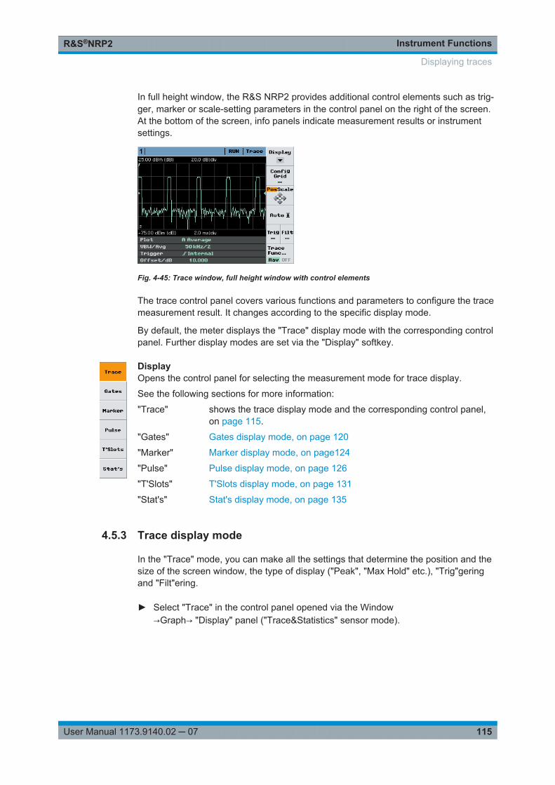
Instrument FunctionsR&S®NRP2
115User Manual 1173.9140.02 ─ 07
In full height window, the R&S NRP2 provides additional control elements such as trig-ger, marker or scale-setting parameters in the control panel on the right of the screen.At the bottom of the screen, info panels indicate measurement results or instrumentsettings.
Fig. 4-45: Trace window, full height window with control elements
The trace control panel covers various functions and parameters to configure the tracemeasurement result. It changes according to the specific display mode.
By default, the meter displays the "Trace" display mode with the corresponding controlpanel. Further display modes are set via the "Display" softkey.
DisplayOpens the control panel for selecting the measurement mode for trace display.
See the following sections for more information:
"Trace" shows the trace display mode and the corresponding control panel,on page 115.
"Gates" Gates display mode, on page 120
"Marker" Marker display mode, on page124
"Pulse" Pulse display mode, on page 126
"T'Slots" T'Slots display mode, on page 131
"Stat's" Stat's display mode, on page 135
4.5.3 Trace display mode
In the "Trace" mode, you can make all the settings that determine the position and thesize of the screen window, the type of display ("Peak", "Max Hold" etc.), "Trig"geringand "Filt"ering.
► Select "Trace" in the control panel opened via the Window→Graph→ "Display" panel ("Trace&Statistics" sensor mode).
Displaying traces
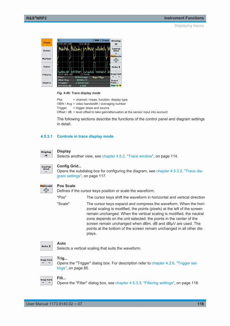
Instrument FunctionsR&S®NRP2
116User Manual 1173.9140.02 ─ 07
Fig. 4-46: Trace display mode
Plot = channel / meas. function; display typeVBW / Avg = video bandwidth / averaging numberTrigger = trigger slope and sourceOffset / dB = level offset to take gain/attenuation at the sensor input into account
The following sections describe the functions of the control panel and diagram settingsin detail.
4.5.3.1 Controls in trace display mode
DisplaySelects another view, see chapter 4.5.2, "Trace window", on page 114.
Config Grid...Opens the subdialog box for configuring the diagram, see chapter 4.5.3.2, "Trace dia-gram settings", on page 117.
Pos ScaleDefines if the cursor keys position or scale the waveform.
"Pos" The cursor keys shift the waveform in horizontal and vertical direction
"Scale" The cursor keys expand and compress the waveform. When the hori-zontal scaling is modified, the points (pixels) at the left of the screenremain unchanged. When the vertical scaling is modified, the neutralzone depends on the unit selected: the points in the center of thescreen remain unchanged when dBm, dB and dBµV are used. Thepoints at the bottom of the screen remain unchanged in all other dis-plays.
AutoSelects a vertical scaling that suits the waveform.
Trig...Opens the "Trigger" dialog box. For description refer to chapter 4.2.6, "Trigger set-tings", on page 85.
Filt...Opens the "Filter" dialog box, see chapter 4.5.3.3, "Filtering settings", on page 118.
Displaying traces
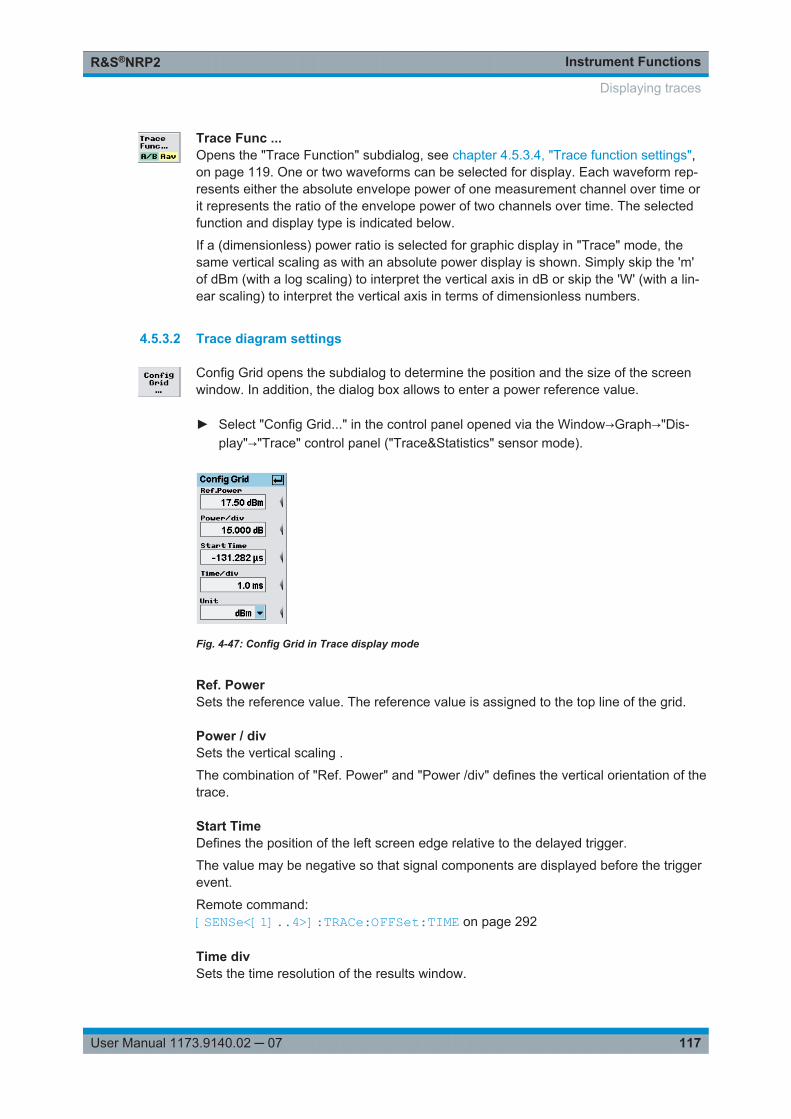
Instrument FunctionsR&S®NRP2
117User Manual 1173.9140.02 ─ 07
Trace Func ...Opens the "Trace Function" subdialog, see chapter 4.5.3.4, "Trace function settings",on page 119. One or two waveforms can be selected for display. Each waveform rep-resents either the absolute envelope power of one measurement channel over time orit represents the ratio of the envelope power of two channels over time. The selectedfunction and display type is indicated below.
If a (dimensionless) power ratio is selected for graphic display in "Trace" mode, thesame vertical scaling as with an absolute power display is shown. Simply skip the 'm'of dBm (with a log scaling) to interpret the vertical axis in dB or skip the 'W' (with a lin-ear scaling) to interpret the vertical axis in terms of dimensionless numbers.
4.5.3.2 Trace diagram settings
Config Grid opens the subdialog to determine the position and the size of the screenwindow. In addition, the dialog box allows to enter a power reference value.
► Select "Config Grid..." in the control panel opened via the Window→Graph→"Dis-play"→"Trace" control panel ("Trace&Statistics" sensor mode).
Fig. 4-47: Config Grid in Trace display mode
Ref. PowerSets the reference value. The reference value is assigned to the top line of the grid.
Power / divSets the vertical scaling .
The combination of "Ref. Power" and "Power /div" defines the vertical orientation of thetrace.
Start TimeDefines the position of the left screen edge relative to the delayed trigger.
The value may be negative so that signal components are displayed before the triggerevent.
Remote command: [SENSe<[1]..4>]:TRACe:OFFSet:TIME on page 292
Time divSets the time resolution of the results window.
Displaying traces
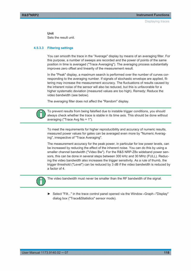
Instrument FunctionsR&S®NRP2
118User Manual 1173.9140.02 ─ 07
UnitSets the result unit.
4.5.3.3 Filtering settings
You can smooth the trace in the "Average" display by means of an averaging filter. Forthis purpose, a number of sweeps are recorded and the power of points of the sameposition in time is averaged ("Trace Averaging"). The averaging process substantiallyimproves zero offset and linearity of the measurement result.
In the "Peak" display, a maximum search is performed over the number of curves cor-responding to the averaging number. If signals of stochastic envelope are applied, fil-tering may increase the measurement accuracy. The fluctuations of results caused bythe inherent noise of the sensor will also be reduced, but this is unfavorable for ahigher systematic deviation (measured values are too high). Remedy: Reduce thevideo bandwidth (see below).
The averaging filter does not affect the "Random" display.
To prevent results from being falsified due to instable trigger conditions, you shouldalways check whether the trace is stable in its time axis. This should be done withoutaveraging ("Trace Avg No = 1").
To meet the requirements for higher reproducibility and accuracy of numeric results,measured power values for gates can be averaged even more by "Numeric Averag-ing", irrespective of "Trace Averaging".
The measurement accuracy for the peak power, in particular for low power levels, canbe increased by reducing the effect of the inherent noise. You can do this by using asmaller channel bandwidth ("Video Bw"). For the R&S NRP-Z8x wideband power sen-sors, this can be done in several steps between 300 kHz and 30 MHz (FULL). Reduc-ing the video bandwidth also increases the trigger sensitivity. As a rule of thumb, thetrigger threshold ("Level") can be reduced by 3 dB if the video bandwidth is reduced bya factor of 4.
The video bandwidth must never be smaller than the RF bandwidth of the signal.
► Select "Filt..." in the trace control panel opened via the Window→Graph→"Display"dialog box ("Trace&Statistics" sensor mode).
Displaying traces
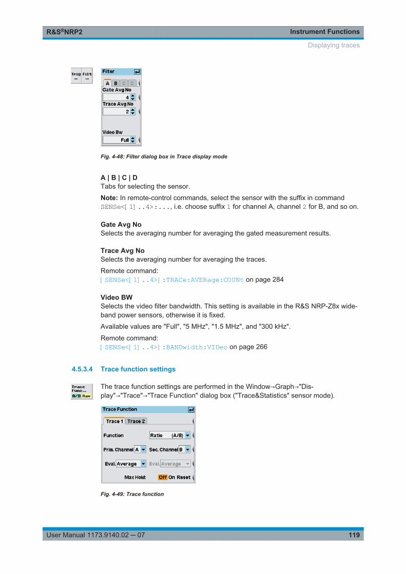
Instrument FunctionsR&S®NRP2
119User Manual 1173.9140.02 ─ 07
Fig. 4-48: Filter dialog box in Trace display mode
A | B | C | DTabs for selecting the sensor.
Note: In remote-control commands, select the sensor with the suffix in commandSENSe<[1]..4>:..., i.e. choose suffix 1 for channel A, channel 2 for B, and so on.
Gate Avg NoSelects the averaging number for averaging the gated measurement results.
Trace Avg NoSelects the averaging number for averaging the traces.
Remote command: [SENSe<[1]..4>]:TRACe:AVERage:COUNt on page 284
Video BWSelects the video filter bandwidth. This setting is available in the R&S NRP-Z8x wide-band power sensors, otherwise it is fixed.
Available values are "Full", "5 MHz", "1.5 MHz", and "300 kHz".
Remote command: [SENSe<[1]..4>]:BANDwidth:VIDeo on page 266
4.5.3.4 Trace function settings
The trace function settings are performed in the Window→Graph→"Dis-play"→"Trace"→"Trace Function" dialog box ("Trace&Statistics" sensor mode).
Fig. 4-49: Trace function
Displaying traces
Instrument FunctionsR&S®NRP2
120User Manual 1173.9140.02 ─ 07
Trace 1 / 2Selects the trace (waveform) to be configured.
Up to two traces can be selected. This is also true if only one measurement channel(sensor) is present. In this case, one trace for example can represent the averageenvelope power and the other trace the peak or random power (available for the R&SNRP-Z8x wideband sensors only).
FunctionSelects the measurement function for the "Trace" mode. Only "Single" and "Ratio"functions are available for trace measurements. Refer to "Function" on page 100 fordescription.
Note: It is essential that the sensors of both channels support trace measurement, ifthe "Ratio" function is selected.
Prim. / Sec. ChannelSelects the primary and secondary channel.
Eval.Select the type of display. Since each display point (pixel) represents a time intervaland thus usually many samples, the R&S NRP-Z8x wideband power sensors allow youto select what is to be displayed.
"Average" Average power value, resulting in a flicker-free display and smoothtrace.Note: Average is fixed for all multipath power sensors.
"Random" Power of a randomly selected sample, i.e. a realistic display with sig-nal details.
"Peak" Highest power measured (peak power).
Max. HoldDisplays the highest value measured for each point (pixel) of the selected display type("Average", "Random ", "Peak").
"On / Off" Starts/stops "Max Hold".
"Reset" Resets the display and restarts recording.
4.5.4 Gates display mode
In the "Gate" mode, four separately configurable gates for signal evaluation are availa-ble. The active gate is indicated in the window, the info panel shows the measurementresults and borders for this gate and the selected trace (waveform) . The settings for"Trig"gering, "Filt"ering, "Function", and "Unit" are taken from the "Trace" display modeand cannot be changed.
► Select "Gates" in the control panel opened via the Window→Graph→"Display" dia-log box ("Trace&Statistics" sensor mode).
Displaying traces
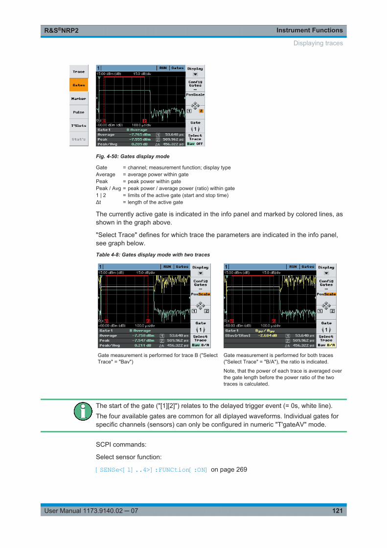
Instrument FunctionsR&S®NRP2
121User Manual 1173.9140.02 ─ 07
Fig. 4-50: Gates display mode
Gate = channel; measurement function; display typeAverage = average power within gatePeak = peak power within gatePeak / Avg = peak power / average power (ratio) within gate1 | 2 = limits of the active gate (start and stop time)Δt = length of the active gate
The currently active gate is indicated in the info panel and marked by colored lines, asshown in the graph above.
"Select Trace" defines for which trace the parameters are indicated in the info panel,see graph below.
Table 4-8: Gates display mode with two traces
Gate measurement is performed for trace B ("SelectTrace" = "Bav")
Gate measurement is performed for both traces("Select Trace" = "B/A"), the ratio is indicated.
Note, that the power of each trace is averaged overthe gate length before the power ratio of the twotraces is calculated.
The start of the gate ("[1][2]") relates to the delayed trigger event (= 0s, white line).The four available gates are common for all diplayed waveforms. Individual gates forspecific channels (sensors) can only be configured in numeric "T'gateAV" mode.
SCPI commands:
Select sensor function:
[SENSe<[1]..4>]:FUNCtion[:ON] on page 269
Displaying traces
Instrument FunctionsR&S®NRP2
122User Manual 1173.9140.02 ─ 07
Define calculation of measurement result:
CALCulate<[1]..8>:FEED<[1]|2> on page 226
Read result:
FETCh? on page 211
4.5.4.1 Measurement results
The measured values for the selected gate and trace (waveform) are indicated in theinfo panel below the graph (see also "Select Trace ..." on page 123).
Average / Peak / Peak/AvgAverage power, peak power and the ratio peak power to average power.
"1 | 2" Start and stop time of gate.
"Δt" Duration of gate.
Remote command: Configuring measurement:CALCulate<[1]..8>:FEED<[1]|2> on page 226Retrieving results:FETCh? on page 211
4.5.4.2 Controls in gates display mode
DisplaySelects another view, see chapter 4.5.2, "Trace window", on page 114.
Config Gates ...Open the subdialog to configure the four available gates, see chapter 4.5.4.3, "Gatediagram settings", on page 123.
Pos ScaleDefines if the cursor keys position or scale the waveform.
"Pos" The cursor keys shift the waveform in horizontal and vertical direction
"Scale" The cursor keys expand and compress the waveform. When the hori-zontal scaling is modified, the points (pixels) at the left of the screenremain unchanged. When the vertical scaling is modified, the neutralzone depends on the unit selected: the points in the center of thescreen remain unchanged when dBm, dB and dBµV are used. Thepoints at the bottom of the screen remain unchanged in all other dis-plays.
[1] [2] [3] [4]Switches the the function of the cursor keys to altering the borders of a gate.
"[1] [2]" Shifts the start and stop time.
Displaying traces
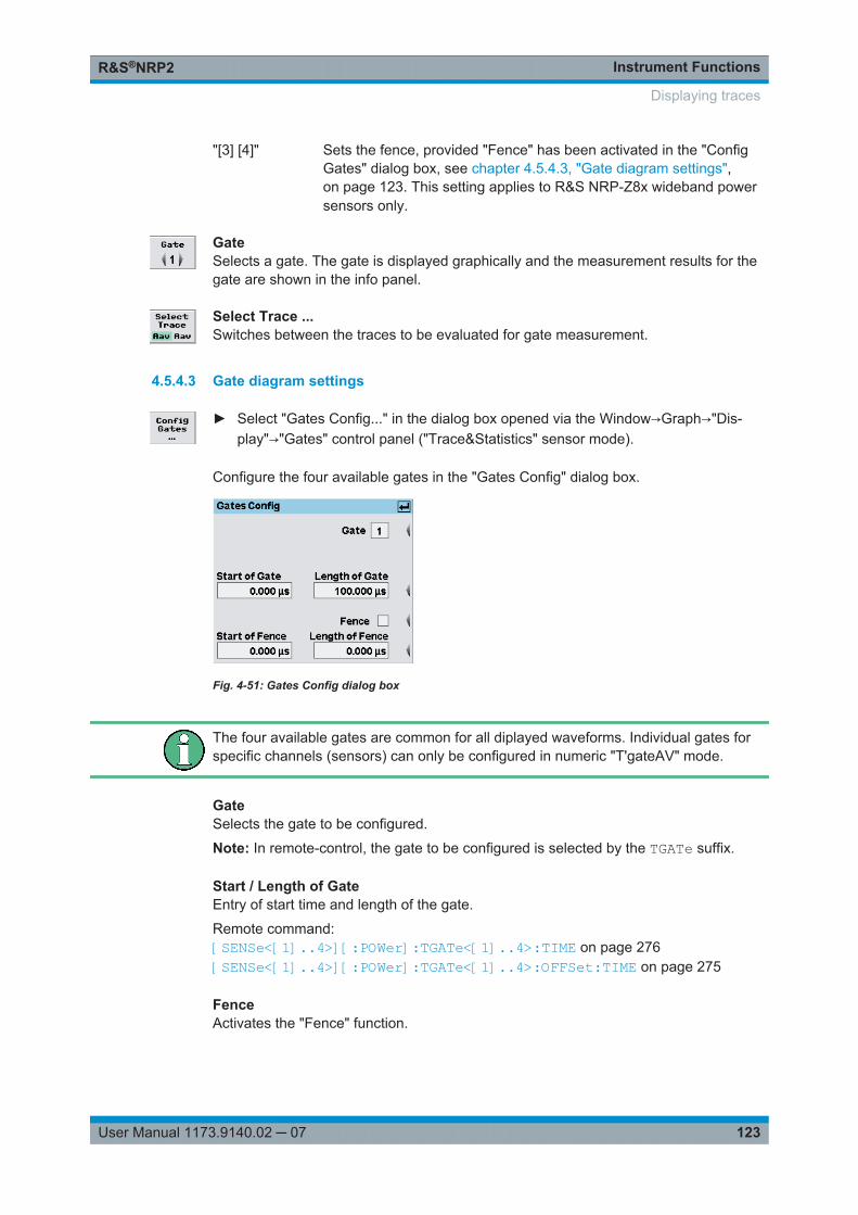
Instrument FunctionsR&S®NRP2
123User Manual 1173.9140.02 ─ 07
"[3] [4]" Sets the fence, provided "Fence" has been activated in the "ConfigGates" dialog box, see chapter 4.5.4.3, "Gate diagram settings",on page 123. This setting applies to R&S NRP-Z8x wideband powersensors only.
GateSelects a gate. The gate is displayed graphically and the measurement results for thegate are shown in the info panel.
Select Trace ...Switches between the traces to be evaluated for gate measurement.
4.5.4.3 Gate diagram settings
► Select "Gates Config..." in the dialog box opened via the Window→Graph→"Dis-play"→"Gates" control panel ("Trace&Statistics" sensor mode).
Configure the four available gates in the "Gates Config" dialog box.
Fig. 4-51: Gates Config dialog box
The four available gates are common for all diplayed waveforms. Individual gates forspecific channels (sensors) can only be configured in numeric "T'gateAV" mode.
GateSelects the gate to be configured.
Note: In remote-control, the gate to be configured is selected by the TGATe suffix.
Start / Length of GateEntry of start time and length of the gate.
Remote command: [SENSe<[1]..4>][:POWer]:TGATe<[1]..4>:TIME on page 276[SENSe<[1]..4>][:POWer]:TGATe<[1]..4>:OFFSet:TIME on page 275
FenceActivates the "Fence" function.
Displaying traces
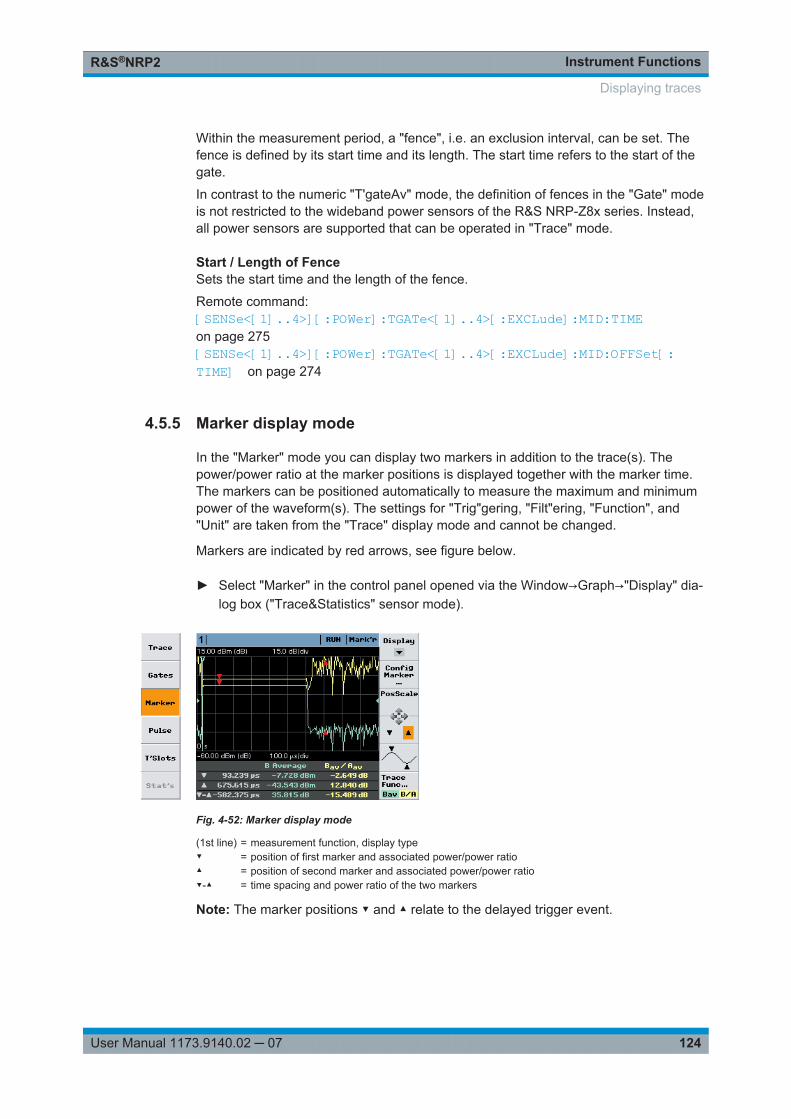
Instrument FunctionsR&S®NRP2
124User Manual 1173.9140.02 ─ 07
Within the measurement period, a "fence", i.e. an exclusion interval, can be set. Thefence is defined by its start time and its length. The start time refers to the start of thegate.
In contrast to the numeric "T'gateAv" mode, the definition of fences in the "Gate" modeis not restricted to the wideband power sensors of the R&S NRP-Z8x series. Instead,all power sensors are supported that can be operated in "Trace" mode.
Start / Length of FenceSets the start time and the length of the fence.
Remote command: [SENSe<[1]..4>][:POWer]:TGATe<[1]..4>[:EXCLude]:MID:TIMEon page 275[SENSe<[1]..4>][:POWer]:TGATe<[1]..4>[:EXCLude]:MID:OFFSet[:TIME] on page 274
4.5.5 Marker display mode
In the "Marker" mode you can display two markers in addition to the trace(s). Thepower/power ratio at the marker positions is displayed together with the marker time.The markers can be positioned automatically to measure the maximum and minimumpower of the waveform(s). The settings for "Trig"gering, "Filt"ering, "Function", and"Unit" are taken from the "Trace" display mode and cannot be changed.
Markers are indicated by red arrows, see figure below.
► Select "Marker" in the control panel opened via the Window→Graph→"Display" dia-log box ("Trace&Statistics" sensor mode).
Fig. 4-52: Marker display mode
(1st line) = measurement function, display type▼ = position of first marker and associated power/power ratio▲ = position of second marker and associated power/power ratio▼-▲ = time spacing and power ratio of the two markers
Note: The marker positions ▼ and ▲ relate to the delayed trigger event.
Displaying traces
Instrument FunctionsR&S®NRP2
125User Manual 1173.9140.02 ─ 07
4.5.5.1 Controls in Marker display mode
DisplaySelects another view, see chapter 4.5.2, "Trace window", on page 114.
Config Marker...Opens the subdialog to manually define the marker positions, see chapter 4.5.5.2,"Marker diagram settings", on page 125.
Pos ScaleDefines if the cursor keys position or scale the waveform.
"Pos" The cursor keys shift the waveform in horizontal and vertical direction
"Scale" The cursor keys expand and compress the waveform. When the hori-zontal scaling is modified, the points (pixels) at the left of the screenremain unchanged. When the vertical scaling is modified, the neutralzone depends on the unit selected: the points in the center of thescreen remain unchanged when dBm, dB and dBµV are used. Thepoints at the bottom of the screen remain unchanged in all other dis-plays.
▼ / ▲Defines the active marker which can be positioned by means of the cursor keys.
(Max/Min marker position)Sets the two markers to the extreme values of the selected trace each time the key ispressed. If two traces are active, pressing the left side of the softkey selects trace 1and pressing the right side selcets trace 2.
Trace Func...Opens the "Trace Function" dialog box, see chapter 4.5.3.4, "Trace function settings",on page 119 .
4.5.5.2 Marker diagram settings
► Open the "Marker Config" dialog box open via the Window→Graph→"Dis-play"→"Marker" control panel ("Trace&Statistics" sensor mode).
Displaying traces
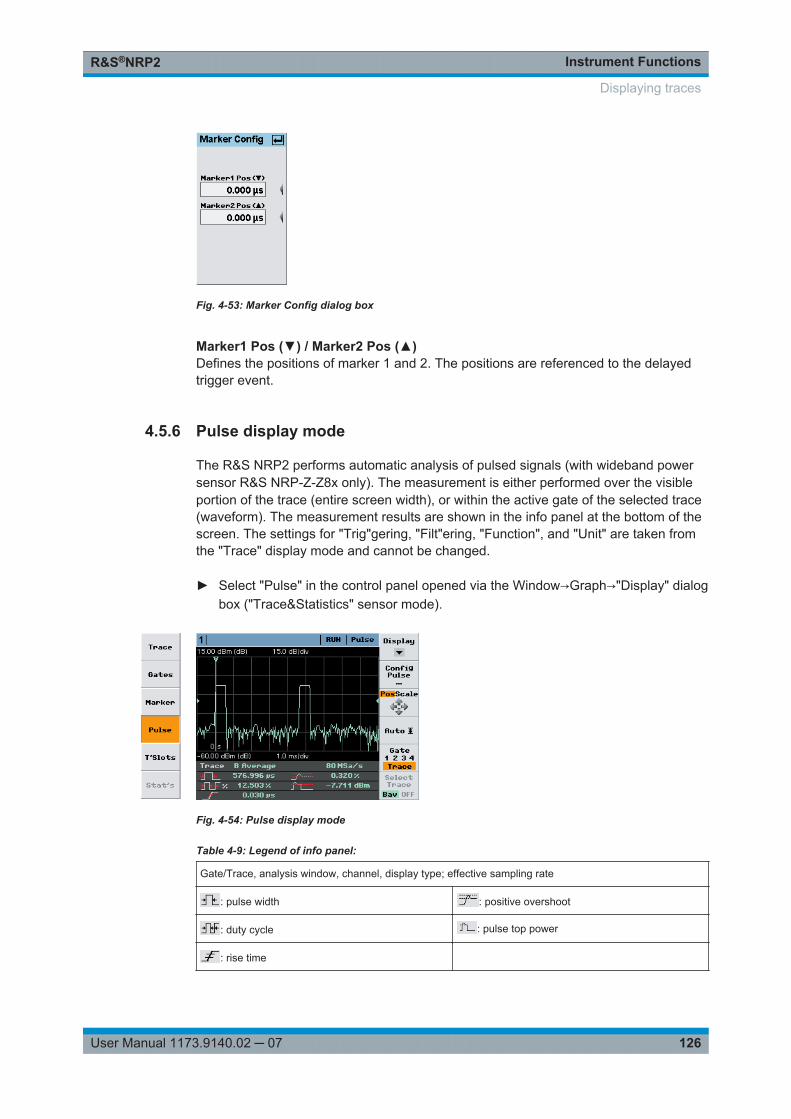
Instrument FunctionsR&S®NRP2
126User Manual 1173.9140.02 ─ 07
Fig. 4-53: Marker Config dialog box
Marker1 Pos (▼) / Marker2 Pos (▲)Defines the positions of marker 1 and 2. The positions are referenced to the delayedtrigger event.
4.5.6 Pulse display mode
The R&S NRP2 performs automatic analysis of pulsed signals (with wideband powersensor R&S NRP-Z-Z8x only). The measurement is either performed over the visibleportion of the trace (entire screen width), or within the active gate of the selected trace(waveform). The measurement results are shown in the info panel at the bottom of thescreen. The settings for "Trig"gering, "Filt"ering, "Function", and "Unit" are taken fromthe "Trace" display mode and cannot be changed.
► Select "Pulse" in the control panel opened via the Window→Graph→"Display" dialogbox ("Trace&Statistics" sensor mode).
Fig. 4-54: Pulse display mode
Table 4-9: Legend of info panel:
Gate/Trace, analysis window, channel, display type; effective sampling rate
: pulse width : positive overshoot
: duty cycle : pulse top power
: rise time
Displaying traces
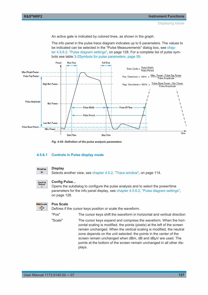
Instrument FunctionsR&S®NRP2
127User Manual 1173.9140.02 ─ 07
An active gate is indicated by colored lines, as shown in the graph.
The info panel in the pulse trace diagram indicates up to 6 parameters. The values tobe indicated can be selected in the "Pulse Measurements" dialog box, see chap-ter 4.5.6.2, "Pulse diagram settings", on page 128. For a complete list of pulse sym-bols see table 3-2Symbols for pulse parameters, page 59.
Fig. 4-55: Definition of the pulse analysis parameters
4.5.6.1 Controls in Pulse display mode
DisplaySelects another view, see chapter 4.5.2, "Trace window", on page 114.
Config Pulse...Opens the subdialog to configure the pulse analysis and to select the power/timeparameters for the info panel display, see chapter 4.5.6.2, "Pulse diagram settings",on page 128.
Pos ScaleDefines if the cursor keys position or scale the waveform.
"Pos" The cursor keys shift the waveform in horizontal and vertical direction
"Scale" The cursor keys expand and compress the waveform. When the hori-zontal scaling is modified, the points (pixels) at the left of the screenremain unchanged. When the vertical scaling is modified, the neutralzone depends on the unit selected: the points in the center of thescreen remain unchanged when dBm, dB and dBµV are used. Thepoints at the bottom of the screen remain unchanged in all other dis-plays.
Displaying traces
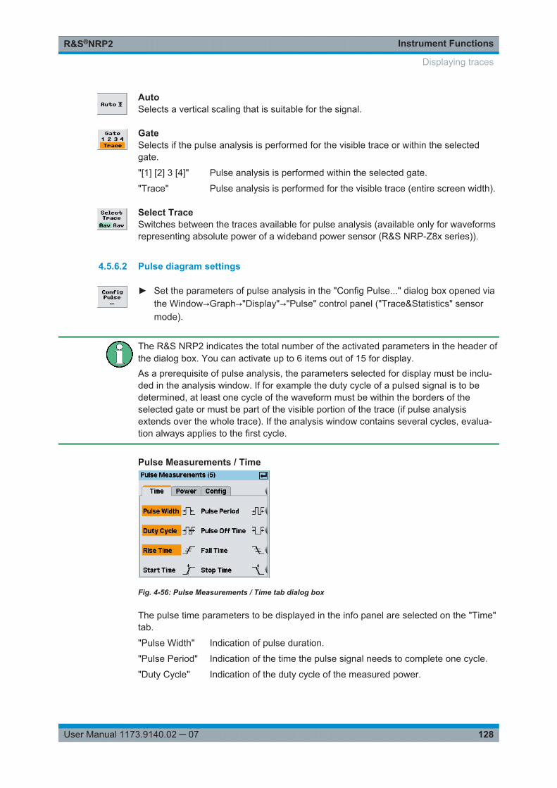
Instrument FunctionsR&S®NRP2
128User Manual 1173.9140.02 ─ 07
AutoSelects a vertical scaling that is suitable for the signal.
GateSelects if the pulse analysis is performed for the visible trace or within the selectedgate.
"[1] [2] 3 [4]" Pulse analysis is performed within the selected gate.
"Trace" Pulse analysis is performed for the visible trace (entire screen width).
Select TraceSwitches between the traces available for pulse analysis (available only for waveformsrepresenting absolute power of a wideband power sensor (R&S NRP-Z8x series)).
4.5.6.2 Pulse diagram settings
► Set the parameters of pulse analysis in the "Config Pulse..." dialog box opened viathe Window→Graph→"Display"→"Pulse" control panel ("Trace&Statistics" sensormode).
The R&S NRP2 indicates the total number of the activated parameters in the header ofthe dialog box. You can activate up to 6 items out of 15 for display.As a prerequisite of pulse analysis, the parameters selected for display must be inclu-ded in the analysis window. If for example the duty cycle of a pulsed signal is to bedetermined, at least one cycle of the waveform must be within the borders of theselected gate or must be part of the visible portion of the trace (if pulse analysisextends over the whole trace). If the analysis window contains several cycles, evalua-tion always applies to the first cycle.
Pulse Measurements / Time
Fig. 4-56: Pulse Measurements / Time tab dialog box
The pulse time parameters to be displayed in the info panel are selected on the "Time"tab.
"Pulse Width" Indication of pulse duration.
"Pulse Period" Indication of the time the pulse signal needs to complete one cycle.
"Duty Cycle" Indication of the duty cycle of the measured power.
Displaying traces
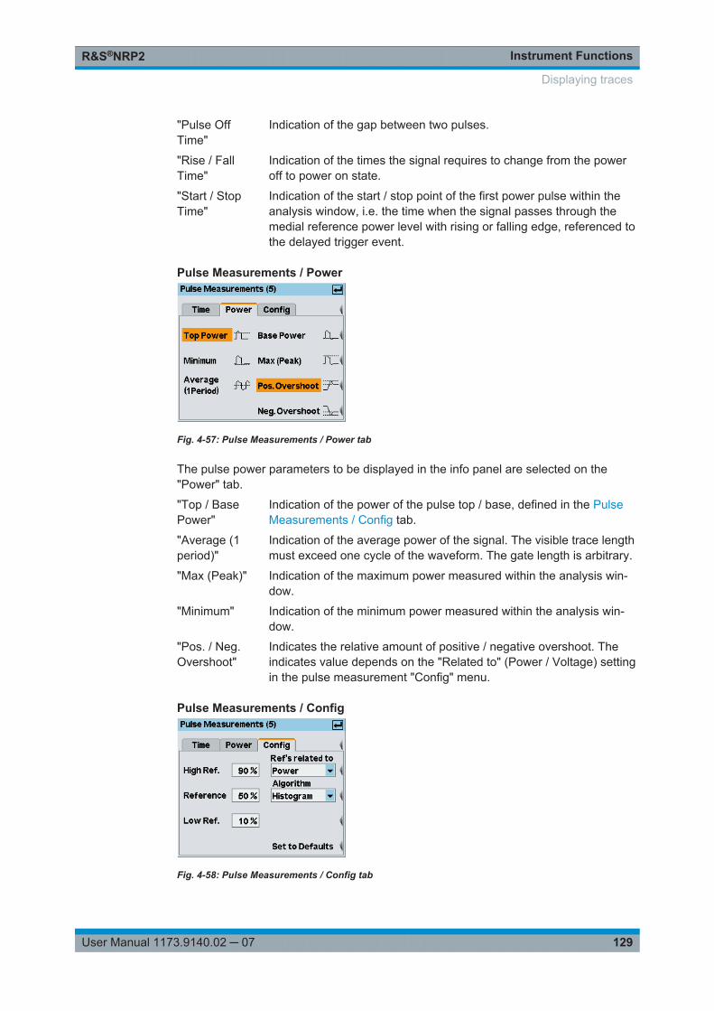
Instrument FunctionsR&S®NRP2
129User Manual 1173.9140.02 ─ 07
"Pulse OffTime"
Indication of the gap between two pulses.
"Rise / FallTime"
Indication of the times the signal requires to change from the poweroff to power on state.
"Start / StopTime"
Indication of the start / stop point of the first power pulse within theanalysis window, i.e. the time when the signal passes through themedial reference power level with rising or falling edge, referenced tothe delayed trigger event.
Pulse Measurements / Power
Fig. 4-57: Pulse Measurements / Power tab
The pulse power parameters to be displayed in the info panel are selected on the"Power" tab.
"Top / BasePower"
Indication of the power of the pulse top / base, defined in the PulseMeasurements / Config tab.
"Average (1period)"
Indication of the average power of the signal. The visible trace lengthmust exceed one cycle of the waveform. The gate length is arbitrary.
"Max (Peak)" Indication of the maximum power measured within the analysis win-dow.
"Minimum" Indication of the minimum power measured within the analysis win-dow.
"Pos. / Neg.Overshoot"
Indicates the relative amount of positive / negative overshoot. Theindicates value depends on the "Related to" (Power / Voltage) settingin the pulse measurement "Config" menu.
Pulse Measurements / Config
Fig. 4-58: Pulse Measurements / Config tab
Displaying traces
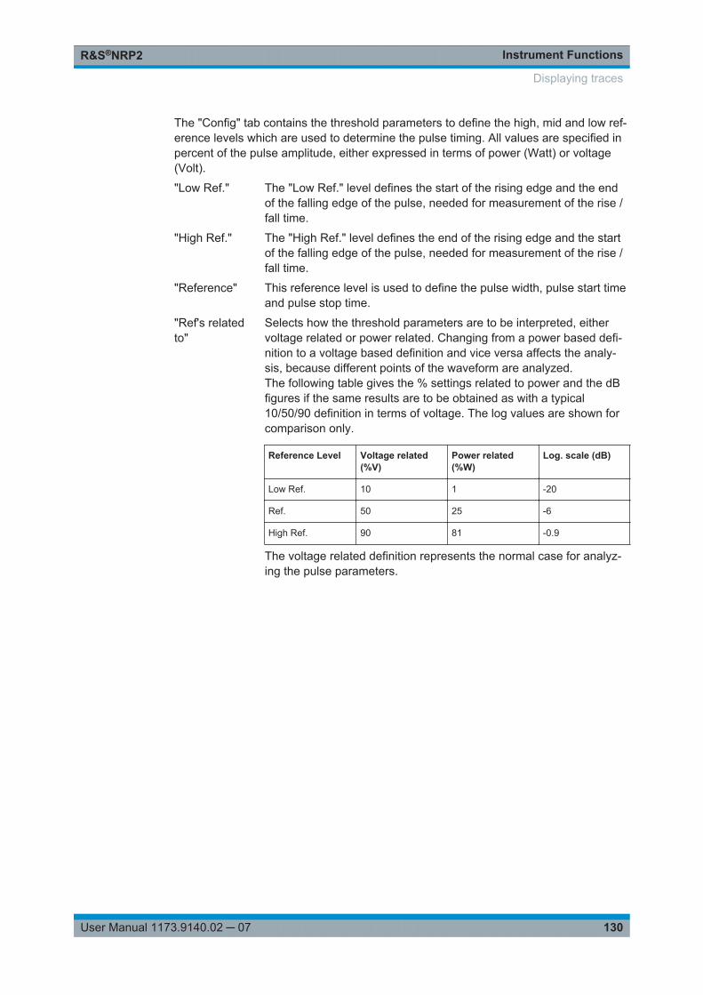
Instrument FunctionsR&S®NRP2
130User Manual 1173.9140.02 ─ 07
The "Config" tab contains the threshold parameters to define the high, mid and low ref-erence levels which are used to determine the pulse timing. All values are specified inpercent of the pulse amplitude, either expressed in terms of power (Watt) or voltage(Volt).
"Low Ref." The "Low Ref." level defines the start of the rising edge and the endof the falling edge of the pulse, needed for measurement of the rise /fall time.
"High Ref." The "High Ref." level defines the end of the rising edge and the startof the falling edge of the pulse, needed for measurement of the rise /fall time.
"Reference" This reference level is used to define the pulse width, pulse start timeand pulse stop time.
"Ref's relatedto"
Selects how the threshold parameters are to be interpreted, eithervoltage related or power related. Changing from a power based defi-nition to a voltage based definition and vice versa affects the analy-sis, because different points of the waveform are analyzed.The following table gives the % settings related to power and the dBfigures if the same results are to be obtained as with a typical10/50/90 definition in terms of voltage. The log values are shown forcomparison only.
Reference Level Voltage related(%V)
Power related(%W)
Log. scale (dB)
Low Ref. 10 1 -20
Ref. 50 25 -6
High Ref. 90 81 -0.9
The voltage related definition represents the normal case for analyz-ing the pulse parameters.
Displaying traces
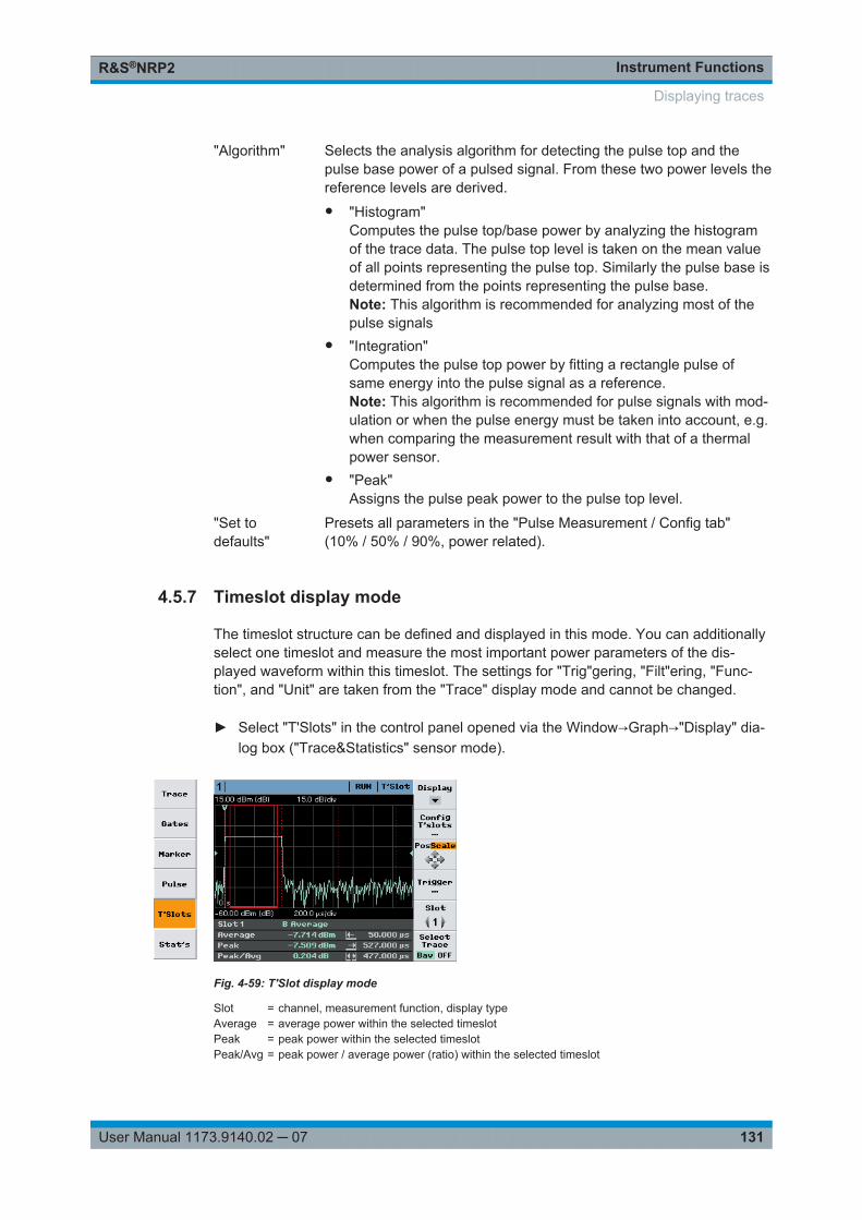
Instrument FunctionsR&S®NRP2
131User Manual 1173.9140.02 ─ 07
"Algorithm" Selects the analysis algorithm for detecting the pulse top and thepulse base power of a pulsed signal. From these two power levels thereference levels are derived.● "Histogram"
Computes the pulse top/base power by analyzing the histogramof the trace data. The pulse top level is taken on the mean valueof all points representing the pulse top. Similarly the pulse base isdetermined from the points representing the pulse base.Note: This algorithm is recommended for analyzing most of thepulse signals
● "Integration"Computes the pulse top power by fitting a rectangle pulse ofsame energy into the pulse signal as a reference.Note: This algorithm is recommended for pulse signals with mod-ulation or when the pulse energy must be taken into account, e.g.when comparing the measurement result with that of a thermalpower sensor.
● "Peak"Assigns the pulse peak power to the pulse top level.
"Set todefaults"
Presets all parameters in the "Pulse Measurement / Config tab"(10% / 50% / 90%, power related).
4.5.7 Timeslot display mode
The timeslot structure can be defined and displayed in this mode. You can additionallyselect one timeslot and measure the most important power parameters of the dis-played waveform within this timeslot. The settings for "Trig"gering, "Filt"ering, "Func-tion", and "Unit" are taken from the "Trace" display mode and cannot be changed.
► Select "T'Slots" in the control panel opened via the Window→Graph→"Display" dia-log box ("Trace&Statistics" sensor mode).
Fig. 4-59: T'Slot display mode
Slot = channel, measurement function, display typeAverage = average power within the selected timeslotPeak = peak power within the selected timeslotPeak/Avg = peak power / average power (ratio) within the selected timeslot
Displaying traces
Instrument FunctionsR&S®NRP2
132User Manual 1173.9140.02 ─ 07
I← = start of measurement→I = stopt of measurementI←→I = duration of measurement
Time slots are marked by dotted lines. The period of the currently selected time slotover which the signal is averaged is marked by a colored frame with a continuouslines. If exclude times have been set this period is shorter than the nominal time slotwidth.
The defined time slot structure is common for all diplayed waveforms. Individual timeslot structures for specific channels (sensors) can only be configured in numeric "T'slo-tAV" mode.
Tips for power measurement in timeslots● Load mobile radio standard (chapter 4.6.4, "Loading settings for mobile radio
standards", on page 142) or enter the parameters of the timeslot structure in the"Config T'Slots" menu.
● Set screen so that the envelope of a complete frame is displayed.● Open "Trigger" dialog box and set "Delay" so that the timeslot structure coincides
with the measured envelope.● To increase the measurement accuracy,
– expand the window horizontally to such an extent that the selected timeslot isdisplayed in adequate size
– perform measurement in the numeric "Timeslot Av" mode.This mode operates with precisely the time resolution available from the sensor(sample period). In the graphic mode the time resolution is determined by thewidth of a point (pixel).
SCPI commands:
Select sensor function:
[SENSe<[1]..4>]:FUNCtion[:ON] on page 269
Define calculation of measurement result:
CALCulate<[1]..8>:FEED<[1]|2> on page 226
Read result:
FETCh? on page 211
4.5.7.1 Measurement results
The measured values for the selected time slot and trace (waveform) are indicated inthe info panel below the graph.
Displaying traces
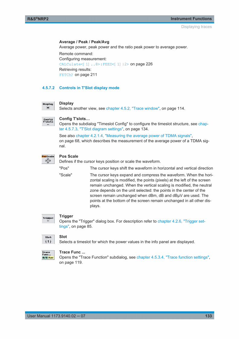
Instrument FunctionsR&S®NRP2
133User Manual 1173.9140.02 ─ 07
Average / Peak / Peak/AvgAverage power, peak power and the ratio peak power to average power.
Remote command: Configuring measurement:CALCulate<[1]..8>:FEED<[1]|2> on page 226Retrieving results:FETCh? on page 211
4.5.7.2 Controls in T'Slot display mode
DisplaySelects another view, see chapter 4.5.2, "Trace window", on page 114.
Config T'slots…Opens the subdialog "Timeslot Config" to configure the timeslot structure, see chap-ter 4.5.7.3, "T'Slot diagram settings", on page 134.
See also chapter 4.2.1.4, "Measuring the average power of TDMA signals",on page 68, which describes the measurement of the average power of a TDMA sig-nal.
Pos ScaleDefines if the cursor keys position or scale the waveform.
"Pos" The cursor keys shift the waveform in horizontal and vertical direction
"Scale" The cursor keys expand and compress the waveform. When the hori-zontal scaling is modified, the points (pixels) at the left of the screenremain unchanged. When the vertical scaling is modified, the neutralzone depends on the unit selected: the points in the center of thescreen remain unchanged when dBm, dB and dBµV are used. Thepoints at the bottom of the screen remain unchanged in all other dis-plays.
TriggerOpens the "Trigger" dialog box. For description refer to chapter 4.2.6, "Trigger set-tings", on page 85.
SlotSelects a timeslot for which the power values in the info panel are displayed.
Trace Func ...Opens the "Trace Function" subdialog, see chapter 4.5.3.4, "Trace function settings",on page 119.
Displaying traces
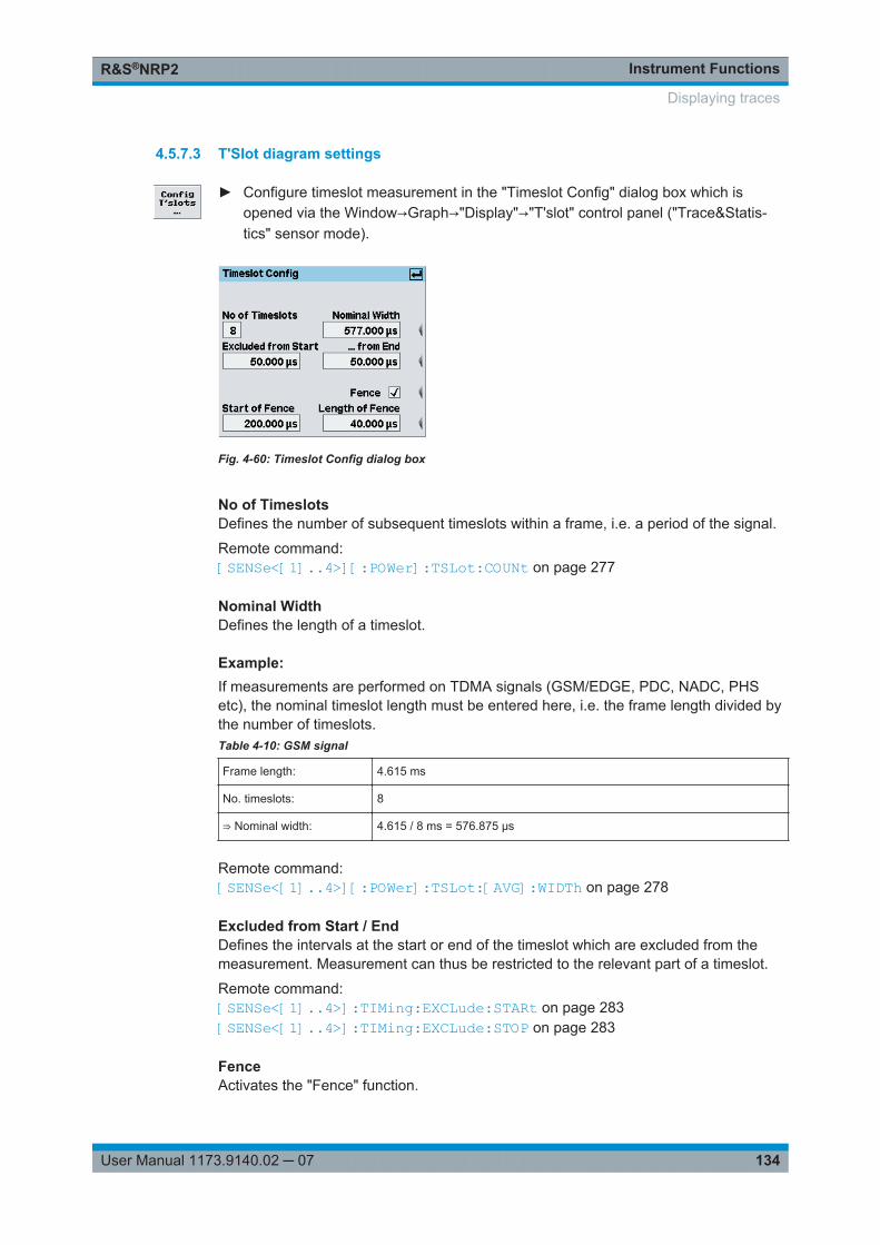
Instrument FunctionsR&S®NRP2
134User Manual 1173.9140.02 ─ 07
4.5.7.3 T'Slot diagram settings
► Configure timeslot measurement in the "Timeslot Config" dialog box which isopened via the Window→Graph→"Display"→"T'slot" control panel ("Trace&Statis-tics" sensor mode).
Fig. 4-60: Timeslot Config dialog box
No of TimeslotsDefines the number of subsequent timeslots within a frame, i.e. a period of the signal.
Remote command: [SENSe<[1]..4>][:POWer]:TSLot:COUNt on page 277
Nominal WidthDefines the length of a timeslot.
Example: If measurements are performed on TDMA signals (GSM/EDGE, PDC, NADC, PHSetc), the nominal timeslot length must be entered here, i.e. the frame length divided bythe number of timeslots.Table 4-10: GSM signal
Frame length: 4.615 ms
No. timeslots: 8
⇒ Nominal width: 4.615 / 8 ms = 576.875 μs
Remote command: [SENSe<[1]..4>][:POWer]:TSLot:[AVG]:WIDTh on page 278
Excluded from Start / EndDefines the intervals at the start or end of the timeslot which are excluded from themeasurement. Measurement can thus be restricted to the relevant part of a timeslot.
Remote command: [SENSe<[1]..4>]:TIMing:EXCLude:STARt on page 283[SENSe<[1]..4>]:TIMing:EXCLude:STOP on page 283
FenceActivates the "Fence" function.
Displaying traces
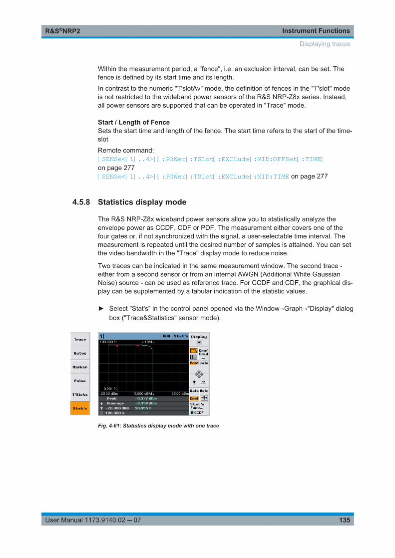
Instrument FunctionsR&S®NRP2
135User Manual 1173.9140.02 ─ 07
Within the measurement period, a "fence", i.e. an exclusion interval, can be set. Thefence is defined by its start time and its length.
In contrast to the numeric "T'slotAv" mode, the definition of fences in the "T'slot" modeis not restricted to the wideband power sensors of the R&S NRP-Z8x series. Instead,all power sensors are supported that can be operated in "Trace" mode.
Start / Length of FenceSets the start time and length of the fence. The start time refers to the start of the time-slot
Remote command: [SENSe<[1]..4>][:POWer]:TSLot[:EXCLude]:MID:OFFSet[:TIME]on page 277[SENSe<[1]..4>][:POWer]:TSLot[:EXCLude]:MID:TIME on page 277
4.5.8 Statistics display mode
The R&S NRP-Z8x wideband power sensors allow you to statistically analyze theenvelope power as CCDF, CDF or PDF. The measurement either covers one of thefour gates or, if not synchronized with the signal, a user-selectable time interval. Themeasurement is repeated until the desired number of samples is attained. You can setthe video bandwidth in the "Trace" display mode to reduce noise.
Two traces can be indicated in the same measurement window. The second trace -either from a second sensor or from an internal AWGN (Additional White GaussianNoise) source - can be used as reference trace. For CCDF and CDF, the graphical dis-play can be supplemented by a tabular indication of the statistic values.
► Select "Stat's" in the control panel opened via the Window→Graph→"Display" dialogbox ("Trace&Statistics" sensor mode).
Fig. 4-61: Statistics display mode with one trace
Displaying traces
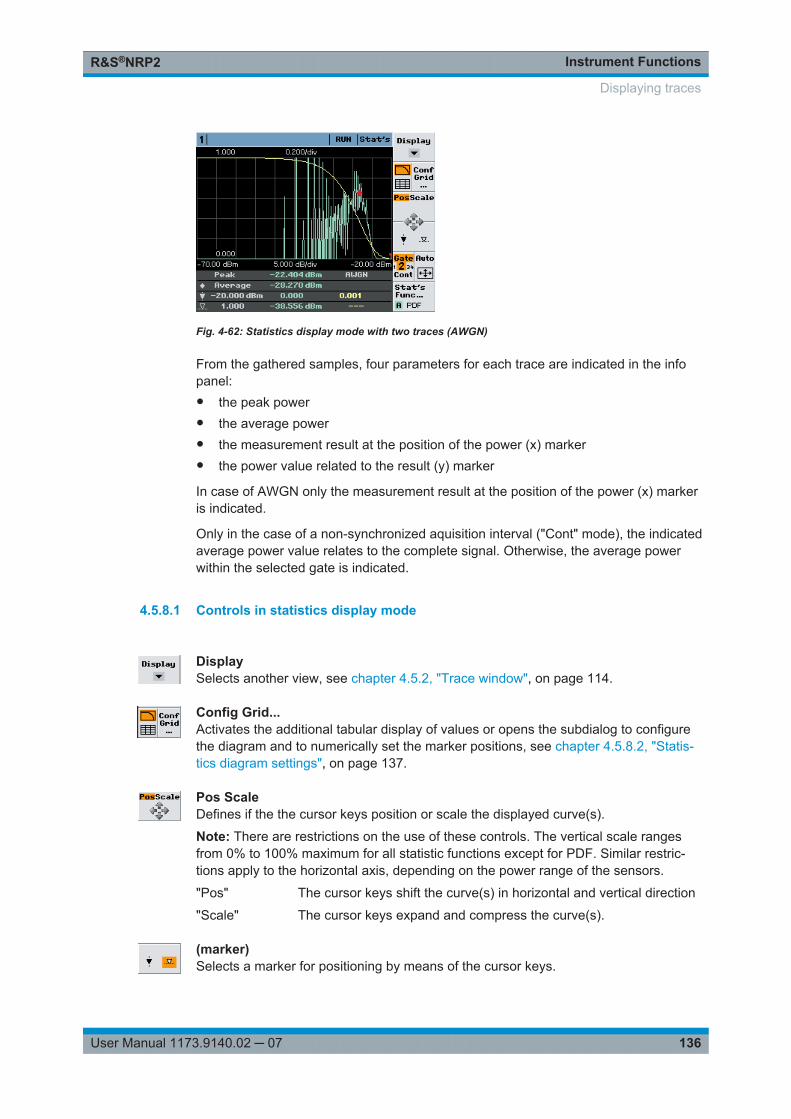
Instrument FunctionsR&S®NRP2
136User Manual 1173.9140.02 ─ 07
Fig. 4-62: Statistics display mode with two traces (AWGN)
From the gathered samples, four parameters for each trace are indicated in the infopanel:● the peak power● the average power● the measurement result at the position of the power (x) marker● the power value related to the result (y) marker
In case of AWGN only the measurement result at the position of the power (x) markeris indicated.
Only in the case of a non-synchronized aquisition interval ("Cont" mode), the indicatedaverage power value relates to the complete signal. Otherwise, the average powerwithin the selected gate is indicated.
4.5.8.1 Controls in statistics display mode
DisplaySelects another view, see chapter 4.5.2, "Trace window", on page 114.
Config Grid...Activates the additional tabular display of values or opens the subdialog to configurethe diagram and to numerically set the marker positions, see chapter 4.5.8.2, "Statis-tics diagram settings", on page 137.
Pos ScaleDefines if the the cursor keys position or scale the displayed curve(s).
Note: There are restrictions on the use of these controls. The vertical scale rangesfrom 0% to 100% maximum for all statistic functions except for PDF. Similar restric-tions apply to the horizontal axis, depending on the power range of the sensors.
"Pos" The cursor keys shift the curve(s) in horizontal and vertical direction
"Scale" The cursor keys expand and compress the curve(s).
(marker)Selects a marker for positioning by means of the cursor keys.
Displaying traces
Instrument FunctionsR&S®NRP2
137User Manual 1173.9140.02 ─ 07
the power (x) marker is positioned to a power value; the associatedvalue of the distribution (distribution density) function is measured.
the result (y) marker is positioned to a measured value of the distribu-tion (distribution density) function; the associated power value is indi-cated.If there are several power values that coincide with the set value ofthe distribution (distribution density) function, the result marker can bepositioned to the wanted value using the left/right cursor keys.
Gate / ContDefines the acquisition interval. Four gates and an unsynchronized time interval "Cont"can be selected. The selected acquisition interval is highlighted in the softkey display.Moreover, if a gate is selected, its number is enlarged.
"[1] [2] 3 [4]" Select one of four provided gates.
"Cont" Select the unsynchronized time interval.Note: The length of the time interval can be set in the Aperture dialogbox of the "Stat's function" dialog.
AutoScales the result and the power axis in such a way that the trace is optimally displayed.
Statistic FunctionsOpens the "Statistics Functions" subdialog for selection of a distribution function andone or two traces for display. A statistical evaluation of combined results from differentchannels, e.g. power ratios, is not supported.
4.5.8.2 Statistics diagram settings
Activate indication of additional values or open menu for configuration of the statisticsdisplay in the "Stat's Config" dialog box, including markers.
Activating tabular indication of statitical values for CDF and CCDF
► Select "Stat's Config..." in the control panel opened via the Window→Graph→"Dis-play"→"Stat's" → control panel ("Trace&Statistics" sensor mode).
Displaying traces
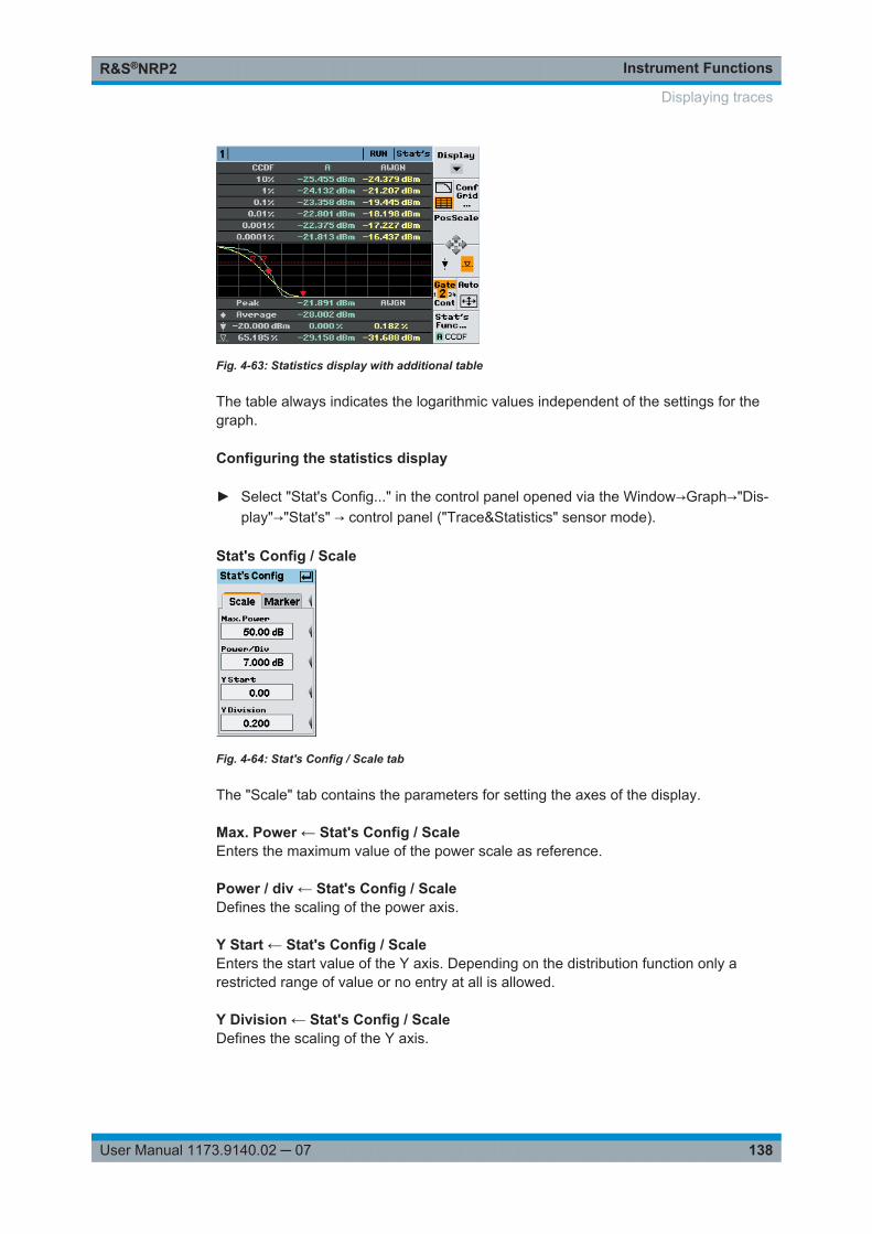
Instrument FunctionsR&S®NRP2
138User Manual 1173.9140.02 ─ 07
Fig. 4-63: Statistics display with additional table
The table always indicates the logarithmic values independent of the settings for thegraph.
Configuring the statistics display
► Select "Stat's Config..." in the control panel opened via the Window→Graph→"Dis-play"→"Stat's" → control panel ("Trace&Statistics" sensor mode).
Stat's Config / Scale
Fig. 4-64: Stat's Config / Scale tab
The "Scale" tab contains the parameters for setting the axes of the display.
Max. Power ← Stat's Config / ScaleEnters the maximum value of the power scale as reference.
Power / div ← Stat's Config / ScaleDefines the scaling of the power axis.
Y Start ← Stat's Config / ScaleEnters the start value of the Y axis. Depending on the distribution function only arestricted range of value or no entry at all is allowed.
Y Division ← Stat's Config / ScaleDefines the scaling of the Y axis.
Displaying traces
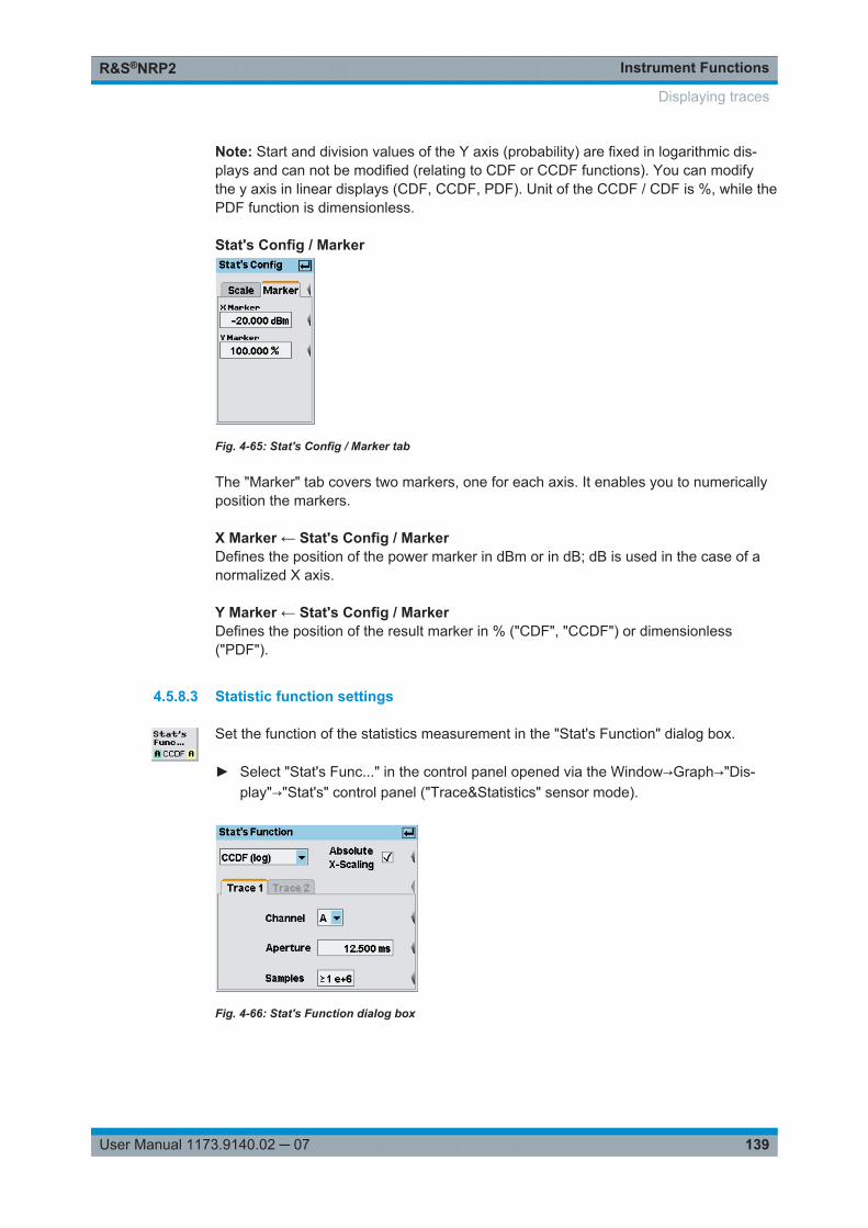
Instrument FunctionsR&S®NRP2
139User Manual 1173.9140.02 ─ 07
Note: Start and division values of the Y axis (probability) are fixed in logarithmic dis-plays and can not be modified (relating to CDF or CCDF functions). You can modifythe y axis in linear displays (CDF, CCDF, PDF). Unit of the CCDF / CDF is %, while thePDF function is dimensionless.
Stat's Config / Marker
Fig. 4-65: Stat's Config / Marker tab
The "Marker" tab covers two markers, one for each axis. It enables you to numericallyposition the markers.
X Marker ← Stat's Config / MarkerDefines the position of the power marker in dBm or in dB; dB is used in the case of anormalized X axis.
Y Marker ← Stat's Config / MarkerDefines the position of the result marker in % ("CDF", "CCDF") or dimensionless("PDF").
4.5.8.3 Statistic function settings
Set the function of the statistics measurement in the "Stat's Function" dialog box.
► Select "Stat's Func..." in the control panel opened via the Window→Graph→"Dis-play"→"Stat's" control panel ("Trace&Statistics" sensor mode).
Fig. 4-66: Stat's Function dialog box
Displaying traces
Instrument FunctionsR&S®NRP2
140User Manual 1173.9140.02 ─ 07
Statistics evaluation functionNote: A linear (lin) or logarithmic (log) scale is available for "CCDF" and "CDF". The"PDF" can only be displayed linearly.
"CCDF" Complementary Cumulative Distribution Function. Displays the prob-ability of the envelope power being higher than the corresponding Xaxis power value.
"CDF" Cumulative Distribution Function.Displays the probability of the envelope power being lower than thecorresponding X axis power value.
"PDF" Probability Density Function.Displays a normalized distribution density of the envelope power. Themeasurement result is dimensionless and – in contrast to a non-nor-malized "PDF" – is independent of the magnitude of the averagepower value (Av). Integrating the normalized "PDF" over power pro-vides the average power value (Av).
Remote command: [SENSe<[1]..4>]:FUNCtion[:ON] on page 269
Absolute X-ScalingScales the X axis in terms of absolute power (dBm) if activated
Normalizes the X axis with respect to average power (dB) if deactivated.
Trace 1 / 2Selects tab "Trace 1" or "Trace 2" to configure the statistic measurement for the 1st or2nd trace.
An internal AWGN source is available for the second trace, thus providing a standardsignal reference.
ChannelSelects the channel for the respective trace. A statistical evaluation of combinedresults from different channels, e.g. power ratios, is not supported.
ApertureSets the length of the aquisition interval with unsynchronized acquisition ("Cont", see"Gate / Cont" on page 137).
In addition to, and independent of, the setting of the aperture time for the measurementof an average power value (Av) (chapter 4.2.1.2, "Continuous average-power mea-surements", on page 66 ), you can use this parameter to set the length of theunsynchronized time interval for the statistical analysis of the signal.
Remote command: [SENSe<[1]..4>]:STATistics:TIME on page 283
SamplesEnters the required minimum number of samples.
Displaying traces
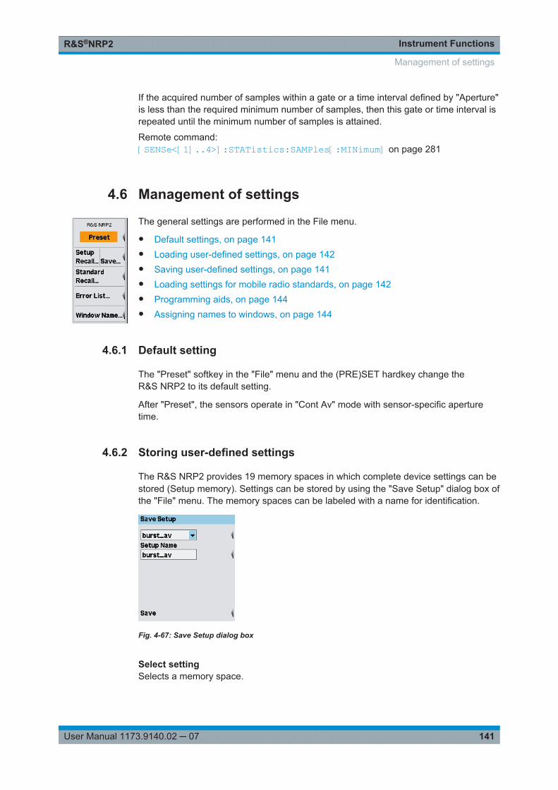
Instrument FunctionsR&S®NRP2
141User Manual 1173.9140.02 ─ 07
If the acquired number of samples within a gate or a time interval defined by "Aperture"is less than the required minimum number of samples, then this gate or time interval isrepeated until the minimum number of samples is attained.
Remote command: [SENSe<[1]..4>]:STATistics:SAMPles[:MINimum] on page 281
4.6 Management of settings
The general settings are performed in the File menu.
● Default settings, on page 141● Loading user-defined settings, on page 142● Saving user-defined settings, on page 141● Loading settings for mobile radio standards, on page 142● Programming aids, on page 144● Assigning names to windows, on page 144
4.6.1 Default setting
The "Preset" softkey in the "File" menu and the (PRE)SET hardkey change theR&S NRP2 to its default setting.
After "Preset", the sensors operate in "Cont Av" mode with sensor-specific aperturetime.
4.6.2 Storing user-defined settings
The R&S NRP2 provides 19 memory spaces in which complete device settings can bestored (Setup memory). Settings can be stored by using the "Save Setup" dialog box ofthe "File" menu. The memory spaces can be labeled with a name for identification.
Fig. 4-67: Save Setup dialog box
Select settingSelects a memory space.
Management of settings
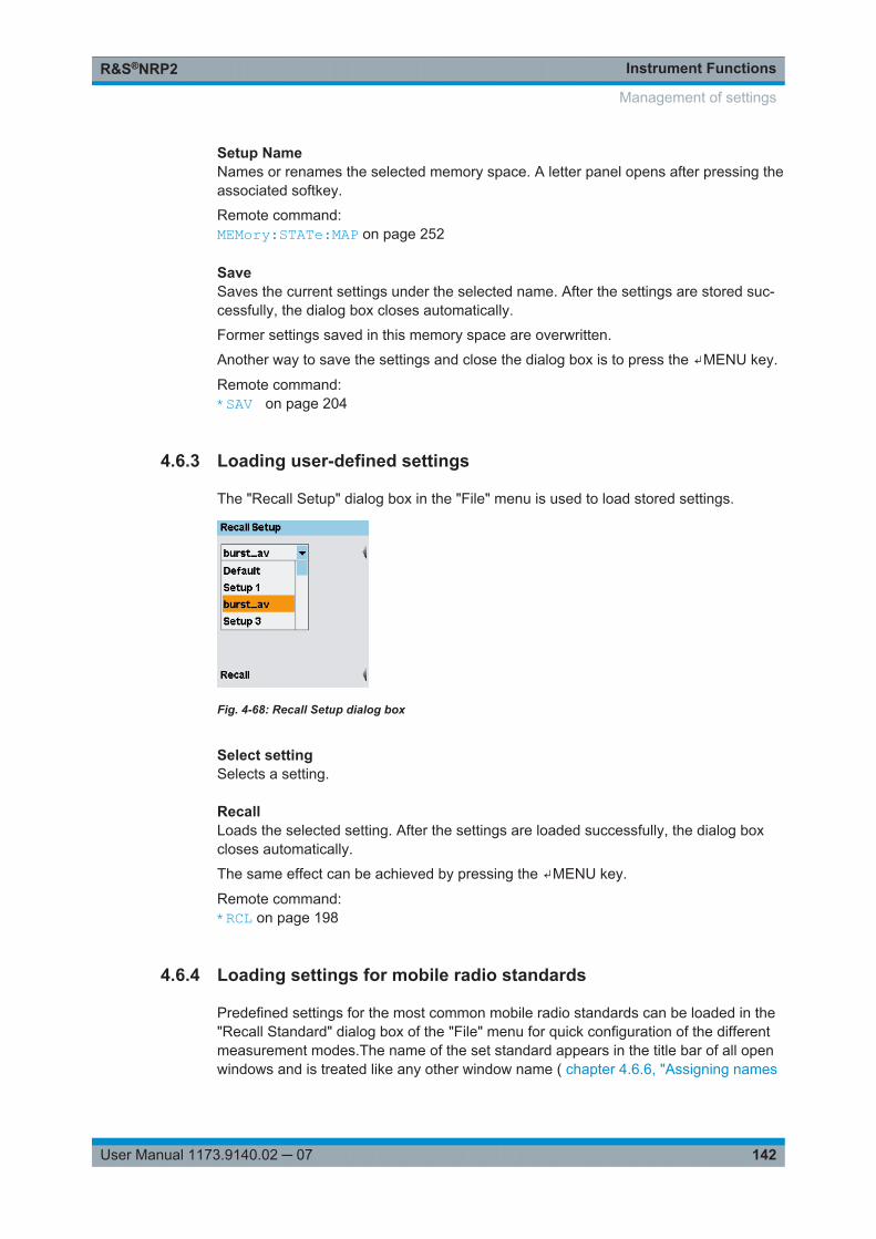
Instrument FunctionsR&S®NRP2
142User Manual 1173.9140.02 ─ 07
Setup NameNames or renames the selected memory space. A letter panel opens after pressing theassociated softkey.
Remote command: MEMory:STATe:MAP on page 252
SaveSaves the current settings under the selected name. After the settings are stored suc-cessfully, the dialog box closes automatically.
Former settings saved in this memory space are overwritten.
Another way to save the settings and close the dialog box is to press the ↵MENU key.
Remote command: *SAV on page 204
4.6.3 Loading user-defined settings
The "Recall Setup" dialog box in the "File" menu is used to load stored settings.
Fig. 4-68: Recall Setup dialog box
Select settingSelects a setting.
RecallLoads the selected setting. After the settings are loaded successfully, the dialog boxcloses automatically.
The same effect can be achieved by pressing the ↵MENU key.
Remote command: *RCL on page 198
4.6.4 Loading settings for mobile radio standards
Predefined settings for the most common mobile radio standards can be loaded in the"Recall Standard" dialog box of the "File" menu for quick configuration of the differentmeasurement modes.The name of the set standard appears in the title bar of all openwindows and is treated like any other window name ( chapter 4.6.6, "Assigning names
Management of settings
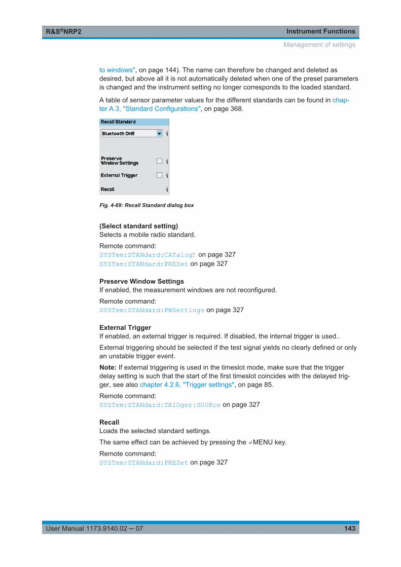
Instrument FunctionsR&S®NRP2
143User Manual 1173.9140.02 ─ 07
to windows", on page 144). The name can therefore be changed and deleted asdesired, but above all it is not automatically deleted when one of the preset parametersis changed and the instrument setting no longer corresponds to the loaded standard.
A table of sensor parameter values for the different standards can be found in chap-ter A.3, "Standard Configurations", on page 368.
Fig. 4-69: Recall Standard dialog box
(Select standard setting)Selects a mobile radio standard.
Remote command: SYSTem:STANdard:CATalog? on page 327SYSTem:STANdard:PRESet on page 327
Preserve Window SettingsIf enabled, the measurement windows are not reconfigured.
Remote command: SYSTem:STANdard:PWSettings on page 327
External TriggerIf enabled, an external trigger is required. If disabled, the internal trigger is used..
External triggering should be selected if the test signal yields no clearly defined or onlyan unstable trigger event.
Note: If external triggering is used in the timeslot mode, make sure that the triggerdelay setting is such that the start of the first timeslot coincides with the delayed trig-ger, see also chapter 4.2.6, "Trigger settings", on page 85.
Remote command: SYSTem:STANdard:TRIGger:SOURce on page 327
RecallLoads the selected standard settings.
The same effect can be achieved by pressing the ↵MENU key.
Remote command: SYSTem:STANdard:PRESet on page 327
Management of settings
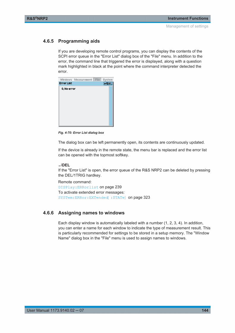
Instrument FunctionsR&S®NRP2
144User Manual 1173.9140.02 ─ 07
4.6.5 Programming aids
If you are developing remote control programs, you can display the contents of theSCPI error queue in the "Error List" dialog box of the "File" menu. In addition to theerror, the command line that triggered the error is displayed, along with a questionmark highlighted in black at the point where the command interpreter detected theerror.
Fig. 4-70: Error List dialog box
The dialog box can be left permanently open, its contents are continuously updated.
If the device is already in the remote state, the menu bar is replaced and the error listcan be opened with the topmost softkey.
↵DELIf the "Error List" is open, the error queue of the R&S NRP2 can be deleted by pressingthe DEL/1TRIG hardkey.
Remote command: DISPlay:ERRorlist on page 239To activate extended error messages:SYSTem:ERRor:EXTended[:STATe] on page 323
4.6.6 Assigning names to windows
Each display window is automatically labeled with a number (1, 2, 3, 4). In addition,you can enter a name for each window to indicate the type of measurement result. Thisis particularly recommended for settings to be stored in a setup memory. The "WindowName" dialog box in the "File" menu is used to assign names to windows.
Management of settings
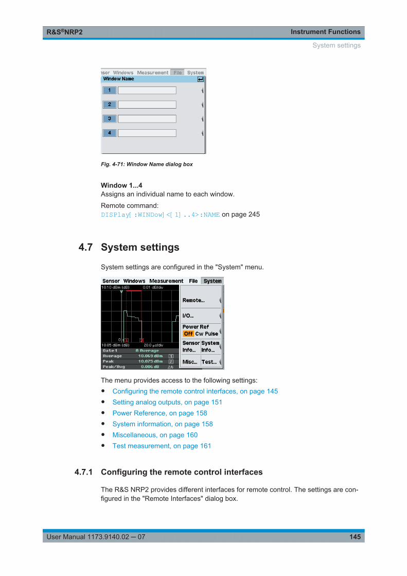
Instrument FunctionsR&S®NRP2
145User Manual 1173.9140.02 ─ 07
Fig. 4-71: Window Name dialog box
Window 1...4Assigns an individual name to each window.
Remote command: DISPlay[:WINDow]<[1]..4>:NAME on page 245
4.7 System settings
System settings are configured in the "System" menu.
The menu provides access to the following settings:● Configuring the remote control interfaces, on page 145● Setting analog outputs, on page 151● Power Reference, on page 158● System information, on page 158● Miscellaneous, on page 160● Test measurement, on page 161
4.7.1 Configuring the remote control interfaces
The R&S NRP2 provides different interfaces for remote control. The settings are con-figured in the "Remote Interfaces" dialog box.
System settings
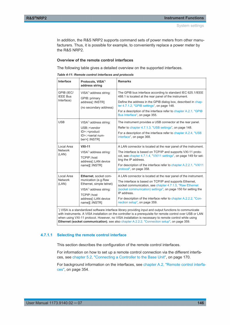
Instrument FunctionsR&S®NRP2
146User Manual 1173.9140.02 ─ 07
In addition, the R&S NRP2 supports command sets of power meters from other manu-facturers. Thus, it is possible for example, to conveniently replace a power meter bythe R&S NRP2.
Overview of the remote control interfaces
The following table gives a detailed overview on the supported interfaces.
Table 4-11: Remote control interfaces and protocols
Interface Protocols, VISA*)
address stringRemarks
GPIB (IEC/IEEE BusInterface)
VISA*) address string:
GPIB::primaryaddress[::INSTR]
(no secondary address)
The GPIB bus interface according to standard IEC 625.1/IEEE488.1 is located at the rear panel of the instrument.
Define the address in the GPIB dialog box, described in chap-ter 4.7.1.2, "GPIB settings", on page 148.
For a description of the interface refer to chapter A.2.1, "GPIBBus Interface", on page 355.
USB VISA*) address string:
USB::<vendorID>::<productID>::<serial num-ber>[::INSTR]
The instrument provides a USB connector at the rear panel.
Refer to chapter 4.7.1.3, "USB settings", on page 148.
For a description of the interface refer to chapter A.2.4, "USBinterface", on page 368.
Local AreaNetwork(LAN)
VXI-11
VISA*) address string:
TCPIP::hostaddress[::LAN devicename][::INSTR]
A LAN connector is located at the rear panel of the instrument.
The interface is based on TCP/IP and supports VXI-11 proto-col, see chapter 4.7.1.4, "VXI11 settings", on page 149 for set-ting the IP address.
For description of the interface refer to chapter A.2.2.1, "VXI11protocol", on page 358.
Local AreaNetwork(LAN)
Ethernet, socket com-munication (e.g.RawEthernet, simple telnet)
VISA*) address string:
TCPIP::hostaddress[::LAN devicename][::INSTR]
A LAN connector is located at the rear panel of the instrument.
The interface is based on TCP/IP and supports Ethernet,socket communication, see chapter 4.7.1.5, "Raw Ethernet(socket communication) settings", on page 150 for setting theIP address.
For description of the interface refer to chapter A.2.2.2, "Con-nection setup", on page 359.
*) VISA is a standardized software interface library providing input and output functions to communicatewith instruments. A VISA installation on the controller is a prerequisite for remote control over USB or LANwhen using VXI-11 protocol. However, no VISA installation is necessary to remote control while usingEthernet (socket communication), see also chapter A.2.2.2, "Connection setup", on page 359.
4.7.1.1 Selecting the remote control interface
This section describes the configuration of the remote control interfaces.
For information on how to set up a remote control connection via the different interfa-ces, see chapter 5.2, "Connecting a Controller to the Base Unit", on page 170.
For background information on the interfaces, see chapter A.2, "Remote control interfa-ces", on page 354.
System settings
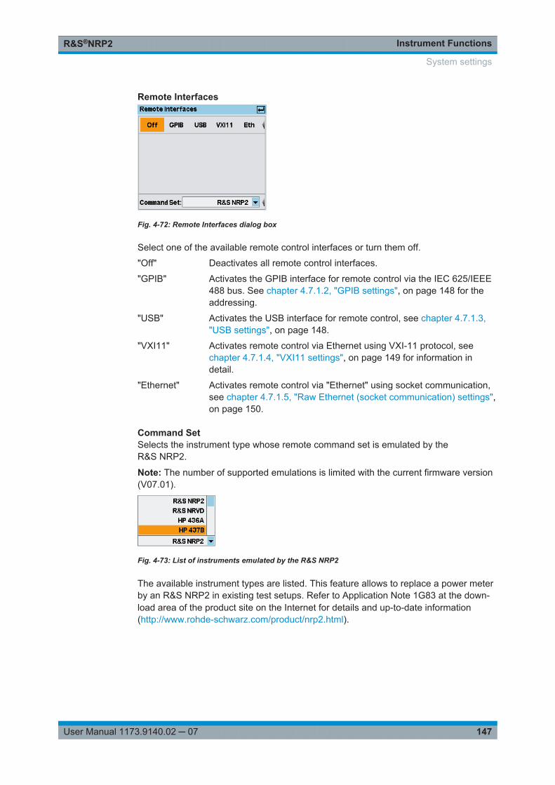
Instrument FunctionsR&S®NRP2
147User Manual 1173.9140.02 ─ 07
Remote Interfaces
Fig. 4-72: Remote Interfaces dialog box
Select one of the available remote control interfaces or turn them off.
"Off" Deactivates all remote control interfaces.
"GPIB" Activates the GPIB interface for remote control via the IEC 625/IEEE488 bus. See chapter 4.7.1.2, "GPIB settings", on page 148 for theaddressing.
"USB" Activates the USB interface for remote control, see chapter 4.7.1.3,"USB settings", on page 148.
"VXI11" Activates remote control via Ethernet using VXI-11 protocol, seechapter 4.7.1.4, "VXI11 settings", on page 149 for information indetail.
"Ethernet" Activates remote control via "Ethernet" using socket communication,see chapter 4.7.1.5, "Raw Ethernet (socket communication) settings",on page 150.
Command SetSelects the instrument type whose remote command set is emulated by theR&S NRP2.
Note: The number of supported emulations is limited with the current firmware version(V07.01).
Fig. 4-73: List of instruments emulated by the R&S NRP2
The available instrument types are listed. This feature allows to replace a power meterby an R&S NRP2 in existing test setups. Refer to Application Note 1G83 at the down-load area of the product site on the Internet for details and up-to-date information(http://www.rohde-schwarz.com/product/nrp2.html).
System settings
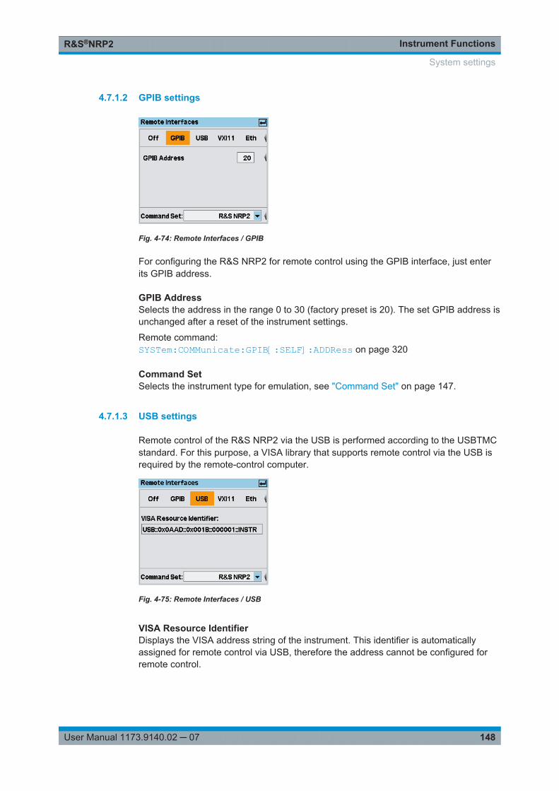
Instrument FunctionsR&S®NRP2
148User Manual 1173.9140.02 ─ 07
4.7.1.2 GPIB settings
Fig. 4-74: Remote Interfaces / GPIB
For configuring the R&S NRP2 for remote control using the GPIB interface, just enterits GPIB address.
GPIB AddressSelects the address in the range 0 to 30 (factory preset is 20). The set GPIB address isunchanged after a reset of the instrument settings.
Remote command: SYSTem:COMMunicate:GPIB[:SELF]:ADDRess on page 320
Command SetSelects the instrument type for emulation, see "Command Set" on page 147.
4.7.1.3 USB settings
Remote control of the R&S NRP2 via the USB is performed according to the USBTMCstandard. For this purpose, a VISA library that supports remote control via the USB isrequired by the remote-control computer.
Fig. 4-75: Remote Interfaces / USB
VISA Resource IdentifierDisplays the VISA address string of the instrument. This identifier is automaticallyassigned for remote control via USB, therefore the address cannot be configured forremote control.
System settings
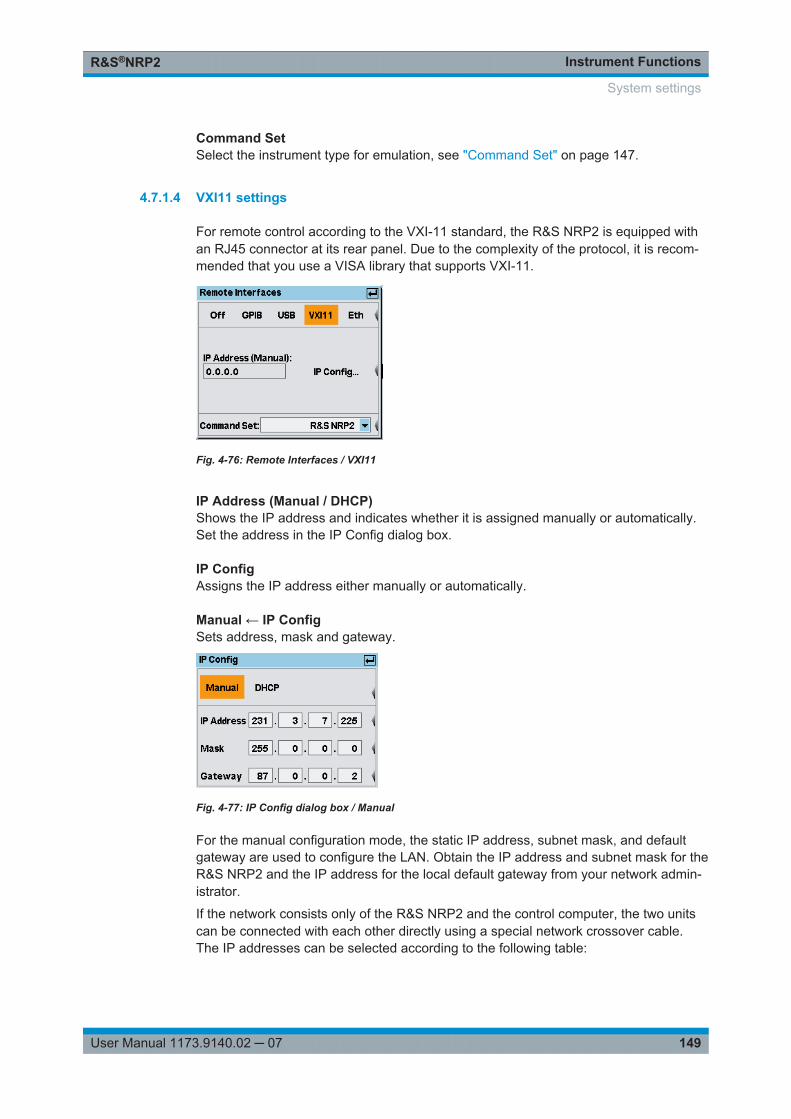
Instrument FunctionsR&S®NRP2
149User Manual 1173.9140.02 ─ 07
Command SetSelect the instrument type for emulation, see "Command Set" on page 147.
4.7.1.4 VXI11 settings
For remote control according to the VXI-11 standard, the R&S NRP2 is equipped withan RJ45 connector at its rear panel. Due to the complexity of the protocol, it is recom-mended that you use a VISA library that supports VXI-11.
Fig. 4-76: Remote Interfaces / VXI11
IP Address (Manual / DHCP)Shows the IP address and indicates whether it is assigned manually or automatically.Set the address in the IP Config dialog box.
IP ConfigAssigns the IP address either manually or automatically.
Manual ← IP ConfigSets address, mask and gateway.
Fig. 4-77: IP Config dialog box / Manual
For the manual configuration mode, the static IP address, subnet mask, and defaultgateway are used to configure the LAN. Obtain the IP address and subnet mask for theR&S NRP2 and the IP address for the local default gateway from your network admin-istrator.
If the network consists only of the R&S NRP2 and the control computer, the two unitscan be connected with each other directly using a special network crossover cable.The IP addresses can be selected according to the following table:
System settings
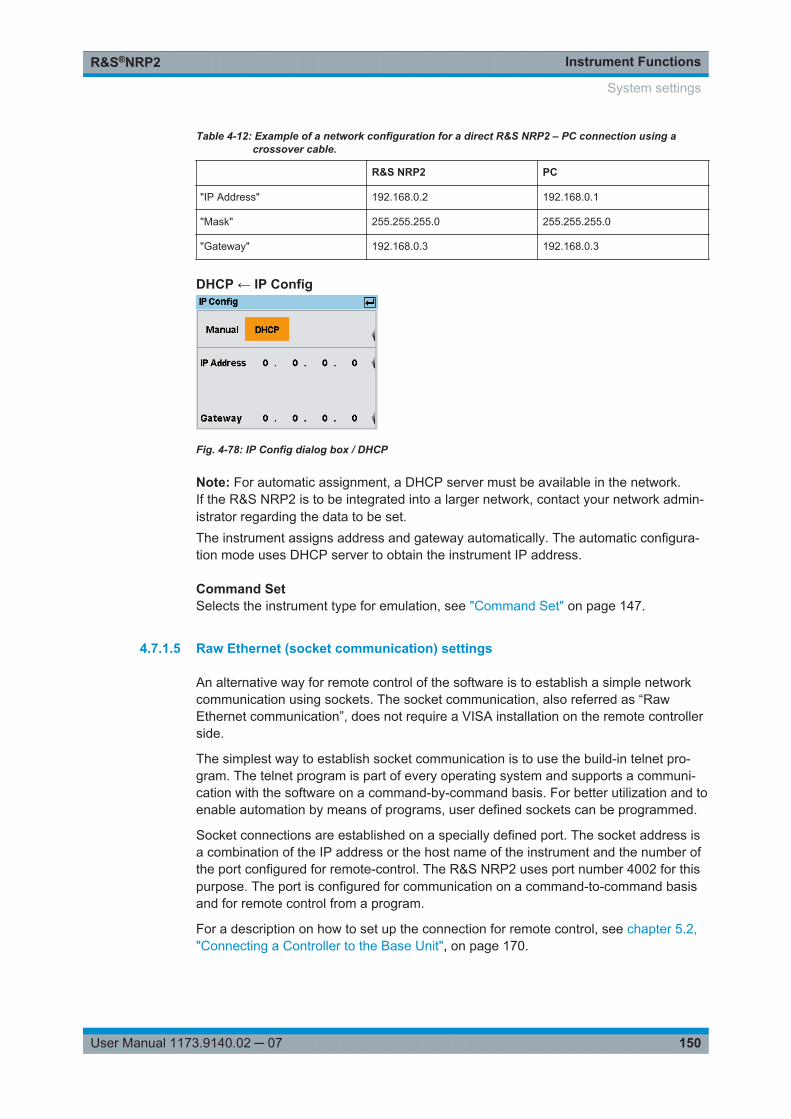
Instrument FunctionsR&S®NRP2
150User Manual 1173.9140.02 ─ 07
Table 4-12: Example of a network configuration for a direct R&S NRP2 – PC connection using acrossover cable.
R&S NRP2 PC
"IP Address" 192.168.0.2 192.168.0.1
"Mask" 255.255.255.0 255.255.255.0
"Gateway" 192.168.0.3 192.168.0.3
DHCP ← IP Config
Fig. 4-78: IP Config dialog box / DHCP
Note: For automatic assignment, a DHCP server must be available in the network.If the R&S NRP2 is to be integrated into a larger network, contact your network admin-istrator regarding the data to be set.The instrument assigns address and gateway automatically. The automatic configura-tion mode uses DHCP server to obtain the instrument IP address.
Command SetSelects the instrument type for emulation, see "Command Set" on page 147.
4.7.1.5 Raw Ethernet (socket communication) settings
An alternative way for remote control of the software is to establish a simple networkcommunication using sockets. The socket communication, also referred as “RawEthernet communication”, does not require a VISA installation on the remote controllerside.
The simplest way to establish socket communication is to use the build-in telnet pro-gram. The telnet program is part of every operating system and supports a communi-cation with the software on a command-by-command basis. For better utilization and toenable automation by means of programs, user defined sockets can be programmed.
Socket connections are established on a specially defined port. The socket address isa combination of the IP address or the host name of the instrument and the number ofthe port configured for remote-control. The R&S NRP2 uses port number 4002 for thispurpose. The port is configured for communication on a command-to-command basisand for remote control from a program.
For a description on how to set up the connection for remote control, see chapter 5.2,"Connecting a Controller to the Base Unit", on page 170.
System settings
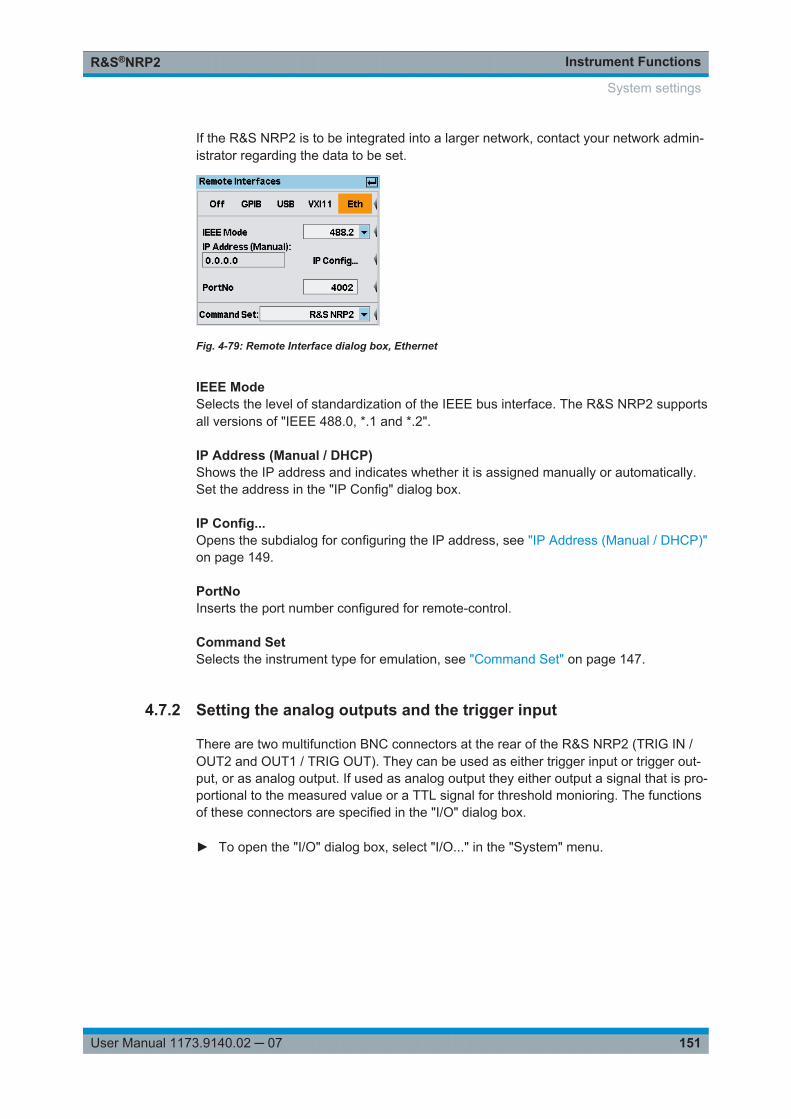
Instrument FunctionsR&S®NRP2
151User Manual 1173.9140.02 ─ 07
If the R&S NRP2 is to be integrated into a larger network, contact your network admin-istrator regarding the data to be set.
Fig. 4-79: Remote Interface dialog box, Ethernet
IEEE ModeSelects the level of standardization of the IEEE bus interface. The R&S NRP2 supportsall versions of "IEEE 488.0, *.1 and *.2".
IP Address (Manual / DHCP)Shows the IP address and indicates whether it is assigned manually or automatically.Set the address in the "IP Config" dialog box.
IP Config...Opens the subdialog for configuring the IP address, see "IP Address (Manual / DHCP)"on page 149.
PortNoInserts the port number configured for remote-control.
Command SetSelects the instrument type for emulation, see "Command Set" on page 147.
4.7.2 Setting the analog outputs and the trigger input
There are two multifunction BNC connectors at the rear of the R&S NRP2 (TRIG IN /OUT2 and OUT1 / TRIG OUT). They can be used as either trigger input or trigger out-put, or as analog output. If used as analog output they either output a signal that is pro-portional to the measured value or a TTL signal for threshold monioring. The functionsof these connectors are specified in the "I/O" dialog box.
► To open the "I/O" dialog box, select "I/O..." in the "System" menu.
System settings
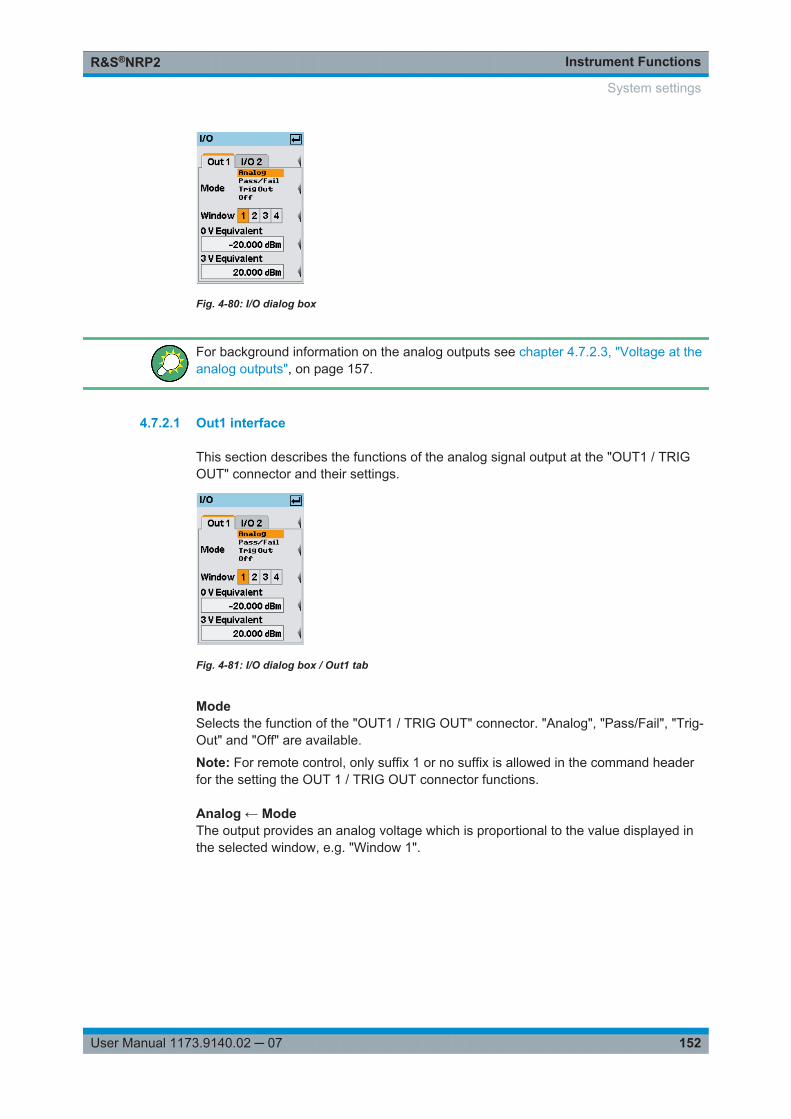
Instrument FunctionsR&S®NRP2
152User Manual 1173.9140.02 ─ 07
Fig. 4-80: I/O dialog box
For background information on the analog outputs see chapter 4.7.2.3, "Voltage at theanalog outputs", on page 157.
4.7.2.1 Out1 interface
This section describes the functions of the analog signal output at the "OUT1 / TRIGOUT" connector and their settings.
Fig. 4-81: I/O dialog box / Out1 tab
ModeSelects the function of the "OUT1 / TRIG OUT" connector. "Analog", "Pass/Fail", "Trig-Out" and "Off" are available.
Note: For remote control, only suffix 1 or no suffix is allowed in the command headerfor the setting the OUT 1 / TRIG OUT connector functions.
Analog ← ModeThe output provides an analog voltage which is proportional to the value displayed inthe selected window, e.g. "Window 1".
System settings
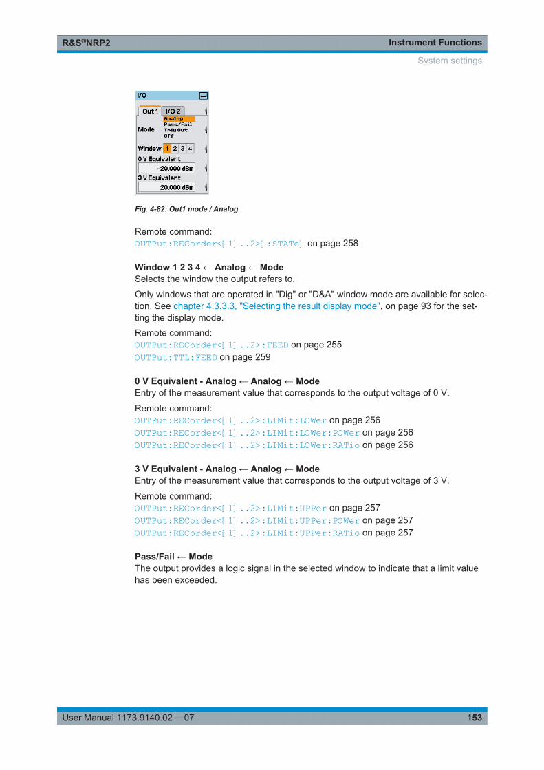
Instrument FunctionsR&S®NRP2
153User Manual 1173.9140.02 ─ 07
Fig. 4-82: Out1 mode / Analog
Remote command: OUTPut:RECorder<[1]..2>[:STATe] on page 258
Window 1 2 3 4 ← Analog ← ModeSelects the window the output refers to.
Only windows that are operated in "Dig" or "D&A" window mode are available for selec-tion. See chapter 4.3.3.3, "Selecting the result display mode", on page 93 for the set-ting the display mode.
Remote command: OUTPut:RECorder<[1]..2>:FEED on page 255OUTPut:TTL:FEED on page 259
0 V Equivalent - Analog ← Analog ← ModeEntry of the measurement value that corresponds to the output voltage of 0 V.
Remote command: OUTPut:RECorder<[1]..2>:LIMit:LOWer on page 256OUTPut:RECorder<[1]..2>:LIMit:LOWer:POWer on page 256OUTPut:RECorder<[1]..2>:LIMit:LOWer:RATio on page 256
3 V Equivalent - Analog ← Analog ← ModeEntry of the measurement value that corresponds to the output voltage of 3 V.
Remote command: OUTPut:RECorder<[1]..2>:LIMit:UPPer on page 257OUTPut:RECorder<[1]..2>:LIMit:UPPer:POWer on page 257OUTPut:RECorder<[1]..2>:LIMit:UPPer:RATio on page 257
Pass/Fail ← ModeThe output provides a logic signal in the selected window to indicate that a limit valuehas been exceeded.
System settings
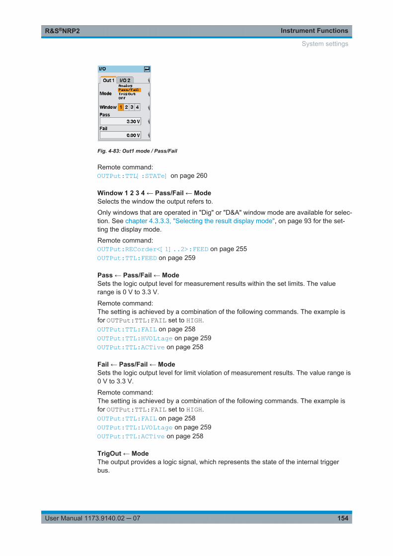
Instrument FunctionsR&S®NRP2
154User Manual 1173.9140.02 ─ 07
Fig. 4-83: Out1 mode / Pass/Fail
Remote command: OUTPut:TTL[:STATe] on page 260
Window 1 2 3 4 ← Pass/Fail ← ModeSelects the window the output refers to.
Only windows that are operated in "Dig" or "D&A" window mode are available for selec-tion. See chapter 4.3.3.3, "Selecting the result display mode", on page 93 for the set-ting the display mode.
Remote command: OUTPut:RECorder<[1]..2>:FEED on page 255OUTPut:TTL:FEED on page 259
Pass ← Pass/Fail ← ModeSets the logic output level for measurement results within the set limits. The valuerange is 0 V to 3.3 V.
Remote command: The setting is achieved by a combination of the following commands. The example isfor OUTPut:TTL:FAIL set to HIGH.OUTPut:TTL:FAIL on page 258OUTPut:TTL:HVOLtage on page 259OUTPut:TTL:ACTive on page 258
Fail ← Pass/Fail ← ModeSets the logic output level for limit violation of measurement results. The value range is0 V to 3.3 V.
Remote command: The setting is achieved by a combination of the following commands. The example isfor OUTPut:TTL:FAIL set to HIGH.OUTPut:TTL:FAIL on page 258OUTPut:TTL:LVOLtage on page 259OUTPut:TTL:ACTive on page 258
TrigOut ← ModeThe output provides a logic signal, which represents the state of the internal triggerbus.
System settings
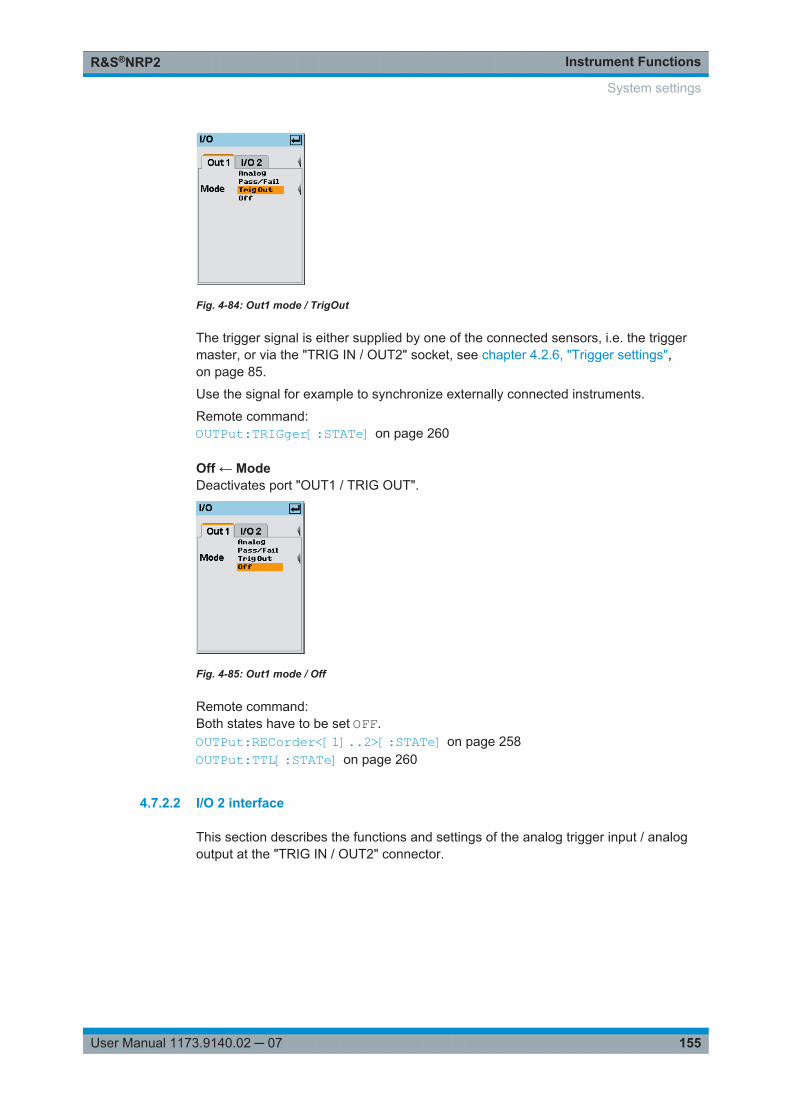
Instrument FunctionsR&S®NRP2
155User Manual 1173.9140.02 ─ 07
Fig. 4-84: Out1 mode / TrigOut
The trigger signal is either supplied by one of the connected sensors, i.e. the triggermaster, or via the "TRIG IN / OUT2" socket, see chapter 4.2.6, "Trigger settings",on page 85.
Use the signal for example to synchronize externally connected instruments.
Remote command: OUTPut:TRIGger[:STATe] on page 260
Off ← ModeDeactivates port "OUT1 / TRIG OUT".
Fig. 4-85: Out1 mode / Off
Remote command: Both states have to be set OFF.OUTPut:RECorder<[1]..2>[:STATe] on page 258OUTPut:TTL[:STATe] on page 260
4.7.2.2 I/O 2 interface
This section describes the functions and settings of the analog trigger input / analogoutput at the "TRIG IN / OUT2" connector.
System settings
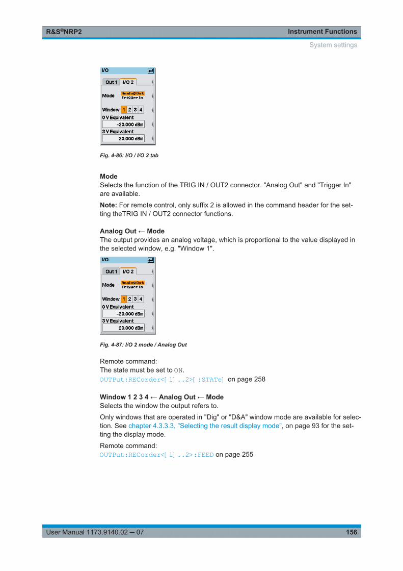
Instrument FunctionsR&S®NRP2
156User Manual 1173.9140.02 ─ 07
Fig. 4-86: I/O / I/O 2 tab
ModeSelects the function of the TRIG IN / OUT2 connector. "Analog Out" and "Trigger In"are available.
Note: For remote control, only suffix 2 is allowed in the command header for the set-ting theTRIG IN / OUT2 connector functions.
Analog Out ← ModeThe output provides an analog voltage, which is proportional to the value displayed inthe selected window, e.g. "Window 1".
Fig. 4-87: I/O 2 mode / Analog Out
Remote command: The state must be set to ON.OUTPut:RECorder<[1]..2>[:STATe] on page 258
Window 1 2 3 4 ← Analog Out ← ModeSelects the window the output refers to.
Only windows that are operated in "Dig" or "D&A" window mode are available for selec-tion. See chapter 4.3.3.3, "Selecting the result display mode", on page 93 for the set-ting the display mode.
Remote command: OUTPut:RECorder<[1]..2>:FEED on page 255
System settings
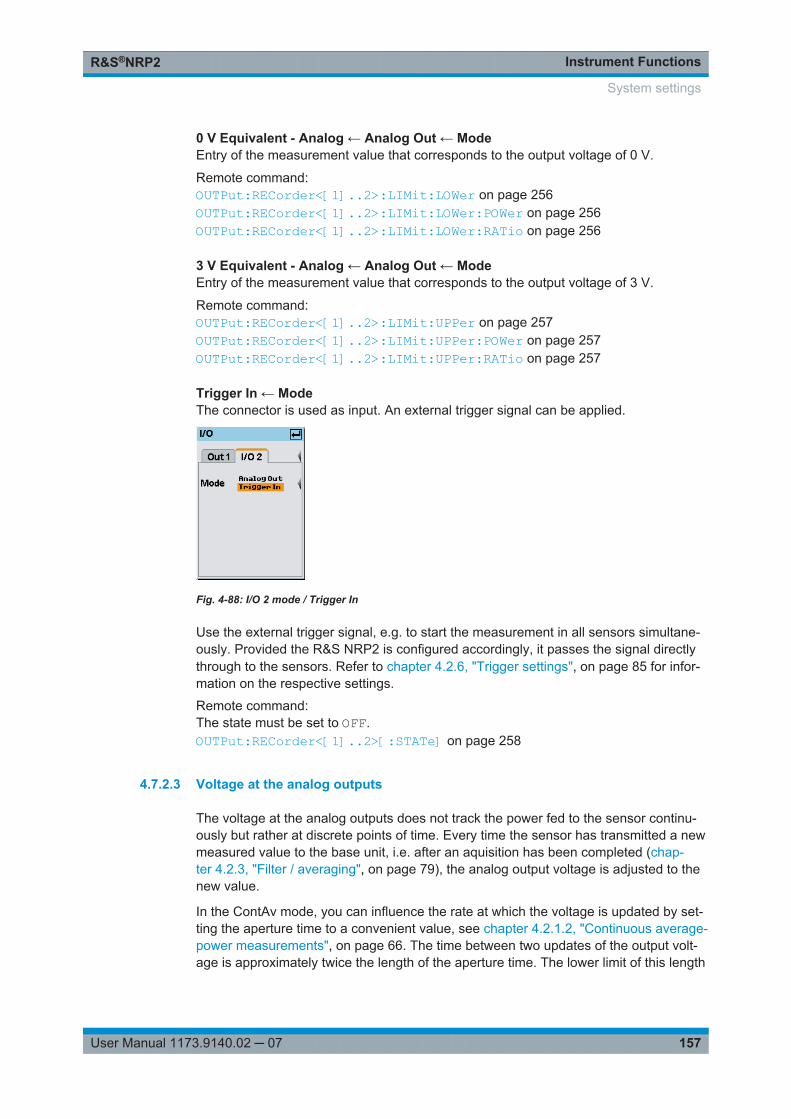
Instrument FunctionsR&S®NRP2
157User Manual 1173.9140.02 ─ 07
0 V Equivalent - Analog ← Analog Out ← ModeEntry of the measurement value that corresponds to the output voltage of 0 V.
Remote command: OUTPut:RECorder<[1]..2>:LIMit:LOWer on page 256OUTPut:RECorder<[1]..2>:LIMit:LOWer:POWer on page 256OUTPut:RECorder<[1]..2>:LIMit:LOWer:RATio on page 256
3 V Equivalent - Analog ← Analog Out ← ModeEntry of the measurement value that corresponds to the output voltage of 3 V.
Remote command: OUTPut:RECorder<[1]..2>:LIMit:UPPer on page 257OUTPut:RECorder<[1]..2>:LIMit:UPPer:POWer on page 257OUTPut:RECorder<[1]..2>:LIMit:UPPer:RATio on page 257
Trigger In ← ModeThe connector is used as input. An external trigger signal can be applied.
Fig. 4-88: I/O 2 mode / Trigger In
Use the external trigger signal, e.g. to start the measurement in all sensors simultane-ously. Provided the R&S NRP2 is configured accordingly, it passes the signal directlythrough to the sensors. Refer to chapter 4.2.6, "Trigger settings", on page 85 for infor-mation on the respective settings.
Remote command: The state must be set to OFF.OUTPut:RECorder<[1]..2>[:STATe] on page 258
4.7.2.3 Voltage at the analog outputs
The voltage at the analog outputs does not track the power fed to the sensor continu-ously but rather at discrete points of time. Every time the sensor has transmitted a newmeasured value to the base unit, i.e. after an aquisition has been completed (chap-ter 4.2.3, "Filter / averaging", on page 79), the analog output voltage is adjusted to thenew value.
In the ContAv mode, you can influence the rate at which the voltage is updated by set-ting the aperture time to a convenient value, see chapter 4.2.1.2, "Continuous average-power measurements", on page 66. The time between two updates of the output volt-age is approximately twice the length of the aperture time. The lower limit of this length
System settings
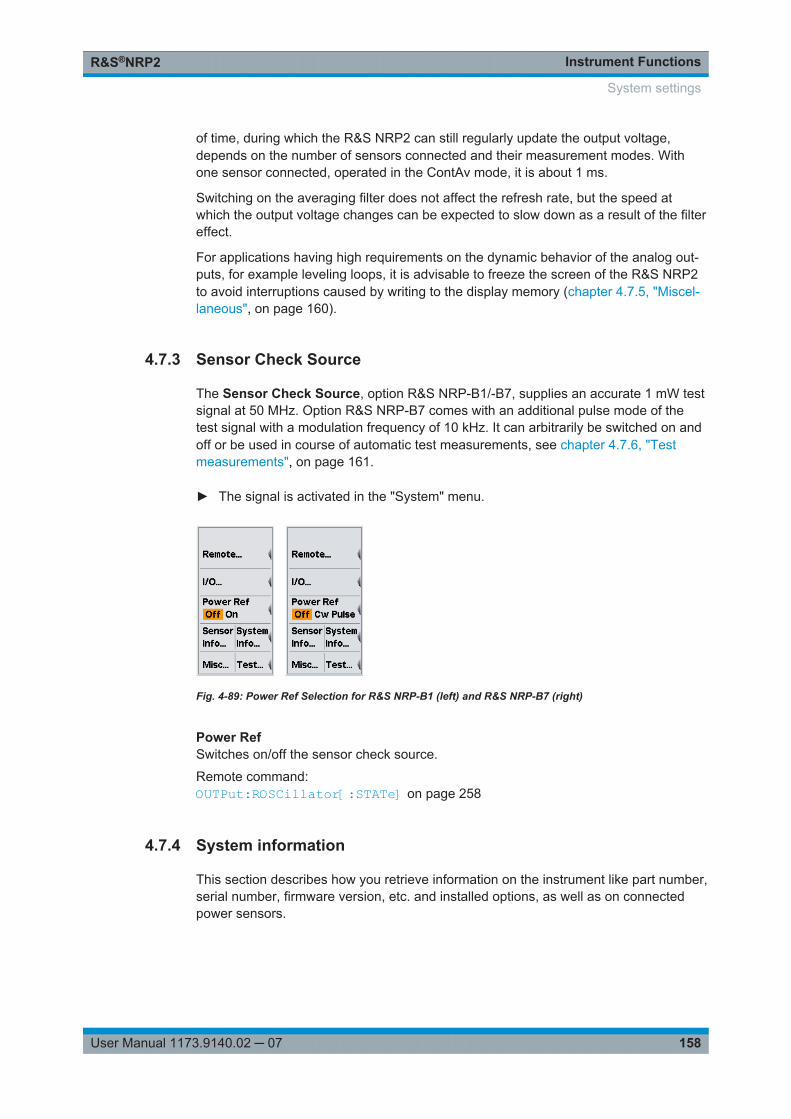
Instrument FunctionsR&S®NRP2
158User Manual 1173.9140.02 ─ 07
of time, during which the R&S NRP2 can still regularly update the output voltage,depends on the number of sensors connected and their measurement modes. Withone sensor connected, operated in the ContAv mode, it is about 1 ms.
Switching on the averaging filter does not affect the refresh rate, but the speed atwhich the output voltage changes can be expected to slow down as a result of the filtereffect.
For applications having high requirements on the dynamic behavior of the analog out-puts, for example leveling loops, it is advisable to freeze the screen of the R&S NRP2to avoid interruptions caused by writing to the display memory (chapter 4.7.5, "Miscel-laneous", on page 160).
4.7.3 Sensor Check Source
The Sensor Check Source, option R&S NRP-B1/-B7, supplies an accurate 1 mW testsignal at 50 MHz. Option R&S NRP-B7 comes with an additional pulse mode of thetest signal with a modulation frequency of 10 kHz. It can arbitrarily be switched on andoff or be used in course of automatic test measurements, see chapter 4.7.6, "Testmeasurements", on page 161.
► The signal is activated in the "System" menu.
Fig. 4-89: Power Ref Selection for R&S NRP-B1 (left) and R&S NRP-B7 (right)
Power RefSwitches on/off the sensor check source.
Remote command: OUTPut:ROSCillator[:STATe] on page 258
4.7.4 System information
This section describes how you retrieve information on the instrument like part number,serial number, firmware version, etc. and installed options, as well as on connectedpower sensors.
System settings
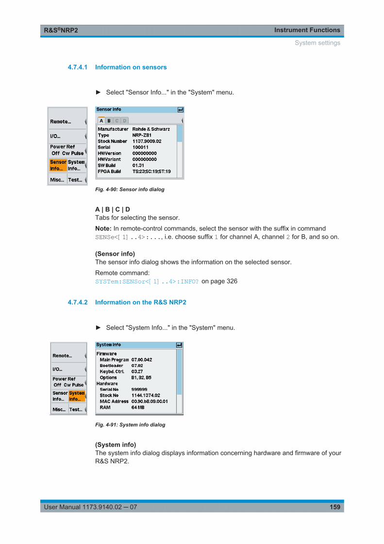
Instrument FunctionsR&S®NRP2
159User Manual 1173.9140.02 ─ 07
4.7.4.1 Information on sensors
► Select "Sensor Info..." in the "System" menu.
Fig. 4-90: Sensor info dialog
A | B | C | DTabs for selecting the sensor.
Note: In remote-control commands, select the sensor with the suffix in commandSENSe<[1]..4>:..., i.e. choose suffix 1 for channel A, channel 2 for B, and so on.
(Sensor info)The sensor info dialog shows the information on the selected sensor.
Remote command: SYSTem:SENSor<[1]..4>:INFO? on page 326
4.7.4.2 Information on the R&S NRP2
► Select "System Info..." in the "System" menu.
Fig. 4-91: System info dialog
(System info)The system info dialog displays information concerning hardware and firmware of yourR&S NRP2.
System settings
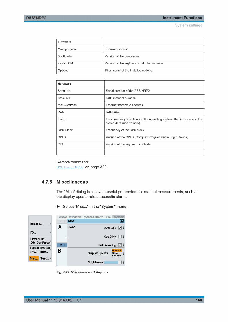
Instrument FunctionsR&S®NRP2
160User Manual 1173.9140.02 ─ 07
Firmware
Main program Firmware version
Bootloader Version of the bootloader.
Keybd. Ctrl. Version of the keyboard controller software.
Options Short name of the installed options.
Hardware
Serial No Serial number of the R&S NRP2.
Stock No R&S material number.
MAC Address Ethernet hardware address.
RAM RAM size.
Flash Flash memory size, holding the operating system, the firmware and thestored data (non-volatile).
CPU Clock Frequency of the CPU clock.
CPLD Version of the CPLD (Complex Programmable Logic Device).
PIC Version of the keyboard controller
Remote command: SYSTem:INFO? on page 322
4.7.5 Miscellaneous
The "Misc" dialog box covers useful parameters for manual measurements, such asthe display update rate or acoustic alarms.
► Select "Misc..." in the "System" menu.
Fig. 4-92: Miscellaneous dialog box
System settings
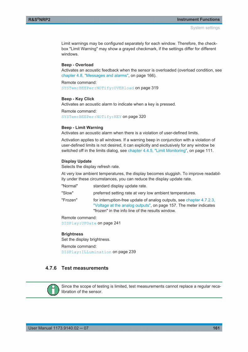
Instrument FunctionsR&S®NRP2
161User Manual 1173.9140.02 ─ 07
Limit warnings may be configured separately for each window. Therefore, the check-box "Limit Warning" may show a grayed checkmark, if the settings differ for differentwindows.
Beep - OverloadActivates an acoustic feedback when the sensor is overloaded (overload condition, seechapter 4.8, "Messages and alarms", on page 166).
Remote command: SYSTem:BEEPer:NOTify:OVERload on page 319
Beep - Key ClickActivates an acoustic alarm to indicate when a key is pressed.
Remote command: SYSTem:BEEPer:NOTify:KEY on page 320
Beep - Limit WarningActivates an acoustic alarm when there is a violation of user-defined limits.
Activation applies to all windows. If a warning beep in conjunction with a violation ofuser-defined limits is not desired, it can explicitly and exclusively for any window beswitched off in the limits dialog, see chapter 4.4.5, "Limit Monitoring", on page 111.
Display UpdateSelects the display refresh rate.
At very low ambient temperatures, the display becomes sluggish. To improve readabil-ity under these circumstances, you can reduce the display update rate.
"Normal" standard display update rate.
"Slow" preferred setting rate at very low ambient temperatures.
"Frozen" for interruption-free update of analog outputs, see chapter 4.7.2.3,"Voltage at the analog outputs", on page 157. The meter indicates"frozen" in the info line of the results window.
Remote command: DISPlay:UPDate on page 241
BrightnessSet the display brightness.
Remote command: DISPlay:ILLumination on page 239
4.7.6 Test measurements
Since the scope of testing is limited, test measurements cannot replace a regular reca-libration of the sensor.
System settings

Instrument FunctionsR&S®NRP2
162User Manual 1173.9140.02 ─ 07
The "Test..." function offers tests for the internal circuitry of the sensor (selftest 1) aswell as simple tests with applied RF (option R&S NRP-B1/-B7 required).
4.7.6.1 Internal sensor selftest
► Open the "Sensortest" dialog box in the "System"→"Test..." menu.
Fig. 4-93: Sensortest dialog box / page 1
The first page of the "Sensortest" dialog box covers the settings for performing aninternal selftest of the sensor without using the reference signal.
A | B | C | DTabs for selecting the sensor.
Note: In remote-control commands, select the sensor with the suffix in commandSENSe<[1]..4>:..., i.e. choose suffix 1 for channel A, channel 2 for B, and so on.
Selftest internal (with no signal)Starts a selftest of the sensor. A signal must not be applied.
The instrument indicates the corresponding states to internal self-test directly in themenu:● "...not tested" (prior to testing)● "...running" (in progress)● "...successful" (outcome)● "...failed" (outcome)
Test Report…Opens the "Sensor Selftest Report" window displaying the results of the internal selft-est.
The status bar of the report window shows type and serial number of the tested sen-sor, and the overall test result. The results of the individual tests are indicated below.
System settings
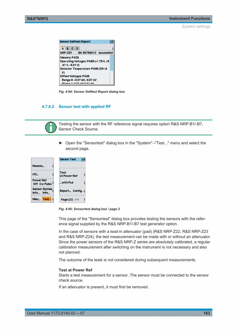
Instrument FunctionsR&S®NRP2
163User Manual 1173.9140.02 ─ 07
Fig. 4-94: Sensor Selftest Report dialog box
4.7.6.2 Sensor test with applied RF
Testing the sensor with the RF reference signal requires option R&S NRP-B1/-B7,Sensor Check Source.
► Open the "Sensortest" dialog box in the "System"→"Test..." menu and select thesecond page.
Fig. 4-95: Sensortest dialog box / page 2
This page of the "Sensortest" dialog box provides testing the sensors with the refer-ence signal supplied by the R&S NRP-B1/-B7 test generator option.
In the case of sensors with a lead-in attenuator (pad) (R&S NRP-Z22, R&S NRP-Z23and R&S NRP-Z24), the test measurement can be made with or without an attenuator.Since the power sensors of the R&S NRP-Z series are absolutely calibrated, a regularcalibration measurement after switching on the instrument is not necessary and alsonot planned.
The outcome of the tests is not considered during subsequent measurements.
Test at Power RefStarts a test measurement for a sensor. The sensor must be connected to the sensorcheck source.
If an attenuator is present, it must first be removed.
System settings
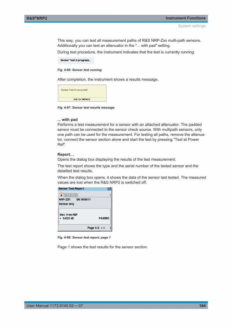
Instrument FunctionsR&S®NRP2
164User Manual 1173.9140.02 ─ 07
This way, you can test all measurement paths of R&S NRP-Zxx multi-path sensors.Additionally you can test an attenuator in the "... with pad" setting.
During test procedure, the instrument indicates that the test is currently running.
Fig. 4-96: Sensor test running
After completion, the instrument shows a results message.
Fig. 4-97: Sensor test results message
... with padPerforms a test measurement for a sensor with an attached attenuator. The paddedsensor must be connected to the sensor check source. With multipath sensors, onlyone path can be used for the measurement. For testing all paths, remove the attenua-tor, connect the sensor section alone and start the test by pressing "Test at PowerRef".
Report…Opens the dialog box displaying the results of the test measurement.
The test report shows the type and the serial number of the tested sensor and thedetailled test results.
When the dialog box opens, it shows the data of the sensor last tested. The measuredvalues are lost when the R&S NRP2 is switched off.
Fig. 4-98: Sensor test report, page 1
Page 1 shows the test results for the sensor section.
System settings
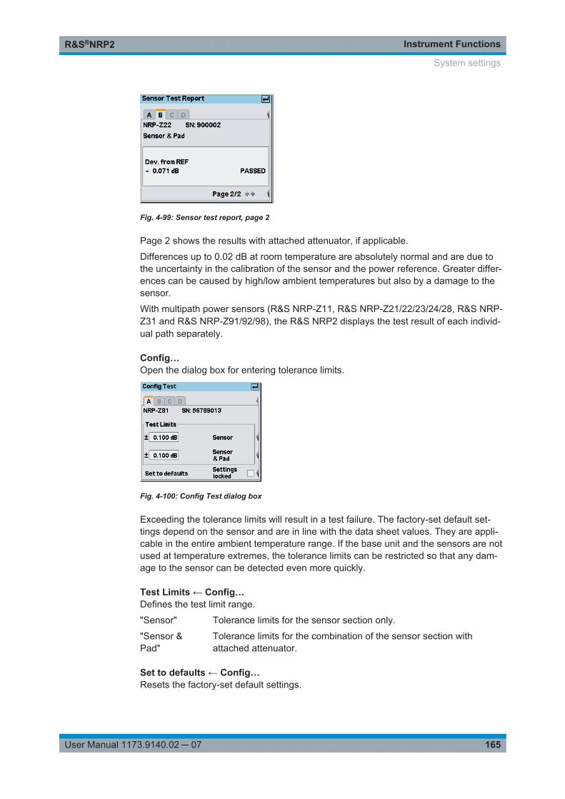
Instrument FunctionsR&S®NRP2
165User Manual 1173.9140.02 ─ 07
Fig. 4-99: Sensor test report, page 2
Page 2 shows the results with attached attenuator, if applicable.
Differences up to 0.02 dB at room temperature are absolutely normal and are due tothe uncertainty in the calibration of the sensor and the power reference. Greater differ-ences can be caused by high/low ambient temperatures but also by a damage to thesensor.
With multipath power sensors (R&S NRP-Z11, R&S NRP-Z21/22/23/24/28, R&S NRP-Z31 and R&S NRP-Z91/92/98), the R&S NRP2 displays the test result of each individ-ual path separately.
Config…Open the dialog box for entering tolerance limits.
Fig. 4-100: Config Test dialog box
Exceeding the tolerance limits will result in a test failure. The factory-set default set-tings depend on the sensor and are in line with the data sheet values. They are appli-cable in the entire ambient temperature range. If the base unit and the sensors are notused at temperature extremes, the tolerance limits can be restricted so that any dam-age to the sensor can be detected even more quickly.
Test Limits ← Config…Defines the test limit range.
"Sensor" Tolerance limits for the sensor section only.
"Sensor &Pad"
Tolerance limits for the combination of the sensor section withattached attenuator.
Set to defaults ← Config…Resets the factory-set default settings.
System settings

Instrument FunctionsR&S®NRP2
166User Manual 1173.9140.02 ─ 07
Settings locked ← Config…Protects the settings against being changed by mistake.
4.8 Messages and alarms
The R&S NRP2 displays a variety of different messages such as status messages,error messages, warnings or information on the screen, some in separate windows, orin the header.
4.8.1 Errors and warnings
Overload
Fig. 4-101: Error message / Overload
One or more sensors are subjected to overload.
NOTICE! Overload can destroy the sensor (depending on the amount of power and theduration of the overload condition).The upper measurement limit is specified in the data sheet for the sensor and can bedisplayed in the "Sensor Info" dialog box, see chapter 4.7.4, "System information",on page 158.
An alarm sounds when the message is displayed. The alarm can be disabled in the"Misc" dialog box, see chapter 4.7.5, "Miscellaneous", on page 160.
Overrange
Fig. 4-102: Error message / Overrange
This message is displayed only if the "Auto" range function is off and the operatingrange of the set path has been exceeded (only with R&S NRP-Zxx multi-path sensors),see chapter 4.2.4, "Measurement ranges", on page 83.
Messages and alarms
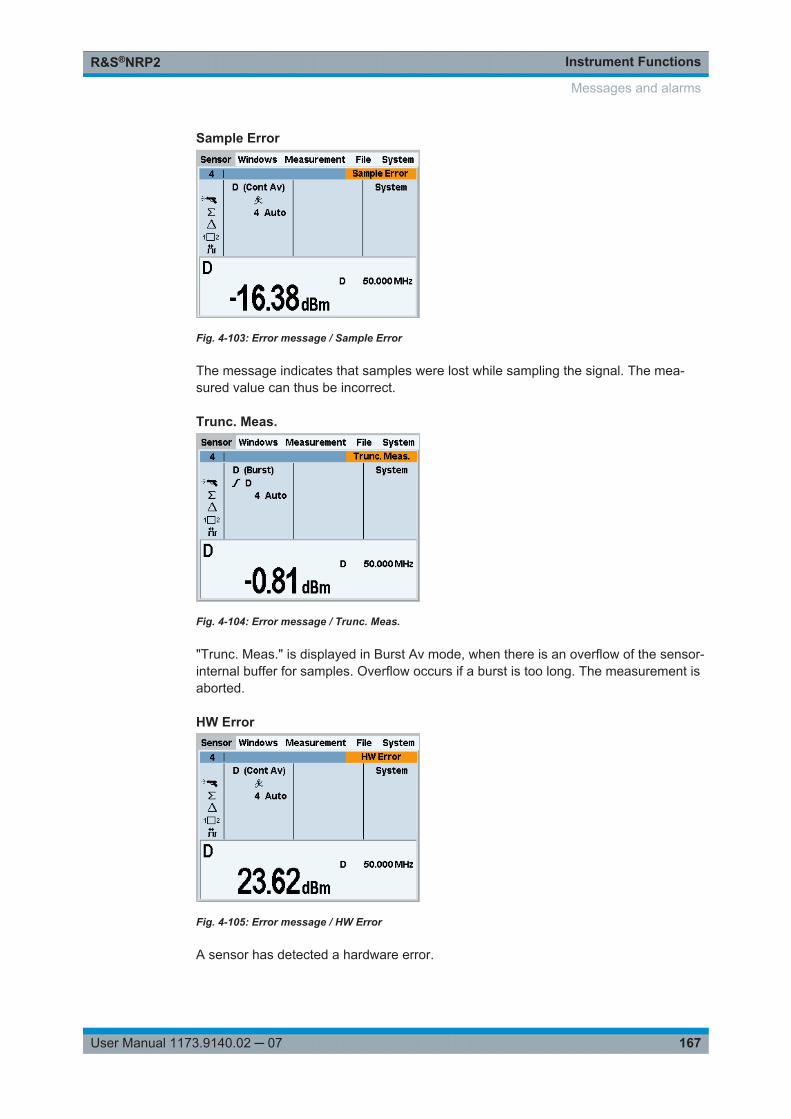
Instrument FunctionsR&S®NRP2
167User Manual 1173.9140.02 ─ 07
Sample Error
Fig. 4-103: Error message / Sample Error
The message indicates that samples were lost while sampling the signal. The mea-sured value can thus be incorrect.
Trunc. Meas.
Fig. 4-104: Error message / Trunc. Meas.
"Trunc. Meas." is displayed in Burst Av mode, when there is an overflow of the sensor-internal buffer for samples. Overflow occurs if a burst is too long. The measurement isaborted.
HW Error
Fig. 4-105: Error message / HW Error
A sensor has detected a hardware error.
Messages and alarms
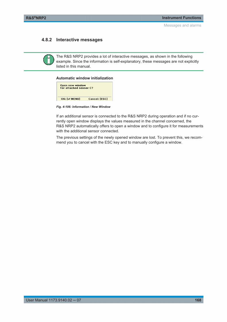
Instrument FunctionsR&S®NRP2
168User Manual 1173.9140.02 ─ 07
4.8.2 Interactive messages
The R&S NRP2 provides a lot of interactive messages, as shown in the followingexample. Since the information is self-explanatory, these messages are not explicitlylisted in this manual.
Automatic window initialization
Fig. 4-106: Information / New Window
If an additional sensor is connected to the R&S NRP2 during operation and if no cur-rently open window displays the values measured in the channel concerned, theR&S NRP2 automatically offers to open a window and to configure it for measurementswith the additional sensor connected.
The previous settings of the newly opened window are lost. To prevent this, we recom-mend you to cancel with the ESC key and to manually configure a window.
Messages and alarms
Remote Control FundamentalsR&S®NRP2
169User Manual 1173.9140.02 ─ 07
5 Remote Control FundamentalsThe Power Meter R&S NRP2 is equipped with various interfaces that can be connec-ted to a controller for remote control.
● IEC/IEEE-bus interface (standard equipment) in line with the standards IEC60625.1 (IEEE 488.1) and IEC 60625.2 (IEEE 488.2)
● Ethernet 10/100 BASE T interface.● USB1.1 interface for remote control and firmware update.
Connectors are installed at the rear of the power meter. The interfaces support theSCPI (Standard Commands for Programmable Instruments) standard, version 1999.0of May 1999. The SCPI standard is based on the IEEE 488.2 standard and defines astandardized command language for controlling measuring and test instruments withfunctions beyond the scope of the IEEE 488.2 standard. In addition to the commands,error handling and status management are also described.
The present chapter explains the differences between remote control and manual con-trol, familiarizes the user with fundamentals of remote control and describes the statusreporting system as well as the procedure for connecting a PC for remote control.
5.1 Differences between Remote Control and ManualControl
The manual control of the R&S NRP2 is designed for ergonomic operation. Thismeans, among other things, that certain parameters are assigned default values thatcannot be changed and that specific changes of device settings influence other set-tings. In the remote control mode, all settings can be changed and the user has tomake sure that the device is correctly set for the measurement to be performed. Wetherefore recommend performing a reset (*RST on page 198 or SYSTem:PRESeton page 325) prior to a remote control measurement so that the device is placed in adefined state.
5.1.1 Display
In the remote mode, the display of measured values can be disabled (set SYS-Tem:SPEed to FAST); the display is cleared except for a status line at the top of thescreen. Blanking of menu elements that need not be continually updated increases thedata processing speed. The display can be reactivated by setting the SCPI commandSYSTem:SPEed to NORM. The backlighting can also be completely switched off by set-ting command DISPlay:ILLumination to OFF, but this does not affect the speed.
In the remote mode, the menu line at the upper screen edge is blanked and replacedby the indication "Remote Mode". The R&S NRP2 is able to emulate different powermeters with alternative command sets. The currently used command set is indicated inthe middle of the status line. The SCPI error queue can be displayed using the topmostsoftkey (labeled "Error List..."). If the LLO character is displayed in the upper status
Differences between Remote Control and Manual Control
Remote Control FundamentalsR&S®NRP2
170User Manual 1173.9140.02 ─ 07
line, the keyboard including ESC/LOCAL has been disabled via the LLO command. Inthis case, returning to local mode is only possible with the remote control commandGTL or by a power-on reset.
5.1.2 Measurement Modes
To simplify operation in the manual mode, preset values are used in some cases forthe trigger system (TRIGger command) and the timing of the measurement(SENSe[1..4]:TIMing:EXCLude:STARt and :STOP) when a measurement modesuch as "ContAv", "Burst", "Timeslot" or "Trace" is selected, see table 5-3, Automaticsettings for manual selection of a measurement mode. This is not the case in theremote control mode. Here the trigger system and the timing can be configured by theuser as required.
5.1.3 Calculate Blocks
The R&S NRP2 manages 8 internal calculate blocks. Each calculate block has twoinput channels (primary and secondary channel) to which one of up to 4 power sensorscan be assigned. The channels can be processed together by means of a selectablefunction. The result is available at the output of the calculate block. In the manualmode, the measurement results of the first four calculate blocks (chapter 6.5, "CALCu-late (Configuration of Calculate Blocks)", on page 224) are shown in windows 1 to 4,while 8 calculate blocks are available in the remote control mode.
5.2 Connecting a Controller to the Base Unit
5.2.1 Settings in Base Unit
Before a link can be established between the controller and the R&S NRP2, theR&S NRP2 must be assigned a corresponding address.
In the manual control mode, the address is set in the "System" > "Remote" dialog box,see chapter 4.7.1, "Configuring the remote control interfaces", on page 145.
In remote control mode, the SYSTem:COMMunication:.. commands serve this pur-pose.
GPIB configuration (IEC/IEEE bus):
1. Select "GPIB" as the active interface.
2. Enter the GPIB address. Any value between 0 and 30 is permissible.
USB configuration:
► Select "USB" as the active interface.
Connecting a Controller to the Base Unit
Remote Control FundamentalsR&S®NRP2
171User Manual 1173.9140.02 ─ 07
The "VISA address string" suitable for the instrument is displayed in the dialog box.The R&S NRP2 has a fixed, unchangeable address comprising the manufacturernumber, an instrument number and the serial number of the instrument.USB::<vendor ID>::<product ID>::<serial number>[::INSTR]
VXI11 configuration:
1. Select "VXI11" as the active interface.
2. Choose "Manual" or "DHCP" IP address configuration.If "DHCP" is chosen, IP address, subnet mask and gateway address are retrievedfrom a DHCP server. The DCHP server must be available in the network. No fur-ther steps are required.
3. If "Manual" is selected, enter the "IP address" assigned by the network administra-tor to the R&S NRP2.In large networks, specification of additional addresses may be required for linksetup, e.g. gateway and subnet mask, which are known to the network administra-tor.
Ethernet configuration:
1. Select "Ethernet" as the active interface .
2. Choose "Manual" or "DHCP" IP address configuration.If "DHCP" is chosen, IP address, subnet mask and gateway address are retrievedfrom a DHCP server. The DCHP server must be available in the network. No fur-ther steps are required.
3. If "Manual" is selected, enter the "IP address" assigned by the network administra-tor to the R&S NRP2.In large networks, specification of additional addresses may be required for linksetup, for example. gateway and subnet mask, which are known to the networkadministrator.
4. Enter the port address ("PortNo"). Incoming connections from a controller have touse this port number in order to establish a connection to the R&S NRP2.
5. Define the IEEE protocol mode. For example select "IEEE 488.0" mode in order touse raw socket communication. See also chapter A.2.3, "Ethernet interface",on page 361.
Connecting a Controller to the Base Unit
Remote Control FundamentalsR&S®NRP2
172User Manual 1173.9140.02 ─ 07
5.2.2 Hardware Requirements
Risk of network failureBefore connecting the instrument to the network or configuring the network, consultyour network administrator. Errors may affect the entire network.
GPIB (IEC/IEEE bus)
In order to remote control the R&S NRP2 via the GPIB bus, a controller with therespective bus interface and the bus cable is required.
USB
The R&S NRP2 automatically recognizes a controller connected to the USB1.1 inter-face.
Ethernet/ VXI11
Controlling the R&S NRP2 via the Ethernet interface requires a computer with networkcard and LAN cables to connect the computer and the R&S NRP2 controller with theEthernet.
5.3 Switchover to Remote Control (REMOTE)
It is assumed that a link has been established between the controller and theR&S NRP2 has been correctly configured.
After power up, the R&S NRP2 is always in manual control mode "LOCAL". TheR&S NRP2 switches to remote control irrespective of the selected interface as soon asit receives a SCPI command. All settings are maintained when the device switches toremote mode, except for the setting listed in table 5-1.
5.4 Return to Manual Operation (LOCAL)
In the remote mode, all front-panel controls are disabled, except for the ESC/LOCALkey and the topmost softkey. The softkey used to open the window with the SCPI errorqueue. The device remains in remote mode until it is switched back to manual controleither by using the front panel ESC/LOCAL or with the remote control command GTL.
Switchover to Remote Control (REMOTE)
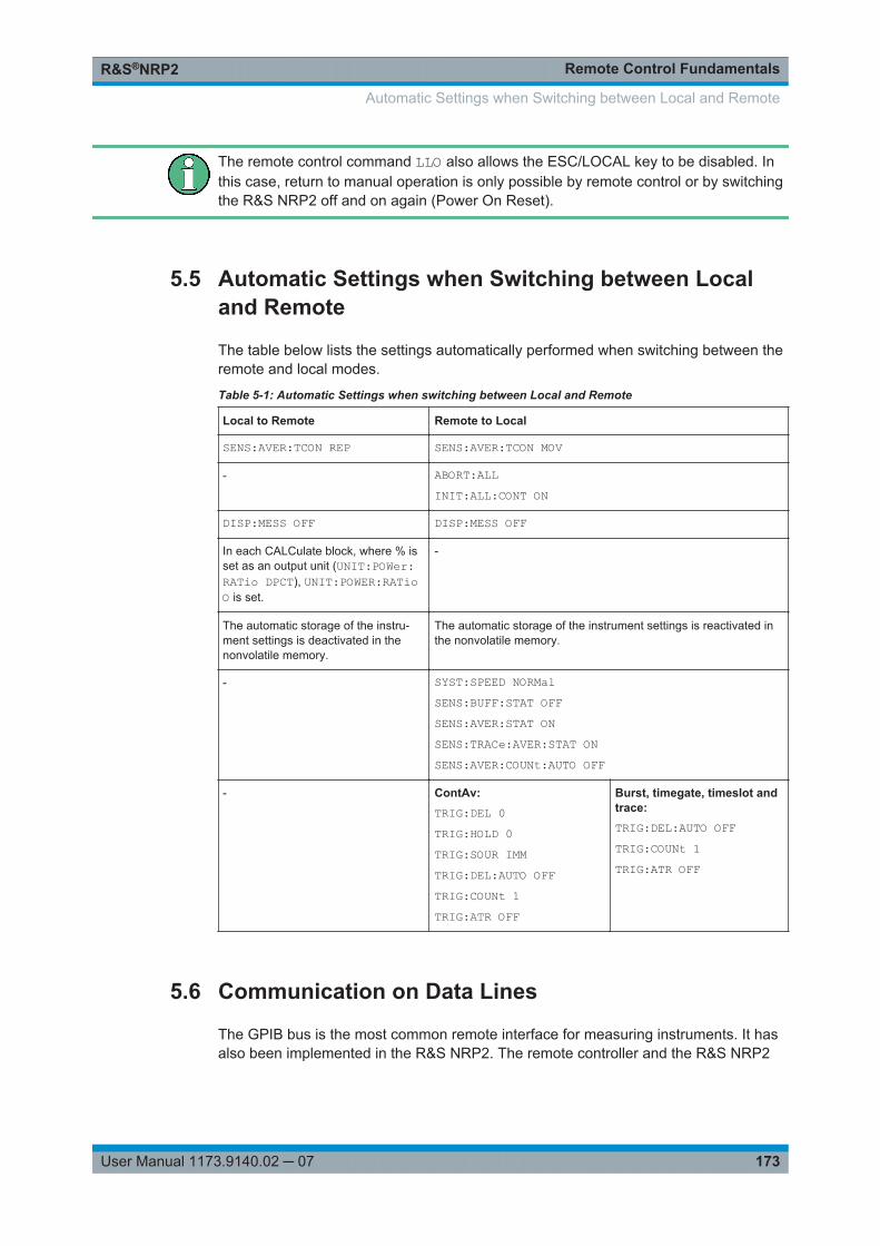
Remote Control FundamentalsR&S®NRP2
173User Manual 1173.9140.02 ─ 07
The remote control command LLO also allows the ESC/LOCAL key to be disabled. Inthis case, return to manual operation is only possible by remote control or by switchingthe R&S NRP2 off and on again (Power On Reset).
5.5 Automatic Settings when Switching between Localand Remote
The table below lists the settings automatically performed when switching between theremote and local modes.
Table 5-1: Automatic Settings when switching between Local and Remote
Local to Remote Remote to Local
SENS:AVER:TCON REP SENS:AVER:TCON MOV
- ABORT:ALLINIT:ALL:CONT ON
DISP:MESS OFF DISP:MESS OFF
In each CALCulate block, where % isset as an output unit (UNIT:POWer:RATio DPCT), UNIT:POWER:RATioO is set.
-
The automatic storage of the instru-ment settings is deactivated in thenonvolatile memory.
The automatic storage of the instrument settings is reactivated inthe nonvolatile memory.
- SYST:SPEED NORMalSENS:BUFF:STAT OFFSENS:AVER:STAT ONSENS:TRACe:AVER:STAT ONSENS:AVER:COUNt:AUTO OFF
- ContAv:TRIG:DEL 0TRIG:HOLD 0TRIG:SOUR IMMTRIG:DEL:AUTO OFFTRIG:COUNt 1TRIG:ATR OFF
Burst, timegate, timeslot andtrace:TRIG:DEL:AUTO OFFTRIG:COUNt 1TRIG:ATR OFF
5.6 Communication on Data Lines
The GPIB bus is the most common remote interface for measuring instruments. It hasalso been implemented in the R&S NRP2. The remote controller and the R&S NRP2
Automatic Settings when Switching between Local and Remote
Remote Control FundamentalsR&S®NRP2
174User Manual 1173.9140.02 ─ 07
communicate by means of messages. The messages sent on the data lines (chap-ter A.2, "Remote control interfaces", on page 354) can be divided into two groups:
● Interface messages● Device-dependent messages
5.6.1 Interface Messages
Interface messages are transmitted on the data lines of the IEC/IEEE bus when theATN control line is active. Interface messages allow the controller and the instrumentto communicate and can only be sent by a controller which serves as the IEC/IEEE-bus controller. Interface commands can be further classified as:
● common commands● addressed commands
Common commands affect all devices connected to the IEC/IEEE bus without requir-ing an address, whereas addressed commands only affect devices addressed as a lis-tener. The interface messages relevant for the instrument are described in chapter A.2.1.5, "Interface messages", on page 357.
5.6.2 Device-Dependent Messages (Commands and Responses)
Device-dependent messages are transmitted on the data lines of the IEC/IEEE buswhen the ATN control line is not active. The ASCII code is used. Device-dependentmessages are classified according to the direction in which they are sent:
5.6.2.1 Commands
Commands are messages sent by the controller to the R&S NRP2. They control thedevice functions and request information. The commands are classified
according to the effect they have on the device:
● Setting commandstrigger device settings, e.g. an device reset or a configuration of the trigger system.
● Queriescause device data to be provided in the output queue, where they can be fetchedvia the IEC/IEEE bus. Queries are available for most of the setting commands.They are obtained by adding a question mark to the setting command.
according to their definition in the IEEE 488.2 and SCPI 1999.0 standard:
● Common commandsare precisely defined in the IEEE 488.2 standard in terms of function and notation.They relate to functions such as the management of standardized status registers,resetting and self test.
● Device-specific commandsrelate to functions that depend on device characteristics such as the frequency set-ting. Many of these commands are also standardized by the SCPI Consortium
Communication on Data Lines
Remote Control FundamentalsR&S®NRP2
175User Manual 1173.9140.02 ─ 07
(chapter 5.7.1, "SCPI Standard", on page 175). The standard allows device-spe-cific extensions of commands.
Parallelism
● Overlapping commandscan be executed while another command is being executed.
● Sequential commandscan only be executed when the execution of all other commands is completed.
In the R&S NRP2, only the remote control commands INIT:IMM andCAL:ZERO:AUTO ONCE can overlap with other commands.
5.6.2.2 Responses
Responses are messages sent by the device to the controller after a query. This maybe measurement results, for instance, or device status information.
5.7 Structure and Syntax of device-dependent Messages
5.7.1 SCPI Standard
SCPI (Standard Commands for Programmable Instruments) describes a standardizedcommand set for the programming of instruments regardless of the type of instrumentor manufacturer. The objective of the SCPI Consortium is to standardize device-spe-cific commands as far as possible. For this purpose, a device model has been devel-oped which defines identical functions within a device or between different devices.Command systems have been created and assigned to these functions so that it ispossible to address identical functions with the same commands. The command sys-tems have an hierarchical structure. The SCPI command tree, figure 5-1 shows thistree structure, using details from the SENSe command system which selects the mea-surement to be performed by the device. Most of the other examples of command syn-tax and structure are taken from this command system. SCPI is based on the IEEE488.2 standard, i.e. it uses the same syntax elements and the common commandsdefined in IEEE 488.2. The syntax of the responses is subjected to somewhat stricterrules than those specified by the IEEE 488.2 standard ( chapter 5.7.4, "Responses toQueries", on page 179).
5.7.2 Command Structure
Commands consist of a header and usually one or several parameters. Header andparameters are separated by a white space (ASCII code 0 to 9, 11 to 32 decimal, e.g.
Structure and Syntax of device-dependent Messages
Remote Control FundamentalsR&S®NRP2
176User Manual 1173.9140.02 ─ 07
space). The headers may be composed of several keywords. The query is created byappending a question mark directly to the header.
5.7.2.1 Common Commands
Device-independent commands consist of a header preceded by an asterisk (*). Theheader may be followed by one or several parameters.
Example:
*RST RESET Resets the instrument.
*ESE 253 EVENT STATUSENABLE
Sets the bits of the standard event status enable register.
*ESR? EVENT STATUS QUERY Queries the contents of the standard event status register.
5.7.2.2 Device-specific Commands
Hierarchy
Device-specific commands have a hierarchical structure, see SCPI command tree, fig-ure 5-1. The various levels are represented by compound headers. Headers at thehighest level (root level) have one keyword only. This keyword describes an entirecommand system.
Example: SENSe[1..4]This keyword denotes the command system SENSe<n>.
For lower-level commands, the full path has to be specified, starting with the highestlevel in the left-most position. The individual keywords are separated by a colon ":".
Structure and Syntax of device-dependent Messages
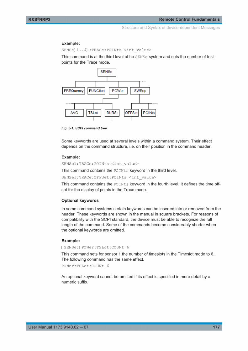
Remote Control FundamentalsR&S®NRP2
177User Manual 1173.9140.02 ─ 07
Example: SENSe[1..4]:TRACe:POINts <int_value>This command is at the third level of he SENSe system and sets the number of testpoints for the Trace mode.
Fig. 5-1: SCPI command tree
Some keywords are used at several levels within a command system. Their effectdepends on the command structure, i.e. on their position in the command header.
Example: SENSe1:TRACe:POINts <int_value>This command contains the POINts keyword in the third level.SENSe1:TRACe:OFFSet:POINts <int_value>This command contains the POINts keyword in the fourth level. It defines the time off-set for the display of points in the Trace mode.
Optional keywords
In some command systems certain keywords can be inserted into or removed from theheader. These keywords are shown in the manual in square brackets. For reasons ofcompatibility with the SCPI standard, the device must be able to recognize the fulllength of the command. Some of the commands become considerably shorter whenthe optional keywords are omitted.
Example: [SENSe:]POWer:TSLot:COUNt 6This command sets for sensor 1 the number of timeslots in the Timeslot mode to 6.The following command has the same effect.POWer:TSLot:COUNt 6
An optional keyword cannot be omitted if its effect is specified in more detail by anumeric suffix.
Structure and Syntax of device-dependent Messages
Remote Control FundamentalsR&S®NRP2
178User Manual 1173.9140.02 ─ 07
Example: SENSe2:POWer:TSLot:COUNt 6This command sets for sensor 2 the number of timeslots in the Timeslot mode to 6.Keyword SENSe cannot be omitted.
Long and short form
The keywords have a long and a short form. The keyword may be entered in short or inlong form; other abbreviations are not allowed. The short form uses the first four char-acters of the long form. If the fourth character is a vowel and the long form consists ofmore than four characters, only the first three characters are used for the short form.The short form is shown by upper-case characters, and the long form is the entire key-word.
Upper case and lower case notation only serves to distinguish the two forms in themanual, the instrument itself is case-insensitive.
Example: STATus:QUEStionable:ENABle 1 and STAT:QUES:ENAB 1
Parameters
The parameter must be separated from the header by a white space. If a commandcontains several parameters, they have to be separated by a comma (,). Some of thecommands allow the specification of the parameters MINimum, MAXimum andDEFault. For a description of the parameter types chapter 5.7.5, "Parameters",on page 180.
Example: TIMing:EXCLude:STARt? MINimumResponse: 0This query asks for the minimum setting value.
Numeric suffix
If a device has several identical functions or features, e.g. inputs, the desired functioncan be selected by a suffix to the command. Commands without a suffix are interpre-ted as having a suffix of 1.
Example: SENSe2:FUNCtion "POWer:AVG"This command sets the measurement mode of sensor 2 to the ContAv mode.
5.7.3 Structure of a Program Message
A program message may contain one or several commands. Several commands in aprogram message are separated by a semicolon (;). If the next command belongs to a
Structure and Syntax of device-dependent Messages
Remote Control FundamentalsR&S®NRP2
179User Manual 1173.9140.02 ─ 07
different command system, the semicolon is followed by a colon. The colon stands forthe root node of the command tree.
Example: SYSTem:TIME 20,30,00;:SENSe:FUNCtion "POWer:AVG"This program message contains two commands. The first command belongs to theSYSTem system and is used to set the time of the system clock. The second commandbelongs to the SENSe system and must be preceded by a colon. Otherwise confusionmight be caused if the SYSTem tree also had a subordinate SENSe node. In this case, itwould be possible to omit the introductory keyword SYSTem. (see the following explan-ation).
If the successive commands belong to the same system and therefore have one orseveral common levels, the program message may be abbreviated. The second com-mand following the semicolon then starts at the level that is below the common levels.The colon after the semicolon must be omitted in this case.
Example: SENSe2:TIMing:STARt 10; SENSe2:TIMing:STOP 10This program message contains two commands separated by a semicolon. Both com-mands belong to the SENSe system and its TIMing subsystem, i.e. they have twocommon levels.In the abbreviated program message the second command starts at the level belowSENSe:TIMing. The colon after the semicolon has to be omitted.
The short form of the program message is:SENSe2:TIMing:STARt 10; STOP 10
A new program message always starts with the full path however.
Example: SENSe2:TIMing:STARt 10SENSe2:TIMing:STOP 10
Processing of a program message is aborted if an error occurs. If only sensor 2 is con-nected to a multichannel device, for example, the program messageSENS1:FREQ 50 GHZ;:SENS2:FREQ 50 GHZwill be aborted after the first command and a second frequency setting will not be per-formed.
5.7.4 Responses to Queries
Unless otherwise expressly specified, a query is defined for each command. The queryis created by appending a question mark to the associated command.
Structure and Syntax of device-dependent Messages
Remote Control FundamentalsR&S®NRP2
180User Manual 1173.9140.02 ─ 07
Some of the SCPI rules for query responses are stricter than those of the IEEE 488.2standard:● The required value is sent without header.
Example:SENSe:AVERage:TCONTrol?Response: MOV
● Maximum and minimum values as well as all other quantities queried by a specialtext parameter are returned as numeric valuesExample:SENSe:POWer:TSLot:COUNt? MAXimumResponse: 26
● Numeric values are output without a unit. Physical quantities refer to the basic unitsor to the units set with the UNIT command.Example:SENSe3:FREQuency?Response: 1.000000E06 (for 1 MHz)
● Boolean values are returned as 0 (for OFF) and 1 (for ON).Example:SYSTem:BEEPer:STATe?Response: 1
● Character data is returned in short form (chapter 5.7.5, "Parameters",on page 180).Example:UNIT2:POWer?Response: DBM
5.7.5 Parameters
Most commands require the specification of a parameter. Parameters must be separa-ted from the header by a white space. Parameters may be specified as numeric val-ues, Boolean parameters, character data, strings or block data. The type of parameterrequired for the specific command as well as the permissible value range are descri-bed together with the commands.
Numeric values
Numeric values may be entered in any customary form, i.e. with sign, decimal pointand exponent. If the values exceed the resolution of the device, they will be roundedoff. Values between -9.9E37 and +9.9E37 can be entered. The exponent is denoted by"E" or "e". The exponent alone must not be used.
Units
Physical quantities may be stated with the unit. Permissible prefixes for the unit are G(Giga), MA (Mega, MHZ is also allowed), K (kilo), M (milli), U (micro) and N (nano). If nounit is specified, the basic unit will be used.
Structure and Syntax of device-dependent Messages
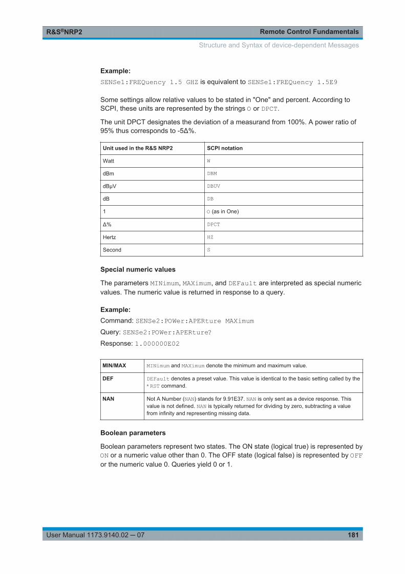
Remote Control FundamentalsR&S®NRP2
181User Manual 1173.9140.02 ─ 07
Example: SENSe1:FREQuency 1.5 GHZ is equivalent to SENSe1:FREQuency 1.5E9
Some settings allow relative values to be stated in "One" and percent. According toSCPI, these units are represented by the strings O or DPCT.
The unit DPCT designates the deviation of a measurand from 100%. A power ratio of95% thus corresponds to -5Δ%.
Unit used in the R&S NRP2 SCPI notation
Watt W
dBm DBM
dBµV DBUV
dB DB
1 O (as in One)
Δ% DPCT
Hertz HZ
Second S
Special numeric values
The parameters MINimum, MAXimum, and DEFault are interpreted as special numericvalues. The numeric value is returned in response to a query.
Example: Command: SENSe2:POWer:APERture MAXimumQuery: SENSe2:POWer:APERture?Response: 1.000000E02
MIN/MAX MINimum and MAXimum denote the minimum and maximum value.
DEF DEFault denotes a preset value. This value is identical to the basic setting called by the*RST command.
NAN Not A Number (NAN) stands for 9.91E37. NAN is only sent as a device response. Thisvalue is not defined. NAN is typically returned for dividing by zero, subtracting a valuefrom infinity and representing missing data.
Boolean parameters
Boolean parameters represent two states. The ON state (logical true) is represented byON or a numeric value other than 0. The OFF state (logical false) is represented by OFFor the numeric value 0. Queries yield 0 or 1.
Structure and Syntax of device-dependent Messages
Remote Control FundamentalsR&S®NRP2
182User Manual 1173.9140.02 ─ 07
Example: Command: SENSe:POWer:BUFFered ONQuery: SENSe:POWer:BUFFered?Response: 1
Character data
Character data follows the syntax rules for keywords, i.e. it also has both a short and along form. They must be separated from the header by a white space same as anyparameter. A query returns the short form of the character data.
Example: Command: SENSe2:AVERage:TCONTrol MOVingQuery: SENSe2:AVERage:TCONTrol?Response: MOV
Strings
Strings must always be indicated in single or double quotes.
Example: SENSe1:FUNCtion:ON "POWer:AVG" orSENSe1:FUNCtion:ON 'POWer:AVG'
Block data
The block data format is suitable for the transmission of large data volumes. A com-mand with a block data parameter has the following structure:
Example: DISPlay:PIXMap?Response: #49600xxxxxxxx.....
The ASCII character # denotes the beginning of the data block. The next numeralspecifies the number of subsequent digits defining the length of the data block. In theexample above, the four digits specify a length of 9600 bytes. The data bytes follownext. During transmission of these data bytes, all terminators and other control dataare ignored.
Coupled commands
Setting one command influences the value of another command. According to SCPI1999, this should be avoided but it makes sense when user-friendly high-level mea-surement commands are to be provided to configure an entire section of the device atonce. The high-level commands CONFigure, FETCh, READ and MEASure are there-fore an exception to this rule.
Structure and Syntax of device-dependent Messages

Remote Control FundamentalsR&S®NRP2
183User Manual 1173.9140.02 ─ 07
5.8 Device Model and Command Processing
The device model shown in figure 5-2 was prepared from the point of view of the pro-cessing of remote control commands. The individual components operate independ-ently of each other and simultaneously. They communicate with each other by meansof messages.
Fig. 5-2: Device model for remote control
5.8.1 Input Unit
The input unit receives the commands in the form of characters from the remote con-trol interface and collects them in the input buffer. The input unit sends a message tothe command identification as soon as the input buffer is full or as soon as it receives adelimiter. The received data is processed in the parser (command identification).
5.8.2 Command Identification (Parser)
The parser analyzes the data received from the input unit. Data is processed in thesequence in which it was received. Syntax errors in the command are recognized andpassed on to the status reporting system. Following the syntax test, the value range ofthe data is verified and the setting is adapted. Only after the command has been com-pletely executed will the next command be processed.
5.8.3 Data Base and Device Hardware
The term "device hardware" refers to that part of the device which performs the mea-surement function.
The data base contains all parameters required for setting the device hardware. Set-ting commands cause a modification of the data set. Before the data is entered in thedata set, it is verified for compatibility both with the other data and with the device hard-ware. If the setting is not possible, an error message will be sent to the status reportingsystem and the setting will be ignored. After successful completion of the verification,the setting will immediately be performed.
If the setting influences the result calculation, the MEASuring bit is set in the statusoperation register until new measured values are available. The MEASuring bit isdescribed in more detail in the Status Reporting System section that follows. This bitmay be used for the synchronization of command processing. Queries cause the data-set management to send the desired data to the output unit.
Device Model and Command Processing
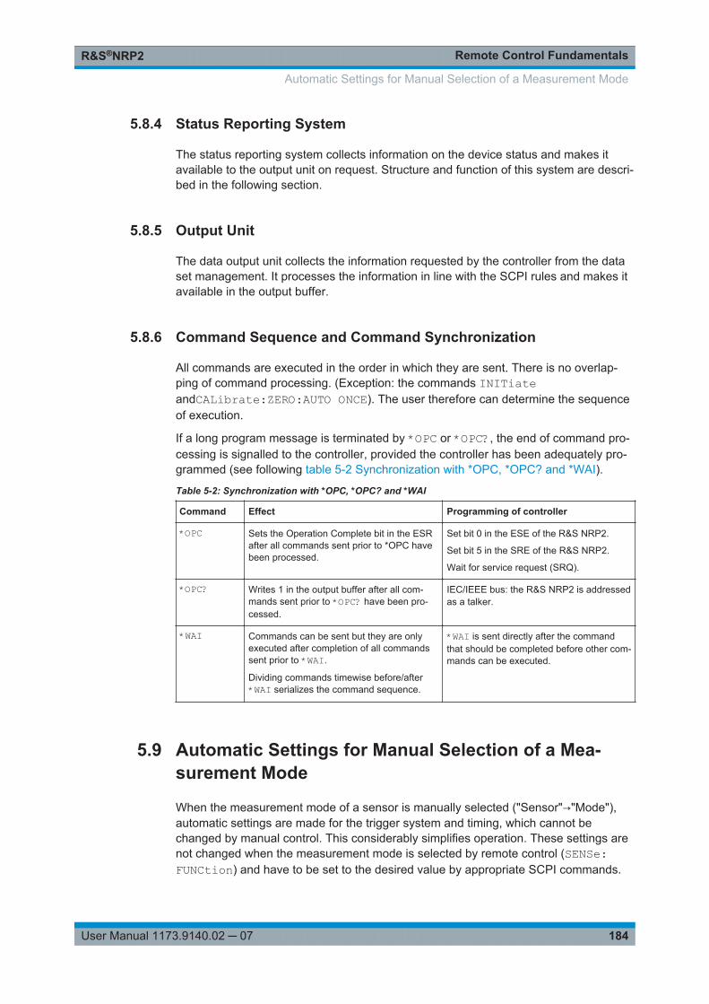
Remote Control FundamentalsR&S®NRP2
184User Manual 1173.9140.02 ─ 07
5.8.4 Status Reporting System
The status reporting system collects information on the device status and makes itavailable to the output unit on request. Structure and function of this system are descri-bed in the following section.
5.8.5 Output Unit
The data output unit collects the information requested by the controller from the dataset management. It processes the information in line with the SCPI rules and makes itavailable in the output buffer.
5.8.6 Command Sequence and Command Synchronization
All commands are executed in the order in which they are sent. There is no overlap-ping of command processing. (Exception: the commands INITiateandCALibrate:ZERO:AUTO ONCE). The user therefore can determine the sequenceof execution.
If a long program message is terminated by *OPC or *OPC?, the end of command pro-cessing is signalled to the controller, provided the controller has been adequately pro-grammed (see following table 5-2 Synchronization with *OPC, *OPC? and *WAI).
Table 5-2: Synchronization with *OPC, *OPC? and *WAI
Command Effect Programming of controller
*OPC Sets the Operation Complete bit in the ESRafter all commands sent prior to *OPC havebeen processed.
Set bit 0 in the ESE of the R&S NRP2.
Set bit 5 in the SRE of the R&S NRP2.
Wait for service request (SRQ).
*OPC? Writes 1 in the output buffer after all com-mands sent prior to *OPC? have been pro-cessed.
IEC/IEEE bus: the R&S NRP2 is addressedas a talker.
*WAI Commands can be sent but they are onlyexecuted after completion of all commandssent prior to *WAI.
Dividing commands timewise before/after*WAI serializes the command sequence.
*WAI is sent directly after the commandthat should be completed before other com-mands can be executed.
5.9 Automatic Settings for Manual Selection of a Mea-surement Mode
When the measurement mode of a sensor is manually selected ("Sensor"→"Mode"),automatic settings are made for the trigger system and timing, which cannot bechanged by manual control. This considerably simplifies operation. These settings arenot changed when the measurement mode is selected by remote control (SENSe:FUNCtion) and have to be set to the desired value by appropriate SCPI commands.
Automatic Settings for Manual Selection of a Measurement Mode
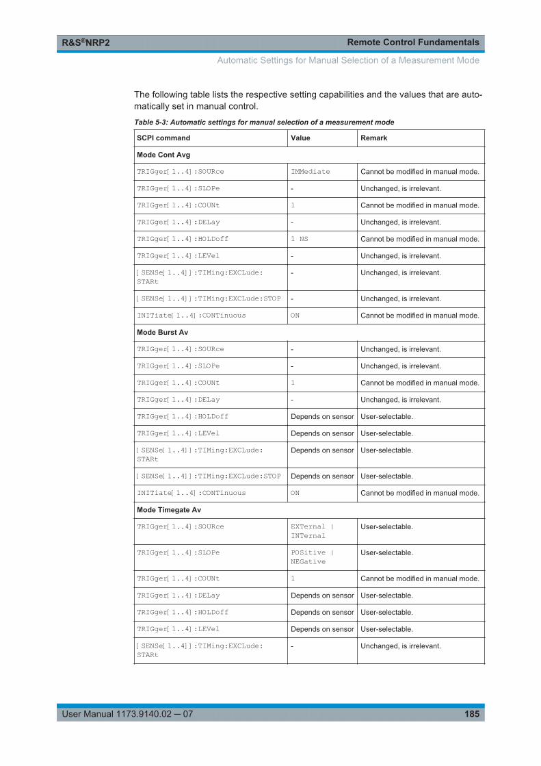
Remote Control FundamentalsR&S®NRP2
185User Manual 1173.9140.02 ─ 07
The following table lists the respective setting capabilities and the values that are auto-matically set in manual control.
Table 5-3: Automatic settings for manual selection of a measurement mode
SCPI command Value Remark
Mode Cont Avg
TRIGger[1..4]:SOURce IMMediate Cannot be modified in manual mode.
TRIGger[1..4]:SLOPe - Unchanged, is irrelevant.
TRIGger[1..4]:COUNt 1 Cannot be modified in manual mode.
TRIGger[1..4]:DELay - Unchanged, is irrelevant.
TRIGger[1..4]:HOLDoff 1 NS Cannot be modified in manual mode.
TRIGger[1..4]:LEVel - Unchanged, is irrelevant.
[SENSe[1..4]]:TIMing:EXCLude:STARt
- Unchanged, is irrelevant.
[SENSe[1..4]]:TIMing:EXCLude:STOP - Unchanged, is irrelevant.
INITiate[1..4]:CONTinuous ON Cannot be modified in manual mode.
Mode Burst Av
TRIGger[1..4]:SOURce - Unchanged, is irrelevant.
TRIGger[1..4]:SLOPe - Unchanged, is irrelevant.
TRIGger[1..4]:COUNt 1 Cannot be modified in manual mode.
TRIGger[1..4]:DELay - Unchanged, is irrelevant.
TRIGger[1..4]:HOLDoff Depends on sensor User-selectable.
TRIGger[1..4]:LEVel Depends on sensor User-selectable.
[SENSe[1..4]]:TIMing:EXCLude:STARt
Depends on sensor User-selectable.
[SENSe[1..4]]:TIMing:EXCLude:STOP Depends on sensor User-selectable.
INITiate[1..4]:CONTinuous ON Cannot be modified in manual mode.
Mode Timegate Av
TRIGger[1..4]:SOURce EXTernal |INTernal
User-selectable.
TRIGger[1..4]:SLOPe POSitive |NEGative
User-selectable.
TRIGger[1..4]:COUNt 1 Cannot be modified in manual mode.
TRIGger[1..4]:DELay Depends on sensor User-selectable.
TRIGger[1..4]:HOLDoff Depends on sensor User-selectable.
TRIGger[1..4]:LEVel Depends on sensor User-selectable.
[SENSe[1..4]]:TIMing:EXCLude:STARt
- Unchanged, is irrelevant.
Automatic Settings for Manual Selection of a Measurement Mode
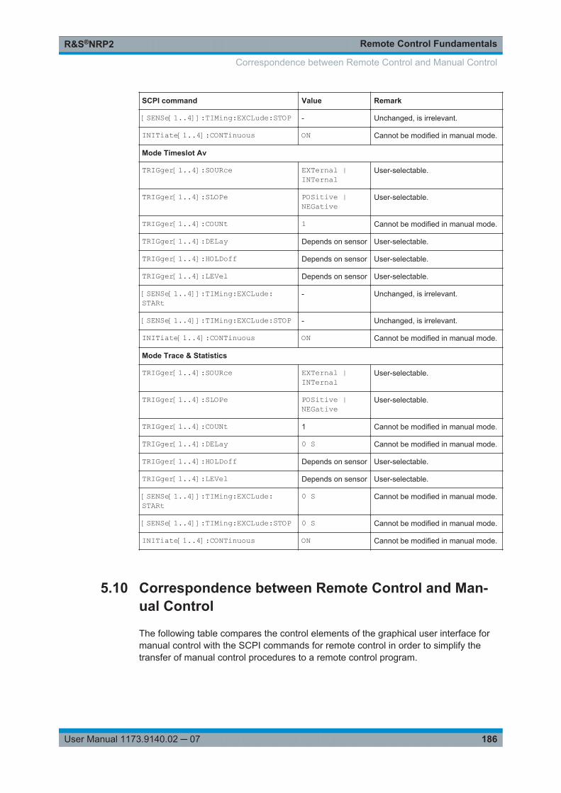
Remote Control FundamentalsR&S®NRP2
186User Manual 1173.9140.02 ─ 07
SCPI command Value Remark
[SENSe[1..4]]:TIMing:EXCLude:STOP - Unchanged, is irrelevant.
INITiate[1..4]:CONTinuous ON Cannot be modified in manual mode.
Mode Timeslot Av
TRIGger[1..4]:SOURce EXTernal |INTernal
User-selectable.
TRIGger[1..4]:SLOPe POSitive |NEGative
User-selectable.
TRIGger[1..4]:COUNt 1 Cannot be modified in manual mode.
TRIGger[1..4]:DELay Depends on sensor User-selectable.
TRIGger[1..4]:HOLDoff Depends on sensor User-selectable.
TRIGger[1..4]:LEVel Depends on sensor User-selectable.
[SENSe[1..4]]:TIMing:EXCLude:STARt
- Unchanged, is irrelevant.
[SENSe[1..4]]:TIMing:EXCLude:STOP - Unchanged, is irrelevant.
INITiate[1..4]:CONTinuous ON Cannot be modified in manual mode.
Mode Trace & Statistics
TRIGger[1..4]:SOURce EXTernal |INTernal
User-selectable.
TRIGger[1..4]:SLOPe POSitive |NEGative
User-selectable.
TRIGger[1..4]:COUNt 1 Cannot be modified in manual mode.
TRIGger[1..4]:DELay 0 S Cannot be modified in manual mode.
TRIGger[1..4]:HOLDoff Depends on sensor User-selectable.
TRIGger[1..4]:LEVel Depends on sensor User-selectable.
[SENSe[1..4]]:TIMing:EXCLude:STARt
0 S Cannot be modified in manual mode.
[SENSe[1..4]]:TIMing:EXCLude:STOP 0 S Cannot be modified in manual mode.
INITiate[1..4]:CONTinuous ON Cannot be modified in manual mode.
5.10 Correspondence between Remote Control and Man-ual Control
The following table compares the control elements of the graphical user interface formanual control with the SCPI commands for remote control in order to simplify thetransfer of manual control procedures to a remote control program.
Correspondence between Remote Control and Manual Control
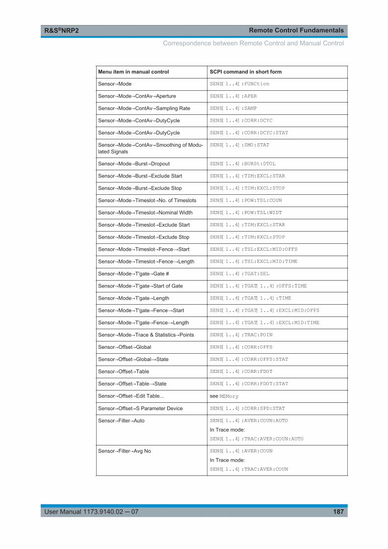
Remote Control FundamentalsR&S®NRP2
187User Manual 1173.9140.02 ─ 07
Menu item in manual control SCPI command in short form
Sensor→Mode SENS[1..4]:FUNCtion
Sensor→Mode→ContAv→Aperture SENS[1..4]:APER
Sensor→Mode→ContAv→Sampling Rate SENS[1..4]:SAMP
Sensor→Mode→ContAv→DutyCycle SENS[1..4]:CORR:DCYC
Sensor→Mode→ContAv→DutyCycle SENS[1..4]:CORR:DCYC:STAT
Sensor→Mode→ContAv→Smoothing of Modu-lated Signals
SENS[1..4]:SMO:STAT
Sensor→Mode→Burst→Dropout SENS[1..4]:BURSt:DTOL
Sensor→Mode→Burst→Exclude Start SENS[1..4]:TIM:EXCL:STAR
Sensor→Mode→Burst→Exclude Stop SENS[1..4]:TIM:EXCL:STOP
Sensor→Mode→Timeslot→No. of Timeslots SENS[1..4]:POW:TSL:COUN
Sensor→Mode→Timeslot→Nominal Width SENS[1..4]:POW:TSL:WIDT
Sensor→Mode→Timeslot→Exclude Start SENS[1..4]:TIM:EXCL:STAR
Sensor→Mode→Timeslot→Exclude Stop SENS[1..4]:TIM:EXCL:STOP
Sensor→Mode→Timeslot→Fence→Start SENS[1..4]:TSL:EXCL:MID:OFFS
Sensor→Mode→Timeslot→Fence→Length SENS[1..4]:TSL:EXCL:MID:TIME
Sensor→Mode→T'gate→Gate # SENS[1..4]:TGAT:SEL
Sensor→Mode→T'gate→Start of Gate SENS[1..4]:TGAT[1..4]:OFFS:TIME
Sensor→Mode→T'gate→Length SENS[1..4]:TGAT[1..4]:TIME
Sensor→Mode→T'gate→Fence→Start SENS[1..4]:TGAT[1..4]:EXCL:MID:OFFS
Sensor→Mode→T'gate→Fence→Length SENS[1..4]:TGAT[1..4]:EXCL:MID:TIME
Sensor→Mode→Trace & Statistics→Points SENS[1..4]:TRAC:POIN
Sensor→Offset→Global SENS[1..4]:CORR:OFFS
Sensor→Offset→Global→State SENS[1..4]:CORR:OFFS:STAT
Sensor→Offset→Table SENS[1..4]:CORR:FDOT
Sensor→Offset→Table→State SENS[1..4]:CORR:FDOT:STAT
Sensor→Offset→Edit Table... see MEMory
Sensor→Offset→S Parameter Device SENS[1..4]:CORR:SPD:STAT
Sensor→Filter→Auto SENS[1..4]:AVER:COUN:AUTOIn Trace mode:
SENS[1..4]:TRAC:AVER:COUN:AUTO
Sensor→Filter→Avg No SENS[1..4]:AVER:COUNIn Trace mode:
SENS[1..4]:TRAC:AVER:COUN
Correspondence between Remote Control and Manual Control
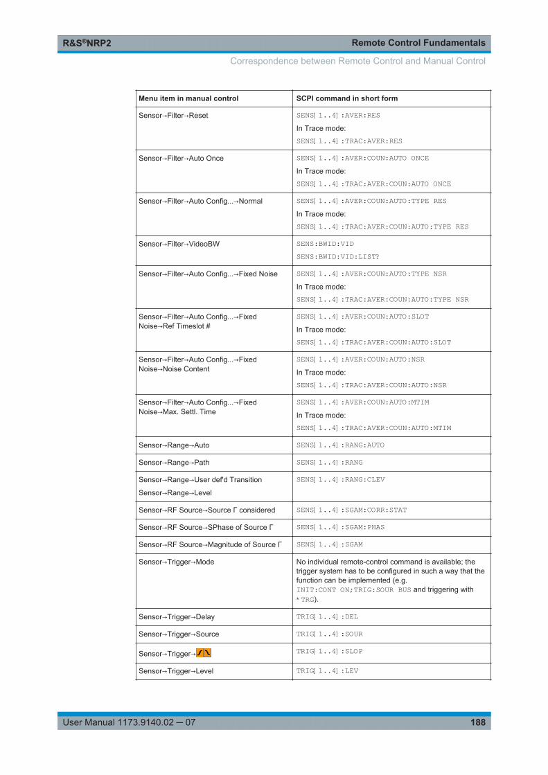
Remote Control FundamentalsR&S®NRP2
188User Manual 1173.9140.02 ─ 07
Menu item in manual control SCPI command in short form
Sensor→Filter→Reset SENS[1..4]:AVER:RESIn Trace mode:
SENS[1..4]:TRAC:AVER:RES
Sensor→Filter→Auto Once SENS[1..4]:AVER:COUN:AUTO ONCEIn Trace mode:
SENS[1..4]:TRAC:AVER:COUN:AUTO ONCE
Sensor→Filter→Auto Config...→Normal SENS[1..4]:AVER:COUN:AUTO:TYPE RESIn Trace mode:
SENS[1..4]:TRAC:AVER:COUN:AUTO:TYPE RES
Sensor→Filter→VideoBW SENS:BWID:VIDSENS:BWID:VID:LIST?
Sensor→Filter→Auto Config...→Fixed Noise SENS[1..4]:AVER:COUN:AUTO:TYPE NSRIn Trace mode:
SENS[1..4]:TRAC:AVER:COUN:AUTO:TYPE NSR
Sensor→Filter→Auto Config...→FixedNoise→Ref Timeslot #
SENS[1..4]:AVER:COUN:AUTO:SLOTIn Trace mode:
SENS[1..4]:TRAC:AVER:COUN:AUTO:SLOT
Sensor→Filter→Auto Config...→FixedNoise→Noise Content
SENS[1..4]:AVER:COUN:AUTO:NSRIn Trace mode:
SENS[1..4]:TRAC:AVER:COUN:AUTO:NSR
Sensor→Filter→Auto Config...→FixedNoise→Max. Settl. Time
SENS[1..4]:AVER:COUN:AUTO:MTIMIn Trace mode:
SENS[1..4]:TRAC:AVER:COUN:AUTO:MTIM
Sensor→Range→Auto SENS[1..4]:RANG:AUTO
Sensor→Range→Path SENS[1..4]:RANG
Sensor→Range→User def'd Transition
Sensor→Range→Level
SENS[1..4]:RANG:CLEV
Sensor→RF Source→Source Γ considered SENS[1..4]:SGAM:CORR:STAT
Sensor→RF Source→SPhase of Source Γ SENS[1..4]:SGAM:PHAS
Sensor→RF Source→Magnitude of Source Γ SENS[1..4]:SGAM
Sensor→Trigger→Mode No individual remote-control command is available; thetrigger system has to be configured in such a way that thefunction can be implemented (e.g.INIT:CONT ON;TRIG:SOUR BUS and triggering with*TRG).
Sensor→Trigger→Delay TRIG[1..4]:DEL
Sensor→Trigger→Source TRIG[1..4]:SOUR
Sensor→Trigger→ TRIG[1..4]:SLOP
Sensor→Trigger→Level TRIG[1..4]:LEV
Correspondence between Remote Control and Manual Control
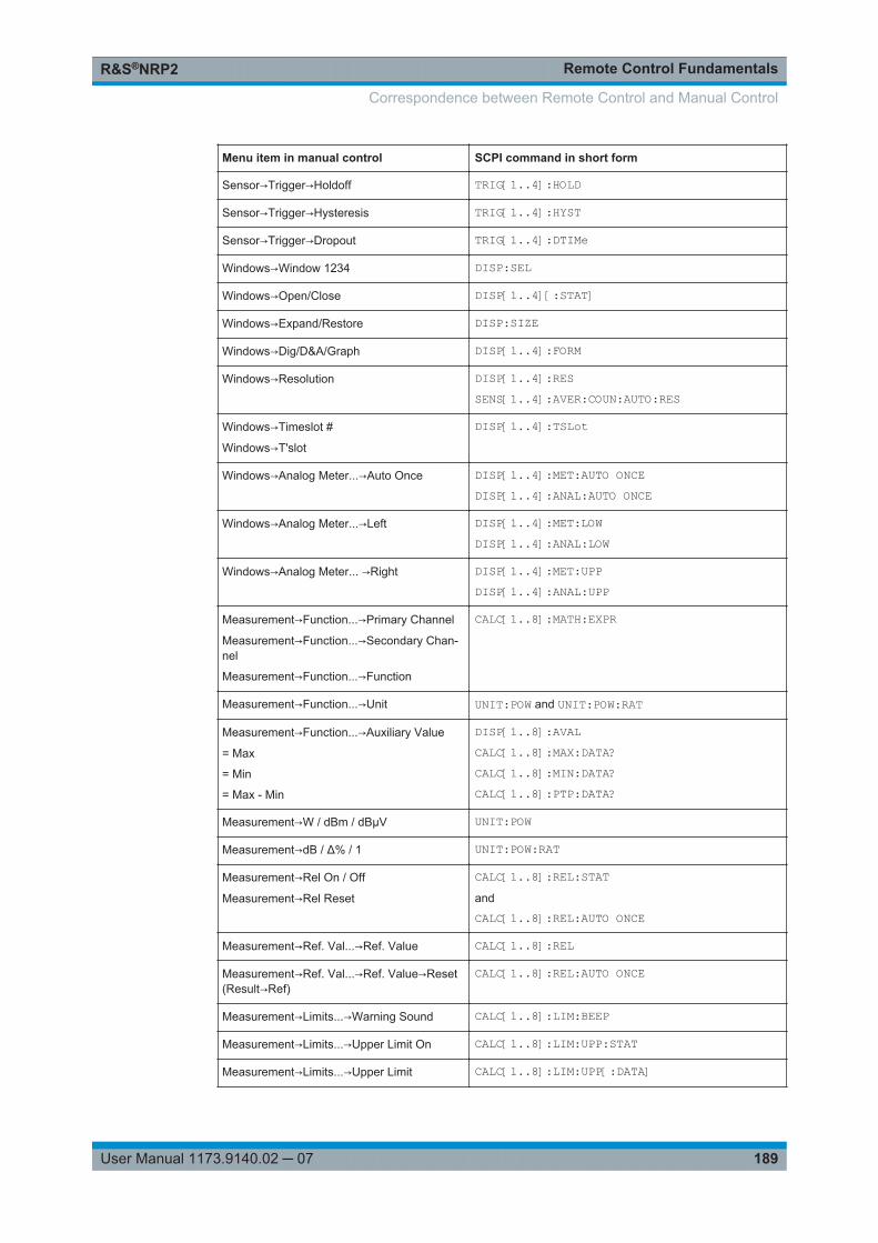
Remote Control FundamentalsR&S®NRP2
189User Manual 1173.9140.02 ─ 07
Menu item in manual control SCPI command in short form
Sensor→Trigger→Holdoff TRIG[1..4]:HOLD
Sensor→Trigger→Hysteresis TRIG[1..4]:HYST
Sensor→Trigger→Dropout TRIG[1..4]:DTIMe
Windows→Window 1234 DISP:SEL
Windows→Open/Close DISP[1..4][:STAT]
Windows→Expand/Restore DISP:SIZE
Windows→Dig/D&A/Graph DISP[1..4]:FORM
Windows→Resolution DISP[1..4]:RESSENS[1..4]:AVER:COUN:AUTO:RES
Windows→Timeslot #
Windows→T'slot
DISP[1..4]:TSLot
Windows→Analog Meter...→Auto Once DISP[1..4]:MET:AUTO ONCEDISP[1..4]:ANAL:AUTO ONCE
Windows→Analog Meter...→Left DISP[1..4]:MET:LOWDISP[1..4]:ANAL:LOW
Windows→Analog Meter... →Right DISP[1..4]:MET:UPPDISP[1..4]:ANAL:UPP
Measurement→Function...→Primary Channel
Measurement→Function...→Secondary Chan-nel
Measurement→Function...→Function
CALC[1..8]:MATH:EXPR
Measurement→Function...→Unit UNIT:POW and UNIT:POW:RAT
Measurement→Function...→Auxiliary Value
= Max
= Min
= Max - Min
DISP[1..8]:AVALCALC[1..8]:MAX:DATA?CALC[1..8]:MIN:DATA?CALC[1..8]:PTP:DATA?
Measurement→W / dBm / dBµV UNIT:POW
Measurement→dB / Δ% / 1 UNIT:POW:RAT
Measurement→Rel On / Off
Measurement→Rel Reset
CALC[1..8]:REL:STATand
CALC[1..8]:REL:AUTO ONCE
Measurement→Ref. Val...→Ref. Value CALC[1..8]:REL
Measurement→Ref. Val...→Ref. Value→Reset(Result→Ref)
CALC[1..8]:REL:AUTO ONCE
Measurement→Limits...→Warning Sound CALC[1..8]:LIM:BEEP
Measurement→Limits...→Upper Limit On CALC[1..8]:LIM:UPP:STAT
Measurement→Limits...→Upper Limit CALC[1..8]:LIM:UPP[:DATA]
Correspondence between Remote Control and Manual Control
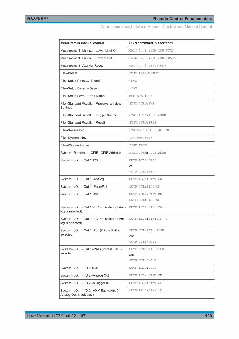
Remote Control FundamentalsR&S®NRP2
190User Manual 1173.9140.02 ─ 07
Menu item in manual control SCPI command in short form
Measurement→Limits...→Lower Limit On CALC[1..8]:LIM:LOW:STAT
Measurement→Limits...→Lower Limit CALC[1..8]:LIM:LOW[:DATA]
Measurement→Aux Val Reset CALC[1..8]:EXTR:RES
File→Preset SYST:PRES or *RST
File→Setup Recall...→Recall *RCL
File→Setup Save...→Save *SAV
File→Setup Save...→Edit Name MEM:STAT:DEF
File→Standard Recall...→Preserve WindowSettings
SYST:STAN:PWS
File→Standard Recall...→Trigger Source SYST:STAN:TRIG:SOUR
File→Standard Recall...→Recall SYST:STAN:PRES
File→Sensor Info... SYSTem:SENS[1..4]:INFO?
File→System Info... SYSTem:INFO?
File→Window Name DISP:NAME
System→Remote... →GPIB→GPIB Address SYST:COMM:GPIB:ADDR
System→I/O... →Out 1 1234 OUTP:REC1:FEEDor
OUTP:TTL:FEED
System→I/O... →Out 1→Analog OUTP:REC1:STAT ON
System→I/O... →Out 1→Pass/Fail OUTP:TTL:STAT ON
System→I/O... →Out 1→Off OUTP:REC1:STAT ONOUTP:TTL:STAT ON
System→I/O... →Out 1→0 V Equivalent (if Ana-log is selected)
OUTP:REC1:LIM:LOW...
System→I/O... →Out 1→3 V Equivalent (if Ana-log is selected)
OUTP:REC1:LIM:UPP...
System→I/O... →Out 1→Fail (if Pass/Fail isselected)
OUTP:TTL:FAIL HIGHand
OUTP:TTL:HVOLT
System→I/O... →Out 1→Pass (if Pass/Fail isselected)
OUTP:TTL:FAIL HIGHand
OUTP:TTL:LVOLT
System→I/O... →I/O 2 1234 OUTP:REC2:FEED
System→I/O... →I/O 2→Analog Out OUTP:REC2:STAT ON
System→I/O... →I/O 2→ATrigger In OUTP:REC2:STAT OFF
System→I/O... →I/O 2→A0 V Equivalent (ifAnalog Out is selected)
OUTP:REC2:LIM:LOW...
Correspondence between Remote Control and Manual Control
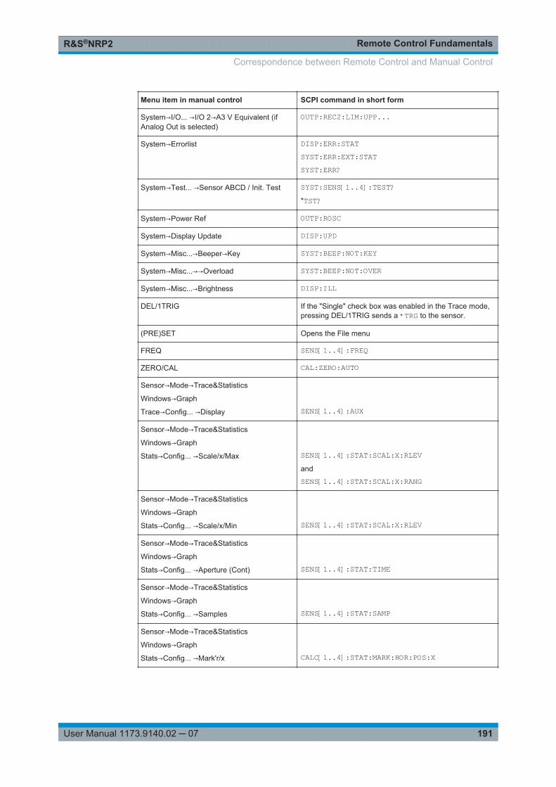
Remote Control FundamentalsR&S®NRP2
191User Manual 1173.9140.02 ─ 07
Menu item in manual control SCPI command in short form
System→I/O... →I/O 2→A3 V Equivalent (ifAnalog Out is selected)
OUTP:REC2:LIM:UPP...
System→Errorlist DISP:ERR:STATSYST:ERR:EXT:STATSYST:ERR?
System→Test... →Sensor ABCD / Init. Test SYST:SENS[1..4]:TEST?*TST?
System→Power Ref OUTP:ROSC
System→Display Update DISP:UPD
System→Misc...→Beeper→Key SYST:BEEP:NOT:KEY
System→Misc...→→Overload SYST:BEEP:NOT:OVER
System→Misc...→Brightness DISP:ILL
DEL/1TRIG If the "Single" check box was enabled in the Trace mode,pressing DEL/1TRIG sends a *TRG to the sensor.
(PRE)SET Opens the File menu
FREQ SENS[1..4]:FREQ
ZERO/CAL CAL:ZERO:AUTO
Sensor→Mode→Trace&Statistics
Windows→Graph
Trace→Config... →Display
SENS[1..4]:AUX
Sensor→Mode→Trace&Statistics
Windows→Graph
Stats→Config... →Scale/x/Max
SENS[1..4]:STAT:SCAL:X:RLEVand
SENS[1..4]:STAT:SCAL:X:RANG
Sensor→Mode→Trace&Statistics
Windows→Graph
Stats→Config... →Scale/x/Min
SENS[1..4]:STAT:SCAL:X:RLEV
Sensor→Mode→Trace&Statistics
Windows→Graph
Stats→Config... →Aperture (Cont)
SENS[1..4]:STAT:TIME
Sensor→Mode→Trace&Statistics
Windows→Graph
Stats→Config... →Samples
SENS[1..4]:STAT:SAMP
Sensor→Mode→Trace&Statistics
Windows→Graph
Stats→Config... →Mark'r/x
CALC[1..4]:STAT:MARK:HOR:POS:X
Correspondence between Remote Control and Manual Control
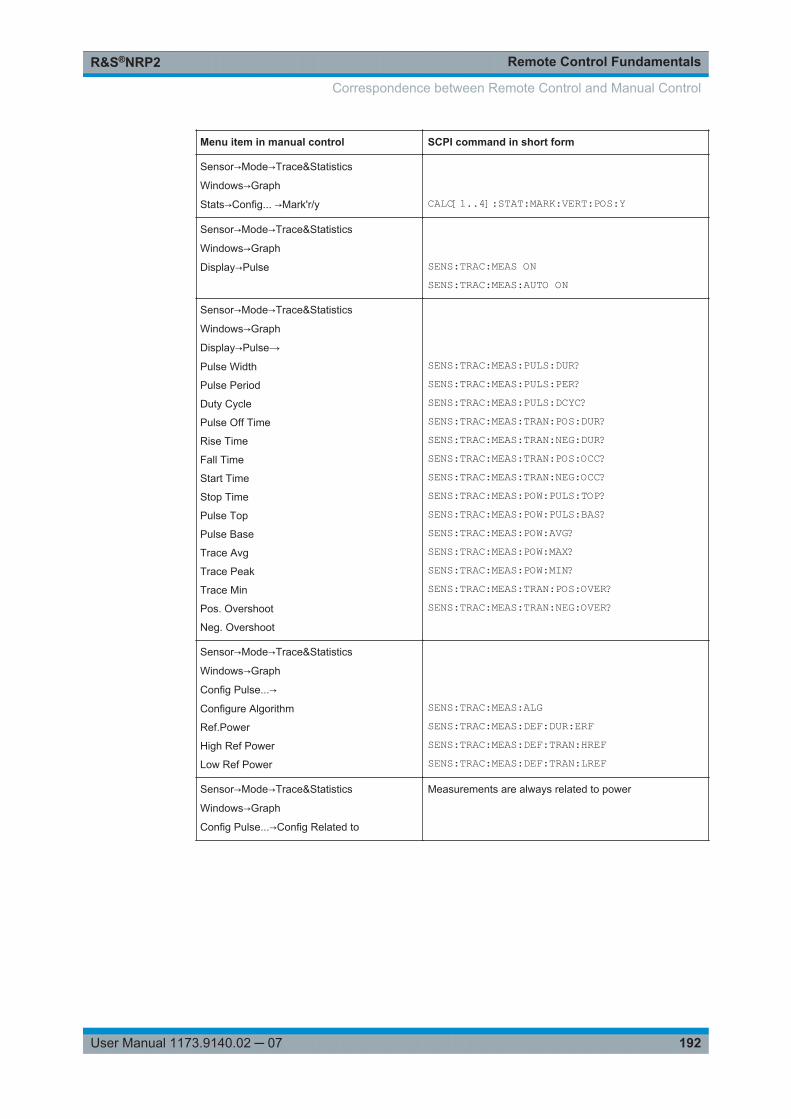
Remote Control FundamentalsR&S®NRP2
192User Manual 1173.9140.02 ─ 07
Menu item in manual control SCPI command in short form
Sensor→Mode→Trace&Statistics
Windows→Graph
Stats→Config... →Mark'r/y
CALC[1..4]:STAT:MARK:VERT:POS:Y
Sensor→Mode→Trace&Statistics
Windows→Graph
Display→Pulse
SENS:TRAC:MEAS ONSENS:TRAC:MEAS:AUTO ON
Sensor→Mode→Trace&Statistics
Windows→Graph
Display→Pulse→
Pulse Width
Pulse Period
Duty Cycle
Pulse Off Time
Rise Time
Fall Time
Start Time
Stop Time
Pulse Top
Pulse Base
Trace Avg
Trace Peak
Trace Min
Pos. Overshoot
Neg. Overshoot
SENS:TRAC:MEAS:PULS:DUR?SENS:TRAC:MEAS:PULS:PER?SENS:TRAC:MEAS:PULS:DCYC?SENS:TRAC:MEAS:TRAN:POS:DUR?SENS:TRAC:MEAS:TRAN:NEG:DUR?SENS:TRAC:MEAS:TRAN:POS:OCC?SENS:TRAC:MEAS:TRAN:NEG:OCC?SENS:TRAC:MEAS:POW:PULS:TOP?SENS:TRAC:MEAS:POW:PULS:BAS?SENS:TRAC:MEAS:POW:AVG?SENS:TRAC:MEAS:POW:MAX?SENS:TRAC:MEAS:POW:MIN?SENS:TRAC:MEAS:TRAN:POS:OVER?SENS:TRAC:MEAS:TRAN:NEG:OVER?
Sensor→Mode→Trace&Statistics
Windows→Graph
Config Pulse...→
Configure Algorithm
Ref.Power
High Ref Power
Low Ref Power
SENS:TRAC:MEAS:ALGSENS:TRAC:MEAS:DEF:DUR:ERFSENS:TRAC:MEAS:DEF:TRAN:HREFSENS:TRAC:MEAS:DEF:TRAN:LREF
Sensor→Mode→Trace&Statistics
Windows→Graph
Config Pulse...→Config Related to
Measurements are always related to power
Correspondence between Remote Control and Manual Control
Remote Control - CommandsR&S®NRP2
193User Manual 1173.9140.02 ─ 07
6 Remote Control - Commands
6.1 Notation
In the following sections, all commands implemented in the device are listed accordingto the command system and then described in detail. For the most part, the notationused complies with SCPI specifications. The commands are separated in high-leveland low-level commands, where the high-level commands combine several low-levelcommands in one command.
Numeric suffixes <n>
If a command can be applied to multiple instances of an object, e.g. specific sensors,the required instances can be specified by a suffix added to the command. Numericsuffixes are indicated by angular brackets (<1...4>, <n>, <i>) and are replaced by a sin-gle value in the command. Entries without a suffix are interpreted as having the suffix1.
Optional keywords [ ]
Some command systems permit certain keywords to be inserted into the header oromitted. These keywords are marked by square brackets in the description. The instru-ment must recognize the long command to comply with the SCPI standard. Some com-mands are considerably shortened by these optional mnemonics.
Therefore, not only is there a short and a long form for the commands (distinguishedhere by lowercase and uppercase letters) but also a short form which is created byomitting optional keywords.
Example: Command [SENSe<[1]..4>]:CORRection:GAIN2[:INPut][:MAGNitude] 1can be written as:SENSe1:CORRection:GAIN2:INPut:MAGNitude 1SENSe1:CORRection:GAIN2:INPut 1SENSe1:CORRection:GAIN2 1SENSe:CORRection:GAIN2 1CORRection:GAIN2 1
Parameters
Parameters must be separated from the header by a "white space". If several parame-ters are specified in a command, they are separated by a comma (,). For a descriptionof the parameter types, refer to chapter 5.7.5, "Parameters", on page 180.
Notation
Remote Control - CommandsR&S®NRP2
194User Manual 1173.9140.02 ─ 07
Example: Definition: OUTPut:AUDiobits <audiobits>Command: OUTP:AUD 24
Special characters | and { }
| A vertical bar in parameter definitions indicates alternative possibilities in the sense of"or". The effect of the command differs, depending on which parameter is used.
Example:
Definition: INITiate:CONTinuous ON | OFFCommand INITiate:CONTinuous ON starts the measurements
Command INITiate:CONTinuous OFF stops the measurements
{ } Parameters in braces may be included in the command once, several times or not at all.
6.1.1 Parameter Types
<NR1> Stands for integers with sign.Examples:● 1● -33● 32767
<NRf> Stands for floating point numbers that can also be written in exponential notation.Examples:● 1● 1.0● -21.2345553e-6
<int_value> Is an abbreviation for <NR1>|MINimum|MAXimum|DEFault.
<float_value> Is an abbreviation for <NRf>|MINimum|MAXimum|DEFault.
<boolean> Stands for ON|OFF|0|1, where ON and 1 are identical in meaning as are OFF and 0.
<string> Stands for character strings that have to be within single or double quotes.Examples:● 'free text'● "Sirius"
<block_data> Stands for block data (chapter 5.7.5, "Parameters", on page 180 ).
<non-deci-mal_numeric>
Is a non-decimal value in one of the following representations:● binary (e. g. #b0111010101001110 or #B0111010101001110)● hexadecimal (e.g. #h754e or #H754E)● octal (e.g. #q72516 or #Q75216)
6.2 Common Commands to IEEE 488.2
The common commands are taken from the IEEE 488.2 (IEC 625–2) standard. Somecommands have the same effect on different devices. The headers of these com-mands consist of an asterisk "*" followed by three letters. Many common commands
Common Commands to IEEE 488.2
Remote Control - CommandsR&S®NRP2
195User Manual 1173.9140.02 ─ 07
refer to the status reporting system which is described in detail in chapter 6.13, "STA-Tus", on page 296.
Commands available in the R&S NRP2
*CLS.............................................................................................................................195*ESE.............................................................................................................................195*ESR?...........................................................................................................................196*IDN?............................................................................................................................196*IST?............................................................................................................................ 196*OPC............................................................................................................................196*OPT?...........................................................................................................................197*PRE............................................................................................................................ 197*PSC............................................................................................................................ 197*RCL.............................................................................................................................198*RST.............................................................................................................................198*SAV ............................................................................................................................204*SRE............................................................................................................................ 204*STB?...........................................................................................................................205*TRG............................................................................................................................ 205*TST?........................................................................................................................... 205*WAI.............................................................................................................................205
*CLS
CLear Status resets the
● status byte (STB)● standard event register (ESR)● EVENt part of the QUEStionable and the OPERation register● Error / event queue
The command does not alter the ENABle and TRANsition parts of the registers.
Usage: Event
*ESE <value>
Setting command: *ESEEvent Status Enable sets the event status enable register to the specified value.
Query: *ESE?The query form *ESE? returns the contents of the event status enable register in deci-mal form.
Parameters:<Value> 0 to 255
Common Commands to IEEE 488.2
Remote Control - CommandsR&S®NRP2
196User Manual 1173.9140.02 ─ 07
*ESR? <value>
Event Status Read returns the contents of the event status register in decimal form (0to 255) and subsequently sets the register to zero.
Parameters:<Value> 0 to 255
Usage: Query only
*IDN?
IDeNtification queries the instrument identification.
Note: The return string can be customized using SYSTem:IDN andSYSTem:IDN:AUTO commands
Example: Return valuesRohde&Schwarz, NRP2, 10001, 07.03The strings have the following meanuing:Rohde&Schwarz = manufacturerNRP2 = instrument type10001 = serial number07.03 = firmware version
Usage: Query only
*IST? <status_bit>
Individual STatus query returns the current value of the IST flag in decimal form. TheIST flag is the status bit which is sent during a parallel poll (chapter 6.13.6, "IST Flagand Parallel Poll Enable Register (PPE)", on page 305
Parameters:<StatusBit> 0 | 1
Usage: Query only
*OPC
Setting Command : *OPCOPeration Complete sets bit 0 in the event status register after all preceding com-mands have been executed. This bit can be used to initiate a service request. *OPCmust be sent at the end of a program message.
Query: *OPC?OPperation Complete query returns a 1 when all previous commands have been pro-cessed. It is important that the timeout set on the IEC/IEEE bus is sufficiently long.
Common Commands to IEEE 488.2
Remote Control - CommandsR&S®NRP2
197User Manual 1173.9140.02 ─ 07
Since *OPC? waits until all previous commands are executed, "1" is returned in allcases. *OPC? basically functions like the *WAI command, but **WAI does not return aresponse. *OPC? is preferred to *WAI because with *OPC?, the execution of com-mands can be queried from a controller program before new commands are sent. Thisavoids an overflow of the input queue when too many commands are sent that cannotbe executed.
Unlike *WAI, *OPC? must be sent at the end of a program message.
*OPT?
OPTion identification query returns a list of the options installed. The options are sepa-rated from each other by means of commas.
Option Response string
R&S NRP-B1 "NRP-B1: Test generator installed"
R&S NRP-B2 "NRP-B2: Second channel interface installed"
R&S NRP-B5 "NRP-B5: Four channel interface installed"
R&S NRP-B6 "NRP-B6: Sensor A/B rear socket"
R&S NRP-B7 "NRP-B7: Test generator installed"
Example: *OPT?Device response:"NRP-B1: Test Generator installed","NRP-B2:Second Channel Interface installed","NRP-B5:Four Channel Interface installed"
Usage: Query only
*PRE <value>
Setting command: *PREParallel poll Register Enable sets the parallel poll enable register to the specified value.
Query: *PRE?The query form *PRE? returns the contents of the parallel poll enable register in deci-mal form.
Parameters:<Value> 0 to 255
*PSC <function>
Setting command: *PSCPower on Status Clear determines whether the contents of the ENABle registers arepreserved or reset during power-up.
Common Commands to IEEE 488.2
Remote Control - CommandsR&S®NRP2
198User Manual 1173.9140.02 ─ 07
Query: *PSC?The query form *PSC? reads out the contents of the power-on-status-clear flag. Theresponse can be 0 or 1.
Parameters:<Function> 0 | 1
0Causes the contents of the status registers to be preserved.Thus a service request can be generated when switching on theinstrument, if the status registers ESE and SRE are suitably con-figured.1Resets the registers.
*RCL <value>
ReCaLl calls the device state which has been stored with the *SAV command underthe specified number. The effect of *RCL 0 to 19 is the same as if one of the setups 0to 19 had been selected in manual control. *RCL 0 resets the device to the defaultstate.
Parameters:<Value> 1 to 19
Available recall numbers for device setups.
Usage: Event
*RST
ReSeT sets the instrument to a defined default status. The command essentially corre-sponds to command SYSTem:PRESet and to pressing (PRE)SET.
The following table documents the difference. SYSTem:PRESet acts like the frontpanelkey (PRE)SET.
Table 6-1: Difference between commands *RST und SYSTem:PRESet
INITiate:CONTinuous SENSe:AVERage:TCONtrol
*RST OFF REPeat
SYSTem:PRESet ON MOVing
The following table lists all preset values
Common Commands to IEEE 488.2
Remote Control - CommandsR&S®NRP2
199User Manual 1173.9140.02 ─ 07
Table 6-2: Preset values
Command Preset and *RST value Remark
CALC<[1]..8>:FEED[1..2] "POW:AVER" The calculate block processesaverage power values ("Aver-age").
CALC<[1]..8>:LIM:BEEP OFF No audible signal in case of limitviolations.
CALC<[1]..8>:LIM:CLE:AUTO OFF No automatic reset of the limitmonitoring function when a mea-surement is started.
CALC<[1]..8>:LIM:FAIL? 0 Limit violation.
CALC<[1]..8>:LIM:FCO? 0 Number of limit violations is reset.
CALC<[1]..8>:LIM:UPP:DATA 0 W or 0 DB Upper limit value for measure-ments.
CALC<[1]..8>:LIM:UPP:STAT OFF No monitoring function for upperlimit value.
CALC<[1]..8>:LIM:LOW:DATA 0 W or 0 DB Lower limit value for measure-ments.
CALC<[1]..8>:LIM:LOW:STAT OFF No monitoring function for lowerlimit value.
CALC<[1]..8>:MATH For command descriptionsee page 231(
The calculate block returns themeasured value of the sensorassigned to the primary channel.
CALC<[1]..8>:REL 0 DBM or 0 DB -
CALC<[1]..8>:REL:POW 0 DBM -
CALC<[1]..8>:REL:RAT 0 DB -
CALC<[1]..8>:REL:STAT OFF Measurements are not convertedinto a reference value.
DISP:ILL - Display lighting remainsunchanged.
DISP:MESS OFF Do not display messages.
DISP:MESS:TEXT - No change.
DISP:MESS:TYPE MESS Messages cannot be confirmedmanually.
DISP:SEL 1 First window selected.
DISP:SIZE NORM Automatic window sizes.
DISP<[1]..4> ON | OFF A window is opened automaticallyfor each connected sensor.
DISP<[1]..4>:AVAL NONE No additional information on mea-sured values displayed.
DISP<[1]..4>:FORM DIG Digital result display.
Common Commands to IEEE 488.2
Remote Control - CommandsR&S®NRP2
200User Manual 1173.9140.02 ─ 07
Command Preset and *RST value Remark
DISP<[1]..4>:MET:LOW -90 DBM-120 DB
Lower limit value for analog resultdisplay.
DISP<[1]..4>:MET:UPP 70 DBM60 DB
Upper limit value for analog resultdisplay.
DISP<[1]..4>:NAME "" Text to be displayed in result win-dow.
DISP<[1]..4>:RES 0.01 Measurement accuracy and dis-play accuracy.
DISP:SEL 1 Selection of first result window.
DISP:SIZE NORM Automatic window sizes.
DISP<[1]..4> ON | OFF A window will automatically beopened for each sensor.
DISP<[1]..4>:TRAC:LOW -120 DBM Lower limit of power axis in Tracemode
DISP<[1]..4>:TRAC:UPP 30 DBM Upper limit of power axis in Tracemode
DISP<[1]..4>:TSL 1 First timeslot
DISP<[1]..4>:UPD NORM Frequent display updates.
FORM ASC Measured data in ASCII format.
FORM:BORD NORM "Big-Endian" byte sequence ofmeasured data, if FORMat REALis selected.
INIT[1..4|:ALL]:CONT ONOFF
PRES and SYSTem:PRESet.
*RST
INIT[1..4|:ALL]:DIS OFF
MEM:… - The settings in the MEMory com-mand system will not be affected.
OUTP:REC1:FEED "CALC1" Analog outputs are fed by the firstcalculate block.
OUTP:REC2:FEED "CALC2" Analog outputs are fed by the sec-ond calculate block.
OUTP:REC[1..2]:LIM:LOW -20 DBM or
0 DB0 V equivalent at analog output.
OUTP:REC[1..2]:LIM:UPP 20 DBM or
10 DB3 V equivalent at analog output.
OUTP:REC1:STAT ON Analog output active.
OUTP:REC2:STAT OFF Trigger input active.
OUTP:ROSC OFF Test generator is switched off.
Common Commands to IEEE 488.2

Remote Control - CommandsR&S®NRP2
201User Manual 1173.9140.02 ─ 07
Command Preset and *RST value Remark
OUTP:TTL:ACT LOW OUTPut:TTL:LVOLtage isapplied to the TTL output if a limitis violated.
OUTP:TTL:FAIL HIGH OUTPut:TTL:HVOLtage isapplied to the TTL output if a limitis violated.
OUTP:TTL:FEED "CALC1:LIM" The TTL output is fed by the limitmonitoring function of calculateblock 1.
OUTP:TTL:HVOLT 3.3 V High voltage at TTL output
OUTP:TTL:LVOLT 0.0 V Low voltage at TTL output
SENS<[1]..4>:AC:RANG 1 | 2 | 3 Depending on sensor.
SENS<[1]..4>:AC:RANG:AUT ON | OFF Depending on sensor.
SENS<[1]..4>:AC:RANG:CLEV <NRf> Depending on sensor.
SENS<[1]..4>:APER <NRf> Depending on sensor.
SENS<[1]..4>:AUXiliary NONE | MINM Depending on sensor.
SENS<[1]..4>:AVER ON | OFF Depending on sensor.
SENS<[1]..4>:AVER:COUN <NR1> Depending on sensor.
SENS<[1]..4>:AVER:COUN:AUTO ON | OFF Depending on sensor.
SENS<[1]..4>:AVER:COUN:AUTO:MTIMe
<NRf> Depending on sensor.
SENS<[1]..4>:AVER:COUN:AUTO:RES
<NRf> Depending on sensor.
SENS<[1]..4>:AVER:COUN:AUTO:SLOT
<NR1> Depending on sensor.
SENS<[1]..4>:AVER:COUN:AUTO:NSR
<NRf> Depending on sensor.
SENS<[1]..4>:AVER:COUN:AUTO:TYPE
RES | NSR Depending on sensor.
SENS<[1]..4>:AVER:TCON MOVREP
PRES and SYSTem:PRESet.
*RST
SENS<[1]..4>:BAND:VIDSENS<[1]..4>:BWID:VID
<string> Depending on sensor.
SENS<[1]..4>:BUFF:SIZe <NR1> Depending on sensor.
SENS<[1]..4>:BUFF:STAT ON | OFF Depending on sensor.
SENS<[1]..4>:BURS:CHOP ON | OFF Depending on sensor.
SENS<[1]..4>:BURS:DTOL <NRf> Depending on sensor.
SENS<[1]..4>:CHOP ON | OFF Depending on sensor.
SENS<[1]..4>:CORR:DCYC <NRf> Depending on sensor.
Common Commands to IEEE 488.2
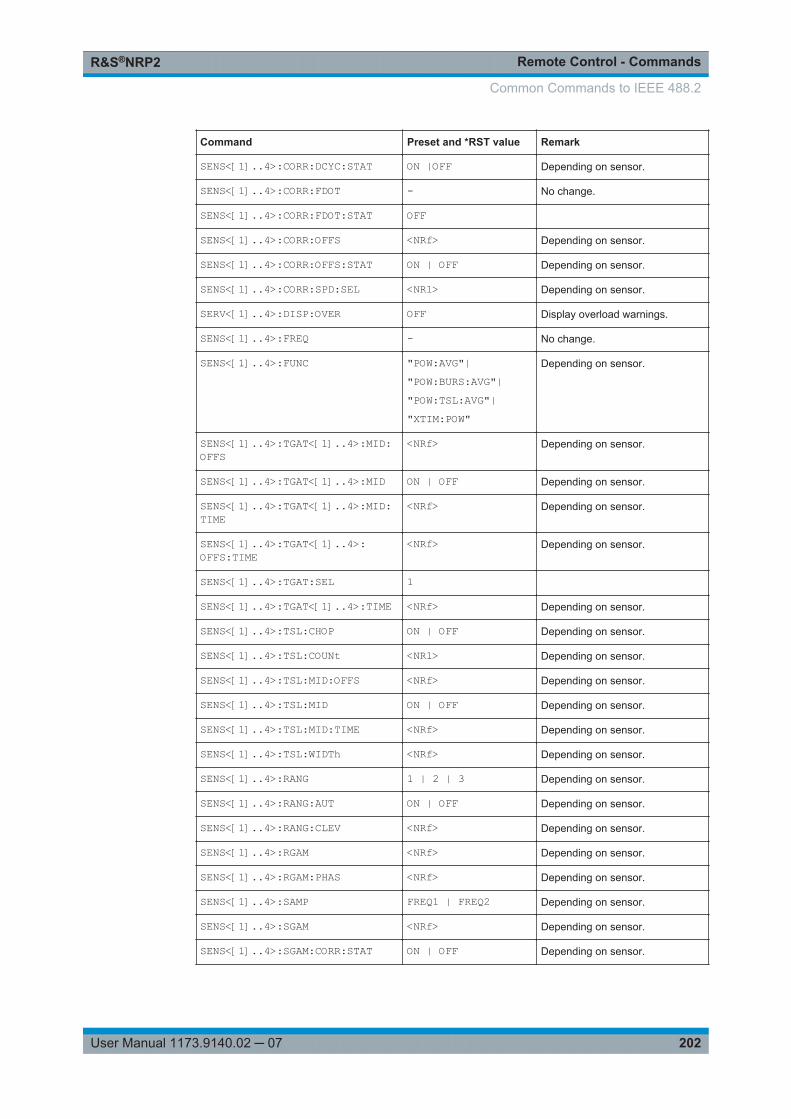
Remote Control - CommandsR&S®NRP2
202User Manual 1173.9140.02 ─ 07
Command Preset and *RST value Remark
SENS<[1]..4>:CORR:DCYC:STAT ON |OFF Depending on sensor.
SENS<[1]..4>:CORR:FDOT - No change.
SENS<[1]..4>:CORR:FDOT:STAT OFF
SENS<[1]..4>:CORR:OFFS <NRf> Depending on sensor.
SENS<[1]..4>:CORR:OFFS:STAT ON | OFF Depending on sensor.
SENS<[1]..4>:CORR:SPD:SEL <NR1> Depending on sensor.
SERV<[1]..4>:DISP:OVER OFF Display overload warnings.
SENS<[1]..4>:FREQ - No change.
SENS<[1]..4>:FUNC "POW:AVG"|"POW:BURS:AVG"|"POW:TSL:AVG"|"XTIM:POW"
Depending on sensor.
SENS<[1]..4>:TGAT<[1]..4>:MID:OFFS
<NRf> Depending on sensor.
SENS<[1]..4>:TGAT<[1]..4>:MID ON | OFF Depending on sensor.
SENS<[1]..4>:TGAT<[1]..4>:MID:TIME
<NRf> Depending on sensor.
SENS<[1]..4>:TGAT<[1]..4>:OFFS:TIME
<NRf> Depending on sensor.
SENS<[1]..4>:TGAT:SEL 1
SENS<[1]..4>:TGAT<[1]..4>:TIME <NRf> Depending on sensor.
SENS<[1]..4>:TSL:CHOP ON | OFF Depending on sensor.
SENS<[1]..4>:TSL:COUNt <NR1> Depending on sensor.
SENS<[1]..4>:TSL:MID:OFFS <NRf> Depending on sensor.
SENS<[1]..4>:TSL:MID ON | OFF Depending on sensor.
SENS<[1]..4>:TSL:MID:TIME <NRf> Depending on sensor.
SENS<[1]..4>:TSL:WIDTh <NRf> Depending on sensor.
SENS<[1]..4>:RANG 1 | 2 | 3 Depending on sensor.
SENS<[1]..4>:RANG:AUT ON | OFF Depending on sensor.
SENS<[1]..4>:RANG:CLEV <NRf> Depending on sensor.
SENS<[1]..4>:RGAM <NRf> Depending on sensor.
SENS<[1]..4>:RGAM:PHAS <NRf> Depending on sensor.
SENS<[1]..4>:SAMP FREQ1 | FREQ2 Depending on sensor.
SENS<[1]..4>:SGAM <NRf> Depending on sensor.
SENS<[1]..4>:SGAM:CORR:STAT ON | OFF Depending on sensor.
Common Commands to IEEE 488.2
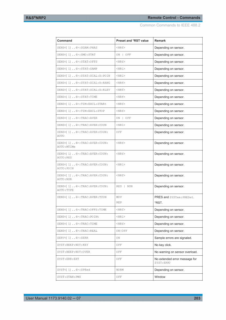
Remote Control - CommandsR&S®NRP2
203User Manual 1173.9140.02 ─ 07
Command Preset and *RST value Remark
SENS<[1]..4>:SGAM:PHAS <NRf> Depending on sensor.
SENS<[1]..4>:SMO:STAT ON | OFF Depending on sensor.
SENS<[1]..4>:STAT:OFFS <NRf> Depending on sensor.
SENS<[1]..4>:STAT:SAMP <NR1> Depending on sensor.
SENS<[1]..4>:STAT:SCAL:X:POIN <NR1> Depending on sensor.
SENS<[1]..4>:STAT:SCAL:X:RANG <NRf> Depending on sensor.
SENS<[1]..4>:STAT:SCAL:X:RLEV <NRf> Depending on sensor.
SENS<[1]..4>:STAT:TIME <NRf> Depending on sensor.
SENS<[1]..4>:TIM:EXCL:STARt <NRf> Depending on sensor.
SENS<[1]..4>:TIM:EXCL:STOP <NRf> Depending on sensor.
SENS<[1]..4>:TRAC:AVER ON | OFF Depending on sensor.
SENS<[1]..4>:TRAC:AVER:COUN <NR1> Depending on sensor.
SENS<[1]..4>:TRAC:AVER:COUN:AUTO
OFF Depending on sensor.
SENS<[1]..4>:TRAC:AVER:COUN:AUTO:MTIMe
<NRf> Depending on sensor.
SENS<[1]..4>:TRAC:AVER:COUN:AUTO:RES
<NRf> Depending on sensor.
SENS<[1]..4>:TRAC:AVER:COUN:AUTO:POIN
<NR1> Depending on sensor.
SENS<[1]..4>:TRAC:AVER:COUN:AUTO:NSR
<NRf> Depending on sensor.
SENS<[1]..4>:TRAC:AVER:COUN:AUTO:TYPE
RES | NSR Depending on sensor.
SENS<[1]..4>:TRAC:AVER:TCON MOVREP
PRES and SYSTem:PRESet.
*RST.
SENS<[1]..4>:TRAC:OFFS:TIME <NRf> Depending on sensor.
SENS<[1]..4>:TRAC:POINt <NR1> Depending on sensor.
SENS<[1]..4>:TRAC:TIME <NRf> Depending on sensor.
SENS<[1]..4>:TRAC:REAL ON|OFF Depending on sensor.
SERV<[1]..4>:SERR ON Sample errors are signaled.
SYST:BEEP:NOT:KEY OFF No key click.
SYST:BEEP:NOT:OVER OFF No warning on sensor overload.
SYST:ERR:EXT OFF No extended error message forSYST:ERR?
SYST<[1]..4>:SPEed NORM Depending on sensor.
SYST:STAN:PWS OFF Window
Common Commands to IEEE 488.2
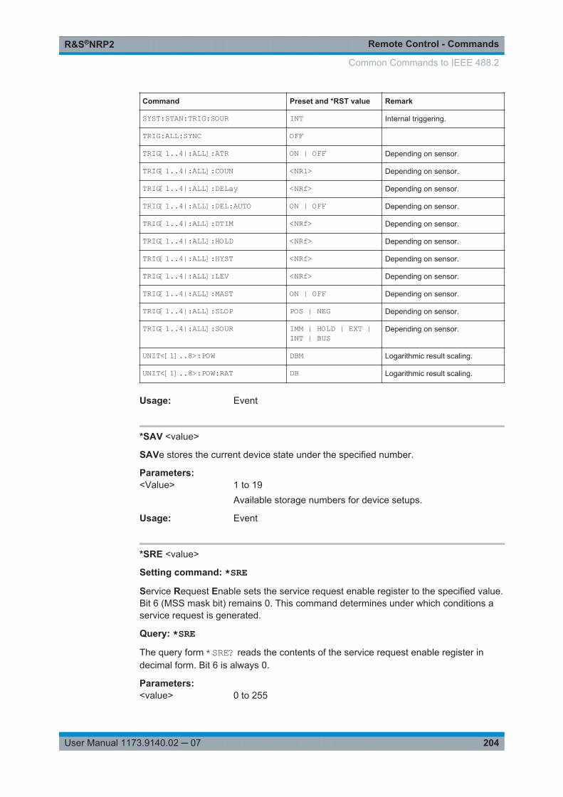
Remote Control - CommandsR&S®NRP2
204User Manual 1173.9140.02 ─ 07
Command Preset and *RST value Remark
SYST:STAN:TRIG:SOUR INT Internal triggering.
TRIG:ALL:SYNC OFF
TRIG[1..4|:ALL]:ATR ON | OFF Depending on sensor.
TRIG[1..4|:ALL]:COUN <NR1> Depending on sensor.
TRIG[1..4|:ALL]:DELay <NRf> Depending on sensor.
TRIG[1..4|:ALL]:DEL:AUTO ON | OFF Depending on sensor.
TRIG[1..4|:ALL]:DTIM <NRf> Depending on sensor.
TRIG[1..4|:ALL]:HOLD <NRf> Depending on sensor.
TRIG[1..4|:ALL]:HYST <NRf> Depending on sensor.
TRIG[1..4|:ALL]:LEV <NRf> Depending on sensor.
TRIG[1..4|:ALL]:MAST ON | OFF Depending on sensor.
TRIG[1..4|:ALL]:SLOP POS | NEG Depending on sensor.
TRIG[1..4|:ALL]:SOUR IMM | HOLD | EXT |INT | BUS
Depending on sensor.
UNIT<[1]..8>:POW DBM Logarithmic result scaling.
UNIT<[1]..8>:POW:RAT DB Logarithmic result scaling.
Usage: Event
*SAV <value>
SAVe stores the current device state under the specified number.
Parameters:<Value> 1 to 19
Available storage numbers for device setups.
Usage: Event
*SRE <value>
Setting command: *SREService Request Enable sets the service request enable register to the specified value.Bit 6 (MSS mask bit) remains 0. This command determines under which conditions aservice request is generated.
Query: *SREThe query form *SRE? reads the contents of the service request enable register indecimal form. Bit 6 is always 0.
Parameters:<value> 0 to 255
Common Commands to IEEE 488.2
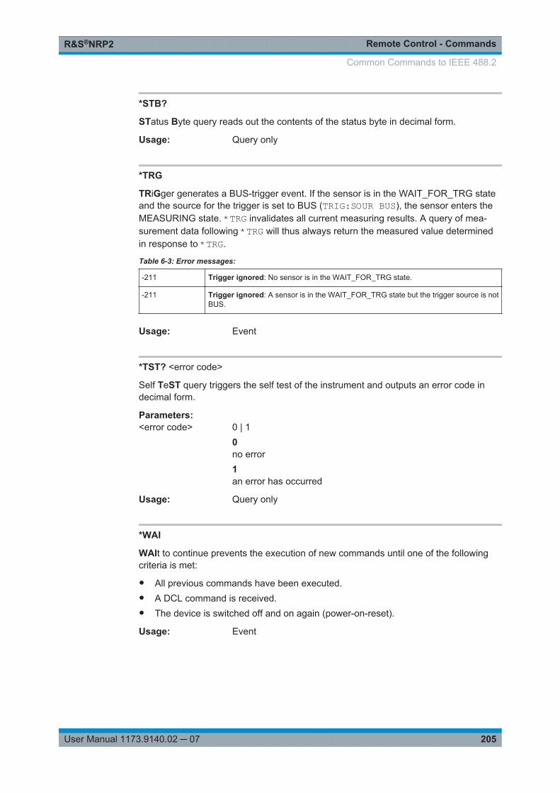
Remote Control - CommandsR&S®NRP2
205User Manual 1173.9140.02 ─ 07
*STB?
STatus Byte query reads out the contents of the status byte in decimal form.
Usage: Query only
*TRG
TRiGger generates a BUS-trigger event. If the sensor is in the WAIT_FOR_TRG stateand the source for the trigger is set to BUS (TRIG:SOUR BUS), the sensor enters theMEASURING state. *TRG invalidates all current measuring results. A query of mea-surement data following *TRG will thus always return the measured value determinedin response to *TRG.
Table 6-3: Error messages:
-211 Trigger ignored: No sensor is in the WAIT_FOR_TRG state.
-211 Trigger ignored: A sensor is in the WAIT_FOR_TRG state but the trigger source is notBUS.
Usage: Event
*TST? <error code>
Self TeST query triggers the self test of the instrument and outputs an error code indecimal form.
Parameters:<error code> 0 | 1
0no error1an error has occurred
Usage: Query only
*WAI
WAIt to continue prevents the execution of new commands until one of the followingcriteria is met:
● All previous commands have been executed.● A DCL command is received.● The device is switched off and on again (power-on-reset).
Usage: Event
Common Commands to IEEE 488.2
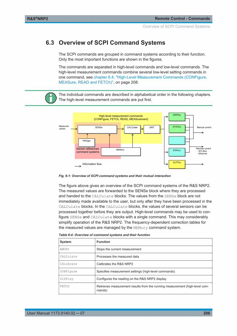
Remote Control - CommandsR&S®NRP2
206User Manual 1173.9140.02 ─ 07
6.3 Overview of SCPI Command Systems
The SCPI commands are grouped in command systems according to their function.Only the most important functions are shown in the figures.
The commands are separated in high-level commands and low-level commands. Thehigh-level measurement commands combine several low-level setting commands inone command, see chapter 6.4, "High-Level Measurement Commands (CONFigure,MEASure, READ and FETCh)", on page 208.
The individual commands are described in alphabetical order in the following chapters.The high-level measurement commands are put first.
TRIGger
SENSe
OUTPut
DISPlay
SYSTem
MEMory
(CONFigure, FETCh, READ, MEASurement) High-level measurement commands
Sensor referencedcommand systems
Measuredvalues Manual control
Remote control- IEC-Bus- Ethernet
Information flow
STATus
UNITCALCulate
Fig. 6-1: Overview of SCPI command systems and their mutual interaction
The figure above gives an overview of the SCPI command systems of the R&S NRP2.The measured values are forwarded to the SENSe block where they are processedand handed to the CALCulate blocks. The values from the SENSe block are notimmediately made available to the user, but only after they have been processed in theCALCulate blocks. In the CALCulate blocks, the values of several sensors can beprocessed together before they are output. High-level commands may be used to con-figure SENSe and CALCulate blocks with a single command. This may considerablysimplify operation of the R&S NRP2. The frequency-dependent correction tables forthe measured values are managed by the MEMory command system.
Table 6-4: Overview of command systems and their function
System Function
ABORt Stops the current measurement
CALCulate Processes the measured data
CALibrate Calibrates the R&S NRP2
CONFigure Specifies measurement settings (high-level commands)
DISPlay Configures the reading on the R&S NRP2 display.
FETCh Retrieves measurement results from the running measurement (high-level com-mands)
Overview of SCPI Command Systems
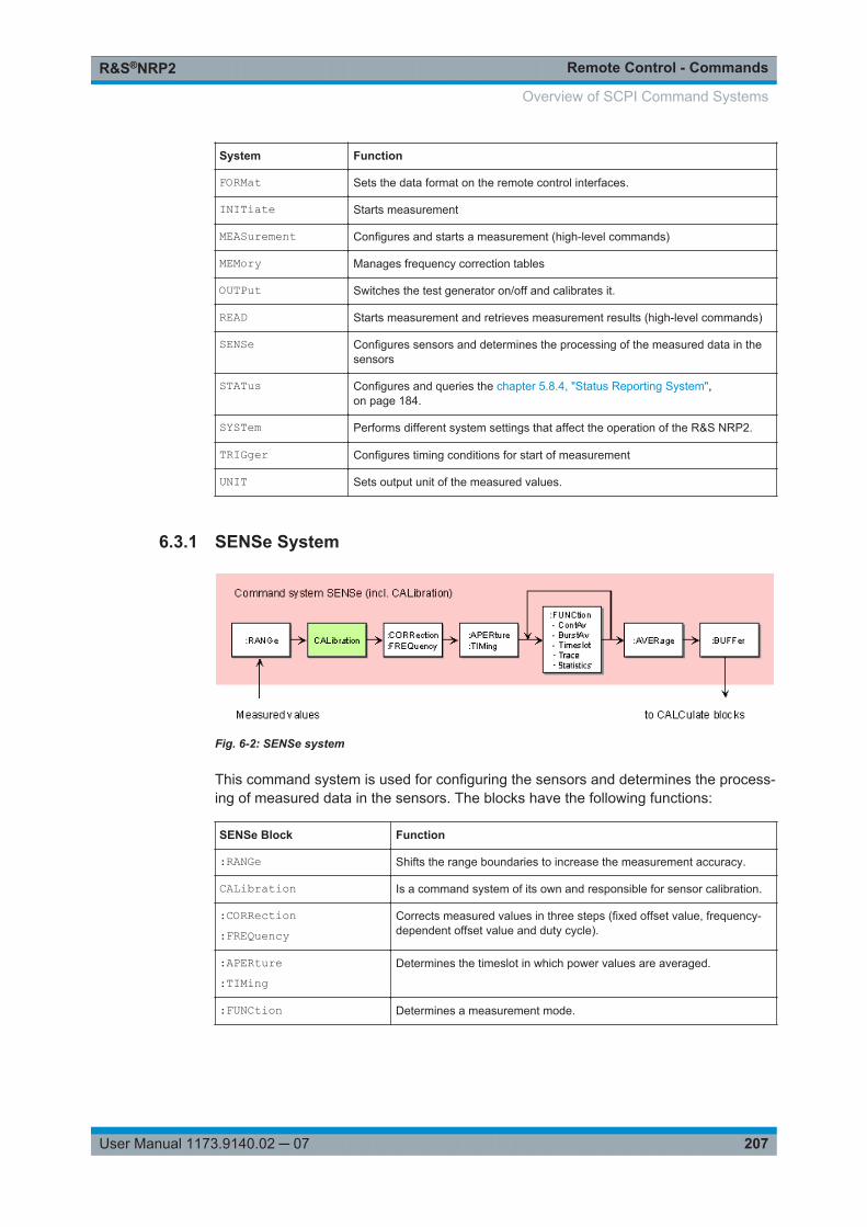
Remote Control - CommandsR&S®NRP2
207User Manual 1173.9140.02 ─ 07
System Function
FORMat Sets the data format on the remote control interfaces.
INITiate Starts measurement
MEASurement Configures and starts a measurement (high-level commands)
MEMory Manages frequency correction tables
OUTPut Switches the test generator on/off and calibrates it.
READ Starts measurement and retrieves measurement results (high-level commands)
SENSe Configures sensors and determines the processing of the measured data in thesensors
STATus Configures and queries the chapter 5.8.4, "Status Reporting System",on page 184.
SYSTem Performs different system settings that affect the operation of the R&S NRP2.
TRIGger Configures timing conditions for start of measurement
UNIT Sets output unit of the measured values.
6.3.1 SENSe System
Fig. 6-2: SENSe system
This command system is used for configuring the sensors and determines the process-ing of measured data in the sensors. The blocks have the following functions:
SENSe Block Function
:RANGe Shifts the range boundaries to increase the measurement accuracy.
CALibration Is a command system of its own and responsible for sensor calibration.
:CORRection:FREQuency
Corrects measured values in three steps (fixed offset value, frequency-dependent offset value and duty cycle).
:APERture:TIMing
Determines the timeslot in which power values are averaged.
:FUNCtion Determines a measurement mode.
Overview of SCPI Command Systems
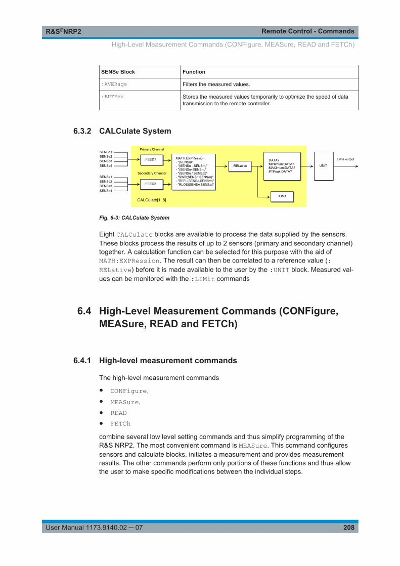
Remote Control - CommandsR&S®NRP2
208User Manual 1173.9140.02 ─ 07
SENSe Block Function
:AVERage Filters the measured values.
:BUFFer Stores the measured values temporarily to optimize the speed of datatransmission to the remote controller.
6.3.2 CALCulate System
:MATH:EXPRession - "(SENSn)" - "(SENSn - SENSm)" - "(SENSn+SENSm)" - "(SENSn / SENSm)" - "SWR(SENSn,SENSm)" - "REFL(SENSn,SENSm)" - "RLOS(SENSn,SENSm)"
:RELative UNIT
:LIMit
:DATA?:MINimum:DATA?:MAXimum:DATA?:PTPeak:DATA?
CALCulate[1..8]
Data output
Primary Channel
Secondary Channel
:FEED1
:FEED2
SENSe1SENSe2SENSe3SENSe4
SENSe1SENSe2SENSe3SENSe4
Fig. 6-3: CALCulate System
Eight CALCulate blocks are available to process the data supplied by the sensors.These blocks process the results of up to 2 sensors (primary and secondary channel)together. A calculation function can be selected for this purpose with the aid ofMATH:EXPRession. The result can then be correlated to a reference value (:RELative) before it is made available to the user by the :UNIT block. Measured val-ues can be monitored with the :LIMit commands
6.4 High-Level Measurement Commands (CONFigure,MEASure, READ and FETCh)
6.4.1 High-level measurement commands
The high-level measurement commands
● CONFigure,● MEASure,● READ● FETChcombine several low level setting commands and thus simplify programming of theR&S NRP2. The most convenient command is MEASure. This command configuressensors and calculate blocks, initiates a measurement and provides measurementresults. The other commands perform only portions of these functions and thus allowthe user to make specific modifications between the individual steps.
High-Level Measurement Commands (CONFigure, MEASure, READ and FETCh)
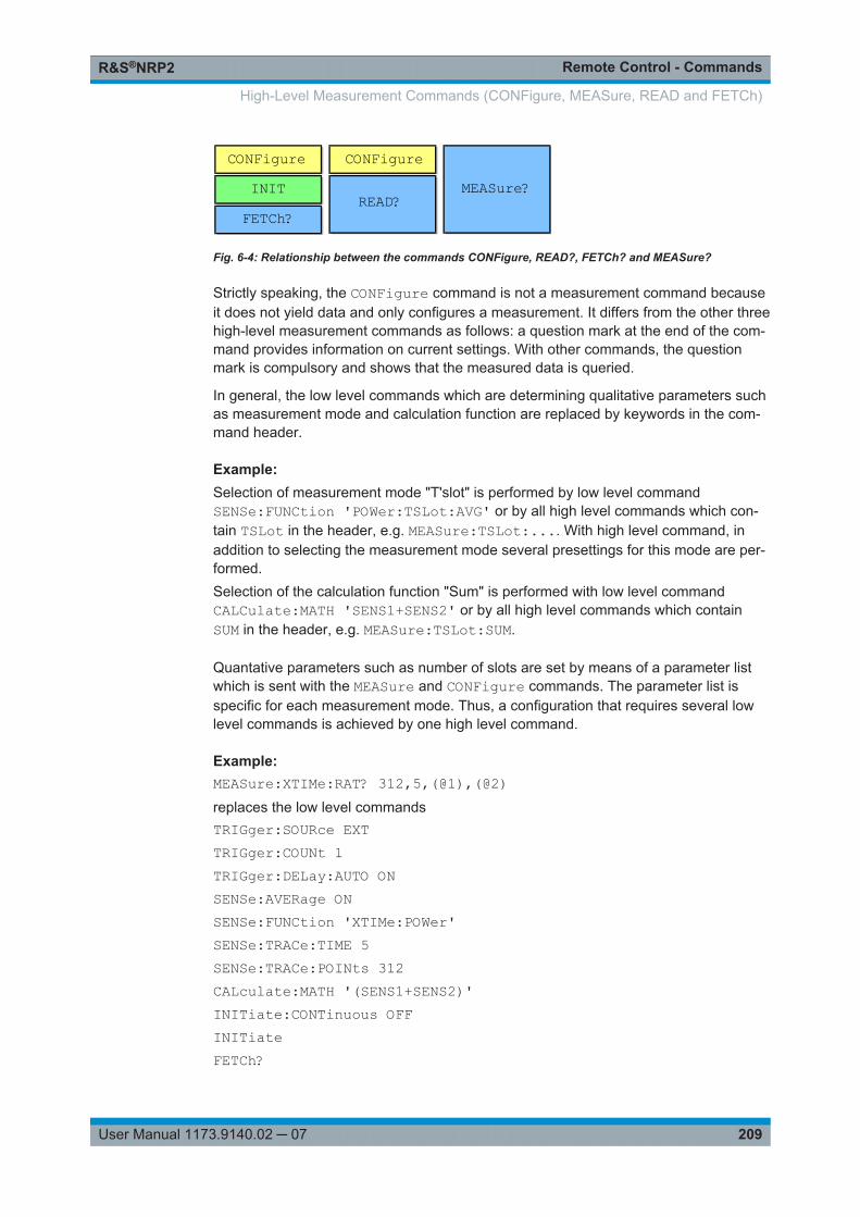
Remote Control - CommandsR&S®NRP2
209User Manual 1173.9140.02 ─ 07
CONFigureINITFETCh?
CONFigure
READ?MEASure?
Fig. 6-4: Relationship between the commands CONFigure, READ?, FETCh? and MEASure?
Strictly speaking, the CONFigure command is not a measurement command becauseit does not yield data and only configures a measurement. It differs from the other threehigh-level measurement commands as follows: a question mark at the end of the com-mand provides information on current settings. With other commands, the questionmark is compulsory and shows that the measured data is queried.
In general, the low level commands which are determining qualitative parameters suchas measurement mode and calculation function are replaced by keywords in the com-mand header.
Example: Selection of measurement mode "T'slot" is performed by low level commandSENSe:FUNCtion 'POWer:TSLot:AVG' or by all high level commands which con-tain TSLot in the header, e.g. MEASure:TSLot:.... With high level command, inaddition to selecting the measurement mode several presettings for this mode are per-formed.Selection of the calculation function "Sum" is performed with low level commandCALCulate:MATH 'SENS1+SENS2' or by all high level commands which containSUM in the header, e.g. MEASure:TSLot:SUM.
Quantative parameters such as number of slots are set by means of a parameter listwhich is sent with the MEASure and CONFigure commands. The parameter list isspecific for each measurement mode. Thus, a configuration that requires several lowlevel commands is achieved by one high level command.
Example: MEASure:XTIMe:RAT? 312,5,(@1),(@2)replaces the low level commandsTRIGger:SOURce EXTTRIGger:COUNt 1TRIGger:DELay:AUTO ONSENSe:AVERage ONSENSe:FUNCtion 'XTIMe:POWer'SENSe:TRACe:TIME 5SENSe:TRACe:POINts 312CALculate:MATH '(SENS1+SENS2)'INITiate:CONTinuous OFFINITiateFETCh?
High-Level Measurement Commands (CONFigure, MEASure, READ and FETCh)
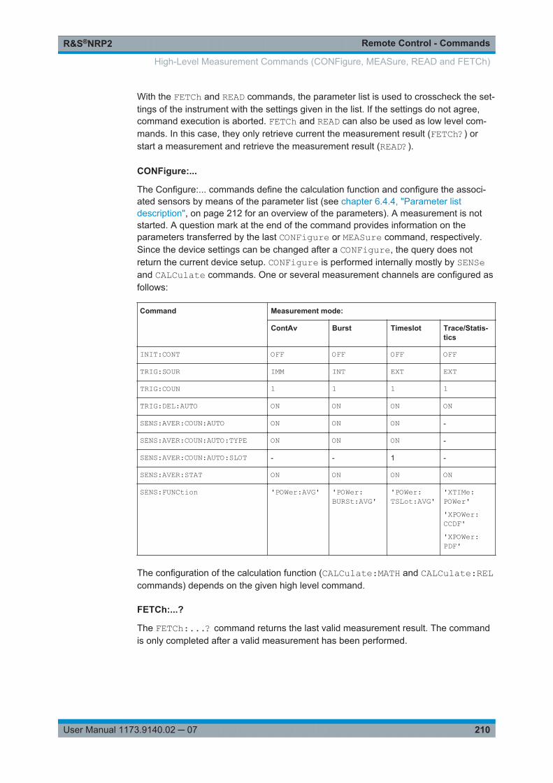
Remote Control - CommandsR&S®NRP2
210User Manual 1173.9140.02 ─ 07
With the FETCh and READ commands, the parameter list is used to crosscheck the set-tings of the instrument with the settings given in the list. If the settings do not agree,command execution is aborted. FETCh and READ can also be used as low level com-mands. In this case, they only retrieve current the measurement result (FETCh?) orstart a measurement and retrieve the measurement result (READ?).
CONFigure:...
The Configure:... commands define the calculation function and configure the associ-ated sensors by means of the parameter list (see chapter 6.4.4, "Parameter listdescription", on page 212 for an overview of the parameters). A measurement is notstarted. A question mark at the end of the command provides information on theparameters transferred by the last CONFigure or MEASure command, respectively.Since the device settings can be changed after a CONFigure, the query does notreturn the current device setup. CONFigure is performed internally mostly by SENSeand CALCulate commands. One or several measurement channels are configured asfollows:
Command Measurement mode:
ContAv Burst Timeslot Trace/Statis-tics
INIT:CONT OFF OFF OFF OFF
TRIG:SOUR IMM INT EXT EXT
TRIG:COUN 1 1 1 1
TRIG:DEL:AUTO ON ON ON ON
SENS:AVER:COUN:AUTO ON ON ON -
SENS:AVER:COUN:AUTO:TYPE ON ON ON -
SENS:AVER:COUN:AUTO:SLOT - - 1 -
SENS:AVER:STAT ON ON ON ON
SENS:FUNCtion 'POWer:AVG' 'POWer:BURSt:AVG'
'POWer:TSLot:AVG'
'XTIMe:POWer''XPOWer:CCDF''XPOWer:PDF'
The configuration of the calculation function (CALCulate:MATH and CALCulate:RELcommands) depends on the given high level command.
FETCh:...?
The FETCh:...? command returns the last valid measurement result. The commandis only completed after a valid measurement has been performed.
High-Level Measurement Commands (CONFigure, MEASure, READ and FETCh)
Remote Control - CommandsR&S®NRP2
211User Manual 1173.9140.02 ─ 07
In compliance with SCPI 1999.0, different results can be queried with FETCh withouthaving to restart a measurement. This is the case if only the keywords for the calcula-tion function (e.g. :RATio:RELative) is changed.
In all other cases, e.g. changing the measurement function, an SCPI error (-221, Set-ting conflict) is returned and the command aborted.
Example: Valid command sequence:FETCh:TSLot:SUM? 577us,8,0,0FETCh:TSLot:SUM:RELative? 577us,8,0,0invalid command sequence:FETCh:BURSt:SUM? 0,0,0FETCh:TSLot:SUM? 577us,8,0,0
READ:...?
The READ:...? command starts a measurement without further configuration andreturns the measurement result. The parameter list is compared to the current settingsbefore the measurement is started. If the list does not agree, an SCPI error (-221, Set-ting conflict) is returned and the command is aborted. Apart from this check, READ cor-responds to the program message INIT:IMM; FETCh[1..8]:...?.
MEASure:...?
The MEASure:...? command combines CONFigure and READ.
Refer to annex chapter A.4, "Programming Measurements", on page 379 for applica-tion examples to the high level measurement commands.
6.4.2 Basic Commands FETCh? and READ?
FETCh?
The command FETCh? without further keywords and parameter list has a specialmeaning. While omitting parameters of the parameter list normally means that defaultvalues are used and checked, the current measured value under FETCh? is suppliedwhen it is valid. If a measured value is not yet available, processing is suspended untila valid result is available.
Usage: Query only
READ?
The READ? command without further keywords and parameter list can be comparedwith FETCh?. READ? starts a measurement and returns a measured value withoutchecking the current settings.
High-Level Measurement Commands (CONFigure, MEASure, READ and FETCh)
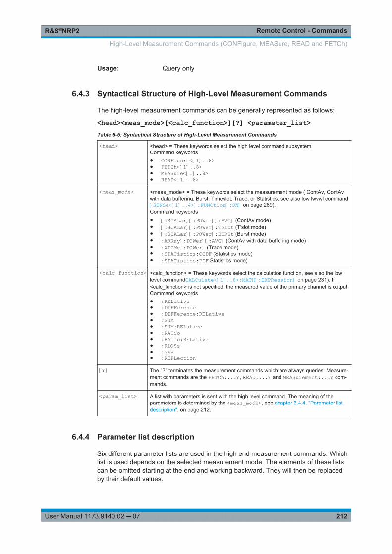
Remote Control - CommandsR&S®NRP2
212User Manual 1173.9140.02 ─ 07
Usage: Query only
6.4.3 Syntactical Structure of High-Level Measurement Commands
The high-level measurement commands can be generally represented as follows:
<head><meas_mode>[<calc_function>][?] <parameter_list>Table 6-5: Syntactical Structure of High-Level Measurement Commands
<head> <head> = These keywords select the high level command subsystem.Command keywords● CONFigure<[1]..8>● FETCh<[1]..8>● MEASure<[1]..8>● READ<[1]..8>
<meas_mode> <meas_mode> = These keywords select the measurement mode ( ContAv, ContAvwith data buffering, Burst, Timeslot, Trace, or Statistics, see also low lwvwl command[SENSe<[1]..4>]:FUNCtion[:ON] on page 269).Command keywords● [:SCALar][:POWer][:AVG] (ContAv mode)● [:SCALar][:POWer]:TSLot (T'slot mode)● [:SCALar][:POWer]:BURSt (Burst mode)● :ARRay[:POWer][:AVG] (ContAv with data buffering mode)● :XTIMe[:POWer] (Trace mode)● :STATistics:CCDF (Statistics mode)● :STATistics:PDF Statistics mode)
<calc_function> <calc_function> = These keywords select the calculation function, see also the lowlevel commandCALCulate<[1]..8>:MATH[:EXPRession] on page 231). If<calc_function> is not specified, the measured value of the primary channel is output.Command keywords● :RELative● :DIFFerence● :DIFFerence:RELative● :SUM● :SUM:RELative● :RATio● :RATio:RELative● :RLOSs● :SWR● :REFLection
[?] The "?" terminates the measurement commands which are always queries. Measure-ment commands are the FETCh:...?, READ:...? and MEASurement:...? com-mands.
<param_list> A list with parameters is sent with the high level command. The meaning of theparameters is determined by the <meas_mode>, see chapter 6.4.4, "Parameter listdescription", on page 212.
6.4.4 Parameter list description
Six different parameter lists are used in the high end measurement commands. Whichlist is used depends on the selected measurement mode. The elements of these listscan be omitted starting at the end and working backward. They will then be replacedby their default values.
High-Level Measurement Commands (CONFigure, MEASure, READ and FETCh)
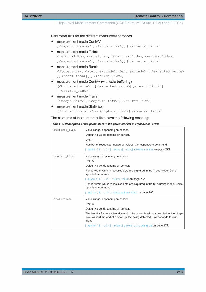
Remote Control - CommandsR&S®NRP2
213User Manual 1173.9140.02 ─ 07
Parameter lists for the different measurement modes● measurement mode ContAV:
[<expected_value> [,<resolution>]] [,<source_list>]● measurement mode T'slot:
<tslot_width>, <no_slots>, <start_exclude>, <end_exclude>,[<expected_value> [,<resolution>]] [,<source_list>]
● measurement mode Burst:<dtolerance>, <start_exclude>, <end_exclude>, [<expected_value>[,<resolution>]] [,<source_list>]
● measurement mode ContAv (with data buffering)(<buffered_size>), [<expected_value>[,<resolution>]][,<source_list>]
● measurement mode Trace:(<scope_size>), <capture_time> [,<source_list>]
● measurement mode Statistics:(<statistics_size>), <capture_time> [,<source_list>]
The elements of the parameter lists have the following meaning:
Table 6-6: Description of the parameters in the parameter list in alphabetical order
<buffered_size> Value range: depending on sensor.
Default value: depending on sensor.
Unit: -
Number of requested measured values. Corresponds to command:
[SENSe<[1]..4>][:POWer][:AVG]:BUFFer:SIZE on page 272.
<capture_time> Value range: depending on sensor.
Unit: S
Default value: depending on sensor.
Period within which measured data are captured in the Trace mode. Corre-sponds to command:
[SENSe<[1]..4>]:TRACe:TIME on page 293.
Period within which measured data are captured in the STATistics mode. Corre-sponds to command:
[SENSe<[1]..4>]:STATistics:TIME on page 283.
<dtolerance> Value range: depending on sensor.
Unit: S
Default value: depending on sensor.
The length of a time interval in which the power level may drop below the triggerlevel without the end of a power pulse being detected. Corresponds to com-mand:
[SENSe<[1]..4>][:POWer]:BURSt:DTOLerance on page 274.
High-Level Measurement Commands (CONFigure, MEASure, READ and FETCh)
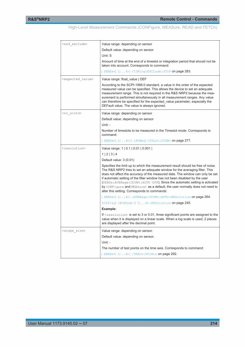
Remote Control - CommandsR&S®NRP2
214User Manual 1173.9140.02 ─ 07
<end_exclude> Value range: depending on sensor
Default value: depending on sensor
Unit: S
Amount of time at the end of a timeslot or integration period that should not betaken into account. Corresponds to command:
[SENSe<[1]..4>]:TIMing:EXCLude:STOP on page 283.
<expected_value> Value range: float_value | DEF
According to the SCPI-1999.0 standard, a value in the order of the expectedmeasured value can be specified. This allows the device to set an adequatemeasurement range. This is not required in the R&S NRP2 because the mea-surement is performed simultaneously in all measurement ranges. Any valuecan therefore be specified for the expected_value parameter, especially theDEFault value. The value is always ignored.
<no_slots> Value range: depending on sensor
Default value: depending on sensor
Unit: -
Number of timeslots to be measured in the Timeslot mode. Corresponds tocommand:
[SENSe<[1]..4>][:POWer]:TSLot:COUNt on page 277.
<resolution> Value range: 1 | 0.1 | 0.01 | 0.001 |
1 | 2 | 3 | 4
Default value: 3 (0.01)
Specifies the limit up to which the measurement result should be free of noise.The R&S NRP2 tries to set an adequate window for the averaging filter. Thisdoes not affect the accuracy of the measured data. The window can only be setif automatic setting of the filter window has not been disabled by the user(SENSe:AVERage:COUNt:AUTO OFF). Since the automatic setting is activatedby CONFigure and MEASure? as a default, the user normally does not need toalter this setting. Corresponds to commands:
[SENSe<[1]..4>]:AVERage:COUNt:AUTO:RESolution on page 264.
DISPlay[:WINDow]<[1]..4>:RESolution on page 245.
Example:
If <resolution> is set to 3 or 0.01, three significant points are assigned to thevalue when it is displayed on a linear scale. When a log scale is used, 2 placesare displayed after the decimal point.
<scope_size> Value range: depending on sensor.
Default value: depending on sensor.
Unit: -
The number of test points on the time axis. Corresponds to command:
[SENSe<[1]..4>]:TRACe:POINts on page 292.
High-Level Measurement Commands (CONFigure, MEASure, READ and FETCh)
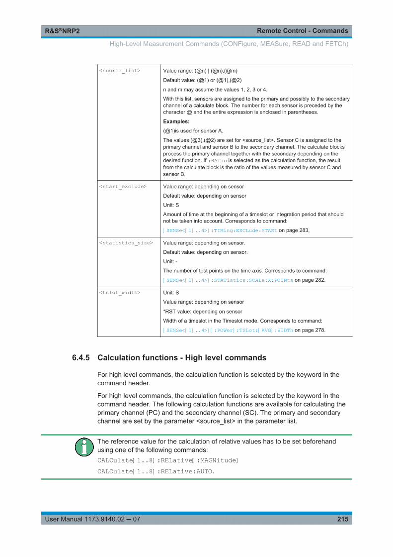
Remote Control - CommandsR&S®NRP2
215User Manual 1173.9140.02 ─ 07
<source_list> Value range: (@n) | (@n),(@m)
Default value: (@1) or (@1),(@2)
n and m may assume the values 1, 2, 3 or 4.
With this list, sensors are assigned to the primary and possibly to the secondarychannel of a calculate block. The number for each sensor is preceded by thecharacter @ and the entire expression is enclosed in parentheses.
Examples:
(@1)is used for sensor A.
The values (@3),(@2) are set for <source_list>. Sensor C is assigned to theprimary channel and sensor B to the secondary channel. The calculate blocksprocess the primary channel together with the secondary depending on thedesired function. If :RATio is selected as the calculation function, the resultfrom the calculate block is the ratio of the values measured by sensor C andsensor B.
<start_exclude> Value range: depending on sensor
Default value: depending on sensor
Unit: S
Amount of time at the beginning of a timeslot or integration period that shouldnot be taken into account. Corresponds to command:
[SENSe<[1]..4>]:TIMing:EXCLude:STARt on page 283,
<statistics_size> Value range: depending on sensor.
Default value: depending on sensor.
Unit: -
The number of test points on the time axis. Corresponds to command:
[SENSe<[1]..4>]:STATistics:SCALe:X:POINts on page 282.
<tslot_width> Unit: S
Value range: depending on sensor
*RST value: depending on sensor
Width of a timeslot in the Timeslot mode. Corresponds to command:
[SENSe<[1]..4>][:POWer]:TSLot:[AVG]:WIDTh on page 278.
6.4.5 Calculation functions - High level commands
For high level commands, the calculation function is selected by the keyword in thecommand header.
For high level commands, the calculation function is selected by the keyword in thecommand header. The following calculation functions are available for calculating theprimary channel (PC) and the secondary channel (SC). The primary and secondarychannel are set by the parameter <source_list> in the parameter list.
The reference value for the calculation of relative values has to be set beforehandusing one of the following commands:CALCulate[1..8]:RELative[:MAGNitude]CALCulate[1..8]:RELative:AUTO.
High-Level Measurement Commands (CONFigure, MEASure, READ and FETCh)

Remote Control - CommandsR&S®NRP2
216User Manual 1173.9140.02 ─ 07
Table 6-7: One-channel functions (<source_list> = (@n); n = 1,2,3,4 ).
- PCYields the measured average power of the sensor assigned to the PC.
:RELative valuereference_
PC
The value measured in the PC is divided by the reference value.
For high level commands, the calculation function is selected by the keyword in thecommand header. The following calculation functions are available for calculating theprimary channel (PC) and the secondary channel (SC). The promary and secondarychannel are set by the parameter <source_list> in the parameter list.
Table 6-8: Two-channel functions ( <source_list> = (@n),(@m); n = 1,2,3,4; m = 1,2,3,4 )
DIFFerence SCPCYields the difference between the PC and SC. This means that two sensors must bespecified in <source_list>. This also applies to the following functions.
:DIFFerence:RELative
value_referenceSCPC
The difference between the PC and SC is divided by the reference value.
:SUM SCPCYields the sum of the PC and SC. The <source_list> must therefore contain two sen-sors. This also applies to the following functions.
:SUM:RELative
value_referenceSCPC
The sum of the PC and SC is divided by the reference value.
:RATio SCPC
Yields the ratio of PC to SC.
:RATio:RELative
value_referenceSC
PC
The ratio of the PC and SC is divided by the reference value.
:SWR
PCSCPCSC
/1/1
If the forward power of a wave is measured in the PC and the reflected power in theSC, the measurement command yields the standing wave ratio. The output unit is set to"One" (UNIT:RAT O).
High-Level Measurement Commands (CONFigure, MEASure, READ and FETCh)
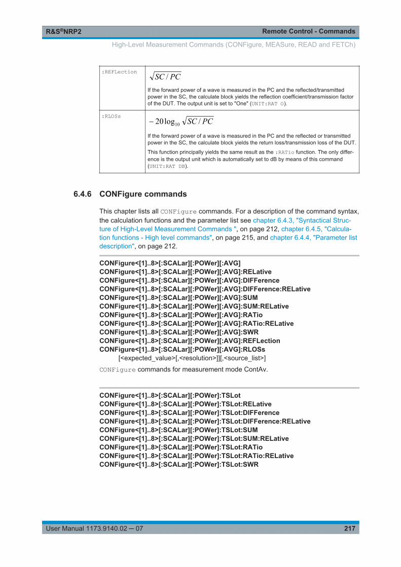
Remote Control - CommandsR&S®NRP2
217User Manual 1173.9140.02 ─ 07
:REFLection PCSC /If the forward power of a wave is measured in the PC and the reflected/transmittedpower in the SC, the calculate block yields the reflection coefficient/transmission factorof the DUT. The output unit is set to "One" (UNIT:RAT O).
:RLOSs PCSC /log20 10
If the forward power of a wave is measured in the PC and the reflected or transmittedpower in the SC, the calculate block yields the return loss/transmission loss of the DUT.
This function principally yields the same result as the :RATio function. The only differ-ence is the output unit which is automatically set to dB by means of this command(UNIT:RAT DB).
6.4.6 CONFigure commands
This chapter lists all CONFigure commands. For a description of the command syntax,the calculation functions and the parameter list see chapter 6.4.3, "Syntactical Struc-ture of High-Level Measurement Commands ", on page 212, chapter 6.4.5, "Calcula-tion functions - High level commands", on page 215, and chapter 6.4.4, "Parameter listdescription", on page 212.
CONFigure<[1]..8>[:SCALar][:POWer][:AVG]CONFigure<[1]..8>[:SCALar][:POWer][:AVG]:RELativeCONFigure<[1]..8>[:SCALar][:POWer][:AVG]:DIFFerenceCONFigure<[1]..8>[:SCALar][:POWer][:AVG]:DIFFerence:RELativeCONFigure<[1]..8>[:SCALar][:POWer][:AVG]:SUMCONFigure<[1]..8>[:SCALar][:POWer][:AVG]:SUM:RELativeCONFigure<[1]..8>[:SCALar][:POWer][:AVG]:RATioCONFigure<[1]..8>[:SCALar][:POWer][:AVG]:RATio:RELativeCONFigure<[1]..8>[:SCALar][:POWer][:AVG]:SWRCONFigure<[1]..8>[:SCALar][:POWer][:AVG]:REFLectionCONFigure<[1]..8>[:SCALar][:POWer][:AVG]:RLOSs
[<expected_value>[,<resolution>]][,<source_list>]
CONFigure commands for measurement mode ContAv.
CONFigure<[1]..8>[:SCALar][:POWer]:TSLotCONFigure<[1]..8>[:SCALar][:POWer]:TSLot:RELativeCONFigure<[1]..8>[:SCALar][:POWer]:TSLot:DIFFerenceCONFigure<[1]..8>[:SCALar][:POWer]:TSLot:DIFFerence:RELativeCONFigure<[1]..8>[:SCALar][:POWer]:TSLot:SUMCONFigure<[1]..8>[:SCALar][:POWer]:TSLot:SUM:RELativeCONFigure<[1]..8>[:SCALar][:POWer]:TSLot:RATioCONFigure<[1]..8>[:SCALar][:POWer]:TSLot:RATio:RELativeCONFigure<[1]..8>[:SCALar][:POWer]:TSLot:SWR
High-Level Measurement Commands (CONFigure, MEASure, READ and FETCh)
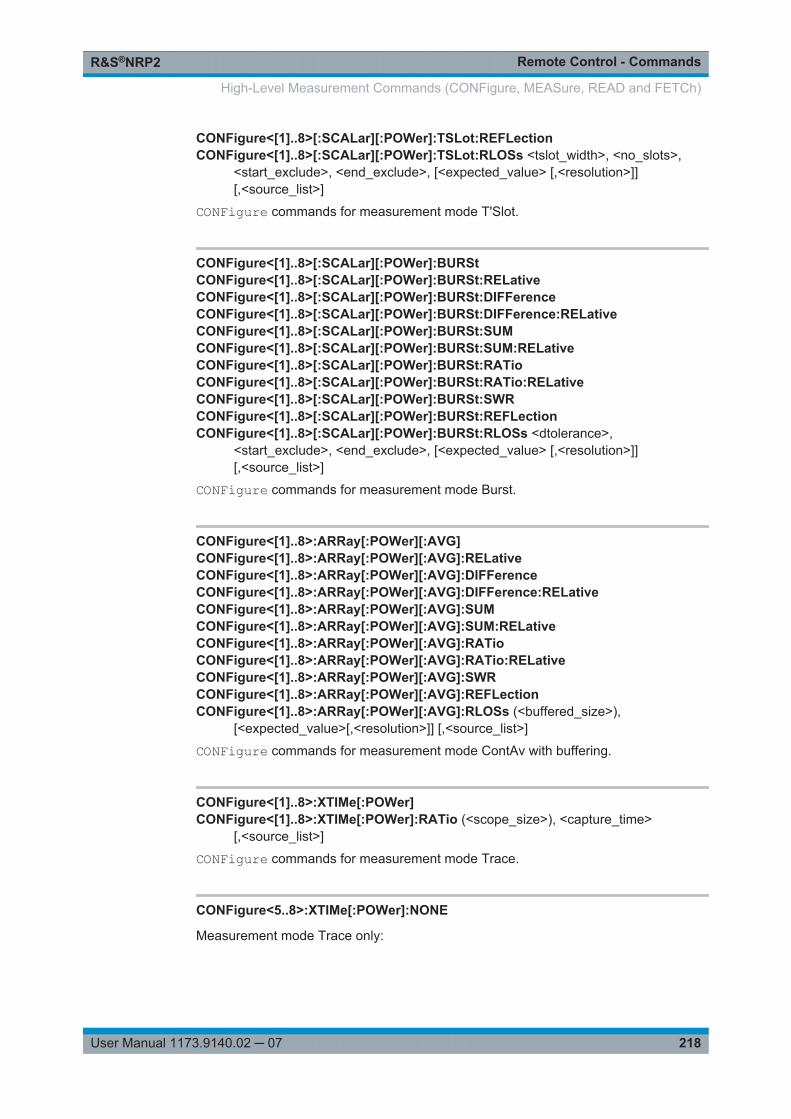
Remote Control - CommandsR&S®NRP2
218User Manual 1173.9140.02 ─ 07
CONFigure<[1]..8>[:SCALar][:POWer]:TSLot:REFLectionCONFigure<[1]..8>[:SCALar][:POWer]:TSLot:RLOSs <tslot_width>, <no_slots>,
<start_exclude>, <end_exclude>, [<expected_value> [,<resolution>]][,<source_list>]
CONFigure commands for measurement mode T'Slot.
CONFigure<[1]..8>[:SCALar][:POWer]:BURStCONFigure<[1]..8>[:SCALar][:POWer]:BURSt:RELativeCONFigure<[1]..8>[:SCALar][:POWer]:BURSt:DIFFerenceCONFigure<[1]..8>[:SCALar][:POWer]:BURSt:DIFFerence:RELativeCONFigure<[1]..8>[:SCALar][:POWer]:BURSt:SUMCONFigure<[1]..8>[:SCALar][:POWer]:BURSt:SUM:RELativeCONFigure<[1]..8>[:SCALar][:POWer]:BURSt:RATioCONFigure<[1]..8>[:SCALar][:POWer]:BURSt:RATio:RELativeCONFigure<[1]..8>[:SCALar][:POWer]:BURSt:SWRCONFigure<[1]..8>[:SCALar][:POWer]:BURSt:REFLectionCONFigure<[1]..8>[:SCALar][:POWer]:BURSt:RLOSs <dtolerance>,
<start_exclude>, <end_exclude>, [<expected_value> [,<resolution>]][,<source_list>]
CONFigure commands for measurement mode Burst.
CONFigure<[1]..8>:ARRay[:POWer][:AVG]CONFigure<[1]..8>:ARRay[:POWer][:AVG]:RELativeCONFigure<[1]..8>:ARRay[:POWer][:AVG]:DIFFerenceCONFigure<[1]..8>:ARRay[:POWer][:AVG]:DIFFerence:RELativeCONFigure<[1]..8>:ARRay[:POWer][:AVG]:SUMCONFigure<[1]..8>:ARRay[:POWer][:AVG]:SUM:RELativeCONFigure<[1]..8>:ARRay[:POWer][:AVG]:RATioCONFigure<[1]..8>:ARRay[:POWer][:AVG]:RATio:RELativeCONFigure<[1]..8>:ARRay[:POWer][:AVG]:SWRCONFigure<[1]..8>:ARRay[:POWer][:AVG]:REFLectionCONFigure<[1]..8>:ARRay[:POWer][:AVG]:RLOSs (<buffered_size>),
[<expected_value>[,<resolution>]] [,<source_list>]
CONFigure commands for measurement mode ContAv with buffering.
CONFigure<[1]..8>:XTIMe[:POWer]CONFigure<[1]..8>:XTIMe[:POWer]:RATio (<scope_size>), <capture_time>
[,<source_list>]
CONFigure commands for measurement mode Trace.
CONFigure<5..8>:XTIMe[:POWer]:NONE
Measurement mode Trace only:
High-Level Measurement Commands (CONFigure, MEASure, READ and FETCh)
Remote Control - CommandsR&S®NRP2
219User Manual 1173.9140.02 ─ 07
Deactivates trace 2. In contrast to trace 1 which is always active, trace 2 can be deacti-vated. Trace 2 is associated with CALCulate5..8 and therefore, also with CONFig-ure5...8 (see also chapter 6.5, "CALCulate (Configuration of Calculate Blocks)",on page 224).
Usage: Event
CONFigure<[1]..8>:STATistics:CCDFCONFigure<[1]..8>:STATistics:PDF (<statistics_size>), <capture_time>
[,<source_list>]
CONFigure commands for measurement mode Statistics.
6.4.7 Fetch commands
This chapter lists all FETCh commands. For a description of the command syntax, thecalculation functions and the parameter list see chapter 6.4.3, "Syntactical Structure ofHigh-Level Measurement Commands ", on page 212, chapter 6.4.5, "Calculation func-tions - High level commands", on page 215, and chapter 6.4.4, "Parameter list descrip-tion", on page 212.
FETCh<[1]..8>[:SCALar][:POWer][:AVG]FETCh<[1]..8>[:SCALar][:POWer][:AVG]:RELativeFETCh<[1]..8>[:SCALar][:POWer][:AVG]:DIFFerenceFETCh<[1]..8>[:SCALar][:POWer][:AVG]:DIFFerence:RELativeFETCh<[1]..8>[:SCALar][:POWer][:AVG]:SUMFETCh<[1]..8>[:SCALar][:POWer][:AVG]:SUM:RELativeFETCh<[1]..8>[:SCALar][:POWer][:AVG]:RATioFETCh<[1]..8>[:SCALar][:POWer][:AVG]:RATio:RELativeFETCh<[1]..8>[:SCALar][:POWer][:AVG]:SWRFETCh<[1]..8>[:SCALar][:POWer][:AVG]:REFLectionFETCh<[1]..8>[:SCALar][:POWer][:AVG]:RLOSs [<expected_value>[,<resolution>]]
[,<source_list>]
FETCh commands for measurement mode ContAv.
FETCh<[1]..8>[:SCALar][:POWer]:TSLotFETCh<[1]..8>[:SCALar][:POWer]:TSLot:RELativeFETCh<[1]..8>[:SCALar][:POWer]:TSLot:DIFFerenceFETCh<[1]..8>[:SCALar][:POWer]:TSLot:DIFFerence:RELativeFETCh<[1]..8>[:SCALar][:POWer]:TSLot:SUMFETCh<[1]..8>[:SCALar][:POWer]:TSLot:SUM:RELativeFETCh<[1]..8>[:SCALar][:POWer]:TSLot:RATioFETCh<[1]..8>[:SCALar][:POWer]:TSLot:RATio:RELativeFETCh<[1]..8>[:SCALar][:POWer]:TSLot:SWR
High-Level Measurement Commands (CONFigure, MEASure, READ and FETCh)
Remote Control - CommandsR&S®NRP2
220User Manual 1173.9140.02 ─ 07
FETCh<[1]..8>[:SCALar][:POWer]:TSLot:REFLectionFETCh<[1]..8>[:SCALar][:POWer]:TSLot:RLOSs <tslot_width>, <no_slots>,
<start_exclude>, <end_exclude>, [<expected_value> [,<resolution>]][,<source_list>]
FETCh commands for measurement mode T'Slot.
FETCh<[1]..8>[:SCALar][:POWer]:BURStFETCh<[1]..8>[:SCALar][:POWer]:BURSt:RELativeFETCh<[1]..8>[:SCALar][:POWer]:BURSt:DIFFerenceFETCh<[1]..8>[:SCALar][:POWer]:BURSt:DIFFerence:RELativeFETCh<[1]..8>[:SCALar][:POWer]:BURSt:SUMFETCh<[1]..8>[:SCALar][:POWer]:BURSt:SUM:RELativeFETCh<[1]..8>[:SCALar][:POWer]:BURSt:RATioFETCh<[1]..8>[:SCALar][:POWer]:BURSt:RATio:RELativeFETCh<[1]..8>[:SCALar][:POWer]:BURSt:SWRFETCh<[1]..8>[:SCALar][:POWer]:BURSt:REFLectionFETCh<[1]..8>[:SCALar][:POWer]:BURSt:RLOSs <dtolerance>, <start_exclude>,
<end_exclude>, [<expected_value> [,<resolution>]] [,<source_list>]
FETCh commands for measurement mode Burst.
FETCh<[1]..8>:ARRay[:POWer][:AVG]FETCh<[1]..8>:ARRay[:POWer][:AVG]:RELativeFETCh<[1]..8>:ARRay[:POWer][:AVG]:DIFFerenceFETCh<[1]..8>:ARRay[:POWer][:AVG]:DIFFerence:RELativeFETCh<[1]..8>:ARRay[:POWer][:AVG]:SUMFETCh<[1]..8>:ARRay[:POWer][:AVG]:SUM:RELativeFETCh<[1]..8>:ARRay[:POWer][:AVG]:RATioFETCh<[1]..8>:ARRay[:POWer][:AVG]:RATio:RELativeFETCh<[1]..8>:ARRay[:POWer][:AVG]:SWRFETCh<[1]..8>:ARRay[:POWer][:AVG]:REFLectionFETCh<[1]..8>:ARRay[:POWer][:AVG]:RLOSs (<buffered_size>),
[<expected_value>[,<resolution>]] [,<source_list>]
FETCh commands for measurement mode ContAv with buffering.
FETCh<[1]..8>:XTIMe[:POWer]FETCh<[1]..8>:XTIMe[:POWer]:RATio (<scope_size>), <capture_time>
[,<source_list>]
FETCh commands for measurement mode Trace.
FETCh<[1]..8>:STATistics:CCDFFETCh<[1]..8>:STATistics:PDF (<statistics_size>), <capture_time> [,<source_list>]
FETCh commands for measurement mode Statistics.
High-Level Measurement Commands (CONFigure, MEASure, READ and FETCh)
Remote Control - CommandsR&S®NRP2
221User Manual 1173.9140.02 ─ 07
6.4.8 READ commands
This chapter lists all READ commands. For a description of the command syntax, thecalculation functions and the parameter list see chapter 6.4.3, "Syntactical Structure ofHigh-Level Measurement Commands ", on page 212, chapter 6.4.5, "Calculation func-tions - High level commands", on page 215, and chapter 6.4.4, "Parameter list descrip-tion", on page 212.
READ<[1]..8>[:SCALar][:POWer][:AVG]READ<[1]..8>[:SCALar][:POWer][:AVG]:RELativeREAD<[1]..8>[:SCALar][:POWer][:AVG]:DIFFerenceREAD<[1]..8>[:SCALar][:POWer][:AVG]:DIFFerence:RELativeREAD<[1]..8>[:SCALar][:POWer][:AVG]:SUMREAD<[1]..8>[:SCALar][:POWer][:AVG]:SUM:RELativeREAD<[1]..8>[:SCALar][:POWer][:AVG]:RATioREAD<[1]..8>[:SCALar][:POWer][:AVG]:RATio:RELativeREAD<[1]..8>[:SCALar][:POWer][:AVG]:SWRREAD<[1]..8>[:SCALar][:POWer][:AVG]:REFLectionREAD<[1]..8>[:SCALar][:POWer][:AVG]:RLOSs [<expected_value>[,<resolution>]]
[,<source_list>]
READ commands for measurement mode ContAv.
READ<[1]..8>[:SCALar][:POWer]:TSLotREAD<[1]..8>[:SCALar][:POWer]:TSLot:RELativeREAD<[1]..8>[:SCALar][:POWer]:TSLot:DIFFerenceREAD<[1]..8>[:SCALar][:POWer]:TSLot:DIFFerence:RELativeREAD<[1]..8>[:SCALar][:POWer]:TSLot:SUMREAD<[1]..8>[:SCALar][:POWer]:TSLot:SUM:RELativeREAD<[1]..8>[:SCALar][:POWer]:TSLot:RATioREAD<[1]..8>[:SCALar][:POWer]:TSLot:RATio:RELativeREAD<[1]..8>[:SCALar][:POWer]:TSLot:SWRREAD<[1]..8>[:SCALar][:POWer]:TSLot:REFLectionREAD<[1]..8>[:SCALar][:POWer]:TSLot:RLOSs <tslot_width>, <no_slots>,
<start_exclude>, <end_exclude>, [<expected_value> [,<resolution>]][,<source_list>]
READ commands for measurement mode T'Slot.
READ<[1]..8>[:SCALar][:POWer]:BURStREAD<[1]..8>[:SCALar][:POWer]:BURSt:RELativeREAD<[1]..8>[:SCALar][:POWer]:BURSt:DIFFerenceREAD<[1]..8>[:SCALar][:POWer]:BURSt:DIFFerence:RELativeREAD<[1]..8>[:SCALar][:POWer]:BURSt:SUMREAD<[1]..8>[:SCALar][:POWer]:BURSt:SUM:RELativeREAD<[1]..8>[:SCALar][:POWer]:BURSt:RATioREAD<[1]..8>[:SCALar][:POWer]:BURSt:RATio:RELativeREAD<[1]..8>[:SCALar][:POWer]:BURSt:SWR
High-Level Measurement Commands (CONFigure, MEASure, READ and FETCh)
Remote Control - CommandsR&S®NRP2
222User Manual 1173.9140.02 ─ 07
READ<[1]..8>[:SCALar][:POWer]:BURSt:REFLectionREAD<[1]..8>[:SCALar][:POWer]:BURSt:RLOSs <dtolerance>, <start_exclude>,
<end_exclude>, [<expected_value> [,<resolution>]] [,<source_list>]
READ commands for measurement mode Burst.
READ<[1]..8>:ARRay[:POWer][:AVG]READ<[1]..8>:ARRay[:POWer][:AVG]:RELativeREAD<[1]..8>:ARRay[:POWer][:AVG]:DIFFerenceREAD<[1]..8>:ARRay[:POWer][:AVG]:DIFFerence:RELativeREAD<[1]..8>:ARRay[:POWer][:AVG]:SUMREAD<[1]..8>:ARRay[:POWer][:AVG]:SUM:RELativeREAD<[1]..8>:ARRay[:POWer][:AVG]:RATioREAD<[1]..8>:ARRay[:POWer][:AVG]:RATio:RELativeREAD<[1]..8>:ARRay[:POWer][:AVG]:SWRREAD<[1]..8>:ARRay[:POWer][:AVG]:REFLectionREAD<[1]..8>:ARRay[:POWer][:AVG]:RLOSs (<buffered_size>),
[<expected_value>[,<resolution>]] [,<source_list>]
READ commands for measurement mode ContAv with buffering.
READ<[1]..8>:XTIMe[:POWer]READ<[1]..8>:XTIMe[:POWer]:RATio (<scope_size>), <capture_time>
[,<source_list>]
READ commands for measurement mode Trace.
READ<[1]..8>:STATistics:CCDFREAD<[1]..8>:STATistics:PDF (<statistics_size>), <capture_time> [,<source_list>]
READ commands for measurement mode Statistics.
6.4.9 MEASurement commands
This chapter lists all MEASurement commands. For a description of the command syn-tax, the calculation functions and the parameter list see chapter 6.4.3, "SyntacticalStructure of High-Level Measurement Commands ", on page 212, chapter 6.4.5, "Cal-culation functions - High level commands", on page 215, and chapter 6.4.4, "Parame-ter list description", on page 212.
MEASurement<[1]..8>[:SCALar][:POWer][:AVG]MEASurement<[1]..8>[:SCALar][:POWer][:AVG]:RELativeMEASurement<[1]..8>[:SCALar][:POWer][:AVG]:DIFFerenceMEASurement<[1]..8>[:SCALar][:POWer][:AVG]:DIFFerence:RELativeMEASurement<[1]..8>[:SCALar][:POWer][:AVG]:SUMMEASurement<[1]..8>[:SCALar][:POWer][:AVG]:SUM:RELativeMEASurement<[1]..8>[:SCALar][:POWer][:AVG]:RATioMEASurement<[1]..8>[:SCALar][:POWer][:AVG]:RATio:RELative
High-Level Measurement Commands (CONFigure, MEASure, READ and FETCh)
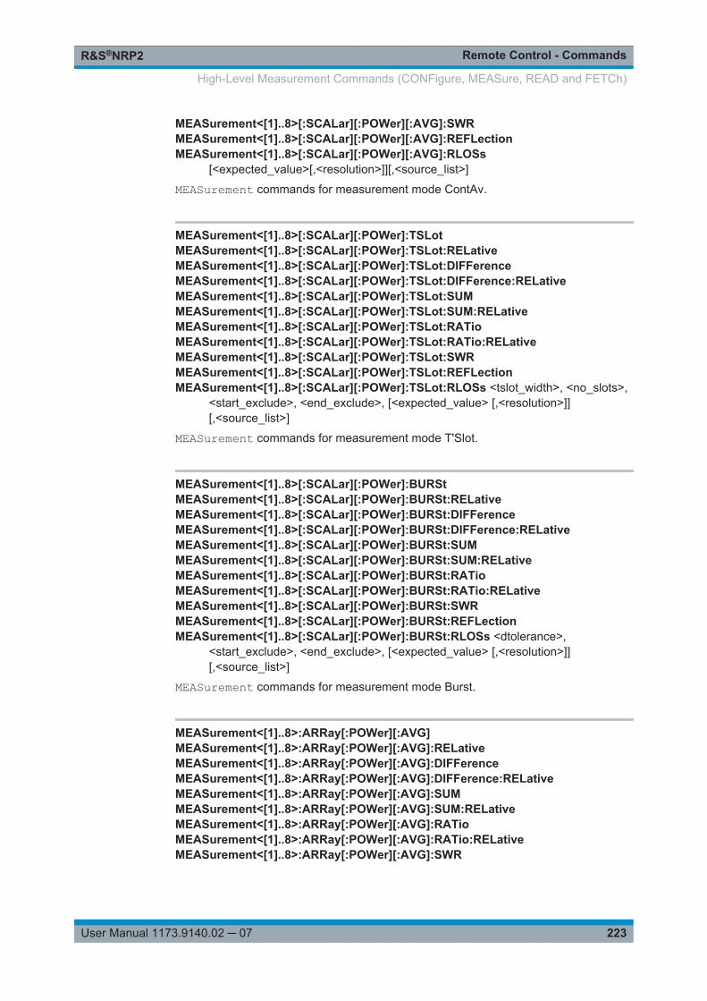
Remote Control - CommandsR&S®NRP2
223User Manual 1173.9140.02 ─ 07
MEASurement<[1]..8>[:SCALar][:POWer][:AVG]:SWRMEASurement<[1]..8>[:SCALar][:POWer][:AVG]:REFLectionMEASurement<[1]..8>[:SCALar][:POWer][:AVG]:RLOSs
[<expected_value>[,<resolution>]][,<source_list>]
MEASurement commands for measurement mode ContAv.
MEASurement<[1]..8>[:SCALar][:POWer]:TSLotMEASurement<[1]..8>[:SCALar][:POWer]:TSLot:RELativeMEASurement<[1]..8>[:SCALar][:POWer]:TSLot:DIFFerenceMEASurement<[1]..8>[:SCALar][:POWer]:TSLot:DIFFerence:RELativeMEASurement<[1]..8>[:SCALar][:POWer]:TSLot:SUMMEASurement<[1]..8>[:SCALar][:POWer]:TSLot:SUM:RELativeMEASurement<[1]..8>[:SCALar][:POWer]:TSLot:RATioMEASurement<[1]..8>[:SCALar][:POWer]:TSLot:RATio:RELativeMEASurement<[1]..8>[:SCALar][:POWer]:TSLot:SWRMEASurement<[1]..8>[:SCALar][:POWer]:TSLot:REFLectionMEASurement<[1]..8>[:SCALar][:POWer]:TSLot:RLOSs <tslot_width>, <no_slots>,
<start_exclude>, <end_exclude>, [<expected_value> [,<resolution>]][,<source_list>]
MEASurement commands for measurement mode T'Slot.
MEASurement<[1]..8>[:SCALar][:POWer]:BURStMEASurement<[1]..8>[:SCALar][:POWer]:BURSt:RELativeMEASurement<[1]..8>[:SCALar][:POWer]:BURSt:DIFFerenceMEASurement<[1]..8>[:SCALar][:POWer]:BURSt:DIFFerence:RELativeMEASurement<[1]..8>[:SCALar][:POWer]:BURSt:SUMMEASurement<[1]..8>[:SCALar][:POWer]:BURSt:SUM:RELativeMEASurement<[1]..8>[:SCALar][:POWer]:BURSt:RATioMEASurement<[1]..8>[:SCALar][:POWer]:BURSt:RATio:RELativeMEASurement<[1]..8>[:SCALar][:POWer]:BURSt:SWRMEASurement<[1]..8>[:SCALar][:POWer]:BURSt:REFLectionMEASurement<[1]..8>[:SCALar][:POWer]:BURSt:RLOSs <dtolerance>,
<start_exclude>, <end_exclude>, [<expected_value> [,<resolution>]][,<source_list>]
MEASurement commands for measurement mode Burst.
MEASurement<[1]..8>:ARRay[:POWer][:AVG]MEASurement<[1]..8>:ARRay[:POWer][:AVG]:RELativeMEASurement<[1]..8>:ARRay[:POWer][:AVG]:DIFFerenceMEASurement<[1]..8>:ARRay[:POWer][:AVG]:DIFFerence:RELativeMEASurement<[1]..8>:ARRay[:POWer][:AVG]:SUMMEASurement<[1]..8>:ARRay[:POWer][:AVG]:SUM:RELativeMEASurement<[1]..8>:ARRay[:POWer][:AVG]:RATioMEASurement<[1]..8>:ARRay[:POWer][:AVG]:RATio:RELativeMEASurement<[1]..8>:ARRay[:POWer][:AVG]:SWR
High-Level Measurement Commands (CONFigure, MEASure, READ and FETCh)
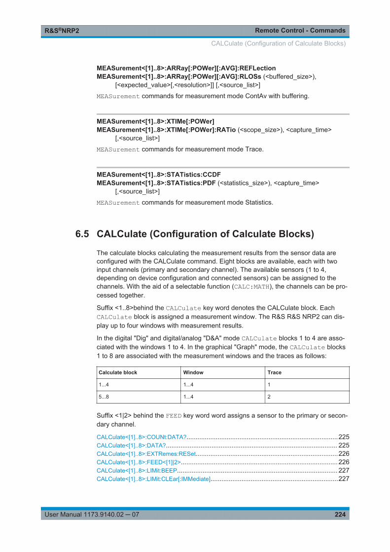
Remote Control - CommandsR&S®NRP2
224User Manual 1173.9140.02 ─ 07
MEASurement<[1]..8>:ARRay[:POWer][:AVG]:REFLectionMEASurement<[1]..8>:ARRay[:POWer][:AVG]:RLOSs (<buffered_size>),
[<expected_value>[,<resolution>]] [,<source_list>]
MEASurement commands for measurement mode ContAv with buffering.
MEASurement<[1]..8>:XTIMe[:POWer]MEASurement<[1]..8>:XTIMe[:POWer]:RATio (<scope_size>), <capture_time>
[,<source_list>]
MEASurement commands for measurement mode Trace.
MEASurement<[1]..8>:STATistics:CCDFMEASurement<[1]..8>:STATistics:PDF (<statistics_size>), <capture_time>
[,<source_list>]
MEASurement commands for measurement mode Statistics.
6.5 CALCulate (Configuration of Calculate Blocks)
The calculate blocks calculating the measurement results from the sensor data areconfigured with the CALCulate command. Eight blocks are available, each with twoinput channels (primary and secondary channel). The available sensors (1 to 4,depending on device configuration and connected sensors) can be assigned to thechannels. With the aid of a selectable function (CALC:MATH), the channels can be pro-cessed together.
Suffix <1..8>behind the CALCulate key word denotes the CALCulate block. EachCALCulate block is assigned a measurement window. The R&S R&S NRP2 can dis-play up to four windows with measurement results.
In the digital "Dig" and digital/analog "D&A" mode CALCulate blocks 1 to 4 are asso-ciated with the windows 1 to 4. In the graphical "Graph" mode, the CALCulate blocks1 to 8 are associated with the measurement windows and the traces as follows:
Calculate block Window Trace
1...4 1...4 1
5...8 1...4 2
Suffix <1|2> behind the FEED key word word assigns a sensor to the primary or secon-dary channel.
CALCulate<[1]..8>:COUNt:DATA?...................................................................................225CALCulate<[1]..8>:DATA?.............................................................................................. 225CALCulate<[1]..8>:EXTRemes:RESet..............................................................................226CALCulate<[1]..8>:FEED<[1]|2>...................................................................................... 226CALCulate<[1]..8>:LIMit:BEEP........................................................................................ 227CALCulate<[1]..8>:LIMit:CLEar[:IMMediate]......................................................................227
CALCulate (Configuration of Calculate Blocks)
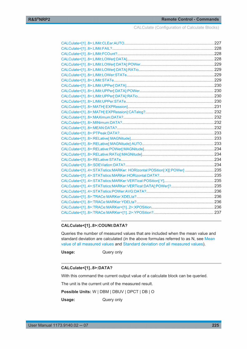
Remote Control - CommandsR&S®NRP2
225User Manual 1173.9140.02 ─ 07
CALCulate<[1]..8>:LIMit:CLEar:AUTO..............................................................................227CALCulate<[1]..8>:LIMit:FAIL?........................................................................................ 228CALCulate<[1]..8>:LIMit:FCOunt?....................................................................................228CALCulate<[1]..8>:LIMit:LOWer[:DATA]........................................................................... 228CALCulate<[1]..8>:LIMit:LOWer[:DATA]:POWer................................................................229CALCulate<[1]..8>:LIMit:LOWer[:DATA]:RATio................................................................. 229CALCulate<[1]..8>:LIMit:LOWer:STATe............................................................................229CALCulate<[1]..8>:LIMit:STATe.......................................................................................229CALCulate<[1]..8>:LIMit:UPPer[:DATA]............................................................................230CALCulate<[1]..8>:LIMit:UPPer[:DATA]:POWer................................................................ 230CALCulate<[1]..8>:LIMit:UPPer[:DATA]:RATio.................................................................. 230CALCulate<[1]..8>:LIMit:UPPer:STATe............................................................................ 230CALCulate<[1]..8>:MATH[:EXPRession]...........................................................................231CALCulate<[1]..8>:MATH[:EXPRession]:CATalog?........................................................... 232CALCulate<[1]..8>:MAXimum:DATA?.............................................................................. 232CALCulate<[1]..8>:MINimum:DATA?................................................................................232CALCulate<[1]..8>:MEAN:DATA?....................................................................................232CALCulate<[1]..8>:PTPeak:DATA?..................................................................................233CALCulate<[1]..8>:RELative[:MAGNitude]........................................................................ 233CALCulate<[1]..8>:RELative[:MAGNitude]:AUTO.............................................................. 233CALCulate<[1]..8>:RELative:POWer[:MAGNitude].............................................................234CALCulate<[1]..8>:RELative:RATio[:MAGNitude].............................................................. 234CALCulate<[1]..8>:RELative:STATe.................................................................................234CALCulate<[1]..8>:SDEViation:DATA?.............................................................................234CALCulate<[1]..4>:STATistics:MARKer: HORIzontal:POSition[:X][:POWer] .........................235CALCulate<[1]..4>:STATistics:MARKer:HORizontal:DATA?............................................... 235CALCulate<[1]..4>:STATistics:MARKer:VERTical:POSition[:Y]........................................... 235CALCulate<[1]..4>:STATistics:MARKer:VERTical:DATA[:POWer]?..................................... 235CALCulate<[1]..4>:STATistics:POWer:AVG:DATA?...........................................................236CALCulate<[1]..8>:TRACe:MARKer:XDELta?................................................................... 236CALCulate<[1]..8>:TRACe:MARKer:YDELta?................................................................... 236CALCulate<[1]..8>:TRACe:MARKer<[1]..2>:XPOSition...................................................... 236CALCulate<[1]..8>:TRACe:MARKer<[1]..2>:YPOSition?.................................................... 237
CALCulate<[1]..8>:COUNt:DATA?
Queries the number of measured values that are included when the mean value andstandard deviation are calculated (in the above formulas referred to as N, see Meanvalue of all measured values and Standard deviation σof all measured values).
Usage: Query only
CALCulate<[1]..8>:DATA?
With this command the current output value of a calculate block can be queried.
The unit is the current unit of the measured result.
Possible Units: W | DBM | DBUV | DPCT | DB | O
Usage: Query only
CALCulate (Configuration of Calculate Blocks)
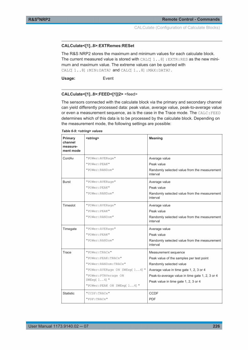
Remote Control - CommandsR&S®NRP2
226User Manual 1173.9140.02 ─ 07
CALCulate<[1]..8>:EXTRemes:RESet
The R&S NRP2 stores the maximum and minimum values for each calculate block.The current measured value is stored with CALC[1..8]:EXTR:RES as the new mini-mum and maximum value. The extreme values can be queried withCALC[1..8]:MIN:DATA? and CALC[1..8]:MAX:DATA?.
Usage: Event
CALCulate<[1]..8>:FEED<[1]|2> <feed>
The sensors connected with the calculate block via the primary and secondary channelcan yield differently processed data: peak value, average value, peak-to-average valueor even a measurement sequence, as is the case in the Trace mode. The CALC:FEEDdetermines which of this data is to be processed by the calculate block. Depending onthe measurement mode, the following settings are possible:
Table 6-9: <string> values
Primarychannelmeasure-ment mode
<string> Meaning
ContAv "POWer:AVERage""POWer:PEAK""POWer:RANDom"
Average value
Peak value
Randomly selected value from the measurementinterval
Burst "POWer:AVERage""POWer:PEAK""POWer:RANDom"
Average value
Peak value
Randomly selected value from the measurementinterval
Timeslot "POWer:AVERage""POWer:PEAK""POWer:RANDom"
Average value
Peak value
Randomly selected value from the measurementinterval
Timegate "POWer:AVERage""POWer:PEAK""POWer:RANDom"
Average value
Peak value
Randomly selected value from the measurementinterval
Trace "POWer:TRACe""POWer:PEAK:TRACe""POWer:RANDom:TRACe""POWer:AVERage ON SWEep[1..4]""POWer:PTAVerage ONSWEep[1..4]""POWer:PEAK ON SWEep[1..4]"
Measurement sequence
Peak value of the samples per test point
Randomly selected value
Average value in time gate 1, 2, 3 or 4
Peak-to-average value in time gate 1, 2, 3 or 4
Peak value in time gate 1, 2, 3 or 4
Statistic "CCDF:TRACe""PDF:TRACe"
CCDF
CALCulate (Configuration of Calculate Blocks)
Remote Control - CommandsR&S®NRP2
227User Manual 1173.9140.02 ─ 07
Note:
Every measured value displayed in the R&S NRP2 (also every point of a trace) is aver-aged in the sensor via a series of samples. If a RANDom feed is selected, a randomvalue is taken from these samples and forwarded to the base unit as a measuredvalue. PEAK is the maximum of all samples in the measurement interval.
Suffix: <[1]|2]>
.
Parameters:<feed> string
see table 6-9 <string> values.*RST: "POWer:AVERage"
CALCulate<[1]..8>:LIMit:BEEP <beep>
Switches the acoustic warning for limit violations on or off.
Parameters:<beep> ON | OFF
*RST: OFF
Usage: Setting only
CALCulate<[1]..8>:LIMit:CLEar[:IMMediate]
Resets the limit monitoring state and the internal counter for limit violations.
Usage: Event
CALCulate<[1]..8>:LIMit:CLEar:AUTO <auto>
Automatically resets the limit monitoring state and the internal counter for limit viola-tions if any of the following events occurs:● INITiate[:IMMediate] is executed● INITiate:CONTinuous ON is executed● MEASure? or MEASure:...? query is executed.● READ? or READ:...? query is executed.
CALCulate (Configuration of Calculate Blocks)
Remote Control - CommandsR&S®NRP2
228User Manual 1173.9140.02 ─ 07
Parameters:<auto> ON | OFF | ONCE
ONautomatic reset enabledOFFautomatic reset disabledONCEautomatic reset is enabled only once for the next occurrence ofthe above events*RST: OFF
Usage: Event
CALCulate<[1]..8>:LIMit:FAIL?
Queries whether upper or lower limits have been exceeded. The status is reset (0 = nolimit violation) if one of the following events occurs:● The device is switched on● A reset is performed (*RST)● The CALCulate<[1]..8>:LIMit:CLEar command is sent.
Usage: Query only
CALCulate<[1]..8>:LIMit:FCOunt?
Queries the number of limit violations that occurred. The counter is zeroed if one of thefollowing events occurs:● The device is switched on● A reset is performed (*RST)● The CALCulat<[1]..8>:LIMit:CLEar command is sent.
Usage: Query only
CALCulate<[1]..8>:LIMit:LOWer[:DATA] <lower_limit>
Sets a lower limit for the measured values. The R&S NRP2 can respond when the val-ues drop below this limit (see other CALCulate<[1]..8>:LIMit commands).
Parameters:<lower_limit> float_value
The value range depends on the current output unit of the calcu-late block's measured value, see table below.The parameter unit is determined according to table 6-11 Outputunit of measured value of calculate block.*RST: 0 DBM or 0 DBDefault unit: Default unit: see table referred to above.
CALCulate (Configuration of Calculate Blocks)

Remote Control - CommandsR&S®NRP2
229User Manual 1173.9140.02 ─ 07
Table 6-10: Value ranges, depending on the unit
Unit of mea-sured value
W DBM DBUV DPCT DB O
Value range -9.99999E5
..
9.99999E5
-120
..
90
-13.0103
..
196.897
-100
..
999.99
-200
..
200
-1E20
..
1E20
CALCulate<[1]..8>:LIMit:LOWer[:DATA]:POWer <lower_limit>
Sets a lower limit for the measured power. The R&S NRP2 can respond when the val-ues drop below this limit (see other CALCulate<[1]..8>:LIMit commands).
Parameters:<lower_limit> float_value; units: W | DBM | DBUV
Range: -120 DBM to 90 DBM*RST: 0 DBMDefault unit: DBM
CALCulate<[1]..8>:LIMit:LOWer[:DATA]:RATio <ratio>
Sets a lower limit for the measured power ratios. The R&S NRP2 can respond whenthe ratios drop below this limit (see other CALCulate<[1]..8>:LIMit commands).
Parameters:<ratio> float_value; units: DB | DBCT | O
Range: -200 DB to 200 DB*RST: 0 DBDefault unit: DB
CALCulate<[1]..8>:LIMit:LOWer:STATe <state>
Switches the monitoring function for theupper and lower limit on or off.
Parameters:<state> ON | OFF
*RST: OFF
Usage: Setting only
CALCulate<[1]..8>:LIMit:STATe <state>
Switches the monitoring function for the upper limit on or off.
Parameters:<state> ON | OFF
*RST: OFF
Usage: Setting only
CALCulate (Configuration of Calculate Blocks)
Remote Control - CommandsR&S®NRP2
230User Manual 1173.9140.02 ─ 07
CALCulate<[1]..8>:LIMit:UPPer[:DATA] <upper_limit>
Sets an upper limit for the measured values. The R&S NRP2 can respond when thislimit is exceeded (see other CALCulate<[1]..8>:LIMit commands).
Parameters:<upper_limit> float_value
The value range depends on the current output unit of the calcu-late block's measured value, as shown in table 6-10 Valueranges, depending on the unit.The parameter unit is determined according to table 6-11 Outputunit of measured value of calculate block.*RST: 0 DBM or 0 DBDefault unit: see table referred to above.
CALCulate<[1]..8>:LIMit:UPPer[:DATA]:POWer <power>
Sets a upper limit for the measured power. The R&S NRP2 can respond when this limitis exceeded (see other CALCulate[1]..8>:LIMit commands).
Parameters:<power> float_value; units: DBM | W | DBUV
Range: -120 DBM to 90 DBM*RST: 0 DBMDefault unit: DBM
CALCulate<[1]..8>:LIMit:UPPer[:DATA]:RATio <ratio>
Sets an upper limit for the measured power ratios. The R&S NRP2 can respond whenthis limit is exceeded (see other CALCulate<[1]..8>:LIMit commands).
Parameters:<ratio> float_value, units: DB | DPCT | O
Range: -200 DB to 200 DB*RST: 0 DBDefault unit: DB
CALCulate<[1]..8>:LIMit:UPPer:STATe <state>
Switches the monitoring function for the upper limit on or off.
Parameters:<state> ON | OFF
*RST: OFF
Usage: Setting only
CALCulate (Configuration of Calculate Blocks)
Remote Control - CommandsR&S®NRP2
231User Manual 1173.9140.02 ─ 07
CALCulate<[1]..8>:MATH[:EXPRession] <string>
Selects a measurement function that processes one sensor or two together. The resultof this calculation is made available as a measured value and can be queried withFETch<[1]..8>? or CALCulate<[1]..8>:DATA?.
The <string> parameter may assume the values given in the following table, n and mmay assume 1, 2, 3 and 4. A sensor must be connected to the respective channel.
Error messages:
-151 "Invalid string data": An invalid <string> parameter was transmitted.
string Meaning
"(SENS1)" The calculate block outputs the measured value of sensor A.
"(SENS2)" The calculate block outputs the measured value of sensor B.
"(SENS3)" The calculate block outputs the measured value of sensor C.
"(SENS4)" The calculate block outputs the measured value of sensor D.
"(SENSn-SENSm)" The calculate block outputs the difference between the measured values ofsensor n and sensor m.
"(SENSn+SENSm)" The calculate block outputs the sum of the measured values of sensor n andsensor m.
"(SENSn /SENSm)" The calculate block outputs the quotient of the values measured by sensor nand m.
"SWR(SENSn,SENSm)" SENSnSENSmSENSnSENSm
/1/1
If sensor n measures the forward power of a wave and sensor m the reflectedpower, the calculate block outputs the standing wave ratio of this wave. Theoutput unit is set to percent (UNIT:RAT PCT).
"REFL(SENSn,SENSm)" SENSnSENSm /
If sensor n measures the forward power of a wave and sensor m the reflec-ted/transmitted power, the calculate block outputs the reflection coefficient/transmission factor of a DUT. The output unit is set to percent (UNIT:RATPCT).
"RLOS(SENSn,SENSm)" SENSnSENSm /log20 10
If sensor n measures the forward power of a wave and sensor m the reflec-ted/transmitted power, the calculate block outputs the return loss/transmis-sion loss of a DUT. This function principally supplies the same result as the(SENSn/SENSm) function. The difference is that the output unit is automati-cally set to dB.
(UNIT:RAT DB).
CALCulate (Configuration of Calculate Blocks)
Remote Control - CommandsR&S®NRP2
232User Manual 1173.9140.02 ─ 07
Parameters:<string> string
The *RST values depend on the selected channel:CALC1:MATH: "(SENS1)",CALC2:MATH: "(SENS2)",CALC3:MATH: "(SENS3)",CALC4:MATH: "(SENS4)",CALC5:MATH: "(SENS1)",...CALC8:MATH: "(SENS1)".
CALCulate<[1]..8>:MATH[:EXPRession]:CATalog?
Lists all supported calculation functions. All functions are sent in the form of stringswhich are allowed as parameters for the CALCulate<[1]..8>:MATH:EXPRessioncommand.
Usage: Query only
CALCulate<[1]..8>:MAXimum:DATA?CALCulate<[1]..8>:MINimum:DATA?Queries the maximum/minimum of all measured values that previously occurred in thiscalculate block.
The limit value is set to the current measured value when● the device is switched on● a reset is performed (*RST)● the value is explicitly set to the current measured value using the command
CALCulate[1..8]:EXTRemes:RESet.
The unit is the current unit of the measured result.
Possible Units: W | DBM | DBUV | DPCT | DB | O
Usage: Query only
CALCulate<[1]..8>:MEAN:DATA?
Queries the mean value of all measured values of the calculate block. The mean valueis reset when the auxiliary values are reset. The following formula applies:
N
iixN
x1
1
Fig. 6-5: Mean value of all measured values
The unit is the current unit of the measured result.
Possible Units: W | DBM | DBUV | DPCT | DB | O
CALCulate (Configuration of Calculate Blocks)
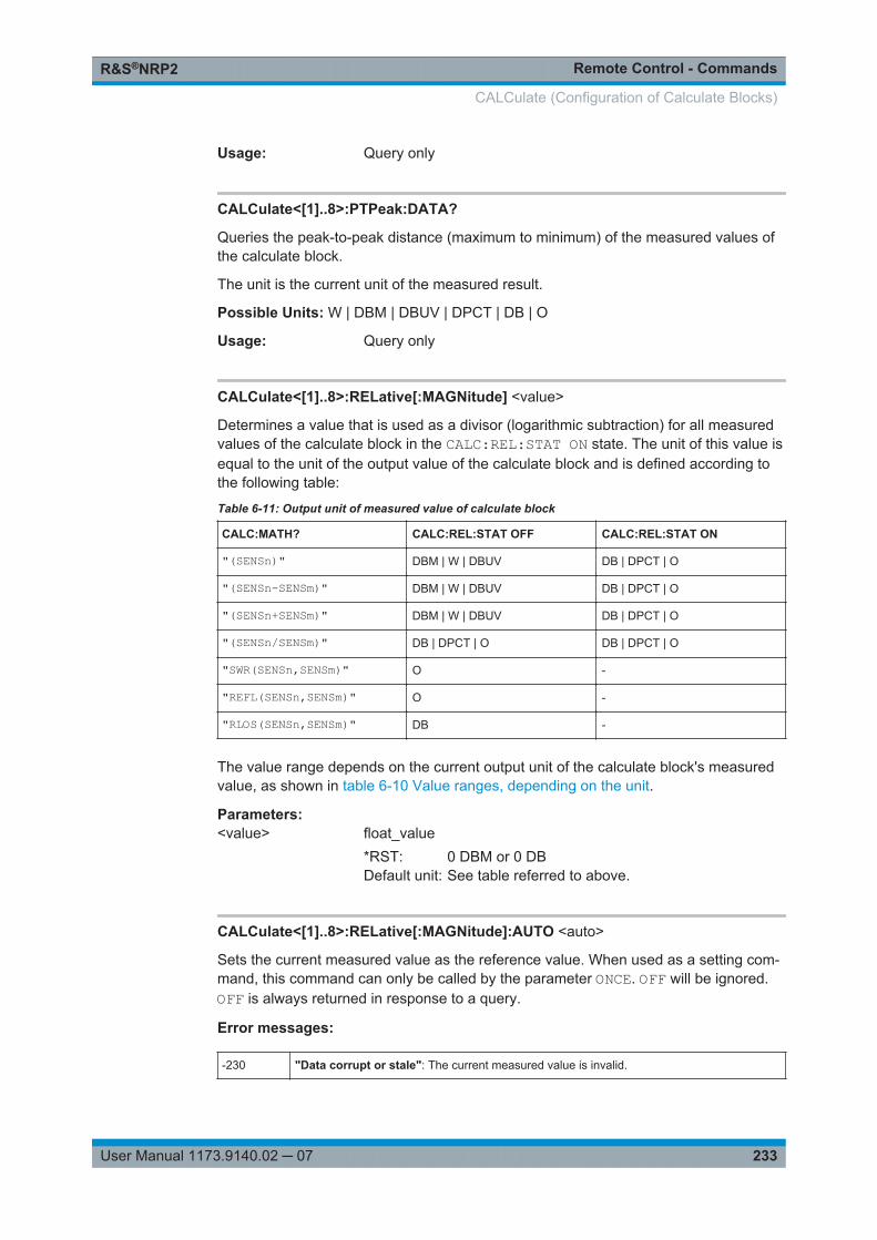
Remote Control - CommandsR&S®NRP2
233User Manual 1173.9140.02 ─ 07
Usage: Query only
CALCulate<[1]..8>:PTPeak:DATA?
Queries the peak-to-peak distance (maximum to minimum) of the measured values ofthe calculate block.
The unit is the current unit of the measured result.
Possible Units: W | DBM | DBUV | DPCT | DB | O
Usage: Query only
CALCulate<[1]..8>:RELative[:MAGNitude] <value>
Determines a value that is used as a divisor (logarithmic subtraction) for all measuredvalues of the calculate block in the CALC:REL:STAT ON state. The unit of this value isequal to the unit of the output value of the calculate block and is defined according tothe following table:
Table 6-11: Output unit of measured value of calculate block
CALC:MATH? CALC:REL:STAT OFF CALC:REL:STAT ON
"(SENSn)" DBM | W | DBUV DB | DPCT | O
"(SENSn-SENSm)" DBM | W | DBUV DB | DPCT | O
"(SENSn+SENSm)" DBM | W | DBUV DB | DPCT | O
"(SENSn/SENSm)" DB | DPCT | O DB | DPCT | O
"SWR(SENSn,SENSm)" O -
"REFL(SENSn,SENSm)" O -
"RLOS(SENSn,SENSm)" DB -
The value range depends on the current output unit of the calculate block's measuredvalue, as shown in table 6-10 Value ranges, depending on the unit.
Parameters:<value> float_value
*RST: 0 DBM or 0 DBDefault unit: See table referred to above.
CALCulate<[1]..8>:RELative[:MAGNitude]:AUTO <auto>
Sets the current measured value as the reference value. When used as a setting com-mand, this command can only be called by the parameter ONCE. OFF will be ignored.OFF is always returned in response to a query.
Error messages:
-230 "Data corrupt or stale": The current measured value is invalid.
CALCulate (Configuration of Calculate Blocks)
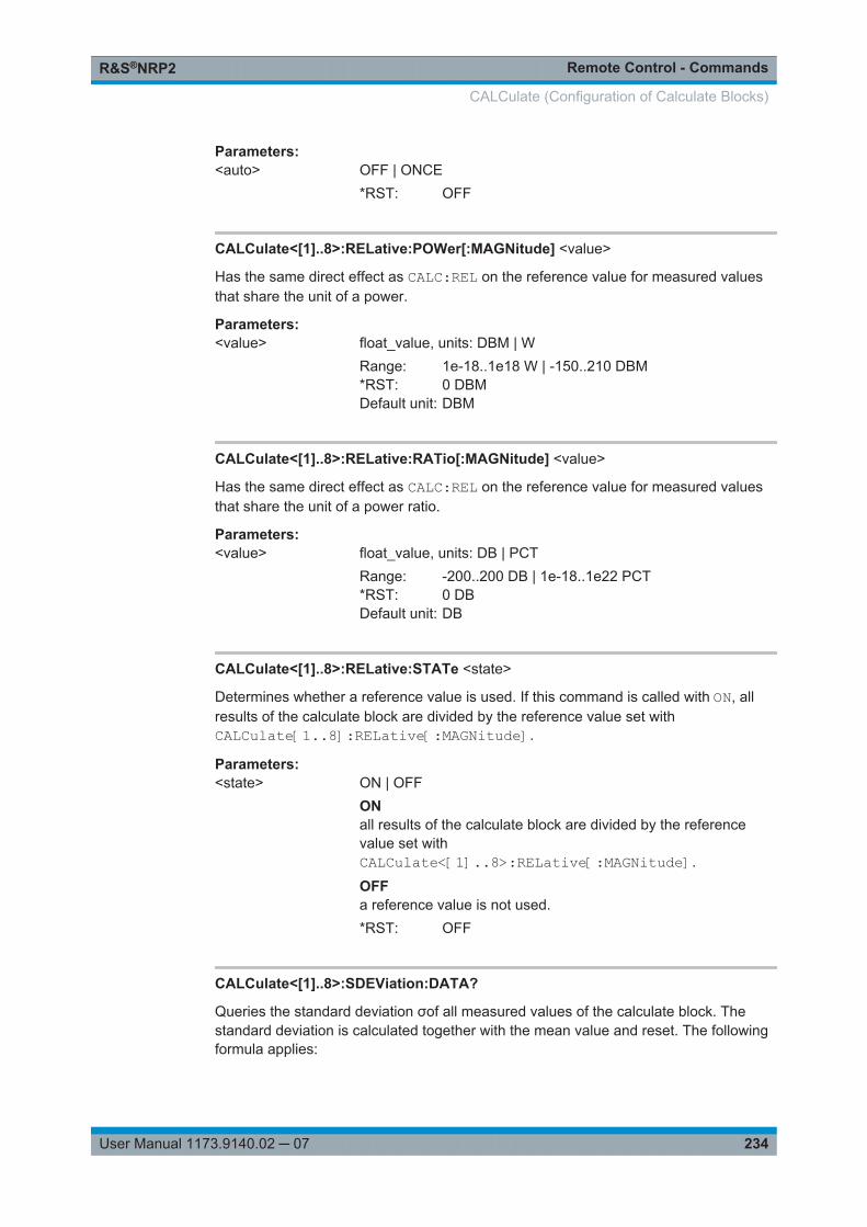
Remote Control - CommandsR&S®NRP2
234User Manual 1173.9140.02 ─ 07
Parameters:<auto> OFF | ONCE
*RST: OFF
CALCulate<[1]..8>:RELative:POWer[:MAGNitude] <value>
Has the same direct effect as CALC:REL on the reference value for measured valuesthat share the unit of a power.
Parameters:<value> float_value, units: DBM | W
Range: 1e-18..1e18 W | -150..210 DBM*RST: 0 DBMDefault unit: DBM
CALCulate<[1]..8>:RELative:RATio[:MAGNitude] <value>
Has the same direct effect as CALC:REL on the reference value for measured valuesthat share the unit of a power ratio.
Parameters:<value> float_value, units: DB | PCT
Range: -200..200 DB | 1e-18..1e22 PCT*RST: 0 DBDefault unit: DB
CALCulate<[1]..8>:RELative:STATe <state>
Determines whether a reference value is used. If this command is called with ON, allresults of the calculate block are divided by the reference value set withCALCulate[1..8]:RELative[:MAGNitude].
Parameters:<state> ON | OFF
ONall results of the calculate block are divided by the referencevalue set withCALCulate<[1]..8>:RELative[:MAGNitude].
OFFa reference value is not used.*RST: OFF
CALCulate<[1]..8>:SDEViation:DATA?
Queries the standard deviation σof all measured values of the calculate block. Thestandard deviation is calculated together with the mean value and reset. The followingformula applies:
CALCulate (Configuration of Calculate Blocks)
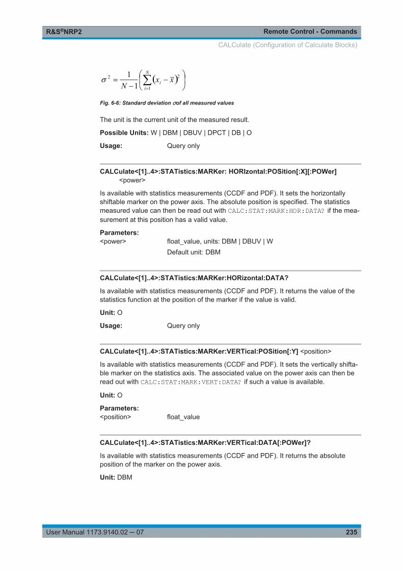
Remote Control - CommandsR&S®NRP2
235User Manual 1173.9140.02 ─ 07
N
ii xx
N 1
22
11
Fig. 6-6: Standard deviation σof all measured values
The unit is the current unit of the measured result.
Possible Units: W | DBM | DBUV | DPCT | DB | O
Usage: Query only
CALCulate<[1]..4>:STATistics:MARKer: HORIzontal:POSition[:X][:POWer]<power>
Is available with statistics measurements (CCDF and PDF). It sets the horizontallyshiftable marker on the power axis. The absolute position is specified. The statisticsmeasured value can then be read out with CALC:STAT:MARK:HOR:DATA? if the mea-surement at this position has a valid value.
Parameters:<power> float_value, units: DBM | DBUV | W
Default unit: DBM
CALCulate<[1]..4>:STATistics:MARKer:HORizontal:DATA?
Is available with statistics measurements (CCDF and PDF). It returns the value of thestatistics function at the position of the marker if the value is valid.
Unit: O
Usage: Query only
CALCulate<[1]..4>:STATistics:MARKer:VERTical:POSition[:Y] <position>
Is available with statistics measurements (CCDF and PDF). It sets the vertically shifta-ble marker on the statistics axis. The associated value on the power axis can then beread out with CALC:STAT:MARK:VERT:DATA? if such a value is available.
Unit: O
Parameters:<position> float_value
CALCulate<[1]..4>:STATistics:MARKer:VERTical:DATA[:POWer]?
Is available with statistics measurements (CCDF and PDF). It returns the absoluteposition of the marker on the power axis.
Unit: DBM
CALCulate (Configuration of Calculate Blocks)
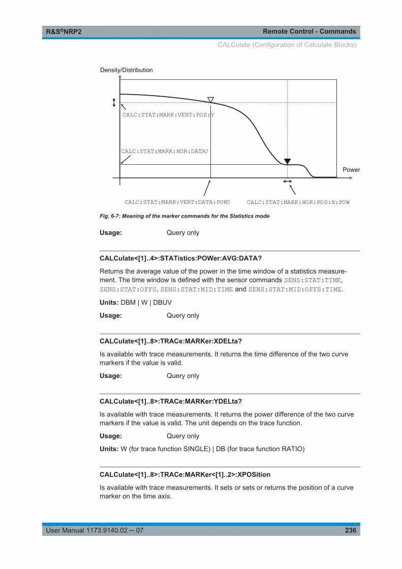
Remote Control - CommandsR&S®NRP2
236User Manual 1173.9140.02 ─ 07
Power
CALC:STAT:MARK:HOR:DATA?
CALC:STAT:MARK:VERT:POS:Y
Density/Distribution
CALC:STAT:MARK:HOR:POS:X:POWCALC:STAT:MARK:VERT:DATA:POW?
Fig. 6-7: Meaning of the marker commands for the Statistics mode
Usage: Query only
CALCulate<[1]..4>:STATistics:POWer:AVG:DATA?
Returns the average value of the power in the time window of a statistics measure-ment. The time window is defined with the sensor commands SENS:STAT:TIME,SENS:STAT:OFFS, SENS:STAT:MID:TIME and SENS:STAT:MID:OFFS:TIME.
Units: DBM | W | DBUV
Usage: Query only
CALCulate<[1]..8>:TRACe:MARKer:XDELta?
Is available with trace measurements. It returns the time difference of the two curvemarkers if the value is valid.
Usage: Query only
CALCulate<[1]..8>:TRACe:MARKer:YDELta?
Is available with trace measurements. It returns the power difference of the two curvemarkers if the value is valid. The unit depends on the trace function.
Usage: Query only
Units: W (for trace function SINGLE) | DB (for trace function RATIO)
CALCulate<[1]..8>:TRACe:MARKer<[1]..2>:XPOSition
Is available with trace measurements. It sets or sets or returns the position of a curvemarker on the time axis.
CALCulate (Configuration of Calculate Blocks)
Remote Control - CommandsR&S®NRP2
237User Manual 1173.9140.02 ─ 07
Unit: s
RST: 0 s
CALCulate<[1]..8>:TRACe:MARKer<[1]..2>:YPOSition?
Is available with trace measurements. It returns the position of a curve marker on thepower axis if the value is valid. The unit depends on the trace function.
Units: W (for trace function SINGLE) | DB (for trace function RATIO)
Usage: Query only
6.6 CALibration
Suffix [1]..4 denotes the four sensors. Calibration can be performed for only one ofthe sensors using header CALibration<[1]..4>:... or for all sensors usingheader CALibration:ALL:....
CALibration<[1]..4>:DATA...............................................................................................237CALibration<[1]..4>:ZERO:AUTO.....................................................................................237CALibration:ALL:ZERO:AUTO.........................................................................................237CALibration<[1]..4>:ZERO:FAST:AUTO........................................................................... 238CALibration:ALL:ZERO:FAST:AUTO................................................................................238
CALibration<[1]..4>:DATA <data>
Read and write binary calibration data sets for the selected sensor.
Parameters:<data> block_data
CALibration<[1]..4>:ZERO:AUTO <auto>CALibration:ALL:ZERO:AUTO <state>
Performs zeroing using the signal at the sensor input(s). The sensor(s) must be dis-connected from all power sources.
Error messages:
-231 "Data questionable; ZERO ERROR": Signal at the input considerably deviates from 0 W.
-224 "Illegal parameter value": The transfer parameter is a numeric value unequal 0 (corre-sponds to OFF).
The setting commands accept only the parameters ONCE, LFR and UFR, they start ofzeroing; OFF and ON are ignored.
The queries return the value ON if a calibration is in progress, otherwise value OFF.
CALibration
Remote Control - CommandsR&S®NRP2
238User Manual 1173.9140.02 ─ 07
The parameters LFR (lower frequency range) and UFR (upper frequency range) limitzeroing to a lower and an upper frequency range, thus reducing the required time byhalf. These parameters are not accepted by all sensors. Before using them, you shouldconsult the manual of the sensor concerned.
Another possibility to perform zeroing faster is to use the commandCALibration<[1]..4>:ZERO:FAST:AUTO in the trace mode.
The commands are overlapping, i.e. other commands can be sent to the R&S NRP2while one or more calibrations are running.
Zeroing is recommended if● the temperature has varied by more than about 5 °C,● the sensor has been replaced,● no zeroing was performed in the last 24 hours,● signals of very low power are to be measured, for instance, if the expected mea-
sured value is less than 10 dB above the lower measurement range limit.
Parameters:<state> ON | OFF | ONCE | LFR | UFR
*RST: OFF
CALibration<[1]..4>:ZERO:FAST:AUTO <state>CALibration:ALL:ZERO:FAST:AUTO <state>
Perform fast zeroing. However, the commands cannot be called unless the sensor(s)is(are) in the Trace mode. Since the commands are processed very quickly, they arenot overlapping. The queries therefore always return OFF.
Error messages:
-224 "Illegal parameter value": The transfer parameter is a numeric value unequal 0 (corre-sponds to OFF).
Parameters:<state> OFF | ONCE
*RST: OFF
6.7 DISPlay
The DISPlay command system is mainly used to configure the display of windows onthe R&S NRP2. The WINDow commands are assigned to the calculate blocks 1 to 4.The values calculated from the sensor values by the respective calculate block with theaid of the measurement function are displayed.
Suffix [1]..4 denotes the number of the calculate block.
DISPlay
Remote Control - CommandsR&S®NRP2
239User Manual 1173.9140.02 ─ 07
DISPlay:ERRorlist..........................................................................................................239DISPlay:ILLumination..................................................................................................... 239DISPlay:MESSage[:STATe]............................................................................................ 240DISPlay:MESSage:TEXT:CLEar......................................................................................240DISPlay:MESSage:TEXT[:DATA].....................................................................................240DISPlay:MESSage:TYPE................................................................................................240DISPlay:PIXMap?.......................................................................................................... 241DISPlay:UPDate............................................................................................................ 241DISPlay[:WINDow]<[1]..4>:AVALue................................................................................. 241DISPlay[:WINDow]<[1]..4>:FORMat.................................................................................242DISPlay[:WINDow]<[1]..4>:METer:AUTO..........................................................................243DISPlay[:WINDow]<[1]..4>:ANALog:AUTO....................................................................... 243DISPlay[:WINDow]<[1]..4>:METer:LOWer........................................................................ 243DISPlay[:WINDow]<[1]..4>:ANALog:LOWer......................................................................243DISPlay[:WINDow]<[1]..4>:METer:LOWer:POWer.............................................................244DISPlay[:WINDow]<[1]..4>:ANALog:LOWer:POWer.......................................................... 244DISPlay[:WINDow]<[1]..4>:METer:LOWer:RATio.............................................................. 244DISPlay[:WINDow]<[1]..4>:ANALog:LOWer:RATio............................................................ 244DISPlay[:WINDow]<[1]..4>:METer:UPPer......................................................................... 244DISPlay[:WINDow]<[1]..4>:ANALog:UPPer.......................................................................244DISPlay[:WINDow]<[1]..4>:METer:UPPer:POWer..............................................................244DISPlay[:WINDow]<[1]..4>:ANALog:UPPer:POWer........................................................... 244DISPlay[:WINDow]<[1]..4>:METer:UPPer:RATio............................................................... 245DISPlay[:WINDow]<[1]..4>:ANALog:UPPer:RATio.............................................................245DISPlay[:WINDow]<[1]..4>:NAME....................................................................................245DISPlay[:WINDow]<[1]..4>:RESolution.............................................................................245DISPlay[:WINDow]:SELect..............................................................................................246DISPlay[:WINDow]:SIZE.................................................................................................246DISPlay[:WINDow]<[1]..4>[:STATe]................................................................................. 247DISPlay[:WINDow]<[1]..4>:TRACe:LOWer....................................................................... 247DISPlay[:WINDow]<[1]..4>:TRACe:UPPer........................................................................ 247DISPlay[:WINDow]<[1]..4>:TSLot.....................................................................................248
DISPlay:ERRorlist <state>
Displays ON or removes OFF a windows which contains the contents of the SCPI errorqueue. The queue may be deleted by pressing the DEL key.
Parameters:<state> ON | OFF
*RST: OFF
DISPlay:ILLumination <state>
This command switches the backlighting ON or OFF. Backlighting is switched on againin case of a reset.
Note: DISP:ILL is identical to DISP:ENAB, see annex chapter A.5, "CompatibilityInformation", on page 401.
DISPlay
Remote Control - CommandsR&S®NRP2
240User Manual 1173.9140.02 ─ 07
Parameters:<state> ON | OFF
*RST: ON
DISPlay:MESSage[:STATe] <state>
Displays a window containing a user-defined message. The message text is definedvia DISP:MESS:TEXT. In addition, DISP:MESS:TYPE can select between two types ofmessage windows. Calling the command with the OFF parameter is ignored ifDISP:MESS:TYPE QUERy is set, because in this case a window must be closed bypressing the MENU key.
Parameters:<state> ON | OFF
*RST: OFF
DISPlay:MESSage:TEXT:CLEar
Deletes the stored text for user-defined messages.
Usage: Event
DISPlay:MESSage:TEXT[:DATA] <string>
Defines the text that can be displayed in a message window. The text can containASCII characters from code 32 (" ") to code 126 ("~"). The string "\n" is interpreted as aline break. Up to 4 lines (DISP:MESS:TYPE MESS) or up to 2 lines (DISP:MESS:TYPE QUERy) can be shown. The length of a line depends on the characters used,because a proportional font is used. Lines that are too long are cut off, which is indica-ted by "..." at the end of the line.
Usage: Event
DISPlay:MESSage:TYPE <message_type>
Sets the mode for the expected response to user-defined message windows.
Parameters:<message_type> QUERy | MESSage
QUERyThe message window must be closed by pressing the MENUkey. Until then, the execution of remote control commands isblocked.MESSageRemote control command processing is immediately continued.The message window must be closed with commandDISP:MESS OFF if it is no longer needed.
*RST: MESSage
DISPlay
Remote Control - CommandsR&S®NRP2
241User Manual 1173.9140.02 ─ 07
DISPlay:PIXMap?
Supplies the display content as binary block data. The block data consists of a blockdata header (#577110) and the display content in Microsoft Windows (R) BMP format(version 3). A color depth of 8 bit per pixel is used.
Parameters:<pixmap> block_data
Example: DISP:PIXM?returns:#577110xxxxxx...x,with x in binary format comprising an 8-bit BMP bitmap of thedisplay content.
Usage: Query only
DISPlay:UPDate <update_frequency>
Adjusts the update frequency of the measured values in the display. In case of discon-tinuities in the voltage progress at the analog outputs display updates may be suspen-ded with DISP:UPD FREeze. The display won't consume CPU time in this state.
Parameters:<update_frequency> NORMal | SLOW | FREeze
*RST: NORMal
DISPlay[:WINDow]<[1]..4>:AVALue <avalue>
Determines which additional information about the measured values is shown in thedisplay (right-hand side, next to the main measured values).
DISPlay
Remote Control - CommandsR&S®NRP2
242User Manual 1173.9140.02 ─ 07
Parameters:<avalue> NONE | NORMal | EXTRemes | STATistics
NONENo additional information about the measured values is dis-played.NORMalThe display is a function of the SENS:FUNCtion of the mea-surement mode of the primary channel and the CALC:FEED set-ting.Primary channel in the trace mode:The top line displays the frequency of the primary channel. Thetwo lower lines and the main measured value window displayAverage, Peak and PeakToAverage. CALC:FEED determineswhich of the three quantities is displayed in the main measuredvalue window. The other two quantities are displayed on theright-hand side, below the frequency.Primary channel not in the trace mode:Only the frequency of the primary channel and, if applicable, thefrequency of the secondary channel are displayed.EXTRemeMinimum, maximum and peak-to-peak (maximum to minimum)of all measured values displayed since the lastCALC:EXTR:RES, PowerOn or AuxVal Reset are shown (man-ual operation). With logarithmic units, the peak-to-peak valueequals the quotient of the measured values converted into linearunits.STATisticThe mean value, the standard deviation and the number of allmeasured values displayed since the last CALC:EXTR:RES,PowerOn or AuxVal Reset are shown (manual operation) (seealso CALCulate:...:DATA?).*RST: NONE
DISPlay[:WINDow]<[1]..4>:FORMat <display_mode>
Selects the display mode for measured data.
DISPlay
Remote Control - CommandsR&S®NRP2
243User Manual 1173.9140.02 ─ 07
Parameters:<display_mode> DIGital | ANALog | GRAPhical
DIGitalMeasured values are displayed in numeric format. If the primarychannel is operated in Trace mode, the (scalar) measured val-ues of the currently selected timegate are displayed here.ANALogMeasured values are indicated by a marker on a scale. The val-ues at the upper and lower scale end as well as the type of scal-ing (linear or logarithmic) are set with the following :METer com-mands.GRAPhicalMeasured values are plotted over time. This kind of presentationis possible only if the primary channel is operated in Tracemode.*RST: DIGital
DISPlay[:WINDow]<[1]..4>:METer:AUTO <auto>DISPlay[:WINDow]<[1]..4>:ANALog:AUTO <auto>
DISP:AUTO ONCE automatically determines scaling for the analog display. The upperand the lower limit value of the display is set as a function of the current measurementdata. Only the ONCE parameter is permissible; a query always supplies the value OFF.
Parameters:<auto> ONCE | OFF
*RST: OFF
DISPlay[:WINDow]<[1]..4>:METer:LOWer <lower_limit>DISPlay[:WINDow]<[1]..4>:ANALog:LOWer <lower_limit>
Sets the lower limit value of the analog scale.
The value range depends on the current output unit of the measured value of the win-dow.
Table 6-12: Value range
Unit of measured value W DBM PCT DB
Value range for <float_value> 1e-18..1e18 -150..210 1e-18..1e22 -200..200
Unit: See table 6-10 Value ranges, depending on the unit.
Parameters:<lower_limit> float_value
*RST: -90 DBM or -120 DB
DISPlay
Remote Control - CommandsR&S®NRP2
244User Manual 1173.9140.02 ─ 07
DISPlay[:WINDow]<[1]..4>:METer:LOWer:POWer <lower_power>DISPlay[:WINDow]<[1]..4>:ANALog:LOWer:POWer <lower_power>
Sets the lower limit value of the analog scale. This value is used if the unit of the mea-surement result is Watt, dBm or dBµV, i.e. the measurement result is a power.
Value range: See table 6-12 Value range.
Unit: DBM | W | DBUV
Parameters:<lower_power> float_value
*RST: -90 DBMDefault unit: DBM
DISPlay[:WINDow]<[1]..4>:METer:LOWer:RATio <lower_ratio>DISPlay[:WINDow]<[1]..4>:ANALog:LOWer:RATio <lower_ratio>
Sets the lower limit value of the analog scale. This value is used if the unit of the mea-surement result is dB, percent or the number 1, i.e. the measurement result is a powerratio.
Value range: See table 6-12 Value range.
Unit: DB | DPCT | O
Parameters:<lower_ratio> float_value
*RST: -120 DBDefault unit: DB
DISPlay[:WINDow]<[1]..4>:METer:UPPer <upper_limit>DISPlay[:WINDow]<[1]..4>:ANALog:UPPer <upper_limit>
Sets the upper limit value of the analog scale.
The value range depends on the current output unit of the measured value of the win-dow.
Unit: See table 6-10 Value ranges, depending on the unit.
Parameters:<upper_limit> float_value
*RST: 30 DBM or 60 DB
DISPlay[:WINDow]<[1]..4>:METer:UPPer:POWer <upper_limit>DISPlay[:WINDow]<[1]..4>:ANALog:UPPer:POWer <upper_limit>
Sets the upper limit value of the analog scale. This value is used if the unit of the mea-surement result is Watt, dBm or dBµV, i.e. the measurement result is a power.
Value range: See table 6-10 Value ranges, depending on the unit.
Unit: DBM | W | DBUV
DISPlay
Remote Control - CommandsR&S®NRP2
245User Manual 1173.9140.02 ─ 07
Parameters:<upper_limit> float_value
*RST: 30 DBMDefault unit: DBM
DISPlay[:WINDow]<[1]..4>:METer:UPPer:RATio <upper_limit>DISPlay[:WINDow]<[1]..4>:ANALog:UPPer:RATio <upper_limit>
Sets the upper limit value of the analog scale. This value is used if the unit of the mea-surement result is dB, percent or the number 1, i.e. the measurement result is a powerratio.
Value range: See table 6-10 Value ranges, depending on the unit.
Unit: DB | DPCT | O
Parameters:<upper_limit> float_value
*RST: 60 DBDefault unit: DB
DISPlay[:WINDow]<[1]..4>:NAME <string>
Determines the string to be displayed in the titlebar of the respective window. The resetvalues depend on the window (<n> = 1, 2, 3 or 4).
Parameters:<string> string
*RST: " "
Example: DISP1:NAME "Power In"DISP2:NAME "Power Out"The measured values in the display are now visually assigned tothe different test points in the test setup. (Input power in window1, output power in window 2).
DISPlay[:WINDow]<[1]..4>:RESolution <resolution>
Specifies the number of significant places of the mantissa when the measurementresult is displayed on a linear scale. The R&S NRP2 tries to adjust the averaging filterrange so that the display noise decreases with increasing resolution. The values of thetransfer parameter have the following meaning:
Parameter Linear scale of measurement result Logarithmic scale of measurementresult
1 1 significant place No decimal place
0.1 2 significant places 1 decimal place
0.01 3 significant places 2 decimal places
0.001 4 significant places 3 decimal places
DISPlay
Remote Control - CommandsR&S®NRP2
246User Manual 1173.9140.02 ─ 07
This command corresponds to the <resolution> option of the high-level measurementcommands CONFigure, FETCH, READ and MEASure.
Note:
Automatic filter ranging must be switched on(SENSe<[1]..4>:AVERage:COUNt:AUTO ON). DISP<[1]..8>:RES has an effecton the setting SENS<[1]..4>:AVER:COUN:AUTO:RES of the sensors used in themeasurement function (CALC<[1]..8>:MATH). However, the resolution setting of thesensors does not affect the resolution of values in the display.
Error messages:
-127 "Invalid numeric data": An invalid number was specified for the resolution.
Parameters:<resolution> 1 | 0.1 | 0.01 | 0.001
lin = Linear scale of measurement resultlog = Logarithmic scale of measurement result1lin = 1 significant placelog = No decimal place0.1lin = 2 significant placeslog = 1 decimal place0.01lin = 3 significant placeslog = 2 decimal places0.001lin = 4 significant placeslog = 3 decimal places*RST: 0.01
Example: DISP:WIND1:RES 0.1With a measured value of 123.456789 W, the first two placesare free of noise and thus 120 W is displayed.
DISPlay[:WINDow]:SELect <select_window>
Selects a window.
Parameters:<select_window> 1 | 2 | 3 | 4
*RST: 1
DISPlay[:WINDow]:SIZE <window_size>
Sets the window size.
DISPlay

Remote Control - CommandsR&S®NRP2
247User Manual 1173.9140.02 ─ 07
Parameters:<window_size> NORMal | ZOOMed
NORMalThe window size is determined automatically and depends onthe total number of open windows.ZOOMedThe selected window (DISP:WIND:SEL[?]) is set to maximumsize, regardless of the the number of visible windows. All otheropen windows are covered.*RST: NORMal
DISPlay[:WINDow]<[1]..4>[:STATe] <state>
Opens or closes a window. When a window is closed the other windows are automati-cally expanded so that the free space is utilized. Likewise, open windows becomesmaller when a new one is opened.
Parameters:<state> ON | OFF
*RST: ON (Window 1) | OFF (Window 2,3,4)
DISPlay[:WINDow]<[1]..4>:TRACe:LOWer <lower_limit>
Sets the lower limit for the power axis in the Trace mode. The value range depends onthe unit.
Table 6-13: The value range depends on the unit
Unit of measured value W DBM DBUV
Value range -999.999E3
..
999.999E3
-120
..
90
-13.010
..
136.990
Unit: DBM | W | DBUV
Parameters:<lower_limit> float_value
*RST: - 120 DBDefault unit: DBM
DISPlay[:WINDow]<[1]..4>:TRACe:UPPer <upper_limit>
Sets the upper limit for the power axis in the Trace mode.
Value range: See table 6-13 The value range depends on the unit.
Unit: DBM | W | DBUV
DISPlay
Remote Control - CommandsR&S®NRP2
248User Manual 1173.9140.02 ─ 07
Parameters:<upper_limit> float_value
*RST: 30 DBMDefault unit: DBM
DISPlay[:WINDow]<[1]..4>:TSLot <timeslot>
Sets the displayed timeslot, if the primary or secondary channel is operated in theTimeslot mode.
Parameters:<timeslot> int_value
Range: depending on sensor*RST: 1
6.8 FORMat
The FORMat command system sets the format of numeric data (measured values) thatis exchanged beween the remote control computer and the R&S NRP2 if high-levelmeasurement commands are used.
FORMat[:READings]:BORDer......................................................................................... 248FORMat[:READings][:DATA]........................................................................................... 248FORMat:SREGister........................................................................................................249
FORMat[:READings]:BORDer <mode>
Influences the order of bytes in 64-bit binary data.
Parameters:<mode> NORMal | SWAPped
NORMalThe 1st byte is the MSB (most significant byte), the 8th byte theLSB (least significant byte).This fulfills the Big Endian convention (Big Endian: "the big endcomes first").SWAPpedThe 1st byte is the LSB (least significant byte), the 8th byte theMSB (most significant byte).This fulfills the Little Endian convention.*RST: NORMal
FORMat[:READings][:DATA] <type>
Specifies whether numeric data is sent as block data in binary form (REAL) or as char-acter strings in plain text (ASCII).
FORMat
Remote Control - CommandsR&S®NRP2
249User Manual 1173.9140.02 ─ 07
Parameters:<type> ASCii | REAL
*RST: ASCii
FORMat:SREGister <format>
Specifies wich format s used for the return value of *STB?.
Parameters:<format> ASCii | BINary | HEXadecimal | OCTal
*RST: ASCii
6.9 MEMory
The MEMory system is used for storing device states (:STATe) and correction tables(:TABLe).
:STATe To allow a rapid and convenient changeover between device setups for differentapplications, up to 20 setups can be stored in the device. The setup with the number0 is the default setup made in the factory. This setup can neither be changed norcleared.
:TABLe Tables can be stored for a frequency-dependent correction of measured values. Upto 10 tables with two columns and up to 80 entries (lines) can be created. Thus, notonly the sensors but also the frequency response of various test assemblies can becompensated for during the measurement.
The tables are selected with [SENSe<[1]..4>]:CORRection:FDOTable[:SELect] on page 268 and then activated and deactivated with[SENSe<[1]..4>]:CORRection:FDOTable:STATe on page 268.
Names can be assigned to the tables. Some commands which do not specify a tablename affect the table currently selected with MEMory:TABLe:SELect on page 254.
Stored data is not affected by an *RST command.
MEMory:CATalog[:ALL]?................................................................................................ 250MEMory:CATalog:STATe?..............................................................................................250MEMory:CATalog:TABLe?.............................................................................................. 250MEMory:CLEar[:NAME].................................................................................................. 250MEMory:CLEar:TABLe................................................................................................... 251MEMory:FREE[:ALL]?.................................................................................................... 251MEMory:FREE:STATe?..................................................................................................251MEMory:FREE:TABLe?.................................................................................................. 251MEMory:NSTates?.........................................................................................................251MEMory:STATe:CATalog?..............................................................................................251MEMory:STATe:DEFine..................................................................................................252MEMory:STATe:MAP..................................................................................................... 252MEMory:STATe:RESet?................................................................................................. 252
MEMory
Remote Control - CommandsR&S®NRP2
250User Manual 1173.9140.02 ─ 07
MEMory:TABLe:DATA?.................................................................................................. 252MEMory:TABLe:DATA:POINts?.......................................................................................253MEMory:TABLe:FREQuency...........................................................................................253MEMory:TABLe:FREQuency:POINts?..............................................................................253MEMory:TABLe:GAIN[:MAGNitude]................................................................................. 253MEMory:TABLe:GAIN:POINts?....................................................................................... 254MEMory:TABLe:MAP..................................................................................................... 254MEMory:TABLe:MOVE...................................................................................................254MEMory:TABLe:RESet................................................................................................... 254MEMory:TABLe:SELect.................................................................................................. 254
MEMory:CATalog[:ALL]?
Lists the names of all stored device states and correction tables. The length of theresponse depends on how many device states and tables are stored.
Return values: <NR1>, <NR1>{,"<string>"}
The first two values denote the length in bytes of the occupiedRAM and of the RAM still available for storing states and tables.These values are followed by a string for each stored state andthen for each stored table; this string again consists of twostrings and a numeric value:<string>, <type>, <NR1><string> gives the name of the stored data item, <type> thetype (TABL or STAT) and <NR1> the length of the data item inbytes.
Example: The response to query MEM:CAT? could be:956,99044,"REFL,STAT,408","NRPZ21,TABL,432","SPLITTER1,TABL,116"
Usage: Query only
MEMory:CATalog:STATe?
Only gives a list of stored device states and is otherwise identical withMEMory:CATalog[:ALL]?.
Usage: Query only
MEMory:CATalog:TABLe?
Only gives a list of stored correction tables and is otherwise identical withMEMory:CATalog[:ALL]?.
Usage: Query only
MEMory:CLEar[:NAME] <name>
Clears the content of the correction table or the stored device state with the designa-tion <name>. The table is maintained but does not contain entries.
MEMory
Remote Control - CommandsR&S®NRP2
251User Manual 1173.9140.02 ─ 07
Notice: Possible data loss
This command cannot be cancelled. Cleared values are irretrievably lost.
Parameters:<name> string
Usage: Event
MEMory:CLEar:TABLe
This command may be used as an alternative to MEMory:CLEar[:NAME]<string>. The content of the table currently selected with MEMory:TABLe:SELect<string> is cleared.
Caution: Possible data loss
This command cannot be cancelled. Cleared values are irretrievably lost.
Usage: Event
MEMory:FREE[:ALL]?
Returns the number of bytes available in memory for storing correction tables anddevice states as well as the memory already used.
Usage: Query only
MEMory:FREE:STATe?
Returns the number of bytes available in memory for storing device states as well asthe memory already used for device states.
Usage: Query only
MEMory:FREE:TABLe?
Returns the number of bytes available in memory for storing device states as well asthe memory already used for device states.
Usage: Query only
MEMory:NSTates?
Returns the number of bytes available in memory for storing device states as well asthe memory already used for device states.
Usage: Query only
MEMory:STATe:CATalog?
Returns a list of names of stored device states.
MEMory
Remote Control - CommandsR&S®NRP2
252User Manual 1173.9140.02 ─ 07
Return values: <names>
Usage: Query only
MEMory:STATe:DEFine <string>, 1...19MEMory:STATe:MAP <string>
The value 0 to 19 are assigned to the memory locations of the device states, where thememory location with the number 0 is the factory-set state and cannot be changed.Names (<string>) can be assigned to these numbers with MEMory:STATe:DEFineor MEMory:STATe:MAP (except for the factory-set state).
The command MEMory:CLEar[:NAME] expects parameters that are actually stringsrather than the numbers of the memory locations. The default names of these memorylocations are "Setup 0" to "Setup 19". The name may contain the characters A to Z, ato z, 0 to 9 and "_".
The query of this command returns the number of the memory location with the nameof <string>.
Parameters:<string>, 1...19 maps the string on the selected memory location of the device
states
MEMory:STATe:RESet?
The command resets the names of the stored device states to factory default ("Setup1" etc.).
Usage: Query only
MEMory:TABLe:DATA? <f_n> {, <o_n>}
The command returns the content of the currently selected offset table. The answerconsists of an alternating comma separated list of frequencies (f_n, Hz) and offsets(o_n, dB).
Return values: <f_n> {, <o_n>} The answer consists of an alternating comma separated list of
frequencies (f_n) and offsets (o_n).*RST: Tables are not changed in case of a *RST.
Example: MEM:TABL:FREQ 50MHz,100MHzMEM:TABL:GAIN 1,1.1MEM:TABL:DATA?returned values:5.000000E+07,1.000000,1.000000E+08,1.100000
Usage: Query only
MEMory
Remote Control - CommandsR&S®NRP2
253User Manual 1173.9140.02 ─ 07
MEMory:TABLe:DATA:POINts?
The command returns the number of stored entries in the currently selected offsettable.
Usage: Query only
MEMory:TABLe:FREQuency <NRf> {, <NRf>}
This command enters frequencies in the first column of the table selected withMEM:TABL:SEL. Existing data for frequencies will be overwritten. The number of fre-quencies should match the number of offset values. If the number of frequencies dif-fers from the number of offset values, the shorter column length will be used.
SENS<[1]..4>:FREQ can be used to determine a frequency for which a correctionfactor is then defined by means of the offset table. If the exact frequency selected isnot in the table, the values in the table are interpolated. If the selected frequency is out-side the specified frequency range, the first or last offset value of the table is selected.Interpolation is linear in the units HZ and DB.
Parameters:<NRf> {, <NRf>} Enters frequencies in the first column of the table selected with
MEM:TABL:SEL*RST: Tables are not changed in case of a *RST.Default unit: HZ
MEMory:TABLe:FREQuency:POINts?
Returns the number of entries (lines) in the table selected with MEM:TABL:SEL<name>.
Usage: Query only
MEMory:TABLe:GAIN[:MAGNitude] <NRf> {, <NRf>}
This command enters offset values in the second column of the table selected withMEM:TABL:SEL. Existing data for offset values will be overwritten. The number of fre-quencies should match with the number of offset values. If the number of frequenciesdiffers from the number of offset values, the shorter column length will be used.
A frequency can be determined with SENS<[1]..4>:FREQ, for which a correction fac-tor is then calculated by means of the offset table. If the exact frequency selected is notin the table, the values in the table are interpolated. If the selected frequency is outsidethe specified frequency range, the first or last offset value of the table is selected. Inter-polation is linear in the units HZ and DB.
Unit: DB | PCT
MEMory
Remote Control - CommandsR&S®NRP2
254User Manual 1173.9140.02 ─ 07
Parameters:<NRf> {, <NRf>} Enters offset values in the second column of the table selected
with MEM:TABL:SEL.
*RST: Tables are not changed in case of a *RST.Default unit: DB
MEMory:TABLe:GAIN:POINts?
Returns the number of entries (lines) in the table selected with MEM:TABL:SEL<string>.
Usage: Query only
MEMory:TABLe:MAP <string>, 1...9
The numbers 0 to 9 are permanently assigned to the memory locations for devicestates. Names (<string>) can be assigned to the numbers with MEM:TABL:MAP. TheMEM:CLE[:NAME], MEM:TABL:MOVE and MEM:TABL:SEL commands expect thesenames as parameters, not the numbers of the memory locations. By default the tablesare assigned the names "Table 1" to "Table 10". The name can contain the characters"A" to "Z", "a" to "z", "0" to "9" and "_".
The query form of this command returns the number of the memory location with thename <map>.
Parameters:<string>, 1...9 maps the string on the selected memory locations for device
states.
MEMory:TABLe:MOVE <string>,<string>
This command allows tables to be renamed. The first parameter specifies the oldname, the second the new name. No data is copied, i.e. only the name of the tablechanges.
Example: MEM:TABL:MOVE "Table 1","Test setup"Renames the table "Table 1" into "Test setup" .
Usage: Setting only
MEMory:TABLe:RESet
The command clears all tables for frequency dependent offset.
Usage: Event
MEMory:TABLe:SELect <name>
Selects a table.
MEMory
Remote Control - CommandsR&S®NRP2
255User Manual 1173.9140.02 ─ 07
The following commands affect this table:● MEMory:CLEar[:NAMe] <string>● MEMory:CLEar:TABLe● all MEMory:TABLe commands
The selection is not changed in case of an *RST or a SYSTem:PRESetRST value: none
Error messages:
-256 "File name not found": A table named <select> is not known .
6.10 OUTPut
The OUTPut system serves for generator configuration. The R&S NRP2 can be equip-ped with an optional RF test generator which produces a reference power of 1 mW at50 MHz. Moreover, the analog outputs at the rear of the power meter can be config-ured.
OUTPut:RECorder<[1]..2>:FEED.....................................................................................255OUTPut:RECorder<[1]..2>:LIMit:LOWer........................................................................... 256OUTPut:RECorder<[1]..2>:LIMit:LOWer:POWer................................................................256OUTPut:RECorder<[1]..2>:LIMit:LOWer:RATio................................................................. 256OUTPut:RECorder<[1]..2>:LIMit:UPPer............................................................................257OUTPut:RECorder<[1]..2>:LIMit:UPPer:POWer................................................................ 257OUTPut:RECorder<[1]..2>:LIMit:UPPer:RATio.................................................................. 257OUTPut:RECorder<[1]..2>[:STATe]................................................................................. 258OUTPut:ROSCillator[:STATe]..........................................................................................258OUTPut:TTL:ACTive...................................................................................................... 258OUTPut:TTL:FAIL.......................................................................................................... 258OUTPut:TTL:FEED........................................................................................................ 259OUTPut:TTL:HVOLtage..................................................................................................259OUTPut:TTL:LVOLtage.................................................................................................. 259OUTPut:TTL[:STATe]..................................................................................................... 260OUTPut:TRIGger[:STATe].............................................................................................. 260
OUTPut:RECorder<[1]..2>:FEED <calculate_block>
Assigns a calculate block to one of the two analog outputs. On the basis of the setcharacteristic, the measured value is converted to a DC voltage that can be tapped atthe appropriate output.
Parameters:<calculate_block> "CALC1", "CALC2", "CALC3", "CALC4"
*RST: output 1: "CALC1"; output 2: "CALC2"
OUTPut
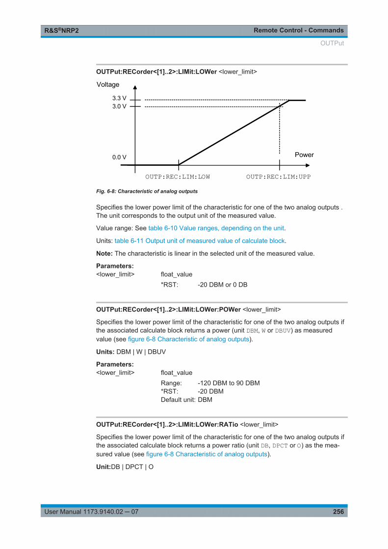
Remote Control - CommandsR&S®NRP2
256User Manual 1173.9140.02 ─ 07
OUTPut:RECorder<[1]..2>:LIMit:LOWer <lower_limit>
Power
Voltage
3.3 V
0.0 V
3.0 V
OUTP:REC:LIM:LOW OUTP:REC:LIM:UPP
Fig. 6-8: Characteristic of analog outputs
Specifies the lower power limit of the characteristic for one of the two analog outputs .The unit corresponds to the output unit of the measured value.
Value range: See table 6-10 Value ranges, depending on the unit.
Units: table 6-11 Output unit of measured value of calculate block.
Note: The characteristic is linear in the selected unit of the measured value.
Parameters:<lower_limit> float_value
*RST: -20 DBM or 0 DB
OUTPut:RECorder<[1]..2>:LIMit:LOWer:POWer <lower_limit>
Specifies the lower power limit of the characteristic for one of the two analog outputs ifthe associated calculate block returns a power (unit DBM, W or DBUV) as measuredvalue (see figure 6-8 Characteristic of analog outputs).
Units: DBM | W | DBUV
Parameters:<lower_limit> float_value
Range: -120 DBM to 90 DBM*RST: -20 DBMDefault unit: DBM
OUTPut:RECorder<[1]..2>:LIMit:LOWer:RATio <lower_limit>
Specifies the lower power limit of the characteristic for one of the two analog outputs ifthe associated calculate block returns a power ratio (unit DB, DPCT or O) as the mea-sured value (see figure 6-8 Characteristic of analog outputs).
Unit:DB | DPCT | O
OUTPut
Remote Control - CommandsR&S®NRP2
257User Manual 1173.9140.02 ─ 07
Parameters:<lower_limit> float_value
Range: -200 DB .. 200 DB*RST: 0 DBDefault unit: DB
OUTPut:RECorder<[1]..2>:LIMit:UPPer <upper_limit>
Specifies the upper power limit of the characteristic for one of the two analog outputs(see figure 6-8 Characteristic of analog outputs). The unit corresponds to the outputunit of the measured value.
Value range: See table 6-10 Value ranges, depending on the unit.
Unit: table 6-11 Output unit of measured value of calculate block.
Parameters:<upper_limit> float_value
*RST: 20 DBM or 10 DB
OUTPut:RECorder<[1]..2>:LIMit:UPPer:POWer <upper_limit>
Specifies the upper power limit of the characteristic for one of the two analog outputs ifthe associated calculate block returns a power (unit DBM, W or DBUV) as the measuredvalue (see figure 6-8 Characteristic of analog outputs).
Unit:DBM | W | DBUV
Parameters:<upper_limit> float_value
Range: -120 DBM to 90 DBM*RST: 20 DBMDefault unit: DBM
OUTPut:RECorder<[1]..2>:LIMit:UPPer:RATio <upper_limit>
Specifies the upper power limit of the characteristic for one of the two analog outputs ifthe associated calculate block returns a power ratio (unit DB, DPCT or O) as the mea-sured value (see figure 6-8 Characteristic of analog outputs).
Unit:DB | DPCT | O
Parameters:<upper_limit> float_value
Range: -200 DB .. 200 DB*RST: 10 DBDefault unit: DB
OUTPut
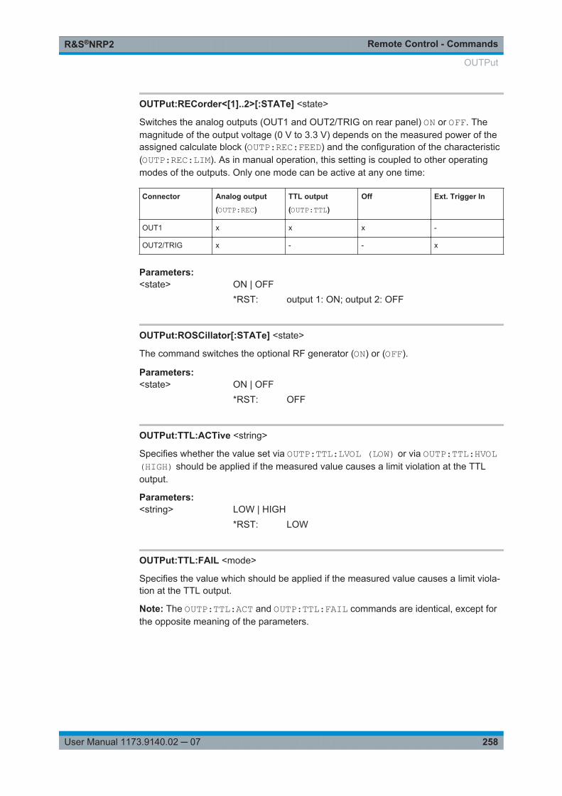
Remote Control - CommandsR&S®NRP2
258User Manual 1173.9140.02 ─ 07
OUTPut:RECorder<[1]..2>[:STATe] <state>
Switches the analog outputs (OUT1 and OUT2/TRIG on rear panel) ON or OFF. Themagnitude of the output voltage (0 V to 3.3 V) depends on the measured power of theassigned calculate block (OUTP:REC:FEED) and the configuration of the characteristic(OUTP:REC:LIM). As in manual operation, this setting is coupled to other operatingmodes of the outputs. Only one mode can be active at any one time:
Connector Analog output
(OUTP:REC)
TTL output
(OUTP:TTL)
Off Ext. Trigger In
OUT1 x x x -
OUT2/TRIG x - - x
Parameters:<state> ON | OFF
*RST: output 1: ON; output 2: OFF
OUTPut:ROSCillator[:STATe] <state>
The command switches the optional RF generator (ON) or (OFF).
Parameters:<state> ON | OFF
*RST: OFF
OUTPut:TTL:ACTive <string>
Specifies whether the value set via OUTP:TTL:LVOL (LOW) or via OUTP:TTL:HVOL(HIGH) should be applied if the measured value causes a limit violation at the TTLoutput.
Parameters:<string> LOW | HIGH
*RST: LOW
OUTPut:TTL:FAIL <mode>
Specifies the value which should be applied if the measured value causes a limit viola-tion at the TTL output.
Note: The OUTP:TTL:ACT and OUTP:TTL:FAIL commands are identical, except forthe opposite meaning of the parameters.
OUTPut
Remote Control - CommandsR&S®NRP2
259User Manual 1173.9140.02 ─ 07
Parameters:<mode> HIGH
The value set via OUTP:TTL:LVOL is applied if the measuredvalue causes a limit violation at the TTL output.LOWThe value set via OUTP:TTL:HVOL is applied if the measuredvalue causes a limit violation at the TTL output.*RST: HIGH
OUTPut:TTL:FEED <calculate_block>
Sets the calculate block whose limit handling controls the TTL voltage. If the measuredvalue of this calculate block violates a limit and limit monitoring is active, the voltagespecified in table 6-14 Voltage at TTL output (first line) is output.
Parameters:<calculate_block> string
Range: "CALC1:LIM","CALC2:LIM","CALC3:LIM","CALC4:LIM"
*RST: "CALC1:LIM"
OUTPut:TTL:HVOLtage <high_voltage>
Sets the high voltage for the TTL output.
Parameters:<high_voltage> float_value
Range: 0 V to 3.3 V*RST: 3.3 VDefault unit: V
OUTPut:TTL:LVOLtage <low_voltage>
Sets the low voltage for the TTL output.
Note: The value for the lower TTL level may be greater than the value for the upperTTL level.
Parameters:<low_voltage> float_value
Range: 0 V to 3.3 V*RST: 0 VDefault unit: V
OUTPut
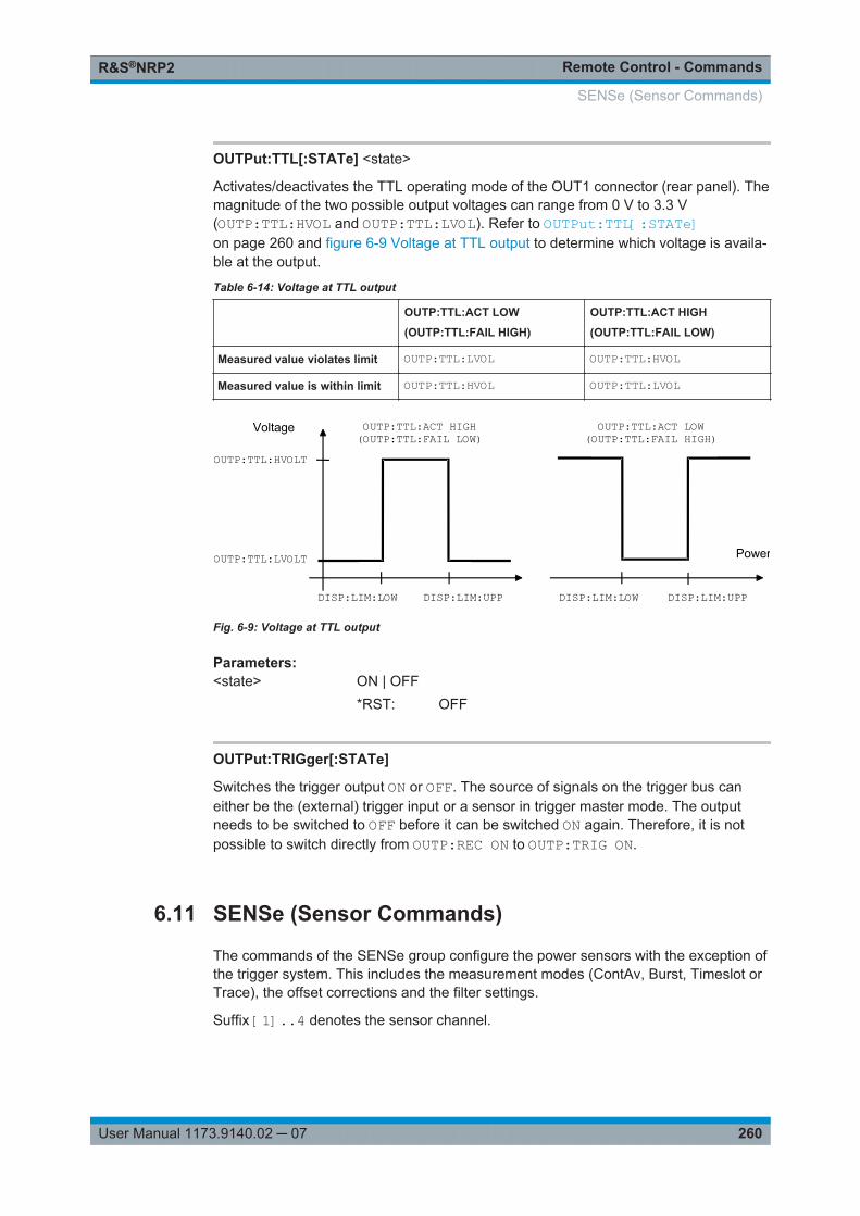
Remote Control - CommandsR&S®NRP2
260User Manual 1173.9140.02 ─ 07
OUTPut:TTL[:STATe] <state>
Activates/deactivates the TTL operating mode of the OUT1 connector (rear panel). Themagnitude of the two possible output voltages can range from 0 V to 3.3 V(OUTP:TTL:HVOL and OUTP:TTL:LVOL). Refer to OUTPut:TTL[:STATe]on page 260 and figure 6-9 Voltage at TTL output to determine which voltage is availa-ble at the output.
Table 6-14: Voltage at TTL output
OUTP:TTL:ACT LOW
(OUTP:TTL:FAIL HIGH)
OUTP:TTL:ACT HIGH
(OUTP:TTL:FAIL LOW)
Measured value violates limit OUTP:TTL:LVOL OUTP:TTL:HVOL
Measured value is within limit OUTP:TTL:HVOL OUTP:TTL:LVOL
Power
Voltage
OUTP:TTL:HVOLT
DISP:LIM:LOW DISP:LIM:UPP
OUTP:TTL:LVOLT
DISP:LIM:LOW DISP:LIM:UPP
OUTP:TTL:ACT HIGH(OUTP:TTL:FAIL LOW)
OUTP:TTL:ACT LOW(OUTP:TTL:FAIL HIGH)
Fig. 6-9: Voltage at TTL output
Parameters:<state> ON | OFF
*RST: OFF
OUTPut:TRIGger[:STATe]
Switches the trigger output ON or OFF. The source of signals on the trigger bus caneither be the (external) trigger input or a sensor in trigger master mode. The outputneeds to be switched to OFF before it can be switched ON again. Therefore, it is notpossible to switch directly from OUTP:REC ON to OUTP:TRIG ON.
6.11 SENSe (Sensor Commands)
The commands of the SENSe group configure the power sensors with the exception ofthe trigger system. This includes the measurement modes (ContAv, Burst, Timeslot orTrace), the offset corrections and the filter settings.
Suffix [1]..4 denotes the sensor channel.
SENSe (Sensor Commands)
Remote Control - CommandsR&S®NRP2
261User Manual 1173.9140.02 ─ 07
When the sensors are connected to the R&S NRP2, they inform the device about theSENSe and TRIGger commands supported and about the value ranges for parame-ters. This applies to both numeric and text parameters. For this reason, no fixed rangesare specified with these commands; the ranges can be obtained from the respectivesensor manual.
[SENSe<[1]..4>]:AUXiliary...............................................................................................263[SENSe<[1]..4>]:AVERage:COUNt.................................................................................. 263[SENSe<[1]..4>]:AVERage:COUNt:AUTO........................................................................ 264[SENSe<[1]..4>]:AVERage:COUNt:AUTO:MTIMe..............................................................264[SENSe<[1]..4>]:AVERage:COUNt:AUTO:RESolution....................................................... 264[SENSe<[1]..4>]:AVERage:COUNt:AUTO:SLOT............................................................... 265[SENSe<[1]..4>]:AVERage:COUNt:AUTO:NSRatio............................................................265[SENSe<[1]..4>]:AVERage:COUNt:AUTO:TYPE............................................................... 265[SENSe<[1]..4>]:AVERage:RESet................................................................................... 266[SENSe<[1]..4>]:AVERage[:STATe].................................................................................266[SENSe<[1]..4>]:AVERage:TCONtrol............................................................................... 266[SENSe<[1]..4>]:BANDwidth:VIDeo................................................................................. 266[SENSe<[1]..4>]:BWIDth:VIDeo.......................................................................................266[SENSe<[1]..4>]:BANDwidth:VIDeo:LIST?........................................................................267[SENSe<[1]..4>]:BWIDth:VIDeo:LIST?............................................................................. 267[SENSe<[1]..4>]:CORRection:OFFSet..............................................................................267[SENSe<[1]..4>]:CORRection:OFFSet:STATe...................................................................267[SENSe<[1]..4>]:CORRection:DCYCle[:INPut][:MAGNitude]...............................................267[SENSe<[1]..4>]:CORRection:DCYCle:STATe.................................................................. 268[SENSe<[1]..4>]:CORRection:FDOFfset[:INPut][:MAGNitude]?...........................................268[SENSe<[1]..4>]:CORRection:FDOTable[:SELect].............................................................268[SENSe<[1]..4>]:CORRection:FDOTable:STATe...............................................................268[SENSe<[1]..4>]:CORRection:SPDevice:SELect............................................................... 269[SENSe<[1]..4>]:CORRection:SPDevice:STATe................................................................269[SENSe<[1]..4>]:FREQuency[:CW].................................................................................. 269[SENSe<[1]..4>]:FREQuency[:FIXed]...............................................................................269[SENSe<[1]..4>]:FUNCtion[:ON]...................................................................................... 269[SENSe<[1]..4>][:POWer][:AVG]:APERture.......................................................................272[SENSe<[1]..4>][:POWer][:AVG]:BUFFer:SIZE..................................................................272[SENSe<[1]..4>][:POWer][:AVG]:BUFFer:STATe...............................................................272[SENSe<[1]..4>][:POWer][:AVG]:RANGe..........................................................................273[SENSe<[1]..4>][:POWer][:AVG]:RANGe:AUTO................................................................ 273[SENSe<[1]..4>][:POWer][:AVG]:RANGe:CLEVel.............................................................. 273[SENSe<[1]..4>][:POWer][:AVG]:SMOothing:STATe..........................................................273[SENSe<[1]..4>][:POWer]:BURSt:DTOLerance................................................................. 274[SENSe<[1]..4>][:POWer]:TGATe<[1]..4>[:EXCLude]:MID:OFFSet[:TIME] .......................... 274[SENSe<[1]..4>][:POWer]:TGATe[:EXCLude]:MID[:STATe]................................................ 275[SENSe<[1]..4>][:POWer]:TGATe<[1]..4>[:EXCLude]:MID:TIME......................................... 275[SENSe<[1]..4>][:POWer]:TGATe<[1]..4>:OFFSet:TIME.................................................... 275[SENSe<[1]..4>][:POWer]:TGATe:SELect.........................................................................276[SENSe<[1]..4>][:POWer]:TGATe<[1]..4>:TIME.................................................................276[SENSe<[1]..4>][:POWer]:TSLot:COUNt...........................................................................277[SENSe<[1]..4>][:POWer]:TSLot[:EXCLude]:MID:OFFSet[:TIME]........................................277
SENSe (Sensor Commands)
Remote Control - CommandsR&S®NRP2
262User Manual 1173.9140.02 ─ 07
[SENSe<[1]..4>][:POWer]:TSLot[:EXCLude]:MID[:STATe]..................................................277[SENSe<[1]..4>][:POWer]:TSLot[:EXCLude]:MID:TIME......................................................277[SENSe<[1]..4>][:POWer]:TSLot:[AVG]:WIDTh................................................................. 278[SENSe<[1]..4>]:RGAMma[:MAGNitude].......................................................................... 278[SENSe<[1]..4>]:RGAMma:PHASe.................................................................................. 279[SENSe<[1]..4>]:SAMPling..............................................................................................279[SENSe<[1]..4>]:SGAMma[:MAGNitude].......................................................................... 279[SENSe<[1]..4>]:SGAMma:PHASe.................................................................................. 279[SENSe<[1]..4>]:SGAMma:CORRection:STATe................................................................280[SENSe<[1]..4>]:STATistics:AVERage?............................................................................280[SENSe<[1]..4>]:STATistics[:EXCLude]:MID:OFFSet[:TIME].............................................. 280[SENSe<[1]..4>]:STATistics[:EXCLude]:MID:TIME............................................................ 280[SENSe<[1]..4>]:STATistics:PEAK?................................................................................. 281[SENSe<[1]..4>]:STATistics:OFFSet[:TIME]......................................................................281[SENSe<[1]..4>]:STATistics:SAMPles[:MINimum]..............................................................281[SENSe<[1]..4>]:STATistics:SCALe:X:MPWidth?.............................................................. 281[SENSe<[1]..4>]:STATistics:SCALe:X:POINts...................................................................282[SENSe<[1]..4>]:STATistics:SCALe:X:RANGe.................................................................. 282[SENSe<[1]..4>]:STATistics:SCALe:X:RLEVel.................................................................. 282[SENSe<[1]..4>]:STATistics:TIME....................................................................................283[SENSe<[1]..4>]:TIMing:EXCLude:STARt.........................................................................283[SENSe<[1]..4>]:TIMing:EXCLude:STOP..........................................................................283[SENSe<[1]..4>]:TRACe:AVERage[:STATe]..................................................................... 284[SENSe<[1]..4>]:TRACe:AVERage:COUNt.......................................................................284[SENSe<[1]..4>]:TRACe:AVERage:COUNt:AUTO.............................................................284[SENSe<[1]..4>]:TRACe:AVERage:COUNt:AUTO:MTIMe.................................................. 285[SENSe<[1]..4>]:TRACe:AVERage:COUNt:AUTO:RESolution............................................285[SENSe<[1]..4>]:TRACe:AVERage:COUNt:AUTO:POINt................................................... 286[SENSe<[1]..4>]:TRACe:AVERage:COUNt:AUTO:NSRatio................................................ 286[SENSe<[1]..4>]:TRACe:AVERage:COUNt:AUTO:TYPE....................................................286[SENSe<[1]..4>]:TRACe:AVERage:TCONtrol....................................................................287[SENSe<[1]..4>]:TRACe:MEASurement:ALGorithm...........................................................287[SENSe<[1]..4>]:TRACe:MEASurement:AUTO[:STATe].....................................................287[SENSe<[1]..4>]:TRACe:MEASurement:DEFine:DURation:REFerence............................... 288[SENSe<[1]..4>]:TRACe:MEASurement:DEFine:TRANsition:HREFerence...........................288[SENSe<[1]..4>]:TRACe:MEASurement:DEFine:TRANsition:LREFerence........................... 288[SENSe<[1]..4>]:TRACe:MEASurement:POWer:AVG?...................................................... 288[SENSe<[1]..4>]:TRACe:MEASurement:POWer:MAX?...................................................... 289[SENSe<[1]..4>]:TRACe:MEASurement:POWer:MIN?....................................................... 289[SENSe<[1]..4>]:TRACe:MEASurement:POWer:PULSe:BASE?......................................... 289[SENSe<[1]..4>]:TRACe:MEASurement:POWer:PULSe:TOP?........................................... 289[SENSe<[1]..4>]:TRACe:MEASurement:PULSe:DCYCle?..................................................289[SENSe<[1]..4>]:TRACe:MEASurement:PULSe:DURation?............................................... 289[SENSe<[1]..4>]:TRACe:MEASurement:PULSe:PERiod?...................................................289[SENSe<[1]..4>]:TRACe:MEASurement:PULSe:SEParation?............................................. 290[SENSe<[1]..4>]:TRACe:MEASurement:TRANSition:ESAMpling:AUTO[:STATe]?................ 290[SENSe<[1]..4>]:TRACe:MEASurement:TRANSition:NEGative:DURation?.......................... 290[SENSe<[1]..4>]:TRACe:MEASurement:TRANSition:NEGative:OCCurrence?......................290[SENSe<[1]..4>]:TRACe:MEASurement:TRANSition:NEGative:OVERshoot?....................... 290[SENSe<[1]..4>]:TRACe:MEASurement:TRANSition:POSitive:DURation?........................... 291
SENSe (Sensor Commands)
Remote Control - CommandsR&S®NRP2
263User Manual 1173.9140.02 ─ 07
[SENSe<[1]..4>]:TRACe:MEASurement:TRANSition:POSitive:OCCurrence?....................... 291[SENSe<[1]..4>]:TRACe:MEASurement:TRANSition:POSitive:OVERshoot?........................ 291[SENSe<[1]..4>]:TRACe:MEASurement:TRANSition:SPERiod?..........................................291[SENSe<[1]..4>]:TRACe:MEASurement[:STATe]...............................................................291[SENSe<[1]..4>]:TRACe:MID:OFFSet:TIME......................................................................292[SENSe<[1]..4>]:TRACe:MID:TIME..................................................................................292[SENSe<[1]..4>]:TRACe:OFFSet:TIME............................................................................ 292[SENSe<[1]..4>]:TRACe:POINts......................................................................................292[SENSe<[1]..4>]:TRACe:REALtime..................................................................................293[SENSe<[1]..4>]:TRACe:TIME.........................................................................................293
[SENSe<[1]..4>]:AUXiliary <mode>
Activates the measurement of additional measured values that are determinedtogether with the main measured value.
Parameters:<mode> NONE
No additional values are measured.MINMaxBy averaging the measured values in the sensors, extreme val-ues are lost. Using [SENSe<[1]..4>]:AUXiliary MINMax ,a sensor can be assigned to transmit to the R&S NRP2 the min-ima and maxima that occurred in the Trace mode together withthe measured value. If CALCulate:FEED "POWer:PEAK ONSWEep<[1]..4>" is set, peak (instead of average) values areused for calculating.RNDMaxIn contrast to MINMax, instead of the Min value the value of arandomly selected sample is returned. All evaluations occurusing these values instead of the average values.*RST: depending on sensor
[SENSe<[1]..4>]:AVERage:COUNt <filter_length>
Sets the filter length i.e. the number of readings to be averaged for one measuredvalue.. The higher the count the lower the noise and the longer it takes to obtain ameasured value.
Parameters:<filter_length> int_value
Range: depending on sensor*RST: depending on sensorDefault unit: -
SENSe (Sensor Commands)
Remote Control - CommandsR&S®NRP2
264User Manual 1173.9140.02 ─ 07
[SENSe<[1]..4>]:AVERage:COUNt:AUTO <state>
Can be used to automatically determine a value for the filter legth[SENSe<[1]..4>]:AVERage:COUNt. If the automatic switchover is activated withthe ON parameter, the sensor always defines a suitable filter length which can also bequeried via SENS<[1]..4>:AVER:COUN?.
Parameters:<state> ON | OFF | ONCE
ONActivates automatic switchover. The sensor always defines asuitable filter length which can also be queried viaSENS<[1]..4>:AVER:COUN?OFFDeactivates automatic switchover.ONCEThe filter length is automatically detected during the next mea-surement and set to that value. Thereafter automatic filter lengthdetection is switched off. The setting can then be queried viaSENS<[1]..4>:AVER:COUN?*RST: depending on sensor
[SENSe<[1]..4>]:AVERage:COUNt:AUTO:MTIMe <mtime>
If the R&S NRP2 has to determine the filter length automatically, the filter length canbecome large and thus also the measurement time.
An upper time limit can be set via SENS<[1]..4>:AVER:COUN:AUTO:MTIME (maxi-mum time). It should never be exceeded. Undesired long measurement times can thusbe prevented (in the SENS:AVER:COUN:AUTO:TYPE NSR mode) if the automatic filterlength switchover is on.
Parameters:<mtime> float_value, measurement time
Range: depending on sensor*RST: depending on sensorDefault unit: S
[SENSe<[1]..4>]:AVERage:COUNt:AUTO:RESolution <resolution>
Defines the number of significant places for linear units and the number of decimal pla-ces for logarithmic units which should be free of noise in the measurement result. Thissetting is also performed by the command DISPlay[:WINDow]<[1]..4>:RESolution on page 245 that tries to set the sensors involved in the measurementresults accordingly. For further details, see chapter 4, "Instrument Functions",on page 61.
The setting is only taken into account, if SENS:AVER:COUN:AUTO:TYPE is set to RESand SENS:AVER:COUN:AUTO is ON.
SENSe (Sensor Commands)

Remote Control - CommandsR&S®NRP2
265User Manual 1173.9140.02 ─ 07
However, SENS<[1]..4>:AVER:COUN:AUTO:RES does not affect the DISPlaycommand. The parameters of the two commands are different but have the samemeaning.
SENS<[1]..4>:AVER:COUN:AUTO:RES 1 2 3 4
DISP<[1]..4>:RES 1 0.1 0.01 0.001
Parameters:<<resolution>> 1 | 2 | 3 | 4
Range: depending on sensor*RST: depending on sensor
[SENSe<[1]..4>]:AVERage:COUNt:AUTO:SLOT <slot>
Sets a timeslot whose measured value is used to automatically determine the filterlength.
Parameters:<slot> int_value
Range: depending on sensor*RST: depending on sensor
[SENSe<[1]..4>]:AVERage:COUNt:AUTO:NSRatio <nsratio>
Indicates the maximum noise ratio in the measurement result. Achieving the sameresult by filter length setting is attempted only if
SENS<[1]..4>:AVER:COUN:AUTO ON andSENS<[1]..4>:AVER:COUN:AUTO:TYPE NSR are set.
Unit: DB | PCT
Parameters:<nsratio> float_value
Range: depending on sensor*RST: depending on sensorDefault unit: DB
[SENSe<[1]..4>]:AVERage:COUNt:AUTO:TYPE <mode>
Selects a method by which the automatic filter length switchover can operate:
SENSe (Sensor Commands)
Remote Control - CommandsR&S®NRP2
266User Manual 1173.9140.02 ─ 07
Parameters:<mode> RESolution
takes setting SENS<[1]..4>:AVER:COUN:AUTO:RES intoaccount.NSRtakes setting SENS<[1]..4>:AVER:COUN:AUTO:NSR intoaccount.*RST: depending on sensor
[SENSe<[1]..4>]:AVERage:RESet
Initializes the digital filter by deleting the stored measured values.
Usage: Event
[SENSe<[1]..4>]:AVERage[:STATe] <state>
Activates or deactivates the filter function of a sensor. If the filter is switched on, theindividual measured values set with SENSe<[1]..4>]:AVERage:COUNt are aver-aged. This reduces the impact of noise and helps to achieve measured values that aremore stable.
Parameters:<state> ON | OFF
*RST: depending on sensor
[SENSe<[1]..4>]:AVERage:TCONtrol <mode>
As soon as a new single value is determined, the filter window is advanced by onevalue so that the new value is taken into account by the filter and the oldest value isforgotten. [SENSe<[1]..4>]:AVERage:TCONtrol (terminal control) then deter-mines whether a new result is calculated immediately after a new measured value isavailable (MOVing) or only after an entire range of new values is available for the filter(REPeat).
Note:
In the MOVing mode, data from a point of time before the start of the current measure-ment can influence the measurement result if the data is still in the filter.
Parameters:<mode> MOVing | REPeat
*RST: REPeat; (PRES) and SYST:PRES: MOVing
[SENSe<[1]..4>]:BANDwidth:VIDeo <bandwidth>[SENSe<[1]..4>]:BWIDth:VIDeo <bandwidth>
Sets the video bandwidth for the Trace mode.
SENSe (Sensor Commands)
Remote Control - CommandsR&S®NRP2
267User Manual 1173.9140.02 ─ 07
Parameters:<bandwidth> string
Range: "FULL", "5 MHz", "1.5 MHz", "300 kHz"*RST: depending on sensor
[SENSe<[1]..4>]:BANDwidth:VIDeo:LIST?[SENSe<[1]..4>]:BWIDth:VIDeo:LIST?Provides a list of strings with permissible settings forthe[SENSe<[1]..4>]:BWIDth:VIDeo command. Lists are not affected by the *RSTcommand.
Usage: Query only
[SENSe<[1]..4>]:CORRection:OFFSet <offset_value>
A fixed offset value can be defined for multiplying (logarithmically adding) the mea-sured value of a sensor. If the parameters are specified without a unit, the unit set byUNIT:POW:RAT will be used.
Unit: DB | PCT
Parameters:<offset_value> float_value
Range: depending on sensor*RST: depending on sensorDefault unit: DB
[SENSe<[1]..4>]:CORRection:OFFSet:STATe <state>
Switches the offset correction on or off.
Parameters:<state> ON | OFF
*RST: depending on sensor
[SENSe<[1]..4>]:CORRection:DCYCle[:INPut][:MAGNitude] <magnitude>
Informs the R&S NRP2 about the duty cycle of the power to be measured. The dutycycle correction is only applied in the ContAv mode where measurements are per-formed continuously without taking the timing of the signal into account.
Parameters:<magnitude> float_value
Range: depending on sensor*RST: depending on sensorDefault unit: PCT
SENSe (Sensor Commands)
Remote Control - CommandsR&S®NRP2
268User Manual 1173.9140.02 ─ 07
[SENSe<[1]..4>]:CORRection:DCYCle:STATe <state>
Switches duty cycle correction for the measured-value on or off.
Parameters:<state> ON | OFF
*RST: depending on sensor
[SENSe<[1]..4>]:CORRection:FDOFfset[:INPut][:MAGNitude]?
Queries the frequency dependent offset. The frequency-dependent measured-valuecorrection is set by selecting a table with the[SENSe<[1]..4>]:CORRection:FDOTable[:SELect] and[SENSe<[1]..4>]:CORRection:FDOTable:STATe ON commands. The respec-tive frequency-dependent correction factor is determined by means of the active tables(if necessary by interpolation) and can be queried with[SENSe<[1]..4>]:CORRection:FDOFfset[:INPut][:MAGNitude]? (fre-quency-dependent offset).
Unit: DB
Usage: Query only
[SENSe<[1]..4>]:CORRection:FDOTable[:SELect] <table_name>
The name of the current frequency-dependent offset table can be set or queried by the[SENSe<[1]..4>]:CORRection:FDOTable[:SELect][?] command. TheR&S NRP2 can manage up to ten tables (MEMory commands). The frequency-dependent offset tables consist of two columns; the first containing the frequencies, thesecond the associated correction values. When the R&S NRP2 is informed about thesignal frequency with command [SENSe<[1]..4>]:FREQuency[:CW|:FIXed]<float_value>, an appropriate correction factor is determined by means of thetable. If the table was activated with[SENSe<[1]..4>]:CORRection:FDOTable:STATe[?] ON , the measurementresult obtained by the sensor is multiplied by this factor.
Error messages:
-256 "File name not found": An invalid <string> parameter was transmitted.
Parameters:<table_name> string
*RST: Settings are not changed in case of *RST.
[SENSe<[1]..4>]:CORRection:FDOTable:STATe <state>
Activates and deactivates the current frequency-dependent offset table. The currenttable is selected with the [SENSe<[1]..4>]:CORRection:FDOTable[:SELect]command. Only one table can be active at a time.
SENSe (Sensor Commands)
Remote Control - CommandsR&S®NRP2
269User Manual 1173.9140.02 ─ 07
Parameters:<state> ON | OFF
*RST: OFF
[SENSe<[1]..4>]:CORRection:SPDevice:SELect <NR1>
Several S-parameter tables can be stored in a sensor.
[SENSe<[1]..4>]:CORRection:SPDevice:SELect selects one of these tables.The [SENSe<[1]..4>]:CORRection:SPDevice:STATe ON command activatesmeasured-value correction.
Parameters:<NR1> int_value
*RST: depending on sensor
[SENSe<[1]..4>]:CORRection:SPDevice:STATe <state>
Instructs the sensor to perform a measured-value correction by means of one of thestored S-parameter tables (S-parameter device).
Parameters:<state> ON | OFF
*RST: depending on sensor
[SENSe<[1]..4>]:FREQuency[:CW] <frequency>[SENSe<[1]..4>]:FREQuency[:FIXed] <frequency>
Informs the R&S NRP2 about the frequency of the power to be measured since thisfrequency is not automatically determined. The frequency is used to determine a fre-quency-dependent correction factor for the measurement results.
Parameters:<frequency> float_value
Range: depending on sensor*RST: depending on sensorDefault unit: HZ
[SENSe<[1]..4>]:FUNCtion[:ON] <mode>
Sets the sensor to the selected measurement mode.
In remote control, the timing (SENS:TIM:EXCL:STAR and -:STOP) and the triggersystem of all measurement modes (except the Burst mode) are user-selectable.
Note:
SENSe (Sensor Commands)
Remote Control - CommandsR&S®NRP2
270User Manual 1173.9140.02 ─ 07
To increase measurement accuracy, the sensors measure each signal twice in theBurst, Timeslot and Trace measurement modes (exception: in the Trace mode, withSENS:TRAC:REAL ON). As long as the trigger system is set to internal or external trig-gering, this is usually of no importance to the user. If TRIG:SOUR HOLD or BUS isused, however, then each measurement must be triggered twice (with *TRG orTRIG:IMM).
Error messages:
24 "Sensor mode not supported": A sensor does not support a measurement mode.
28 "Sensor not idle": The sensor is not in the IDLE state.
-151 "Invalid string data": An invalid parameter was transmitted for <string>.
SENSe (Sensor Commands)
Remote Control - CommandsR&S®NRP2
271User Manual 1173.9140.02 ─ 07
Parameters:<mode> string
"POWer:AVG"ContAvAfter a trigger event, the power is integrated over a time interval(averaging) set with SENS:POW:APER.
"POWer:TSLot:AVG"TimeslotThe power is simultaneously measured in up to 26 time win-dows. The number of time windows is set withSENS:POW:TSL:COUN. The length of a time window is deter-mined via SENS:POW:TSL:WIDT. The measurement result isrepresented by a vector that can contain up to 26 indices andcontains the power of a time window at each index."POWer:TGATe:AVG"TimegateThe Timegate mode is a pseudo-mode. It is used to determineaccurate measured values in the gates defined with the aid ofthe Trace mode in manual operation. If one of the four gates isselected (SENS:TRAC:SEL), the sensor is internally put into theTimeslot mode and configured such that it determines the aver-age power in this gate with high accuracy."POWer:BURSt:AVG"BurstIn remote control, this measurement mode is very similar to theContAv mode. The integration time is, however, not predefinedbut determined by the sensor with the aid of a burst detector.The start of a burst is detected when the measurement signalrises above the set trigger level. The end is set when the signaldrops below the trigger threshold. SENS:POW:BURS:DTOLdefines the time interval during which a signal drop below thetrigger level is not interpreted as the end of the burst. In theBurst mode, the set trigger source is ignored and TRIG:SOURINT is implicitly assumed.
"XPOWer:CCDF"CCDFThe power in a settable time interval is measured and subse-quently subjected to a statistical evaluation (CCDF). The mea-surement time is set using the SENS:STAT commands. TheR&S NRP2 returns in response to READ? or FETCh? an array ofdensity values which are spread over the power axis. The valuerange of the power axis is also set using theSENS:STAT:SCAL:X commands.CDFThe CDF does not represent a separate mode in the sensor. It iscalculated in the R&S NRP2 by way of the relationCDF = 1-CCDF."XPOWer:PDF"
SENSe (Sensor Commands)

Remote Control - CommandsR&S®NRP2
272User Manual 1173.9140.02 ─ 07
Like "XPOWer:CCDF", except that a PDF is calculated insteadof a CCDF."XTIMe:POWer"A sequence of measurements is performed. The individual mea-sured values are determined as in the ContAv mode. The lengthof an individual measurement is determined from the ratio of thetotal time (SENS:TRAC:TIME) and the number of individual testpoints (SENS:TRAC:POIN).
*RST: depending on sensor
[SENSe<[1]..4>][:POWer][:AVG]:APERture <integration_time>
Determines the integration time for a single measurement in the ContAv mode. Toincrease the measurement accuracy, this integration is followed by a second averagingprocedure in a window with a selectable number of values. The filter window is config-ured with the [SENSe<[1]..4>]:AVERage commands.
Parameters:<integration_time> float_value
Range: depending on sensor*RST: depending on sensorDefault unit: S
[SENSe<[1]..4>][:POWer][:AVG]:BUFFer:SIZE <number>
Sets the number of desired values for the buffered ContAv mode.
Parameters:<number> int_value
Range: 1...400000*RST: depending on sensor
[SENSe<[1]..4>][:POWer][:AVG]:BUFFer:STATe <state>
Switches on the buffered ContAv mode, after which data blocks rather than singlemeasured values are then returned. In this mode a higher data rate is achieved than inthe non-buffered ContAv mode.
The number of desired measured values is set with theSENSe<[1]..4>:POWer:ARR:SIZE command.
Parameters:<state> ON | OFF
*RST: depending on sensor
SENSe (Sensor Commands)
Remote Control - CommandsR&S®NRP2
273User Manual 1173.9140.02 ─ 07
[SENSe<[1]..4>][:POWer][:AVG]:RANGe <range>
Selects a measurement range in which the corresponding sensor is to perform a mea-surement. This setting will only become effective if SENS<[1]..4>:RANG:AUTO OFFis set.
Parameters:<range> 0 | 1 | 2
*RST: depending on sensor
[SENSe<[1]..4>][:POWer][:AVG]:RANGe:AUTO <state>
Activates/deactivates the automatic selection of a measurement range.
Parameters:<state> ON | OFF
*RST: depending on sensor
[SENSe<[1]..4>][:POWer][:AVG]:RANGe:CLEVel <level>
Sets the cross-over level. Shifts the transition ranges between the measurementranges. This may improve the measurement accuracy for special signals, i.e. signalswith a high crest factor.
Unit: DB | PCT
Parameters:<clevel> float_value
Range: depending on sensor*RST: depending on sensorDefault unit: DB
[SENSe<[1]..4>][:POWer][:AVG]:SMOothing:STATe <state>
Activates/deactivates digital lowpass filtering of the sampled video signal.
The problem of instable display values due to a modulation of a test signal describedunder SENS<[1]..4>:SAMP can also be eliminated by lowpass filtering of the videosignal. The lowpass filter eliminates the variations of the display even in case of unperi-odic modulation and does not require any other setting.
If modulation is periodic, setting the aperture time is the better method, since it allowsshorter measurement times.
Parameters:<state> ON | OFF
*RST: depending on sensor
SENSe (Sensor Commands)
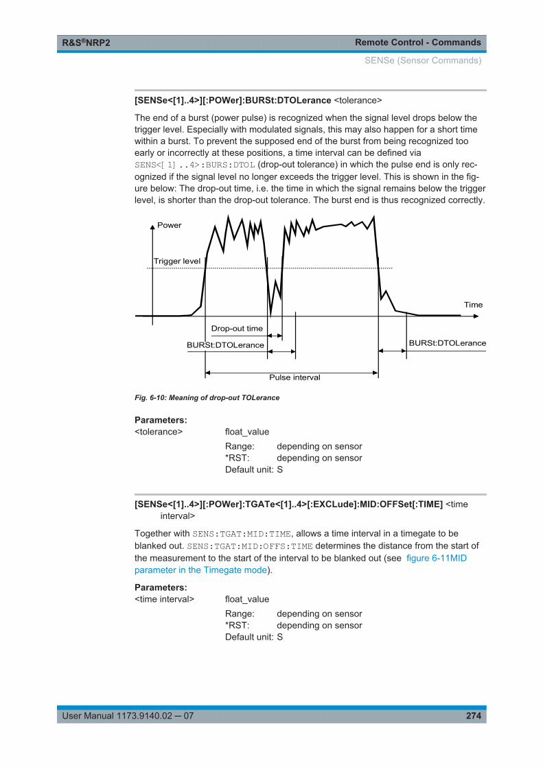
Remote Control - CommandsR&S®NRP2
274User Manual 1173.9140.02 ─ 07
[SENSe<[1]..4>][:POWer]:BURSt:DTOLerance <tolerance>
The end of a burst (power pulse) is recognized when the signal level drops below thetrigger level. Especially with modulated signals, this may also happen for a short timewithin a burst. To prevent the supposed end of the burst from being recognized tooearly or incorrectly at these positions, a time interval can be defined viaSENS<[1]..4>:BURS:DTOL (drop-out tolerance) in which the pulse end is only rec-ognized if the signal level no longer exceeds the trigger level. This is shown in the fig-ure below: The drop-out time, i.e. the time in which the signal remains below the triggerlevel, is shorter than the drop-out tolerance. The burst end is thus recognized correctly.
Drop-out time
Trigger level
Power
Time
BURSt:DTOLerance
Pulse interval
BURSt:DTOLerance
Fig. 6-10: Meaning of drop-out TOLerance
Parameters:<tolerance> float_value
Range: depending on sensor*RST: depending on sensorDefault unit: S
[SENSe<[1]..4>][:POWer]:TGATe<[1]..4>[:EXCLude]:MID:OFFSet[:TIME] <timeinterval>
Together with SENS:TGAT:MID:TIME, allows a time interval in a timegate to beblanked out. SENS:TGAT:MID:OFFS:TIME determines the distance from the start ofthe measurement to the start of the interval to be blanked out (see figure 6-11MIDparameter in the Timegate mode).
Parameters:<time interval> float_value
Range: depending on sensor*RST: depending on sensorDefault unit: S
SENSe (Sensor Commands)
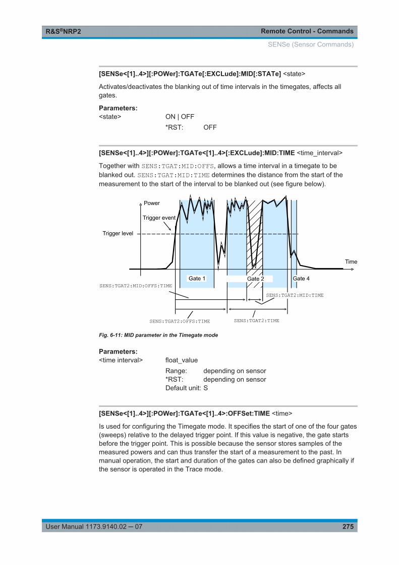
Remote Control - CommandsR&S®NRP2
275User Manual 1173.9140.02 ─ 07
[SENSe<[1]..4>][:POWer]:TGATe[:EXCLude]:MID[:STATe] <state>
Activates/deactivates the blanking out of time intervals in the timegates, affects allgates.
Parameters:<state> ON | OFF
*RST: OFF
[SENSe<[1]..4>][:POWer]:TGATe<[1]..4>[:EXCLude]:MID:TIME <time_interval>
Together with SENS:TGAT:MID:OFFS, allows a time interval in a timegate to beblanked out. SENS:TGAT:MID:TIME determines the distance from the start of themeasurement to the start of the interval to be blanked out (see figure below).
Trigger level
Power
Time
Trigger event
Gate 4
SENS:TGAT2:OFFS:TIME SENS:TGAT2:TIME
SENS:TGAT2:MID:TIMESENS:TGAT2:MID:OFFS:TIME
Fig. 6-11: MID parameter in the Timegate mode
Parameters:<time interval> float_value
Range: depending on sensor*RST: depending on sensorDefault unit: S
[SENSe<[1]..4>][:POWer]:TGATe<[1]..4>:OFFSet:TIME <time>
Is used for configuring the Timegate mode. It specifies the start of one of the four gates(sweeps) relative to the delayed trigger point. If this value is negative, the gate startsbefore the trigger point. This is possible because the sensor stores samples of themeasured powers and can thus transfer the start of a measurement to the past. Inmanual operation, the start and duration of the gates can also be defined graphically ifthe sensor is operated in the Trace mode.
SENSe (Sensor Commands)
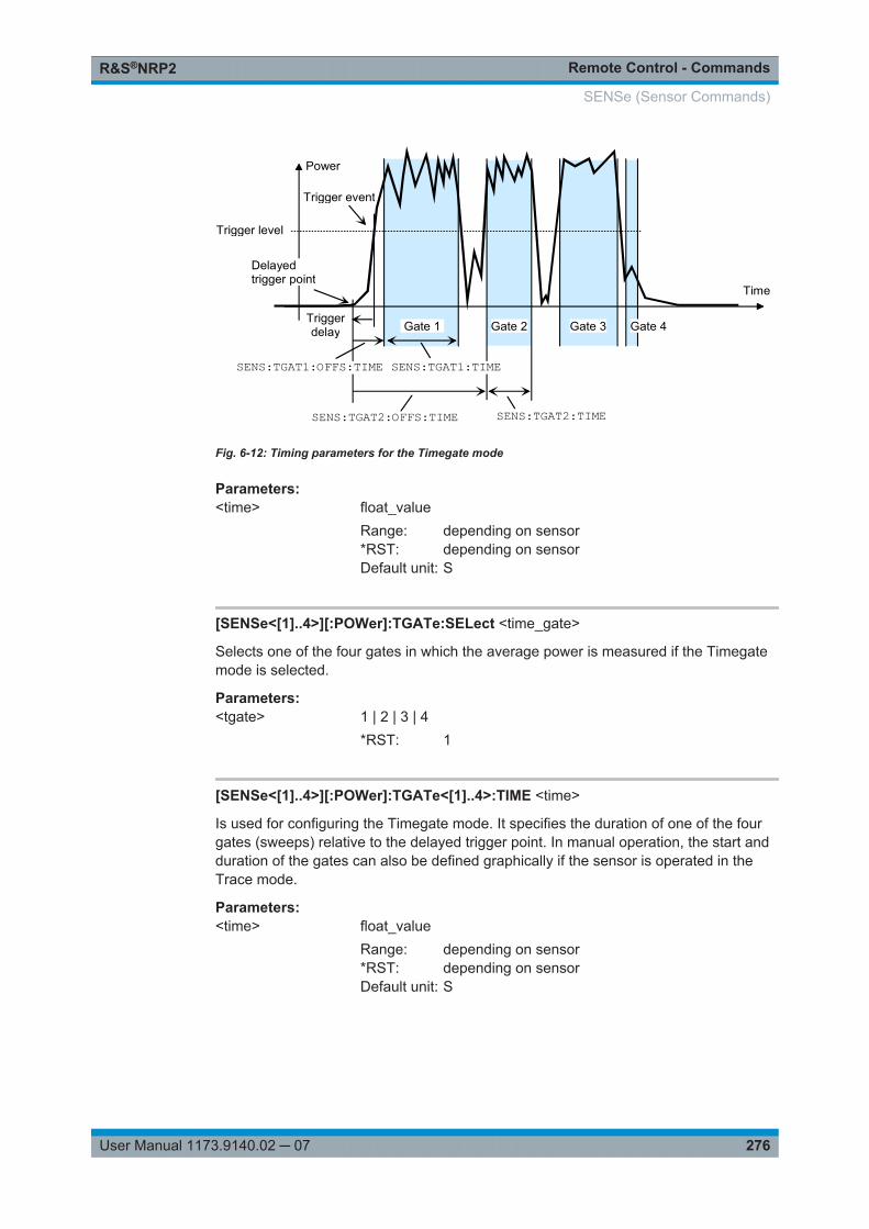
Remote Control - CommandsR&S®NRP2
276User Manual 1173.9140.02 ─ 07
Trigger level
Power
Time
Trigger event
Delayed trigger point
Trigger delay Gate 1 Gate 4 Gate 3 Gate 2
SENS:TGAT1:OFFS:TIME SENS:TGAT1:TIME
SENS:TGAT2:OFFS:TIME SENS:TGAT2:TIME
Fig. 6-12: Timing parameters for the Timegate mode
Parameters:<time> float_value
Range: depending on sensor*RST: depending on sensorDefault unit: S
[SENSe<[1]..4>][:POWer]:TGATe:SELect <time_gate>
Selects one of the four gates in which the average power is measured if the Timegatemode is selected.
Parameters:<tgate> 1 | 2 | 3 | 4
*RST: 1
[SENSe<[1]..4>][:POWer]:TGATe<[1]..4>:TIME <time>
Is used for configuring the Timegate mode. It specifies the duration of one of the fourgates (sweeps) relative to the delayed trigger point. In manual operation, the start andduration of the gates can also be defined graphically if the sensor is operated in theTrace mode.
Parameters:<time> float_value
Range: depending on sensor*RST: depending on sensorDefault unit: S
SENSe (Sensor Commands)
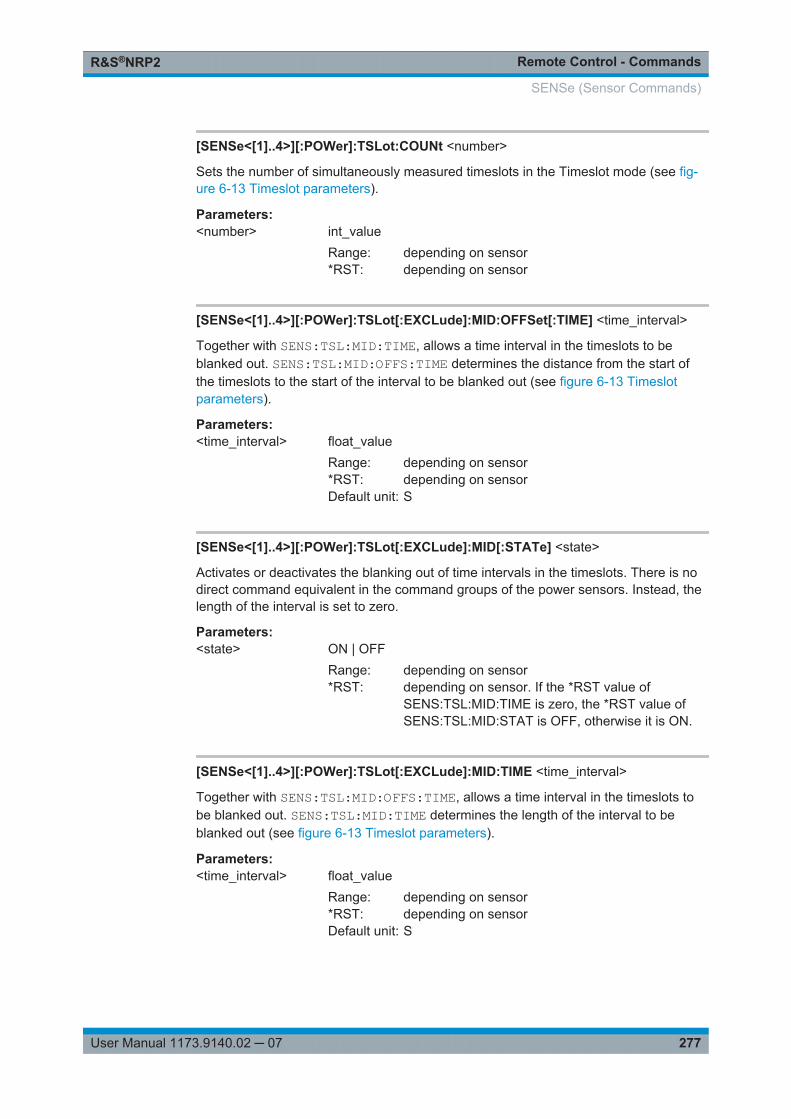
Remote Control - CommandsR&S®NRP2
277User Manual 1173.9140.02 ─ 07
[SENSe<[1]..4>][:POWer]:TSLot:COUNt <number>
Sets the number of simultaneously measured timeslots in the Timeslot mode (see fig-ure 6-13 Timeslot parameters).
Parameters:<number> int_value
Range: depending on sensor*RST: depending on sensor
[SENSe<[1]..4>][:POWer]:TSLot[:EXCLude]:MID:OFFSet[:TIME] <time_interval>
Together with SENS:TSL:MID:TIME, allows a time interval in the timeslots to beblanked out. SENS:TSL:MID:OFFS:TIME determines the distance from the start ofthe timeslots to the start of the interval to be blanked out (see figure 6-13 Timeslotparameters).
Parameters:<time_interval> float_value
Range: depending on sensor*RST: depending on sensorDefault unit: S
[SENSe<[1]..4>][:POWer]:TSLot[:EXCLude]:MID[:STATe] <state>
Activates or deactivates the blanking out of time intervals in the timeslots. There is nodirect command equivalent in the command groups of the power sensors. Instead, thelength of the interval is set to zero.
Parameters:<state> ON | OFF
Range: depending on sensor*RST: depending on sensor. If the *RST value of
SENS:TSL:MID:TIME is zero, the *RST value ofSENS:TSL:MID:STAT is OFF, otherwise it is ON.
[SENSe<[1]..4>][:POWer]:TSLot[:EXCLude]:MID:TIME <time_interval>
Together with SENS:TSL:MID:OFFS:TIME, allows a time interval in the timeslots tobe blanked out. SENS:TSL:MID:TIME determines the length of the interval to beblanked out (see figure 6-13 Timeslot parameters).
Parameters:<time_interval> float_value
Range: depending on sensor*RST: depending on sensorDefault unit: S
SENSe (Sensor Commands)
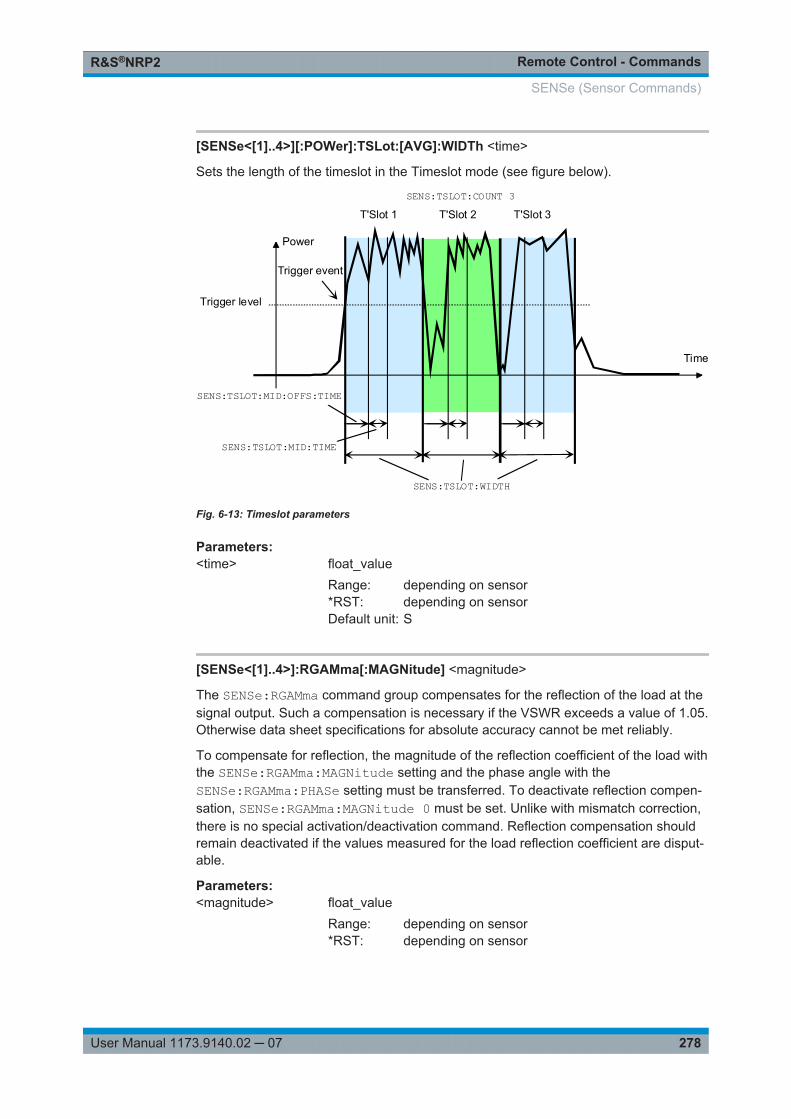
Remote Control - CommandsR&S®NRP2
278User Manual 1173.9140.02 ─ 07
[SENSe<[1]..4>][:POWer]:TSLot:[AVG]:WIDTh <time>
Sets the length of the timeslot in the Timeslot mode (see figure below).
Trigger level
Power
Time
Trigger event
SENS:TSLOT:WIDTH
SENS:TSLOT:MID:OFFS:TIME
SENS:TSLOT:MID:TIME
T'Slot 1 T'Slot 2 T'Slot 3
SENS:TSLOT:COUNT 3
Fig. 6-13: Timeslot parameters
Parameters:<time> float_value
Range: depending on sensor*RST: depending on sensorDefault unit: S
[SENSe<[1]..4>]:RGAMma[:MAGNitude] <magnitude>
The SENSe:RGAMma command group compensates for the reflection of the load at thesignal output. Such a compensation is necessary if the VSWR exceeds a value of 1.05.Otherwise data sheet specifications for absolute accuracy cannot be met reliably.
To compensate for reflection, the magnitude of the reflection coefficient of the load withthe SENSe:RGAMma:MAGNitude setting and the phase angle with theSENSe:RGAMma:PHASe setting must be transferred. To deactivate reflection compen-sation, SENSe:RGAMma:MAGNitude 0 must be set. Unlike with mismatch correction,there is no special activation/deactivation command. Reflection compensation shouldremain deactivated if the values measured for the load reflection coefficient are disput-able.
Parameters:<magnitude> float_value
Range: depending on sensor*RST: depending on sensor
SENSe (Sensor Commands)
Remote Control - CommandsR&S®NRP2
279User Manual 1173.9140.02 ─ 07
[SENSe<[1]..4>]:RGAMma:PHASe <phase_angle>
SENSe:RGAMma:PHASe defines the phase angle (in degrees) of the complex reflectionfactor of the load at the signal output.
Parameters:<phase_angle> float_value
Range: depending on sensor*RST: depending on sensorDefault unit: only the unit degree is accepted
[SENSe<[1]..4>]:SAMPling <sampling_rate>
If the signal to be measured has modulation sections just above the video bandwidth ofthe sensor used, measurement errors might be caused due to aliasing effects. In thiscase, the sampling rate of the sensor can be set to a safe lower value (FREQ2). How-ever, the measurement time required to obtain noise-free results is extended com-pared to the normal sampling rate (FREQ1).
Parameters:<sampling_rate> FREQ1 | FREQ2
*RST: depending on sensor
[SENSe<[1]..4>]:SGAMma[:MAGNitude] <magnitude>
The R&S NRP2 can perform a measured-value correction taking the complex reflectioncoefficient (source gamma) of the signal source into account.SENS<[1]..4>:SGAM:CORR:STAT ON must be set. The magnitude of the reflectioncoefficient is set with SENS<[1]..4>:SGAM[:MAGN].
Parameters:<magnitude> float_value
Range: depending on sensor*RST: depending on sensor
[SENSe<[1]..4>]:SGAMma:PHASe <phase>
The R&S NRP2 can perform a measured-value correction taking the complex reflectioncoefficient (source gamma) of the signal source into account.SENS<[1]..4>:SGAM:CORR:STAT ON must be set. The phase angle of the reflec-tion coefficient is set with SENS<[1]..4>:SGAM:PHAS.
Parameters:<phase> float_value
Range: depending on sensor*RST: depending on sensorDefault unit: degree
SENSe (Sensor Commands)
Remote Control - CommandsR&S®NRP2
280User Manual 1173.9140.02 ─ 07
[SENSe<[1]..4>]:SGAMma:CORRection:STATe <state>
Activates/deactivates the measured-value correction of the reflection coefficient effectof the source gamma.
Parameters:<state> ON | OFF
*RST: depending on sensor
Usage: Setting only
[SENSe<[1]..4>]:STATistics:AVERage? <power_value>
Returns the average power value calculated during a statistics measurement (CCDF/PDF).
Unit: DBM | W | DBUV
Parameters:<power_value> float_value
Default unit: DBM
Usage: Query only
[SENSe<[1]..4>]:STATistics[:EXCLude]:MID:OFFSet[:TIME] <time_interval>
Together with SENS:STAT:MID:TIME, allows a time interval within the time window tobe blanked out; in this interval, the data for the statistics is collected.SENS:STAT:MID:OFFS determines the distance from the start of the measurement tothe start of the interval to be blanked out (see also [SENSe<[1]..4>][:POWer]:TGATe<[1]..4>[:EXCLude]:MID:OFFSet[:TIME] on page 274).
Parameters:<time_interval> float_value
Range: depending on sensor*RST: depending on sensorDefault unit: S
[SENSe<[1]..4>]:STATistics[:EXCLude]:MID:TIME <time_interval>
Together with SENS:STAT:MID:OFFS, allows a time interval within the time window tobe blanked out; in this interval, the data for the statistics is collected.SENS:STAT:MID:TIME determines the length of the interval to be blanked out (seealso [SENSe<[1]..4>][:POWer]:TGATe<[1]..4>[:EXCLude]:MID:TIMEon page 275).
Parameters:<time_interval> float_value
Range: depending on sensor*RST: depending on sensorDefault unit: S
SENSe (Sensor Commands)
Remote Control - CommandsR&S®NRP2
281User Manual 1173.9140.02 ─ 07
[SENSe<[1]..4>]:STATistics:PEAK?
Returns the peak power value calculated during a statistics measurement (CCDF/PDF).
Usage: Query only
[SENSe<[1]..4>]:STATistics:OFFSet[:TIME] <time_interval>
Determines, together with the SENS:STAT:TIME command, the time interval in whichthe power for the statistical evaluation is measured. SENS:STAT:OFFS determines thestart of the interval relative to the (possibly delayed) trigger time (see also[SENSe<[1]..4>][:POWer]:TGATe<[1]..4>:OFFSet:TIME on page 275).
Parameters:<time_interval> float_value
Range: depending on sensor*RST: depending on sensorDefault unit: S
[SENSe<[1]..4>]:STATistics:SAMPles[:MINimum] <minimum>
Determines the minimum number of samples to be included in the statistics. For thispurpose, the filter length (which can only be set in powers of 2) is set such that the fol-lowing inequality applies:
dtmpwN
N MinSamplesfil
In this inequality, Nfil is the filter length (SENS:TRAC:AVER:COUN), mpw the time widthof a sample and dt the length of the window in which the measurement is performed(SENS:STAT:TIME).
Parameters:<minimum> int_value
*RST: 1e6
[SENSe<[1]..4>]:STATistics:SCALe:X:MPWidth?
Returns the minimum width of a sample on the power axis.
Parameters:<mpwidth> float_value
Usage: Query only
SENSe (Sensor Commands)
Remote Control - CommandsR&S®NRP2
282User Manual 1173.9140.02 ─ 07
[SENSe<[1]..4>]:STATistics:SCALe:X:POINts <number>
Determines the number of samples on the power axis for the Statistics modes orreturns the current setting. Due to the limited storage capacity of the R&S NRP2, thenumber is limited to 1024.
Parameters:<number> int_value
Range: 1 ... 1024
[SENSe<[1]..4>]:STATistics:SCALe:X:RANGe <range>
Defines, together with the SENS:STAT:SCAL:X:RLEV command, the range on thepower axis over which the statistics function (CCDF/PDF) is calculated (see fig-ure 6-14 Setting the power axis for statistics measurements).
Parameters:<range> float_value
Range: depending on sensor*RST: depending on sensorDefault unit: DB
[SENSe<[1]..4>]:STATistics:SCALe:X:RLEVel <rlevel>
Defines, together with the SENS:STAT:SCAL:X:RANG command, the range on thepower axis over which the statistics function (CCDF/PDF) is calculated (see figurebelow).
Power
Density/Distribution
SENS:STAT:SCAL:X:RANG
SENS:STAT:SCAL:X:RLEV
Fig. 6-14: Setting the power axis for statistics measurements
Unit: DBM | W | DBUV
SENSe (Sensor Commands)
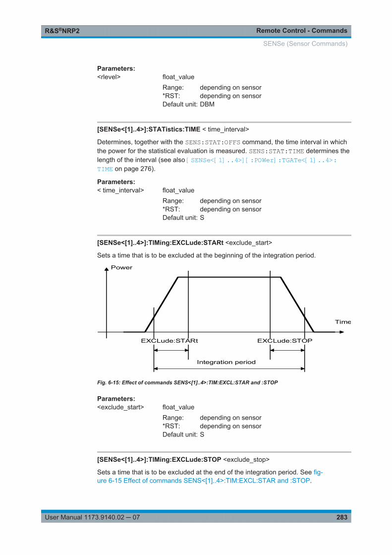
Remote Control - CommandsR&S®NRP2
283User Manual 1173.9140.02 ─ 07
Parameters:<rlevel> float_value
Range: depending on sensor*RST: depending on sensorDefault unit: DBM
[SENSe<[1]..4>]:STATistics:TIME < time_interval>
Determines, together with the SENS:STAT:OFFS command, the time interval in whichthe power for the statistical evaluation is measured. SENS:STAT:TIME determines thelength of the interval (see also [SENSe<[1]..4>][:POWer]:TGATe<[1]..4>:TIME on page 276).
Parameters:< time_interval> float_value
Range: depending on sensor*RST: depending on sensorDefault unit: S
[SENSe<[1]..4>]:TIMing:EXCLude:STARt <exclude_start>
Sets a time that is to be excluded at the beginning of the integration period.
Integration period
EXCLude:STARt EXCLude:STOP
Power
Time
Fig. 6-15: Effect of commands SENS<[1]..4>:TIM:EXCL:STAR and :STOP
Parameters:<exclude_start> float_value
Range: depending on sensor*RST: depending on sensorDefault unit: S
[SENSe<[1]..4>]:TIMing:EXCLude:STOP <exclude_stop>
Sets a time that is to be excluded at the end of the integration period. See fig-ure 6-15 Effect of commands SENS<[1]..4>:TIM:EXCL:STAR and :STOP.
SENSe (Sensor Commands)
Remote Control - CommandsR&S®NRP2
284User Manual 1173.9140.02 ─ 07
Parameters:<exclude_stop> float_value
Range: depending on sensor*RST: depending on sensor
[SENSe<[1]..4>]:TRACe:AVERage[:STATe] <state>
Switches the filter function of a sensor on or off for the Trace mode. When the filter isswitched on, the number of measured values set with[SENSe<[1]..4>]:AVERage:COUNt is averaged. This reduces the effect of noiseso that more reliable results are obtained.
Parameters:<state> ON | OFF
*RST: depending on sensor
[SENSe<[1]..4>]:TRACe:AVERage:COUNt <filter_length>
Sets the length of the filter for the Trace mode. The wider the filter, the lower the noiseand the longer it takes to obtain a measured value.
Note:
The SENS:TRAC:AVER:COUN command switches the automatic filter length switch-over off (SENS:TRAC:AVER:COUN:AUTO OFF).
Parameters:<filter_length> The filter length can only be 1, 2, 4, 8, 16,..., 2n. If the entered
filter length is not a power of two, the value is rounded to thenext 2n value without an error message.Range: depending on sensor*RST: depending on sensor
[SENSe<[1]..4>]:TRACe:AVERage:COUNt:AUTO <state>
Can be used to automatically determine a value for[SENSe<[1]..4>]:AVERage:COUNt for the trace mode.
SENSe (Sensor Commands)
Remote Control - CommandsR&S®NRP2
285User Manual 1173.9140.02 ─ 07
Parameters:<state> ON | OFF | ONCE
ONThe automatic switchover is activated, the sensor alwaysdefines a suitable filter length which can also be queried viaSENS<[1]..4>:AVER:COUN?OFFThe automatic switchover is deactivated.ONCEThe automatic switchover is deactivated and the suitable filterlength is then defined and set automatically. The setting canthen be queried via SENS<[1]..4>:AVER:COUN?*RST: depending on sensor
[SENSe<[1]..4>]:TRACe:AVERage:COUNt:AUTO:MTIMe <mtime>
If the R&S NRP2 has to determine the filter length automatically in the Trace mode, thefilter length can become large and thus also the time to fill the filter. An upper time limit(maximum time) can be set via SENS<[1]..4>:AVER:COUN:AUTO:MTIME. It shouldnever be exceeded. Undesired long measurement times can thus be prevented (in theSENS:AVER:COUN:AUTO:TYPE NSR mode) if the automatic filter length switchover ison.
Parameters:<mtime> float_value
Range: depending on sensor*RST: depending on sensorDefault unit: S
[SENSe<[1]..4>]:TRACe:AVERage:COUNt:AUTO:RESolution <resolution>
Defines the number of significant places for the Trace mode for linear units and thenumber of decimal places for logarithmic units which should be free of noise in themeasurement result. This setting is also performed by the command DISPlay[:WINDow]<[1]..4>:RESolution on page 245 which tries to set the sensorsinvolved in the measurement result accordingly. For further details, see chapter 4,"Instrument Functions", on page 61.
However, SENS<[1]..4>:AVER:COUN:AUTO:RES does not affect the DISPlaycommand. The parameters of the two commands are different but have the samemeaning.
SENS<[1]..4>:AVER:COUN:AUTO:RES 1 2 3 4
DISP<[1]..4>:RES 1 0.1 0.01 0.001
SENSe (Sensor Commands)
Remote Control - CommandsR&S®NRP2
286User Manual 1173.9140.02 ─ 07
Parameters:<resolution> 1 | 2 | 3 | 4
Range: depending on sensor*RST: depending on sensor
[SENSe<[1]..4>]:TRACe:AVERage:COUNt:AUTO:POINt <value>
Specifies the measured value in the Trace mode used for the automatic determinationof the filter length.
Parameters:<value> int_value
Range: depending on sensor*RST: depending on sensor
[SENSe<[1]..4>]:TRACe:AVERage:COUNt:AUTO:NSRatio <maximum_noise>
Indicates the maximum noise ratio in the measurement result for the Trace mode. Thesetting is taken into account only if SENS<[1]..4>]:TRAC:AVER:COUN:AUTO ONand SENS<[1]..4>]:TRAC:AVER:COUN:AUTO:TYPE NSR are set.
Unit: DB | PCT
Parameters:<maximum_noise> float_value
Range: depending on sensor*RST: depending on sensorDefault unit: DB
[SENSe<[1]..4>]:TRACe:AVERage:COUNt:AUTO:TYPE <trace_mode>
Selects the operating method for the automatic filter length in trace mode.
Parameters:<trace_mode> RESolution
Takes command SENS<[1]..4>:AVER:COUN:AUTO:RES intoaccount.NSRTakes command SENS<[1]..4>:AVER:COUN:AUTO:NSR intoaccount.SENS<[1]..4>:AVER:COUN:AUTO:MTIM*RST: depending on sensor
SENSe (Sensor Commands)
Remote Control - CommandsR&S®NRP2
287User Manual 1173.9140.02 ─ 07
[SENSe<[1]..4>]:TRACe:AVERage:TCONtrol <terminal_control>
As soon as a new single value is determined, the filter window is advanced by onevalue so that the new value is taken into account by the filter and the oldest value isforgotten. [SENSe<[1]..4>]:AVERage:TCONtrol (terminal control) then deter-mines in the Trace mode whether a new result will be calculated immediately after anew measured value is available (MOVing) or only after an entire range of new valuesis available for the filter (REPeat).
Parameters:<terminal_control> MOVing | REPeat
*RST: REP; (PRES) and SYST:PRES:MOV;
[SENSe<[1]..4>]:TRACe:MEASurement:ALGorithm <algorithm>
Selects the analysis algorithm for detecting the pulse top and the pulse base power ofa pulsed signal. These two power levels are fundamental for further signal analysis.
Parameters:<algorithm> HISTogram
Computes the pulse levels by analyzing the histogram of thetrace data. The pulse top level is taken on the mean value of allpoints representing the pulse top. Similarly the pulse base isdetermined from the points representing the pulse base.Note: This algorithm is recommended for analyzing most of thepulse signals.INTegrationComputes the pulse as a reference top power by fitting a rectan-gle pulse of same energy into the pulse signal.Note: Use this algorithm for pulse signals with modulation orwhen the pulse energy must be taken into account, e.g. whencomparing the measurement result with a dual thermal powersensor.PEAKAssigns the pulse peak power to the pulse top level.*RST: depending on the sensor
[SENSe<[1]..4>]:TRACe:MEASurement:AUTO[:STATe] <state>
Switches on/off automatic transfer of the measured pulse parameters after each trace.This enables a synchronous display of the trace and the pulse data during a continu-ous measurement with INIT:CONT ON.
For pulse measurements, this settings has to be switched ON. See alsoSENS:TRAC:MEAS:STAT.
Parameters:<state> ON | OFF
*RST: depending on the sensor
SENSe (Sensor Commands)
Remote Control - CommandsR&S®NRP2
288User Manual 1173.9140.02 ─ 07
[SENSe<[1]..4>]:TRACe:MEASurement:DEFine:DURation:REFerence <ref_level>
Sets the medial reference level in terms of percentage of the pulse power amplitude.This level is used to define the pulse width, pulse start time and pulse stop time.
Unit: PCT | O
Parameters:<ref_level> float_value
Range: depending on the sensor*RST: depending on the sensorDefault unit: PCT
[SENSe<[1]..4>]:TRACe:MEASurement:DEFine:TRANsition:HREFerence<href_level>
Sets the high reference level in terms of percentage of the pulse power amplitude. The"High Ref. Power" defines the end of the rising edge and the start of the falling edge ofthe pulse. These values are needed for measurement of the rise / fall time.
Unit: PCT | O
Parameters:<ref_level> float_value
Range: depending on the sensor*RST: depending on the sensorDefault unit: PCT
[SENSe<[1]..4>]:TRACe:MEASurement:DEFine:TRANsition:LREFerence<lref_level>
Sets the low reference level in terms of percentage of the pulse power amplitude. The"Low Ref. Power" defines the start of the rising edge and the end of the falling edge ofthe pulse. These values are needed for measurement of the rise / fall time.
Unit: PCT | O
Parameters:<ref_level> float_value
Range: depending on the sensor*RST: depending on the sensorDefault unit: PCT
[SENSe<[1]..4>]:TRACe:MEASurement:POWer:AVG?
Returns the measured average power in the current trace.
Unit: WATT
Usage: Query only
SENSe (Sensor Commands)
Remote Control - CommandsR&S®NRP2
289User Manual 1173.9140.02 ─ 07
[SENSe<[1]..4>]:TRACe:MEASurement:POWer:MAX?
Returns the measured maximum power in the current trace.
Unit: WATT
Usage: Query only
[SENSe<[1]..4>]:TRACe:MEASurement:POWer:MIN?
Returns the measured minimum power in the current trace.
Unit: WATT
Usage: Query only
[SENSe<[1]..4>]:TRACe:MEASurement:POWer:PULSe:BASE?
Returns the base power, computed in the pulse level analysis histogram of the currenttrace data.
Unit: WATT
Usage: Query only
[SENSe<[1]..4>]:TRACe:MEASurement:POWer:PULSe:TOP?
Returns the power of the first detected complete pulse of the current trace data, includ-ing rising and falling edges.
Unit: WATT
Usage: Query only
[SENSe<[1]..4>]:TRACe:MEASurement:PULSe:DCYCle?
Returns the duty cycle of the current trace data.
Unit: PCT
Usage: Query only
[SENSe<[1]..4>]:TRACe:MEASurement:PULSe:DURation?
Returns the pulse duration (pulse width) of the first detected pulse in the current trace.
Unit: S
Usage: Query only
[SENSe<[1]..4>]:TRACe:MEASurement:PULSe:PERiod?
Returns the time the pulse signal needs to complete one cycle.
SENSe (Sensor Commands)
Remote Control - CommandsR&S®NRP2
290User Manual 1173.9140.02 ─ 07
Unit: S
Usage: Query only
[SENSe<[1]..4>]:TRACe:MEASurement:PULSe:SEParation?
Returns the time from "Stop Time" to "Start Time" of the first detected pulse.
Unit: S
Usage: Query only
[SENSe<[1]..4>]:TRACe:MEASurement:TRANSition:ESAMpling:AUTO[:STATe]?
Activates ON or deactivates OFF the equivalent sampling mode, which allows for highresolution measurements.
Parameters:<state> ON | OFF
*RST: depending on the sensor
Usage: Query only
[SENSe<[1]..4>]:TRACe:MEASurement:TRANSition:NEGative:DURation?
Returns the fall time of the first detected pulse. The fall time is the time the signalrequires to change from high to low level. High and low levels can be adjusted usingthe commands SENS:TRAC:MEAS:DEF:TRAN:HREF andSENS:TRAC:MEAS:DEF:TRAN:LREF.
Unit: S
Usage: Query only
[SENSe<[1]..4>]:TRACe:MEASurement:TRANSition:NEGative:OCCurrence?
Returns the stop point of the current pulse, i.e. the time when the signal passesthrough the medial reference level with falling edge. The medial level can be adjustedusing the command SENS:TRAC:MEAS:DEF:DUR:REF.
Unit: S
Usage: Query only
[SENSe<[1]..4>]:TRACe:MEASurement:TRANSition:NEGative:OVERshoot?
Returns the amount of relative undershooting of the signal at the end of a pulse.
Unit: PCT
Usage: Query only
SENSe (Sensor Commands)
Remote Control - CommandsR&S®NRP2
291User Manual 1173.9140.02 ─ 07
[SENSe<[1]..4>]:TRACe:MEASurement:TRANSition:POSitive:DURation?
Returns the rise time of the first detected pulse. The rise time is the time the signalrequires to change from low to high level. High and low levels can be adjusted usingthe commands SENS:TRAC:MEAS:DEF:TRAN:HREF andSENS:TRAC:MEAS:DEF:TRAN:LREF.
Unit: S
Usage: Query only
[SENSe<[1]..4>]:TRACe:MEASurement:TRANSition:POSitive:OCCurrence?
Returns the start point of the current pulse, i.e. the time when the signal passesthrough the medial reference level with rising edge. The medial level can be adjustedusing the command SENS:TRAC:MEAS:DEF:DUR:REF.
Unit: S
Usage: Query only
[SENSe<[1]..4>]:TRACe:MEASurement:TRANSition:POSitive:OVERshoot?
Returns the amount of relative undershooting of the signal at the beginning of a pulse.
Unit: PCT
Usage: Query only
[SENSe<[1]..4>]:TRACe:MEASurement:TRANSition:SPERiod?
Returns the resolution of time-related pulse parameters in s. The respective valuedepends on the pulse measurement configuration and the measured signal.
Unit: O
Usage: Query only
[SENSe<[1]..4>]:TRACe:MEASurement[:STATe] <state>
Switches on/off automatic pulse measurements in the Trace mode. If pulse measure-ment is on, the sensor automatically determines the pulse parameters for the currentlymeasured trace. For pulse measurements, also set SENS:TRAC:MEAS:AUTO ON.
Parameters:<state> ON | OFF
*RST: depending on the sensor
SENSe (Sensor Commands)
Remote Control - CommandsR&S®NRP2
292User Manual 1173.9140.02 ─ 07
[SENSe<[1]..4>]:TRACe:MID:OFFSet:TIME
Defines an offset for pulse analysis on the time axis measured from the trigger event.In conjunction with SENS:TRAC:MEAS:TIME this command can be used to define agate on a trace measurement, in which the pulse analysis shall be performed. If thegate spans the same time interval as the trace measurement, the first detected pulsewill be analyzed. Using a gate, it is possible to investigate successive pulses.
Parameters:<time> float_value
Range: depending on the sensor*RST: depending on the sensorDefault unit: S
[SENSe<[1]..4>]:TRACe:MID:TIME
Defines the considered length for pulse analysis on the time axis. In conjunction withSENS:TRAC:MEAS:OFFS:TIME this command can be used to define a gate on a tracemeasurement, in which the pulse analysis shall be performed. If the gate spans thesame time interval as the trace measurement, the first detected pulse will be analyzed.Using a gate, it is possible to investigate successive pulses.
Parameters:<time> float_value
Range: depending on the sensor*RST: depending on the sensorDefault unit: S
[SENSe<[1]..4>]:TRACe:OFFSet:TIME <time>
Determines the relative position of the trigger event in relation to the beginning of theTrace measurement sequence.
Parameters:<time> float_value
Range: depending on sensor*RST: depending on sensorDefault unit: S
[SENSe<[1]..4>]:TRACe:POINts <points>
Sets the number of desired values per Trace sequence.
Error messages:
28 "Sensor not idle": The sensor is not in the IDLE state.
SENSe (Sensor Commands)
Remote Control - CommandsR&S®NRP2
293User Manual 1173.9140.02 ─ 07
Parameters:int_valueRange: depending on sensor*RST: depending on sensor
[SENSe<[1]..4>]:TRACe:REALtime <state>
In the default state (OFF), each measurement from the sensor is averaged. With[SENSe<[1]..4>]:TRACe::REALtime ON , this behaviour can be switched off,which may increase the measurement speed. With a higher measurement speed themeasured values of an individual measurement are immediately delivered.
Parameters:<state> ON | OFF
*RST: depending on sensor
[SENSe<[1]..4>]:TRACe:TIME <time>
Sets the time to be covered by the Trace sequence.
Parameters:<time> float_value
Range: depending on sensor*RST: depending on sensorDefault unit: S
6.12 SERVice
The commands of the SERVice system are used for maintenance or test purposes.They were implemented primarily to support device development. The numeric suffixrefers to the sensors.
Before commands of the SERVice system can be sent to a sensor, they must beenabled via the SERVice:UNLock 1234 command.
SERVice<[1]..4>:CALibration:TEST?............................................................................... 294SERVice<[1]..4>:CALibration:TEMP.................................................................................294SERVice<[1]..4>:CALibration:TEMP:DATA?..................................................................... 294SERVice:DISPlay:OVERload.......................................................................................... 294SERVice<[1]..4>:RCOunt................................................................................................295SERVice<[1]..4>:RESult................................................................................................. 295SERVice<[1]..4>:SERRors..............................................................................................295SERVice<[1]..4>:UNLock................................................................................................295
SERVice
Remote Control - CommandsR&S®NRP2
294User Manual 1173.9140.02 ─ 07
SERVice<[1]..4>:CALibration:TEST? <NR1>
Tests the consistency of the calibration data set according to three criteria:
If the following bit is set in<nr1>,
the following action is executed.
0 The serial number of the calibration data set is tested.
1 The checksum of the calibration data set is tested.
2 The header of the calibration data set is tested.
If an inconsistency of the data set is detected, the query returns a 1, otherwise a 0.
Parameters:<NR1> int_value
Range: 0 to 255
Usage: Query only
SERVice<[1]..4>:CALibration:TEMP <state>
Initiates a temperature measurement of the sensor in question. The temperature canbe queried with SERV:CAL:TEMP:DATA?.
Parameters:<state> ONCE
Usage: Event
SERVice<[1]..4>:CALibration:TEMP:DATA?
Returns the temperature of the sensor in Kelvin if a temperature measurement waspreviously initiated by means of SERV:CAL:TEMP ONCE.
Usage: Query only
SERVice:DISPlay:OVERload <state>
Switches the sensor overload warning on/off.
Attention:
If the sensor is overloaded, it could be damaged! The warning should not be sup-pressed if you are not certain that the sensor is out of danger.
Parameters:<state> ON | OFF
*RST: ON
SERVice
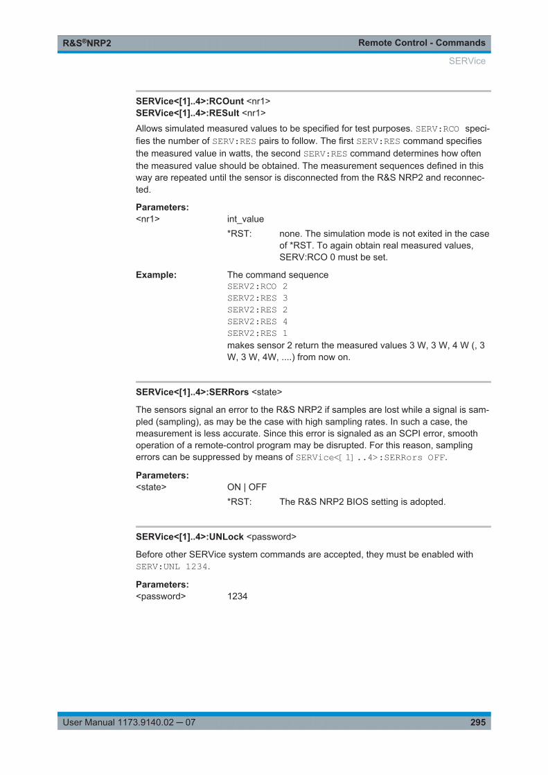
Remote Control - CommandsR&S®NRP2
295User Manual 1173.9140.02 ─ 07
SERVice<[1]..4>:RCOunt <nr1>SERVice<[1]..4>:RESult <nr1>
Allows simulated measured values to be specified for test purposes. SERV:RCO speci-fies the number of SERV:RES pairs to follow. The first SERV:RES command specifiesthe measured value in watts, the second SERV:RES command determines how oftenthe measured value should be obtained. The measurement sequences defined in thisway are repeated until the sensor is disconnected from the R&S NRP2 and reconnec-ted.
Parameters:<nr1> int_value
*RST: none. The simulation mode is not exited in the caseof *RST. To again obtain real measured values,SERV:RCO 0 must be set.
Example: The command sequenceSERV2:RCO 2SERV2:RES 3SERV2:RES 2SERV2:RES 4SERV2:RES 1makes sensor 2 return the measured values 3 W, 3 W, 4 W (, 3W, 3 W, 4W, ....) from now on.
SERVice<[1]..4>:SERRors <state>
The sensors signal an error to the R&S NRP2 if samples are lost while a signal is sam-pled (sampling), as may be the case with high sampling rates. In such a case, themeasurement is less accurate. Since this error is signaled as an SCPI error, smoothoperation of a remote-control program may be disrupted. For this reason, samplingerrors can be suppressed by means of SERVice<[1]..4>:SERRors OFF.
Parameters:<state> ON | OFF
*RST: The R&S NRP2 BIOS setting is adopted.
SERVice<[1]..4>:UNLock <password>
Before other SERVice system commands are accepted, they must be enabled withSERV:UNL 1234.
Parameters:<password> 1234
SERVice
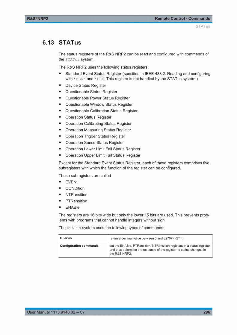
Remote Control - CommandsR&S®NRP2
296User Manual 1173.9140.02 ─ 07
6.13 STATus
The status registers of the R&S NRP2 can be read and configured with commands ofthe STATus system.
The R&S NRP2 uses the following status registers:● Standard Event Status Register (specified in IEEE 488.2. Reading and configuring
with *ESR? and *ESE. This register is not handled by the STATus system.)● Device Status Register● Questionable Status Register● Questionable Power Status Register● Questionable Window Status Register● Questionable Calibration Status Register● Operation Status Register● Operation Calibrating Status Register● Operation Measuring Status Register● Operation Trigger Status Register● Operation Sense Status Register● Operation Lower Limit Fail Status Register● Operation Upper Limit Fail Status Register
Except for the Standard Event Status Register, each of these registers comprises fivesubregisters with which the function of the register can be configured.
These subregisters are called● EVENt● CONDition● NTRansition● PTRansition● ENABle
The registers are 16 bits wide but only the lower 15 bits are used. This prevents prob-lems with programs that cannot handle integers without sign.
The STATus system uses the following types of commands:
Queries return a decimal value between 0 and 32767 (=215-1).
Configuration commands set the ENABle, PTRansition, NTRansition registers of a status registerand thus determine the response of the register to status changes inthe R&S NRP2.
STATus
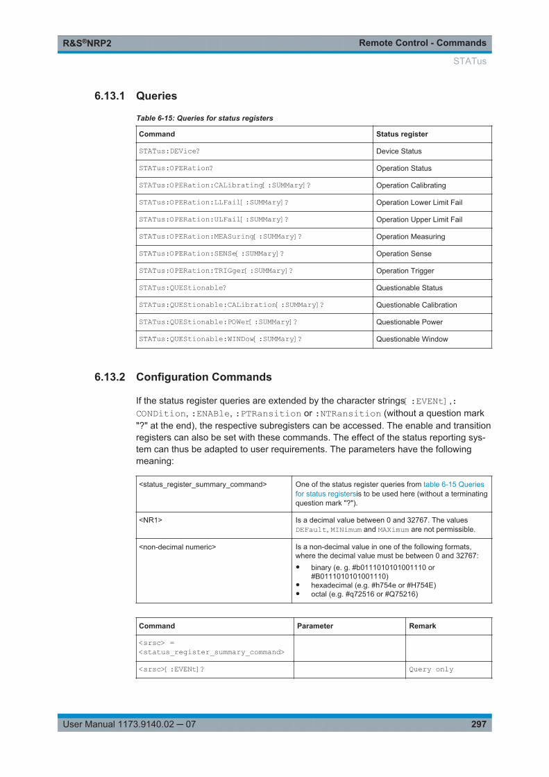
Remote Control - CommandsR&S®NRP2
297User Manual 1173.9140.02 ─ 07
6.13.1 Queries
Table 6-15: Queries for status registers
Command Status register
STATus:DEVice? Device Status
STATus:OPERation? Operation Status
STATus:OPERation:CALibrating[:SUMMary]? Operation Calibrating
STATus:OPERation:LLFail[:SUMMary]? Operation Lower Limit Fail
STATus:OPERation:ULFail[:SUMMary]? Operation Upper Limit Fail
STATus:OPERation:MEASuring[:SUMMary]? Operation Measuring
STATus:OPERation:SENSe[:SUMMary]? Operation Sense
STATus:OPERation:TRIGger[:SUMMary]? Operation Trigger
STATus:QUEStionable? Questionable Status
STATus:QUEStionable:CALibration[:SUMMary]? Questionable Calibration
STATus:QUEStionable:POWer[:SUMMary]? Questionable Power
STATus:QUEStionable:WINDow[:SUMMary]? Questionable Window
6.13.2 Configuration Commands
If the status register queries are extended by the character strings[:EVENt],:CONDition, :ENABle, :PTRansition or :NTRansition (without a question mark"?" at the end), the respective subregisters can be accessed. The enable and transitionregisters can also be set with these commands. The effect of the status reporting sys-tem can thus be adapted to user requirements. The parameters have the followingmeaning:
<status_register_summary_command> One of the status register queries from table 6-15 Queriesfor status registersis to be used here (without a terminatingquestion mark "?").
<NR1> Is a decimal value between 0 and 32767. The valuesDEFault, MINimum and MAXimum are not permissible.
<non-decimal numeric> Is a non-decimal value in one of the following formats,where the decimal value must be between 0 and 32767:● binary (e. g. #b0111010101001110 or
#B0111010101001110)● hexadecimal (e.g. #h754e or #H754E)● octal (e.g. #q72516 or #Q75216)
Command Parameter Remark
<srsc> =<status_register_summary_command>
<srsc>[:EVENt]? Query only
STATus
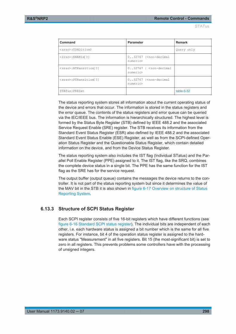
Remote Control - CommandsR&S®NRP2
298User Manual 1173.9140.02 ─ 07
Command Parameter Remark
<srsc>:CONDition? Query only
<srsc>:ENABle[?] 0..32767 |<non-decimalnumeric>
<srsc>:NTRansition[?] 0..32767 | <non-decimalnumeric>
<srsc>:PTRansition[?] 0..32767 |<non-decimalnumeric>
STATus:PRESet table 6-32
The status reporting system stores all information about the current operating status ofthe device and errors that occur. The information is stored in the status registers andthe error queue. The contents of the status registers and error queue can be queriedvia the IEC/IEEE bus. The information is hierarchically structured. The highest level isformed by the Status Byte Register (STB) defined by IEEE 488.2 and the associatedService Request Enable (SRE) register. The STB receives its information from theStandard Event Status Register (ESR) also defined by IEEE 488.2 and the associatedStandard Event Status Enable (ESE) Register, as well as from the SCPI-defined Oper-ation Status Register and the Questionable Status Register, which contain detailedinformation on the device, and from the Device Status Register.
The status reporting system also includes the IST flag (Individual STatus) and the Par-allel Poll Enable Register (PPE) assigned to it. The IST flag, like the SRQ, combinesthe complete device status in a single bit. The PPE has the same function for the ISTflag as the SRE has for the service request.
The output buffer (output queue) contains the messages the device returns to the con-troller. It is not part of the status reporting system but since it determines the value ofthe MAV bit in the STB it is also shown in figure 6-17 Overview on structure of StatusReporting System.
6.13.3 Structure of SCPI Status Register
Each SCPI register consists of five 16-bit registers which have different functions (seefigure 6-16 Standard SCPI status register). The individual bits are independent of eachother, i.e. each hardware status is assigned a bit number which is the same for all fiveregisters. For instance, bit 4 of the operation status register is assigned to the hard-ware status "Measurement" in all five registers. Bit 15 (the most-significant bit) is set tozero in all registers. This prevents problems some controllers have with the processingof unsigned integers.
STATus
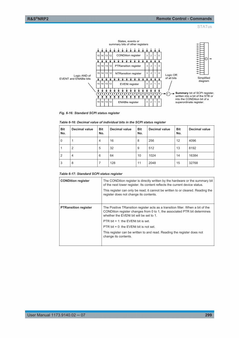
Remote Control - CommandsR&S®NRP2
299User Manual 1173.9140.02 ─ 07
123 0131415 12 PTRansition register
&&&& + Summary bit of SCPI register,written into a bit of the STB orinto the CONDition bit of asuperordinate register.
Logic ORof all bits
Logic AND ofEVENT and ENABle bits
&&&&&&&&&&&&
CONDition register 123 0131415 12
NTRansition register 123 0131415 12
EVENt register 123 0131415 12
ENABle register 123 0131415 12
States, events orsummary bits of other registers
+
Simplifieddiagram
Fig. 6-16: Standard SCPI status register
Table 6-16: Decimal value of individual bits in the SCPI status register
BitNo.
Decimal value BitNo.
Decimal value BitNo.
Decimal value BitNo.
Decimal value
0 1 4 16 8 256 12 4096
1 2 5 32 9 512 13 8192
2 4 6 64 10 1024 14 16384
3 8 7 128 11 2048 15 32768
Table 6-17: Standard SCPI status register
CONDition register The CONDition register is directly written by the hardware or the summary bitof the next lower register. Its content reflects the current device status.
This register can only be read; it cannot be written to or cleared. Reading theregister does not change its contents.
PTRansition register The Positive TRansition register acts as a transition filter. When a bit of theCONDition register changes from 0 to 1, the associated PTR bit determineswhether the EVENt bit will be set to 1.
PTR bit = 1: the EVENt bit is set.
PTR bit = 0: the EVENt bit is not set.
This register can be written to and read. Reading the register does notchange its contents.
STATus
Remote Control - CommandsR&S®NRP2
300User Manual 1173.9140.02 ─ 07
NTRansition register The Negative TRansition register also acts as a transition filter. Upon transi-tion of a bit of the CONDition register from 1 to 0, the associated NTR bitdetermines whether the EVENt bit is set to 1.
NTR bit = 1: the EVENt bit is set.
NTR bit = 0: the EVENt bit is not set.
This register can be written to and read. Reading the register does notchange its contents.
With the aid of these two transition filter registers the user can define the sta-tus change of the CONDition register (none, 0 to 1, 1 to 0 or both) that is tobe recorded in the EVENt register.
EVENt register The EVENt register reports whether an event has occurred since its lastreading; it is the "memory" of the CONDition register. It only registers eventsthat have been reported by the transition filters. The EVENt register is contin-uously updated by the device.
It can only be read by the user. Reading this register clears its contents.
This register is frequently referred to as the overall register.
ENABle register The ENABle register determines whether the associated EVENt bit influen-ces the summary bit (see below). Each bit of the EVENt register is ANDed(symbol '&') with the associated ENABle bit. The events of all logical opera-tions of this register are ORed (symbol '+') and passed on to the summarybit.
ENABle bit = 0: the associated EVENt bit does not affect the summary bit. bit= 1: if the associated EVENT bit is "1", the summary bit is also set to "1".
This register can be written to and read as required. Reading the registerdoes not change its contents.
Summary bit As stated above, the summary bit for each register is derived from theEVENt and ENABle registers. The result is entered into a bit of the CONDi-tion register of the next higher register. The device automatically generatesthe summary bit for each register. An event may thus cause a servicerequest through all hierarchical levels.
The Service Request Enable register (SRE) defined by IEEE488.2 can be viewed asthe ENABle register of the STB. Accordingly, the ESE can be viewed as the ENABleregister of the ESR.
STATus

Remote Control - CommandsR&S®NRP2
301User Manual 1173.9140.02 ─ 07
&
&
&
&
&
&
&
10
2
MAV3
ESBRQS/MSS
7
+
10
2
43
5X7
0
0
00
0
0Uper Limit Fail
Lower Limit FailOperation SENSe Summary
0
Operation TRIG SummaryOperation MEAS Summary
00
Operation CAL Summary
+
0123456789
101112131415
0
Device StatusRegister
Questionable StatusRegister
Standard Event StatusRegister
Operation StatusRegister
Device dependent Error
Power OnUser Request
Command ErrorExecution Error
Query Error0
Operation Complete 01234567
+
Questionable Power Summary
Warning
Questionable Calibration SummaryPOST Failure
0123456789
1011121314150
0000
000
Questionable Window Summary
000
+
0123456789101112131415
Sensor A connected
Sensor A error
Sensor A Front/Rear
Key pressed
Sensor B connected
Sensor C connectedSensor D connected
Sensor B Front/Rear
Sensor C Front/RearSensor D Front/Rear
Sensor B error
Sensor C errorSensor D error
0
0
0
+
Status Byte*STB
Output Queue (output buffer)
Error-/Event Queue
Service Request Enable*SRE
Service Requestto controller
at transition from 0 to 1
STAT:DEV
STAT:QUES
*ESE
STAT:OPER
Fig. 6-17: Overview on structure of Status Reporting System
STATus
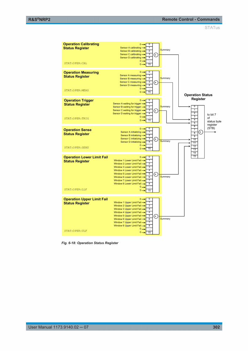
Remote Control - CommandsR&S®NRP2
302User Manual 1173.9140.02 ─ 07
Window 3 Upper Limit Fail
00
Window 4 Upper Limit Fail
Window 2 Upper Limit FailWindow 1 Upper Limit Fail
0
+
01234
Operation Upper Limit FailStatus Register
...15
5678
Window 7 Upper Limit FailWindow 8 Upper Limit Fail
Window 6 Upper Limit FailWindow 5 Upper Limit Fail
+
0123456789
101112131415
Sensor C calibrating
00
Sensor D calibrating
Sensor B calibratingSensor A calibrating
0
+
01234...
15
Sensor C measuring
00
Sensor D measuring
Sensor B measuringSensor A measuring
0
+
01234...
15
Sensor C waiting for trigger
00
Sensor D waiting for trigger
Sensor B waiting for triggerSensor A waiting for trigger
0
+
01234...
15
Sensor C initializing
00
Sensor D initializing
Sensor B initializingSensor A initializing
0
+
01234...
15
Window 3 Lower Limit Fail
00
Window 4 Lower Limit Fail
Window 2 Lower Limit FailWindow 1 Lower Limit Fail
0+
01234
Operation CalibratingStatus Register
Operation MeasuringStatus Register
Operation TriggerStatus Register
Operation SenseStatus Register
Operation Lower Limit FailStatus Register
Summary
Summary
Summary
Summary
Summary
Summary
to bit 7ofstatus byteregister(STB)
Operation StatusRegister
...15
5678
Window 7 Lower Limit FailWindow 8 Lower Limit Fail
Window 6 Lower Limit FailWindow 5 Lower Limit Fail
STAT:OPER:CAL
STAT:OPER:MEAS
STAT:OPER:TRIG
STAT:OPER:SENS
STAT:OPER:LLF
STAT:OPER:ULF
Fig. 6-18: Operation Status Register
STATus
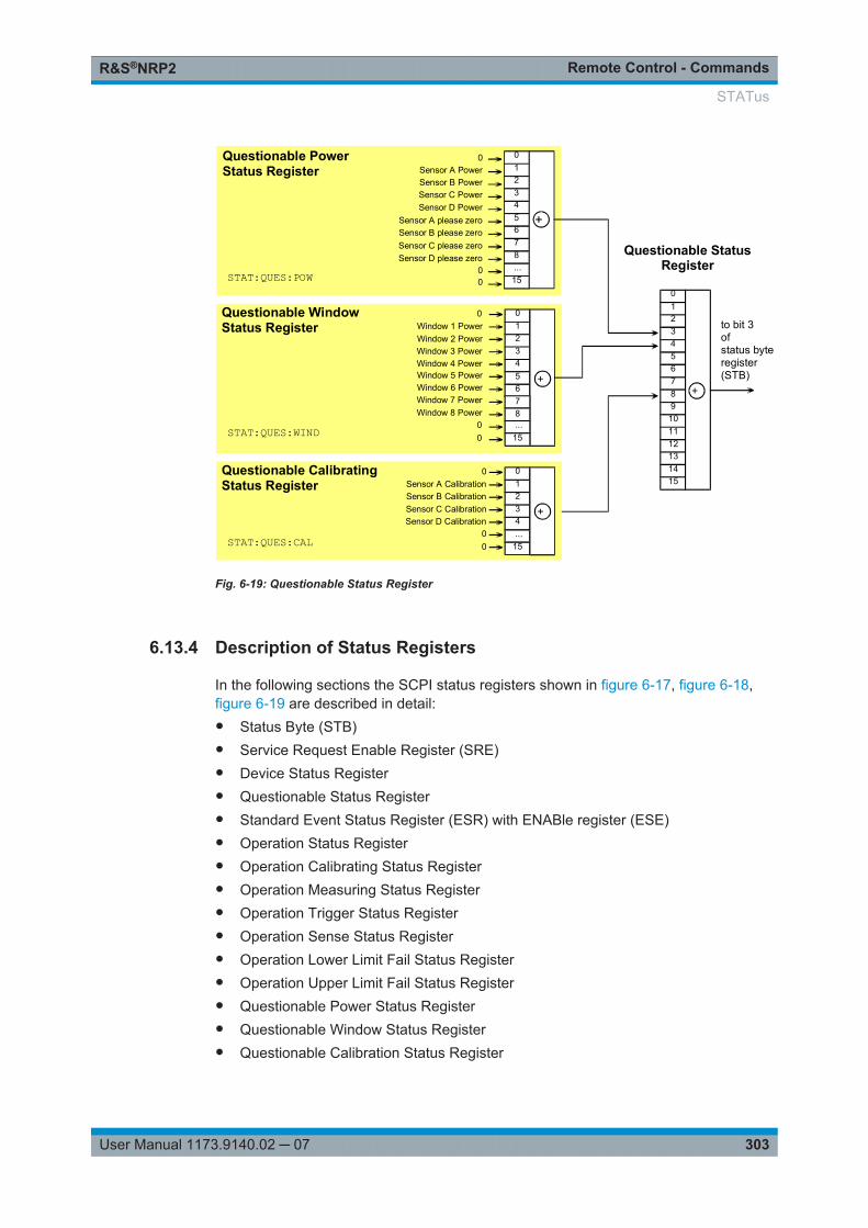
Remote Control - CommandsR&S®NRP2
303User Manual 1173.9140.02 ─ 07
+
0123456789101112131415
to bit 3ofstatus byteregister(STB)
Questionable StatusRegister
Questionable PowerStatus Register
012345678...15
Sensor A Power
Sensor A please zero
Sensor B PowerSensor C PowerSensor D Power
Sensor B please zeroSensor C please zeroSensor D please zero
0
+
00
0 01234
Questionable WindowStatus Register
Sensor C Calibration
00
Sensor D Calibration
Sensor B CalibrationSensor A Calibration
0
+
01234...
15
Questionable CalibratingStatus Register
Window 1 PowerWindow 2 PowerWindow 3 PowerWindow 4 Power
...15
5678
Window 5 PowerWindow 6 PowerWindow 7 PowerWindow 8 Power
00
+
STAT:QUES:POW
STAT:QUES:WIND
STAT:QUES:CAL
Fig. 6-19: Questionable Status Register
6.13.4 Description of Status Registers
In the following sections the SCPI status registers shown in figure 6-17, figure 6-18,figure 6-19 are described in detail:● Status Byte (STB)● Service Request Enable Register (SRE)● Device Status Register● Questionable Status Register● Standard Event Status Register (ESR) with ENABle register (ESE)● Operation Status Register● Operation Calibrating Status Register● Operation Measuring Status Register● Operation Trigger Status Register● Operation Sense Status Register● Operation Lower Limit Fail Status Register● Operation Upper Limit Fail Status Register● Questionable Power Status Register● Questionable Window Status Register● Questionable Calibration Status Register
STATus
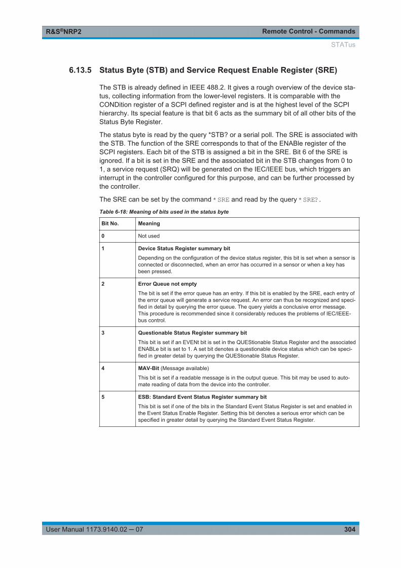
Remote Control - CommandsR&S®NRP2
304User Manual 1173.9140.02 ─ 07
6.13.5 Status Byte (STB) and Service Request Enable Register (SRE)
The STB is already defined in IEEE 488.2. It gives a rough overview of the device sta-tus, collecting information from the lower-level registers. It is comparable with theCONDition register of a SCPI defined register and is at the highest level of the SCPIhierarchy. Its special feature is that bit 6 acts as the summary bit of all other bits of theStatus Byte Register.
The status byte is read by the query *STB? or a serial poll. The SRE is associated withthe STB. The function of the SRE corresponds to that of the ENABle register of theSCPI registers. Each bit of the STB is assigned a bit in the SRE. Bit 6 of the SRE isignored. If a bit is set in the SRE and the associated bit in the STB changes from 0 to1, a service request (SRQ) will be generated on the IEC/IEEE bus, which triggers aninterrupt in the controller configured for this purpose, and can be further processed bythe controller.
The SRE can be set by the command *SRE and read by the query *SRE?.
Table 6-18: Meaning of bits used in the status byte
Bit No. Meaning
0 Not used
1 Device Status Register summary bit
Depending on the configuration of the device status register, this bit is set when a sensor isconnected or disconnected, when an error has occurred in a sensor or when a key hasbeen pressed.
2 Error Queue not empty
The bit is set if the error queue has an entry. If this bit is enabled by the SRE, each entry ofthe error queue will generate a service request. An error can thus be recognized and speci-fied in detail by querying the error queue. The query yields a conclusive error message.This procedure is recommended since it considerably reduces the problems of IEC/IEEE-bus control.
3 Questionable Status Register summary bit
This bit is set if an EVENt bit is set in the QUEStionable Status Register and the associatedENABLe bit is set to 1. A set bit denotes a questionable device status which can be speci-fied in greater detail by querying the QUEStionable Status Register.
4 MAV-Bit (Message available)
This bit is set if a readable message is in the output queue. This bit may be used to auto-mate reading of data from the device into the controller.
5 ESB: Standard Event Status Register summary bit
This bit is set if one of the bits in the Standard Event Status Register is set and enabled inthe Event Status Enable Register. Setting this bit denotes a serious error which can bespecified in greater detail by querying the Standard Event Status Register.
STATus
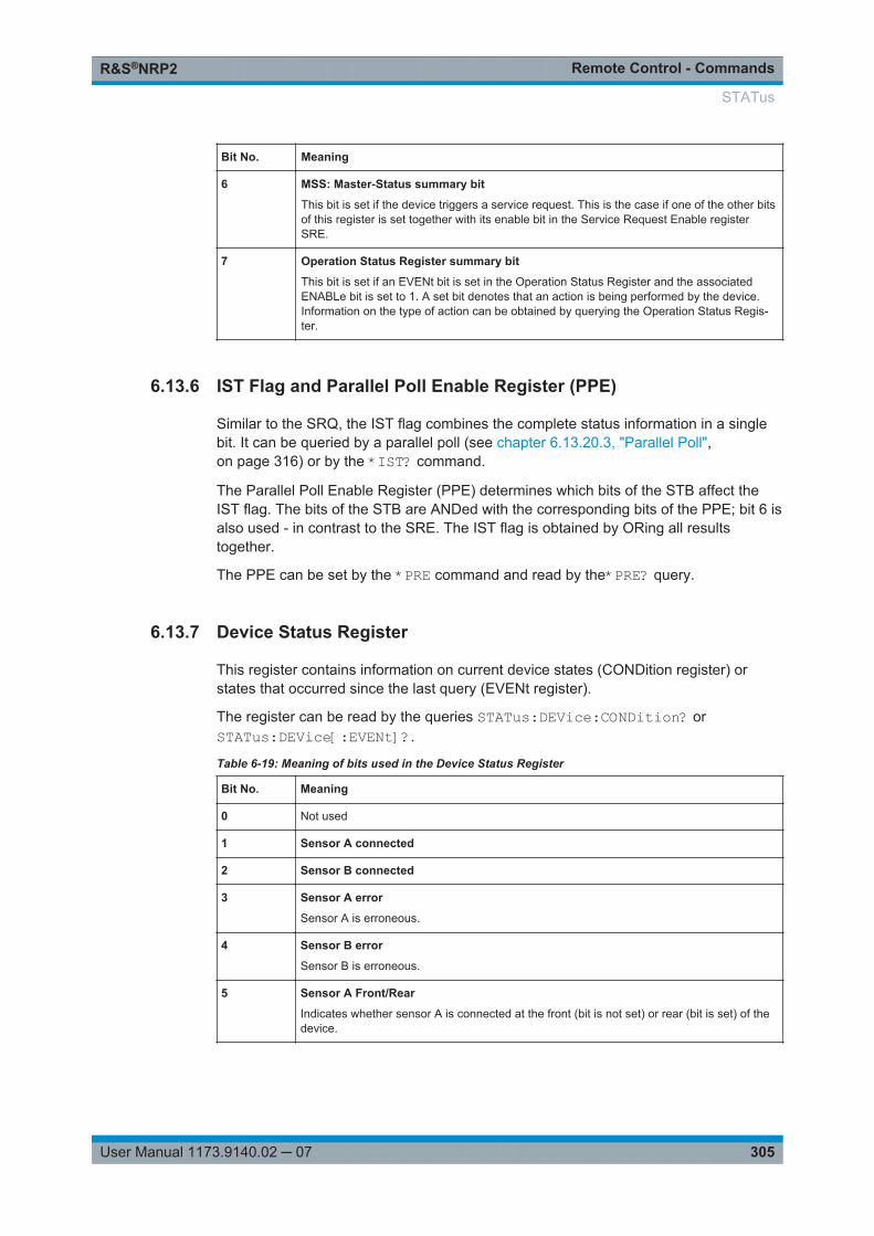
Remote Control - CommandsR&S®NRP2
305User Manual 1173.9140.02 ─ 07
Bit No. Meaning
6 MSS: Master-Status summary bit
This bit is set if the device triggers a service request. This is the case if one of the other bitsof this register is set together with its enable bit in the Service Request Enable registerSRE.
7 Operation Status Register summary bit
This bit is set if an EVENt bit is set in the Operation Status Register and the associatedENABLe bit is set to 1. A set bit denotes that an action is being performed by the device.Information on the type of action can be obtained by querying the Operation Status Regis-ter.
6.13.6 IST Flag and Parallel Poll Enable Register (PPE)
Similar to the SRQ, the IST flag combines the complete status information in a singlebit. It can be queried by a parallel poll (see chapter 6.13.20.3, "Parallel Poll",on page 316) or by the *IST? command.
The Parallel Poll Enable Register (PPE) determines which bits of the STB affect theIST flag. The bits of the STB are ANDed with the corresponding bits of the PPE; bit 6 isalso used - in contrast to the SRE. The IST flag is obtained by ORing all resultstogether.
The PPE can be set by the *PRE command and read by the*PRE? query.
6.13.7 Device Status Register
This register contains information on current device states (CONDition register) orstates that occurred since the last query (EVENt register).
The register can be read by the queries STATus:DEVice:CONDition? orSTATus:DEVice[:EVENt]?.
Table 6-19: Meaning of bits used in the Device Status Register
Bit No. Meaning
0 Not used
1 Sensor A connected
2 Sensor B connected
3 Sensor A error
Sensor A is erroneous.
4 Sensor B error
Sensor B is erroneous.
5 Sensor A Front/Rear
Indicates whether sensor A is connected at the front (bit is not set) or rear (bit is set) of thedevice.
STATus
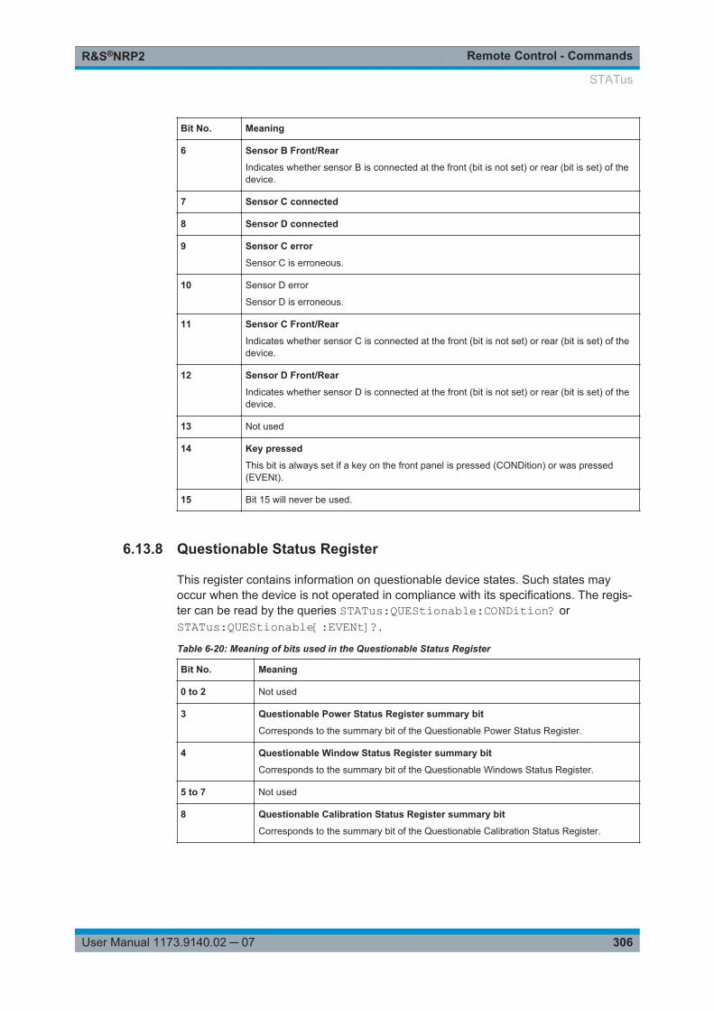
Remote Control - CommandsR&S®NRP2
306User Manual 1173.9140.02 ─ 07
Bit No. Meaning
6 Sensor B Front/Rear
Indicates whether sensor B is connected at the front (bit is not set) or rear (bit is set) of thedevice.
7 Sensor C connected
8 Sensor D connected
9 Sensor C error
Sensor C is erroneous.
10 Sensor D error
Sensor D is erroneous.
11 Sensor C Front/Rear
Indicates whether sensor C is connected at the front (bit is not set) or rear (bit is set) of thedevice.
12 Sensor D Front/Rear
Indicates whether sensor D is connected at the front (bit is not set) or rear (bit is set) of thedevice.
13 Not used
14 Key pressed
This bit is always set if a key on the front panel is pressed (CONDition) or was pressed(EVENt).
15 Bit 15 will never be used.
6.13.8 Questionable Status Register
This register contains information on questionable device states. Such states mayoccur when the device is not operated in compliance with its specifications. The regis-ter can be read by the queries STATus:QUEStionable:CONDition? orSTATus:QUEStionable[:EVENt]?.
Table 6-20: Meaning of bits used in the Questionable Status Register
Bit No. Meaning
0 to 2 Not used
3 Questionable Power Status Register summary bit
Corresponds to the summary bit of the Questionable Power Status Register.
4 Questionable Window Status Register summary bit
Corresponds to the summary bit of the Questionable Windows Status Register.
5 to 7 Not used
8 Questionable Calibration Status Register summary bit
Corresponds to the summary bit of the Questionable Calibration Status Register.
STATus
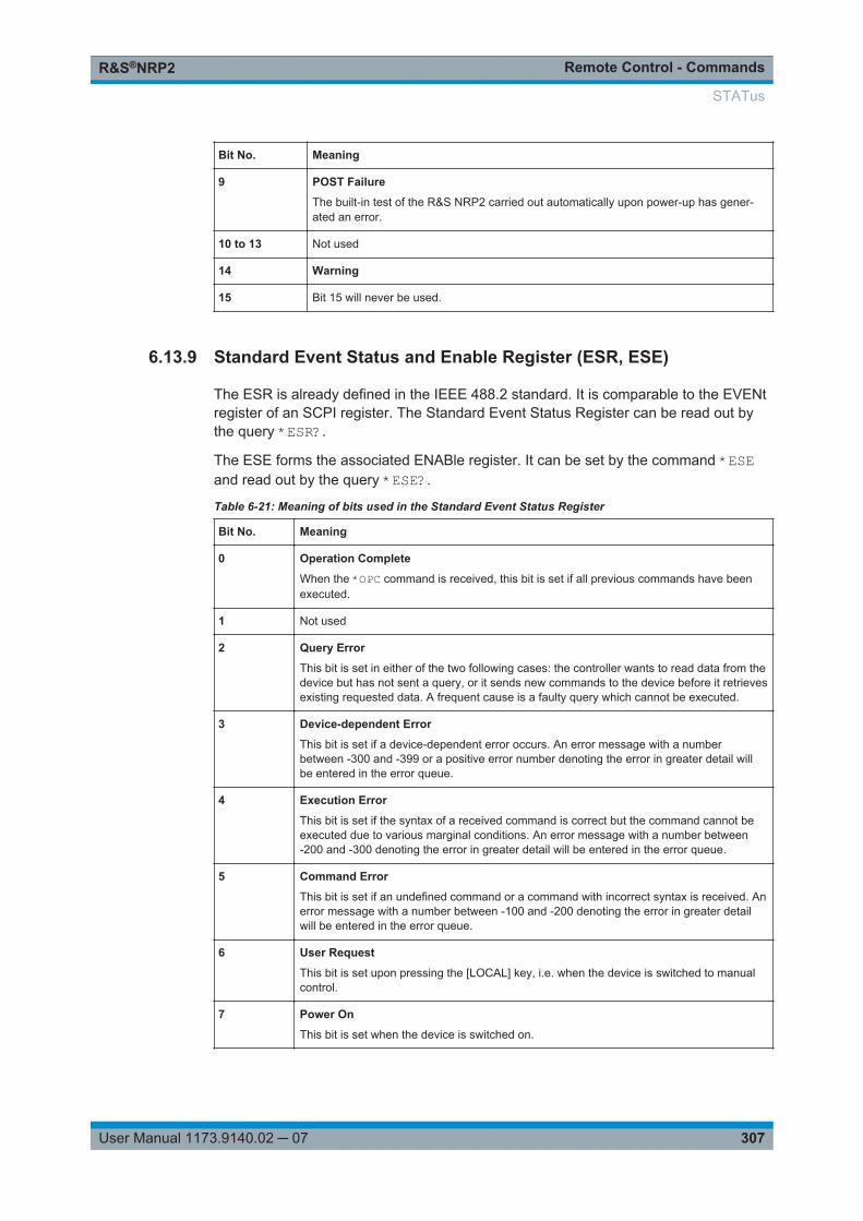
Remote Control - CommandsR&S®NRP2
307User Manual 1173.9140.02 ─ 07
Bit No. Meaning
9 POST Failure
The built-in test of the R&S NRP2 carried out automatically upon power-up has gener-ated an error.
10 to 13 Not used
14 Warning
15 Bit 15 will never be used.
6.13.9 Standard Event Status and Enable Register (ESR, ESE)
The ESR is already defined in the IEEE 488.2 standard. It is comparable to the EVENtregister of an SCPI register. The Standard Event Status Register can be read out bythe query *ESR?.
The ESE forms the associated ENABle register. It can be set by the command *ESEand read out by the query *ESE?.
Table 6-21: Meaning of bits used in the Standard Event Status Register
Bit No. Meaning
0 Operation Complete
When the *OPC command is received, this bit is set if all previous commands have beenexecuted.
1 Not used
2 Query Error
This bit is set in either of the two following cases: the controller wants to read data from thedevice but has not sent a query, or it sends new commands to the device before it retrievesexisting requested data. A frequent cause is a faulty query which cannot be executed.
3 Device-dependent Error
This bit is set if a device-dependent error occurs. An error message with a numberbetween -300 and -399 or a positive error number denoting the error in greater detail willbe entered in the error queue.
4 Execution Error
This bit is set if the syntax of a received command is correct but the command cannot beexecuted due to various marginal conditions. An error message with a number between-200 and -300 denoting the error in greater detail will be entered in the error queue.
5 Command Error
This bit is set if an undefined command or a command with incorrect syntax is received. Anerror message with a number between -100 and -200 denoting the error in greater detailwill be entered in the error queue.
6 User Request
This bit is set upon pressing the [LOCAL] key, i.e. when the device is switched to manualcontrol.
7 Power On
This bit is set when the device is switched on.
STATus

Remote Control - CommandsR&S®NRP2
308User Manual 1173.9140.02 ─ 07
6.13.10 Operation Status Register
The CONDition register contains information on the operations currently being per-formed by the device, while the EVENt register contains information on the operationsperformed by the device since the last readout of the register.
These two registers can be read by the queries STATus:OPERation:CONDition? orSTATus:OPERation[:EVENt]?.
Table 6-22: Meaning of bits used in the Operation Status Register
Bit No. Meaning
0 Operation Calibrating Status Register summary bit
This bit is set if one of the sensors is being calibrated.
1 to 3 Not used
4 Operation Measuring Status Register summary bit
This bit is set if one of the sensors is performing a measurement.
5 Operation Trigger Status Register summary bit
This bit is set if a sensor is in the WAIT_FOR_TRG state, i.e. waiting for a trigger event.
6 Not used
7 to 9 Not used
10 Operation Sense Status Register summary bit
This bit is set if a sensor is initialized.
11 Operation Lower Limit Fail Status Register
This bit is set if a displayed value has dropped below a lower limit value.
12 Operation Upper Limit Fail Status Register
This bit is set if a displayed value has exceeded an upper limit value.
13 to 14 Not used
15 Bit 15 will never be used.
6.13.11 Operation Calibrating Status Register
The CONDition register contains information as to whether a sensor is currently beingcalibrated and, depending on the configuration of the transition register, the EVENtregister indicates whether a calibration was started or completed since the last readoutof this register. The Operation Calibration Status Register can be read by the followingcommands:
STATus:OPERation:CALibrating[:SUMMary]:CONDition?STATus:OPERation:CALibrating[:SUMMary][:EVENt]? .
STATus
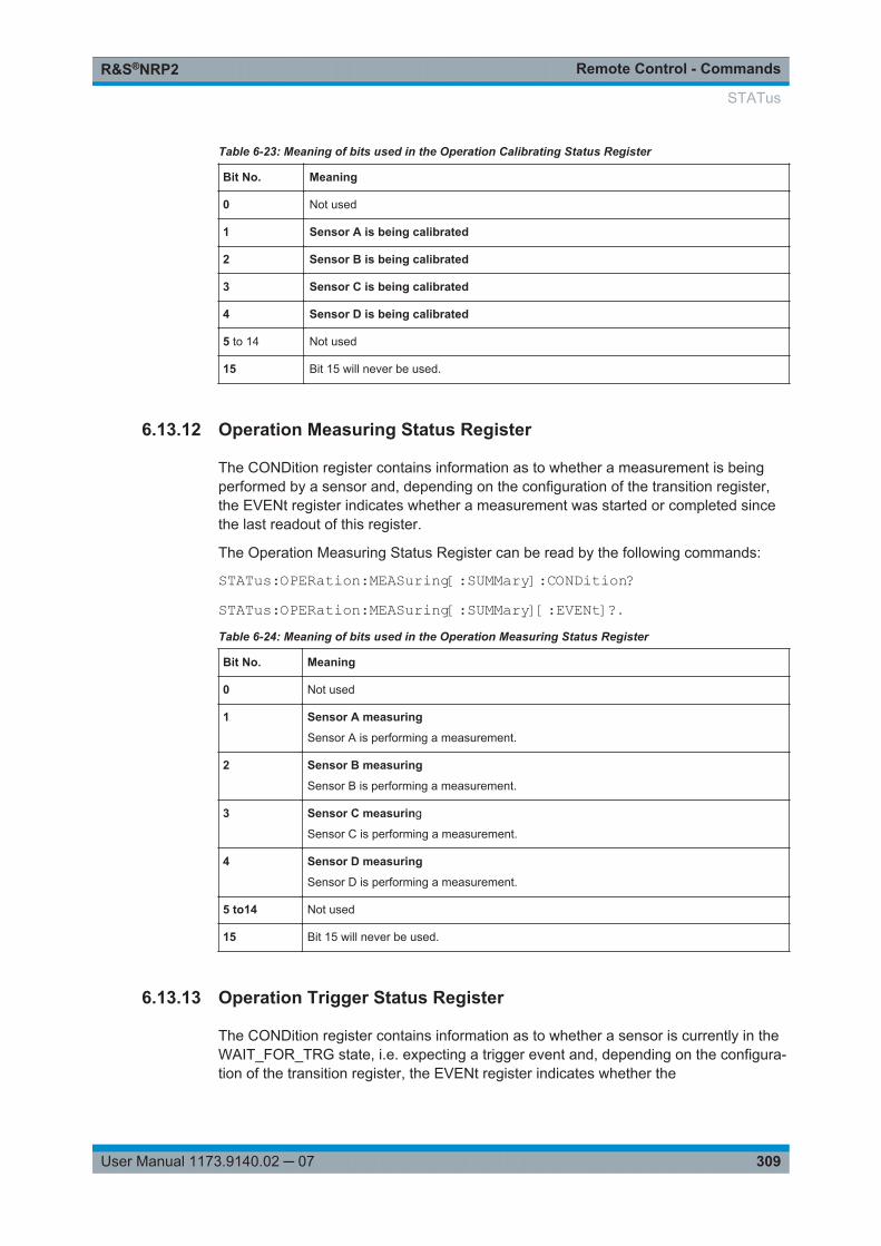
Remote Control - CommandsR&S®NRP2
309User Manual 1173.9140.02 ─ 07
Table 6-23: Meaning of bits used in the Operation Calibrating Status Register
Bit No. Meaning
0 Not used
1 Sensor A is being calibrated
2 Sensor B is being calibrated
3 Sensor C is being calibrated
4 Sensor D is being calibrated
5 to 14 Not used
15 Bit 15 will never be used.
6.13.12 Operation Measuring Status Register
The CONDition register contains information as to whether a measurement is beingperformed by a sensor and, depending on the configuration of the transition register,the EVENt register indicates whether a measurement was started or completed sincethe last readout of this register.
The Operation Measuring Status Register can be read by the following commands:
STATus:OPERation:MEASuring[:SUMMary]:CONDition?STATus:OPERation:MEASuring[:SUMMary][:EVENt]?.
Table 6-24: Meaning of bits used in the Operation Measuring Status Register
Bit No. Meaning
0 Not used
1 Sensor A measuring
Sensor A is performing a measurement.
2 Sensor B measuring
Sensor B is performing a measurement.
3 Sensor C measuring
Sensor C is performing a measurement.
4 Sensor D measuring
Sensor D is performing a measurement.
5 to14 Not used
15 Bit 15 will never be used.
6.13.13 Operation Trigger Status Register
The CONDition register contains information as to whether a sensor is currently in theWAIT_FOR_TRG state, i.e. expecting a trigger event and, depending on the configura-tion of the transition register, the EVENt register indicates whether the
STATus
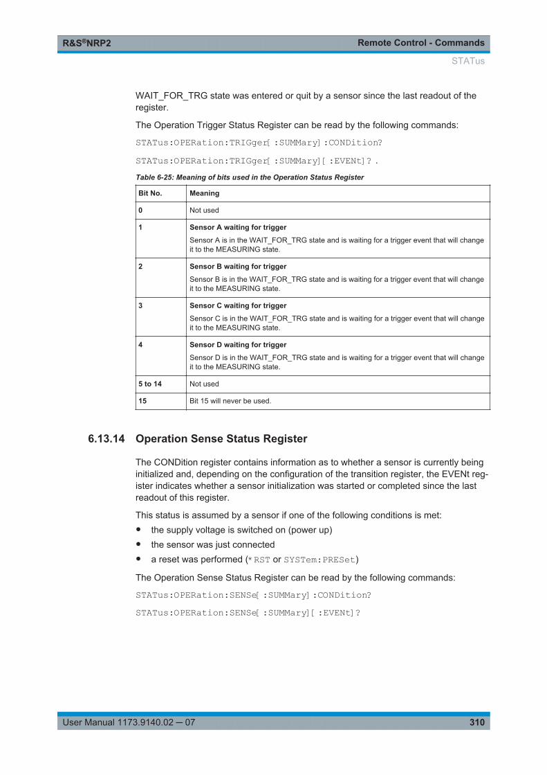
Remote Control - CommandsR&S®NRP2
310User Manual 1173.9140.02 ─ 07
WAIT_FOR_TRG state was entered or quit by a sensor since the last readout of theregister.
The Operation Trigger Status Register can be read by the following commands:
STATus:OPERation:TRIGger[:SUMMary]:CONDition? STATus:OPERation:TRIGger[:SUMMary][:EVENt]? .
Table 6-25: Meaning of bits used in the Operation Status Register
Bit No. Meaning
0 Not used
1 Sensor A waiting for trigger
Sensor A is in the WAIT_FOR_TRG state and is waiting for a trigger event that will changeit to the MEASURING state.
2 Sensor B waiting for trigger
Sensor B is in the WAIT_FOR_TRG state and is waiting for a trigger event that will changeit to the MEASURING state.
3 Sensor C waiting for trigger
Sensor C is in the WAIT_FOR_TRG state and is waiting for a trigger event that will changeit to the MEASURING state.
4 Sensor D waiting for trigger
Sensor D is in the WAIT_FOR_TRG state and is waiting for a trigger event that will changeit to the MEASURING state.
5 to 14 Not used
15 Bit 15 will never be used.
6.13.14 Operation Sense Status Register
The CONDition register contains information as to whether a sensor is currently beinginitialized and, depending on the configuration of the transition register, the EVENt reg-ister indicates whether a sensor initialization was started or completed since the lastreadout of this register.
This status is assumed by a sensor if one of the following conditions is met:● the supply voltage is switched on (power up)● the sensor was just connected● a reset was performed (*RST or SYSTem:PRESet)
The Operation Sense Status Register can be read by the following commands:
STATus:OPERation:SENSe[:SUMMary]:CONDition?STATus:OPERation:SENSe[:SUMMary][:EVENt]?
STATus
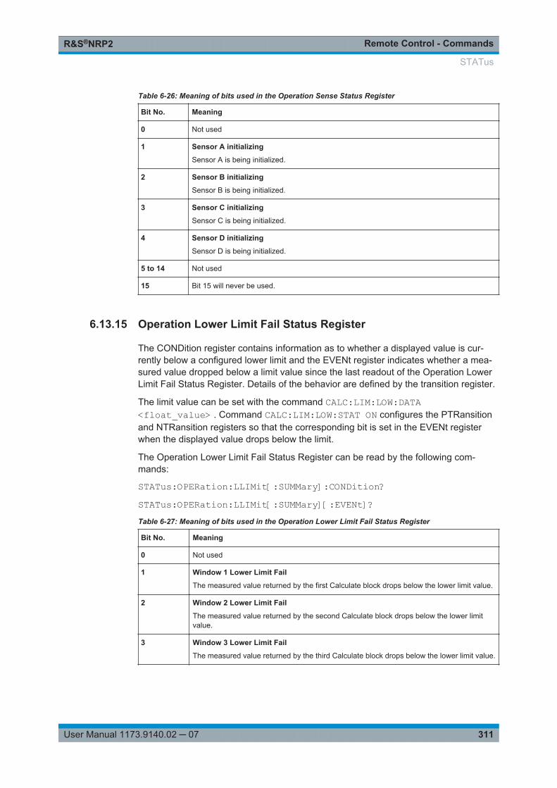
Remote Control - CommandsR&S®NRP2
311User Manual 1173.9140.02 ─ 07
Table 6-26: Meaning of bits used in the Operation Sense Status Register
Bit No. Meaning
0 Not used
1 Sensor A initializing
Sensor A is being initialized.
2 Sensor B initializing
Sensor B is being initialized.
3 Sensor C initializing
Sensor C is being initialized.
4 Sensor D initializing
Sensor D is being initialized.
5 to 14 Not used
15 Bit 15 will never be used.
6.13.15 Operation Lower Limit Fail Status Register
The CONDition register contains information as to whether a displayed value is cur-rently below a configured lower limit and the EVENt register indicates whether a mea-sured value dropped below a limit value since the last readout of the Operation LowerLimit Fail Status Register. Details of the behavior are defined by the transition register.
The limit value can be set with the command CALC:LIM:LOW:DATA<float_value> . Command CALC:LIM:LOW:STAT ON configures the PTRansitionand NTRansition registers so that the corresponding bit is set in the EVENt registerwhen the displayed value drops below the limit.
The Operation Lower Limit Fail Status Register can be read by the following com-mands:
STATus:OPERation:LLIMit[:SUMMary]:CONDition?STATus:OPERation:LLIMit[:SUMMary][:EVENt]?Table 6-27: Meaning of bits used in the Operation Lower Limit Fail Status Register
Bit No. Meaning
0 Not used
1 Window 1 Lower Limit Fail
The measured value returned by the first Calculate block drops below the lower limit value.
2 Window 2 Lower Limit Fail
The measured value returned by the second Calculate block drops below the lower limitvalue.
3 Window 3 Lower Limit Fail
The measured value returned by the third Calculate block drops below the lower limit value.
STATus
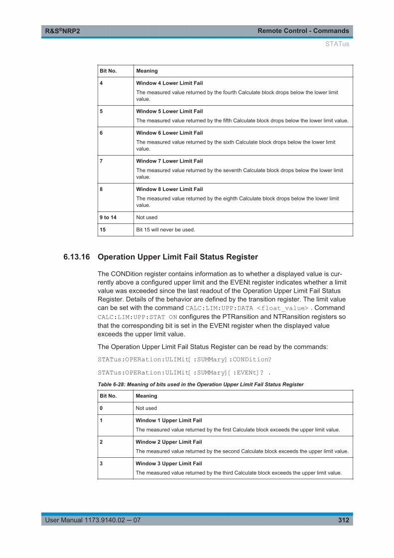
Remote Control - CommandsR&S®NRP2
312User Manual 1173.9140.02 ─ 07
Bit No. Meaning
4 Window 4 Lower Limit Fail
The measured value returned by the fourth Calculate block drops below the lower limitvalue.
5 Window 5 Lower Limit Fail
The measured value returned by the fifth Calculate block drops below the lower limit value.
6 Window 6 Lower Limit Fail
The measured value returned by the sixth Calculate block drops below the lower limitvalue.
7 Window 7 Lower Limit Fail
The measured value returned by the seventh Calculate block drops below the lower limitvalue.
8 Window 8 Lower Limit Fail
The measured value returned by the eighth Calculate block drops below the lower limitvalue.
9 to 14 Not used
15 Bit 15 will never be used.
6.13.16 Operation Upper Limit Fail Status Register
The CONDition register contains information as to whether a displayed value is cur-rently above a configured upper limit and the EVENt register indicates whether a limitvalue was exceeded since the last readout of the Operation Upper Limit Fail StatusRegister. Details of the behavior are defined by the transition register. The limit valuecan be set with the command CALC:LIM:UPP:DATA <float_value> . CommandCALC:LIM:UPP:STAT ON configures the PTRansition and NTRansition registers sothat the corresponding bit is set in the EVENt register when the displayed valueexceeds the upper limit value.
The Operation Upper Limit Fail Status Register can be read by the commands:
STATus:OPERation:ULIMit[:SUMMary]:CONDition?STATus:OPERation:ULIMit[:SUMMary][:EVENt]? .
Table 6-28: Meaning of bits used in the Operation Upper Limit Fail Status Register
Bit No. Meaning
0 Not used
1 Window 1 Upper Limit Fail
The measured value returned by the first Calculate block exceeds the upper limit value.
2 Window 2 Upper Limit Fail
The measured value returned by the second Calculate block exceeds the upper limit value.
3 Window 3 Upper Limit Fail
The measured value returned by the third Calculate block exceeds the upper limit value.
STATus
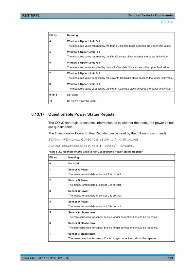
Remote Control - CommandsR&S®NRP2
313User Manual 1173.9140.02 ─ 07
Bit No. Meaning
4 Window 4 Upper Limit Fail
The measured value returned by the fourth Calculate block exceeds the upper limit value.
5 Window 5 Upper Limit Fail
The measured value returned by the fifth Calculate block exceeds the upper limit value.
6 Window 6 Upper Limit Fail
The measured value supplied by the sixth Calculate block exceeds the upper limit value.
7 Window 7 Upper Limit Fail
The measured value supplied by the seventh Calculate block exceeds the upper limit value.
8 Window 8 Upper Limit Fail
The measured value supplied by the eighth Calculate block exceeds the upper limit value.
9 to14 Not used
15 Bit 15 will never be used.
6.13.17 Questionable Power Status Register
The CONDition register contains information as to whether the measured power valuesare questionable.
The Questionable Power Status Register can be read by the following commands:
STATus:QUEStionable:POWer[:SUMMary]:CONDition?STATus:QUEStionable:POWer[:SUMMary][:EVENt]?Table 6-29: Meaning of bits used in the Questionable Power Status Register
Bit No. Meaning
0 Not used
1 Sensor A Power
The measurement data of sensor A is corrupt.
2 Sensor B Power
The measurement data of sensor B is corrupt.
3 Sensor C Power
The measurement data of sensor C is corrupt.
4 Sensor D Power
The measurement data of sensor D is corrupt.
5 Sensor A please zero
The zero correction for sensor A is no longer correct and should be repeated.
6 Sensor B please zero
The zero correction for sensor B is no longer correct and should be repeated.
7 Sensor C please zero
The zero correction for sensor C is no longer correct and should be repeated.
STATus
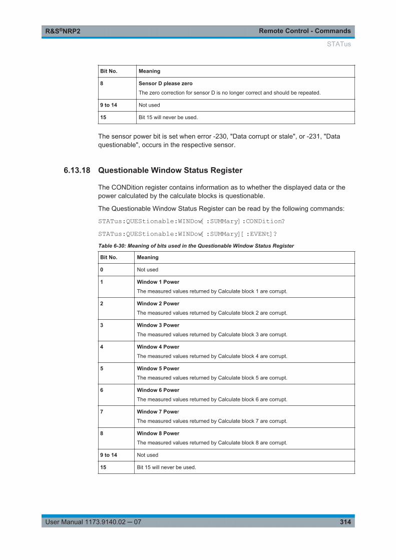
Remote Control - CommandsR&S®NRP2
314User Manual 1173.9140.02 ─ 07
Bit No. Meaning
8 Sensor D please zero
The zero correction for sensor D is no longer correct and should be repeated.
9 to 14 Not used
15 Bit 15 will never be used.
The sensor power bit is set when error -230, "Data corrupt or stale", or -231, "Dataquestionable", occurs in the respective sensor.
6.13.18 Questionable Window Status Register
The CONDition register contains information as to whether the displayed data or thepower calculated by the calculate blocks is questionable.
The Questionable Window Status Register can be read by the following commands:
STATus:QUEStionable:WINDow[:SUMMary]:CONDition?STATus:QUEStionable:WINDow[:SUMMary][:EVENt]?Table 6-30: Meaning of bits used in the Questionable Window Status Register
Bit No. Meaning
0 Not used
1 Window 1 Power
The measured values returned by Calculate block 1 are corrupt.
2 Window 2 Power
The measured values returned by Calculate block 2 are corrupt.
3 Window 3 Power
The measured values returned by Calculate block 3 are corrupt.
4 Window 4 Power
The measured values returned by Calculate block 4 are corrupt.
5 Window 5 Power
The measured values returned by Calculate block 5 are corrupt.
6 Window 6 Power
The measured values returned by Calculate block 6 are corrupt.
7 Window 7 Power
The measured values returned by Calculate block 7 are corrupt.
8 Window 8 Power
The measured values returned by Calculate block 8 are corrupt.
9 to 14 Not used
15 Bit 15 will never be used.
STATus
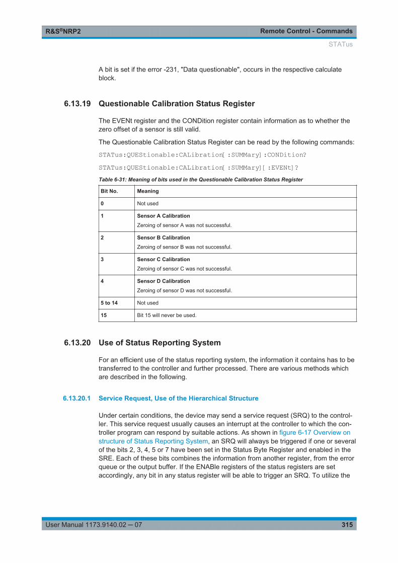
Remote Control - CommandsR&S®NRP2
315User Manual 1173.9140.02 ─ 07
A bit is set if the error -231, "Data questionable", occurs in the respective calculateblock.
6.13.19 Questionable Calibration Status Register
The EVENt register and the CONDition register contain information as to whether thezero offset of a sensor is still valid.
The Questionable Calibration Status Register can be read by the following commands:
STATus:QUEStionable:CALibration[:SUMMary]:CONDition?STATus:QUEStionable:CALibration[:SUMMary][:EVENt]?Table 6-31: Meaning of bits used in the Questionable Calibration Status Register
Bit No. Meaning
0 Not used
1 Sensor A Calibration
Zeroing of sensor A was not successful.
2 Sensor B Calibration
Zeroing of sensor B was not successful.
3 Sensor C Calibration
Zeroing of sensor C was not successful.
4 Sensor D Calibration
Zeroing of sensor D was not successful.
5 to 14 Not used
15 Bit 15 will never be used.
6.13.20 Use of Status Reporting System
For an efficient use of the status reporting system, the information it contains has to betransferred to the controller and further processed. There are various methods whichare described in the following.
6.13.20.1 Service Request, Use of the Hierarchical Structure
Under certain conditions, the device may send a service request (SRQ) to the control-ler. This service request usually causes an interrupt at the controller to which the con-troller program can respond by suitable actions. As shown in figure 6-17 Overview onstructure of Status Reporting System, an SRQ will always be triggered if one or severalof the bits 2, 3, 4, 5 or 7 have been set in the Status Byte Register and enabled in theSRE. Each of these bits combines the information from another register, from the errorqueue or the output buffer. If the ENABle registers of the status registers are setaccordingly, any bit in any status register will be able to trigger an SRQ. To utilize the
STATus
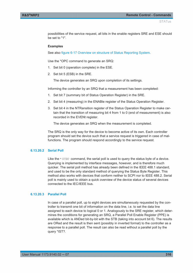
Remote Control - CommandsR&S®NRP2
316User Manual 1173.9140.02 ─ 07
possibilities of the service request, all bits in the enable registers SRE and ESE shouldbe set to "1".
Examples
See also figure 6-17 Overview on structure of Status Reporting System.
Use the *OPC command to generate an SRQ:
1. Set bit 0 (operation complete) in the ESE.
2. Set bit 5 (ESB) in the SRE.
The device generates an SRQ upon completion of its settings.
Informing the controller by an SRQ that a measurement has been completed:
1. Set bit 7 (summary bit of Status Operation Register) in the SRE.
2. Set bit 4 (measuring) in the ENABle register of the Status Operation Register.
3. Set bit 4 in the NTRansition register of the Status Operation Register to make cer-tain that the transition of measuring bit 4 from 1 to 0 (end of measurement) is alsorecorded in the EVENt register.
The device generates an SRQ when the measurement is completed.
The SRQ is the only way for the device to become active of its own. Each controllerprogram should set the device such that a service request is triggered in case of mal-functions. The program should respond accordingly to the service request.
6.13.20.2 Serial Poll
Like the *STB? command, the serial poll is used to query the status byte of a device.Querying is implemented by interface messages, however, and is therefore muchquicker. The serial poll method has already been defined in the IEEE 488.1 standard,and used to be the only standard method of querying the Status Byte Register. Thismethod also works with devices that conform neither to SCPI nor to IEEE 488.2. Serialpoll is mainly used to obtain a quick overview of the device status of several devicesconnected to the IEC/IEEE bus.
6.13.20.3 Parallel Poll
In case of a parallel poll, up to eight devices are simultaneously requested by the con-troller to transmit one bit of information on the data line, i.e. to set the data lineassigned to each device to logical 0 or 1. Analogously to the SRE register, which deter-mines the conditions for generating an SRQ, a Parallel Poll Enable Register (PPE) isavailable which is ANDed bit-by-bit with the STB (taking into account bit 6). The resultsare ORed and the result is then sent (possibly in inverted format) to the controller as aresponse to a parallel poll. The result can also be read without a parallel poll by thequery *IST?.
STATus
Remote Control - CommandsR&S®NRP2
317User Manual 1173.9140.02 ─ 07
The parallel poll mode is mainly used to quickly find out which of the many devicesconnected to the IEC/IEEE bus caused an SRQ. For this purpose, SRE and PPE mustbe set to the same value.
6.13.20.4 Queries
Each part of a status register can be read out by queries. The queries are specified inthe description of the SCPI commands (command system STATus). The queriesalways yield a number representing the bit pattern of the queried register. This numberis evaluated by the controller program.
Queries are mainly used after an SRQ to obtain detailed information about the causeof the SRQ.
6.13.20.5 Error Queue Query
Each error in the device causes an entry in the error queue. The entries in the errorqueue are error messages in plain text. If a sensor is connected, sensor-specific errorscan be seen via manual control in the menu File(Error List or in remote control via"Error List...". Usually, the error queue is read with the SCPI query SYSTem:ERRor?.Each SYSTem:ERRor? query is answered by an entry from the error queue. If thereare no more error messages in the error queue, 0 = "No error" is returned by thedevice.
The error queue should be queried in the controller program after each SRQ since thequeue entries provide a more precise description of the error cause than the statusregisters. In particular, in the test phase of a controller program the error queue shouldbe queried at regular intervals since it also registers faulty commands from the control-ler to the device.
6.13.21 Initialization of the SCPI Status Registers
The commands *RST, *DCL and SYSTem:PRESet as well as powering on the devicealso affect the status reporting system. Initialization of device status, table 6-32, con-tains the various commands and events causing a reset of the status reporting system.None of the commands, with the exception of *RST and SYSTem:PRESet, affects thefunctional device settings. In particular, DCL does not clear the device settings.
STATus

Remote Control - CommandsR&S®NRP2
318User Manual 1173.9140.02 ─ 07
Table 6-32: Initialization of device status
Result Power On DCL, SDC
(DeviceClear,SelectedDeviceClear)
*RST or
SYSTem:PRESet
STATus:PRESet
*CLS
Power-On-StatusClear(*PSC)
Effect 0 1
Clear STB (Status Byte) and
ESR (Standard Event Status Register)
-- yes -- -- -- yes
Clear SRE (Service Request Enable)and
ESE (Standard Event Status Enable)
-- yes -- -- -- --
Clear PPE (Parallel Poll Enable) -- yes -- -- -- --
Clear EVENt register -- yes -- -- -- yes
Clear ENABle register of all OPERationand
QUEStionable registers
-- yes -- -- yes --
Fill PTRansition register with "1",
delete NTRansition register
-- yes -- -- yes --
Clear error/event queue yes yes -- -- -- yes
Clear output queue yes yes yes 1) 1) 1)
Stop command processing (parser) and
clear input queue
yes yes yes -- -- --
1): Any command sent to a non-empty output queue causes the error:
-410 "Query interrupted"
6.14 SYSTem
With the aid of the SYSTem command system, administrative device settings can bemade and queried.
This includes:● list of error messages● IEC/IEEE-bus address● resetting the R&S NRP2● setting the date and time● audible signals● version numbers of hardware and software● setting the system speed
SYSTem
Remote Control - CommandsR&S®NRP2
319User Manual 1173.9140.02 ─ 07
SYSTem:BEEPer[:IMMediate]......................................................................................... 319SYSTem:BEEPer:NOTify:OVERload................................................................................319SYSTem:BEEPer:NOTify:KEY.........................................................................................320SYSTem:BEEPer:STOP................................................................................................. 320SYSTem:BEEPer:TIME.................................................................................................. 320SYSTem:COMMunicate:GPIB[:SELF]:ADDRess............................................................... 320SYSTem:COMMunicate:INET:MODE...............................................................................320SYSTem:COMMunicate:INET[:SELF]:ADDRess............................................................... 321SYSTem:COMMunicate:INET[:SELF]:GATEway:ADDRess................................................ 321SYSTem:COMMunicate:INET[:SELF]:SUBNetmask:ADDRess........................................... 321SYSTem:DATE..............................................................................................................322SYSTem:IDN.................................................................................................................322SYSTem:IDN:AUTO.......................................................................................................322SYSTem:INFO?.............................................................................................................322SYSTem:ERRor?...........................................................................................................323SYSTem:ERRor:EXTended[:STATe]................................................................................323SYSTem:KEY................................................................................................................324SYSTem:LANGuage...................................................................................................... 325SYSTem:OPT................................................................................................................325SYSTem:OPT:AUTO......................................................................................................325SYSTem:PRESet...........................................................................................................325SYSTem:REBoot........................................................................................................... 325SYSTem:SENSor<[1]..4>:INFO?..................................................................................... 326SYSTem:SENSor<[1]..4>:REBoot....................................................................................326SYSTem:SENSor<[1]..4>:RESet..................................................................................... 326SYSTem:SENSor<[1]..4>:TEST?.....................................................................................326SYSTem:SPEed............................................................................................................ 326SYSTem:STANdard:CATalog?........................................................................................327SYSTem:STANdard:PRESet...........................................................................................327SYSTem:STANdard:PWSettings..................................................................................... 327SYSTem:STANdard:TRIGger:SOURce............................................................................ 327SYSTem:TIME...............................................................................................................327SYSTem:VERSion?....................................................................................................... 328
SYSTem:BEEPer[:IMMediate]
Generates an audible signal via the built-in loudspeaker. The duration of the signal isset with SYST:BEEP:TIME. Frequency and volume cannot be changed. The signal isonly output if it is not switched off with SYS:BEEP:STAT OFF.
Usage: Event
SYSTem:BEEPer:NOTify:OVERload <state>
Determines if the R&S NRP2 shall emit an acoustic signal when the power at a sensorexceeds the power limit.
Parameters:<state> ON | OFF
*RST: OFF
SYSTem

Remote Control - CommandsR&S®NRP2
320User Manual 1173.9140.02 ─ 07
Usage: Event
SYSTem:BEEPer:NOTify:KEY <state>
Enables (ON) or disables (OFF) acoustic key clicks, respectively.
Parameters:<state> ON | OFF
*RST: OFF
SYSTem:BEEPer:STOP
Stops the output of an audible signal.
Usage: Event
SYSTem:BEEPer:TIME <nrf>
Sets the length in milliseconds of the audible signal output with SYS:BEEP.
Parameters:<nrf> int_value
Range: 1...60*RST: This setting is not changed by *RST.Default unit: S
SYSTem:COMMunicate:GPIB[:SELF]:ADDRess <nr1>
Sets the address with which the R&S NRP2 can be addressed via the IEC/IEEE bus.The address is factory-set to 20 and is not changed by a reset.
Parameters:<nr1> int_value
Range: 0...30*RST: This setting is not changed by *RST.
Usage: Event
SYSTem:COMMunicate:INET:MODE <mode>
Selects the mode for transmitting the special control sequences via ethernet accordingto draft IEEE 1174.
Parameter Mode
0 no control sequences (abbr.: 1174.0 mode)
1 the IEC/IEEE 488.1 mode (abbr.: 1174.1 mode)
2 the IEC/IEEE 488.2 mode (abbr.: 1174.2 mode)
SYSTem
Remote Control - CommandsR&S®NRP2
321User Manual 1173.9140.02 ─ 07
Parameters:<state> 0 | 1 | 2
*RST: This setting is not changed by *RST.
SYSTem:COMMunicate:INET[:SELF]:ADDRess <ip1>,<ip2>,<ip3>,<ip4>
Sets the IP address of the R&S NRP2.
Note: This command cannot be used, while VXI11 or Ethernet is in use.
Note: Choosing an invalid IP-Address may disturb the traffic on your LAN. If you arenot sure how to configure these settings, please ask your network administrator.
Parameters:<ip1>,<ip2>,<ip3>,<ip4>int_values
The four parameter form the IP address<ip1>.<ip2>.<ip3>.<ip4>. For example, IP address 104.0.0.255is entered as SYSTem:COMMunicate:INET:ADDRess108,0,0,255.
Range: 0...255 for each part of the IP address*RST: This setting is not changed by *RST.
Usage: Event
SYSTem:COMMunicate:INET[:SELF]:GATEway:ADDRess<gwip1>,<gwip2>,<gwip3>,<gwip4>
Sets the gateway address of your local subnet.
Note: This command cannot be used, while VXI11 or Ethernet is in use.
Note: Choosing an invalid Gateway-Address may disturb the traffic on your LAN. If youare not sure how to configure these settings, please ask your network administrator.
Parameters:<gwip1...4> int_value
Range: 0...255*RST: This setting is not changed by *RST.
Usage: Event
SYSTem:COMMunicate:INET[:SELF]:SUBNetmask:ADDRess<sm1>,<sm2>,<sm3>,<sm4>
Sets the subnet mask of your local subnet.
Note: This command cannot be used, while VXI11 or Ethernet is in use.
Note: Choosing an invalid subnet mask address may disturb the traffic on your LAN. Ifyou are not sure how to configure these settings, please ask your network administra-tor.
SYSTem
Remote Control - CommandsR&S®NRP2
322User Manual 1173.9140.02 ─ 07
Parameters:<sm1...4> int_value
Range: 0...255*RST: This setting is not changed by *RST.
Usage: Event
SYSTem:DATE <year>,<month>,<day>
Sets the date. Since the R&S NRP2 has no battery-backed clock, the date has to bereset if the clock was not set after the last power-on of the R&S NRP2.
The date is set in the format yyyy,(m)m,(d)d. This setting is not changed by *RST.
Table 6-33: Parameter range
Parameter Value range
<year> 2000 ... 2100
<month> 1 (January) ... 12 (December)
<day> 1 ... 31
SYSTem:IDN <string>
Determines the user defined return value for the *IDN query. The maximum stringlength is 128 characters.
SYSTem:IDN:AUTO <state>
Activates/deactivates return of the user-defined string for the *IDN query.
SYSTem:INFO? <string>
Returns information about the system. <string_value> is used to query a specificinformation item. If called without parameters, the command returns all available infor-mation in the form of a list of strings separated by commas. <string_value> canhave the following values. No difference is made between upper-case and lower-caseletters:
<string_value> Meaning
"Manufacturer" Manufacturer of device
"Type" Type (R&S NRP2)
"Stock Number" Order No. of R&S NRP2
"Serial" Serial number
"HWVersion" Hardware version
"SW Build" Firmware version
SYSTem
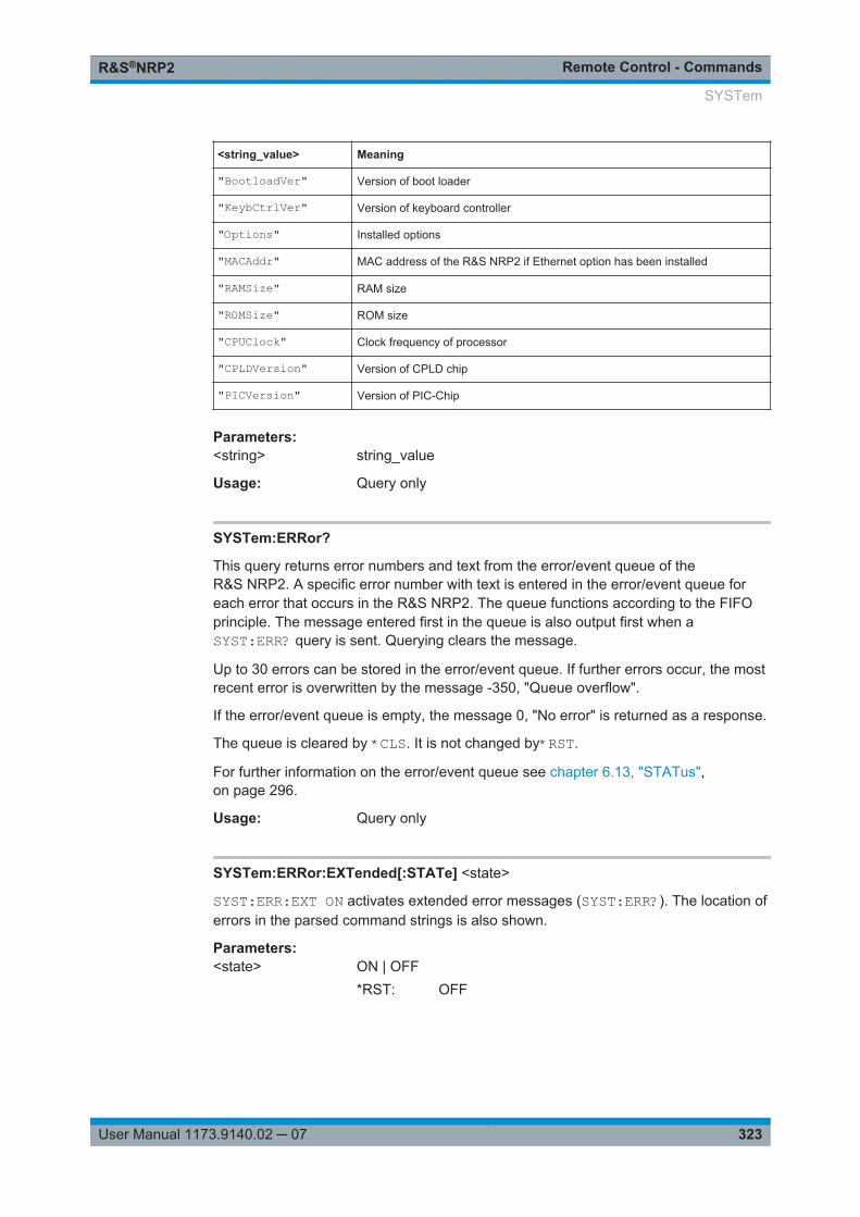
Remote Control - CommandsR&S®NRP2
323User Manual 1173.9140.02 ─ 07
<string_value> Meaning
"BootloadVer" Version of boot loader
"KeybCtrlVer" Version of keyboard controller
"Options" Installed options
"MACAddr" MAC address of the R&S NRP2 if Ethernet option has been installed
"RAMSize" RAM size
"ROMSize" ROM size
"CPUClock" Clock frequency of processor
"CPLDVersion" Version of CPLD chip
"PICVersion" Version of PIC-Chip
Parameters:<string> string_value
Usage: Query only
SYSTem:ERRor?
This query returns error numbers and text from the error/event queue of theR&S NRP2. A specific error number with text is entered in the error/event queue foreach error that occurs in the R&S NRP2. The queue functions according to the FIFOprinciple. The message entered first in the queue is also output first when aSYST:ERR? query is sent. Querying clears the message.
Up to 30 errors can be stored in the error/event queue. If further errors occur, the mostrecent error is overwritten by the message -350, "Queue overflow".
If the error/event queue is empty, the message 0, "No error" is returned as a response.
The queue is cleared by *CLS. It is not changed by*RST.
For further information on the error/event queue see chapter 6.13, "STATus",on page 296.
Usage: Query only
SYSTem:ERRor:EXTended[:STATe] <state>
SYST:ERR:EXT ON activates extended error messages (SYST:ERR?). The location oferrors in the parsed command strings is also shown.
Parameters:<state> ON | OFF
*RST: OFF
SYSTem
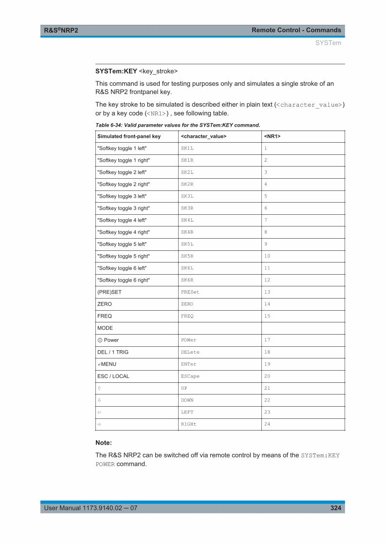
Remote Control - CommandsR&S®NRP2
324User Manual 1173.9140.02 ─ 07
SYSTem:KEY <key_stroke>
This command is used for testing purposes only and simulates a single stroke of anR&S NRP2 frontpanel key.
The key stroke to be simulated is described either in plain text (<character_value>)or by a key code (<NR1>) , see following table.
Table 6-34: Valid parameter values for the SYSTem:KEY command.
Simulated front-panel key <character_value> <NR1>
"Softkey toggle 1 left" SK1L 1
"Softkey toggle 1 right" SK1R 2
"Softkey toggle 2 left" SK2L 3
"Softkey toggle 2 right" SK2R 4
"Softkey toggle 3 left" SK3L 5
"Softkey toggle 3 right" SK3R 6
"Softkey toggle 4 left" SK4L 7
"Softkey toggle 4 right" SK4R 8
"Softkey toggle 5 left" SK5L 9
"Softkey toggle 5 right" SK5R 10
"Softkey toggle 6 left" SK6L 11
"Softkey toggle 6 right" SK6R 12
(PRE)SET PRESet 13
ZERO ZERO 14
FREQ FREQ 15
MODE
Ⓘ Power POWer 17
DEL / 1 TRIG DELete 18
↵MENU ENTer 19
ESC / LOCAL ESCape 20
⇧ UP 21
⇩ DOWN 22
⇦ LEFT 23
⇨ RIGHt 24
Note:
The R&S NRP2 can be switched off via remote control by means of the SYSTem:KEYPOWER command.
SYSTem
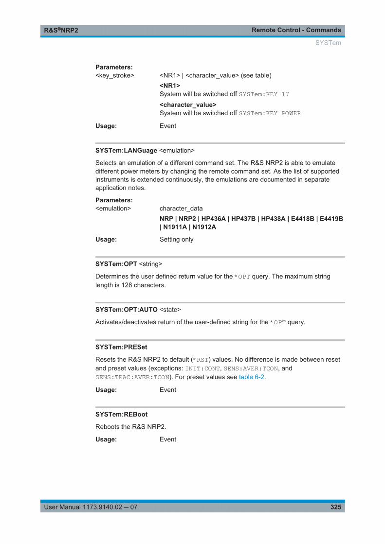
Remote Control - CommandsR&S®NRP2
325User Manual 1173.9140.02 ─ 07
Parameters:<key_stroke> <NR1> | <character_value> (see table)
<NR1>System will be switched off SYSTem:KEY 17<character_value>System will be switched off SYSTem:KEY POWER
Usage: Event
SYSTem:LANGuage <emulation>
Selects an emulation of a different command set. The R&S NRP2 is able to emulatedifferent power meters by changing the remote command set. As the list of supportedinstruments is extended continuously, the emulations are documented in separateapplication notes.
Parameters:<emulation> character_data
NRP | NRP2 | HP436A | HP437B | HP438A | E4418B | E4419B| N1911A | N1912A
Usage: Setting only
SYSTem:OPT <string>
Determines the user defined return value for the *OPT query. The maximum stringlength is 128 characters.
SYSTem:OPT:AUTO <state>
Activates/deactivates return of the user-defined string for the *OPT query.
SYSTem:PRESet
Resets the R&S NRP2 to default (*RST) values. No difference is made between resetand preset values (exceptions: INIT:CONT, SENS:AVER:TCON, andSENS:TRAC:AVER:TCON). For preset values see table 6-2.
Usage: Event
SYSTem:REBoot
Reboots the R&S NRP2.
Usage: Event
SYSTem
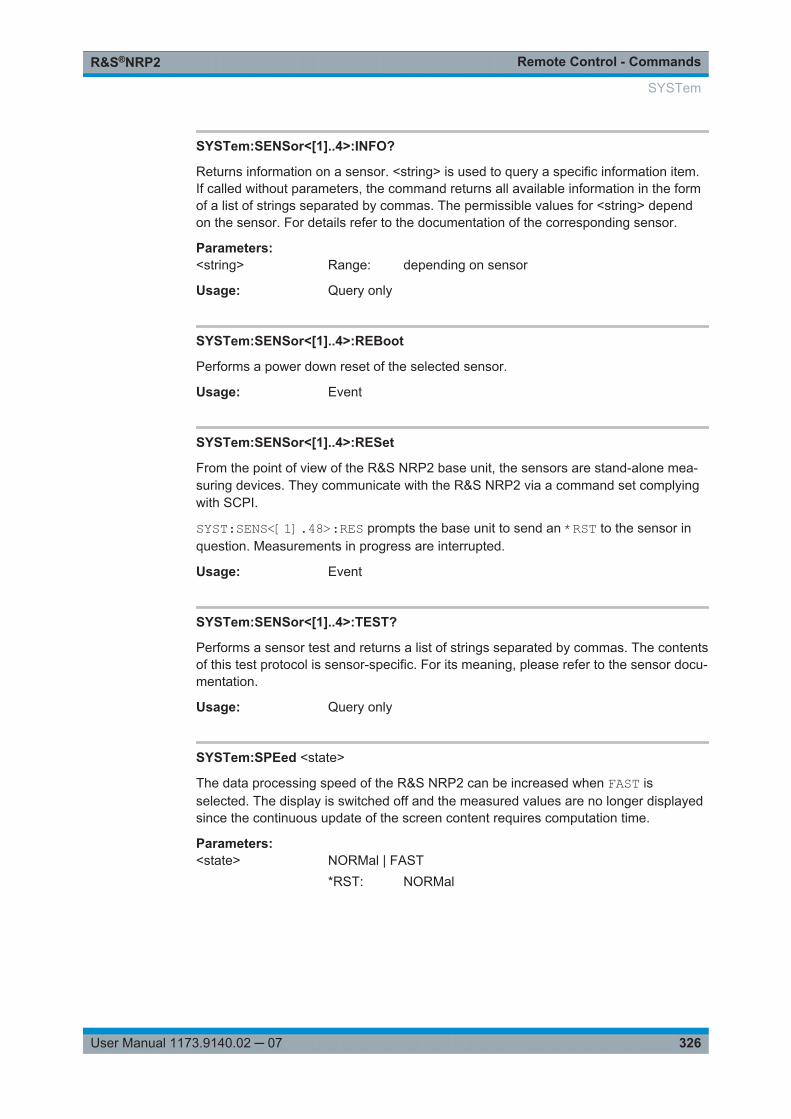
Remote Control - CommandsR&S®NRP2
326User Manual 1173.9140.02 ─ 07
SYSTem:SENSor<[1]..4>:INFO?
Returns information on a sensor. <string> is used to query a specific information item.If called without parameters, the command returns all available information in the formof a list of strings separated by commas. The permissible values for <string> dependon the sensor. For details refer to the documentation of the corresponding sensor.
Parameters:<string> Range: depending on sensor
Usage: Query only
SYSTem:SENSor<[1]..4>:REBoot
Performs a power down reset of the selected sensor.
Usage: Event
SYSTem:SENSor<[1]..4>:RESet
From the point of view of the R&S NRP2 base unit, the sensors are stand-alone mea-suring devices. They communicate with the R&S NRP2 via a command set complyingwith SCPI.
SYST:SENS<[1].48>:RES prompts the base unit to send an *RST to the sensor inquestion. Measurements in progress are interrupted.
Usage: Event
SYSTem:SENSor<[1]..4>:TEST?
Performs a sensor test and returns a list of strings separated by commas. The contentsof this test protocol is sensor-specific. For its meaning, please refer to the sensor docu-mentation.
Usage: Query only
SYSTem:SPEed <state>
The data processing speed of the R&S NRP2 can be increased when FAST isselected. The display is switched off and the measured values are no longer displayedsince the continuous update of the screen content requires computation time.
Parameters:<state> NORMal | FAST
*RST: NORMal
SYSTem
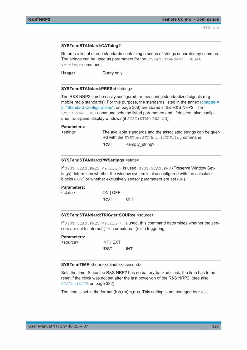
Remote Control - CommandsR&S®NRP2
327User Manual 1173.9140.02 ─ 07
SYSTem:STANdard:CATalog?
Returns a list of stored standards containing a series of strings separated by commas.The strings can be used as parameters for theSYSTem:STANdard:PRESet<string> command.
Usage: Query only
SYSTem:STANdard:PRESet <string>
The R&S NRP2 can be easily configured for measuring standardized signals (e.g.mobile radio standards). For this purpose, the standards listed in the annex (chapter A.3, "Standard Configurations", on page 368) are stored in the R&S NRP2. TheSYST:STAN:PRES command sets the listed parameters and, if desired, also config-ures front-panel display windows (if SYST:STAN:PWS ON).
Parameters:<string> The available standards and the associated strings can be quer-
ied with the SYSTem:STANdard:CATalog command.
*RST: <empty_string>
SYSTem:STANdard:PWSettings <state>
If SYST:STAN:PRES <string> is used, SYST:STAN:PWS (Preserve Window Set-tings) determines whether the window system is also configured with the calculateblocks (OFF) or whether exclusively sensor parameters are set (ON).
Parameters:<state> ON | OFF
*RST: OFF
SYSTem:STANdard:TRIGger:SOURce <source>
If SYST:STAN:PRES <string> is used, this command determines whether the sen-sors are set to internal (INT) or external (EXT) triggering.
Parameters:<source> INT | EXT
*RST: INT
SYSTem:TIME <hour>,<minute>,<second>
Sets the time. Since the R&S NRP2 has no battery-backed clock, the time has to bereset if the clock was not set after the last power-on of the R&S NRP2. (see alsoSYSTem:DATE on page 322).
The time is set in the format (h)h,(m)m,(s)s. This setting is not changed by *RST.
SYSTem
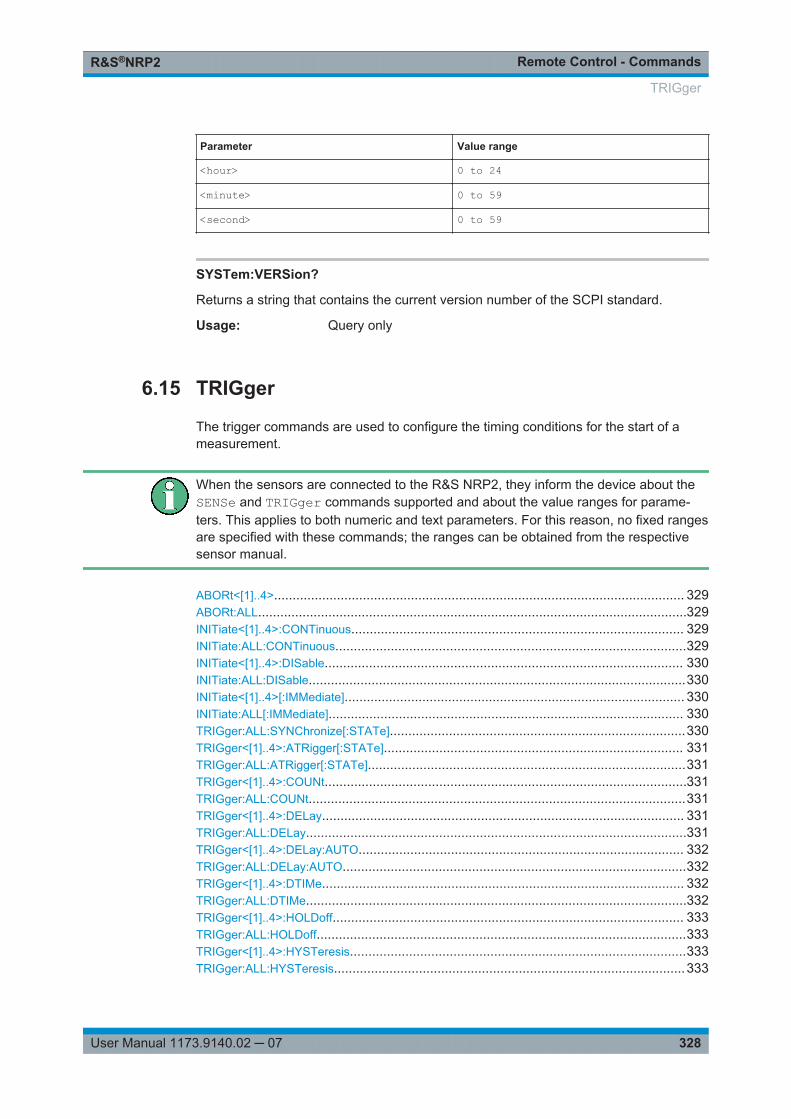
Remote Control - CommandsR&S®NRP2
328User Manual 1173.9140.02 ─ 07
Parameter Value range
<hour> 0 to 24
<minute> 0 to 59
<second> 0 to 59
SYSTem:VERSion?
Returns a string that contains the current version number of the SCPI standard.
Usage: Query only
6.15 TRIGger
The trigger commands are used to configure the timing conditions for the start of ameasurement.
When the sensors are connected to the R&S NRP2, they inform the device about theSENSe and TRIGger commands supported and about the value ranges for parame-ters. This applies to both numeric and text parameters. For this reason, no fixed rangesare specified with these commands; the ranges can be obtained from the respectivesensor manual.
ABORt<[1]..4>............................................................................................................... 329ABORt:ALL....................................................................................................................329INITiate<[1]..4>:CONTinuous.......................................................................................... 329INITiate:ALL:CONTinuous...............................................................................................329INITiate<[1]..4>:DISable................................................................................................. 330INITiate:ALL:DISable......................................................................................................330INITiate<[1]..4>[:IMMediate]............................................................................................ 330INITiate:ALL[:IMMediate]................................................................................................ 330TRIGger:ALL:SYNChronize[:STATe]................................................................................330TRIGger<[1]..4>:ATRigger[:STATe]................................................................................. 331TRIGger:ALL:ATRigger[:STATe]......................................................................................331TRIGger<[1]..4>:COUNt..................................................................................................331TRIGger:ALL:COUNt......................................................................................................331TRIGger<[1]..4>:DELay.................................................................................................. 331TRIGger:ALL:DELay.......................................................................................................331TRIGger<[1]..4>:DELay:AUTO........................................................................................ 332TRIGger:ALL:DELay:AUTO.............................................................................................332TRIGger<[1]..4>:DTIMe.................................................................................................. 332TRIGger:ALL:DTIMe.......................................................................................................332TRIGger<[1]..4>:HOLDoff............................................................................................... 333TRIGger:ALL:HOLDoff....................................................................................................333TRIGger<[1]..4>:HYSTeresis...........................................................................................333TRIGger:ALL:HYSTeresis...............................................................................................333
TRIGger
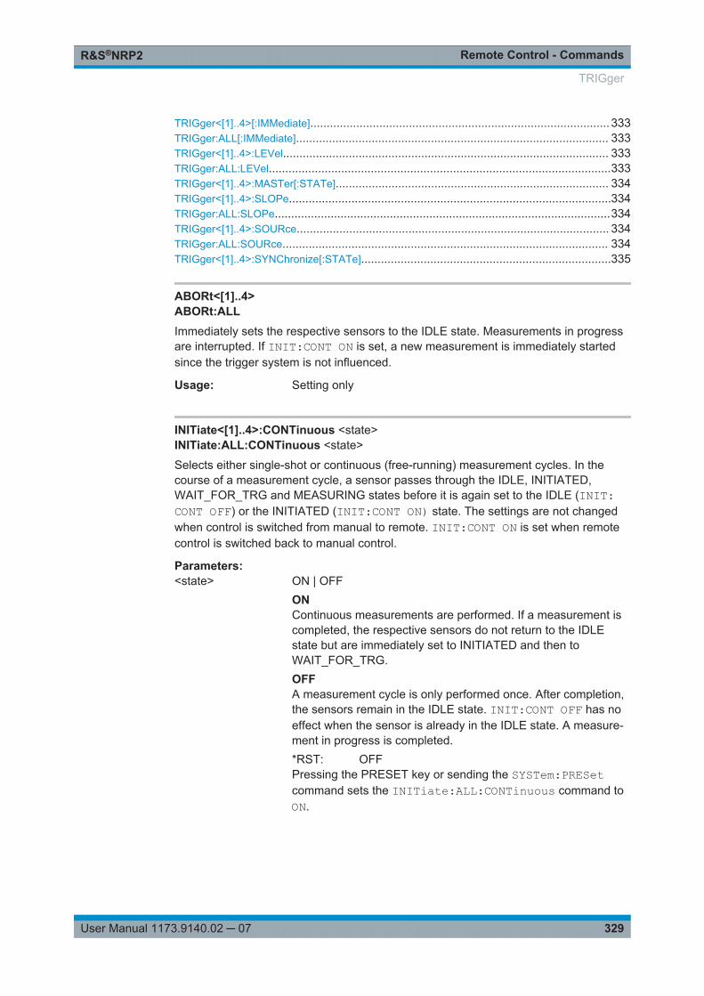
Remote Control - CommandsR&S®NRP2
329User Manual 1173.9140.02 ─ 07
TRIGger<[1]..4>[:IMMediate]........................................................................................... 333TRIGger:ALL[:IMMediate]............................................................................................... 333TRIGger<[1]..4>:LEVel................................................................................................... 333TRIGger:ALL:LEVel........................................................................................................333TRIGger<[1]..4>:MASTer[:STATe]................................................................................... 334TRIGger<[1]..4>:SLOPe..................................................................................................334TRIGger:ALL:SLOPe......................................................................................................334TRIGger<[1]..4>:SOURce............................................................................................... 334TRIGger:ALL:SOURce................................................................................................... 334TRIGger<[1]..4>:SYNChronize[:STATe]............................................................................335
ABORt<[1]..4>ABORt:ALLImmediately sets the respective sensors to the IDLE state. Measurements in progressare interrupted. If INIT:CONT ON is set, a new measurement is immediately startedsince the trigger system is not influenced.
Usage: Setting only
INITiate<[1]..4>:CONTinuous <state>INITiate:ALL:CONTinuous <state>
Selects either single-shot or continuous (free-running) measurement cycles. In thecourse of a measurement cycle, a sensor passes through the IDLE, INITIATED,WAIT_FOR_TRG and MEASURING states before it is again set to the IDLE (INIT:CONT OFF) or the INITIATED (INIT:CONT ON) state. The settings are not changedwhen control is switched from manual to remote. INIT:CONT ON is set when remotecontrol is switched back to manual control.
Parameters:<state> ON | OFF
ONContinuous measurements are performed. If a measurement iscompleted, the respective sensors do not return to the IDLEstate but are immediately set to INITIATED and then toWAIT_FOR_TRG.OFFA measurement cycle is only performed once. After completion,the sensors remain in the IDLE state. INIT:CONT OFF has noeffect when the sensor is already in the IDLE state. A measure-ment in progress is completed.*RST: OFFPressing the PRESET key or sending the SYSTem:PRESetcommand sets the INITiate:ALL:CONTinuous command toON.
TRIGger

Remote Control - CommandsR&S®NRP2
330User Manual 1173.9140.02 ─ 07
INITiate<[1]..4>:DISable <state>INITiate:ALL:DISable <state>
This command prevents the execution of the INIT:IMM command for one or moresensors. It can thus suppress the start of a measurement for specific sensors if theINIT:ALL:IMM command is used.
Parameters:<state> ON | OFF
*RST: OFF
INITiate<[1]..4>[:IMMediate]INITiate:ALL[:IMMediate]This command starts a single-shot measurement. The respective sensor goes to theINITIATED state. The command is completely executed when the sensor returns to theIDLE state. The command is ignored when the sensor is not in the IDLE state or whencontinuous measurements are selected (INIT:CONT ON). The command is only fullyexecuted when the measurement is completed and the trigger system has againreached the IDLE state. Besides CAL:ZERO:AUTO INIT is the only remote controlcommand that permits overlapping execution. Other commands can be received andprocessed while the command is being executed.
Note:
INIT:IMM invalidates all previous measuring results. A FETCh? command followingINIT will thus always return a new measurement result.
Usage: Event
Error messages:
28 "Sensor not idle": The sensor is not in the IDLE state.
TRIGger:ALL:SYNChronize[:STATe] <state>
Using this command one can assure, that measurements with externally triggered sen-sors start synchronously. As the initiation of measurements in the sensors is serializedin the R&S NRP2 it is possible that a sensor is triggered before another sensor is initi-ated (if synchronization is off). Sensors to be synchronized are required to have thesame TRIG:SLOP setting, otherwise a SCPI error -221, "Settings conflict" occurs onTRIG:ALL:SYNC ON.
Note:
TRIG:ALL:SYNC works only in conjunction with INIT:ALL.
Parameters:<state> ON | OFF
*RST: OFF
TRIGger
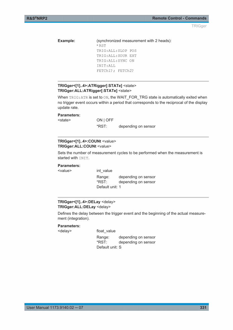
Remote Control - CommandsR&S®NRP2
331User Manual 1173.9140.02 ─ 07
Example: (synchronized measurement with 2 heads):*RSTTRIG:ALL:SLOP POSTRIG:ALL:SOUR EXTTRIG:ALL:SYNC ONINIT:ALLFETCh1?; FETCh2?
TRIGger<[1]..4>:ATRigger[:STATe] <state>TRIGger:ALL:ATRigger[:STATe] <state>
When TRIG:ATR is set to ON, the WAIT_FOR_TRG state is automatically exited whenno trigger event occurs within a period that corresponds to the reciprocal of the displayupdate rate.
Parameters:<state> ON | OFF
*RST: depending on sensor
TRIGger<[1]..4>:COUNt <value>TRIGger:ALL:COUNt <value>
Sets the number of measurement cycles to be performed when the measurement isstarted with INIT.
Parameters:<value> int_value
Range: depending on sensor*RST: depending on sensorDefault unit: 1
TRIGger<[1]..4>:DELay <delay>TRIGger:ALL:DELay <delay>
Defines the delay between the trigger event and the beginning of the actual measure-ment (integration).
Parameters:<delay> float_value
Range: depending on sensor*RST: depending on sensorDefault unit: S
TRIGger
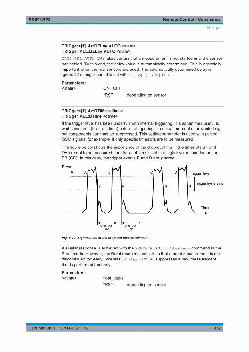
Remote Control - CommandsR&S®NRP2
332User Manual 1173.9140.02 ─ 07
TRIGger<[1]..4>:DELay:AUTO <state>TRIGger:ALL:DELay:AUTO <state>
TRIG:DEL:AUTO ON makes certain that a measurement is not started until the sensorhas settled. To this end, the delay value is automatically determined. This is especiallyimportant when thermal sensors are used. The automatically determined delay isignored if a longer period is set with TRIG<[1]..4>]:DEL.
Parameters:<state> ON | OFF
*RST: depending on sensor
TRIGger<[1]..4>:DTIMe <dtime>TRIGger:ALL:DTIMe <dtime>
If the trigger level has been underrun with internal triggering, it is sometimes useful towait some time (drop-out time) before retriggering. The measurement of unwanted sig-nal components can thus be suppressed. This setting parameter is used with pulsedGSM signals, for example, if only specific timeslots are to be measured.
The figure below shows the importance of the drop-out time. If the timeslots BF andDH are not to be measured, the drop-out time is set to a higher value than the periodEB (GD). In this case, the trigger events B and D are ignored.
Trigger level
Power
Time
Drop-OutTime
Trigger hysteresis
A B C D
E F G H
Drop-OutTime
Fig. 6-20: Significance of the drop-out time parameter
A similar response is achieved with the SENSe:BURSt:DTOLerance command in theBurst mode. However, the Burst mode makes certain that a burst measurement is notdiscontinued too early, whereas TRIGger:DTIMe suppresses a new measurementthat is performed too early.
Parameters:<dtime> float_value
*RST: depending on sensor
TRIGger
Remote Control - CommandsR&S®NRP2
333User Manual 1173.9140.02 ─ 07
TRIGger<[1]..4>:HOLDoff <holdoff>TRIGger:ALL:HOLDoff <holdoff>
Defines a period after a trigger event within which all further trigger events are ignored.
Parameters:<holdoff> float_value
Range: depending on sensor*RST: depending on sensorDefault unit: S
TRIGger<[1]..4>:HYSTeresis <value>TRIGger:ALL:HYSTeresis <value>
This command is used to specify how far the signal level has to drop below the triggerlevel before a new signal edge can be detected as a trigger event. Thus, this commandcan be used to eliminate the effects of noise in the signal on the edge detector of thetrigger system.
Unit: DB | PCT
Parameters:<value> float_value
Range: depending on sensor*RST: depending on sensorDefault unit: DB
TRIGger<[1]..4>[:IMMediate]TRIGger:ALL[:IMMediate]Performs triggering and makes sure that the sensor directly changes from theWAIT_FOR_TRG state to the MEASURING state irrespective of the selected triggersource (TRIG:SOUR). A trigger delay set with TRIG:DEL is ignored but not the auto-matic delay determined when TRIG:DEL:AUTO:ON is set. When the trigger source isHOLD, a measurement can only be started with TRIG.
Error messages:
-211 "Trigger ignored": The sensor is not in the WAIT_FOR_TRG state.
Usage: Event
TRIGger<[1]..4>:LEVel <level>TRIGger:ALL:LEVel <level>
Determines the power a trigger signal must exceed (TRIG:SLOP POS) or fall short of(TRIG:SLOP NEG) before a trigger event is detected. This setting is only used for thetrigger signal source (TRIG:SOUR INTernal).
Unit: DBM | W
TRIGger
Remote Control - CommandsR&S®NRP2
334User Manual 1173.9140.02 ─ 07
Parameters:<level> float_value
Range: depending on sensor*RST: depending on sensorDefault unit: DBM
TRIGger<[1]..4>:MASTer[:STATe] <state>
Sets the selected sensor in trigger master state. If the trigger master detects an(inter-nal) trigger event, it generates an external (hardware) trigger signal, which allows thesynchronous triggering of other sensors. The trigger master must be not be set toexternal triggering, however, all other sensors have too be set to external triggering(TRIG:SOUR EXT). The trigger signal generated by the trigger master is routed viathe connecting cable to the R&S NRP2 and from there distributed to the other sensorsand the trigger output. Only one sensor can be trigger master at a time.
See also TRIG:SYNC
Parameters:<state> ON | OFF
*RST: depending on sensor
TRIGger<[1]..4>:SLOPe <state>TRIGger:ALL:SLOPe <state>
This command determines whether the rising (POSitive) or the falling (NEGative)edge of the signal is used for triggering.
Parameters:<state> POSitive | NEGative
*RST: depending on sensor
TRIGger<[1]..4>:SOURce <state>TRIGger:ALL:SOURce <state>
Sets the trigger signal source for the WAIT_FOR_TRG state.
TRIGger
Remote Control - CommandsR&S®NRP2
335User Manual 1173.9140.02 ─ 07
Parameters:<state> BUS | EXTernal | HOLD | IMMediate | INTernal
BUSThe trigger event is initiated by TRIG:IMM or *TRG. In this case,the other trigger setting are meaningless.EXTernalTriggering is performed with an external signal applied to thetrigger connector. The TRIG:SLOP command determineswhether the rising or the falling edge of the signal is to be usedfor triggering. Waiting for a trigger event can be skipped byTRIG:IMM.
HOLDA measurement can only be triggered when the commandTRIG:IMM is executed.
IMMediateThe sensor does not remain in the WAIT_FOR_TRG state butimmediately changes to the MEASURING state.INTernalThe sensor determines the trigger time by means of the signal tobe measured. When this signal exceeds (TRIG:SLOP POS) orfall short of (TRIG:SLOP NEG) the power set by TRIG:LEV, themeasurement is started after the time set by TRIG:DEL. Similarto TRIG:SOUR EXT, waiting for a trigger event can also be skip-ped by TRIG:IMM.
*RST: depending on sensor
TRIGger<[1]..4>:SYNChronize[:STATe] <state>
If set to ON, the command blocks the external trigger bus as long as the sensor is not inWAIT_FOR_TRIGGER state. It is usually used in combination with commandTRIG:MAST and makes certain, that a new measurement will only be started after allsensors have completed their last measurement.
Parameters:<state> ON | OFF
*RST: depending on sensor
6.16 UNIT
Commands of the UNIT system
UNIT<[1]..8>:POWer...................................................................................................... 336UNIT<[1]..8>:POWer:RATio............................................................................................ 336
UNIT
Remote Control - CommandsR&S®NRP2
336User Manual 1173.9140.02 ─ 07
UNIT<[1]..8>:POWer <output_unit>
Selects the output unit for the measured power values.
This setting also determines the unit for the parameters of the following commands:● CALC:REL● CALC:LIM:UPP● CALC:LIM:LOW● DISP:MET:UPP● DISP:MET:LOW● OUTP:REC:LIM:LOW● OUTP:REC:LIM:UPPParameters:<output_unit> DBM | W | DBUV
*RST: DBM
UNIT<[1]..8>:POWer:RATio <output_unit>
Selects the output unit for the measured power ratio values.
This setting also determines the unit for the parameters of the following commands:● CALC:REL● CALC:LIM:UPP● CALC:LIM:LOW● DISP:MET:UPP● DISP:MET:LOW● OUTP:REC:LIM:LOW● OUTP:REC:LIM:UPPError messages:
If the compute function of the associated calculate block is :SWR, :RLOSs or :REFLection, then the unit cannot be changed and error message 26,"State not sup-ported", is output.
Parameters:<output_unit> DB | DPCT | O
*RST: DB
UNIT
MaintenanceR&S®NRP2
337User Manual 1173.9140.02 ─ 07
7 MaintenanceUnder normal operating conditions the R&S NRP2 does not require any regular main-tenance except for occasional cleaning of the front panel. Make sure that the air ventsare not obstructed.
Instrument damage caused by cleaning agentsCleaning agents contain substances that may damage the instrument. For example,cleaning agents that contain a solvent may damage the front panel labeling, plasticparts, or the display.Never use cleaning agents such as solvents (thinners, acetone, etc), acids, bases, orother substances.The outside of the instrument can be cleaned sufficiently using a soft, lint-free dustcloth.
7.1 Sensor test
The sensor selftest is described in chapter 4.7.6.1, "Internal sensor selftest",on page 162.
7.2 Instrument selftest
The R&S NRP2 carries out a selftest during booting. This selftest is described in chap-ter 1.8.2, "Startup", on page 18.
7.3 Cleaning the exterior
To clean the exterior, use a soft, lintfree cloth and an alcohol-free solvent, e.g. a com-mercially available dishwashing liquid.
7.4 Storage
Please see data sheet for storage temperature range of the R&S NRP2.
Sensor test

MaintenanceR&S®NRP2
338User Manual 1173.9140.02 ─ 07
Storage
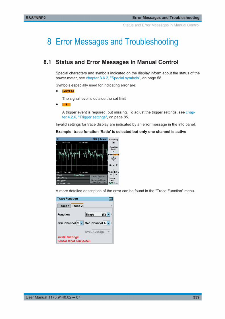
Error Messages and TroubleshootingR&S®NRP2
339User Manual 1173.9140.02 ─ 07
8 Error Messages and Troubleshooting
8.1 Status and Error Messages in Manual Control
Special characters and symbols indicated on the display inform about the status of thepower meter, see chapter 3.6.2, "Special symbols", on page 58.
Symbols especially used for indicating error are:●
The signal level is outside the set limit●
A trigger event is required, but missing. To adjust the trigger settings, see chap-ter 4.2.6, "Trigger settings", on page 85.
Invalid settings for trace display are indicated by an error message in the info panel.
Example: trace function 'Ratio' is selected but only one channel is active
A more detailed description of the error can be found in the "Trace Function" menu.
Status and Error Messages in Manual Control
Error Messages and TroubleshootingR&S®NRP2
340User Manual 1173.9140.02 ─ 07
8.2 SCPI-Specific Error Messages
The list below contains error messages that may occur in the instrument. Negativeerror numbers are defined in the SCPI standard, positive error numbers identify device-specific errors.
The left column of the following table gives the error code. In the right column, the textof the error message displayed or entered in the error/event queue is printed in bold.An additional explanation is given below this text.
8.2.1 No error
Error code "Error text returned upon queue query"
Explanations
0 "No error"
This message is displayed if the error queue is empty.
8.2.2 Command Error
Command errors; causes bit 5 in the ESR to be set.
Error code
Error text returned upon queue query
Explanations
-100 "Command error"
Command faulty or invalid.
-101 "Invalid character"
The command contains a character which is invalid for that type.
-102 "Syntax error"
The command is invalid.
-103 "Invalid separator"
Command contains an illegal character where a separator is expected.
-104 "Data type error"
Command contains an invalid data element.
-108 "Parameter not allowed"
The command contains too many parameters.
-109 "Missing parameter"
The command contains fewer parameters than required.
-111 "Header separator error"
The header contains an illegal delimiter.
-112 "Program mnemonic too long"
The header contains more than 12 characters.
SCPI-Specific Error Messages
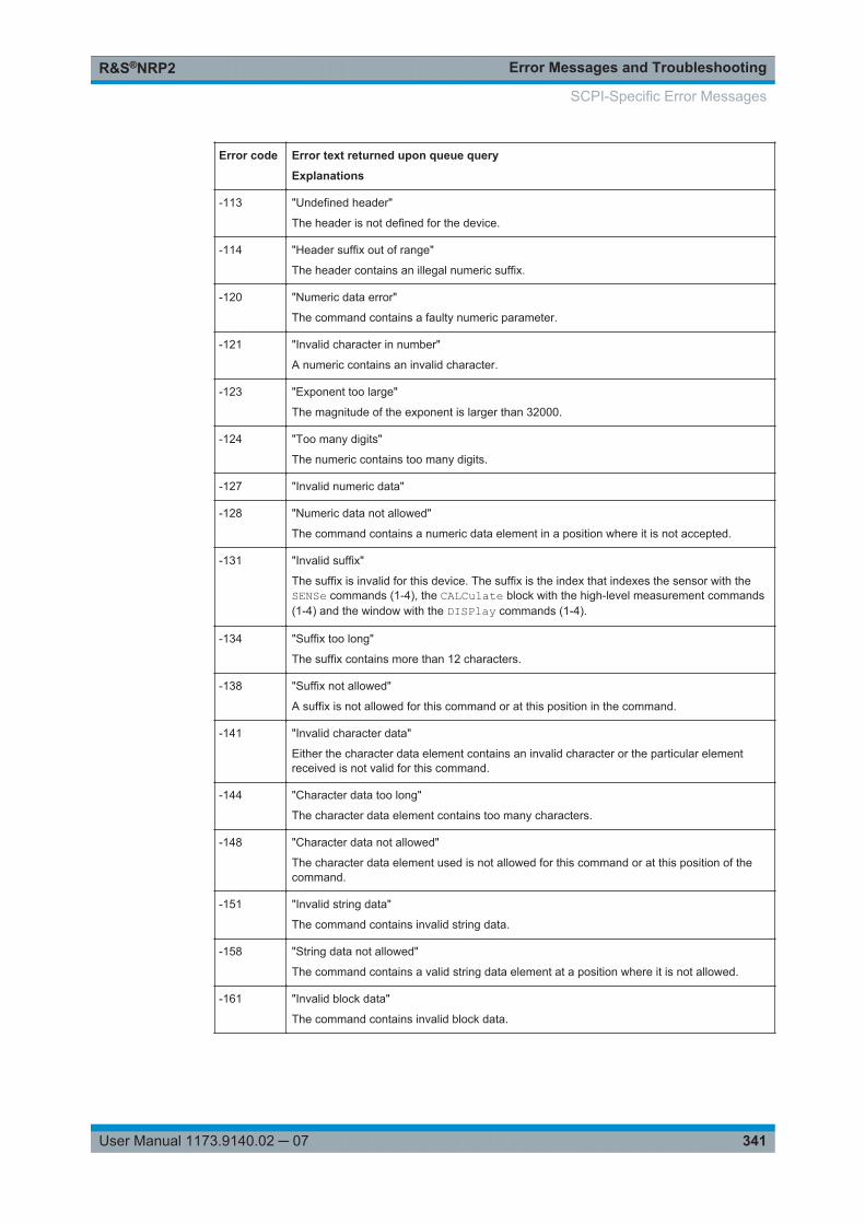
Error Messages and TroubleshootingR&S®NRP2
341User Manual 1173.9140.02 ─ 07
Error code
Error text returned upon queue query
Explanations
-113 "Undefined header"
The header is not defined for the device.
-114 "Header suffix out of range"
The header contains an illegal numeric suffix.
-120 "Numeric data error"
The command contains a faulty numeric parameter.
-121 "Invalid character in number"
A numeric contains an invalid character.
-123 "Exponent too large"
The magnitude of the exponent is larger than 32000.
-124 "Too many digits"
The numeric contains too many digits.
-127 "Invalid numeric data"
-128 "Numeric data not allowed"
The command contains a numeric data element in a position where it is not accepted.
-131 "Invalid suffix"
The suffix is invalid for this device. The suffix is the index that indexes the sensor with theSENSe commands (1-4), the CALCulate block with the high-level measurement commands(1-4) and the window with the DISPlay commands (1-4).
-134 "Suffix too long"
The suffix contains more than 12 characters.
-138 "Suffix not allowed"
A suffix is not allowed for this command or at this position in the command.
-141 "Invalid character data"
Either the character data element contains an invalid character or the particular elementreceived is not valid for this command.
-144 "Character data too long"
The character data element contains too many characters.
-148 "Character data not allowed"
The character data element used is not allowed for this command or at this position of thecommand.
-151 "Invalid string data"
The command contains invalid string data.
-158 "String data not allowed"
The command contains a valid string data element at a position where it is not allowed.
-161 "Invalid block data"
The command contains invalid block data.
SCPI-Specific Error Messages
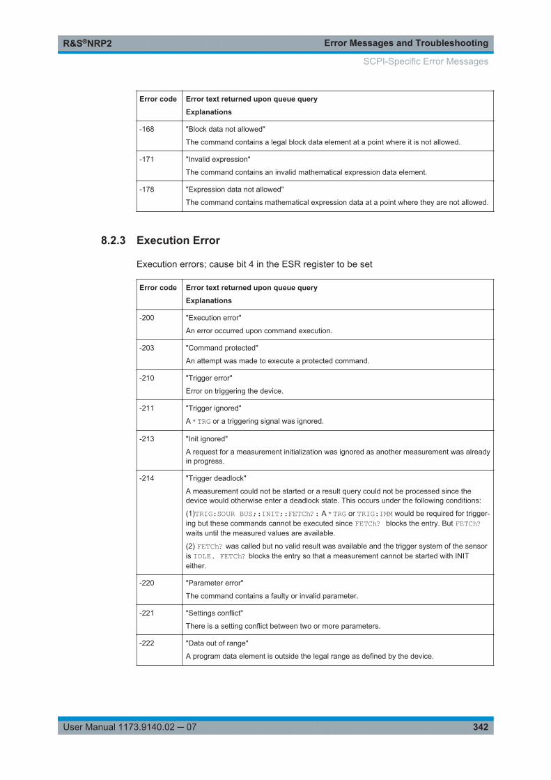
Error Messages and TroubleshootingR&S®NRP2
342User Manual 1173.9140.02 ─ 07
Error code
Error text returned upon queue query
Explanations
-168 "Block data not allowed"
The command contains a legal block data element at a point where it is not allowed.
-171 "Invalid expression"
The command contains an invalid mathematical expression data element.
-178 "Expression data not allowed"
The command contains mathematical expression data at a point where they are not allowed.
8.2.3 Execution Error
Execution errors; cause bit 4 in the ESR register to be set
Error code
Error text returned upon queue query
Explanations
-200 "Execution error"
An error occurred upon command execution.
-203 "Command protected"
An attempt was made to execute a protected command.
-210 "Trigger error"
Error on triggering the device.
-211 "Trigger ignored"
A *TRG or a triggering signal was ignored.
-213 "Init ignored"
A request for a measurement initialization was ignored as another measurement was alreadyin progress.
-214 "Trigger deadlock"
A measurement could not be started or a result query could not be processed since thedevice would otherwise enter a deadlock state. This occurs under the following conditions:
(1)TRIG:SOUR BUS;:INIT;:FETCh?: A *TRG or TRIG:IMM would be required for trigger-ing but these commands cannot be executed since FETCh? blocks the entry. But FETCh?waits until the measured values are available.
(2) FETCh? was called but no valid result was available and the trigger system of the sensoris IDLE. FETCh? blocks the entry so that a measurement cannot be started with INITeither.
-220 "Parameter error"
The command contains a faulty or invalid parameter.
-221 "Settings conflict"
There is a setting conflict between two or more parameters.
-222 "Data out of range"
A program data element is outside the legal range as defined by the device.
SCPI-Specific Error Messages
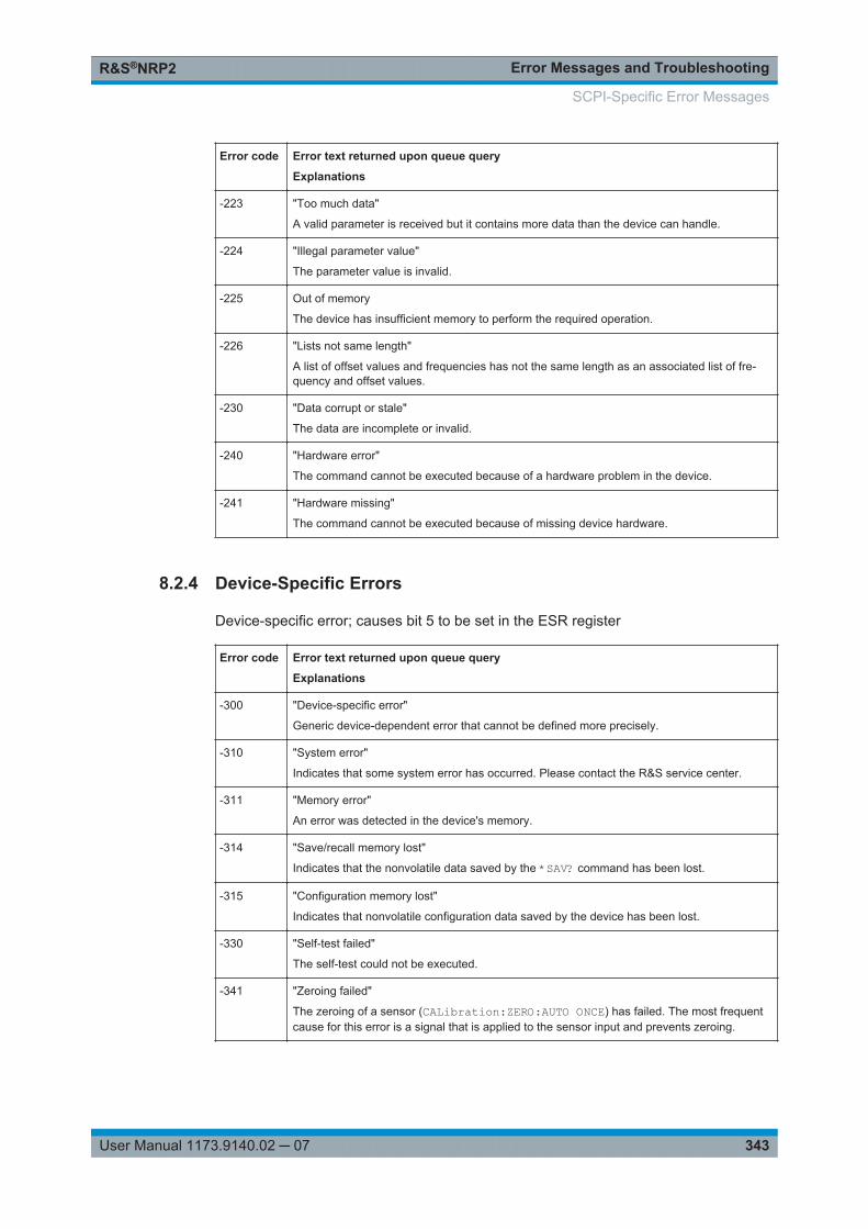
Error Messages and TroubleshootingR&S®NRP2
343User Manual 1173.9140.02 ─ 07
Error code
Error text returned upon queue query
Explanations
-223 "Too much data"
A valid parameter is received but it contains more data than the device can handle.
-224 "Illegal parameter value"
The parameter value is invalid.
-225 Out of memory
The device has insufficient memory to perform the required operation.
-226 "Lists not same length"
A list of offset values and frequencies has not the same length as an associated list of fre-quency and offset values.
-230 "Data corrupt or stale"
The data are incomplete or invalid.
-240 "Hardware error"
The command cannot be executed because of a hardware problem in the device.
-241 "Hardware missing"
The command cannot be executed because of missing device hardware.
8.2.4 Device-Specific Errors
Device-specific error; causes bit 5 to be set in the ESR register
Error code
Error text returned upon queue query
Explanations
-300 "Device-specific error"
Generic device-dependent error that cannot be defined more precisely.
-310 "System error"
Indicates that some system error has occurred. Please contact the R&S service center.
-311 "Memory error"
An error was detected in the device's memory.
-314 "Save/recall memory lost"
Indicates that the nonvolatile data saved by the *SAV? command has been lost.
-315 "Configuration memory lost"
Indicates that nonvolatile configuration data saved by the device has been lost.
-330 "Self-test failed"
The self-test could not be executed.
-341 "Zeroing failed"
The zeroing of a sensor (CALibration:ZERO:AUTO ONCE) has failed. The most frequentcause for this error is a signal that is applied to the sensor input and prevents zeroing.
SCPI-Specific Error Messages

Error Messages and TroubleshootingR&S®NRP2
344User Manual 1173.9140.02 ─ 07
Error code
Error text returned upon queue query
Explanations
-350 "Queue overflow"
This code is entered into the queue in lieu of the code that caused the error. It indicates thatan error occurred but was not recorded. Five entries are accepted in the queue.
-363 "Input buffer overrun"
More commands were sent to the device than can be simultaneously executed or stored.
8.2.5 Query Errors
Query errors; cause bit 2 in the ESR register to be set
Error code
Error text returned upon queue query
Explanations
-400 "Query error"
Generic query error that cannot be defined more precisely.
-410 "Query INTERRUPTED"
The query was interrupted.
Example:
The query is followed by new data before the response was completely sent.
-420 "Query UNTERMINATED"
An incomplete query was received.
-430 "Query DEADLOCKED"
The query cannot be processed.
-440 "Query UNTERMINATED after indefinite response"
A query is received in the same program message after a query requesting an indefiniteresponse.
8.2.6 Device-Dependent Errors
Device-dependent error; causes bit 5 to be set in the ESR register
Error code
Error text returned upon queue query
Explanations
1 "Device-dependent error"
This error message is sent when the device cannot detect a more specific error.
2 "IEEE 1174 error (unknown emulation code)"
An invalid IEEE-1174 emulation mode was selected for the Ethernet link.
22 IEEE1174 mode 488.1 not allowed
Setting the IEEE 1174.1 mode is not permissible.
SCPI-Specific Error Messages
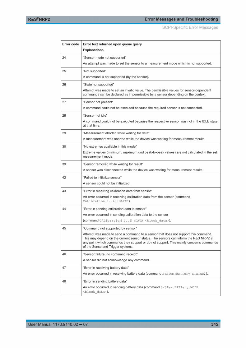
Error Messages and TroubleshootingR&S®NRP2
345User Manual 1173.9140.02 ─ 07
Error code
Error text returned upon queue query
Explanations
24 "Sensor mode not supported"
An attempt was made to set the sensor to a measurement mode which is not supported.
25 "Not supported"
A command is not supported (by the sensor).
26 "State not supported"
Attempt was made to set an invalid value. The permissible values for sensor-dependentcommands can be declared as impermissible by a sensor depending on the context.
27 "Sensor not present"
A command could not be executed because the required sensor is not connected.
28 "Sensor not idle"
A command could not be executed because the respective sensor was not in the IDLE stateat that time.
29 "Measurement aborted while waiting for data"
A measurement was aborted while the device was waiting for measurement results.
30 "No extremes available in this mode"
Extreme values (minimum, maximum und peak-to-peak values) are not calculated in the setmeasurement mode.
39 "Sensor removed while waiting for result"
A sensor was disconnected while the device was waiting for measurement results.
42 "Failed to initialize sensor"
A sensor could not be initialized.
43 "Error in receiving calibration data from sensor"
An error occurred in receiving calibration data from the sensor (commandCALibration[1..4]:DATA?).
44 "Error in sending calibration data to sensor"
An error occurred in sending calibration data to the sensor
(command CALibration[1..4]:DATA <block_data>).
45 "Command not supported by sensor"
Attempt was made to send a command to a sensor that does not support this command.This may depend on the current sensor status. The sensors can inform the R&S NRP2 atany point which commands they support or do not support. This mainly concerns commandsof the Sense and Trigger systems.
46 "Sensor failure: no command receipt"
A sensor did not acknowledge any command.
47 "Error in receiving battery data"
An error occurred in receiving battery data (command SYSTem:BATTery:STATus?).
48 "Error in sending battery data"
An error occurred in sending battery data (command SYSTem:BATTery:MODE<block_data>).
SCPI-Specific Error Messages
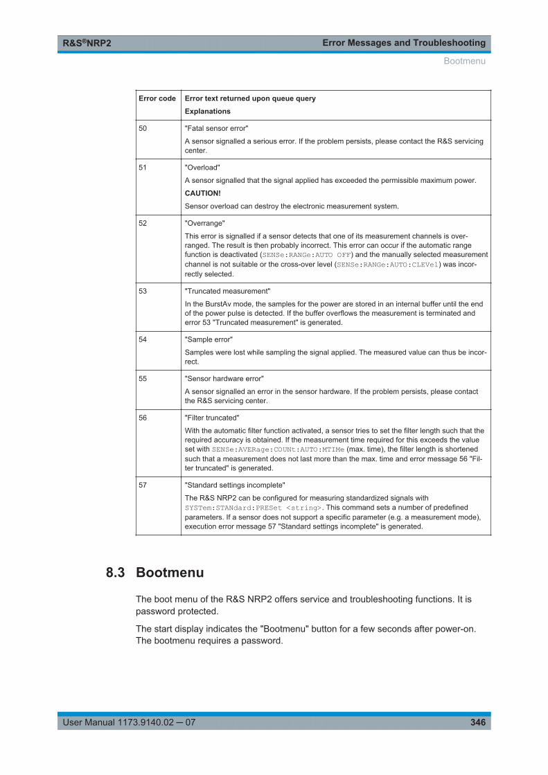
Error Messages and TroubleshootingR&S®NRP2
346User Manual 1173.9140.02 ─ 07
Error code
Error text returned upon queue query
Explanations
50 "Fatal sensor error"
A sensor signalled a serious error. If the problem persists, please contact the R&S servicingcenter.
51 "Overload"
A sensor signalled that the signal applied has exceeded the permissible maximum power.
CAUTION!
Sensor overload can destroy the electronic measurement system.
52 "Overrange"
This error is signalled if a sensor detects that one of its measurement channels is over-ranged. The result is then probably incorrect. This error can occur if the automatic rangefunction is deactivated (SENSe:RANGe:AUTO OFF) and the manually selected measurementchannel is not suitable or the cross-over level (SENSe:RANGe:AUTO:CLEVel) was incor-rectly selected.
53 "Truncated measurement"
In the BurstAv mode, the samples for the power are stored in an internal buffer until the endof the power pulse is detected. If the buffer overflows the measurement is terminated anderror 53 "Truncated measurement" is generated.
54 "Sample error"
Samples were lost while sampling the signal applied. The measured value can thus be incor-rect.
55 "Sensor hardware error"
A sensor signalled an error in the sensor hardware. If the problem persists, please contactthe R&S servicing center.
56 "Filter truncated"
With the automatic filter function activated, a sensor tries to set the filter length such that therequired accuracy is obtained. If the measurement time required for this exceeds the valueset with SENSe:AVERage:COUNt:AUTO:MTIMe (max. time), the filter length is shortenedsuch that a measurement does not last more than the max. time and error message 56 "Fil-ter truncated" is generated.
57 "Standard settings incomplete"
The R&S NRP2 can be configured for measuring standardized signals withSYSTem:STANdard:PRESet <string>. This command sets a number of predefinedparameters. If a sensor does not support a specific parameter (e.g. a measurement mode),execution error message 57 "Standard settings incomplete" is generated.
8.3 Bootmenu
The boot menu of the R&S NRP2 offers service and troubleshooting functions. It ispassword protected.
The start display indicates the "Bootmenu" button for a few seconds after power-on.The bootmenu requires a password.
Bootmenu
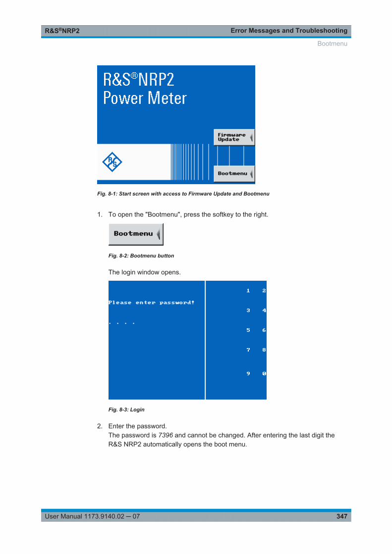
Error Messages and TroubleshootingR&S®NRP2
347User Manual 1173.9140.02 ─ 07
Fig. 8-1: Start screen with access to Firmware Update and Bootmenu
1. To open the "Bootmenu", press the softkey to the right.
Fig. 8-2: Bootmenu button
The login window opens.
Fig. 8-3: Login
2. Enter the password.The password is 7396 and cannot be changed. After entering the last digit theR&S NRP2 automatically opens the boot menu.
Bootmenu
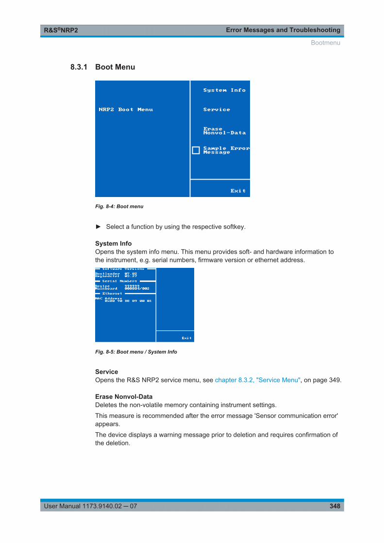
Error Messages and TroubleshootingR&S®NRP2
348User Manual 1173.9140.02 ─ 07
8.3.1 Boot Menu
Fig. 8-4: Boot menu
► Select a function by using the respective softkey.
System InfoOpens the system info menu. This menu provides soft- and hardware information tothe instrument, e.g. serial numbers, firmware version or ethernet address.
Fig. 8-5: Boot menu / System Info
ServiceOpens the R&S NRP2 service menu, see chapter 8.3.2, "Service Menu", on page 349.
Erase Nonvol-DataDeletes the non-volatile memory containing instrument settings.
This measure is recommended after the error message 'Sensor communication error'appears.
The device displays a warning message prior to deletion and requires confirmation ofthe deletion.
Bootmenu
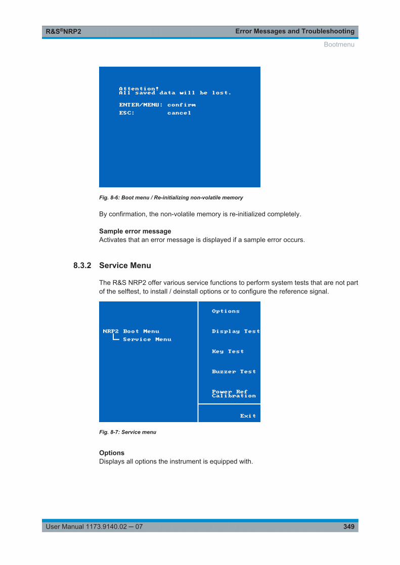
Error Messages and TroubleshootingR&S®NRP2
349User Manual 1173.9140.02 ─ 07
Fig. 8-6: Boot menu / Re-initializing non-volatile memory
By confirmation, the non-volatile memory is re-initialized completely.
Sample error messageActivates that an error message is displayed if a sample error occurs.
8.3.2 Service Menu
The R&S NRP2 offer various service functions to perform system tests that are not partof the selftest, to install / deinstall options or to configure the reference signal.
Fig. 8-7: Service menu
OptionsDisplays all options the instrument is equipped with.
Bootmenu
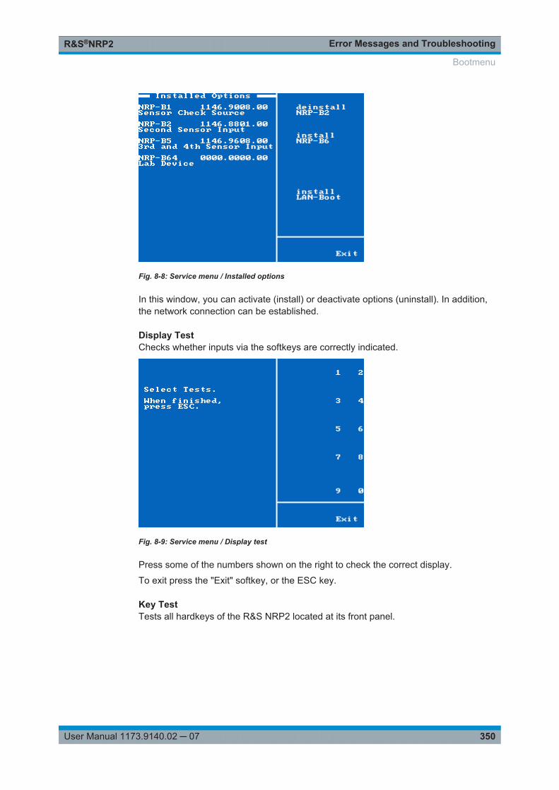
Error Messages and TroubleshootingR&S®NRP2
350User Manual 1173.9140.02 ─ 07
Fig. 8-8: Service menu / Installed options
In this window, you can activate (install) or deactivate options (uninstall). In addition,the network connection can be established.
Display TestChecks whether inputs via the softkeys are correctly indicated.
Fig. 8-9: Service menu / Display test
Press some of the numbers shown on the right to check the correct display.
To exit press the "Exit" softkey, or the ESC key.
Key TestTests all hardkeys of the R&S NRP2 located at its front panel.
Bootmenu
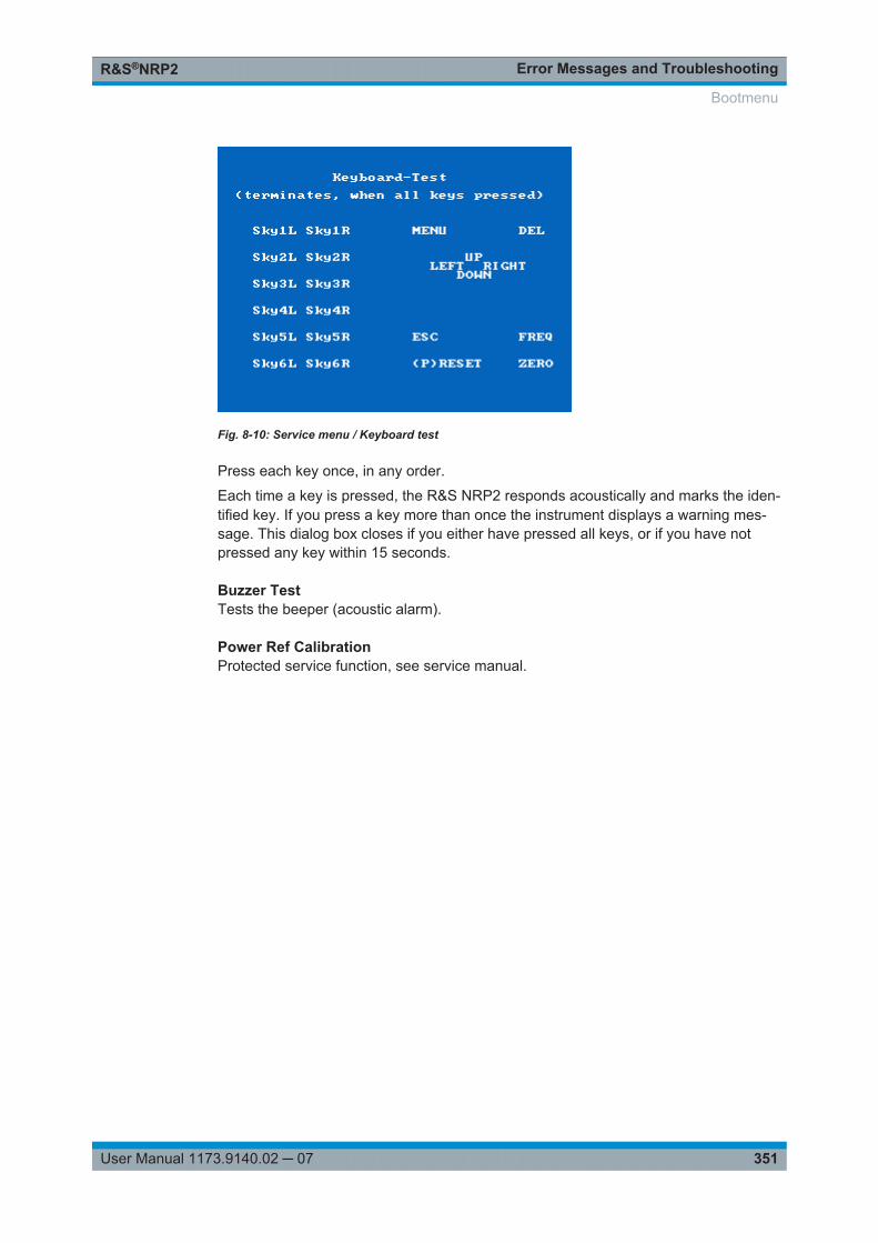
Error Messages and TroubleshootingR&S®NRP2
351User Manual 1173.9140.02 ─ 07
Fig. 8-10: Service menu / Keyboard test
Press each key once, in any order.
Each time a key is pressed, the R&S NRP2 responds acoustically and marks the iden-tified key. If you press a key more than once the instrument displays a warning mes-sage. This dialog box closes if you either have pressed all keys, or if you have notpressed any key within 15 seconds.
Buzzer TestTests the beeper (acoustic alarm).
Power Ref CalibrationProtected service function, see service manual.
Bootmenu

Error Messages and TroubleshootingR&S®NRP2
352User Manual 1173.9140.02 ─ 07
Bootmenu
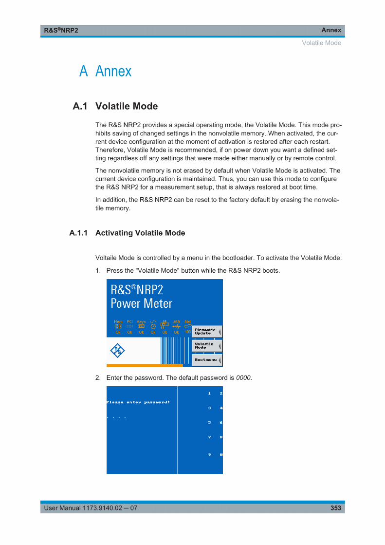
AnnexR&S®NRP2
353User Manual 1173.9140.02 ─ 07
A Annex
A.1 Volatile Mode
The R&S NRP2 provides a special operating mode, the Volatile Mode. This mode pro-hibits saving of changed settings in the nonvolatile memory. When activated, the cur-rent device configuration at the moment of activation is restored after each restart.Therefore, Volatile Mode is recommended, if on power down you want a defined set-ting regardless off any settings that were made either manually or by remote control.
The nonvolatile memory is not erased by default when Volatile Mode is activated. Thecurrent device configuration is maintained. Thus, you can use this mode to configurethe R&S NRP2 for a measurement setup, that is always restored at boot time.
In addition, the R&S NRP2 can be reset to the factory default by erasing the nonvola-tile memory.
A.1.1 Activating Volatile Mode
Voltaile Mode is controlled by a menu in the bootloader. To activate the Volatile Mode:
1. Press the "Volatile Mode" button while the R&S NRP2 boots.
2. Enter the password. The default password is 0000.
Volatile Mode
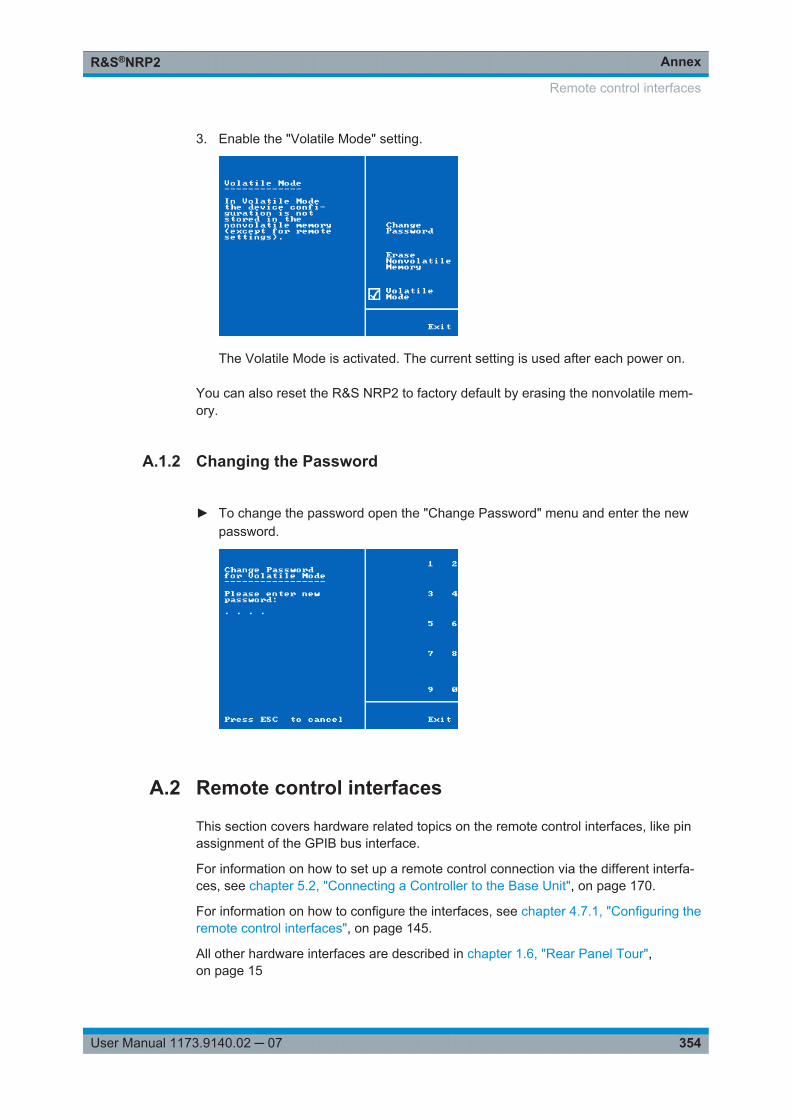
AnnexR&S®NRP2
354User Manual 1173.9140.02 ─ 07
3. Enable the "Volatile Mode" setting.
The Volatile Mode is activated. The current setting is used after each power on.
You can also reset the R&S NRP2 to factory default by erasing the nonvolatile mem-ory.
A.1.2 Changing the Password
► To change the password open the "Change Password" menu and enter the newpassword.
A.2 Remote control interfaces
This section covers hardware related topics on the remote control interfaces, like pinassignment of the GPIB bus interface.
For information on how to set up a remote control connection via the different interfa-ces, see chapter 5.2, "Connecting a Controller to the Base Unit", on page 170.
For information on how to configure the interfaces, see chapter 4.7.1, "Configuring theremote control interfaces", on page 145.
All other hardware interfaces are described in chapter 1.6, "Rear Panel Tour",on page 15
Remote control interfaces
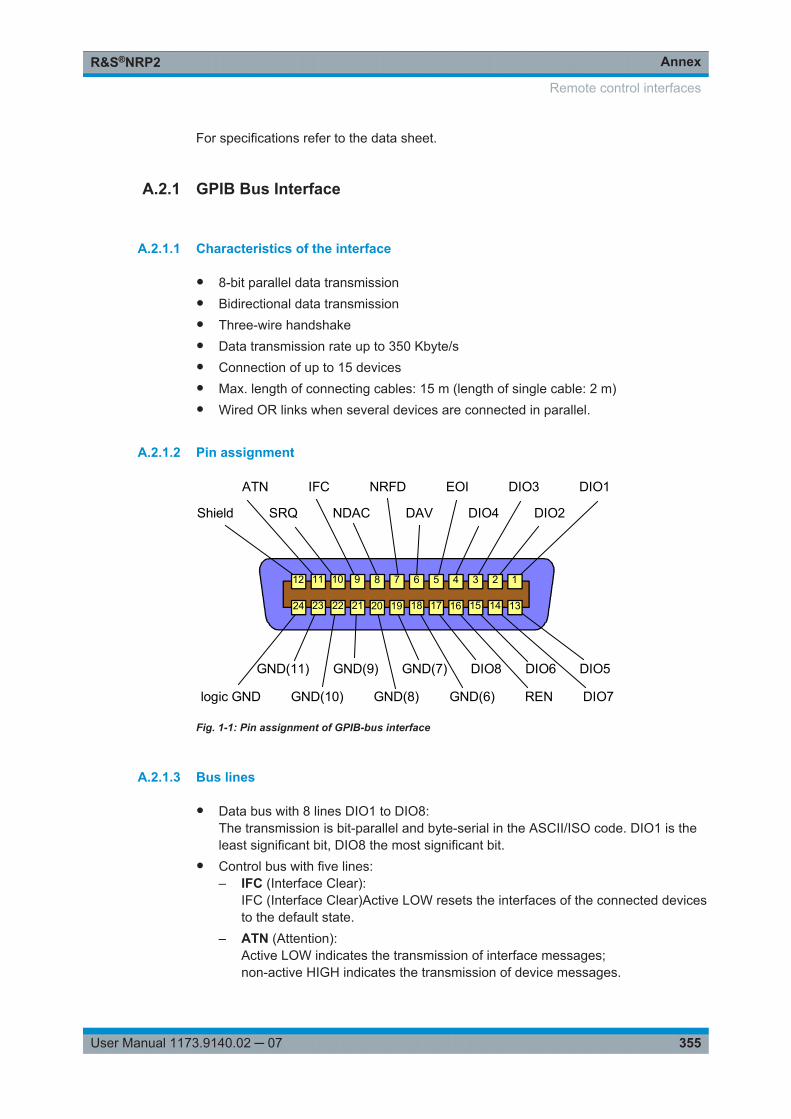
AnnexR&S®NRP2
355User Manual 1173.9140.02 ─ 07
For specifications refer to the data sheet.
A.2.1 GPIB Bus Interface
A.2.1.1 Characteristics of the interface
● 8-bit parallel data transmission● Bidirectional data transmission● Three-wire handshake● Data transmission rate up to 350 Kbyte/s● Connection of up to 15 devices● Max. length of connecting cables: 15 m (length of single cable: 2 m)● Wired OR links when several devices are connected in parallel.
A.2.1.2 Pin assignment
DIO1
DIO2
DIO3
DIO4
EOI
DAV
NRFD
NDAC
IFC
SRQ
ATN
Shield
DIO7RENGND(6)logic GND GND(10) GND(8)
DIO5DIO6DIO8GND(11) GND(9) GND(7)
24 1314151617181920212223
112 11 10 9 8 7 6 5 4 3 2
Fig. 1-1: Pin assignment of GPIB-bus interface
A.2.1.3 Bus lines
● Data bus with 8 lines DIO1 to DIO8:The transmission is bit-parallel and byte-serial in the ASCII/ISO code. DIO1 is theleast significant bit, DIO8 the most significant bit.
● Control bus with five lines:– IFC (Interface Clear):
IFC (Interface Clear)Active LOW resets the interfaces of the connected devicesto the default state.
– ATN (Attention):Active LOW indicates the transmission of interface messages;non-active HIGH indicates the transmission of device messages.
Remote control interfaces
AnnexR&S®NRP2
356User Manual 1173.9140.02 ─ 07
– SRQ (Service Request):Active LOW enables a device to send a service request to the controller.
– REN (Remote Enable):Active LOW permits switchover to remote control.
– EOI (End or Identify):Has two functions in connection with ATN:ATN = HIGH: active LOW marks the end of data transmissionATN = LOW: active LOW triggers a parallel poll.
● Handshake bus with three lines:– DAV (Data Valid):
Active LOW signals a valid data byte on the data bus.– NRFD (Not Ready For Data):
Active LOW signals that one of the connected devices is not ready for datatransfer.
– NDAC (Not Data Accepted):Active LOW until the connected device has accepted the data on the bus.
A.2.1.4 GPIB bus interface
Instruments which can be controlled via GPIB bus can be equipped with different inter-face functions. The interface function for the R&S NRP2 are listed in the followingtable.
Table 1-1: GPIB bus interface functions
Controlcharacter
Interface function
SH1 Source handshake
AH1 Acceptor handshake
L3 Listener function, Listen-Only mode, unaddressed for MSA and TPAS, recognizes END andEOS.
LE3 Extended Listener function, Listen-Only mode, unaddressed for MSA and TPAS, recogni-zes END and EOS.
T5 Talker function, capability to respond to serial poll, Talk-Only mode, unaddressed on MLA,sends END or EOS.
TE5 Extended talker function, capability to respond to serial poll, Talk-Only mode, unaddressedfor MLA and LPAS, sends END or EOS.
SR1 Service request function
PP1 Remote parallel-poll function
PP2 Local parallel-poll function
RL1 Remote/local switchover function
DC1 Device clear
E2 3-state driver (open-collector driver during parallel poll)
Remote control interfaces
AnnexR&S®NRP2
357User Manual 1173.9140.02 ─ 07
Controlcharacter
Interface function
DT1 Device trigger
C0 No controller capabilities
A.2.1.5 Interface messages
Interface messages are transmitted to the device on data lines, where the ATN is set toactive LOW. They are used for communication between the controller and theR&S NRP2.
Common commands
Common commands are in the code range 0x10 to 0x1F. They affect all devices on thebus without any addressing being required.
Table 1-2: Common commands
Command Effect on device
DCL (Device Clear) Aborts all commands and messages in progress. The TRIGger sys-tem goes to the "IDLE" state, input and output queues are cleared,and the parser is reset and waits for the beginning of a new com-mand. When INITiate:CONT ON is set, a new measurement isstarted. This command makes the device ready to receive com-mands.
IFC (Interface Clear) Resets the interfaces to their initial condition.
LLO (Local Lockout) Manual switchover to LOCAL is disabled.
Local LockOut deactivates the front-panel keypad with the exceptionof the power key . In the LLO state, it is possible to return to the"LOCAL" mode only by remote control (GTL command) or switchingthe R&S NRP2 off and on again.
SPE (Serial Poll Enable) Ready for serial poll.
SPD (Serial Poll Disable) End of serial poll.
PPU (Parallel Poll Unconfigure) End of parallel poll query status.
Addressed commands
Addressed commands are in the code range 0x00 to 0x0F hex. They only affect devi-ces addressed as a listener.
Table 1-3: Addressed commands
Command Effect on device
SDC (Selected DeviceClear) Interrupts processing of received commands and sets the command pro-cessing software to a defined initial state. This command does notchange the device setting.
GTL (Go to Local) Change to local mode (manual control).
PPC (Parallel Poll Configure) Configures device for parallel poll.
Remote control interfaces
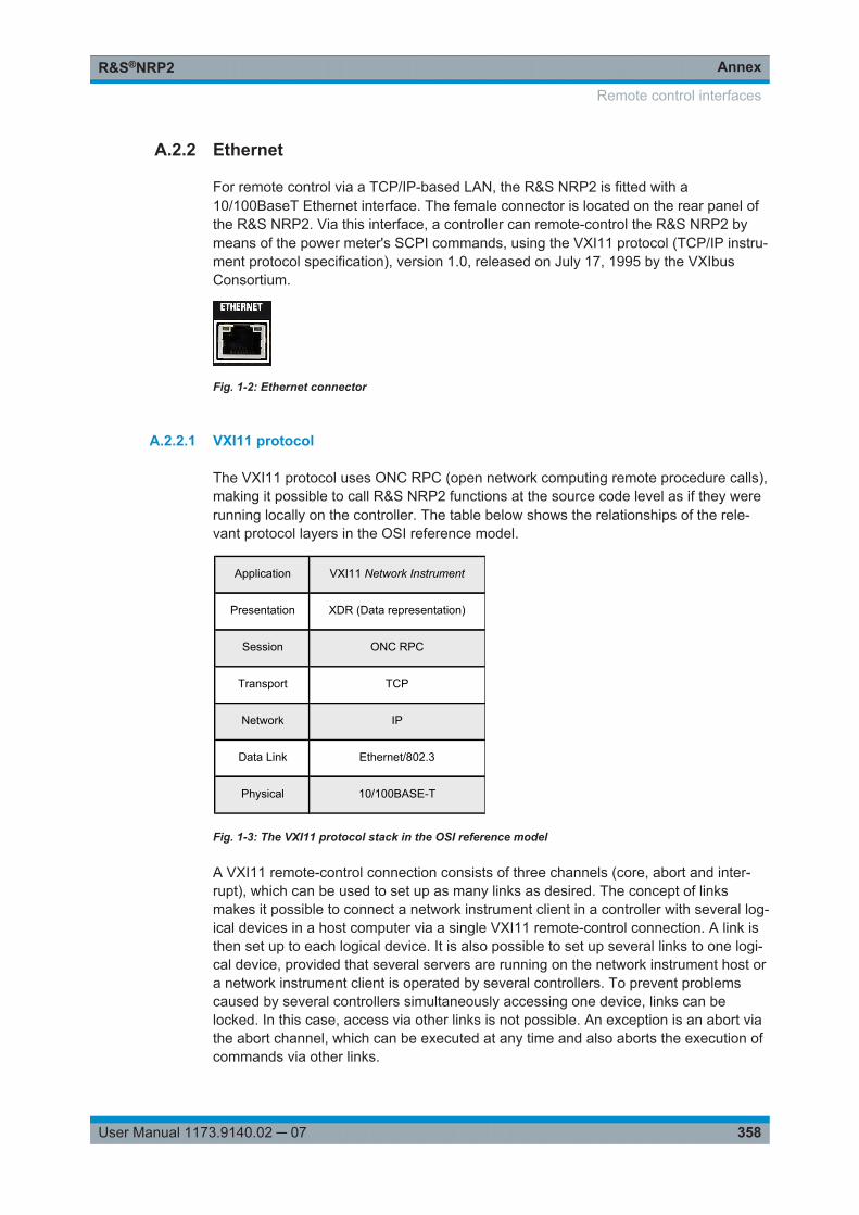
AnnexR&S®NRP2
358User Manual 1173.9140.02 ─ 07
A.2.2 Ethernet
For remote control via a TCP/IP-based LAN, the R&S NRP2 is fitted with a10/100BaseT Ethernet interface. The female connector is located on the rear panel ofthe R&S NRP2. Via this interface, a controller can remote-control the R&S NRP2 bymeans of the power meter's SCPI commands, using the VXI11 protocol (TCP/IP instru-ment protocol specification), version 1.0, released on July 17, 1995 by the VXIbusConsortium.
Fig. 1-2: Ethernet connector
A.2.2.1 VXI11 protocol
The VXI11 protocol uses ONC RPC (open network computing remote procedure calls),making it possible to call R&S NRP2 functions at the source code level as if they wererunning locally on the controller. The table below shows the relationships of the rele-vant protocol layers in the OSI reference model.
Application VXI11 Network Instrument
Presentation XDR (Data representation)
Session ONC RPC
Transport TCP
Network IP
Data Link Ethernet/802.3
Physical 10/100BASE-T
Fig. 1-3: The VXI11 protocol stack in the OSI reference model
A VXI11 remote-control connection consists of three channels (core, abort and inter-rupt), which can be used to set up as many links as desired. The concept of linksmakes it possible to connect a network instrument client in a controller with several log-ical devices in a host computer via a single VXI11 remote-control connection. A link isthen set up to each logical device. It is also possible to set up several links to one logi-cal device, provided that several servers are running on the network instrument host ora network instrument client is operated by several controllers. To prevent problemscaused by several controllers simultaneously accessing one device, links can belocked. In this case, access via other links is not possible. An exception is an abort viathe abort channel, which can be executed at any time and also aborts the execution ofcommands via other links.
Remote control interfaces
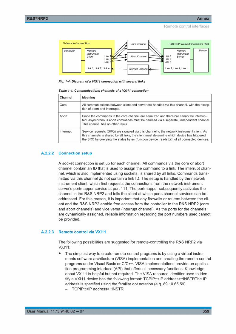
AnnexR&S®NRP2
359User Manual 1173.9140.02 ─ 07
Core Channel
Abort Channel
Interrupt Channel
Link 1Link 2Link n
Link 1, Link 2, Link n
NetworkInstrumentClient
Controller
Network Instrument Host
Link 1Link 2Link n
Link 1, Link 2, Link n
NetworkInstrumentServer
R&S NRP: Network Instrument Host
Device
Fig. 1-4: Diagram of a VXI11 connection with several links
Table 1-4: Communications channels of a VXI11 connection
Channel Meaning
Core All communications between client and server are handled via this channel, with the excep-tion of abort and interrupts.
Abort Since the commands in the core channel are serialized and therefore cannot be interrup-ted, asynchronous abort commands must be handled via a separate, independent channel.This channel has no other tasks.
Interrupt Service requests (SRQ) are signaled via this channel to the network instrument client. Asthis channels is shared by all links, the client must determine which device has triggeredthe SRQ by querying the status bytes (function device_readstb()) of all connected devices.
A.2.2.2 Connection setup
A socket connection is set up for each channel. All commands via the core or abortchannel contain an ID that is used to assign the command to a link. The interrupt chan-nel, which is also implemented using sockets, is shared by all links. Commands trans-mitted via this channel do not contain a link ID. The setup is handled by the networkinstrument client, which first requests the connections from the network instrumentserver's portmapper service at port 111. The portmapper subsequently activates thechannel in the R&S NRP2 and tells the client at which ports channel services can beaddressed. For this reason, it is important that any firewalls or routers between the cli-ent and the R&S NRP2 enable free access from the controller to the R&S NRP2 (coreand abort channels) and vice versa (interrupt channel). As the ports for the channelsare dynamically assigned, reliable information regarding the port numbers used cannotbe provided.
A.2.2.3 Remote control via VXI11
The following possibilities are suggested for remote-controlling the R&S NRP2 viaVXI11:● The simplest way to create remote-control programs is by using a virtual instru-
ments software architecture (VISA) implementation and creating the remote-controlprograms under Visual Basic or C/C++. VISA implementations provide an applica-tion programming interface (API) that offers all necessary functions. Knowledgeabout VXI11 is helpful but not required. The VISA resource identifier used to iden-tify a VXI11 device has the following format: TCPIP::<IP address>::INSTRThe IPaddress is specified using the familiar dot notation (e.g. 89.10.65.59).– TCPIP::<IP address>::INSTR
Remote control interfaces
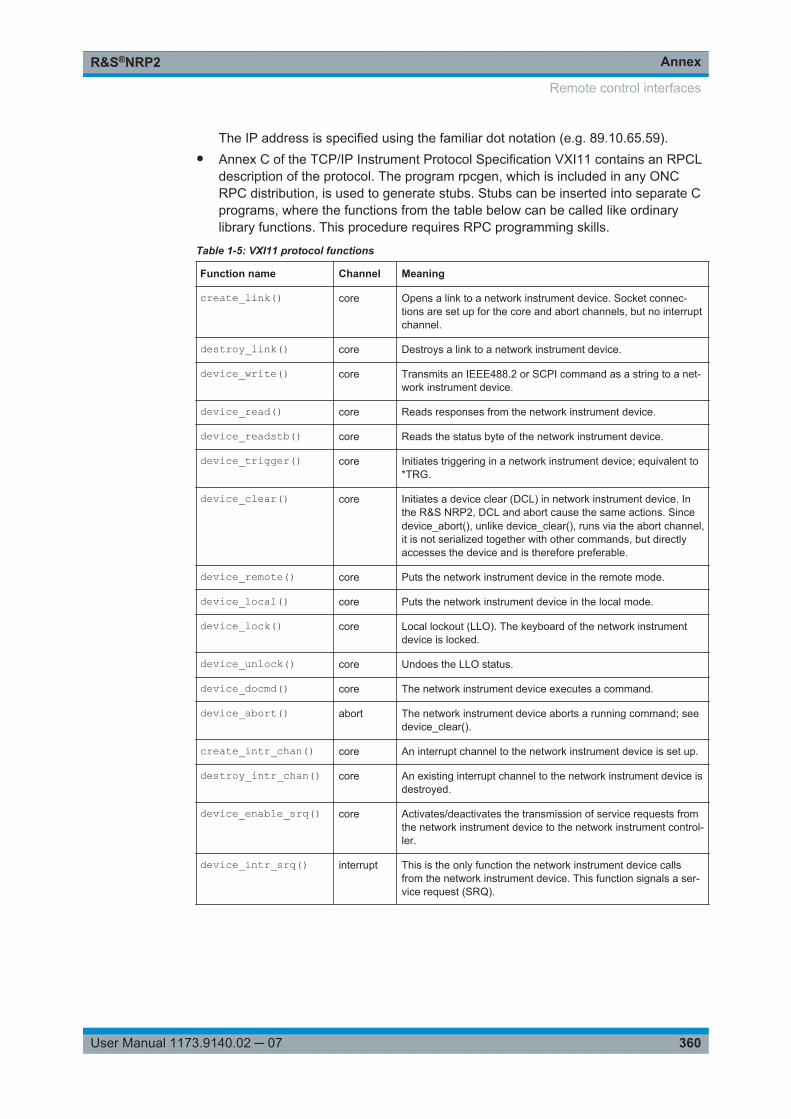
AnnexR&S®NRP2
360User Manual 1173.9140.02 ─ 07
The IP address is specified using the familiar dot notation (e.g. 89.10.65.59).● Annex C of the TCP/IP Instrument Protocol Specification VXI11 contains an RPCL
description of the protocol. The program rpcgen, which is included in any ONCRPC distribution, is used to generate stubs. Stubs can be inserted into separate Cprograms, where the functions from the table below can be called like ordinarylibrary functions. This procedure requires RPC programming skills.
Table 1-5: VXI11 protocol functions
Function name Channel Meaning
create_link() core Opens a link to a network instrument device. Socket connec-tions are set up for the core and abort channels, but no interruptchannel.
destroy_link() core Destroys a link to a network instrument device.
device_write() core Transmits an IEEE488.2 or SCPI command as a string to a net-work instrument device.
device_read() core Reads responses from the network instrument device.
device_readstb() core Reads the status byte of the network instrument device.
device_trigger() core Initiates triggering in a network instrument device; equivalent to*TRG.
device_clear() core Initiates a device clear (DCL) in network instrument device. Inthe R&S NRP2, DCL and abort cause the same actions. Sincedevice_abort(), unlike device_clear(), runs via the abort channel,it is not serialized together with other commands, but directlyaccesses the device and is therefore preferable.
device_remote() core Puts the network instrument device in the remote mode.
device_local() core Puts the network instrument device in the local mode.
device_lock() core Local lockout (LLO). The keyboard of the network instrumentdevice is locked.
device_unlock() core Undoes the LLO status.
device_docmd() core The network instrument device executes a command.
device_abort() abort The network instrument device aborts a running command; seedevice_clear().
create_intr_chan() core An interrupt channel to the network instrument device is set up.
destroy_intr_chan() core An existing interrupt channel to the network instrument device isdestroyed.
device_enable_srq() core Activates/deactivates the transmission of service requests fromthe network instrument device to the network instrument control-ler.
device_intr_srq() interrupt This is the only function the network instrument device callsfrom the network instrument device. This function signals a ser-vice request (SRQ).
Remote control interfaces
AnnexR&S®NRP2
361User Manual 1173.9140.02 ─ 07
A.2.3 Ethernet interface
The R&S NRP2 has a 10/100BaseT Ethernet female connector for remote control via aLAN, based on TCP/IP. The female connector is located on the instrument rear. Theinterface enables a controller to operate the R&S NRP2 by remote control using theSCPI commands of the R&S NRP2. The commands of the IEC/IEEE 488.1 and IEC/IEEE 488.2 standards are partly emulated via special software commands. The remotecontrol protocol for this interface is based on an IEC/IEEE draft protocol, describedbelow.
A.2.3.1 IEC/IEEE 1174 draft
The IEC/IEEE 1174 draft (in the current version D2) defines communications via aserial RS-232-C interface which is based on the existing IEC/IEEE 488.1 and IEC/IEEE488.2 standards for the IEC/IEEE bus interface. Additional control sequences, initiatedby an & character, emulate the IEC/IEEE bus functionality.
Example: The special control sequence ">L" emulates the IEC/IEEE bus command GoToLocal.
All control characters defined in the IEC/IEEE 1174 draft are listed in table 1-6. Thischapter describes how the control sequences can be used for remote control viaRS-232-C or Ethernet.
The IEC/IEEE 1174 draft provides three different operating modes for transmitting thespecial control sequences. These modes can be set via remote control using the fol-lowing command:
SYSTem:COMMunicate:INET:MODE 0 | 1 | 2The parameter has the following meanings:● 0: no control sequences (abbr.: 1174.0 mode)● 1: the IEC/IEEE 488.1 mode (abbr.: 1174.1 mode)● 2: the IEC/IEEE 488.2 mode (abbr.: 1174.2 mode)
The IEC/IEEE 1174.0 mode
The IEC/IEEE 1174.0 mode (raw socket communication) does not provide an emula-tion of the IEC/IEEE bus functionality.
● Special control commands like those used by the higher IEC/IEEE 1174.1 and1174.2 modes are not provided.
● The & character is not doubled.● The state change "local → remote" is achieved by receiving data.● The state change "remote → local" is achieved by clearing down the connection
(peer sockets).
Remote control interfaces
AnnexR&S®NRP2
362User Manual 1173.9140.02 ─ 07
The IEC/IEEE 1174.1 mode
To allow emulation of the IEC/IEEE 488.1 standard, special control characters thatbegin with an & character (0x26) are defined (table 1-6). The link (link 1 or link 2) viawhich the control sequences are to be transmitted and that (controller or measuringinstrument) is allowed to transmit the control sequences are predefined.
This means the following for communications via RS-232-C and Ethernet in mode1174.1:● The special control sequences are permitted throughout the data stream. They are
recognized and filtered out by the driver. In particular, the control sequences arealso permitted within the block data and SCPI commands.
● To distinguish between the & character of the control sequences and the normal &character, the IEC/IEEE 1174.1 mode offers a double & mechanism: An & charac-ter that does not initiate any control sequence is transmitted twice. The direction ofthe transmission (device->controller, controller->device) is irrelevant. Whenreceived, double && characters have to be split in half to yield single & characters.
● The state changes "local ↔remote" are achieved by receiving characters and bymeans of the special control sequences.
Summary:● The state change from "local → remote" is achieved by receiving data and through
special control characters.● The state change from "remote → local" is achieved by clearing down the connec-
tion (peer sockets) and through special control characters.● Simultaneous operation of the measuring instrument via local in the remote state
can be achieved by using newly defined control characters (>M - GoTo Mixed).
The IEC/IEEE 1174.2 mode
The IEC/IEEE 1174.2 mode differs from the 1174.1 mode depending on where thespecial control sequences are permitted in the data stream.● The special control sequences are only permitted outside block data and string
data.● The remote → local state changes are controlled by means of control sequences as
set forth in the IEC/IEEE 1174.1 mode. The state changes are triggered by thereception of characters and by special control sequences.
Summary:● The state change from"local → remote" is achieved by receiving data and through
special control characters.● The state change from "remote → local" is achieved by clearing down the connec-
tion (peer sockets) and by special control characters.● Simultaneous operation of the measuring instrument via local in the remote mode
can be achieved by using newly defined control characters (>M).● There are no & characters outside of block data within SCPI commands. Doubling
of the & characters is therefore not necessary in this mode. In the 1174.1 and1174.2 modes, the special control sequences have a different device-internal
Remote control interfaces
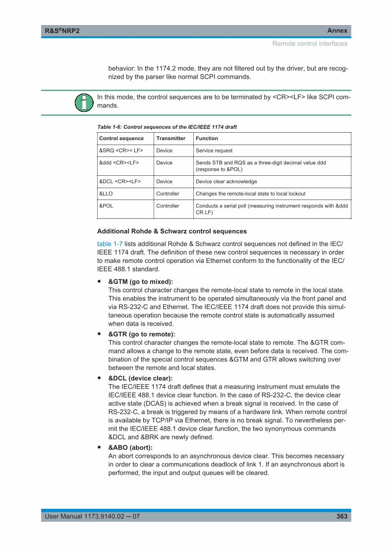
AnnexR&S®NRP2
363User Manual 1173.9140.02 ─ 07
behavior: In the 1174.2 mode, they are not filtered out by the driver, but are recog-nized by the parser like normal SCPI commands.
In this mode, the control sequences are to be terminated by <CR><LF> like SCPI com-mands.
Table 1-6: Control sequences of the IEC/IEEE 1174 draft
Control sequence Transmitter Function
&SRQ <CR>< LF> Device Service request
&ddd <CR><LF> Device Sends STB and RQS as a three-digit decimal value ddd(response to &POL)
&DCL <CR><LF> Device Device clear acknowledge
&LLO Controller Changes the remote-local state to local lockout
&POL Controller Conducts a serial poll (measuring instrument responds with &dddCR LF)
Additional Rohde & Schwarz control sequences
table 1-7 lists additional Rohde & Schwarz control sequences not defined in the IEC/IEEE 1174 draft. The definition of these new control sequences is necessary in orderto make remote control operation via Ethernet conform to the functionality of the IEC/IEEE 488.1 standard.
● >M (go to mixed):This control character changes the remote-local state to remote in the local state.This enables the instrument to be operated simultaneously via the front panel andvia RS-232-C and Ethernet. The IEC/IEEE 1174 draft does not provide this simul-taneous operation because the remote control state is automatically assumedwhen data is received.
● >R (go to remote):This control character changes the remote-local state to remote. The >R com-mand allows a change to the remote state, even before data is received. The com-bination of the special control sequences >M and GTR allows switching overbetween the remote and local states.
● &DCL (device clear):The IEC/IEEE 1174 draft defines that a measuring instrument must emulate theIEC/IEEE 488.1 device clear function. In the case of RS-232-C, the device clearactive state (DCAS) is achieved when a break signal is received. In the case ofRS-232-C, a break is triggered by means of a hardware link. When remote controlis available by TCP/IP via Ethernet, there is no break signal. To nevertheless per-mit the IEC/IEEE 488.1 device clear function, the two synonymous commands&DCL and &BRK are newly defined.
● &ABO (abort):An abort corresponds to an asynchronous device clear. This becomes necessaryin order to clear a communications deadlock of link 1. If an asynchronous abort isperformed, the input and output queues will be cleared.
Remote control interfaces
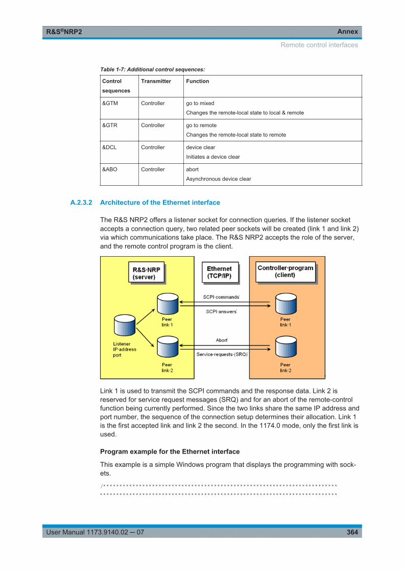
AnnexR&S®NRP2
364User Manual 1173.9140.02 ─ 07
Table 1-7: Additional control sequences:
Control
sequences
Transmitter Function
>M Controller go to mixed
Changes the remote-local state to local & remote
>R Controller go to remote
Changes the remote-local state to remote
&DCL Controller device clear
Initiates a device clear
&ABO Controller abort
Asynchronous device clear
A.2.3.2 Architecture of the Ethernet interface
The R&S NRP2 offers a listener socket for connection queries. If the listener socketaccepts a connection query, two related peer sockets will be created (link 1 and link 2)via which communications take place. The R&S NRP2 accepts the role of the server,and the remote control program is the client.
Link 1 is used to transmit the SCPI commands and the response data. Link 2 isreserved for service request messages (SRQ) and for an abort of the remote-controlfunction being currently performed. Since the two links share the same IP address andport number, the sequence of the connection setup determines their allocation. Link 1is the first accepted link and link 2 the second. In the 1174.0 mode, only the first link isused.
Program example for the Ethernet interface
This example is a simple Windows program that displays the programming with sock-ets.
/*************************************************************************************************************************************************
Remote control interfaces
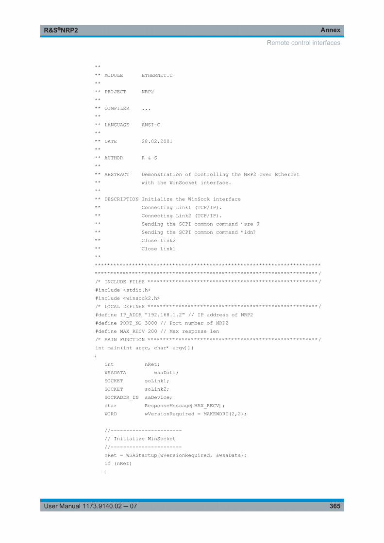
AnnexR&S®NRP2
365User Manual 1173.9140.02 ─ 07
**** MODULE ETHERNET.C**** PROJECT NRP2**** COMPILER ...**** LANGUAGE ANSI-C**** DATE 28.02.2001**** AUTHOR R & S**** ABSTRACT Demonstration of controlling the NRP2 over Ethernet** with the WinSocket interface.**** DESCRIPTION Initialize the WinSock interface** Connecting Link1 (TCP/IP).** Connecting Link2 (TCP/IP).** Sending the SCPI common command *sre 0** Sending the SCPI common command *idn?** Close Link2** Close Link1***************************************************************************************************************************************************//* INCLUDE FILES *******************************************************/#include <stdio.h>#include <winsock2.h>/* LOCAL DEFINES *******************************************************/#define IP_ADDR "192.168.1.2" // IP address of NRP2#define PORT_NO 3000 // Port number of NRP2#define MAX_RECV 200 // Max response len/* MAIN FUNCTION *******************************************************/int main(int argc, char* argv[]){ int nRet; WSADATA wsaData; SOCKET soLink1; SOCKET soLink2; SOCKADDR_IN saDevice; char ResponseMessage[MAX_RECV]; WORD wVersionRequired = MAKEWORD(2,2);
//----------------------- // Initialize WinSocket //----------------------- nRet = WSAStartup(wVersionRequired, &wsaData); if (nRet) {
Remote control interfaces
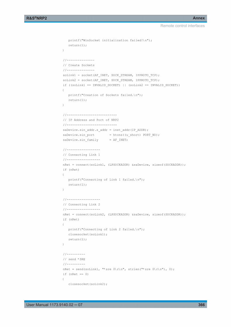
AnnexR&S®NRP2
366User Manual 1173.9140.02 ─ 07
printf("WinSocket initialization failed!\n"); return(1); }
//--------------- // Create Sockets //--------------- soLink1 = socket(AF_INET, SOCK_STREAM, IPPROTO_TCP); soLink2 = socket(AF_INET, SOCK_STREAM, IPPROTO_TCP); if ((soLink1 == INVALID_SOCKET) || (soLink2 == INVALID_SOCKET)) { printf("Creation of Sockets failed.\n"); return(1); }
//--------------------------- // IP Address and Port of NRP2 //--------------------------- saDevice.sin_addr.s_addr = inet_addr(IP_ADDR); saDevice.sin_port = htons((u_short) PORT_NO); saDevice.sin_family = AF_INET;
//------------------ // Connecting Link 1 //------------------ nRet = connect(soLink1, (LPSOCKADDR) &saDevice, sizeof(SOCKADDR)); if (nRet) { printf("Connecting of Link 1 failed.\n"); return(1); }
//------------------ // Connecting Link 2 //------------------ nRet = connect(soLink2, (LPSOCKADDR) &saDevice, sizeof(SOCKADDR)); if (nRet) { printf("Connecting of Link 2 failed.\n"); closesocket(soLink1); return(1); }
//---------- // send *SRE //---------- nRet = send(soLink1, "*sre 0\r\n", strlen("*sre 0\r\n"), 0); if (nRet == 0) { closesocket(soLink2);
Remote control interfaces
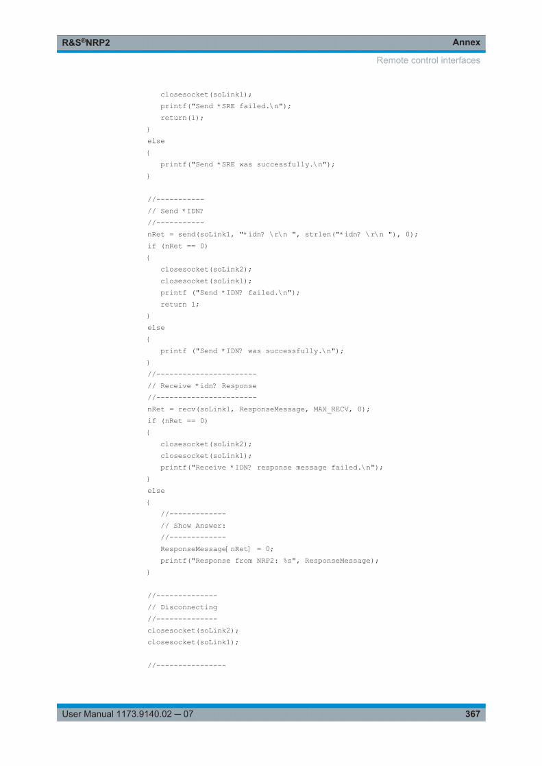
AnnexR&S®NRP2
367User Manual 1173.9140.02 ─ 07
closesocket(soLink1); printf("Send *SRE failed.\n"); return(1); } else { printf("Send *SRE was successfully.\n"); }
//----------- // Send *IDN? //----------- nRet = send(soLink1, "*idn? \r\n ", strlen("*idn? \r\n "), 0); if (nRet == 0) { closesocket(soLink2); closesocket(soLink1); printf ("Send *IDN? failed.\n"); return 1; } else { printf ("Send *IDN? was successfully.\n"); } //----------------------- // Receive *idn? Response //----------------------- nRet = recv(soLink1, ResponseMessage, MAX_RECV, 0); if (nRet == 0) { closesocket(soLink2); closesocket(soLink1); printf("Receive *IDN? response message failed.\n"); } else { //------------- // Show Answer: //------------- ResponseMessage[nRet] = 0; printf("Response from NRP2: %s", ResponseMessage); }
//-------------- // Disconnecting //-------------- closesocket(soLink2); closesocket(soLink1);
//----------------
Remote control interfaces
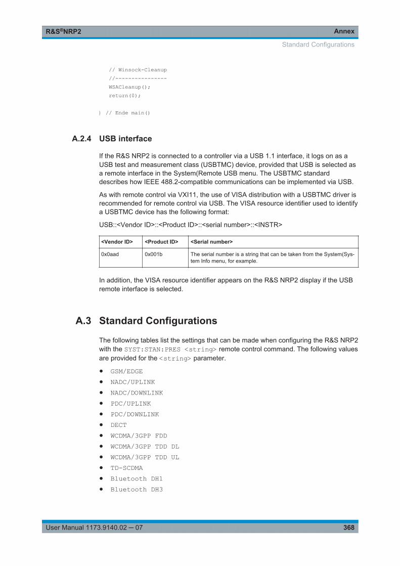
AnnexR&S®NRP2
368User Manual 1173.9140.02 ─ 07
// Winsock-Cleanup //---------------- WSACleanup(); return(0);
} // Ende main()
A.2.4 USB interface
If the R&S NRP2 is connected to a controller via a USB 1.1 interface, it logs on as aUSB test and measurement class (USBTMC) device, provided that USB is selected asa remote interface in the System(Remote USB menu. The USBTMC standarddescribes how IEEE 488.2-compatible communications can be implemented via USB.
As with remote control via VXI11, the use of VISA distribution with a USBTMC driver isrecommended for remote control via USB. The VISA resource identifier used to identifya USBTMC device has the following format:
USB::<Vendor ID>::<Product ID>::<serial number>::<INSTR>
<Vendor ID> <Product ID> <Serial number>
0x0aad 0x001b The serial number is a string that can be taken from the System(Sys-tem Info menu, for example.
In addition, the VISA resource identifier appears on the R&S NRP2 display if the USBremote interface is selected.
A.3 Standard Configurations
The following tables list the settings that can be made when configuring the R&S NRP2with the SYST:STAN:PRES <string> remote control command. The following valuesare provided for the <string> parameter.
● GSM/EDGE● NADC/UPLINK● NADC/DOWNLINK● PDC/UPLINK● PDC/DOWNLINK● DECT● WCDMA/3GPP FDD● WCDMA/3GPP TDD DL● WCDMA/3GPP TDD UL● TD-SCDMA● Bluetooth DH1● Bluetooth DH3
Standard Configurations
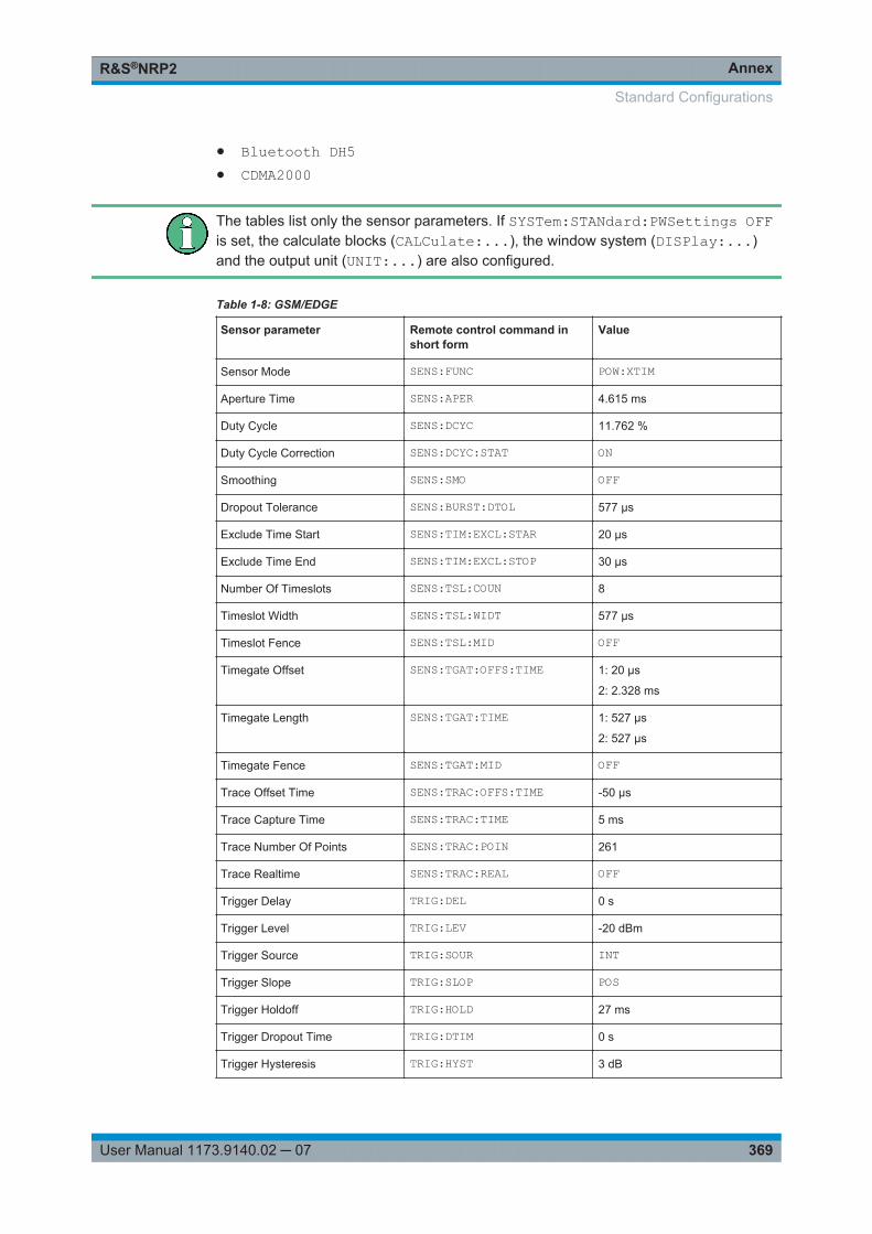
AnnexR&S®NRP2
369User Manual 1173.9140.02 ─ 07
● Bluetooth DH5● CDMA2000
The tables list only the sensor parameters. If SYSTem:STANdard:PWSettings OFFis set, the calculate blocks (CALCulate:...), the window system (DISPlay:...)and the output unit (UNIT:...) are also configured.
Table 1-8: GSM/EDGE
Sensor parameter Remote control command inshort form
Value
Sensor Mode SENS:FUNC POW:XTIM
Aperture Time SENS:APER 4.615 ms
Duty Cycle SENS:DCYC 11.762 %
Duty Cycle Correction SENS:DCYC:STAT ON
Smoothing SENS:SMO OFF
Dropout Tolerance SENS:BURST:DTOL 577 µs
Exclude Time Start SENS:TIM:EXCL:STAR 20 µs
Exclude Time End SENS:TIM:EXCL:STOP 30 µs
Number Of Timeslots SENS:TSL:COUN 8
Timeslot Width SENS:TSL:WIDT 577 µs
Timeslot Fence SENS:TSL:MID OFF
Timegate Offset SENS:TGAT:OFFS:TIME 1: 20 µs
2: 2.328 ms
Timegate Length SENS:TGAT:TIME 1: 527 µs
2: 527 µs
Timegate Fence SENS:TGAT:MID OFF
Trace Offset Time SENS:TRAC:OFFS:TIME -50 µs
Trace Capture Time SENS:TRAC:TIME 5 ms
Trace Number Of Points SENS:TRAC:POIN 261
Trace Realtime SENS:TRAC:REAL OFF
Trigger Delay TRIG:DEL 0 s
Trigger Level TRIG:LEV -20 dBm
Trigger Source TRIG:SOUR INT
Trigger Slope TRIG:SLOP POS
Trigger Holdoff TRIG:HOLD 27 ms
Trigger Dropout Time TRIG:DTIM 0 s
Trigger Hysteresis TRIG:HYST 3 dB
Standard Configurations
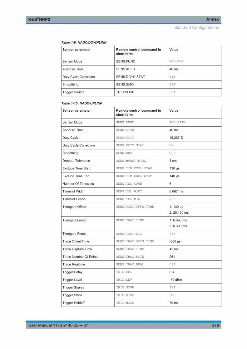
AnnexR&S®NRP2
370User Manual 1173.9140.02 ─ 07
Table 1-9: NADC/DOWNLINK
Sensor parameter Remote control command inshort form
Value
Sensor Mode SENS:FUNC POW:AVG
Aperture Time SENS:APER 40 ms
Duty Cycle Correction SENS:DCYC:STAT OFF
Smoothing SENS:SMO OFF
Trigger Source TRIG:SOUR EXT
Table 1-10: NADC/UPLINK
Sensor parameter Remote control command inshort form
Value
Sensor Mode SENS:FUNC POW:XTIM
Aperture Time SENS:APER 40 ms
Duty Cycle SENS:DCYC 16.267 %
Duty Cycle Correction SENS:DCYC:STAT ON
Smoothing SENS:SMO OFF
Dropout Tolerance SENS:BURST:DTOL 3 ms
Exclude Time Start SENS:TIM:EXCL:STAR 130 µs
Exclude Time End SENS:TIM:EXCL:STOP 140 µs
Number Of Timeslots SENS:TSL:COUN 6
Timeslot Width SENS:TSL:WIDT 6.667 ms
Timeslot Fence SENS:TSL:MID OFF
Timegate Offset SENS:TGAT:OFFS:TIME 1: 130 µs
2: 20.130 ms
Timegate Length SENS:TGAT:TIME 1: 6.390 ms
2: 6.390 ms
Timegate Fence SENS:TGAT:MID OFF
Trace Offset Time SENS:TRAC:OFFS:TIME -500 µs
Trace Capture Time SENS:TRAC:TIME 42 ms
Trace Number Of Points SENS:TRAC:POIN 261
Trace Realtime SENS:TRAC:REAL OFF
Trigger Delay TRIG:DEL 0 s
Trigger Level TRIG:LEV -30 dBm
Trigger Source TRIG:SOUR INT
Trigger Slope TRIG:SLOP POS
Trigger Holdoff TRIG:HOLD 79 ms
Standard Configurations
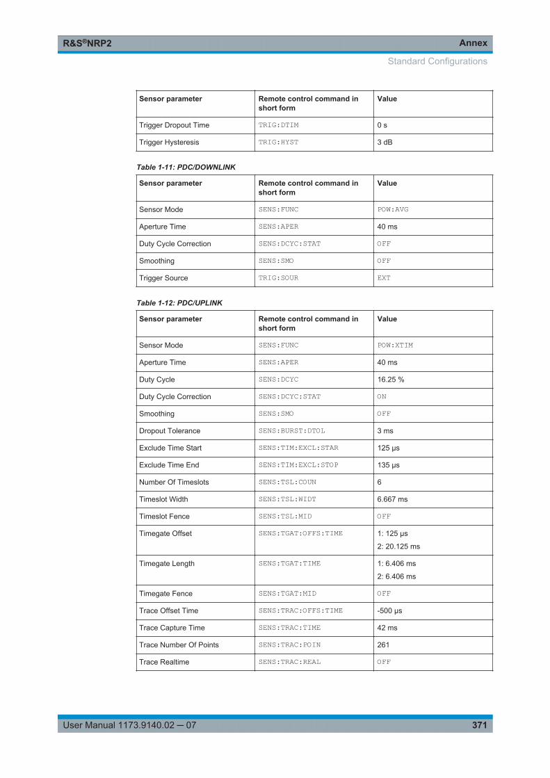
AnnexR&S®NRP2
371User Manual 1173.9140.02 ─ 07
Sensor parameter Remote control command inshort form
Value
Trigger Dropout Time TRIG:DTIM 0 s
Trigger Hysteresis TRIG:HYST 3 dB
Table 1-11: PDC/DOWNLINK
Sensor parameter Remote control command inshort form
Value
Sensor Mode SENS:FUNC POW:AVG
Aperture Time SENS:APER 40 ms
Duty Cycle Correction SENS:DCYC:STAT OFF
Smoothing SENS:SMO OFF
Trigger Source TRIG:SOUR EXT
Table 1-12: PDC/UPLINK
Sensor parameter Remote control command inshort form
Value
Sensor Mode SENS:FUNC POW:XTIM
Aperture Time SENS:APER 40 ms
Duty Cycle SENS:DCYC 16.25 %
Duty Cycle Correction SENS:DCYC:STAT ON
Smoothing SENS:SMO OFF
Dropout Tolerance SENS:BURST:DTOL 3 ms
Exclude Time Start SENS:TIM:EXCL:STAR 125 µs
Exclude Time End SENS:TIM:EXCL:STOP 135 µs
Number Of Timeslots SENS:TSL:COUN 6
Timeslot Width SENS:TSL:WIDT 6.667 ms
Timeslot Fence SENS:TSL:MID OFF
Timegate Offset SENS:TGAT:OFFS:TIME 1: 125 µs
2: 20.125 ms
Timegate Length SENS:TGAT:TIME 1: 6.406 ms
2: 6.406 ms
Timegate Fence SENS:TGAT:MID OFF
Trace Offset Time SENS:TRAC:OFFS:TIME -500 µs
Trace Capture Time SENS:TRAC:TIME 42 ms
Trace Number Of Points SENS:TRAC:POIN 261
Trace Realtime SENS:TRAC:REAL OFF
Standard Configurations
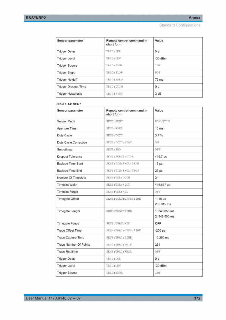
AnnexR&S®NRP2
372User Manual 1173.9140.02 ─ 07
Sensor parameter Remote control command inshort form
Value
Trigger Delay TRIG:DEL 0 s
Trigger Level TRIG:LEV -30 dBm
Trigger Source TRIG:SOUR INT
Trigger Slope TRIG:SLOP POS
Trigger Holdoff TRIG:HOLD 79 ms
Trigger Dropout Time TRIG:DTIM 0 s
Trigger Hysteresis TRIG:HYST 3 dB
Table 1-13: DECT
Sensor parameter Remote control command inshort form
Value
Sensor Mode SENS:FUNC POW:XTIM
Aperture Time SENS:APER 10 ms
Duty Cycle SENS:DCYC 3.7 %
Duty Cycle Correction SENS:DCYC:STAT ON
Smoothing SENS:SMO OFF
Dropout Tolerance SENS:BURST:DTOL 416.7 µs
Exclude Time Start SENS:TIM:EXCL:STAR 15 µs
Exclude Time End SENS:TIM:EXCL:STOP 25 µs
Number Of Timeslots SENS:TSL:COUN 24
Timeslot Width SENS:TSL:WIDT 416.667 µs
Timeslot Fence SENS:TSL:MID OFF
Timegate Offset SENS:TGAT:OFFS:TIME 1: 15 µs
2: 5.015 ms
Timegate Length SENS:TGAT:TIME 1: 348.055 ms
2: 348.000 ms
Timegate Fence SENS:TGAT:MID OFF
Trace Offset Time SENS:TRAC:OFFS:TIME -200 µs
Trace Capture Time SENS:TRAC:TIME 10.250 ms
Trace Number Of Points SENS:TRAC:POIN 261
Trace Realtime SENS:TRAC:REAL OFF
Trigger Delay TRIG:DEL 0 s
Trigger Level TRIG:LEV -30 dBm
Trigger Source TRIG:SOUR INT
Standard Configurations
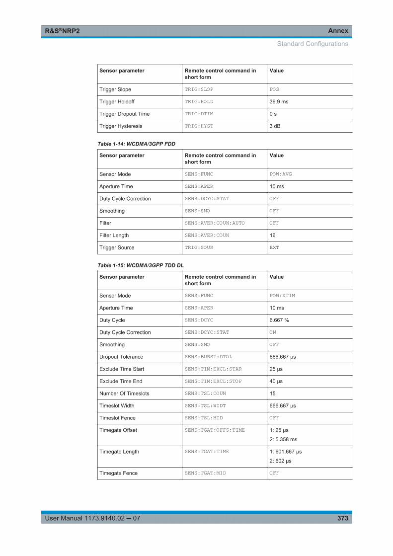
AnnexR&S®NRP2
373User Manual 1173.9140.02 ─ 07
Sensor parameter Remote control command inshort form
Value
Trigger Slope TRIG:SLOP POS
Trigger Holdoff TRIG:HOLD 39.9 ms
Trigger Dropout Time TRIG:DTIM 0 s
Trigger Hysteresis TRIG:HYST 3 dB
Table 1-14: WCDMA/3GPP FDD
Sensor parameter Remote control command inshort form
Value
Sensor Mode SENS:FUNC POW:AVG
Aperture Time SENS:APER 10 ms
Duty Cycle Correction SENS:DCYC:STAT OFF
Smoothing SENS:SMO OFF
Filter SENS:AVER:COUN:AUTO OFF
Filter Length SENS:AVER:COUN 16
Trigger Source TRIG:SOUR EXT
Table 1-15: WCDMA/3GPP TDD DL
Sensor parameter Remote control command inshort form
Value
Sensor Mode SENS:FUNC POW:XTIM
Aperture Time SENS:APER 10 ms
Duty Cycle SENS:DCYC 6.667 %
Duty Cycle Correction SENS:DCYC:STAT ON
Smoothing SENS:SMO OFF
Dropout Tolerance SENS:BURST:DTOL 666.667 µs
Exclude Time Start SENS:TIM:EXCL:STAR 25 µs
Exclude Time End SENS:TIM:EXCL:STOP 40 µs
Number Of Timeslots SENS:TSL:COUN 15
Timeslot Width SENS:TSL:WIDT 666.667 µs
Timeslot Fence SENS:TSL:MID OFF
Timegate Offset SENS:TGAT:OFFS:TIME 1: 25 µs
2: 5.358 ms
Timegate Length SENS:TGAT:TIME 1: 601.667 µs
2: 602 µs
Timegate Fence SENS:TGAT:MID OFF
Standard Configurations
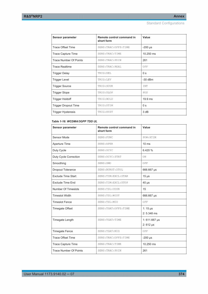
AnnexR&S®NRP2
374User Manual 1173.9140.02 ─ 07
Sensor parameter Remote control command inshort form
Value
Trace Offset Time SENS:TRAC:OFFS:TIME -200 µs
Trace Capture Time SENS:TRAC:TIME 10.250 ms
Trace Number Of Points SENS:TRAC:POIN 261
Trace Realtime SENS:TRAC:REAL OFF
Trigger Delay TRIG:DEL 0 s
Trigger Level TRIG:LEV -30 dBm
Trigger Source TRIG:SOUR INT
Trigger Slope TRIG:SLOP POS
Trigger Holdoff TRIG:HOLD 19.9 ms
Trigger Dropout Time TRIG:DTIM 0 s
Trigger Hysteresis TRIG:HYST 3 dB
Table 1-16: WCDMA/3GPP TDD UL
Sensor parameter Remote control command inshort form
Value
Sensor Mode SENS:FUNC POW:XTIM
Aperture Time SENS:APER 10 ms
Duty Cycle SENS:DCYC 6.420 %
Duty Cycle Correction SENS:DCYC:STAT ON
Smoothing SENS:SMO OFF
Dropout Tolerance SENS:BURST:DTOL 666.667 µs
Exclude Time Start SENS:TIM:EXCL:STAR 15 µs
Exclude Time End SENS:TIM:EXCL:STOP 40 µs
Number Of Timeslots SENS:TSL:COUN 15
Timeslot Width SENS:TSL:WIDT 666.667 µs
Timeslot Fence SENS:TSL:MID OFF
Timegate Offset SENS:TGAT:OFFS:TIME 1: 15 µs
2: 5.348 ms
Timegate Length SENS:TGAT:TIME 1: 611.667 µs
2: 612 µs
Timegate Fence SENS:TGAT:MID OFF
Trace Offset Time SENS:TRAC:OFFS:TIME -200 µs
Trace Capture Time SENS:TRAC:TIME 10.250 ms
Trace Number Of Points SENS:TRAC:POIN 261
Standard Configurations
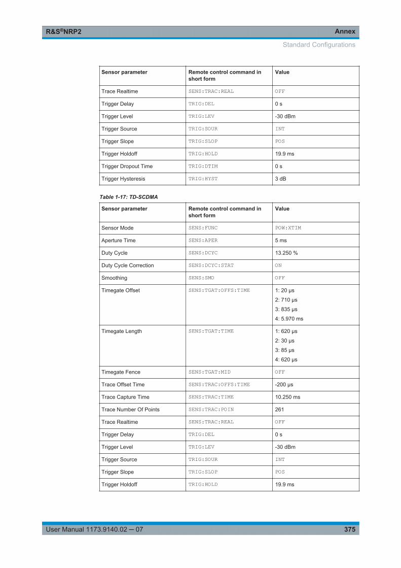
AnnexR&S®NRP2
375User Manual 1173.9140.02 ─ 07
Sensor parameter Remote control command inshort form
Value
Trace Realtime SENS:TRAC:REAL OFF
Trigger Delay TRIG:DEL 0 s
Trigger Level TRIG:LEV -30 dBm
Trigger Source TRIG:SOUR INT
Trigger Slope TRIG:SLOP POS
Trigger Holdoff TRIG:HOLD 19.9 ms
Trigger Dropout Time TRIG:DTIM 0 s
Trigger Hysteresis TRIG:HYST 3 dB
Table 1-17: TD-SCDMA
Sensor parameter Remote control command inshort form
Value
Sensor Mode SENS:FUNC POW:XTIM
Aperture Time SENS:APER 5 ms
Duty Cycle SENS:DCYC 13.250 %
Duty Cycle Correction SENS:DCYC:STAT ON
Smoothing SENS:SMO OFF
Timegate Offset SENS:TGAT:OFFS:TIME 1: 20 µs
2: 710 µs
3: 835 µs
4: 5.970 ms
Timegate Length SENS:TGAT:TIME 1: 620 µs
2: 30 µs
3: 85 µs
4: 620 µs
Timegate Fence SENS:TGAT:MID OFF
Trace Offset Time SENS:TRAC:OFFS:TIME -200 µs
Trace Capture Time SENS:TRAC:TIME 10.250 ms
Trace Number Of Points SENS:TRAC:POIN 261
Trace Realtime SENS:TRAC:REAL OFF
Trigger Delay TRIG:DEL 0 s
Trigger Level TRIG:LEV -30 dBm
Trigger Source TRIG:SOUR INT
Trigger Slope TRIG:SLOP POS
Trigger Holdoff TRIG:HOLD 19.9 ms
Standard Configurations
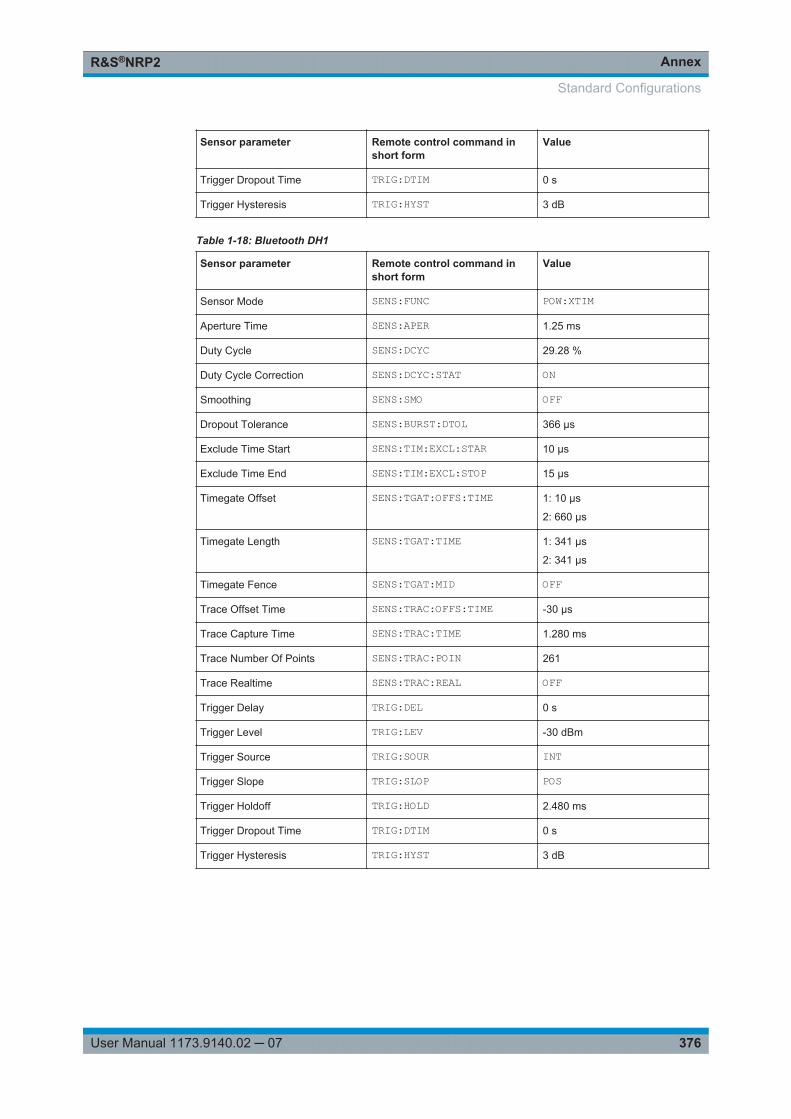
AnnexR&S®NRP2
376User Manual 1173.9140.02 ─ 07
Sensor parameter Remote control command inshort form
Value
Trigger Dropout Time TRIG:DTIM 0 s
Trigger Hysteresis TRIG:HYST 3 dB
Table 1-18: Bluetooth DH1
Sensor parameter Remote control command inshort form
Value
Sensor Mode SENS:FUNC POW:XTIM
Aperture Time SENS:APER 1.25 ms
Duty Cycle SENS:DCYC 29.28 %
Duty Cycle Correction SENS:DCYC:STAT ON
Smoothing SENS:SMO OFF
Dropout Tolerance SENS:BURST:DTOL 366 µs
Exclude Time Start SENS:TIM:EXCL:STAR 10 µs
Exclude Time End SENS:TIM:EXCL:STOP 15 µs
Timegate Offset SENS:TGAT:OFFS:TIME 1: 10 µs
2: 660 µs
Timegate Length SENS:TGAT:TIME 1: 341 µs
2: 341 µs
Timegate Fence SENS:TGAT:MID OFF
Trace Offset Time SENS:TRAC:OFFS:TIME -30 µs
Trace Capture Time SENS:TRAC:TIME 1.280 ms
Trace Number Of Points SENS:TRAC:POIN 261
Trace Realtime SENS:TRAC:REAL OFF
Trigger Delay TRIG:DEL 0 s
Trigger Level TRIG:LEV -30 dBm
Trigger Source TRIG:SOUR INT
Trigger Slope TRIG:SLOP POS
Trigger Holdoff TRIG:HOLD 2.480 ms
Trigger Dropout Time TRIG:DTIM 0 s
Trigger Hysteresis TRIG:HYST 3 dB
Standard Configurations
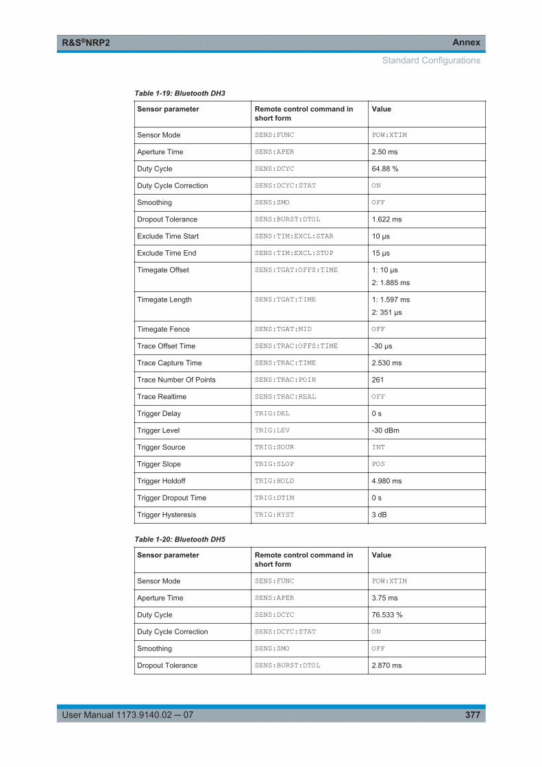
AnnexR&S®NRP2
377User Manual 1173.9140.02 ─ 07
Table 1-19: Bluetooth DH3
Sensor parameter Remote control command inshort form
Value
Sensor Mode SENS:FUNC POW:XTIM
Aperture Time SENS:APER 2.50 ms
Duty Cycle SENS:DCYC 64.88 %
Duty Cycle Correction SENS:DCYC:STAT ON
Smoothing SENS:SMO OFF
Dropout Tolerance SENS:BURST:DTOL 1.622 ms
Exclude Time Start SENS:TIM:EXCL:STAR 10 µs
Exclude Time End SENS:TIM:EXCL:STOP 15 µs
Timegate Offset SENS:TGAT:OFFS:TIME 1: 10 µs
2: 1.885 ms
Timegate Length SENS:TGAT:TIME 1: 1.597 ms
2: 351 µs
Timegate Fence SENS:TGAT:MID OFF
Trace Offset Time SENS:TRAC:OFFS:TIME -30 µs
Trace Capture Time SENS:TRAC:TIME 2.530 ms
Trace Number Of Points SENS:TRAC:POIN 261
Trace Realtime SENS:TRAC:REAL OFF
Trigger Delay TRIG:DEL 0 s
Trigger Level TRIG:LEV -30 dBm
Trigger Source TRIG:SOUR INT
Trigger Slope TRIG:SLOP POS
Trigger Holdoff TRIG:HOLD 4.980 ms
Trigger Dropout Time TRIG:DTIM 0 s
Trigger Hysteresis TRIG:HYST 3 dB
Table 1-20: Bluetooth DH5
Sensor parameter Remote control command inshort form
Value
Sensor Mode SENS:FUNC POW:XTIM
Aperture Time SENS:APER 3.75 ms
Duty Cycle SENS:DCYC 76.533 %
Duty Cycle Correction SENS:DCYC:STAT ON
Smoothing SENS:SMO OFF
Dropout Tolerance SENS:BURST:DTOL 2.870 ms
Standard Configurations
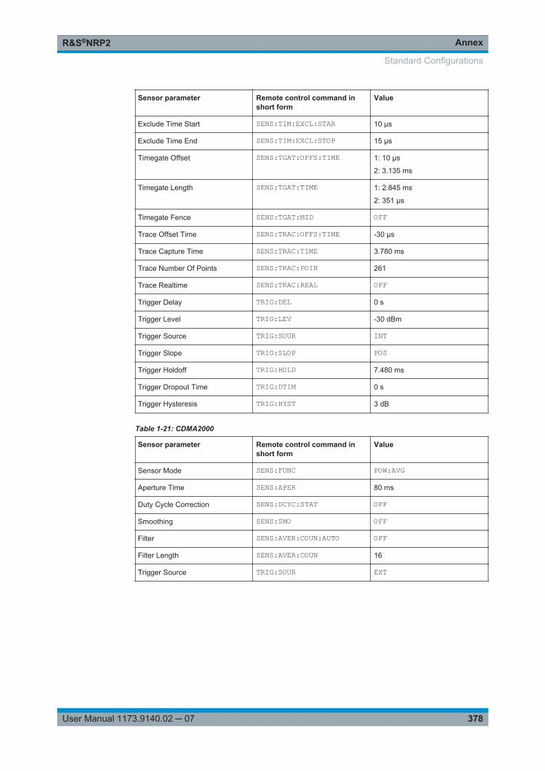
AnnexR&S®NRP2
378User Manual 1173.9140.02 ─ 07
Sensor parameter Remote control command inshort form
Value
Exclude Time Start SENS:TIM:EXCL:STAR 10 µs
Exclude Time End SENS:TIM:EXCL:STOP 15 µs
Timegate Offset SENS:TGAT:OFFS:TIME 1: 10 µs
2: 3.135 ms
Timegate Length SENS:TGAT:TIME 1: 2.845 ms
2: 351 µs
Timegate Fence SENS:TGAT:MID OFF
Trace Offset Time SENS:TRAC:OFFS:TIME -30 µs
Trace Capture Time SENS:TRAC:TIME 3.780 ms
Trace Number Of Points SENS:TRAC:POIN 261
Trace Realtime SENS:TRAC:REAL OFF
Trigger Delay TRIG:DEL 0 s
Trigger Level TRIG:LEV -30 dBm
Trigger Source TRIG:SOUR INT
Trigger Slope TRIG:SLOP POS
Trigger Holdoff TRIG:HOLD 7.480 ms
Trigger Dropout Time TRIG:DTIM 0 s
Trigger Hysteresis TRIG:HYST 3 dB
Table 1-21: CDMA2000
Sensor parameter Remote control command inshort form
Value
Sensor Mode SENS:FUNC POW:AVG
Aperture Time SENS:APER 80 ms
Duty Cycle Correction SENS:DCYC:STAT OFF
Smoothing SENS:SMO OFF
Filter SENS:AVER:COUN:AUTO OFF
Filter Length SENS:AVER:COUN 16
Trigger Source TRIG:SOUR EXT
Standard Configurations
AnnexR&S®NRP2
379User Manual 1173.9140.02 ─ 07
A.4 Programming Measurements
A.4.1 Measuring with high-level commands
The R&S NRP2 is based on the instrument model defined in the SCPI 1999.0 stand-ard. This model provides a number of logic blocks that can be configured via remote-control commands. The R&S NRP2 is provided with high-level measurement com-mands that automatically perform the most important settings and simplify measure-ments, thus making it unnecessary to completely configure these blocks for each mea-surement. Only the high-level commands are described, starting with the simplestcommand, which is expanded in the following sections.
Note the following for the syntax of commands: There is a short and a long form for thecommands. The short form is normally used. However, commands are sometimes indi-cated in their long form so that their meaning is easier to understand. The R&S NRP2makes no distinction between upper case and lower case letters; they are only used todistinguish between the short and long form.
A.4.1.1 The simplest measurement
The simplest way to obtain a measured value is to use the high-level measurementcommand
MEAS?,
which configures sensor 1 in the ContAv mode, starts a measurement and always out-puts a result that is stored in the output queue.
The following settings are performed:● INIT:CONT OFF● TRIG:SOUR IMM● TRIG:COUN 1● TRIG:DEL:AUTO ON● SENS:AVER:STAT ON● SENS:AVER:COUN:AUTO ON● SENS:AVER:COUN:AUTO:TYPE RES● SENS:AVER:COUN:AUTO:RES 3● CALC:MATH "(SENS1)"● CALC:REL:STAT OFFThe command can also be used with a list of parameters, which are separated by acomma and allow the measurement accuracy and the addressed sensor to beselected:
MEAS? DEF, <resolution>, <source_list>The first parameter should always assume the DEF value; it is ignored and is availableonly for reasons of compatibility.
Programming Measurements
AnnexR&S®NRP2
380User Manual 1173.9140.02 ─ 07
The second parameter may assume the values 1, 2, 3 and 4. It specifies the number ofplaces up to which the measurement result should be noise-free. With linear units, thesetting corresponds to the number of significant places that are noise-free; with loga-rithmic units, 1, 2, 3 and 4 correspond to a resolution of 1, 0.1, 0.01 and 0.001 (numberof decimal places). With a <resolution> of 3, two decimal places are thus noise-freewith logarithmic display. The default setting is 3.
The third parameter selects a sensor. It has the syntax (@n), where n can assume thevalues 1 to 4. The default setting is (@1).
A.4.1.2 Relative measurements
If the measurement results are to be output not as absolute values, but relative to areference value, the keyword :RELative can be added to the measurement com-mand. The result is then divided by a value that was previously set by means ofCALC:REL:POW or CALC:REL:AUTO ONCE.
MEAS?CALC:REL:AUTO ONCEMEAS:REL?The first MEAS command determines the reference value, which is acquired and storedwith CALC:REL:AUTO ONCE. The second measurement command MEAS:REL? andall other MEAS:REL? commands will divide the absolute measured value by the storedreference value.
CALC:REL:POW <float_value> is used to define such a reference value.
CALC:REL:POW 0 DBMMEAS:REL?All measured values are then divided by 0 dBm (1 mW) prior to being transferred to theuser.
The following section describes an extension of the MEAS command in which the resultno longer carries a power unit, but represents a power ratio. The reference value alsomust have a power unit and be set with CALC:REL:RAT. The R&S NRP2 stores thereference values for power values and power ratios independently of each other andautomatically uses the correct reference value depending on the unit of the measure-ment result.
The CALC:REL command is available for entering the reference value. It assumes anumeric parameter whose unit is determined from the current device settings. Thiscommand is provided only for reasons of compatibility and should not be used unlessavoidable.
A.4.1.3 Processing the results of two sensors
The R&S NRP2 offers measurement commands for processing the results of two sen-sors. The calculated result can also be partly referenced to a stored reference value.
Programming Measurements
AnnexR&S®NRP2
381User Manual 1173.9140.02 ─ 07
The measurement commands are obtained by adding one of the following keywords:
:DIFF (difference)
:DIFF:REL (difference with reference value)
:RAT (ratio)
:RAT:REL (ratio with reference value)
:SWR (standing wave ratio)
:RLOS (return loss)
:REFL (reflection coefficient)
The list of parameters is modified for these commands since two sensors have to beentered in the <source_list>.
Example: MEAS:RAT DEF,3,(@1),(@4)A CALCulate block is used for processing the measured values. Each CALCulateblock has two input channels called the primary and secondary channel. In the aboveexample, the primary channel is assigned sensor 1 and the secondary channel sensor4 via the <source_list>. The measurement result is the ratio of the results fromsensors 1 and 4.
Example: MEAS:SWR DEF,2,(@1),(@2)It is assumed that sensor 1 delivers the forward power of a wave and sensor 2 thereflected power of a wave. The measurement result represents the SWR of the twopower values:
1/@/2@1
1/@/2@1
P
Note that the unit is automatically set to percent (refer to chapter A.4.1.5, "Selectingthe output unit for measured values", on page 383
A.4.1.4 Selecting a measurement mode
Other MEAS commands are available for measurements to be performed in a modeother than the "ContAv" mode. The short form of these commands is obtained by add-ing a keyword for the measurement mode to keyword MEAS.
Timeslot measurement:
MEAS:TSLot?<tslot_width>,<no_slots>,<start_exclude>,<stop_exclude>BurstAv measurement:
MEAS:BURSt? <dtolerance>,<start_exclude>,<stop_exclude>
Programming Measurements
AnnexR&S®NRP2
382User Manual 1173.9140.02 ─ 07
Trace measurement:
MEAS:XTIMe? (<scope_size>),<capture_time>Measurement in the ContAv mode with data buffering:
MEAS:ARRay?<tslot_width>,<no_slots>,<start_exclude>,<stop_exclude>
In the Timeslot mode, the trigger source is set to EXTernal. In the "BurstAv" mode, itis not modified but ignored. Triggering in response to the signal is performed as ifTRIGger:SOURce INTernal were set.
These commands have the specified parameters, whose meanings are explained inthe operating manual. In addition, parameters DEF, <resolution>, <source_list>can be optionally specified as for the MEAS? command.
Example: MEAS:TSLot? 577 us, 8, 18 us, 18 usA timeslot measurement of a GSM signal is performed (8 timeslots with a length of577 µs each). 18 µs at the beginning and the end of the timeslots are ignored. Themeasurement is carried out with sensor 1 (default). The instrument is triggered by anexternal signal, which must be routed to the R&S NRP2 rear panel via the trigger input.The measurement result is a list of 8 measured values separated by a comma for thetimeslots.
Example: MEAS:BURSt? 5 us, 10 us, 0 us, DEF, 3, (@2)Sensor 2 measures in the BurstAv mode. Triggering (in response to a rising edge) isinternal. At the beginning of the power pulse, 10 µs are ignored to avoid overshoots inthe signal, which could distort the measurement result. If the power falls below the trig-ger level but does not exceed 5 µs (dropout time) the measurement will not be stop-ped. The measurement result is noise-free within the first 3 places and it is measuredwith sensor 2 ((@2)).
Example: MEAS:XTIMe? (256), 577 usWithin the next 577 µs, 256 measured values are recorded and displayed with respectto time in te same manner as with an oscilloscope in order to display the power charac-teristics. There is no triggering (TRIG:SOUR IMM); the measurements are started afterthe command is received from the R&S NRP2. After a partial measurement has beencompleted, the next one is started. If the trigger source setting is to be changed,MEAS:XTIMe? must be replaced by the CONF:XTIMe and READ:XTIMe? commands,between which user-defined settings can be performed. Dividing MEAS? into the CONFand READ? commands is described further down. The measurement result is a list of256 measured values separated by a comma.
Programming Measurements
AnnexR&S®NRP2
383User Manual 1173.9140.02 ─ 07
Example: MEAS:ARRay? (1000)1000 measured values are recorded in the ContAv mode. After termination of the lastmeasurement, the results are stored in the output queue. There is no triggering as inthe ContAv mode. The measurement result is a list of 1000 measured values separa-ted by a comma.
The keywords for processing two sensors can be added to the MEAS:TSL, MEAS:BURSand MEAS:ARRay commands, but the :SWR,:RLOS and :REFL functions are not avail-able.
Example: MEAS:TSL:RAT? 577 us, 8, 18 us, 18 us, DEF, 3, (@1), (@3)The above timeslot example is extended to two sensors. The measurement result is alist of 8 measured values separated by a comma for the 8 timeslots; these values wereobtained by division from the measured values of sensors 1 and 3.
A.4.1.5 Selecting the output unit for measured values
So far, no information has been given on the unit of the measured values. It is possibleto modify the output unit of the measured values. A distinction is made as to whetherthe result represents a power or a power ratio. Relative measurements always deliverpower ratios. This also applies to the :RATio, :SWR, :RLOS and :REFL functions. Theunits are set by means of the following commands:
UNIT:POWer DBM | W | DBUVand
UNIT:RATio DB | DPCT | OThe default settings are DBM for power values and DB for power ratios.
Physical
unit
SCPI
notation
Meaning
dBm DBM Power in dB referenced to 1 mW: x / W = 10 log ( x / (1 mW) ) / dBm
Watt W
dBµV DBUV Power in dB referred to (1µV)2 / 50 (: x dBm ( (x + 107) dBµV
dB DB
Δ% DPCT Deviation from 100% in %: x (% = Δx + 100) %
1 O
When the :SWR, :RLOS and :REFL functions are used, the output unit, however, isimplicitly set by the MEAS command:
Programming Measurements
AnnexR&S®NRP2
384User Manual 1173.9140.02 ─ 07
Measurement function Output unit
:SWR O
:RLOS DB
:REFL O
The UNIT commands affect the parameters of the following commands:CALC:LIMit:UPPer, CALC:LIMit:LOWer, CALC:RELative, DISP:METer:UPPerand DISP:METer:LOWer.
A.4.1.6 Division of MEAS?
MEAS? can be divided into other high-level measurement commands.
MEAS? ⇔ CONF [<parameters list>]READ? [<parameters list>]
The CONF command configures the measurement, whereas READ? starts the measure-ment, and calculates and provides the result.
This division offers two advantages:● The measurement has to be configured only once and several measurements (with
several READ? commands) can be performed in succession. This means betterperformance as compared to measurements performed with MEAS?, since the timefor configuring the measurement is only used once.
● After CONF, settings can be adapted to user's requirements by means of low-levelcommands (see below).
If a list of parameters is indicated for the READ command, it must correspond to the listfor the preceding CONF command.
After a measurement has been completed, i.e. the data from the sensors is available, itis sometimes interesting to evaluate this data several times without starting a newmeasurement each time. Since this is not possible with the above commands, theREAD? command can be replaced by the INIT and FETCh? commands.
READ? ⇔ INITFETCh? [<list of parameters>]
FETCh? evaluates existing data if the data is valid. FETCh? may select another calcu-lation function if the measurement can be evaluated with the available measured data.
Programming Measurements
AnnexR&S®NRP2
385User Manual 1173.9140.02 ─ 07
Example: The following sequence of commands provides the difference between measured val-ues from sensors 1 and 2 by means of FETCh:DIFF?, which measure in the ContAvmode as the default setting.
CONF:DIFFINIT:ALLFETCh:DIFF? 'Response: valid resultFETCh:RAT? 'Response: valid resultFETCh:BURst? 'Response: -221, "Settings conflict"
The FETCh:RAT? command then delivers the ratios of the two measured values. Thisis possible without a new measurement, since the required data is available. The lastFETCh command requires a result that was measured in the BurstAv mode. Such ameasured value is not available and thus, this command will generate a SCPI error(-221, "Settings conflict").
FETCh? immediately delivers a measured value if a valid result is available. If no mea-sured value is available, the R&S NRP2 waits for such a value and then answers thequery. During this time, no other command should be sent to the R&S NRP2, since thequery has to be answered first. If a command is sent to the R&S NRP2, the SCPI error-410, "Query interrupted", is output.
However, FETCh? should wait only if a measurement result is expected, since com-mand processing is blocked if a command is not answered. If FETCh? is executedalthough no measured values are expected, the SCPI error -214, "Trigger deadlock", isoutput. This may occur if the trigger source is set to BUS or HOLD with low-levelTRIG:SOUR and FETCh? immediately follows INIT.
Example
CONFTRIG:SOUR BUSINITFETCh? 'Response: -214, "Trigger deadlock",
*TRG or GET is not possible if FETCh? is waiting.
A.4.2 Trigger state system
The accuracy of a result largely depends on how accurately the sequence of a mea-surement can be determined. TheR&S NRP2 manages a trigger state system to SCPI1999.0 for each sensor to define the exact start and stop time of a measurement. Thissystem defines the sequence of a measurement cycle. 4 different device states aredefined in the trigger state system implemented in the R&S NRP2.
Programming Measurements

AnnexR&S®NRP2
386User Manual 1173.9140.02 ─ 07
IDLE The R&S NRP2 is in the idle state and performs no measurement. On power-upof the R&S NRP2, it is in the LOCAL mode and in the IDLE state. All connectedsensors are set to INIT:CONT ON to allow measurements to be continuouslydisplayed. Thus, the IDLE state is exited and the instrument is again in this stateif INIT:CONT OFF is sent via the remote control.
INITIATED This state is a transition state, which is exited immediately after it has beenentered. It has been defined so as to allow the user to decide whether the nextmeasurement cycle is to be immediately started (INIT:CONT ON or all cyclesdefined via TRIG:COUNT have not yet been processed) or the R&S NRP2returns to the IDLE state. The state is only entered internally and is not noticedby the user.
WAIT_FOR_TRG The R&S NRP2 waits for a trigger event. The source for this event is set viaTRIG:SOUR. When the event defined in this way occurs, the enters theMEASURING state.
MEASURING As long as the R&S NRP2 measures data, it remains in this state and exits itimmediately after completion of the measurement.
BUS HOLDINTEXT IMMTRIG:SOUR
*TRG
, GE
Tor
TRI
G:IM
M
TRIG
:IMM
or
Trig
ger s
igna
l
TRIG
:IMM
INIT:CONT?ABORT ON
OFF
MEASURING
WAIT_FOR_TRG
INITIATED
IDLE *RST, PowerOnINIT:IMMINIT:CONT ON
?
Fig. 1-5: Overview of basic relationships in the trigger state system
Programming Measurements
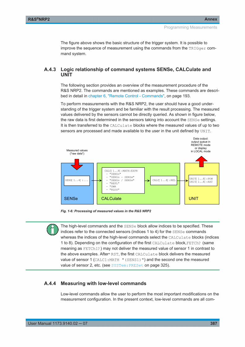
AnnexR&S®NRP2
387User Manual 1173.9140.02 ─ 07
The figure above shows the basic structure of the trigger system. It is possible toimprove the sequence of measurement using the commands from the TRIGger com-mand system.
A.4.3 Logic relationship of command systems SENSe, CALCulate andUNIT
The following section provides an overview of the measurement procedure of theR&S NRP2. The commands are mentioned as examples. These commands are descri-bed in detail in chapter 6, "Remote Control - Commands", on page 193.
To perform measurements with the R&S NRP2, the user should have a good under-standing of the trigger system and be familiar with the result processing. The measuredvalues delivered by the sensors cannot be directly queried. As shown in figure below,the raw data is first determined in the sensors taking into account the SENSe settings.It is then transferred to the CALCulate blocks where the measured values of up to twosensors are processed and made available to the user in the unit defined by UNIT.
CALC[1..8]:MATH:EXPR - "SENSn" - "SENSn - SENSm" - "SENSn / SENSm" - "REFL" - "SWR - "RLOS"
CALC[1..8]:REL UNIT[1..8]:POWUNIT[1..8]:RAT
Data output:output queue inREMOTE mode
or displayin LOCAL modeMeasured values
("raw data")
CALCulate UNITSENSe
SENS[1..4]:...
Fig. 1-6: Processing of measured values in the R&S NRP2
The high-level commands and the SENSe block allow indices to be specified. Theseindices refer to the connected sensors (indices 1 to 4) for the SENSe commandswhereas the indices of the high-level commands select the CALCulate blocks (indices1 to 8). Depending on the configuration of the first CALCulate block,FETCh? (samemeaning as FETCh1?) may not deliver the measured value of sensor 1 in contrast tothe above examples. After*RST, the first CALCulate block delivers the measuredvalue of sensor 1 (CALC1:MATH "(SENS1)") and the second one the measuredvalue of sensor 2, etc. (see SYSTem:PRESet on page 325).
A.4.4 Measuring with low-level commands
Low-level commands allow the user to perform the most important modifications on themeasurement configuration. In the present context, low-level commands are all com-
Programming Measurements
AnnexR&S®NRP2
388User Manual 1173.9140.02 ─ 07
mands that do not belong to high-level commands. These are in particular the com-mands of the SENSe, TRIGger and CALCulate systems. Since the high-level com-mands combine different low-level commands, they allow a simpler configuration ofmeasurements.
Each measurement configuration should begin with the *RST command, which setsthe R&S NRP2 to a defined output state. The accurate settings are described in thedocumentation of remote control command SYSTem:PRESet.
The most important settings are listed below:● Continuous measurements are stopped (INIT:CONT OFF)● Offset correction are deactivated (SENSe:CORRection:OFFSet:STATe
OFF,SENSe:CORRection:DCYCle:STATe OFF,SENSe:CORRection:FDOFfset:STATe OFF).
● All other settings of the SENSe system depend on the sensor used and are speci-fied in the corresponding manual.
● The first 4 CALCulate blocks are set to sensors 1 to 4 (CALCulate<n>:MATH"(SENSn)").
● The values are measured as absolute values (CALulate:RELative:STATeOFF).
● Logarithmic units are used (UNIT:POWer dBm and UNIT:RATio dB).
A.4.4.1 The simplest measurement
The fastest way to obtain a result is to use the following sequence of commands
*RSTINITFETCh?
Normally, *RST will set the "ContAv" mode. The concept of smart-sensor technologyprovides that each sensor determines the reset values of the assigned SENSe andTRIGger block. Thus, another mode than ContAv may come after *RST with futuresensors. Information is provided in the operating manual of the sensor used.
INIT initiates the measurement. After *RST, the trigger system is set to "straightthrough" (TRIG:SOUR IMM) so that the trigger system state changes to MEASURINGvia INITIATED and WAIT_FOR_TRG. After the measurement has been completed,FETCh? delivers the result to the output queue from which it can be fetched.
A.4.4.2 Configuration of the trigger system
Trigger source
After a measurement is started with INIT, the state WAIT_FOR_TRG is entered. This isa preliminary stage to the measurement, which has been initiated so that the measure-ment may start with high accuracy at a defined point in time. For this purpose, differentsources can be defined for the trigger event, which triggers the measurement. In man-
Programming Measurements
AnnexR&S®NRP2
389User Manual 1173.9140.02 ─ 07
ual operation, a trigger event is not expected in the "ContAv" mode. Since the mea-surement is to be performed continuously, the trigger source (TRIGger:SOURce) isset to IMMediate.
If triggering needs to occur in response to a rising signal edge, the trigger system hasto be configured with TRIG:SOUR INT and TRIG:SLOP POS:
Example
*RSTTRIG:SOUR INT 'triggering in response to a signal edgeTRIG:SLOP POS 'triggering in response to a rising signal edgeINITFETCh?
The settings of commands TRIG:SOUR and TRIG:SLOP are ignored in the "BurstAv"mode. In this mode the beginning and the end of the power pulse are automaticallyrecognized. For this reason, the instrument always triggers INTernal even ifTRIG:SOUR has a different setting.
If a trigger signal is to be routed to the instrument rear panel via the external triggerconnector, the trigger source has to be configured with TRIG:SOUR EXT.
Example
*RSTTRIG:SOUR EXT 'triggering in response to the edge of an external signalTRIG:SLOP POS 'triggering in response to a rising signal edgeINITFETCh?
TRIG:SOUR BUS can be set if measurements are to be started with *TRG or GET. Thisprocedure is provided by standard IEEE 488.2, which stipulates that *TRG or GET canalso be used to perform complete measurements. This includes the generation of ananswer, the measurement result. In the R&S NRP2, *TRG does not have this meaning:*TRG only executes a trigger event and thus only causes the status transitions fromWAIT_FOR_TRG to MEASURING. *TRG delivers no measurement result and has noeffect if TRIG:SOUR is not set to BUS or if the instrument is not in the stateWAIT_FOR_TRG. The latter situation applies, for example, if the R&S NRP2 is IDLE,i.e. INIT:CONT ON is not set nor was INIT executed.
Delay, Holdoff
Normally, the measurement immediately starts after the trigger event has been execu-ted. This may not be desirable if the measurement is to be started before or after thetrigger point. The start of the measurement with reference to the trigger point can beoffset using the TRIG:DEL command. A negative sign means that the measurementbegins before the trigger point. This is possible because the sensors store samplingvalues for a while and can use past values when the measurement is started. Thecommand is also used when overshoots are to be ignored at the beginning of a powerpulse.
Programming Measurements
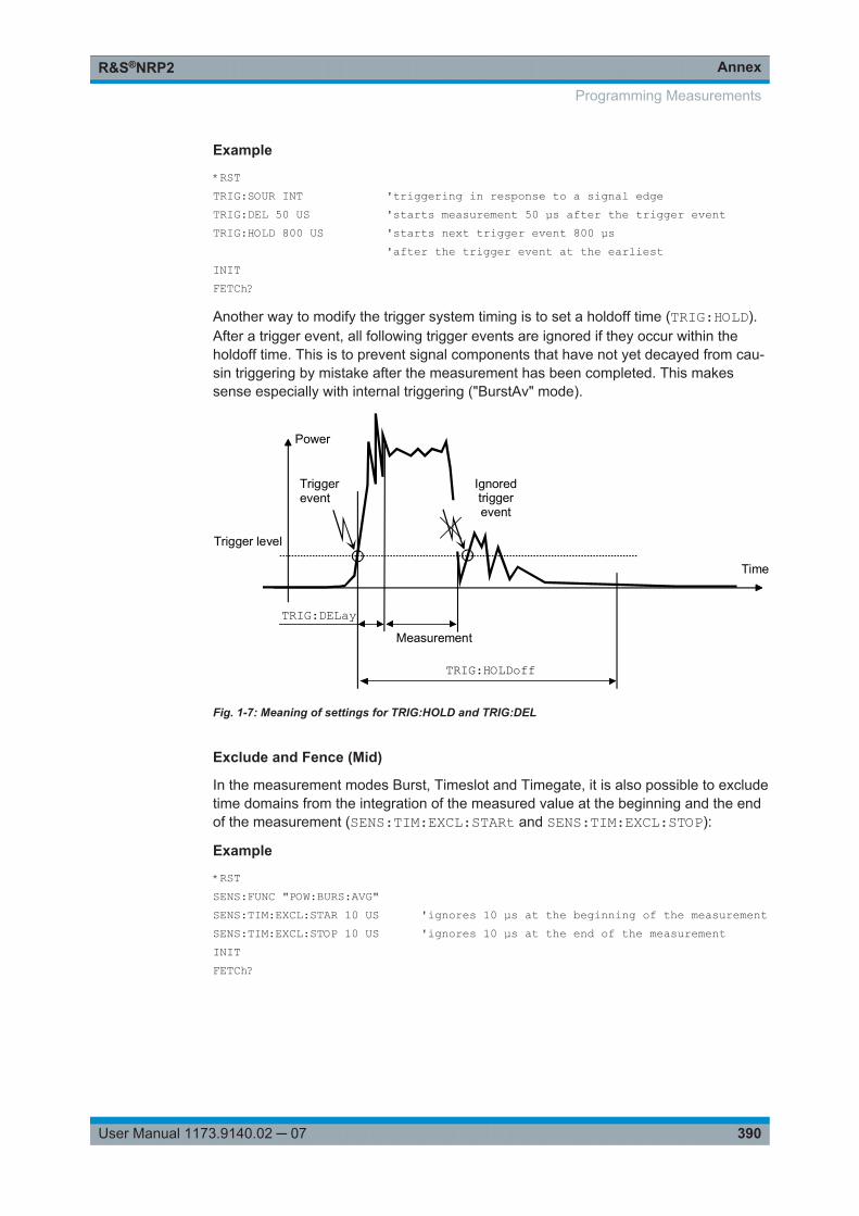
AnnexR&S®NRP2
390User Manual 1173.9140.02 ─ 07
Example
*RSTTRIG:SOUR INT 'triggering in response to a signal edgeTRIG:DEL 50 US 'starts measurement 50 µs after the trigger eventTRIG:HOLD 800 US 'starts next trigger event 800 µs 'after the trigger event at the earliestINITFETCh?
Another way to modify the trigger system timing is to set a holdoff time (TRIG:HOLD).After a trigger event, all following trigger events are ignored if they occur within theholdoff time. This is to prevent signal components that have not yet decayed from cau-sin triggering by mistake after the measurement has been completed. This makessense especially with internal triggering ("BurstAv" mode).
Ignoredtriggerevent
Power
Time
TRIG:HOLDoff
TRIG:DELay
Triggerevent
Measurement
Trigger level
Fig. 1-7: Meaning of settings for TRIG:HOLD and TRIG:DEL
Exclude and Fence (Mid)
In the measurement modes Burst, Timeslot and Timegate, it is also possible to excludetime domains from the integration of the measured value at the beginning and the endof the measurement (SENS:TIM:EXCL:STARt and SENS:TIM:EXCL:STOP):
Example
*RSTSENS:FUNC "POW:BURS:AVG"SENS:TIM:EXCL:STAR 10 US 'ignores 10 µs at the beginning of the measurementSENS:TIM:EXCL:STOP 10 US 'ignores 10 µs at the end of the measurementINITFETCh?
Programming Measurements
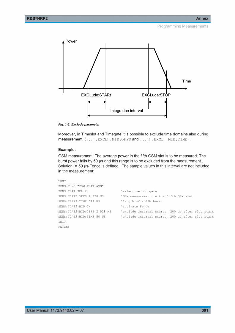
AnnexR&S®NRP2
391User Manual 1173.9140.02 ─ 07
Integration interval
EXCLude:STARt EXCLude:STOP
Power
Time
Fig. 1-8: Exclude parameter
Moreover, in Timeslot and Timegate it is possible to exclude time domains also duringmeasurement. (...[:EXCL]:MID:OFFS and ...:[:EXCL]:MID:TIME).
Example: GSM measurement: The average power in the fifth GSM slot is to be measured. Theburst power fails by 50 µs and this range is to be excluded from the measurement..Solution: A 50 µs-Fence is defined.. The sample values in this interval are not includedin the measurement:
*RSTSENS:FUNC "POW:TGAT:AVG"SENS:TGAT:SEL 2 'select second gateSENS:TGAT2:OFFS 2.328 MS 'GSM measurement in the fifth GSM slotSENS:TGAT2:TIME 527 US 'length of a GSM burstSENS:TGAT2:MID ON 'activate FenceSENS:TGAT2:MID:OFFS 2.528 MS 'exclude interval starts, 200 µs after slot startSENS:TGAT2:MID:TIME 50 US 'exclude interval starts, 200 µs after slot startINITFETCh?
Programming Measurements
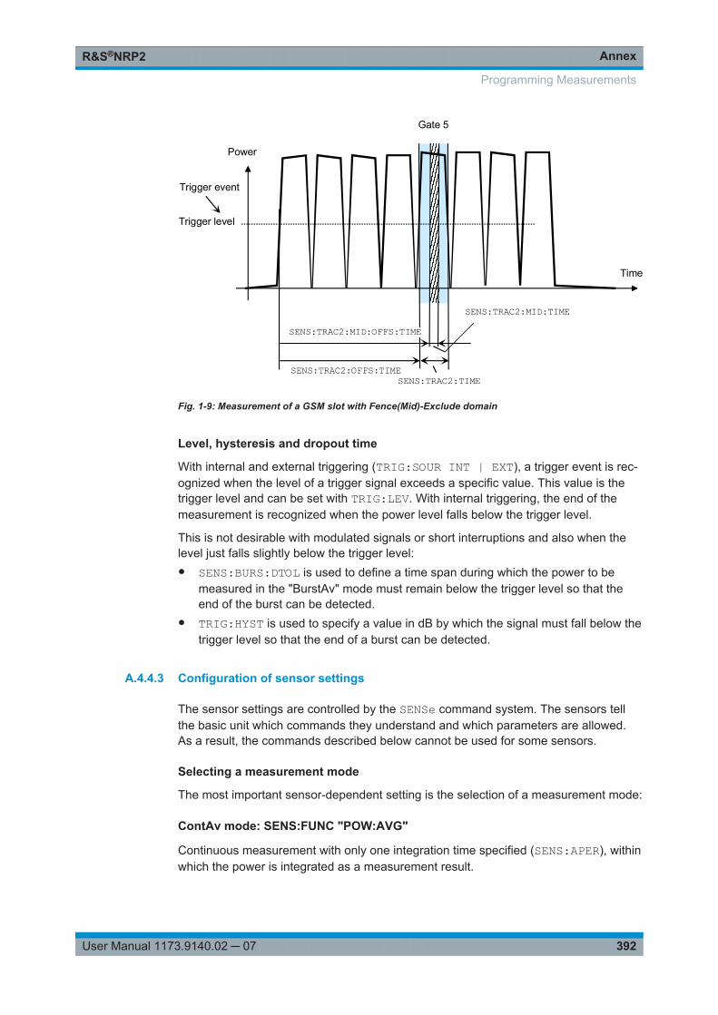
AnnexR&S®NRP2
392User Manual 1173.9140.02 ─ 07
Trigger level
Power
Time
Trigger event
SENS:TRAC2:OFFS:TIMESENS:TRAC2:TIME
Gate 5
SENS:TRAC2:MID:TIME
SENS:TRAC2:MID:OFFS:TIME
Fig. 1-9: Measurement of a GSM slot with Fence(Mid)-Exclude domain
Level, hysteresis and dropout time
With internal and external triggering (TRIG:SOUR INT | EXT), a trigger event is rec-ognized when the level of a trigger signal exceeds a specific value. This value is thetrigger level and can be set with TRIG:LEV. With internal triggering, the end of themeasurement is recognized when the power level falls below the trigger level.
This is not desirable with modulated signals or short interruptions and also when thelevel just falls slightly below the trigger level:● SENS:BURS:DTOL is used to define a time span during which the power to be
measured in the "BurstAv" mode must remain below the trigger level so that theend of the burst can be detected.
● TRIG:HYST is used to specify a value in dB by which the signal must fall below thetrigger level so that the end of a burst can be detected.
A.4.4.3 Configuration of sensor settings
The sensor settings are controlled by the SENSe command system. The sensors tellthe basic unit which commands they understand and which parameters are allowed.As a result, the commands described below cannot be used for some sensors.
Selecting a measurement mode
The most important sensor-dependent setting is the selection of a measurement mode:
ContAv mode: SENS:FUNC "POW:AVG"
Continuous measurement with only one integration time specified (SENS:APER), withinwhich the power is integrated as a measurement result.
Programming Measurements
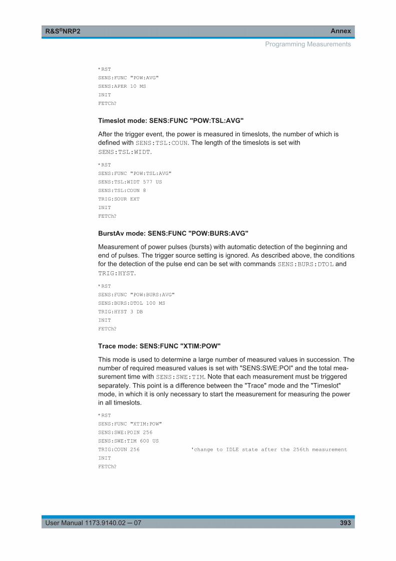
AnnexR&S®NRP2
393User Manual 1173.9140.02 ─ 07
*RSTSENS:FUNC "POW:AVG"SENS:APER 10 MS INITFETCh?
Timeslot mode: SENS:FUNC "POW:TSL:AVG"
After the trigger event, the power is measured in timeslots, the number of which isdefined with SENS:TSL:COUN. The length of the timeslots is set withSENS:TSL:WIDT.
*RSTSENS:FUNC "POW:TSL:AVG"SENS:TSL:WIDT 577 USSENS:TSL:COUN 8TRIG:SOUR EXTINITFETCh?
BurstAv mode: SENS:FUNC "POW:BURS:AVG"
Measurement of power pulses (bursts) with automatic detection of the beginning andend of pulses. The trigger source setting is ignored. As described above, the conditionsfor the detection of the pulse end can be set with commands SENS:BURS:DTOL andTRIG:HYST.
*RSTSENS:FUNC "POW:BURS:AVG"SENS:BURS:DTOL 100 MSTRIG:HYST 3 DBINITFETCh?
Trace mode: SENS:FUNC "XTIM:POW"
This mode is used to determine a large number of measured values in succession. Thenumber of required measured values is set with "SENS:SWE:POI" and the total mea-surement time with SENS:SWE:TIM. Note that each measurement must be triggeredseparately. This point is a difference between the "Trace" mode and the "Timeslot"mode, in which it is only necessary to start the measurement for measuring the powerin all timeslots.
*RSTSENS:FUNC "XTIM:POW"SENS:SWE:POIN 256SENS:SWE:TIM 600 USTRIG:COUN 256 'change to IDLE state after the 256th measurementINITFETCh?
Programming Measurements
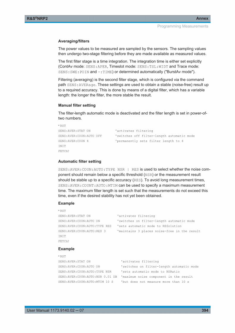
AnnexR&S®NRP2
394User Manual 1173.9140.02 ─ 07
Averaging/filters
The power values to be measured are sampled by the sensors. The sampling valuesthen undergo two-stage filtering before they are made available as measured values.
The first filter stage is a time integration. The integration time is either set explicitly(ContAv mode: SENS:APER, Timeslot mode: SENS:TSL:WIDT and Trace mode:SENS:SWE:POIN and -:TIME) or determined automatically ("BurstAv mode").
Filtering (averaging) is the second filter stage, which is configured via the commandpath SENS:AVERage. These settings are used to obtain a stable (noise-free) result upto a required accuracy. This is done by means of a digital filter, which has a variablelength: the longer the filter, the more stable the result.
Manual filter setting
The filter-length automatic mode is deactivated and the filter length is set in power-of-two numbers.
*RSTSENS:AVER:STAT ON 'activates filteringSENS:AVER:COUN:AUTO OFF 'switches off filter-length automatic modeSENS:AVER:COUN 4 'permanently sets filter length to 4INITFETCh?
Automatic filter setting
SENS:AVER:COUN:AUTO:TYPE NSR | RES is used to select whether the noise com-ponent should remain below a specific threshold (NSR) or the measurement resultshould be stable up to a specific accuracy (RES). To avoid long measurement times,SENS:AVER:COUNT:AUTO:MTIM can be used to specify a maximum measurementtime. The maximum filter length is set such that the measurements do not exceed thistime, even if the desired stability has not yet been obtained.
Example
*RSTSENS:AVER:STAT ON 'activates filteringSENS:AVER:COUN:AUTO ON 'switches on filter-length automatic modeSENS:AVER:COUN:AUTO:TYPE RES 'sets automatic mode to RESolutionSENS:AVER:COUN:AUTO:RES 3 'maintains 3 places noise-free in the resultINITFETCh?
Example
*RSTSENS:AVER:STAT ON 'activates filteringSENS:AVER:COUN:AUTO ON 'switches on filter-length automatic modeSENS:AVER:COUN:AUTO:TYPE NSR 'sets automatic mode to NSRatioSENS:AVER:COUN:AUTO:NSR 0.01 DB 'maximum noise component in the resultSENS:AVER:COUN:AUTO:MTIM 10 S 'but does not measure more than 10 s
Programming Measurements

AnnexR&S®NRP2
395User Manual 1173.9140.02 ─ 07
INITFETCh?
All intermediate pushed values delivered by the first filter stage are stored in the filter.The earliest measured value is ousted out of the filter, since the filter has only a limitedlength. SENS:AVER:TCON MOV | REP is used to set when the filter algorithm is to beapplied to the filter. With the setting MOVing, a new measure value is calculated foreach new intermediate measured value. This is the default setting in the LOCAL mode.SENS:AVER:TCON REPeat is set in the REMOTE mode. In this particular case, newmeasured values are calculated when all intermediate measured values have beenreplaced by new ones.
Changing from SENS:AVER:TCON MOV to REP in the LOCAL-REMOTE transition cau-ses the update rate of measured values to be reduced, since the filter must be com-pletely filled for each new measured value.
Measured-value corrections
The R&S NRP2 offers different options for correcting measured values in the instru-ment. These options all require an existing knowledge of the test setup or the timestructure of the signal. Offsets in the result can be corrected globally and depending onthe frequency, and it is possible to consider the duty cycle of a signal and the influenceof the complex reflection coefficient (Γ) of the power source.
Global offset correction
All measured values are multiplied by a correction factor (logarithmically added).
*RSTSENS:CORR:OFFS:STAT ON 'global offset correction ONSENS:CORR:OFFS 20 DB 'corrects result by +20 dBINITFETCh?
Frequency-dependent offset correction
Two-column tables can be entered in which frequencies and correction values can bestored. A frequency-dependent correction value is determined by linear interpolation inthe units Hz and dB using the signal frequency (defined with SENS:FREQ). The interpo-lated correction value can be queried with SENS:FDOF? for checking purposes.
Example
*RSTMEM:TABL:MOVE "Table 1" "Splitter" 'renames first tableMEM:TABL:SEL "Splitter" 'selects tableMEM:TABL:CLEar 'deletes selected tableMEM:TABL:FREQ 0,1e4,5e4,1e5,1e9 'interpolation points on the frequency axisMEM:TABL:GAIN 3.1,3.1,3.0,2.9,2.9 'associated offset valuesSENS:FREQ 900 MHZ 'signal frequencySENS:CORR:FDOT:STAT ON 'activates frequency-dependent offset correctionSENS:CORR:FDOT "Splitter" 'selects an offset table
Programming Measurements
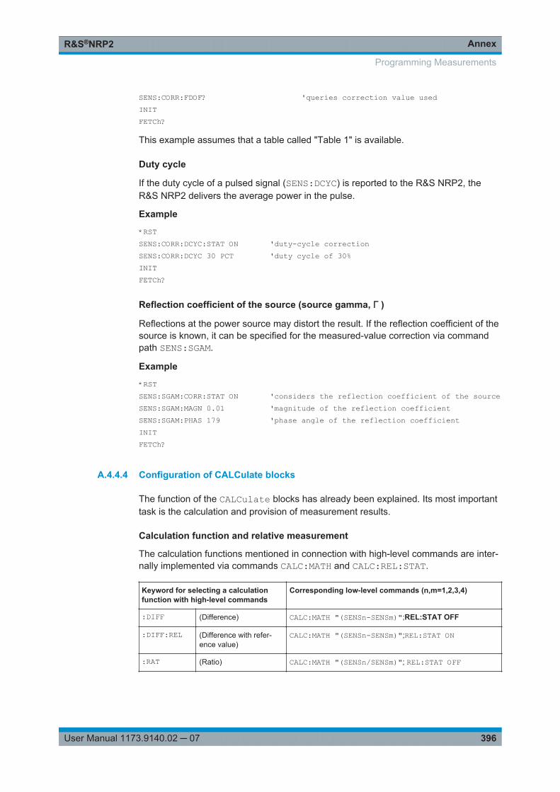
AnnexR&S®NRP2
396User Manual 1173.9140.02 ─ 07
SENS:CORR:FDOF? 'queries correction value usedINITFETCh?
This example assumes that a table called "Table 1" is available.
Duty cycle
If the duty cycle of a pulsed signal (SENS:DCYC) is reported to the R&S NRP2, theR&S NRP2 delivers the average power in the pulse.
Example
*RSTSENS:CORR:DCYC:STAT ON 'duty-cycle correctionSENS:CORR:DCYC 30 PCT 'duty cycle of 30%INITFETCh?
Reflection coefficient of the source (source gamma, Γ )
Reflections at the power source may distort the result. If the reflection coefficient of thesource is known, it can be specified for the measured-value correction via commandpath SENS:SGAM.
Example
*RSTSENS:SGAM:CORR:STAT ON 'considers the reflection coefficient of the sourceSENS:SGAM:MAGN 0.01 'magnitude of the reflection coefficientSENS:SGAM:PHAS 179 'phase angle of the reflection coefficient INITFETCh?
A.4.4.4 Configuration of CALCulate blocks
The function of the CALCulate blocks has already been explained. Its most importanttask is the calculation and provision of measurement results.
Calculation function and relative measurement
The calculation functions mentioned in connection with high-level commands are inter-nally implemented via commands CALC:MATH and CALC:REL:STAT.
Keyword for selecting a calculationfunction with high-level commands
Corresponding low-level commands (n,m=1,2,3,4)
:DIFF (Difference) CALC:MATH "(SENSn-SENSm)";REL:STAT OFF
:DIFF:REL (Difference with refer-ence value)
CALC:MATH "(SENSn-SENSm)";REL:STAT ON
:RAT (Ratio) CALC:MATH "(SENSn/SENSm)"; REL:STAT OFF
Programming Measurements
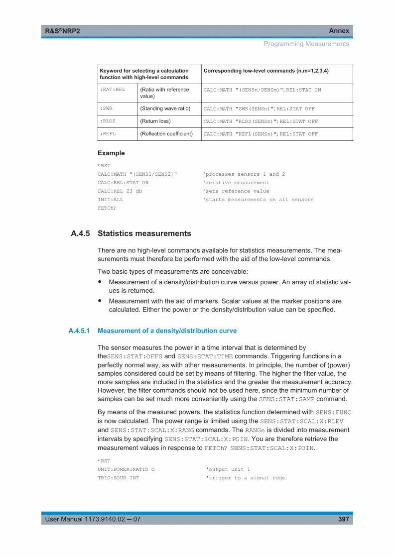
AnnexR&S®NRP2
397User Manual 1173.9140.02 ─ 07
Keyword for selecting a calculationfunction with high-level commands
Corresponding low-level commands (n,m=1,2,3,4)
:RAT:REL (Ratio with referencevalue)
CALC:MATH "(SENSn/SENSm)"; REL:STAT ON
:SWR (Standing wave ratio) CALC:MATH "SWR(SENSn)"; REL:STAT OFF
:RLOS (Return loss) CALC:MATH "RLOS(SENSn)"; REL:STAT OFF
:REFL (Reflection coefficient) CALC:MATH "REFL(SENSn)"; REL:STAT OFF
Example
*RSTCALC:MATH "(SENS1/SENS2)" 'processes sensors 1 and 2CALC:REL:STAT ON 'relative measurementCALC:REL 23 dB 'sets reference value INIT:ALL 'starts measurements on all sensorsFETCh?
A.4.5 Statistics measurements
There are no high-level commands available for statistics measurements. The mea-surements must therefore be performed with the aid of the low-level commands.
Two basic types of measurements are conceivable:● Measurement of a density/distribution curve versus power. An array of statistic val-
ues is returned.● Measurement with the aid of markers. Scalar values at the marker positions are
calculated. Either the power or the density/distribution value can be specified.
A.4.5.1 Measurement of a density/distribution curve
The sensor measures the power in a time interval that is determined bytheSENS:STAT:OFFS and SENS:STAT:TIME commands. Triggering functions in aperfectly normal way, as with other measurements. In principle, the number of (power)samples considered could be set by means of filtering. The higher the filter value, themore samples are included in the statistics and the greater the measurement accuracy.However, the filter commands should not be used here, since the minimum number ofsamples can be set much more conveniently using the SENS:STAT:SAMP command.
By means of the measured powers, the statistics function determined with SENS:FUNCis now calculated. The power range is limited using the SENS:STAT:SCAL:X:RLEVand SENS:STAT:SCAL:X:RANG commands. The RANGe is divided into measurementintervals by specifying SENS:STAT:SCAL:X:POIN. You are therefore retrieve themeasurement values in response to FETCh? SENS:STAT:SCAL:X:POIN.
*RSTUNIT:POWER:RATIO O 'output unit 1TRIG:SOUR INT 'trigger to a signal edge
Programming Measurements
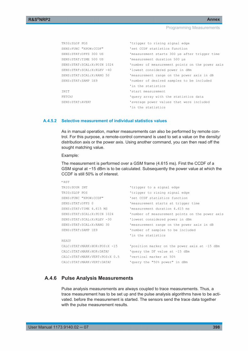
AnnexR&S®NRP2
398User Manual 1173.9140.02 ─ 07
TRIG:SLOP POS 'trigger to rising signal edgeSENS:FUNC "XPOW:CCDF" 'set CCDF statistics functionSENS:STAT:OFFS 300 US 'measurement starts 300 µs after trigger timeSENS:STAT:TIME 500 US 'measurement duration 500 µsSENS:STAT:SCAL:X:POIN 1024 'number of measurement points on the power axisSENS:STAT:SCAL:X:RLEV -40 'lowest considered power in dBmSENS:STAT:SCAL:X:RANG 50 'measurement range on the power axis in dBSENS:STAT:SAMP 1E9 'number of desired samples to be included 'in the statisticsINIT 'start measurementFETCh? 'query array with the statistics dataSENS:STAT:AVER? 'average power values that were included 'in the statistics
A.4.5.2 Selective measurement of individual statistics values
As in manual operation, marker measurements can also be performed by remote con-trol. For this purpose, a remote-control command is used to set a value on the density/distribution axis or the power axis. Using another command, you can then read off thesought matching value.
Example:
The measurement is performed over a GSM frame (4.615 ms). First the CCDF of aGSM signal at −15 dBm is to be calculated. Subsequently the power value at which theCCDF is still 50% is of interest.
*RSTTRIG:SOUR INT 'trigger to a signal edgeTRIG:SLOP POS 'trigger to rising signal edgeSENS:FUNC "XPOW:CCDF" 'set CCDF statistics functionSENS:STAT:OFFS 0 'measurement starts at trigger timeSENS:STAT:TIME 4.615 MS 'measurement duration 4.615 msSENS:STAT:SCAL:X:POIN 1024 'number of measurement points on the power axisSENS:STAT:SCAL:X:RLEV -30 'lowest considered power in dBmSENS:STAT:SCAL:X:RANG 30 'measurement range on the power axis in dBSENS:STAT:SAMP 1E9 'number of samples to be included 'in the statisticsREAD? CALC:STAT:MARK:HOR:POS:X -15 'position marker on the power axis at −15 dBmCALC:STAT:MARK:HOR:DATA? 'query the DF value at −15 dBmCALC:STAT:MARK:VERT:POS:X 0.5 'vertical marker at 50%CALC:STAT:MARK:VERT:DATA? 'query the "50% power" in dBm
A.4.6 Pulse Analysis Measurements
Pulse analysis measurements are always coupled to trace measurements. Thus, atrace measurement has to be set up and the pulse analysis algorithms have to be acti-vated. before the measurement is started. The sensors send the trace data togetherwith the pulse measurement results.
Programming Measurements
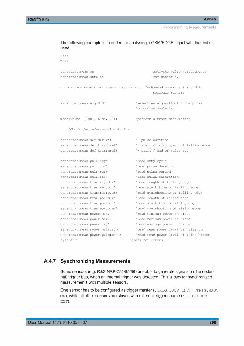
AnnexR&S®NRP2
399User Manual 1173.9140.02 ─ 07
The following example is intended for analysing a GSM/EDGE signal with the first slotused.
*rst*cls
sens:trac:meas on 'activate pulse measurementssens:trac:meas:auto on 'for sensor A.
sense:trace:meas:tran:esam:auto:state on 'enhanced accuracy for stable 'periodic signals
sens:trac:meas:alg HIST 'select an algorithm for the pulse 'detection analysis
meas:xtime? (100), 6 ms, (@1) 'perform a trace measurement
'Check the reference levels for
sens:trac:meas:def:dur:ref? '- pulse durationsens:trac:meas:def:tran:lref? '- start of rising/end of falling edgesens:trac:meas:def:tran:href? '- start / end of pulse top
sens:trac:meas:puls:dcyc? 'read duty cyclesens:trac:meas:puls:dur? 'read pulse durationsens:trac:meas:puls:per? 'read pulse periodsens:trac:meas:puls:sep? 'read pulse separationsens:trac:meas:tran:neg:dur? 'read length of falling edgesens:trac:meas:tran:neg:occ? 'read start time of falling edgesens:trac:meas:tran:neg:over? 'read overshooting of falling edgesens:trac:meas:tran:pos:dur? 'read length of rising edgesens:trac:meas:tran:pos:occ? 'read start time of rising edgesens:trac:meas:tran:pos:over? 'read overshooting of rising edgesens:trac:meas:power:min? 'read minimum power in tracesens:trac:meas:power:max? 'read maximum power in tracesens:trac:meas:power:avg? 'read average power in tracesens:trac:meas:power:puls:top? 'read mean power level of pulse topsens:trac:meas:power:puls:base? 'read mean power level of pulse bottomsyst:err? 'check for errors
A.4.7 Synchronizing Measurements
Some sensors (e.g. R&S NRP-Z81/85/86) are able to generate signals on the (exter-nal) trigger bus, when an internal trigger was detected. This allows for synchronizedmeasurements with multiple sensors.
One sensor has to be configured as trigger master (:TRIG:SOUR INT; :TRIG:MASTON), while all other sensors are slaves with external trigger source (:TRIG:SOUREXT).
Programming Measurements
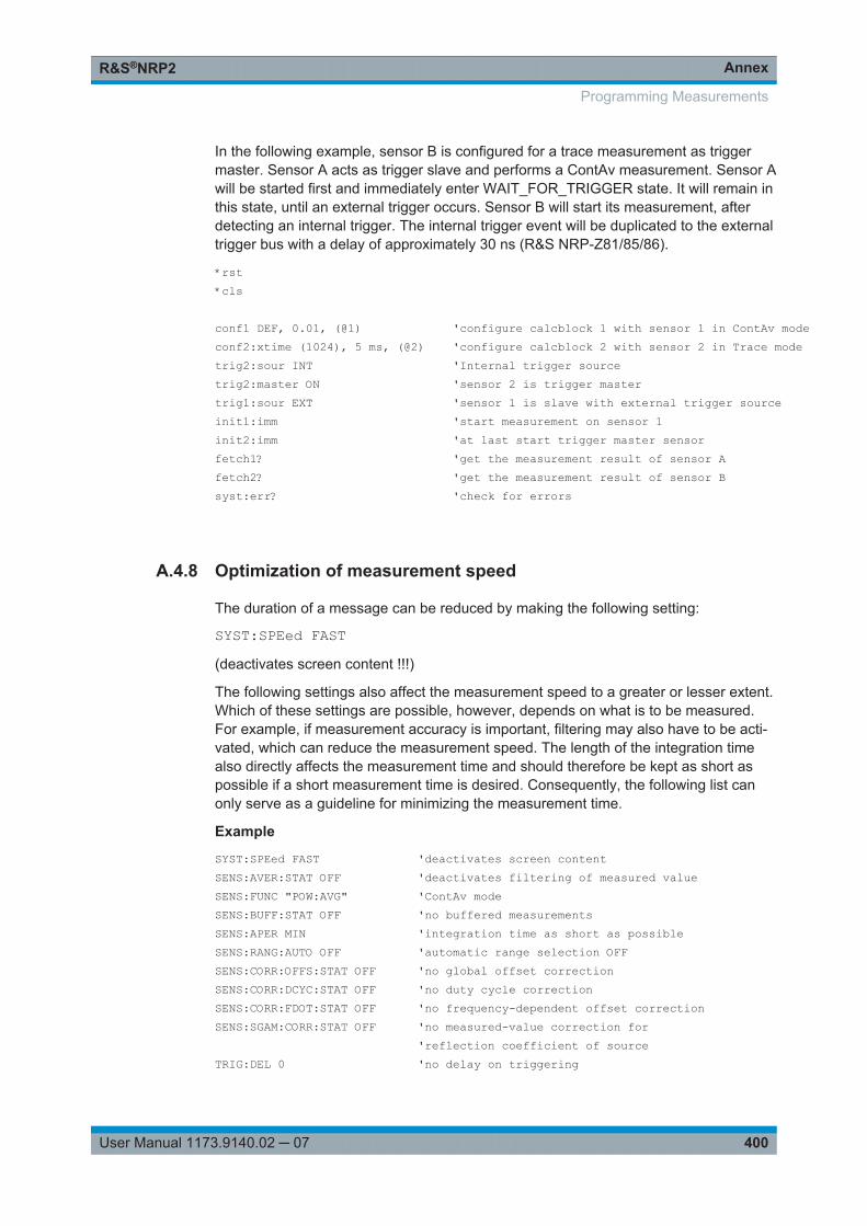
AnnexR&S®NRP2
400User Manual 1173.9140.02 ─ 07
In the following example, sensor B is configured for a trace measurement as triggermaster. Sensor A acts as trigger slave and performs a ContAv measurement. Sensor Awill be started first and immediately enter WAIT_FOR_TRIGGER state. It will remain inthis state, until an external trigger occurs. Sensor B will start its measurement, afterdetecting an internal trigger. The internal trigger event will be duplicated to the externaltrigger bus with a delay of approximately 30 ns (R&S NRP-Z81/85/86).
*rst *cls
conf1 DEF, 0.01, (@1) 'configure calcblock 1 with sensor 1 in ContAv modeconf2:xtime (1024), 5 ms, (@2) 'configure calcblock 2 with sensor 2 in Trace modetrig2:sour INT 'Internal trigger sourcetrig2:master ON 'sensor 2 is trigger mastertrig1:sour EXT 'sensor 1 is slave with external trigger sourceinit1:imm 'start measurement on sensor 1init2:imm 'at last start trigger master sensorfetch1? 'get the measurement result of sensor Afetch2? 'get the measurement result of sensor Bsyst:err? 'check for errors
A.4.8 Optimization of measurement speed
The duration of a message can be reduced by making the following setting:
SYST:SPEed FAST(deactivates screen content !!!)
The following settings also affect the measurement speed to a greater or lesser extent.Which of these settings are possible, however, depends on what is to be measured.For example, if measurement accuracy is important, filtering may also have to be acti-vated, which can reduce the measurement speed. The length of the integration timealso directly affects the measurement time and should therefore be kept as short aspossible if a short measurement time is desired. Consequently, the following list canonly serve as a guideline for minimizing the measurement time.
Example
SYST:SPEed FAST 'deactivates screen contentSENS:AVER:STAT OFF 'deactivates filtering of measured valueSENS:FUNC "POW:AVG" 'ContAv modeSENS:BUFF:STAT OFF 'no buffered measurementsSENS:APER MIN 'integration time as short as possibleSENS:RANG:AUTO OFF 'automatic range selection OFFSENS:CORR:OFFS:STAT OFF 'no global offset correctionSENS:CORR:DCYC:STAT OFF 'no duty cycle correctionSENS:CORR:FDOT:STAT OFF 'no frequency-dependent offset correctionSENS:SGAM:CORR:STAT OFF 'no measured-value correction for 'reflection coefficient of sourceTRIG:DEL 0 'no delay on triggering
Programming Measurements
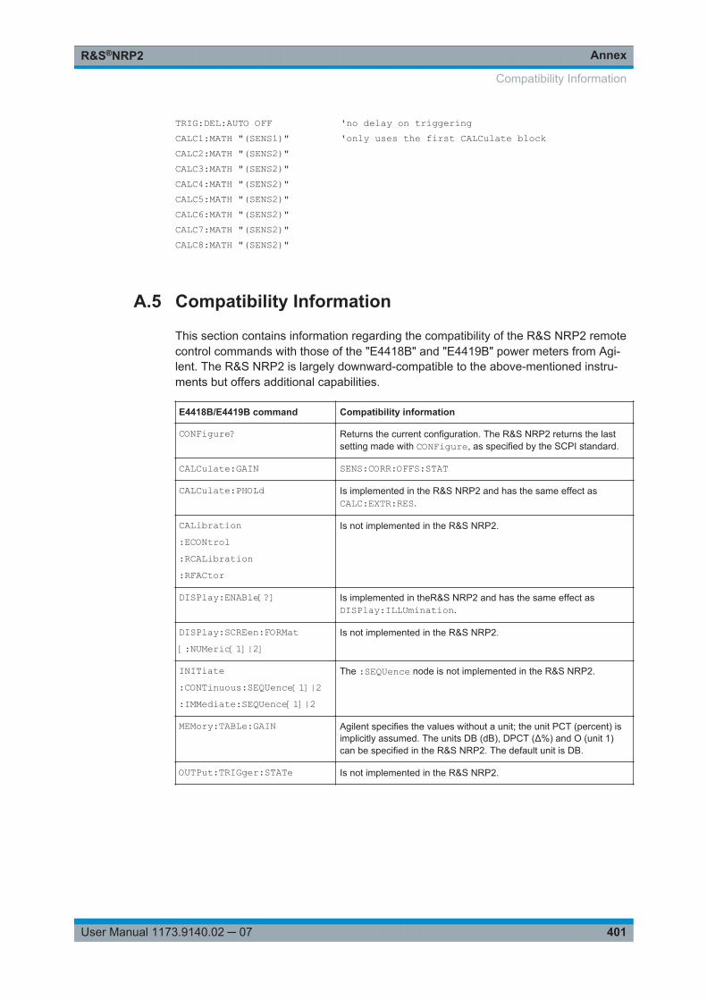
AnnexR&S®NRP2
401User Manual 1173.9140.02 ─ 07
TRIG:DEL:AUTO OFF 'no delay on triggeringCALC1:MATH "(SENS1)" 'only uses the first CALCulate blockCALC2:MATH "(SENS2)"CALC3:MATH "(SENS2)"CALC4:MATH "(SENS2)"CALC5:MATH "(SENS2)"CALC6:MATH "(SENS2)"CALC7:MATH "(SENS2)"CALC8:MATH "(SENS2)"
A.5 Compatibility Information
This section contains information regarding the compatibility of the R&S NRP2 remotecontrol commands with those of the "E4418B" and "E4419B" power meters from Agi-lent. The R&S NRP2 is largely downward-compatible to the above-mentioned instru-ments but offers additional capabilities.
E4418B/E4419B command Compatibility information
CONFigure? Returns the current configuration. The R&S NRP2 returns the lastsetting made with CONFigure, as specified by the SCPI standard.
CALCulate:GAIN SENS:CORR:OFFS:STAT
CALCulate:PHOLd Is implemented in the R&S NRP2 and has the same effect asCALC:EXTR:RES.
CALibration:ECONtrol:RCALibration:RFACtor
Is not implemented in the R&S NRP2.
DISPlay:ENABle[?] Is implemented in theR&S NRP2 and has the same effect asDISPlay:ILLUmination.
DISPlay:SCREen:FORMat[:NUMeric[1]|2]
Is not implemented in the R&S NRP2.
INITiate:CONTinuous:SEQUence[1]|2:IMMediate:SEQUence[1]|2
The :SEQUence node is not implemented in the R&S NRP2.
MEMory:TABLe:GAIN Agilent specifies the values without a unit; the unit PCT (percent) isimplicitly assumed. The units DB (dB), DPCT (Δ%) and O (unit 1)can be specified in the R&S NRP2. The default unit is DB.
OUTPut:TRIGger:STATe Is not implemented in the R&S NRP2.
Compatibility Information
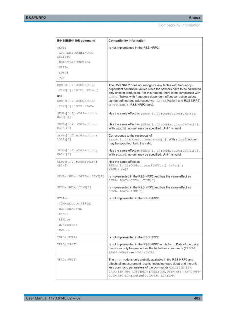
AnnexR&S®NRP2
402User Manual 1173.9140.02 ─ 07
E4418B/E4419B command Compatibility information
SENSe:AVERage:COUNt:AUTO:SDETect:DETector:FUNCtion:MRATe:SPEed:V2P
Is not implemented in the R&S NRP2.
SENSe[1|2]:CORRection:CSET[1]|CSET2[:SELect]and
SENSe[1|2]:CORRection:CSET[1]|CSET2:STATe
The R&S NRP2 does not recognize any tables with frequency-dependent calibration values since the sensors have to be calibratedonly once in production. For this reason, there is no compliance withCSET1. Tables with frequency-dependent offset correction valuescan be defined and addressed via :CSET2 (Agilent and R&S NRP2)or :FDOTable (R&S NRP2 only).
SENSe[1|2]:CORRection:GAIN[1]?
Has the same effect as SENSe[1..2]:CORRection:CFACtor?
SENSe[1|2]:CORRection:GAIN2[?]
Has the same effect as SENSe[1..2]:CORRection:OFFSet[?].With :GAIN2, no unit may be specified. Unit 1 is valid.
SENSe[1|2]:CORRection:LOSS2[?]
Corresponds to the reciprocal ofSENSe[1..2]:CORRection:OFFSet[?]. With :LOSS2, no unitmay be specified. Unit 1 is valid.
SENSe[1|2]:CORRection:GAIN3[?]
Has the same effect as SENSe[1..2]:CORRection:DCYCle[?].With :GAIN3, no unit may be specified. Unit 1 is valid.
SENSe[1|2]:CORRection:GAIN4?
Has the same effect asSENSe[1..2]:CORRection:FDOFfset[:INPut][:MAGNitude]?
SENSe:SWEep:OFFSet:TIME[?] Is implemented in the R&S NRP2 and has the same effect asSENSe:TGATe:OFFSet:TIME[?]
SENSe:SWEep:TIME[?] Is implemented in the R&S NRP2 and has the same effect asSENSe:TGATe:TIME[?]
SYSTem:COMMunicate:SERial:HELP:HEADers?:LOCal:REMote:RINTerface:RWLock
Is not implemented in the R&S NRP2.
TRACe:STATe Is not implemented in the R&S NRP2.
TRACe:DATA? Is not implemented in the R&S NRP2 in this form. Data of the tracemode can only be queried via the high-level commands (FETCh?,READ?, MEAS?) and CALC:DATA?.
TRACe:UNIT? The UNIT node is only globally available in the R&S NRP2 andaffects all measurement results (including trace data) and the unit-less command parameters of the commands CALC:LIM:LOW,CALC:LIM:UPP, DISP:MET|:ANAL:LOW, DISP:MET|:ANAL:UPP,OUTP:REC:LIM:LOW and OUTP:REC:LIM:UPP.
Compatibility Information
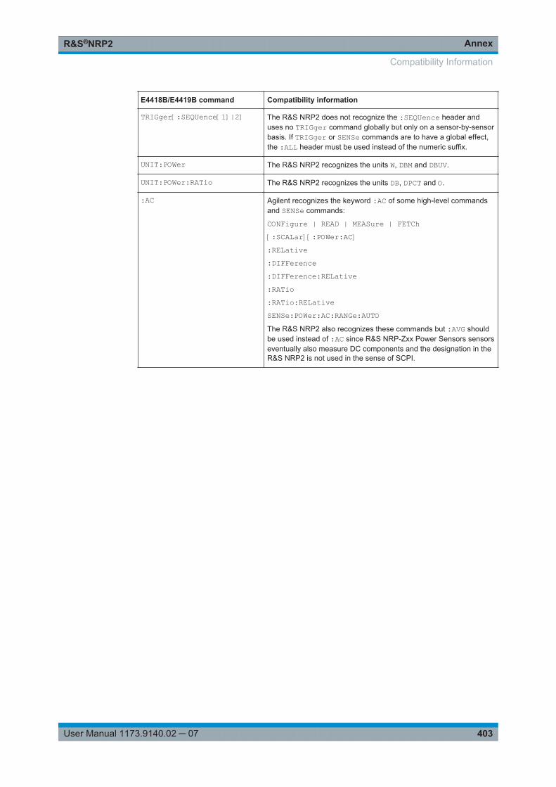
AnnexR&S®NRP2
403User Manual 1173.9140.02 ─ 07
E4418B/E4419B command Compatibility information
TRIGger[:SEQUence[1]|2] The R&S NRP2 does not recognize the :SEQUence header anduses no TRIGger command globally but only on a sensor-by-sensorbasis. If TRIGger or SENSe commands are to have a global effect,the :ALL header must be used instead of the numeric suffix.
UNIT:POWer The R&S NRP2 recognizes the units W, DBM and DBUV.
UNIT:POWer:RATio The R&S NRP2 recognizes the units DB, DPCT and O.
:AC Agilent recognizes the keyword :AC of some high-level commandsand SENSe commands:
CONFigure | READ | MEASure | FETCh[:SCALar][:POWer:AC]:RELative:DIFFerence:DIFFerence:RELative:RATio:RATio:RELativeSENSe:POWer:AC:RANGe:AUTOThe R&S NRP2 also recognizes these commands but :AVG shouldbe used instead of :AC since R&S NRP-Zxx Power Sensors sensorseventually also measure DC components and the designation in theR&S NRP2 is not used in the sense of SCPI.
Compatibility Information

AnnexR&S®NRP2
404User Manual 1173.9140.02 ─ 07
Compatibility Information
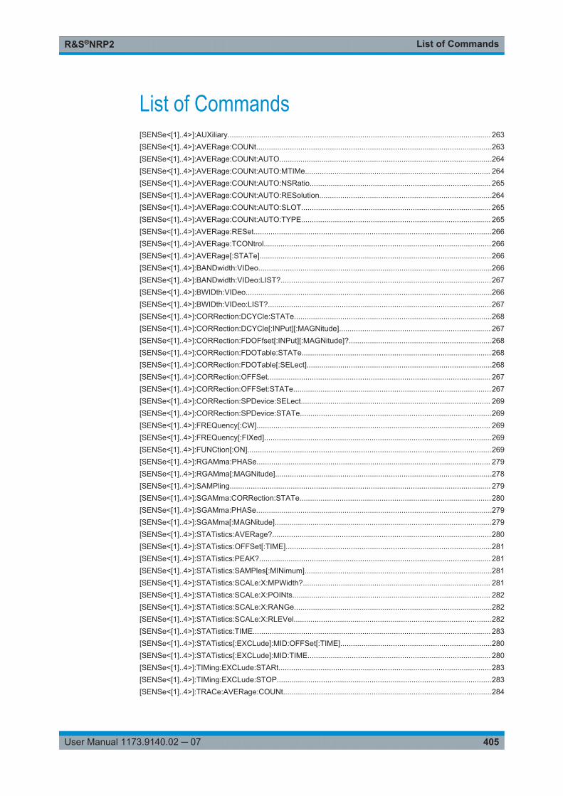
List of CommandsR&S®NRP2
405User Manual 1173.9140.02 ─ 07
List of Commands[SENSe<[1]..4>]:AUXiliary............................................................................................................................. 263[SENSe<[1]..4>]:AVERage:COUNt................................................................................................................263[SENSe<[1]..4>]:AVERage:COUNt:AUTO.....................................................................................................264[SENSe<[1]..4>]:AVERage:COUNt:AUTO:MTIMe........................................................................................ 264[SENSe<[1]..4>]:AVERage:COUNt:AUTO:NSRatio...................................................................................... 265[SENSe<[1]..4>]:AVERage:COUNt:AUTO:RESolution..................................................................................264[SENSe<[1]..4>]:AVERage:COUNt:AUTO:SLOT.......................................................................................... 265[SENSe<[1]..4>]:AVERage:COUNt:AUTO:TYPE.......................................................................................... 265[SENSe<[1]..4>]:AVERage:RESet.................................................................................................................266[SENSe<[1]..4>]:AVERage:TCONtrol............................................................................................................266[SENSe<[1]..4>]:AVERage[:STATe]..............................................................................................................266[SENSe<[1]..4>]:BANDwidth:VIDeo...............................................................................................................266[SENSe<[1]..4>]:BANDwidth:VIDeo:LIST?....................................................................................................267[SENSe<[1]..4>]:BWIDth:VIDeo.....................................................................................................................266[SENSe<[1]..4>]:BWIDth:VIDeo:LIST?..........................................................................................................267[SENSe<[1]..4>]:CORRection:DCYCle:STATe..............................................................................................268[SENSe<[1]..4>]:CORRection:DCYCle[:INPut][:MAGNitude]........................................................................ 267[SENSe<[1]..4>]:CORRection:FDOFfset[:INPut][:MAGNitude]?....................................................................268[SENSe<[1]..4>]:CORRection:FDOTable:STATe..........................................................................................268[SENSe<[1]..4>]:CORRection:FDOTable[:SELect]........................................................................................268[SENSe<[1]..4>]:CORRection:OFFSet.......................................................................................................... 267[SENSe<[1]..4>]:CORRection:OFFSet:STATe..............................................................................................267[SENSe<[1]..4>]:CORRection:SPDevice:SELect.......................................................................................... 269[SENSe<[1]..4>]:CORRection:SPDevice:STATe...........................................................................................269[SENSe<[1]..4>]:FREQuency[:CW]............................................................................................................... 269[SENSe<[1]..4>]:FREQuency[:FIXed]............................................................................................................269[SENSe<[1]..4>]:FUNCtion[:ON]....................................................................................................................269[SENSe<[1]..4>]:RGAMma:PHASe............................................................................................................... 279[SENSe<[1]..4>]:RGAMma[:MAGNitude].......................................................................................................278[SENSe<[1]..4>]:SAMPling............................................................................................................................ 279[SENSe<[1]..4>]:SGAMma:CORRection:STATe...........................................................................................280[SENSe<[1]..4>]:SGAMma:PHASe................................................................................................................279[SENSe<[1]..4>]:SGAMma[:MAGNitude].......................................................................................................279[SENSe<[1]..4>]:STATistics:AVERage?........................................................................................................280[SENSe<[1]..4>]:STATistics:OFFSet[:TIME]..................................................................................................281[SENSe<[1]..4>]:STATistics:PEAK?.............................................................................................................. 281[SENSe<[1]..4>]:STATistics:SAMPles[:MINimum].........................................................................................281[SENSe<[1]..4>]:STATistics:SCALe:X:MPWidth?......................................................................................... 281[SENSe<[1]..4>]:STATistics:SCALe:X:POINts.............................................................................................. 282[SENSe<[1]..4>]:STATistics:SCALe:X:RANGe..............................................................................................282[SENSe<[1]..4>]:STATistics:SCALe:X:RLEVel..............................................................................................282[SENSe<[1]..4>]:STATistics:TIME................................................................................................................. 283[SENSe<[1]..4>]:STATistics[:EXCLude]:MID:OFFSet[:TIME]........................................................................280[SENSe<[1]..4>]:STATistics[:EXCLude]:MID:TIME....................................................................................... 280[SENSe<[1]..4>]:TIMing:EXCLude:STARt.....................................................................................................283[SENSe<[1]..4>]:TIMing:EXCLude:STOP......................................................................................................283[SENSe<[1]..4>]:TRACe:AVERage:COUNt...................................................................................................284
List of CommandsR&S®NRP2
406User Manual 1173.9140.02 ─ 07
[SENSe<[1]..4>]:TRACe:AVERage:COUNt:AUTO........................................................................................284[SENSe<[1]..4>]:TRACe:AVERage:COUNt:AUTO:MTIMe............................................................................285[SENSe<[1]..4>]:TRACe:AVERage:COUNt:AUTO:NSRatio......................................................................... 286[SENSe<[1]..4>]:TRACe:AVERage:COUNt:AUTO:POINt.............................................................................286[SENSe<[1]..4>]:TRACe:AVERage:COUNt:AUTO:RESolution.....................................................................285[SENSe<[1]..4>]:TRACe:AVERage:COUNt:AUTO:TYPE............................................................................. 286[SENSe<[1]..4>]:TRACe:AVERage:TCONtrol............................................................................................... 287[SENSe<[1]..4>]:TRACe:AVERage[:STATe]................................................................................................. 284[SENSe<[1]..4>]:TRACe:MEASurement:ALGorithm......................................................................................287[SENSe<[1]..4>]:TRACe:MEASurement:AUTO[:STATe]...............................................................................287[SENSe<[1]..4>]:TRACe:MEASurement:DEFine:DURation:REFerence.......................................................288[SENSe<[1]..4>]:TRACe:MEASurement:DEFine:TRANsition:HREFerence..................................................288[SENSe<[1]..4>]:TRACe:MEASurement:DEFine:TRANsition:LREFerence.................................................. 288[SENSe<[1]..4>]:TRACe:MEASurement:POWer:AVG?................................................................................ 288[SENSe<[1]..4>]:TRACe:MEASurement:POWer:MAX?................................................................................ 289[SENSe<[1]..4>]:TRACe:MEASurement:POWer:MIN?................................................................................. 289[SENSe<[1]..4>]:TRACe:MEASurement:POWer:PULSe:BASE?..................................................................289[SENSe<[1]..4>]:TRACe:MEASurement:POWer:PULSe:TOP?.................................................................... 289[SENSe<[1]..4>]:TRACe:MEASurement:PULSe:DCYCle?........................................................................... 289[SENSe<[1]..4>]:TRACe:MEASurement:PULSe:DURation?.........................................................................289[SENSe<[1]..4>]:TRACe:MEASurement:PULSe:PERiod?............................................................................ 289[SENSe<[1]..4>]:TRACe:MEASurement:PULSe:SEParation?...................................................................... 290[SENSe<[1]..4>]:TRACe:MEASurement:TRANSition:ESAMpling:AUTO[:STATe]?......................................290[SENSe<[1]..4>]:TRACe:MEASurement:TRANSition:NEGative:DURation?.................................................290[SENSe<[1]..4>]:TRACe:MEASurement:TRANSition:NEGative:OCCurrence?............................................ 290[SENSe<[1]..4>]:TRACe:MEASurement:TRANSition:NEGative:OVERshoot?..............................................290[SENSe<[1]..4>]:TRACe:MEASurement:TRANSition:POSitive:DURation?.................................................. 291[SENSe<[1]..4>]:TRACe:MEASurement:TRANSition:POSitive:OCCurrence?..............................................291[SENSe<[1]..4>]:TRACe:MEASurement:TRANSition:POSitive:OVERshoot?...............................................291[SENSe<[1]..4>]:TRACe:MEASurement:TRANSition:SPERiod?.................................................................. 291[SENSe<[1]..4>]:TRACe:MEASurement[:STATe]..........................................................................................291[SENSe<[1]..4>]:TRACe:MID:OFFSet:TIME................................................................................................. 292[SENSe<[1]..4>]:TRACe:MID:TIME...............................................................................................................292[SENSe<[1]..4>]:TRACe:OFFSet:TIME.........................................................................................................292[SENSe<[1]..4>]:TRACe:POINts....................................................................................................................292[SENSe<[1]..4>]:TRACe:REALtime...............................................................................................................293[SENSe<[1]..4>]:TRACe:TIME.......................................................................................................................293[SENSe<[1]..4>][:POWer]:BURSt:DTOLerance.............................................................................................274[SENSe<[1]..4>][:POWer]:TGATe:SELect.....................................................................................................276[SENSe<[1]..4>][:POWer]:TGATe[:EXCLude]:MID[:STATe]......................................................................... 275[SENSe<[1]..4>][:POWer]:TGATe<[1]..4>:OFFSet:TIME.............................................................................. 275[SENSe<[1]..4>][:POWer]:TGATe<[1]..4>:TIME............................................................................................276[SENSe<[1]..4>][:POWer]:TGATe<[1]..4>[:EXCLude]:MID:OFFSet[:TIME] ................................................. 274[SENSe<[1]..4>][:POWer]:TGATe<[1]..4>[:EXCLude]:MID:TIME..................................................................275[SENSe<[1]..4>][:POWer]:TSLot:[AVG]:WIDTh.............................................................................................278[SENSe<[1]..4>][:POWer]:TSLot:COUNt.......................................................................................................277[SENSe<[1]..4>][:POWer]:TSLot[:EXCLude]:MID:OFFSet[:TIME]................................................................ 277[SENSe<[1]..4>][:POWer]:TSLot[:EXCLude]:MID:TIME................................................................................277[SENSe<[1]..4>][:POWer]:TSLot[:EXCLude]:MID[:STATe]........................................................................... 277[SENSe<[1]..4>][:POWer][:AVG]:APERture...................................................................................................272
List of CommandsR&S®NRP2
407User Manual 1173.9140.02 ─ 07
[SENSe<[1]..4>][:POWer][:AVG]:BUFFer:SIZE.............................................................................................272[SENSe<[1]..4>][:POWer][:AVG]:BUFFer:STATe..........................................................................................272[SENSe<[1]..4>][:POWer][:AVG]:RANGe...................................................................................................... 273[SENSe<[1]..4>][:POWer][:AVG]:RANGe:AUTO........................................................................................... 273[SENSe<[1]..4>][:POWer][:AVG]:RANGe:CLEVel.........................................................................................273[SENSe<[1]..4>][:POWer][:AVG]:SMOothing:STATe.................................................................................... 273*CLS...............................................................................................................................................................195*ESE.............................................................................................................................................................. 195*ESR?............................................................................................................................................................ 196*IDN?............................................................................................................................................................. 196*IST?..............................................................................................................................................................196*OPC..............................................................................................................................................................196*OPT?............................................................................................................................................................ 197*PRE.............................................................................................................................................................. 197*PSC.............................................................................................................................................................. 197*RCL.............................................................................................................................................................. 198*RST.............................................................................................................................................................. 198*SAV ............................................................................................................................................................. 204*SRE.............................................................................................................................................................. 204*STB?.............................................................................................................................................................205*TRG..............................................................................................................................................................205*TST?.............................................................................................................................................................205*WAI...............................................................................................................................................................205ABORt:ALL.................................................................................................................................................... 329ABORt<[1]..4>................................................................................................................................................329CALCulate<[1]..4>:STATistics:MARKer: HORIzontal:POSition[:X][:POWer] ................................................235CALCulate<[1]..4>:STATistics:MARKer:HORizontal:DATA?.........................................................................235CALCulate<[1]..4>:STATistics:MARKer:VERTical:DATA[:POWer]?............................................................. 235CALCulate<[1]..4>:STATistics:MARKer:VERTical:POSition[:Y]....................................................................235CALCulate<[1]..4>:STATistics:POWer:AVG:DATA?..................................................................................... 236CALCulate<[1]..8>:COUNt:DATA?................................................................................................................ 225CALCulate<[1]..8>:DATA?.............................................................................................................................225CALCulate<[1]..8>:EXTRemes:RESet...........................................................................................................226CALCulate<[1]..8>:FEED<[1]|2>....................................................................................................................226CALCulate<[1]..8>:LIMit:BEEP......................................................................................................................227CALCulate<[1]..8>:LIMit:CLEar:AUTO.......................................................................................................... 227CALCulate<[1]..8>:LIMit:CLEar[:IMMediate]..................................................................................................227CALCulate<[1]..8>:LIMit:FAIL?......................................................................................................................228CALCulate<[1]..8>:LIMit:FCOunt?.................................................................................................................228CALCulate<[1]..8>:LIMit:LOWer:STATe........................................................................................................229CALCulate<[1]..8>:LIMit:LOWer[:DATA]........................................................................................................228CALCulate<[1]..8>:LIMit:LOWer[:DATA]:POWer...........................................................................................229CALCulate<[1]..8>:LIMit:LOWer[:DATA]:RATio.............................................................................................229CALCulate<[1]..8>:LIMit:STATe.................................................................................................................... 229CALCulate<[1]..8>:LIMit:UPPer:STATe.........................................................................................................230CALCulate<[1]..8>:LIMit:UPPer[:DATA]........................................................................................................ 230CALCulate<[1]..8>:LIMit:UPPer[:DATA]:POWer............................................................................................230CALCulate<[1]..8>:LIMit:UPPer[:DATA]:RATio............................................................................................. 230CALCulate<[1]..8>:MATH[:EXPRession].......................................................................................................231CALCulate<[1]..8>:MATH[:EXPRession]:CATalog?......................................................................................232
List of CommandsR&S®NRP2
408User Manual 1173.9140.02 ─ 07
CALCulate<[1]..8>:MAXimum:DATA?........................................................................................................... 232CALCulate<[1]..8>:MEAN:DATA?................................................................................................................. 232CALCulate<[1]..8>:MINimum:DATA?............................................................................................................ 232CALCulate<[1]..8>:PTPeak:DATA?...............................................................................................................233CALCulate<[1]..8>:RELative:POWer[:MAGNitude]....................................................................................... 234CALCulate<[1]..8>:RELative:RATio[:MAGNitude]......................................................................................... 234CALCulate<[1]..8>:RELative:STATe..............................................................................................................234CALCulate<[1]..8>:RELative[:MAGNitude].................................................................................................... 233CALCulate<[1]..8>:RELative[:MAGNitude]:AUTO......................................................................................... 233CALCulate<[1]..8>:SDEViation:DATA?......................................................................................................... 234CALCulate<[1]..8>:TRACe:MARKer:XDELta?...............................................................................................236CALCulate<[1]..8>:TRACe:MARKer:YDELta?...............................................................................................236CALCulate<[1]..8>:TRACe:MARKer<[1]..2>:XPOSition................................................................................ 236CALCulate<[1]..8>:TRACe:MARKer<[1]..2>:YPOSition?.............................................................................. 237CALibration:ALL:ZERO:AUTO.......................................................................................................................237CALibration:ALL:ZERO:FAST:AUTO.............................................................................................................238CALibration<[1]..4>:DATA............................................................................................................................. 237CALibration<[1]..4>:ZERO:AUTO..................................................................................................................237CALibration<[1]..4>:ZERO:FAST:AUTO........................................................................................................238CONFigure<[1]..8>:ARRay[:POWer][:AVG]...................................................................................................218CONFigure<[1]..8>:ARRay[:POWer][:AVG]:DIFFerence...............................................................................218CONFigure<[1]..8>:ARRay[:POWer][:AVG]:DIFFerence:RELative............................................................... 218CONFigure<[1]..8>:ARRay[:POWer][:AVG]:RATio........................................................................................218CONFigure<[1]..8>:ARRay[:POWer][:AVG]:RATio:RELative........................................................................ 218CONFigure<[1]..8>:ARRay[:POWer][:AVG]:REFLection...............................................................................218CONFigure<[1]..8>:ARRay[:POWer][:AVG]:RELative................................................................................... 218CONFigure<[1]..8>:ARRay[:POWer][:AVG]:RLOSs...................................................................................... 218CONFigure<[1]..8>:ARRay[:POWer][:AVG]:SUM..........................................................................................218CONFigure<[1]..8>:ARRay[:POWer][:AVG]:SUM:RELative.......................................................................... 218CONFigure<[1]..8>:ARRay[:POWer][:AVG]:SWR......................................................................................... 218CONFigure<[1]..8>:STATistics:CCDF........................................................................................................... 219CONFigure<[1]..8>:STATistics:PDF.............................................................................................................. 219CONFigure<[1]..8>:XTIMe[:POWer].............................................................................................................. 218CONFigure<[1]..8>:XTIMe[:POWer]:RATio................................................................................................... 218CONFigure<[1]..8>[:SCALar][:POWer]:BURSt.............................................................................................. 218CONFigure<[1]..8>[:SCALar][:POWer]:BURSt:DIFFerence.......................................................................... 218CONFigure<[1]..8>[:SCALar][:POWer]:BURSt:DIFFerence:RELative...........................................................218CONFigure<[1]..8>[:SCALar][:POWer]:BURSt:RATio................................................................................... 218CONFigure<[1]..8>[:SCALar][:POWer]:BURSt:RATio:RELative....................................................................218CONFigure<[1]..8>[:SCALar][:POWer]:BURSt:REFLection.......................................................................... 218CONFigure<[1]..8>[:SCALar][:POWer]:BURSt:RELative...............................................................................218CONFigure<[1]..8>[:SCALar][:POWer]:BURSt:RLOSs..................................................................................218CONFigure<[1]..8>[:SCALar][:POWer]:BURSt:SUM..................................................................................... 218CONFigure<[1]..8>[:SCALar][:POWer]:BURSt:SUM:RELative......................................................................218CONFigure<[1]..8>[:SCALar][:POWer]:BURSt:SWR.....................................................................................218CONFigure<[1]..8>[:SCALar][:POWer]:TSLot................................................................................................217CONFigure<[1]..8>[:SCALar][:POWer]:TSLot:DIFFerence............................................................................217CONFigure<[1]..8>[:SCALar][:POWer]:TSLot:DIFFerence:RELative............................................................217CONFigure<[1]..8>[:SCALar][:POWer]:TSLot:RATio.....................................................................................217CONFigure<[1]..8>[:SCALar][:POWer]:TSLot:RATio:RELative.....................................................................217
List of CommandsR&S®NRP2
409User Manual 1173.9140.02 ─ 07
CONFigure<[1]..8>[:SCALar][:POWer]:TSLot:REFLection............................................................................218CONFigure<[1]..8>[:SCALar][:POWer]:TSLot:RELative................................................................................217CONFigure<[1]..8>[:SCALar][:POWer]:TSLot:RLOSs...................................................................................218CONFigure<[1]..8>[:SCALar][:POWer]:TSLot:SUM.......................................................................................217CONFigure<[1]..8>[:SCALar][:POWer]:TSLot:SUM:RELative.......................................................................217CONFigure<[1]..8>[:SCALar][:POWer]:TSLot:SWR...................................................................................... 217CONFigure<[1]..8>[:SCALar][:POWer][:AVG]................................................................................................217CONFigure<[1]..8>[:SCALar][:POWer][:AVG]:DIFFerence............................................................................217CONFigure<[1]..8>[:SCALar][:POWer][:AVG]:DIFFerence:RELative............................................................217CONFigure<[1]..8>[:SCALar][:POWer][:AVG]:RATio.....................................................................................217CONFigure<[1]..8>[:SCALar][:POWer][:AVG]:RATio:RELative.....................................................................217CONFigure<[1]..8>[:SCALar][:POWer][:AVG]:REFLection............................................................................217CONFigure<[1]..8>[:SCALar][:POWer][:AVG]:RELative................................................................................217CONFigure<[1]..8>[:SCALar][:POWer][:AVG]:RLOSs...................................................................................217CONFigure<[1]..8>[:SCALar][:POWer][:AVG]:SUM.......................................................................................217CONFigure<[1]..8>[:SCALar][:POWer][:AVG]:SUM:RELative.......................................................................217CONFigure<[1]..8>[:SCALar][:POWer][:AVG]:SWR...................................................................................... 217CONFigure<5..8>:XTIMe[:POWer]:NONE.....................................................................................................218DISPlay:ERRorlist..........................................................................................................................................239DISPlay:ILLumination.................................................................................................................................... 239DISPlay:MESSage:TEXT:CLEar................................................................................................................... 240DISPlay:MESSage:TEXT[:DATA]..................................................................................................................240DISPlay:MESSage:TYPE.............................................................................................................................. 240DISPlay:MESSage[:STATe]...........................................................................................................................240DISPlay:PIXMap?.......................................................................................................................................... 241DISPlay:UPDate............................................................................................................................................ 241DISPlay[:WINDow]:SELect............................................................................................................................ 246DISPlay[:WINDow]:SIZE................................................................................................................................246DISPlay[:WINDow]<[1]..4>:ANALog:AUTO................................................................................................... 243DISPlay[:WINDow]<[1]..4>:ANALog:LOWer..................................................................................................243DISPlay[:WINDow]<[1]..4>:ANALog:LOWer:POWer.....................................................................................244DISPlay[:WINDow]<[1]..4>:ANALog:LOWer:RATio.......................................................................................244DISPlay[:WINDow]<[1]..4>:ANALog:UPPer...................................................................................................244DISPlay[:WINDow]<[1]..4>:ANALog:UPPer:POWer......................................................................................244DISPlay[:WINDow]<[1]..4>:ANALog:UPPer:RATio........................................................................................245DISPlay[:WINDow]<[1]..4>:AVALue.............................................................................................................. 241DISPlay[:WINDow]<[1]..4>:FORMat..............................................................................................................242DISPlay[:WINDow]<[1]..4>:METer:AUTO......................................................................................................243DISPlay[:WINDow]<[1]..4>:METer:LOWer.................................................................................................... 243DISPlay[:WINDow]<[1]..4>:METer:LOWer:POWer........................................................................................244DISPlay[:WINDow]<[1]..4>:METer:LOWer:RATio......................................................................................... 244DISPlay[:WINDow]<[1]..4>:METer:UPPer..................................................................................................... 244DISPlay[:WINDow]<[1]..4>:METer:UPPer:POWer........................................................................................ 244DISPlay[:WINDow]<[1]..4>:METer:UPPer:RATio.......................................................................................... 245DISPlay[:WINDow]<[1]..4>:NAME................................................................................................................. 245DISPlay[:WINDow]<[1]..4>:RESolution..........................................................................................................245DISPlay[:WINDow]<[1]..4>:TRACe:LOWer................................................................................................... 247DISPlay[:WINDow]<[1]..4>:TRACe:UPPer.................................................................................................... 247DISPlay[:WINDow]<[1]..4>:TSLot..................................................................................................................248DISPlay[:WINDow]<[1]..4>[:STATe].............................................................................................................. 247
List of CommandsR&S®NRP2
410User Manual 1173.9140.02 ─ 07
FETCh?..........................................................................................................................................................211FETCh<[1]..8>:ARRay[:POWer][:AVG]..........................................................................................................220FETCh<[1]..8>:ARRay[:POWer][:AVG]:DIFFerence......................................................................................220FETCh<[1]..8>:ARRay[:POWer][:AVG]:DIFFerence:RELative......................................................................220FETCh<[1]..8>:ARRay[:POWer][:AVG]:RATio...............................................................................................220FETCh<[1]..8>:ARRay[:POWer][:AVG]:RATio:RELative...............................................................................220FETCh<[1]..8>:ARRay[:POWer][:AVG]:REFLection......................................................................................220FETCh<[1]..8>:ARRay[:POWer][:AVG]:RELative..........................................................................................220FETCh<[1]..8>:ARRay[:POWer][:AVG]:RLOSs.............................................................................................220FETCh<[1]..8>:ARRay[:POWer][:AVG]:SUM.................................................................................................220FETCh<[1]..8>:ARRay[:POWer][:AVG]:SUM:RELative.................................................................................220FETCh<[1]..8>:ARRay[:POWer][:AVG]:SWR................................................................................................ 220FETCh<[1]..8>:STATistics:CCDF.................................................................................................................. 220FETCh<[1]..8>:STATistics:PDF.....................................................................................................................220FETCh<[1]..8>:XTIMe[:POWer].....................................................................................................................220FETCh<[1]..8>:XTIMe[:POWer]:RATio..........................................................................................................220FETCh<[1]..8>[:SCALar][:POWer]:BURSt.....................................................................................................220FETCh<[1]..8>[:SCALar][:POWer]:BURSt:DIFFerence.................................................................................220FETCh<[1]..8>[:SCALar][:POWer]:BURSt:DIFFerence:RELative................................................................. 220FETCh<[1]..8>[:SCALar][:POWer]:BURSt:RATio..........................................................................................220FETCh<[1]..8>[:SCALar][:POWer]:BURSt:RATio:RELative.......................................................................... 220FETCh<[1]..8>[:SCALar][:POWer]:BURSt:REFLection................................................................................. 220FETCh<[1]..8>[:SCALar][:POWer]:BURSt:RELative..................................................................................... 220FETCh<[1]..8>[:SCALar][:POWer]:BURSt:RLOSs........................................................................................ 220FETCh<[1]..8>[:SCALar][:POWer]:BURSt:SUM............................................................................................220FETCh<[1]..8>[:SCALar][:POWer]:BURSt:SUM:RELative............................................................................ 220FETCh<[1]..8>[:SCALar][:POWer]:BURSt:SWR............................................................................................220FETCh<[1]..8>[:SCALar][:POWer]:TSLot...................................................................................................... 219FETCh<[1]..8>[:SCALar][:POWer]:TSLot:DIFFerence.................................................................................. 219FETCh<[1]..8>[:SCALar][:POWer]:TSLot:DIFFerence:RELative...................................................................219FETCh<[1]..8>[:SCALar][:POWer]:TSLot:RATio........................................................................................... 219FETCh<[1]..8>[:SCALar][:POWer]:TSLot:RATio:RELative............................................................................219FETCh<[1]..8>[:SCALar][:POWer]:TSLot:REFLection...................................................................................220FETCh<[1]..8>[:SCALar][:POWer]:TSLot:RELative.......................................................................................219FETCh<[1]..8>[:SCALar][:POWer]:TSLot:RLOSs..........................................................................................220FETCh<[1]..8>[:SCALar][:POWer]:TSLot:SUM............................................................................................. 219FETCh<[1]..8>[:SCALar][:POWer]:TSLot:SUM:RELative..............................................................................219FETCh<[1]..8>[:SCALar][:POWer]:TSLot:SWR.............................................................................................219FETCh<[1]..8>[:SCALar][:POWer][:AVG]...................................................................................................... 219FETCh<[1]..8>[:SCALar][:POWer][:AVG]:DIFFerence.................................................................................. 219FETCh<[1]..8>[:SCALar][:POWer][:AVG]:DIFFerence:RELative...................................................................219FETCh<[1]..8>[:SCALar][:POWer][:AVG]:RATio........................................................................................... 219FETCh<[1]..8>[:SCALar][:POWer][:AVG]:RATio:RELative............................................................................219FETCh<[1]..8>[:SCALar][:POWer][:AVG]:REFLection...................................................................................219FETCh<[1]..8>[:SCALar][:POWer][:AVG]:RELative.......................................................................................219FETCh<[1]..8>[:SCALar][:POWer][:AVG]:RLOSs..........................................................................................219FETCh<[1]..8>[:SCALar][:POWer][:AVG]:SUM............................................................................................. 219FETCh<[1]..8>[:SCALar][:POWer][:AVG]:SUM:RELative..............................................................................219FETCh<[1]..8>[:SCALar][:POWer][:AVG]:SWR.............................................................................................219FORMat:SREGister....................................................................................................................................... 249
List of CommandsR&S®NRP2
411User Manual 1173.9140.02 ─ 07
FORMat[:READings]:BORDer....................................................................................................................... 248FORMat[:READings][:DATA]......................................................................................................................... 248INITiate:ALL:CONTinuous............................................................................................................................. 329INITiate:ALL:DISable..................................................................................................................................... 330INITiate:ALL[:IMMediate]............................................................................................................................... 330INITiate<[1]..4>:CONTinuous........................................................................................................................ 329INITiate<[1]..4>:DISable................................................................................................................................ 330INITiate<[1]..4>[:IMMediate].......................................................................................................................... 330MEASurement<[1]..8>:ARRay[:POWer][:AVG]..............................................................................................223MEASurement<[1]..8>:ARRay[:POWer][:AVG]:DIFFerence..........................................................................223MEASurement<[1]..8>:ARRay[:POWer][:AVG]:DIFFerence:RELative..........................................................223MEASurement<[1]..8>:ARRay[:POWer][:AVG]:RATio...................................................................................223MEASurement<[1]..8>:ARRay[:POWer][:AVG]:RATio:RELative...................................................................223MEASurement<[1]..8>:ARRay[:POWer][:AVG]:REFLection..........................................................................224MEASurement<[1]..8>:ARRay[:POWer][:AVG]:RELative..............................................................................223MEASurement<[1]..8>:ARRay[:POWer][:AVG]:RLOSs.................................................................................224MEASurement<[1]..8>:ARRay[:POWer][:AVG]:SUM.....................................................................................223MEASurement<[1]..8>:ARRay[:POWer][:AVG]:SUM:RELative.....................................................................223MEASurement<[1]..8>:ARRay[:POWer][:AVG]:SWR.................................................................................... 223MEASurement<[1]..8>:STATistics:CCDF...................................................................................................... 224MEASurement<[1]..8>:STATistics:PDF.........................................................................................................224MEASurement<[1]..8>:XTIMe[:POWer].........................................................................................................224MEASurement<[1]..8>:XTIMe[:POWer]:RATio..............................................................................................224MEASurement<[1]..8>[:SCALar][:POWer]:BURSt.........................................................................................223MEASurement<[1]..8>[:SCALar][:POWer]:BURSt:DIFFerence.....................................................................223MEASurement<[1]..8>[:SCALar][:POWer]:BURSt:DIFFerence:RELative..................................................... 223MEASurement<[1]..8>[:SCALar][:POWer]:BURSt:RATio..............................................................................223MEASurement<[1]..8>[:SCALar][:POWer]:BURSt:RATio:RELative.............................................................. 223MEASurement<[1]..8>[:SCALar][:POWer]:BURSt:REFLection..................................................................... 223MEASurement<[1]..8>[:SCALar][:POWer]:BURSt:RELative......................................................................... 223MEASurement<[1]..8>[:SCALar][:POWer]:BURSt:RLOSs............................................................................ 223MEASurement<[1]..8>[:SCALar][:POWer]:BURSt:SUM................................................................................223MEASurement<[1]..8>[:SCALar][:POWer]:BURSt:SUM:RELative................................................................ 223MEASurement<[1]..8>[:SCALar][:POWer]:BURSt:SWR................................................................................223MEASurement<[1]..8>[:SCALar][:POWer]:TSLot.......................................................................................... 223MEASurement<[1]..8>[:SCALar][:POWer]:TSLot:DIFFerence...................................................................... 223MEASurement<[1]..8>[:SCALar][:POWer]:TSLot:DIFFerence:RELative.......................................................223MEASurement<[1]..8>[:SCALar][:POWer]:TSLot:RATio............................................................................... 223MEASurement<[1]..8>[:SCALar][:POWer]:TSLot:RATio:RELative................................................................223MEASurement<[1]..8>[:SCALar][:POWer]:TSLot:REFLection.......................................................................223MEASurement<[1]..8>[:SCALar][:POWer]:TSLot:RELative...........................................................................223MEASurement<[1]..8>[:SCALar][:POWer]:TSLot:RLOSs..............................................................................223MEASurement<[1]..8>[:SCALar][:POWer]:TSLot:SUM................................................................................. 223MEASurement<[1]..8>[:SCALar][:POWer]:TSLot:SUM:RELative..................................................................223MEASurement<[1]..8>[:SCALar][:POWer]:TSLot:SWR.................................................................................223MEASurement<[1]..8>[:SCALar][:POWer][:AVG].......................................................................................... 222MEASurement<[1]..8>[:SCALar][:POWer][:AVG]:DIFFerence...................................................................... 222MEASurement<[1]..8>[:SCALar][:POWer][:AVG]:DIFFerence:RELative.......................................................222MEASurement<[1]..8>[:SCALar][:POWer][:AVG]:RATio............................................................................... 222MEASurement<[1]..8>[:SCALar][:POWer][:AVG]:RATio:RELative................................................................222
List of CommandsR&S®NRP2
412User Manual 1173.9140.02 ─ 07
MEASurement<[1]..8>[:SCALar][:POWer][:AVG]:REFLection.......................................................................223MEASurement<[1]..8>[:SCALar][:POWer][:AVG]:RELative...........................................................................222MEASurement<[1]..8>[:SCALar][:POWer][:AVG]:RLOSs..............................................................................223MEASurement<[1]..8>[:SCALar][:POWer][:AVG]:SUM................................................................................. 222MEASurement<[1]..8>[:SCALar][:POWer][:AVG]:SUM:RELative..................................................................222MEASurement<[1]..8>[:SCALar][:POWer][:AVG]:SWR.................................................................................223MEMory:CATalog:STATe?............................................................................................................................ 250MEMory:CATalog:TABLe?.............................................................................................................................250MEMory:CATalog[:ALL]?............................................................................................................................... 250MEMory:CLEar:TABLe.................................................................................................................................. 251MEMory:CLEar[:NAME].................................................................................................................................250MEMory:FREE:STATe?.................................................................................................................................251MEMory:FREE:TABLe?.................................................................................................................................251MEMory:FREE[:ALL]?....................................................................................................................................251MEMory:NSTates?.........................................................................................................................................251MEMory:STATe:CATalog?............................................................................................................................ 251MEMory:STATe:DEFine................................................................................................................................ 252MEMory:STATe:MAP.....................................................................................................................................252MEMory:STATe:RESet?................................................................................................................................252MEMory:TABLe:DATA:POINts?.................................................................................................................... 253MEMory:TABLe:DATA?.................................................................................................................................252MEMory:TABLe:FREQuency.........................................................................................................................253MEMory:TABLe:FREQuency:POINts?.......................................................................................................... 253MEMory:TABLe:GAIN:POINts?..................................................................................................................... 254MEMory:TABLe:GAIN[:MAGNitude].............................................................................................................. 253MEMory:TABLe:MAP.....................................................................................................................................254MEMory:TABLe:MOVE..................................................................................................................................254MEMory:TABLe:RESet.................................................................................................................................. 254MEMory:TABLe:SELect.................................................................................................................................254OUTPut:RECorder<[1]..2>:FEED.................................................................................................................. 255OUTPut:RECorder<[1]..2>:LIMit:LOWer........................................................................................................256OUTPut:RECorder<[1]..2>:LIMit:LOWer:POWer...........................................................................................256OUTPut:RECorder<[1]..2>:LIMit:LOWer:RATio.............................................................................................256OUTPut:RECorder<[1]..2>:LIMit:UPPer........................................................................................................ 257OUTPut:RECorder<[1]..2>:LIMit:UPPer:POWer............................................................................................257OUTPut:RECorder<[1]..2>:LIMit:UPPer:RATio............................................................................................. 257OUTPut:RECorder<[1]..2>[:STATe]...............................................................................................................258OUTPut:ROSCillator[:STATe]........................................................................................................................258OUTPut:TRIGger[:STATe].............................................................................................................................260OUTPut:TTL:ACTive......................................................................................................................................258OUTPut:TTL:FAIL..........................................................................................................................................258OUTPut:TTL:FEED........................................................................................................................................259OUTPut:TTL:HVOLtage.................................................................................................................................259OUTPut:TTL:LVOLtage................................................................................................................................. 259OUTPut:TTL[:STATe].................................................................................................................................... 260READ?...........................................................................................................................................................211READ<[1]..8>:ARRay[:POWer][:AVG]...........................................................................................................222READ<[1]..8>:ARRay[:POWer][:AVG]:DIFFerence.......................................................................................222READ<[1]..8>:ARRay[:POWer][:AVG]:DIFFerence:RELative....................................................................... 222READ<[1]..8>:ARRay[:POWer][:AVG]:RATio................................................................................................222
List of CommandsR&S®NRP2
413User Manual 1173.9140.02 ─ 07
READ<[1]..8>:ARRay[:POWer][:AVG]:RATio:RELative................................................................................ 222READ<[1]..8>:ARRay[:POWer][:AVG]:REFLection....................................................................................... 222READ<[1]..8>:ARRay[:POWer][:AVG]:RELative........................................................................................... 222READ<[1]..8>:ARRay[:POWer][:AVG]:RLOSs.............................................................................................. 222READ<[1]..8>:ARRay[:POWer][:AVG]:SUM..................................................................................................222READ<[1]..8>:ARRay[:POWer][:AVG]:SUM:RELative.................................................................................. 222READ<[1]..8>:ARRay[:POWer][:AVG]:SWR..................................................................................................222READ<[1]..8>:STATistics:CCDF....................................................................................................................222READ<[1]..8>:STATistics:PDF...................................................................................................................... 222READ<[1]..8>:XTIMe[:POWer]...................................................................................................................... 222READ<[1]..8>:XTIMe[:POWer]:RATio........................................................................................................... 222READ<[1]..8>[:SCALar][:POWer]:BURSt...................................................................................................... 221READ<[1]..8>[:SCALar][:POWer]:BURSt:DIFFerence.................................................................................. 221READ<[1]..8>[:SCALar][:POWer]:BURSt:DIFFerence:RELative...................................................................221READ<[1]..8>[:SCALar][:POWer]:BURSt:RATio........................................................................................... 221READ<[1]..8>[:SCALar][:POWer]:BURSt:RATio:RELative............................................................................221READ<[1]..8>[:SCALar][:POWer]:BURSt:REFLection...................................................................................222READ<[1]..8>[:SCALar][:POWer]:BURSt:RELative.......................................................................................221READ<[1]..8>[:SCALar][:POWer]:BURSt:RLOSs..........................................................................................222READ<[1]..8>[:SCALar][:POWer]:BURSt:SUM............................................................................................. 221READ<[1]..8>[:SCALar][:POWer]:BURSt:SUM:RELative..............................................................................221READ<[1]..8>[:SCALar][:POWer]:BURSt:SWR.............................................................................................221READ<[1]..8>[:SCALar][:POWer]:TSLot........................................................................................................221READ<[1]..8>[:SCALar][:POWer]:TSLot:DIFFerence....................................................................................221READ<[1]..8>[:SCALar][:POWer]:TSLot:DIFFerence:RELative.................................................................... 221READ<[1]..8>[:SCALar][:POWer]:TSLot:RATio.............................................................................................221READ<[1]..8>[:SCALar][:POWer]:TSLot:RATio:RELative............................................................................. 221READ<[1]..8>[:SCALar][:POWer]:TSLot:REFLection....................................................................................221READ<[1]..8>[:SCALar][:POWer]:TSLot:RELative........................................................................................ 221READ<[1]..8>[:SCALar][:POWer]:TSLot:RLOSs........................................................................................... 221READ<[1]..8>[:SCALar][:POWer]:TSLot:SUM...............................................................................................221READ<[1]..8>[:SCALar][:POWer]:TSLot:SUM:RELative............................................................................... 221READ<[1]..8>[:SCALar][:POWer]:TSLot:SWR.............................................................................................. 221READ<[1]..8>[:SCALar][:POWer][:AVG]........................................................................................................221READ<[1]..8>[:SCALar][:POWer][:AVG]:DIFFerence....................................................................................221READ<[1]..8>[:SCALar][:POWer][:AVG]:DIFFerence:RELative.................................................................... 221READ<[1]..8>[:SCALar][:POWer][:AVG]:RATio.............................................................................................221READ<[1]..8>[:SCALar][:POWer][:AVG]:RATio:RELative............................................................................. 221READ<[1]..8>[:SCALar][:POWer][:AVG]:REFLection....................................................................................221READ<[1]..8>[:SCALar][:POWer][:AVG]:RELative........................................................................................ 221READ<[1]..8>[:SCALar][:POWer][:AVG]:RLOSs........................................................................................... 221READ<[1]..8>[:SCALar][:POWer][:AVG]:SUM...............................................................................................221READ<[1]..8>[:SCALar][:POWer][:AVG]:SUM:RELative............................................................................... 221READ<[1]..8>[:SCALar][:POWer][:AVG]:SWR.............................................................................................. 221SERVice:DISPlay:OVERload.........................................................................................................................294SERVice<[1]..4>:CALibration:TEMP..............................................................................................................294SERVice<[1]..4>:CALibration:TEMP:DATA?.................................................................................................294SERVice<[1]..4>:CALibration:TEST?............................................................................................................ 294SERVice<[1]..4>:RCOunt.............................................................................................................................. 295SERVice<[1]..4>:RESult................................................................................................................................ 295
List of CommandsR&S®NRP2
414User Manual 1173.9140.02 ─ 07
SERVice<[1]..4>:SERRors............................................................................................................................ 295SERVice<[1]..4>:UNLock...............................................................................................................................295SYSTem:BEEPer:NOTify:KEY...................................................................................................................... 320SYSTem:BEEPer:NOTify:OVERload.............................................................................................................319SYSTem:BEEPer:STOP................................................................................................................................320SYSTem:BEEPer:TIME................................................................................................................................. 320SYSTem:BEEPer[:IMMediate].......................................................................................................................319SYSTem:COMMunicate:GPIB[:SELF]:ADDRess.......................................................................................... 320SYSTem:COMMunicate:INET:MODE............................................................................................................320SYSTem:COMMunicate:INET[:SELF]:ADDRess...........................................................................................321SYSTem:COMMunicate:INET[:SELF]:GATEway:ADDRess......................................................................... 321SYSTem:COMMunicate:INET[:SELF]:SUBNetmask:ADDRess....................................................................321SYSTem:DATE..............................................................................................................................................322SYSTem:ERRor:EXTended[:STATe].............................................................................................................323SYSTem:ERRor?...........................................................................................................................................323SYSTem:IDN................................................................................................................................................. 322SYSTem:IDN:AUTO...................................................................................................................................... 322SYSTem:INFO?.............................................................................................................................................322SYSTem:KEY................................................................................................................................................ 324SYSTem:LANGuage......................................................................................................................................325SYSTem:OPT................................................................................................................................................ 325SYSTem:OPT:AUTO..................................................................................................................................... 325SYSTem:PRESet...........................................................................................................................................325SYSTem:REBoot........................................................................................................................................... 325SYSTem:SENSor<[1]..4>:INFO?...................................................................................................................326SYSTem:SENSor<[1]..4>:REBoot.................................................................................................................326SYSTem:SENSor<[1]..4>:RESet...................................................................................................................326SYSTem:SENSor<[1]..4>:TEST?.................................................................................................................. 326SYSTem:SPEed............................................................................................................................................ 326SYSTem:STANdard:CATalog?......................................................................................................................327SYSTem:STANdard:PRESet.........................................................................................................................327SYSTem:STANdard:PWSettings...................................................................................................................327SYSTem:STANdard:TRIGger:SOURce.........................................................................................................327SYSTem:TIME...............................................................................................................................................327SYSTem:VERSion?.......................................................................................................................................328TRIGger:ALL:ATRigger[:STATe]................................................................................................................... 331TRIGger:ALL:COUNt..................................................................................................................................... 331TRIGger:ALL:DELay......................................................................................................................................331TRIGger:ALL:DELay:AUTO...........................................................................................................................332TRIGger:ALL:DTIMe......................................................................................................................................332TRIGger:ALL:HOLDoff...................................................................................................................................333TRIGger:ALL:HYSTeresis..............................................................................................................................333TRIGger:ALL:LEVel....................................................................................................................................... 333TRIGger:ALL:SLOPe..................................................................................................................................... 334TRIGger:ALL:SOURce...................................................................................................................................334TRIGger:ALL:SYNChronize[:STATe].............................................................................................................330TRIGger:ALL[:IMMediate]..............................................................................................................................333TRIGger<[1]..4>:ATRigger[:STATe]...............................................................................................................331TRIGger<[1]..4>:COUNt................................................................................................................................ 331TRIGger<[1]..4>:DELay................................................................................................................................. 331
List of CommandsR&S®NRP2
415User Manual 1173.9140.02 ─ 07
TRIGger<[1]..4>:DELay:AUTO...................................................................................................................... 332TRIGger<[1]..4>:DTIMe................................................................................................................................. 332TRIGger<[1]..4>:HOLDoff..............................................................................................................................333TRIGger<[1]..4>:HYSTeresis.........................................................................................................................333TRIGger<[1]..4>:LEVel.................................................................................................................................. 333TRIGger<[1]..4>:MASTer[:STATe].................................................................................................................334TRIGger<[1]..4>:SLOPe................................................................................................................................ 334TRIGger<[1]..4>:SOURce..............................................................................................................................334TRIGger<[1]..4>:SYNChronize[:STATe]........................................................................................................335TRIGger<[1]..4>[:IMMediate]......................................................................................................................... 333UNIT<[1]..8>:POWer......................................................................................................................................336UNIT<[1]..8>:POWer:RATio...........................................................................................................................336
IndexR&S®NRP2
416User Manual 1173.9140.02 ─ 07
Index
Symbols
-151, "Invalid string data" ................................................ 269-211, "Trigger ignored" .................................................... 333-230, "Data corrupt or stale" ............................................ 313-231, "Data questionable" ....................................... 313, 314-256, "File name not found" .....................................254, 268... with pad ....................................................................... 1640 V Equivalent - Analog ...........................................153, 1571 TRIG ...............................................................................583 V Equivalent - Analog ...........................................153, 15724, "Sensor mode not supported" ................................... 26926,"State not supported" ................................................. 33628, "Sensor not idle" ........................................269, 292, 330
A
A/B .................................................................................... 58Absolute X-Scaling (statistics display) ............................ 140Alarms ............................................................................. 166Algorithm (pulse) ............................................................. 129Aperture ............................................................................ 66Aperture (statistics display) ............................................. 140Arranging windows ............................................................ 93ATN ................................................................................. 355Attention .......................................................................... 355Auto
Sensor Range ............................................................. 84Auto (pulse) ..................................................................... 128Auto (statistics display) ................................................... 137Auto Config... .................................................................... 82Auto filter ........................................................................... 81Auto filter mode ................................................................. 82Auto Once ......................................................................... 81
Analog Meter Scaling ..................................................96Auto scaling .....................................................................116Aux. ................................................................................. 109Average (gate) ................................................................ 122Average (time slot) .......................................................... 133Average power (gate) ......................................................103Avg No .............................................................................. 81
B
Basepower ........................................................................ 129
Beep ................................................................................ 161Bluetooth DH5 ................................................................. 142Boot Menu ....................................................................... 348Brightness ....................................................................... 161Burst Av .............................................................................67Burst Av mode ...................................................................47Buzzer test ...................................................................... 351
C
Case-sensitivitySCPI ......................................................................... 178
CCDF .............................................................................. 140CDF ................................................................................. 140Channel (statistics display) ............................................. 140Closing windows ............................................................... 93Command description ..................................................... 193Config Fence … ................................................................ 70
Config Gates ... ............................................................... 122Config Grid... ................................................................... 116Config Pulse... ................................................................. 127Config… .......................................................................... 165Cont Av mode ................................................................... 29Cont(inuous) (statistics display) ...................................... 137ContAv .............................................................................. 66Control bus ...................................................................... 355Control sequences of the IEC/IEEE 1174 draft ............... 363Cursor function ................................ 116, 122, 125, 127, 133
D
D&A - digital and analog display mode ............................. 93Data bus .......................................................................... 355Data Valid ........................................................................355DAV ................................................................................. 355Delay
Sensor Trigger ............................................................ 88DHCP .............................................................................. 150Dig - digital display mode .................................................. 93Display .................................... 116, 122, 125, 127, 133, 136Display mode
pulse ......................................................................... 126Display symbols ................................................................ 58Display test ......................................................................350Display update rate ......................................................... 161Dropout ............................................................................. 68
Sensor Trigger ............................................................ 88Duty cycle ..................................................................67, 128
E
End or Identify ................................................................. 355EOI .................................................................................. 355Erase Nonvol-Data .......................................................... 348Error
HW Error ................................................................... 167Overload ................................................................... 166Overrange ................................................................. 166Sample Error .............................................................167Trunc. Meas. ............................................................. 167
Error 'Invalid Settings' ..................................................... 339Error List (file menu) ........................................................144Error: Sensor communication error ................................. 348Errors .............................................................................. 166Ethernet configuration ..................................................... 171Ethernet interface ............................................................ 361Ethernet MAC address .................................................... 159Eval. ................................................................ 103, 106, 120Excluded from Start / End (T'slot) ................................... 134Expanding windows .......................................................... 93Ext ..................................................................................... 58External Trigger ...............................................................143
F
Fail .................................................................................. 154Fall time ...........................................................................128Fence ................................................................................ 70Filt... ................................................................................ 116Filter
averaging .................................................................... 79Firmware version .............................................................159
IndexR&S®NRP2
417User Manual 1173.9140.02 ─ 07
Front panel .......................................................................... 9Function .......................................................................... 120Function test ......................................................................18
G
Gamma correction) ........................................................... 84Gate .......................................................................... 71, 123Gate (pulse) .................................................................... 128Gate (statistics display) ................................................... 137Gate Avg No ....................................................................119Gate number ................................................................... 123Gates Config dialog box .................................................. 123gateway ........................................................................... 149Getting started ...................................................................23Global ................................................................................ 77GPIB bus interface .......................................................... 355GPIB bus interface functions ...........................................356GPIB configuration .......................................................... 170GPIB settings .................................................................. 148Graph - graphical display mode ........................................ 93Graphically representing power versus time ..................... 43GSM/EDGE ..................................................................... 142
H
Handshake Bus bus ........................................................ 355Hardware info (remote control) ....................................... 197Hardware Requirements ................................................. 172High reference power (pulse) .......................................... 129Holdoff
Sensor Trigger ............................................................ 89HW Error ......................................................................... 167Hysteresis
Sensor Trigger ............................................................ 89
I
I/O 2 interface ..................................................................155IEC/IEEE 1174.0 mode ................................................... 361IFC .................................................................................. 355Initializing windows ............................................................93Installed options (remote control) .................................... 197Int. Master
Sensor Trigger ............................................................ 86Interface
functions (GPIB bus) .................................................356Interface Clear .................................................................355Interface messages, GPIB .............................................. 357Invalid Settings ................................................................ 339IP address ....................................................................... 149IP Address (Manual / DHCP) .................................. 149, 151
K
keyPRESET ................................................................... 198
Key Click ......................................................................... 161Key test ........................................................................... 350Keywords
optional ..................................................................... 193
L
Length of Fence ............................................................... 70Length of Gate .................................................................. 71
LevelSensor Trigger ............................................................ 87
Limit Fail .......................................................................... 339LIMIT FAIL ........................................................................ 58Limit warning .................................................................. 161Low reference power (pulse) ...........................................129
M
Manual operation .............................................................. 49Marker (Statistics display) ............................................... 139Marker Config ..................................................................125Marker Pos ..................................................................... 126Marker statistics display .................................................. 136Max Settling Time ............................................................. 82Max. Hold ........................................................................ 120Max. Power (Statistics display) ....................................... 138Measurement menu .......................................................... 97Measuring av. burst power (Burst Av mode) ..................... 47Measuring average power (Cont Av mode) ...................... 29Memory expansions ........................................................ 159Messages ........................................................................ 166Meter Scaling .................................................................... 96Miscellaneous parameters for manual measurements ... 160Mobile radio standards .................................................... 142Mode
Sensor Trigger ............................................................ 86
N
NDAC .............................................................................. 355Negative overshoot ......................................................... 129No of Timeslots ................................................................. 69No of Timeslots (T'slot) ................................................... 134Noise Content ................................................................... 82Nominal Width ................................................................... 69Nominal Width (T'slot) ..................................................... 134Nonvolatile RAM is empty or failure of EEPROM occurred.......................................................................................... 21
Not Data Accepted .......................................................... 355Not Ready For Data ........................................................ 355NRFD .............................................................................. 355
O
OffsetSensor Range ............................................................. 84
Offset tables ...................................................................... 78ON state ............................................................................ 21Opening windows .............................................................. 93Operation Complete ........................................................ 196Option
R&S NRP-B1/B7, sensor check source .............. 14, 158R&S NRP-B2, second sensor input (B) ...................... 15R&S NRP-B5, 3rd and 4th sensor inputs ....................17R&S NRP-B6, rear panel sensor inputs A and B ........ 17
Options installed ..............................................................159Out1 interface ..................................................................152Overload .................................................................161, 166Overrange ....................................................................... 166Overshoot ........................................................................129
P
Parameter types .............................................................. 180Pass ................................................................................ 154
IndexR&S®NRP2
418User Manual 1173.9140.02 ─ 07
Path 1 2 3Sensor Range ............................................................. 84
PDF ................................................................................. 140Peak (gate) ......................................................................122Peak (time slot) ............................................................... 133Peak power (gate) ........................................................... 103Peak/Avg (gate) .............................................................. 122Peak/Avg (time slot) ........................................................ 133Pos Scale ........................................ 116, 122, 125, 127, 133Positive overshoot ........................................................... 129Power / div ...................................................................... 117Power / div (Statistics display) ........................................ 138Power Ref ....................................................................... 158Power ref calibration ....................................................... 351Predefined settings ......................................................... 142Preserve Window Settings .............................................. 143Preset ................................................................................ 27Preset values .................................................................. 199Primary channel .............................................................. 120Protocol functions VXI11 ................................................. 360Pulse
duty cycle .................................................................. 128fall time ..................................................................... 128off time ...................................................................... 128period ........................................................................ 128power ........................................................................ 129rise time .................................................................... 128start time ................................................................... 128stop time ................................................................... 128width ......................................................................... 128
Pulse display mode ......................................................... 126Putting into operation
notes ............................................................................. 7unpacking the meter .................................................... 8
Q
Queries ............................................................................179
R
Ratio of peak power to average power (gate) ................. 103Raw socket communication ............................................ 361Rear panel .........................................................................15Recall standard ............................................................... 143Ref ...................................................................................111Ref Timeslot ...................................................................... 82Ref. Power ...................................................................... 117Reference power (pulse) ................................................. 129Reference value .............................................................. 111Reflection coefficient ......................................................... 84Related to (pulse) ............................................................ 129Relative ........................................................................... 111Remote control ................................................................ 193
sundamentals ........................................................... 169Remote control interfaces ............................................... 354Remote Enable ............................................................... 355REN .................................................................................355Report sensor selftest ..................................................... 162Report… .......................................................................... 164Requirements .................................................................... 23Reset filter ......................................................................... 81Reset values ................................................................... 199Resolution
digital display mode .................................................... 96Rise time ......................................................................... 128Rohde & Schwarz control sequences ............................. 363
RUN .................................................................................. 58
S
S Parameter Device .......................................................... 78S/N .................................................................................... 58Sample Error ................................................................... 167Sample error message .................................................... 349Samples (statistics display) ............................................. 140Sampling rate .................................................................... 67Save ................................................................................ 142Scale tab (Statistics display) ........................................... 138Secondary channel ......................................................... 120Select setting ...........................................................141, 142Select standard setting ....................................................143Select Trace ... (gate) ......................................................123Select Trace (pulse) ........................................................ 128Selftest (remote control) .................................................. 205Selftest sensor ................................................................ 162Sensor
Source Γ Correction .................................................... 85Source Γ Magnitude ....................................................85Source Γ Phase ......................................................... 85
Sensor Check Source ..................................................... 158Sensor communication error ........................................... 348Sensor info ..................................................................... 159Sensor Range
Auto ............................................................................ 84Path 1 2 3 .................................................................. 84User def'd transition .................................................... 84
Sensor selftest ................................................................ 162Sensor selftest report ...................................................... 162Sensor test with applied RF ............................................ 163Sensor Trigger
Delay ...........................................................................88Dropout ....................................................................... 88Holdoff ........................................................................ 89Hysteresis ................................................................... 89Int. Master ................................................................... 86Level ........................................................................... 87Mode ........................................................................... 86Slope ...........................................................................87Source ........................................................................ 86
Serial number .................................................................. 159Service ............................................................................ 348Service menu .................................................................. 349Service Request .............................................................. 355Set to defaults ................................................................. 165Setting measurement functions .........................................41Setup Name .................................................................... 142Slope
Sensor Trigger ............................................................ 87Slot (T'slot) ...................................................................... 133Smoothing of modulated signals ....................................... 67Socket communication .................................................... 361Source
Sensor Trigger ............................................................ 86Source Γ Correction
Sensor ........................................................................ 85Source Γ Magnitude
Sensor ........................................................................ 85Source Γ Phase
Sensor ........................................................................ 85Special characters
SCPI ......................................................................... 194Special symbols ................................................................ 58SRQ ................................................................................ 355

IndexR&S®NRP2
419User Manual 1173.9140.02 ─ 07
Start / Length of Fence (Gate) ........................................ 124Start / Length of Fence (T'slot) ........................................ 135Start / Length of Gate ...................................................... 123Start display
booting ........................................................................ 18function test ................................................................ 18welcome screen .......................................................... 18
Start of Fence ...................................................................70Start of Gate ...................................................................... 71Start Time ........................................................................117Starting the meter ..............................................................18Stat's Config / Marker ...................................................... 139Stat's Config / Scale tab .................................................. 138Statistics evaluation function ........................................... 140Statistics marker ..............................................................136Stock number .................................................................. 159STOP ................................................................................ 58Stop time ......................................................................... 128subnet mask .................................................................... 149Suffixes ........................................................................... 193Switching on/off ................................................................. 18
ON state ......................................................................21Switchover to Remote Control ........................................ 172Symbols on display ........................................................... 58System Info ............................................................. 159, 348System information ......................................................... 158Ʃ ........................................................................................ 58
T
T'gate Av ........................................................................... 71Table correction ................................................................ 77Test at Power Ref ........................................................... 163Test Limits ....................................................................... 165Test measurements ........................................................ 161Test Report ..................................................................... 162Test report with applied RF ............................................. 164Time div ...........................................................................117Timeslot ...........................................................................106
Analog Meter Scaling ..................................................97Top
power ........................................................................ 129Trace
average ..................................................................... 129minimum ................................................................... 129peak .......................................................................... 129
Trace 1 / 2 ............................................................... 119, 120Trace 1 / 2 (statistics display) ..........................................140Trace Avg No .................................................................. 119Trace display mode ......................................................... 115Trace Func ... (T'slot) ...................................................... 133Trace function ................................................................. 120Trace function settings .................................................... 119Trig... ............................................................................... 116Trigger missing ................................................................339Trunc. Meas. ................................................................... 167
U
unitmeasured power ....................................................... 336measured power ratio ............................................... 336
Unit .................................................................................. 118Unpacking the meter .......................................................... 8USB configuration ........................................................... 170USB interface .................................................................. 368USB settings ................................................................... 148
USBTMC standard .......................................................... 148User def'd transition
Sensor Range ............................................................. 84
V
Versions+Options (remote control) ................................. 196Video BW ........................................................................ 119VISA resource identifier .................................................. 368VISA Resource Identifier ................................................. 148Voltage at the analog outputs ......................................... 157VXI11 protocol .................................................................358VXI11 protocol functions ................................................. 360VXI11 settings ................................................................. 149VXI11configuration .......................................................... 171
W
Warnings ......................................................................... 166Window Dig
resolution .................................................................... 96Window handling ............................................................... 36Window name ................................................................. 145Window size and type ....................................................... 57
X
X Marker (Statistics display) ............................................139
Y
Y Division (Statistics display) .......................................... 138Y Marker (Statistics display) ............................................139Y Start (Statistics display) ............................................... 138
Z
Zeroing .............................................................................. 27Zeroing failed .................................................................... 63