Embed Size (px)
Citation preview

RRA Study of DHT Project BPCL Mumbai Refinery
Mumbai
Document No: A633-04-41-RA-0001 Rev 0
Page 2 of 42
Template No. 5-0000-0001-T2 Rev. 1 Copyrights EIL ¬ All rights reserved
PREFACE
Engineers India Limited (EIL), New Delhi, has been appointed as the Project Management
Consultant (PMC) by M/s Bharat Petroleum Corporation Limited (BPCL), Mumbai for its DHT
Project at Mahul, in the state of Maharashtra, India. As a part of the project Rapid Risk Analysis
study of the various facilities under the DHT Project is being executed.
Rapid Risk Analysis study identifies the hazards associated with the facility, analyses the
consequences, estimates the risk posed by them, draws suitable conclusions and provides
necessary recommendations to mitigate the hazard/ risk.
This Rapid Risk Analysis study is based on the information made available at the time of this
study and EIL’s own data source for similar plants. EIL has exercised all reasonable skill, care
and diligence in carrying out the study. However, this report is not deemed to be any
undertaking, warrantee or certificate.

RRA Study of DHT Project BPCL Mumbai Refinery
Mumbai
Document No: A633-04-41-RA-0001 Rev 0
Page 3 of 42
Template No. 5-0000-0001-T2 Rev. 1 Copyrights EIL ¬ All rights reserved
TABLE OF CONTENTS
1. EXECUTIVE SUMMARY .................................................................................................... 5
1.1 PROJECT DESCRIPTION ........................................................................................... 5
1.2 MAJOR FINDINGS AND RECOMMENDATIONS ........................................................ 5
2. INTRODCUTION .............................................................................................................. 10
2.1 STUDY AIMS AND OBJECTIVE ................................................................................ 10
2.2 SCOPE OF WORK .................................................................................................... 10
3. SITE CONDITION ............................................................................................................. 12
3.1 GENERAL ................................................................................................................. 12
3.2 SITE, LOACTION AND VICINITY .............................................................................. 12
3.3 METEOROLOGICAL CONDITIONS .......................................................................... 12
4. HAZARDS ASSOCIATED WITH THE FACILITIES ........................................................... 15
4.1 GENERAL ................................................................................................................. 15
4.2 HAZARDS ASSOCIATED WITH FLAMMABLE MATERIALS..................................... 15
4.2.1 LIQUIFIED PETROLEUM GAS ...................................................................... 15
4.2.2 HYDROGEN .................................................................................................. 15
4.2.3 NAPHTHA AND OTHER HEAVIER HYDROCARBONS ................................ 16
4.3 HAZARDS ASSOCIATED WITH TOXIC/CARCINOGENIC MATERIALS ................... 17
4.3.1 HYDROGEN SULPHIDE ............................................................................... 17
5. HAZARD IDENTIFICATION .............................................................................................. 18
5.1 GENERAL ................................................................................................................. 18
5.2 MODES OF FAILURE ................................................................................................ 18
5.3 SELECTED FAILURE CASES ................................................................................... 19
6. CONSEQUENCE ANALYSIS ............................................................................................ 21
6.1 GENERAL ................................................................................................................. 21
6.2 CONSEQUENCE ANALYSIS MODELLING ............................................................... 21
6.2.1 DISCHARGE RATE ....................................................................................... 21
6.2.2 DISPERSION ................................................................................................. 21
6.2.3 FLASH FIRE .................................................................................................. 21
6.2.4 JET FIRE ....................................................................................................... 22
RRA Study of DHT Project BPCL Mumbai Refinery
Mumbai
Document No: A633-04-41-RA-0001 Rev 0
Page 4 of 42
Template No. 5-0000-0001-T2 Rev. 1 Copyrights EIL ¬ All rights reserved
6.2.5 POOL FIRE ................................................................................................... 22
6.2.6 VAPOR CLOUD EXPLOSION ....................................................................... 22
6.2.7 TOXIC RELEASE .......................................................................................... 22
6.3 SIZE AND DURATION OF RELEASE ........................................................................ 22
6.4 DAMAGE CRITERIA .................................................................................................. 23
6.4.1 LFL OR FLASH FIRE ..................................................................................... 23
6.4.2 THERMAL HAZARD DUE TO POOL FIRE & JET FIRE ................................ 23
6.4.3 VAPOR CLOUD EXPLOSION ....................................................................... 24
6.4.4 TOXIC HAZARD ............................................................................................ 24
6.5 CONSEQUENCE ANALYSIS OF THE SELECTED FAILURE CASES ...................... 24
6.5.1 NEW DHT UNIT ............................................................................................. 25
6.5.2 KMU .............................................................................................................. 28
6.5.3 ATU ............................................................................................................... 28
6.5.4 MTBE ............................................................................................................ 28
6.5.5 CDU-III........................................................................................................... 29
6.5.6 DHDS SWS ................................................................................................... 32
6.5.7 RMP SWS-I ................................................................................................... 32
6.5.8 RMP SWS-II .................................................................................................. 32
6.5.9 HGU-II ........................................................................................................... 32
6.5.10 OFFSITES ..................................................................................................... 33
7. MAJOR FINDINGS AND RECOMMENDATIONS ............................................................. 35
8. GLOSSARY ...................................................................................................................... 40
9. REFERENCES ................................................................................................................. 42
Annexure-I: Hazard Distances
Annexure-II: Figures for Consequence Analysis
Annexure-III: Escalation Event Analysis
Annexure-IV: Detailed Analysis for selected failure scenarios of DHT
RRA Study of DHT Project BPCL Mumbai Refinery
Mumbai
Document No: A633-04-41-RA-0001 Rev 0
Page 5 of 42
Template No. 5-0000-0001-T2 Rev. 1 Copyrights EIL ¬ All rights reserved
1. EXECUTIVE SUMMARY
1.1 PROJECT DESCRIPTION
M/s Bharat Petroleum Corporation Limited (BPCL) has decided to set up new facilities and
revamp of some existing units under its DHT Project at Mahul, in the state of Maharashtra,
India. In this connection, M/s Engineers India Limited (EIL) has been appointed as the Project
Management Consultant (PMC) by M/s BPCL for its DHT Project. As a part of the project Rapid
Risk Analysis is being carried out.
This report contains methodology, results, observations and recommendations of the Risk
analysis study for facilities under DHT Project of BPCL Mumbai Refinery.
Rapid Risk Analysis (RRA) involves carrying out consequence analysis which comprises of
identification of various potential hazards, identification of credible failure scenarios for various
units and other facilities including off-site storages, etc. based on their frequency of occurrence
& resulting consequence. Two types of scenarios are identified spanning across various
process facilities; Cases with high chance of occurrence but having low consequence, e.g.:
Instrument Tapping Failure and Cases with low chance of occurrence but having high
consequence, e.g. Large Hole of Pressure Vessels. Effect zones for various outcomes of
failures scenarios (Flash Fire, Jet Fire, Pool Fire, Blast overpressures, toxic releases etc.) are
studied and identified in terms of distances on plot plan. Based on affect zones, measures for
mitigation of the hazard/risk are suggested.
1.2 MAJOR FINDINGS AND RECOMMENDATIONS
The major findings and recommendations arising out of the Rapid Risk analysis study for DHT
Project of BPCL Mumbai Refinery are summarized below:
Consequence modelling for High frequency scenarios of DHT unit was carried out and it
was observed that 5 & 3 psi blast overpressure effect zones in the event of DHT Feed
Pump Leak (20 mm), Diesel Product Pumps Leak (20 mm) and Instrument Tapping Failure
in the Diesel product piping may affect the adjacent MS / ATF tankages in the north of the
DHT unit, depending upon the prevalent wind conditions & ignition source encountered at
the time of release. This increases the likelihood of triggering domino effect which may be
highly damaging to the refinery.
These scenarios were further evaluated in details by limiting the hydrocarbon mass in
vapour cloud by considering ignition source at the actual distance from the leakage source.
It is observed that potential source of delayed ignition around the DHT are Heater & traffic
around unit. 5 & 3 psi blast affect zone for DHT Feed Pump Leak (20 mm) is still extends to
MS Tanks.
To evaluate the Domino Effects on MS Tanks (402, 403, 404) & ATF Tanks (401) (Attached
as Annexure-III) further, Escalation event analysis was carried out by accounting the failure
scenarios of DHT & adjoining existing H2 and MTBE unit.
RRA Study of DHT Project BPCL Mumbai Refinery
Mumbai
Document No: A633-04-41-RA-0001 Rev 0
Page 6 of 42
Template No. 5-0000-0001-T2 Rev. 1 Copyrights EIL ¬ All rights reserved
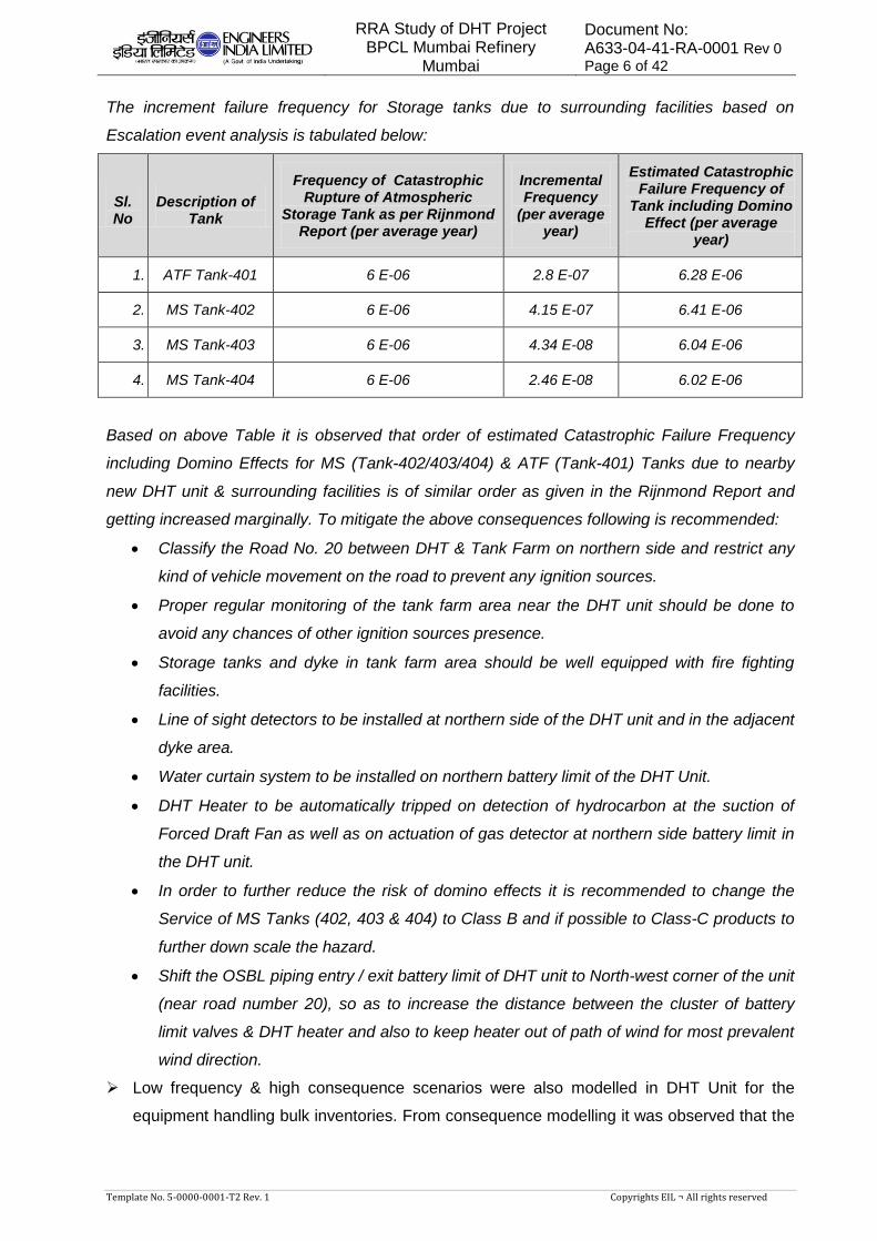
The increment failure frequency for Storage tanks due to surrounding facilities based on
Escalation event analysis is tabulated below:
Sl. No
Description of Tank
Frequency of Catastrophic Rupture of Atmospheric
Storage Tank as per Rijnmond Report (per average year)
Incremental Frequency
(per average year)
Estimated Catastrophic Failure Frequency of
Tank including Domino Effect (per average
year)
1. ATF Tank-401 6 E-06 2.8 E-07 6.28 E-06
2. MS Tank-402 6 E-06 4.15 E-07 6.41 E-06
3. MS Tank-403 6 E-06 4.34 E-08 6.04 E-06
4. MS Tank-404 6 E-06 2.46 E-08 6.02 E-06
Based on above Table it is observed that order of estimated Catastrophic Failure Frequency
including Domino Effects for MS (Tank-402/403/404) & ATF (Tank-401) Tanks due to nearby
new DHT unit & surrounding facilities is of similar order as given in the Rijnmond Report and
getting increased marginally. To mitigate the above consequences following is recommended:
Classify the Road No. 20 between DHT & Tank Farm on northern side and restrict any
kind of vehicle movement on the road to prevent any ignition sources.
Proper regular monitoring of the tank farm area near the DHT unit should be done to
avoid any chances of other ignition sources presence.
Storage tanks and dyke in tank farm area should be well equipped with fire fighting
facilities.
Line of sight detectors to be installed at northern side of the DHT unit and in the adjacent
dyke area.
Water curtain system to be installed on northern battery limit of the DHT Unit.
DHT Heater to be automatically tripped on detection of hydrocarbon at the suction of
Forced Draft Fan as well as on actuation of gas detector at northern side battery limit in
the DHT unit.
In order to further reduce the risk of domino effects it is recommended to change the
Service of MS Tanks (402, 403 & 404) to Class B and if possible to Class-C products to
further down scale the hazard.
Shift the OSBL piping entry / exit battery limit of DHT unit to North-west corner of the unit
(near road number 20), so as to increase the distance between the cluster of battery
limit valves & DHT heater and also to keep heater out of path of wind for most prevalent
wind direction.
Low frequency & high consequence scenarios were also modelled in DHT Unit for the
equipment handling bulk inventories. From consequence modelling it was observed that the

RRA Study of DHT Project BPCL Mumbai Refinery
Mumbai
Document No: A633-04-41-RA-0001 Rev 0
Page 7 of 42
Template No. 5-0000-0001-T2 Rev. 1 Copyrights EIL ¬ All rights reserved
effect zones for Large Hole scenarios in FSD Coalescer, Cold Separator and Stripper
Reflux Drum are crossing the unit’s B/L’s and causing damages.
Being low frequency scenario, outcomes of these scenarios to be utilized for preparation of
the Disaster Management Plan & Emergency Response Guidelines for the Refinery.
Toxic Scenarios were also modelled for the DHT Unit, it was observed that for Stripper
Reflux Drum Ovhd Piping Leak (20 mm), Wild Naphtha Pumps Leak (20 mm), Stripper
Feed/ Bottom Exchanger Flange Leakage (10 mm) and Sour Water Flash Drum Ovhd
Piping Leak (20 mm) scenarios H2S IDLH effect zones may cross the B/L of the DHT Unit
and affect the people, depending upon the direction of the wind at the time of release.
It is recommended to install H2S detectors with sirens at the strategic locations within the
unit, near to the equipment’s handling toxic material. Individual’s to be evacuated on priority
from area around DHT Unit in event of any toxic release from the unit, especially from the
Sulphur Yard and Truck parking. These scenarios to be also utilized for preparation of the
Disaster Management Plan & Emergency Response Guidelines for the Refinery. Wind
socks to be installed near to the DHT unit.
Both high frequency and low frequency scenarios were modelled for the MTBE unit and
analyzed. The Radiation & Blast Overpressure hazard effect zones for various scenarios
modelled for the unit were crossing the unit’s B/L and affecting nearby process units.
It recommended to ensure hydrocarbon detectors at the strategic locations within the unit to
detect any inadvertent leakage from the unit.
Both high frequency and low frequency scenarios were modelled for the various sections of
the CDU/VDU-III and studied. The Radiation & Blast Overpressure hazard effect zones for
various scenarios modelled for the unit were crossing the unit’s B/L and affecting nearby
process units.
It is recommended to ensure hydrocarbon detectors at the strategic locations within the unit
to detect any inadvertent leakage from the unit.
Toxic Scenarios were modelled for the ATU, DHDS SWS and RMP SWS-I/II, it was
observed that H2S IDLH hazard effect zone for various modelled credible scenarios may not
reach ground level but toxic cloud may spread throughout the unit.
It is recommended to ensure H2S detectors with sirens at the strategic locations within the
unit, near to the equipment’s handling toxic material.
Failure scenarios ranging from high frequency to low frequency for various sections of the
HGU were selected and modelled. It was observed that Jet Fire Radiation & Blast
overpressure hazard effect zone for leakage scenarios of Naphtha section may cross unit
B/L & damage the nearby units and affect nearby NSU control room, which is already made
of blast resistant construction.
RRA Study of DHT Project BPCL Mumbai Refinery
Mumbai
Document No: A633-04-41-RA-0001 Rev 0
Page 8 of 42
Template No. 5-0000-0001-T2 Rev. 1 Copyrights EIL ¬ All rights reserved
It recommended to ensure hydrocarbon detectors at the strategic locations within the unit to
detect any inadvertent leakage from the unit.
Tank on fire has been considered as a credible failure scenario in order to assess the
hazard associated with the storage tank. From the consequence analysis it is observed that
8 kW/m2 radiation intensity due to pool fire in the HSD tank may not impact the adjacent
tanks in the dyke. But for high wind condition (5D) adjacent tanks may get affected by 8
kW/m2 radiation intensity.
It is recommended to provide remote actuation of the fire water sprinkler to these tanks for
cooling the tank shell in case of one tank on fire and ensure regular checking of the
sprinkler system. Also, ensure fire fighting arrangement is provided as per OISD guidelines.
GENERAL RECOMMENDATIONS
Ensure usage of safer oxidizing agents (Chlorine free) in Cooling Water circuit.
No operator cabin shall be located inside the battery limit of DHT Unit.
Mitigating measures
Mitigating measures are those measures in place to minimize the loss of containment event and
thereby hazard associated. These include:
Rapid detection of an uncommon event (HC leak, Toxic gas leak, Flame etc.) and alarm
arrangements and development of subsequent quick isolation mechanism for major
inventory.
Measures for controlling / minimization of Ignition sources inside the Refinery complex.
Active and passive fire protection for critical equipment’s and major structures.
Effective Emergency Response plans to be in place.
Detection and isolation
In order to ensure rapid detection of hazardous events the following is recommended:
Ensure installation of flammable / toxic gas detection and fire detectors at strategic locations
for early detection and prevention of an uncommon event emanating from the process
facilities. Once the flammable / toxic gas release has been detected, as the gas or
subsequent fire, toxic and escalation risk will be reduced by isolation of the major inventory
from the release location (prevention of loss of containment). Hence, manual / automated
mechanism is required to isolate the major inventory during any uncommon event.
It is recommended that the storage vessels (column bottom, reflux drum, feed surge drums,
storage tanks etc.) which are dealing with very large inventory should be considered to have
remote operated valves so that these valves can be closed from the safe location upon fire
or flammable gas detection.
RRA Study of DHT Project BPCL Mumbai Refinery
Mumbai
Document No: A633-04-41-RA-0001 Rev 0
Page 9 of 42
Template No. 5-0000-0001-T2 Rev. 1 Copyrights EIL ¬ All rights reserved
Ignition control
Ignition control will reduce the likelihood of fire events. This is the key for reducing the risk
within facilities that process flammable materials. As part of mitigation measure it is strongly
recommended to consider minimize the traffic movement within the refinery complex.
Escape routes
Provide windsocks throughout the site to ensure visibility from all locations. This will enable
people to escape upwind or crosswind from flammable / toxic releases. Sufficient escape routes
from the site should be provided to allow redundancy in escape from all areas.
Preventive maintenance for critical equipment’s
In order to further reduce the probability of catastrophes efficient monitoring of vessel
internals during shut-down to be carried out for Surge Drums & Reflux drums and critical
vessels whose rupture would lead to massive consequences based upon the outcomes of
RRA study.
The vehicles entering the refinery should be ensured to be fitted with spark arrestors.
In order to prevent secondary incident arising from any failure scenario, it is recommended
that sprinklers and other protective devices provided on the tanks to be regularly checked to
ensure that they are functional.
Proper routine check to be ensured in the area to prevent presence of any potential ignition
source in the vicinity of the refinery.
Others
Removal of hammer blinds from the process facilities to be considered.
Closed sampling system to be considered for pressurized services like LPG, Propylene etc.
Whenever a person visits for sampling and maintenance etc. it is always recommended one
should carry portable H2S / Chlorine detectors.
Provide breathing apparatus at strategic locations inside Refinery.
RRA Study of DHT Project BPCL Mumbai Refinery
Mumbai
Document No: A633-04-41-RA-0001 Rev 0
Page 10 of 42
Template No. 5-0000-0001-T2 Rev. 1 Copyrights EIL ¬ All rights reserved
2. INTRODCUTION
2.1 STUDY AIMS AND OBJECTIVE
The objectives of the Rapid Risk Analysis study are to identify and quantify all potential failure
modes that may lead to hazardous consequences and extent. Typical hazardous consequences
include fire, explosion and toxic releases.
The Rapid Risk analysis will also identify potential hazardous consequences having impacts on
population and property in the vicinity of the facilities, and provides information necessary in
developing strategies to prevent accidents and formulate the Disaster Management Plan.
The Rapid Risk Analysis includes the following steps:
a) Identification of failure cases within the process and off-site facilities.
b) Evaluate process hazards emanating from the identified potential accident scenarios.
c) Analyze the damage effects to surroundings due to such incidents.
d) Suggest mitigating measures to reduce the hazard / risk.
The Rapid Risk analysis study has been carried out using the risk assessment software
program ‘PHAST & PHAST RISK’ ver. 6.7/7.1 developed by DNV Technica.
2.2 SCOPE OF WORK
The study addresses the hazards that can be realized due to operations associated with the
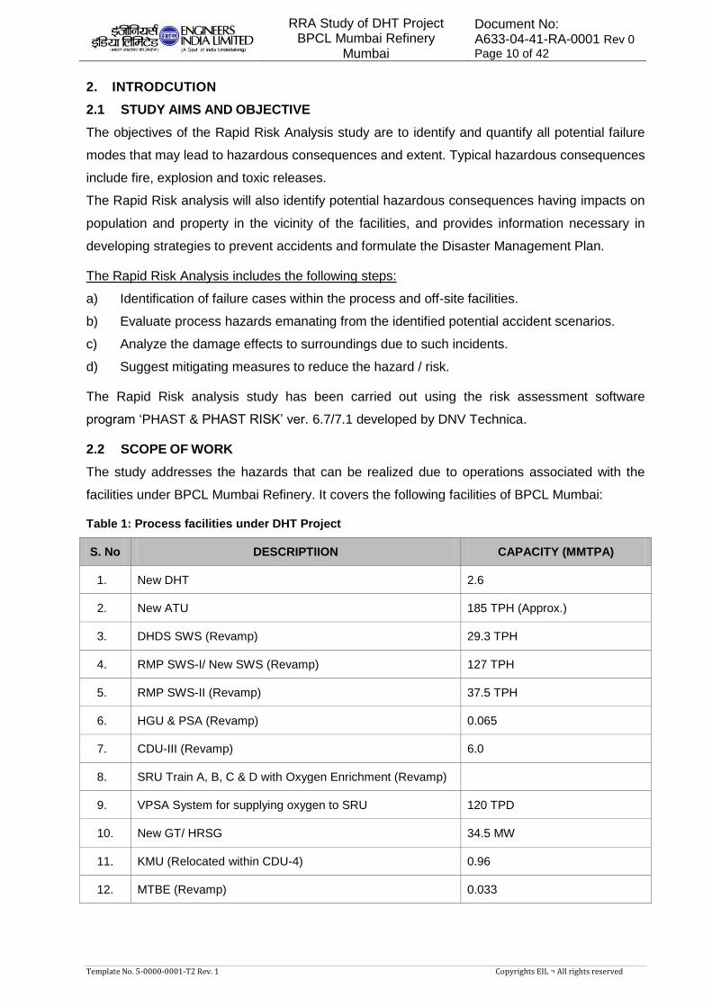
facilities under BPCL Mumbai Refinery. It covers the following facilities of BPCL Mumbai:
Table 1: Process facilities under DHT Project
S. No DESCRIPTIION CAPACITY (MMTPA)
1. New DHT 2.6
2. New ATU 185 TPH (Approx.)
3. DHDS SWS (Revamp) 29.3 TPH
4. RMP SWS-I/ New SWS (Revamp) 127 TPH
5. RMP SWS-II (Revamp) 37.5 TPH
6. HGU & PSA (Revamp) 0.065
7. CDU-III (Revamp) 6.0
8. SRU Train A, B, C & D with Oxygen Enrichment (Revamp)
9. VPSA System for supplying oxygen to SRU 120 TPD
10. New GT/ HRSG 34.5 MW
11. KMU (Relocated within CDU-4) 0.96
12. MTBE (Revamp) 0.033
RRA Study of DHT Project BPCL Mumbai Refinery
Mumbai
Document No: A633-04-41-RA-0001 Rev 0
Page 11 of 42
Template No. 5-0000-0001-T2 Rev. 1 Copyrights EIL ¬ All rights reserved
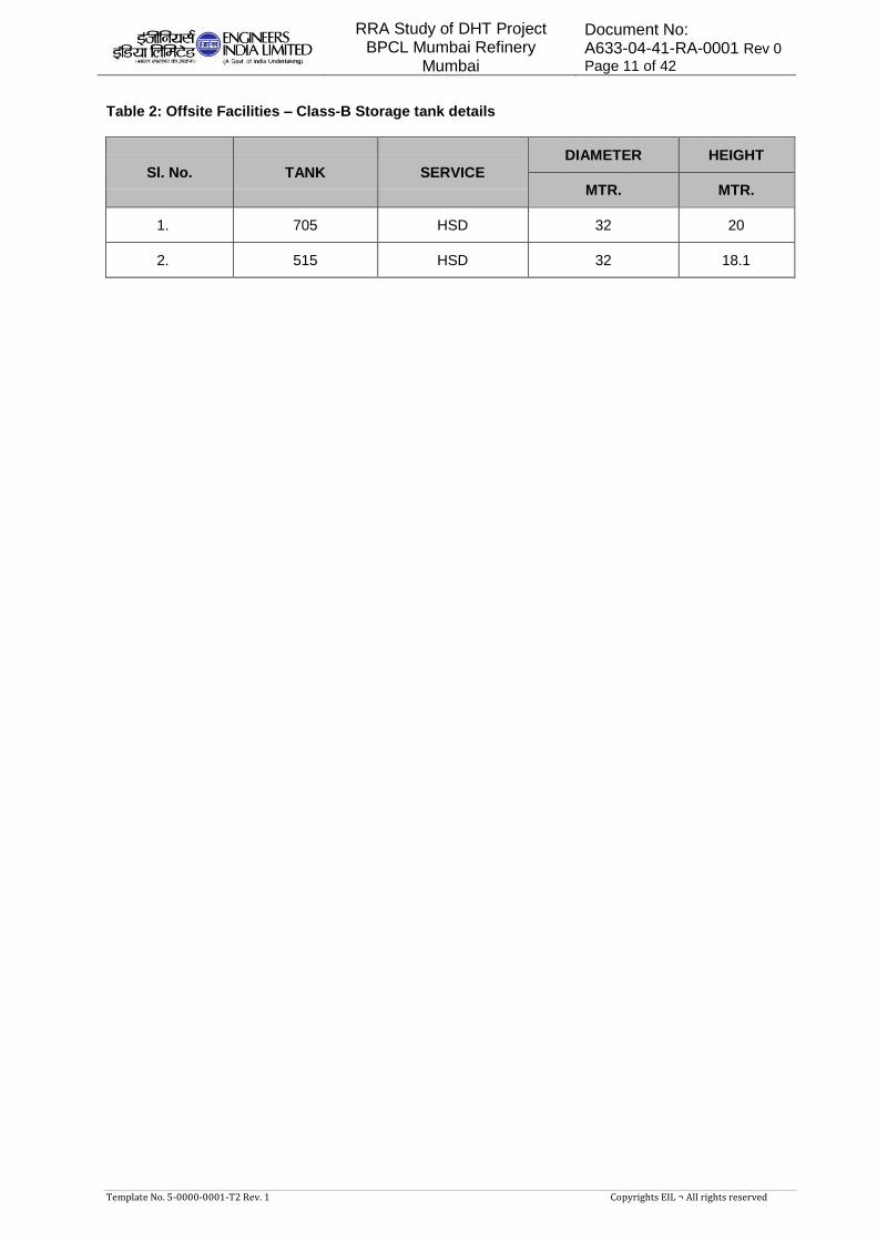
Table 2: Offsite Facilities – Class-B Storage tank details
Sl. No. TANK SERVICE
DIAMETER HEIGHT
MTR. MTR.
1. 705 HSD 32 20
2. 515 HSD 32 18.1
RRA Study of DHT Project BPCL Mumbai Refinery
Mumbai
Document No: A633-04-41-RA-0001 Rev 0
Page 12 of 42
Template No. 5-0000-0001-T2 Rev. 1 Copyrights EIL ¬ All rights reserved
3. SITE CONDITION
3.1 GENERAL
This chapter depicts the location of BPCL Mumbai Refinery complex. It also indicates the
meteorological data, which will be used for the Risk Analysis study.
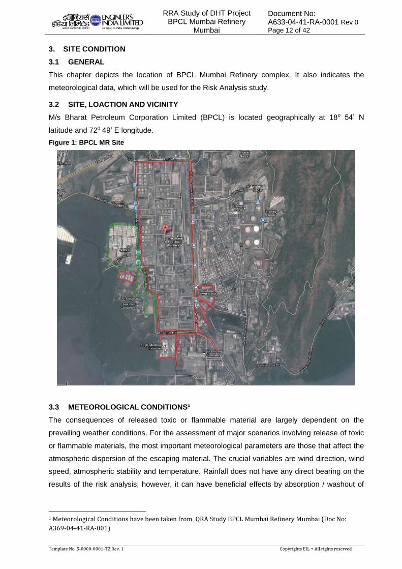
3.2 SITE, LOACTION AND VICINITY
M/s Bharat Petroleum Corporation Limited (BPCL) is located geographically at 180 54’ N
latitude and 720 49’ E longitude.
Figure 1: BPCL MR Site
3.3 METEOROLOGICAL CONDITIONS1
The consequences of released toxic or flammable material are largely dependent on the
prevailing weather conditions. For the assessment of major scenarios involving release of toxic
or flammable materials, the most important meteorological parameters are those that affect the
atmospheric dispersion of the escaping material. The crucial variables are wind direction, wind
speed, atmospheric stability and temperature. Rainfall does not have any direct bearing on the
results of the risk analysis; however, it can have beneficial effects by absorption / washout of
1 Meteorological Conditions have been taken from QRA Study BPCL Mumbai Refinery Mumbai (Doc No:
A369-04-41-RA-001)
RRA Study of DHT Project BPCL Mumbai Refinery
Mumbai
Document No: A633-04-41-RA-0001 Rev 0
Page 13 of 42
Template No. 5-0000-0001-T2 Rev. 1 Copyrights EIL ¬ All rights reserved
released materials. Actual behaviour of any release would largely depend on prevailing weather
condition at the time of release.
For the present Rapid Risk Analysis study, Meteorological data of Mumbai station (nearest
observatory) have been taken from Climatological tables of Observatories in India (1961–1990),
published by India Meteorological Department.
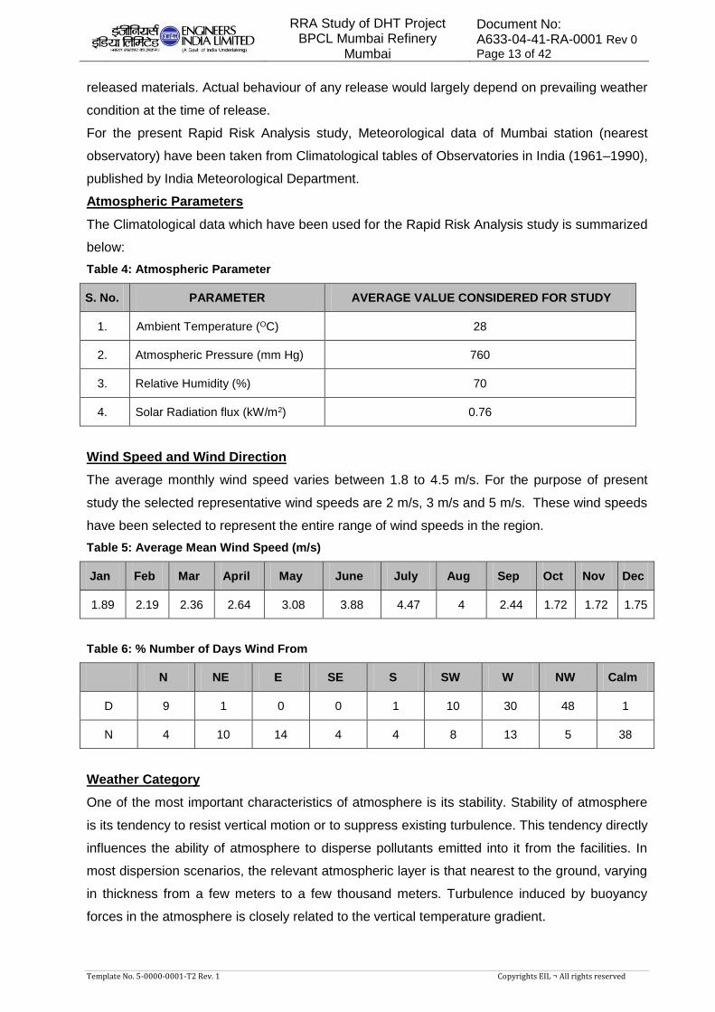
Atmospheric Parameters
The Climatological data which have been used for the Rapid Risk Analysis study is summarized
below:
Table 4: Atmospheric Parameter
S. No. PARAMETER AVERAGE VALUE CONSIDERED FOR STUDY
1. Ambient Temperature (OC) 28
2. Atmospheric Pressure (mm Hg) 760
3. Relative Humidity (%) 70
4. Solar Radiation flux (kW/m2) 0.76
Wind Speed and Wind Direction
The average monthly wind speed varies between 1.8 to 4.5 m/s. For the purpose of present
study the selected representative wind speeds are 2 m/s, 3 m/s and 5 m/s. These wind speeds
have been selected to represent the entire range of wind speeds in the region.
Table 5: Average Mean Wind Speed (m/s)
Jan Feb Mar April May June July Aug Sep Oct Nov Dec
1.89 2.19 2.36 2.64 3.08 3.88 4.47 4 2.44 1.72 1.72 1.75
Table 6: % Number of Days Wind From
N NE E SE S SW W NW Calm
D 9 1 0 0 1 10 30 48 1
N 4 10 14 4 4 8 13 5 38
Weather Category
One of the most important characteristics of atmosphere is its stability. Stability of atmosphere
is its tendency to resist vertical motion or to suppress existing turbulence. This tendency directly
influences the ability of atmosphere to disperse pollutants emitted into it from the facilities. In
most dispersion scenarios, the relevant atmospheric layer is that nearest to the ground, varying
in thickness from a few meters to a few thousand meters. Turbulence induced by buoyancy
forces in the atmosphere is closely related to the vertical temperature gradient.
RRA Study of DHT Project BPCL Mumbai Refinery
Mumbai
Document No: A633-04-41-RA-0001 Rev 0
Page 14 of 42
Template No. 5-0000-0001-T2 Rev. 1 Copyrights EIL ¬ All rights reserved
Temperature normally decreases with increasing height in the atmosphere. The rate at which
the temperature of air decreases with height is called Environmental Lapse Rate (ELR). It will
vary from time to time and from place to place. The atmosphere is said to be stable, neutral or
unstable according to ELR is less than, equal to or greater than Dry Adiabatic Lapse Rate
(DALR), which is a constant value of 0.98°C/100 meters.
Pasquill stability parameter, based on Pasquill – Gifford categorization, is such a meteorological
parameter, which decreases the stability of atmosphere, i.e., the degree of convective
turbulence. Pasquill has defined six stability classes ranging from `A' (extremely unstable) to `F'
(stable). Wind speeds, intensity of solar radiation (daytime insulation) and night time sky cover
have been identified as prime factors defining these stability categories.
When the atmosphere is unstable and wind speeds are moderate or high or gusty, rapid
dispersion of pollutants will occur. Under these conditions, pollutant concentrations in air will be
moderate or low and the material will be dispersed rapidly. When the atmosphere is stable and
wind speed is low, dispersion of material will be limited and pollutant concentration in air will be
high. In general worst dispersion conditions (i.e. contributing to greater hazard distances) occur
during low wind speed and very stable weather conditions, such as that at 2F weather condition
(i.e. 2 m/s wind speed and Pasquill Stability F).
Literature suggests that Category ‘D’ is most probable at coastal sites in moderate climates,
and may occur for up to 80% of the time. Hence, the Pasquill stability category best represented
for the present facilities would be category ‘D’ (neutral).
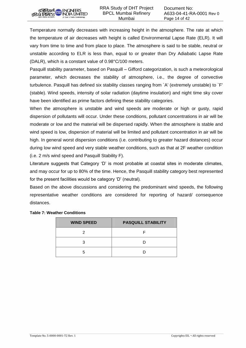
Based on the above discussions and considering the predominant wind speeds, the following
representative weather conditions are considered for reporting of hazard/ consequence
distances.
Table 7: Weather Conditions
WIND SPEED PASQUILL STABILITY
2 F
3 D
5 D

RRA Study of DHT Project BPCL Mumbai Refinery
Mumbai
Document No: A633-04-41-RA-0001 Rev 0
Page 15 of 42
Template No. 5-0000-0001-T2 Rev. 1 Copyrights EIL ¬ All rights reserved
4. HAZARDS ASSOCIATED WITH THE FACILITIES
4.1 GENERAL
Refinery complex handles a number of hazardous materials like LPG, Hydrogen, Naphtha and
other hydrocarbons which have a potential to cause fire and explosion hazards. The toxic
chemicals like Hydrogen sulphide are also being handled in the Refinery. This chapter
describes in brief the hazards associated with these materials.
4.2 HAZARDS ASSOCIATED WITH FLAMMABLE MATERIALS
4.2.1 LIQUIFIED PETROLEUM GAS
LPG is a colourless liquefied gas that is heavier than air and may have a foul smelling odorant
added to it. It is a flammable gas and may cause flash fire and delayed ignition.
LPG is incompatible to oxidizing and combustible materials. It is stable at normal temperatures
and pressure. If it is released at temperatures higher than the normal boiling point it can flash
significantly and would lead to high entrainment of gas phase in the liquid phase. High
entrainment of gas phase in the liquid phase can lead to jet fires. On the other hand negligible
flashing i.e. release of LPG at temperatures near boiling points would lead to formation of pools
and then pool fire. LPG releases may also lead to explosion in case of delayed ignition.
Inhalation of LPG vapours by human beings in considerable concentration may affect the
central nervous system and lead to depression. Inhalation of extremely high concentration of
LPG may lead to death due to suffocation from lack of oxygen. Contact with liquefied LPG may
cause frostbite. Refer to below table for properties of LPG.
Table 8: Hazardous Properties of LPG
S. No. PROPERTIES VALUES
1. LFL (%v/v) 1.7
2. UFL (%v/v) 9.0
3. Auto ignition temperature (°C) 420-540
4. Heat of combustion (Kcal/Kg) 10960
5. Normal Boiling point (°C) -20 to –27
6. Flash point (°C) - 60
4.2.2 HYDROGEN
Hydrogen (H2) is a gas lighter than air at normal temperature and pressure. It is highly
flammable and explosive. It has the widest range of flammable concentrations in air among all
common gaseous fuels. This flammable range of Hydrogen varies from 4% by volume (lower
flammable limit) to 75% by volume (upper flammable limit). Hydrogen flame (or fire) is nearly
invisible even though the flame temperature is higher than that of hydrocarbon fires and hence
poses greater hazards to persons in the vicinity.

RRA Study of DHT Project BPCL Mumbai Refinery
Mumbai
Document No: A633-04-41-RA-0001 Rev 0
Page 16 of 42
Template No. 5-0000-0001-T2 Rev. 1 Copyrights EIL ¬ All rights reserved
Constant exposure of certain types of ferritic steels to hydrogen results in the embrittlement of
the metals. Leakage can be caused by such embrittlement in pipes, welds, and metal gaskets.
In terms of toxicity, hydrogen is a simple asphyxiant. Exposure to high concentrations may
exclude an adequate supply of oxygen to the lungs. No significant effect to human through
dermal absorption and ingestion is reported. Refer to below table for properties of hydrogen.
Table 9: Hazardous Properties of Hydrogen
S. No. PROPERTIES VALUES
1. LFL (%v/v) 4.12
2. UFL (%v/v) 74.2
3. Auto ignition temperature (°C) 500
4. Heat of combustion (Kcal/Kg) 28700
5. Normal Boiling point (°C) -252
6. Flash point (°C) N.A.
4.2.3 NAPHTHA AND OTHER HEAVIER HYDROCARBONS
The major hazards from these types of hydrocarbons are fire and radiation. Any spillage or loss
of containment of heavier hydrocarbons may create a highly flammable pool of liquid around the
source of release.
If it is released at temperatures higher than the normal boiling point it can flash significantly and
would lead to high entrainment of gas phase in the liquid phase. High entrainment of gas phase
in the liquid phase can lead to jet fires. On the other hand negligible flashing i.e. release at
temperatures near boiling points would lead to formation of pools and then pool fire.
Spillage of comparatively lighter hydrocarbons like Naphtha may result in formation of vapour
cloud. Flash fire/ explosion can occur in case of ignition. Refer to below table for properties of
Naphtha.
Table 10: Hazardous Properties of Naphtha
S. No. PROPERTIES VALUES
1. LFL (%v/v) 0.8
2. UFL (%v/v) 5.0
3. Auto ignition temperature (°C) 228
4. Heat of combustion (Kcal//Kg) 10,100
5. Normal Boiling point (°C) 130 -155
6. Flash point (°C) 38 - 42
RRA Study of DHT Project BPCL Mumbai Refinery
Mumbai
Document No: A633-04-41-RA-0001 Rev 0
Page 17 of 42
Template No. 5-0000-0001-T2 Rev. 1 Copyrights EIL ¬ All rights reserved
4.3 HAZARDS ASSOCIATED WITH TOXIC/CARCINOGENIC MATERIALS
4.3.1 HYDROGEN SULPHIDE
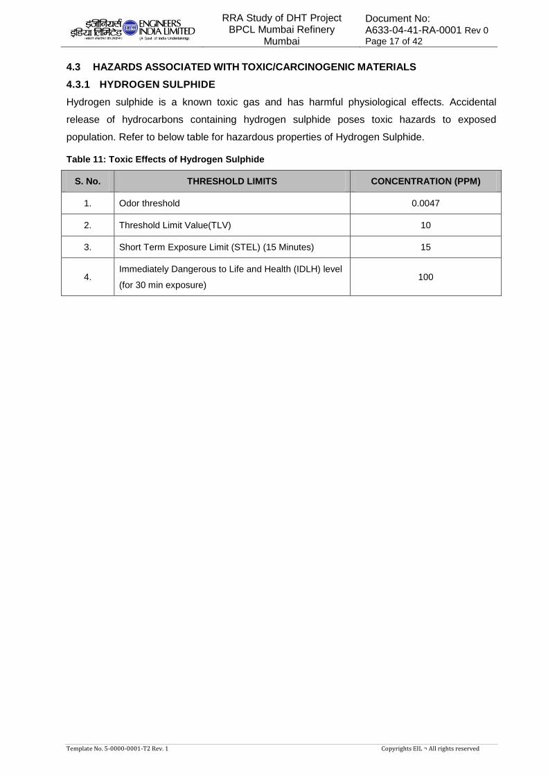
Hydrogen sulphide is a known toxic gas and has harmful physiological effects. Accidental
release of hydrocarbons containing hydrogen sulphide poses toxic hazards to exposed
population. Refer to below table for hazardous properties of Hydrogen Sulphide.
Table 11: Toxic Effects of Hydrogen Sulphide
S. No. THRESHOLD LIMITS CONCENTRATION (PPM)
1. Odor threshold 0.0047
2. Threshold Limit Value(TLV) 10
3. Short Term Exposure Limit (STEL) (15 Minutes) 15
4. Immediately Dangerous to Life and Health (IDLH) level
(for 30 min exposure) 100
RRA Study of DHT Project BPCL Mumbai Refinery
Mumbai
Document No: A633-04-41-RA-0001 Rev 0
Page 18 of 42
Template No. 5-0000-0001-T2 Rev. 1 Copyrights EIL ¬ All rights reserved
5. HAZARD IDENTIFICATION
5.1 GENERAL
A classical definition of hazard states that hazard is in fact the characteristic of
system/plant/process that presents potential for an accident. Hence all the components of a
system/plant/process need to be thoroughly examined in order to assess their potential for
initiating or propagating an unplanned event/sequence of events, which can be termed as an
accident.
In Risk Analysis terminology a hazard is something with the potential to cause harm. Hence the
Hazard Identification step is an exercise that seeks to identify what can go wrong at the major
hazard installation or process in such a way that people may be harmed. The output of this step
is a list of events that need to be passed on to later steps for further analysis.
The potential hazards posed by the facility were identified based on the past accidents, lessons
learnt and a checklist. This list includes the following elements.
Catastrophic rupture of process vessel/ large hole leak from drain line from the process
vessel.
Small hole, cracks or small bore failure (i.e. instrument tapping failure, drains/vents failure
etc.) in piping and vessels.
Flange leaks.
Storage Tank on fire
5.2 MODES OF FAILURE
There are various potential sources of large leakage, which may release hazardous chemicals
and hydrocarbon materials into the atmosphere. These could be in form of gasket failure in
flanged joints, bleeder valve left open inadvertently, an instrument tubing giving way, pump seal
failure, guillotine failure of equipment/ pipeline or any other source of leakage. Operating
experience can identify lots of these sources and their modes of failure. A list of general
equipment and pipeline failure mechanisms is as follows:
Material/Construction Defects
Incorrect selection or supply of materials of construction
Incorrect use of design codes
Weld failures
Failure of inadequate pipeline supports
Pre-Operational Failures
Failure induced during delivery at site
Failure induced during installation
Pressure and temperature effects
Overpressure
Temperature expansion/contraction (improper stress analysis and support design)

RRA Study of DHT Project BPCL Mumbai Refinery
Mumbai
Document No: A633-04-41-RA-0001 Rev 0
Page 19 of 42
Template No. 5-0000-0001-T2 Rev. 1 Copyrights EIL ¬ All rights reserved
Low temperature brittle fracture (if metallurgy is incorrect)
Fatigue loading (cycling and mechanical vibration)
Corrosion Failures
Internal corrosion (e.g. ingress of moisture)
External corrosion
Cladding/insulation failure (e.g. ingress of moisture)
Cathodic protection failure, if provided
Failures due to Operational Errors
Human error
Failure to inspect regularly and identify any defects
External Impact Induced Failures
Dropped objects
Impact from transport such as construction traffic
Vandalism
Subsidence
Strong winds
Failure due to Fire
External fire impinging on pipeline or equipment
Rapid vaporization of cold liquid in contact with hot surfaces
5.3 SELECTED FAILURE CASES
A list of selected failure cases was prepared based on process knowledge, engineering
judgment, experience, past incidents associated with such facilities and considering the general
mechanisms for loss of containment. A list of cases has been identified for the consequence
analysis study based on the following.
Cases with high chance of occurrence but having low consequence:
Example of such failure cases includes two-bolt gasket leak for flanges, instrument
tapping failure at pump discharge, etc. The consequence results will provide enough data
for planning routine safety exercises. This will emphasize the area where operator's
vigilance is essential.
Cases with low chance of occurrence but having high consequence:
Example includes Catastrophic Failure/ Large hole leak of lines, process pressure
vessels, etc.
This approach ensures at least one representative case of all possible types of accidental
failure events, is considered for the consequence analysis. List of scenarios along with the
Hazard distances are attached as Annexure-I. Moreover, the list of scenarios includes at least
one accidental case comprising of release of different sorts of highly hazardous materials

RRA Study of DHT Project BPCL Mumbai Refinery
Mumbai
Document No: A633-04-41-RA-0001 Rev 0
Page 20 of 42
Template No. 5-0000-0001-T2 Rev. 1 Copyrights EIL ¬ All rights reserved
handled in the refinery. Although the scenario list does not give complete failure incidents
considering all equipment’s, units, but the consequence of a similar incident considered in the
scenario list could be used to foresee the consequence of that particular accident.

RRA Study of DHT Project BPCL Mumbai Refinery
Mumbai
Document No: A633-04-41-RA-0001 Rev 0
Page 21 of 42
Template No. 5-0000-0001-T2 Rev. 1 Copyrights EIL ¬ All rights reserved
6. CONSEQUENCE ANALYSIS
6.1 GENERAL
Consequence analysis involves the application of the mathematical, analytical and computer
models for calculation of the effects and damages subsequent to a hydrocarbon / toxic release
accident.
Computer models are used to predict the physical behaviour of hazardous incidents. The model
uses below mentioned techniques to assess the consequences of identified scenarios:
Modeling of discharge rates when holes develop in process equipment/pipe work.
Modeling of the size & shape of the flammable/toxic gas clouds from releases in the
atmosphere.
Modeling of the flame and radiation field of the releases that are ignited and burn as jet
fire, pool fire and flash fire.
Modeling of the explosion fields of releases which are ignited away from the point of
release.
The different consequences (flash fire, pool fire, jet fire and explosion effects) of loss of
containment accidents depend on the sequence of events & properties of material released
leading to the either toxic vapour dispersion, fire or explosion or both.
6.2 CONSEQUENCE ANALYSIS MODELLING
6.2.1 DISCHARGE RATE
The initial rate of release through a leak depends mainly on the pressure inside the equipment,
size of the hole and phase of the release (liquid, gas or two-phase). The release rate decreases
with time as the equipment depressurizes. This reduction depends mainly on the inventory and
the action taken to isolate the leak and blow-down the equipment.
6.2.2 DISPERSION
Releases of gas into the open air form clouds whose dispersion is governed by the wind, by
turbulence around the site, the density of the gas and initial momentum of the release. In case
of flammable materials the sizes of these gas clouds above their Lower Flammable Limit (LFL)
are important in determining whether the release will ignite. In this study, the results of
dispersion modelling for flammable materials are presented LFL quantity.
6.2.3 FLASH FIRE
A flash fire occurs when a cloud of vapours/gas burns without generating any significant
overpressure. The cloud is typically ignited on its edge, remote from- the leak source. The
combustion zone moves through the cloud away from the ignition point. The duration of the
flash fire is relatively short but it may stabilize as a continuous jet fire from the leak source. For
flash fires, an approximate estimate for the extent of the total effect zone is the area over which
the cloud is above the LFL.
RRA Study of DHT Project BPCL Mumbai Refinery
Mumbai
Document No: A633-04-41-RA-0001 Rev 0
Page 22 of 42
Template No. 5-0000-0001-T2 Rev. 1 Copyrights EIL ¬ All rights reserved
6.2.4 JET FIRE
Jet fires are burning jets of gas or atomized liquid whose shape is dominated by the momentum
of the release. The jet flame stabilizes on or close to the point of release and continues until the
release is stopped. Jet fire can be realized, if the leakage is immediately ignited. The effect of
jet flame impingement is severe as it may cut through equipment, pipeline or structure. The
damage effect of thermal radiation is depended on both the level of thermal radiation and
duration of exposure.
6.2.5 POOL FIRE
A cylindrical shape of the pool fire is presumed. Pool-fire calculations are then carried out as
part of an accidental scenario, e.g. in case a hydrocarbon liquid leak from a vessel leads to the
formation of an ignitable liquid pool. First no ignition is assumed, and pool evaporation and
dispersion calculations are being carried out. Subsequently late pool fires (ignition following
spreading of liquid pool) are considered. If the release is bunded, the diameter is given by the
size of the bund. If there is no bund, then the diameter is that which corresponds with a
minimum pool thickness, set by the type of surface on which the pool is spreading.
6.2.6 VAPOR CLOUD EXPLOSION
A vapour cloud explosion (VCE) occurs if a cloud of flammable gas burns sufficiently quickly to
generate high overpressures (i.e. pressures in excess of ambient). The overpressure resulting
from an explosion of hydrocarbon gases is estimated considering the explosive mass available
to be the mass of hydrocarbon vapour between its lower and upper explosive limits.
6.2.7 TOXIC RELEASE
The aim of the toxic risk study is to determine whether the operators in the plant, people
occupied buildings and the public are likely to be affected by toxic substances. Toxic gas cloud
e.g. H2S, etc. was undertaken to the Immediately Dangerous to Life and Health concentration
(IDLH) limit to determine the extent of the toxic hazard created as the result of loss of
containment of a toxic substance.
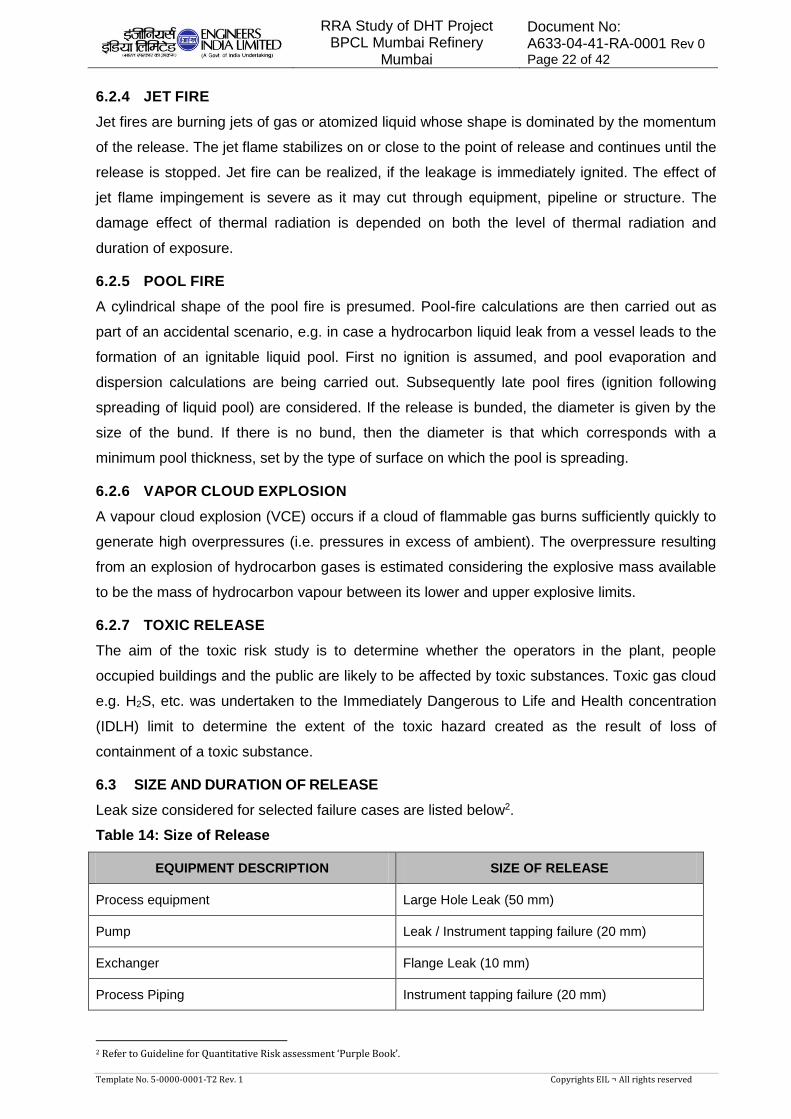
6.3 SIZE AND DURATION OF RELEASE
Leak size considered for selected failure cases are listed below2.
Table 14: Size of Release
EQUIPMENT DESCRIPTION SIZE OF RELEASE
Process equipment Large Hole Leak (50 mm)
Pump Leak / Instrument tapping failure (20 mm)
Exchanger Flange Leak (10 mm)
Process Piping Instrument tapping failure (20 mm)
2 Refer to Guideline for Quantitative Risk assessment ‘Purple Book’.
RRA Study of DHT Project BPCL Mumbai Refinery
Mumbai
Document No: A633-04-41-RA-0001 Rev 0
Page 23 of 42
Template No. 5-0000-0001-T2 Rev. 1 Copyrights EIL ¬ All rights reserved
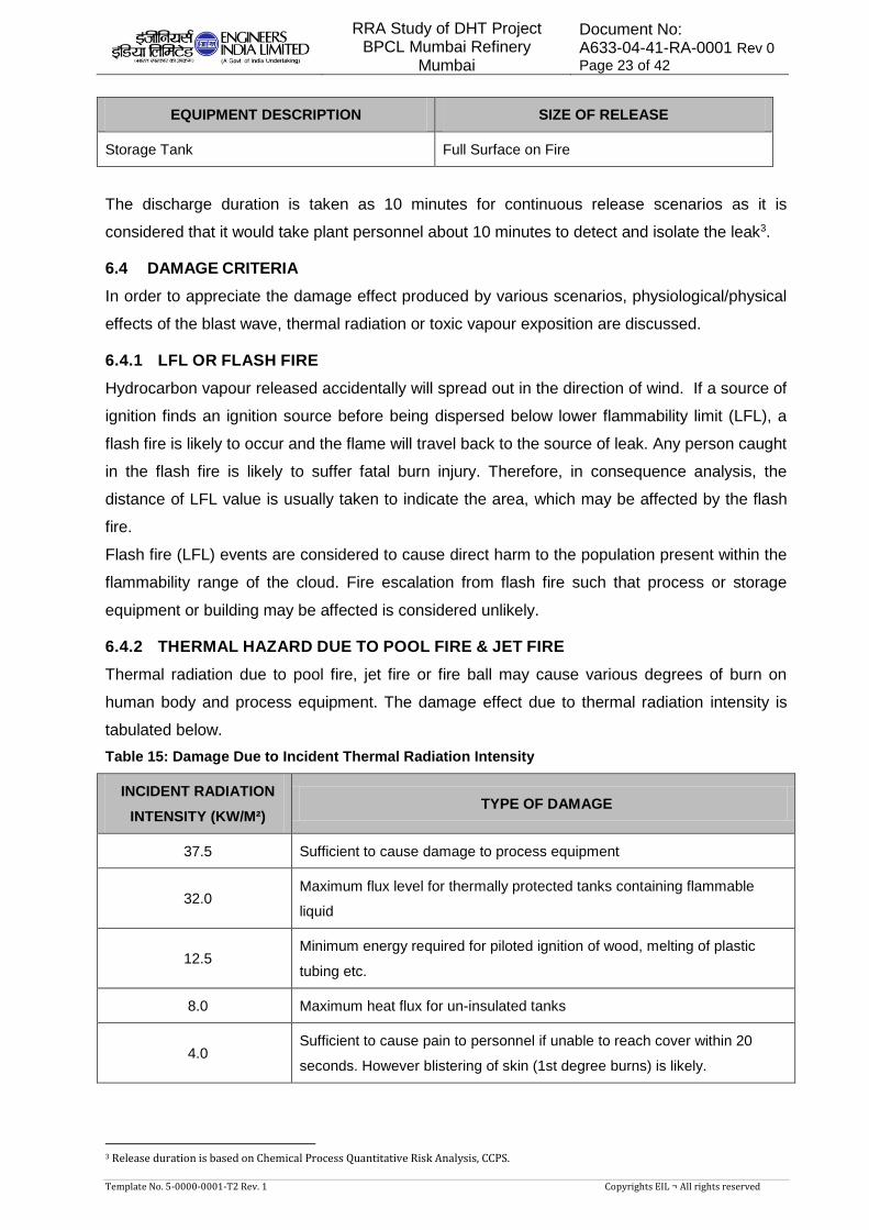
EQUIPMENT DESCRIPTION SIZE OF RELEASE
Storage Tank Full Surface on Fire
The discharge duration is taken as 10 minutes for continuous release scenarios as it is
considered that it would take plant personnel about 10 minutes to detect and isolate the leak3.
6.4 DAMAGE CRITERIA
In order to appreciate the damage effect produced by various scenarios, physiological/physical
effects of the blast wave, thermal radiation or toxic vapour exposition are discussed.
6.4.1 LFL OR FLASH FIRE
Hydrocarbon vapour released accidentally will spread out in the direction of wind. If a source of
ignition finds an ignition source before being dispersed below lower flammability limit (LFL), a
flash fire is likely to occur and the flame will travel back to the source of leak. Any person caught
in the flash fire is likely to suffer fatal burn injury. Therefore, in consequence analysis, the
distance of LFL value is usually taken to indicate the area, which may be affected by the flash
fire.
Flash fire (LFL) events are considered to cause direct harm to the population present within the
flammability range of the cloud. Fire escalation from flash fire such that process or storage
equipment or building may be affected is considered unlikely.
6.4.2 THERMAL HAZARD DUE TO POOL FIRE & JET FIRE
Thermal radiation due to pool fire, jet fire or fire ball may cause various degrees of burn on
human body and process equipment. The damage effect due to thermal radiation intensity is
tabulated below.
Table 15: Damage Due to Incident Thermal Radiation Intensity
INCIDENT RADIATION
INTENSITY (KW/M²) TYPE OF DAMAGE
37.5 Sufficient to cause damage to process equipment
32.0 Maximum flux level for thermally protected tanks containing flammable
liquid
12.5 Minimum energy required for piloted ignition of wood, melting of plastic
tubing etc.
8.0 Maximum heat flux for un-insulated tanks
4.0 Sufficient to cause pain to personnel if unable to reach cover within 20
seconds. However blistering of skin (1st degree burns) is likely.
3 Release duration is based on Chemical Process Quantitative Risk Analysis, CCPS.
RRA Study of DHT Project BPCL Mumbai Refinery
Mumbai
Document No: A633-04-41-RA-0001 Rev 0
Page 24 of 42
Template No. 5-0000-0001-T2 Rev. 1 Copyrights EIL ¬ All rights reserved
The hazard distances to the 37.5 kW/m2, 32 kW/m2, 12.5 kW/m2, 8 kW/m2 and 4 kW/m2
radiation levels, selected based on their effect on population, buildings and equipment were
modelled using PHAST.
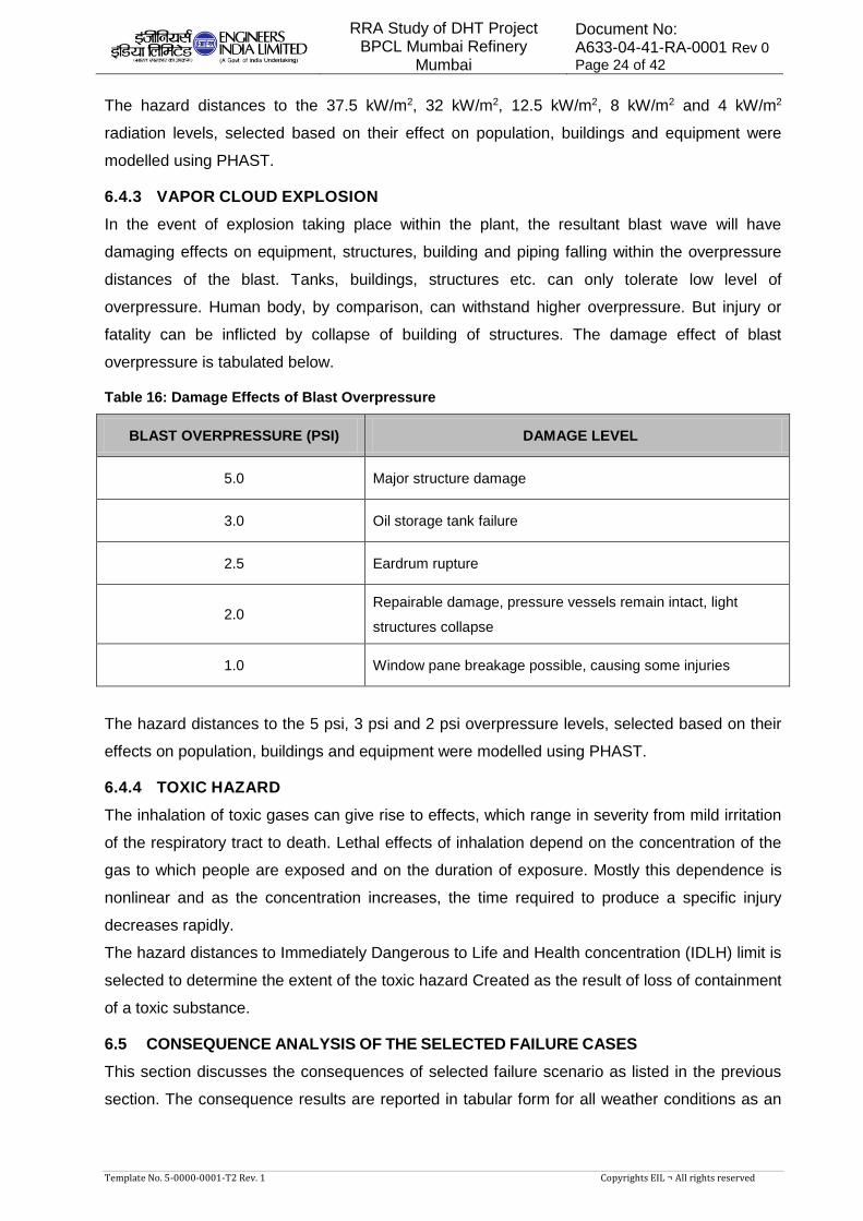
6.4.3 VAPOR CLOUD EXPLOSION
In the event of explosion taking place within the plant, the resultant blast wave will have
damaging effects on equipment, structures, building and piping falling within the overpressure
distances of the blast. Tanks, buildings, structures etc. can only tolerate low level of
overpressure. Human body, by comparison, can withstand higher overpressure. But injury or
fatality can be inflicted by collapse of building of structures. The damage effect of blast
overpressure is tabulated below.
Table 16: Damage Effects of Blast Overpressure
BLAST OVERPRESSURE (PSI) DAMAGE LEVEL
5.0 Major structure damage
3.0 Oil storage tank failure
2.5 Eardrum rupture
2.0 Repairable damage, pressure vessels remain intact, light
structures collapse
1.0 Window pane breakage possible, causing some injuries
The hazard distances to the 5 psi, 3 psi and 2 psi overpressure levels, selected based on their
effects on population, buildings and equipment were modelled using PHAST.
6.4.4 TOXIC HAZARD
The inhalation of toxic gases can give rise to effects, which range in severity from mild irritation
of the respiratory tract to death. Lethal effects of inhalation depend on the concentration of the
gas to which people are exposed and on the duration of exposure. Mostly this dependence is
nonlinear and as the concentration increases, the time required to produce a specific injury
decreases rapidly.
The hazard distances to Immediately Dangerous to Life and Health concentration (IDLH) limit is
selected to determine the extent of the toxic hazard Created as the result of loss of containment
of a toxic substance.
6.5 CONSEQUENCE ANALYSIS OF THE SELECTED FAILURE CASES
This section discusses the consequences of selected failure scenario as listed in the previous
section. The consequence results are reported in tabular form for all weather conditions as an
RRA Study of DHT Project BPCL Mumbai Refinery
Mumbai
Document No: A633-04-41-RA-0001 Rev 0
Page 25 of 42
Template No. 5-0000-0001-T2 Rev. 1 Copyrights EIL ¬ All rights reserved
Annexure-I and are represented graphically in Annexure-II for the selected failure scenario in
a unit causing worst consequences.
6.5.1 NEW DHT UNIT
Cold Feed supply line (Diesel) B/L to Feed Surge Drum Coalescer Leak: Leak of 20 mm as
Instrument Tapping failure in the Cold diesel supply line from OSBL has been considered
as a credible failure scenario to assess the hazard. From the consequence analysis it could
be observed that the LFL would be spreading to distance of 35m from leak source. The Jet
Fire 37.5 & 12.5 kW/m2 intensity would affect zone would be limited to DHT and offsite
pipe-rack. The Pool Fire 12.5 kW/m2 intensity would be mostly producing localized damage
in DHT unit. The 5 & 3 psi blast overpressure affect zone would be localized and mostly
limited to DHT & nearby offsite pipe-rack.
Feed Surge Drum Coalescer: To assess the hazard associated with the unit, large hole
leak (50 mm) in the drain piping from DHT Feed Surge Drum Coalescer has been
considered as a credible failure scenario. From the consequence analysis it is observed
that in case of failure scenario flash fire, jet fire, pool fire and explosion hazard would be
realized. Flash fire in case of failure would have affect zone covering the adjacent MS
tanks in dyke in north of the unit, the SWS, MTBE unit and LBSS/DHDS sub-station in the
west of the unit. While affect due to pool fire would be mostly restricted within the unit
boundary, hazard due to thermal radiation of 37.5 & 12.5 kW/m2 intensity in case of jet fire
would have effect on the adjacent MS tanks. If the vapour cloud generated in case of
failure encounters a ignition source, explosion would be realized. The affect zone of hazard
due to blast overpressure of 5 and 3 psi covers all the adjacent facilities like MS tanks,
NHT/CCR, SWS, MTBE, H2 unit and LBSS/DHDS sub-station.
DHT Feed Pumps: Pumps discharge instrument tapping failure (20 mm) in the DHT feed
pumps have been considered as a credible failure scenario. It is observed from the
consequence analysis that flash fire, jet fire and explosion hazard would be realized. Flash
fire from the feed pumps would affect the adjacent MS tanks in the north of the unit. In case
of jet fire, thermal radiation of 4 kW/m2 intensity would affect the adjacent MS tanks, SWS
unit and LBSS/DHDS sub-station but the 37.5 and 4 kW/m2 radiation intensity would not
affect any facility outside the unit boundary. It is also observed that blast overpressure of 3
and 5 psi would affect all the MS tanks located in the adjacent dyke of the unit as well as
the LBSS/DHDS sub-station and facilities in the SWS and MTBE units.
Cold Separator Drum: Large hole leak (50 mm) in the Cold separator drum has been
considered as a credible failure scenario for risk analysis. It is observed from the
consequence analysis report that flash fire from the drum would affect a wide area covering
all the MS / Naphtha / ATF tanks in the adjacent dyke in the north and LOBS / Benzene /
Toluene tanks in the east of the unit. It’s effect zone would also cover facilities of
NHT/CCR, SWS, MTBE, HDS, H2 unit, LBSS/DHDS sub-station as well as flare stack

RRA Study of DHT Project BPCL Mumbai Refinery
Mumbai
Document No: A633-04-41-RA-0001 Rev 0
Page 26 of 42
Template No. 5-0000-0001-T2 Rev. 1 Copyrights EIL ¬ All rights reserved
located in the west of the unit. Jet Fire radiation intensity of 37.5 and 12.5 kW/m2 would
affect all the adjacent MS tanks in the adjacent dyke and facilities in the SWS and MTBE
units. It is also observed that blast overpressure of 3 and 5 psi would affect all the tanks in
the adjacent dyke in the north of the unit as well as the Naphtha / ATF / SK tanks (tank no
409 / 410 / 411). It would also affect tanks of MS / MTO / FO / LDO / Hexane / LOBS /
Benzene / Toluene as well as facilities in the NHT/CCR, SWS, HDS, MTBE, Aromatics
Recovery and Feed Preparation unit, LBSS/DHS sub-station, flare stack and the new SRR
and S/S near the unit. It is also observed that the hazard due to toxic effect in this failure
scenario would affect up to a distance of approximately 650 meters from the source of leak.
Cold Separator overhead piping: Instrument tapping failure (20 mm) in the Cold Separator
overhead piping has been considered for risk analysis. From the consequence analysis
report it is observed that flash fire, jet fire and explosion hazard would be realized and the
hazard distances in all the cases are mostly restricted within the unit boundary and does
not pose any credible risk to any facility outside the unit. Toxic affect would be extended up
to a distance of 68 m downwind.
2nd Stage Makeup Gas Compressor: Instrument tapping failure (20 mm) in the 2nd Stage
Compressor piping has been considered for risk analysis. It is observed from the
consequence analysis report that flash fire and jet fire hazard would be realized and the
hazard distances are restricted within the unit boundary thereby causing no credible risk to
any facility outside the unit.
Recycle Gas Compressor: Instrument tapping failure (20 mm) in the Recycle Gas
Compressor piping has been considered for risk analysis. It is observed from the
consequence analysis report that flash fire, Jet Fire & Blast overpressure hazard would be
realized and hazard distances would be restricted within the unit boundary for both
Radiation & Explosion.
Stripper Reflux drum: Large hole leak (50 mm) in the Stripper reflux drum has been
considered as a credible failure scenario for risk analysis. It is observed from the
consequence analysis report that the failure scenario would lead to flash fire, jet fire and
explosion hazard. Flash fire from the drum would affect a wide area covering all the MS /
Naphtha / ATF tanks in the adjacent dyke in the north and LOBS / Benzene / Toluene
tanks in the east of the unit. It’s effect zone would also cover facilities of NHT/CCR, SWS,
MTBE, HDS, H2 unit, LBSS/DHDS sub-station as well as flare stack located in the west of
the unit. Jet Fire radiation intensity of 37.5 and 12.5 kW/m2 would affect all the adjacent MS
tanks in the adjacent dyke and facilities in the SWS and MTBE units. It is also observed
that blast overpressure of 3 and 5 psi would affect all the tanks in the adjacent dyke in the
north of the unit as well as the Naphtha/ATF/SK tanks (tank no 409/410/411).It would also
affect tanks of MS/MTO/FO/LDO/Hexane/ LOBS / Benzene / Toluene as well as facilities in
the NHT/CCR, SWS, HDS, MTBE, Aromatics Recovery and Feed Preparation unit,
RRA Study of DHT Project BPCL Mumbai Refinery
Mumbai
Document No: A633-04-41-RA-0001 Rev 0
Page 27 of 42
Template No. 5-0000-0001-T2 Rev. 1 Copyrights EIL ¬ All rights reserved
LBSS/DHS sub-station, flare stack and upcoming SRR and S/S near the unit. The H2S
IDLH hazard zone may extend up to a distance of 500 m, depending upon the weather
conditions at the time of release.
Stripper Reflux drum overhead piping: Instrument tapping failure (20 mm) in the Stripper
Reflux drum overhead piping has been considered as a credible failure scenario for risk
analysis. From the consequence analysis report it is observed that flash fire, jet fire and
explosion hazard would be realized. The hazard due to flash fire, jet fire and explosion
would be restricted within the unit premises thereby causing no considerable risk to any
facility outside the unit The toxic effect would cover a distance of approximately 328 m from
the source of leak thus posing considerable hazard to personnel working is this range from
the unit.
Wild Naphtha pumps: Pump discharge instrument tapping failure (20 mm) in the DHT feed
pumps have been considered as a credible failure scenario. It is observed from the
consequence analysis report the flash fire, jet fire and explosion hazard would be realized.
While jet fire would be mostly restricted within the unit premises, blast overpressure of 3
and 5 psi from the pumps would be affecting the adjacent SWS. The H2S IDLH effect zone
may be extended up to a distance of 110 m, depending upon the weather conditions at the
time of release.
Stripper/Feed Bottom Exchanger: Flange leak (10 mm) in the Stripper/Feed Bottom
Exchanger has been considered for risk analysis. It is observed that flash fire, jet fire and
explosion hazard would be realized and their affect zone would be mostly restricted within
the unit boundary. But the toxic affect due to flange leak would affect hazardously up to a
distance of approximately 65 m from the source of leak.
Diesel Product pumps: Failure of pump discharge instrument tapping (20 mm) in the DHT
Product pumps have been considered as a credible failure scenario. It is observed from the
consequence analysis report the flash fire, jet fire and explosion hazard would be realized.
Flash fire from the pumps would affect the adjacent MS tanks in the north of the unit and
the facilities in the SWS, MTBE unit in the south, while blast overpressure of 3 and 5 psi in
addition to the adjacent MS tanks would also affect the Benzene and toluene tanks and
facilities in the NHT/CCR, SWS and MTBE units.
Diesel Product line piping: Instrument tapping failure (20 mm) in the Diesel Product piping
has been considered for risk analysis. From the consequence analysis report it is flash fire,
jet fire and explosion will be realized. Flash fire from the pumps would affect one of the MS
tanks in the adjacent dyke and flare stack and facilities in the H2 unit. While jet fire would
have no affect outside the unit boundary, blast overpressure of 3 and 5 psi would affect
LBSS/DSHDS sub-station, flare stack, H2 unit and the new S/S near the unit.
Sour Water Flash drum overhead piping: Instrument tapping failure (20 mm) in the
overhead piping of the Sour Water Flash drum has been considered for risk analysis. It is
RRA Study of DHT Project BPCL Mumbai Refinery
Mumbai
Document No: A633-04-41-RA-0001 Rev 0
Page 28 of 42
Template No. 5-0000-0001-T2 Rev. 1 Copyrights EIL ¬ All rights reserved
observed that the failure scenario would lead to flash fire hazard but their affect zone would
be mostly restricted within the unit boundary. But the toxic effect would cover a distance of
up to 92 m from the source of leak.
6.5.2 KMU
Booster pumps: Pump discharge Instrument Tapping failure (20 mm) in the KMU Booster
pumps has been considered as a credible failure scenario for risk analysis. It is observed
from the report that flash fire effect zone is localized within the unit. The Jet fire radiation
effect zone and blast overpressure hazard is restricted mostly within the unit boundary and
does not reach any nearby facility.
6.5.3 ATU
Amine Regeneration Reflux drum overhead piping (acid gas to SRU): Instrument tapping
failure (20 mm) in the Amine Regeneration Reflux drum overhead piping has been
considered for risk analysis. From the report it is observed that the flash fire hazard would
be realized. Hazard due to flash fire would be restricted within the unit boundary. But the
toxic effect due to the H2S leak would affect hazardously up to a distance of more the 80 m
from the source of leak.
6.5.4 MTBE
Piping from Battery limit to Feed Surge drum: Instrument tapping failure (20 mm) in the
piping from battery limit to Feed Surge drum is considered for risk analysis. From the
consequence analysis report it is observed that flash fire, jet fire and explosion hazard
would be realized. While the flash fire and thermal radiation of 37.5 and 12.5 kW/m2
intensity in case of jet fire would affect only the facilities in the adjacent SWS unit, hazard
due to blast overpressure of 3 and 5 psi would affect the LBSS/DHDS sub-station in
addition to the facilities in the SWS unit.
Feed Surge drum: Large hole leak (50 mm) in the MTBE Feed Surge drum has been
considered for risk analysis. From the consequence analysis report it is observed that the
flash fire would affect the facilities of new DHT unit, LBSS/DHDS sub-station along with
those of SWS, HDS and H2 unit. Thermal radiation of 37.5 and 12.5 kW/m2 intensity in
case of jet fire would affect the LBSS/DHDS sub-station and facilities in the SWS, HDS and
new DHT unit. Blast overpressure of 3 and 5 psi would affect LBSS/DHDS sub-station and
facilities in the NHT/CCR, SWS, H2, HDS, DHDS, FPU and new DHT unit.
Feed pumps: Pump discharge instrument tapping failure (20 mm) in the MTBE feed pumps
have been considered for risk analysis. From the consequence analysis report it is
observed that flash fire, jet fire and explosion hazard would be realized. Flash fire, thermal
radiation of 12.5 and 4 kW/m2 intensity in case of jet fire and blast overpressure of 3 and 5
psi in case of explosion hazard would affect the facilities in the adjacent SWS, HDS unit,
new DHT and LBSS/DHDS sub-station.

RRA Study of DHT Project BPCL Mumbai Refinery
Mumbai
Document No: A633-04-41-RA-0001 Rev 0
Page 29 of 42
Template No. 5-0000-0001-T2 Rev. 1 Copyrights EIL ¬ All rights reserved
Fractionation Tower Reflux drum: Large hole leak (50 mm) in the Fractionation Tower
Reflux drum has been considered for risk analysis. From the consequence analysis report
it is observed that this failure case would lead to flash fire, jet fire and explosion hazard.
Flash fire and thermal radiation of 12.5 and 4 kW/m2 intensity in case of jet fire would have
effect on the adjacent SWS, HDS, NHT/CCR, new DHT unit and LBSS/DHDS sub-station.
Similarly blast overpressure of 3 and 5 psi would also have effect on the adjacent SWS,
HDS, NHT/CCR, upcoming DHT unit and LBSS/DHDS sub-station.
C4 Recycle pumps: Pump discharge instrument tapping failure (20 mm) in the C4 Recycle
pumps have been considered for risk analysis. From the consequence analysis report it is
observed that flash fire, jet fire and explosion hazard would be realized. While flash fire and
thermal radiation of 37.5 and 12.5 kW/m2 in case of jet fire would affect only the adjacent
SWS unit, blast overpressure of 3 and 5 psi would in addition to the adjacent SWS unit also
affect the new DHT unit.
Methanol MTBE Reactor Feed pumps: Pump discharge instrument tapping failure (20 mm)
in the C4 Recycle pumps have been considered for risk analysis. From the consequence
analysis report it is observed that the failure scenario would have flash fire, jet fire and
explosion hazard. While flash fire and thermal radiation of 37.5 and 12.5 kW/m2 in case of
jet fire would affect only the adjacent SWS unit, blast overpressure of 3 and 5 psi would in
addition to the adjacent SWS unit also affect the new DHT unit.
MTBE Product pumps: Pump discharge instrument tapping failure (20 mm) of the C4
Recycle pumps have been considered for risk analysis. From the consequence analysis
report it is observed that flash fire, jet fire and explosion hazard would be realized. Flash
fire, thermal radiation of 37.5 and 12.5 kW/m2 in case of jet fire and blast overpressure of 3
and 5 psi would affect only the adjacent SWS unit.
6.5.5 CDU-III
Crude Charge pumps: Pump discharge instrument tapping failure (20 mm) in the Crude
Charge pumps have been considered for risk analysis. From the consequence analysis
report it is observed that flash fire, jet fire and explosion hazard would be realized. It is
observed that the flash fire would be affecting the adjacent SR and LSHS tanks and
facilities in the relocated KMU. Thermal radiation of 37.5 and 12.5 kW/m2 intensity in case
of jet fire would have affect zone restricted within the unit boundary whereas the blast
overpressure of 3 and 5 psi would affect the adjacent LSHS / SR tanks and facilities in the
BBU, CDU and relocated KMU.
Preflash drum: Large hole leak (50 mm) in the Preflash drum is assumed as a credible
failure case. It is observed that the failure scenario would lead to flash fire, jet fire , pool fire
and explosion hazard. While flash fire would have affect zone covering all the adjacent
facilities of BBU, HGU, HCU, KMU, CDU and NSU units as well as Bitumen / Asphalt / SR /
LSHS tanks and the Bitumen filling area. The hazard due to thermal radiation of 37.5 and
RRA Study of DHT Project BPCL Mumbai Refinery
Mumbai
Document No: A633-04-41-RA-0001 Rev 0
Page 30 of 42
Template No. 5-0000-0001-T2 Rev. 1 Copyrights EIL ¬ All rights reserved
12.5 kW/m2 intensity would have affect only on the adjacent HGU and CDU units. The blast
overpressure of 3 and 5 psi would cover a wide area covering all the adjacent facilities of
BBU, HGU, HCU, KMU, CDU, NSU, FFCU, CCU, new GTG/HRSG and new VPSA units
as well as Bitumen / Asphalt / SR / LSHS tanks and the Bitumen filling area. Also it is
observed that 2 and 3 psi blast overpressure affect zone is reaching outside the refinery
boundary. Thus ERP and DMP guidelines need to be properly outlined so that the proper
mitigating measures are carried out immediately in case of such scenario.
Preflash Crude pumps: Pump discharge instrument tapping failure (20 mm) in the Preflash
Crude pumps have been considered for risk analysis. From the consequence analysis
report it is observed that flash fire, jet fire and explosion hazard would be realized. While
flash fire in case of failure scenario would have effect on the adjacent LSHS tanks and the
relocated KMU, affect zone for the thermal radiation of 37.5 and 12.5 kW/m2 in case of jet
fire would have been restricted within the unit boundary whereas the blast overpressure of
3 and 5 psi would affect the adjacent LSHS / SR tanks and facilities in the relocated KMU.
Atmospheric Column Reflux drum: Large hole leak (50 mm) in the Atmospheric Column
Reflux drum has been taken as a credible failure scenario. It is observed that hazard due to
flash fire would have effect on the nearby KMU and Asphalt / SR / LSHS tanks. Hazard
zone due to thermal radiation intensity of 37.5 and 12.5 kW/m2 would cover the adjacent
SR / LSHS tanks while radiation intensity of 4 kW/m2 would also affect the BBU P/H and
relocated KMU unit. Blast overpressure of 5 and 3 psi would in addition to the SR and
LSHS tanks also affect the Bitumen tanks, HGU, CDU, BBU P/H and relocated KMU. It is
also observed from the report that blast overpressure of 2, 3 and 5 psi reaches outside the
unit boundary thereby posing threat to the outside population.
Atmospheric Column Reflux pumps: Pump discharge instrument tapping failure (20 mm) in
the Atmospheric Column Reflux pumps have been considered for risk analysis. From the
consequence analysis report it is observed that flash fire, jet fire and explosion hazard
would be realized. Flash fire would have effect on the adjacent Asphalt, SR tanks, HGU
and BBU P/H. Thermal radiation of 12.5 kW/m2 in case of jet fire would have effect on BBU
SW/H whereas the blast overpressure of 3 and 5 psi would affect the adjacent Asphalt /
Bitumen / LSHS / SR tanks, HGU, BBU unit and the Bitumen filling area.
Overhead Naphtha Accumulator: Large hole leak (50 mm) in the Overhead Naphtha
Accumulator has been taken as a credible failure scenario for risk analysis. It is observed
from the report that the flash fire and blast overpressure of 5 and 3 psi would affect the
adjacent Asphalt / Bitumen / SR / LSHS tanks, facilities in the HGU, Bitumen filling area
and BBU P/H. In case of jet fire thermal radiation of 37.4 and 12.5 kW/m2 intensity would
have hazardous effect only on the Asphalt tanks, facilities of BBU P/H and nearby HGU
unit. Blast overpressure of 3 and 5 psi would have affect zone covering the adjacent
Asphalt / Bitumen / SR / LSHS tanks, facilities in the HGU, Bitumen filling area, Polybag

RRA Study of DHT Project BPCL Mumbai Refinery
Mumbai
Document No: A633-04-41-RA-0001 Rev 0
Page 31 of 42
Template No. 5-0000-0001-T2 Rev. 1 Copyrights EIL ¬ All rights reserved
Packed Bitumen unit, CDU and BBU P/H. It is also observed that 2, 3 and 5 psi blast
overpressure effects reaches the E&C Project yard, office near the RMP control room and
even to the outside population.
Stabilizer Feed pumps: Pump discharge instrument tapping failure (20 mm) in the Stabilizer
Feed pumps have been considered for risk analysis. From the consequence analysis
report it is observed that flash fire, jet fire and explosion hazard would be realized. While
hazard due to thermal radiation of 37.5 and 12.5 kW/m2 intensity in case of jet / pool fire
would have affect zone mostly restricted within the unit boundary, flash fire would have
effect on the adjacent Asphalt / SR tanks, facilities in the HGU and BBU P/H. Blast
overpressure of 3 and 5 psi would also have affect zone covering the adjacent Bitumen /
Asphalt / SR / LSHS tanks, facilities in the HGU, CDU and BBU P/H
Heavy Naphtha Product pumps: Pump discharge instrument tapping failure (20 mm) of the
Heavy Naphtha Product pump have been considered for risk analysis. From the
consequence analysis report it is observed that flash fire, jet fire and explosion hazard
would be realized. Hazard due to thermal radiation of 37.5 and 12.5 kW/m2 intensity in
case of jet fire would have affect zone mostly restricted within the unit boundary, flash fire
and blast overpressure of 3 and 5 psi would affect the adjacent Asphalt/SR tanks, facilities
in the HGU and BBU P/H.
Light Kero Product pumps: Pump discharge instrument tapping failure (20 mm) in the Light
Kero Product pumps have been considered for risk analysis. From the consequence
analysis report it is observed that flash fire, jet / pool fire and explosion hazard would be
realized and the hazard zone in all the cases would be mostly restricted within the unit
boundary. Thereby posing no considerable risk to any facility outside the unit.
Stabilizer Reflux drum: Large hole leak (50 mm) in the Stabilizer Reflux drum has been
taken as a credible failure scenario for risk analysis. From the report it is observed that the
flash fire in case of failure scenario would have affect on a wide area covering all the
nearby Asphalt / Bitumen / SR / LSHS tanks, facilities in the RMP control room, Bitumen
filling area, Polybag Packed Bitumen unit, HGU, NSU, KMU, BBU P/H and even covers the
E&C Project yard and to the population outside the refinery boundary. The affect zone due
to thermal radiation of 37.5 and 12.5 kW/m2 intensity in case of jet fire and blast
overpressure of 5 and 3 psi would have effect on the nearby Asphalt / Bitumen / SR tanks
and facilities of HGU and BBU P/H. If the vapor cloud encounters an ignition source then
explosion hazard would be realized. From the consequence report it is observed that blast
overpressure of 2, 3 and 5 psi would have effect on a very wide area covering the nearby
Asphalt / Bitumen / SR / LSHS tanks, facilities in the RMP control room, Bitumen filling
area, Polybag Packed Bitumen unit, N2 plant, VPSA, FCCU, CCU, HGU, NSU, CDU, KMU,
new GTG / HRSG, BBU P/H and even covers the E&C Project yard and to the population
outside the refinery boundary.
RRA Study of DHT Project BPCL Mumbai Refinery
Mumbai
Document No: A633-04-41-RA-0001 Rev 0
Page 32 of 42
Template No. 5-0000-0001-T2 Rev. 1 Copyrights EIL ¬ All rights reserved
LPG Product piping: Instrument tapping failure (20 mm) in the LPG Product piping have
been considered for risk analysis. From the consequence analysis report it is observed that
flash fire, jet fire and explosion hazard would be realized and the hazard zone in all the
cases would be mostly restricted within the unit boundary.
6.5.6 DHDS SWS
Stripper-I overhead piping: Instrument tapping failure (20 mm) in the Stripper-I overhead
piping has been considered for risk analysis. From the consequence analysis report it is
observed that flash fire would be realized which would be mostly restricted within the unit
boundary. But the toxic affect due to the leak would have hazardous affect up to a distance
of 200 m from the source of leak, depending upon direction of wind. The H2S IDLH may not
reach the ground level.
Stripper-II overhead piping: Instrument tapping failure (20 mm) in the Stripper-II overhead
piping has been considered for risk analysis. The consequence analysis report it is
observed that flash fire would be realized whose affect zone would be mostly restricted
within the unit boundary. The toxic affect due to the leak would also be restricted within the
unit boundary. The H2S IDLH may not reach the ground level.
6.5.7 RMP SWS-I
Stripper overhead piping: Instrument tapping failure (20 mm) in the RMP Stripper overhead
piping has been considered for risk analysis. From the consequence analysis report it is
observed that flash fire would be realized and its affect would be mostly restricted within
the unit boundary. But the toxic affect due to the leak would have hazardous effect up to a
distance of 17 m from the source of leak. The H2S IDLH may not reach the ground level.
6.5.8 RMP SWS-II
Stripper-I overhead piping: Instrument tapping failure (20 mm) in the Stripper-I overhead
piping has been considered for risk analysis. This scenario would lead to flash fire whose
hazardous affect zone would be mostly restricted within the unit boundary. But the toxic
affect due to the leak would have hazardous affect up to a distance of 205 m from the
source of leak. The H2S IDLH may not reach the ground level.
Stripper-II overhead piping: Instrument tapping failure (20 mm) in the Stripper-II overhead
piping has been considered for risk analysis. From the consequence analysis report it is
observed that flash fire would be realized which would be mostly restricted inside the unit
boundary limit. The toxic affect due to the leak also would also have affect restricted within
the unit boundary. The H2S IDLH may not reach the ground level.
6.5.9 HGU-II
Feed piping from Battery limit to Naphtha Deareator: Instrument tapping failure (20 mm) in
the Feed piping from Battery limit to Naphtha Deareator has been considered for risk
analysis. From the consequence analysis report it is observed that flash fire, jet / pool fire
RRA Study of DHT Project BPCL Mumbai Refinery
Mumbai
Document No: A633-04-41-RA-0001 Rev 0
Page 33 of 42
Template No. 5-0000-0001-T2 Rev. 1 Copyrights EIL ¬ All rights reserved
and explosion hazard would be realized. Flash fire from the leak would have effect zone
covering facilities in the adjacent CDU/VDU-III, KMU and NSU. While hazard due to
thermal radiation of 37.5 and 12.5 kW/m2 intensity in case of jet fire would be mostly
restricted within the unit boundary the hazard due to blast overpressure of 3 and 5 psi
would affect the adjacent CDU/VDU-III, KMU, NSU and NSU control room.
Naphtha Deareator Surge drum: Large hole leak (50 mm) in the Naphtha Deareator Surge
drum has been taken as a credible failure scenario for risk analysis. From the report it is
observed that the effect zone due to flash fire would cover the adjacent Bitumen and
Asphalt tanks, Polybag Packed Bitumen unit, Bitumen filling area and facilities in the
nearby NSU, HCU, KMU and CDU/VDU-III units. Hazard due to thermal radiation of 4
kW/m2 intensity would have similar affect zone as in case of flash fire but the thermal
radiation of 37.5 and 12.5 kW/m2 intensity would affect only the adjacent NSU, HCU, KMU
and CDU/VDU-III. If the vapour cloud in case of failure encounters any ignition source
explosion would be realized. Blast overpressure of 5 and 3 psi would have hazardous
effect on the adjacent Bitumen and Asphalt tanks, Polybag Packed Bitumen unit, Bitumen
filling area and facilities in the nearby NSU, HCU, KMU, CDU-III, FCCU units, the new
VPSA and N2 plant.
Naphtha Feed pumps: Pump discharge instrument tapping failure (20 mm) in the Naphtha
Feed pumps have been considered for risk analysis. From the consequence analysis
report it is observed that flash fire, jet fire and explosion hazard would be realized. Hazard
due to flash fire and thermal radiation of 37.5 and 12.5 kW/m2 intensity would be mostly
restricted within the unit boundary but the hazard due to blast overpressure of 3 and 5 psi
would have affect zone covering the adjacent HCU, KMU and CDU/VDU-III.
Pre-reformer: Instrument tapping failure (20 mm) in the Pre-reformer has been considered
for risk analysis. From the consequence analysis report it is observed that flash fire hazard
would be realized and the hazard zone would be mostly restricted within the unit boundary.
Piping from reformer to MT Shift Converter: Instrument tapping failure (20 mm) in the
piping from reformer to MT Shift Converter has been considered for risk analysis. From the
consequence analysis report it is observed that flash fire would be realized and the hazard
zone would be mostly restricted within the unit boundary.
PSA & its piping: Instrument tapping failure (20 mm) in the PSA & its piping has been
considered for risk analysis. From the consequence analysis report it is observed that flash
fire hazard would be realized and the hazard zone would be mostly restricted within the
unit boundary.
6.5.10 OFFSITES
HSD Storage Tank (Tank No. 515) on Fire: Tank on fire has been modeled to assess the
hazard associated with the storage tank. From the consequence analysis it is observed
that 8 kW/m2 radiation intensity due to pool fire in the HSD tank may not impact the
RRA Study of DHT Project BPCL Mumbai Refinery
Mumbai
Document No: A633-04-41-RA-0001 Rev 0
Page 34 of 42
Template No. 5-0000-0001-T2 Rev. 1 Copyrights EIL ¬ All rights reserved
adjacent tanks in the dyke. But for high wind condition (5D) adjacent tanks may get
affected by 8 kW/m2 radiation intensity.
RLNG line to New GTG: Leak (20 mm) in the RLNG line to New GTG have been
considered for risk analysis. From the consequence analysis report it is observed that flash
fire, jet fire and explosion hazard would be realized. Hazard due to flash fire and thermal
radiation of 32 and 8 kW/m2 intensity would be mostly restricted within the unit boundary.
The hazard due to blast overpressure of 3 and 5 psi would also be limited to units B/L
depending upon the location of leak and prevalent wind condition.
DHT Feed Pump: Leak of (20 mm) in the discharge of DHT Feed Pump has been
considered for risk analysis. From the consequence analysis report it is observed that flash
fire, jet fire and explosion hazard would be realized. Thermal radiation of 32 and 8 kW/m2
intensity due to Jet Fire may affect the nearby BHGO Tank (T-704) and foreman office. The
blast overpressure of 5 & 3 psi may affect the BHGO Tank (T-704) and foreman office,
depending upon the prevalent weather conditions at the time of release. The 8 kW/m2
intensity due to Pool Fire may affect the nearby BHGO Tank (T-704).
RRA Study of DHT Project BPCL Mumbai Refinery
Mumbai
Document No: A633-04-41-RA-0001 Rev 0
Page 35 of 42
Template No. 5-0000-0001-T2 Rev. 1 Copyrights EIL ¬ All rights reserved
7. MAJOR FINDINGS AND RECOMMENDATIONS
The major findings and recommendations arising out of the Rapid Risk analysis study for DHT
Project of BPCL Mumbai Refinery are summarized below:
Consequence modelling for High frequency scenarios of DHT unit was carried out and it
was observed that 5 & 3 psi blast overpressure effect zones in the event of DHT Feed
Pump Leak (20 mm), Diesel Product Pumps Leak (20 mm) and Instrument Tapping Failure
in the Diesel product piping may affect the adjacent MS / ATF tankages in the north of the
DHT unit, depending upon the prevalent wind conditions & ignition source encountered at
the time of release. This increases the likelihood of triggering domino effect which may be
highly damaging to the refinery.
These scenarios were further evaluated in details by limiting the hydrocarbon mass in
vapour cloud by considering ignition source at the actual distance from the leakage source.
It is observed that potential source of delayed ignition around the DHT are Heater & traffic
around unit. 5 & 3 psi blast affect zone for DHT Feed Pump Leak (20 mm) is still extends to
MS Tanks.
To evaluate the Domino Effects on MS Tanks (402, 403, 404) & ATF Tanks (401) (Attached
as Annexure-III) further, Escalation event analysis was carried out by accounting the failure
scenarios of DHT & adjoining existing H2 and MTBE unit.
The increment failure frequency for Storage tanks due to surrounding facilities based on
Escalation event analysis is tabulated below:
Sl. No
Description of Tank
Frequency of Catastrophic Rupture of Atmospheric
Storage Tank as per Rijnmond Report (per average year)
Incremental Frequency
(per average year)
Estimated Catastrophic Failure Frequency of
Tank including Domino Effect (per average
year)
1. ATF Tank-401 6 E-06 2.8 E-07 6.28 E-06
2. MS Tank-402 6 E-06 4.15 E-07 6.41 E-06
3. MS Tank-403 6 E-06 4.34 E-08 6.04 E-06
4. MS Tank-404 6 E-06 2.46 E-08 6.02 E-06
Based on above Table it is observed that order of estimated Catastrophic Failure Frequency
including Domino Effects for MS (Tank-402/403/404) & ATF (Tank-401) Tanks due to
nearby new DHT unit & surrounding facilities is of similar order as given in the Rijnmond
Report and getting increased marginally. To mitigate the above consequences following is
recommended:
Classify the Road No. 20 between DHT & Tank Farm on northern side and restrict any
kind of vehicle movement on the road to prevent any ignition sources.
Proper regular monitoring of the tank farm area near the DHT unit should be done to
avoid any chances of other ignition sources presence.

RRA Study of DHT Project BPCL Mumbai Refinery
Mumbai
Document No: A633-04-41-RA-0001 Rev 0
Page 36 of 42
Template No. 5-0000-0001-T2 Rev. 1 Copyrights EIL ¬ All rights reserved
Storage tanks and dyke in tank farm area should be well equipped with fire fighting
facilities.
Line of sight detectors to be installed at northern side of the DHT unit and in the adjacent
dyke area.
Water curtain system to be installed on northern battery limit of the DHT Unit.
DHT Heater to be automatically tripped on detection of hydrocarbon at the suction of
Forced Draft Fan as well as on actuation of gas detector at northern side battery limit in
the DHT unit.
In order to further reduce the risk of domino effects it is recommended to change the
Service of MS Tanks (402, 403 & 404) to Class B and if possible to Class-C products to
further down scale the hazard.
Shift the OSBL piping entry / exit battery limit of DHT unit to North-west corner of the unit
(near road number 20), so as to increase the distance between the cluster of battery
limit valves & DHT heater and also to keep heater out of path of wind for most prevalent
wind direction.
Low frequency & high consequence scenarios were also modelled in DHT Unit for the
equipment handling bulk inventories. From consequence modelling it was observed that the
effect zones for Large Hole scenarios in FSD Coalescer, Cold Separator and Stripper
Reflux Drum are crossing the unit’s B/L’s and causing damages.
Being low frequency scenario, outcomes of these scenarios to be utilized for preparation of
the Disaster Management Plan & Emergency Response Guidelines for the Refinery.
Toxic Scenarios were also modelled for the DHT Unit, it was observed that for Stripper
Reflux Drum Ovhd Piping Leak (20 mm), Wild Naphtha Pumps Leak (20 mm), Stripper
Feed/ Bottom Exchanger Flange Leakage (10 mm) and Sour Water Flash Drum Ovhd
Piping Leak (20 mm) scenarios H2S IDLH effect zones may cross the B/L of the DHT Unit
and affect the people, depending upon the direction of the wind at the time of release.
It is recommended to install H2S detectors with sirens at the strategic locations within the
unit, near to the equipment’s handling toxic material. Individual’s to be evacuated on priority
from area around DHT Unit in event of any toxic release from the unit, especially from the
Sulphur Yard and Truck parking. These scenarios to be also utilized for preparation of the
Disaster Management Plan & Emergency Response Guidelines for the Refinery. Wind
socks to be installed near to the DHT unit.
Both high frequency and low frequency scenarios were modelled for the MTBE unit and
analyzed. The Radiation & Blast Overpressure hazard effect zones for various scenarios
modelled for the unit were crossing the unit’s B/L and affecting nearby process units.
It recommended to ensure hydrocarbon detectors at the strategic locations within the unit to
detect any inadvertent leakage from the unit.
RRA Study of DHT Project BPCL Mumbai Refinery
Mumbai
Document No: A633-04-41-RA-0001 Rev 0
Page 37 of 42
Template No. 5-0000-0001-T2 Rev. 1 Copyrights EIL ¬ All rights reserved
Both high frequency and low frequency scenarios were modelled for the various sections of
the CDU/VDU-III and studied. The Radiation & Blast Overpressure hazard effect zones for
various scenarios modelled for the unit were crossing the unit’s B/L and affecting nearby
process units.
It is recommended to ensure hydrocarbon detectors at the strategic locations within the unit
to detect any inadvertent leakage from the unit.
Toxic Scenarios were modelled for the ATU, DHDS SWS and RMP SWS-I/II, it was
observed that H2S IDLH hazard effect zone for various modelled credible scenarios may not
reach ground level but toxic cloud may spread throughout the unit.
It is recommended to ensure H2S detectors with sirens at the strategic locations within the
unit, near to the equipment’s handling toxic material.
Failure scenarios ranging from high frequency to low frequency for various sections of the
HGU were selected and modelled. It was observed that Jet Fire Radiation & Blast
overpressure hazard effect zone for leakage scenarios of Naphtha section may cross unit
B/L & damage the nearby units and affect nearby NSU control room, which is already made
of blast resistant construction.
It recommended to ensure hydrocarbon detectors at the strategic locations within the unit to
detect any inadvertent leakage from the unit.
Tank on fire has been considered as a credible failure scenario in order to assess the
hazard associated with the storage tank. From the consequence analysis it is observed that
8 kW/m2 radiation intensity due to pool fire in the HSD tank may not impact the adjacent
tanks in the dyke. But for high wind condition (5D) adjacent tanks may get affected by 8
kW/m2 radiation intensity.
It is recommended to provide remote actuation of the fire water sprinkler to these tanks for
cooling the tank shell in case of one tank on fire and ensure regular checking of the
sprinkler system. Also, ensure fire fighting arrangement is provided as per OISD guidelines.
GENERAL RECOMMENDATIONS
Ensure usage of safer oxidizing agents (Chlorine free) in Cooling Water circuit.
No operator cabin shall be located inside the battery limit of DHT Unit.
Mitigating measures
Mitigating measures are those measures in place to minimize the loss of containment event and
thereby hazard associated. These include:
Rapid detection of an uncommon event (HC leak, Toxic gas leak, Flame etc.) and alarm
arrangements and development of subsequent quick isolation mechanism for major
inventory.
Measures for controlling / minimization of Ignition sources inside the Refinery complex.
Active and passive fire protection for critical equipment’s and major structures.
RRA Study of DHT Project BPCL Mumbai Refinery
Mumbai
Document No: A633-04-41-RA-0001 Rev 0
Page 38 of 42
Template No. 5-0000-0001-T2 Rev. 1 Copyrights EIL ¬ All rights reserved
Effective Emergency Response plans to be in place.
Detection and isolation
In order to ensure rapid detection of hazardous events the following is recommended:
Ensure installation of flammable / toxic gas detection and fire detectors at strategic locations
for early detection and prevention of an uncommon event emanating from the process
facilities. Once the flammable / toxic gas release has been detected, as the gas or
subsequent fire, toxic and escalation risk will be reduced by isolation of the major inventory
from the release location (prevention of loss of containment). Hence, manual / automated
mechanism is required to isolate the major inventory during any uncommon event.
It is recommended that the storage vessels (column bottom, reflux drum, feed surge drums,
storage tanks etc.) which are dealing with very large inventory should be considered to have
remote operated valves so that these valves can be closed from the safe location upon fire
or flammable gas detection.
Ignition control
Ignition control will reduce the likelihood of fire events. This is the key for reducing the risk
within facilities that process flammable materials. As part of mitigation measure it is strongly
recommended to consider minimize the traffic movement within the refinery complex.
Escape routes
Provide windsocks throughout the site to ensure visibility from all locations. This will enable
people to escape upwind or crosswind from flammable / toxic releases. Sufficient escape routes
from the site should be provided to allow redundancy in escape from all areas.
Preventive maintenance for critical equipment’s
In order to further reduce the probability of catastrophes efficient monitoring of vessel
internals during shut-down to be carried out for Surge Drums & Reflux drums and critical
vessels whose rupture would lead to massive consequences based upon the outcomes of
RRA study.
The vehicles entering the refinery should be ensured to be fitted with spark arrestors.
In order to prevent secondary incident arising from any failure scenario, it is recommended
that sprinklers and other protective devices provided on the tanks to be regularly checked to
ensure that they are functional.
Proper routine check to be ensured in the area to prevent presence of any potential ignition
source in the vicinity of the refinery.
Others
Removal of hammer blinds from the process facilities to be considered.
Closed sampling system to be considered for pressurized services like LPG, Propylene etc.

RRA Study of DHT Project BPCL Mumbai Refinery
Mumbai
Document No: A633-04-41-RA-0001 Rev 0
Page 39 of 42
Template No. 5-0000-0001-T2 Rev. 1 Copyrights EIL ¬ All rights reserved
Whenever a person visits for sampling and maintenance etc. it is always recommended one
should carry portable H2S / Chlorine detectors.
Provide breathing apparatus at strategic locations inside Refinery.

RRA Study of DHT Project BPCL Mumbai Refinery
Mumbai
Document No: A633-04-41-RA-0001 Rev 0
Page 40 of 42
Template No. 5-0000-0001-T2 Rev. 1 Copyrights EIL ¬ All rights reserved
8. GLOSSARY
CASUALTY Someone who suffers serious injury or worse i.e. including fatal
injuries. As a rough guide fatalities are likely to be half the total
casualties. But this may vary depending on the nature of the event.
HAZARD A chemical or physical condition with the potential of causing
damage.
FLAMMABILITY LIMITS In fuel-air systems, a range of compositions exists inside which a
(UFL – LFL) flame will propagate substantial distance from an
ignition source. The limiting fuel concentrations are termed as Upper
flammability or explosives limit (Fuel concentrations exceeding this
are too rich) and Lower flammability or explosives limit (Fuel
concentrations below this are too lean).
FLASH FIRE The burning of a vapor cloud at very low flame propagation speed.
Combustion products are generated at a rate low enough for
expansion to take place easily without significant overpressure ahead
or behind the flame front. The hazard is therefore only due to thermal
effects.
OVERPRESSURE Maximum pressure above atmosphere pressure experiences during
the passage of a blast wave from an explosion expressed in this
report as pounds per square inch (psi).
EXPLOSION A rapid release of energy, which causes a pressure discontinuity or
shock wave moving away from the source. An explosion can be
produced by detonation of a high explosive or by the rapid burning of
a flammable gas cloud. The resulting overpressure is sufficient to
cause damage inside and outside the cloud as the shock wave
propagation into the atmosphere beyond the cloud. Some authors
use the term deflagration for this type of explosion
DOMINO EFFECT The effect that loss of containment of one installation leads to loss of
containment of other installations
EVENT TREE A logic diagram of success and failure combinations of events used
to identify accident sequences leading to all possible consequences
of a given initiating event.
TLV “Threshold limit value” is defined as the concentration of the
substance in air that can be breathed for five consecutive 8 hours
work day (40 hours work week) by most people without side effect.
RRA Study of DHT Project BPCL Mumbai Refinery
Mumbai
Document No: A633-04-41-RA-0001 Rev 0
Page 41 of 42
Template No. 5-0000-0001-T2 Rev. 1 Copyrights EIL ¬ All rights reserved
STEL “Short Term Exposure Limit” is the maximum permissible average
exposure for the time period specified (15 minutes).
IDLH “Immediate Dangerous to Life and Health” is the maximum
concentration level from which one could escape within 30 minutes
without any escape impairing symptoms.
PASQUILL CLASS Classification to qualify the stability of the atmosphere, indicated by a
letter ranging from A, for very unstable, to F, for stable.
FREQUENCY The number of times an outcome is expected to occur in a given
period of time.
RRA Study of DHT Project BPCL Mumbai Refinery
Mumbai
Document No: A633-04-41-RA-0001 Rev 0
Page 42 of 42
Template No. 5-0000-0001-T2 Rev. 1 Copyrights EIL ¬ All rights reserved
9. REFERENCES
a. Classification of hazardous locations, A. W. Cox, F. P. Lees and M. L. Ang, Published
by the Institute of Chemical engineers, U. K.
b. The reference manual, Volume-II, Creemer & Warner Ltd. U. K. (Presently Entec).
c. Risk analysis of six potentially hazardous industrial objects in the Rijnmond area; A pilot
study. A report to the Rijnmond Public Authority. D. Riedel publishing company, U. K.
d. Loss prevention in the process industries, Hazard identification, Assessment and
Control, Frank. P. Lees (Vol. I, II & III), Published by Butterworth-Heinemann, U. K.
e. AICHE, CCPS, Chemical process Quantitative Risk Analysis
f. Guideline for Quantitative Risk assessment, ‘Purple book’.