Embed Size (px)
Citation preview

RPR-1650 Installation & Operation Handbook RPR-1650 and Security
RPR Technologies AS Page 1 of 29
RPR-1650
Installation & Operation Handbook
Version 4.4.2
12.11.2010

RPR-1650 Installation & Operation Handbook RPR-1650 and Security
RPR Technologies AS Page 2 of 29
CONTENTS
1. RPR-1650 and Security ........................................................................................................ 3
1.1 Definition of text and symbols warning of dangerous situations ................................ 3
1.2 Security instructions for handling ............................................................................... 3
1.3 Security instructions for service and maintenance ...................................................... 4
1.4 Security instructions for service personnel authorized by RPR Technologies AS ..... 5
2. Unpacking the RPR-1650 ..................................................................................................... 6
3. Storing the RPR-1650 .......................................................................................................... 6
4. Preparing the Working Site .................................................................................................. 7
4.1 Electricity input ........................................................................................................... 7
4.2 Water connection ......................................................................................................... 7
4.3 Confining the work area .............................................................................................. 8
4.4 Work pattern procedure ............................................................................................... 8
5. How to Connect the RPR-1650 ............................................................................................ 9
5.1 Overview of the connections ....................................................................................... 9
5.2 Assembly of the induction head on the handheld transformer .................................. 10
5.3 Connection of hose package(s) between main generator and condensator box ........ 12
5.4 Water and electricity ................................................................................................. 13
5.4.1 Water connection .................................................................................................. 13 5.4.2 Electricity connection ........................................................................................... 14
6. Setting Parameters for Use of the RPR-1650 ..................................................................... 15
6.1 Program 1: Normal easy thin coatings ...................................................................... 15
6.2 Program 2: Difficult thick coating. ........................................................................... 16
7. Removal of Paint and Coatings .......................................................................................... 18
8. Transporting the RPR-1650 ............................................................................................... 18
9. Check-List if the Machine Stops ........................................................................................ 19
10. Service and Maintenance ................................................................................................... 20
10.1 Daily control of hoses, cables and connections ......................................................... 20
10.2 Daily cleaning of RPR-1650 ..................................................................................... 20
11. Dealers and Servicing ......................................................................................................... 21
Appendix 1: RPR-1650 Voltage Output / Speed Program 1 .................................................... 23
Appendix 2: RPR-1650 Voltage Output / Speed Program 2 .................................................... 24
Appendix 3: Service Log .......................................................................................................... 25

RPR-1650 Installation & Operation Handbook RPR-1650 and Security
RPR Technologies AS Page 3 of 29
1. RPR-1650 and Security
Warning!
Before installing or operating the RPR-1650, or continuing with the other
chapters in this handbook, you MUST read Chapter 1. RPR-1650 and
Security. You should fully understand and follow the content of this
chapter, and all the security warnings in this and other chapters.
The security warnings are designed to prevent damage to the RPR-1650
equipment and to avoid serious injury or death to people operating or in
contact with the equipment.
1.1 Definition of text and symbols warning of dangerous situations
Word/symbol Definiton
Careful! Indicates a situation which, if not prevented, can be
harmful to the equipment.
Warning! Indicates a potentially dangerous situation which, if
not prevented, can lead to minor injuries to people
operating or in contact with the equipment.
Danger!
Indicates a potentially dangerous situation which, if
not prevented, can lead to serious injury or death to
people operating or in contact with the equipment.
1.2 Security instructions for handling
Danger!
Electrical Storms: Never operate or attempt to repair the RPR-1650, or
connect or disconnect cables in thunderstorms. Lightning strikes near
equipment with electrical cables can lead to serious injury or death to
people who are operating or in contact with the equipment.
Burns: Do not touch the induction head with your bare skin or with
electrical leading material. The induction equipment can in some cases
be above 48 V AC and can result in serious burn injuries.
Metal: The RPR-1650 creates a high-frequency magnetic field which
causes any metal pieces in contact with the induction field to be heated.
This can lead to serious burn injuries. Remove wristwatches, rings,
jewellery and all other items which can conduct electricity from your
hands and arms before operating the equipment.
RPR-1650 Installation & Operation Handbook RPR-1650 and Security
RPR Technologies AS Page 4 of 29
Danger!
This machine produces a high-frequency magnetic field. People with
PACEMAKERS can NOT operate this machine and must remain at least 1
meter (3 feet) from all parts of this electrical equipment.
Warning!
The RPR-1650 machine uses induction heat to remove paint, rust rubber
and other coatings from steel substrates.
The equipment must NEVER be used for any other purposes without
prior permission from RPR Technologies AS.
The RPR-1650 must be installed and operated only by personnel
certified by RPR Technologies AS.
RPR-1650 must only be used in temperatures between 0ºC and 40ºC.
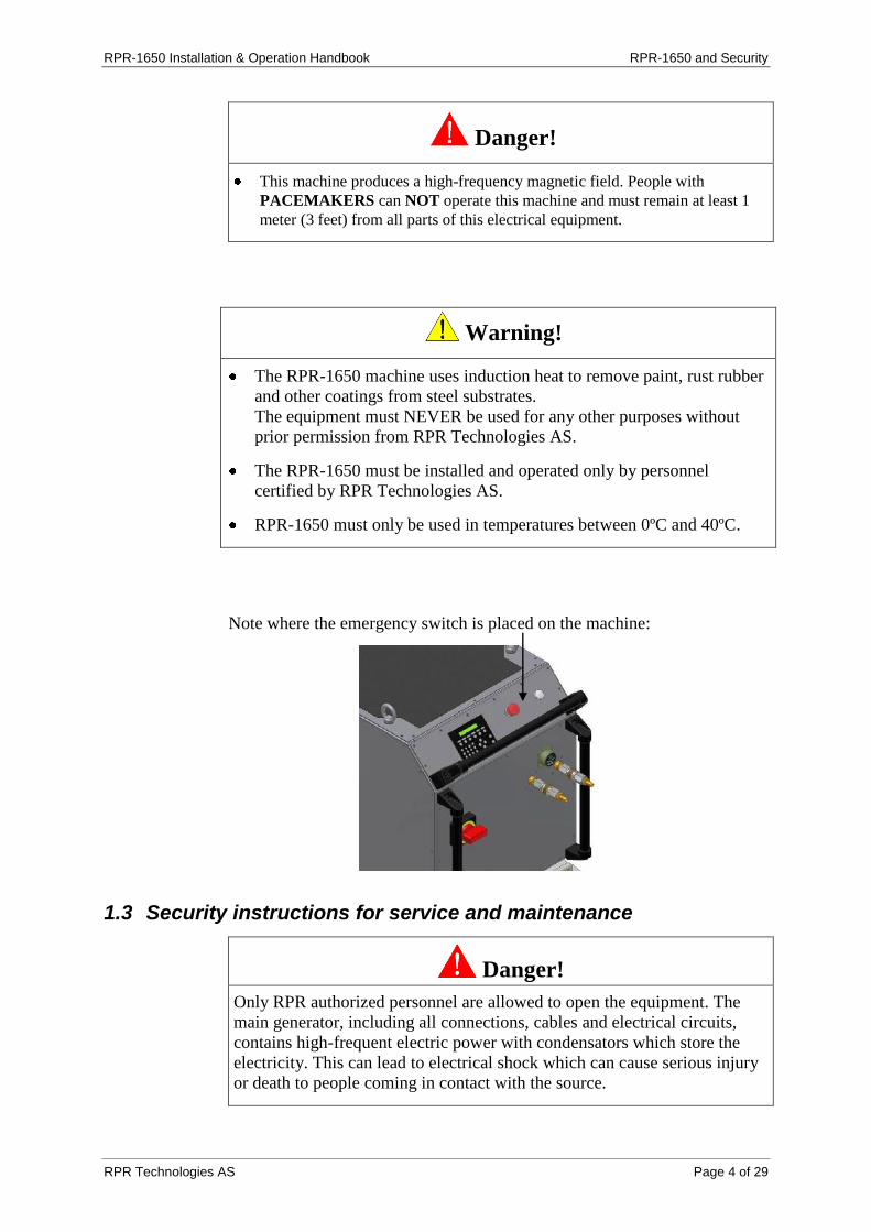
Note where the emergency switch is placed on the machine:
1.3 Security instructions for service and maintenance
Danger!
Only RPR authorized personnel are allowed to open the equipment. The
main generator, including all connections, cables and electrical circuits,
contains high-frequent electric power with condensators which store the
electricity. This can lead to electrical shock which can cause serious injury
or death to people coming in contact with the source.

RPR-1650 Installation & Operation Handbook RPR-1650 and Security
RPR Technologies AS Page 5 of 29
Installation of the main unit, maintenance and repair shall only be done
by persons certified by RPR Technologies AS. This includes any work
requiring opening the main generator or other equipment parts.
Operation, maintenance or repair of the RPR-1650 by personnel who are
not certified by RPR Technologies AS will void the equipment
guarantee. Any work done by non-certified personnel is undertaken at
your own risk.
All instructions in this handbook are guidelines for authorised personnel
only. The instructions and guidelines may be missing information. If in
doubt you should contact RPR Technologies AS for the relevant
information (contact details below).
1.4 Security instructions for service personnel authorized by RPR Technologies AS
When working on the main generator, always wait 90 seconds after
discharging the net power before touching anything inside the RPR-
1650 or any equipment connected to the generator. If there is a fault with
the RPR-1650 or any equipment connected to the generator, this waiting
time must be extended to at least 5 minutes.
The main generator shall under no circumstances be connected to the
electrical supply when there is work to be done inside the unit.
Before touching any components:
Measure the current (V), both AC and DC, between the component
and the metal housing (ground), with a voltmeter.
No measurements should be above 20 V before touching the
component.
Service/technical department RPR Technologies AS:
Phone: +47 35 60 35 38
E-mail: [email protected]
RPR-1650 Installation & Operation Handbook Unpacking the RPR-1650
RPR Technologies AS Page 6 of 29
2. Unpacking the RPR-1650
Warning!
To avoid damage to the equipment, find a flat area where you can unpack
the RPR-1650 safely and without danger of the equipment falling or being
scratched when removing the wrapping from the different parts.
When you receive your new RPR-1650, you do as follows:
1. Before opening the boxes and unpacking your RPR-1650, you must
check the boxes and pallets for outer damage. If you find any damage:
Describe the damage in writing.
Take pictures of the damage.
2. Do not destroy the boxes during unpacking. These can be re-used for
transporting the RPR-1650 later.
3. Open the boxes and unpack the RPR-1650 and unwrap all the cables and
different parts.
4. Check that all equipment and parts are free of damage and that they are
in agreement with the enclosed packing list. If you find any damage:
Describe the damage in writing.
Take pictures of the damage.
5. Do not start assembly or connection before all parts are safely stored.
6. Store all boxes and wrapping for use in the later transport of the RPR-
1650.
3. Storing the RPR-1650
The RPR-1650 must be stored in frost-free conditions, protected from rain
and heavy wind. Indoor storage is recommended.
After heavy use, the RPR-1650 will have water inside all parts of the
cooling system. This is the reason frost-free storage is required. If frost-free
storage is not possible, the whole cooling system must be emptied of water
by using dry air with temperature above freezing point. This must be
completed before any hoses or induction heads are dismantled.

RPR-1650 Installation & Operation Handbook Preparing the Working Site
RPR Technologies AS Page 7 of 29
4. Preparing the Working Site
Before assembling and connecting the RPR-1650, you should prepare the
working site.
4.1 Electricity input
RPR-1650 should normally have 3 phases + ground, 400 V,
125 ampere.
Use of RPR-1650 in countries other than Norway: The RPR-1650 is
built to tolerate electrical current from 360 V to 500 V. Output and
working speeds may vary from normal in other countries.
NOTICE: The transformer inside of the machine needs to be
reconnected to the same voltage as the main supply.
If you do not have the correct electrical connections at the working site,
then there is an adaptor for the RPR-1650 which can be connected to a
cable to fit the local variety.
4.2 Water connection
RPR-1650 needs fresh water for cooling, minimum 4 bars / max 9 bars
and 10 litres per minute.
Control the quality of the cooling water:
The water must be free from dirt and salt/chlorides as this can settle
inside the induction head causing problems.
If the quality of the cooling water is no sufficient, you should use a
standard filter.
To avoid to low water flow:
The RPR-1650 will show a cooling water flow alarm when there is
insufficient flow to operate safely, i.e. when using several cable
packages (total length above 20 m) or when there is a big difference
in height from the main unit to the working place.
If the alarm shows, use an external pump to obtain sufficient water
flow.

RPR-1650 Installation & Operation Handbook Preparing the Working Site
RPR Technologies AS Page 8 of 29
4.3 Confining the work area
Careful!
The RPR-1650 cables and hoses are not designed to be driven over by
rolling material or to carry the weight of heavy material. If there is high
activity in the working area, you should consider confining the working
area so that the equipment not will be harmed.
4.4 Work pattern procedure
Careful!
Overheating can cause damage to the steel of the treated surface and
eventually lead to damage of the coating on the opposite side.
Overheating can occur if, for example, you overlap your movements on the
treated surface too quickly, or by working in a wrong pattern. A method to
avoid this problem is to sketch a mowing pattern on the surface to be treated
before starting. Write a pattern on the surface to be treated which is a little
bit smaller than the width of the induction head:
When you remove the coating (See section 7 Removal of paint and coatings,
page 17), you drag the induction head over each second marked-up field.
This prevents the overheating on the edges. Then go back and take the other
marked-up fields when the steel temperature has returned to normal.
Induction head

RPR-1650 Installation & Operation Handbook How to Connect the RPR-1650
RPR Technologies AS Page 9 of 29
5. How to Connect the RPR-1650
Careful!
Follow the instructions for connecting the RPR-1650 as described in this
chapter to avoid damage on the equipment.
5.1 Overview of the connections
It is easy to connect the RPR-1650, but it is very important to follow some
simple rules:
Do not connect the electricity or water supply to the RPR-1650 until
you have completed assembly of all cable packages, the condensator
box, the handheld transformer unit and the induction head.
All contacts are of the ”mil” type and have an internal track you must
get in the right position before entering the contact. Screw the locking
ring with the clock all the way in, and at the same time push the contact
in. This is to secure good contact on all contact pins.
Push the water hose connections hard together so that the locking ring
“clicks” back into the right position.
The maximum length of cable package between the main generator and
condensator box is 100 meters. Each cable package is 20 meters and has
connections on each end for connection to the main generator and the
condensator box. In total you can use five cable packages, and the length
of the total package can be 20, 40, 60, 80, or 100 meters.
Handheld transformer with Induction Head
Main Generator Condensator
Box
Cable Pack, 5 m
One or several 20 m Cable Packages (maximum five)

RPR-1650 Installation & Operation Handbook How to Connect the RPR-1650
RPR Technologies AS Page 10 of 29
5.2 Assembly of the induction head on the handheld transformer
You choose the induction head based on the size of the work, the thickness
and type of coating and the shape of the surface to be treated. Included with
your new RPR-1650 there are two standard flat induction heads for treating
flat surfaces. You can order induction heads for almost any surface and
profile such as angles, pipes, studs, etc. Contact your local RPR
representative about this.
How to assemble the induction head:
1. Take out the four screws with washers which sit in the end of the
handheld transformer unit.
2. Screw the induction head tightly in place with a 6 mm Allen key:
Make sure that both O-rings are on place before mounting the
induction head.
The cooper must be clean and free from foreign objects one both
surfaces.
It is very important that all the washers are on the right place so that
the induction head is tightly secured and has good contact with the
handheld transformer unit.
Use the 6 mm Allen key and torque the screws by hand. Do not
tighten too hard using extra equipment for this.
2. Assembling the white cable for the speed sensor:
Carefully pull the white cable with the sensor out from the handheld
transformer unit.
Carefully push the cable into the track on the induction head.
Carefully tighten the screws which hold the sensor.
The completely assembled induction head should look like this:
Dismantling should be done in opposite direction.

RPR-1650 Installation & Operation Handbook How to Connect the RPR-1650
RPR Technologies AS Page 11 of 29
Then place the cover over the connection bolts on the induction head.
Notice: The sensor cannot lie behind the cover. The Magnetic field will
then damage the sensor. It needs to be mounted

RPR-1650 Installation & Operation Handbook How to Connect the RPR-1650
RPR Technologies AS Page 12 of 29
5.3 Connection of hose package(s) between main generator and condensator box
A single hose package is 20 meters in length and has couplings on both ends
for connection to the main generator and the condensator box. Dependant on
your requirements, you can connect up to five hose packages so the total
length can be 20, 40, 60, 80, or 100 meters.
The connections are the same on the main-generator, the condensator box
and between each of the hose packages. The pictures below show the
connections consisting of two water connections and one electrical contact:
Finished connectors:
Handheld transformer with Induction Head
Main Generator Condensator
Box
Connection of one or several 20 m Cable Packages (maximum five)
RPR-1650 Installation & Operation Handbook How to Connect the RPR-1650
RPR Technologies AS Page 13 of 29
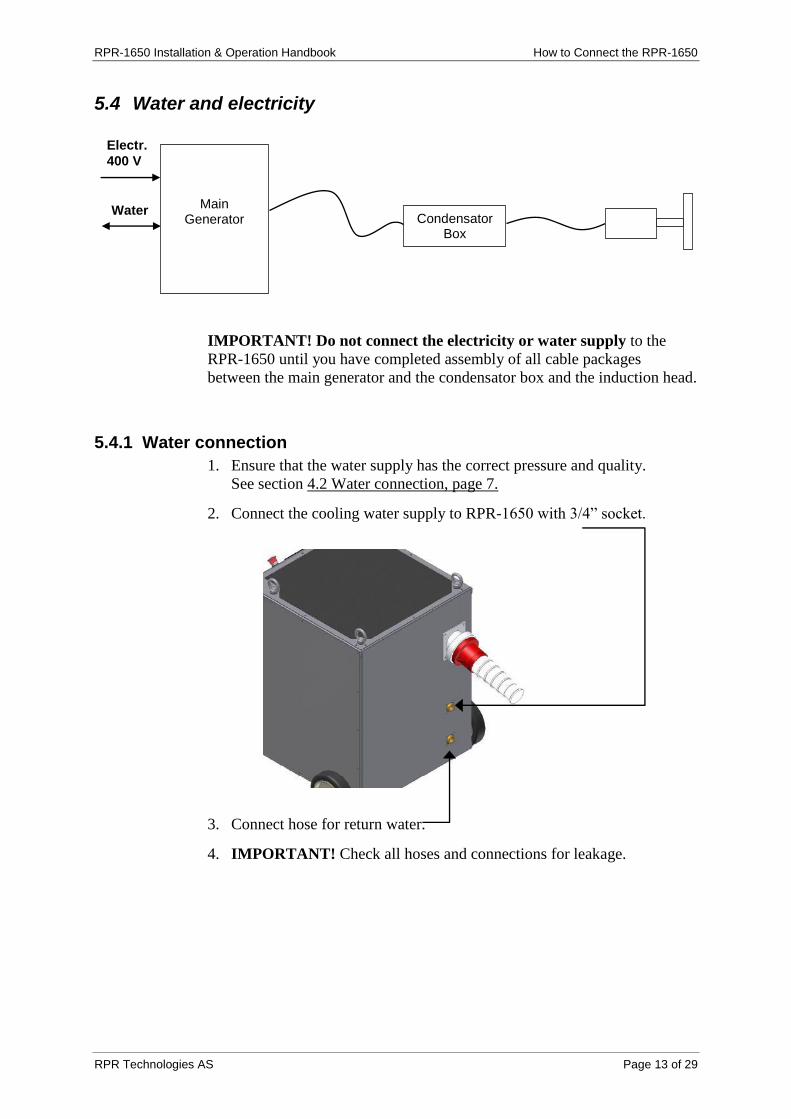
5.4 Water and electricity
IMPORTANT! Do not connect the electricity or water supply to the
RPR-1650 until you have completed assembly of all cable packages
between the main generator and the condensator box and the induction head.
5.4.1 Water connection
1. Ensure that the water supply has the correct pressure and quality.
See section 4.2 Water connection, page 7.
2. Connect the cooling water supply to RPR-1650 with 3/4” socket.
3. Connect hose for return water.
4. IMPORTANT! Check all hoses and connections for leakage.
Electr.
400 V
Water
Main Generator Condensator
Box

RPR-1650 Installation & Operation Handbook How to Connect the RPR-1650
RPR Technologies AS Page 14 of 29
5.4.2 Electricity connection
1. Ensure that the electricity supply has the correct parameters.
See section 4.1 Electricity input, page 7.
2. The main switch shall be in position OFF.
3. Connect the cable.
4. Turn the main switch to position ON.
Now you are ready to set the parameters for using the RPR-1650.
See next section.

RPR-1650 Installation & Operation Handbook Setting Parameters for Use of the RPR-1650
RPR Technologies AS Page 15 of 29
6. Setting Parameters for Use of the RPR-1650
Before you start to remove paint and coatings, you must set the correct
parameters for the desired result and progress. These parameters are
dependent on the size of the inductor head and the type and thickness of the
coating that is to be removed from the steel surface. There are two types of
program that you can choose. One for thin coatings that will come of easily,
and one for difficult and thick coatings. See sections 6.1 program 1 and 6.2
program 2.
A PLC-unit in the main generator controls the output in the induction head,
dependant of the speed with which you move the induction head across the
surface. The speed is measured with this sensor:
6.1 Program 1: Normal easy thin coatings
You must set the speed limit area with which you will move the induction
head for removal of paint and coating. (meter/minute):
1. Choose Auto
2. Choose speed: Start with setting SPEED = 5 (look at illustration on page
18) which is the lowest energy input per square millimetre. You should
avoid to overheating the steel.
3. Test the speed by moving the induction head over a limited area of the
coating and check if the coating is loose.
Always make the test on a new spot so you don’t heat the same area
twice. (If you do the test incorrectly, you can damage the steel or the
coating on opposite side!).
Take the SPEED setting down one step down at a time, until the
effect causes the coating to become loose.
4. After setting the speed you have to wait to remove the coating in the test
areas until the area is cooled down. (See section 4.4 Work pattern
procedures, page 8)

RPR-1650 Installation & Operation Handbook Setting Parameters for Use of the RPR-1650
RPR Technologies AS Page 16 of 29
5. Setting the maximum power: You only use this if you want to reduce the
maximum power on the induction head, i.e. you are removing a coating
on small areas, have a small induction head, or difficulties with the
surroundings. You can make the adjustment by using the POWER
button in relation to the specifications in Appendix1 on page 23.
6.2 Program 2: Difficult thick coating.
1. Choose Auto
2. Login by F5 button. Choose the menu “LOWER LIMITS”. In this menu
answer the question “ACTIVATE LOWER” with “YES”.
3. Start with POSITION 1= 40% (start point of voltage output) by pushing the
F4 button. Start with setting SPEED = 5 by pushing the F1 button.
4. Test the POSITION setting by moving the induction head over a limited
area of the coating and check if the coating is loose.
a. Always make the test on a new spot so you don’t heat the same area
twice. (If you do the test incorrectly, you can damage the steel or
the coating on opposite side!).
b. Take the POSITION setting up one step at a time, until the effect
causes the coating to become loose.
c. If the coating still doesn’t become loose you need to take the
SPEED setting down one step down at a time, until the effect causes
the coating to become loose.
5. After setting the speed you have to wait to remove the coating in the test
areas until the area is cooled down. (See section 4.4 Work pattern
procedures, page 8)
6. In this program the power setting will always be 100%, see appendix 2 on
page 24

RPR-1650 Installation & Operation Handbook Setting Parameters for Use of the RPR-1650
RPR Technologies AS Page 17 of 29
Speed limit area Reset LCD-display Start value voltage Maximum power setting
Manual/Automatic Login Up/Down Enter
Description of the buttons:
SPEED (Speed limit area): This has five preset maximum speeds. This
will indicate how you should set the speed based on the type of coating and
the size of the induction head. This means that you have an interval on the
setting, i.e. 10 meter/minute which ensure that the RPR-1650 gives the
needed power output based on the speed between 0 meter/minute to max
power when at 10 meter/minute. See Appendix 1 on page 23 for settings.
MAN/AUTO: With this button you can set whether you want to use the
RPR-1650 with or without the power adjustment based on speed. You often
use the manual setting when the coating is very thick (above 12 mm) and on
small working pieces. IMPORTANT! On the manual setting there is a
danger of overheating the steel or damage to the coating on opposite side.
RESET: If there is a warning in the display, the machine will trip. This
button can be used for resetting the machine and removing the warning
message in the display. If the warning is repeated after pushing reset, look at
checklist in Appendix 2 or contact your RPR distributor.
POWER: In some cases there is a need to use less than full power on the
induction head, i.e. on small areas or with a small induction head or in
difficult surroundings. This adjustment can be made with this button based
on the specification in Appendix 1 on page 23.
LCD-display: This displays all settings and warning codes for the RPR-
1650, including power output and speed when in use. For warning codes see
section 9. Check-List if the Machine Stops, page 19.
Up/down and Enter: These buttons should only be used by authorised
personnel (coded) for changing parameters on the RPR-1650.

RPR-1650 Installation & Operation Handbook Removal of Paint and Coatings
RPR Technologies AS Page 18 of 29
7. Removal of Paint and Coatings
Careful!
It is very important that the steel is not overheated. This can happen if you
move the induction head over the same area twice without time in between
for the steel to be cooled down. Overheating can damage the steel or the
coating on opposite side.
1. See that the following are done correctly:
Preparation: See section 4. Preparing the Working Site, page 7,
Connections: See section 5. How to Connect the RPR-1650, page 9.
Setting of Parameters: See section 6. Setting Parameters, page 15.
2. Check all hoses, cables and connections for leakage or damage. The
LCD-display on the main generator will give warning messages and the
RPR-1650 will stop when there is something wrong, but do the check
anyway.
3. Use the sketched working pattern (See section 4.4 Work pattern
procedure, page 8) and drag the induction head over every second
marked field so the steel not is overheated on the overlapping edges.
4. Sometimes the coating will not be loose enough to take away by hand,
dependant on the generic type of coating and the age of the coating.
When this occurs you should use a suitable scraper to remove the
coating.
5. When every second marked field is finished you should go back and
treat the fields in between. Ensure that the steel temperature is back to
normal before doing this.
8. Transporting the RPR-1650
The RPR-1650 is easy to move with a forklift, crane or by rolling on its own
wheels. For longer transport and change of working site, we recommend
that you dismantle the cables, contacts and induction head.
Before longer transport, you should pack the RPR-1650 into the boxes as
the machine was when it was new. The RPR-1650 does tolerate changes in
weather and light bumps and shaking, but it is important that the machine
does not get big bumps or heavy outer loads.
If you don’t have the original boxes, pack the RPR-1650 to ensure it is well
protected and stabilized.

RPR-1650 Installation & Operation Handbook Check-List if the Machine Stops
RPR Technologies AS Page 19 of 29
9. Check-List if the Machine Stops
The following warning codes can appear on the display on the main
generator. If the codes don’t disappear when pushing button RESET, do the
following:
Trip: One or several of the generator control systems for power, current
and/or frequency is outside the generator’s limits. If this problem persists
after pushing reset, it should only be handled by authorized personnel.
Cooling Water Fault:
Check for leakage or damage to hoses.
Cooling water flow is too low, install a pump for extra pressure.
The equipment you are using can’t deliver enough water flow.
Check the hoses, maybe they are too small.
Temperature Fault: The temperature of the cooling water or ambient
temperature is too high. Colder cooling water will solve the problem (The
generator trips at 37ºC).
RPH: The phases on main electricity input are wrong. You must switch the
phases.

RPR-1650 Installation & Operation Handbook Service and Maintenance
RPR Technologies AS Page 20 of 29
10. Service and Maintenance
10.1 Daily control of hoses, cables and connections
Warning!
Every morning and before starting work with the RPR-1650 you should
check all hoses, cables and connections for any leakage or damage. Do not
use the equipment before damage is repaired.
10.2 Daily cleaning of RPR-1650
Danger!
Disconnect the electricity to RPR-1650 before the cleaning starts. The main
generator, including all connections, cables and electrical circuits, contains
high-frequent electric power with condensators which store the electricity.
This can lead to electrical shock which can cause serious injury or death to
people coming in contact with the source.
Wash the equipment daily with lukewarm water and a soft detergent.
DO NOT use high-pressure washing!
Clean the wheels on the induction-head daily, both the track and the
indicator tracks for the PLC-sensor. Scrape off remains of coating or
paint and wash with lukewarm water and soft detergent
Track Indicator-tracks on the inside
Clean the induction head with a stiff brush (not a steel brush) and
lukewarm water and soft detergent.
For service, repair and maintenance, contact your local RPR-dealer or RPR Technologies AS

RPR-1650 Installation & Operation Handbook Dealers and Servicing
RPR Technologies AS Page 21 of 29
11. Dealers and Servicing
Norway:
RPR Technologies
Rolighetsvegen 7c, 3933 Porsgrunn, Norway
Phone: +47 35 60 35 38
Fax: +47 67 43 00 57
Web: http://www.rprtec.com
Norspray AS
Contact: Roar Bråtane
Address: Gamle Forusvei 14c, 4033 Stavanger, Norway
Phone: +47 51 22 07 01
Fax: + 47 51 59 18 90
Web: http://www.norspray.no
USA:
Keizer Technologies, Inc
North American Sales
Contact: Judd Adcock
Address: 10908 South Pipeline Road, Euless, Texas 76040, USA
Phone: Tel: +01 817 685 7090
Fax: +01 817 685 9190
Web: http://www.torbousa.com
Peru/Chile
Consultores Marinos SAC
Av. Los Halcones 424, Lima-34, Peru
Tel: +511 99 834 2483
Contact: Javier A. Calmet Aranguren
France:
Plastocor-france S.A.S.
21, En Chaplerue, F-57000 Metz, France
Tel: +33 (0) 67 360 67 12
Fax: +33 (0) 38 779 46 86
Contact: Hubert Barth
German, BeNeLux and Austrian Sales
Oftec GmbH
Barbarastrasse 75-77, D-46282 Dorsten, Germany
Tel: +49 (0) 209 9592 144
Contact: Mr. Christian Streck

RPR-1650 Installation & Operation Handbook Dealers and Servicing
RPR Technologies AS Page 22 of 29
Spain:
Salvio Busquets, S.A.
75-77, Les Corts, 10, 08249 Cabrera de Mar, Barcelona
Tel: +34 629 711 346
Contact: Mr. Alfred Busquets
Japan:
e-Energy Corporation
7-19, Akasaka 1-chome, Minato-ku, Tokyo 107-0052, Japan
Tel: +81 3 5549 7771
Fax: +81 3 5549 7774
Contact: Wataru Nammoku
South Korea:
Mrs Kyung-Ja Kim
1150 German Village, Mulgeon-ri, Samdong-myeon, Namhae-gun,
Kyeong-nam (668-841), South-Korea
Tel: +82 (0)55 867 1180
Fax: +82 (0)10 4621 5099
Contact: Mrs Kyung-Ja Kim
Taiwan:
TGC Technology Ltd
6th Fl., 267 Tun Hwa South Road, Sec. 2 Taipei 10675, Taiwan
Tel: +886 2 2378 9331
Fax: +886 2 2378 8667
Contact: Carol Chen
Vietnam:
Vinashin Petrolium Investment & Transport
Unit 210-211, 02nd Floor, Petro Vietnam Tower, No. 1-5 Le Duan Str,
Ben Nghe Ward, District 1, Ho Chi Minh City, Vietnam
Tel: +84 839 300 704
Fax: +84 839 300 706
Contact: Mr. Phan Minh Dung

Appendix 1: RPR-1650 Voltage Output / Speed Program 1

Appendix 2: RPR-1650 Voltage Output / Speed Program 2

RPR-1650 Installation & Operation Handbook Appendix 3: Service Log
RPR Technologies AS Side 25 of 29
Appendix 3: Service Log
Make notes on service and maintenance performed on the RPR-1650.
Date Tasks Done by Comments
If you need more service log diagrams, please contact your RPR-1650 dealer.