Embed Size (px)
Citation preview

J.L. Van NoordGlenn Research Center, Cleveland, Ohio
B.R. StiegemeierASRC Aerospace Corporation, Cleveland, Ohio
RP–2 Thermal Stability and Heat Transfer Investigation for Hydrocarbon Boost Engines
NASA/TM—2010-216917
November 2010
https://ntrs.nasa.gov/search.jsp?R=20110000532 2020-04-03T03:32:53+00:00Z

NASA STI Program . . . in Profi le
Since its founding, NASA has been dedicated to the advancement of aeronautics and space science. The NASA Scientifi c and Technical Information (STI) program plays a key part in helping NASA maintain this important role.
The NASA STI Program operates under the auspices of the Agency Chief Information Offi cer. It collects, organizes, provides for archiving, and disseminates NASA’s STI. The NASA STI program provides access to the NASA Aeronautics and Space Database and its public interface, the NASA Technical Reports Server, thus providing one of the largest collections of aeronautical and space science STI in the world. Results are published in both non-NASA channels and by NASA in the NASA STI Report Series, which includes the following report types: • TECHNICAL PUBLICATION. Reports of
completed research or a major signifi cant phase of research that present the results of NASA programs and include extensive data or theoretical analysis. Includes compilations of signifi cant scientifi c and technical data and information deemed to be of continuing reference value. NASA counterpart of peer-reviewed formal professional papers but has less stringent limitations on manuscript length and extent of graphic presentations.
• TECHNICAL MEMORANDUM. Scientifi c
and technical fi ndings that are preliminary or of specialized interest, e.g., quick release reports, working papers, and bibliographies that contain minimal annotation. Does not contain extensive analysis.
• CONTRACTOR REPORT. Scientifi c and
technical fi ndings by NASA-sponsored contractors and grantees.
• CONFERENCE PUBLICATION. Collected papers from scientifi c and technical conferences, symposia, seminars, or other meetings sponsored or cosponsored by NASA.
• SPECIAL PUBLICATION. Scientifi c,
technical, or historical information from NASA programs, projects, and missions, often concerned with subjects having substantial public interest.
• TECHNICAL TRANSLATION. English-
language translations of foreign scientifi c and technical material pertinent to NASA’s mission.
Specialized services also include creating custom thesauri, building customized databases, organizing and publishing research results.
For more information about the NASA STI program, see the following:
• Access the NASA STI program home page at http://www.sti.nasa.gov
• E-mail your question via the Internet to help@
sti.nasa.gov • Fax your question to the NASA STI Help Desk
at 443–757–5803 • Telephone the NASA STI Help Desk at 443–757–5802 • Write to:
NASA Center for AeroSpace Information (CASI) 7115 Standard Drive Hanover, MD 21076–1320

J.L. Van NoordGlenn Research Center, Cleveland, Ohio
B.R. StiegemeierASRC Aerospace Corporation, Cleveland, Ohio
RP–2 Thermal Stability and Heat Transfer Investigation for Hydrocarbon Boost Engines
NASA/TM—2010-216917
November 2010
National Aeronautics andSpace Administration
Glenn Research CenterCleveland, Ohio 44135
Prepared for the57th Joint Army-Navy-NASA-Air Force (JANNAF) Propulsion Meeting sponsored by the JANNAF Interagency Propulsion CommitteeColorado Springs, Colorado, May 3–7, 2010
Acknowledgments
The authors would like to thank Mr. Matt Billingsley of AFRL for funding this work and his support during the test program. Further thanks go to the staff of the NASA Glenn Research Center
for preparing the test facility and conducting the experiments.
Available from
NASA Center for Aerospace Information7115 Standard DriveHanover, MD 21076–1320
National Technical Information Service5301 Shawnee Road
Alexandria, VA 22312
Available electronically at http://gltrs.grc.nasa.gov
Level of Review: This material has been technically reviewed by technical management.

NASA/TM—2010-216917 1
RP–2 Thermal Stability and Heat Transfer Investigation for Hydrocarbon Boost Engines
J.L. Van Noord
National Aeronautics and Space Administration Glenn Research Center Cleveland, Ohio 44135
B.R. Stiegemeier
ASRC Aerospace Corporation Cleveland, Ohio 44135
Abstract A series of electrically heated tube tests were performed at the NASA Glenn Research Center’s
Heated Tube Facility to investigate the use of RP-2 as a fuel for next generation regeneratively cooled hydrocarbon boost engines. The effect that test duration, operating condition and test piece material have on the overall thermal stability and materials compatibility characteristics of RP-2 were evaluated using copper and 304 stainless steel test sections. The copper tests were run at 1000 psia, heat flux up to 6.0 Btu/in.2-sec, and wall temperatures up to 1180 °F. Preliminary results, using measured wall temperature as an indirect indicator of the carbon deposition process, show that in copper test pieces above approximately 850 °F, RP-2 begins to undergo thermal decomposition resulting in local carbon deposits. Wall temperature traces show significant local temperature increases followed by near instantaneous drops which have been attributed to the carbon deposition/shedding process in previous investigations. Data reduction is currently underway for the stainless steel test sections and carbon deposition measurements will be performed in the future for all test sections used in this investigation. In conjunction with the existing thermal stability database, these findings give insight into the feasibility of cooling a long life, high performance, high-pressure liquid rocket combustor and nozzle with RP-2.
Introduction Experience has shown that hydrocarbon fuels at sufficiently high temperatures begin to decompose
resulting in the formation of gums and solids that can deposit on wetted fuel surfaces. The deposit then acts as an insulating layer, causing a further increase in wall temperature, which can eventually lead to loss of structural integrity and propulsion system failure. Excessive deposits may also reduce the coolant flow area and increase surface roughness resulting in increased coolant pressure drop or reduced coolant flow rate. The rate at which the deposition process occurs is driven by many factors such as wall temperature, fuel composition (e.g., sulfur and oxygen content), velocity (residence time), and coolant passage material. At the present time, the interaction of these effects is not completely understood and the prediction of deposition remains difficult. However, it is generally accepted that at lower temperatures, less than about 900 °F, the deposition process occurs as the result of auto-oxidation reactions, whereas the deposition process at higher temperatures is driven by the pyrolysis of the hydrocarbon molecules (Ref. 1).
An additional complication has also been reported for hydrocarbon fuels containing fuel-bound sulfur components when they are used to cool copper and copper alloy structures. The sulfur reacts with the copper to form copper sulfides. This sulfide corrosion can both damage the copper surface and disturb the flow. In References 2 to 5, which contain heated tube test results performed under rocket engine conditions, dendritic structures were observed protruding from copper or copper alloy surfaces. Analysis indicated that these dendrites were composed largely of copper and were also referred to as “copper wool.” In experiments reported in reference 4, the possibility that the dendritic structures were caused by reaction of the fuel-bound sulfur with the copper in the test section surface was investigated by doping

NASA/TM—2010-216917 2
fuels (RP-1, methane, propane) with additional sulfur compounds (thianaphthene, benzyl disulfide), and indeed an increase in the dendritic formations was observed after increasing the fuel sulfur content. In addition, the dendrite formations were identified as copper sulfides.
For advanced hydrocarbon rocket engines, preliminary data suggest that the kerosene fuel RP-2 may offer significant advantages with regard to both carbonaceous and cuprous sulfide formation as compared to the traditional kerosene rocket propellant RP-1. However, currently available data are limited and no parametric studies have been undertaken to clearly define the operating environment into which RP-2 can be confidently implemented. In an effort to help delineate this operational environment, a series of heated tube experiments was conducted at the NASA Glenn Research Center Heated Tube Facility with RP-2, using both copper and 304 stainless steel test sections, at different operating conditions. Emphasis in this paper is placed on the preliminary results obtained using copper test pieces as data reduction is currently underway for tests run in this investigation using 304 stainless steel test sections. Furthermore, carbon deposition measurements will be for all test sections used in this investigation to quantify any carbon deposits that were produced during testing.
Facility and Hardware
Tests were conducted in the NASA Glenn Research Center Heated Tube Facility (HTF). This facility was developed for simulating the heat flux conditions of a regeneratively cooled liquid rocket engine combustion chamber and is described in Reference 6. HTF uses resistively heated test sections to simulate the cooling channel environment for a variety of propulsion systems. Test section geometries in past investigations have included rectangular cross-section, curved test sections to simulate the nozzle of a typical rocket engine, and straight circular cross-section test sections fabricated from drawn tubing (Ref. 7). For this investigation, the HTF produces a symmetric, near constant heat flux boundary condition at the test section wall. The near constant heat flux condition allows axial wall temperature gradients to develop along the test section as the fluid temperature increases and the cooling capacity decreases. All experiments conducted at the HTF for this investigation used the combustible liquid flow system. A simplified schematic of the facility architecture is shown in Figure 1 (Ref. 2).
Figure 1.—Simplified schematic of the NASA Glenn Heated Tube Facility (Ref. 2).

NASA/TM—2010-216917 3
Flow rate and test section pressure are regulated by setting the nitrogen pressure in the supply tank to the desired level and then activating a control system that utilizes a Coriolis flow meter and two control valves (one back pressure and the other flow control) to continually maintain the desired test section flow and pressure conditions. The fuel, upon leaving the test section, is cooled using a water heat exchanger and is then stored in a scrap tank that is vented to the atmosphere. Electrical power is supplied to the test section from up to four 80 VDC, 1500 A welding power supplies. Further details on this facility, details concerning run procedures, and details concerning data reduction methodology can be found in Reference 6.
All test sections utilized in this investigation were fabricated from drawn pure copper (C101) or 304 stainless steel tubing with an OD of 0.125 in. and an ID of 0.061 in. Surface roughness measurements were previously performed on several as delivered copper tube lengths and an average value was determined to be approximately 15 μin. Wall temperature measurements were made with 10 K-type thermocouples attached to the outer surface of the tube at various axial stations. The thermocouples were torch brazed to the copper test pieces and spot welded to the 304 stainless steel test pieces. Reference 1 discusses the induced temperature error caused by voltage in the tube and the method to correct for it. A length of 6.0 in. (L/D >100) was provided before the start of the heated section to allow for flow development. Rectangular copper bus bars (1- by 3- by 0.25 in.) were brazed to the tube to provide electrical coupling to the power supplies. Typical test piece geometry is shown in Figure 2.
As the primary goal of this investigation was to attempt to evaluate a “coking temperature” for RP-2 and compare the response for different materials, it was decided to conduct a series of experiments varying wall temperature while keeping all other test section parameters nominally constant. It was hoped that as wall temperature values were increased in successive tests, a threshold value for wetted wall temperature would be reached, above which local carbon deposition would begin to increase dramatically. The temperature at which this occurs is traditionally termed the “coking temperature.”
Although the objectives for this study were focused toward advanced high-pressure rocket engines, parametric coking data for RP-1 conducted at high pressures is sparse in the literature. With this in mind, it was decided to conduct the experiments performed at the HTF at an average test section pressure near 1000 psia. Although this pressure is lower than values representative of high pressure rocket engines, it does allow comparison to a significant amount of data that has been collected for RP-1, ultra-low sulfur RP-1, and a variety of other hydrocarbon fuels over the years. This working pressure would also allow a comparison to be made between the historical rule of thumb coking limit developed for RP-1 and that hoped to be determined for RP-2. It should be noted that the 1000 psia working pressure was chosen in past investigations to represent a pressure level close to that encountered in the cooling channels of current operational RP-1 engines such as the RS-27A and MA-5A.
NASA Glenn Heated Tube Facility
Figure 2.—Experimental test section configuration for thermal stability testing (Ref. 8).
NASA/TM—2010-216917 4
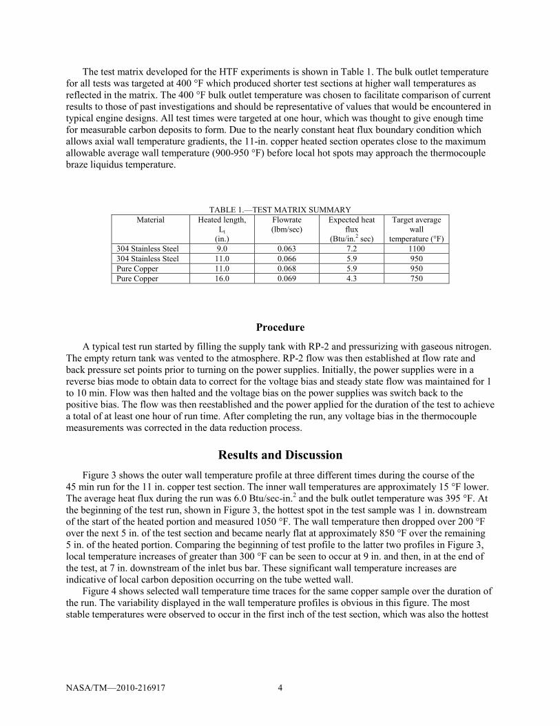
The test matrix developed for the HTF experiments is shown in Table 1. The bulk outlet temperature for all tests was targeted at 400 °F which produced shorter test sections at higher wall temperatures as reflected in the matrix. The 400 °F bulk outlet temperature was chosen to facilitate comparison of current results to those of past investigations and should be representative of values that would be encountered in typical engine designs. All test times were targeted at one hour, which was thought to give enough time for measurable carbon deposits to form. Due to the nearly constant heat flux boundary condition which allows axial wall temperature gradients, the 11-in. copper heated section operates close to the maximum allowable average wall temperature (900-950 °F) before local hot spots may approach the thermocouple braze liquidus temperature.
TABLE 1.—TEST MATRIX SUMMARY Material Heated length,
Lt (in.)
Flowrate (lbm/sec)
Expected heat flux
(Btu/in.2 sec)
Target average wall
temperature (°F) 304 Stainless Steel 9.0 0.063 7.2 1100 304 Stainless Steel 11.0 0.066 5.9 950 Pure Copper 11.0 0.068 5.9 950 Pure Copper 16.0 0.069 4.3 750
Procedure
A typical test run started by filling the supply tank with RP-2 and pressurizing with gaseous nitrogen. The empty return tank was vented to the atmosphere. RP-2 flow was then established at flow rate and back pressure set points prior to turning on the power supplies. Initially, the power supplies were in a reverse bias mode to obtain data to correct for the voltage bias and steady state flow was maintained for 1 to 10 min. Flow was then halted and the voltage bias on the power supplies was switch back to the positive bias. The flow was then reestablished and the power applied for the duration of the test to achieve a total of at least one hour of run time. After completing the run, any voltage bias in the thermocouple measurements was corrected in the data reduction process.
Results and Discussion Figure 3 shows the outer wall temperature profile at three different times during the course of the
45 min run for the 11 in. copper test section. The inner wall temperatures are approximately 15 °F lower. The average heat flux during the run was 6.0 Btu/sec-in.2 and the bulk outlet temperature was 395 °F. At the beginning of the test run, shown in Figure 3, the hottest spot in the test sample was 1 in. downstream of the start of the heated portion and measured 1050 °F. The wall temperature then dropped over 200 °F over the next 5 in. of the test section and became nearly flat at approximately 850 °F over the remaining 5 in. of the heated portion. Comparing the beginning of test profile to the latter two profiles in Figure 3, local temperature increases of greater than 300 °F can be seen to occur at 9 in. and then, in at the end of the test, at 7 in. downstream of the inlet bus bar. These significant wall temperature increases are indicative of local carbon deposition occurring on the tube wetted wall.
Figure 4 shows selected wall temperature time traces for the same copper sample over the duration of the run. The variability displayed in the wall temperature profiles is obvious in this figure. The most stable temperatures were observed to occur in the first inch of the test section, which was also the hottest

NASA/TM—2010-216917 5
Figure 3.—Eleven inch heated copper sample temperature profile at three times during
the test run.
Figure 4.—Select temperature time histories for the 11-in. heated copper sample.

NASA/TM—2010-216917 6
portion of the test section. The average temperature here barely changes over the course of the run. At 2 in. from the entrance of the heated portion, the wall temperature actually decreases 100 °F over the duration of testing. The other thermocouple time histories shown in the figure, taken further downstream in the test section, display significant increases followed by almost instantaneous drops in local wall temperature. In previous investigations this has been attributed to carbon deposit build-up and then shedding, which would significantly change the local heat transfer rates and resulting wall temperatures. The localized hot spots observed in the data were also confirmed visually as bright spots on the video monitoring equipment. Due to the significant wall temperature variation seen over the course of the run, the test was stopped prematurely at 45 min instead of the planned hour.
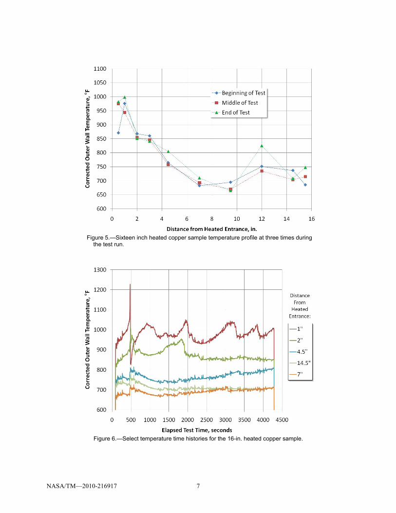
Figure 5 shows the outer wall temperature profile for the 16 in. copper sample at three different times during the course of the run. For this test piece the inner wall temperatures were about 10 °F lower than those measured on the tube outer surface. This sample was designed to have lower wall temperatures than the 11 in. test piece and was run with an average heat flux of 4.4 Btu/in.2 sec, resulting in an average outlet bulk fluid temperature of 395 °F. Although the wall temperatures were cooler than the 11 in. sample, the wall temperature profile was similar to that shorter test piece. At the beginning of the test, the hottest temperature in the profile was 1 in. downstream of the heated portion entrance at 975 °F. The temperature then dropped about 300 °F over the next 6 in., showed a rise of about 70 °F over the next 5 in. downstream, and finally dipped at the last thermocouple to 685 °F. The profiles do show some variation at different time slices with individual thermocouples indicating a local change of up to 100 °F, but the general trend of hotter wall temperatures near the entrance and cooler wall temperatures toward the exit is maintained. Figure 6 shows selected temperature time histories for the test section taken over the duration of the run. Local temperatures can be seen to increase on the order of 100 °F and then suddenly drop indicating potential carbon deposition followed by deposit shedding.
Comparing Figure 4 and Figure 6, it can be seen that when local wall temperatures are higher than about 850 °F almost every thermocouple showed indications of capturing carbon deposition/shedding events. The notable exception was the first thermocouple on the 11 in. test section that remained very steady over 1000 °F during the entire 45 min run. These results are consistent with previous investigations that have also tended to place 850 °F as an approximate ‘coking temperature’ for RP-2.
Figure 7 shows a video still taken of the 11-in. copper (6.0 Btu/in.2 sec) test piece during the run and confirms the local hot spots seen in the data. The intensity of the hot spots correlated well with the local measured wall temperatures. Also noted on the figure, as open circles, are approximate thermocouple locations. The hot spots, which did not change location during the course of the run, appeared to be located where the thermocouples were attached. Between the thermocouples the wall temperature significantly drops and does not appear to glow on the image. As the thermocouple torch brazing process was performed with the test section open to the atmosphere, it could be possible that attaching the thermocouples lead to local oxidation or other surface chemistry changes on the inside surface of the test section. These changes would occur around the thermocouples where the energy from the torch was directed. The effect that this could have on the deposition process, if it occurred, is unknown, but should be investigated in future test programs.
NASA/TM—2010-216917 7
Figure 5.—Sixteen inch heated copper sample temperature profile at three times during
the test run.
Figure 6.—Select temperature time histories for the 16-in. heated copper sample.

NASA/TM—2010-216917 8
Figure 7.—Video image of the 11 in. copper test piece showing local
hot spots and approximate thermocouple locations.

NASA/TM—2010-216917 9
Summary and Conclusions A series of heated tube experiments was conducted at the NASA Glenn Research Center Heated Tube
Facility with RP-2 using both copper and 304 stainless steel test sections. Tests were performed at different operating conditions in an attempt to gather data that could help delineate the operational environment into which RP-2 could be implemented without increased risk to hydrocarbon boost engine programs. Preliminary data for copper test sections, run at average heat fluxes of 4.4 and 6.0 Btu/in.2 sec, showed wall temperature rises as large as 300 °F followed by near instantaneous drops, indicating signs of carbon deposition/shedding processes occurring, when local average wall temperatures were greater than approximately 850 °F. It was also noted from video images that these local hot spots seemed only to occur around thermocouples and not between them where wall temperatures remained much cooler. This could indicate that the thermocouple attachment method contributed to the wall temperature behavior. Further work continues to analyze the data and collect coking information for the test pieces.
References 1. Katta, V.R., Jones, E.G., and Roquemore, W.M., “Modeling of Deposition Process in Liquid Fuels,”
Combust. Sci. and Tech, Vol. 139, pp. 75–111, 1998. 2. Stiegemeier, B., Meyer, M. L., and Taghavi, R., “Thermal Stability and Heat Transfer Characteristics
of Five Hydrocarbon Fuels: JP-7, JP-8, JP-8+100, JP-10, and RP-1,” AIAA–2002–3873, 2002. 3. Giovanetti, A.J., Spadaccini, L.J., and Szetela, E.J., “Deposit Formation and Heat Transfer in
Hydrocarbon Rocket Fuels,” NASA CR–168277, Oct. 1983. 4. Roback, R., Spadaccini, L.J., and Szetela, E.J., “Deposit Formation in Hydrocarbon Rocket Fuels,”
NASA CR–165405, Aug. 1981. 5. Homer, D.G., and Rosenberg, S.D., “Hydrocarbon Fuel/Combustion-Chamber-Liner Materials
Compatibility,” NASA CR–187104, Apr. 1991. 6. Green, J. M., Pease, G. M., and Meyer, M. L., “A Heated Tube Facility for Rocket Coolant Channel
Research,” AIAA–95–2936, 1995. 7. Meyer, M.L., “Electrically Heated Tube Investigation of Cooling Channel Geometry Effects,”
AIAA–95–2500, NASA TM–106985, 1995. 8. Billingsly, M.C. and Stiegemeier, B.R. “RP-2 Deposit Formation at High Wall Temperature in Two
Heated Tube Configurations”, Joint Army/Navy/NASA/Air Force (JANNAF) 6th Modeling and Simulation/4th Liquid Propulsion/3rd Spacecraft Propulsion Joint Subcommittee Meeting, Orlando, FL, Dec. 8–12, 2008.

REPORT DOCUMENTATION PAGE Form Approved
OMB No. 0704-0188 The public reporting burden for this collection of information is estimated to average 1 hour per response, including the time for reviewing instructions, searching existing data sources, gathering and maintaining the data needed, and completing and reviewing the collection of information. Send comments regarding this burden estimate or any other aspect of this collection of information, including suggestions for reducing this burden, to Department of Defense, Washington Headquarters Services, Directorate for Information Operations and Reports (0704-0188), 1215 Jefferson Davis Highway, Suite 1204, Arlington, VA 22202-4302. Respondents should be aware that notwithstanding any other provision of law, no person shall be subject to any penalty for failing to comply with a collection of information if it does not display a currently valid OMB control number. PLEASE DO NOT RETURN YOUR FORM TO THE ABOVE ADDRESS.
1. REPORT DATE (DD-MM-YYYY) 01-11-2010
2. REPORT TYPE Technical Memorandum
3. DATES COVERED (From - To)
4. TITLE AND SUBTITLE RP-2 Thermal Stability and Heat Transfer Investigation for Hydrocarbon Boost Engines
5a. CONTRACT NUMBER
5b. GRANT NUMBER
5c. PROGRAM ELEMENT NUMBER
6. AUTHOR(S) Van Noord, J., L.; Stiegemeier, B., R.
5d. PROJECT NUMBER
5e. TASK NUMBER
5f. WORK UNIT NUMBER WBS 253225.04.03.09.02.03
7. PERFORMING ORGANIZATION NAME(S) AND ADDRESS(ES) National Aeronautics and Space Administration John H. Glenn Research Center at Lewis Field Cleveland, Ohio 44135-3191
8. PERFORMING ORGANIZATION REPORT NUMBER E-17493
9. SPONSORING/MONITORING AGENCY NAME(S) AND ADDRESS(ES) National Aeronautics and Space Administration Washington, DC 20546-0001
10. SPONSORING/MONITOR'S ACRONYM(S) NASA
11. SPONSORING/MONITORING REPORT NUMBER NASA/TM-2010-216917
12. DISTRIBUTION/AVAILABILITY STATEMENT Unclassified-Unlimited Subject Category: 20 Available electronically at http://gltrs.grc.nasa.gov This publication is available from the NASA Center for AeroSpace Information, 443-757-5802
13. SUPPLEMENTARY NOTES
14. ABSTRACT A series of electrically heated tube tests were performed at the NASA Glenn Research Center’s Heated Tube Facility to investigate the use of RP-2 as a fuel for next generation regeneratively cooled hydrocarbon boost engines. The effect that test duration, operating condition and test piece material have on the overall thermal stability and materials compatibility characteristics of RP-2 were evaluated using copper and 304 stainless steel test sections. The copper tests were run at 1000 psia, heat flux up to 6.0 Btu/in.2-sec, and wall temperatures up to 1180 °F. Preliminary results, using measured wall temperature as an indirect indicator of the carbon deposition process, show that in copper test pieces above approximately 850 °F, RP-2 begins to undergo thermal decomposition resulting in local carbon deposits. Wall temperature traces show significant local temperature increases followed by near instantaneous drops which have been attributed to the carbon deposition/shedding process in previous investigations. Data reduction is currently underway for the stainless steel test sections and carbon deposition measurements will be performed in the future for all test sections used in this investigation. In conjunction with the existing thermal stability database, these findings give insight into the feasibility of cooling a long life, high performance, high-pressure liquid rocket combustor and nozzle with RP-2. 15. SUBJECT TERMS Kerosene; Liquid rocket propellants; Liquid propellant; RP-1 rocket propellant; Heat transfer
16. SECURITY CLASSIFICATION OF: 17. LIMITATION OF ABSTRACT UU
18. NUMBER OF PAGES
15
19a. NAME OF RESPONSIBLE PERSON STI Help Desk (email:[email protected])
a. REPORT U
b. ABSTRACT U
c. THIS PAGE U
19b. TELEPHONE NUMBER (include area code) 443-757-5802
Standard Form 298 (Rev. 8-98)Prescribed by ANSI Std. Z39-18