Embed Size (px)
Citation preview

RP Baghouse Dust Collector RP and RPH (All Welded)
Installation and Operation Manual Installation, Operation, and Service Information
This manual contains specific precautions related to worker safety. The hazard alert image denotes safety related instructions and warnings in this manual. DO NOT install, operate, or perform maintenance on this collector until you have read and understood the instructions, precautions and warnings contained within this manual.
IOM AG8658001 (ENG)Revision 1
EnglishMaster Language

Donaldson Company, Inc.
2
The Safety Alert Symbol indicates a hazardous situation which, if not avoided could result in death or serious injury. Obey all safety messages following this symbol to avoid possible injury or death. The possible hazards are explained in the associated text messages.
NOTICE indicates a potential situation or practice which is not expected to result in personal injury, but which if not avoided, may result in damage to equipment.
This manual has been supplied to assist with the installation, operation and maintenance for the collector purchased. Please read the manual before installing, operating, or performing maintenance on the collector as it contains specific precautions for worker safety. It is the owner’s responsibility to ensure that this manual is available for use by installers, operators and maintenance personnel that will be working with this collector. This manual is the property of the owner and should be left with the collector when installation has been completed. DO NOT operate this collector until you have read and understood the instructions and warnings located in the installation and operation manual.For additional copies of this manual, contact Donaldson Torit.
IMPORTANT NOTES

RP_RPH Baghouse
3
ContentsIMPORTANT NOTES ......................................................................................................................................................................2
1 Safety Communication ..............................................................................................................................................................4 2 Product Description ...................................................................................................................................................................6
Standard Equipment ...........................................................................................................................................................7Options and Accessories ..................................................................................................................................................10
3 Operation .................................................................................................................................................................................12Typical Collector Operation Sequence .............................................................................................................................14
4 Product Service .......................................................................................................................................................................15Filter Replacement ...........................................................................................................................................................16Troubleshooting ................................................................................................................................................................20
Appendix A - Installation ................................................................................................................................................................22Installation ........................................................................................................................................................................23
Location and Site Selection .......................................................................................................................................23Delivery and Inspection .............................................................................................................................................23Lifting Information ......................................................................................................................................................24Support Installation ....................................................................................................................................................25
Inlet Scroll Installation ............................................................................................................................................25High Inlet Installation .............................................................................................................................................25
Platform and Ladder Installation ................................................................................................................................26Cleaning Mechanism Assembly and Adjustment .......................................................................................................27PD Pump ...................................................................................................................................................................29Electrical Wiring .........................................................................................................................................................30Perfect Pulse Controller Installation (PLC) ................................................................................................................30Filter Installation ........................................................................................................................................................33Pulse Alignment .........................................................................................................................................................36
Optional Equipment ..........................................................................................................................................................37Plant Air Kit ................................................................................................................................................................37Magnehelic® Gauge ................................................................................................................................................38Rotary Valve and Transition.......................................................................................................................................39Explosion Vent ...........................................................................................................................................................40Sprinkler Coupling .....................................................................................................................................................40Flood Valve Installation..............................................................................................................................................40
Start-up / Commissioning .................................................................................................................................................41Decommissioning .............................................................................................................................................................42Product Information ..........................................................................................................................................................43Service Notes ...................................................................................................................................................................44
Donaldson Industrial Air Filtration Warranty ..............................................................................................................................47
Magnehelic® is a registered trademark of Dwyer Instruments, Inc.

4
Donaldson Company, Inc.
Improper operation of dust collectors and/or dust control systems may contribute to conditions in a work area or facility which could result in severe personal injury, and product or property damage. All dust collection equipment should be used only for its intended purpose and should be properly selected and sized for its intended use.Process owners have important responsibilities relating to identifying and addressing potential hazards in their processes. When the potential for handling combustible dust exists within a process the process owner should include combustion hazards in their risk management activities and should comply with applicable codes and standards related to combustible dust.Electrical installation must be performed by a qualified electrician.This equipment is not designed to support site ducts, piping, or electrical services. All ducts, piping, or electrical services must be adequately supported to prevent injury and/or property damage.Site selection must account for wind, seismic zone, and other load conditions.Equipment may reach peak sound pressure levels above 80 dB (A). Noise levels should be considered when selecting collector location.Most dusts present safety and health hazards that require precautions. Wear eye, respiratory, head and other protection equipment suitable for the type of dust.Some components may be heavier than they appear. Use appropriate lifting methods to avoid personal injury and/or property damage.
1 Safety Communication

RP_RPH Baghouse
5
Combustible Dust HazardsAmong other considerations, the current NFPA standards require owners whose processes involve potentially combustible materials to have a current Dust Hazard Analysis, which can serve as the foundation for their process hazard mitigation strategy. Mitigation may include but is not limited to:
• Prevention of all ignition sources from entering any dust collection equipment.• Selection and implementation of fire and explosion mitigation, suppression, and isolation strategies appropriate for the
risks in their process.• Development and use of work practices to maintain safe operating conditions, and to ensure combustible dust does not
accumulate within their plant or process equipment.Donaldson designs, manufactures, and sells industrial air filtration products for a wide variety of applications. Some applications may include processes or materials with inherent fire and explosion hazards. Donaldson is neither an expert nor a certified consultant in fire, spark, or explosion detection, suppression, or control. Donaldson does not provide engineering consulting services related to process or dust hazard analyses, or code and standard compliance. Complying with applicable codes and standards and managing the risks associated with the process or materials remains the responsibility of the process owner/operator. Donaldson may provide referrals to consultants, suppliers of equipment or services related to the detection and/or mitigation of sparks, fires and/or explosions, but Donaldson does not assume responsibility for any such referrals, nor does Donaldson assume any liability for the fitness of a mitigation strategy or product for a particular installation or application. The process owner’s final selection of dust collectors and risk mitigation strategies should be based on the outcome of a Dust Hazard / Process Hazard Analysis performed by the process owner. Although early engagement of a dust collector supplier provides helpful insights on the availability and features of various products, process owners should consult with a combustible dust expert and/or a process safety expert before making actual product and mitigation strategy selections.
Donaldson recommends that all industrial air filtration system designs be reviewed and approved by an expert consultant who is responsible for the integrity of the system design and compliance with applicable codes and standards. It is the process owner’s responsibility to understand the risks in their process and mitigate those risks in accordance with all applicable laws, regulations and standards, including those published by the NFPA. Donaldson also recommends that proper maintenance and housekeeping procedures and work practices be evaluated, developed, and followed to maintain any industrial air filtration products in safe operating condition.
Many factors beyond the control of Donaldson can affect the use and performance of Donaldson products in a particular application, including the conditions under which the product is used. Since these factors are uniquely within the user’s knowledge and control, it is essential the user evaluate the Donaldson products to determine whether the product is fit for the particular purpose and suitable for the user’s application. All products, product specifications, and data (airflow, capacity, dimensions, or availability) are subject to change without notice, and may vary by region or country.

6
Donaldson Company, Inc.
The Rugged Pleat (RP) Baghouse is a continuous duty dust collector with pleated filters designed to handle applications with heavy dust loads. Continuous-duty means the filters can be pulse cleaned on-line without interrupting airflow through the collector. The cleaning system logic monitors the arm location and ensures pulses are delivered directly on the centerline of filters to optimize cleaning with all filters being cleaned every four minutes.
The cylindrical collector housing design features an all-welded construction in standard sizes from 70 to 272 filter with 60-inch pleated bags available in various media types. The collector housing design can include a SuperSep™ low body inlet or an upper body radial high inlet with replaceable wear inserts.
The SuperSep™ inlets are typically used for heavy non-abrasive dust handling applications. These inlet styles allow the majority of the incoming dust to cyclonically separate. The heavier dust is directed downward into the hopper while the lighter dust is passed through air straightening vanes to evenly distribute the air and entrained dusts over the filters for final separation.
The upper body radial style high inlet is typically used on highly abrasive dust type applications. This style of inlet is located in the filter housing section below the tubesheet and directs the incoming dust particles into a replaceable impaction zone then downward around the filters and into the hopper. This flow path reduces abrasion and assists the cleaning system by supporting an airflow pattern that encourages the dislodged dust pulsed off the filters to move downward into the hopper. Baffles in the inlet keep dusts from directly abrading on the filter bodies.
RP Baghouses come standard with a walk-in Clean-Air Plenum (CAP). Filters, pulse and drive components can be serviced on the clean air side of the collector within the walk-in plenum. Access to the Clean Air Plenum is provided by an optional ladder and platform system.
The RP Baghouse collector is ideal for applications in the woodworking, grain and mining industries where it effectively handles high-volume, high dust-load applications. Additional applications include cement, chemical and food processing applications.
The RP Baghouse is typically used in applications between 10,000-55,000 cfm.
Sizes are available for lower airflow applications with any of the following conditions or requirements:
• Heavy dust load • No compressed air available • A round collector required for sanitary reasons • High pressure or vacuum requirement • A requirement for a single discharge hopper.
Operations involving higher temperatures, humidity, or air stream chemistry may require customized collector design options. Contact Donaldson Torit for design assistance.
2 Product Description
Intended Use
Rating and Specification InformationGeneral rating and specification information can be found in the product literature provided with the collector and is available on the Donaldson website. For specific load values for a collector, see the Specification Control Drawing shipped with the collector.

RP_RPH Baghouse
7
Standard EquipmentAll welded collectors can be lifted from the truck to the prepared site.
Platform and Ladder Access ladder to the platform and door to enter the Clean Air Plenum for maintenance such as filter changes, mechanical work on the pulse arm and drive and pulse system, and electrical work on the pulse system.
Hopper Access Cover Access cover which when removed allows access to the Dirty Air Plenum (DAP).
SuperSep™ Inlet A tangentially oriented inlet where the dirty air enters the Dirty Air Plenum. Various features in the inlet section promote the dropout of dust through cyclonic action and baffling to reduce dust loading to the filters and features above the inlet reduce air rotation or spin to improve the distribution of air to the filters.
High InletA non-cyclonic inlet designed for abrasive dusts.
Outlet Located on the Clean Air Plenum and where the clean air exits the collector and typically is routed to the fan.
Hopper Outlet The hopper outlet is a singular outlet on the Dirty Air Plenum where the separated dust exits the collector and is routed to be disposed of via bin, pneumatic conveyor, screw conveyor, or other means. A rotary airlock is typically used to isolate the dust collection system from the dust disposal system.
Hopper Transition A transition from the typical outlet to a variety of dust disposal device options available through Donaldson or other Manufacturers.
Collector Body The combination of the Dirty and Clean Air plenums represents the total collector body.
Leg Pack Leg structure supports the collector body at an elevation to accommodate various dust disposal devices and systems which can be configured to meet customer needs.
Positive Displacement (PD) Pump Positive Displacement air pump which supplies air to the pulse system typically at 7.5psig. Using a PD pump for the pulse system reduces the cost of the compressed air and reduces issues related to remote supplied compressed air dew points and supply issues.
CAP Clean Air Plenum where filtered air enters after passing through the filters as it travels to the outlet.
Cleaning System Single pulse valve system with a rotary arm that pivots around the center of the collector efficiently allowing for the cleaning of all filters directly on the centerline of each filter. The single valve design reduces the maintenance typical of multi valve and multi bank systems.

8
Donaldson Company, Inc.
Tubesheet Metal panel the filters are sealed against to separate the Dirty Air and Clean Air Plenums of the collector. Through holes are cut to mount filters.
Spoke Radial line from the center of the tubesheet through filter openings at the outer most ring. All of the filters fall on these radial lines allowing the filters to be pulsed.
Filter Assembly Includes pleated filter media attached to a soft polymer cuff and/or metal pan that mounts into the tubesheet with a radial seal and an expanding insert that presses in and locks down to seal the filter assembly against dust bypass. The filter assembly incorporates both a venturi geometry and tertiary holes to improve the pulse cleaning characteristics.
Clean Air Plenum (CAP) Door Access door from the platform to allow entry into the Clean Air Plenum for service and inspection.
Dirty Air Plenum (DAP) Dirty Air Plenum where dust laden process air enters the body of the dust collector through the inlet. As air enters it goes through a preseparation stage and then airflow straightening before it reaches the filters. This allows the majority of the dust to drop out into the hopper and the airflow to be evened out before it gets to the filters.
Hopper Discharge point for dust that has been preseparated and pulsed off of the filters.
Filter Consists of a soft polymer cuff and/or metal pan, an internal structure, pleated filter media, and an end cap of either polymer or a potted metal cap. Filters dust from the airstream on the outside of the filter before entering the DAP.
Reservoir TankCentral tank which holds compressed air supplied by PD pump for pulsing. The tank is the mounting point for the drive package and pulsing components.
Arm Drive Consists of a gearbox, motor, tensioner, sprockets, and chain. This rotates the arm around the centerline of the collector to distribute the pulses around the tubesheet.
Arm Assembly A “Tee” or “L” shaped assembly with nozzles along the bottom to pulse air directly into the centerline of the filter openings. The Arm Assembly rotates around the centerline of the collector.
H Frame An “H” shaped structure that supports the pulse system.

RP_RPH Baghouse
9
Pulse Solenoid This converts an electrical signal from the timer to the mechanical release of air from the secondary diaphragm for a prescribed duration during each pulse.
Diaphragm Primary The large diaphragm mounted directly to the air tank under the large cast aluminum cap. This is actuated by the secondary diaphragm and releases compressed air to the arm assembly and pulse the filters.
Diaphragm Secondary The small diaphragm mounted between the solenoid and primary diaphragm. This is actuated by the solenoid and triggers release of compressed air by the primary diaphragm.
Sensor Switch and Target A sensor switch and targeting magnet that work in combination to provide the controller both arm position and speed to ensure proper pulse alignment and proper timing between pulses.
Cleaning Logic Using signals from the Sensor Switch and Target, the Cleaning Logic Controller sets the time delay between pulses and adjusts pulse duration to ensure all filters are pulsed on their centerline within four minutes, while avoiding situations where a filter is cleaned adjacent to a recently cleaned filter.
Helix Spiral strip starting at the inlet and spiraling down to the top of the hopper at 180 deg. Helps encourage small particulate preseparation and prevent dust migration upward towards the filter section.
Strakes Two flat perpendicular surfaces in the lower hopper that disrupt the cyclonic action to improve dropout and terminate the cyclonic action before entering the dust disposal system.
EvenFlow Baffles™ Engineered vanes which reduce the cyclonic swirl of the airflow and provide more uniform flow into the Dirty Air Plenum section containing the filters.

10
Donaldson Company, Inc.
Options and AccessoriesExplosion Vent Panel designed to vent gasses to avoid catastrophic failure in the event of a pressure upset condition.
Magnehelic® Gauge Simple mechanical gauges that measure differential pressure. May be passive mechanical versions or digital, may include electrical contacts and user adjustable setpoints.
Optional RP Control PanelsThese options cover the sequencing of the related motors. They also provide a HMI Interface.
Optional Control Panels PerfectPulse™ Cleaning System RP Controller RP Control Panel
Stand-alone Controller for Entire Collector X
Integrated Controller for Remote Collectors X
NEMA 12 Enclosure X X
HMI Interface X X
PLC Controller X X X
Pulse Logic X X X
Motor Starters X
VFD X
Motor and Device Monitoring X X
Sensor Switch and Target X X X
Customer Supplied Control System X
Customer Supplied Motor Starters X

RP_RPH Baghouse
11
Hopper TransitionA transition from the standard round opening to optional dust disposal accessories.
Live Bottom HopperShort section of screw conveyor with a round to rectangle transition that handles tough dusts that bridge easily.
Rotary Airlock (RAL) Used to isolate the dust collection system pressure from atmosphere. Options include flexible wipers, NFPA rated valves, Pneumatic conveying ready valves, and high clearance valves for tough to handle dusts.
Screw Conveyor Can be mounted directly to the hopper outlet with the addition of an RAL at the discharge. Useful for loading bulk containers while maintaining a shorter overall height.
Sprinkler Coupling Can be used by the customer if adding sprinklers is desired.
Flood Valve An optional means to allow water evacuation. Some method of water evacuation must be provided if a water based extinguishing system is installed on the collector..
Plant Air Kit Used instead of PD pump when use of plant compressed air is preferred.

12
Donaldson Company, Inc.
3 Operation
Electrical work during installation, service or maintenance must be performed by a qualified electrician and comply with all applicable national and local codes.Turn power off and lock out all power before performing service or maintenance work.Turn compressed air supply off, bleed and lock out lines before performing service or maintenance work.Check that the collector is clear and free of all debris before starting.Do not install in classified hazardous atmospheres without an enclosure rated for the application.
The RP Baghouse cleaning system consists of two opposing arms which rotates around the center of the collectors CAP. This system uses medium pressure air (7.5 PSI) generated by a PD pump typically located at ground level to charge a holding tank. The system has a 2 stage diaphragm valve set to provide the pulse air when a solenoid is activated.
The solenoid activation is controlled by a pulse controller which calculates the position of the arm using a proprietary system to determine the position of the arm based on a fixed sensor. This allows the pulse to be oriented directly into the centerline of the filter to deliver the most effective pulse possible all while properly distributing the pulses around the entirety of the tubesheet to eliminate wasted pulses. Refer to Appendix A for pulse system alignment instructions.
Tangential Inlet OperationDuring normal operation of an RP Baghouse with a tangential inlet, dust-laden air enters the dirty-air inlet. The tangential inlet induces a cyclonic action which pre-seperates the majority of the particulate from the dirty airstream. During this process the dirty air passes by the helix and hopper strakes causing further dropout of particulate. As the airflow transitions upward within the collector, the airflow straighteners reduce the cyclonic action, straightening and distributing the airflow to the filter elements above.
The remaining particulate is separated from the airstream by the pleated filter bags. The clean filtered air continues on through the CAP and is either exhausted to the ambient air or returned to the facility. The dust left behind forms a “cake” on the outside of the filters.
As the dust “cake” becomes thicker and less permeable, the pressure drop across the filter rises. To reduce and maintain pressure drop across the filter bags, a pulse cleaning system is employed.
High Inlet OperationDuring normal operation of an RP Baghouse with a high inlet, dust-laden air enters the dirty-air inlet. The high inlet section contains baffles that prevent the abrasion of filters by directing the incoming dust particles into a replaceable impaction zone then downward around the filters and into the hopper. This flow path reduces abrasion and assists the cleaning system by supporting an airflow pattern that encourages the dust dislodged when the filter is pulsed to move downward into the hopper. Baffles in the inlet keep dusts from directly abrading on the filter bodies.

RP_RPH Baghouse
13
Collector Operation
SuperSep™ inlet system
dirty-air inlet
dirty-air inlet
PD pump PD pump
clean-air outlet
pleated filter access door
pleated filter
EvenFlow™ baffles
helix
hopper pleated filter
hopper
clean-air outlet
high body inlet
pleated filter access door
PerfectPulse™ cleaning system
PerfectPulse™ cleaning system
Normal Operation with SuperSep Inlet Normal Operation with High Body Inlet

14
Donaldson Company, Inc.
Typical Collector Operation SequenceStart-Up
Verify the process system is ready for operation and all alarm conditions are cleared prior to starting the collector.
1. Start waste dust systems.
a. Pneumatic conveying, compactor, RAL or screw conveyorb. Look for upset conditions upon start/waiting to clear/monitor for dust accumulation
2. Start pulse system.
a. Cleaning arm driveb. Pulse logicc. PD pump
3. Start main blower.
Shut-Down1. Shut off main blower.
Slowly ramping down airflow will allow accumulated dust to drop into the hopper gradually while the collector continues cleaning. An abrupt reduction in airflow may result in one large release of dust from the filters which may plug the hopper discharge.
2. Stop pulse system (pulse with no airflow for a short period of time in order to get better dust discharge and to reduce dust buildup prior to restarting system).
3. Stop waste dust system once system is clear (continue running until no additional material discharge is noted).
*Reference control panel IOM for control specific startup instructions.
*

RP_RPH Baghouse
15
4 Product Service
1. Monitor the physical condition of the collector and repair or replace any damaged components. Routine inspections will minimize downtime and maintain optimum system performance. This is particularly important on
continuous-duty applications.2. Monitor pressure drop across filters. 3. Abnormal changes in pressure drop may indicate a change in operating conditions and possibly a fault to be corrected.
Check the following items at the recommended intervals shown below.
DAILY-WEEKLYItem Typical ConditionPressure Drop Between 1-in and 6-inPD Pump Pressure Peak should be 7.5PSIPD Pump Lubrication Level Above line in sight glassPD Pump Filter No heavy soiling notedClean Air Outlet No visible dust discharge
MONTHLY - QUARTERLYItem Typical ConditionCAP Condition Interior is clean and all filters seatedTangential inlet No significant wear spotsHigh Inlet baffle No significant wear spotsSolenoid and diaphragm Pulse operates periodically without squeal and strong pulse toneAccess door seals Door seals intact, remains pliable, with no indication of air bypassCleaning arm drive Operates smoothly with no noiseCleaning arm drive chain Clean and properly tensionedPD pump drive Belts are intact and don’t squealArm gearbox oil Gearbox oil level is at the proper level and not excessively dirtyExplosion vents Vents are intact and not leakingRotary Airlock (RAL) or discharge device No air bypass during operation and no unusual noisesMotor rotation direction Matches indicating arrowsIf any items are not matching typical condition refer to the troubleshooting and service section. This list is not an all inclusive preventative maintenance schedule and site specific equipment, regulations and conditions. This list is only meant to be an end user reference to develop a site specific preventative maintenance schedule.
During service activities there is some potential for exposure to the dust in the collector. Most dusts present safety and health hazards that require precautions. Wear eye, respiratory, head and other protection equipment suitable for the type of dust when performing any service activities.Use appropriate access equipment and procedures. Note the standard collector is not equipped with access platforms unless noted on the specification drawings.LOCK-OUT all energy sources prior to performing any service or maintenance on the equipment.Electrical service or maintenance work must be performed by a qualified electrician and comply with all applicable national and local codes.

16
Donaldson Company, Inc.
1. Grasp filter insert and pull to remove.
Most dusts present safety and health hazards that require precautions. Wear eye, respiratory, head and other protection equipment suitable for the type of dust.Use proper safety and protective equipment when removing contaminants and filters.Dirty filters may be heavier than they appear. Use appropriate lifting methods to avoid personal injury and/ or property damage.Turn power off and lock out all power before performing service or maintenance work.Do not operate with missing or damaged filters
Filter Replacement
2. Grab the corner of the filter flange and pull to release one side.
3. Once the one side is released, the filter may need to be tipped back to the other side to release.
These photos are with a clean system where no dust was present. Wear proper PPE for dust present on the filters.

RP_RPH Baghouse
17
4. Once released the filter can be removed and disposed of properly.
5. Slowly lower the filter through the tubesheet hole.
6. Gently seat the filter flange against the tubesheet.

18
Donaldson Company, Inc.
7. Visually inspect the insert and replace if wear or damage are noted.8. Tip one side of the insert into the filter opening.
9. Push down on the other side of the insert to seat it against the filter flange.
10. Once all parts are seated, the filter is installed properly.

RP_RPH Baghouse
19
11. If the insert is not properly seated (see below), press down on the dislodged portion. The insert may need to be taken out and put back in.
12. If the filter is not seated completely against the tubesheet (see below), the insert will need to be taken out and the filter pressed down. Once the filter is properly seated, the insert can be reinstalled.
X Xü
XX

20
Donaldson Company, Inc.
Problem Probable Cause RemedyFan blower and motor do not start
Improper motor wire size Rewire using the correct wire gauge as specified by national and local codes.
Not wired correctly Check and correct motor wiring for supply voltage. See motor manufacturer's wiring diagram. Follow wiring diagram and the National Electric Code.
Collector not wired for available voltage
Correct wiring for proper supply voltage.
Input circuit down Check power supply to motor circuit on all leads.Electrical supply circuit down Check power supply circuit for proper voltage. Check for
fuse or circuit breaker fault. Replace as necessary.Damaged motor Replace damaged motor.
Fan blower and motor start, but do not stay running
Incorrect motor starter installed Check for proper motor starter and replace if necessary.
Access doors are open or not closed tight
Close and tighten access doors. See Filter Replacement.
Hopper discharge open Check that dust container is installed and properly sealed.Damper control not adjusted properly
Check airflow in duct. Adjust damper control until proper airflow is achieved and the blower motor’s amp draw is within the manufacturer’s rated amps.
Electrical circuit overload Check that the power supply circuit has sufficient power to run all equipment.
Clean-air outlet discharging dust
Filters not installed correctly See Filter Installation.
Filter(s) damaged or worn Replace filters as necessary. Use only genuine Donaldson replacement parts. See Filter Replacement.
Insufficient airflow Fan rotation backwards Proper fan rotation is clockwise when viewed from the motor side or counterclockwise when viewed through the inlet cone. See Preliminary Start-Up Check.
Access doors open or not closed tight
Check that all access doors are in place and secured. Check that the hopper discharge opening is sealed and that dust container is installed correctly.
Fan exhaust area restricted Check fan exhaust area for obstructions. Remove material or debris. Adjust damper flow control.
Filters need replacement Remove and replace using genuine Donaldson replacement filters. See Filter Replacement.
Troubleshooting

RP_RPH Baghouse
21
Problem Probable Cause RemedyInsufficient airflow continued
Lack of compressed air See the Specification Control Drawing shipped with the collector for compressed air supply requirements.
Verify operation of PD pump.Pulse cleaning not energized Use a voltmeter to check the solenoid on the diaphragm
and the output of the PLC. Check for an orifice plug on the solenoid valve and remove if present.
Dust storage area overfilled or plugged
Clean out dust storage area. See Dust Disposal.
Pulse valve leaking air Lock out all electrical power to the collector and bleed the compressed air supply. Check for debris, valve wear, or diaphragm failure by removing the diaphragm cover on the pulse valves. Check for solenoid leaks or damage. If pulse valves or solenoid valves are damaged, replace.
Pulse PLC failure Using a voltmeter, check the PLC supply voltage. Correct any power supply issues found. If the proper power is supplied, and the pulse should be active, and still no signal output to the solenoid is present, replace the pulse controller.
Pulse Logic sensors out of adjustment
See Pulse Alignment instructions in the installation section in Appendix A.
Cleaning arm failure Check for adequate clearance between nozzles and tubesheet for free rotation. Check drive chain for proper tension.
Low pressure system pressure Check gauge at PD pump for proper pressure, 7.5PSI. If pressure does not reach 7.5PSI before pulsing (expect 1 low pressure pulse every minute), check the PD pump filter, Pressure Relief Valve, or if applicable compressed air supply setting.
PD pump filter Check for dirty filter. Clean and oil per manufacturer recommendations if needed.
Pressure reflief valve Check operation and verify that it is not discharging air during normal operation.
Compressed air supply Check settings and verify tank pressure reaches 7.5PSI before pulsing.

22
Donaldson Company, Inc.
Appendix A - Installation

RP_RPH Baghouse
23
Installation
Location and Site Selection
Electrical Installation (including bonding and grounding of the collector) must be performed by a qualified electrician.This equipment is not designed to support site ducts, piping, or electrical conduit. All ducts, piping, or electrical conduit must be adequately supported to prevent injury and/or property damage.Do not install in classified hazardous atmospheres without an enclosure rated for the application.Service must be performed by trained and qualified maintenance personnel.This equipment may start or stop unexpectedly from a remote location Equipment may reach peak sound pressure levels above 80 dB (A). Noise levels should be considered when selecting equipment location.
Codes may regulate recirculating filtered air in your facility. Consult with the appropriate authorities having jurisdiction to ensure compliance with all national and local codes regarding recirculating filtered air.
Equipment location must conform to all codes and standards, should be suitable for the type of dust being handled and should ensure easy access for service and utility connections. Site selection must account for wind, seismic zone and other load conditions.
The equipment must be anchored once in final position. Anchors must comply with local code requirements. Anchors, foundation or support framing must be capable of supporting dead, live, wind, seismic, and other applicable loads. Consult a qualified engineer for final selection of foundation or support framing.
Note: Ensure the inlet has at least five diameters of straight duct prior to the collector inlet including a transition to the full inlet dimensions. Inlet transition should have a taper with a maximum of a 90-degree included angle.
Follow industry practice relative to clean air velocity into a fan.
Delivery and InspectionUpon arrival inspect equipment and report any damage to delivery carrier. File any damage claims with the delivery carrier. Request a written inspection report from the Claims Inspector to substantiate all damage claims.
Compare the equipment received with the description of product ordered. Report any incomplete shipments to the delivery carrier and your Donaldson Torit representative.
Unloading and PositioningEquipment should be lifted only by qualified crane or fork truck operators.Failure to lift the equipment correctly can result in severe personal injury and/or property damage.
1. Remove any crates or shipping straps.2. Lift the packaged collector from transport container.3. Inspect for any damage and/or missing parts and report to freight carrier.4. Check for any hardware which may have become loose during shipment and tighten as necessary.
Anchor should project a minimum of 1 3/4-in and account for nut, washer, base plate and shims/grout.
Embedment depth (suitable for the physical properties of the foundation).
Provisional Anchor Bolt RecommendationsThe quantity of anchor bolts should match the number of holes provided in the base plates of the collector. Anchor diameter is typically 1/8-inch less than the baseplate hole diameter. Anchors should project a minimum of 1 ¾ -inch and account for nut, washer, baseplate, and shims/grout.
Typical Foundation Anchor

24
Donaldson Company, Inc.
Lifting InformationFailure to lift the equipment or sub-assemblies correctly can result in severe personal injury and/or property damage.Only qualified crane or forklift operators should be allowed to lift equipment.
1. Use all lifting points provided.2. Use clevis connectors, not hooks, on lifting slings.3. Use spreader bars to prevent damage to equipment.4. Check the Specification Control drawing for weight and dimensions of the collector and components to ensure adequate crane
capacity.5. Lift collector and accessories separately and assemble after collector is in place.6. Use drift pins to align holes in section flanges during assembly.
Typical Lifting Guidance
30o Max
60o Min
Correct Axis Lift Incorrect Axis Lift
RP_RPH Baghouse
25
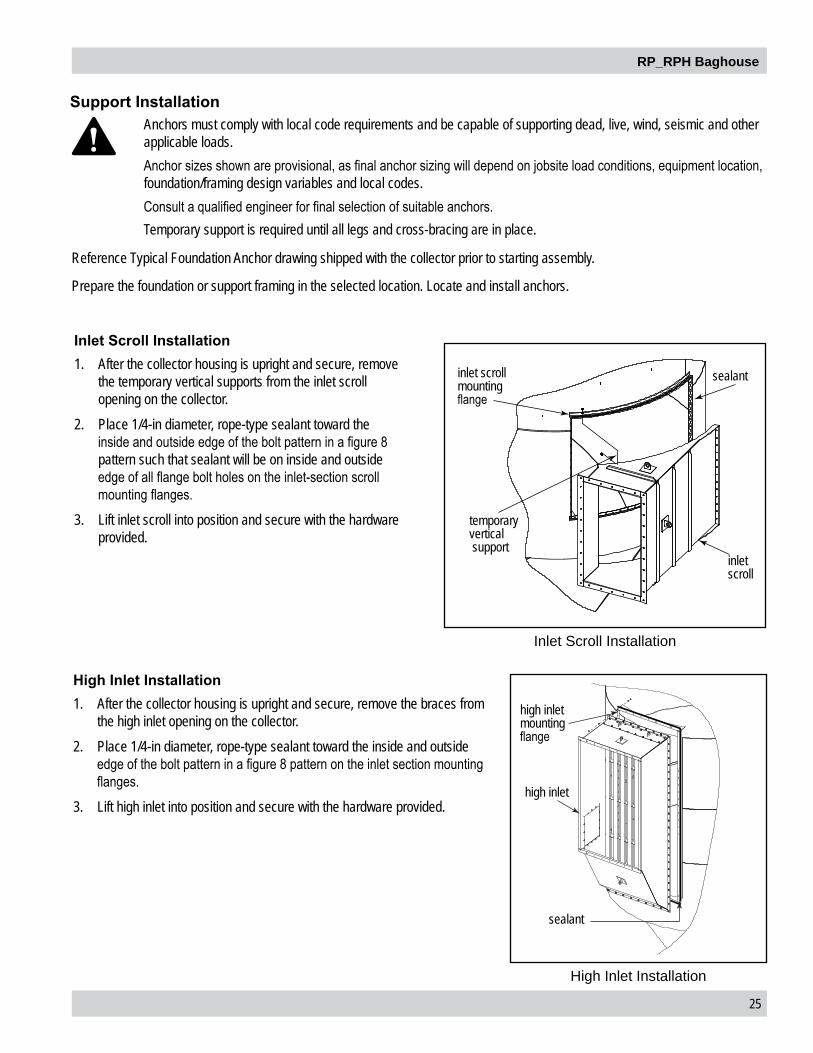
Support Installation
Reference Typical Foundation Anchor drawing shipped with the collector prior to starting assembly.
Prepare the foundation or support framing in the selected location. Locate and install anchors.
Anchors must comply with local code requirements and be capable of supporting dead, live, wind, seismic and other applicable loads.Anchor sizes shown are provisional, as final anchor sizing will depend on jobsite load conditions, equipment location, foundation/framing design variables and local codes.Consult a qualified engineer for final selection of suitable anchors.Temporary support is required until all legs and cross-bracing are in place.
High Inlet Installation1. After the collector housing is upright and secure, remove the braces from
the high inlet opening on the collector.2. Place 1/4-in diameter, rope-type sealant toward the inside and outside
edge of the bolt pattern in a figure 8 pattern on the inlet section mounting flanges.
3. Lift high inlet into position and secure with the hardware provided.
Inlet Scroll Installation1. After the collector housing is upright and secure, remove
the temporary vertical supports from the inlet scroll opening on the collector.
2. Place 1/4-in diameter, rope-type sealant toward the inside and outside edge of the bolt pattern in a figure 8 pattern such that sealant will be on inside and outside edge of all flange bolt holes on the inlet-section scroll mounting flanges.
3. Lift inlet scroll into position and secure with the hardware provided.
High Inlet Installation
high inlet mounting flange
high inlet
sealant
inlet scroll mounting flange
temporary vertical support
sealant
inlet scroll
Inlet Scroll Installation

26
Donaldson Company, Inc.
Platform and Ladder InstallationTo avoid possible severe injury or equipment damage do NOT use hand rails or ladders as a lifting point.Locate ladders to minimize risk of injury from site specific hazards including explosion relief panels.
Install the railing and ladder only after the filter housing and hopper assemblies are securely fastened to avoid damaging the platform or ladder.
Platform1. Depending on the collector model and size, the ladder/platform pack may include one or more platforms.2. For a list and schematic of components, refer to the ladder and platform (if applicable) assembly drawings provided with the
collector.3. Assemble the platform pack to the collector first.4. Continue assembling the additional ladder and platform components from top to bottom paying close attention to the
assembly drawings.5. Make sure that all platform and ladder support brackets are installed and the bottom ladder is secured to the foundation with
the appropriate brackets and anchors.
Ladder1. Assemble the ladder on the ground following the assembly
drawing provided with the ladder. Tighten all hardware securely.
2. Attach the crane’s lifting slings to the top four ladder rungs.
3. Lift the assembled ladder into position, align holes and secure ladder to the collector using the hardware provided.
4. Position lateral ladder support bracket(s) following the assembly drawing provided with the ladder.
5. Secure bottom of ladder to the ground using anchor bolts.6. Tighten all hardware.7. Remove crane.8. Ladder safety system/personal fall arrest system to be
provided by process owner or by others where required.
Ladder Installation
ladder
platform
ladder support brace
railing

RP_RPH Baghouse
27
If the collector was supplied with an electrical control panel, the wiring diagram supplied with the control panel takes precedence over the general diagrams shown in this manual.
1. The gear reducer ships prefilled with lubricant. Remove the pipe plug and install the breather.2. Remove the plastic exhaust-port plug from the bottom of the solenoid valve.3. Wire the motor to a customer-supplied motor starter with overload and short circuit protection. 4. Remove all shipping restraints from manifold arms and shipping braces from the cleaning system and cleaning system
support frame.
Cleaning Mechanism Assembly and Adjustment
Electrical installation, service, or maintenance work must be performed by a qualified electrician and comply with all applicable national and local codes.Turn power off and lock out all power before performing service or maintenance work.Do not install in classified hazardous atmospheres without an enclosure rated for the application.

28
Donaldson Company, Inc.
Cleaning Mechanism
RP diaphragm valveassembly detail
solenoid valve
secondary diaphragm cap
primary diaphragm cap
secondary diaphragm spring
primary diaphragmspring
secondary diaphragm (metal washer facing up)
primary diaphragm
solenoid valve
air tank
manifold arm
see diaphragm valve assembly detail
see diaphragm valve assembly detail
air tank
support frame
flanged worm gear reducer
RP diaphragm valve assembly detail

RP_RPH Baghouse
29
PD Pump
A positive-displacement (PD) blower provides the air used for filter cleaning and is sized for each model‘s cleaning air requirements. The PD blower should be installed on a level surface. Follow the installation instructions provided with the positive-displacement blower.
Gauge Detail
intake filter/silencer
positive-displacement blower
discharge silencer
motor
sheave
v-belt
Positive-Displacement Blower Assembly
Air Supply Pipe SizingModel Pipe Diameter
70-156 1 1/2-in200-272 2-in

30
Donaldson Company, Inc.
Perfect Pulse Controller Installation (PLC)
The PLC is used to control the filter cleaning system.
The PLC requires a 105 to 135-Volt, customer-supplied power supply.
Do not mount the PLC directly to the collector or the positive displacement blower as mechanical vibration can damage the timer.
1. Choose a location convenient for accessibility and maintenance.2. Using the wiring diagram supplied, wire the blower motor, blower-motor starter, PLC, and solenoid valve. Use appropriate wire
gauge for rated amp load as specified by the local codes.
Electrical installation, service or maintenance work during installation must be performed by a qualified electrician and comply with all applicable national and local codes.Turn power off and lock out all power before performing installation, service, or maintenance work.Do not install in classified hazardous atmospheres without an enclosure rated for the application.
Timer and Solenoid SpecificationsPower to the Perfect Pulse Controller is supplied to Terminals L1 and L2, which are intended to operate in parallel with the positive displacement blower starter’s low-voltage coil. On fan start-up, power is supplied to the timer and the preset OFF time is initiated. At the end of the OFF time, the timer energizes the solenoid valve to provide the ON time cleaning pulse for the diaphragm valve and repeats this cycle until the system is shut down. The timer can also be wired for on demand cleaning with an external pressure switch. If this option is selected, the high and low limit pressure switch relays will be connected to the TB2 corresponding terminals. Otherwise, the common and high limit terminals on TB2 are jumpered to provide continuous operation.
Note: If the collector was supplied with an electrical control panel, the wiring diagram supplied with the control panel takes precedence over the general diagrams shown in this manual.
Solenoid ConnectionThe collector is equipped with a solenoid valve (typically 120V) that controls the pulse-cleaning valve, which cleans the filters.
Electrical installation, service, or maintenance work must be performed by a qualified electrician and comply with all applicable national and local codes.This equipment may start or stop unexpectedly from a remote location. Turn power off and lock out all power before performing service or maintenance work.The appropriate wiring schematic and electrical rating must be used. See collector’s rating plate for required voltage.Do not install in classified hazardous atmospheres without an enclosure rated for the application.
Electrical Wiring

RP_RPH Baghouse
31
Input 102-132V/50-60Hz/1PhPulse ON Time Factory set at 100-milliseconds, or 1/10-second (not field adjustable)
Do not adjust pulse ON time unless the proper test equipment is available. Too much or too little ON time can cause shortened filter life.
Pulse OFF Time Factory set, the OFF time is dictated by the arm rotation speed and collector model. Refer to the table below when setting pulse only controller (PLC only).
Open the valve to the air reservoir gauge only when verifying pulse pressure and ensure the system is in the normal pulse operation if using a pulse only controller.
Model Setting66RPH, 72RP, 88RPH, 90RP 24 Spokes
132RPH, 136RP, 150RPH, 156RP, 188RPH, 200RP
48 Spokes
258RPH, 272RP 96 Spokes
Operating Temperature Range -20° F to 180° F
Solenoid Valves 120V/60 Hz intermittent duty @ 20.9 wattsInterlocking To ensure proper operation of the system the main blower should not start unless the cleaning mechanism, positive-displacement blower, and dust removal system are all operating. It is recommeded that an interlock device is installed between these motors. Failure of interlocked devices should generally not shut down the main blower, but should activate an alarm system, if available. Failure of either a rotary airlock or screw conveyor with separate drives should shut down all other drives and alarm the operator. This will avoid filling the collector with dust.
filter centerlines fall on radial lines called spokes

32
Donaldson Company, Inc.
Typical Wiring Diagram
Motor Starters
PD BLOWER
FAN
ARM DRIVE
PULSE LOGICPLC
clean down relay.
off delay. 5-10 min.
*
SOLENOID VALVE
ROTARY VALVE
PD BLOWER
ARM DRIVE
FAN
ROTARY AIRLOCK
Disconnect1FU
2FU
3FU
230 46060/3
T1T2
T3
T1T2
T3T1T2
T3
T1T2
T3
230V
120V
H1 H2H3 H4
X1
1 2
X2
STOP
FUSE
START 1CRM
1CRM
1TR-1
3P OL
3P OL
3P OL
3P OL1CRM
MS1
MS3
MS1
MS4
MS2
G
G
(OffDelay)
1TRM
L1 MS1
MS1
O.L.
O.L.
O.L.
O.L.MS4
MS4
MS3
MS3
MS2
MS2
L2
L3
*1 TR-1 allows cleaning system to operate 5-10 minutesafter fan stops
L1 L2
1
2
3
4
5
6
7
8
9
10
11
12
ARM SWITCH
The Typical Wiring Diagram is an example of a typical control panel setup. Collectors ordered with a control panel will have a specific drawing to follow that ships with the control panel.

RP_RPH Baghouse
33
Filter InstallationUse proper safety and protective equipment when removing contaminants and filters.Dirty filters may be heavier than they appear.Use care when removing filters to avoid personal injury and/or property damage.Turn power off and lock out all power before performing service or maintenance work.Do not operate with missing or damaged filters.
To access filters under the cleaning manifold arm, it is necessary to remove the chain on manifold drive sprocket to rotate pulse arms for filter removal.
1. Slowly lower the filter through the tubesheet hole.
2. Gently seat the filter flange against the tubesheet.

34
Donaldson Company, Inc.
3. Tip one side of the insert into the filter opening.
4. Push down on the other side of the insert to seat it against the filter lfange.
5. Once all parts are seated, the filter is installed properly.

RP_RPH Baghouse
35
6. If the insert is not properly seated (see below), press down on the dislodged portion. The insert may need to be taken out and put back in.
X X7. If the filter is not seated completely against the tubesheet (see below), the insert will need to be taken out and the filter
pressed down. Once the filter is properly seated, the insert can be reinstalled.
XXü

36
Donaldson Company, Inc.
Pulse Alignment
Field Adjustment Instructions1. To adjust the pulse alignment only the arm drive motor needs to be operational. All other motors and devices should be off. 2. Manually turn on the arm drive via the motor control screen. If using the pulse only PLC, turn on the arm drive motor via
customer supplied control. 3. Allow the arm to rotate and the pulse controller to start automatically. The pulse only control will start with a default pulse and
after 2 rotations it will transition to the aligned pulse mode. 4. Observe the arm from the platform through the access door as it rotates. 5. As the arm passes over the filter you will hear the solenoid “click.”6. When the arm nears the opening of the access door look down at the arm and note where the solenoid “click” occurs
regarding the center of the nozzle and the filter opening. 7. If the solenoid “click” occurs while the nozzle is within the opening of the filter insert no adjustment is needed.8. If the solenoid “click” occurs and the nozzle is partially or completely outside of the filter opening adjust as follows:
a. Turn off the arm drive motor. b. Disable all motors and devices per site
instructions. c. Note the starting position of the magnet. d. If the solenoid “click” occurs before the
centerline of the filter opening, move the magnet in the CCW direction on the bracket approximately the angular distance noted earlier.
e. If the solenoid “click” occurs after the centerline of the filter opening, move the magnet in the CW direction on the bracket approximately the angular distance noted earlier.
f. Note the new position of the magnet and properly tighten it to the bracket.
g. Leave the CAP and turn the arm drive motor back on.
h. Allow the pulse controller to start pulsing again and observe the altered alignment.
i. Repeat as needed. 9. Once the pulse is aligned no further changes should be needed.
Pulse components and associated hardware are plant installed. Due to extreme vibrations that may have been encountered during transport, instructions are included to field adjust, if necessary, the pulse components to ensure the filters are always pulsed down the centerline of the filters.
To shift the pulse location CCW, move the magnet in the CW direction on the bracket
pulse location
filter centerline

RP_RPH Baghouse
37
Optional Equipment
Plant Air KitIn place of the positive displacement cleaning blower, plant air can be used for the filter cleaning system. The plant air must be clean, dry, and filtered to prevent any oil or water from entering the cleaning system. An optional plant air kit is available to control the flow and regulate the pressure of the customer’s plant air. In addition, optional coalescing and particulate filters can be provided with this kit.
Reference the plant air manifold kit drawing shipped with the collector for installation instructions.
Optional Plant Air Kit
compressed air dump valve
filter regulator
globe valve
gauge
safety relief valve
connect to collector air reservoir tank
For reference only: coalescing and particulate filters provided by others. Compressed air supply must be clean and dry for the filter cleaning system to work properly.
*For reference only: all pipe sections, nipples, tees, adapters and unions are provided by others
connect to plant air supply*
ball valve

38
Donaldson Company, Inc.
Magnehelic® Gauge The Magnehelic is a differential pressure gauge used to measure the pressure difference between the clean-air and dirty-air plenums and provides a visual display of filter change requirements. The high-pressure tap is located in the dirty-air plenum and the low-pressure tap is located in the clean-air plenum.
1. Choose a convenient, accessible location on or near the collector for mounting that provides the best visual advantage.2. Plug the pressure ports on the back of the gauge using two, 1/8-in NPT pipe plugs supplied. Install two, 1/8-in NPT male
adapters supplied with the gauge into the high- and low-pressure ports on the side of the gauges.3. Attach the mounting bracket using three, #6-32 x 1/4-in screws supplied.4. Mount the gauge and bracket assembly to the supporting structure using two, self-drilling screws.5. Thirty-five feet of plastic tubing is supplied and must be cut in two sections. Connect one section of tubing from the gauge’s
high-pressure port to the pressure fitting located in the dirty-air plenum. Connect remaining tubing from the gauge’s low-pressure port to the fitting in the clean-air plenum. Additional tubing can be ordered from your representative.
6. Zero and maintain the gauge as directed in the manufacturer’s Operating and Maintenance Instructions provided.
Magnehelic Gauge Installation
clean-air plenum pressure tap location
flat washer
coupling
support structuremounting surface
mounting screws
mounting bracket
static pressure tee
90° elbow
adapter
adapterflat washer
dirty-air plenum pressure tap location
adapter 90° male elbow
two, self-drilling screws
two, pipe plugs
plastic tubing
two adapters
low-pressure porthigh-pressure port
Magnehelic gauge
90° male elbow

RP_RPH Baghouse
39
hopper flange
transition
hex nutflat washer
flat washer
bolt
rotary airlock
bolt
flat washer
1/4-in diameter rope type sealant placed inside bolt pattern
1/4-in diameter rope type sealant placed inside bolt pattern
flat washer
hex nut
Rotary Valve and Transition
Rotating blades can cause serious injury.Turn power off and lock out all power before performing service or maintenance work.Keep hands, feet and loose clothing away from both inlet and outlet openings to avoid injury or damage when valve is operating.
Optional discharge devices may require independent support. Discharge devices over 800 lbs. must be independently supported.Hopper discharge devices must be sized to handle anticipated dust volumes. Dust may discharge infrequently as cleaning dislodges accumulated dust at above average levels and the valves should be sized to accommodate these conditions.
Rotary Valves are used to maintain a seal on the hopper outlet while material is discharged from the hopper. A transition allows a valve to be connected to the hopper discharge when there is a size difference between the hopper outlet and the valve inlet.
Rotary Valve and Transition

40
Donaldson Company, Inc.
Flood Valve Installation1. Remove the hopper access cover and set aside.2. Align holes in flood valve access cover with holes in hopper. Secure using the flat washers and hex nuts removed in Step 1. 3. Tighten all hardware securely.
Flood Valve Installation
Sprinkler CouplingSprinkler couplings are provided for the convenience of fire control system installers. The fire control system installer shall make their own decisions on the appropriate location of fire control system components.
Explosion VentPersonal injury, death, and/or property damage can result from material discharge during venting.The material discharged during the venting of an explosion must be safely directed outdoors away from areas occupied by personnel to reduce risk of personal injury and/or property damage. The risk of personal injury and/or property damage can be minimized or avoided by locating vented equipment outside buildings and away from normally occupied areas.Explosion vents should be inspected regularly to confirm physical and operational condition. Replace any damaged parts immediately.Standard explosion vents are intended for outdoor installations only.Unless otherwise noted, the explosion venting calculations are based on formulas from NFPA-68 for outdoor applications only, with no duct or obstructions on the explosion vent panel.
Contact Donaldson Torit for assistance in calculating specific venting requirements for equipment.
NFPA 68 can provide guidance on both the frequency of and appropriate details for inspections.

RP_RPH Baghouse
41
Start-up / Commissioning
1. Check all electrical connections for tightness and contact.2. Check for proper rotation on all motors as described below.
Do not look into fan outlet to determine rotation. View the fan rotation through the back of the motor.Check that the exhaust plenum is free of tools or debris before checking fan rotation.Stand clear of exhaust to avoid personal injury.Do not interchange a power lead with the ground wire. Severe personal injury and/or property damage may result.
a. Bump” the fan to initiate rotation.b. As the fan is winding down (unpowered) compare fan rotation to the rotation label (located on fan housing) direction.
3. If the fan rotation is reversed, correct the rotation.
a. Lock-Out all energy sources.b. Within the junction box, swap the connection location of two power leads on the terminal block, making certain not to
swap a power lead and the ground wire. To reverse rotation, single-phase power supply: Follow manufacturer’s instructions on the motor’s nameplate. To reverse
rotation, three-phase power supply: Switch any two leads on the motor junction box. Do not interchange a power lead with a ground wire or severe personal injury and/or property damage may result.
4. Ensure all equipment access panels are sealed and secure.5. Check that the hopper discharge system is properly sealed as needed to keep the collector under operating pressure.6. Check that fan exhaust damper (if applicable) is set to the fully-closed position.7. Check and remove all loose items in or near the inlet and outlet of the collector.8. Check that all remote controls and system components are properly wired and all service switches are in the OFF position.9. Check that all optional accessories are installed properly and secured.10. Ensure all filters are installed and properly seated in the tubesheet.11. Turn power ON at source.12. Turn powered hopper discharge devices ON.13. Turn pulse system ON.14. Turn fan motor ON.15. Adjust airflow with the Airflow Controller or exhaust damper.
Excess airflow can shorten filter life, cause electrical system failure and fan motor failure.
16. Ensure fire mitigation system water is installed and functioning correctly, if present.
Instruct all personnel on safe use and maintenance procedures.
Electrical installation, service, or maintenance work must be performed by a qualified electrician and comply with all applicable national and local codes. This equipment may start or stop unexpectedly from a remote location. Turn power off and lock out all power before performing service or maintenance work.Turn compressed air supply OFF, bleed and lock out lines before performing service or maintenance work.Check that the collector is clear and free of all debris before starting.Do not install in classified hazardous atmospheres without an enclosure rated for the application.

42
Donaldson Company, Inc.
Once the collector has reached the end of operational life it will need to be decommissioned.
During decommissioning, there is potential for exposure to the dust in the collector. Most dusts present safety and health hazards that require precautions. Wear eye, respiratory, head, and other protection equipment suitable for the type of dust when performing any decommissioning activities.LOCK-OUT all energy sources prior to performing any decommissioning activities on the equipment.Electrical service must be performed by a qualified electrician.Disconnection of ducts must be performed by a qualified tinsmith or contractor.
1. Follow the typical shut-down sequence steps located in the operation section to remove as much contaminant from collector as possible.
2. Lock-Out all energy sources.3. Remove all filters from the collector and dispose of in a suitable fashion for the dust in the collector. (See Filter Replacement
for removal instructions).4. Disconnect electrical power from the collector and remove any associated conduit or hardware from the exterior of the
collector.5. Clear residual dust accumulations from surfaces inside the collector and associated components in a fashion suitable for the
dust, prior to further disassembly.6. Disconnect all ducts from the collector.7. Proceed to disassemble collector by removing sub-assemblies in the reverse order of the steps given in Appendix A. Note: The clean air plenum, dirty air plenum, tube sheet, H-frame and cleaning assembly may be removed in separate steps
instead of as one unit.8. Secure all collector components to a suitable transport carrier and transport to a disposal site suitable for the dust in the
collector.
Decommissioning

RP_RPH Baghouse
43
Model Number _________________________________ Serial Number ___________________________________
Ship Date _____________________________________ Installation Date __________________________________
Filter Type_____________________________________________________________________________________
Collected Dust _________________________________________________________________________________
Dust Properties: Kst _______________Pmax ______________ MIE ____________ MEC __________________
Accessories ___________________________________________________________________________________
Other ________________________________________________________________________________________
_____________________________________________________________________________________________
Product Information (Process Owner to complete and retain for your records)

44
Donaldson Company, Inc.
Service NotesDate Service Performed Notes

RP_RPH Baghouse
45
Date Service Performed Notes

46
Donaldson Company, Inc.
Service NotesDate Service Performed Notes

RP_RPH Baghouse
47
Donaldson warrants to the original purchaser only that the Goods will be free from defects in material and manufacture for the applicable time periods stated below: (1) Major structural components for a period of ten (10) years from the date of shipment; (2) Non-Structural, Donaldson-built components and accessories including Donaldson Airlocks, TBI Fans, TRB Fans, Fume Collector products, Donaldson built electrical control components, and Donaldson-built Afterfilter housings for a period of twelve (12) months from date of shipment; and (3) Donaldson-built filter elements for a period of eighteen (18) months from date of shipment.
Buyer is solely responsible for determining if goods fit Buyer’s particular purpose and are suitable for Buyer’s process and application. Seller’s statements, engineering and technical information, and recommendations are provided for the Buyer’s convenience and the accuracy or completeness thereof is not warranted. If, after Seller receives written notice, within the warranty period, that any goods allegedly do not meet Seller’s warranty, and Seller, in its sole discretion, determines that such claim is valid, Seller’s sole obligation and Buyer’s exclusive remedy for breach of the foregoing warranty or any Seller published warranty, will be, at Seller’s option, either: (i) repair or replacement of such goods or (ii) credit or refund to Buyer for the purchase price from Seller. In the case of repair or replacement, Seller will be responsible for the cost of shipping the parts but not for labor to remove, repair, replace or reinstall the allegedly defective goods. Refurbished goods may be used to repair or replace the goods and the warranty on such repaired or replaced goods shall be the balance of the warranty remaining on the goods which were repaired or replaced. Any repair or rework made by anyone other than Seller is not permitted without prior written authorization by Seller, and voids the warranty set forth herein. Seller warrants to Buyer that it will perform services in accordance with the Sales Documents using personnel of required skill, experience and qualifications and in a professional and workmanlike manner in accordance with generally recognized industry standards for similar services. With respect to any services subject to a claim under the warranty set forth above, Seller shall, in its sole discretion, (i) repair or re-perform the applicable services or (ii) credit or refund the price of such services at the pro rata contract rate and such shall be Seller’s sole obligation and the exclusive remedy for breach of the foregoing warranty on services. Products manufactured by a third party (“Third Party Product”) may constitute, contain, be contained in, incorporated into, attached to or packaged together with, the goods. Buyer agrees that: (a) Third Party Products are excluded from Seller’s warranty in this Section 7 and carry only the warranty extended by the original manufacturer, and (b) Seller’s liability in all cases is limited to goods of Seller’s design and manufacture only. EXCEPT FOR SELLER’S WARRANTY OF TITLE TO THE GOODS, SELLER EXPRESSLY DISCLAIMS AND EXCLUDES ALL OTHER WARRANTIES WHATSOEVER, WHETHER, EXPRESSED OR IMPLIED, ORAL, STATUTORY, OR OTHERWISE, INCLUDING BUT NOT LIMITED TO MERCHANTABILITY, FITNESS FOR A PARTICULAR PURPOSE, NON-INFRINGEMENT OF THIRD PARTY INTELLECTUAL PROPERTY AND ANY WARRANTIES ARISING FROM TECHNICAL ADVICE OR RECOMMENDATIONS, COURSE OF DEALING OR OF PERFORMANCE, CUSTOM OR USAGE OF TRADE. Seller’s obligations do not cover normal wear and tear or deterioration, defects in or damage to any goods resulting from improper installation, accident or any utilization, maintenance, repair or modification of the goods, or any use that is inconsistent with Seller’s instructions as to the storage, installation, commissioning or use of the goods or the designed capabilities of the goods or that, in its sole judgment, the performance or reliability thereof is adversely affected thereby, or which is subjected to abuse, mishandling, misuse or neglect or any damage caused by connections, interfacing or use in unforeseen or unintended environments or any other cause not the sole fault of Seller, and shall be at Buyer’s expense. Seller’s warranty is contingent upon the accuracy of all information provided by Buyer. Any changes to or inaccuracies in any information or data provided by Buyer voids this warranty. Seller does not warrant that the operation of the goods will be uninterrupted or error-free, that the functions of the goods will meet Buyer’s or its customer’s requirements unless specifically agreed to, or that the goods will operate in combination with other products selected by Buyer or Buyer’s customer for its use.
The terms of this warranty may only be modified by a special warranty document signed by a Director, General Manager or Vice President of Donaldson. To ensure proper operational performance of your equipment, use only genuine Donaldson replacement parts.
This Product is provided subject to and conditioned upon Donaldson’s Terms of Sale (“Terms”), a current copy of which is located at termsofsale.donaldson.com. These Terms are incorporated herein by reference. By purchasing or using this Product, the user accepts these Terms. The Terms are available on our website or by calling our customer service line at 1-800-365-1331.
Donaldson Industrial Air Filtration Warranty

Important Notice: Many factors beyond the control of Donaldson can affect the use and performance of Donaldson products in a particular application, including the conditions under which the product is used. Since these factors are uniquely within the user’s knowledge and control, it is essential the user evaluate the products to determine whether the product is fit for the particular purpose and suitable for the user’s application. All products, product specifications, availability and data are subject to change without notice, and may vary by region or country.
Significantly improve the performance of your collector with genuine Donaldson Torit replacement filters and parts. Call Donaldson Torit at 800-365-1331.AST Canada 905-821-8860