Embed Size (px)
Citation preview

Team members:
Cristian Arcega (Sr.), Adam Burch (Jr.), Daniel Federle (Soph.) , Annalisa
Regalado (Sr.), Lorenzo Santillan (Sr.) , Pablo Santillan (Soph.)
Faculty mentors:
Dr. Allan Cameron, Greg Harrison, Jim Haugen, Fredi Lajvardi
Industry mentors:
Jerry Little, Dr. Karen Suhm, Marcos Garcia-Acosta
Carl Hayden Community High School Falcon Robotics
Remotely Operated Vehicle Team
MATE National ROV Championships 2006
Project Janus
Prepared by Annalisa Regalado
Ipski Pipski Otis
• Abstract…………………………………………………………1
• Design Rationale…………………………………………...2
• Interesting & Unique Challenge……………………....3
• Troubleshooting Techniques…………………………..5
• Skills Gained………………………………………………….6
• Expenditures………………………………………………….7
• Software Flow Chart……………………………………….8
• Lithium Polymer Batteries………………………………9
• Fiber Optic System………………………………………..10
• Pilot Control Panel………………………………………...11
• Electrical Schematics………………………………….…12
• Future Improvements…………………………………...16
• Ocean Observing Systems……………………………...17
• Acknowledgements……………………………………….18
Prepared by Annalisa Regalado

1
The Carl Hayden ROV Team has competed in the Explorer Class of the MATE
ROV Competition for the past two years. With the experience gained from previous
competitions the team has learned much about creating a capable ROV.
The team has taken a different approach to accomplish the mission scenarios
in this year’s competition. We have completed two ROVs which will perform simul-
taneously to complete the mission tasks faster and more efficiently while staying
within mission parameters.
The first ROV, named Ipski-Pipski, will utilize an onboard battery and a fiber
optic tether which makes it a very maneuverable ROV, ideal for fine turns and pre-
cise actions. The second ROV, named Otis, was designed to fully utilize the higher
voltage and current that is allowed by using surface power. Its thrusters are more
powerful to facilitate the delivery of heavy objects to the pool floor.
These two ROVs have been designed to complement each other. By splitting
up the duties between two ROVs they will individually accomplish the tasks each is
better equipped to undertake. By using this strategy the team plans to accomplish
all the mission tasks well within the maximum time allotted.
This scientific endeavor represents another educational “doorway” in our
growth as students of science and technology, reminding us of Janus, the mytho-
logical guardian of portals. In addition, the use of dual robots reflects the dual face
of this Roman god. For these reasons, it was decided that Project Janus best
represents the nature of our approach to this year’s MATE mission.
Ipski-Pipski Otis
Prepared by Cristian Arcega

2
Based on last year’s mission ex-
perience the team decided to make a
smaller ROV. The team felt that the
ROV last year was too large for on-
board power, and we believe that on-
board power is the better approach for
these particular types of ROV func-
tions under these mission conditions.
To accomplish this year’s goal, we
built smaller cameras and selected
smaller thrusters. Basically, we minia-
turized the ROV. As we were building
the ROV, we realized that this smaller,
more compact ROV might not be able to deliver the electronics module down 12.19 me-
ters to the trawl resistant frame in a short amount of time. Furthermore, this year it ap-
pears likely that more teams will be able to finish the mission within the 30 minute time
period. We concluded that if we had two ROVs, the team would be able to do more parts
of the mission simultaneously. We believe that this idea will allow us to complete the mis-
sion under the 30 minutes to get additional bonus points. Having two ROVs also allows for
each to be specifically designed for certain tasks, making accomplishing the tasks easier.
The first ROV, Ipski Pipski, is designed to be a finesse robot. It will be assigned the
task of retrieving the instrument cable connector with its attached cable from the sea
floor and lay or weave the cable through 4 waypoints. After having laid the cable through
the waypoints, Ipski will then insert the cable connector into the electronics module. To
have this maneuverability, this ROV will be small and compact and have 5 thrusters to go
in any direction. It will also have on board lithium polymer batteries and will be equipped
with a fiber optic tether to the surface for control. The ROV will also have a grabber ma-
nipulator to handle objects. One drive camera and 4 auxiliary cameras will be used to
show views from various vantage points of the ROV.
The second ROV, Otis, will focus on delivering the electronics module to the trawl
resistant frame in the shortest amount of time. It is bigger and more powerful than Ipski
because it uses surface voltage of 36 volts for its vertical thrusters. It also has 12 volt
thrusters for horizontal direction to allow for finer movements than the 36 volt thrusters
are capable of. Its secondary task is to open the trawl resistant frame door that will re-
veal the ports into which the power and communication connectors must be inserted. The
larger 12 volt thrusters on Otis will ensure that opening the door is no problem. Otis will
also have a grabber manipulator for opening the door and grasping other objects. The
third task is for Otis to retrieve the power connector and insert it into the power port.
Each ROV will require three operators—two pilots and one tether management per-
sonnel. The team feels that for this particular mission this design rationale will ensure the
best possible chance for success.
Prepared by Lorenzo Santillan
3
One challenge that our team overcame was designing an innovative, inex-
pensive, and reliable housing for our ROV’s controls and connections. In previ-
ous years we have used a “watertight” case to house all of our electronics.
These cases are not 100% reliable to stay sealed. Team members who need to
check for a leak had to open the case to verify if there was a problem. Having
to break the o-ring seal each time to check our housing contributes to lower reli-
ability and critical time spent opening and closing the case. To overcome this
drawback, our team designed a housing made out of a metal serving pan from a
restaurant buffet line covered by a transparent sheet of 1.27cm (1/2”) thick
Lexan (Plexiglas).
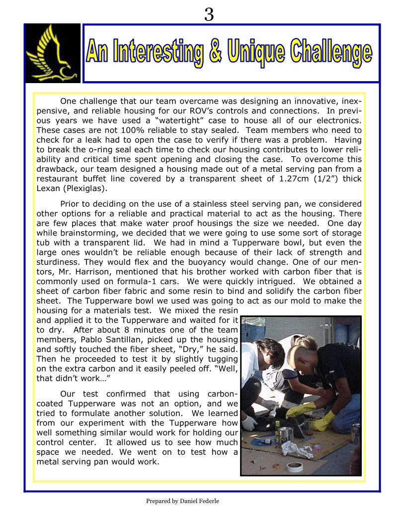
Prior to deciding on the use of a stainless steel serving pan, we considered
other options for a reliable and practical material to act as the housing. There
are few places that make water proof housings the size we needed. One day
while brainstorming, we decided that we were going to use some sort of storage
tub with a transparent lid. We had in mind a Tupperware bowl, but even the
large ones wouldn’t be reliable enough because of their lack of strength and
sturdiness. They would flex and the buoyancy would change. One of our men-
tors, Mr. Harrison, mentioned that his brother worked with carbon fiber that is
commonly used on formula-1 cars. We were quickly intrigued. We obtained a
sheet of carbon fiber fabric and some resin to bind and solidify the carbon fiber
sheet. The Tupperware bowl we used was going to act as our mold to make the
housing for a materials test. We mixed the resin
and applied it to the Tupperware and waited for it
to dry. After about 8 minutes one of the team
members, Pablo Santillan, picked up the housing
and softly touched the fiber sheet, “Dry,” he said.
Then he proceeded to test it by slightly tugging
on the extra carbon and it easily peeled off. “Well,
that didn’t work…”
Our test confirmed that using carbon-
coated Tupperware was not an option, and we
tried to formulate another solution. We learned
from our experiment with the Tupperware how
well something similar would work for holding our
control center. It allowed us to see how much
space we needed. We went on to test how a
metal serving pan would work.
Prepared by Daniel Federle
4
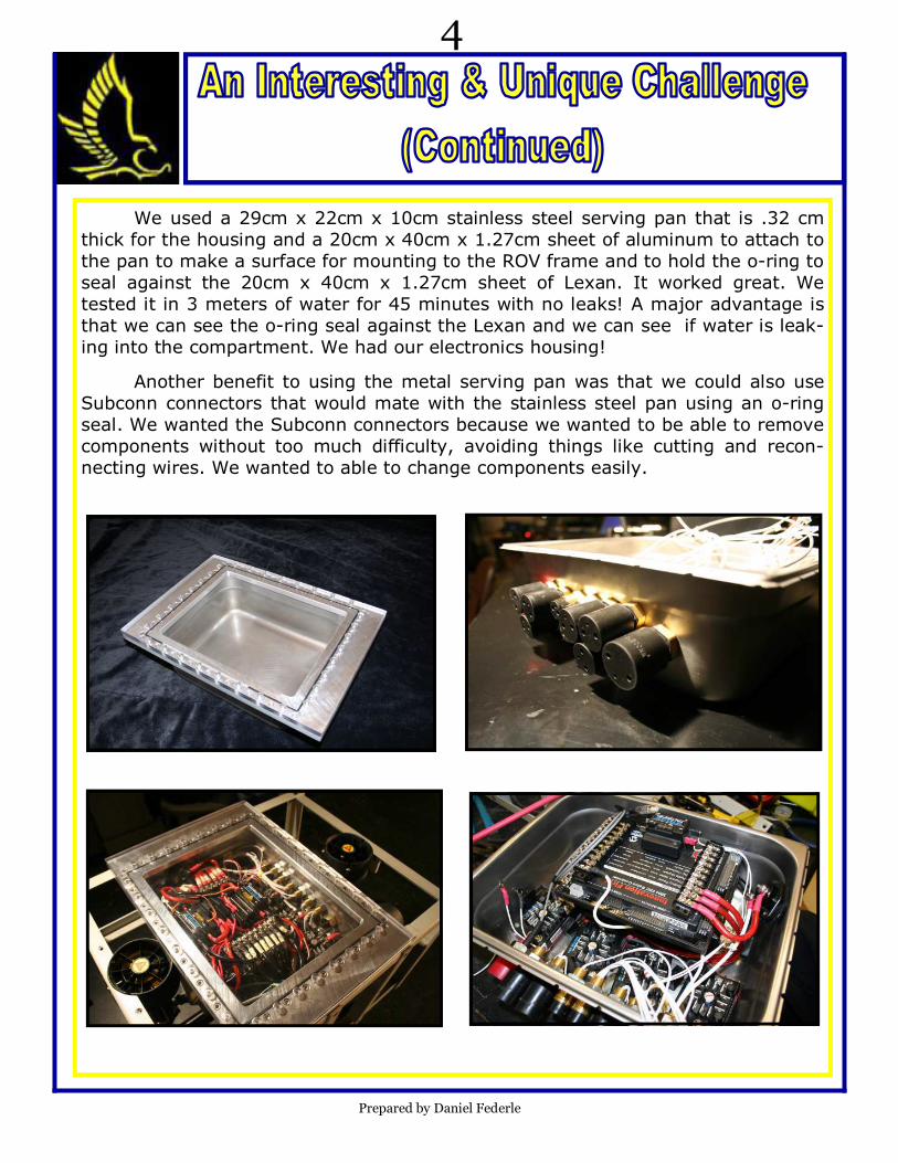
We used a 29cm x 22cm x 10cm stainless steel serving pan that is .32 cm
thick for the housing and a 20cm x 40cm x 1.27cm sheet of aluminum to attach to
the pan to make a surface for mounting to the ROV frame and to hold the o-ring to
seal against the 20cm x 40cm x 1.27cm sheet of Lexan. It worked great. We
tested it in 3 meters of water for 45 minutes with no leaks! A major advantage is
that we can see the o-ring seal against the Lexan and we can see if water is leak-
ing into the compartment. We had our electronics housing!
Another benefit to using the metal serving pan was that we could also use
Subconn connectors that would mate with the stainless steel pan using an o-ring
seal. We wanted the Subconn connectors because we wanted to be able to remove
components without too much difficulty, avoiding things like cutting and recon-
necting wires. We wanted to able to change components easily.
Prepared by Daniel Federle
5
In the team’s history we have always gone the extra step to make sure
that all of our equipment is low maintenance, cost effective, easy to operate
and easy to repair when needed. The first step is to limit the possibility of a
problem occurring. We accomplish this by having as many spare parts as pos-
sible, avoiding the use of unique or very expensive parts that are hard to re-
place, and keeping the workshop clean and organized. The basic approach of
our troubleshooting technique is to always start investigating the issue from
the macro point of view and then move to the micro point of view. This is an
ethic that all of our team members learn from years of building experience. In
solving problems we always follow a general algorithm, analyzing the problem
and taking the logical steps towards the goal of getting the system back
online.
One strategy in attacking problems involves using laptops with a
dashboard viewing program that is connected to the Dashboard Viewer port of
the operator interface, to view all of the ROV's data. From this laptop the pilot
can diagnose many of the problems associated with the ROV. Here the pilots
can also see real-time information on the ROV's motors and cameras. Having
the ability to see the real-time information about the ROV is crucial in the
event that an issue surfaces. From this point the pilots asses their options and
they proceed to fix many of the problems.
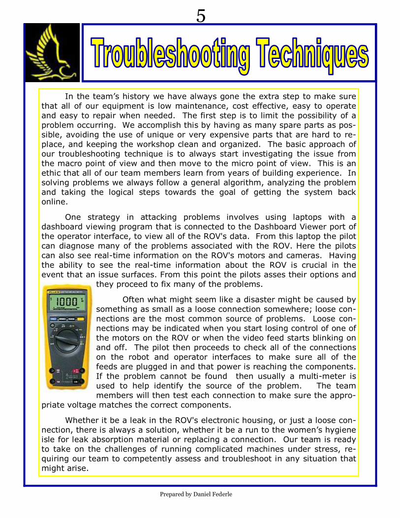
Often what might seem like a disaster might be caused by
something as small as a loose connection somewhere; loose con-
nections are the most common source of problems. Loose con-
nections may be indicated when you start losing control of one of
the motors on the ROV or when the video feed starts blinking on
and off. The pilot then proceeds to check all of the connections
on the robot and operator interfaces to make sure all of the
feeds are plugged in and that power is reaching the components.
If the problem cannot be found then usually a multi-meter is
used to help identify the source of the problem. The team
members will then test each connection to make sure the appro-
priate voltage matches the correct components.
Whether it be a leak in the ROV's electronic housing, or just a loose con-
nection, there is always a solution, whether it be a run to the women’s hygiene
isle for leak absorption material or replacing a connection. Our team is ready
to take on the challenges of running complicated machines under stress, re-
quiring our team to competently assess and troubleshoot in any situation that
might arise.
Prepared by Daniel Federle

6
During this season’s build period for our
ROV, we learned a skill that is invaluable to our
ROV’s dependability and simplicity. We learned
how to utilize the chemical rubber bonding agent
3m Scotchcast 2130. Using this compound we
are now able to join any two cables in a com-
pletely water-proof medium.
The complete process takes approximately
two hours. We made our own mold for the
Scotchcast out of a 1.27 cm (1/2 inch) PVC pipe.
In the mold we made a slit with a Dremel with a
grinding wheel, to have a place through which
we could inject the liquid Scotchcast. Connect-
ing two cables together is simple. First, we put
the mold over one of the cables we were work-
ing with before soldering the wires to-
gether. Second, we connected the other cable
with our solder connections staggered with re-
spect to each other to prevent shorting out if the
two wires touched. Third, we used the self-
vulcanizing tape to hold the mold in
place. Next, we took out the Scotchcast pack-
age and ruptured the membrane that separates
the rubber chemical from the hardening chemi-
cal so that they could mix. After about one min-
ute of mixing the two chemicals inside this
pouch, we cut open the corner of it and inserted
a 100ml syringe, taking up enough of the black
rubber chemical to fill it. Once the syringe was
full, we injected the compound into the PVC
mold and allowed it to dry for about an hour be-
fore cutting open the mold with the Dremel us-
ing the same grinding wheel used to make the
slits in the mold.
This method is now the first choice to any
situation in which we have to bond any two ca-
bles or wires, whether it be motor controls or
camera feed; we can connect them and know
that they will remain 100% waterproof.
Prepared by Daniel Federle
7
Prepared by Annalisa Regalado
8
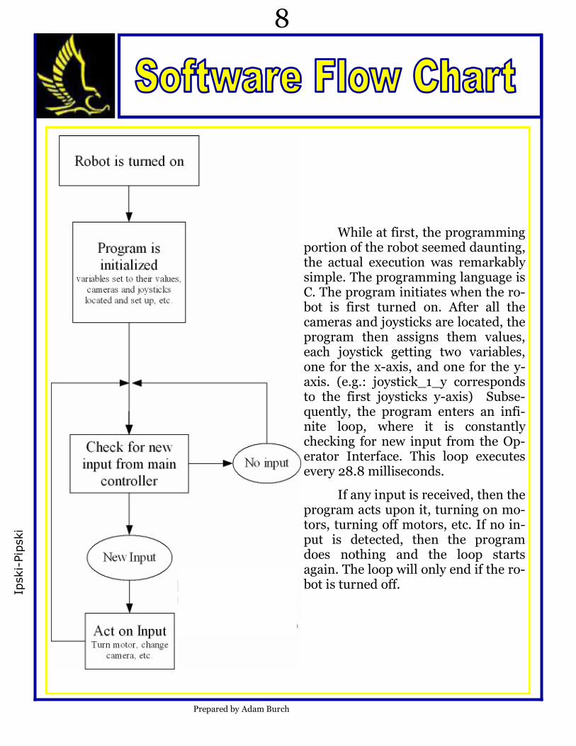
While at first, the programming portion of the robot seemed daunting, the actual execution was remarkably simple. The programming language is C. The program initiates when the ro-bot is first turned on. After all the cameras and joysticks are located, the program then assigns them values, each joystick getting two variables, one for the x-axis, and one for the y-axis. (e.g.: joystick_1_y corresponds to the first joysticks y-axis) Subse-quently, the program enters an infi-nite loop, where it is constantly checking for new input from the Op-erator Interface. This loop executes every 28.8 milliseconds.
If any input is received, then the program acts upon it, turning on mo-tors, turning off motors, etc. If no in-put is detected, then the program does nothing and the loop starts again. The loop will only end if the ro-bot is turned off.
Ipski-Pipski
Prepared by Adam Burch
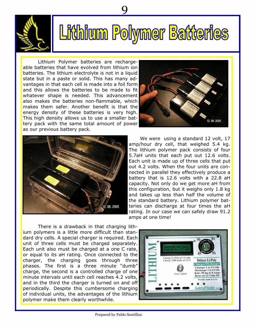
Lithium Polymer batteries are recharge-
able batteries that have evolved from lithium ion
batteries. The lithium electrolyte is not in a liquid
state but in a paste or solid. This has many ad-
vantages in that each cell is made into a foil form
and this allows the batteries to be made to fit
whatever shape is needed. This advancement
also makes the batteries non-flammable, which
makes them safer. Another benefit is that the
energy density of these batteries is very high.
This high density allows us to use a smaller bat-
tery pack with the same total amount of power
as our previous battery pack.
We were using a standard 12 volt, 17
amp/hour dry cell, that weighed 5.4 kg.
The lithium polymer pack consists of four
5.7aH units that each put out 12.6 volts.
Each unit is made up of three cells that put
out 4.2 volts. When the four units are con-
nected in parallel they effectively produce a
battery that is 12.6 volts with a 22.8 aH
capacity. Not only do we get more aH from
this configuration, but it weighs only 1.8 kg
and takes up less than half the volume of
the standard battery. Lithium polymer bat-
teries can discharge at four times the aH
rating. In our case we can safely draw 91.2
amps at one time!
There is a drawback in that charging lith-
ium polymers is a little more difficult than stan-
dard dry cells. A special charger is required. Each
unit of three cells must be charged separately.
Each unit also must be charged at a one C rate,
or equal to its aH rating. Once connected to the
charger, the charging goes through three
phases. The first is a three minute “dumb”
charge, the second is a controlled charge of one
minute intervals until each cell reaches 4.2 volts,
and in the third the charger is turned on and off
periodically. Despite this cumbersome charging
of individual units, the advantages of the lithium
polymer make them clearly worthwhile.
Prepared by Pablo Santillan
9
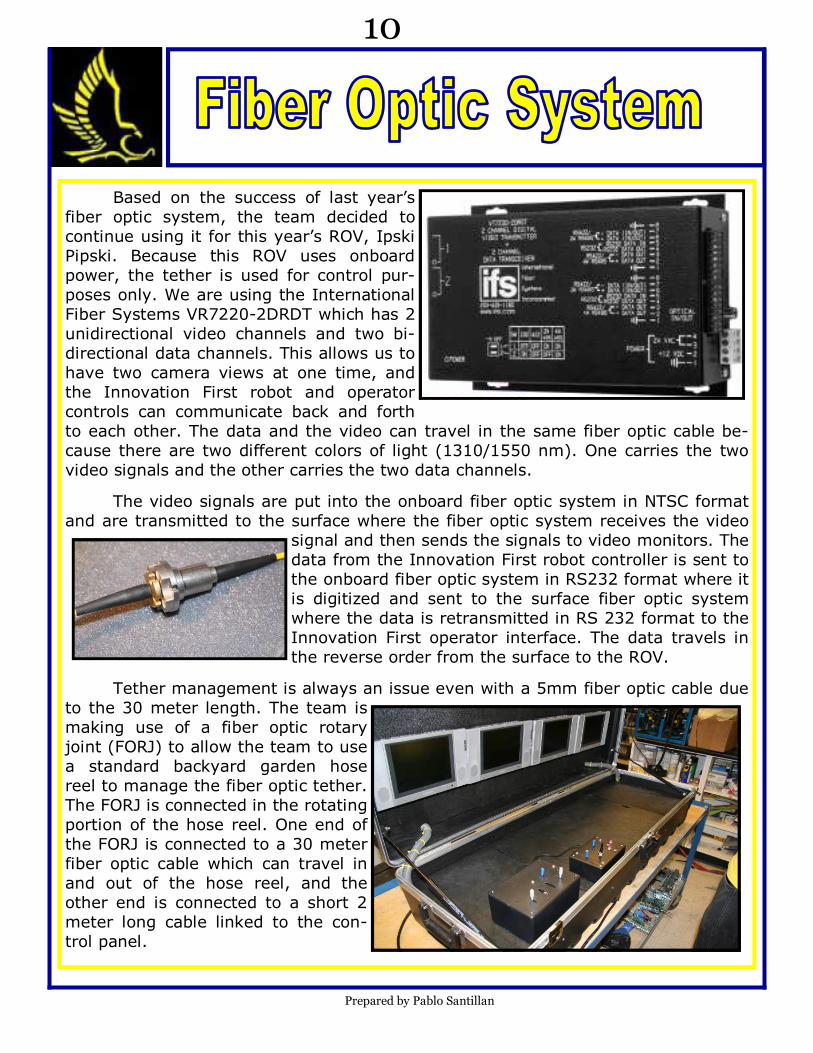
Based on the success of last year’s
fiber optic system, the team decided to
continue using it for this year’s ROV, Ipski
Pipski. Because this ROV uses onboard
power, the tether is used for control pur-
poses only. We are using the International
Fiber Systems VR7220-2DRDT which has 2
unidirectional video channels and two bi-
directional data channels. This allows us to
have two camera views at one time, and
the Innovation First robot and operator
controls can communicate back and forth
to each other. The data and the video can travel in the same fiber optic cable be-
cause there are two different colors of light (1310/1550 nm). One carries the two
video signals and the other carries the two data channels.
The video signals are put into the onboard fiber optic system in NTSC format
and are transmitted to the surface where the fiber optic system receives the video
signal and then sends the signals to video monitors. The
data from the Innovation First robot controller is sent to
the onboard fiber optic system in RS232 format where it
is digitized and sent to the surface fiber optic system
where the data is retransmitted in RS 232 format to the
Innovation First operator interface. The data travels in
the reverse order from the surface to the ROV.
Tether management is always an issue even with a 5mm fiber optic cable due
to the 30 meter length. The team is
making use of a fiber optic rotary
joint (FORJ) to allow the team to use
a standard backyard garden hose
reel to manage the fiber optic tether.
The FORJ is connected in the rotating
portion of the hose reel. One end of
the FORJ is connected to a 30 meter
fiber optic cable which can travel in
and out of the hose reel, and the
other end is connected to a short 2
meter long cable linked to the con-
trol panel.
Prepared by Pablo Santillan
10
11
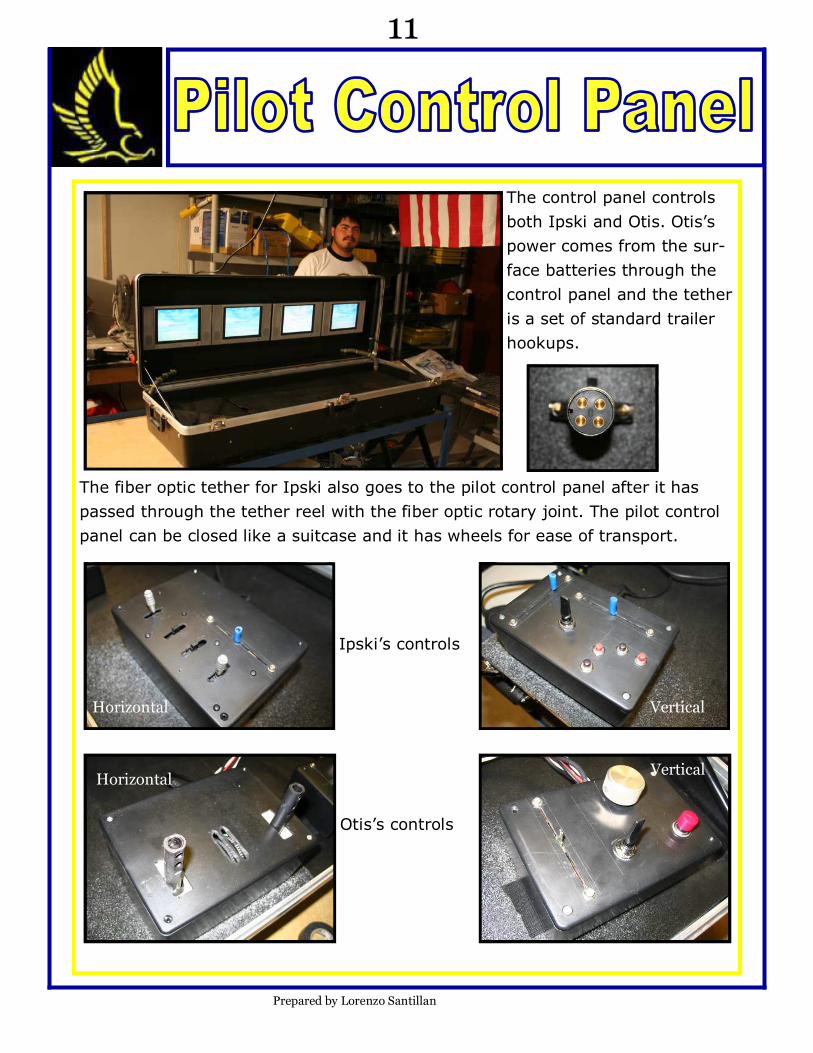
The control panel controls
both Ipski and Otis. Otis’s
power comes from the sur-
face batteries through the
control panel and the tether
is a set of standard trailer
hookups.
The fiber optic tether for Ipski also goes to the pilot control panel after it has
passed through the tether reel with the fiber optic rotary joint. The pilot control
panel can be closed like a suitcase and it has wheels for ease of transport.
Ipski’s controls
Otis’s controls
Prepared by Lorenzo Santillan
Horizontal Vertical
Horizontal Vertical
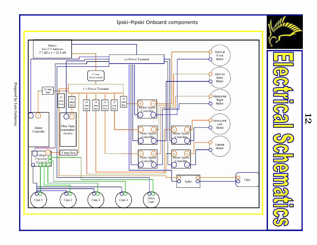
Ipski-Pipski Onboard components
Prep
ared
by Luis G
utierrez
12
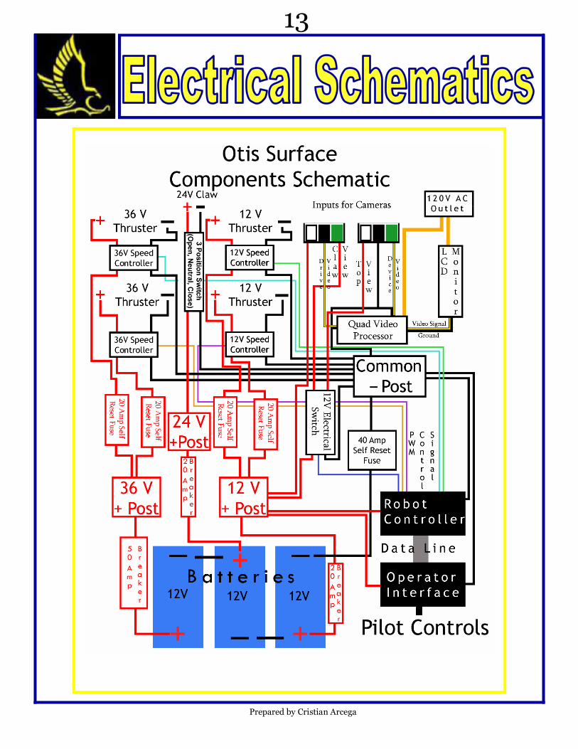
Prepared by Cristian Arcega
13

Prep
ared
by Luis G
utierrez
Pilot controls for Ipski Pipski
14

Prepared by Cristian Arcega
Left
1
6 3
Right
24v
To Grabber
To Grabber
Camera 1 / 2
Vertical
Vertical
1
2
6
4
3
Pilot controls for Otis
15
Operator interface pin outs port 3
Operator interface pin outs port 4
The Carl Hayden Falcon Robotics Team strives to use innovative improvements to
create better ROVs. A large portion of the team’s success in performing mission tasks in
previous years is due to the use of the smallest tether available. A tether has potential
drawbacks on any ROV. Improvements in data communication technology has enabled
the team to use a single fiber optic cable to relay information between the user and
ROV, however any tether is still cumbersome. As a tether, fiber optic cables have mini-
mal drag, but can get caught on objects in the environment or other ROVs nearby. In
many cases, if the tether were to become severed or damaged the ROV would be lost
without a possibility of retrieving it.
With this in mind, the team is attempting to utilize high intensity LEDs of a
cyan hue to transmit data wirelessly between two sources—the ROV and operator. A
buoy stationed above the general position of the ROV will act as a transmitter and data
receiver and video at the surface of the water while communicating with the submersed
ROV. However, in order to ensure communication between the two sources a CMU cam-
era would be mounted to the ROV. This CMU Camera can be pre-programmed to track
the desired light source, in this case the transceiver at the surface. Onboard processors
and servos would keep the ROV’s transmitter and receiver of data pointed at the cor-
rect direction to keep contact between the two systems. While this way of keeping in
contact with the surface is more delicate than a standard tethering system, it would al-
leviate the risk of entanglement of the ROV as well as remove any drag from the tether
line.
Despite its advantages, this system is in its initial stages with several
problems needing to be solved before it can be relied upon. Current technology keeps
the bandwidth of the system very limited. It is enough to transmit packet data for
movement but not enough to provide quality video feed from the ROV. Therefore, any
ROV using this method would have to be driven with a poor video feed. Another draw-
back pertains to the method of communication. Since data would be transmitted visu-
ally, the ROV must always stay within the acceptable range and position in order to
maintain visual contact with the surface. Objects that obstruct their visual contact can
disrupt communication and the ROV could be lost. Visibility in water also differs greatly
depending on the environment. Light emitted from communication would affect marine
life in the light beam’s path. Any fish that swim into the beam of light would be blinded.
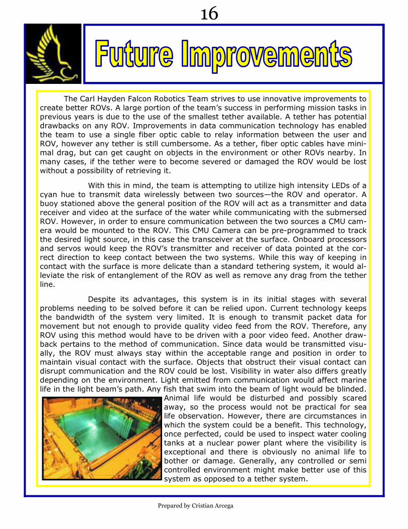
Animal life would be disturbed and possibly scared
away, so the process would not be practical for sea
life observation. However, there are circumstances in
which the system could be a benefit. This technology,
once perfected, could be used to inspect water cooling
tanks at a nuclear power plant where the visibility is
exceptional and there is obviously no animal life to
bother or damage. Generally, any controlled or semi
controlled environment might make better use of this
system as opposed to a tether system.
Prepared by Cristian Arcega
16
One of the greatest limitations to underwater exploration involves the link used to
retrieve data from the environment being studied. Transmission lines can easily get tan-
gled or damaged and can severely limit the range of motion of an exploring ROV. Im-
provements in underwater robotics technology have enabled scientists to explore
greater water depths more effectively, but ROV systems are still highly dependent on
their ties to the surface, where researchers observe what the ROVs are doing.
One group of researchers from the Research School of Information Sciences and
Engineering at the Australian National University has been working to find a more effec-
tive way to connect ROVs to their users. This project is called AMOUR, autonomous
modular optical underwater robot. This group has succeeded in establishing communica-
tion between ROVs and top-side users not by attaching tethers to their ROVs, but rather
by sending pulses of light from the ROVs to a stationary data transceiver. Their re-
search shows that the wireless communication between the ROVs and the central trans-
ceiver can work over short distances and even with multiple ROVs at one time.
In the Australian group’s design, both the central transceiver and the operating
ROVs have the ability to transmit and receive data to and from each other through the
use of high intensity LEDs. The central device, the only machine tethered to the sur-
face, remains stationary and serves as a data transmit and receive post for the ROVs.
This transceiver sends orders to the ROVs, which gather the desired data and then
transmit the data back to the central data post, which feeds it to the surface via the
tether -- in this case, a fiber optic cable which transmits data using a fiber optic multi-
plexer. The ROVs themselves can also be used as relay stations to transmit information
to other ROVs that may be out of range or out of the line of sight of the detector on the
central transceiver.
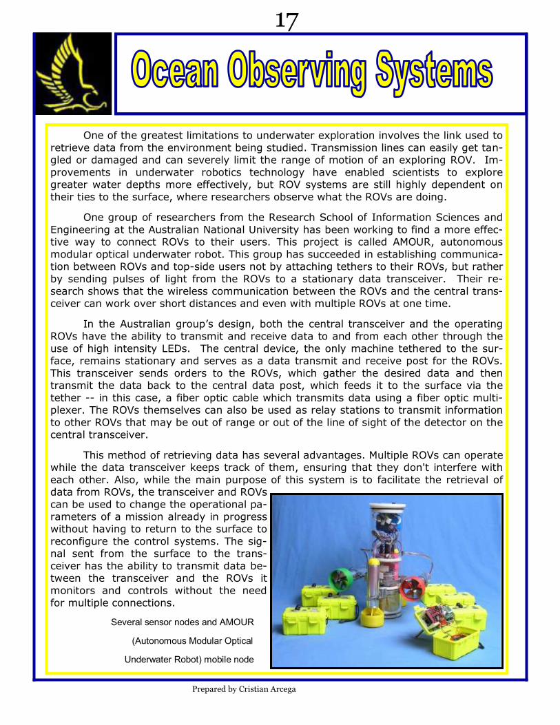
This method of retrieving data has several advantages. Multiple ROVs can operate
while the data transceiver keeps track of them, ensuring that they don't interfere with
each other. Also, while the main purpose of this system is to facilitate the retrieval of
data from ROVs, the transceiver and ROVs
can be used to change the operational pa-
rameters of a mission already in progress
without having to return to the surface to
reconfigure the control systems. The sig-
nal sent from the surface to the trans-
ceiver has the ability to transmit data be-
tween the transceiver and the ROVs it
monitors and controls without the need
for multiple connections.
Several sensor nodes and AMOUR
(Autonomous Modular Optical
Underwater Robot) mobile node
Prepared by Cristian Arcega
17
Supporting Ocean Observation Systems:
• http://groups.csail.mit.edu/drl/underwater_robotics/amour/amour.html
• Visible Spectrum Optical Communications and Distance Sensing for Underwater Applica-tions. www.araa.asn.au
• http://users.rsise.anu.edu.au/~trumpf/schill_zimmer_trumpf_ACRA2004.pdf
• http://www.spawar.navy.mil/depts/d70/d74/AdvancedConcepts.html
• http://groups.csail.mit.edu/drl/publications/papers/ICRA05b.pdf
• http://www.stanford.edu/class/cs344a/papers/p154-vasilescu.pdf
Sponsors and technical support:
• Walt Ahland, Lights Camera Action, 806 W. Impala Circle, Mesa, Arizona 85210-5996,
• Karen Suhm, PHD in Physics, former Microchip employee, currently running her own engi-neering firm, Inventivity
• International Fiber Systems Inc., 16 Commerce Rd., Newtown, CT 07460 USA
• Princetel Inc., Fiber Optics Products, 4 Prince Rd. Suite 209, Lawrenceville, NJ, 08648
• Donald Rodocker, President from Seabotix 1425 Russ Blvd, T112D, Sandiego, CA 92101,
don @seabotix.com
• Innovation FIRST inc., 6611 Interstate 30 west, Greenville, Texas, 75402 www.innovationfirst.com
• Scuba Sciences Inc Arizona Divers Supply Inc , 348 N 7 St , Phoenix, AZ 85006 - 1606
• Phoenix Tool & Gauge 2612 W Encanto Blvd, Phoenix, AZ 85009 - 1713
• Syntech Materials, Inc. P.O. Box 5242, Springfield, Virginia 22150
The following companies also donated products and services
Otter Box, Inc., Optical Cable Corp., Pairmate, Cable Data Products, Seacon, Southwest Fastener, Fastsigns, Supercircuits
Additional sponsors: Financial
Phelps Dodge Corp., Honeywell, Intel, Wells Fargo, Microchip corp. Arthur M. Blank Founda-tion, Ira P. Fulton Foundation, SEAD, Inventivity
Prepared by Annalisa Regalado
18